8254 Timer 8254 Timer

Welcome message from author
This document is posted to help you gain knowledge. Please leave a comment to let me know what you think about it! Share it to your friends and learn new things together.
Transcript

8254 Timer8254 Timer
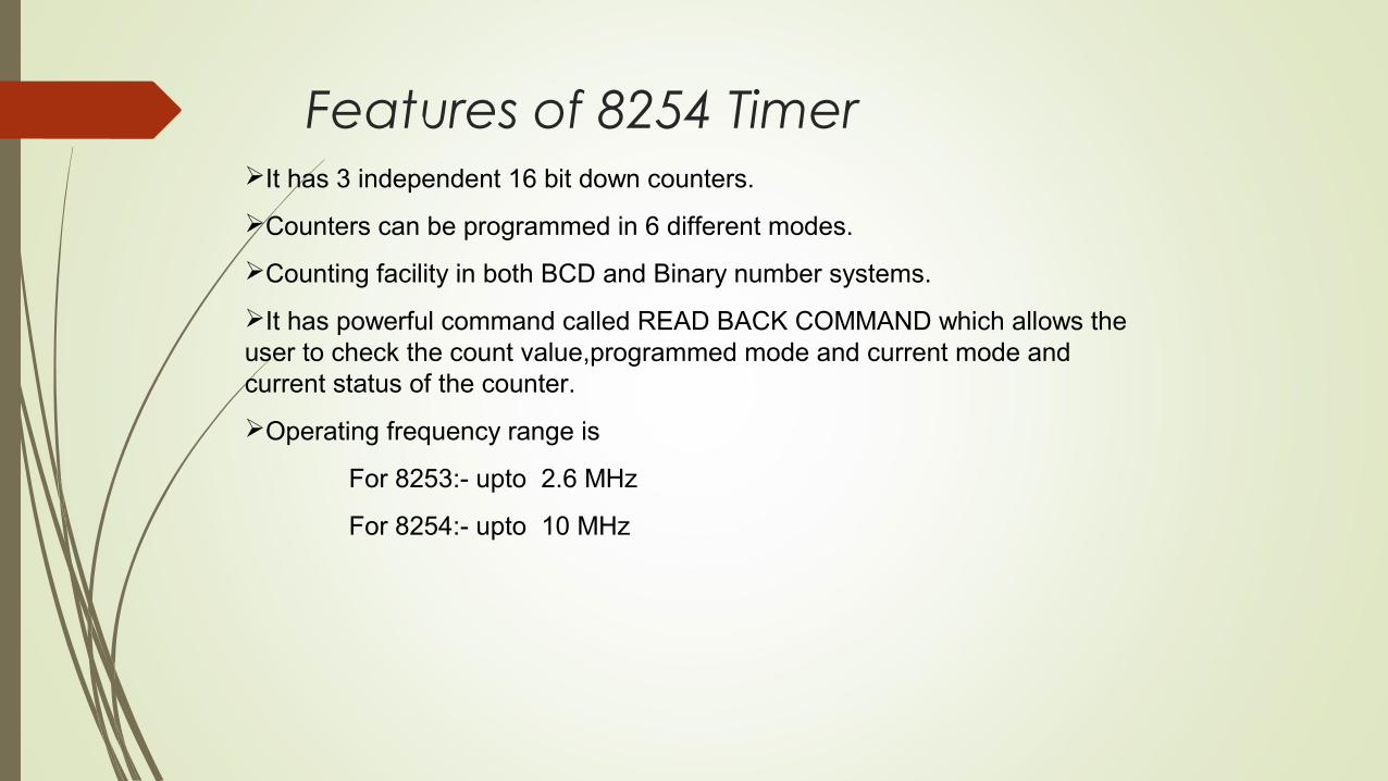
Features of 8254 TimerIt has 3 independent 16 bit down counters.
Counters can be programmed in 6 different modes.
Counting facility in both BCD and Binary number systems.
It has powerful command called READ BACK COMMAND which allows the user to check the count value,programmed mode and current mode and current status of the counter.
Operating frequency range is
For 8253:- upto 2.6 MHz
For 8254:- upto 10 MHz


8254 Functional Description
Figure shows the pin-out of the 8254,a higher-speed version of the 8253, and a diagram of one of the three counters.
Each timer contains: a CLK input which provides the basic operating frequency
to the timer a gate input pin which controls the timer in some modes an output (OUT) connection to obtain the output
of the timer
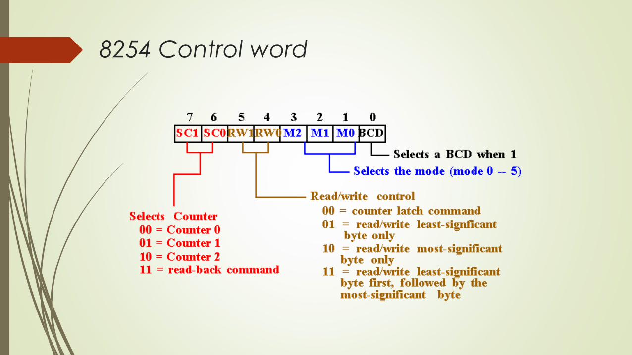
8254 Control word
8254 Programming
Each counter may be programmed with a count of 1 to FFFFH. Minimum count is 1 all modes except 2 and 3 with minimum count of 2.
Each counter has a program control word used to select the way the counter operates. If two bytes are programmed, then the first byte (LSB) stops the count, and the
second byte (MSB) starts the counter with the new count.

Mode 0: Interrupt on terminal count
- The output becomes a logic 0 when the control word is written -and remains there until N plus the number of programmed counts-When the Gate goes low the counter pauses. It resumes when Gates becomes high again
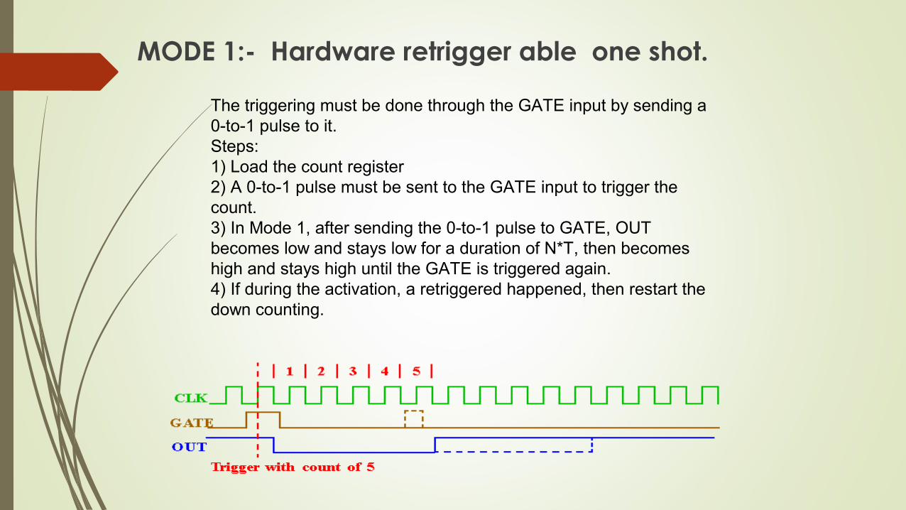
MODE 1:- Hardware retrigger able one shot.
The triggering must be done through the GATE input by sending a 0-to-1 pulse to it.Steps: 1) Load the count register2) A 0-to-1 pulse must be sent to the GATE input to trigger the count.3) In Mode 1, after sending the 0-to-1 pulse to GATE, OUT becomes low and stays low for a duration of N*T, then becomes high and stays high until the GATE is triggered again.4) If during the activation, a retriggered happened, then restart the down counting.
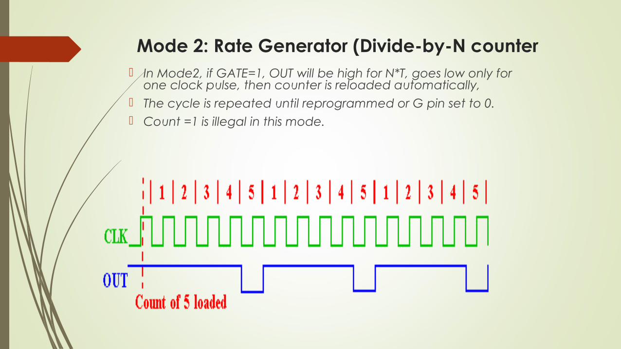
Mode 2: Rate Generator (Divide-by-N counter In Mode2, if GATE=1, OUT will be high for N*T, goes low only for
one clock pulse, then counter is reloaded automatically, The cycle is repeated until reprogrammed or G pin set to 0. Count =1 is illegal in this mode.
Mode 3: Square wave rate generator
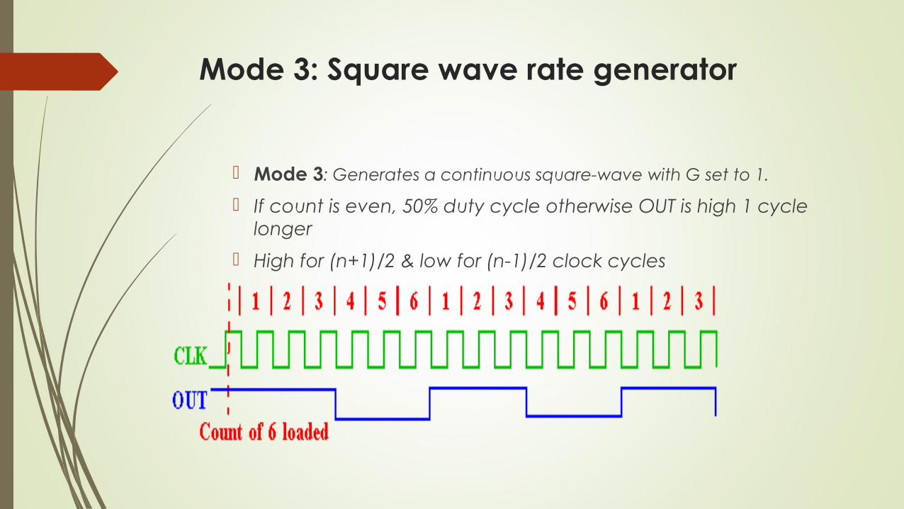
Mode 3: Generates a continuous square-wave with G set to 1.
If count is even, 50% duty cycle otherwise OUT is high 1 cycle longer
High for (n+1)/2 & low for (n-1)/2 clock cycles
Mode 4: Software triggered strobe
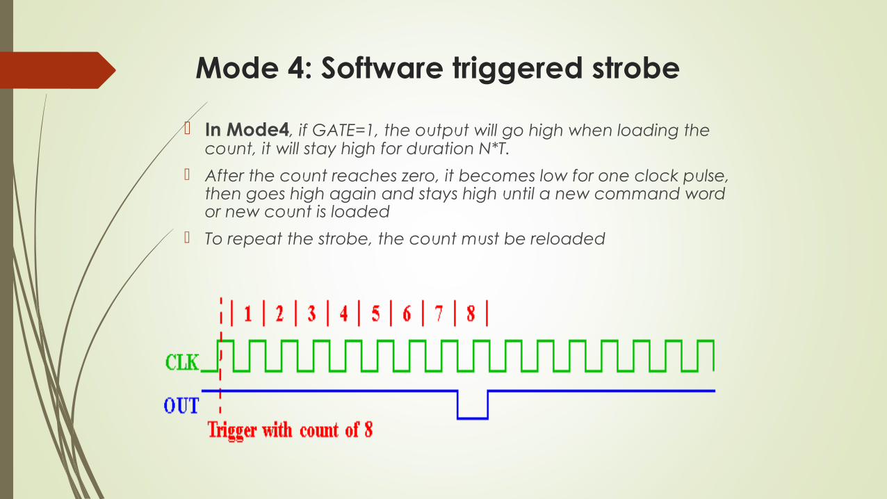
In Mode4, if GATE=1, the output will go high when loading the count, it will stay high for duration N*T.
After the count reaches zero, it becomes low for one clock pulse, then goes high again and stays high until a new command word or new count is loaded
To repeat the strobe, the count must be reloaded
Mode 5: Hardware triggered strobe
Similar to Mode4, except that the triggering must be done with the GATE input
The count starts only when a 0-to-1 pulse is sent to the GATE input
If GATE retriggered during the counting, it will restart the down counting
Read Operations There are three possible methods for reading the counters:1. a simple read operation2. the Counter Latch Command3. the Read-Back Command1. Simple read operation : The Counter which is selected with the A1, A0 inputs, the CLK input of the selected Counter must be inhibited by using either the GATE input or external logic. Otherwise, the count may be in the process of changing when it is read, giving an undefined result.
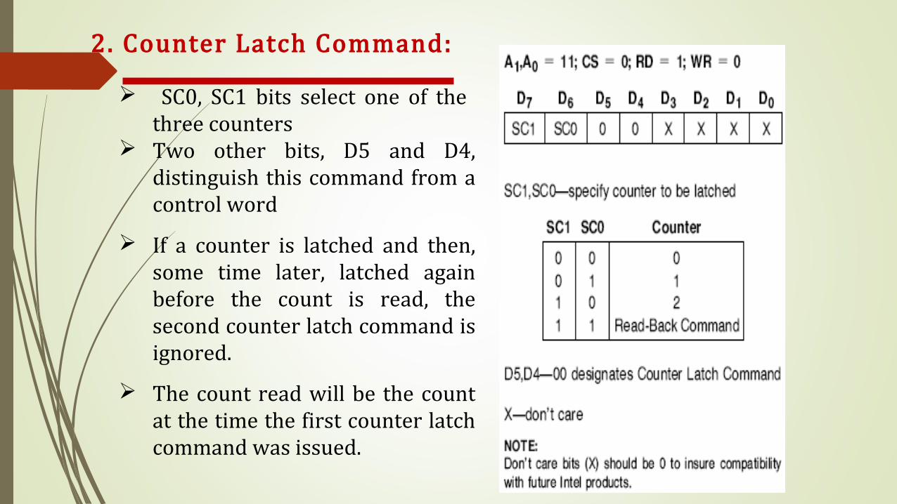
2. Counter Latch Command: SC0, SC1 bits select one of the three counters Two other bits, D5 and D4, distinguish this command from a control word If a counter is latched and then, some time later, latched again before the count is read, the second counter latch command is ignored. The count read will be the count at the time the first counter latch command was issued.
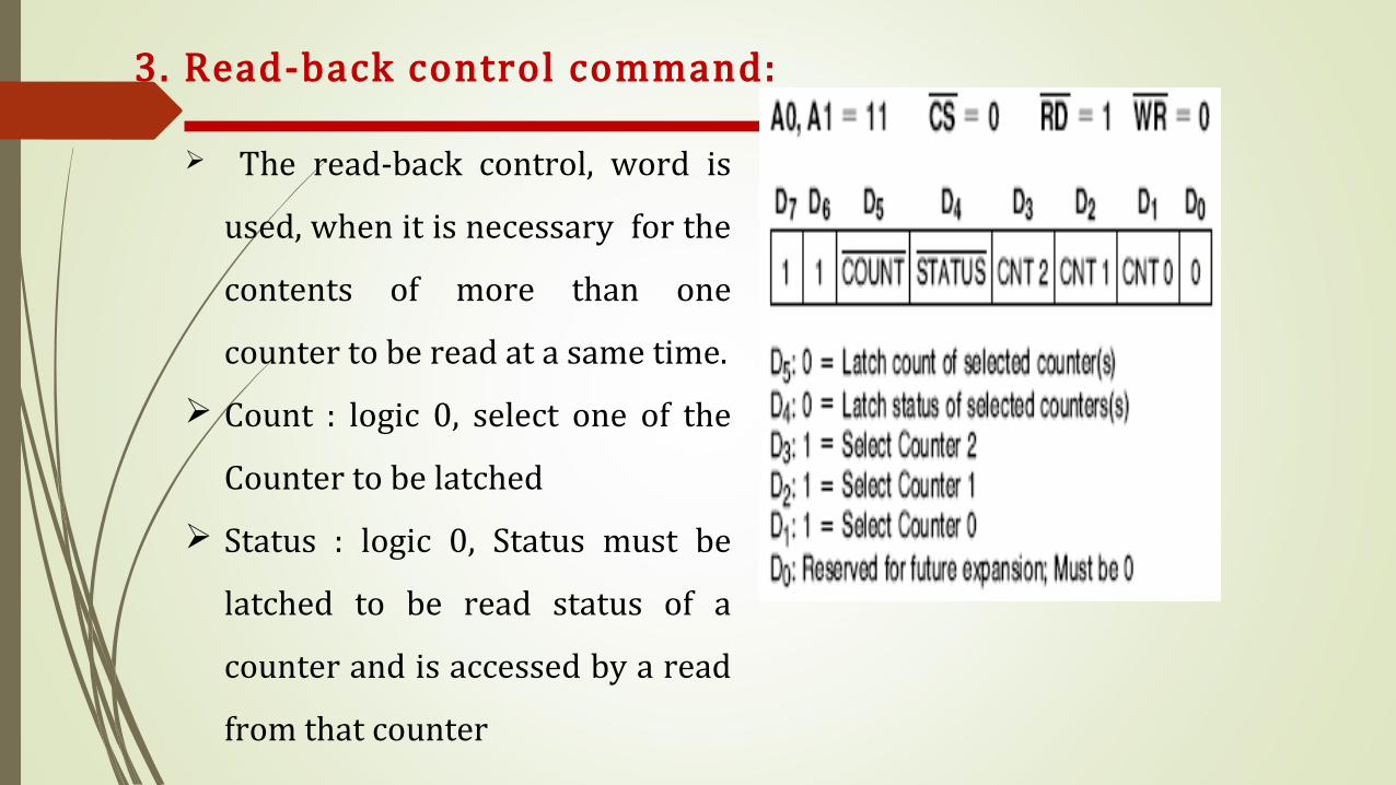
3. Read-back control command: The read-back control, word is used, when it is necessary for the contents of more than one counter to be read at a same time. Count : logic 0, select one of the Counter to be latched Status : logic 0, Status must be latched to be read status of a counter and is accessed by a read from that counter
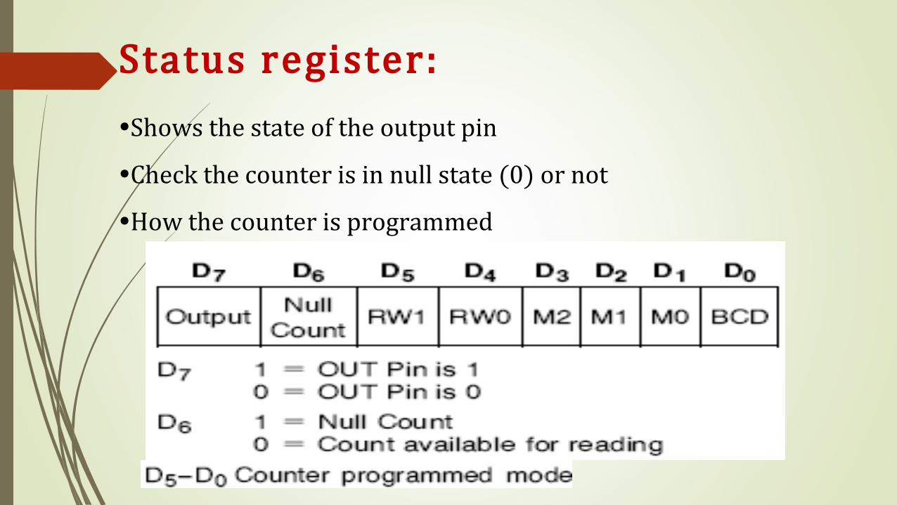
Status register:•Shows the state of the output pin•Check the counter is in null state (0) or not•How the counter is programmed
Related Documents