Georgia Coastal Stormwater Supplement April 2009 7.0 Green Infrastructure Practices 7.1 Overview Green infrastructure practices are natural resource protection and stormwater management practices and techniques (i.e.., better site planning and design techniques, low impact development practices) that can be used to help prevent increases in post-construction stormwater runoff rates, volumes and pollutant loads on development sites. Although the term green infrastructure can mean different things to different people (Box 4.1), in this Coastal Stormwater Supplement (CSS), the term green infrastructure practices has been succinctly defined as the combination of three complementary, but distinct, groups of natural resource protection and stormwater management practices and techniques: Better Site Planning Techniques : Techniques that are used to protect valuable aquatic and terrestrial resources from the direct impacts of the land development process. Better Site Design Techniques : Techniques that are used to minimize land disturbance and the creation of new impervious and disturbed pervious cover. Low Impact Development Practices : Small-scale stormwater management practices that are used to disconnect impervious and disturbed pervious surfaces from the storm drain system and reduce post-construction stormwater runoff rates, volumes and pollutant loads. Together, these green infrastructure practices can be used to not only help protect coastal Georgia’s valuable terrestrial and aquatic resources from the direct impacts of the land development process, but also help maintain pre-development site hydrology and reduce post- construction stormwater runoff rates, volumes and pollutant loads. They also provide a number of other environmental and economic benefits, including (US EPA, 2008): Reduced Sanitary and Combined Sewer Overflow Events : By reducing stormwater runoff rates and volumes, green infrastructure practices help reduce the magnitude and frequency of combined and sanitary sewer overflow events. Urban Heat Island Mitigation : The trees, shrubs and other vegetation associated with green infrastructure practices create shade, reflect solar radiation and emit water vapor, all of which create cooler temperatures in urban environments and help mitigate the impacts of urban heat islands. Reduced Energy Demand : The trees, shrubs and other vegetation associated with green infrastructure practices help lower ambient air temperatures in urban areas and, when incorporated on and around buildings, help insulate buildings from temperature swings, decreasing the amount of energy used for heating and cooling. Improved Air Quality : The trees, shrubs and other vegetation associated with green infrastructure practices improve air quality by removing many airborne pollutants from the atmosphere through the processes of leaf uptake and contact removal. Increased Carbon Sequestration : The trees, shrubs and other vegetation associated with green infrastructure practices are able to capture and remove carbon from the atmosphere through the processes of photosynthesis and respiration. Georgia Coastal Stormwater Supplement 7-1

Welcome message from author
This document is posted to help you gain knowledge. Please leave a comment to let me know what you think about it! Share it to your friends and learn new things together.
Transcript
Georgia Coastal Stormwater Supplement April 2009
7.0 Green Infrastructure Practices 7.1 Overview Green infrastructure practices are natural resource protection and stormwater management practices and techniques (i.e.., better site planning and design techniques, low impact development practices) that can be used to help prevent increases in post-construction stormwater runoff rates, volumes and pollutant loads on development sites. Although the term green infrastructure can mean different things to different people (Box 4.1), in this Coastal Stormwater Supplement (CSS), the term green infrastructure practices has been succinctly defined as the combination of three complementary, but distinct, groups of natural resource protection and stormwater management practices and techniques:
Better Site Planning Techniques: Techniques that are used to protect valuable aquatic and terrestrial resources from the direct impacts of the land development process.
Better Site Design Techniques: Techniques that are used to minimize land disturbance
and the creation of new impervious and disturbed pervious cover. Low Impact Development Practices: Small-scale stormwater management practices that
are used to disconnect impervious and disturbed pervious surfaces from the storm drain system and reduce post-construction stormwater runoff rates, volumes and pollutant loads.
Together, these green infrastructure practices can be used to not only help protect coastal Georgia’s valuable terrestrial and aquatic resources from the direct impacts of the land development process, but also help maintain pre-development site hydrology and reduce post-construction stormwater runoff rates, volumes and pollutant loads. They also provide a number of other environmental and economic benefits, including (US EPA, 2008):
Reduced Sanitary and Combined Sewer Overflow Events: By reducing stormwater runoff rates and volumes, green infrastructure practices help reduce the magnitude and frequency of combined and sanitary sewer overflow events.
Urban Heat Island Mitigation: The trees, shrubs and other vegetation associated with
green infrastructure practices create shade, reflect solar radiation and emit water vapor, all of which create cooler temperatures in urban environments and help mitigate the impacts of urban heat islands.
Reduced Energy Demand: The trees, shrubs and other vegetation associated with green
infrastructure practices help lower ambient air temperatures in urban areas and, when incorporated on and around buildings, help insulate buildings from temperature swings, decreasing the amount of energy used for heating and cooling.
Improved Air Quality: The trees, shrubs and other vegetation associated with green
infrastructure practices improve air quality by removing many airborne pollutants from the atmosphere through the processes of leaf uptake and contact removal.
Increased Carbon Sequestration: The trees, shrubs and other vegetation associated with
green infrastructure practices are able to capture and remove carbon from the atmosphere through the processes of photosynthesis and respiration.
Georgia Coastal Stormwater Supplement 7-1

Georgia Coastal Stormwater Supplement April 2009
Improved Aesthetics: The trees, shrubs and other vegetation associated with green infrastructure practices improve aesthetics, provide recreational opportunities and wildlife habitat and increase property values (MacMullan and Reich, 2007, US EPA, 2007, Winer-Skonovd et al., 2006).
Improved Human Health: An increasing number of studies suggest that the trees, shrubs
and other vegetation associated with green infrastructure practices can have a positive impact on human health. Recent research has linked the presence of trees, plants and other vegetation to reduced levels of crime and violence, a stronger sense of community, improved academic performance and even reductions in the symptoms associated with attention deficit and hyperactivity disorders (Faber-Taylor and Kuo, 2006, Kuo, 2003, Sullivan et al., 2003, Kuo and Sullivan, 2001, Taylor et al., 1998).
This Section provides additional information about using these green infrastructure practices to help satisfy the stormwater management and site planning and design criteria presented in this CSS. Together with stormwater management practices, which can be used to manage post-construction stormwater runoff rates, volumes and pollutant loads, green infrastructure practices can be used to help control and minimize the negative impacts of land development and nonpoint source pollution. They are an important part of the integrated, green infrastructure-based approach to natural resource protection, stormwater management and site design presented in this CSS. 7.2 Recommended Green Infrastructure Practices The green infrastructure practices recommended for use in coastal Georgia include: Better Site Planning Techniques
Protect Primary Conservation Areas Protect Secondary Conservation Areas
Better Site Design Techniques
Reduce Clearing and Grading Limits Reduce Roadway Lengths and Widths Use Fewer or Alternative Cul-de-Sacs Reduce Parking Lot Footprints Create Landscaping Areas in Parking Lots Reduce Driveway Lengths and Widths Reduce Sidewalk Lengths and Widths Reduce Building Footprints Reduce Setbacks and Frontages
Low Impact Development Practices The low impact development practices recommended for use in coastal Georgia have been divided into three groups: (1) alternatives to disturbed pervious surfaces; (2) alternatives to impervious surfaces; and (3) “receiving” low impact development practices. Each of these groups is briefly described below:
Georgia Coastal Stormwater Supplement 7-2
Georgia Coastal Stormwater Supplement April 2009
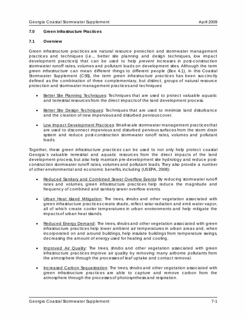
Alternatives to Disturbed Pervious Surfaces These low impact development practices can be used to help restore disturbed pervious surfaces to their pre-development conditions, which decreases post-construction stormwater runoff rates, volumes and pollutant loads. They can be used alone or in combination with one another to restore soils and native vegetative cover in areas that have been or will be disturbed by clearing, grading and other land disturbing activities (Figure 7.1). The alternatives to disturbed pervious surfaces recommended for use in coastal Georgia include:
Soil Restoration Site Reforestation/Revegetation
Alternatives to Impervious Surfaces
Figure 7.1: Reforestation of a Disturbed Pervious Area These low impact development practices can be
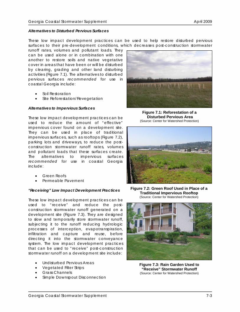
used to reduce the amount of “effective” impervious cover found on a development site. They can be used in place of traditional impervious surfaces, such as rooftops (Figure 7.2), parking lots and driveways, to reduce the post-construction stormwater runoff rates, volumes and pollutant loads that these surfaces create. The alternatives to impervious surfaces recommended for use in coastal Georgia include:
(Source: Center for Watershed Protection)
Green Roofs Permeable Pavement
Figure 7.2: Green Roof Used in Place of a
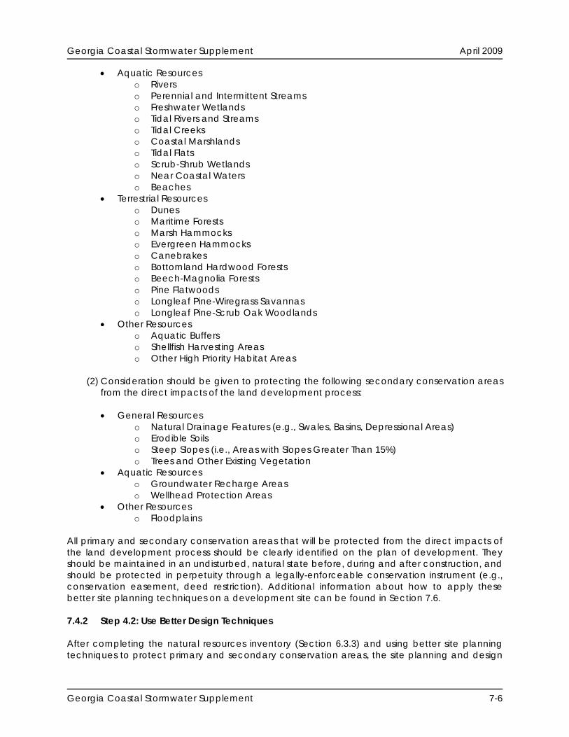
Traditional Impervious Rooftop “Receiving” Low Impact Development Practices (Source: Center for Watershed Protection) These low impact development practices can be used to “receive” and reduce the post-construction stormwater runoff generated on a development site (Figure 7.3). They are designed to slow and temporarily store stormwater runoff, subjecting it to the runoff reducing hydrologic processes of interception, evapotranspiration, infiltration and capture and reuse, before directing it into the stormwater conveyance system. The low impact development practices that can be used to “receive” post-construction stormwater runoff on a development site include:
Undisturbed Pervious Areas Figure 7.3: Rain Garden Used to “Receive” Stormwater Runoff Vegetated Filter Strips
Grass Channels (Source: Center for Watershed Protection)
Simple Downspout Disconnection
Georgia Coastal Stormwater Supplement 7-3

Georgia Coastal Stormwater Supplement April 2009
Georgia Coastal Stormwater Supplement 7-4
Rain Gardens Stormwater Planters Dry Wells Rainwater Harvesting Bioretention Areas Infiltration Practices Dry Swales
The remainder of this Section provides additional information about all of these green infrastructure practices, including information about their proper application and design and information about how they can be used to help satisfy the stormwater management and site planning and design criteria presented in this CSS. 7.3 Other Green Infrastructure Practices 7.3.1 New and Innovative Green Infrastructure Practices The use of new and innovative green infrastructure practices is encouraged in coastal Georgia, provided that their ability to satisfy the stormwater management and site planning and design criteria presented in this CSS has been sufficiently documented. At its discretion, a local development review authority may allow for the use of a green infrastructure practice that is not discussed in this CSS. However, local development review authorities are encouraged not to do so until they are provided with reliable information about practice performance and information about practice design and maintenance requirements. New and innovative green infrastructure practices will not be added to this CSS until reliable, independently derived performance monitoring data confirm their ability to satisfy the stormwater management and site planning and design criteria presented within. Appendix C outlines a stormwater management monitoring protocol that can be used to help document the performance of new and innovative green infrastructure practices in coastal Georgia. 7.4 Applying Green Infrastructure Practices During the Site Planning & Design Process A procedure that can be used to apply green infrastructure practices to a development site during the site planning and design process is illustrated in Figure 7.4 and briefly outlined below. 7.4.1 Step 4.1: Use Better Site Planning Techniques After completing the natural resources inventory (Section 6.3.3), site planning and design teams should be able to identify the primary and secondary conservation areas found on the development site. In accordance with site planning and design criteria #2 (SP&D Criteria #2) (Section 4.3.2), it is recommended that:
(1) The following primary conservation areas, which provide habitat for high priority plant and animal species (Appendix A) and are considered to be high priority habitat areas (WRD, 2005), be protected from the direct impacts of the land development process:

Georgia Coastal Stormwater Supplement April 2009
Georgia Coastal Stormwater Supplement 7-5
Figure 7.4: Using Green Infrastructure Practices During the Creation of a Stormwater Management Concept Plan (Source: Center for Watershed Protection)
Georgia Coastal Stormwater Supplement April 2009
Aquatic Resources o Rivers o Perennial and Intermittent Streams o Freshwater Wetlands o Tidal Rivers and Streams o Tidal Creeks o Coastal Marshlands o Tidal Flats o Scrub-Shrub Wetlands o Near Coastal Waters o Beaches
Terrestrial Resources o Dunes o Maritime Forests o Marsh Hammocks o Evergreen Hammocks o Canebrakes o Bottomland Hardwood Forests o Beech-Magnolia Forests o Pine Flatwoods o Longleaf Pine-Wiregrass Savannas o Longleaf Pine-Scrub Oak Woodlands
Other Resources o Aquatic Buffers o Shellfish Harvesting Areas o Other High Priority Habitat Areas
(2) Consideration should be given to protecting the following secondary conservation areas from the direct impacts of the land development process:
General Resources
o Natural Drainage Features (e.g., Swales, Basins, Depressional Areas) o Erodible Soils o Steep Slopes (i.e., Areas with Slopes Greater Than 15%) o Trees and Other Existing Vegetation
Aquatic Resources o Groundwater Recharge Areas o Wellhead Protection Areas
Other Resources o Floodplains
All primary and secondary conservation areas that will be protected from the direct impacts of the land development process should be clearly identified on the plan of development. They should be maintained in an undisturbed, natural state before, during and after construction, and should be protected in perpetuity through a legally-enforceable conservation instrument (e.g., conservation easement, deed restriction). Additional information about how to apply these better site planning techniques on a development site can be found in Section 7.6. 7.4.2 Step 4.2: Use Better Design Techniques After completing the natural resources inventory (Section 6.3.3) and using better site planning techniques to protect primary and secondary conservation areas, the site planning and design
Georgia Coastal Stormwater Supplement 7-6

Georgia Coastal Stormwater Supplement April 2009
team should be able to define the buildable area on the development site. In accordance with SP&D Criteria #2 (Section 4.3.2), it is recommended that consideration be given to using better site design techniques to minimize land disturbance and limit the creation of new impervious and disturbed pervious cover within this buildable area. Additional information about these better site design techniques, including information about how to use them on a development site, can be found in Section 7.7. 7.4.3 Step 4.3: Calculate Stormwater Management Criteria Since the use of better site planning and design techniques can significantly reduce post-construction stormwater runoff rates, volumes and pollutant loads, site planning and design teams need not calculate the stormwater runoff volumes associated with the post-construction stormwater management criteria (SWM Criteria) that apply to a development site until they have completed an initial layout of the proposed development project. This helps provide the site planning and design team with a “blank canvas” during the creation of the development plan, one which is intended to encourage creativity and the use of a variety of better site planning and design techniques during the layout of the proposed development project. Information about calculating the stormwater runoff volumes associated with the SWM Criteria that apply to a development site is provided in Section 5.0, while information about applying the stormwater management “credits” associated with each of the better site planning and design techniques is provided in Sections 7.6-7.7. Once an initial estimate of the stormwater runoff volumes associated with the SWM Criteria that apply to a development site has been completed, site planning and design teams may want to go back to the development plan and apply additional better site design and planning techniques to further reduce post-construction stormwater runoff rates, volumes and pollutant loads. During this iterative site design process, several alternative development plans can be created and compared with one another to come up with a plan that will best “fit” the character of the site and best meet the SWM Criteria presented in this CSS. 7.4.4 Step 4.4: Apply Low Impact Development Practices After an initial layout of the proposed development project has been completed using better site planning and design techniques, and an initial estimate of the stormwater runoff volumes associated with the SWM Criteria that apply to a development site has been completed, site planning and design teams should be able to begin distributing low impact development practices across the development site. Many of these practices can be placed in the disturbed and undisturbed pervious areas that were protected earlier in the process through the use of better site planning and design techniques. At this point in the site planning and design process, a site planning and design team should have a pretty good understanding of the post-construction stormwater runoff rates, volumes and pollutant loads that they will need to manage on the development site. In accordance with SP&D Criteria #2 (Section 4.3.2), it is recommended that low impact development practices be used, to the maximum extent practical, to reduce these post-construction stormwater runoff rates, volumes and pollutant loads on the development site. Additional information about these low impact development practices, including information about their proper application and design, can be found in Section 7.8. When applying low impact development practices to a development site, it is important that they be treated just like stormwater management practices. They should be placed in drainage
Georgia Coastal Stormwater Supplement 7-7
Georgia Coastal Stormwater Supplement April 2009
or maintenance easements and included in all stormwater management system inspection and maintenance plans (SP&D Criteria #6). 7.4.5 Step 4.5: Check to See If Stormwater Management Criteria Have Been Met By distributing runoff reducing low impact development practices across a development site, and applying the associated stormwater management “credits,” it is possible to significantly reduce post-construction stormwater runoff rates, volumes and pollutant loads. Therefore, at this point in the process of creating a plan of development, it is recommended that site planning and design teams check to see if the SWM Criteria that apply to the development site have been met. Depending on the number and type of low impact development practices that have been used, the post-construction stormwater runoff rates, volumes and pollutant loads generated on the development site may have been significantly reduced. If so, the need for larger and more costly stormwater management practices, such as wet ponds and stormwater wetlands, may have been significantly reduced or may have been eliminated altogether. If a site planning and design team finds that the SWM Criteria that apply to a development site have not been completely satisfied, they may want to go back to the development plan to apply additional low impact development practices to further reduce post-construction stormwater runoff rates, volumes and pollutant loads on the development site. In accordance with SWM Criteria #1, if low impact development practices, in combination with the previously applied better site planning and design techniques, cannot, on their own, be used to completely satisfy the stormwater runoff reduction criteria (SWM Criteria #1), or any of the other SWM Criteria, stormwater management practices will need to be used on the development site (Section 6.3.4.6). Additional information about using stormwater management practices on a development site, including information about their proper application and design, can be found in Section 8.0. 7.5 Green Infrastructure Practice Selection A screening process that can be used to help decide what green infrastructure practices should be used on a development site is outlined below. This process is intended to assist site planning and design teams in selecting the most appropriate green infrastructure practices for use on a development site. In general, the following information should be considered when deciding what green infrastructure practices to use on a development site:
Ability to Help Satisfy the Stormwater Management Criteria Overall Feasibility Site Applicability
In addition, site planning and design teams should consider how the following site characteristics and constraints, which are commonly encountered in coastal Georgia, will influence the use of green infrastructure practices on a development site:
Poorly drained soils, such as hydrologic soil group C and D soils Well drained soils, such as hydrologic soil group A and B soils Flat terrain Shallow water table Tidally-influenced drainage
Georgia Coastal Stormwater Supplement 7-8
Georgia Coastal Stormwater Supplement April 2009
Georgia Coastal Stormwater Supplement 7-9
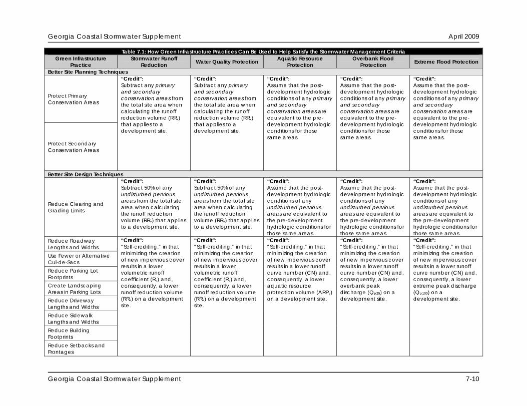
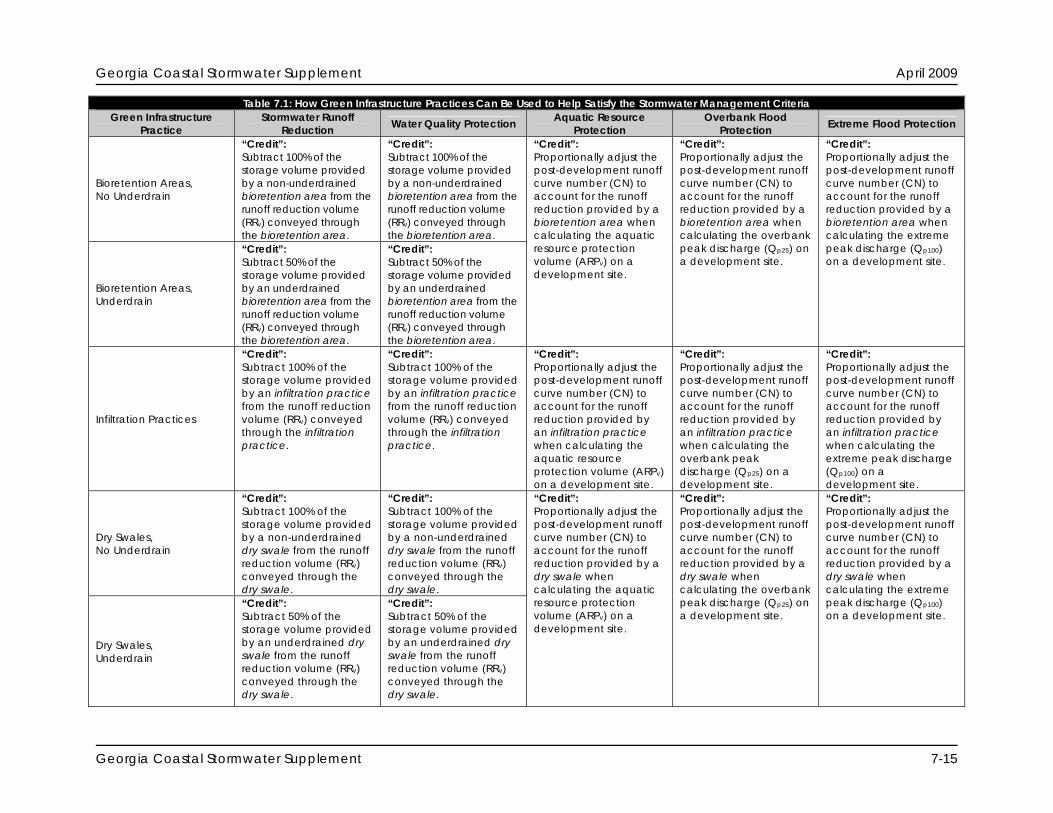
Additional information on a step-wise process that can be used to decide what green infrastructure practices to use on a development site is provided below. The process uses three screening matrices to evaluate the feasibility and applicability of the various green infrastructure practices recommended for use in coastal Georgia. 7.5.1 Step 1: Evaluate Ability to Help Satisfy the Stormwater Management Criteria Through the use of the first screening matrix (Table 7.1), site planning and design teams can evaluate how each of the green infrastructure practices can be used to help satisfy the post-construction stormwater management criteria that apply to a development site. Additional information about each of the screening categories included in the matrix is provided below.
Stormwater Runoff Reduction: This column indicates the stormwater management “credit” that can be applied toward the stormwater runoff reduction criteria (SWM Criteria #1) if the green infrastructure practice is used on the development site.
Water Quality Protection: This column indicates the stormwater management “credit”
that can be applied toward the water quality protection criteria (SWM Criteria #2) if the green infrastructure practice is used on the development site.
Aquatic Resource Protection: This column indicates the stormwater management
“credit” that can be applied toward the aquatic resource protection criteria (SWM Criteria #3) if the green infrastructure practice is used on the development site.
Overbank Flood Protection: This column indicates the stormwater management “credit”
that can be applied toward the overbank flood protection criteria (SWM Criteria #4) if the green infrastructure practice is used on the development site.
Extreme Flood Protection: This column indicates the stormwater management “credit”
that can be applied toward the extreme flood protection criteria (SWM Criteria #5) if the green infrastructure practice is used on the development site.
Georgia Coastal Stormwater Supplement April 2009
Table 7.1: How Green Infrastructure Practices Can Be Used to Help Satisfy the Stormwater Management Criteria Green Infrastructure
Practice Stormwater Runoff
Reduction Water Quality Protection Aquatic Resource Protection
Overbank Flood Protection Extreme Flood Protection
Better Site Planning Techniques
Protect Primary Conservation Areas
Protect Secondary Conservation Areas
“Credit”: Subtract any primary and secondary conservation areas from the total site area when calculating the runoff reduction volume (RRv) that applies to a development site.
“Credit”: Subtract any primary and secondary conservation areas from the total site area when calculating the runoff reduction volume (RRv) that applies to a development site.
“Credit”: Assume that the post-development hydrologic conditions of any primary and secondary conservation areas are equivalent to the pre-development hydrologic conditions for those same areas.
“Credit”: Assume that the post-development hydrologic conditions of any primary and secondary conservation areas are equivalent to the pre-development hydrologic conditions for those same areas.
“Credit”: Assume that the post-development hydrologic conditions of any primary and secondary conservation areas are equivalent to the pre-development hydrologic conditions for those same areas.
Better Site Design Techniques
Reduce Clearing and Grading Limits
“Credit”: Subtract 50% of any undisturbed pervious areas from the total site area when calculating the runoff reduction volume (RRv) that applies to a development site.
“Credit”: Subtract 50% of any undisturbed pervious areas from the total site area when calculating the runoff reduction volume (RRv) that applies to a development site.
“Credit”: Assume that the post-development hydrologic conditions of any undisturbed pervious areas are equivalent to the pre-development hydrologic conditions for those same areas.
“Credit”: Assume that the post-development hydrologic conditions of any undisturbed pervious areas are equivalent to the pre-development hydrologic conditions for those same areas.
“Credit”: Assume that the post-development hydrologic conditions of any undisturbed pervious areas are equivalent to the pre-development hydrologic conditions for those same areas.
Reduce Roadway Lengths and Widths Use Fewer or Alternative Cul-de-Sacs Reduce Parking Lot Footprints Create Landscaping Areas in Parking Lots Reduce Driveway Lengths and Widths Reduce Sidewalk Lengths and Widths Reduce Building Footprints Reduce Setbacks and Frontages
“Credit”: “Self-crediting,” in that minimizing the creation of new impervious cover results in a lower volumetric runoff coefficient (Rv) and, consequently, a lower runoff reduction volume (RRv) on a development site.
“Credit”: “Self-crediting,” in that minimizing the creation of new impervious cover results in a lower volumetric runoff coefficient (Rv) and, consequently, a lower runoff reduction volume (RRv) on a development site.
“Credit”: “Self-crediting,” in that minimizing the creation of new impervious cover results in a lower runoff curve number (CN) and, consequently, a lower aquatic resource protection volume (ARPv) on a development site.
“Credit”: “Self-crediting,” in that minimizing the creation of new impervious cover results in a lower runoff curve number (CN) and, consequently, a lower overbank peak discharge (Qp25) on a development site.
“Credit”: “Self-crediting,” in that minimizing the creation of new impervious cover results in a lower runoff curve number (CN) and, consequently, a lower extreme peak discharge (Qp100) on a development site.
Georgia Coastal Stormwater Supplement 7-10
Georgia Coastal Stormwater Supplement April 2009
Table 7.1: How Green Infrastructure Practices Can Be Used to Help Satisfy the Stormwater Management Criteria Green Infrastructure
Practice Stormwater Runoff
Reduction Water Quality Protection Aquatic Resource Overbank Flood Extreme Flood Protection Protection Protection Low Impact Development Practices Alternatives to Disturbed Pervious Surfaces
Soil Restoration
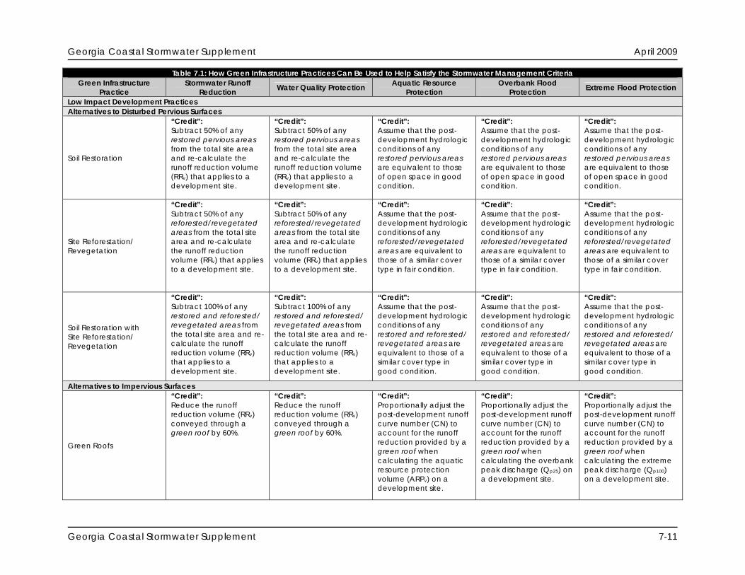
“Credit”: Subtract 50% of any restored pervious areas from the total site area and re-calculate the runoff reduction volume (RRv) that applies to a development site.
“Credit”: Subtract 50% of any restored pervious areas from the total site area and re-calculate the runoff reduction volume (RRv) that applies to a development site.
“Credit”: Assume that the post-development hydrologic conditions of any restored pervious areas are equivalent to those of open space in good condition.
“Credit”: Assume that the post-development hydrologic conditions of any restored pervious areas are equivalent to those of open space in good condition.
“Credit”: Assume that the post-development hydrologic conditions of any restored pervious areas are equivalent to those of open space in good condition.
Site Reforestation/ Revegetation
“Credit”: Subtract 50% of any reforested/revegetated areas from the total site area and re-calculate the runoff reduction volume (RRv) that applies to a development site.
“Credit”: Subtract 50% of any reforested/revegetated areas from the total site area and re-calculate the runoff reduction volume (RRv) that applies to a development site.
“Credit”: Assume that the post-development hydrologic conditions of any reforested/revegetated areas are equivalent to those of a similar cover type in fair condition.
“Credit”: Assume that the post-development hydrologic conditions of any reforested/revegetated areas are equivalent to those of a similar cover type in fair condition.
“Credit”: Assume that the post-development hydrologic conditions of any reforested/revegetated areas are equivalent to those of a similar cover type in fair condition.
Soil Restoration with Site Reforestation/ Revegetation
“Credit”: Subtract 100% of any restored and reforested/ revegetated areas from the total site area and re-calculate the runoff reduction volume (RRv) that applies to a development site.
“Credit”: Subtract 100% of any restored and reforested/ revegetated areas from the total site area and re-calculate the runoff reduction volume (RRv) that applies to a development site.
“Credit”: Assume that the post-development hydrologic conditions of any restored and reforested/ revegetated areas are equivalent to those of a similar cover type in good condition.
“Credit”: Assume that the post-development hydrologic conditions of any restored and reforested/ revegetated areas are equivalent to those of a similar cover type in good condition.
“Credit”: Assume that the post-development hydrologic conditions of any restored and reforested/ revegetated areas are equivalent to those of a similar cover type in good condition.
Alternatives to Impervious Surfaces
Green Roofs
“Credit”: Reduce the runoff reduction volume (RRv) conveyed through a green roof by 60%.
“Credit”: Reduce the runoff reduction volume (RRv) conveyed through a green roof by 60%.
“Credit”: Proportionally adjust the post-development runoff curve number (CN) to account for the runoff reduction provided by a green roof when calculating the aquatic resource protection volume (ARPv) on a development site.
“Credit”: Proportionally adjust the post-development runoff curve number (CN) to account for the runoff reduction provided by a green roof when calculating the overbank peak discharge (Qp25) on a development site.
“Credit”: Proportionally adjust the post-development runoff curve number (CN) to account for the runoff reduction provided by a green roof when calculating the extreme peak discharge (Qp100) on a development site.
Georgia Coastal Stormwater Supplement 7-11

Georgia Coastal Stormwater Supplement April 2009
Table 7.1: How Green Infrastructure Practices Can Be Used to Help Satisfy the Stormwater Management Criteria Green Infrastructure
Practice Stormwater Runoff
Reduction Water Quality Protection Aquatic Resource Overbank Flood Extreme Flood Protection Protection Protection
Permeable Pavement, No Underdrain
“Credit”: Subtract 100% of the storage volume provided by a non-underdrained permeable pavement system from the runoff reduction volume (RRv) conveyed through the system.
“Credit”: Subtract 100% of the storage volume provided by a non-underdrained permeable pavement system from the runoff reduction volume (RRv) conveyed through the system.
Permeable Pavement, Underdrain
“Credit”: Subtract 50% of the storage volume provided by an underdrained permeable pavement system from the runoff reduction volume (RRv) conveyed through the system.
“Credit”: Subtract 50% of the storage volume provided by an underdrained permeable pavement system from the runoff reduction volume (RRv) conveyed through the system.
“Credit”: Proportionally adjust the post-development runoff curve number (CN) to account for the runoff reduction provided by a permeable pavement system when calculating the aquatic resource protection volume (ARPv) on a development site.
“Credit”: Proportionally adjust the post-development runoff curve number (CN) to account for the runoff reduction provided by a permeable pavement system when calculating the overbank peak discharge (Qp25) on a development site.
“Credit”: Proportionally adjust the post-development runoff curve number (CN) to account for the runoff reduction provided by a permeable pavement system when calculating the extreme peak discharge (Qp100) on a development site.
“Receiving” Low Impact Development Practices
Undisturbed Pervious Areas, A/B Soils
“Credit”: Reduce the runoff reduction volume (RRv) conveyed through an undisturbed pervious area located on A/B soils by 90%.
“Credit”: Reduce the runoff reduction volume (RRv) conveyed through an undisturbed pervious area located on A/B soils by 90%.
Undisturbed Pervious Areas, C/D Soils
“Credit”: Reduce the runoff reduction volume (RRv) conveyed through an undisturbed pervious area located on C/D soils by 60%.
“Credit”: Reduce the runoff reduction volume (RRv) conveyed through an undisturbed pervious area located on C/D soils by 60%.
“Credit”: Proportionally adjust the post-development runoff curve number (CN) to account for the runoff reduction provided by an undisturbed pervious area when calculating the aquatic resource protection volume (ARPv) on a development site.
“Credit”: Proportionally adjust the post-development runoff curve number (CN) to account for the runoff reduction provided by an undisturbed pervious area when calculating the overbank peak discharge (Qp25) on a development site.
“Credit”: Proportionally adjust the post-development runoff curve number (CN) to account for the runoff reduction provided by an undisturbed pervious area when calculating the extreme peak discharge (Qp100) on a development site.
Georgia Coastal Stormwater Supplement 7-12
Georgia Coastal Stormwater Supplement April 2009
Table 7.1: How Green Infrastructure Practices Can Be Used to Help Satisfy the Stormwater Management Criteria Green Infrastructure
Practice Stormwater Runoff
Reduction Water Quality Protection Aquatic Resource Overbank Flood Extreme Flood Protection Protection Protection
Vegetated Filter Strips, A/B or Amended Soils
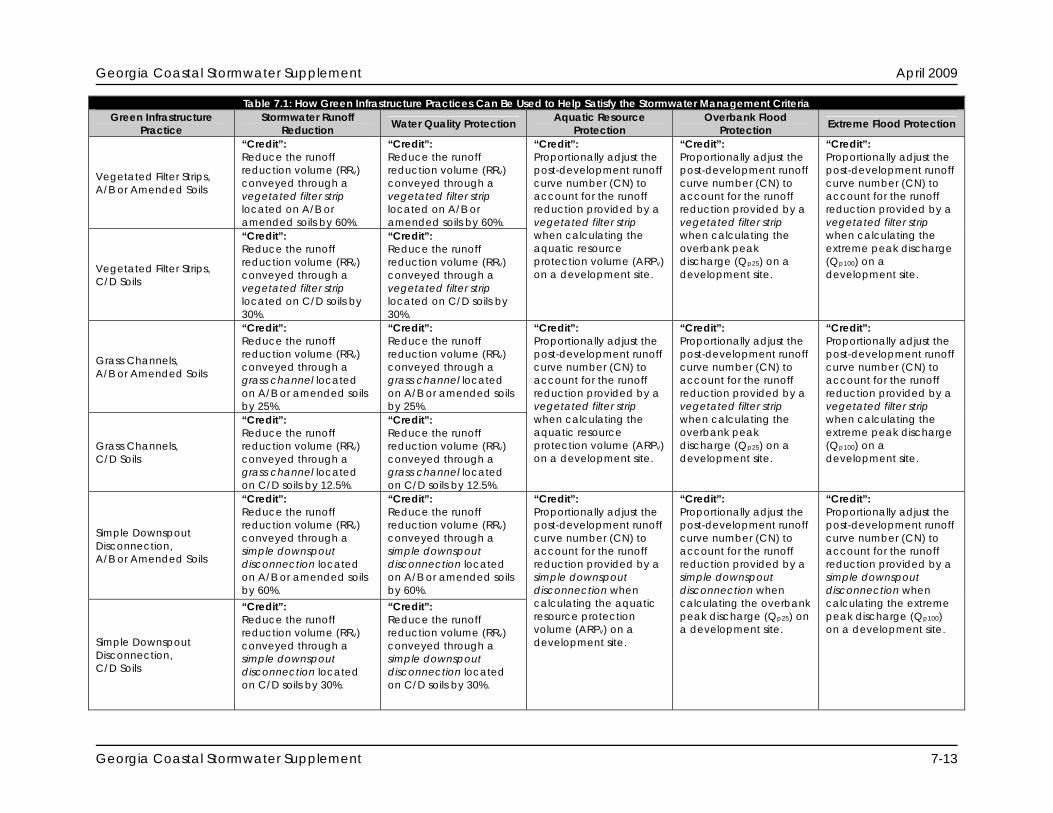
“Credit”: Reduce the runoff reduction volume (RRv) conveyed through a vegetated filter strip located on A/B or amended soils by 60%.
“Credit”: Reduce the runoff reduction volume (RRv) conveyed through a vegetated filter strip located on A/B or amended soils by 60%.
Vegetated Filter Strips, C/D Soils
“Credit”: Reduce the runoff reduction volume (RRv) conveyed through a vegetated filter strip located on C/D soils by 30%.
“Credit”: Reduce the runoff reduction volume (RRv) conveyed through a vegetated filter strip located on C/D soils by 30%.
“Credit”: Proportionally adjust the post-development runoff curve number (CN) to account for the runoff reduction provided by a vegetated filter strip when calculating the aquatic resource protection volume (ARPv) on a development site.
“Credit”: Proportionally adjust the post-development runoff curve number (CN) to account for the runoff reduction provided by a vegetated filter strip when calculating the overbank peak discharge (Qp25) on a development site.
“Credit”: Proportionally adjust the post-development runoff curve number (CN) to account for the runoff reduction provided by a vegetated filter strip when calculating the extreme peak discharge (Qp100) on a development site.
Grass Channels, A/B or Amended Soils
“Credit”: Reduce the runoff reduction volume (RRv) conveyed through a grass channel located on A/B or amended soils by 25%.
“Credit”: Reduce the runoff reduction volume (RRv) conveyed through a grass channel located on A/B or amended soils by 25%.
Grass Channels, C/D Soils
“Credit”: Reduce the runoff reduction volume (RRv) conveyed through a grass channel located on C/D soils by 12.5%.
“Credit”: Reduce the runoff reduction volume (RRv) conveyed through a grass channel located on C/D soils by 12.5%.
“Credit”: Proportionally adjust the post-development runoff curve number (CN) to account for the runoff reduction provided by a vegetated filter strip when calculating the aquatic resource protection volume (ARPv) on a development site.
“Credit”: Proportionally adjust the post-development runoff curve number (CN) to account for the runoff reduction provided by a vegetated filter strip when calculating the overbank peak discharge (Qp25) on a development site.
“Credit”: Proportionally adjust the post-development runoff curve number (CN) to account for the runoff reduction provided by a vegetated filter strip when calculating the extreme peak discharge (Qp100) on a development site.
Simple Downspout Disconnection, A/B or Amended Soils
“Credit”: Reduce the runoff reduction volume (RRv) conveyed through a simple downspout disconnection located on A/B or amended soils by 60%.
“Credit”: Reduce the runoff reduction volume (RRv) conveyed through a simple downspout disconnection located on A/B or amended soils by 60%.
Simple Downspout Disconnection, C/D Soils
“Credit”: Reduce the runoff reduction volume (RRv) conveyed through a simple downspout disconnection located on C/D soils by 30%.
“Credit”: Reduce the runoff reduction volume (RRv) conveyed through a simple downspout disconnection located on C/D soils by 30%.
“Credit”: Proportionally adjust the post-development runoff curve number (CN) to account for the runoff reduction provided by a simple downspout disconnection when calculating the aquatic resource protection volume (ARPv) on a development site.
“Credit”: Proportionally adjust the post-development runoff curve number (CN) to account for the runoff reduction provided by a simple downspout disconnection when calculating the overbank peak discharge (Qp25) on a development site.
“Credit”: Proportionally adjust the post-development runoff curve number (CN) to account for the runoff reduction provided by a simple downspout disconnection when calculating the extreme peak discharge (Qp100) on a development site.
Georgia Coastal Stormwater Supplement 7-13

Georgia Coastal Stormwater Supplement April 2009
Table 7.1: How Green Infrastructure Practices Can Be Used to Help Satisfy the Stormwater Management Criteria Green Infrastructure
Practice Stormwater Runoff
Reduction Water Quality Protection Aquatic Resource Overbank Flood Extreme Flood Protection Protection Protection
Rain Gardens
“Credit”: Subtract 100% of the storage volume provided by a rain garden from the runoff reduction volume (RRv) conveyed through the rain garden.
“Credit”: Subtract 100% of the storage volume provided by a rain garden from the runoff reduction volume (RRv) conveyed through the rain garden.
“Credit”: Proportionally adjust the post-development runoff curve number (CN) to account for the runoff reduction provided by a rain garden when calculating the aquatic resource protection volume (ARPv) on a development site.
“Credit”: Proportionally adjust the post-development runoff curve number (CN) to account for the runoff reduction provided by a rain garden when calculating the overbank peak discharge (Qp25) on a development site.
“Credit”: Proportionally adjust the post-development runoff curve number (CN) to account for the runoff reduction provided by a rain garden when calculating the extreme peak discharge (Qp100) on a development site.
Stormwater Planters
“Credit”: Subtract 50% of the storage volume provided by a stormwater planter from the runoff reduction volume (RRv) conveyed through the stormwater planter.
“Credit”: Subtract 50% of the storage volume provided by a stormwater planter from the runoff reduction volume (RRv) conveyed through the stormwater planter.
“Credit”: Proportionally adjust the post-development runoff curve number (CN) to account for the runoff reduction provided by a stormwater planter when calculating the aquatic resource protection volume (ARPv) on a development site.
“Credit”: Proportionally adjust the post-development runoff curve number (CN) to account for the runoff reduction provided by a stormwater planter when calculating the overbank peak discharge (Qp25) on a development site.
“Credit”: Proportionally adjust the post-development runoff curve number (CN) to account for the runoff reduction provided by a stormwater planter when calculating the extreme peak discharge (Qp100) on a development site.
Dry Wells
“Credit”: Subtract 100% of the storage volume provided by a dry well from the runoff reduction volume (RRv) conveyed through the dry well.
“Credit”: Subtract 100% of the storage volume provided by a dry well from the runoff reduction volume (RRv) conveyed through the dry well.
“Credit”: Proportionally adjust the post-development runoff curve number (CN) to account for the runoff reduction provided by a dry well when calculating the aquatic resource protection volume (ARPv) on a development site.
“Credit”: Proportionally adjust the post-development runoff curve number (CN) to account for the runoff reduction provided by a dry well when calculating the overbank peak discharge (Qp25) on a development site.
“Credit”: Proportionally adjust the post-development runoff curve number (CN) to account for the runoff reduction provided by a dry well when calculating the extreme peak discharge (Qp100) on a development site.
Rainwater Harvesting
“Credit”: Subtract 75% of the storage volume provided by a rainwater harvesting system from the runoff reduction volume (RRv) captured by the system.
“Credit”: Subtract 75% of the storage volume provided by a rainwater harvesting system from the runoff reduction volume (RRv) captured by the system.
“Credit”: Proportionally adjust the post-development runoff curve number (CN) to account for the runoff reduction provided by a rainwater harvesting system when calculating the aquatic resource protection volume (ARPv) on a development site.
“Credit”: Proportionally adjust the post-development runoff curve number (CN) to account for the runoff reduction provided by a rainwater harvesting system when calculating the overbank peak discharge (Qp25) on a development site.
“Credit”: Proportionally adjust the post-development runoff curve number (CN) to account for the runoff reduction provided by a rainwater harvesting system when calculating the extreme peak discharge (Qp100) on a development site.
Georgia Coastal Stormwater Supplement 7-14
Georgia Coastal Stormwater Supplement April 2009
Georgia Coastal Stormwater Supplement 7-15
Table 7.1: How Green Infrastructure Practices Can Be Used to Help Satisfy the Stormwater Management Criteria Green Infrastructure
Practice Stormwater Runoff
Reduction Water Quality Protection Aquatic Resource Protection
Overbank Flood Protection Extreme Flood Protection
Bioretention Areas, No Underdrain
“Credit”: Subtract 100% of the storage volume provided by a non-underdrained bioretention area from the runoff reduction volume (RRv) conveyed through the bioretention area.
“Credit”: Subtract 100% of the storage volume provided by a non-underdrained bioretention area from the runoff reduction volume (RRv) conveyed through the bioretention area.
Bioretention Areas, Underdrain
“Credit”: Subtract 50% of the storage volume provided by an underdrained bioretention area from the runoff reduction volume (RRv) conveyed through the bioretention area.
“Credit”: Subtract 50% of the storage volume provided by an underdrained bioretention area from the runoff reduction volume (RRv) conveyed through the bioretention area.
“Credit”: Proportionally adjust the post-development runoff curve number (CN) to account for the runoff reduction provided by a bioretention area when calculating the aquatic resource protection volume (ARPv) on a development site.
“Credit”: Proportionally adjust the post-development runoff curve number (CN) to account for the runoff reduction provided by a bioretention area when calculating the overbank peak discharge (Qp25) on a development site.
“Credit”: Proportionally adjust the post-development runoff curve number (CN) to account for the runoff reduction provided by a bioretention area when calculating the extreme peak discharge (Qp100) on a development site.
Infiltration Practices
“Credit”: Subtract 100% of the storage volume provided by an infiltration practice from the runoff reduction volume (RRv) conveyed through the infiltration practice.
“Credit”: Subtract 100% of the storage volume provided by an infiltration practice from the runoff reduction volume (RRv) conveyed through the infiltration practice.
“Credit”: Proportionally adjust the post-development runoff curve number (CN) to account for the runoff reduction provided by an infiltration practice when calculating the aquatic resource protection volume (ARPv) on a development site.
“Credit”: Proportionally adjust the post-development runoff curve number (CN) to account for the runoff reduction provided by an infiltration practice when calculating the overbank peak discharge (Qp25) on a development site.
“Credit”: Proportionally adjust the post-development runoff curve number (CN) to account for the runoff reduction provided by an infiltration practice when calculating the extreme peak discharge (Qp100) on a development site.
Dry Swales, No Underdrain
“Credit”: Subtract 100% of the storage volume provided by a non-underdrained dry swale from the runoff reduction volume (RRv) conveyed through the dry swale.
“Credit”: Subtract 100% of the storage volume provided by a non-underdrained dry swale from the runoff reduction volume (RRv) conveyed through the dry swale.
Dry Swales, Underdrain
“Credit”: Subtract 50% of the storage volume provided by an underdrained dry swale from the runoff reduction volume (RRv) conveyed through the dry swale.
“Credit”: Subtract 50% of the storage volume provided by an underdrained dry swale from the runoff reduction volume (RRv) conveyed through the dry swale.
“Credit”: Proportionally adjust the post-development runoff curve number (CN) to account for the runoff reduction provided by a dry swale when calculating the aquatic resource protection volume (ARPv) on a development site.
“Credit”: Proportionally adjust the post-development runoff curve number (CN) to account for the runoff reduction provided by a dry swale when calculating the overbank peak discharge (Qp25) on a development site.
“Credit”: Proportionally adjust the post-development runoff curve number (CN) to account for the runoff reduction provided by a dry swale when calculating the extreme peak discharge (Qp100) on a development site.
Georgia Coastal Stormwater Supplement April 2009
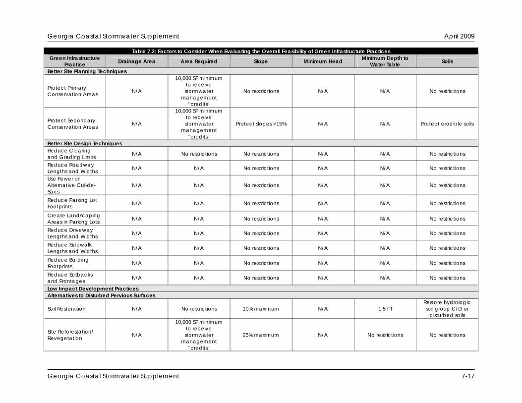
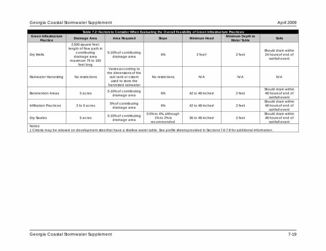
7.5.2 Step 2: Evaluate Overall Feasibility Through the use of the second screening matrix (Table 7.2), site planning and design teams can evaluate the overall feasibility of applying each of the green infrastructure practices on a development site. Additional information about each of the screening categories included in the matrix is provided below.
Drainage Area: This column describes how large of a contributing drainage area each green infrastructure practice can realistically handle. It indicates the maximum size of the contributing drainage area that each green infrastructure practice should be designed to “receive” stormwater runoff from.
Area Required: This column indicates how much space the green infrastructure practice
typically consumes on a development site.
Slope: This column describes the influence that site slope can have on the performance of the green infrastructure practice. It indicates the maximum or minimum slope on which the green infrastructure practice can be installed.
Minimum Head: This column provides an estimate of the minimum amount of elevation
difference needed within the green infrastructure practice, from the inflow to the outflow, to allow for gravity operation.
Minimum Depth to Water Table: This column indicates the minimum distance that should
be provided between the bottom of the green infrastructure practice and the top of the water table.
Soils: This column describes the influence that the underlying soils (i.e., hydrologic soil
groups) can have on the performance of the green infrastructure practice.
Georgia Coastal Stormwater Supplement 7-16
Georgia Coastal Stormwater Supplement April 2009
Table 7.2: Factors to Consider When Evaluating the Overall Feasibility of Green Infrastructure Practices Green Infrastructure
Practice Drainage Area Area Required Slope Minimum Head Minimum Depth to Water Table Soils
Better Site Planning Techniques
Protect Primary Conservation Areas N/A
10,000 SF minimum to receive stormwater
management “credits”
No restrictions N/A N/A No restrictions
Protect Secondary Conservation Areas N/A
10,000 SF minimum to receive stormwater
management “credits”
Protect slopes >15% N/A N/A Protect erodible soils
Better Site Design Techniques Reduce Clearing and Grading Limits N/A No restrictions No restrictions N/A N/A No restrictions
Reduce Roadway Lengths and Widths N/A N/A No restrictions N/A N/A No restrictions
Use Fewer or Alternative Cul-de-Sacs
N/A N/A No restrictions N/A N/A No restrictions
Reduce Parking Lot Footprints N/A N/A No restrictions N/A N/A No restrictions
Create Landscaping Areas in Parking Lots N/A N/A No restrictions N/A N/A No restrictions
Reduce Driveway Lengths and Widths N/A N/A No restrictions N/A N/A No restrictions
Reduce Sidewalk Lengths and Widths N/A N/A No restrictions N/A N/A No restrictions
Reduce Building Footprints N/A N/A No restrictions N/A N/A No restrictions
Reduce Setbacks and Frontages N/A N/A No restrictions N/A N/A No restrictions
Low Impact Development Practices Alternatives to Disturbed Pervious Surfaces
Soil Restoration N/A No restrictions 10% maximum N/A 1.5 FT Restore hydrologic soil group C/D or
disturbed soils
Site Reforestation/ Revegetation N/A
10,000 SF minimum to receive stormwater
management “credits”
25% maximum N/A No restrictions No restrictions
Georgia Coastal Stormwater Supplement 7-17

Georgia Coastal Stormwater Supplement April 2009
Table 7.2: Factors to Consider When Evaluating the Overall Feasibility of Green Infrastructure Practices Green Infrastructure
Practice Drainage Area Area Required Slope Minimum Depth to Minimum Head Soils Water Table Alternatives to Impervious Surfaces
Green Roofs N/A No restrictions 25% maximum,
although 10% or less is recommended
6 to 12 inches N/A Use appropriate
engineered growing media
Permeable Pavement N/A No restrictions 6% 2 to 4 feet 2 feet
Should drain within 48 hours of end of
rainfall event “Receiving” Low Impact Development Practices
Undisturbed Pervious Areas
Length of flow path in contributing drainage area
maximum 75 to 150 feet long
Length of flow path in undisturbed pervious area
minimum 50 feet long
Maximum 3% in contributing
drainage area; 0.5% to 6% in
undisturbed pervious area
N/A No restrictions No restrictions
Vegetated Filter Strips
Length of flow path in contributing drainage area
maximum 75 to 150 feet long
Length of flow path in vegetated filter
strip minimum 15 to 25 feet long
Maximum 3% in contributing
drainage area; 0.5% to 6% in
vegetated filter strip
N/A No restrictions No restrictions
Grass Channels 5 acres
Bottom of grass channel 2 to 8 feet wide; side slopes of
3:1 or flatter
0.5% to 3%, although 1% to 2% is
recommended N/A 2 feet No restrictions
Simple Downspout Disconnection
2,500 square feet; length of flow path in
contributing drainage area
maximum 75 feet long
Length of flow path at least 15 feet long
and equal to or greater than that of
contributing drainage area
0.5% to 6%, although 1% to 5% is
recommended N/A No restrictions No restrictions
Rain Gardens
2,500 square feet; length of flow path in
contributing drainage area
maximum 75 to 150 feet long
10-20% of contributing
drainage area 6% 30 to 36 inches1 2 feet
Should drain within 24 hours of end of
rainfall event
Stormwater Planters
2,500 square feet; length of flow path in
contributing drainage area
maximum 75 to 150 feet long
5% of contributing drainage area 6% 30 to 36 inches1 2 feet1
Should drain within 24 hours of end of
rainfall event
Georgia Coastal Stormwater Supplement 7-18
Georgia Coastal Stormwater Supplement April 2009
Georgia Coastal Stormwater Supplement 7-19
Table 7.2: Factors to Consider When Evaluating the Overall Feasibility of Green Infrastructure Practices Green Infrastructure
Practice Drainage Area Area Required Slope Minimum Head Minimum Depth to Water Table Soils
Dry Wells
2,500 square feet; length of flow path in
contributing drainage area
maximum 75 to 150 feet long
5-10% of contributing drainage area 6% 2 feet1 2 feet
Should drain within 24 hours of end of
rainfall event
Rainwater Harvesting No restrictions
Varies according to the dimensions of the
rain tank or cistern used to store the
harvested rainwater
No restrictions N/A N/A N/A
Bioretention Areas 5 acres 5-10% of contributing drainage area 6% 42 to 48 inches1 2 feet
Should drain within 48 hours of end of
rainfall event
Infiltration Practices 2 to 5 acres 5% of contributing drainage area 6% 42 to 48 inches1 2 feet
Should drain within 48 hours of end of
rainfall event
Dry Swales 5 acres 5-10% of contributing drainage area
0.5% to 4%, although 1% to 2% is
recommended 36 to 48 inches1 2 feet
Should drain within 48 hours of end of
rainfall event Notes: 1 Criteria may be relaxed on development sites that have a shallow water table. See profile sheets provided in Sections 7.6-7.8 for additional information.
Georgia Coastal Stormwater Supplement April 2009
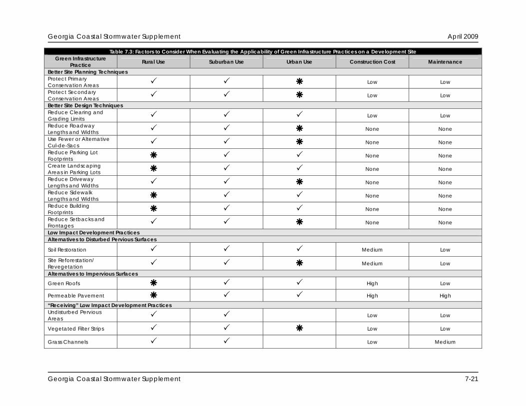
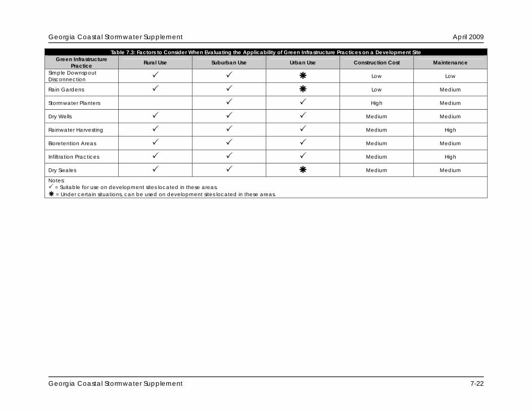
7.5.3 Step 3: Evaluate Site Applicability Through the use of the third screening matrix (Table 7.3), site planning and design teams can evaluate the applicability of each of the green infrastructure practices on a particular development site. Additional information about each of the screening categories included in the matrix is provided below.
Rural Use: This column indicates whether or not the green infrastructure practice is suitable for use in rural areas and on low-density development sites.
Suburban Use: This column indicates whether or not the green infrastructure practice is
suitable for use in suburban areas and on medium-density development sites.
Urban Use: This column identifies the green infrastructure practices that are suitable for use in urban and ultra-urban areas where space is at a premium.
Construction Cost: This column assesses the relative construction cost of each of the
green infrastructure practices.
Maintenance: This column assesses the relative maintenance burden associated with each green infrastructure practice. It is important to note that nearly all green infrastructure practices require some kind of routine inspection and maintenance.
Georgia Coastal Stormwater Supplement 7-20
Georgia Coastal Stormwater Supplement April 2009
Table 7.3: Factors to Consider When Evaluating the Applicability of Green Infrastructure Practices on a Development Site Green Infrastructure
Practice Rural Use Suburban Use Urban Use Construction Cost Maintenance
Better Site Planning Techniques Protect Primary Conservation Areas Low Low
Protect Secondary Conservation Areas Low Low
Better Site Design Techniques Reduce Clearing and Grading Limits Low Low
Reduce Roadway Lengths and Widths None None Use Fewer or Alternative Cul-de-Sacs None None Reduce Parking Lot Footprints None None Create Landscaping Areas in Parking Lots None None Reduce Driveway Lengths and Widths None None Reduce Sidewalk Lengths and Widths None None Reduce Building Footprints None None Reduce Setbacks and Frontages None None Low Impact Development Practices Alternatives to Disturbed Pervious Surfaces
Soil Restoration Medium Low
Site Reforestation/ Revegetation Medium Low
Alternatives to Impervious Surfaces
Green Roofs High Low
Permeable Pavement High High
“Receiving” Low Impact Development Practices Undisturbed Pervious Areas Low Low
Vegetated Filter Strips Low Low
Grass Channels Low Medium
Georgia Coastal Stormwater Supplement 7-21
Georgia Coastal Stormwater Supplement April 2009
Georgia Coastal Stormwater Supplement 7-22
Table 7.3: Factors to Consider When Evaluating the Applicability of Green Infrastructure Practices on a Development Site Green Infrastructure
Practice Rural Use Suburban Use Urban Use Construction Cost Maintenance
Simple Downspout Disconnection Low Low
Rain Gardens Low Medium
Stormwater Planters High Medium
Dry Wells Medium Medium
Rainwater Harvesting Medium High
Bioretention Areas Medium Medium
Infiltration Practices Medium High
Dry Swales Medium Medium
Notes: = Suitable for use on development sites located in these areas. = Under certain situations, can be used on development sites located in these areas.

Georgia Coastal Stormwater Supplement April 2009
7.6 Better Site Planning Technique Profile Sheets This Section contains profile sheets that provide information about the better site planning techniques that are recommended for use in coastal Georgia. The profile sheets describe each of the better site planning techniques and provide information about how they can be used to help satisfy the SWM Criteria presented in this CSS. The better site planning techniques profiled in this Section include: Better Site Planning Techniques
7.6.1 Preserve Primary Conservation Areas 7.6.2 Preserve Secondary Conservation Areas
Georgia Coastal Stormwater Supplement 7-23

Georgia Coastal Stormwater Supplement April 2009
THIS PAGE INTENTIONALLY LEFT BLANK
Georgia Coastal Stormwater Supplement 7-24

Georgia Coastal Stormwater Supplement April 2009
7.6.1 Protect Primary Conservation Areas Description Primary conservation areas, which include, but are not limited to, perennial and intermittent streams, freshwater wetlands, tidal creeks, coastal marshlands, maritime forests, marsh hammocks, aquatic buffers and shellfish harvesting areas, should be protected, in perpetuity, from the direct impacts of the land development process.
KEY CONSIDERATIONS
Protects important priority habitat areas from the
direct impacts of the land development process Helps maintain pre-development site hydrology
by reducing post-construction stormwater runoff rates, volumes and pollutant loads
Preserves a site’s natural character and aesthetic features, which may increase the resale value of the development project
Conservation areas can be used to “receive” stormwater runoff generated elsewhere on the development site (Section 7.8.5)
USING THIS TECHINQUE
Complete natural resources
inventory prior to initiating site planning and design process
Ensure that primary conservation
areas are maintained in an undisturbed, natural state before, during and after construction
Discussion Protecting primary conservation areas such as perennial and intermittent streams, freshwater wetlands, tidal creeks, coastal marshlands (Figure 7.5), maritime forests, marsh hammocks, aquatic buffers and shellfish harvesting areas, helps preserve important habitat for coastal Georgia’s high priority plant and animal species (Appendix A) and helps maintain pre-development site hydrology by reducing post-construction stormwater runoff rates, volumes and pollutant loads. It also helps prevent soil erosion and provides areas that can be used to “receive” stormwater runoff generated elsewhere on the development site (Section 7.8.5). The primary and secondary conservation areas found on a development site should be identified during the natural resources inventory (Section 6.3.3) and should be mapped at the very beginning of the site planning and design process (Figure 7.6). The identification and subsequent preservation and/or restoration of these natural resources helps reduce the negative impacts of the land development process “by design.” In accordance with SP&D Criteria #2 (Section 4.3.2), it is recommended that the following primary conservation areas, which provide habitat for high priority plant and animal species (Appendix A) and are considered to be high priority habitat areas (WRD, 2005), be protected
Figure 7.5: Coastal Marshlands are Considered to be a Primary Conservation Area
(Source: Center for Watershed Protection)
Georgia Coastal Stormwater Supplement 7-25

Georgia Coastal Stormwater Supplement April 2009
Figure 7.6: Primary and Secondary Conservation Areas Identified at the Beginning of the Site Planning and Design Process
(Source: Merrill et al., 2006)
from the direct impacts of the land development process:
Aquatic Resources o Rivers o Perennial and Intermittent Streams o Freshwater Wetlands o Tidal Rivers and Streams o Tidal Creeks o Coastal Marshlands o Tidal Flats o Scrub-Shrub Wetlands o Near Coastal Waters o Beaches
Terrestrial Resources o Dunes o Maritime Forests o Marsh Hammocks o Evergreen Hammocks o Canebrakes o Bottomland Hardwood Forests o Beech-Magnolia Forests
Georgia Coastal Stormwater Supplement 7-26
Georgia Coastal Stormwater Supplement April 2009
o Pine Flatwoods o Longleaf Pine-Wiregrass Savannas o Longleaf Pine-Scrub Oak Woodlands
Other Resources o Aquatic Buffers o Shellfishing Areas o Other High Priority Habitat Areas
Additional information about all of these natural resources, including information about the ecological functions and values that they provide, can be found in Section 2.0. Primary conservation areas that will be protected from the direct impacts of the land development process should be clearly identified on all development plans. They should be protected during construction, preferably with temporary construction fencing, and should be protected in perpetuity through a legally enforceable conservation instrument (e.g., conservation easement, deed restriction). Once established, primary conservation areas should be maintained in an undisturbed, natural state over time. Stormwater Management “Credits” Although protecting primary conservation areas can be thought of as a “self-crediting” stormwater management technique (i.e., protecting them implicitly reduces post-construction stormwater runoff rates, volumes and pollutant loads), it is important not to overlook the valuable stormwater management and other environmental benefits that this better site planning technique provides. Consequently, it has been assigned quantifiable stormwater management “credits” that can be used when determining the SWM Criteria that apply to a development site:
Stormwater Runoff Reduction: Subtract any primary conservation areas from the total site area when calculating the runoff reduction volume (RRv) that applies to a development site.
Water Quality Protection: Subtract any primary conservation areas from the total site
area when calculating the runoff reduction volume (RRv) that applies to a development site.
Aquatic Resource Protection: Assume that the post-development hydrologic conditions
of any primary conservation areas are equivalent to the pre-development hydrologic conditions for those same areas.
Overbank Flood Protection: Assume that the post-development hydrologic conditions of
any primary conservation areas are equivalent to the pre-development hydrologic conditions for those same areas.
Extreme Flood Protection: Assume that the post-development hydrologic conditions of
any primary conservation areas are equivalent to the pre-development hydrologic conditions for those same areas.
In order to be eligible for these “credits,” it is recommended that primary conservation areas satisfy the planning and design criteria outlined below.
Georgia Coastal Stormwater Supplement 7-27
Georgia Coastal Stormwater Supplement April 2009
Planning and Design Criteria It is recommended that primary conservation areas meet all of the following criteria to be eligible for the stormwater management “credits” described above: General Planning and Design Criteria
Primary conservation areas should have a contiguous area of 10,000 square feet or more.
Primary conservation areas should not be disturbed before, during or after construction (except for temporary disturbances associated with incidental utility construction, restoration activities or removal of invasive vegetation).
Primary conservation areas should be clearly identified on all development plans. Limits of disturbance around all primary conservation areas should be clearly marked on all development plans and should be delineated with temporary fencing prior to the start of any land disturbing activities.
Primary conservation areas should be protected, in perpetuity, from the direct impacts of the land development process by a legally enforceable conservation instrument (e.g., conservation easement, deed restriction).
A long-term vegetation management plan should be developed for all primary conservation areas. The plan should clearly specify how the area will be maintained in an undisturbed, natural state over time. Turf management is not considered to be an acceptable form of vegetation management. Consequently, only primary conservation areas that remain in an undisturbed, natural state are eligible for this “credit” (i.e., primary conservation areas consisting of managed turf are not eligible for this “credit”).
Georgia Coastal Stormwater Supplement 7-28

Georgia Coastal Stormwater Supplement April 2009
7.6.2 Protect Secondary Conservation Areas Description Secondary conservation areas, which include, but are not limited to, natural drainage features, trees and other existing vegetation and groundwater recharge areas, should be protected, in perpetuity, from the direct impacts of the land development process.
KEY CONSIDERATIONS
Protects important natural resources from the
direct impacts of the land development process Helps maintain pre-development site hydrology
by reducing post-construction stormwater runoff rates, volumes and pollutant loads
Preserves a site’s natural character and aesthetic features, which may increase the resale value of the development project
Conservation areas can be used to “receive” stormwater runoff generated elsewhere on the development site (Section 7.8.5)
USING THIS TECHINQUE
Complete natural resources
inventory prior to initiating the site planning and design process
Ensure that secondary
conservation areas are maintained in an undisturbed, natural state before, during and after construction
Discussion Protecting secondary conservation areas, such as natural drainage features, trees and other existing vegetation (Figure 7.7) and groundwater recharge areas, helps maintain pre-development site hydrology by reducing post-construction stormwater runoff rates, volumes and pollutant loads. It also helps prevent soil erosion and provides areas that can be used to “receive” stormwater runoff generated elsewhere on the development site (Section 7.8.5). The primary and secondary conservation areas found on a development site should be identified during the natural resources inventory (Section 6.3.3) and should be mapped at the very beginning of the site planning and design process (Figure 7.6). The identification and subsequent preservation and/or restoration of these natural resources helps reduce the negative impacts of the land development process “by design.” In accordance with SP&D Criteria #2 (Section 4.3.2), it is recommended that consideration be given to protecting the following secondary conservation areas from the direct impacts of the land development process:
General Resources o Natural Drainage Features (e.g., Swales, Basins, Depressional Areas)
Figure 7.7: Conservation Area in Midway, GA
(Source: Merrill et al., 2006)
Georgia Coastal Stormwater Supplement 7-29

Georgia Coastal Stormwater Supplement April 2009
o Erodible Soils o Steep Slopes (i.e., Areas with Slopes Greater Than 15%) o Trees and Other Existing Vegetation
Aquatic Resources o Groundwater Recharge Areas o Wellhead Protection Areas
Other Resources o Floodplains
Additional information about these natural resources, including information about the ecological functions and values that they provide, can be found in Section 2.0. Secondary conservation areas that will be protected from the direct impacts of the land development process should be clearly identified on all development plans. They should be protected during construction, preferably with temporary construction fencing, and should be protected in perpetuity through a legally-enforceable conservation instrument (e.g., conservation easement, deed restriction). Once established, secondary conservation areas should be maintained in an undisturbed, natural state over time. Stormwater Management “Credits” Although protecting secondary conservation areas can be thought of as a “self-crediting” stormwater management technique (i.e., protecting them implicitly reduces post-construction stormwater runoff rates, volumes and pollutant loads), it is important not to overlook the valuable stormwater management benefits that this better site planning technique provides. Consequently, it has been assigned quantifiable stormwater management “credits” that can be used when calculating the SWM Criteria that apply to a development site:
Stormwater Runoff Reduction: Subtract any secondary conservation areas from the total site area when calculating the runoff reduction volume (RRv) that applies to a development site.
Water Quality Protection: Subtract any secondary conservation areas from the total site
area when calculating the runoff reduction volume (RRv) that applies to a development site.
Aquatic Resource Protection: Assume that the post-development hydrologic conditions
of any secondary conservation areas are equivalent to the pre-development hydrologic conditions for those same areas.
Overbank Flood Protection: Assume that the post-development hydrologic conditions of
any secondary conservation areas are equivalent to the pre-development hydrologic conditions for those same areas.
Extreme Flood Protection: Assume that the post-development hydrologic conditions of
any secondary conservation areas are equivalent to the pre-development hydrologic conditions for those same areas.
In order to be eligible for these “credits,” it is recommended that secondary conservation areas satisfy the planning and design criteria outlined below.
Georgia Coastal Stormwater Supplement 7-30
Georgia Coastal Stormwater Supplement April 2009
Planning and Design Criteria It is recommended that secondary conservation areas meet all of the following criteria to be eligible for the stormwater management “credits” described above: General Planning and Design Criteria
Secondary conservation areas should have a contiguous area of 10,000 square feet or more.
Secondary conservation areas should not be disturbed before, during or after construction (except for temporary disturbances associated with incidental utility construction, restoration activities or removal of invasive vegetation).
Secondary conservation areas should be clearly identified on all development plans. Limits of disturbance around all primary conservation areas should be clearly marked on all development plans and should be delineated with temporary fencing prior to the start of land disturbing activities.
Secondary conservation areas should be protected, in perpetuity, from the direct impacts of the land development process by a legally-enforceable conservation instrument (e.g., conservation easement, deed restriction).
A long-term vegetation management plan should be developed for all secondary conservation areas. The plan should clearly specify how the area will be maintained in an undisturbed, natural state over time.
Georgia Coastal Stormwater Supplement 7-31

Georgia Coastal Stormwater Supplement April 2009
Georgia Coastal Stormwater Supplement 7-32
THIS PAGE INTENTIONALLY LEFT BLANK
Georgia Coastal Stormwater Supplement April 2009
7.7 Better Site Design Technique Profile Sheets This Section contains profile sheets that provide information about the better site design techniques that are recommended for use in coastal Georgia. The profile sheets describe each of the better site design techniques, discuss how to apply them to development sites and provide information about how they can be used to help satisfy the SWM Criteria presented in this CSS. The better site design techniques profiled in this Section include: Better Site Design Techniques
7.7.1 Reduce Clearing and Grading Limits 7.7.2 Reduce Roadway Lengths and Widths 7.7.3 Use Fewer or Alternative Cul-de-Sacs 7.7.4 Reduce Parking Lot Footprints 7.7.5 Create Landscaping Areas in Parking Lots 7.7.6 Reduce Driveway Lengths and Widths 7.7.7 Reduce Sidewalk Length and Widths 7.7.8 Reduce Building Footprints 7.7.9 Reduce Setbacks and Frontages
It is important to note that, although all of the better site design techniques listed above are recommended for use in coastal Georgia, their use may be restricted by local codes and ordinances. Many communities across the country have found that their own local “development rules” (e.g., subdivision ordinances, zoning ordinances, parking lot and street design standards) have prevented these better site design techniques from being applied during the site planning and design process (CWP, 1998). These communities have found that their own codes and ordinances are responsible for the wide streets, expansive parking lots and large lot subdivisions that are crowding out the very natural resources that they are trying to protect. Obviously, it is difficult to make use of the recommended better site design techniques listed above when local “development rules” restrict their use. Although the Center for Watershed Protection (CWP, 1998) has developed a process that can be used to review and revise these “development rules,” it often takes some time to work through this process. Therefore, until these revisions have been completed and all of the barriers to the use of better site design techniques have been removed, site planning and design teams are encouraged to consult with the local development review authority to identify any local restrictions on the use of the better site design techniques discussed in this CSS. NOTE: Much of the information presented in the following profile sheets can also be found in Section 1.4 of Volume 2 of the Georgia Stormwater Management Manual (ARC, 2001). It is has been updated with information about the stormwater management “credits” associated with each of these better site design techniques and is presented here to prevent the reader from having to leave the CSS during the site planning and design process.
Georgia Coastal Stormwater Supplement 7-33

Georgia Coastal Stormwater Supplement April 2009
THIS PAGE INTENTIONALLY LEFT BLANK
Georgia Coastal Stormwater Supplement 7-34
Georgia Coastal Stormwater Supplement April 2009
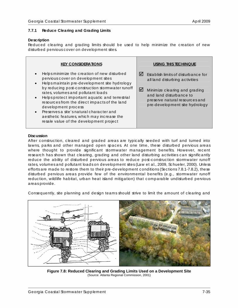
7.7.1 Reduce Clearing and Grading Limits Description Reduced clearing and grading limits should be used to help minimize the creation of new disturbed pervious cover on development sites.
KEY CONSIDERATIONS
Helps minimize the creation of new disturbed
pervious cover on development sites Helps maintain pre-development site hydrology
by reducing post-construction stormwater runoff rates, volumes and pollutant loads
Helps protect important aquatic and terrestrial resources from the direct impacts of the land development process
Preserves a site’s natural character and aesthetic features, which may increase the resale value of the development project
USING THIS TECHINQUE
Establish limits of disturbance for
all land disturbing activities Minimize clearing and grading
and land disturbance to preserve natural resources and pre-development site hydrology
Discussion After construction, cleared and graded areas are typically seeded with turf and turned into lawns, parks and other managed open spaces. At one time, these disturbed pervious areas where thought to provide significant stormwater management benefits. However, recent research has shown that clearing, grading and other land disturbing activities can significantly reduce the ability of disturbed pervious areas to reduce post-construction stormwater runoff rates, volumes and pollutant loads on development sites (Law et al., 2009, Schueler, 2000). Unless efforts are made to restore them to their pre-development conditions (Sections 7.8.1-7.8.2), these disturbed pervious areas provide few of the environmental benefits (e.g., stormwater runoff reduction, wildlife habitat, urban heat island mitigation) that comparable undisturbed pervious areas provide. Consequently, site planning and design teams should strive to limit the amount of clearing and
Figure 7.8: Reduced Clearing and Grading Limits Used on a Development Site (Source: Atlanta Regional Commission, 2001)
Georgia Coastal Stormwater Supplement 7-35

Georgia Coastal Stormwater Supplement April 2009
grading that takes place on a development site (Figure 7.8). Doing so will help preserve pre-development site hydrology and reduce post-construction stormwater runoff rates, volumes and pollutant loads. Methods that site planning and design teams can use to reduce clearing and grading limits on a development site include:
Protecting primary and secondary conservation areas (Section 7.6) Preserving smaller undisturbed natural areas, including stands of trees and other
vegetation Using construction equipment and techniques that will help reduce land disturbance Delineating, on all development plans, the smallest possible area that requires clearing
and grading on the development site; all delineated limits of disturbance should reflect the needs of the construction equipment and techniques that will be used on the development site
Stormwater Management “Credits” Although reducing clearing and grading can be thought of as a “self-crediting” stormwater management technique (i.e., it implicitly reduces post-construction stormwater runoff rates, volumes and pollutant loads), it is important not to overlook the valuable stormwater management benefits that this better site design technique provides. Consequently, it has been assigned quantifiable stormwater management “credits” that can be used when calculating the SWM Criteria that apply to a development site:
Stormwater Runoff Reduction: Subtract 50% of any undisturbed pervious areas from the total site area when calculating the runoff reduction volume (RRv) that applies to a development site.
Water Quality Protection: Subtract 50% of any undisturbed pervious areas from the total
site area when calculating the runoff reduction volume (RRv) that applies to a development site.
Aquatic Resource Protection: Assume that the post-development hydrologic conditions
of any undisturbed pervious areas are equivalent to the pre-development hydrologic conditions for those same areas.
Overbank Flood Protection: Assume that the post-development hydrologic conditions of
any undisturbed pervious areas are equivalent to the pre-development hydrologic conditions for those same areas.
Extreme Flood Protection: Assume that the post-development hydrologic conditions of
any undisturbed pervious areas are equivalent to the pre-development hydrologic conditions for those same areas.
In order to be eligible for these “credits,” it is recommended that undisturbed pervious areas satisfy the planning and design criteria outlined below. Planning and Design Criteria It is recommended that undisturbed pervious areas meet all of the following criteria to be eligible for the stormwater management “credits” described above:
Georgia Coastal Stormwater Supplement 7-36
Georgia Coastal Stormwater Supplement April 2009
General Planning and Design Criteria Undisturbed pervious areas should not be disturbed before, during or after construction
(except for temporary disturbances associated with incidental utility construction, restoration activities or removal of invasive vegetation).
Undisturbed pervious areas should be clearly identified on all development plans. Limits of disturbance around all undisturbed pervious areas should be clearly marked on all development plans and should be delineated with temporary fencing prior to the start of land disturbing activities.
A long-term vegetation management plan should be developed for all undisturbed pervious areas. The plan should clearly specify how the area will be maintained in an undisturbed, natural state over time. Turf management is not considered to be an acceptable form of vegetation management. Consequently, only pervious areas that remain in an undisturbed, natural state are eligible for this “credit” (i.e., pervious areas consisting of managed turf are not eligible for this “credit”).
Georgia Coastal Stormwater Supplement 7-37

Georgia Coastal Stormwater Supplement April 2009
THIS PAGE INTENTIONALLY LEFT BLANK
Georgia Coastal Stormwater Supplement 7-38

Georgia Coastal Stormwater Supplement April 2009
7.7.2 Reduce Roadway Lengths and Widths Description Reduced roadway lengths and widths should used to help reduce the creation of new impervious cover on development sites.
KEY CONSIDERATIONS
Helps minimize the creation of new impervious
cover on development sites Helps maintain pre-development site hydrology
by reducing post-construction stormwater runoff rates, volumes and pollutant loads
Reduces costs associated with roadway construction and maintenance
USING THIS TECHINQUE
Consider alternative site designs
that reduce overall street length Minimize roadway width by using
narrower street designs
Discussion Reduced roadway lengths and widths (Figure 7.9) can be used to help minimize the creation of new impervious cover and reduce post-construction stormwater runoff rates, volumes and pollutant loads on development sites. Consequently, site planning and design teams are encouraged to minimize roadway lengths and widths on a development site. Since there is no single site design technique that is guaranteed to minimize street length on a development site, site planning and design teams are encouraged to consider alternative site layouts to see how much total roadway pavement they require. Generally, compact site designs that make use of smaller lot sizes and reduced setbacks and frontages (Section 7.7.9) help reduce overall street lengths on development sites. Consequently, site planning and design teams are encouraged to create site designs that include a large number of small lots located off of a few main roadways, rather than a small number of large lots located off of a complex network of local roads. In addition to minimizing street length on development sites, site planning and design teams are also encouraged to reduce street widths to the minimum needed to support travel, on-street parking and emergency, maintenance and service vehicle access. Figure 7.10 shows some potential design options for roadways with reduced widths. Many times, on-street parking can be reduced to one lane or eliminated altogether on local cul-de-sac and two-way loop roads. Designing one-way single-lane loop roads is another effective way to reduce the width of local roadways that will see lower average daily traffic volumes. If roadway lengths and widths cannot be minimized on a development site, site planning and design teams are encouraged to consider using grass channels (Section 7.8.7) or swales (Section
Figure 7.9: Reduced Street Width Used on a Residential Development Site
(Source: Center for Watershed Protection)
Georgia Coastal Stormwater Supplement 7-39

Georgia Coastal Stormwater Supplement April 2009
8.6.6) to “receive” roadway runoff. In these situations, site planning and design teams may also want to consider the use of alternative paving surfaces, such as pervious concrete and permeable pavers, for roadway construction. Although permeable pavement is generally more expensive to install than conventional pavement (e.g., asphalt, concrete), it can provide measurable reductions in post-construction stormwater runoff rates, volumes and pollutant loads, which can reduce the need for larger and more costly stormwater management practices, such as wet ponds and stormwater wetlands, on a development site. For additional information about the use of permeable pavement on development sites, see Section 7.8.4. Stormwater Management “Credits” Reducing roadway lengths and widths on a development site can be thought of as a “self-crediting” stormwater management technique. Consequently, it has not been assigned any additional stormwater management “credits” beyond the implicit “credits” outlined below:
Stormwater Runoff Reduction: “Self-crediting,” in that minimizing the creation of new impervious cover results in a lower volumetric runoff coefficient (Rv) and, consequently, a lower runoff reduction volume (RRv) on a development site.
Water Quality Protection: “Self-crediting,” in that minimizing the creation of new
impervious cover results in a lower volumetric runoff coefficient (Rv) and, consequently, a lower runoff reduction volume (RRv) on a development site.
Aquatic Resource Protection: “Self-crediting,” in that minimizing the creation of new
impervious cover results in a lower curve number (CN) and, consequently, a lower aquatic resource protection volume (ARPv) on a development site.
Overbank Flood Protection: “Self-crediting,” in that minimizing the creation of new
impervious cover results in a lower curve number (CN) and, consequently, a lower overbank peak discharge (Qp25) on a development site.
Figure 7.10: Potential Design Options for Reduced Roadway Widths (Source: Atlanta Regional Commission, 2001)
Georgia Coastal Stormwater Supplement 7-40

Georgia Coastal Stormwater Supplement April 2009
Extreme Flood Protection: “Self-crediting,” in that minimizing the creation of new impervious cover results in a lower curve number (CN) and, consequently, a lower extreme peak discharge (Qp100) on a development site.
Georgia Coastal Stormwater Supplement 7-41

Georgia Coastal Stormwater Supplement April 2009
THIS PAGE INTENTIONALLY LEFT BLANK
Georgia Coastal Stormwater Supplement 7-42
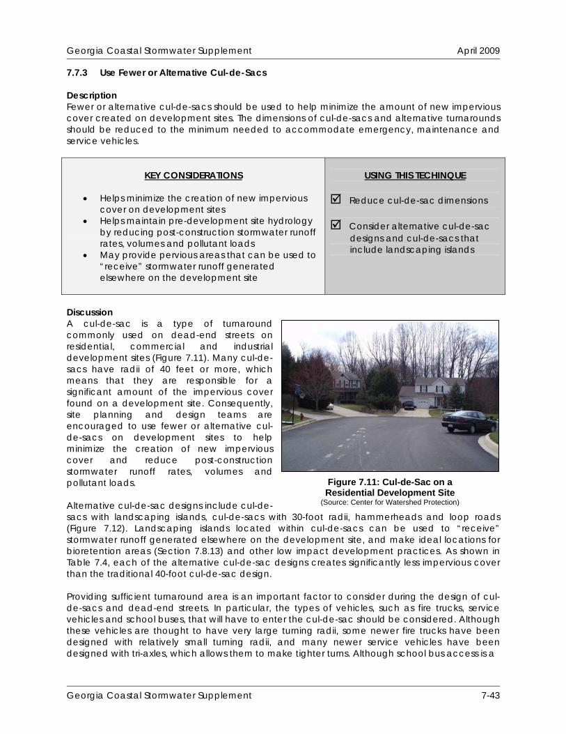
Georgia Coastal Stormwater Supplement April 2009
7.7.3 Use Fewer or Alternative Cul-de-Sacs Description Fewer or alternative cul-de-sacs should be used to help minimize the amount of new impervious cover created on development sites. The dimensions of cul-de-sacs and alternative turnarounds should be reduced to the minimum needed to accommodate emergency, maintenance and service vehicles.
KEY CONSIDERATIONS
Helps minimize the creation of new impervious
cover on development sites Helps maintain pre-development site hydrology
by reducing post-construction stormwater runoff rates, volumes and pollutant loads
May provide pervious areas that can be used to “receive” stormwater runoff generated elsewhere on the development site
USING THIS TECHINQUE
Reduce cul-de-sac dimensions
Consider alternative cul-de-sac
designs and cul-de-sacs that include landscaping islands
Discussion A cul-de-sac is a type of turnaround commonly used on dead-end streets on residential, commercial and industrial development sites (Figure 7.11). Many cul-de-sacs have radii of 40 feet or more, which means that they are responsible for a significant amount of the impervious cover found on a development site. Consequently, site planning and design teams are encouraged to use fewer or alternative cul-de-sacs on development sites to help minimize the creation of new impervious cover and reduce post-construction stormwater runoff rates, volumes and pollutant loads. Alternative cul-de-sac designs include cul-de- sacs with landscaping islands, cul-de-sacs with 30-foot radii, hammerheads and loop roads (Figure 7.12). Landscaping islands located within cul-de-sacs can be used to “receive” stormwater runoff generated elsewhere on the development site, and make ideal locations for bioretention areas (Section 7.8.13) and other low impact development practices. As shown in Table 7.4, each of the alternative cul-de-sac designs creates significantly less impervious cover than the traditional 40-foot cul-de-sac design. Providing sufficient turnaround area is an important factor to consider during the design of cul-de-sacs and dead-end streets. In particular, the types of vehicles, such as fire trucks, service vehicles and school buses, that will have to enter the cul-de-sac should be considered. Although these vehicles are thought to have very large turning radii, some newer fire trucks have been designed with relatively small turning radii, and many newer service vehicles have been designed with tri-axles, which allows them to make tighter turns. Although school bus access is a
Figure 7.11: Cul-de-Sac on a Residential Development Site
(Source: Center for Watershed Protection)
Georgia Coastal Stormwater Supplement 7-43

Georgia Coastal Stormwater Supplement April 2009
Table 7.4: Impervious Cover Created by Various Turnaround Options
(Source: CWP, 1998, Schueler, 1995)
Turnaround Option Impervious Cover (SF)
40 ft radius cul-de-sac 5,024 40 ft radius cul-de-sac with landscaped island 4,397 30 ft radius cul-de-sac 2,826 30 ft radius cul-de-sac with landscaped island 2,512 60 ft by 20 ft T-shaped turnaround 1,250 concern, many school bus drivers choose not to enter individual cul-de-sacs and instead choose to stay on the main roadways that pass through residential developments, which altogether alleviates any concerns over school bus access. Stormwater Management “Credits” Using fewer or alternative cul-de-sacs on a development site can be thought of as a “self-crediting” stormwater management technique. Consequently, it has not been assigned any additional stormwater management “credits” beyond the implicit “credits” outlined below:
Stormwater Runoff Reduction: “Self-crediting,” in that minimizing the creation of new impervious cover results in a lower volumetric runoff coefficient (Rv) and, consequently, a lower runoff reduction volume (RRv) on a development site.
Water Quality Protection: “Self-crediting,” in that minimizing the creation of new
impervious cover results in a lower volumetric runoff coefficient (Rv) and, consequently, a lower runoff reduction volume (RRv) on a development site.
Aquatic Resource Protection: “Self-crediting,” in that minimizing the creation of new
impervious cover results in a lower curve number (CN) and, consequently, a lower aquatic resource protection volume (ARPv) on a development site.
Overbank Flood Protection: “Self-crediting,” in that minimizing the creation of new
impervious cover results in a lower curve number (CN) and, consequently, a lower overbank peak discharge (Qp25) on a development site.
Figure 7.12: Alternative Cul-de-Sac Designs (Source: Center for Watershed Protection, 1998)
Georgia Coastal Stormwater Supplement 7-44

Georgia Coastal Stormwater Supplement April 2009
Extreme Flood Protection: “Self-crediting,” in that minimizing the creation of new impervious cover results in a lower curve number (CN) and, consequently, a lower extreme peak discharge (Qp100) on a development site.
Georgia Coastal Stormwater Supplement 7-45

Georgia Coastal Stormwater Supplement April 2009
THIS PAGE INTENTIONALLY LEFT BLANK
Georgia Coastal Stormwater Supplement 7-46

Georgia Coastal Stormwater Supplement April 2009
7.7.4 Reduce Parking Lot Footprints Description Consider reducing the amount of new impervious cover created on development sites by providing compact car spaces, minimizing stall dimensions, incorporating efficient parking lanes, using structured parking facilities and using alternative paving surfaces (e.g., permeable pavement) in parking lots.
KEY CONSIDERATIONS
Helps minimize the creation of new impervious
cover on development sites Helps maintain pre-development site hydrology
by reducing post-construction stormwater runoff rates, volumes and pollutant loads
USING THIS TECHINQUE
Consider alternative parking lot
designs that reduce overall site imperviousness
Consider the use of alternative
paving surfaces
Discussion Parking lots (Figure 7.13) are typically responsible for a significant amount of the impervious cover found on commercial and industrial development sites (CWP, 1998) Consequently, site planning and design teams are encouraged to reduce parking lot footprints to help minimize the creation of new impervious cover and reduce post-construction stormwater runoff rates, volumes and pollutant loads. Techniques that can be used to reduce parking lot footprints on development sites include:
Rethinking parking lot design Minimizing parking stall dimensions Providing compact car parking spaces Using structured parking
es (e.g., permeable pavement)
ach of these techniques is briefly described below.
ethinking Parking Lot Design to provide far more parking spaces than are actually needed on
Using shared parking Using alternative paving surfac
E RParking lots are often designeda daily basis. This problem is exacerbated by the common practice of designing parking lots to provide enough parking spaces to accommodate the highest parking demand experienced during the peak shopping season. By using average parking demand as a basis for parking lot design, instead of peak parking demand, fewer parking spaces (which will still accommodate the parking demand for almost the entire year) and less impervious cover will be created on development sites. Table 7.5 provides examples of the conventional parking requirements
Figure 7.13: Parking Lot on a Commercial Development Site
(Source: Center for Watershed Protection)
Georgia Coastal Stormwater Supplement 7-47
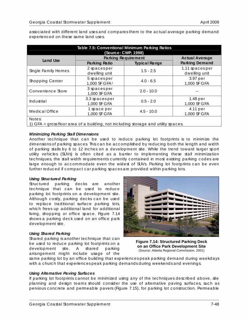
Georgia Coastal Stormwater Supplement April 2009
associated with different land uses and compares them to the actual average parking demand experienced on these same land uses.
Table 7.5: Conventional Minimum Parking Ratios (Source: CWP, 1998) Parking Requirement
Minimizing Parking Stall Dimensions
used to reduce parking lot footprints is to minimize the
sing Structured Parking cks are another
sing Shared Parking her technique that can
riences peak parking de kdays
sing Alternative Paving Surfaces minimized using any of the techniques described above, site
Another technique that can be dimensions of parking spaces. This can be accomplished by reducing both the length and width of parking stalls by 6 to 12 inches on a development site. While the trend toward larger sport utility vehicles (SUVs) is often cited as a barrier to implementing these stall minimization techniques, the stall width requirements currently contained in most existing parking codes are large enough to accommodate even the widest of SUVs. Parking lot footprints can be even further reduced if compact car parking spaces are provided within parking lots. UStructured parking de technique that can be used to reduce parking lot footprints on a development site. Although costly, parking decks can be used to replace traditional surface parking lots, which frees up additional land for additional living, shopping or office space. Figure 7.14 shows a parking deck used on an office park development site. UShared parking is anotbe used to reduce parking lot footprints on a development site. A shared parking arrangement might include usage of the same parking lot by an office building that expewith a church that experiences peak parking demands during weekends and evenings.
mand during wee
UIf parking lot footprints cannot beplanning and design teams should consider the use of alternative paving surfaces, such as pervious concrete and permeable pavers (Figure 7.15), for parking lot construction. Permeable
Land Use Parking Ratio TypicaActual Average
l Range Parking Demand 2 spaces per dwelling unit 1.5 - 2.5 1.11 spaces per
dwelling unit Single Family Homes
Shopping Center 4.0 - 6.5 1, 5 spaces per 1,000 SF GFA1
3.97 per 000 SF GFA
Convenience Store 2.0 - 10.0 3 spaces per 1,000 SF GFA --
Industrial 3 0.5 - 2.0 1.48 per 1,
.3 spaces per 1,000 SF GFA 000 SF GFA
Medical Office 4.5 - 10.0 1, 1 space per 1,000 SF GFA
4.11 per 000 SF GFA
Notes: 1) GFA = gross floor area of a building, not including storage and utility spaces.
Figure 7.14: Structured Parking Deck on an Office Park Development Site (Source: Atlanta Regional Commission, 2001)
Georgia Coastal Stormwater Supplement 7-48
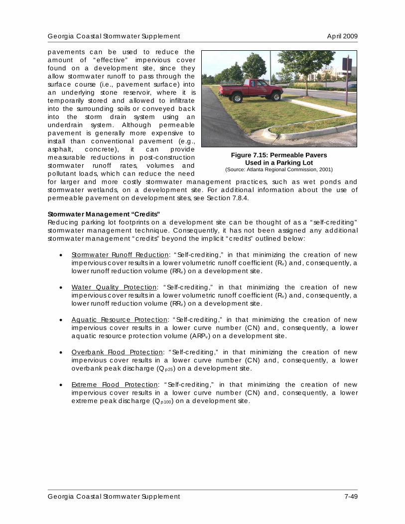
Georgia Coastal Stormwater Supplement April 2009
pavements can be used to reduce the amount of “effective” impervious cover found on a development site, since they allow stormwater runoff to pass through the surface course (i.e., pavement surface) into an underlying stone reservoir, where it is temporarily stored and allowed to infiltrate into the surrounding soils or conveyed back into the storm drain system using an underdrain system. Although permeable pavement is generally more expensive to install than conventional pavement (e.g., asphalt, concrete), it can provide measurable reductions in post-construction stormwater runoff rates, volumes and pollutant loads, which can reduce the need for larger and more costly stormwater management practices, such as wet ponds and stormwater wetlands, on a development site. For additional information about the use of permeable pavement on development sites, see Section 7.8.4.
Figure 7.15: Permeable Pavers Used in a Parking Lot
(Source: Atlanta Regional Commission, 2001)
Stormwater Management “Credits” opment site can be thought of as a “self-crediting”
Stormwater Runoff Reduction
Reducing parking lot footprints on a develstormwater management technique. Consequently, it has not been assigned any additional stormwater management “credits” beyond the implicit “credits” outlined below:
: “Self-crediting,” in that minimizing the creation of new
Water Quality Protection
impervious cover results in a lower volumetric runoff coefficient (Rv) and, consequently, a lower runoff reduction volume (RRv) on a development site.
: “Self-crediting,” in that minimizing the creation of new
Aquatic Resource Protection
impervious cover results in a lower volumetric runoff coefficient (Rv) and, consequently, a lower runoff reduction volume (RRv) on a development site.
: “Self-crediting,” in that minimizing the creation of new
Overbank Flood Protection
impervious cover results in a lower curve number (CN) and, consequently, a lower aquatic resource protection volume (ARPv) on a development site.
: “Self-crediting,” in that minimizing the creation of new
Extreme Flood Protection
impervious cover results in a lower curve number (CN) and, consequently, a lower overbank peak discharge (Qp25) on a development site.
: “Self-crediting,” in that minimizing the creation of new
impervious cover results in a lower curve number (CN) and, consequently, a lower extreme peak discharge (Qp100) on a development site.
Georgia Coastal Stormwater Supplement 7-49

Georgia Coastal Stormwater Supplement April 2009
THIS PAGE INTENTIONALLY LEFT BLANK
Georgia Coastal Stormwater Supplement 7-50
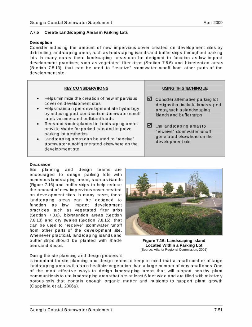
Georgia Coastal Stormwater Supplement April 2009
7.7.5 Create Landscaping Areas in Parking Lots Description Consider reducing the amount of new impervious cover created on development sites by distributing landscaping areas, such as landscaping islands and buffer strips, throughout parking lots. In many cases, these landscaping areas can be designed to function as low impact development practices, such as vegetated filter strips (Section 7.8.6) and bioretention areas (Section 7.8.13), that can be used to “receive” stormwater runoff from other parts of the development site.
KEY CONSIDERATIONS
Helps minimize the creation of new impervious
cover on development sites Helps maintain pre-development site hydrology
by reducing post-construction stormwater runoff rates, volumes and pollutant loads
Trees and shrubs planted in landscaping areas provide shade for parked cars and improve parking lot aesthetics
Landscaping areas can be used to “receive” stormwater runoff generated elsewhere on the development site
USING THIS TECHINQUE
Consider alternative parking lot
designs that include landscaped areas, such as landscaping islands and buffer strips
Use landscaping areas to
“receive” stormwater runoff generated elsewhere on the development site
Discussion Site planning and design teams are encouraged to design parking lots with numerous landscaping areas, such as islands (Figure 7.16) and buffer strips, to help reduce the amount of new impervious cover created on development sites. In many cases, these landscaping areas can be designed to function as low impact development practices, such as vegetated filter strips (Section 7.8.6), bioretention areas (Section 7.8.13) and dry swales (Section 7.8.15), that can be used to “receive” stormwater runoff from other parts of the development site. Whenever practical, landscaping islands and buffer strips should be planted with shade trees and shrubs. During the site planning and design process, it is important for site planning and design teams to keep in mind that a small number of large landscaping areas will sustain healthier vegetation than a large number of very small ones. One of the most effective ways to design landscaping areas that will support healthy plant communities is to use landscaping areas that are at least 6 feet wide and are filled with relatively porous soils that contain enough organic matter and nutrients to support plant growth (Cappiella et al., 2006a).
Figure 7.16: Landscaping Island Located Within a Parking Lot
(Source: Atlanta Regional Commission, 2001)
Georgia Coastal Stormwater Supplement 7-51

Georgia Coastal Stormwater Supplement April 2009
Stormwater Management “Credits” Creating landscaping areas in parking lots can be thought of as a “self-crediting” stormwater management technique. Consequently, it has not been assigned any additional stormwater management “credits” beyond the implicit “credits” outlined below:
Stormwater Runoff Reduction: “Self-crediting,” in that minimizing the creation of new impervious cover results in a lower volumetric runoff coefficient (Rv) and, consequently, a lower runoff reduction volume (RRv) on a development site.
Water Quality Protection: “Self-crediting,” in that minimizing the creation of new
impervious cover results in a lower volumetric runoff coefficient (Rv) and, consequently, a lower runoff reduction volume (RRv) on a development site.
Aquatic Resource Protection: “Self-crediting,” in that minimizing the creation of new
impervious cover results in a lower curve number (CN) and, consequently, a lower aquatic resource protection volume (ARPv) on a development site.
Overbank Flood Protection: “Self-crediting,” in that minimizing the creation of new
impervious cover results in a lower curve number (CN) and, consequently, a lower overbank peak discharge (Qp25) on a development site.
Extreme Flood Protection: “Self-crediting,” in that minimizing the creation of new
impervious cover results in a lower curve number (CN) and, consequently, a lower extreme peak discharge (Qp100) on a development site.
Georgia Coastal Stormwater Supplement 7-52

Georgia Coastal Stormwater Supplement April 2009
7.7.6 Reduce Driveway Lengths and Widths Description Reduced driveway lengths and widths should be used to help reduce the creation of new impervious cover on development sites.
KEY CONSIDERATIONS
Helps minimize the creation of new impervious
cover on development sites Helps maintain pre-development site hydrology
by reducing post-construction stormwater runoff rates, volumes and pollutant loads
Reduces costs associated with driveway construction and maintenance
USING THIS TECHINQUE
Consider alternative site designs
that reduce overall driveway length
Minimize driveway width by using
narrower or shared sidewalk designs
Discussion Given that as much as 20% of the impervious cover found in a typical residential subdivision consists of sidewalks and driveways (CWP, 1998), site planning and design teams are encouraged to reduce driveway lengths and widths on development sites. Methods that can be used to reduce driveway lengths and widths include:
Evaluating alternative site layouts to see how much total driveway pavement they will require
Reducing setbacks and frontages (Section 7.7.9)
Using shared driveways (Figure 7.17) Figure 7.17: Shared Driveway on a Residential Development Site Using narrower driveway widths
(Source: Center for Watershed Protection) If driveway lengths and widths cannot be minimized using the methods described above, site planning and design teams should consider using alternative or permeable surfaces, such as crushed rock, crushed shells or permeable pavement (Section 7.8.4), for driveway construction. Stormwater Management “Credits” Reducing driveway lengths and widths on a development site can be thought of as a “self-crediting” stormwater management technique. Consequently, it has not been assigned any additional stormwater management “credits” beyond the implicit “credits” outlined below:
Stormwater Runoff Reduction: “Self-crediting,” in that minimizing the creation of new impervious cover results in a lower volumetric runoff coefficient (Rv) and, consequently, a lower runoff reduction volume (RRv) on a development site.
Georgia Coastal Stormwater Supplement 7-53

Georgia Coastal Stormwater Supplement April 2009
Water Quality Protection: “Self-crediting,” in that minimizing the creation of new impervious cover results in a lower volumetric runoff coefficient (Rv) and, consequently, a lower runoff reduction volume (RRv) on a development site.
Aquatic Resource Protection: “Self-crediting,” in that minimizing the creation of new
impervious cover results in a lower curve number (CN) and, consequently, a lower aquatic resource protection volume (ARPv) on a development site.
Overbank Flood Protection: “Self-crediting,” in that minimizing the creation of new
impervious cover results in a lower curve number (CN) and, consequently, a lower overbank peak discharge (Qp25) on a development site.
Extreme Flood Protection: “Self-crediting,” in that minimizing the creation of new
impervious cover results in a lower curve number (CN) and, consequently, a lower extreme peak discharge (Qp100) on a development site.
Georgia Coastal Stormwater Supplement 7-54

Georgia Coastal Stormwater Supplement April 2009
7.7.7 Reduce Sidewalk Lengths and Widths Description Reduced sidewalk lengths and widths should be used to help reduce the creation of new impervious cover on development sites.
KEY CONSIDERATIONS
Helps minimize the creation of new impervious
cover on development sites Helps maintain pre-development site hydrology
by reducing post-construction stormwater runoff rates, volumes and pollutant loads
Reduces costs associated with sidewalk construction and maintenance
USING THIS TECHINQUE
Consider alternative site designs
that reduce overall sidewalk length
Minimize sidewalk width by using
narrower or alternative sidewalk designs
Discussion Given that as much as 20% of the impervious cover found in a typical residential subdivision consists of sidewalks and driveways (CWP, 1998), site planning and design teams are encouraged to reduce sidewalk lengths and widths on development sites. Methods that can be used to reduce sidewalk lengths and widths include:
Evaluating alternative site layouts to see how much total sidewalk pavement they will require
Reducing setbacks and frontages (Section 7.7.9)
Locating sidewalks on only one side of the street (Figure 7.18)
Using sidewalk widths of six feet in areas that will see high foot traffic and sidewalk widths of four feet in areas that will see less use
If sidewalk lengths and widths cannot be minimized using the methods described above, site planning and design teams should consider using alternative or permeable surfaces, such as crushed rock, crushed shells or permeable pavement (Section 7.8.4), for sidewalk construction. Stormwater Management “Credits” Reducing sidewalks lengths and widths on a development site can be thought of as a “self-crediting” stormwater management technique. Consequently, it has not been assigned any additional stormwater management “credits” beyond the implicit “credits” outlined below:
Stormwater Runoff Reduction: “Self-crediting,” in that minimizing the creation of new impervious cover results in a lower volumetric runoff coefficient (Rv) and, consequently, a lower runoff reduction volume (RRv) on a development site.
Figure 7.18: Residential Development Site with Sidewalks on One Side of the Street
(Source: Center for Watershed Protection)
Georgia Coastal Stormwater Supplement 7-55

Georgia Coastal Stormwater Supplement April 2009
Water Quality Protection: “Self-crediting,” in that minimizing the creation of new impervious cover results in a lower volumetric runoff coefficient (Rv) and, consequently, a lower runoff reduction volume (RRv) on a development site.
Aquatic Resource Protection: “Self-crediting,” in that minimizing the creation of new
impervious cover results in a lower curve number (CN) and, consequently, a lower aquatic resource protection volume (ARPv) on a development site.
Overbank Flood Protection: “Self-crediting,” in that minimizing the creation of new
impervious cover results in a lower curve number (CN) and, consequently, a lower overbank peak discharge (Qp25) on a development site.
Extreme Flood Protection: “Self-crediting,” in that minimizing the creation of new
impervious cover results in a lower curve number (CN) and, consequently, a lower extreme peak discharge (Qp100) on a development site.
Georgia Coastal Stormwater Supplement 7-56
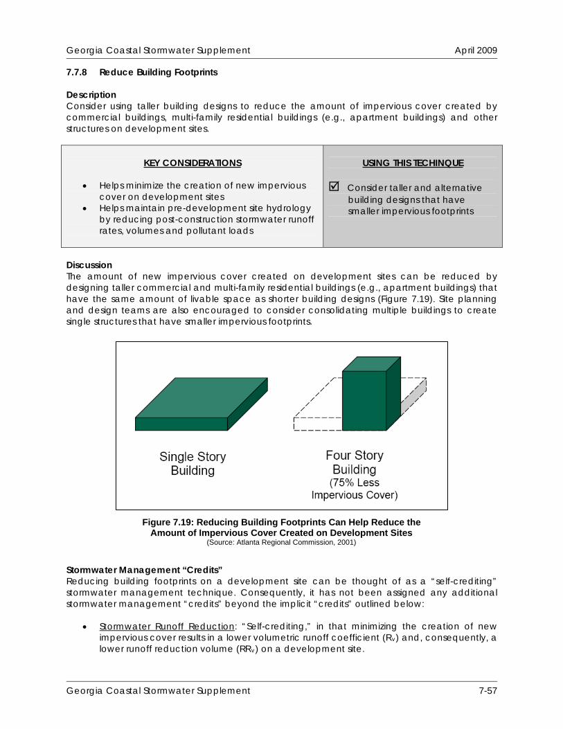
Georgia Coastal Stormwater Supplement April 2009
7.7.8 Reduce Building Footprints Description Consider using taller building designs to reduce the amount of impervious cover created by commercial buildings, multi-family residential buildings (e.g., apartment buildings) and other structures on development sites.
KEY CONSIDERATIONS
Helps minimize the creation of new impervious
cover on development sites Helps maintain pre-development site hydrology
by reducing post-construction stormwater runoff rates, volumes and pollutant loads
USING THIS TECHINQUE
Consider taller and alternative
building designs that have smaller impervious footprints
Discussion The amount of new impervious cover created on development sites can be reduced by designing taller commercial and multi-family residential buildings (e.g., apartment buildings) that have the same amount of livable space as shorter building designs (Figure 7.19). Site planning and design teams are also encouraged to consider consolidating multiple buildings to create single structures that have smaller impervious footprints. Stormwater Management “Credits” Reducing building footprints on a development site can be thought of as a “self-crediting” stormwater management technique. Consequently, it has not been assigned any additional stormwater management “credits” beyond the implicit “credits” outlined below:
Stormwater Runoff Reduction: “Self-crediting,” in that minimizing the creation of new impervious cover results in a lower volumetric runoff coefficient (Rv) and, consequently, a lower runoff reduction volume (RRv) on a development site.
Source: ARC, 2001
Figure 7.19: Reducing Building Footprints Can Help Reduce the Amount of Impervious Cover Created on Development Sites
(Source: Atlanta Regional Commission, 2001)
Georgia Coastal Stormwater Supplement 7-57

Georgia Coastal Stormwater Supplement April 2009
Water Quality Protection: “Self-crediting,” in that minimizing the creation of new impervious cover results in a lower volumetric runoff coefficient (Rv) and, consequently, a lower runoff reduction volume (RRv) on a development site.
Aquatic Resource Protection: “Self-crediting,” in that minimizing the creation of new
impervious cover results in a lower curve number (CN) and, consequently, a lower aquatic resource protection volume (ARPv) on a development site.
Overbank Flood Protection: “Self-crediting,” in that minimizing the creation of new
impervious cover results in a lower curve number (CN) and, consequently, a lower overbank peak discharge (Qp25) on a development site.
Extreme Flood Protection: “Self-crediting,” in that minimizing the creation of new
impervious cover results in a lower curve number (CN) and, consequently, a lower extreme peak discharge (Qp100) on a development site.
Georgia Coastal Stormwater Supplement 7-58
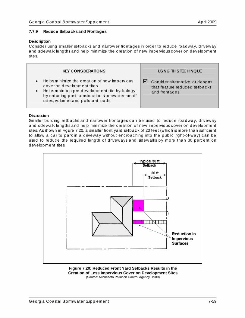
Georgia Coastal Stormwater Supplement April 2009
7.7.9 Reduce Setbacks and Frontages Description Consider using smaller setbacks and narrower frontages in order to reduce roadway, driveway and sidewalk lengths and help minimize the creation of new impervious cover on development sites.
KEY CONSIDERATIONS
Helps minimize the creation of new impervious
cover on development sites Helps maintain pre-development site hydrology
by reducing post-construction stormwater runoff rates, volumes and pollutant loads
USING THIS TECHINQUE
Consider alternative lot designs
that feature reduced setbacks and frontages
Discussion Smaller building setbacks and narrower frontages can be used to reduce roadway, driveway and sidewalk lengths and help minimize the creation of new impervious cover on development sites. As shown in Figure 7.20, a smaller front yard setback of 20 feet (which is more than sufficient to allow a car to park in a driveway without encroaching into the public right-of-way) can be used to reduce the required length of driveways and sidewalks by more than 30 percent on development sites.
Figure 7.20: Reduced Front Yard Setbacks Results in the Creation of Less Impervious Cover on Development Sites
(Source: Minnesota Pollution Control Agency, 1989)
Georgia Coastal Stormwater Supplement 7-59

Georgia Coastal Stormwater Supplement April 2009
Smaller side yard setbacks and narrower frontages can also help minimize the creation of new impervious cover on development sites. Both of these techniques can be used help create more compact site designs that require smaller amounts of roadway, driveway and sidewalk pavement. Figure 7.21 illustrates how reduced side yard setbacks and narrower frontages can be used on residential development sites.
Smaller setbacks and narrower frontages also allow site planning and design teams to use flexible lot shapes (Figure 7.22) and create conservation developments (Box 6.1), which provide a host of environmental benefits that are typically more difficult to achieve on more conventional development projects. Conservation developments, also known as open space developments or cluster developments, provide for better natural resource protection on development sites and inherently limit increases in site imperviousness, sometimes by as much as 40 to 60 percent (CWP, 1998).
Figure 7.22: Alternative Lot Designs (Source: Center for Watershed Protection, 1998)
Figure 7.21: Reduced Side Yard Setbacks and Narrower Frontages Used on Residential Development Sites
(Source: Atlanta Regional Commission, 2001)
Georgia Coastal Stormwater Supplement 7-60
Georgia Coastal Stormwater Supplement April 2009
Stormwater Management “Credits” a development site can be thought of as a “self-crediting”
Stormwater Runoff Reduction
Reducing setbacks and frontages onstormwater management technique. Consequently, it has not been assigned any additional stormwater management “credits” beyond the implicit “credits” outlined below:
: “Self-crediting,” in that minimizing the creation of new
Stormwater Runoff Reduction
impervious cover results in a lower volumetric runoff coefficient (Rv) and, consequently, a lower runoff reduction volume (RRv) on a development site.
: “Self-crediting,” in that minimizing the creation of new
Water Quality Protection
impervious cover results in a lower volumetric runoff coefficient (Rv) and, consequently, a lower runoff reduction volume (RRv) on a development site.
: “Self-crediting,” in that minimizing the creation of new
Aquatic Resource Protection
impervious cover results in a lower volumetric runoff coefficient (Rv) and, consequently, a lower runoff reduction volume (RRv) on a development site.
: “Self-crediting,” in that minimizing the creation of new
Overbank Flood Protection
impervious cover results in a lower curve number (CN) and, consequently, a lower aquatic resource protection volume (ARPv) on a development site.
: “Self-crediting,” in that minimizing the creation of new
Extreme Flood Protection
impervious cover results in a lower curve number (CN) and, consequently, a lower overbank peak discharge (Qp25) on a development site.
: “Self-crediting,” in that minimizing the creation of new
impervious cover results in a lower curve number (CN) and, consequently, a lower extreme peak discharge (Qp100) on a development site.
Georgia Coastal Stormwater Supplement 7-61

Georgia Coastal Stormwater Supplement April 2009
Georgia Coastal Stormwater Supplement 7-62
THIS PAGE INTENTIONALLY LEFT BLANK
Georgia Coastal Stormwater Supplement April 2009
7.8 Low Impact Development Practice Profile Sheets This Section contains profile sheets that provide information about the low impact development practices that are recommended for use in coastal Georgia. The profile sheets describe each of the low impact development practices, discuss how to properly apply and design them on development sites and provide information about how they can be used to help satisfy the SWM Criteria presented in this CSS. The low impact development practices profiled in this Section include: Alternatives to Disturbed Pervious Surfaces
7.8.1 Soil Restoration 7.8.2 Site Reforestation/Revegetation
Alternatives to Impervious Surfaces
7.8.3 Green Roofs 7.8.4 Permeable Pavement
“Receiving” Low Impact Development Practices
7.8.5 Undisturbed Pervious Areas 7.8.6 Vegetated Filter Strips 7.8.7 Grass Channels 7.8.8 Simple Downspout Disconnection 7.8.9 Rain Gardens 7.8.10 Stormwater Planters 7.8.11 Dry Wells 7.8.12 Rainwater Harvesting 7.8.13 Bioretention Areas 7.8.14 Infiltration Practices 7.8.15 Dry Swales
Georgia Coastal Stormwater Supplement 7-63

Georgia Coastal Stormwater Supplement April 2009
Georgia Coastal Stormwater Supplement 7-64
THIS PAGE INTENTIONALLY LEFT BLANK

Georgia Coastal Stormwater Supplement April 2009
7.8.1 Soil Restoration Description Soil restoration refers to the process of tilling and adding compost and other amendments to soils to restore them to their pre-development conditions, which improves their ability to reduce post-construction stormwater runoff rates, volumes and pollutant loads. The soil restoration process can be used to improve the hydrologic conditions of pervious areas that have been disturbed by clearing, grading and other land disturbing activities. It can also be used to increase the reduction in stormwater runoff rates, volumes and pollutant loads provided by other low impact development practices.
STORMWATER MANAGEMENT
“CREDITS”
Runoff Reduction Water Quality Protection Aquatic Resource Protection Overbank Flood Protection Extreme Flood Protection = practice has been assigned quantifiable stormwater management “credits” that can be used to address this SWM Criteria
KEY CONSIDERATIONS
DESIGN CRITERIA:
Ideal for use in pervious areas that have been disturbed by clearing, grading and other land disturbing activities
To properly restore disturbed pervious areas, soil amendments should be added to existing soils to a depth of 18 inches until an organic matter content of 8% to 12% is obtained
Restored pervious areas should be protected from future land disturbing activities
BENEFITS:
Helps restore pre-development hydrology on development sites and reduces post-construction stormwater runoff rates, volumes and pollutant loads
Promotes plant growth and improves plant health, which helps reduce stormwater runoff rates, volumes and pollutant loads
LIMITATIONS:
Should not be used on areas that have slopes of greater than 10%
To help prevent soil erosion, landscaping should be installed immediately after the soil restoration process is complete
SITE APPLICABILITY
Rural Use Suburban Use Urban Use
M Construction Cost L Maintenance L Area Required
STORMWATER MANAGEMENT
PRACTICE PERFORMANCE Runoff Reduction N/A1 - Annual Runoff Volume N/A1 - Runoff Reduction Volume Pollutant Removal N/A1 - Total Suspended Solids N/A1 - Total Phosphorus N/A1 - Total Nitrogen N/A1 - Metals N/A1 - Pathogens 1 = helps restore pre-development hydrology, which implicitly reduces post-construction stormwater runoff rates, volumes and pollutant loads
(Source: http://www.towncountryltd.com)
Georgia Coastal Stormwater Supplement 7-65

Georgia Coastal Stormwater Supplement April 2009
Discussion Soil restoration refers to the process of tilling and adding compost and other amendments to soils to restore them to their pre-development conditions. It is ideal for use on lawns and other pervious areas that have been disturbed by clearing, grading and other land disturbing activities. Organic compost (Figure 7.23) and other amendments can be tilled into soils in these areas to help create healthier, uncompacted soil matrices that have enough organic matter to support a diverse community of native trees, shrubs and other herbaceous plants. Soil restoration can also be used to increase the stormwater management benefits provided by other low impact development practices, such as svegetated filter strips (Section 7.8.6), grass channels (Section 7.8.7) and simple downspout disconnection (Section 7.8.8), on sites that have soils with low permeabilities (i.e., hydrologic soil group C or D soils). The soil restoration process can be used to help increase soil porosity and improve soil infiltration rates on these sites, which improves the ability of these and other low impact development practices to reduce post-construction stormwater runoff rates, volumes and pollutant loads.
ite reforestation/revegetation (Section 7.8.2),
Stormwater Management “Credits” The Center for Watershed Protection (Hirschman et al., 2008) recently documented the ability of the soil restoration process to reduce annual stormwater runoff volumes and pollutant loads on development sites. Consequently, this low impact development practice has been assigned quantifiable stormwater management “credits” that can be used to help satisfy the SWM Criteria presented in this CSS:
Stormwater Runoff Reduction: Subtract 50% of any restored pervious areas from the total site area and re-calculate the runoff reduction volume (RRv) that applies to the development site.
Water Quality Protection: Subtract 50% of any restored pervious areas from the total site
area and re-calculate the runoff reduction volume (RRv) that applies to the development site.
Aquatic Resource Protection: Assume that the post-development hydrologic conditions
of any restored pervious areas are equivalent to those of open space (e.g., lawns, parks, golf courses) in good condition.
Overbank Flood Protection: Assume that the post-development hydrologic conditions of
any restored pervious areas are equivalent to those of open space (e.g., lawns, parks, golf courses) in good condition.
Extreme Flood Protection: Assume that the post-development hydrologic conditions of
any restored pervious areas are equivalent to those of open space (e.g., lawns, parks, golf courses) in good condition.
Figure 7.23: Organic Compost (Source: http://www.organicgardeninfo.com)
Georgia Coastal Stormwater Supplement 7-66

Georgia Coastal Stormwater Supplement April 2009
In order to be eligible for these “credits,” it is recommended that restored pervious areas satisfy the planning and design criteria outlined below. If any type of vegetation other than managed turf can be planted on a restored pervious area, site planning and design teams are encouraged to combine soil restoration with site reforestation/revegetation (Section 7.8.2) to further reduce post-construction stormwater runoff rates, volumes and pollutant loads. When soil restoration is used to enhance the performance of other low impact development practices (e.g., site reforestation/revegetation, vegetated filter strips, grass channels), it may be “credited” as described in the appropriate low impact development practice profile sheet. Overall Feasibility The criteria listed in Table 7.6 should be evaluated to determine whether or not soil restoration is appropriate for use on a development site.
Table 7.6: Factors to Consider When Evaluating the Overall Feasibility of Using Soil Restoration on a Development Site
Site Characteristic Criteria Drainage Area N/A Area Required No restrictions Slope Maximum 10% in the disturbed pervious area to be restored. Minimum Head N/A Minimum Depth to Water Table
A separation distance of 18 inches is recommended between the surface of a restored pervious area and the top of the water table.
Soils
Pervious areas that have soils with low permeabilities (i.e., hydrologic soil group C or D soils) or that have been disturbed by land disturbing activities are good candidates for soil restoration. Areas that have permeable soils (i.e., hydrologic soil group A or B soils) and that have not been disturbed by land disturbing activities do not need to be restored.
Site Applicability Soil restoration can be used on a wide variety of development sites, including residential, commercial, industrial and institutional development sites in rural, suburban and urban areas. When compared with other low impact development practices, it has a moderate construction cost, a relatively low maintenance burden and requires no additional surface area beyond that which will undergo the soil restoration process. It is ideal for use in pervious areas that have been disturbed by clearing, grading and other land disturbing activities. Planning and Design Criteria It is recommended that the soil restoration process used on a development site meet all of the following criteria to be eligible for the stormwater management “credits” described above: General Planning and Design
To avoid damaging existing root systems, soil restoration should not be performed in areas that fall within the drip line of existing trees.
Compost should be incorporated into existing soils, using a rototiller or similar equipment, to a depth of 18 inches and at an application rate necessary to obtain a final average organic matter content of 8%-12%. Required application rates can be determined using a compost calculator, such as the one provided on the following website: http://www.soilsforsalmon.org/resources.htm.
Georgia Coastal Stormwater Supplement 7-67
Georgia Coastal Stormwater Supplement April 2009
Only well-aged composts that have been composted for a period of at least one year should be used to amend existing soils. Composts should be stable and show no signs of further decomposition.
Composts used to amend existing soils should meet the following specifications (most compost suppliers will be able to provide this information):
o Organic Content Matter: Composts should contain 35%-65% organic matter. o Moisture Content: Composts should have a moisture content of 40%-60%. o Bulk Density: Composts should have an “as-is” bulk density of 40-50 pounds per
cubic foot (lb/cf). In composts that have a moisture content of 40%-60%, this equates to a bulk density range of 450-800 pounds per cubic yard (lb/cy), by dry weight.
o Carbon to Nitrogen (C:N) Ratio: Composts should have a C:N Ratio of less than 25:1.
o pH: Composts should have a pH of 6-8. o Cation Exchange Capacity (CEC): Composts should have a CEC that exceeds 50
milliequivalents (meq) per 100 grams of dry weight. o Foreign Material Content: Composts should contain less than 0.5% foreign
materials (e.g., glass, plastic), by weight. o Pesticide Content: Composts should be pesticide free.
The use of biosolids (except Class 1 biosolids) and composted animal manure to amend existing soils is not recommended.
It is recommended that composts used to amend existing soils be provided by a member of the U.S. Composting Seal of Testing Assurance program. Additional information on the Seal of Testing Assurance program is available on the following website: http://www.compostingcouncil.org.
Landscaping
Vegetation commonly planted on restored pervious areas includes turf, shrubs, trees and other herbaceous vegetation. Although managed turf is most commonly used, site planning and design teams are encouraged to use trees, shrubs and/or other native vegetation to help establish mature native plant communities (e.g., forests) in restored pervious areas.
Methods used to establish vegetative cover within a restored pervious area should achieve at least 75 percent vegetative cover one year after installation.
To help prevent soil erosion and sediment loss, landscaping should be installed immediately after the soil restoration process is complete. Temporary irrigation may be needed to quickly establish vegetative cover on a restored pervious area.
Construction Considerations To help ensure that the soil restoration process is successfully completed on a development site, site planning and design teams should consider the following recommendations:
To help minimize compaction, heavy vehicular and foot traffic should be kept out of all restored pervious areas during and after construction. This can typically be accomplished by clearly delineating soil restoration areas on all development plans and, if necessary, protecting them with temporary construction fencing.
Simple erosion and sediment control measures, such as temporary seeding and erosion control mats, should be used on restored pervious areas that exceed 2,500 square feet in size. If the restored pervious areas will “receive” any stormwater runoff from other portions of the development site, measures should be taken (e.g., silt fence, temporary diversion berm) to prevent it from compromising the soil restoration effort.
Georgia Coastal Stormwater Supplement 7-68

Georgia Coastal Stormwater Supplement April 2009
Test pits or a rod penetrometer can be used to verify that soil amendments have reached a depth of 18 inches.
Construction contracts should contain a replacement warranty that covers at least three growing seasons to help ensure adequate growth and survival of the vegetation planted on a restored pervious area.
Maintenance Requirements Restored pervious areas require some maintenance during the first few months following construction, but typically require very little maintenance after that. Table 7.7 provides a list of the routine maintenance activities typically associated with restored pervious areas.
Table 7.7: Routine Maintenance Activities Typically Associated with Soil Restoration Activity Schedule
Water to promote plant growth and survival. Inspect restored pervious area following rainfall
events. Plant replacement vegetation in any eroded areas.
As Needed (Following Construction)
Inspect restored pervious area for erosion. Plant replacement vegetation in any eroded areas.
Inspect restored pervious area for dead or dying vegetation. Plant replacement vegetation as needed.
Annually (Semi-Annually During First Year)
Additional Resources Stenn, H. 2007. Building Soil: Guidelines and Resources for Implementing Soil Quality and Depth
BMP T5.13 in Washington Department of Ecology (WDOE) Stormwater Management Manual for Western Washington. Public Works Department. Snohomish County, WA. Available Online: http://www.soilsforsalmon.org/resources.htm.
Washington Department of Ecology (WDOE). 2005. “BMP T5.13: Post-Construction Soil Quality
and Depth.” Stormwater Management Manual for Western Washington. Volume 5: Runoff Treatment BMPs. Washington Department of Ecology. Water Quality Program. Available Online: http://www.ecy.wa.gov/programs/wq/stormwater/manual.html.
Pennsylvania Department of Environmental Protection (PA DEP). 2006. “BMP 6.7.3: Soil
Amendment and Restoration.” Pennsylvania Stormwater Best Management Practices Manual. Pennsylvania Department of Environmental Protection. Bureau of Watershed Management. Available Online: http://www.depweb.state.pa.us/watershedmgmt/site/default.asp.
Georgia Coastal Stormwater Supplement 7-69

Georgia Coastal Stormwater Supplement April 2009
THIS PAGE INTENTIONALLY LEFT BLANK
Georgia Coastal Stormwater Supplement 7-70
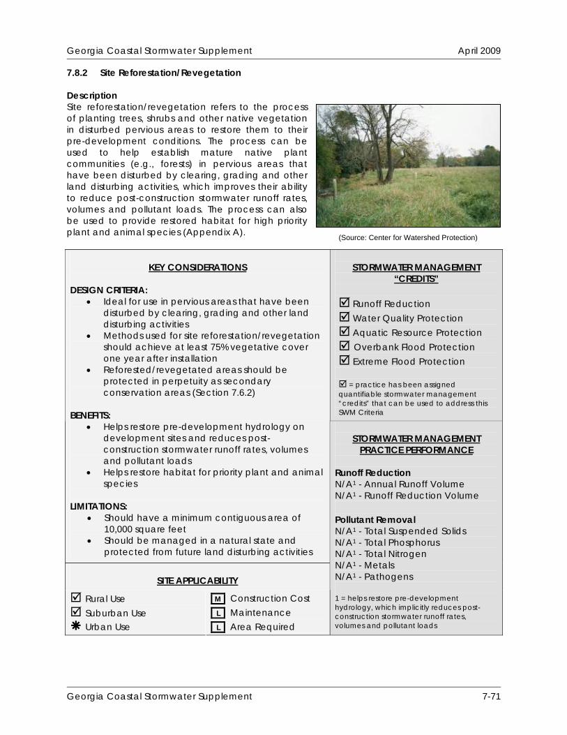
Georgia Coastal Stormwater Supplement April 2009
7.8.2 Site Reforestation/Revegetation Description Site reforestation/revegetation refers to the process of planting trees, shrubs and other native vegetation in disturbed pervious areas to restore them to their pre-development conditions. The process can be used to help establish mature native plant communities (e.g., forests) in pervious areas that have been disturbed by clearing, grading and other land disturbing activities, which improves their ability to reduce post-construction stormwater runoff rates, volumes and pollutant loads. The process can also be used to provide restored habitat for high priority plant and animal species (Appendix A).
STORMWATER MANAGEMENT
“CREDITS”
Runoff Reduction Water Quality Protection Aquatic Resource Protection Overbank Flood Protection Extreme Flood Protection = practice has been assigned quantifiable stormwater management “credits” that can be used to address this SWM Criteria
KEY CONSIDERATIONS
DESIGN CRITERIA:
Ideal for use in pervious areas that have been disturbed by clearing, grading and other land disturbing activities
Methods used for site reforestation/revegetation should achieve at least 75% vegetative cover one year after installation
Reforested/revegetated areas should be protected in perpetuity as secondary conservation areas (Section 7.6.2)
BENEFITS:
Helps restore pre-development hydrology on development sites and reduces post-construction stormwater runoff rates, volumes and pollutant loads
Helps restore habitat for priority plant and animal species
LIMITATIONS:
Should have a minimum contiguous area of 10,000 square feet
Should be managed in a natural state and protected from future land disturbing activities
SITE APPLICABILITY
Rural Use Suburban Use Urban Use
M Construction Cost L Maintenance L Area Required
STORMWATER MANAGEMENT
PRACTICE PERFORMANCE Runoff Reduction N/A1 - Annual Runoff Volume N/A1 - Runoff Reduction Volume Pollutant Removal N/A1 - Total Suspended Solids N/A1 - Total Phosphorus N/A1 - Total Nitrogen N/A1 - Metals N/A1 - Pathogens 1 = helps restore pre-development hydrology, which implicitly reduces post-construction stormwater runoff rates, volumes and pollutant loads
(Source: Center for Watershed Protection)
Georgia Coastal Stormwater Supplement 7-71

Georgia Coastal Stormwater Supplement April 2009
Discussion Site reforestation/revegetation refers to the process of planting trees, shrubs and other native vegetation in disturbed pervious areas to restore them to their pre-development conditions (Figure 7.24). The process can be used to help establish mature native plant communities (e.g., forests) in pervious areas that have been disturbed by clearing, grading and other land disturbing activities. Mature plant communities intercept rainfall, increase evaporation and transpiration rates, slow and filter stormwater runoff and help improve soil porosity and infiltration rates (Cappiella et al., 2006a), which leads to reduced post-construction stormwater runoff rates, volumes and pollutant loads. The site reforestation/revegetation process can also be used to provide restored habitat for high priority plant and animal species (Appendix A). Areas that have been reforested or revegetated should be maintained in an undisturbed, natural state over time. These areas should be designated as secondary conservation areas (Section 7.6.2) and protected in perpetuity through a legally enforceable conservation instrument (e.g., conservation easement, deed restriction). If properly maintained over time, these areas can help improve aesthetics on development sites, provide passive recreational opportunities and create valuable habitat for high priority plant and animal species. To help create contiguous, interconnected green infrastructure corridors on development sites, site planning and design teams should strive to connect reforested or revegetated areas with one another and with other primary and secondary conservation areas through the use of nature trails, bike trails and other “greenway” areas. Stormwater Management “Credits” The Center for Watershed Protection (Hirschman et al., 2008) recently documented the ability of the site reforestation/revegetation process to reduce annual stormwater runoff volumes and pollutant loads on development sites. Consequently, this low impact development practice has been assigned quantifiable stormwater management “credits” that can be used to help satisfy the SWM Criteria presented in this CSS:
Stormwater Runoff Reduction: Subtract 50% of any reforested/revegetated areas from the total site area and re-calculate the runoff reduction volume (RRv) that applies to the development site.
Water Quality Protection: Subtract 50% of any reforested/revegetated areas from the
total site area and re-calculate the runoff reduction volume (RRv) that applies to the development site.
Aquatic Resource Protection: Assume that the post-development hydrologic conditions
of any reforested/revegetated areas are equivalent to those of a similar cover type (e.g., meadow, brush, woods) in fair condition.
Figure 7.24: Active Replanting of Native Trees in a Disturbed
Pervious Area (Source: Center for Watershed Protection)
Georgia Coastal Stormwater Supplement 7-72

Georgia Coastal Stormwater Supplement April 2009
Overbank Flood Protection: Assume that the post-development hydrologic conditions of any reforested/revegetated areas are equivalent to those of a similar cover type (e.g., meadow, brush, woods) in fair condition.
Extreme Flood Protection: Assume that the post-development hydrologic conditions of
any reforested/revegetated areas are equivalent to those of a similar cover type (e.g., meadow, brush, woods) in fair condition.
Reforested/revegetated areas can only be assumed to be in “fair” hydrologic condition due to the fact that it will take many years for them to mature and provide full stormwater management benefits. If site reforestation/revegetation can be combined with soil restoration (Section 7.8.1) on a development site, the following stormwater management “credits” can be used to help satisfy the SWM Criteria presented in this CSS:
Stormwater Runoff Reduction: Subtract 100% of any restored and reforested/ revegetated areas from the total site area and re-calculate the runoff reduction volume (RRv) that applies to the development site.
Water Quality Protection: Subtract 100% of any restored and reforested/revegetated
areas from the total site area and re-calculate the runoff reduction volume (RRv) that applies to the development site.
Aquatic Resource Protection: Assume that the post-development hydrologic conditions
of any restored and reforested/revegetated areas are equivalent to those of a similar cover type (e.g., meadow, brush, woods) in good condition.
Overbank Flood Protection: Assume that the post-development hydrologic conditions of
any restored and reforested/revegetated areas are equivalent to those of a similar cover type (e.g., meadow, brush, woods) in good condition.
Extreme Flood Protection: Assume that the post-development hydrologic conditions of
any restored and reforested/revegetated areas are equivalent to those of a similar cover type (e.g., meadow, brush, woods) in good condition.
In order to be eligible for these “credits,” it is recommended that reforested/revegetated areas satisfy the planning and design criteria outlined below. Overall Feasibility The criteria listed in Table 7.8 should be evaluated to determine whether or not site reforestation/revegetation is appropriate for use on a development site.
Table 7.8: Factors to Consider When Evaluating the Overall Feasibility of Using Site Reforestation/Revegetation on a Development Site
Site Characteristic Criteria Drainage Area N/A
Area Required Reforested/revegetated areas should be larger than 10,000 square feet in size in order to be eligible for the stormwater management “credits” assigned to this low impact development practice.
Slope Maximum 25% in the disturbed pervious area to be reforested/ revegetated.
Georgia Coastal Stormwater Supplement 7-73

Georgia Coastal Stormwater Supplement April 2009
Table 7.8: Factors to Consider When Evaluating the Overall Feasibility of Using Site Reforestation/Revegetation on a Development Site
Site Characteristic Criteria Minimum Head N/A Minimum Depth to Water Table No restrictions
Soils No restrictions Site Applicability Although it may be difficult to apply in urban areas, due to space constraints, site reforestation/ revegetation can be used on a wide variety of development sites, including residential, commercial, industrial and institutional development sites in rural and suburban areas. When compared with other low impact development practices, it has a moderate construction cost, a relatively low maintenance burden and requires no additional surface area beyond that which will undergo the reforestation/revegetation process. It is ideal for use in pervious areas that have been disturbed by clearing, grading and other land disturbing activities. Planning and Design Criteria It is recommended that the reforestation/revegetation process used on a development site meet all of the following criteria to be eligible for the stormwater management “credits” described above: General Planning and Design
Reforested/revegetated areas should have a contiguous area of 10,000 square feet or more.
Reforested/revegetated areas should not be disturbed after construction (except for disturbances associated with landscaping or removal of invasive vegetation).
Reforested/revegetated areas should be protected, in perpetuity, from the direct impacts of the land development process by a legally enforceable conservation instrument (e.g., conservation easement, deed restriction).
Landscaping
A landscaping plan should be prepared for all reforested/revegetated areas. The landscaping plan should be reviewed and approved by the local development review authority prior to construction.
Landscaping commonly used in site reforestation/revegetation efforts includes native trees, shrubs and other herbaceous vegetation. Because the goal of the site reforestation/revegetation process is to establish a mature native plant community (e.g., forest), managed turf cannot be used to landscape reforested/revegetated areas.
Methods used for site reforestation/revegetation should achieve at least 75 percent vegetative cover one year after installation.
A long-term vegetation management plan should be developed for all reforested/revegetated areas. The plan should clearly specify how the area will be maintained in an undisturbed, natural state over time. Turf management is not considered to be an acceptable form of vegetation management. Consequently, only reforested/revegetated areas that remain in an undisturbed, natural state are eligible for this “credit” (i.e., pervious areas consisting of managed turf are not eligible for this “credit”).
Georgia Coastal Stormwater Supplement 7-74
Georgia Coastal Stormwater Supplement April 2009
Construction Considerations To help ensure that the site reforestation/revegetation process is successfully completed on a development site, site planning and design teams should consider the following recommendations:
Document the condition of the reforested/revegetated area before, during and after the completion of the site reforestation/revegetation process.
To help prevent soil compaction, heavy vehicular and foot traffic should be kept out of all reforested/revegetated areas before, during and after construction. This can typically be accomplished by clearly delineating reforested/revegetated areas on all development plans and, if necessary, protecting them with temporary construction fencing.
Simple erosion and sediment control measures, such as temporary seeding and erosion control mats, should be used on reforested/revegetated areas that exceed 2,500 square feet in size. If the reforested/revegetated areas will “receive” any stormwater runoff from other portions of the development site, measures should be taken (e.g., silt fence, temporary diversion berm) to prevent it from compromising the reforestation/ revegetation effort.
Construction contracts should contain a replacement warranty that covers at least three growing seasons to help ensure adequate growth and survival of the vegetation planted on the reforested/revegetated area.
Maintenance Requirements Reforested/revegetated areas require some maintenance during the first few months following construction, but typically require very little maintenance after that. Table 7.9 provides a list of the routine maintenance activities typically associated with reforested/revegetated areas.
Table 7.9: Routine Maintenance Activities Typically Associated with Site Reforestation/Revegetation
Activity Schedule Water to promote plant growth and survival. Inspect reforested/revegetated area following rainfall
events. Plant replacement vegetation in any eroded areas.
As Needed (Following Construction)
Inspect reforested/revegetated area for erosion. Plant replacement vegetation in any eroded areas.
Inspect reforested/revegetated area for dead or dying vegetation. Plant replacement vegetation as needed.
Prune and care for individual trees and shrubs as needed.
Annually (Semi-Annually During First Year)
Additional Resources Cappiella, K., T. Schueler and T. Wright. 2006a. Urban Watershed Forestry Manual. Part 2:
Conserving and Planting Trees at Development Sites. NA-TP-01-06. US Department of Agriculture. Forest Service. Northeastern Area. State and Private Forestry. Newtown Square, PA. Available Online: http://www.cwp.org/Resource_Library/Special_Resource_Management/forestry.htm.
Georgia Coastal Stormwater Supplement 7-75

Georgia Coastal Stormwater Supplement April 2009
Cappiella, K., T. Schueler, J. Tomlinson and T. Wright. 2006b. Urban Watershed Forestry Manual. Part 3: Urban Tree Planting Guide. NA-TP-01-06. US Department of Agriculture. Forest Service. Northeastern Area. State and Private Forestry. Newtown Square, PA. Available Online: http://www.cwp.org/Resource_Library/Special_Resource_Management/forestry.htm.
Minnesota Pollution Control Agency (MPCA). 2006. “Credit 2: Site Reforestation or Prairie
Restoration Credit.” Minnesota Stormwater Manual. Section 11.3.2. Minnesota Pollution Control Agency. Available Online: http://www.pca.state.mn.us/water/stormwater/stormwater-manual.html.
Pennsylvania Department of Environmental Protection (PA DEP). 2006. “BMP 6.7.3: Soil
Amendment and Restoration.” Pennsylvania Stormwater Best Management Practices Manual. Section 6.7.3. Pennsylvania Department of Environmental Protection. Bureau of Watershed Management. Available Online: http://www.depweb.state.pa.us/watershedmgmt/site/default.asp.
Georgia Coastal Stormwater Supplement 7-76

Georgia Coastal Stormwater Supplement April 2009
7.8.3 Green Roofs Description Green roofs represent an alternative to traditional impervious roof surfaces. They typically consist of underlying waterproofing and drainage materials and an overlying engineered growing media that is designed to support plant growth. Stormwater runoff is captured and temporarily stored in the engineered growing media, where it is subjected to the hydrologic processes of evaporation and transpiration before being conveyed back into the storm drain system. This allows green roofs to provide measurable reductions in post-construction stormwater runoff rates, volumes and pollutant loads on development sites.
STORMWATER MANAGEMENT
“CREDITS”
Runoff Reduction Water Quality Protection Aquatic Resource Protection Overbank Flood Protection Extreme Flood Protection = practice has been assigned quantifiable stormwater management “credits” that can be used to address this SWM Criteria
KEY CONSIDERATIONS
DESIGN CRITERIA:
The use of extensive green roof systems (2”-6” deep) should be considered prior to the use of more complex and expensive intensive green roof systems
Engineered growing media should be a light-weight mix and should contain less than 10% organic material
Waterproofing materials should be protected from root penetration by an impermeable root barrier
BENEFITS:
Helps reduce post-construction stormwater runoff rates, volumes and pollutant loads without consuming valuable land
Particularly well suited for use on urban development and redevelopment sites
LIMITATIONS:
Can be difficult to establish vegetation in the harsh growing conditions found on rooftops in coastal Georgia
Green roofs can be difficult to install on rooftops with slopes of 10% or greater
SITE APPLICABILITY
Rural Use Suburban Use Urban Use
H Construction Cost M Maintenance L Area Required
STORMWATER MANAGEMENT
PRACTICE PERFORMANCE Runoff Reduction 50% - Annual Runoff Volume 60% - Runoff Reduction Volume Pollutant Removal1 80% - Total Suspended Solids 50% - Total Phosphorus 50% - Total Nitrogen N/A - Metals N/A - Pathogens 1 = expected annual pollutant load removal
(Source: http://www.greenroofs.com)
Georgia Coastal Stormwater Supplement 7-77

Georgia Coastal Stormwater Supplement April 2009
Discussion Green roofs (also known as vegetated roofs or eco roofs) represent an alternative to traditional impervious roof surfaces. They typically consist of underlying waterproofing and drainage materials and an overlying engineered growing media that is designed to support plant growth (Figure 7.25). Stormwater runoff is captured and temporarily stored in the engineered growing media, where it is subjected to the hydrologic processes of evaporation and transpiration, before being conveyed back into the storm drain system. This allows green roofs to provide measurable reductions in post-construction stormwater runoff rates, volumes and pollutant loads on development sites. There are two different types of green roof systems: intensive green roof systems and extensive green roof systems. Intensive green roof systems (also known as rooftop gardens) have a thick layer of engineered growing media (i.e., 12 to 24 inches) that supports a diverse plant community that may even include trees (Figure 7.26). Extensive green roof systems typically have a much thinner layer of engineered growing media (i.e., 2 to 6 inches) that supports a plant community that is comprised primarily of drought tolerant vegetation (e.g., sedums, succulent plants) (Figure 7.27). Extensive green roof systems, which can cost up to twice as much as traditional impervious roof surfaces, are much lighter and are less expensive than intensive green roof systems. Consequently, it is recommended that the use of extensive green roof systems be considered prior to the use of intensive green roof systems in coastal Georgia.
Figure 7.25: Components of a Green Roof System (Source: Carter et al., 2007)
Figure 7.26: Intensive Green Roof System (Source: City of Portland, OR, 2004)
Georgia Coastal Stormwater Supplement 7-78
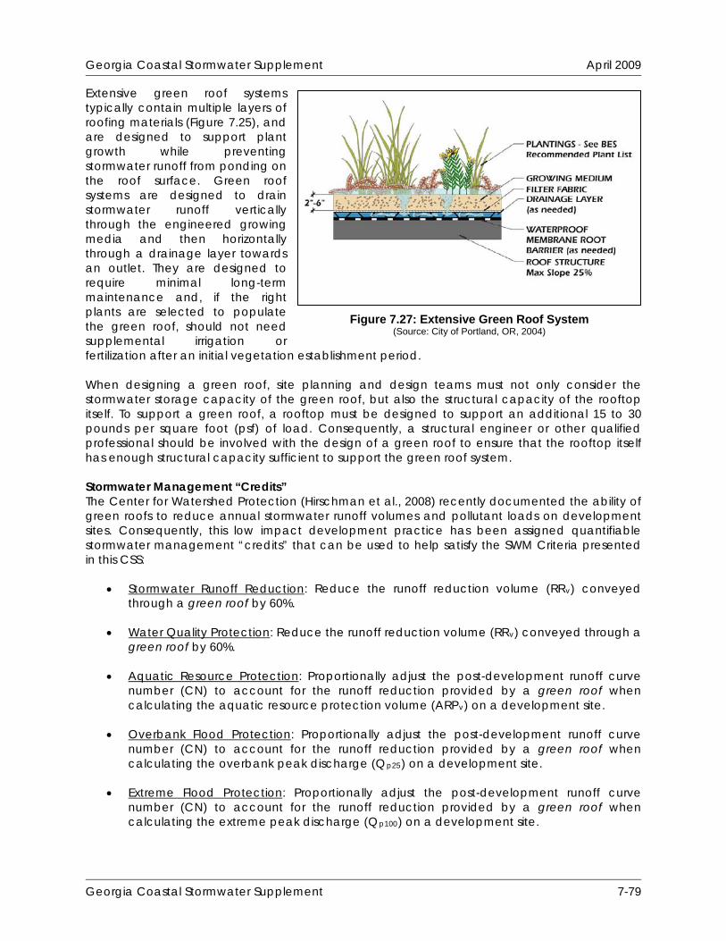
Georgia Coastal Stormwater Supplement April 2009
Extensive green roof systems typically contain multiple layers of roofing materials (Figure 7.25), and are designed to support plant growth while preventing stormwater runoff from ponding on the roof surface. Green roof systems are designed to drain stormwater runoff vertically through the engineered growing media and then horizontally through a drainage layer towards an outlet. They are designed to require minimal long-term maintenance and, if the right plants are selected to populate the green roof, should not need supplemental irrigation or fertilization after an initial vegetation establishment period. When designing a green roof, site planning and design teams must not only consider the stormwater storage capacity of the green roof, but also the structural capacity of the rooftop itself. To support a green roof, a rooftop must be designed to support an additional 15 to 30 pounds per square foot (psf) of load. Consequently, a structural engineer or other qualified professional should be involved with the design of a green roof to ensure that the rooftop itself has enough structural capacity sufficient to support the green roof system. Stormwater Management “Credits” The Center for Watershed Protection (Hirschman et al., 2008) recently documented the ability of green roofs to reduce annual stormwater runoff volumes and pollutant loads on development sites. Consequently, this low impact development practice has been assigned quantifiable stormwater management “credits” that can be used to help satisfy the SWM Criteria presented in this CSS:
Stormwater Runoff Reduction: Reduce the runoff reduction volume (RRv) conveyed through a green roof by 60%.
Water Quality Protection: Reduce the runoff reduction volume (RRv) conveyed through a
green roof by 60%.
Aquatic Resource Protection: Proportionally adjust the post-development runoff curve number (CN) to account for the runoff reduction provided by a green roof when calculating the aquatic resource protection volume (ARPv) on a development site.
Overbank Flood Protection: Proportionally adjust the post-development runoff curve
number (CN) to account for the runoff reduction provided by a green roof when calculating the overbank peak discharge (Qp25) on a development site.
Extreme Flood Protection: Proportionally adjust the post-development runoff curve
number (CN) to account for the runoff reduction provided by a green roof when calculating the extreme peak discharge (Qp100) on a development site.
Figure 7.27: Extensive Green Roof System (Source: City of Portland, OR, 2004)
Georgia Coastal Stormwater Supplement 7-79
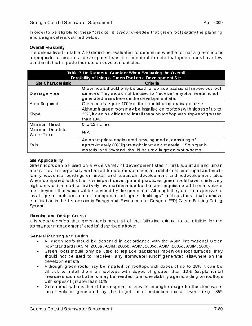
Georgia Coastal Stormwater Supplement April 2009
In order to be eligible for these “credits,” it is recommended that green roofs satisfy the planning and design criteria outlined below. Overall Feasibility The criteria listed in Table 7.10 should be evaluated to determine whether or not a green roof is appropriate for use on a development site. It is important to note that green roofs have few constraints that impede their use on development sites.
Table 7.10: Factors to Consider When Evaluating the Overall Feasibility of Using a Green Roof on a Development Site
Site Characteristic Criteria
Drainage Area Green roofs should only be used to replace traditional impervious roof surfaces. They should not be used to “receive” any stormwater runoff generated elsewhere on the development site.
Area Required Green roofs require 100% of their contributing drainage areas.
Slope Although green roofs may be installed on rooftops with slopes of up to 25%, it can be difficult to install them on rooftop with slopes of greater than 10%.
Minimum Head 6 to 12 inches Minimum Depth to Water Table N/A
Soils An appropriate engineered growing media, consisting of approximately 80% lightweight inorganic material, 15% organic material and 5% sand, should be used in green roof systems.
Site Applicability Green roofs can be used on a wide variety of development sites in rural, suburban and urban areas. They are especially well suited for use on commercial, institutional, municipal and multi-family residential buildings on urban and suburban development and redevelopment sites. When compared with other low impact development practices, green roofs have a relatively high construction cost, a relatively low maintenance burden and require no additional surface area beyond that which will be covered by the green roof. Although they can be expensive to install, green roofs are often a component of “green buildings,” such as those that achieve certification in the Leadership in Energy and Environmental Design (LEED) Green Building Rating System. Planning and Design Criteria It is recommended that green roofs meet all of the following criteria to be eligible for the stormwater management “credits” described above: General Planning and Design
All green roofs should be designed in accordance with the ASTM International Green Roof Standards (ASTM, 2005a, ASTM, 2005b, ASTM, 2005c, ASTM, 2005d, ASTM, 2006).
Green roofs should only be used to replace traditional impervious roof surfaces. They should not be used to “receive” any stormwater runoff generated elsewhere on the development site.
Although green roofs may be installed on rooftops with slopes of up to 25%, it can be difficult to install them on rooftops with slopes of greater than 10%. Supplemental measures, such as battens, may be needed to ensure stability against sliding on rooftops with slopes of greater than 10%.
Green roof systems should be designed to provide enough storage for the stormwater runoff volume generated by the target runoff reduction rainfall event (e.g., 85th
Georgia Coastal Stormwater Supplement 7-80
Georgia Coastal Stormwater Supplement April 2009
percentile rainfall event). The required dimensions of a green roof system are governed by several factors, including the hydraulic conductivity and moisture retention capacity of the engineered growing media and the porosity of the underlying drainage layer. Site planning and design teams are encouraged to consult with green roof manufacturers and/or materials suppliers to design green roof systems that provide enough storage for the stormwater runoff volume generated by the target runoff reduction rainfall event (e.g., 85th percentile rainfall event).
During the design of a green roof system, site planning and design teams should consider not only the storage capacity of the green roof, but also the structural capacity of the rooftop itself. A structural engineer or other qualified professional should be involved with the design of a green roof to ensure that the rooftop itself has enough structural capacity to support the green roof system.
All green roof systems should include a waterproofing layer that will prevent stormwater runoff from damaging the underlying rooftop. Waterproofing materials typically used in green roof installations include reinforced thermoplastic and synthetic rubber membranes.
The waterproofing layer should be protected from root penetration by an impermeable, physical root barrier. Chemical root barriers or physical root barriers that have been impregnated with pesticides, metals or other chemicals that may leach into post-construction stormwater runoff should not be used.
A drainage layer should be placed between the root barrier and the engineered growing media. The drainage layer should consist of synthetic or inorganic materials (e.g., gravel, recycled polyethylene) that are capable of both retaining water and providing efficient drainage when the layer becomes saturated. The required depth of the drainage layer will be governed by the required storage capacity of the green roof system and by the structural capacity of the rooftop itself.
An outlet (e.g., scupper and downspout) should be provided to convey stormwater runoff out of the drainage layer and off of the rooftop when the drainage layer becomes saturated.
An appropriate engineered growing media, consisting of approximately 80% lightweight inorganic materials, 15% organic matter (e.g., well-aged compost) and 5% sand, should be installed above the drainage layer. The engineered growing media should have a maximum water retention capacity of approximately 30%.
To prevent clogging within the drainage layer, the engineered growing media should be separated from the drainage layer by a layer of permeable filter fabric. The filter fabric should be a non-woven geotextile with a permeability that is greater than or equal to the hydraulic conductivity of the overlying engineered growing media.
The engineered growing media should be between 4 and 6 inches deep, unless synthetic moisture retention materials (e.g., drainage mat with moisture storage “cups”) are placed directly beneath the engineered growing media layer. When synthetic moisture retention materials are used, a 2 inch deep engineered growing media layer may be used.
Consideration should be given to the stormwater runoff rates and volumes generated by larger storm events (e.g., 25-year, 24-hour storm event) to help ensure that these larger storm events are able to safely bypass the green roof system. An overflow system, such as a traditional rooftop drainage system with inlets set slightly above the elevation of the surface of the green roof, should be designed to convey the stormwater runoff generated by these larger storm events safely off of the rooftop.
Georgia Coastal Stormwater Supplement 7-81
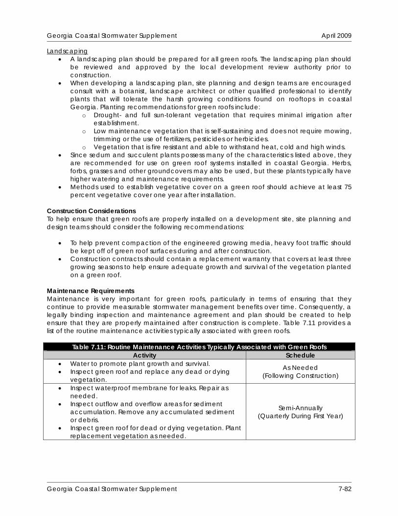
Georgia Coastal Stormwater Supplement April 2009
Landscaping A landscaping plan should be prepared for all green roofs. The landscaping plan should
be reviewed and approved by the local development review authority prior to construction.
When developing a landscaping plan, site planning and design teams are encouraged consult with a botanist, landscape architect or other qualified professional to identify plants that will tolerate the harsh growing conditions found on rooftops in coastal Georgia. Planting recommendations for green roofs include:
o Drought- and full sun-tolerant vegetation that requires minimal irrigation after establishment.
o Low maintenance vegetation that is self-sustaining and does not require mowing, trimming or the use of fertilizers, pesticides or herbicides.
o Vegetation that is fire resistant and able to withstand heat, cold and high winds. Since sedum and succulent plants possess many of the characteristics listed above, they
are recommended for use on green roof systems installed in coastal Georgia. Herbs, forbs, grasses and other groundcovers may also be used, but these plants typically have higher watering and maintenance requirements.
Methods used to establish vegetative cover on a green roof should achieve at least 75 percent vegetative cover one year after installation.
Construction Considerations To help ensure that green roofs are properly installed on a development site, site planning and design teams should consider the following recommendations:
To help prevent compaction of the engineered growing media, heavy foot traffic should be kept off of green roof surfaces during and after construction.
Construction contracts should contain a replacement warranty that covers at least three growing seasons to help ensure adequate growth and survival of the vegetation planted on a green roof.
Maintenance Requirements Maintenance is very important for green roofs, particularly in terms of ensuring that they continue to provide measurable stormwater management benefits over time. Consequently, a legally binding inspection and maintenance agreement and plan should be created to help ensure that they are properly maintained after construction is complete. Table 7.11 provides a list of the routine maintenance activities typically associated with green roofs.
Table 7.11: Routine Maintenance Activities Typically Associated with Green Roofs Activity Schedule
Water to promote plant growth and survival. Inspect green roof and replace any dead or dying
vegetation.
As Needed (Following Construction)
Inspect waterproof membrane for leaks. Repair as needed.
Inspect outflow and overflow areas for sediment accumulation. Remove any accumulated sediment or debris.
Inspect green roof for dead or dying vegetation. Plant replacement vegetation as needed.
Semi-Annually (Quarterly During First Year)
Georgia Coastal Stormwater Supplement 7-82

Georgia Coastal Stormwater Supplement April 2009
Additional Resources ASTM International. 2005. Standard Practice for Determination of Dead Loads and Live Loads
Associated with Green Roof Systems. Standard E2397-05. ASTM International. West Conshohocken, PA. Available Online: http://www.astm.org/Standards/E2397.htm.
ASTM International. 2006. Standard Guide for Selection, Installation and Maintenance of Plants
for Green Roof Systems. Standard E2400-06. ASTM International. West Conshohocken, PA. Available Online: http://www.astm.org/Standards/E2400.htm.
City of Portland, OR. 2008. “Ecoroof.” Portland Stormwater Management Manual. Section 2.3.3.
City of Portland, OR. Bureau of Environmental Services. Available Online: http://www.portlandonline.com/bes/index.cfm?c=47952.
Pennsylvania Department of Environmental Protection (PA DEP). 2006. “BMP 6.5.1: Vegetated
Roof.” Pennsylvania Stormwater Best Management Practices Manual. Section 6.5.1. Pennsylvania Department of Environmental Protection. Bureau of Watershed Management. Available Online: http://www.depweb.state.pa.us/watershedmgmt/site/default.asp.
Georgia Coastal Stormwater Supplement 7-83

Georgia Coastal Stormwater Supplement April 2009
THIS PAGE INTENTIONALLY LEFT BLANK
Georgia Coastal Stormwater Supplement 7-84
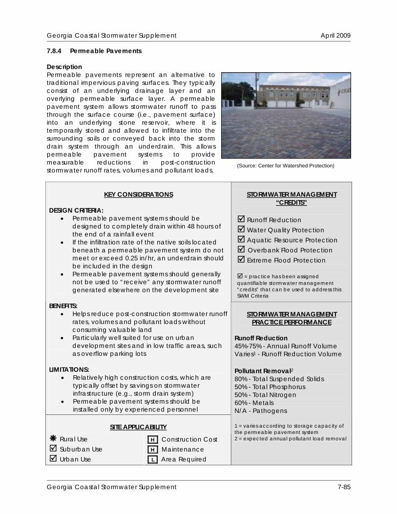
Georgia Coastal Stormwater Supplement April 2009
7.8.4 Permeable Pavements Description Permeable pavements represent an alternative to traditional impervious paving surfaces. They typically consist of an underlying drainage layer and an overlying permeable surface layer. A permeable pavement system allows stormwater runoff to pass through the surface course (i.e., pavement surface) into an underlying stone reservoir, where it is temporarily stored and allowed to infiltrate into the surrounding soils or conveyed back into the storm drain system through an underdrain. This allows permeable pavement systems to provide measurable reductions in post-construction stormwater runoff rates, volumes and pollutant loads.
STORMWATER MANAGEMENT
“CREDITS”
Runoff Reduction Water Quality Protection Aquatic Resource Protection Overbank Flood Protection Extreme Flood Protection = practice has been assigned quantifiable stormwater management “credits” that can be used to address this SWM Criteria
KEY CONSIDERATIONS
DESIGN CRITERIA:
Permeable pavement systems should be designed to completely drain within 48 hours of the end of a rainfall event
If the infiltration rate of the native soils located beneath a permeable pavement system do not meet or exceed 0.25 in/hr, an underdrain should be included in the design
Permeable pavement systems should generally not be used to “receive” any stormwater runoff generated elsewhere on the development site
BENEFITS:
Helps reduce post-construction stormwater runoff rates, volumes and pollutant loads without consuming valuable land
Particularly well suited for use on urban development sites and in low traffic areas, such as overflow parking lots
LIMITATIONS:
Relatively high construction costs, which are typically offset by savings on stormwater infrastructure (e.g., storm drain system)
Permeable pavement systems should be installed only by experienced personnel
SITE APPLICABILITY
Rural Use Suburban Use Urban Use
H Construction Cost H Maintenance L Area Required
STORMWATER MANAGEMENT
PRACTICE PERFORMANCE Runoff Reduction 45%-75% - Annual Runoff Volume Varies1 - Runoff Reduction Volume Pollutant Removal2 80% - Total Suspended Solids 50% - Total Phosphorus 50% - Total Nitrogen 60% - Metals N/A - Pathogens 1 = varies according to storage capacity of the permeable pavement system 2 = expected annual pollutant load removal
(Source: Center for Watershed Protection)
Georgia Coastal Stormwater Supplement 7-85

Georgia Coastal Stormwater Supplement April 2009
Discussion Permeable pavements represent an alternative to traditional impervious paving surfaces. They typically consist of an underlying drainage layer and an overlying permeable surface layer. A permeable pavement system allows stormwater runoff to pass through the surface course (i.e., pavement surface) into an underlying stone reservoir, where it is temporarily stored and allowed to infiltrate into the surrounding soils or conveyed back into the storm drain system through an underdrain (Figure 7.28). This allows permeable pavement systems to provide measurable reductions in post-construction stormwater runoff rates, volumes and pollutant loads on development sites. There are a variety of permeable pavement surfaces available in the commercial marketplace, including pervious concrete, porous asphalt, permeable interlocking concrete pavers, concrete grid pavers and plastic grid pavers (Figure 7.29). Each of these permeable pavement surfaces is briefly described below:
Pervious Concrete: Pervious concrete (also known as porous concrete) is similar to conventional concrete in structure and form, but consists of a special open-graded surface course, typically 4 to 8 inches thick, that is bound together with portland cement. This open-graded surface course has a void ratio of 15% to 25% (conventional concrete pavement has a void ratio of between 3% and 5%), which gives it a high permeability that is often many times more than that of the underlying native soils, and allows rainwater and stormwater runoff to rapidly pass through it and into the underlying stone reservoir. Although this particular type permeable pavement surface may not require an underlying base layer to support traffic loads, site planning and design teams may wish to provide it to increase the stormwater storage capacity provided by a pervious concrete system.
Porous Asphalt: Porous asphalt is similar to pervious concrete, and consists of a special
open-graded surface course bound together by asphalt cement. The open-graded surface course in a typical porous asphalt installation is 3 to 7 inches thick and has a void ratio of between 15% and 20%. Porous asphalt is thought to have a limited ability to maintain its structure and permeability during hot summer months and, consequently, is currently not recommended for use in coastal Georgia. If it is used on a development site in the 24-county coastal region, it should be carefully monitored and maintained over time.
Permeable Interlocking Concrete Pavers: Permeable interlocking concrete pavers (PICP)
are solid structural units (e.g., blocks, bricks) that are installed in a way that provides regularly spaced openings through which stormwater runoff can rapidly pass through the pavement surface and into the underlying stone reservoir. The regularly spaced
Figure 7.28: Components of a Permeable Pavement System
(Source: Hunt and Collins, 2008)
Georgia Coastal Stormwater Supplement 7-86

Georgia Coastal Stormwater Supplement April 2009
(Source: Atlanta Regional Commission, 2001) (Source: Center for Watershed Protection)
Concrete Grid Pavers Pervious Concrete
(Source: Center for Watershed Protection)
Permeable Interlocking Concrete Pavers
(Source: Atlanta Regional Commission, 2001)
Plastic Grid Pavers
Figure 7.29: Various Permeable Pavement Surfaces
openings, which generally make up between 8% and 20% of the total pavement surface, are typically filled with pea gravel (i.e., ASTM D 448 Size No. 8, 3/8” to 1/8”). Typical PICP systems consist of the pavers, a 1.5 to 3 inch thick fine gravel bedding layer and an underlying stone reservoir (Figure 7.28).
Concrete Grid Pavers: Concrete grid pavers (CGP) are precast concrete units that allow
rainfall and stormwater runoff to pass through large openings that are filled with gravel, sand or topsoil and turf (Figure 7.29). CGP are typically 3.5 inches thick and have between a void ratio of between 20% and 50%, which means that the material used to fill the spaces between the grids has a large influence on the overall permeability (i.e., void space) of a CGP system. A typical CGP installation consists of the pavers, a 1 to 1.5 inch sand or pea gravel bedding layer and an underlying stone reservoir.
Plastic Grid Pavers: Plastic grid pavers (PGP) are similar to CGP. They consist of flexible,
interlocking plastic units that allow rainfall and stormwater runoff to pass through large openings that are filled with gravel, sand or topsoil and turf (Figure 7.29). Since the empty plastic grids have a void ratio of between 90% and 98%, the material used to fill the
Georgia Coastal Stormwater Supplement 7-87

Georgia Coastal Stormwater Supplement April 2009
spaces between the grids has a large influence on the overall permeability (i.e., void space) a PGP system.
When designing a permeable pavement system, planning and design teams must not only consider the storage capacity of the system, but also the structural capacity of the underlying soils and the underlying stone reservoir. The infiltration rate and structural capacity of the native soils found on a development site directly influence the size of the stone reservoir that is needed to provide structural support for a permeable pavement system and measurable reductions in post-construction stormwater runoff rates, volumes and pollutant loads. Site planning and design teams should strive to design permeable pavement systems that can accommodate the stormwater runoff volume generated by the target runoff reduction rainfall event (e.g., 85th percentile rainfall event). If this cannot be accomplished, due to site characteristics or constraints, site planning and design teams should consider using permeable pavement systems in combination with other runoff reducing low impact development practices. Although permeable pavement systems have seen some use in coastal Georgia, there is still limited experience with the design and installation of this low impact development within the region. On the national scale, permeable pavement installations have had high failure rates due to poor design, poor installation, underlying soils with low infiltration rates and poor maintenance practices (ARC, 2001). Consequently, if a permeable pavement system is used on a development site, it should be carefully monitored and maintained over time. Stormwater Management “Credits” The Center for Watershed Protection (Hirschman et al., 2008) recently documented the ability of permeable pavement systems to reduce annual stormwater runoff volumes and pollutant loads on development sites. Consequently, this low impact development practice has been assigned quantifiable stormwater management “credits” that can be used to help satisfy the SWM Criteria presented in this CSS:
Stormwater Runoff Reduction: Subtract 100% of the storage volume provided by a non-underdrained permeable pavement system from the runoff reduction volume (RRv) conveyed through the system. Subtract 50% of the storage volume provided by an underdrained permeable pavement system from the runoff reduction volume (RRv) conveyed through the system.
Water Quality Protection: Subtract 100% of the storage volume provided by a non-
underdrained permeable pavement system from the runoff reduction volume (RRv) conveyed through the system. Subtract 50% of the storage volume provided by an underdrained permeable pavement system from the runoff reduction volume (RRv) conveyed through the system.
Aquatic Resource Protection: Proportionally adjust the post-development runoff curve
number (CN) to account for the runoff reduction provided by a permeable pavement system when calculating the aquatic resource protection volume (ARPv) on a development site.
Overbank Flood Protection: Proportionally adjust the post-development runoff curve
number (CN) to account for the runoff reduction provided by a permeable pavement system when calculating the overbank peak discharge (Qp25) on a development site.
Georgia Coastal Stormwater Supplement 7-88
Georgia Coastal Stormwater Supplement April 2009
Extreme Flood Protection: Proportionally adjust the post-development runoff curve number (CN) to account for the runoff reduction provided by a permeable pavement system when calculating the extreme peak discharge (Qp100) on a development site.
The storage volume provided by a permeable pavement system can be determined using the following equation:
Storage Volume = Surface Area x Depth x Void Ratio A void ratio (i.e., void space/total volume) of 0.32 should be used in all storage volume calculations, unless more specific aggregate void ratio data are available. In order to be eligible for these “credits,” it is recommended that permeable pavement systems satisfy the planning and design criteria outlined below. Overall Feasibility The criteria listed in Table 7.12 should be evaluated to determine whether or not a permeable pavement system is appropriate for use on a development site.
Table 7.12: Factors to Consider When Evaluating the Overall Feasibility of Using a Permeable Pavement System on a Development Site
Site Characteristic Criteria
Drainage Area
Permeable pavement systems should only be used to replace traditional impervious paving surfaces. They should not be used to “receive” any stormwater runoff generated elsewhere on the development site.
Area Required Permeable pavement systems require 100% of their contributing drainage areas.
Slope
Although permeable pavement systems may be installed on development sites with slopes of up to 6%, they should be designed with slopes that are as close to flat as possible to help ensure that stormwater runoff is evenly distributed throughout the stone reservoir.
Minimum Head 2 to 4 feet Minimum Depth to Water Table 2 feet
Soils
Permeable pavement systems should be designed to completely drain within 48 hours of the end of a rainfall event. Consequently, non-underdrained permeable pavement systems generally should not be used on development sites that have soils with infiltration rates of less than 0.25 inches per hour (i.e., hydrologic soil group C and D soils).
Feasibility in Coastal Georgia Several site characteristics commonly encountered in coastal Georgia may present challenges to site planning and design teams that are interested in using permeable pavement on a development site. Table 7.13 identifies these common site characteristics and describes how they influence the use of permeable pavement systems on development sites. The table also provides site planning and design teams with some ideas about how they can work around these potential constraints.
Georgia Coastal Stormwater Supplement 7-89

Georgia Coastal Stormwater Supplement April 2009
Table 7.13: Challenges Associated with Using Permeable Pavement Systems in Coastal Georgia
Site Characteristic How it Influences the Use of Permeable Pavement Potential Solutions
Poorly drained soils, such as hydrologic soil group C and D soils
Reduces the ability of permeable pavement systems to reduce stormwater runoff rates, volumes and pollutant loads.
An underdrain should be included in permeable pavement systems that will be installed development sites that have soils with infiltration rates of less than 0.25 inches per hour (i.e., hydrologic soil group C and D soils).
Use additional low impact development practices to supplement the stormwater management benefits provided by underdrained permeable pavement systems.
Well drained soils, such as hydrologic soil group A and B soils
Enhances the ability of permeable pavement systems to reduce stormwater runoff rates, volumes and pollutant loads, but may allow stormwater pollutants to reach groundwater aquifers with greater ease.
Avoid the use of infiltration-based low impact development practices, including non-underdrained permeable pavement systems, at stormwater hotspots and in areas known to provide groundwater recharge to water supply aquifers.
Use permeable pavement systems with liners and underdrains at stormwater hotspots and in areas known to provide groundwater recharge to water supply aquifers.
Flat terrain Does not influence the use of permeable pavement systems. In fact, permeable pavement systems should be designed with slopes that are as close to flat as possible.
Shallow water table
May cause stormwater runoff pond at the bottom of the permeable pavement system.
Ensure that the distance from the bottom of the permeable pavement system to the top of the water table is at least 2 feet.
Use stormwater ponds (Section 8.6.1) and stormwater wetlands (Section 8.6.2) to intercept and treat stormwater runoff in these areas.
Georgia Coastal Stormwater Supplement 7-90

Georgia Coastal Stormwater Supplement April 2009
Table 7.13: Challenges Associated with Using Permeable Pavement Systems in Coastal Georgia
How it Influences the Use Site Characteristic Potential Solutions of Permeable Pavement Tidally-influenced
drainage system May occasionally prevent
stormwater runoff from being conveyed through a permeable pavement system, particularly during high tide.
Investigate the use of other low impact development practices, such as rainwater harvesting (Section 7.8.12) to “receive” stormwater runoff in these areas.
Site Applicability Permeable pavement systems can be used on a wide range of development sites in rural, suburban and urban areas. They are especially well suited for use on urban development and redevelopment sites to construct sidewalks, parking lots, overflow parking areas, private streets and driveways and parking lanes on public streets and roadways. When compared with other low impact development practices, permeable pavement systems have a relatively high construction cost, a relatively high maintenance burden and require no additional surface area beyond that which will be covered by the permeable pavement system. Planning and Design Criteria It is recommended that permeable pavement systems meet all of the following criteria to be eligible for the stormwater management “credits” described above: General Planning and Design
Permeable pavement systems should only be used to replace traditional impervious paving surfaces. They should not be used to “receive” any stormwater runoff generated elsewhere on the development site.
Although permeable pavement systems may be installed on development sites with slopes of up to 6%, they should be designed with slopes that are as close to flat as possible to help ensure that stormwater runoff is evenly distributed throughout the stone reservoir.
Permeable pavement systems can be designed without an underdrain on development sites that have underlying soils with an infiltration rate of 0.25 inches per hour (in/hr) or greater, as determined by NRCS soil survey data and subsequent field testing. Field infiltration test protocol, such as that provided by the City of Portland, OR (Portland, OR, 2008) on the following website: http://www.portlandonline.com/shared/cfm/image.cfm?id= 202911, can be used to conduct field testing, but should be approved by the local development review authority prior to use.
Although the number of infiltration tests needed on a development site will ultimately be determined by the local development review authority, at least one infiltration test is recommended for every 5,000 square feet of permeable pavement that will be used on the development site. If the infiltration rate of the underlying soils on the development site is not 0.25 inches per hour (in/hr) or greater, an underdrain should be included in the permeable pavement system design.
Since clay lenses or any other restrictive layers located below the bottom of a permeable pavement system will reduce soil infiltration rates, infiltration testing should be conducted within any confining layers that are found within 4 feet of the bottom of a proposed permeable pavement system.
Permeable pavement systems should be designed to provide enough storage for the stormwater runoff volume generated by the target runoff reduction rainfall event (e.g.,
Georgia Coastal Stormwater Supplement 7-91

Georgia Coastal Stormwater Supplement April 2009
85th percentile rainfall event). Since they are essentially infiltration practices, the required dimensions of a non-underdrained permeable pavement system can be determined using the design procedures provided in Section 8.6.5 of this CSS. The required dimensions of an underdrained permeable pavement system can be determined by using the conveyance capacity of the selected underdrain system.
Permeable pavement systems should be designed to completely drain within 48 hours of the end of a rainfall event. Where site characteristics allow, it is preferable to design permeable pavement systems to drain within 24 hours of the end of a rainfall event to help prevent the formation of nuisance ponding conditions.
An appropriate permeable pavement surface should be selected for the intended application. The permeable pavement surface should be able to support the maximum projected traffic load.
Most permeable pavement surfaces need to be supported by an underlying stone reservoir (also known as a gravel base or aggregate base). The depth of the stone reservoir typically ranges between 1 and 4 feet, but should be determined by considering both the required stormwater storage capacity and the maximum projected traffic load that will be experienced by the permeable pavement system. On most development sites, the maximum projected traffic load will determine the depth of the underlying stone reservoir.
The stone reservoir should be filled with clean, washed stone. The stone used in the stone reservoir should be 1.5 to 2.5 inches in diameter, with a void space of approximately 40% (e.g., GA DOT No. 3 Stone). Unwashed aggregate contaminated with soil or other fines may not be used in the stone reservoir.
If no underdrain is required, underlying native soils should be separated from the stone reservoir by a thin, 2 to 4 inch layer of choker stone (i.e., ASTM D 448 size No. 8, 3/8” to 1/8” or ASTM D 448 size No. 89, 3/8” to 1/16”). The choker stone should be placed between the stone reservoir and the underlying native soils.
If an underdrain is required, it should be placed beneath the stone reservoir. The underdrain should consist of a 4 to 6 inch perforated PVC (AASHTO M 252) pipe bedded in an 8 inch layer of clean, washed stone. The pipe should have 3/8 inch perforations, spaced 6 inches on center, and should have a minimum slope of 0.5%. The clean, washed stone should be ASTM D448 size No. 57 stone (i.e., 1-1/2 to 1/2 inches in size) and should be separated from the stone reservoir by a thin, 2 to 4 inch layer of choker stone (i.e., ASTM D 448 size No. 8, 3/8” to 1/8” or ASTM D 448 size No. 89, 3/8” to 1/16”).
The sides of the stone reservoir should be lined with a layer of appropriate permeable filter fabric. The filter fabric should be a non-woven geotextile with a permeability that is greater than or equal to the infiltration rate of the surrounding native soils.
The depth from the bottom of a permeable pavement system to the top of the water table should be at least 2 feet to prevent nuisance ponding and ensure proper operation of the permeable pavement system.
To prevent damage to building foundations and contamination of groundwater aquifers permeable pavement systems, unless equipped with a waterproof liner (e.g., 30 mil (0.030 inch) polyvinylchloride (PVC) or equivalent), should be located at least:
o 10 feet from building foundations o 10 feet from property lines o 100 feet from private water supply wells o 1,200 feet from public water supply wells o 100 feet from septic systems o 100 feet from surface waters o 400 feet from public water supply surface waters
Consideration should be given to the stormwater runoff rates and volumes generated by larger storm events (e.g., 25-year, 24-hour storm event) to help ensure that these larger
Georgia Coastal Stormwater Supplement 7-92
Georgia Coastal Stormwater Supplement April 2009
storm events are able to safely bypass the permeable pavement system. An overflow system should be designed to convey the stormwater runoff generated by these larger storm events safely off of the pavement surface. Methods that can be used to accommodate the stormwater runoff rates and volumes generated by these larger storm events include:
o Allowing excess stormwater runoff to be safely conveyed off of the permeable pavement surface via sheet flow.
o Using storm drain inlets set slightly above the elevation of the permeable pavement surface to collect excess stormwater runoff. This will create some ponding on the surface of the permeable pavement system, but can be used to safely convey excess stormwater runoff off of the permeable pavement surface.
o Placing a perforated pipe (e.g., underdrain) near the top of the stone reservoir to provide additional conveyance of stormwater runoff after the stone reservoir has been filled.
o Placing an underground detention system (Section 8.7) beneath or adjacent to the permeable pavement system.
Construction Considerations To help ensure that permeable pavement systems are successfully installed on a development site, site planning and design teams should consider the following recommendations:
To help prevent soil compaction, heavy vehicular and foot traffic should be kept out of permeable pavement areas before, during and immediately after construction. This can typically be accomplished by clearly delineating permeable pavement areas on all development plans and, if necessary, protecting them with temporary construction fencing.
Excavation for permeable pavement systems should be limited to the width and depth specified in the development plans. Excavated material should be placed away from the excavation so as not to jeopardize the stability of the side walls.
The native soils along the bottom of the permeable pavement system should be scarified or tilled to a depth of 3 to 4 inches prior to the placement of the choker stone, underdrain and stone reservoir.
The sides of all excavations should be trimmed of all large roots that will hamper the installation of the permeable filter fabric used to line the sides of the stone reservoir.
Maintenance Requirements Maintenance is very important for permeable pavement systems, particularly in terms of ensuring that they continue to provide measurable stormwater management benefits over time. Consequently, a legally binding inspection and maintenance agreement and plan should be created to help ensure that they are properly maintained after construction is complete. Table 7.14 provides a list of the routine maintenance activities typically associated with permeable pavement systems.
Table 7.14: Routine Maintenance Activities Typically Associated with Permeable Pavement Systems
Activity Schedule Inspect to ensure that the permeable pavement
surface is clear of sediment and debris. Remove any accumulated sediment and debris.
Check the permeable pavement system for excessive ponding and dead or dying vegetation (if applicable). Take appropriate remedial action as needed.
Monthly
Georgia Coastal Stormwater Supplement 7-93

Georgia Coastal Stormwater Supplement April 2009
Table 7.14: Routine Maintenance Activities Typically Associated with Permeable Pavement Systems
Activity Schedule Vacuum sweep permeable pavement surface to
keep the surface free of sediment. Quarterly
Inspect permeable pavement system for drawdown following rainfall events. Failure to drawdown within 72 hours after the end of a rainfall event may indicate permeable pavement system failure.
Inspect permeable pavement surface for deterioration or spalling. Repair or replace any damaged areas as needed.
Annually
Rehabilitate the permeable pavement system, including the surface course and stone reservoir. Upon System Failure
Additional Resources Hunt, W. and K. Collins. 2008. “Permeable Pavement: Research Update and Design
Implications.” North Carolina Cooperative Extension Service Bulletin. Urban Waterways Series. AG-588-14. North Carolina State University. Raleigh, NC. Available Online: http://www.bae.ncsu.edu/stormwater/PublicationFiles/PermPave2008.pdf.
Atlanta Regional Commission (ARC). 2001. “Porous Concrete.” Georgia Stormwater
Management Manual. Volume 2. Technical Handbook. Section 3.3.7. Atlanta Regional Commission. Atlanta, GA. Available Online: http://www.georgia stormwater.com/.
Atlanta Regional Commission (ARC). 2001. “Modular Porous Paver Systems.” Georgia Stormwater
Management Manual. Volume 2. Technical Handbook. Section 3.3.8. Atlanta Regional Commission. Atlanta, GA. Available Online: http://www. georgiastormwater.com/.
Georgia Coastal Stormwater Supplement 7-94
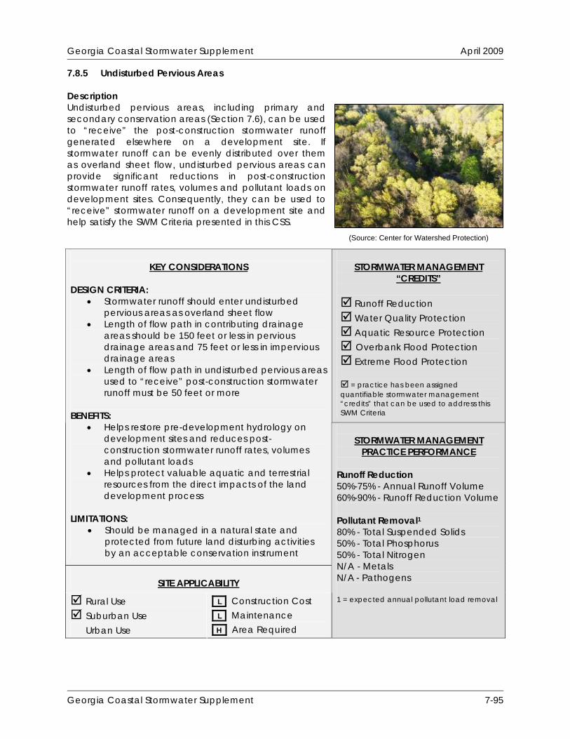
Georgia Coastal Stormwater Supplement April 2009
7.8.5 Undisturbed Pervious Areas Description Undisturbed pervious areas, including primary and secondary conservation areas (Section 7.6), can be used to “receive” the post-construction stormwater runoff generated elsewhere on a development site. If stormwater runoff can be evenly distributed over them as overland sheet flow, undisturbed pervious areas can provide significant reductions in post-construction stormwater runoff rates, volumes and pollutant loads on development sites. Consequently, they can be used to “receive” stormwater runoff on a development site and help satisfy the SWM Criteria presented in this CSS.
STORMWATER MANAGEMENT
“CREDITS”
Runoff Reduction Water Quality Protection Aquatic Resource Protection Overbank Flood Protection Extreme Flood Protection = practice has been assigned quantifiable stormwater management “credits” that can be used to address this SWM Criteria
KEY CONSIDERATIONS
DESIGN CRITERIA:
Stormwater runoff should enter undisturbed pervious areas as overland sheet flow
Length of flow path in contributing drainage areas should be 150 feet or less in pervious drainage areas and 75 feet or less in impervious drainage areas
Length of flow path in undisturbed pervious areas used to “receive” post-construction stormwater runoff must be 50 feet or more
BENEFITS:
Helps restore pre-development hydrology on development sites and reduces post-construction stormwater runoff rates, volumes and pollutant loads
Helps protect valuable aquatic and terrestrial resources from the direct impacts of the land development process
LIMITATIONS:
Should be managed in a natural state and protected from future land disturbing activities by an acceptable conservation instrument
SITE APPLICABILITY
Rural Use Suburban Use Urban Use
L Construction Cost L Maintenance H Area Required
STORMWATER MANAGEMENT
PRACTICE PERFORMANCE Runoff Reduction 50%-75% - Annual Runoff Volume 60%-90% - Runoff Reduction Volume Pollutant Removal1 80% - Total Suspended Solids 50% - Total Phosphorus 50% - Total Nitrogen N/A - Metals N/A - Pathogens 1 = expected annual pollutant load removal
(Source: Center for Watershed Protection)
Georgia Coastal Stormwater Supplement 7-95

Georgia Coastal Stormwater Supplement April 2009
Discussion Undisturbed pervious areas, including primary and secondary conservation areas (Section 7.6), can be used to used to “receive” the post-construction stormwater runoff generated elsewhere on a development site. The native vegetation found in these undisturbed pervious areas increases evaporation and transpiration rates, slows and filters stormwater runoff and helps improve soil porosity and soil infiltration rates. If stormwater runoff can be evenly distributed over them as overland sheet flow, undisturbed pervious areas can provide significant reductions in post-construction stormwater runoff rates, volumes and pollutant loads on development sites. Consequently, they can be used to “receive” stormwater runoff on a development site and help satisfy the SWM Criteria presented in this CSS. If concentrated stormwater runoff is allowed to enter an undisturbed pervious area, it can cause soil erosion and can significantly reduce the stormwater management benefits that the undisturbed pervious area provides. Consequently, stormwater runoff needs to be intercepted and distributed evenly, as overland sheet flow, across an undisturbed pervious area that will be used to “receive” post-construction stormwater runoff. This can be accomplished by limiting the length of the flow path within the contributing drainage area and by using a level spreader at the upstream end of the undisturbed pervious area that will “receive” post-construction stormwater runoff (Figure 7.30).
Figure 7.30: Use of a Level Spreader Upstream of an Undisturbed Pervious Area (Source: North Carolina Department of Environment and Natural Resources, 1998)
Since the undisturbed pervious areas that are used to “receive” stormwater runoff on a development site are typically designed to be on-line stormwater management practices, consideration should be given to the stormwater runoff rates and volumes generated by larger storm events (e.g., 25-year, 24-hour storm event) to help ensure that they do not cause significant damage within the undisturbed pervious areas. Stormwater Management “Credits” The Center for Watershed Protection (Hirschman et al., 2008) recently documented the ability of undisturbed pervious areas that “receive” stormwater runoff to reduce annual stormwater runoff volumes and pollutant loads on development sites. Consequently, this low impact development practice has been assigned quantifiable stormwater management “credits” that can be used to help satisfy the SWM Criteria presented in this CSS:
Georgia Coastal Stormwater Supplement 7-96
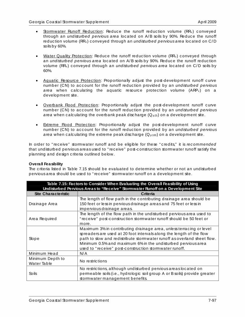
Georgia Coastal Stormwater Supplement April 2009
Stormwater Runoff Reduction: Reduce the runoff reduction volume (RRv) conveyed through an undisturbed pervious area located on A/B soils by 90%. Reduce the runoff reduction volume (RRv) conveyed through an undisturbed pervious area located on C/D soils by 60%.
Water Quality Protection: Reduce the runoff reduction volume (RRv) conveyed through
an undisturbed pervious area located on A/B soils by 90%. Reduce the runoff reduction volume (RRv) conveyed through an undisturbed pervious area located on C/D soils by 60%.
Aquatic Resource Protection: Proportionally adjust the post-development runoff curve
number (CN) to account for the runoff reduction provided by an undisturbed pervious area when calculating the aquatic resource protection volume (ARPv) on a development site.
Overbank Flood Protection: Proportionally adjust the post-development runoff curve
number (CN) to account for the runoff reduction provided by an undisturbed pervious area when calculating the overbank peak discharge (Qp25) on a development site.
Extreme Flood Protection: Proportionally adjust the post-development runoff curve
number (CN) to account for the runoff reduction provided by an undisturbed pervious area when calculating the extreme peak discharge (Qp100) on a development site.
In order to “receive” stormwater runoff and be eligible for these “credits,” it is recommended that undisturbed pervious areas used to “receive” post-construction stormwater runoff satisfy the planning and design criteria outlined below. Overall Feasibility The criteria listed in Table 7.15 should be evaluated to determine whether or not an undisturbed pervious area should be used to “receive” stormwater runoff on a development site.
Table 7.15: Factors to Consider When Evaluating the Overall Feasibility of Using Undisturbed Pervious Areas to “Receive” Stormwater Runoff on a Development Site
Site Characteristic Criteria
Drainage Area The length of flow path in the contributing drainage area should be 150 feet or less in pervious drainage areas and 75 feet or less in impervious drainage areas.
Area Required The length of the flow path in the undisturbed pervious area used to “receive” post-construction stormwater runoff should be 50 feet or more.
Slope
Maximum 3% in contributing drainage area, unless terracing or level spreaders are used at 20 foot intervals along the length of the flow path to slow and redistribute stormwater runoff as overland sheet flow. Minimum 0.5% and maximum 6% in the undisturbed pervious area used to “receive” post-construction stormwater runoff.
Minimum Head N/A Minimum Depth to Water Table No restrictions
Soils No restrictions, although undisturbed pervious areas located on permeable soils (i.e., hydrologic soil group A or B soils) provide greater stormwater management benefits.
Georgia Coastal Stormwater Supplement 7-97

Georgia Coastal Stormwater Supplement April 2009
Site Applicability Although it may be difficult to use undisturbed pervious areas to “receive” stormwater runoff in urban areas, due to space constraints, undisturbed pervious areas can be used to “receive” stormwater runoff on a wide variety of development sites, including residential, commercial, industrial and institutional development sites in rural and suburban areas. When compared with other low impact development practices, undisturbed pervious areas have a relatively low construction cost, a relatively low maintenance burden and require a relatively large amount of surface area. Planning and Design Criteria It is recommended that the undisturbed pervious areas used to “receive” stormwater runoff on a development site meet all of the following criteria to be eligible for the stormwater management “credits” described above: General Planning and Design
The following primary and secondary conservation areas should not be used to “receive” post-construction stormwater runoff on a development site:
o Rivers o Perennial and Intermittent Streams o Freshwater Wetlands o Tidal Rivers and Streams o Tidal Creeks o Coastal Marshlands o Tidal Flats o Scrub-Shrub Wetlands o Near Coastal Waters o Beaches o Shellfishing Areas o Erodible Soils o Steep Slopes (i.e., Areas with Slopes Greater Than 15%)
Although the primary and secondary conservation areas listed above can not be used to “receive” post-construction stormwater runoff on a development site, other undisturbed pervious areas, including aquatic buffers, floodplains, stands of trees and other existing vegetation, and areas preserved through the use of reduced clearing and grading (Section 7.7.1), may be used to help reduce post-construction stormwater runoff rates, volumes and pollutant loads.
The length of the flow path within the contributing drainage area should be 150 feet or less for pervious drainage areas and 75 feet or less for impervious drainage areas.
The average slope of the contributing drainage area should be 3% or less, unless terracing or level spreaders are used at 20 foot intervals along the length of the flow path to slow and redistribute stormwater runoff as overland sheet flow.
In order to use undisturbed pervious areas as “receiving” low impact development practices, stormwater runoff needs to be conveyed into them as overland sheet flow. A level spreader should be used at the upstream end of the undisturbed pervious area to ensure that stormwater runoff enters it as overland sheet flow.
A pea gravel diaphragm makes an effective level spreader at the upstream end of undisturbed pervious areas used to “receive” stormwater runoff. A pea gravel diaphragm, which is a small trench filled with pea gravel (i.e., ASTM D 448 Size No. 8, 3/8” to 1/8”), intercepts stormwater runoff and distributes it evenly, as overland sheet flow, across an undisturbed pervious area. Other types of level spreaders that can be used to redistribute stormwater runoff at the upstream end of undisturbed pervious areas include concrete sills, curb stops and curbs with “sawteeth” cut into them.
Georgia Coastal Stormwater Supplement 7-98
Georgia Coastal Stormwater Supplement April 2009
The length of the flow path within the undisturbed pervious area used to “receive” post-construction stormwater runoff should be 50 feet or more.
The average slope of the undisturbed pervious area used to “receive” post-construction stormwater runoff should be 6% or less. Greater slopes would encourage the formation of concentrated flow, which would cause soil erosion and significantly reduce the stormwater management benefits that undisturbed pervious areas provide.
Consideration should be given to the stormwater runoff rates and volumes generated by larger storm events (e.g., 25-year, 24-hour storm event) to help ensure that these larger storm events do not cause significant damage to the undisturbed pervious areas. If necessary, a bypass channel or overflow spillway may be used to manage the stormwater runoff generated by these larger storm events.
Undisturbed pervious areas should not be used to “receive” post-construction stormwater runoff from stormwater hotspots, unless adequate pretreatment is provided upstream of them.
Undisturbed pervious areas used to “receive” stormwater runoff should not be disturbed before, during or after construction (except for temporary disturbances associated with incidental utility construction, restoration activities, or removal of invasive vegetation).
Landscaping
A long-term vegetation management plan should be developed for all undisturbed pervious areas used to “receive” post-construction stormwater runoff. The plan should clearly specify how the area will be maintained in an undisturbed, natural state over time. Turf management is not considered to be an acceptable form of vegetation management. Consequently, only undisturbed pervious areas that remain in an undisturbed, natural state are eligible for the stormwater management “credits” described above. Vegetated filter strips (Section 7.8.6) may be used to “receive” post-construction stormwater runoff in areas that have been disturbed by clearing, grading and other land disturbing activities.
Construction Considerations To help ensure that undisturbed pervious areas are properly used to “receive” stormwater runoff on a development site, site planning and design teams should consider the following recommendations:
To help prevent soil compaction, heavy vehicular and foot traffic should be kept out of all undisturbed pervious areas used to “receive” post-construction stormwater runoff before, during and after construction. This can typically be accomplished by clearly delineating “receiving” undisturbed pervious areas on all development plans and protecting them with temporary fencing prior to the start of land disturbing activities.
Maintenance Requirements Undisturbed pervious areas used to “receive” post-construction stormwater runoff typically require very little long-term maintenance, but a legally binding inspection and maintenance agreement and plan should be created to help ensure that they are properly maintained after construction is complete. Table 7.16 provides a list of the routine maintenance activities typically associated with undisturbed pervious areas used to “receive” post-construction stormwater runoff.
Georgia Coastal Stormwater Supplement 7-99

Georgia Coastal Stormwater Supplement April 2009
Table 7.16: Routine Maintenance Activities Typically Associated with Undisturbed Pervious Areas Used to “Receive” Stormwater Runoff
Activity Schedule Inspect level spreader for clogging and sediment
accumulation. Remove any accumulated sediment or debris.
Inspect undisturbed natural area for erosion. Plant replacement vegetation in any eroded areas.
Inspect undisturbed natural area for dead or dying vegetation. Plant replacement vegetation as needed.
Annually (Semi-Annually During First Year)
Additional Resources Minnesota Pollution Control Agency (MPCA). 2006. “Credit 3: Drainage to Stream, Wetland or
Shoreline Buffer Credit.” Minnesota Stormwater Manual. Section 11.3.2. Minnesota Pollution Control Agency. Available Online: Available Online: http://www.pca.state.mn.us/water/stormwater/stormwater-manual.html.
Atlanta Regional Commission (ARC). 2001. “Site Design Credit #2: Stream Buffers.” Georgia
Stormwater Management Manual. Volume 2. Technical Handbook. Section 1.4.4.4. Atlanta Regional Commission. Atlanta, GA. Available Online: http://www.georgiastormwater.com/.
Georgia Coastal Stormwater Supplement 7-100
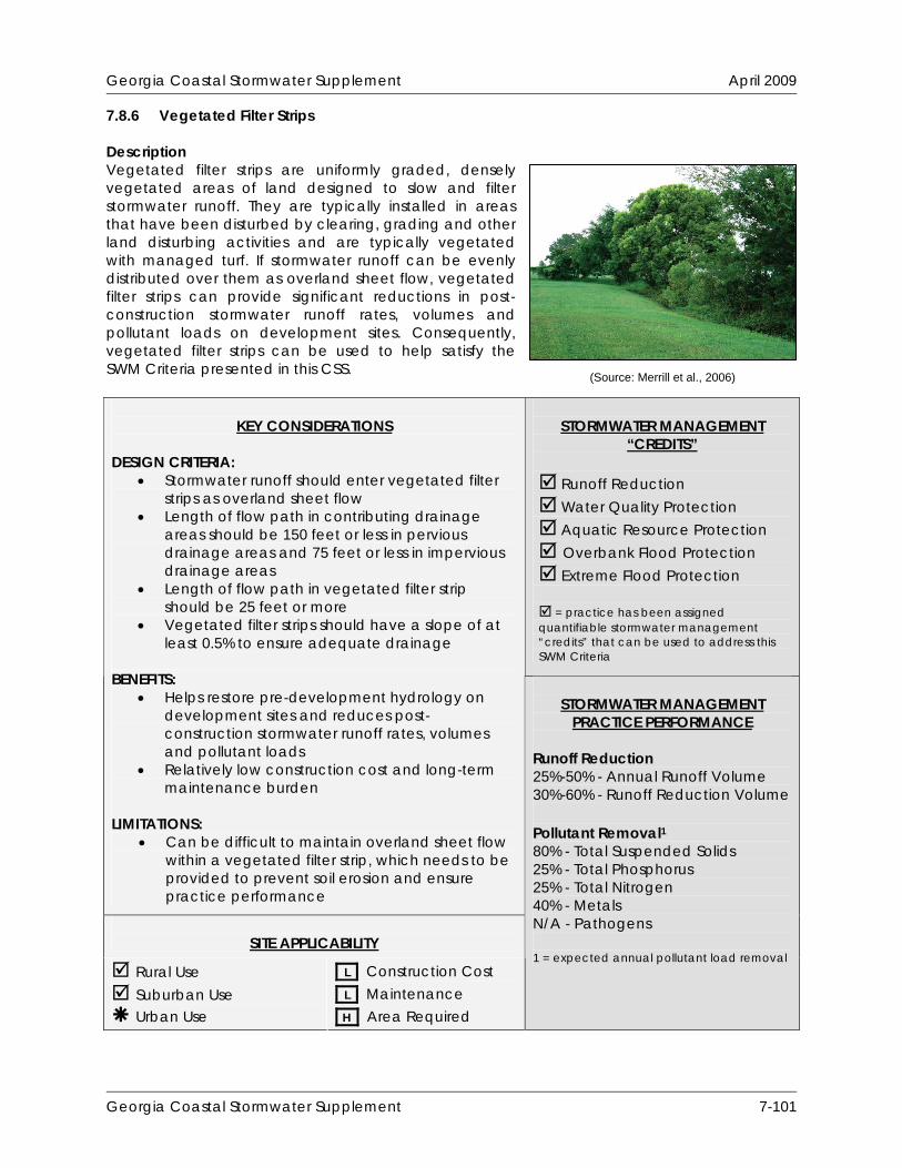
Georgia Coastal Stormwater Supplement April 2009
7.8.6 Vegetated Filter Strips Description Vegetated filter strips are uniformly graded, densely vegetated areas of land designed to slow and filter stormwater runoff. They are typically installed in areas that have been disturbed by clearing, grading and other land disturbing activities and are typically vegetated with managed turf. If stormwater runoff can be evenly distributed over them as overland sheet flow, vegetated filter strips can provide significant reductions in post-construction stormwater runoff rates, volumes and pollutant loads on development sites. Consequently, vegetated filter strips can be used to help satisfy the SWM Criteria presented in this CSS.
STORMWATER MANAGEMENT
“CREDITS”
Runoff Reduction Water Quality Protection Aquatic Resource Protection Overbank Flood Protection Extreme Flood Protection = practice has been assigned quantifiable stormwater management “credits” that can be used to address this SWM Criteria
KEY CONSIDERATIONS
DESIGN CRITERIA:
Stormwater runoff should enter vegetated filter strips as overland sheet flow
Length of flow path in contributing drainage areas should be 150 feet or less in pervious drainage areas and 75 feet or less in impervious drainage areas
Length of flow path in vegetated filter strip should be 25 feet or more
Vegetated filter strips should have a slope of at least 0.5% to ensure adequate drainage
BENEFITS:
Helps restore pre-development hydrology on development sites and reduces post-construction stormwater runoff rates, volumes and pollutant loads
Relatively low construction cost and long-term maintenance burden
LIMITATIONS:
Can be difficult to maintain overland sheet flow within a vegetated filter strip, which needs to be provided to prevent soil erosion and ensure practice performance
SITE APPLICABILITY
Rural Use Suburban Use Urban Use
L Construction Cost L Maintenance H Area Required
STORMWATER MANAGEMENT
PRACTICE PERFORMANCE Runoff Reduction 25%-50% - Annual Runoff Volume 30%-60% - Runoff Reduction Volume Pollutant Removal1 80% - Total Suspended Solids 25% - Total Phosphorus 25% - Total Nitrogen 40% - Metals N/A - Pathogens 1 = expected annual pollutant load removal
(Source: Merrill et al., 2006)
Georgia Coastal Stormwater Supplement 7-101
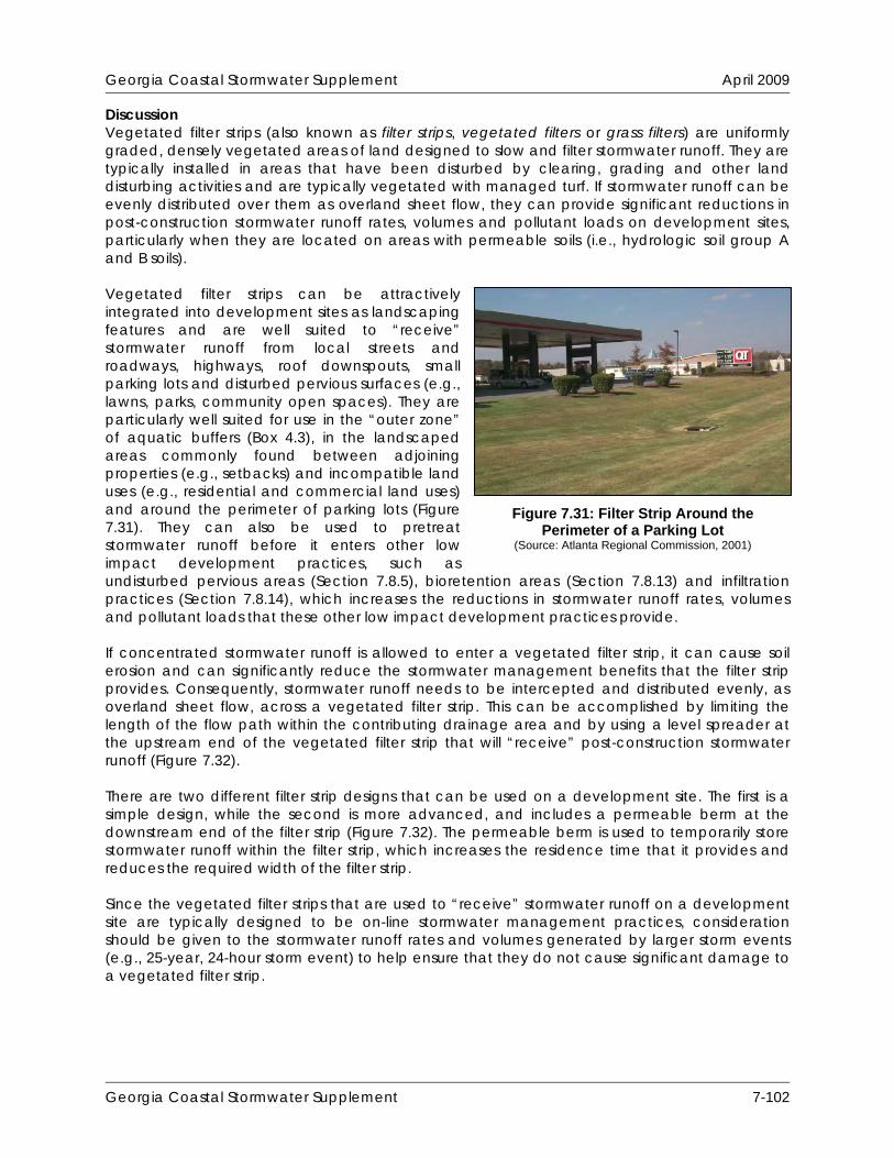
Georgia Coastal Stormwater Supplement April 2009
Discussion Vegetated filter strips (also known as filter strips, vegetated filters or grass filters) are uniformly graded, densely vegetated areas of land designed to slow and filter stormwater runoff. They are typically installed in areas that have been disturbed by clearing, grading and other land disturbing activities and are typically vegetated with managed turf. If stormwater runoff can be evenly distributed over them as overland sheet flow, they can provide significant reductions in post-construction stormwater runoff rates, volumes and pollutant loads on development sites, particularly when they are located on areas with permeable soils (i.e., hydrologic soil group A and B soils). Vegetated filter strips can be attractively integrated into development sites as landscaping features and are well suited to “receive” stormwater runoff from local streets and roadways, highways, roof downspouts, small parking lots and disturbed pervious surfaces (e.g., lawns, parks, community open spaces). They are particularly well suited for use in the “outer zone” of aquatic buffers (Box 4.3), in the landscaped areas commonly found between adjoining properties (e.g., setbacks) and incompatible land uses (e.g., residential and commercial land uses) and around the perimeter of parking lots (Figure 7.31). They can also be used to pretreat stormwater runoff before it enters other low impact development practices, such as undisturbed pervious areas (Section 7.8.5), bioretention areas (Section 7.8.13) and infiltration practices (Section 7.8.14), which increases the reductions in stormwater runoff rates, volumes and pollutant loads that these other low impact development practices provide. If concentrated stormwater runoff is allowed to enter a vegetated filter strip, it can cause soil erosion and can significantly reduce the stormwater management benefits that the filter strip provides. Consequently, stormwater runoff needs to be intercepted and distributed evenly, as overland sheet flow, across a vegetated filter strip. This can be accomplished by limiting the length of the flow path within the contributing drainage area and by using a level spreader at the upstream end of the vegetated filter strip that will “receive” post-construction stormwater runoff (Figure 7.32). There are two different filter strip designs that can be used on a development site. The first is a simple design, while the second is more advanced, and includes a permeable berm at the downstream end of the filter strip (Figure 7.32). The permeable berm is used to temporarily store stormwater runoff within the filter strip, which increases the residence time that it provides and reduces the required width of the filter strip. Since the vegetated filter strips that are used to “receive” stormwater runoff on a development site are typically designed to be on-line stormwater management practices, consideration should be given to the stormwater runoff rates and volumes generated by larger storm events (e.g., 25-year, 24-hour storm event) to help ensure that they do not cause significant damage to a vegetated filter strip.
Figure 7.31: Filter Strip Around the Perimeter of a Parking Lot
(Source: Atlanta Regional Commission, 2001)
Georgia Coastal Stormwater Supplement 7-102

Georgia Coastal Stormwater Supplement April 2009
Georgia Coastal Stormwater Supplement 7-103
Stormwater Management “Credits” The Center for Watershed Protection (Hirschman et al., 2008) recently documented the ability of vegetated filter strips to reduce annual stormwater runoff volumes and pollutant loads on development sites. Consequently, this low impact development practice has been assigned quantifiable stormwater management “credits” that can be used to help satisfy the SWM Criteria presented in this CSS:
Figure 7.32: Vegetated Filter Strip (Source: Atlanta Regional Commission, 2001)

Georgia Coastal Stormwater Supplement April 2009
Stormwater Runoff Reduction: Reduce the runoff reduction volume (RRv) conveyed through a vegetated filter strip located on A/B or amended soils by 60%. Reduce the runoff reduction volume (RRv) conveyed through a vegetated filter strip located on C/D soils by 30%.
Water Quality Protection: Reduce the runoff reduction volume (RRv) conveyed through a
vegetated filter strip located on A/B or amended soils by 60%. Reduce the runoff reduction volume (RRv) conveyed through a vegetated filter strip located on C/D soils by 30%.
Aquatic Resource Protection: Proportionally adjust the post-development runoff curve
number (CN) to account for the runoff reduction provided by a vegetated filter strip when calculating the aquatic resource protection volume (ARPv) on a development site.
Overbank Flood Protection: Proportionally adjust the post-development runoff curve
number (CN) to account for the runoff reduction provided by a vegetated filter strip when calculating the overbank peak discharge (Qp25) on a development site.
Extreme Flood Protection: Proportionally adjust the post-development runoff curve
number (CN) to account for the runoff reduction provided by a vegetated filter strip when calculating the extreme peak discharge (Qp100) on a development site.
In order to “receive” stormwater runoff and be eligible for these “credits,” it is recommended that vegetated filter strips satisfy the planning and design criteria outlined below. Overall Feasibility The criteria listed in Table 7.17 should be evaluated to determine whether or not a vegetated filter strip should be used to “receive” stormwater runoff on a development site.
Table 7.17: Factors to Consider When Evaluating the Overall Feasibility of Using a Vegetated Filter Strip on a Development Site
Site Characteristic Criteria
Drainage Area The length of flow path in the contributing drainage area should be 150 feet or less in pervious drainage areas and 75 feet or less in impervious drainage areas.
Area Required
Unless a permeable berm is provided, the length of the flow path in the vegetated filter strip used to “receive” stormwater runoff should be 25 feet or more. If a permeable berm is provided, the length of the flow path in the vegetated filter strip used to “receive” stormwater runoff should be 15 feet or more.
Slope
Maximum 3% in contributing drainage area, unless terracing or level spreaders are used at 20 foot intervals along the length of the flow path to slow and redistribute stormwater runoff as overland sheet flow. Minimum 0.5% and maximum 6% in the vegetated filter strip used to “receive” post-construction stormwater runoff.
Minimum Head N/A Minimum Depth to Water Table No restrictions
Soils No restrictions, although vegetated filter strips located on permeable soils (i.e., hydrologic soil group A or B soils) provide greater stormwater management benefits.
Georgia Coastal Stormwater Supplement 7-104

Georgia Coastal Stormwater Supplement April 2009
Feasibility in Coastal Georgia Several site characteristics commonly encountered in coastal Georgia may present challenges to site planning and design teams that are interested in using vegetated filter strips to “receive” post-construction stormwater runoff on a development site. Table 7.18 identifies these common site characteristics and describes how they influence the use of vegetated filter strips on development sites. The table also provides site planning and design teams with some ideas about how they can work around these potential constraints.
Table 7.18: Challenges Associated with Using Vegetated Filter Strips in Coastal Georgia
Site Characteristic How it Influences the Use of Vegetated Filter Strips Potential Solutions
Poorly drained soils, such as hydrologic soil group C and D soils
Reduces the ability of vegetated filter strips to reduce stormwater runoff rates, volumes and pollutant loads.
Use soil restoration (Section 7.8.1) to improve soil porosity and the ability of vegetated filter strips to reduce stormwater runoff rates, volumes and pollutant loads.
Place buildings and other impervious surfaces on poorly drained soils or preserve them as secondary conservation areas (Section 7.6.2).
Use additional low impact development practices to supplement the stormwater management benefits provided by vegetated filter strips.
Well drained soils, such as hydrologic soil group A and B soils
Enhances the ability of vegetated filter strips to reduce stormwater runoff rates, volumes and pollutant loads, but may allow stormwater pollutants to reach groundwater aquifers with greater ease.
Avoid the use of infiltration-based low impact development practices, including vegetated filter strips, at stormwater hotspots and in areas known to provide groundwater recharge to water supply aquifers, unless adequate pretreatment is provided upstream of them.
Flat terrain May be difficult to provide adequate drainage and may cause stormwater runoff to pond on the surface of a vegetated filter strip.
Design vegetated filter strips with a slope of at least 0.5% to help ensure adequate drainage.
Where soils are well drained, use non-underdrained bioretention areas (Section 7.8.13) and infiltration practices (Section 7.8.14), to reduce stormwater runoff rates, volumes and pollutant loads and prevent ponding in these areas.
Where soils are poorly drained, use small stormwater wetlands (i.e., pocket wetlands) (Section 8.6.2) to intercept and treat stormwater runoff.
Georgia Coastal Stormwater Supplement 7-105
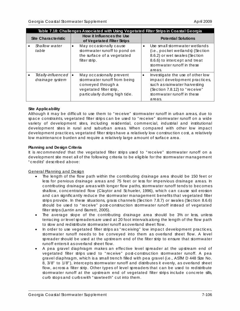
Georgia Coastal Stormwater Supplement April 2009
Table 7.18: Challenges Associated with Using Vegetated Filter Strips in Coastal Georgia How it Influences the Use Site Characteristic Potential Solutions of Vegetated Filter Strips
Shallow water table
May occasionally cause stormwater runoff to pond on the surface of a vegetated filter strip.
Use small stormwater wetlands (i.e., pocket wetlands) (Section 8.6.2) or wet swales (Section 8.6.6) to intercept and treat stormwater runoff in these areas.
Tidally-influenced drainage system
May occasionally prevent stormwater runoff from being conveyed through a vegetated filter strip, particularly during high tide.
Investigate the use of other low impact development practices, such as rainwater harvesting (Section 7.8.12) to “receive” stormwater runoff in these areas.
Site Applicability Although it may be difficult to use them to “receive” stormwater runoff in urban areas, due to space constraints, vegetated filter strips can be used to “receive” stormwater runoff on a wide variety of development sites, including residential, commercial, industrial and institutional development sites in rural and suburban areas. When compared with other low impact development practices, vegetated filter strips have a relatively low construction cost, a relatively low maintenance burden and require a relatively large amount of surface area. Planning and Design Criteria It is recommended that the vegetated filter strips used to “receive” stormwater runoff on a development site meet all of the following criteria to be eligible for the stormwater management “credits” described above:
General Planning and Design
The length of the flow path within the contributing drainage area should be 150 feet or less for pervious drainage areas and 75 feet or less for impervious drainage areas. In contributing drainage areas with longer flow paths, stormwater runoff tends to becomes shallow, concentrated flow (Claytor and Schueler, 1996), which can cause soil erosion and can significantly reduce the stormwater management benefits that vegetated filter strips provide. In these situations, grass channels (Section 7.8.7) or swales (Section 8.6.6) should be used to “receive” post-construction stormwater runoff instead of vegetated filter strips (Lantin and Barrett, 2005).
The average slope of the contributing drainage area should be 3% or less, unless terracing or level spreaders are used at 20 foot intervals along the length of the flow path to slow and redistribute stormwater runoff as overland sheet flow.
In order to use vegetated filter strips as “receiving” low impact development practices, stormwater runoff needs to be conveyed into them as overland sheet flow. A level spreader should be used at the upstream end of the filter strip to ensure that stormwater runoff enters it as overland sheet flow.
A pea gravel diaphragm makes an effective level spreader at the upstream end of vegetated filter strips used to “receive” post-construction stormwater runoff. A pea gravel diaphragm, which is a small trench filled with pea gravel (i.e., ASTM D 448 Size No. 8, 3/8” to 1/8”), intercepts stormwater runoff and distributes it evenly, as overland sheet flow, across a filter strip. Other types of level spreaders that can be used to redistribute stormwater runoff at the upstream end of vegetated filter strips include concrete sills, curb stops and curbs with “sawteeth” cut into them.
Georgia Coastal Stormwater Supplement 7-106
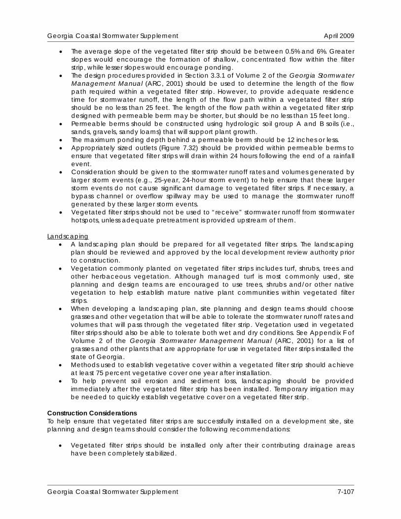
Georgia Coastal Stormwater Supplement April 2009
The average slope of the vegetated filter strip should be between 0.5% and 6%. Greater slopes would encourage the formation of shallow, concentrated flow within the filter strip, while lesser slopes would encourage ponding.
The design procedures provided in Section 3.3.1 of Volume 2 of the Georgia Stormwater Management Manual (ARC, 2001) should be used to determine the length of the flow path required within a vegetated filter strip. However, to provide adequate residence time for stormwater runoff, the length of the flow path within a vegetated filter strip should be no less than 25 feet. The length of the flow path within a vegetated filter strip designed with permeable berm may be shorter, but should be no less than 15 feet long.
Permeable berms should be constructed using hydrologic soil group A and B soils (i.e., sands, gravels, sandy loams) that will support plant growth.
The maximum ponding depth behind a permeable berm should be 12 inches or less. Appropriately sized outlets (Figure 7.32) should be provided within permeable berms to
ensure that vegetated filter strips will drain within 24 hours following the end of a rainfall event.
Consideration should be given to the stormwater runoff rates and volumes generated by larger storm events (e.g., 25-year, 24-hour storm event) to help ensure that these larger storm events do not cause significant damage to vegetated filter strips. If necessary, a bypass channel or overflow spillway may be used to manage the stormwater runoff generated by these larger storm events.
Vegetated filter strips should not be used to “receive” stormwater runoff from stormwater hotspots, unless adequate pretreatment is provided upstream of them.
Landscaping
A landscaping plan should be prepared for all vegetated filter strips. The landscaping plan should be reviewed and approved by the local development review authority prior to construction.
Vegetation commonly planted on vegetated filter strips includes turf, shrubs, trees and other herbaceous vegetation. Although managed turf is most commonly used, site planning and design teams are encouraged to use trees, shrubs and/or other native vegetation to help establish mature native plant communities within vegetated filter strips.
When developing a landscaping plan, site planning and design teams should choose grasses and other vegetation that will be able to tolerate the stormwater runoff rates and volumes that will pass through the vegetated filter strip. Vegetation used in vegetated filter strips should also be able to tolerate both wet and dry conditions. See Appendix F of Volume 2 of the Georgia Stormwater Management Manual (ARC, 2001) for a list of grasses and other plants that are appropriate for use in vegetated filter strips installed the state of Georgia.
Methods used to establish vegetative cover within a vegetated filter strip should achieve at least 75 percent vegetative cover one year after installation.
To help prevent soil erosion and sediment loss, landscaping should be provided immediately after the vegetated filter strip has been installed. Temporary irrigation may be needed to quickly establish vegetative cover on a vegetated filter strip.
Construction Considerations To help ensure that vegetated filter strips are successfully installed on a development site, site planning and design teams should consider the following recommendations:
Vegetated filter strips should be installed only after their contributing drainage areas have been completely stabilized.
Georgia Coastal Stormwater Supplement 7-107

Georgia Coastal Stormwater Supplement April 2009
Simple erosion and sediment control measures, such as temporary seeding and erosion control mats, should be used on vegetated filter strips. Appropriate measures should be taken (e.g., silt fence, temporary diversion berm) to pretreat and/or divert post-construction stormwater runoff around a vegetated filter strip until vegetative cover has been established.
To help prevent soil compaction, heavy vehicular and foot traffic should be kept out of vegetated filter strips during and after construction.
Construction contracts should contain a replacement warranty that covers at least three growing seasons to help ensure adequate growth and survival of the vegetation planted within a vegetated filter strip.
Maintenance Requirements Maintenance is very important for vegetated filter strips, particularly in terms of ensuring that they continue to provide measurable stormwater management benefits over time. Consequently, a legally binding inspection and maintenance agreement and plan should be created to help ensure that they are properly maintained after construction is complete. Table 7.19 provides a list of the routine maintenance activities typically associated with vegetated filter strips. It is important to note that vegetated filter strips have maintenance requirements that are very similar to those of other vegetated low impact development practices.
Table 7.19: Routine Maintenance Activities Typically Associated with Vegetated Filter Strips Activity Schedule
Water to promote plant growth and survival. Inspect vegetated filter strip following rainfall events.
Plant replacement vegetation in any eroded areas.
As Needed (Following Construction)
Inspect vegetated filter strip. Maintain vegetation (e.g., mow, prune, trim) as needed.
Remove accumulated trash and debris.
Regularly (Monthly)
Inspect level spreader for clogging and sediment accumulation. Remove any accumulated sediment or debris.
Inspect vegetated filter strip for erosion. Plant replacement vegetation in any eroded areas.
Inspect vegetated filter strip for dead or dying vegetation. Plant replacement vegetation as needed.
Annually (Semi-Annually During First Year)
Additional Resources Claytor, R. and T. Schueler. 1996. Design of Stormwater Filtering Systems. Prepared for:
Chesapeake Research Consortium, Inc. Center for Watershed Protection. Ellicott City, MD. Available Online: http://www.cwp.org/Resource_Library/Controlling_Runoff_and_Discharges/sm.htm.
Minnesota Pollution Control Agency (MPCA). 2006. “Credit 4: Surface Impervious Cover
Disconnection Credit.” Minnesota Stormwater Manual. Section 11.3.2. Minnesota Pollution Control Agency. Available Online: http://www.pca.state.mn.us/water/stormwater/stormwater-manual.html.
Atlanta Regional Commission (ARC). 2001. “Filter Strip.” Georgia Stormwater Management
Manual. Volume 2. Technical Handbook. Section 3.3.1. Atlanta Regional Commission. Atlanta, GA. Available Online: http://www.georgia stormwater.com/.
Georgia Coastal Stormwater Supplement 7-108

Georgia Coastal Stormwater Supplement April 2009
7.8.7 Grass Channels Description Where site characteristics permit, grass channels, which are densely vegetated stormwater conveyance features, can be used to “receive” and convey post-construction stormwater runoff. They are typically installed in areas that have been disturbed by clearing, grading and other land disturbing activities, and are typically vegetated with managed turf. If properly designed, grass channels can provide measurable reductions in post-construction stormwater runoff rates, volumes and pollutant loads. Consequently, they can be used to help satisfy the SWM Criteria presented in this CSS.
STORMWATER MANAGEMENT
“CREDITS”
Runoff Reduction Water Quality Protection Aquatic Resource Protection Overbank Flood Protection Extreme Flood Protection = practice has been assigned quantifiable stormwater management “credits” that can be used to address this SWM Criteria
KEY CONSIDERATIONS
DESIGN CRITERIA:
Grass channels should be designed to accommodate the peak discharge generated by the target runoff reduction rainfall event (e.g., 85th percentile rainfall event)
Grass channels should be designed to able to safely convey the overbank flood protection rainfall event (e.g., 25-year, 24-hour event)
Grass channels may be designed with a slope of between 0.5% and 3%, although a slope of between 1% and 2% is recommended
BENEFITS:
Helps restore pre-development hydrology on development sites and reduces post-construction stormwater runoff rates, volumes and pollutant loads
Relatively low construction cost and long-term maintenance burden
LIMITATIONS:
Should not be used on development sites with slopes of less than 0.5%
Provides greater stormwater management benefits on sites with permeable soils (i.e., hydrologic soil group A and B soils)
SITE APPLICABILITY
Rural Use Suburban Use Urban Use
L Construction Cost M Maintenance M Area Required
STORMWATER MANAGEMENT
PRACTICE PERFORMANCE Runoff Reduction 10%-20% - Annual Runoff Volume 12%-25% - Runoff Reduction Volume Pollutant Removal1 60% - Total Suspended Solids 25% - Total Phosphorus 30% - Total Nitrogen 30% - Metals N/A - Pathogens 1 = expected annual pollutant load removal
(Source: Center for Watershed Protection)
Georgia Coastal Stormwater Supplement 7-109
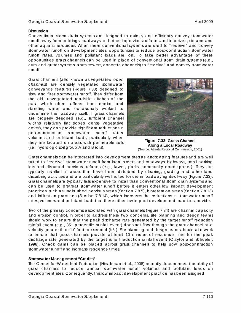
Georgia Coastal Stormwater Supplement April 2009
Discussion Conventional storm drain systems are designed to quickly and efficiently convey stormwater runoff away from buildings, roadways and other impervious surfaces and into rivers, streams and other aquatic resources. When these conventional systems are used to “receive” and convey stormwater runoff on development sites, opportunities to reduce post-construction stormwater runoff rates, volumes and pollutant loads are lost. To take better advantage of these opportunities, grass channels can be used in place of conventional storm drain systems (e.g., curb and gutter systems, storm sewers, concrete channels) to “receive” and convey stormwater runoff. Grass channels (also known as vegetated open channels) are densely vegetated stormwater conveyance features (Figure 7.33) designed to slow and filter stormwater runoff. They differ from the old, unvegetated roadside ditches of the past, which often suffered from erosion and standing water and occasionally worked to undermine the roadway itself. If grass channels are properly designed (e.g., sufficient channel widths, relatively flat slopes, dense vegetative cover), they can provide significant reductions in post-construction stormwater runoff rates, volumes and pollutant loads, particularly when they are located on areas with permeable soils (i.e., hydrologic soil group A and B soils). Grass channels can be integrated into development sites as landscaping features and are well suited to “receive” stormwater runoff from local streets and roadways, highways, small parking lots and disturbed pervious surfaces (e.g., lawns, parks, community open spaces). They are typically installed in areas that have been disturbed by clearing, grading and other land disturbing activities and are particularly well suited for use in roadway rights-of-way (Figure 7.33). Grass channels are typically less expensive to install than conventional storm drain systems and can be used to pretreat stormwater runoff before it enters other low impact development practices, such as undisturbed pervious areas (Section 7.8.5), bioretention areas (Section 7.8.13) and infiltration practices (Section 7.8.14), which increases the reductions in stormwater runoff rates, volumes and pollutant loads that these other low impact development practices provide. Two of the primary concerns associated with grass channels (Figure 7.34) are channel capacity and erosion control. In order to address these two concerns, site planning and design teams should work to ensure that the peak discharge rate generated by the target runoff reduction rainfall event (e.g., 85th percentile rainfall event) does not flow through the grass channel at a velocity greater than 1.0 foot per second (ft/s). Site planning and design teams should also work to ensure that grass channels provide at least 10 minutes of residence time for the peak discharge rate generated by the target runoff reduction rainfall event (Claytor and Schueler, 1996). Check dams can be placed across grass channels to help slow post-construction stormwater runoff and increase residence times. Stormwater Management “Credits” The Center for Watershed Protection (Hirschman et al., 2008) recently documented the ability of grass channels to reduce annual stormwater runoff volumes and pollutant loads on development sites. Consequently, this low impact development practice has been assigned
Figure 7.33: Grass Channel Along a Local Roadway
(Source: Atlanta Regional Commission, 2001)
Georgia Coastal Stormwater Supplement 7-110

Georgia Coastal Stormwater Supplement April 2009
quantifiable stormwater management “credits” that can be used to help satisfy the SWM Criteria presented in this CSS:
Stormwater Runoff Reduction: Reduce the runoff reduction volume (RRv) conveyed through a grass channel located on A/B or amended soils by 25%. Reduce the runoff reduction volume (RRv) conveyed through a grass channel located on C/D soils by 12.5%.
Water Quality Protection: Reduce the runoff reduction volume (RRv) conveyed through a
grass channel located on A/B or amended soils by 25%. Reduce the runoff reduction volume (RRv) conveyed through a grass channel located on C/D soils by 12.5%.
Figure 7.34: Grass Channel (Source: Atlanta Regional Commission, 2001)
Georgia Coastal Stormwater Supplement 7-111
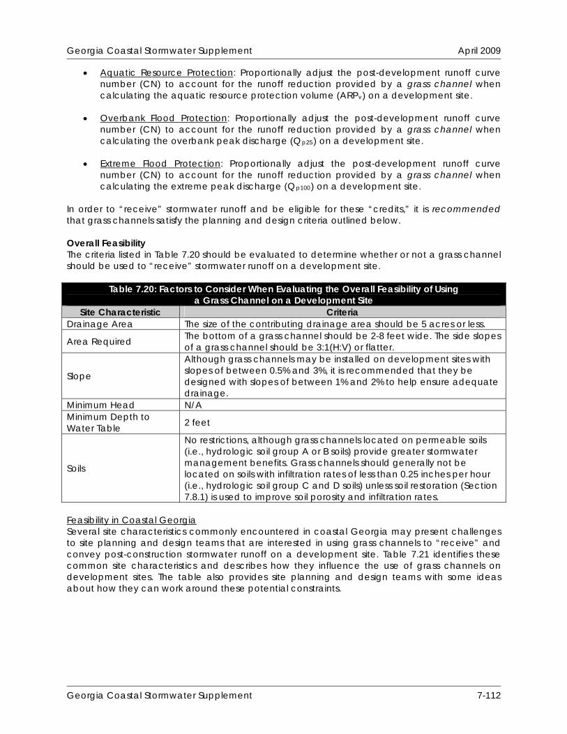
Georgia Coastal Stormwater Supplement April 2009
Aquatic Resource Protection: Proportionally adjust the post-development runoff curve number (CN) to account for the runoff reduction provided by a grass channel when calculating the aquatic resource protection volume (ARPv) on a development site.
Overbank Flood Protection: Proportionally adjust the post-development runoff curve
number (CN) to account for the runoff reduction provided by a grass channel when calculating the overbank peak discharge (Qp25) on a development site.
Extreme Flood Protection: Proportionally adjust the post-development runoff curve
number (CN) to account for the runoff reduction provided by a grass channel when calculating the extreme peak discharge (Qp100) on a development site.
In order to “receive” stormwater runoff and be eligible for these “credits,” it is recommended that grass channels satisfy the planning and design criteria outlined below. Overall Feasibility The criteria listed in Table 7.20 should be evaluated to determine whether or not a grass channel should be used to “receive” stormwater runoff on a development site.
Table 7.20: Factors to Consider When Evaluating the Overall Feasibility of Using a Grass Channel on a Development Site
Site Characteristic Criteria Drainage Area The size of the contributing drainage area should be 5 acres or less.
Area Required The bottom of a grass channel should be 2-8 feet wide. The side slopes of a grass channel should be 3:1(H:V) or flatter.
Slope
Although grass channels may be installed on development sites with slopes of between 0.5% and 3%, it is recommended that they be designed with slopes of between 1% and 2% to help ensure adequate drainage.
Minimum Head N/A Minimum Depth to Water Table 2 feet
Soils
No restrictions, although grass channels located on permeable soils (i.e., hydrologic soil group A or B soils) provide greater stormwater management benefits. Grass channels should generally not be located on soils with infiltration rates of less than 0.25 inches per hour (i.e., hydrologic soil group C and D soils) unless soil restoration (Section 7.8.1) is used to improve soil porosity and infiltration rates.
Feasibility in Coastal Georgia Several site characteristics commonly encountered in coastal Georgia may present challenges to site planning and design teams that are interested in using grass channels to “receive” and convey post-construction stormwater runoff on a development site. Table 7.21 identifies these common site characteristics and describes how they influence the use of grass channels on development sites. The table also provides site planning and design teams with some ideas about how they can work around these potential constraints.
Georgia Coastal Stormwater Supplement 7-112

Georgia Coastal Stormwater Supplement April 2009
Table 7.21: Challenges Associated with Using Grass Channels in Coastal Georgia
Site Characteristic How it Influences the Use of Grass Channels Potential Solutions
Poorly drained soils, such as hydrologic soil group C and D soils
Reduces the ability of grass channels to reduce stormwater runoff rates, volumes and pollutant loads.
Use soil restoration (Section 7.8.1) to improve soil porosity and the ability of grass channels to reduce stormwater runoff rates, volumes and pollutant loads.
Use wet swales (i.e., linear wetland systems) (Section 8.6.6) to intercept, convey and treat stormwater runoff in these areas.
Well drained soils, such as hydrologic soil group A and B soils
Enhances the ability of grass channels to reduce stormwater runoff rates, volumes and pollutant loads, but may allow stormwater pollutants to reach groundwater aquifers with greater ease.
Avoid the use of infiltration-based low impact development practices, including grass channels, at stormwater hotspots and in areas known to provide groundwater recharge to water supply aquifers, unless adequate pretreatment is provided upstream of them.
Use dry swales (Section 7.8.15) with liners and underdrains at stormwater hotspots and in areas known to provide groundwater recharge to water supply aquifers.
Flat terrain May be difficult to provide positive drainage and may cause stormwater runoff to pond in the bottom of the grass channel.
Design grass channels with a slope of at least 0.5% to help ensure adequate drainage.
Where soils are sufficiently permeable, use infiltration practices (Section 7.8.14) and non-underdrained bioretention areas (Section 7.8.13)and dry swales (Section 7.8.15), to reduce stormwater runoff volumes and prevent ponding in these areas.
Where soils have low permeabilities, use wet swales (Section 8.6.6) instead of grass channels to intercept, convey and treat stormwater runoff.
Shallow water table
May occasionally cause stormwater runoff to pond in the bottom of the grass channel.
Use wet swales (i.e., linear wetland systems) (Section 8.6.6) to intercept, convey and treat stormwater runoff in these areas.
Georgia Coastal Stormwater Supplement 7-113

Georgia Coastal Stormwater Supplement April 2009
Table 7.21: Challenges Associated with Using Grass Channels in Coastal Georgia How it Influences the Use Site Characteristic Potential Solutions of Grass Channels
Tidally-influenced drainage system
May occasionally prevent stormwater runoff from being conveyed through a grass channel, particularly during high tide.
Investigate the use of other low impact development practices, such as rainwater harvesting (Section 7.8.12) to “receive” stormwater runoff in these areas.
Site Applicability Although it may be difficult to use them to “receive” stormwater runoff in urban areas, due to space constraints, grass channels can be used to “receive” stormwater runoff on a wide variety of development sites, including residential, commercial, industrial and institutional development sites in rural and suburban areas. When compared with other low impact development practices, grass channels have a relatively low construction cost, a moderate maintenance burden and require only a moderate amount of surface area. Planning and Design Criteria It is recommended that the grass channels used to “receive” stormwater runoff on a development site meet all of the following criteria to be eligible for the stormwater management “credits” described above: General Planning and Design
Grass channels should be used to “receive” stormwater runoff from relatively small drainage areas of 5 acres or less. The stormwater runoff rates and volumes from larger contributing drainage areas typically become too large to be properly conveyed within a grass channel.
Although grass channels may be installed on development sites with slopes of between 0.5% and 3%, it is recommended that they be designed with slopes of between 1% and 2% to help ensure adequate drainage. Slopes greater than 3% would encourage erosion within the grass channel, while slopes less than 0.5% would encourage ponding.
Grass channels should be designed to accommodate the peak discharge rate generated by the target runoff reduction rainfall event (e.g., 85th percentile rainfall event). The required dimensions of a grass channel can be determined using the design procedures provided in Section 3.3.2 of Volume 2 of the Georgia Stormwater Management Manual (ARC, 2001).
To help prevent erosion within grass channels, the peak discharge rate generated by the target runoff reduction rainfall event (e.g., 85th percentile rainfall event) should be designed to flow through a grass channel at a velocity of 1.0 foot per second (ft/s) or less.
To provide adequate residence time for stormwater runoff, grass channels should be designed to provide at least 10 minutes of residence time for the peak discharge rate generated by the target runoff reduction rainfall event (e.g., 85th percentile rainfall event) (Claytor and Schueler, 1996). Residence times may be increased by adjusting channel dimensions, slopes and vegetative covers or by including check dams in the channel design.
The bottom of a grass channel should be designed to be between 2 and 8 feet wide. Channel bottoms greater than 8 feet wide encourage channel braiding, while channel bottoms less than 2 feet wide encourage soil erosion. If a channel bottom needs to be more than 8 feet wide to accommodate the peak discharge rate generated by the
Georgia Coastal Stormwater Supplement 7-114
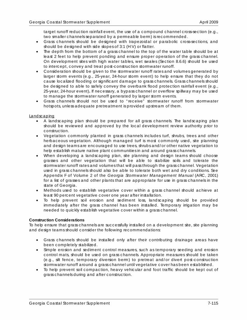
Georgia Coastal Stormwater Supplement April 2009
target runoff reduction rainfall event, the use of a compound channel cross-section (e.g., two smaller channels separated by a permeable berm) is recommended.
Grass channels should be designed with trapezoidal or parabolic cross-sections, and should be designed with side slopes of 3:1 (H:V) or flatter.
The depth from the bottom of a grass channel to the top of the water table should be at least 2 feet to help prevent ponding and ensure proper operation of the grass channel. On development sites with high water tables, wet swales (Section 8.6.6) should be used to intercept, convey and treat post-construction stormwater runoff.
Consideration should be given to the stormwater runoff rates and volumes generated by larger storm events (e.g., 25-year, 24-hour storm event) to help ensure that they do not cause localized flooding or significant damage to grass channels. Grass channels should be designed to able to safely convey the overbank flood protection rainfall event (e.g., 25-year, 24-hour event). If necessary, a bypass channel or overflow spillway may be used to manage the stormwater runoff generated by larger storm events.
Grass channels should not be used to “receive” stormwater runoff from stormwater hotspots, unless adequate pretreatment is provided upstream of them.
Landscaping
A landscaping plan should be prepared for all grass channels. The landscaping plan should be reviewed and approved by the local development review authority prior to construction.
Vegetation commonly planted in grass channels includes turf, shrubs, trees and other herbaceous vegetation. Although managed turf is most commonly used, site planning and design teams are encouraged to use trees, shrubs and/or other native vegetation to help establish mature native plant communities in and around grass channels.
When developing a landscaping plan, site planning and design teams should choose grasses and other vegetation that will be able to stabilize soils and tolerate the stormwater runoff rates and volumes that will pass through the grass channel. Vegetation used in grass channels should also be able to tolerate both wet and dry conditions. See Appendix F of Volume 2 of the Georgia Stormwater Management Manual (ARC, 2001) for a list of grasses and other plants that are appropriate for use in grass channels in the state of Georgia.
Methods used to establish vegetative cover within a grass channel should achieve at least 90 percent vegetative cover one year after installation.
To help prevent soil erosion and sediment loss, landscaping should be provided immediately after the grass channel has been installed. Temporary irrigation may be needed to quickly establish vegetative cover within a grass channel.
Construction Considerations To help ensure that grass channels are successfully installed on a development site, site planning and design teams should consider the following recommendations:
Grass channels should be installed only after their contributing drainage areas have been completely stabilized.
Simple erosion and sediment control measures, such as temporary seeding and erosion control mats, should be used on grass channels. Appropriate measures should be taken (e.g., silt fence, temporary diversion berm) to pretreat and/or divert post-construction stormwater runoff around a grass channel until vegetative cover has been established.
To help prevent soil compaction, heavy vehicular and foot traffic should be kept out of grass channels during and after construction.
Georgia Coastal Stormwater Supplement 7-115

Georgia Coastal Stormwater Supplement April 2009
Construction contracts should contain a replacement warranty that covers at least three growing seasons to help ensure adequate growth and survival of the vegetation planted within a grass channel.
Maintenance Requirements Maintenance is very important for grass channels, particularly in terms of ensuring that they continue to provide measurable stormwater management benefits over time. Consequently, a legally binding inspection and maintenance agreement and plan should be created to help ensure that they are properly maintained after construction is complete. Table 7.22 provides a list of the routine maintenance activities typically associated with grass channels. It is important to note that grass channels have maintenance requirements that are very similar to those of other vegetated low impact development practices.
Table 7.22: Routine Maintenance Activities Typically Associated with Grass Channels Activity Schedule
Water to promote plant growth and survival. Inspect grass channel following rainfall events. Plant
replacement vegetation in any eroded areas.
As Needed (Following Construction)
Inspect grass channel. Maintain vegetation (e.g., mow, prune, trim) as needed.
Remove accumulated trash and debris.
Regularly (Monthly)
Inspect grass channel for sediment accumulation. Remove sediment when it accounts for 25% or more of the original channel cross-section.
Inspect grass channel for erosion and the formation of rills and gullies. Plant replacement vegetation in any eroded areas.
Inspect grass channel for dead or dying vegetation. Plant replacement vegetation as needed.
Annually (Semi-Annually During First Year)
Additional Resources Claytor, R. and T. Schueler. 1996. Design of Stormwater Filtering Systems. Prepared for:
Chesapeake Research Consortium, Inc. Center for Watershed Protection. Ellicott City, MD. Available Online: http://www.cwp.org/Resource_Library/Controlling_Runoff_and_Discharges/sm.htm.
Atlanta Regional Commission (ARC). 2001. “Grass Channel.” Georgia Stormwater Management
Manual. Volume 2. Technical Handbook. Section 3.3.2. Atlanta Regional Commission. Atlanta, GA. Available Online: http://www.georgia stormwater.com/.
Atlanta Regional Commission (ARC). 2001. “Open Channel Design.” Georgia Stormwater
Management Manual. Volume 2. Technical Handbook. Section 4.4. Atlanta Regional Commission. Atlanta, GA. Available Online: http://www.georgiastormwater.com/.
Atlanta Regional Commission (ARC). 2001. “Site Design Credit #3: Vegetated Channels.”
Georgia Stormwater Management Manual. Volume 2. Technical Handbook. Section 1.4.4.5. Atlanta Regional Commission. Atlanta, GA. Available Online: http://www.georgiastormwater.com/.
Georgia Coastal Stormwater Supplement 7-116

Georgia Coastal Stormwater Supplement April 2009
7.8.8 Simple Downspout Disconnection Description Where site characteristics permit, simple downspout disconnections can be used to spread rooftop runoff from individual downspouts across lawns and other pervious areas, where it is slowed, filtered and allowed to infiltrate into the native soils. They are typically used in areas that have been disturbed by clearing, grading and other land disturbing activities and are typically vegetated with managed turf. If properly designed, simple downspout disconnections can provide measurable reductions in post-construction stormwater runoff rates, volumes and pollutant loads on development sites. Consequently, they can be used to help satisfy the SWM Criteria presented in this CSS.
STORMWATER MANAGEMENT
“CREDITS”
Runoff Reduction Water Quality Protection Aquatic Resource Protection Overbank Flood Protection Extreme Flood Protection = practice has been assigned quantifiable stormwater management “credits” that can be used to address this SWM Criteria
KEY CONSIDERATIONS
DESIGN CRITERIA:
Length of flow path in contributing drainage areas should be 75 feet or less
Length of flow path in pervious areas below simple downspout disconnections should be at least 15 feet long and equal to or greater than the length of the flow path in their contributing drainage areas
Downspout disconnections should be designed to convey stormwater runoff away from buildings to prevent damage to building foundations
BENEFITS:
Helps restore pre-development hydrology on development sites and reduces post-construction stormwater runoff rates, volumes and pollutant loads
Relatively low construction cost and long-term maintenance burden
LIMITATIONS:
Can only be used to “receive” runoff from small drainage areas of 2,500 square feet or less
Provides greater stormwater management benefits on sites with permeable soils (i.e., hydrologic soil group A and B soils)
SITE APPLICABILITY
Rural Use Suburban Use Urban Use
L Construction Cost L Maintenance M Area Required
STORMWATER MANAGEMENT
PRACTICE PERFORMANCE Runoff Reduction 25%-50% - Annual Runoff Volume 30%-60% - Runoff Reduction Volume Pollutant Removal1 80% - Total Suspended Solids 25% - Total Phosphorus 25% - Total Nitrogen 40% - Metals N/A - Pathogens 1 = expected annual pollutant load removal
(Source: Center for Watershed Protection)
Georgia Coastal Stormwater Supplement 7-117
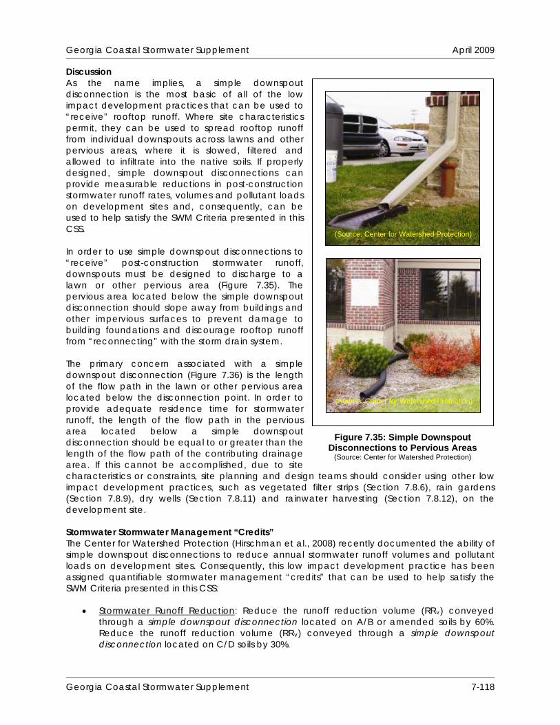
Georgia Coastal Stormwater Supplement April 2009
Discussion As the name implies, a simple downspout disconnection is the most basic of all of the low impact development practices that can be used to “receive” rooftop runoff. Where site characteristics permit, they can be used to spread rooftop runoff from individual downspouts across lawns and other pervious areas, where it is slowed, filtered and allowed to infiltrate into the native soils. If properly designed, simple downspout disconnections can provide measurable reductions in post-construction stormwater runoff rates, volumes and pollutant loads on development sites and, consequently, can be used to help satisfy the SWM Criteria presented in this CSS. In order to use simple downspout disconnections to “receive” post-construction stormwater runoff, downspouts must be designed to discharge to a lawn or other pervious area (Figure 7.35). The pervious area located below the simple downspout disconnection should slope away from buildings and other impervious surfaces to prevent damage to building foundations and discourage rooftop runoff from “reconnecting” with the storm drain system. The primary concern associated with a simple downspout disconnection (Figure 7.36) is the length of the flow path in the lawn or other pervious area located below the disconnection point. In order to provide adequate residence time for stormwater runoff, the length of the flow path in the pervious area located below a simple downspout disconnection should be equal to or greater than the length of the flow path of the contributing drainage area. If this cannot be accomplished, due to site characteristics or constraints, site planning and design teams should consider using other low impact development practices, such as vegetated filter strips (Section 7.8.6), rain gardens (Section 7.8.9), dry wells (Section 7.8.11) and rainwater harvesting (Section 7.8.12), on the development site.
(Source: Center for Watershed Protection)
(Source: Center for Watershed Protection)
Figure 7.35: Simple Downspout Disconnections to Pervious Areas
(Source: Center for Watershed Protection)
Stormwater Stormwater Management “Credits” The Center for Watershed Protection (Hirschman et al., 2008) recently documented the ability of simple downspout disconnections to reduce annual stormwater runoff volumes and pollutant loads on development sites. Consequently, this low impact development practice has been assigned quantifiable stormwater management “credits” that can be used to help satisfy the SWM Criteria presented in this CSS:
Stormwater Runoff Reduction: Reduce the runoff reduction volume (RRv) conveyed through a simple downspout disconnection located on A/B or amended soils by 60%. Reduce the runoff reduction volume (RRv) conveyed through a simple downspout disconnection located on C/D soils by 30%.
Georgia Coastal Stormwater Supplement 7-118

Georgia Coastal Stormwater Supplement April 2009
Figure 7.36: Simple Downspout Disconnection (Source: Maryland Department of the Environment, 2000)
Water Quality Protection: Reduce the runoff reduction volume (RRv) conveyed through a
simple downspout disconnection located on A/B or amended soils by 60%. Reduce the runoff reduction volume (RRv) conveyed through a simple downspout disconnection located on C/D soils by 30%.
Aquatic Resource Protection: Proportionally adjust the post-development runoff curve
number (CN) to account for the runoff reduction provided by a simple downspout disconnection when calculating the aquatic resource protection volume (ARPv) on a development site.
Overbank Flood Protection: Proportionally adjust the post-development runoff curve
number (CN) to account for the runoff reduction provided by a simple downspout disconnection when calculating the overbank peak discharge (Qp25) on a development site.
Extreme Flood Protection: Proportionally adjust the post-development runoff curve
number (CN) to account for the runoff reduction provided by a simple downspout disconnection when calculating the extreme peak discharge (Qp100) on a development site.
In order to “receive” stormwater runoff and be eligible for these “credits,” it is recommended that simple downspout disconnections satisfy the planning and design criteria outlined below. Overall Feasibility The criteria listed in Table 7.23 should be evaluated to determine whether or not a simple downspout disconnection is appropriate for use on a development site.
Georgia Coastal Stormwater Supplement 7-119

Georgia Coastal Stormwater Supplement April 2009
Table 7.23: Factors to Consider When Evaluating the Overall Feasibility of Using a Simple Downspout Disconnection on a Development Site
Site Characteristic Criteria
Drainage Area The size of the contributing drainage area should be 2,500 square feet or less. The length of the flow path in the contributing drainage area should be 75 feet or less.
Area Required
The length of flow path in the pervious area below a simple downspout disconnection should be at least 15 feet long and equal to or greater than the length of the flow path in its contributing drainage area.
Slope
Although simple downspout disconnections may be used on development sites with slopes of between 0.5% and 6%, it is recommended that they be designed with slopes of between 1% and 5% to help ensure adequate drainage.
Minimum Head N/A Minimum Depth to Water Table No restrictions
Soils No restrictions, although simple downspout disconnections located on permeable soils (i.e., hydrologic soil group A or B soils) provide greater stormwater management benefits.
Feasibility in Coastal Georgia Several site characteristics commonly encountered in coastal Georgia may present challenges to site planning and design teams that are interested in using simple downspout disconnections to “receive” post-construction stormwater runoff on a development site. Table 7.24 identifies these common site characteristics and describes how they influence the use of simple downspout disconnections on development sites. The table also provides site planning and design teams with some ideas about how they can work around these potential constraints.
Table 7.24: Challenges Associated with Using Simple Downspout Disconnections in Coastal Georgia
Site Characteristic How it Influences the Use of Downspout Disconnections Potential Solutions
Poorly drained soils, such as hydrologic soil group C and D soils
Reduces the ability of simple downspout disconnections to reduce stormwater runoff rates, volumes and pollutant loads.
Use soil restoration (Section 7.8.1) to improve soil porosity and the ability of simple downspout disconnections to reduce stormwater runoff rates, volumes and pollutant loads.
Use additional downspout disconnection practices, such as rain gardens (Section 7.8.9), dry wells (Section 7.8.11) and rainwater harvesting (Section 7.8.12) to supplement the stormwater management benefits provided by simple downspout disconnections.
Georgia Coastal Stormwater Supplement 7-120

Georgia Coastal Stormwater Supplement April 2009
Table 7.24: Challenges Associated with Using Simple Downspout Disconnections in Coastal Georgia
How it Influences the Use Site Characteristic Potential Solutions of Downspout Disconnections Well drained
soils, such as hydrologic soil group A and B soils
Enhances the ability of simple downspout disconnections to reduce stormwater runoff rates, volumes and pollutant loads, but may allow stormwater pollutants to reach groundwater aquifers with greater ease.
Rooftop runoff is relatively clean, so this should not prevent the use of simple downspout disconnections, even at stormwater hotspots and in areas known to provide groundwater recharge to water supply aquifers. However, rooftop runoff should not be allowed to comingle with runoff from other impervious surfaces in these areas if it will be “received” by a simple downspout disconnection.
Flat terrain May be difficult to provide adequate drainage and may cause stormwater runoff to pond in the pervious area located below a simple downspout disconnection.
Design the pervious area located below the simple downspout disconnection with a slope of at least 0.5% to help ensure adequate drainage.
Where soils are well drained, use rain gardens (Section 7.8.9), non-underdrained bioretention areas (Section 7.8.13) and infiltration practices (Section 7.8.14), to reduce stormwater runoff rates, volumes and pollutant loads and prevent ponding in these areas.
Where soils are poorly drained, use rainwater harvesting (Section 7.8.12), small stormwater wetlands (i.e., pocket wetlands) (Section 8.6.2) or wet swales (Section 8.6.6), instead of simple downspout disconnection to intercept and treat stormwater runoff.
Shallow water table
May occasionally cause stormwater runoff to pond in the pervious area located below a simple downspout disconnection.
Use rainwater harvesting (Section 7.8.9), small stormwater wetlands (i.e., pocket wetlands) (Section 8.6.2) or wet swales (Section 8.6.6), instead of downspout disconnection to intercept and treat stormwater runoff in these areas.
Georgia Coastal Stormwater Supplement 7-121
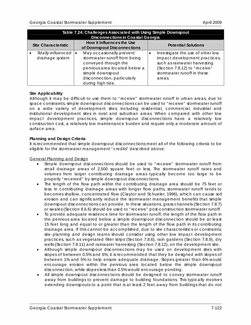
Georgia Coastal Stormwater Supplement April 2009
Table 7.24: Challenges Associated with Using Simple Downspout Disconnections in Coastal Georgia
How it Influences the Use Site Characteristic Potential Solutions of Downspout Disconnections Tidally-influenced
drainage system May occasionally prevent
stormwater runoff from being conveyed through the pervious area located below a simple downspout disconnection, particularly during high tide.
Investigate the use of other low impact development practices, such as rainwater harvesting (Section 7.8.12) to “receive” stormwater runoff in these areas.
Site Applicability Although it may be difficult to use them to “receive” stormwater runoff in urban areas, due to space constraints, simple downspout disconnections can be used to “receive” stormwater runoff on a wide variety of development sites, including residential, commercial, industrial and institutional development sites in rural and suburban areas. When compared with other low impact development practices, simple downspout disconnections have a relatively low construction cost, a relatively low maintenance burden and require only a moderate amount of surface area. Planning and Design Criteria It is recommended that simple downspout disconnections meet all of the following criteria to be eligible for the stormwater management “credits” described above:
General Planning and Design
Simple downspout disconnections should be used to “receive” stormwater runoff from small drainage areas of 2,500 square feet or less. The stormwater runoff rates and volumes from larger contributing drainage areas typically become too large to be properly “received” by simple downspout disconnections.
The length of the flow path within the contributing drainage area should be 75 feet or less. In contributing drainage areas with longer flow paths, stormwater runoff tends to becomes shallow, concentrated flow (Claytor and Schueler, 1996), which can cause soil erosion and can significantly reduce the stormwater management benefits that simple downspout disconnections can provide. In these situations, grass channels (Section 7.8.7) or swales (Section 8.6.6) should be used to “receive” post-construction stormwater runoff.
To provide adequate residence time for stormwater runoff, the length of the flow path in the pervious area located below a simple downspout disconnection should be at least 15 feet long and equal to or greater than the length of the flow path in its contributing drainage area. If this cannot be accomplished, due to site characteristics or constraints, site planning and design teams should consider using other low impact development practices, such as vegetated filter strips (Section 7.8.6), rain gardens (Section 7.8.9), dry wells (Section 7.8.11) and rainwater harvesting (Section 7.8.12), on the development site.
Although simple downspout disconnections may be used on development sites with slopes of between 0.5% and 6%, it is recommended that they be designed with slopes of between 1% and 5% to help ensure adequate drainage. Slopes greater than 6% would encourage erosion within the pervious area located below the simple downspout disconnection, while slopes less than 0.5% would encourage ponding.
All simple downspout disconnections should be designed to convey stormwater runoff away from buildings to prevent damage to building foundations. This typically involves extending downspouts to a point that is at least 2 feet away from buildings that do not
Georgia Coastal Stormwater Supplement 7-122

Georgia Coastal Stormwater Supplement April 2009
have basements or to a point that is at least 6 feet away from buildings that do have basements.
All simple downspout disconnections should be located at least 10 feet away from all impervious surfaces of equal or lower elevation to discourage rooftop runoff from “reconnecting” with the storm drain system.
Landscaping
Vegetation commonly planted in the pervious areas located below simple downspout disconnections includes turf, shrubs, trees and other herbaceous vegetation. Although managed turf is most commonly used, site planning and design teams are encouraged to use trees, shrubs and/or other native vegetation to help establish mature native plant communities in the pervious areas located below simple downspout disconnections.
Methods used to establish vegetative cover within the pervious area located below a simple downspout disconnection should achieve at least 75 percent vegetative cover one year after installation.
To help prevent soil erosion and sediment loss, landscaping should be provided immediately after the simple downspout disconnection has been completed. Temporary irrigation may be needed to quickly establish vegetative cover within the pervious areas located below simple downspout disconnections.
Construction Considerations To help ensure that simple downspout disconnections are properly installed on a development site, site planning and design teams should consider the following recommendations:
Simple erosion and sediment control measures, such as temporary seeding and erosion control mats, should be used within the pervious areas located below simple downspout disconnections.
To help prevent soil compaction, heavy vehicular and foot traffic should be kept out of the pervious areas located below simple downspout disconnections during and immediately after construction.
Construction contracts should contain a replacement warranty that covers at least three growing seasons to help ensure adequate growth and survival of the vegetation planted within the pervious area located below a simple downspout disconnection.
Maintenance Requirements Simple downspout disconnections typically require very little long-term maintenance, but a legally binding inspection and maintenance agreement and plan should be created to help ensure that they are properly maintained after construction is complete. Table 7.25 provides a list of the maintenance activities typically associated with simple downspout disconnections.
Table 7.25: Routine Maintenance Activities Typically Associated with Simple Downspout Disconnections
Activity Schedule
Pervious areas located below simple downspout disconnections should be watered to promote plant growth and survival.
Inspect the pervious areas located below simple downspout disconnections following rainfall events. Plant replacement vegetation in any eroded areas.
As Needed (Following Construction)
Georgia Coastal Stormwater Supplement 7-123
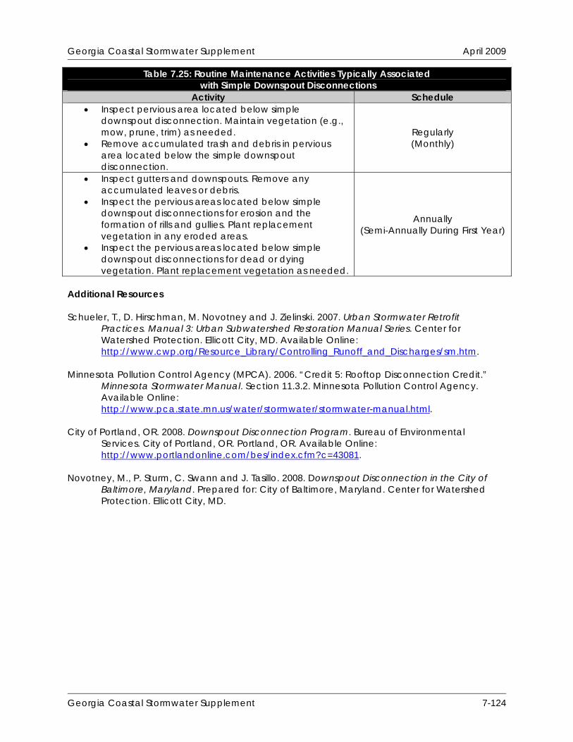
Georgia Coastal Stormwater Supplement April 2009
Table 7.25: Routine Maintenance Activities Typically Associated with Simple Downspout Disconnections
Activity Schedule Inspect pervious area located below simple
downspout disconnection. Maintain vegetation (e.g., mow, prune, trim) as needed.
Remove accumulated trash and debris in pervious area located below the simple downspout disconnection.
Regularly (Monthly)
Inspect gutters and downspouts. Remove any accumulated leaves or debris.
Inspect the pervious areas located below simple downspout disconnections for erosion and the formation of rills and gullies. Plant replacement vegetation in any eroded areas.
Inspect the pervious areas located below simple downspout disconnections for dead or dying vegetation. Plant replacement vegetation as needed.
Annually (Semi-Annually During First Year)
Additional Resources Schueler, T., D. Hirschman, M. Novotney and J. Zielinski. 2007. Urban Stormwater Retrofit
Practices. Manual 3: Urban Subwatershed Restoration Manual Series. Center for Watershed Protection. Ellicott City, MD. Available Online: http://www.cwp.org/Resource_Library/Controlling_Runoff_and_Discharges/sm.htm.
Minnesota Pollution Control Agency (MPCA). 2006. “Credit 5: Rooftop Disconnection Credit.”
Minnesota Stormwater Manual. Section 11.3.2. Minnesota Pollution Control Agency. Available Online: http://www.pca.state.mn.us/water/stormwater/stormwater-manual.html.
City of Portland, OR. 2008. Downspout Disconnection Program. Bureau of Environmental
Services. City of Portland, OR. Portland, OR. Available Online: http://www.portlandonline.com/bes/index.cfm?c=43081.
Novotney, M., P. Sturm, C. Swann and J. Tasillo. 2008. Downspout Disconnection in the City of
Baltimore, Maryland. Prepared for: City of Baltimore, Maryland. Center for Watershed Protection. Ellicott City, MD.
Georgia Coastal Stormwater Supplement 7-124
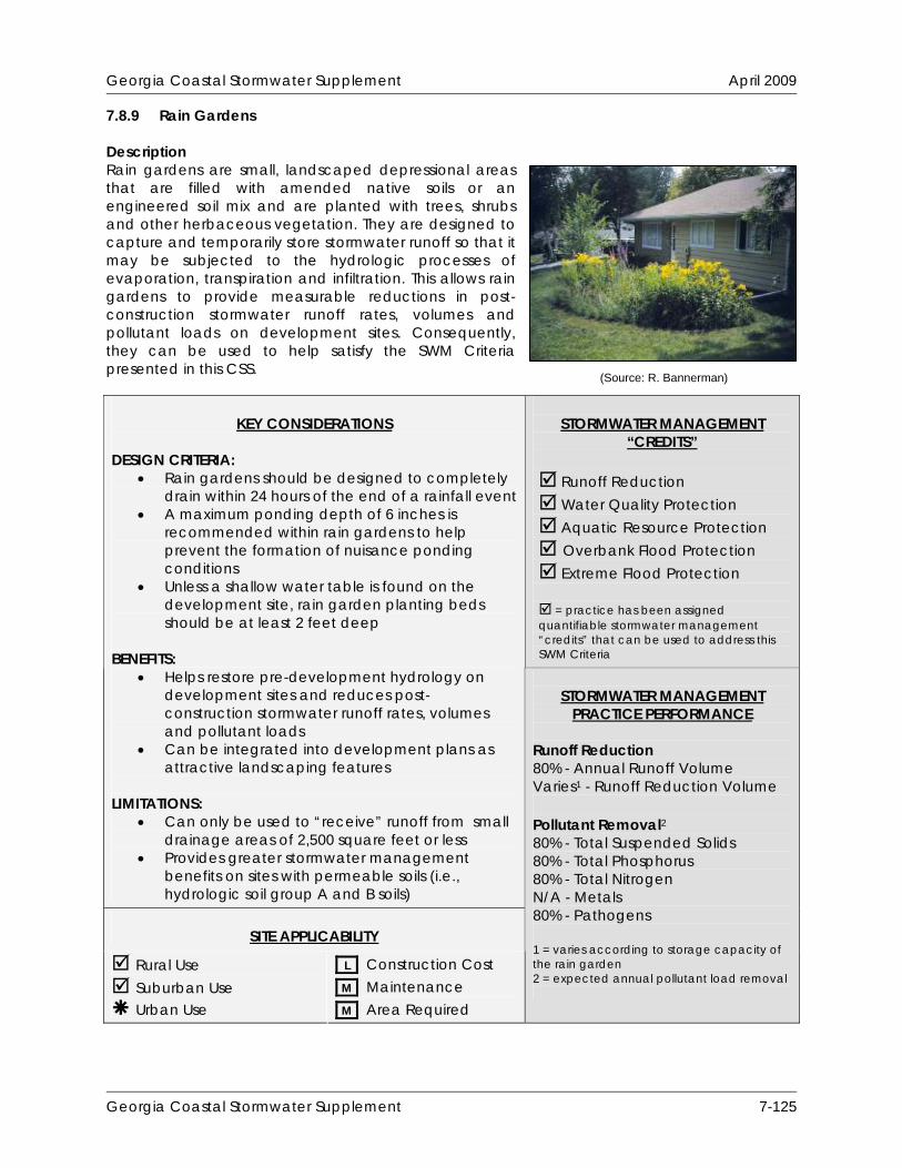
Georgia Coastal Stormwater Supplement April 2009
7.8.9 Rain Gardens Description Rain gardens are small, landscaped depressional areas that are filled with amended native soils or an engineered soil mix and are planted with trees, shrubs and other herbaceous vegetation. They are designed to capture and temporarily store stormwater runoff so that it may be subjected to the hydrologic processes of evaporation, transpiration and infiltration. This allows rain gardens to provide measurable reductions in post-construction stormwater runoff rates, volumes and pollutant loads on development sites. Consequently, they can be used to help satisfy the SWM Criteria presented in this CSS.
STORMWATER MANAGEMENT
“CREDITS”
Runoff Reduction Water Quality Protection Aquatic Resource Protection Overbank Flood Protection Extreme Flood Protection = practice has been assigned quantifiable stormwater management “credits” that can be used to address this SWM Criteria
KEY CONSIDERATIONS
DESIGN CRITERIA:
Rain gardens should be designed to completely drain within 24 hours of the end of a rainfall event
A maximum ponding depth of 6 inches is recommended within rain gardens to help prevent the formation of nuisance ponding conditions
Unless a shallow water table is found on the development site, rain garden planting beds should be at least 2 feet deep
BENEFITS:
Helps restore pre-development hydrology on development sites and reduces post-construction stormwater runoff rates, volumes and pollutant loads
Can be integrated into development plans as attractive landscaping features
LIMITATIONS:
Can only be used to “receive” runoff from small drainage areas of 2,500 square feet or less
Provides greater stormwater management benefits on sites with permeable soils (i.e., hydrologic soil group A and B soils)
SITE APPLICABILITY
Rural Use Suburban Use Urban Use
L Construction Cost M Maintenance M Area Required
STORMWATER MANAGEMENT
PRACTICE PERFORMANCE Runoff Reduction 80% - Annual Runoff Volume Varies1 - Runoff Reduction Volume Pollutant Removal2 80% - Total Suspended Solids 80% - Total Phosphorus 80% - Total Nitrogen N/A - Metals 80% - Pathogens 1 = varies according to storage capacity of the rain garden 2 = expected annual pollutant load removal
(Source: R. Bannerman)
Georgia Coastal Stormwater Supplement 7-125

Georgia Coastal Stormwater Supplement April 2009
Discussion Rain gardens are small, landscaped depressional areas that are filled with amended native soils or an engineered soil mix and are planted with trees, shrubs and other herbaceous vegetation (Figure 7.37). They are designed to capture and temporarily store stormwater runoff so that it may be subjected to the hydrologic processes of evaporation, transpiration and infiltration. This allows them to provide measurable reductions in post-construction stormwater runoff rates, volumes and pollutant loads on development sites.
The primary concern associated with the design of a rain garden is its storage capacity, which directly influences its ability to reduce stormwater runoff rates, volumes and pollutant loads. Site planning and design teams should strive to design rain gardens that can accommodate the stormwater runoff volume generated by the target runoff reduction rainfall event (e.g., 85th percentile rainfall event). If this cannot be accomplished, due to site characteristics or constraints, site planning and design teams should consider using rain gardens in combination with other runoff reducing low impact development practices, such as dry wells (Section 7.8.11) and rainwater harvesting (Section 7.8.12), to provide more substantial reductions in stormwater runoff rates, volumes and pollutant loads. Stormwater Management “Credits” The Center for Watershed Protection (Hirschman et al., 2008) recently documented the ability of rain gardens to reduce annual stormwater runoff volumes and pollutant loads on development
Figure 7.37: Various Rain Gardens
(Source: http://www.raingardens.org) (Source: Center for Watershed Protection)
(Source: http://www.ci.eagan.mn.us) (Source: Atlanta Regional Commission, 2001)
Georgia Coastal Stormwater Supplement 7-126
Georgia Coastal Stormwater Supplement April 2009
sites. Consequently, this low impact development practice has been assigned quantifiable stormwater management “credits” that can be used to help satisfy the SWM Criteria presented in this CSS:
Stormwater Runoff Reduction: Subtract 100% of the storage volume provided by a rain garden from the runoff reduction volume (RRv) conveyed through the rain garden.
Water Quality Protection: Subtract 100% of the storage volume provided by a rain
garden from the runoff reduction volume (RRv) conveyed through the rain garden.
Aquatic Resource Protection: Proportionally adjust the post-development runoff curve number (CN) to account for the runoff reduction provided by a rain garden when calculating the aquatic resource protection volume (ARPv) on a development site.
Overbank Flood Protection: Proportionally adjust the post-development runoff curve
number (CN) to account for the runoff reduction provided by a rain garden when calculating the overbank peak discharge (Qp25) on a development site.
Extreme Flood Protection: Proportionally adjust the post-development runoff curve
number (CN) to account for the runoff reduction provided by a rain garden when calculating the extreme peak discharge (Qp100) on a development site.
The storage volume provided by a rain garden can be determined using the following equation:
Storage Volume = Surface Area x [Ponding Depth + (Depth of Planting Bed x Void Ratio)] A void ratio (i.e., void space/total volume) of 0.32 should be used in all storage volume calculations, unless more specific planting bed void ratio data are available. In order to “receive” stormwater runoff and be eligible for these “credits,” it is recommended that rain gardens satisfy the planning and design criteria outlined below. Overall Feasibility The criteria listed in Table 7.26 should be evaluated to determine whether or not a rain garden is appropriate for use on a development site.
Table 7.26: Factors to Consider When Evaluating the Overall Feasibility of Using a Rain Garden on a Development Site
Site Characteristic Criteria
Drainage Area
The size of the contributing drainage area should be 2,500 square feet or less. The length of flow path in the contributing drainage area should be 150 feet or less in pervious drainage areas and 75 feet or less in impervious drainage areas. Bioretention areas (Section 7.8.13) should be used to “receive” stormwater runoff from larger contributing drainage areas or contributing drainage areas with longer flow paths.
Area Required
Rain garden surface area requirements vary according to the size of the contributing drainage area and the infiltration rate of the soils on which the rain garden will be located. In general, rain gardens require about 10-20% of the size of their contributing drainage areas.
Georgia Coastal Stormwater Supplement 7-127

Georgia Coastal Stormwater Supplement April 2009
Table 7.26: Factors to Consider When Evaluating the Overall Feasibility of Using a Rain Garden on a Development Site
Site Characteristic Criteria
Slope
Although rain gardens may be used on development sites with slopes of up to 6%, they should be designed with slopes that are as close to flat as possible to help ensure that stormwater runoff is evenly distributed over the planting bed.
Minimum Head
Rain gardens may be designed with a maximum ponding depth of 12 inches, although a ponding depth of 6 inches is recommended to help prevent the formation of nuisance ponding conditions. Unless a shallow water table is found on the development site, all rain garden planting beds should be at least 24 inches deep.
Minimum Depth to Water Table 2 feet
Soils
Rain gardens should be designed to completely drain within 24 hours of the end of a rainfall event. Consequently, rain gardens generally should not be used on development sites that have soils with infiltration rates of less than 0.50 inches per hour (i.e., hydrologic soil group C and D soils). Underdrained bioretention areas (Section 7.8.13) may be used to “receive” stormwater runoff on development sites that have soils with infiltration rates of less than 0.50 inches per hour.
Feasibility in Coastal Georgia Several site characteristics commonly encountered in coastal Georgia may present challenges to site planning and design teams that are interested in using rain gardens to “receive” post-construction stormwater runoff on a development site. Table 7.27 identifies these common site characteristics and describes how they influence the use of rain gardens on development sites. The table also provides site planning and design teams with some ideas about how they can work around these potential constraints.
Table 7.27: Challenges Associated with Using Rain Gardens in Coastal Georgia
Site Characteristic How it Influences the Use of Rain Gardens Potential Solutions
Poorly drained soils, such as hydrologic soil group C and D soils
Reduces the ability of rain gardens to reduce stormwater runoff rates, volumes and pollutant loads.
Use an engineered soil mix instead of amended native soils to create rain garden planting beds in these areas.
Use additional downspout disconnection practices, such as rainwater harvesting (Section 7.8.12) to supplement the stormwater management benefits provided by rain gardens in these areas.
Use rainwater harvesting (Section 7.8.9), small stormwater wetlands (i.e., pocket wetlands) (Section 8.6.2) or wet swales (Section 8.6.6), instead of rain gardens to intercept and treat stormwater runoff in these areas.
Georgia Coastal Stormwater Supplement 7-128
Georgia Coastal Stormwater Supplement April 2009
Table 7.27: Challenges Associated with Using Rain Gardens in Coastal Georgia How it Influences the Use Site Characteristic Potential Solutions of Rain Gardens
Well drained soils, such as hydrologic soil group A and B soils
Enhances the ability of rain gardens to reduce stormwater runoff rates, volumes and pollutant loads, but may allow stormwater pollutants to reach groundwater aquifers with greater ease.
Rooftop runoff is relatively clean, so this should not prevent the use of rain gardens, even at stormwater hotspots and in areas known to provide groundwater recharge to water supply aquifers. However, rooftop runoff should not be allowed to comingle with runoff from other impervious surfaces in these areas if it will be “received” by a rain garden.
Use bioretention areas (Section 7.8.13) and dry swales (Section 7.8.15) with liners and underdrains to intercept and treat non rooftop runoff at stormwater hotspots and in areas known to provide groundwater recharge to water supply aquifers.
Flat terrain May be difficult to provide adequate drainage and may cause stormwater runoff to pond in the rain garden for extended periods of time.
Ensure that the underlying native soils will allow the rain garden to drain completely within 24 hours of the end of a rainfall event to prevent the formation of nuisance ponding conditions.
Shallow water table
May be difficult to provide 2 feet of clearance between the bottom of the rain garden and the top of the water table.
May occasionally cause stormwater runoff to pond in the rain garden.
Ensure that the distance from the bottom of the rain garden to the top of the water table is at least 2 feet.
Reduce the depth of the planting bed to 18 inches.
Use rainwater harvesting (Section 7.8.12), small stormwater wetlands (i.e., pocket wetlands) (Section 8.6.2) or wet swales (Section 8.6.6), instead of rain gardens to intercept and treat stormwater runoff in these areas.
Tidally-influenced drainage system
May occasionally prevent stormwater runoff from being conveyed through a rain garden, particularly during high tide.
Investigate the use of other low impact development practices, such as rainwater harvesting (Section 7.8.12) to “receive” stormwater runoff in these areas.
Georgia Coastal Stormwater Supplement 7-129
Georgia Coastal Stormwater Supplement April 2009
Site Applicability Although it may be difficult to use them to “receive” stormwater runoff in urban areas, due to space constraints, rain gardens can be used to “receive” stormwater management on a wide variety of development sites, including residential, commercial and institutional development sites in rural and suburban areas. Although they are particularly well suited to “receive” rooftop runoff, they can also be used to “receive” stormwater runoff from other small drainage areas, such as local streets and roadways, driveways, small parking areas and disturbed pervious areas (e.g., lawns, parks, community open spaces). When compared with other low impact development practices, rain gardens have a relatively low construction cost, a moderate maintenance burden and require only a moderate amount of surface area. Planning and Design Criteria It is recommended that rain gardens meet all of the following criteria to be eligible for the stormwater management “credits” described above: General Planning and Design
Rain gardens should be used to “receive” stormwater runoff from small drainage areas of 2,500 square feet or less. The stormwater runoff rates and volumes from larger contributing drainage areas typically become too large to be properly “received” by rain gardens.
The length of the flow path within the contributing drainage area should be 150 feet or less for pervious drainage areas and 75 feet or less for impervious drainage areas. In contributing drainage areas with longer flow paths, stormwater runoff tends to becomes shallow, concentrated flow (Claytor and Schueler, 1996), which can cause soil erosion and can significantly reduce the stormwater management benefits that rain gardens can provide. In these situations, bioretention areas (Section 7.8.13) should be used to “receive” post-construction stormwater runoff.
Although rain gardens may be installed on development sites with slopes of up to 6%, they should be designed with slopes that are as close to flat as possible to help ensure that stormwater runoff is evenly distributed over the planting bed.
Rain gardens should be designed to provide enough storage for the stormwater runoff volume generated by the target runoff reduction rainfall event (e.g., 85th percentile rainfall event). Since they are essentially non-underdrained bioretention areas, the required dimensions of a rain garden can be determined using the design procedures provided in Section 8.6.3 of this CSS.
Rain gardens should be designed to completely drain within 24 hours of the end of a rainfall event. Where site characteristics allow, it is preferable to design rain gardens to drain within 12 hours of the end of a rainfall event to help prevent the formation of nuisance ponding conditions.
Rain gardens may be designed with a maximum ponding depth of 12 inches, although a ponding depth of 6 inches is recommended to help prevent the formation of nuisance ponding conditions.
Unless a shallow water table is found on the development site, all rain garden planting beds should be at least 24 inches deep. If a shallow water table is found on the development site, the depth of the planting bed may be reduced to 18 inches.
The soils used within rain garden planting beds may consist of either amended native soils or an engineered soil mix, but should meet the following specifications:
o Texture: Sandy loam or loamy sand. o Sand Content: Soils should contain 85%-88% clean, washed sand. o Topsoil Content: Soils should contain 8%-12% topsoil. o Organic Matter Content: Soils should contain 3%-5% organic matter.
Georgia Coastal Stormwater Supplement 7-130

Georgia Coastal Stormwater Supplement April 2009
o Infiltration Rate: Soils should have an infiltration rate of at least 0.25 inches per hour (in/hr), although an infiltration rate of between 1 and 2 in/hr is preferred.
o Phosphorus Index (P-Index): Soils should have a P-Index of less than 30. o Exchange Capacity (CEC): Soils should have a CEC that exceeds 10
milliequivalents (meq) per 100 grams of dry weight. o pH: Soils should have a pH of 6-8.
The organic matter used within a rain garden planting bed should be a well-aged compost that meets the specifications outlined in Section 7.8.1.
All rain gardens should be located at least 10 feet away from buildings to prevent damage to building foundations.
All rain gardens should be located at least 10 feet away from all impervious surfaces of equal or lower elevation to discourage rooftop runoff from “reconnecting” with the storm drain system.
Rain gardens should be designed with side slopes of 3:1 (H:V) or flatter. The depth from the bottom of a rain garden to the top of the water table should be at
least 2 feet to help prevent ponding and ensure proper operation of the rain garden. On development sites with high water tables, small stormwater wetlands (i.e., pocket wetlands) (Section 8.6.2) should be used to intercept and treat post-construction stormwater runoff.
If used to “receive” non rooftop runoff, rain gardens should be preceded by a pea gravel diaphragm or equivalent level spreader device (e.g., concrete sills, curb stops, curbs with “sawteeth” cut into them) to intercept stormwater runoff and distribute it evenly, as overland sheet flow, into the rain garden.
Consideration should be given to the stormwater runoff rates and volumes generated by larger storm events (e.g., 25-year, 24-hour storm event) to help ensure that these larger storm events are able to safely bypass the rain garden. An overflow system, such as a spillway with an invert set slightly above the elevation of maximum ponding depth within the rain garden, should be designed to convey the stormwater runoff generated by these larger storm events safely out of the rain garden.
Landscaping
A landscaping plan should be prepared for all rain gardens. The landscaping plan should be reviewed and approved by the local development review authority prior to construction.
Vegetation commonly planted in rain gardens includes native trees, shrubs and other herbaceous vegetation. When developing a landscaping plan, site planning and design teams should choose vegetation that will be able to stabilize soils and tolerate the stormwater runoff rates and volumes that will pass through the rain garden. Vegetation used in rain gardens should also be able to tolerate both wet and dry conditions. See Appendix F of Volume 2 of the Georgia Stormwater Management Manual (ARC, 2001) for a list of grasses and other plants that are appropriate for use in rain gardens in the state of Georgia.
A mulch layer, consisting of 2-4 inches of fine shredded hardwood mulch or shredded hardwood chips, should be included on the surface of the rain garden.
Methods used to establish vegetative cover within a rain garden should achieve at least 75 percent vegetative cover one year after installation.
To help prevent soil erosion and sediment loss, landscaping should be provided immediately after the rain garden has been installed. Temporary irrigation may be needed to quickly establish vegetative cover within a rain garden.
Georgia Coastal Stormwater Supplement 7-131
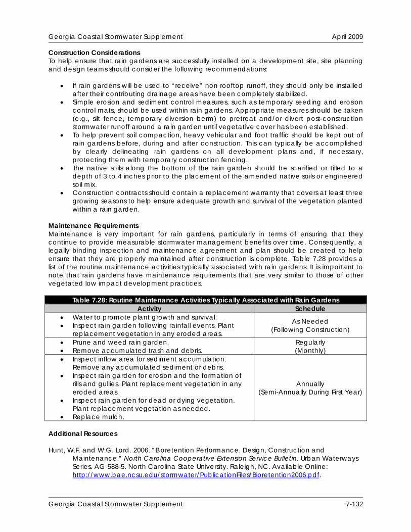
Georgia Coastal Stormwater Supplement April 2009
Construction Considerations To help ensure that rain gardens are successfully installed on a development site, site planning and design teams should consider the following recommendations:
If rain gardens will be used to “receive” non rooftop runoff, they should only be installed after their contributing drainage areas have been completely stabilized.
Simple erosion and sediment control measures, such as temporary seeding and erosion control mats, should be used within rain gardens. Appropriate measures should be taken (e.g., silt fence, temporary diversion berm) to pretreat and/or divert post-construction stormwater runoff around a rain garden until vegetative cover has been established.
To help prevent soil compaction, heavy vehicular and foot traffic should be kept out of rain gardens before, during and after construction. This can typically be accomplished by clearly delineating rain gardens on all development plans and, if necessary, protecting them with temporary construction fencing.
The native soils along the bottom of the rain garden should be scarified or tilled to a depth of 3 to 4 inches prior to the placement of the amended native soils or engineered soil mix.
Construction contracts should contain a replacement warranty that covers at least three growing seasons to help ensure adequate growth and survival of the vegetation planted within a rain garden.
Maintenance Requirements Maintenance is very important for rain gardens, particularly in terms of ensuring that they continue to provide measurable stormwater management benefits over time. Consequently, a legally binding inspection and maintenance agreement and plan should be created to help ensure that they are properly maintained after construction is complete. Table 7.28 provides a list of the routine maintenance activities typically associated with rain gardens. It is important to note that rain gardens have maintenance requirements that are very similar to those of other vegetated low impact development practices.
Table 7.28: Routine Maintenance Activities Typically Associated with Rain Gardens Activity Schedule
Water to promote plant growth and survival. Inspect rain garden following rainfall events. Plant
replacement vegetation in any eroded areas.
As Needed (Following Construction)
Prune and weed rain garden. Remove accumulated trash and debris.
Regularly (Monthly)
Inspect inflow area for sediment accumulation. Remove any accumulated sediment or debris.
Inspect rain garden for erosion and the formation of rills and gullies. Plant replacement vegetation in any eroded areas.
Inspect rain garden for dead or dying vegetation. Plant replacement vegetation as needed.
Replace mulch.
Annually (Semi-Annually During First Year)
Additional Resources Hunt, W.F. and W.G. Lord. 2006. “Bioretention Performance, Design, Construction and
Maintenance.” North Carolina Cooperative Extension Service Bulletin. Urban Waterways Series. AG-588-5. North Carolina State University. Raleigh, NC. Available Online: http://www.bae.ncsu.edu/stormwater/PublicationFiles/Bioretention2006.pdf.
Georgia Coastal Stormwater Supplement 7-132

Georgia Coastal Stormwater Supplement April 2009
Biohabitats, Inc. 2005. Bioretention Guidance. Prepared for: Lake County, OH. Stormwater Management Department. Available Online: http://www2.lakecountyohio.org/smd/Forms.htm.
Atlanta Regional Commission (ARC). 2001. “Bioretention Areas.” Georgia Stormwater
Management Manual. Volume 2. Technical Handbook. Section 3.2.3. Atlanta Regional Commission. Atlanta, GA. Available Online: http://www.georgia stormwater.com/.
Georgia Coastal Stormwater Supplement 7-133

Georgia Coastal Stormwater Supplement April 2009
THIS PAGE INTENTIONALLY LEFT BLANK
Georgia Coastal Stormwater Supplement 7-134
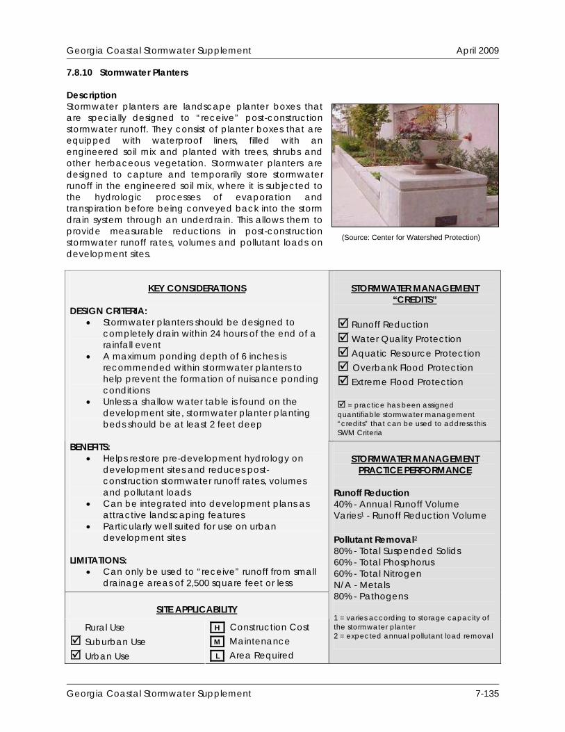
Georgia Coastal Stormwater Supplement April 2009
7.8.10 Stormwater Planters Description Stormwater planters are landscape planter boxes that are specially designed to “receive” post-construction stormwater runoff. They consist of planter boxes that are equipped with waterproof liners, filled with an engineered soil mix and planted with trees, shrubs and other herbaceous vegetation. Stormwater planters are designed to capture and temporarily store stormwater runoff in the engineered soil mix, where it is subjected to the hydrologic processes of evaporation and transpiration before being conveyed back into the storm drain system through an underdrain. This allows them to provide measurable reductions in post-construction stormwater runoff rates, volumes and pollutant loads on development sites.
(Source: Center for Watershed Protection)
STORMWATER MANAGEMENT “CREDITS”
Runoff Reduction Water Quality Protection Aquatic Resource Protection Overbank Flood Protection Extreme Flood Protection = practice has been assigned quantifiable stormwater management “credits” that can be used to address this SWM Criteria
KEY CONSIDERATIONS
DESIGN CRITERIA:
Stormwater planters should be designed to completely drain within 24 hours of the end of a rainfall event
A maximum ponding depth of 6 inches is recommended within stormwater planters to help prevent the formation of nuisance ponding conditions
Unless a shallow water table is found on the development site, stormwater planter planting beds should be at least 2 feet deep
BENEFITS:
Helps restore pre-development hydrology on development sites and reduces post-construction stormwater runoff rates, volumes and pollutant loads
Can be integrated into development plans as attractive landscaping features
Particularly well suited for use on urban development sites
LIMITATIONS:
Can only be used to “receive” runoff from small drainage areas of 2,500 square feet or less
SITE APPLICABILITY
Rural Use Suburban Use Urban Use
H Construction Cost M Maintenance L Area Required
STORMWATER MANAGEMENT
PRACTICE PERFORMANCE Runoff Reduction 40% - Annual Runoff Volume Varies1 - Runoff Reduction Volume Pollutant Removal2 80% - Total Suspended Solids 60% - Total Phosphorus 60% - Total Nitrogen N/A - Metals 80% - Pathogens 1 = varies according to storage capacity of the stormwater planter 2 = expected annual pollutant load removal
Georgia Coastal Stormwater Supplement 7-135
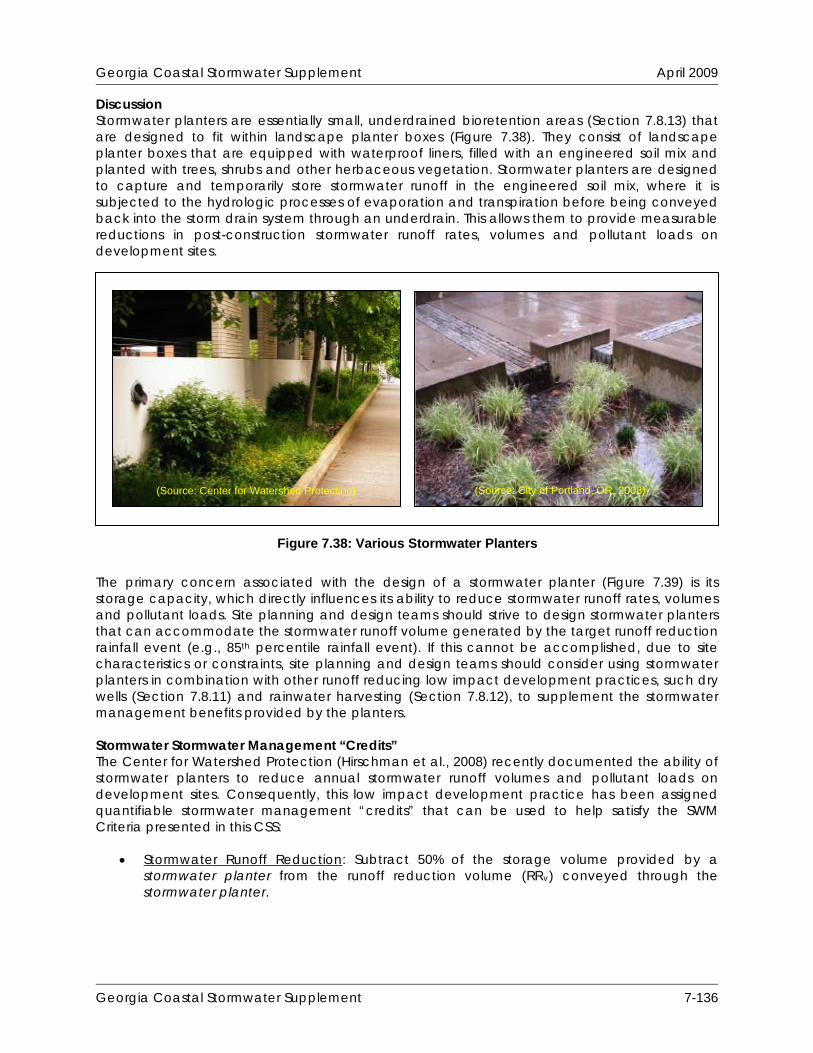
Georgia Coastal Stormwater Supplement April 2009
Discussion Stormwater planters are essentially small, underdrained bioretention areas (Section 7.8.13) that are designed to fit within landscape planter boxes (Figure 7.38). They consist of landscape planter boxes that are equipped with waterproof liners, filled with an engineered soil mix and planted with trees, shrubs and other herbaceous vegetation. Stormwater planters are designed to capture and temporarily store stormwater runoff in the engineered soil mix, where it is subjected to the hydrologic processes of evaporation and transpiration before being conveyed back into the storm drain system through an underdrain. This allows them to provide measurable reductions in post-construction stormwater runoff rates, volumes and pollutant loads on development sites.
(Source: City of Portland, OR, 2008) (Source: Center for Watershed Protection)
Figure 7.38: Various Stormwater Planters
The primary concern associated with the design of a stormwater planter (Figure 7.39) is its storage capacity, which directly influences its ability to reduce stormwater runoff rates, volumes and pollutant loads. Site planning and design teams should strive to design stormwater planters that can accommodate the stormwater runoff volume generated by the target runoff reduction rainfall event (e.g., 85th percentile rainfall event). If this cannot be accomplished, due to site characteristics or constraints, site planning and design teams should consider using stormwater planters in combination with other runoff reducing low impact development practices, such dry wells (Section 7.8.11) and rainwater harvesting (Section 7.8.12), to supplement the stormwater management benefits provided by the planters. Stormwater Stormwater Management “Credits” The Center for Watershed Protection (Hirschman et al., 2008) recently documented the ability of stormwater planters to reduce annual stormwater runoff volumes and pollutant loads on development sites. Consequently, this low impact development practice has been assigned quantifiable stormwater management “credits” that can be used to help satisfy the SWM Criteria presented in this CSS:
Stormwater Runoff Reduction: Subtract 50% of the storage volume provided by a stormwater planter from the runoff reduction volume (RRv) conveyed through the stormwater planter.
Georgia Coastal Stormwater Supplement 7-136
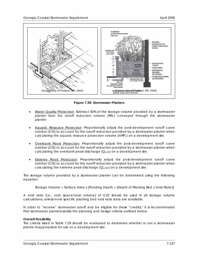
Georgia Coastal Stormwater Supplement April 2009
Water Quality Protection: Subtract 50% of the storage volume provided by a stormwater
planter from the runoff reduction volume (RRv) conveyed through the stormwater planter.
Aquatic Resource Protection: Proportionally adjust the post-development runoff curve
number (CN) to account for the runoff reduction provided by a stormwater planter when calculating the aquatic resource protection volume (ARPv) on a development site.
Overbank Flood Protection: Proportionally adjust the post-development runoff curve
number (CN) to account for the runoff reduction provided by a stormwater planter when calculating the overbank peak discharge (Qp25) on a development site.
Extreme Flood Protection: Proportionally adjust the post-development runoff curve
number (CN) to account for the runoff reduction provided by a stormwater planter when calculating the extreme peak discharge (Qp100) on a development site.
The storage volume provided by a stormwater planter can be determined using the following equation:
Storage Volume = Surface Area x [Ponding Depth + (Depth of Planting Bed x Void Ratio)] A void ratio (i.e., void space/total volume) of 0.32 should be used in all storage volume calculations, unless more specific planting bed void ratio data are available. In order to “receive” stormwater runoff and be eligible for these “credits,” it is recommended that stormwater planters satisfy the planning and design criteria outlined below. Overall Feasibility The criteria listed in Table 7.29 should be evaluated to determine whether or not a stormwater planter is appropriate for use on a development site.
Figure 7.39: Stormwater Planters
(Source: City of Portland, OR, 2004) (Source: City of Portland, OR, 2004)
Georgia Coastal Stormwater Supplement 7-137

Georgia Coastal Stormwater Supplement April 2009
Table 7.29: Factors to Consider When Evaluating the Overall Feasibility of Using a Stormwater Planter on a Development Site
Site Characteristic Criteria
Drainage Area
The size of the contributing drainage area should be 2,500 square feet or less. The length of flow path in contributing drainage areas should be 150 feet or less in pervious drainage areas and 75 feet or less in impervious drainage areas. Bioretention areas (Section 7.8.13) should be used to “receive” stormwater runoff from larger contributing drainage areas or contributing drainage areas with longer flow paths.
Area Required Stormwater planter surface area requirements vary according to the size of the contributing drainage area. In general, stormwater planters require about 5% of the size of their contributing drainage areas.
Slope
Although stormwater planters may be used on development sites with slopes of up to 6%, they should be designed with slopes that are as close to flat as possible to help ensure that stormwater runoff is evenly distributed over the planting bed.
Minimum Head
Stormwater planters may be designed with a maximum ponding depth of 12 inches, although a ponding depth of 6 inches is recommended to help prevent the formation of nuisance ponding conditions. Unless a shallow water table is found on the development site, all stormwater planter planting beds should be at least 24 inches deep.
Minimum Depth to Water Table
Unless a shallow water table is found on the development site, the distance from the bottom of a stormwater planter to the top of the water table should be at least 2 feet.
Soils Stormwater planters should be designed to completely drain within 24 hours of the end of a rainfall event.
Feasibility in Coastal Georgia Several site characteristics commonly encountered in coastal Georgia may present challenges to site planning and design teams that are interested in using stormwater planters to “receive” post-construction stormwater runoff on a development site. Table 7.30 identifies these common site characteristics and describes how they influence the use of stormwater planters on development sites. The table also provides site planning and design teams with some ideas about how they can work around these potential constraints.
Table 7.30: Challenges Associated with Using Stormwater Planters in Coastal Georgia
Site Characteristic How it Influences the Use of Stormwater Planters Potential Solutions
Poorly drained soils, such as hydrologic soil group C and D soils
Since they are equipped with waterproof liners and underdrains, the presence of poorly drained soils does not influence the use of stormwater planters on development sites.
Well drained soils, such as hydrologic soil group A and B soils
Since they are equipped with waterproof liners and underdrains, the presence of poorly drained soils does not influence the use of stormwater planters on development sites.
Georgia Coastal Stormwater Supplement 7-138
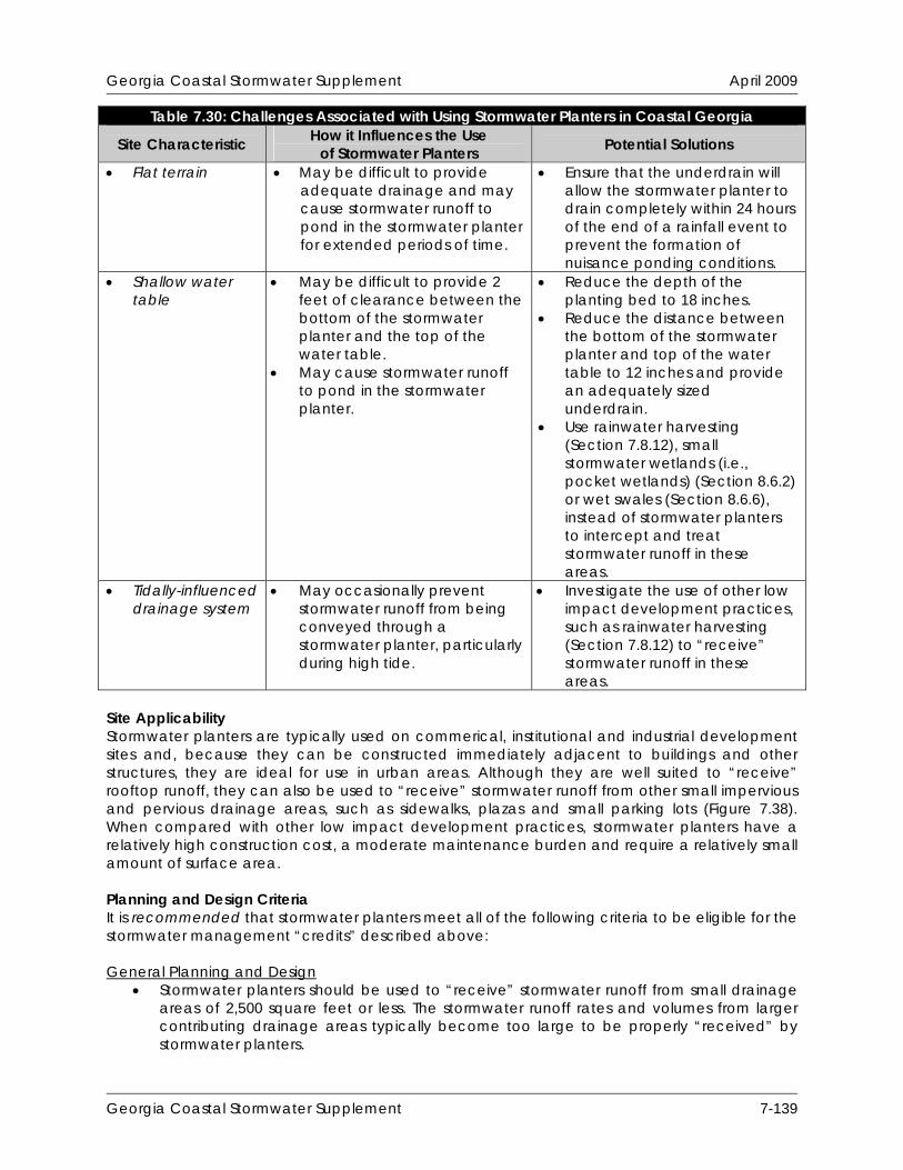
Georgia Coastal Stormwater Supplement April 2009
Table 7.30: Challenges Associated with Using Stormwater Planters in Coastal Georgia How it Influences the Use Site Characteristic Potential Solutions of Stormwater Planters
Flat terrain May be difficult to provide adequate drainage and may cause stormwater runoff to pond in the stormwater planter for extended periods of time.
Ensure that the underdrain will allow the stormwater planter to drain completely within 24 hours of the end of a rainfall event to prevent the formation of nuisance ponding conditions.
Shallow water table
May be difficult to provide 2 feet of clearance between the bottom of the stormwater planter and the top of the water table.
May cause stormwater runoff to pond in the stormwater planter.
Reduce the depth of the planting bed to 18 inches.
Reduce the distance between the bottom of the stormwater planter and top of the water table to 12 inches and provide an adequately sized underdrain.
Use rainwater harvesting (Section 7.8.12), small stormwater wetlands (i.e., pocket wetlands) (Section 8.6.2) or wet swales (Section 8.6.6), instead of stormwater planters to intercept and treat stormwater runoff in these areas.
Tidally-influenced drainage system
May occasionally prevent stormwater runoff from being conveyed through a stormwater planter, particularly during high tide.
Investigate the use of other low impact development practices, such as rainwater harvesting (Section 7.8.12) to “receive” stormwater runoff in these areas.
Site Applicability Stormwater planters are typically used on commerical, institutional and industrial development sites and, because they can be constructed immediately adjacent to buildings and other structures, they are ideal for use in urban areas. Although they are well suited to “receive” rooftop runoff, they can also be used to “receive” stormwater runoff from other small impervious and pervious drainage areas, such as sidewalks, plazas and small parking lots (Figure 7.38). When compared with other low impact development practices, stormwater planters have a relatively high construction cost, a moderate maintenance burden and require a relatively small amount of surface area. Planning and Design Criteria It is recommended that stormwater planters meet all of the following criteria to be eligible for the stormwater management “credits” described above: General Planning and Design
Stormwater planters should be used to “receive” stormwater runoff from small drainage areas of 2,500 square feet or less. The stormwater runoff rates and volumes from larger contributing drainage areas typically become too large to be properly “received” by stormwater planters.
Georgia Coastal Stormwater Supplement 7-139

Georgia Coastal Stormwater Supplement April 2009
The length of the flow path within the contributing drainage area should be 150 feet or less for pervious drainage areas and 75 feet or less for impervious drainage areas. In contributing drainage areas with longer flow paths, stormwater runoff tends to becomes shallow, concentrated flow (Claytor and Schueler, 1996), which can cause soil erosion and can significantly reduce the stormwater management benefits that stormwater planters can provide. In these situations, bioretention areas (Section 7.8.13) should be used to “receive” post-construction stormwater runoff.
Stormwater planters should be designed to provide enough storage for the stormwater runoff volume generated by the target runoff reduction rainfall event (e.g., 85th percentile rainfall event). Since they are essentially underdrained bioretention areas, the required dimensions of a stormwater planter can be determined using the design procedures provided in Section 8.6.3 of this CSS.
Stormwater planters should be designed to completely drain within 24 hours of the end of a rainfall event. Where site characteristics allow, it is preferable to design stormwater planters to drain within 12 hours of the end of a rainfall event to help prevent the formation of nuisance ponding conditions.
Stormwater planters may be designed with a maximum ponding depth of 12 inches, although a ponding depth of 6 inches is recommended to help prevent the formation of nuisance ponding conditions.
A minimum of 2 inches of freeboard should be provided between the elevation of the maximum ponding depth and the top of the planter box.
Unless a shallow water table is found on the development site, all stormwater planter planting beds should be at least 24 inches deep. If a shallow water table is found on the development site, the depth of the planting bed may be reduced to 18 inches.
The soils used within stormwater planter planting beds should be an engineered soil mix that meets the following specifications:
o Texture: Sandy loam or loamy sand. o Sand Content: Soils should contain 85%-88% clean, washed sand. o Topsoil Content: Soils should contain 8%-12% topsoil. o Organic Matter Content: Soils should contain 3%-5% organic matter. o Infiltration Rate: Soils should have an infiltration rate of at least 0.25 inches per
hour (in/hr), although an infiltration rate of between 1 and 2 in/hr is preferred. o Phosphorus Index (P-Index): Soils should have a P-Index of less than 30. o Exchange Capacity (CEC): Soils should have a CEC that exceeds 10
milliequivalents (meq) per 100 grams of dry weight. o pH: Soils should have a pH of 6-8.
The organic matter used within a stormwater planter planting bed should be a well-aged compost that meets the specifications outlined in Section 7.8.1.
A minimum width, measured from inside wall to inside wall, of 18 inches is recommended for all stormwater planters.
All stormwater planters should be equipped with a waterproof liner to prevent damage to building foundations and other adjacent impervious surfaces. Waterproof liners should be 30 mil (0.030 inch) polyvinylchloride (PVC) or equivalent.
Although stormwater planters may be used on development sites with slopes of up to 6%, they should be designed with slopes that are as close to flat as possible to help ensure that stormwater runoff is evenly distributed over the planting bed.
Stormwater planters should be constructed of stone, concrete, brick or other durable material. Chemically treated wood that can leach toxic chemicals and contaminate stormwater runoff should not be used to construct a stormwater planter.
Stormwater planters should be equipped with an underdrain consisting of a 4 inch perforated PVC (AASHTO M 252) pipe bedded in a 6 inch layer of clean, washed stone. The pipe should have 3/8 inch perforations, spaced 6 inches on center, and should have
Georgia Coastal Stormwater Supplement 7-140

Georgia Coastal Stormwater Supplement April 2009
a minimum slope of 0.5%. The clean, washed stone should be ASTM D448 size No. 57 stone (i.e., 1-1/2 to 1/2 inches in size) and should be separated from the planting bed by a layer of permeable filter fabric or a thin, 2 to 4 inch layer of choker stone (i.e., ASTM D 448 size No. 8, 3/8” to 1/8” or ASTM D 448 size No. 89, 3/8” to 1/16”). If permeable filter fabric is used, the filter fabric should be a non-woven geotextile with a permeability that is greater than or equal to the hydraulic conductivity of the overlying planting bed.
Unless a shallow water table is found on the development site, the distance from the bottom of a stormwater planter to the top of the water table should be at least 2 feet. If a shallow water table is found on the development site, the distance from the bottom of a stormwater planter to the top of the water table may be reduced to 12 inches.
If used to “receive” non rooftop runoff, stormwater planters should be preceded by a pea gravel diaphragm or equivalent level spreader device (e.g., concrete sills, curb stops, curbs with “sawteeth” cut into them) to intercept stormwater runoff and distribute it evenly, as overland sheet flow, across the stormwater planter.
Consideration should be given to the stormwater runoff rates and volumes generated by larger storm events (e.g., 25-year, 24-hour storm event) to help ensure that these larger storm events are able to safely bypass the stormwater planter. An overflow system, such as an overdrain with an invert set slightly above the elevation of maximum ponding depth, should be designed to convey the stormwater runoff generated by these larger storm events safely out of the stormwater planter.
Landscaping
A landscaping plan should be prepared for all stormwater planters. The landscaping plan should be reviewed and approved by the local development review authority prior to construction.
Vegetation commonly planted in stormwater planters includes native trees, shrubs and other herbaceous vegetation. When developing a landscaping plan, site planning and design teams should choose vegetation that will be able to stabilize soils and tolerate the stormwater runoff rates and volumes that will pass through the stormwater planter. Vegetation used in stormwater planters should also be able to tolerate both wet and dry conditions. See Appendix F of Volume 2 of the Georgia Stormwater Management Manual (ARC, 2001) for a list of grasses and other plants that are appropriate for use in stormwater planters in the state of Georgia.
A mulch layer, consisting of 2-4 inches of fine shredded hardwood mulch or shredded hardwood chips, should be included on the surface of the stormwater planter.
Methods used to establish vegetative cover within a stormwater planter should achieve at least 75 percent vegetative cover one year after installation.
To help prevent soil erosion and sediment loss, landscaping should be provided immediately after the stormwater planter has been installed. Temporary irrigation may be needed to quickly establish vegetative cover within a stormwater planter.
Construction Considerations To help ensure that stormwater planters are successfully installed on a development site, site planning and design teams should consider the following recommendations:
If stormwater planters will be used to “receive” non rooftop runoff, they should only be installed after their contributing drainage areas have been completely stabilized.
Simple erosion and sediment control measures, such as temporary seeding and erosion control mats, should be used within the stormwater planter. Appropriate measures should be taken (e.g., temporary diversion) to divert post-construction stormwater runoff around a stormwater planter until vegetative cover has been established.
Georgia Coastal Stormwater Supplement 7-141

Georgia Coastal Stormwater Supplement April 2009
To help prevent soil compaction, heavy vehicular and foot traffic should be kept out of stormwater planters during and after construction.
Construction contracts should contain a replacement warranty that covers at least three growing seasons to help ensure adequate growth and survival of the vegetation planted within a stormwater planter.
Maintenance Requirements Maintenance is very important for stormwater planters, particularly in terms of ensuring that they continue to provide measurable stormwater management benefits over time. Consequently, a legally binding inspection and maintenance agreement and plan should be created to help ensure that they are properly maintained after construction is complete. Table 7.31 provides a list of the routine maintenance activities typically associated with stormwater planters. It is important to note that rain gardens have maintenance requirements that are very similar to those of other vegetated low impact development practices.
Table 7.31: Routine Maintenance Activities Typically Associated with Stormwater Planters Activity Schedule
Water to promote plant growth and survival. Inspect stormwater planter following rainfall events.
Plant replacement vegetation in any eroded areas.
As Needed (Following Construction)
Prune and weed stormwater planter. Remove accumulated trash and debris.
Monthly (At a Minimum)
Inspect inflow and outflow areas for sediment accumulation. Remove any accumulated sediment or debris.
Inspect stormwater planter for erosion and the formation of rills and gullies. Plant replacement vegetation in any eroded areas.
Inspect stormwater planter for dead or dying vegetation. Plant replacement vegetation as needed.
Replace mulch.
Annually (Semi-Annually During First Year)
Additional Resources City of Portland, OR. 2008. “Planter.” Portland Stormwater Management Manual. Section 2.3.3.
City of Portland, OR. Bureau of Environmental Services. Available Online: http://www.portlandonline.com/bes/index.cfm?c=47952.
Atlanta Regional Commission (ARC). 2001. “Bioretention Areas.” Georgia Stormwater
Management Manual. Volume 2. Technical Handbook. Section 3.2.3. Atlanta Regional Commission. Atlanta, GA. Available Online: http://www.georgia stormwater.com/.
Georgia Coastal Stormwater Supplement 7-142
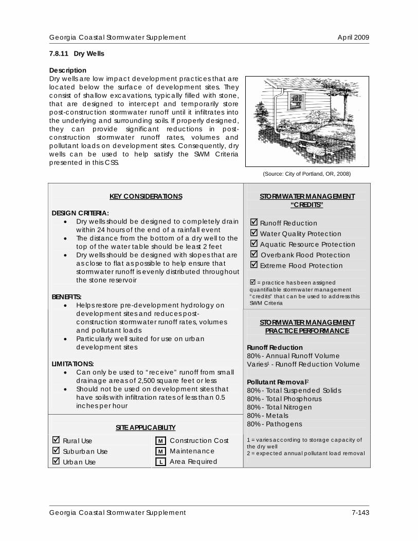
Georgia Coastal Stormwater Supplement April 2009
7.8.11 Dry Wells Description Dry wells are low impact development practices that are located below the surface of development sites. They consist of shallow excavations, typically filled with stone, that are designed to intercept and temporarily store post-construction stormwater runoff until it infiltrates into the underlying and surrounding soils. If properly designed, they can provide significant reductions in post-construction stormwater runoff rates, volumes and pollutant loads on development sites. Consequently, dry wells can be used to help satisfy the SWM Criteria presented in this CSS.
STORMWATER MANAGEMENT
“CREDITS”
Runoff Reduction Water Quality Protection Aquatic Resource Protection Overbank Flood Protection Extreme Flood Protection = practice has been assigned quantifiable stormwater management “credits” that can be used to address this SWM Criteria
KEY CONSIDERATIONS
DESIGN CRITERIA:
Dry wells should be designed to completely drain within 24 hours of the end of a rainfall event
The distance from the bottom of a dry well to the top of the water table should be least 2 feet
Dry wells should be designed with slopes that are as close to flat as possible to help ensure that stormwater runoff is evenly distributed throughout the stone reservoir
BENEFITS:
Helps restore pre-development hydrology on development sites and reduces post-construction stormwater runoff rates, volumes and pollutant loads
Particularly well suited for use on urban development sites
LIMITATIONS:
Can only be used to “receive” runoff from small drainage areas of 2,500 square feet or less
Should not be used on development sites that have soils with infiltration rates of less than 0.5 inches per hour
SITE APPLICABILITY
Rural Use Suburban Use Urban Use
M Construction Cost M Maintenance L Area Required
STORMWATER MANAGEMENT
PRACTICE PERFORMANCE Runoff Reduction 80% - Annual Runoff Volume Varies1 - Runoff Reduction Volume Pollutant Removal2 80% - Total Suspended Solids 80% - Total Phosphorus 80% - Total Nitrogen 80% - Metals 80% - Pathogens 1 = varies according to storage capacity of the dry well 2 = expected annual pollutant load removal
(Source: City of Portland, OR, 2008)
Georgia Coastal Stormwater Supplement 7-143
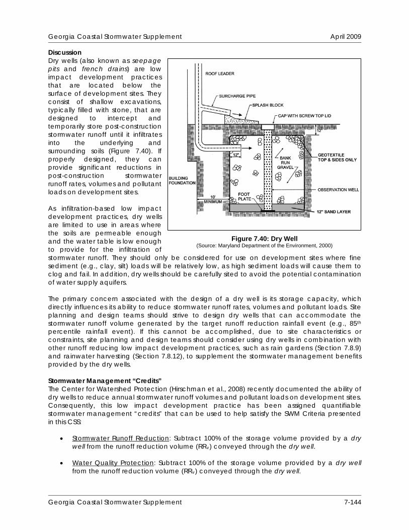
Georgia Coastal Stormwater Supplement April 2009
Discussion Dry wells (also known as seepage pits and french drains) are low impact development practices that are located below the surface of development sites. They consist of shallow excavations, typically filled with stone, that are designed to intercept and temporarily store post-construction stormwater runoff until it infiltrates into the underlying and surrounding soils (Figure 7.40). If properly designed, they can provide significant reductions in post-construction stormwater runoff rates, volumes and pollutant loads on development sites. As infiltration-based low impact development practices, dry wells are limited to use in areas where the soils are permeable enough and the water table is low enough to provide for the infiltration of stormwater runoff. They should only be considered for use on development sites where fine sediment (e.g., clay, silt) loads will be relatively low, as high sediment loads will cause them to clog and fail. In addition, dry wells should be carefully sited to avoid the potential contamination of water supply aquifers. The primary concern associated with the design of a dry well is its storage capacity, which directly influences its ability to reduce stormwater runoff rates, volumes and pollutant loads. Site planning and design teams should strive to design dry wells that can accommodate the stormwater runoff volume generated by the target runoff reduction rainfall event (e.g., 85th percentile rainfall event). If this cannot be accomplished, due to site characteristics or constraints, site planning and design teams should consider using dry wells in combination with other runoff reducing low impact development practices, such as rain gardens (Section 7.8.9) and rainwater harvesting (Section 7.8.12), to supplement the stormwater management benefits provided by the dry wells.
Stormwater Management “Credits” The Center for Watershed Protection (Hirschman et al., 2008) recently documented the ability of dry wells to reduce annual stormwater runoff volumes and pollutant loads on development sites. Consequently, this low impact development practice has been assigned quantifiable stormwater management “credits” that can be used to help satisfy the SWM Criteria presented in this CSS:
Stormwater Runoff Reduction: Subtract 100% of the storage volume provided by a dry well from the runoff reduction volume (RRv) conveyed through the dry well.
Water Quality Protection: Subtract 100% of the storage volume provided by a dry well
from the runoff reduction volume (RRv) conveyed through the dry well.
Figure 7.40: Dry Well (Source: Maryland Department of the Environment, 2000)
Georgia Coastal Stormwater Supplement 7-144
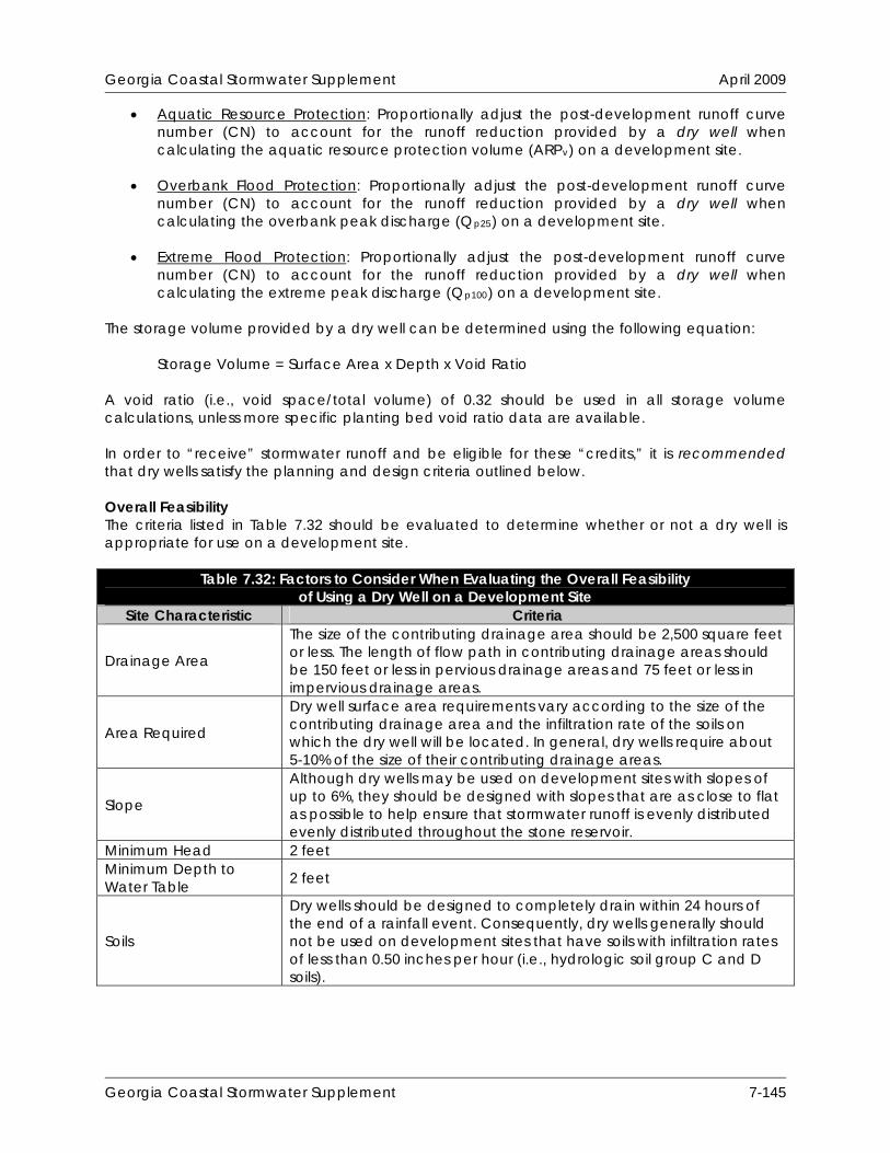
Georgia Coastal Stormwater Supplement April 2009
Aquatic Resource Protection: Proportionally adjust the post-development runoff curve number (CN) to account for the runoff reduction provided by a dry well when calculating the aquatic resource protection volume (ARPv) on a development site.
Overbank Flood Protection: Proportionally adjust the post-development runoff curve
number (CN) to account for the runoff reduction provided by a dry well when calculating the overbank peak discharge (Qp25) on a development site.
Extreme Flood Protection: Proportionally adjust the post-development runoff curve
number (CN) to account for the runoff reduction provided by a dry well when calculating the extreme peak discharge (Qp100) on a development site.
The storage volume provided by a dry well can be determined using the following equation:
Storage Volume = Surface Area x Depth x Void Ratio A void ratio (i.e., void space/total volume) of 0.32 should be used in all storage volume calculations, unless more specific planting bed void ratio data are available. In order to “receive” stormwater runoff and be eligible for these “credits,” it is recommended that dry wells satisfy the planning and design criteria outlined below. Overall Feasibility The criteria listed in Table 7.32 should be evaluated to determine whether or not a dry well is appropriate for use on a development site.
Table 7.32: Factors to Consider When Evaluating the Overall Feasibility of Using a Dry Well on a Development Site
Site Characteristic Criteria
Drainage Area
The size of the contributing drainage area should be 2,500 square feet or less. The length of flow path in contributing drainage areas should be 150 feet or less in pervious drainage areas and 75 feet or less in impervious drainage areas.
Area Required
Dry well surface area requirements vary according to the size of the contributing drainage area and the infiltration rate of the soils on which the dry well will be located. In general, dry wells require about 5-10% of the size of their contributing drainage areas.
Slope
Although dry wells may be used on development sites with slopes of up to 6%, they should be designed with slopes that are as close to flat as possible to help ensure that stormwater runoff is evenly distributed evenly distributed throughout the stone reservoir.
Minimum Head 2 feet Minimum Depth to Water Table 2 feet
Soils
Dry wells should be designed to completely drain within 24 hours of the end of a rainfall event. Consequently, dry wells generally should not be used on development sites that have soils with infiltration rates of less than 0.50 inches per hour (i.e., hydrologic soil group C and D soils).
Georgia Coastal Stormwater Supplement 7-145

Georgia Coastal Stormwater Supplement April 2009
Feasibility in Coastal Georgia Several site characteristics commonly encountered in coastal Georgia may present challenges to site planning and design teams that are interested in using dry wells to “receive” post-construction stormwater runoff on a development site. Table 7.33 identifies these common site characteristics and describes how they influence the use of dry wells on development sites. The table also provides site planning and design teams with some ideas about how they can work around these potential constraints.
Table 7.33: Challenges Associated with Using Dry Wells in Coastal Georgia
Site Characteristic How it Influences the Use of Dry Wells Potential Solutions
Poorly drained soils, such as hydrologic soil group C and D soils
Reduces the ability of dry wells to reduce stormwater runoff rates, volumes and pollutant loads.
Dry wells should not be used on development sites that have soils with infiltration rates of less than 0.5 inches per hour (i.e., hydrologic soil group C and D soils).
Use other low impact development practices, such as rainwater harvesting (Section 7.8.12) and underdrained bioretention areas (Section 7.8.13), to “receive” stormwater runoff in these areas.
Well drained soils, such as hydrologic soil group A and B soils
Enhances the ability of dry wells to reduce stormwater runoff rates, volumes and pollutant loads, but may allow stormwater pollutants to reach groundwater aquifers with greater ease.
Rooftop runoff is relatively clean, so this should not prevent the use of dry wells, even at stormwater hotspots and in areas known to provide groundwater recharge to water supply aquifers. However, rooftop runoff should not be allowed to comingle with runoff from other impervious surfaces in these areas if it will be “received” by a dry well.
Use bioretention areas (Section 7.8.13) and dry swales (Section 7.8.15) with liners and underdrains to intercept and treat non rooftop runoff at stormwater hotspots and in areas known to provide groundwater recharge to water supply aquifers.
Flat terrain Does not influence the use of dry wells. In fact, dry wells should be designed with slopes that are as close to flat as possible.
Georgia Coastal Stormwater Supplement 7-146

Georgia Coastal Stormwater Supplement April 2009
Table 7.33: Challenges Associated with Using Dry Wells in Coastal Georgia How it Influences the Use Site Characteristic Potential Solutions of Dry Wells
Shallow water table
May be difficult to provide 2 feet of clearance between the bottom of the dry well and the top of the water table.
May occasionally cause stormwater runoff to pond in the bottom of the dry well.
Ensure that the distance from the bottom of the dry well to the top of the water table is at least 2 feet.
Reduce the depth of the stone reservoir in dry wells to 18 inches.
Use rainwater harvesting (Section 7.8.12), small stormwater wetlands (i.e., pocket wetlands) (Section 8.6.2) or wet swales (Section 8.6.6), instead of dry wells to intercept and treat stormwater runoff in these areas.
Tidally-influenced drainage system
Does not influence the use of dry wells.
Site Applicability Dry wells can be used to “receive” stormwater runoff on a wide variety of development sites, including residential, commercial and institutional development sites in rural, suburban and urban areas. Although they are particularly well suited to “receive” rooftop runoff, they can also be used to “receive” stormwater runoff from other small drainage areas, such as local streets and roadways, driveways, small parking areas and disturbed pervious areas (e.g., lawns, parks, community open spaces). When compared with other low impact development practices, dry wells have a moderate construction cost, a moderate maintenance burden and require only a small amount of surface area. Planning and Design Criteria It is recommended that dry wells meet all of the following criteria to be eligible for the stormwater management “credits” described above: General Planning and Design
Dry wells should be used to “receive” stormwater runoff from small drainage areas of 2,500 square feet or less. The stormwater runoff rates and volumes from larger contributing drainage areas typically become too large to be properly “received” by a dry well.
The length of the flow path within the contributing drainage area should be 150 feet or less for pervious drainage areas and 75 feet or less for impervious drainage areas. In contributing drainage areas with longer flow paths, stormwater runoff tends to becomes shallow, concentrated flow (Claytor and Schueler, 1996), which can significantly reduce the stormwater management benefits that dry wells can provide. In these situations, bioretention areas (Section 7.8.13) and infiltration practices (Section 7.8.14) should be used to “receive” post-construction stormwater runoff.
Although dry wells may be installed on development sites with slopes of up to 6%, they should be designed with slopes that are as close to flat as possible to help ensure that stormwater runoff is evenly distributed throughout the stone reservoir.
Dry wells should be located in a lawn or other disturbed pervious area and should be designed so that the top of the dry well is located as close to the surface as possible. Dry wells should not be located beneath a driveway, parking lot or other impervious surface.
Georgia Coastal Stormwater Supplement 7-147
Georgia Coastal Stormwater Supplement April 2009
Dry wells should be used on development sites that have underlying soils with an infiltration rate of 0.50 inches per hour (in/hr) or greater, as determined by NRCS soil survey data and subsequent field testing. Field infiltration test protocol, such as that provided by the City of Portland, OR (Portland, OR, 2008) on the following website: http://www.portlandonline.com/shared/cfm/image.cfm?id= 202911, can be used to conduct field testing, but should be approved by the local development review authority prior to use.
Although the number of infiltration tests needed on a development site will ultimately be determined by the local development review authority, at least one infiltration test is recommended for each dry well that will be used on the development site.
Since clay lenses or any other restrictive layers located below the bottom of a dry well will reduce soil infiltration rates, infiltration testing should be conducted within any confining layers that are found within 4 feet of the bottom of a proposed dry well.
Dry wells should be designed to provide enough storage for the stormwater runoff volume generated by the target runoff reduction rainfall event (e.g., 85th percentile rainfall event). Since they are essentially infiltration practices, the required dimensions of a dry well can be determined using the design procedures provided in Section 8.6.5 of this CSS.
Dry wells should be designed to completely drain within 24 hours of the end of a rainfall event. Where site characteristics allow, it is preferable to design dry wells to drain within 12 hours of the end of a rainfall event to help prevent the formation of nuisance ponding conditions.
Broader, shallower dry wells perform more effectively by distributing stormwater runoff over a larger surface area. However, a minimum depth of 18 inches is recommended for all dry well designs to prevent them from consuming a large amount of surface area on development sites. Whenever practical, the depth of dry wells should be kept to 36 inches or less.
Dry wells should be filled with clean, washed stone. The stone used in the dry well should be 1.5 to 2.5 inches in diameter, with a void space of approximately 40% (e.g., GA DOT No. 3 Stone). Unwashed aggregate contaminated with soil or other fines may not be used in the dry well.
Underlying native soils should be separated from the dry well stone by a thin, 2 to 4 inch layer of choker stone (i.e., ASTM D 448 size No. 8, 3/8” to 1/8” or ASTM D 448 size No. 89, 3/8” to 1/16”). The choker stone should be placed between the dry well stone and the underlying native soils.
The top and sides of the dry well should be lined with a layer of appropriate permeable filter fabric. The filter fabric should be a non-woven geotextile with a permeability that is greater than or equal to the infiltration rate of the surrounding native soils. The top layer of the filter fabric should be located 6 inches from the top of the excavation, with the remaining space filled with appropriate landscaping. This top layer serves as a sediment barrier and, consequently, will need to be replaced over time. Site planning and design teams should ensure that the top layer of filter fabric can be readily separated from the filter fabric used to line the sides of the dry well.
The depth from the bottom of a dry well to the top of the water table should be at least 2 feet to prevent nuisance ponding and ensure proper operation of the dry well.
To prevent damage to building foundations and contamination of groundwater aquifers, dry wells should be located at least:
o 10 feet from building foundations o 10 feet from property lines o 100 feet from private water supply wells o 1,200 feet from public water supply wells o 100 feet from septic systems
Georgia Coastal Stormwater Supplement 7-148
Georgia Coastal Stormwater Supplement April 2009
o 100 feet from surface waters o 400 feet from public water supply surface waters
An observation well should be installed in every dry well. An observation well consists of a 4 to 6 inch perforated PVC (AASHTO M 252) pipe that extends to the bottom of the dry well. The observation well can be used to observe the rate of drawdown within the dry well following a storm event. It should be installed along the centerline of the dry well, flush with the elevation of the surface of the dry well. A visible floating marker should be provided within the observation well and the top of the well should be capped and locked to prevent tampering and vandalism. Appendix B in Volume 2 of the Georgia Stormwater Management Manual provides additional information about observation wells.
If used to “receive” rooftop runoff, dry wells should be preceded by a leaf screen installed in the gutter or downspout. This will prevent leaves and other large debris from clogging the dry well.
If used to “receive” non rooftop runoff, dry wells should be preceded by a pea gravel diaphragm or equivalent level spreader device (e.g., concrete sills, curb stops, curbs with “sawteeth” cut into them) and a vegetated filter strip that is designed according to the planning and design criteria provided in Section 7.8.6 of this CSS.
Consideration should be given to the stormwater runoff rates and volumes generated by larger storm events (e.g., 25-year, 24-hour storm event) to help ensure that these larger storm events are able to safely bypass the dry well. An overflow, such as a vegetated filter strip (Section 7.8.6) or grass channel (Section 7.8.7), should be designed to convey the stormwater runoff generated by these larger storm events safely out of the dry well.
Landscaping
The landscaped area above the surface of a dry well may be covered with pea gravel (i.e., ASTM D 448 size No. 8, 3/8” to 1/8”). This pea gravel layer provides sediment removal and additional pretreatment upstream of the dry well and can be easily removed and replaced when it becomes clogged.
Alternatively, a dry well may be covered with an engineered soil mix, such as that prescribed in Section 7.8.9 of this CSS, and planted with managed turf or other herbaceous vegetation. This may be an attractive option when dry wells are placed in disturbed pervious areas (e.g., lawns, parks, community open spaces).
Construction Considerations To help ensure that dry wells are successfully installed on a development site, site planning and design teams should consider the following recommendations:
If dry wells will be used to “receive” non rooftop runoff, they should only be installed after their contributing drainage areas have been completely stabilized. To help prevent dry well failure, stormwater runoff may be diverted around the dry well until the contributing drainage area has been stabilized.
To help prevent soil compaction, heavy vehicular and foot traffic should be kept out of dry wells before, during and immediately after construction. This can typically be accomplished by clearly delineating dry wells on all development plans and, if necessary, protecting them with temporary construction fencing.
Excavation for dry wells should be limited to the width and depth specified in the development plans. Excavated material should be placed away from the excavation so as not to jeopardize the stability of the side walls.
The native soils along the bottom of the dry well should be scarified or tilled to a depth of 3 to 4 inches prior to the placement of the choker stone and dry well stone.
Georgia Coastal Stormwater Supplement 7-149

Georgia Coastal Stormwater Supplement April 2009
The sides of all excavations should be trimmed of all large roots that will hamper the installation of the permeable filter fabric used to line the sides and top of the dry well.
Maintenance Requirements Maintenance is important for dry wells, particularly in terms of ensuring that they continue to provide measurable stormwater management benefits over time. Consequently, a legally-binding inspection and maintenance agreement and plan should be put in place to ensure that dry wells are regularly maintained after occupancy. Table 7.34 provides a list of the routine maintenance activities typically associated with dry wells.
Table 7.34: Routine Maintenance Activities Typically Associated with Dry Wells Activity Schedule
If used to “receive” non rooftop runoff, ensure that the contributing drainage area is stabilized prior to installation of the dry well.
If applicable, water to promote plant growth and survival within landscaped area over the top of the dry well.
If applicable, inspect vegetative cover on the surface of the dry well following rainfall events. Plant replacement vegetation in any eroded areas.
As Needed (During Construction)
If applicable, inspect gutters and downspouts. Remove any accumulated leaves or debris.
Inspect dry well following rainfall events. Check observation well to ensure that complete drawdown has occurred within 72 hours after the end of a rainfall event. Failure to drawdown within this timeframe may indicate dry well failure.
If applicable, inspect pretreatment devices for sediment accumulation. Remove accumulated trash and debris.
Inspect top layer of filter fabric for sediment accumulation. Remove and replace if clogged.
Annually (Semi-Annually During First Year)
Perform total rehabilitation of the dry well, removing dry well stone and excavating to expose clean soil on the sides and bottom of the well.
Upon Failure
Additional Resources City of Portland, OR. 2008. “Soakage Trench.” Portland Stormwater Management Manual.
Section 2.3.3. City of Portland, OR. Bureau of Environmental Services. Available Online: http://www.portlandonline.com/bes/index.cfm?c=47952.
City of Portland, OR. 2008. “Dry Well.” Portland Stormwater Management Manual. Section 2.3.3.
City of Portland, OR. Bureau of Environmental Services. Available Online: http://www.portlandonline.com/bes/index.cfm?c=47952.
Atlanta Regional Commission (ARC). 2001. “Infiltration Trench.” Georgia Stormwater
Management Manual. Volume 2. Technical Handbook. Section 3.2.5. Atlanta Regional Commission. Atlanta, GA. Available Online: http://www.georgia stormwater.com/.
Georgia Coastal Stormwater Supplement 7-150

Georgia Coastal Stormwater Supplement April 2009
7.8.12 Rainwater Harvesting Description Rainwater harvesting is the ancient stormwater management practice of intercepting, diverting and storing rainfall for later use. In a typical rainwater harvesting system, rainfall is collected from a gutter and downspout system, screened and “washed,” and conveyed into an above- or below-ground storage tank or cistern. Once captured in the storage tank or cistern, it may be used for non-potable indoor or outdoor uses. If properly designed, rainwater harvesting systems can significantly reduce post-construction stormwater runoff rates, volumes and pollutant loads on development sites. Rainwater harvesting also helps reduce the demand on public water supplies, which, in turn, helps protect aquatic resources, such as groundwater aquifers, from drawdown and seawater intrusion.
STORMWATER MANAGEMENT
“CREDITS”
Runoff Reduction Water Quality Protection Aquatic Resource Protection Overbank Flood Protection Extreme Flood Protection = practice has been assigned quantifiable stormwater management “credits” that can be used to address this SWM Criteria
KEY CONSIDERATIONS
DESIGN CRITERIA:
Rainwater harvesting systems should be sized based on the size of the contributing drainage area, local rainfall patterns and the projected demand for the harvested rainwater
Pretreatment should be provided upstream of all rainwater harvesting systems to prevent leaves and other debris from clogging the system
BENEFITS:
Helps restore pre-development hydrology on development sites and reduces post-construction stormwater runoff rates, volumes and pollutant loads
Can be used on nearly any development site Reduces demand on public water supplies,
which helps protect groundwater aquifers from drawdown and seawater intrusion
LIMITATIONS:
Rain barrels may not be used except on small drainage areas of 2,500 square feet or less
Stored rainwater should be used on a regular basis to maintain system storage capacity
SITE APPLICABILITY
Rural Use Suburban Use Urban Use
M Construction Cost H Maintenance L Area Required
STORMWATER MANAGEMENT
PRACTICE PERFORMANCE Runoff Reduction Varies1 - Annual Runoff Volume Varies1 - Runoff Reduction Volume Pollutant Removal2 Varies1 - Total Suspended Solids Varies1 - Total Phosphorus Varies1 - Total Nitrogen Varies1 - Metals N/A - Pathogens 1 = varies according to storage capacity of the rainwater harvesting system 2 = expected annual pollutant load removal
(Source: Jones and Hunt, 2008)
Georgia Coastal Stormwater Supplement 7-151
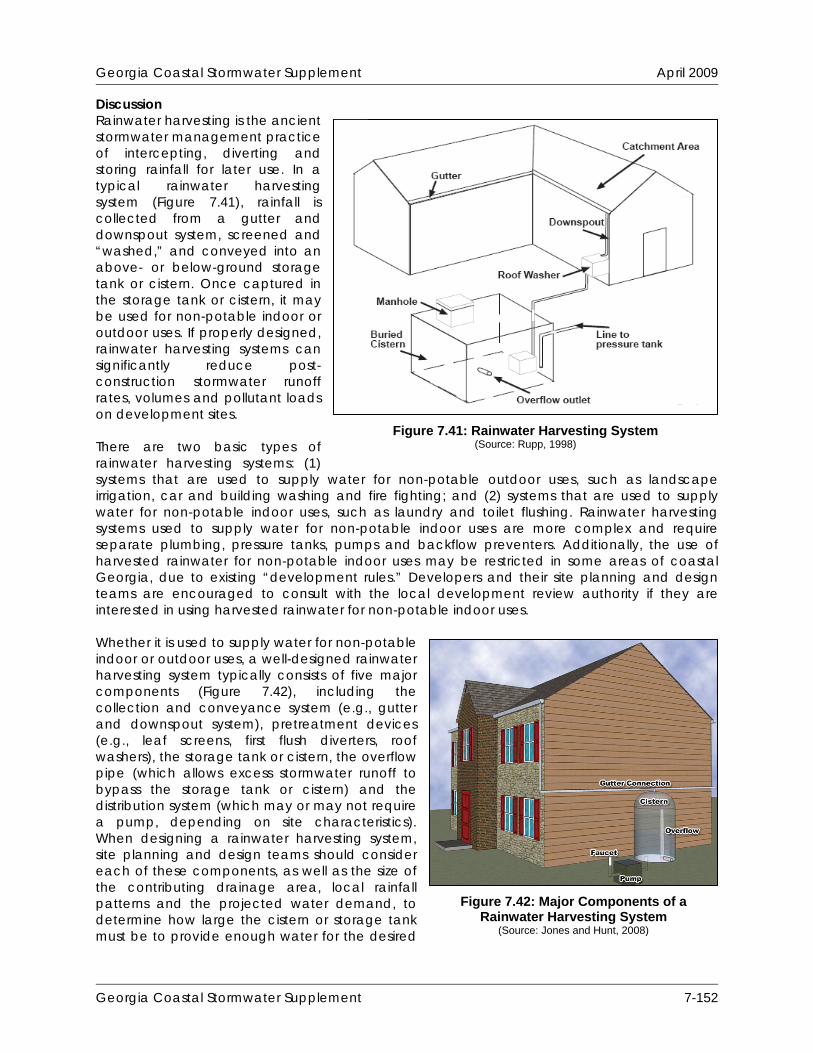
Georgia Coastal Stormwater Supplement April 2009
Discussion Rainwater harvesting is the ancient stormwater management practice of intercepting, diverting and storing rainfall for later use. In a typical rainwater harvesting system (Figure 7.41), rainfall is collected from a gutter and downspout system, screened and “washed,” and conveyed into an above- or below-ground storage tank or cistern. Once captured in the storage tank or cistern, it may be used for non-potable indoor or outdoor uses. If properly designed, rainwater harvesting systems can significantly reduce post-construction stormwater runoff rates, volumes and pollutant loads on development sites. There are two basic types of rainwater harvesting systems: (1) systems that are used to supply water for non-potable outdoor uses, such as landscape irrigation, car and building washing and fire fighting; and (2) systems that are used to supply water for non-potable indoor uses, such as laundry and toilet flushing. Rainwater harvesting systems used to supply water for non-potable indoor uses are more complex and require separate plumbing, pressure tanks, pumps and backflow preventers. Additionally, the use of harvested rainwater for non-potable indoor uses may be restricted in some areas of coastal Georgia, due to existing “development rules.” Developers and their site planning and design teams are encouraged to consult with the local development review authority if they are interested in using harvested rainwater for non-potable indoor uses. Whether it is used to supply water for non-potable indoor or outdoor uses, a well-designed rainwater harvesting system typically consists of five major components (Figure 7.42), including the collection and conveyance system (e.g., gutter and downspout system), pretreatment devices (e.g., leaf screens, first flush diverters, roof washers), the storage tank or cistern, the overflow pipe (which allows excess stormwater runoff to bypass the storage tank or cistern) and the distribution system (which may or may not require a pump, depending on site characteristics). When designing a rainwater harvesting system, site planning and design teams should consider each of these components, as well as the size of the contributing drainage area, local rainfall patterns and the projected water demand, to determine how large the cistern or storage tank must be to provide enough water for the desired
Figure 7.42: Major Components of a Rainwater Harvesting System
(Source: Jones and Hunt, 2008)
Figure 7.41: Rainwater Harvesting System (Source: Rupp, 1998)
Georgia Coastal Stormwater Supplement 7-152

Georgia Coastal Stormwater Supplement April 2009
non-potable indoor or outdoor use. Stormwater Management “Credits” The Center for Watershed Protection (Hirschman et al., 2008) recently documented the ability of rainwater harvesting systems to reduce annual stormwater runoff volumes and pollutant loads on development sites. Consequently, this low impact development practice has been assigned quantifiable stormwater management “credits” that can be used to help satisfy the SWM Criteria presented in this CSS:
Stormwater Runoff Reduction: Subtract 75% of the storage volume provided by a rainwater harvesting system from the runoff reduction volume (RRv) captured by the system.
Water Quality Protection: Subtract 75% of the storage volume provided by a rainwater
harvesting system from the runoff reduction volume (RRv) captured by the system.
Aquatic Resource Protection: Proportionally adjust the post-development runoff curve number (CN) to account for the runoff reduction provided by a rainwater harvesting system when calculating the aquatic resource protection volume (ARPv) on a development site.
Overbank Flood Protection: Proportionally adjust the post-development runoff curve
number (CN) to account for the runoff reduction provided by a rainwater harvesting system when calculating the overbank peak discharge (Qp25) on a development site.
Extreme Flood Protection: Proportionally adjust the post-development runoff curve
number (CN) to account for the runoff reduction provided by a rainwater harvesting system when calculating the extreme peak discharge (Qp100) on a development site.
Only 75% of the storage volume provided by a rainwater harvesting system can be subtracted from the runoff reduction volume (RRv) that is captured by the system due to the fact that some of the harvested rainwater may not be used between consecutive storm events. In order to “receive” stormwater runoff and be eligible for these “credits,” it is recommended that rainwater harvesting systems satisfy the planning and design criteria outlined below. Overall Feasibility The criteria listed in Table 7.35 should be evaluated to determine whether or not a rainwater harvesting system is appropriate for use on a development site. It is important to note that rainwater harvesting systems have few constraints that impede their use on development sites.
Table 7.35: Factors to Consider When Evaluating the Overall Feasibility of Using a Rainwater Harvesting System on a Development Site
Site Characteristic Criteria Drainage Area No restrictions
Area Required Varies according to the size of the contributing drainage area and the dimensions of the rain tank or cistern used to store the harvested rainwater.
Slope No restrictions, although placing rainwater harvesting systems at higher elevations may reduce or eliminate pumping requirements.
Minimum Head N/A
Georgia Coastal Stormwater Supplement 7-153

Georgia Coastal Stormwater Supplement April 2009
Table 7.35: Factors to Consider When Evaluating the Overall Feasibility of Using a Rainwater Harvesting System on a Development Site
Site Characteristic Criteria Minimum Depth to Water Table N/A
Soils N/A Site Applicability Rainwater harvesting systems can be used on a wide variety of development sites in rural, suburban and urban areas. They are especially well suited for use on commercial, institutional, municipal and multi-family residential buildings on urban and suburban development and redevelopment sites. When compared with other low impact development practices, rainwater harvesting systems have a moderate construction cost, a relatively high maintenance burden and require a relatively small amount of surface area. Although they can be expensive to install, rainwater harvesting systems are often a component of “green buildings,” such as those that achieve certification in the Leadership in Energy and Environmental Design (LEED) Green Building Rating System. Planning and Design Criteria It is recommended that rainwater harvesting systems meet all of the following criteria to be eligible for the stormwater management “credits” described above: General Planning and Design
Rainwater harvesting systems may be installed on nearly any development site. However, placing storage tanks or cisterns at higher elevations may reduce or eliminate pumping requirements.
The quality of harvested rainwater will vary according to the material from which the rooftop is constructed. Water harvested from certain types of rooftops, such as asphalt shingle, tar and gravel and treated wood shingle roofs, should only be used for non-potable outdoor uses, as these materials may leach toxic compounds into stormwater runoff.
Rainwater harvesting systems should be designed to provide at least enough storage for the stormwater runoff volume generated by the target runoff reduction rainfall event (e.g., 85th percentile rainfall event). The required size of a rainwater harvesting system is governed by several factors, including the size of the contributing drainage area, local rainfall patterns and the projected demand for the harvested rainwater. Site planning and design teams should calculate the projected water demand and then conduct water balance calculations, based on the size of the contributing drainage area and local precipitation data, to size a rainwater harvesting system. A rainwater harvesting model, such as the one provided by North Carolina State University (NCSU, 2008) on the following website: http://www.bae.ncsu.edu/topic/waterharvesting, can be used to design a rainwater harvesting system, provided that the precipitation data being used in the model reflects local rainfall patterns and distributions and has been approved by the local development review authority prior to use.
Since it provides storage for the harvested rainwater, the storage tank (also known as a cistern) is the most important and typically the most expensive component of a rainwater harvesting system. Storage tanks can be constructed from a variety of materials, including wood, plastic, fiberglass or galvanized metal. Site planning and design teams should choose an appropriate cistern for the intended application and should ensure that it has been sealed with a water safe, non-toxic substance.
Rain barrels (i.e., small storage tanks capable of storing less than 100 gallons of stormwater runoff) rarely provide enough storage capacity to accommodate the
Georgia Coastal Stormwater Supplement 7-154

Georgia Coastal Stormwater Supplement April 2009
stormwater runoff volume generated by the target runoff reduction rainfall event. Consequently, they should not be used as part of a rainwater harvesting system, except on small drainage areas of 2,500 square feet or less in size.
All storage tanks should be opaque or otherwise protected from direct sunlight to inhibit algae growth. They should also be screened to discourage mosquito breeding and reproduction, but should be accessible for cleaning, inspection and maintenance.
Rooftop drainage systems (e.g., gutter and downspout systems) should be designed as they would be for a building designed without a rainwater harvesting system. Drainage system components leading to the cistern should have a minimum slope of 2% to ensure that harvested rainwater is actually conveyed into the storage tank.
Pretreatment is needed to remove debris, dust, leaves and other material that accumulates on rooftops, as it may cause clogging within a rainwater harvesting system. Pretreatment devices that may be used include leaf screens, roof washers and first-flush diverters, each of which are described briefly below:
o Leaf Screens: Leaf screens are mesh screens installed either in the gutter or downspout that are used to remove leaves and other large debris from rooftop runoff. Leaf screens must be regularly cleaned to be effective. If not regularly maintained, they can become clogged and prevent rainwater from flowing into the storage tank.
o First Flush Diverters: First flush diverters direct the initial pulse of stormwater runoff away from the storage tank and into an adjacent pervious area. While leaf screens effectively remove larger debris such as leaves and twigs from harvested rainwater, first flush diverters can be used to remove smaller contaminants such as dust, pollen and bird and rodent feces.
o Roof Washers: Roof washers are placed just ahead of storage tanks and are used to filter small debris from the harvested rainwater. Roof washers consist of a small tank, usually between 25 and 50 gallons in size, with leaf strainers and filters with openings as small as 30 microns (TWDB, 2005). The filter functions to remove very small particulate matter from harvested rainwater. All roof washers must be cleaned on a regular basis. Without regular maintenance, they may not only become clogged and prevent rainwater from entering the storage tank, but may become breeding grounds for bacteria and other pathogens.
An overflow pipe should be provided to allow stormwater runoff to bypass the storage tank or cistern when it reaches its storage capacity. The overflow pipe should have a conveyance capacity that is equal to or greater than that of the inflow pipe and should direct excess stormwater runoff to another low impact development practice, such as a vegetated filter strip (Section 7.8.6), grass channel (Section 7.8.7) or rain garden (Section 7.8.9).
All overflow pipes should be directed away from adjacent buildings to prevent damage to building foundations.
Distribution systems may be gravity fed or may include a pump to provide the energy necessary to convey harvested rainwater from the storage tank to its final destination. Rainwater harvesting systems used to provide water for non-potable outdoor uses typically use gravity to feed watering hoses through a tap and spigot arrangement.
Construction Considerations To help ensure that rainwater harvesting systems are successfully installed on a development site, site planning and design teams should consider the following recommendations:
Rainwater harvesting systems may be installed on development and redevelopment sites after building rooftops and rooftop drainage systems (e.g., gutter and downspout systems) have been constructed.
Georgia Coastal Stormwater Supplement 7-155

Georgia Coastal Stormwater Supplement April 2009
Maintenance Requirements Maintenance is important for rainwater harvesting systems, particularly in terms of ensuring that they continue to provide measurable stormwater management benefits over time. Consequently, a legally-binding inspection and maintenance agreement and plan should be put in place to ensure that rainwater harvesting systems are regularly maintained after occupancy. Table 7.36 provides a list of the routine maintenance activities typically associated with rainwater harvesting systems.
Table 7.36: Routine Maintenance Activities Typically Associated with Rainwater Harvesting Systems
Activity Schedule Inspect storage tank screens and pretreatment
devices. Clean as needed. Regularly (Monthly)
Inspect gutters and downspouts. Remove any accumulated leaves or debris.
Clean storage tank screens. Inspect pretreatment devices for sediment
accumulation. Remove accumulated trash and debris.
Inspect storage tank for algal blooms. Treat as necessary.
Inspect overflow areas for erosion and the formation of rills and gullies. Plant replacement vegetation in any eroded areas.
Annually (Semi-Annually During First Year)
Additional Resources Texas Water Development Board (TWDB). 2005. The Texas Manual on Rainwater Harvesting. 3rd
Edition. Texas Water Development Board. Austin, TX. Available Online: http://www.twdb.state.tx.us/publications/reports/RainwaterHarvestingManual_3rdedition
.pdf. Rupp, G. 1998. Rainwater Harvesting Systems for Montana. Montana State University Extension
Service. Bozeman, MT. Available Online: http://www.montana.edu/wwwpb/pubs/mt9707.html.
City of Portland, OR. 2008. “Rainwater Harvesting.” Portland Stormwater Management Manual.
Section 2.3.3. City of Portland, OR. Bureau of Environmental Services. Available Online: http://www.portlandonline.com/bes/index.cfm?c=47952.
Jones, M.P. and W.F. Hunt. 2008. Rainwater Harvesting: Guidance for Homeowners. North
Carolina Cooperative Extension Service Bulletin. Urban Waterways Series. AGW-588-11. North Carolina State University. Raleigh, NC. Available Online: http://www.bae.ncsu.edu/stormwater/PublicationFiles/WaterHarvestHome2008.pdf.
Georgia Coastal Stormwater Supplement 7-156

Georgia Coastal Stormwater Supplement April 2009
7.8.13 Bioretention Areas Description Bioretention areas, which may also be classified as a stormwater management practice (Section 8.6.3), are shallow depressional areas that are filled with an engineered soil mix and are planted with trees, shrubs and other herbaceous vegetation. They are designed to capture and temporarily store stormwater runoff in the engineered soil mix, where it is subjected to the hydrologic processes of evaporation and transpiration, before being conveyed back into the storm drain system through an underdrain or allowed to infiltrate into the surrounding soils. This allows them to provide measurable reductions in post-construction stormwater runoff rates, volumes and pollutant loads on development sites. (Source: Center for Watershed Protection)
STORMWATER MANAGEMENT “CREDITS”
Runoff Reduction Water Quality Protection Aquatic Resource Protection Overbank Flood Protection Extreme Flood Protection = practice has been assigned quantifiable stormwater management “credits” that can be used to address this SWM Criteria
KEY CONSIDERATIONS
DESIGN CRITERIA:
Bioretention areas should be designed to completely drain within 48 hours of the end of a rainfall event
A maximum ponding depth of 9 inches is recommended within bioretention areas to help prevent the formation of nuisance ponding conditions
Unless a shallow water table is found on the development site, bioretention area planting beds should be at least 3 feet deep
BENEFITS:
Helps restore pre-development hydrology on development sites and reduces post-construction stormwater runoff rates, volumes and pollutant loads
Can be integrated into development plans as attractive landscaping features
LIMITATIONS:
Can only be used to “receive” runoff from relatively small drainage areas of 5 acres in size
SITE APPLICABILITY
Rural Use Suburban Use Urban Use
M Construction Cost M Maintenance L Area Required
STORMWATER MANAGEMENT
PRACTICE PERFORMANCE Runoff Reduction 40%/80% - Annual Runoff Volume Varies1 - Runoff Reduction Volume Pollutant Removal2 80% - Total Suspended Solids 60% - Total Phosphorus 60% - Total Nitrogen N/A - Metals 80% - Pathogens 1 = varies according to storage capacity of the bioretention area 2 = expected annual pollutant load removal
Georgia Coastal Stormwater Supplement 7-157
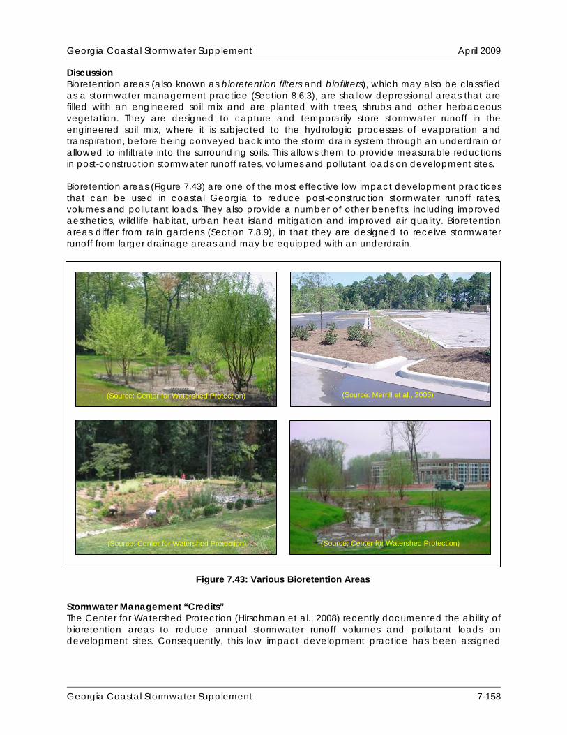
Georgia Coastal Stormwater Supplement April 2009
Discussion Bioretention areas (also known as bioretention filters and biofilters), which may also be classified as a stormwater management practice (Section 8.6.3), are shallow depressional areas that are filled with an engineered soil mix and are planted with trees, shrubs and other herbaceous vegetation. They are designed to capture and temporarily store stormwater runoff in the engineered soil mix, where it is subjected to the hydrologic processes of evaporation and transpiration, before being conveyed back into the storm drain system through an underdrain or allowed to infiltrate into the surrounding soils. This allows them to provide measurable reductions in post-construction stormwater runoff rates, volumes and pollutant loads on development sites. Bioretention areas (Figure 7.43) are one of the most effective low impact development practices that can be used in coastal Georgia to reduce post-construction stormwater runoff rates, volumes and pollutant loads. They also provide a number of other benefits, including improved aesthetics, wildlife habitat, urban heat island mitigation and improved air quality. Bioretention areas differ from rain gardens (Section 7.8.9), in that they are designed to receive stormwater runoff from larger drainage areas and may be equipped with an underdrain.
(Source: Merrill et al., 2006) (Source: Center for Watershed Protection)
(Source: Center for Watershed Protection) (Source: Center for Watershed Protection)
Figure 7.43: Various Bioretention Areas
Stormwater Management “Credits” The Center for Watershed Protection (Hirschman et al., 2008) recently documented the ability of bioretention areas to reduce annual stormwater runoff volumes and pollutant loads on development sites. Consequently, this low impact development practice has been assigned
Georgia Coastal Stormwater Supplement 7-158

Georgia Coastal Stormwater Supplement April 2009
quantifiable stormwater management “credits” that can be used to help satisfy the SWM Criteria presented in this CSS:
Stormwater Runoff Reduction: Subtract 100% of the storage volume provided by a non-underdrained bioretention area from the runoff reduction volume (RRv) conveyed through the bioretention area. Subtract 50% of the storage volume provided by an underdrained bioretention area from the runoff reduction volume (RRv) conveyed through the bioretention area.
Water Quality Protection: Subtract 100% of the storage volume provided by a non-
underdrained bioretention area from the runoff reduction volume (RRv) conveyed through the bioretention area. Subtract 50% of the storage volume provided by an underdrained bioretention area from the runoff reduction volume (RRv) conveyed through the bioretention area.
Aquatic Resource Protection: Proportionally adjust the post-development runoff curve
number (CN) to account for the runoff reduction provided by a bioretention area when calculating the aquatic resource protection volume (ARPv) on a development site.
Overbank Flood Protection: Proportionally adjust the post-development runoff curve
number (CN) to account for the runoff reduction provided by a bioretention area when calculating the overbank peak discharge (Qp25) on a development site.
Extreme Flood Protection: Proportionally adjust the post-development runoff curve
number (CN) to account for the runoff reduction provided by a bioretention area when calculating the extreme peak discharge (Qp100) on a development site.
The storage volume provided by a bioretention area can be determined using the following equation:
Storage Volume = Surface Area x [Ponding Depth + (Depth of Planting Bed x Void Ratio)] A void ratio (i.e., void space/total volume) of 0.32 should be used in all storage volume calculations, unless more specific planting bed void ratio data are available. In order to “receive” stormwater runoff and be eligible for these “credits,” it is recommended that bioretention areas satisfy the planning and design criteria outlined below. Overall Feasibility The criteria listed in Table 7.37 should be evaluated to determine whether or not a bioretention area is appropriate for use on a development site.
Table 7.37: Factors to Consider When Evaluating the Overall Feasibility of Using a Bioretention Area on a Development Site
Site Characteristic Criteria
Drainage Area
Although bioretention areas can be used to “receive” stormwater runoff from contributing drainage areas as large as 5 acres in size, contributing drainage areas of between 2,500 square feet and 2 acres are preferred.
Georgia Coastal Stormwater Supplement 7-159
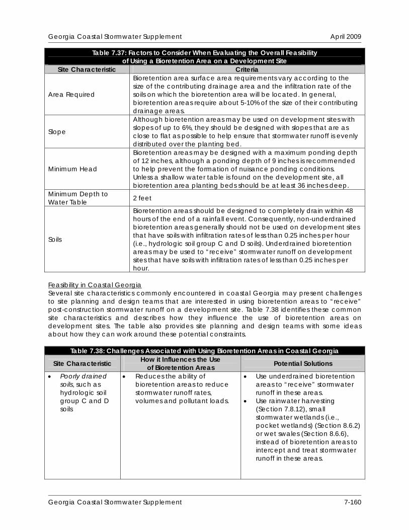
Georgia Coastal Stormwater Supplement April 2009
Table 7.37: Factors to Consider When Evaluating the Overall Feasibility of Using a Bioretention Area on a Development Site
Site Characteristic Criteria
Area Required
Bioretention area surface area requirements vary according to the size of the contributing drainage area and the infiltration rate of the soils on which the bioretention area will be located. In general, bioretention areas require about 5-10% of the size of their contributing drainage areas.
Slope
Although bioretention areas may be used on development sites with slopes of up to 6%, they should be designed with slopes that are as close to flat as possible to help ensure that stormwater runoff is evenly distributed over the planting bed.
Minimum Head
Bioretention areas may be designed with a maximum ponding depth of 12 inches, although a ponding depth of 9 inches is recommended to help prevent the formation of nuisance ponding conditions. Unless a shallow water table is found on the development site, all bioretention area planting beds should be at least 36 inches deep.
Minimum Depth to Water Table 2 feet
Soils
Bioretention areas should be designed to completely drain within 48 hours of the end of a rainfall event. Consequently, non-underdrained bioretention areas generally should not be used on development sites that have soils with infiltration rates of less than 0.25 inches per hour (i.e., hydrologic soil group C and D soils). Underdrained bioretention areas may be used to “receive” stormwater runoff on development sites that have soils with infiltration rates of less than 0.25 inches per hour.
Feasibility in Coastal Georgia Several site characteristics commonly encountered in coastal Georgia may present challenges to site planning and design teams that are interested in using bioretention areas to “receive” post-construction stormwater runoff on a development site. Table 7.38 identifies these common site characteristics and describes how they influence the use of bioretention areas on development sites. The table also provides site planning and design teams with some ideas about how they can work around these potential constraints.
Table 7.38: Challenges Associated with Using Bioretention Areas in Coastal Georgia
Site Characteristic How it Influences the Use of Bioretention Areas Potential Solutions
Poorly drained soils, such as hydrologic soil group C and D soils
Reduces the ability of bioretention areas to reduce stormwater runoff rates, volumes and pollutant loads.
Use underdrained bioretention areas to “receive” stormwater runoff in these areas.
Use rainwater harvesting (Section 7.8.12), small stormwater wetlands (i.e., pocket wetlands) (Section 8.6.2) or wet swales (Section 8.6.6), instead of bioretention areas to intercept and treat stormwater runoff in these areas.
Georgia Coastal Stormwater Supplement 7-160

Georgia Coastal Stormwater Supplement April 2009
Table 7.38: Challenges Associated with Using Bioretention Areas in Coastal Georgia How it Influences the Use Site Characteristic Potential Solutions of Bioretention Areas
Well drained soils, such as hydrologic soil group A and B soils
Enhances the ability of bioretention areas to reduce stormwater runoff rates, volumes and pollutant loads, but may allow stormwater pollutants to reach groundwater aquifers with greater ease.
Avoid the use of infiltration-based low impact development practices, including non-underdrained bioretention areas, at stormwater hotspots and in areas known to provide groundwater recharge to water supply aquifers, unless adequate pretreatment is provided upstream of them.
Use bioretention areas and dry swales (Section 7.8.15) with liners and underdrains at stormwater hotspots and in areas known to provide groundwater recharge to water supply aquifers.
Flat terrain May be difficult to provide adequate drainage and may cause stormwater runoff to pond in the bioretention area for extended periods of time.
Ensure that the underlying native soils will allow the bioretention area to drain completely within 48 hours of the end of a rainfall event to prevent the formation of nuisance ponding conditions.
Shallow water table
May be difficult to provide 2 feet of clearance between the bottom of the bioretention area and the top of the water table.
May occasionally cause stormwater runoff to pond in the bioretention area.
Ensure that the distance from the bottom of the bioretention area to the top of the water table is at least 2 feet.
Reduce the depth of the planting bed to 18 inches.
Use stormwater ponds (Section 8.6.1), stormwater wetlands (Section 8.6.2) and wet swales (Section 8.6.6), instead of bioretention areas to intercept and treat stormwater runoff in these areas.
Tidally-influenced drainage system
May occasionally prevent stormwater runoff from being conveyed through a bioretention area, particularly during high tide.
Investigate the use of other low impact development practices, such as rainwater harvesting (Section 7.8.12) to “receive” stormwater runoff in these areas.
Site Applicability Bioretention areas can be used to “receive” stormwater runoff on a wide variety of development sites, including residential, commercial and institutional development sites in rural, suburban and urban areas. They are well suited to “receive” stormwater runoff from nearly all small impervious and pervious drainage areas, including local streets and roadways, highways, driveways, small parking areas and disturbed pervious areas (e.g., lawns, parks, community
Georgia Coastal Stormwater Supplement 7-161

Georgia Coastal Stormwater Supplement April 2009
open spaces). When compared with other low impact development practices, bioretention areas have a moderate construction cost, a moderate maintenance burden and require a relatively small amount of surface area. Planning and Design Criteria Additional information regarding the planning and design of bioretention areas is provided in Section 8.6.3.
Georgia Coastal Stormwater Supplement 7-162
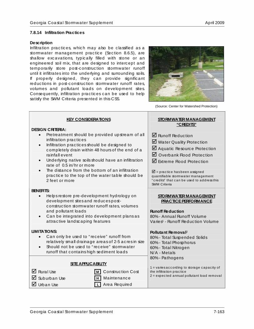
Georgia Coastal Stormwater Supplement April 2009
7.8.14 Infiltration Practices Description Infiltration practices, which may also be classified as a stormwater management practice (Section 8.6.5), are shallow excavations, typically filled with stone or an engineered soil mix, that are designed to intercept and temporarily store post-construction stormwater runoff until it infiltrates into the underlying and surrounding soils. If properly designed, they can provide significant reductions in post-construction stormwater runoff rates, volumes and pollutant loads on development sites. Consequently, infiltration practices can be used to help satisfy the SWM Criteria presented in this CSS.
(Sour tion) ce: Center for Watershed Protec
STORMWATER MANAGEMENT
“CREDITS”
Runoff Reduction Water Quality Protection Aquatic Resource Protection Overbank Flood Protection Extreme Flood Protection = practice has been assigned quantifiable stormwater management “credits” that can be used to address this SWM Criteria
KEY CONSIDERATIONS
DESIGN CRITERIA:
Pretreatment should be provided upstream of all infiltration practices
Infiltration practices should be designed to completely drain within 48 hours of the end of a rainfall event
Underlying native soils should have an infiltration rate of 0.5 in/hr or more
The distance from the bottom of an infiltration practice to the top of the water table should be 2 feet or more
BENEFITS:
Helps restore pre-development hydrology on development sites and reduces post-construction stormwater runoff rates, volumes and pollutant loads
Can be integrated into development plans as attractive landscaping features
LIMITATIONS:
Can only be used to “receive” runoff from relatively small drainage areas of 2-5 acres in size
Should not be used to “receive” stormwater runoff that contains high sediment loads
SITE APPLICABILITY
Rural Use Suburban Use Urban Use
M Construction Cost H Maintenance L Area Required
STORMWATER MANAGEMENT
PRACTICE PERFORMANCE Runoff Reduction 80% - Annual Runoff Volume Varies1 - Runoff Reduction Volume Pollutant Removal2 80% - Total Suspended Solids 60% - Total Phosphorus 60% - Total Nitrogen N/A - Metals 80% - Pathogens 1 = varies according to storage capacity of the infiltration practice 2 = expected annual pollutant load removal
Georgia Coastal Stormwater Supplement 7-163

Georgia Coastal Stormwater Supplement April 2009
Discussion Infiltration practices (Figure 7.44), which may also be classified as a stormwater management practice (Section 8.6.5), are shallow excavations, typically filled with stone or an engineered soil mix, that are designed to intercept and temporarily store post-construction stormwater runoff until it infiltrates into the underlying and surrounding soils. If properly designed, they can provide significant reductions in post-construction stormwater runoff rates, volumes and pollutant loads on development sites.
Figure 7.44: Infiltration Trench (Source: Center for Watershed Protection)
Although infiltration practices can provide significant reductions in post-construction stormwater runoff rates, volumes and pollutant loads, they have historically experienced high rates of failure due to clogging caused by poor design, poor construction and neglected maintenance. If infiltration practices are to be used on a development site, great care should be taken to ensure that they are adequately designed, carefully installed and properly maintained over time. They should only be applied on development sites that have permeable soils (i.e., hydrologic soil group A and B soils) and that have a water table and confining layers (e.g., bedrock, clay lenses) that are located at least 2 feet below the bottom of the trench or basin. Additionally, infiltration practices should always be designed with adequate pretreatment (e.g,. vegetated filter strip, sediment forebay) to prevent sediment from reaching them and causing them to clog and fail. There are two major variations of infiltration practices, namely infiltration trenches and infiltration basins (Figure 7.45). A brief description of each of these design variants is provided below:
Infiltration Trenches: Infiltration trenches are excavated trenches filled with stone. Stormwater runoff is captured and temporarily stored in the stone reservoir, where it is allowed to infiltrate into the surrounding and underlying native soils. Infiltration trenches can be used to “receive” stormwater runoff from contributing drainage areas of up to 2 acres in size and should only be used on development sites where sediment loads can be kept relatively low.
Georgia Coastal Stormwater Supplement 7-164
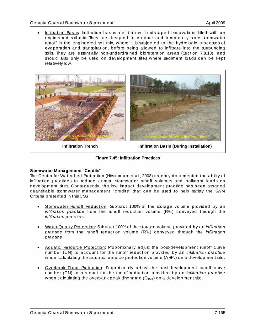
Georgia Coastal Stormwater Supplement April 2009
Infiltration Basins: Infiltration basins are shallow, landscaped excavations filled with an engineered soil mix. They are designed to capture and temporarily store stormwater runoff in the engineered soil mix, where it is subjected to the hydrologic processes of evaporation and transpiration, before being allowed to infiltrate into the surrounding soils. They are essentially non-underdrained bioretention areas (Section 7.8.13), and should also only be used on development sites where sediment loads can be kept relatively low.
Stormwater Management “Credits” The Center for Watershed Protection (Hirschman et al., 2008) recently documented the ability of infiltration practices to reduce annual stormwater runoff volumes and pollutant loads on development sites. Consequently, this low impact development practice has been assigned quantifiable stormwater management “credits” that can be used to help satisfy the SWM Criteria presented in this CSS:
Stormwater Runoff Reduction: Subtract 100% of the storage volume provided by an infiltration practice from the runoff reduction volume (RRv) conveyed through the infiltration practice.
Water Quality Protection: Subtract 100% of the storage volume provided by an infiltration
practice from the runoff reduction volume (RRv) conveyed through the infiltration practice.
Aquatic Resource Protection: Proportionally adjust the post-development runoff curve
number (CN) to account for the runoff reduction provided by an infiltration practice when calculating the aquatic resource protection volume (ARPv) on a development site.
Overbank Flood Protection: Proportionally adjust the post-development runoff curve
number (CN) to account for the runoff reduction provided by an infiltration practice when calculating the overbank peak discharge (Qp25) on a development site.
Figure 7.45: Infiltration Practices
Infiltration Trench Infiltration Basin (During Installation)
(Source: Center for Watershed Protection) (Source: Center for Watershed Protection)
Georgia Coastal Stormwater Supplement 7-165
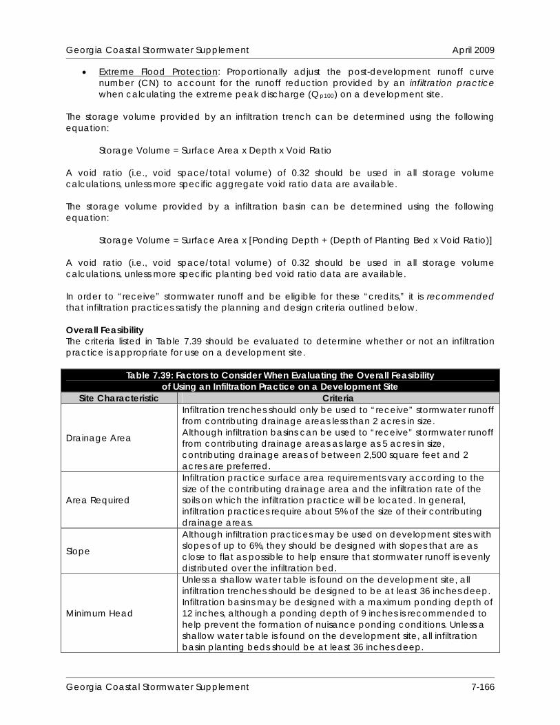
Georgia Coastal Stormwater Supplement April 2009
Extreme Flood Protection: Proportionally adjust the post-development runoff curve number (CN) to account for the runoff reduction provided by an infiltration practice when calculating the extreme peak discharge (Qp100) on a development site.
The storage volume provided by an infiltration trench can be determined using the following equation:
Storage Volume = Surface Area x Depth x Void Ratio A void ratio (i.e., void space/total volume) of 0.32 should be used in all storage volume calculations, unless more specific aggregate void ratio data are available. The storage volume provided by a infiltration basin can be determined using the following equation:
Storage Volume = Surface Area x [Ponding Depth + (Depth of Planting Bed x Void Ratio)] A void ratio (i.e., void space/total volume) of 0.32 should be used in all storage volume calculations, unless more specific planting bed void ratio data are available. In order to “receive” stormwater runoff and be eligible for these “credits,” it is recommended that infiltration practices satisfy the planning and design criteria outlined below. Overall Feasibility The criteria listed in Table 7.39 should be evaluated to determine whether or not an infiltration practice is appropriate for use on a development site.
Table 7.39: Factors to Consider When Evaluating the Overall Feasibility of Using an Infiltration Practice on a Development Site
Site Characteristic Criteria
Drainage Area
Infiltration trenches should only be used to “receive” stormwater runoff from contributing drainage areas less than 2 acres in size. Although infiltration basins can be used to “receive” stormwater runoff from contributing drainage areas as large as 5 acres in size, contributing drainage areas of between 2,500 square feet and 2 acres are preferred.
Area Required
Infiltration practice surface area requirements vary according to the size of the contributing drainage area and the infiltration rate of the soils on which the infiltration practice will be located. In general, infiltration practices require about 5% of the size of their contributing drainage areas.
Slope
Although infiltration practices may be used on development sites with slopes of up to 6%, they should be designed with slopes that are as close to flat as possible to help ensure that stormwater runoff is evenly distributed over the infiltration bed.
Minimum Head
Unless a shallow water table is found on the development site, all infiltration trenches should be designed to be at least 36 inches deep. Infiltration basins may be designed with a maximum ponding depth of 12 inches, although a ponding depth of 9 inches is recommended to help prevent the formation of nuisance ponding conditions. Unless a shallow water table is found on the development site, all infiltration basin planting beds should be at least 36 inches deep.
Georgia Coastal Stormwater Supplement 7-166

Georgia Coastal Stormwater Supplement April 2009
Table 7.39: Factors to Consider When Evaluating the Overall Feasibility of Using an Infiltration Practice on a Development Site
Site Characteristic Criteria Minimum Depth to Water Table 2 feet
Soils
Infiltration practices should be designed to completely drain within 48 hours of the end of a rainfall event. Consequently, infiltration practices generally should not be used on development sites that have soils with infiltration rates of less than 0.25 inches per hour (i.e., hydrologic soil group C and D soils).
Feasibility in Coastal Georgia Several site characteristics commonly encountered in coastal Georgia may present challenges to site planning and design teams that are interested in using infiltration practices to “receive” post-construction stormwater runoff on a development site. Table 7.40 identifies these common site characteristics and describes how they influence the use of infiltration practices on development sites. The table also provides site planning and design teams with some ideas about how they can work around these potential constraints.
Table 7.40: Challenges Associated with Using Infiltration Practices in Coastal Georgia
Site Characteristic How it Influences the Use of Infiltration Practices Potential Solutions
Poorly drained soils, such as hydrologic soil group C and D soils
Reduces the ability of infiltration practices to reduce stormwater runoff rates, volumes and pollutant loads.
Infiltration practices should not be used on development sites that have soils with infiltration rates of less than 0.25 inches per hour (i.e., hydrologic soil group C and D soils).
Use other low impact development practices, such as rainwater harvesting (Section 7.8.12) and underdrained bioretention areas (Section 7.8.13), to “receive” stormwater runoff in these areas.
Well drained soils, such as hydrologic soil group A and B soils
Enhances the ability of infiltration practices to reduce stormwater runoff rates, volumes and pollutant loads, but may allow stormwater pollutants to reach groundwater aquifers with greater ease.
Avoid the use of infiltration-based low impact development practices, including infiltration practices, at stormwater hotspots and in areas known to provide groundwater recharge to water supply aquifers, unless adequate pretreatment is provided upstream of them.
Use bioretention areas (Section 7.8.13) and dry swales (Section 7.8.15) with liners and underdrains at stormwater hotspots and in areas known to provide groundwater recharge to water supply aquifers.
Georgia Coastal Stormwater Supplement 7-167

Georgia Coastal Stormwater Supplement April 2009
Table 7.40: Challenges Associated with Using Infiltration Practices in Coastal Georgia How it Influences the Use Site Characteristic Potential Solutions of Infiltration Practices
Flat terrain Does not influence the use of infiltration practices. In fact, infiltration practices should be designed with slopes that are as close to flat as possible.
Shallow water table
May be difficult to provide 2 feet of clearance between the bottom of the infiltration practice and the top of the water table.
May occasionally cause stormwater runoff to pond in the bottom of the infiltration practice.
Ensure that the distance from the bottom of the infiltration practice to the top of the water table is at least 2 feet.
Reduce the depth of the stone reservoir in infiltration trenches to 18 inches.
Reduce the depth of the planting bed in infiltration basins to 18 inches.
Use stormwater ponds (Section 8.6.1), stormwater wetlands (Section 8.6.2) and wet swales (Section 8.6.6), instead of infiltration practices to intercept and treat stormwater runoff in these areas.
Tidally-influenced drainage system
Does not influence the use of infiltration practices.
Site Applicability Infiltration practices can be used to “receive” stormwater runoff on development sites in rural, suburban and urban areas where the soils are permeable enough and the water table is low enough to provide for the infiltration of stormwater runoff. While infiltration trenches are particularly well-suited for use on small, medium-to-high density development sites, infiltration basins can be used on larger, lower density development sites. Infiltration practices should only be considered for use on development sites where fine sediment (e.g., clay, silt) loads will be relatively low, as high sediment loads will cause them to clog and fail. In addition, infiltration practices should be carefully sited to avoid the potential contamination of water supply aquifers. When compared with other low impact development practices, infiltration practices have a moderate construction cost, a moderate maintenance burden and require a relatively small amount of surface area. Planning and Design Criteria Additional information regarding the planning and design of infiltration practices is provided in Section 8.6.5.
Georgia Coastal Stormwater Supplement 7-168

Georgia Coastal Stormwater Supplement April 2009
7.8.15 Dry Swales Description Dry swales, which may also be classified as a stormwater management practice (Section 8.6.6), are vegetated open channels that are filled with an engineered soil mix and are planted with trees, shrubs and other herbaceous vegetation. They are essentially linear bioretention areas (Section 7.8.13), in that they are designed to capture and temporarily store stormwater runoff in the engineered soil mix, where it is subjected to the hydrologic processes of evaporation and transpiration, before being conveyed back into the storm drain system through an underdrain or allowed to infiltrate into the surrounding soils. (Source: Atlanta Regional Commission, 2001)
STORMWATER MANAGEMENT
“CREDITS”
Runoff Reduction Water Quality Protection Aquatic Resource Protection Overbank Flood Protection Extreme Flood Protection = practice has been assigned quantifiable stormwater management “credits” that can be used to address this SWM Criteria
KEY CONSIDERATIONS
DESIGN CRITERIA:
Dry swales should be designed to accommodate the peak discharge generated by the target runoff reduction rainfall event (e.g., 85th percentile rainfall event)
Dry swales should be designed to able to safely convey the overbank flood protection rainfall event (e.g., 25-year, 24-hour event)
Dry swales may be designed with a slope of between 0.5% and 4%, although a slope of between 1% and 2% is recommended
Dry swales should be designed to completely drain within 48 hours of the end of a rainfall event
BENEFITS:
Helps restore pre-development hydrology on development sites and reduces post-construction stormwater runoff rates, volumes and pollutant loads
Less expensive than traditional drainage (e.g., curb and gutter, storm drain) systems
LIMITATIONS:
Can only be used to “receive” runoff from relatively small drainage areas of 5 acres in size
SITE APPLICABILITY
Rural Use Suburban Use Urban Use
M Construction Cost M Maintenance M Area Required
STORMWATER MANAGEMENT
PRACTICE PERFORMANCE Runoff Reduction 40%/80% - Annual Runoff Volume Varies1 - Runoff Reduction Volume Pollutant Removal2 80% - Total Suspended Solids 50% - Total Phosphorus 50% - Total Nitrogen N/A - Metals 60% - Pathogens 1 = varies according to storage capacity of the dry swale 2 = expected annual pollutant load removal
Georgia Coastal Stormwater Supplement 7-169

Georgia Coastal Stormwater Supplement April 2009
Discussion Dry swales (also known as bioswales), which may also be classified as a stormwater management practice (Section 8.6.6), are vegetated open channels that are filled with an engineered soil mix and are planted with trees, shrubs and other herbaceous vegetation. They are essentially linear bioretention areas (Section 7.8.13), in that they are designed to capture and temporarily store stormwater runoff in the engineered soil mix, where it is subjected to the hydrologic processes of evaporation and transpiration, before being conveyed back into the storm drain system through an underdrain or allowed to infiltrate into the surrounding soils. This allows them to provide measurable reductions in post-construction stormwater runoff rates, volumes and pollutant loads on development sites. Consequently, they can be used to help satisfy the SWM Criteria presented in this CSS. Stormwater Management “Credits” The Center for Watershed Protection (Hirschman et al., 2008) recently documented the ability of dry swales to reduce annual stormwater runoff volumes and pollutant loads on development sites. Consequently, this low impact development practice has been assigned quantifiable stormwater management “credits” that can be used to help satisfy the SWM Criteria presented in this CSS:
Stormwater Runoff Reduction: Subtract 100% of the storage volume provided by a non-underdrained dry swale from the runoff reduction volume (RRv) conveyed through the dry swale. Subtract 50% of the storage volume provided by an underdrained dry swale from the runoff reduction volume (RRv) conveyed through the dry swale.
Water Quality Protection: Subtract 100% of the storage volume provided by a non-
underdrained dry swale from the runoff reduction volume (RRv) conveyed through the dry swale. Subtract 50% of the storage volume provided by an underdrained dry swale from the runoff reduction volume (RRv) conveyed through the dry swale.
Aquatic Resource Protection: Proportionally adjust the post-development runoff curve
number (CN) to account for the runoff reduction provided by a dry swale when calculating the aquatic resource protection volume (ARPv) on a development site.
Overbank Flood Protection: Proportionally adjust the post-development runoff curve
number (CN) to account for the runoff reduction provided by a dry swale when calculating the overbank peak discharge (Qp25) on a development site
Extreme Flood Protection: Proportionally adjust the post-development runoff curve
number (CN) to account for the runoff reduction provided by a dry swale when calculating the extreme peak discharge (Qp100) on a development site
The storage volume provided by a dry swale can be determined using the following equation:
Storage Volume = Surface Area x [Ponding Depth + (Depth of Planting Bed x Void Ratio)] A void ratio (i.e., void space/total volume) of 0.32 should be used in all storage volume calculations, unless more specific planting bed void ratio data are available. In order to “receive” stormwater runoff and be eligible for these “credits,” it is recommended that dry swales satisfy the planning and design criteria outlined below.
Georgia Coastal Stormwater Supplement 7-170

Georgia Coastal Stormwater Supplement April 2009
Overall Feasibility The criteria listed in Table 7.41 should be evaluated to determine whether or not a dry swale is appropriate for use on a development site.
Table 7.41: Factors to Consider When Evaluating the Overall Feasibility of Using a Dry Swale on a Development Site
Site Characteristic Criteria
Drainage Area Dry swales can be used to “receive” stormwater runoff from contributing drainage areas as large as 5 acres in size.
Area Required
Dry swale surface area requirements vary according to the size of the contributing drainage area and the infiltration rate of the soils on which the dry swale will be located. In general, dry swales require about 5-10% of the size of their contributing drainage areas.
Slope Although dry swales may be installed on development sites with slopes of between 0.5% and 4%, it is recommended that they be designed with slopes of between 1% and 2% to help ensure adequate drainage.
Minimum Head Unless a shallow water table is found on the development site, all dry swale planting beds should be at least 30 inches deep.
Minimum Depth to Water Table 2 feet
Soils
Dry swales should be designed to completely drain within 48 hours of the end of a rainfall event. Consequently, non-underdrained dry swales generally should not be used on development sites that have soils with infiltration rates of less than 0.25 inches per hour (i.e., hydrologic soil group C and D soils). Underdrained dry swales may be used to “receive” stormwater runoff on development sites that have soils with infiltration rates of less than 0.25 inches per hour.
Feasibility in Coastal Georgia Several site characteristics commonly encountered in coastal Georgia may present challenges to site planning and design teams that are interested in using dry swales to “receive” post-construction stormwater runoff on a development site. Table 7.42 identifies these common site characteristics and describes how they influence the use of dry swales on development sites. The table also provides site planning and design teams with some ideas about how they can work around these potential constraints.
Table 7.42: Challenges Associated with Using Dry Swales in Coastal Georgia
Site Characteristic How it Influences the Use of Dry Swales Potential Solutions
Poorly drained soils, such as hydrologic soil group C and D soils
Reduces the ability of dry swales to reduce stormwater runoff rates, volumes and pollutant loads.
Use underdrained dry swales to “receive” stormwater runoff in these areas.
Use additional low impact development practices to supplement the stormwater management benefits provided by dry swales in these areas.
Use wet swales (i.e., linear wetland systems) (Section 8.6.6) to intercept, convey and treat stormwater runoff in these areas.
Georgia Coastal Stormwater Supplement 7-171
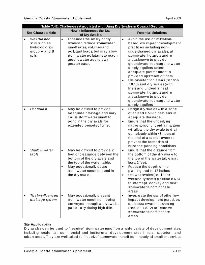
Georgia Coastal Stormwater Supplement April 2009
Table 7.42: Challenges Associated with Using Dry Swales in Coastal Georgia How it Influences the Use Site Characteristic Potential Solutions of Dry Swales
Well drained soils, such as hydrologic soil group A and B soils
Enhances the ability of dry swales to reduce stormwater runoff rates, volumes and pollutant loads, but may allow stormwater pollutants to reach groundwater aquifers with greater ease.
Avoid the use of infiltration-based low impact development practices, including non-underdrained dry swales, at stormwater hotspots and in areas known to provide groundwater recharge to water supply aquifers, unless adequate pretreatment is provided upstream of them.
Use bioretention areas (Section 7.8.13) and dry swales (with liners and underdrains at stormwater hotspots and in areas known to provide groundwater recharge to water supply aquifers.
Flat terrain May be difficult to provide adequate drainage and may cause stormwater runoff to pond in the dry swale for extended periods of time.
Design dry swales with a slope of at least 0.5% to help ensure adequate drainage.
Ensure that the underlying native soils or underdrain system will allow the dry swale to drain completely within 48 hours of the end of a rainfall event to prevent the formation of nuisance ponding conditions.
Shallow water table
May be difficult to provide 2 feet of clearance between the bottom of the dry swale and the top of the water table.
May occasionally cause stormwater runoff to pond in the dry swale.
Ensure that the distance from the bottom of the dry swale to the top of the water table is at least 2 feet.
Reduce the depth of the planting bed to 18 inches.
Use wet swales (i.e., linear wetland systems) (Section 8.6.6) to intercept, convey and treat stormwater runoff in these areas.
Tidally-influenced drainage system
May occasionally prevent stormwater runoff from being conveyed through a dry swale, particularly during high tide.
Investigate the use of other low impact development practices, such as rainwater harvesting (Section 7.8.12) to “receive” stormwater runoff in these areas.
Site Applicability Dry swales can be used to “receive” stormwater runoff on a wide variety of development sites, including residential, commercial and institutional development sites in rural, suburban and urban areas. They are well suited to “receive” stormwater runoff from nearly all small impervious
Georgia Coastal Stormwater Supplement 7-172

Georgia Coastal Stormwater Supplement April 2009
and pervious drainage areas, including local streets and roadways, highways, driveways, small parking areas and disturbed pervious areas (e.g., lawns, parks, community open spaces). When compared with other low impact development practices, dry swales have a moderate construction cost, a moderate maintenance burden and require a relatively small amount of surface area. Planning and Design Criteria Additional information regarding the planning and design of dry swales is provided in Section 8.6.6.
Georgia Coastal Stormwater Supplement 7-173

Georgia Coastal Stormwater Supplement April 2009
Georgia Coastal Stormwater Supplement 7-174
THIS PAGE INTENTIONALLY LEFT BLANK
Georgia Coastal Stormwater Supplement April 2009
References Atlanta Regional Commission (ARC). 2001. Georgia Stormwater Management Manual. Volume
2. Technical Handbook. Atlanta Regional Commission. Atlanta, GA. Available Online: http://www.georgiastormwater.com/.
Carter, T., S. Wenger, R.M. Seymour and D. Stewart. 2007. Runoff Limits Manual. Final Draft.
Etowah Habitat Conservation Plan. Cappiella, K., T. Schueler and T. Wright. 2006a. Urban Watershed Forestry Manual. Part 2:
Conserving and Planting Trees at Development Sites. NA-TP-01-06. US Department of Agriculture. Forest Service. Northeastern Area. State and Private Forestry. Newtown Square, PA. Available Online: http://www.cwp.org/Resource_Library/Special_Resource_Management/forestry.htm.
Cappiella, K., T. Schueler, J. Tomlinson and T. Wright. 2006b. Urban Watershed Forestry Manual.
Part 3: Urban Tree Planting Guide. NA-TP-01-06. US Department of Agriculture. Forest Service. Northeastern Area. State and Private Forestry. Newtown Square, PA. Available Online: http://www.cwp.org/Resource_Library/Special_Resource_Management/forestry.htm.
Center for Watershed Protection (CWP). 1998. Better Site Design: A Handbook for Changing
Development Rules in Your Community. Center for Watershed Protection. Ellicott City, MD. Available Online: http://www.cwp.org/Resource_Library/Controlling_Runoff_and_Discharges/sm.htm.
City of Portland, OR. 2008. Portland Stormwater Management Manual. City of Portland, OR.
Bureau of Environmental Services. Available Online: http://www.portlandonline.com/bes/index.cfm?c=47952.
City of Portland, OR. 2004. Portland Stormwater Management Manual. City of Portland, OR.
Bureau of Environmental Services. Available Online: http://www.portlandonline.com/bes/index.cfm?c=35122&.
Claytor, R. and T. Schueler. 1996. Design of Stormwater Filtering Systems. Prepared for:
Chesapeake Research Consortium, Inc. Center for Watershed Protection. Ellicott City, MD. Available Online: http://www.cwp.org/Resource_Library/Center_Docs/SW/design_swfiltering.pdf.
Faber-Taylor, A. and F.E. Kuo. 2006. “Is Contact With Nature Important for Healthy Child
Development? State of the Evidence.” Children and Their Environments: Learning, Using and Designing Spaces. C. Spencer and M. Blades (Eds.). Cambridge University Press. Cambridge, UK. Available Online: http://www.lhhl.uiuc.edu/all.scientific.articles.htm.
Georgia Department of Natural Resources Wildlife Resources Division (WRD). 2005. A
Comprehensive Wildlife Conservation Strategy for Georgia. Georgia Department of Natural Resources. Wildlife Resources Division. Social Circle, GA. Available Online: http://www1.gadnr.org/cwcs/Documents/strategy.html.
Hirschman, D., K. Collins and T. Schueler. 2008. Runoff Reduction Method. Center for Watershed
Protection. Ellicott City, MD. Available Online: http://www.cwp.org/Resource_Library/Center_Docs/SW/RRTechMemo.pdf.
Georgia Coastal Stormwater Supplement 7-175
Georgia Coastal Stormwater Supplement April 2009
Hunt, W.F. and K.A. Collins. 2008. Permeable Pavement: Research Update and Design Implications. North Carolina Cooperative Extension Service Bulletin. Urban Waterways Series. AGW-588-14. North Carolina State University. Raleigh, NC. Available Online: http://www.bae.ncsu.edu/stormwater/PublicationFiles/PermPave2008.pdf.
Kuo, F.E. 2003. “The Role of Arborculture in a Healthy Social Ecology: Invited Review Article for a
Special Section.” Journal of Arborculture. 29(3): 148-155. Available Online: http://www.lhhl.uiuc.edu/all.scientific.articles.htm.
Kuo, F.E. and W.C. Sullivan. 2001. “Environment and Crime in the Inner City: Does Vegetation
Reduce Crime?” Environment and Behavior. 33(3): 343-367. Available Online: http://www.lhhl.uiuc.edu/all.scientific.articles.htm.
Lantin, A. and Barrett, M. 2005. “Design and Pollutant Reduction of Vegetated Strips and
Swales.” Proceedings of the World Water and Environmental Resources Congress, May 15-19, 2005. American Society of Civil Engineers. Environmental and Water Resources Institute.
Law, N.L., K. Cappiella and M.E. Novotney. 2009. “The Need to Address Both Impervious and
Pervious Surfaces in Urban Watershed and Stormwater Management.” Journal of Hydrologic Engineering. 14(4): 305-308.
MacMullan, E. and S. Reich. 2007. The Economics of Low Impact Development: A Literature
Review. ECONorthwest. Eugene, OR. Available Online: http://www.econw.com/reports/ECONorthwest_Low-Impact-Development-Economics-Literature-Review.pdf.
Maryland Department of the Environment (MDE). 2000. Maryland Stormwater Design Manual.
Maryland Department of the Environment. Water Management Administration. Baltimore, MD. Available Online: http://www.mde.state.md.us/assets/document/sedimentstormwater/mancover.pdf.
Merrill, T.R., Coastal Georgia Regional Development Center (CGRDC) and EMC Engineering
Services, Inc. 2006. Green Growth Guidelines: A Low Impact Development Strategy for Coastal Georgia. Prepared for: Georgia Department of Natural Resources (DNR) Coastal Management Program. Brunswick, GA. Available Online: http://crd.dnr.state.ga.us/content/displaycontent.asp?txtDocument=969.
North Carolina Department of Environment and Natural Resources (NC DENR). 1998. Stormwater
Management Site Planning. North Carolina Department of Environment and Natural Resources. Division of Water Quality. Raleigh, NC. Available Online: http://dem.ehnr.state.nc.us/su/PDF_Files/SW_Documents/Site_Planning_Document.pdf.
North Carolina State University (NCSU). 2008. “Rainwater Harvesting at NCSU.” North Carolina
State University. Department of Biological and Agricultural Engineering. Stormwater Engineering Group. http://www.bae.ncsu.edu/topic/waterharvesting/. Accessed: July 28, 2008.
U.S. Environmental Protection Agency (US EPA). 2008. “Environmental Benefits of Green
Infrastructure.” Managing Wet Weather with Green Infrastructure. http://cfpub.epa.gov/npdes/greeninfrastructure/information.cfm#enviroben. Accessed: June 27, 2008.
Georgia Coastal Stormwater Supplement 7-176
Georgia Coastal Stormwater Supplement April 2009
Rupp, G. 1998. Rainwater Harvesting Systems for Montana. Montana State University Extension Service. Bozeman, MT. Available Online: http://www.montana.edu/wwwpb/pubs/mt9707.html.
Schueler, T. 2000. “The Compaction of Urban Soils.” The Practice of Watershed Protection. T.
Schueler and H. Holland (Eds.). Center for Watershed Protection. Ellicott City, MD. Schueler, T. 1995. Site Planning for Urban Stream Protection. Prepared for: Metropolitan
Washington Council of Governments. Center for Watershed Protection. Ellicott City, MD. Sullivan, W.C., F.E. Kuo and S.F. DePooter. 2003. “The Fruit of Urban Nature: Vital Neighborhood
Spaces.” Environment and Behavior. 36(5): 678-700. Available Online: http://www.lhhl.uiuc.edu/all.scientific.articles.htm.
Taylor, A.F., A. Wiley, F.E. Kuo and W.C. Sullivan. 1998. “Growing Up in the Inner City: Green
Spaces as Places to Grow.” Environment and Behavior. 30(1): 3-27. Available Online: http://www.lhhl.uiuc.edu/all.scientific.articles.htm.
Texas Water Development Board (TWDB). 2005. The Texas Manual on Rainwater Harvesting. 3rd
Edition. Texas Water Development Board. Austin, TX. Available Online: http://www.twdb.state.tx.us/publications/reports/RainwaterHarvestingManual_3rdedition
.pdf. U.S. Environmental Protection Agency (US EPA). 2008. “Environmental Benefits of Green
Infrastructure.” Managing Wet Weather with Green Infrastructure. http://cfpub.epa.gov/npdes/greeninfrastructure/information.cfm#enviroben. Accessed: June 27, 2008.
U.S. Environmental Protection Agency (US EPA). 2007. Reducing Stormwater Costs Through Low
Impact Development (LID) Strategies and Practices. EPA 841-F-07-006. U.S. Environmental Protection Agency. Washington, DC. Available Online: http://www.epa.gov/owow/nps/lid/costs07/.
Jones, M.P. and W.F. Hunt. 2008. Rainwater Harvesting: Guidance for Homeowners. North
Carolina Cooperative Extension Service Bulletin. Urban Waterways Series. AGW-588-11. North Carolina State University. Raleigh, NC. Available Online: http://www.bae.ncsu.edu/stormwater/PublicationFiles/WaterHarvestHome2008.pdf.
Winer-Skonovd, R., D. Hirschman, H.Y. Kwon and C. Swann. 2006. Synthesis of Existing Cost
Information for LID vs. Conventional Practices. Center for Watershed Protection. Ellicott City, MD.
Georgia Coastal Stormwater Supplement 7-177

Georgia Coastal Stormwater Supplement April 2009
Georgia Coastal Stormwater Supplement 7-178
THIS PAGE INTENTIONALLY LEFT BLANK
Related Documents