663 FIBER SENSORS LASER SENSORS PHOTOELECTRIC SENSORS MICRO PHOTOELECTRIC SENSORS AREA SENSORS SAFETY LIGHT CURTAINS / SAFETY COMPONENTS PRESSURE / FLOW SENSORS INDUCTIVE PROXIMITY SENSORS PARTICULAR USE SENSORS SENSOR OPTIONS SIMPLE WIRE-SAVING UNITS WIRE-SAVING SYSTEMS MEASUREMENT SENSORS STATIC CONTROL DEVICES LASER MARKERS PLC HUMAN MACHINE INTERFACES ENERGY MANAGEMENT SOLUTIONS FA COMPONENTS MACHINE VISION SYSTEMS UV CURING SYSTEMS Selection Guide Safety Light Curtains Safety Control Units Safety Components SF-C21 SF-C10 Related Information Exclusive Control Unit for Safety Light Curtain SF-C10 SERIES Less setup time for safety circuits Quick-connection Easy setup requiring no torque control A spring method is used for the terminal blocks for connections other than to the safety light curtain. There is no need to control tightening torques for these terminal blocks. Connecting to the safety light curtain is done using plug-in connections, which shortens setup and replacement time. Removable terminal blocks reduce maintenance time Removable terminal blocks are used. This reduces the work required for reconnecting wiring during maintenance. Lead wire Flat-tipped screwdriver Release button Lead wire insertion hole Ferrule (sleeve) terminal (Please arrange separately.) Uses a spring method! Metal enclosure with a IP65 protective structure The strong metal enclosure has a built-in safety relay. It has an IP65 protective structure, so that it can be set up individually without needing to be inserted into a control panel. Slim design 22.5 mm 0.886 in thickness, so can be inserted even into narrow spaces inside panels. Removable! IP65 Metal enclosure The wiring with the safety light curtain is connector connection. Slim 22.5 mm 0.886 in Spring-type terminal block No torque control needed Plug-in type control unit SF-C11 / SF-C14EX(-01) Robust type control unit SF-C12 Slim type control unit SF-C13 ■ General terms and conditions ............. F-3 ■ SF4D............................................. P.459~ ■ General precautions ..................... P.1595 ■ Korea’s S-mark ............................. P.1602 Certified Listing Certified (SF-C11/C13 only) panasonic.net/id/pidsx/global Category 4 PLe SIL3 The control category differs depending on the configuration and wiring of the external circuit. ■ SF4B / SF4B-G ............................ P.501~ ■ SF4C / SF2B ..................P.577~ / P.603~

Welcome message from author
This document is posted to help you gain knowledge. Please leave a comment to let me know what you think about it! Share it to your friends and learn new things together.
Transcript

663
FIBERSENSORS
LASERSENSORS
PHOTOELECTRICSENSORS
MICROPHOTOELECTRIC
SENSORS
AREASENSORS
SAFETY LIGHT CURTAINS /
SAFETY COMPONENTSPRESSURE /
FLOWSENSORS
INDUCTIVEPROXIMITY
SENSORS
PARTICULARUSE SENSORS
SENSOROPTIONS
SIMPLEWIRE-SAVING
UNITS
WIRE-SAVING SYSTEMS
MEASUREMENTSENSORS
STATIC CONTROL DEVICES
LASERMARKERS
PLC
HUMAN MACHINE INTERFACES
ENERGY MANAGEMENT
SOLUTIONS
FA COMPONENTS
MACHINE VISION SYSTEMS
UV CURING SYSTEMS
Selection Guide
Safety Light Curtains
Safety Control Units
Safety Components
SF-C21
SF-C10
Related Information
Exclusive Control Unit for Safety Light Curtain
SF-C10 SERIES
Less setup time for safety circuits
Quick-connection Easy setup requiring no torque controlA spring method is used for the terminal blocks for connections other than to the safety light curtain. There is no need to control tightening torques for these terminal blocks.
Connecting to the safety light curtain is done using plug-in connections, which shortens setup and replacement time.
Removable terminal blocks reduce maintenance timeRemovable terminal blocks are used. This reduces the work required for reconnecting wiring during maintenance.
Lead wireFlat-tipped screwdriver
Release button
Lead wire insertion hole
Ferrule (sleeve) terminal(Please arrange separately.)
Uses a spring method!
Metal enclosure with a IP65 protective structureThe strong metal enclosure has a built-in safety relay. It has an IP65 protective structure, so that it can be set up individually without needing to be inserted into a control panel.
Slim design22.5 mm 0.886 in thickness, so can be inserted even into narrow spaces inside panels.
Removable!
IP65 Metal enclosure
The wiring with the safety light curtain is connector connection.
Slim22.5 mm0.886 in
Spring-type terminal blockNo torque control needed
Plug-in type control unit SF-C11 / SF-C14EX(-01)
Robust type control unit SF-C12 Slim type control unit SF-C13
General terms and conditions ............. F-3 SF4D............................................. P.459~
General precautions ..................... P.1595 Korea’s S-mark ............................. P.1602
Certified
Listing
Certified (SF-C11/C13 only)
panasonic.net/id/pidsx/globalCategory 4 PLe SIL3
The control category differs depending on the configuration and wiring of the external circuit.
SF4B / SF4B-G ............................ P.501~ SF4C / SF2B ..................P.577~ / P.603~

Exclusive Control Unit for Safety Light Curtain SF-C10 SERIES 664
FIBERSENSORS
LASERSENSORS
PHOTOELECTRICSENSORS
MICROPHOTOELECTRICSENSORS
AREASENSORS
SAFETY LIGHT CURTAINS /SAFETY COMPONENTSPRESSURE / FLOWSENSORSINDUCTIVEPROXIMITYSENSORS
PARTICULARUSE SENSORS
SENSOROPTIONS
SIMPLEWIRE-SAVINGUNITS
WIRE-SAVING SYSTEMS
MEASUREMENTSENSORS
STATIC CONTROL DEVICES
LASERMARKERS
PLC
HUMAN MACHINE INTERFACES
ENERGY MANAGEMENT SOLUTIONS
FA COMPONENTS
MACHINE VISION SYSTEMS
UV CURING SYSTEMS
Selection GuideSafety Light CurtainsSafety Control UnitsSafety Components
SF-C21
SF-C10
The method used to build the safety circuit is selectableIt is possible to build muting control circuits using a stand-alone safety light curtain from the SF4B / SF4B-G series. The SF-C14EX(-01) application expansion unit allows the safety light curtain, muting sensors and muting lamps to be connected together directly, so that muting control circuits can be built very easily.
Buildingmethod Using SF4B series functions
Motor, etc.
External devices(Force-guided relay, etc.)
Mutingsensors
Mutinglamps
Low cost!Saves space!
No safety relay unit needed
Muting control
Safety output
Terminal blocksSF4Bseries Safety light curtain connector connection.
Terminal blocks for peripheral circuits available.
Muting sensors
Muting lamps
Building method Using the SF-C14EX(-01) internal circuits
Motor, etc.
External devices (Force-guided relay, etc.)
Less wiring!
Reduced maintenance!
SF-C14EX(-01)
Exclusive mating cable for SF-C14EX(-01)
SF4B series
Muting control
Safety output
Three safety circuit systems packaged into a single unit!Three safety circuit systems 1 Safety light curtain output circuit, 2 Muting control circuit, and 3 Emergency stop circuit are packaged into a single unit. Functions that require multiple safety relay units and muting control units can be concentrated into a single unit, which results in large space savings, less wiring and less installation work.
High-speed response 14 ms (Including safety light curtain)High-speed response has been achieved due to the adoption of the semiconductor output. Avoids the response delays that occur when using more than one safety relay unit, and greatly reduces the safety light curtain safety distance and improves ease of working. Of course, it is not necessary to exchange the safety relays within the unit anymore, which contributes to the reduction of running cost.
20 ms 35 ms10 ms 14 ms
SF-C14EX(-01)Previous model
SF-C14EX(-01)
Previous model
Including safety light curtain response time
High response speed of 14 ms!Greatly reduced safety distance!Muting sensor Muting sensor Emergency stop button Safety light curtain Emergency stop button SF4B series
SF-C14EX(-01)Customer's logical connection circuit
Motor Motor
Saves space!
Less wiring!
Less construction!
Furthermore, due to the semiconductor output,
Safety light curtain output circuitEmergency stop circuit
Safety relay unit
Muting unit Safety relay unit
Total 14 ms!
Relay replacement is not required!
Customer's logical connection circuit
External contactor (Force-guided relay, etc.)
External contactor (Force-guided relay, etc.)
1 2 3
Muting control circuit
1
1
1
1
1 1
2
2
2
2
2 2
3
3
3
3
3 3
Building of muting control circuits is easy SF-C14EX(-01)
Both safety and productivity can be obtained by stopping only one part of the device SF-C14EX(-01)

665 Exclusive Control Unit for Safety Light Curtain SF-C10 SERIES
FIBERSENSORS
LASERSENSORS
PHOTOELECTRICSENSORS
MICROPHOTOELECTRIC
SENSORS
AREASENSORS
SAFETY LIGHT CURTAINS /
SAFETY COMPONENTSPRESSURE /
FLOWSENSORS
INDUCTIVEPROXIMITY
SENSORS
PARTICULARUSE SENSORS
SENSOROPTIONS
SIMPLEWIRE-SAVING
UNITS
WIRE-SAVING SYSTEMS
MEASUREMENTSENSORS
STATIC CONTROL DEVICES
LASERMARKERS
PLC
HUMAN MACHINE INTERFACES
ENERGY MANAGEMENT
SOLUTIONS
FA COMPONENTS
MACHINE VISION SYSTEMS
UV CURING SYSTEMS
Selection Guide
Safety Light Curtains
Safety Control Units
Safety Components
SF-C21
SF-C10
Motors that use muting control and those that do not use it can be controlled independently!Controls the motors that use muting control (robots) and the motors that do not use muting control (turntables) with a single unit.When the workpiece comes in, the turntable can be stopped and the robot can keep operating condition, to protect the safety of the operator and to maintain productivity.
output systems using only a single unit!SF-C14EX(-01) controls three safety
Emergency stop button Turntable Motor not using muting
SF4B series
Limit switch For muting input
Robot Motor using muting
1 3 2
Robot Motor using muting
Safety circuit 1 : Linked to safety light curtain beam received / interrupted status (partial stop)
When the safety light curtain is interrupted (when an workpiece enters or a person intrudes), this circuit switches off (open) the safety output and stops the turntable.
Safety circuit 2 : Linked to muting control (partial stop)
If an workpiece enters when the turntable has stopped normally, (muting conditions are achieved), this circuit allows the robot to operate.If an workpiece enters while the turntable is turning (muting conditions are not achieved), this circuit switches off (open) the safety output and stops the robot.
Safety circuit 3 : Linked to emergency stop input (all stop)
When the emergency stop button is pressed, this circuit switches off (open) the safety output and stops all equipment (turntable and robot).
Equipped with blown lamp output for muting lampIf a lamp in one of the two muting lamps that are connected to the unit blows, a warning is output. It is possible to replace the lamp before both lamps blow and the equipment stops. In addition, auxiliary output that is linked to the muting function, override function and safety light curtain control output is also available.
Equipped with a digital indicator so that error details can be understood at a glance!
Function Operation
Auxiliary output 1 Muting output ON when the muting
function is invalid
Auxiliary output 2 Override output ON when the override
function is invalid
Auxiliary output 3 Blown lamp output ON when the muting
lamp is normal
Auxiliary output 4
Safety light curtainauxiliary output
ON when the safety light curtain is in light interrupted condition
If a problem should occur, the same output (OFF signal) as when the object was detected is maintained in order to ensure safety, and the details of the error appear on the digital display.
NPN PNP NPN PNP
Polarity selection switch
Supports both PNP and NPN polaritiesA single model can be used for PNP/NPN input switching, reducing the number of parts that need to be registered.
All Models
Three safety circuit systems can be controlled independently so that equipment can be stopped all together or partially SF-C14EX(-01)

Exclusive Control Unit for Safety Light Curtain SF-C10 SERIES 666
FIBERSENSORS
LASERSENSORS
PHOTO-ELECTRICSENSORSMICROPHOTO-ELECTRICSENSORS
AREASENSORS
SAFETY LIGHT CURTAINS /SAFETY COMPONENTSPRESSURE / FLOWSENSORS
INDUCTIVEPROXIMITYSENSORS
PARTICULARUSE SENSORS
SENSOROPTIONS
SIMPLEWIRE-SAVINGUNITS
WIRE-SAVING SYSTEMS
MEASURE-MENTSENSORS
STATIC CONTROL DEVICES
LASERMARKERS
PLC
HUMAN MACHINE INTERFACES
ENERGY MANAGEMENT SOLUTIONS
FA COMPONENTS
MACHINE VISION SYSTEMS
UV CURING SYSTEMS
Selection GuideSafety Light CurtainsSafety Control UnitsSafety Components
SF-C21
SF-C10
ORDER GUIDE
Note: Refer to SF4B / SF4B-G series pages (p.512~) and SF2B series pages (p.608) for the applicable cable.
SF-C12 spare relay setA set of spare relays (2 safety relays and 1 removal tool) is available for the safety relay that is built into the SF-C12.Model No.: SF-C12-RY
Designation Appearance Model No. Applicable cable (Note) Description
Connector connection type control unit
SF-C11
Safety light curtain connection cable:SFB-CB
(For SF4B series)SF2B-CB
(For SF2B series)Extension cable: SFB-CCJ10
Use 8-core cable with connector to connect to the safety light curtain.Compatible with up to Control Category 4.Interference prevention wires and muting function cannot be used.
Robust typecontrol unit SF-C12
Safety light curtain connection cable: SFB-CB05-MU
Extension cable: SFB-CCJ10-MU
Use 12-core cable with connector to connect to the safety light curtain. Interference prevention wires can be used.Compatible with up to Control Category 4.Muting function cannot be used.
Slim typecontrol unit SF-C13
Safety light curtain connection cable:SFB-CCB(-MU)
(For SF4B series)SF2B-CCB
(For SF2B series)Extension cable: SFB-CC(-MU)
Use a discrete wire cable to connect to the safety light curtain. Muting function and interference prevention wires can be used.Compatible with up to Control Category 4.
Application expansion unit for SF4B / SF4B-G series
SF-C14EXSafety light curtain connection cable:
SFB-CB-EXExtension cable: SFB-CCJ10
The muting control function and emergency stop input expand the applications of the safety light curtains. Use exclusive cable to connect to the safety light curtain.Compatible with up to Control Category 4.The handy-controller SFB-HC (optional) cannot be used with SF-C14EX-01.
Hand
y-con
troller
no
n-com
patibl
e type
SF-C14EX-01
667 Exclusive Control Unit for Safety Light Curtain SF-C10 SERIES
FIBERSENSORS
LASERSENSORS
PHOTO-ELECTRICSENSORS
MICROPHOTO-
ELECTRICSENSORS
AREASENSORS
SAFETY LIGHT CURTAINS /
SAFETY COMPONENTSPRESSURE /
FLOWSENSORS
INDUCTIVEPROXIMITY
SENSORS
PARTICULARUSE
SENSORS
SENSOROPTIONS
SIMPLEWIRE-SAVING
UNITS
WIRE-SAVING SYSTEMS
MEASURE-MENT
SENSORS
STATIC CONTROL DEVICES
LASERMARKERS
PLC
HUMAN MACHINE
INTERFACES
ENERGY MANAGEMENT
SOLUTIONS
FA COMPONENTS
MACHINE VISION
SYSTEMS
UV CURING
SYSTEMS
Selection Guide
Safety Light Curtains
Safety Control Units
Safety Components
SF-C21
SF-C10
SPECIFICATIONS
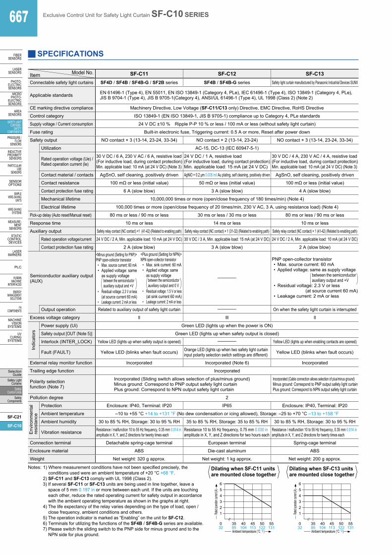
Model No.Item SF-C11 SF-C12 SF-C13Connectable safety light curtains SF4D / SF4B / SF4B-G / SF2B series SF4B / SF4B-G series Safety light curtain manufactured by Panasonic Industrial Devices SUNX
Applicable standards EN 61496-1 (Type 4), EN 55011, EN ISO 13849-1 (Category 4, PLe), IEC 61496-1 (Type 4), ISO 13849-1 (Category 4, PLe), JIS B 9704-1 (Type 4), JIS B 9705-1(Category 4), ANSI/UL 61496-1 (Type 4), UL 1998 (Class 2) (Note 2)
CE marking directive compliance Machinery Directive, Low Voltage (SF-C11/C13 only) Directive, EMC Directive, RoHS Directive
Control category ISO 13849-1 (EN ISO 13849-1, JIS B 9705-1) compliance up to Category 4, PLe standards
Supply voltage / Current consumption 24 V DC ±10 % Ripple P-P 10 % or less / 100 mA or less (without safety light curtain)
Fuse rating Built-in electronic fuse, Triggering current: 0.5 A or more, Reset after power down
Safety output NO contact × 3 (13-14, 23-24, 33-34) NO contact × 2 (13-14, 23-24) NO contact × 3 (13-14, 23-24, 33-34)
Utilization AC-15, DC-13 (IEC 60947-5-1)
Rated operation voltage (Ue) /Rated operation current (le)
30 V DC / 6 A, 230 V AC / 6 A, resistive load(For inductive load, during contact protection)Min. applicable load: 10 mA (at 24 V DC) (Note 3)
24 V DC / 1 A, resistive load(For inductive load, during contact protection)Min. applicable load: 15 mA (at 24 V DC)
30 V DC / 4 A, 230 V AC / 4 A, resistive load(For inductive load, during contact protection)Min. applicable load: 10 mA (at 24 V DC) (Note 3)
Contact material / contacts AgSnO, self cleaning, positively driven AgNiO + 0.2 µm 0.008 mil Au plating, self cleaning, positively driven AgSnO, self cleaning, positively driven
Contact resistance 100 mΩ or less (initial value) 50 mΩ or less (initial value) 100 mΩ or less (initial value)
Contact protection fuse rating 6 A (slow blow) 3 A (slow blow) 4 A (slow blow)
Mechanical lifetime 10,000,000 times or more (open/close frequency of 180 times/min) (Note 4)
Electrical lifetime 100,000 times or more (open/close frequency of 20 times/min, 230 V AC, 3 A, using resistance load) (Note 4)
Pick-up delay (Auto reset/Manual reset) 80 ms or less / 90 ms or less 30 ms or less / 30 ms or less 80 ms or less / 90 ms or less
Response time 10 ms or less 14 ms or less 10 ms or less
Auxiliary output Safety relay contact (NC contact) ×1 (41-42) (Related to enabling path) Safety relay contact (NC contact) × 1 (31-32) (Related to enabling path) Safety relay contact (NC contact) × 1 (41-42) (Related to enabling path)
Rated operation voltage/current 24 V DC / 2 A, Min. applicable load: 10 mA (at 24 V DC) 30 V DC / 3 A, Min. applicable load: 15 mA (at 24 V DC) 24 V DC / 2 A, Min. applicable load: 10 mA (at 24 V DC)
Contact protection fuse rating 2 A (slow blow) 3 A (slow blow) 2 A (slow blow)
Semiconductor auxiliary output(AUX)
<Minus ground (Setting for PNP)>PNP open-collector transistor
• Max. source current: 60 mA• Applied voltage: same
as supply voltagebetween the semiconductorauxiliary output and +V
• Residual voltage: 2.3 V or less (at source current 60 mA)
• Leakage current: 2 mA or less
<Plus ground (Setting for NPN)>NPN open-collector transistor
• Max. sink current: 60 mA• Applied voltage: same
as supply voltagebetween the semiconductorauxiliary output and 0 V
• Residual voltage: 1.5 V or less (at sink current 60 mA)
• Leakage current: 2 mA or less
–
PNP open-collector transistor• Max. source current: 60 mA• Applied voltage: same as supply voltage
between the semiconductorauxiliary output and +V
• Residual voltage: 2.3 V or less(at source current 60 mA)
• Leakage current: 2 mA or less
Output operation Related to auxiliary output of safety light curtain – On when the safety light curtain is interrupted
Excess voltage category ll lll ll
Indi
cato
rs
Power supply (Ui) Green LED (lights up when the power is ON)
Safety output [OUT (Note 5)] Green LED (lights up when safety output is closed)
Interlock (INTER_LOCK) Yellow LED (lights up when safety output is opened) – Yellow LED (lights up when enabling contacts are opened)
Fault (FAULT) Yellow LED (blinks when fault occurs) Orange LED (lights up when two safety light curtain input polarity selection switch settings are different) Yellow LED (blinks when fault occurs)
External relay monitor function Incorporated Incorporated (Note 6) Incorporated
Trailing edge function Incorporated
Polarity selection function (Note 7)
Incorporated (Sliding switch allows selection of plus/minus ground)Minus ground: Correspond to PNP output safety light curtainPlus ground: Correspond to NPN output safety light curtain
Incorporated (Cable connection allows selection of plus/minus ground)Minus ground: Correspond to PNP output safety light curtainPlus ground: Correspond to NPN output safety light curtain
Pollution degree 2
Env
ironm
enta
lre
sist
ance
Protection Enclosure: IP40, Terminal: IP20 IP65 Enclosure: IP40, Terminal: IP20
Ambient temperature –10 to +55 °C +14 to +131 °F (No dew condensation or icing allowed), Storage: –25 to +70 °C –13 to +158 °F
Ambient humidity 30 to 85 % RH, Storage: 30 to 95 % RH 35 to 85 % RH, Storage: 35 to 85 % RH 30 to 85 % RH, Storage: 30 to 95 % RH
Vibration resistance Resistance / malfunction 10 to 55 Hz frequency, 0.35 mm 0.014 in amplitude in X, Y, and Z directions for twenty times each
Resistance 10 to 55 Hz frequency, 0.75 mm 0.030 in amplitude in X, Y, and Z directions for two hours each
Resistance / malfunction 10 to 55 Hz frequency, 0.35 mm 0.014 in amplitude in X, Y, and Z directions for twenty times each
Connection terminal Detachable spring-cage terminal European terminal Spring-cage terminal
Enclosure material ABS Die-cast aluminum ABS
Weight Net weight: 320 g approx. Net weight: 1 kg approx. Net weight: 200 g approx.
Notes: 1) Where measurement conditions have not been specified precisely, the conditions used were an ambient temperature of +20 °C +68 °F.
2) SF-C11 and SF-C13 comply with UL 1998 (Class 2). 3) If several SF-C11 or SF-C13 units are being used in line together, leave a
space of 5 mm 0.197 in or more between each unit. If the units are touching each other, reduce the rated operating current for safety output in accordance with the ambient operating temperature as shown in the graphs at right.
4) The life expectancy of the relay varies depending on the type of load, open / close frequency, ambient conditions and others.
5) The operation indicator is marked as “Enabling” on the unit for SF-C12. 6) Terminals for utilizing the functions of the SF4B / SF4B-G series are available. 7) Please switch the sliding switch to the PNP side for minus ground and to the
NPN side for plus ground.Ambient temperature (°C °F)
032
123456
3595
40104
45113
50122
55131
Rated
opera
tion cu
rrent (A
)
123456
Ambient temperature (°C °F)
032
3595
40104
45113
50122
55131
Rated
opera
tion cu
rrent (A
)
Dilating when SF-C11 units are mounted close together
Dilating when SF-C13 units are mounted close together

Exclusive Control Unit for Safety Light Curtain SF-C10 SERIES 668
FIBERSENSORS
LASERSENSORS
PHOTO-ELECTRICSENSORSMICROPHOTO-ELECTRICSENSORS
AREASENSORS
SAFETY LIGHT CURTAINS /SAFETY COMPONENTSPRESSURE / FLOWSENSORS
INDUCTIVEPROXIMITYSENSORS
PARTICULARUSE SENSORS
SENSOROPTIONS
SIMPLEWIRE-SAVINGUNITS
WIRE-SAVING SYSTEMS
MEASURE-MENTSENSORS
STATIC CONTROL DEVICES
LASERMARKERS
PLC
HUMAN MACHINE INTERFACES
ENERGY MANAGEMENT SOLUTIONS
FA COMPONENTS
MACHINE VISION SYSTEMS
UV CURING SYSTEMS
Selection GuideSafety Light CurtainsSafety Control UnitsSafety Components
SF-C21
SF-C10
Model No.Item SF-C14EX(-01) (Note 2)
Connectable safety light curtains SF4B / SF4B-G series
Applicable standards IEC 61496-1 (Type 4), EN 55011, EN ISO 13849-1 (Category 4, PLe), IEC 61496 (Type 4), ISO 13849-1 (Category 4, PLe), JIS B 9704-1 (Type 4), JIS B 9705-1 (Category 4, PLe), ANSI/UL 61496-1 (Type 4), UL 1998 (Class 2)
CE marking directive compliance Machinery Directive, EMC Directive, RoHS Directive
Control category ISO 13849-1 (EN ISO 13849-1, JIS B 9705-1) compliance up to Category 4, PLe standards
Supply voltage 24 V DC ±10 % Ripple P-P 10 % or less
Current consumption 0.2 A or less (Excluding safety light curtain and other external connecting device)
Safety outputsSafety output 1Safety output 2Safety output 3
PNP open-collector transistor 2 outputs × 3 or NPN open-collector transistor 2 outputs × 3 (selectable using a slider switch)<When PNP output is selected>
• Maximum source current: 200 mA • Applied voltage: same as supply voltage
(between the safety output and +V)• Residual voltage: 2 V or less (at 200 mA source current)
<When NPN output is selected>• Maximum sink current: 200 mA • Applied voltage: same as supply voltage
(between the safety output and 0 V)• Residual voltage: 2 V or less (at 200 mA sink current)
Operation mode(Output operation)
Safety output 1: ON when the safety light curtain is in light receiving condition, OFF when the safety light curtain is in light interrupted condition (Note 3)Safety output 2: ON when the safety light curtain is in light receiving condition or the muting function is valid
OFF when the safety light curtain is in light interrupted condition and the muting function is invalid (Note 3)Safety output 3: ON when the emergency stop is invalid, OFF when the emergency stop is valid
Protection circuit(Short-circuit protection) Incorporated
Response time OFF response: 14 ms or less (Safety output 1 and 2: including the response time of the safety light curtain)ON response: 90 ms or less (auto-reset) / 140 ms or less (manual reset) (Note 4)
Auxiliary outputsAuxiliary output 1Auxiliary output 2Auxiliary output 3Auxiliary output 4 (Note 5)
PNP open-collector transistor × 3 or NPN open-collector transistor × 3 (selectable using a slider switch)<When PNP output is selected>
• Maximum source current: 60 mA • Applied voltage: same as supply voltage
(between the auxiliary output and +V)• Residual voltage: 2 V or less (at 60 mA source current)
<When NPN output is selected>• Maximum sink current: 60 mA • Applied voltage: same as supply voltage
(between the auxiliary output and 0 V)• Residual voltage: 2 V or less (at 60 mA sink current)
Operation mode(Output operation)
Auxiliary output 1: ON when the muting function is invalid, OFF when the muting function is validAuxiliary output 2: ON when the override function is invalid, OFF when the override function is validAuxiliary output 3: ON when the muting lamp is normal, OFF when the muting lamp is errorAuxiliary output 4: ON when the safety light curtain is in light interrupted condition, OFF when the safety light curtain is in light
receiving condition (Note 5)
Protection circuit(Short-circuit protection) Incorporated
Muting lamp output Applicable muting lamp: 24 V DC, 3.6 to 30 W (L1, L2 of each unit)
Protection circuit(Short-circuit protection) Incorporated
PFHD (Note 6) 1.66 × 10⁻¹⁰
MTTFD (Note 6) 100 years or more
Env
ironm
enta
l res
ista
nce Protection Enclosure: IP40, Terminal: IP20
Ambient temperature –10 to +55 °C +14 to +131 °F (No dew condensation or icing allowed), Storage: –25 to +70 °C –13 to +158 °F
Ambient humidity 30 to 85 % RH, Storage: 30 to 95 % RH
Dielectric strength voltage 1,000 V AC for one min. between all supply terminals connected together and enclosure
Insulation resistance 20 MΩ, or more, with 500 V DC megger between all supply terminals connected together and enclosure
Vibration resistance 10 to 55 Hz frequency, 0.35 mm 0.014 in double amplitude in X, Y and Z directions for two hours each
Shock resistance 30 G acceleration in X, Y and Z directions three times each
Material Enclosure: ABS
Connection terminal Detachable spring-cage terminal
Weight Net weight: 250 g approx.
SPECIFICATIONS
Notes: 1) Where measurement conditions have not been specified precisely, the conditions used were an ambient temperature of +20 °C +68 °F.2) The handy-controller SFB-HC (optional) cannot be used with SF-C14EX-01.3) Both safety output 1 and 2 are OFF when the emergency stop is valid regardless of whether the safety light curtain is in the light receiving or light
interrupted condition.4) The auto-reset cannot be used with safety output 3.5) The auxiliary output incorporated in the SF4B / SF4B-G series is output.6) PFHD: Probability of dangerous failure per hour, MTTFD: Mean time to dangerous failure (in years)

669 Exclusive Control Unit for Safety Light Curtain SF-C10 SERIES
FIBERSENSORS
LASERSENSORS
PHOTO-ELECTRICSENSORS
MICROPHOTO-
ELECTRICSENSORS
AREASENSORS
SAFETY LIGHT CURTAINS /
SAFETY COMPONENTSPRESSURE /
FLOWSENSORS
INDUCTIVEPROXIMITY
SENSORS
PARTICULARUSE
SENSORS
SENSOROPTIONS
SIMPLEWIRE-SAVING
UNITS
WIRE-SAVING SYSTEMS
MEASURE-MENT
SENSORS
STATIC CONTROL DEVICES
LASERMARKERS
PLC
HUMAN MACHINE
INTERFACES
ENERGY MANAGEMENT
SOLUTIONS
FA COMPONENTS
MACHINE VISION
SYSTEMS
UV CURING
SYSTEMS
Selection Guide
Safety Light Curtains
Safety Control Units
Safety Components
SF-C21
SF-C10
SAFETY LIGHT CURTAIN WIRING DIAGRAMSWiring diagram of SF-C11 and SF4B / SF4B-G series or SF2B series (Control Category 4 or 2)
For PNP output (minus ground)• Set the safety light curtain input polarity selection switch
to the PNP side and ground the 0 V line.
3M
+24 V DC
F
A1
A2
0 VF.G.
T2 T1
K1
K2
KB
KB
KAKA
N
14 24 34 42L1 L2 L3
13 23 33 41X1 X2 A B
AUX
L1
NPNPNPSF-C11 control circuit
Receiver sideconnector
Emitter sideconnector
Ui
OUT FAULTINTER_LOCK
FUSE1 FUSE2RESET(Note 1)(Note 2)
TEST(Note 3)
Safety light curtain input polarity selection switch
KA, KB: Magnet contactor
X3(Note 1)
Notes: 1) The above diagram is when using manual reset. If automatic reset is used, disconnect the lead from X2 and connect it to X3. In this case, a reset (RESET) button is not needed.
2) Use a momentary-type switch as the reset (RESET) button.3) Emission halt occurs when the test (TEST) button is open, and emission occurs
when the test (TEST) button is short-circuited. If not using the test (TEST) button, short-circuit T1 and T2. However, in case of SF2B series, use a test rod or similar to interrupt the light in order to carry out self-diagnosis separately.
For NPN output (plus ground)• In the above
diagram, set the safety light curtain input polarity selection switch to the NPN side and ground the + side.
Wiring diagram of SF-C12 and SF4B / SF4B-G series (Control Category 4)
For PNP output (minus ground)• Set the two safety light curtain input polarity selection switches
to the PNP side and connect the F.G. terminal to the 0 V line.
Interference prevention wire
Safety output Power input24 V DC ±10 %
Auxiliary output
Emitter side connector
Receiver side connector
Safety light curtain inputpolarity selection switches
Emission halt input switch (Note)
X1 X2 T1 T2 E– E+ R– R+
FB 1 FB 2 FB 3 FB 4 32 31 24 23 14 13 A1 A2 FG
PN
P
NP
N
MPC
E1
MPC
E2
FUSE
FUSE
(Note)
Note: The above diagram is when using manual reset. If automatic reset is used, connect a normal close-type pushbutton switch between T1 and T2 and leave between X1 and X2 open.
For NPN output (plus ground)• In the above diagram, set the two safety light curtain
input polarity selection switches to the NPN side and connect the F.G. terminal to the + side.
When connecting the SF-C11 to the safety light curtains, make sure to use the 8-core connection cable with a connector. Refer to the SF4B / SF4B-G series and SF2B series pages for details.SFB-CB, SF2B-CB, SFB-CCJ10
+24 V DC
F
A1
A2
0 V
F.G. X1 X2 X3 A B
NPNPNPSF-C11 control circuit
Receiver sideconnector
Emitter sideconnector
Ui
FAULTINTER_LOCK
RESET
Safety light curtain input polarity selection switch
T2 T1AUX
OUT
TEST
Terminal arrangement diagram
Terminal FunctionA1 +24 V DCA2 0 V13-14, 23-24, 33-34 Safety output (NO contact × 3)41-42 Auxiliary output (NC contact × 1)X1 Reset output terminalX2 Reset input terminal (Manual)X3 Reset input terminal (Automatic)A
Not usedBT1 Test output terminalT2 Test input terminalAUX Semiconductor auxiliary output
Pin layout for safety light curtain connectors
18
7
65
4
32 Connector
pin No.Emitter sideconnector
Receiver sideconnector
1 Interlock (Note) OSSD22 +24 V DC +24 V DC3 Emission halt OSSD14 Auxiliary output EDM (External relay monitor)5 Synchronization wire + Synchronization wire +6 Synchronization wire – Synchronization wire –7 0 V 0 V8 Shielded wire Shielded wire
Note: It is not used with the SF2B series.
When connecting the SF-C12 to the safety light curtains, make sure to use the 12-core connection cable with a connector. Refer to the SF4B / SF4B-G series pages for details.SFB-CB05-MU (Cable length: 0.5 m 1.640 ft)SFB-CCJ10E-MU (Extension cable for emitter, cable length: 10 m 32.808 ft)SFB-CCJ10D-MU (Extension cable for receiver, cable length: 10 m 32.808 ft)
Terminal arrangement diagram X1 X2 T1 T2 E- E+ R-
R+
FB1
FB2
FB3
FB4
32 31 24 23 14 13 A1 A2 FG
Pin layout for safety light curtain connectors
1 10 23
11
45
67
8
12
9
Note: Input and output for pin Nos. 11 and 12 are not used by this product
Terminal FunctionFG Frame ground (F.G.) terminalA2 0 VA1 +24 V DC13-14, 23-24 Safety output (NO contact × 2)31-32 Auxiliary output (NC contact × 1)FB4 External relay monitor
terminal 2FB3FB2 External relay monitor
terminal 1FB1
Terminal FunctionR+ Interference prevention wire – (Receiver side)R– Interference prevention wire + (Receiver side)E+ Interference prevention wire – (Emitter side)E– Interference prevention wire + (Emitter side)T2 Emission halt input
terminalT1X2 Automatic reset/manual reset selection terminal
Manual reset: X1 – X2 short-circuitedX1
Connectorpin No.
Emitter sideconnector
Receiver sideconnector
1 Interlock OSSD22 +24 V DC +24 V DC3 Emission halt OSSD14 Auxiliary output EDM (External relay monitor)5 Synchronization wire + Synchronization wire +6 Synchronization wire – Synchronization wire –7 0 V 0 V8 Shielded wire Shielded wire9 Interference prevention wire + Interference prevention wire +10 Interference prevention wire – Interference prevention wire –11 (Override input) (Muting input 1)12 (Muting lamp output) (Muting input 2)

Exclusive Control Unit for Safety Light Curtain SF-C10 SERIES 670
FIBERSENSORS
LASERSENSORS
PHOTO-ELECTRICSENSORSMICROPHOTO-ELECTRICSENSORS
AREASENSORS
SAFETY LIGHT CURTAINS /SAFETY COMPONENTSPRESSURE / FLOWSENSORS
INDUCTIVEPROXIMITYSENSORS
PARTICULARUSE SENSORS
SENSOROPTIONS
SIMPLEWIRE-SAVINGUNITS
WIRE-SAVING SYSTEMS
MEASURE-MENTSENSORS
STATIC CONTROL DEVICES
LASERMARKERS
PLC
HUMAN MACHINE INTERFACES
ENERGY MANAGEMENT SOLUTIONS
FA COMPONENTS
MACHINE VISION SYSTEMS
UV CURING SYSTEMS
Selection GuideSafety Light CurtainsSafety Control UnitsSafety Components
SF-C21
SF-C10
SAFETY LIGHT CURTAIN WIRING DIAGRAMS
Wiring diagram of SF-C13 and SF4B / SF4B-G series or SF2B series (Control Category 4 or 2)
• Connect the safety light curtain control outputs OSSD1 and OSSD2 to S1 and S2 respectively.
For PNP output (minus ground)• Connect the safety light curtain control outputs OSSD1 and
OSSD2 to S4 and S2 respectively and ground the + side.
For NPN output (plus ground)
0 V
Open
KA, KB: Magnet contactor
3 M
F
A1
A2 AUX
F.G.
K1
K2
KB KA
N
14 24 34 42
13 23 33 41
L1
SF-C13 control circuit Ui
OUT FAULT INTER_LOCK
FUSE1 FUSE2 X1 X2 X3 S1 S4 S2 S3
RESET (Note 1, 2)
KB
KA
L1 L2 L3
Emitter Receiver
OSSD1 (Black)
OSSD2 (White) External device monitoring input (Yellow-green)
Output polarity setting wire (Shield) (Note 5) 0 V (Blue)
(Note 1)
Interlock setting input (Pale purple) (Note 4)
Auxiliary output (Yellow-green /
Black)
Emission halt input / Reset input (Pink) (Note 3)
Output polarity setting wire (Shield) (Note 5)
+V (Brown)
+V (Brown)
(Orange / Black) Synchronization –
(Orange) Synchronization + +24 V DC
Load 0 V (Blue)
Cable color: Gray Cable color: Gray with black line
F
A1
A2 AUX
0 V
K1
K2
KB
KB
KA KA
N
14 24 34 42 L1 L2 L3
13 23 33 41
L1
SF-C13 control circuit Ui
OUT FAULT INTER_LOCK
FUSE1 FUSE2 X1 X2 X3 S1 S4 S2 S3
RESET (Note 1, 2)
Emitter Receiver
OSSD2 (White)
OSSD1 (Black)
External device monitoring input (Yellow-green)
Output polarity setting wire (Shield) (Note 5)
0 V (Blue)
Interlock setting input (Pale purple) (Note 4)
Open
Auxiliary output(Yellow-green /
Black)
Emission halt input / Reset input
(Pink) (Note 3)
Output polarity
setting wire (Shield) (Note 5)
0 V (Blue)
+V (Brown)
Cable color: Gray
+V (Brown)
(Orange / Black) Synchronization –
(Orange) Synchronization +
KA, KB: Magnet contactor
+24 V DC
(Note 1)
Load
F.G.
3 M
Cable color: Gray with black line
Notes: 1) The above diagram is when using manual reset. If automatic reset is used, disconnect the lead from X2 and connect it to X3. In this case, a reset (RESET) button is not needed.
2) Use a momentary-type switch as the reset (RESET) button.3) This is a test input (pink) for the SF2B series.4) This is not equipped on the SF2B series.5) This is a shield for the SF2B series.
When connecting the SF-C13 to the safety light curtains, make sure to use a discrete wire connection cable. Refer to the SF4B / SF4B-G series and SF2B series pages for details.SFB-CCB(-MU), SF2B-CCB, SFB-CC(-MU)
Notes: 1) The above diagram is when using manual reset. If automatic reset is used, disconnect the lead from X2 and connect it to X3. In this case, a reset (RESET) button is not needed.
2) Use a momentary-type switch as the reset (RESET) button.3) This is a test input (pink) for the SF2B series.4) This is not equipped on the SF2B series.5) This is a shield for the SF2B series.
Terminal arrangement diagram
A1A2S1S2S3S4AUXX1X2X31314232433344142
Terminal Function
A1 +24 V DC
A2 0 V
S1 to S4 Safety light curtain control output (OSSD) input terminal
AUX Semiconductor auxiliary output
X1 Reset output terminal
X2 Reset input terminal (Manual)
X3 Reset input terminal (Automatic)
13-14, 23-24, 33-34
Safety output (NO contact × 3)
41-42 Auxiliary output (NC contact × 1)
Use a separate terminal block to carry out wiring for safety light curtains that cannot be connected to the SF-C13.

671 Exclusive Control Unit for Safety Light Curtain SF-C10 SERIES
FIBERSENSORS
LASERSENSORS
PHOTO-ELECTRICSENSORS
MICROPHOTO-
ELECTRICSENSORS
AREASENSORS
SAFETY LIGHT CURTAINS /
SAFETY COMPONENTSPRESSURE /
FLOWSENSORS
INDUCTIVEPROXIMITY
SENSORS
PARTICULARUSE
SENSORS
SENSOROPTIONS
SIMPLEWIRE-SAVING
UNITS
WIRE-SAVING SYSTEMS
MEASURE-MENT
SENSORS
STATIC CONTROL DEVICES
LASERMARKERS
PLC
HUMAN MACHINE
INTERFACES
ENERGY MANAGEMENT
SOLUTIONS
FA COMPONENTS
MACHINE VISION
SYSTEMS
UV CURING
SYSTEMS
Selection Guide
Safety Light Curtains
Safety Control Units
Safety Components
SF-C21
SF-C10
SAFETY LIGHT CURTAIN WIRING DIAGRAMS
Wiring diagram of SF-C14EX(-01) and SF4B / SF4B-G series (Control Category 4)
For PNP output (minus ground)• Set the output polarity selection switch to the PNP side and ground the 0 V line.
• When connecting the SF-C14EX to the safety light curtains, make sure to use the following connecting cable.SFB-CB05-EX (Cable length: 0.5 m 1.640 ft)SFB-CB5-EX (Cable length: 5 m 16.404 ft)SFB-CB10-EX (Cable length: 10 m 32.808 ft)
• If the NO (Normally Open) contact switch is used as a muting sensor, wire it as shown in the figure below.
S3+ S3– S4S4+ S4–S3
• If the emergency stop switch is not used, short-circuit between the terminals S11 to S12 and S21 to S22 directly.
PNP
NPN A1 S11 S21 X11 S22 X12 X22 X23 AUX2 AUX1 X32 IE+ IE– IR– IR+ X31 AUX3 AUX4 X21 X13 S12
A2 S3+ S3– S4 S4+ S4– O1 O2 L2– L2+ L1– 34 44 64 54 L1+ 14 24 T2 T1 S3
Receiver side connector
Emitter side connector
Emergency stop switch
0 V
PLC etc.
SF-C14EX(-01) control circuit
KF KD KB
KE KC KA
0 V
+V OUT 0V +V OUT 0V
Muting sensor 1 (PNP output type)
Muting sensor 2 (NPN output type)
Output polarity selection switch
F.G.
Muting lamp output 2 3.6 to 30 W
KA to KF: Force-guided relay or magnet contactors. Override input
Muting lamp output 1 3.6 to 30 W
+24 V DC
TEST
KE KF
KC KD
KA KB
(Note 1) (Note 1)
RESET (Note 2)
RESET (Note 2)
RESET (Note 2)
Notes: 1) The above diagram is when using manual reset. If automatic reset is used, disconnect the lead from X12 and X22, and connect them to X13 and X23 as shown by the dotted lines. In this case, a reset (RESET) button is not needed. Terminals X31 to X32 are for manual reset only.
2) Use a momentary-type switch for the reset (RESET) button.
For NPN output (plus ground)
• Set the output polarity selection switch to the NPN side and ground the + side of the power supply input.
Notes: 1) The left diagram is when using manual reset. If automatic reset is used, disconnect the lead from X12 and X22, and connect them to X13 and X23 as shown by the dotted lines. In this case, a reset (RESET) button is not needed. Terminals X31 to X32 are for manual reset only.
2) Use a momentary-type switch for the reset (RESET) button.
Terminal arrangement diagram
PNP
NPN A1 S11 S21 X11 S22 X12 X22 X23 AUX2 AUX1 X32 IE+ IE– IR– IR+ X31 AUX3 AUX4 X21 X13 S12
A2 S3+ S3– S4 S4+ S4– O1 O2 L2– L2+ L1– 34 44 64 54 L1+ 14 24 T2 T1 S3
Receiver side connector
Emitter side connector
Emergency stop switch
+24 V DC
0 V
SF-C14EX(-01) control circuit
KF KD KB
KE KC KA
24 V
+V OUT 0V +V OUT 0V
PLC etc.
Output polarity selection switch
F.G.
KA to KF: Force-guided relay or magnet contactors. Override input
Muting lamp output 1 3.6 to 30 W
Muting lamp output 2 3.6 to 30 W
Muting sensor 1 (PNP output type)
Muting sensor 2 (NPN output type)
TEST
KE KF
KC KD
KA KB
(Note 1) (Note 1)
RESET (Note 2)
RESET (Note 2)
RESET (Note 2)
1
8
7
6
5
4
3
2
Pin layout for safety light curtain connectors
Connector pin No.
Emitter sideconnector
Receiver sideconnector
1 Interference prevention wire +
Interference prevention wire +
2 +24 V DC +24 V DC
3 Interference prevention wire –
Interference prevention wire –
4 Auxiliary output Not used
5 Synchronizationwire +
Synchronizationwire +
6 Synchronizationwire –
Synchronizationwire –
7 0 V 0 V
8 Shielded wire Shielded wire
Terminal Function Terminal Function14 Safety output 1, Light received
/ Light interrupted output of the safety light curtain
S11 Emergency stopcontact input2 NC inputBetween S11 and S12Between S21 and S22
24 S1234 Safety output 2, Safety light
curtain output including the muting function
S2144 S2254 Safety output 3
Emergency stop outputX11 Safety output 1 reset input
X11 - X12: Manual resetX11 - X13: Auto-reset
64 X12S3+ Muting sensor input 1
(PNP output type)S3+, S3–: Power supplyS3: Sensor output
X13S3 X21 Safety output 2 reset input
X21 - X22: Manual resetX21 - X23: Auto-reset
S3– X22S4+ Muting sensor input 2
(NPN output type)S4+, S4–: Power supplyS4: Sensor output
X23S4 X31 Safety output 3 reset input
X31 - X32: Manual resetS4– X32T1 Test input terminal
Open: Test modeShort-circuit: Normal operation
AUX1 Auxiliary output 1, Muting outputT2 AUX2 Auxiliary output 2, Override outputO1 Override input terminal
Open: InvalidShort-circuit: Valid
AUX3 Auxiliary output 3, Blown lamp outputO2 AUX4 Auxiliary output 4, Safety light curtain auxiliary outputL1+
Muting lamp output 1IE+ Interference prevention terminal, Emitter side +
L1– IE– Interference prevention terminal, Emitter side –L2+
Muting lamp output 2IR+ Interference prevention terminal, Receiver side +
L2– IR– Interference prevention terminal, Receiver side –A1 +24 V DCA2 0 V

Exclusive Control Unit for Safety Light Curtain SF-C10 SERIES 672
FIBERSENSORS
LASERSENSORS
PHOTO-ELECTRICSENSORSMICROPHOTO-ELECTRICSENSORS
AREASENSORS
SAFETY LIGHT CURTAINS /SAFETY COMPONENTSPRESSURE / FLOWSENSORS
INDUCTIVEPROXIMITYSENSORS
PARTICULARUSE SENSORS
SENSOROPTIONS
SIMPLEWIRE-SAVINGUNITS
WIRE-SAVING SYSTEMS
MEASURE-MENTSENSORS
STATIC CONTROL DEVICES
LASERMARKERS
PLC
HUMAN MACHINE INTERFACES
ENERGY MANAGEMENT SOLUTIONS
FA COMPONENTS
MACHINE VISION SYSTEMS
UV CURING SYSTEMS
Selection GuideSafety Light CurtainsSafety Control UnitsSafety Components
SF-C21
SF-C10
Part description and function [SF-C14EX(-01)]
Digital indicator (Red)
Emitter side connector
Output polarity selection switch
Interlock 3 indicator (INTER LOCK3)(Yellow)
Auxiliary output 3 indicator (AUX3)(Orange)
Interlock 2 indicator (INTER LOCK2)(Yellow)
Auxiliary output 2 indicator (AUX2)(Orange)
Interlock 1 indicator (INTER LOCK1)(Yellow)
Auxiliary output 1indicator (AUX1)(Orange)
Receiver side connector
Test input indicator (TEST)(Yellow)
Muting sensor 2 indicator (MU2)(Orange)
Safety output 3 indicator (OUT3)(Green)
Muting sensor 1 indicator (MU1)(Orange)
Safety output 2 indicator (OUT2)(Green)
Power indicator (Ui) (Green)
Safety output 1 indicator (OUT1)(Green)
1
8
3
4
5
6
7
9
10
2
15
12
11
13
16
14
17
No. Description Function
1 Emitter side connector The emitter of SF4B / SF4B-G series is connected.
2 Receiver side connector The receiver of SF4B / SF4B-G series is connected.
3 Digital indicator (Red) Lights up or blinks when there is a problem.Lights up when blanking function is enabled.
4 Power indicator (Ui) (Green) Lights up when the power is ON.
5 Test input indicator (TEST) (Yellow)Lights up when test input is enabled. Blinks while communication with SFB-HC (optional) handy-controller is in progress. (Excluding SF-C14EX-01)
6 Muting sensor 1 indicator (MU1) (Orange) Lights up when muting sensor 1 is ON.
7 Muting sensor 2 indicator (MU2) (Orange) Lights up when muting sensor 2 is ON.
8 Safety output 1 indicator (OUT1) (Green) Lights up when safety output 1 is ON.
9 Safety output 2 indicator (OUT2) (Green) Lights up when safety output 2 is ON.
10 Safety output 3 indicator (OUT3) (Green) Lights up when safety output 3 is ON.
11 Output polarity selection switchPNP (minus ground) or NPN(plus ground) can be selected. Thefactory setting is PNP (minus ground).
12 Auxiliary output 1 indicator (AUX1) (Orange) Lights up when auxiliary output 1 is ON.
13 Auxiliary output 2 indicator (AUX2) (Orange) Lights up when auxiliary output 2 is ON.
14 Auxiliary output 3 indicator (AUX3) (Orange) Lights up when auxiliary output 3 is ON.
15 Interlock 1 indicator (INTER LOCK1) (Yellow) Lights up when interlock 1 is ON.
16 Interlock 2 indicator (INTER LOCK2) (Yellow) Lights up when interlock 2 is ON.
17 Interlock 3 indicator (INTER LOCK3) (Yellow) Lights up when interlock 3 is ON.
Wiring
• The following solid wire and twisted wires (lead wire) are recommended.
SF-C11Power supply and output line connector: 0.2 to 2.5 mm2
(AWG24 to 12)Signal line connector: 0.2 to 1.5 mm2 (AWG24 to 16)
SF-C13Single wire: ø0.4 to ø1.2 mm ø0.016 to ø0.047 in
(AWG26 to 16)Twisted wire (lead wire): 0.3 to 1.25 mm2 (AWG22 to 16)
SF-C14EX(-01)
Power supply line connector (A1, A2): 0.2 to 2.5 mm2 (AWG24 to 12)
Other connectors: 0.2 to 1.5 mm2 (AWG24 to 16)
Output waveform (Safety output ON) [SF-C14EX(-01)]
• When safety output is ON, self-diagnosis of the output circuit is carried out, so that the output transistor will periodically turn OFF. (OFF pulse width: 100 µs or less) When the OFF signal is fed back, the receiver judges the output circuit as normal. When the OFF signal is not fed back, the receiver judges either the output circuit or wiring as error, and the safety output maintains OFF status.
Since the OFF signal of SF-C14EX(-01) might cause malfunction, perform the connecting paying attention to the input response time of the machine to be connected to SF-C14EX(-01).
Time chart [SF-C14EX(-01)]
• The diagram shows operation with safety outputs 1 and 2 in manual-reset mode.
Light received Light interrupted
Safety light curtain
Invalid Valid Emergency stop
ON OFF Muting sensor 1
ON OFF
Muting sensor 2
ON OFF Reset input 1
ON OFF Reset input 2
ON OFF Reset input 3
ON OFF
Safety output 1 (14, 24)
ON OFF
Safety output 2 (34, 44)
ON OFF
Safety output 3 (54, 64)
ON OFF ON OFF ON OFF
Muting lamp output 1 / 2
0 to 3 sec.
Auxiliary output 4(Auxiliary output of safety light curtain)
Auxiliary output 1 (Muting output)
0 to 3 sec.
• The diagram above is the timing chart of SF-C14EX(-01) in normal operation.
• In normal operation, auxiliary output 2 (override output) is maintained in the ON state.
• In normal operation, auxiliary output 3 (muting lamp output) is maintained in the ON state.
Normal operation
PRECAUTIONS FOR PROPER USE Refer to p.1595 for general precautions.

673 Exclusive Control Unit for Safety Light Curtain SF-C10 SERIES
FIBERSENSORS
LASERSENSORS
PHOTO-ELECTRICSENSORS
MICROPHOTO-
ELECTRICSENSORS
AREASENSORS
SAFETY LIGHT CURTAINS /
SAFETY COMPONENTSPRESSURE /
FLOWSENSORS
INDUCTIVEPROXIMITY
SENSORS
PARTICULARUSE
SENSORS
SENSOROPTIONS
SIMPLEWIRE-SAVING
UNITS
WIRE-SAVING SYSTEMS
MEASURE-MENT
SENSORS
STATIC CONTROL DEVICES
LASERMARKERS
PLC
HUMAN MACHINE
INTERFACES
ENERGY MANAGEMENT
SOLUTIONS
FA COMPONENTS
MACHINE VISION
SYSTEMS
UV CURING
SYSTEMS
Selection Guide
Safety Light Curtains
Safety Control Units
Safety Components
SF-C21
SF-C10
Light received Light interrupted
Safety light curtain
ON OFF
Muting sensor 1
ON OFF
Muting sensor 2
ON OFF
Safety output 2 (34, 44)
ON OFF ON OFF ON OFF
Muting lamp output 1
ON OFF
Muting lamp output 2
Blown lamp Blown lamp
Blown lamp
Auxiliary output 1 (Muting output) Auxiliary output 3 (Blown lamp output)
• The lamps are monitored during muting state, and if either of them breaks, auxiliary output 3 is turned OFF. If only one lamp breaks, the muting state is maintained, however, if both lamps break, the muting state is canceled immediately.
• The electronic fuse is not meant to be used for equipment that is operated continuously. Note that the specification may not be satisfied by continuous operation.
• Make sure to carry out the wiring in the power supply off condition.
• Wrong wiring will damage the product.• Verify that the supply voltage variation is within the
rating. Note that if a voltage exceeding the rated range is applied, or if an AC power supply is directly connected, the unit may get burnt or damaged.
• The DC power supply unit must satisfy the conditions given below:1) Power supply unit authorized in the region where this
device is to be used.2) Power supply unit conforming to EMC Directive and Low-
voltage Directive (In case CE conformity is required.)3) Power supply unit conforming to the Low-voltage
Directive and with an output of 100 VA or less.4) The frame ground (F.G.) terminal must be connected
to ground when using a commercially available switching regulator.
5) Power supply unit with an output holding time of 20 ms or more.
6) Use an isolation transformer for the DC power supply unit.7) If surges are likely to occur, take countermeasures such
as connecting a surge absorber to the origin of the surge.8) Power supply unit corresponding to CLASS 2 (In case
UL/c-UL conformity is required.)<Additional information> As provided in IEC 60536 (CLASS: Protection against Electric Shook), this power supply should require no ground earth and satisfy the insulation distance by double insulation or reinforced insulation.If the power supply conforms to Low-voltage Directive and has an output of 100 VA or less, it can be used as a suitable product.
• Do not run the wires together with high-voltage lines or power lines or put them in the same raceway. This can cause malfunction due to induction.
• This product is not dust-proof / splash proof. Be sure to put this product into a control box having IP54 construction. (Excluding SF-C12)
• Avoid dust, dirt and steam.• Take care that the product does not come in direct contact
with oil, grease, or organic solvents, such as, thinner, etc.• Note that this equipment is applicable only in the control
circuit grounded in accordance with IEC 60204-1 and JIS B 9960-1, or in the control circuit in which the insulation monitor unit (ground fault detection unit) is included.
• This unit is suitable for indoor use only.• The seal as shown in the drawing on the below is stuck
to the engagement point of unit. If the seal is peeled off or broken, SF-C10 series will not be certified as “Safety equipment” and will not be covered by our guarantee.
Do not open!If this seal is removed or damaged,
the units are not recognized as safety product.
Open Short-circuited Test input
Valid Invalid
Override input
Light received Light interrupted
Safety light curtain
ON OFF
Muting sensor 1 / 2
ON OFF
Safety output 1 (14, 24)
ON OFF
Safety output 2 (34, 44)
ON OFF ON OFF ON OFF
Muting lamp output 1 / 2
Override input time: Max. 60 sec.
0 to 1 sec.
Auxiliary output 1 (Muting output) Auxiliary output 2 (Override output)
3 sec.
• Safety outputs 1 and 2 are OFF during test input.• The override function becomes valid when all the
conditions listed below are satisfied:
• An incandescent lamp with 3.6 to 30 W is at least connected to either muting lamp output 1 or 2.
• The signal is input to either muting sensor 1 or 2.• The override input terminal O1 and O2 is short-circuited and
the test input terminal T1 / T2 is opened within 1 sec. (3 sec. continuously)
If one of the three conditions above becomes invalid or the timing exceeds 60 sec., the override function becomes invalid.
Test input, Override input• The diagram shows operation with safety outputs 1 and 2
in auto-reset mode.
Blown lamp output• The diagram shows operation with safety outputs 1
and 2 in auto-reset mode.
Time chart [SF-C14EX(-01)]
PRECAUTIONS FOR PROPER USE Refer to p.1595 for general precautions.
Others• This device has been developed / produced for industrial
use only.• When connecting this product to a product other than the
connectable input device, the system does not conform to the control category 4 based on ISO 13849-1 (EN ISO 13849-1, JIS B 9705-1).
• The power supply unit of SF-C10 series uses the electronic fuse which does not require any replacement.
• When the electronic fuse trips, turn off the power supply and eliminate the cause for the overcurrent. After that, turn the power back on.

Exclusive Control Unit for Safety Light Curtain SF-C10 SERIES 674
FIBERSENSORS
LASERSENSORS
PHOTO-ELECTRICSENSORSMICROPHOTO-ELECTRICSENSORS
AREASENSORS
SAFETY LIGHT CURTAINS /SAFETY COMPONENTSPRESSURE / FLOWSENSORS
INDUCTIVEPROXIMITYSENSORS
PARTICULARUSE SENSORS
SENSOROPTIONS
SIMPLEWIRE-SAVINGUNITS
WIRE-SAVING SYSTEMS
MEASURE-MENTSENSORS
STATIC CONTROL DEVICES
LASERMARKERS
PLC
HUMAN MACHINE INTERFACES
ENERGY MANAGEMENT SOLUTIONS
FA COMPONENTS
MACHINE VISION SYSTEMS
UV CURING SYSTEMS
Selection GuideSafety Light CurtainsSafety Control UnitsSafety Components
SF-C21
SF-C10
Control unitSF-C11 Control unitSF-C12
10 0.394
Suitable for 35 mm 1.378 in width DIN rail
54.1 2.130 40
1.575
25 0.984
4 0.157
80 3.150 6.5
0.256
130 5.118
67.3 2.650
( ) 100 3.937
35 1.378
Emitter sideconnector
46 1.811
23 0.906 11.5
0.453
13 0.512
3 × 6 = 18 3 × 0.236 = 0.709
6 0.236
48.8 1.921
Receiver sideconnector
21 0.827
3.20.126
6 0.236 7 0.276
8 0.315
8 0.315
19.5 0.768
22 0.866
24.5 0.965
30.5 1.201
30 1.181
2-ø10 ø0.394 2-ø6 ø0.236
36.5 1.437
36.5 1.437
67.5 2.657
81.4 3.205
130 5.118
135 5.315 ( )
6 0.236
114 4.488
80 3.150
127 5.000
34.2 1.346
28 1.102
Application expansion unitSF-C14EX(-01)Control unitSF-C13
13.50.531
100.394
40.157
6.50.256
803.15080.83.181
Suitable for 35 mm 1.378 in width DIN rail
60.236
5 0.197
6.750.266
3 × 5 = 153 × 0.197 = 0.591
50.197
130.512 22.5
0.886
1305.118
67.32.650
351.378
91.63.606
34.51.358
100.394
54.12.13040
1.5754 0.15725
0.984
Suitable for 35 mm 1.378 in width DIN rail
6.50.256
Emitter sideconnector
Receiver sideconnector
110.433
180.709
461.81138.4 1.512
18.40.724
23 0.906
1305.118
67.32.650
351.378
803.150
993.898( )
34.11.343
130.512
31.11.224
DIMENSIONS (Unit: mm in) The CAD data can be downloaded from our website.
Related Documents