I0.3.1752/1000 • Siemens Information and Communication Networks SpA © - March 2000 This publication is for information only and does not form part of any agreement or contract.We reserve the right to make changes to the products or services offered or their availability. ! Contact us: Siemens Information and Communication Networks SpA Sales Offices Viale Europa, 45 - 20093 Cologno Monzese (MI) Italy http://www.siemens.it/ic/networks Phone +39.02.2733.1 Fax +39.02.2536135 Progettoimmagine

61422603_SRAL-brochure+new
Dec 22, 2015
sral
Welcome message from author
This document is posted to help you gain knowledge. Please leave a comment to let me know what you think about it! Share it to your friends and learn new things together.
Transcript
I0.3.1752/1000 • Siemens Information and Communication Networks SpA© - March 2000
This
pub
licat
ion
is fo
rinf
orm
atio
n on
ly a
nd d
oes
not f
orm
par
t of a
ny a
gree
men
t orc
ontr
act.
We
rese
rve
the
right
to m
ake
chan
ges
to th
e pr
oduc
ts o
rser
vice
s of
fere
d or
thei
rava
ilabi
lity.
! Contact us:Siemens Information and Communication Networks SpASales OfficesViale Europa, 45 - 20093 Cologno Monzese (MI) Italyhttp://www.siemens.it/ic/networksPhone +39.02.2733.1Fax +39.02.2536135
Pro
ge
tto
imm
ag
ine
s
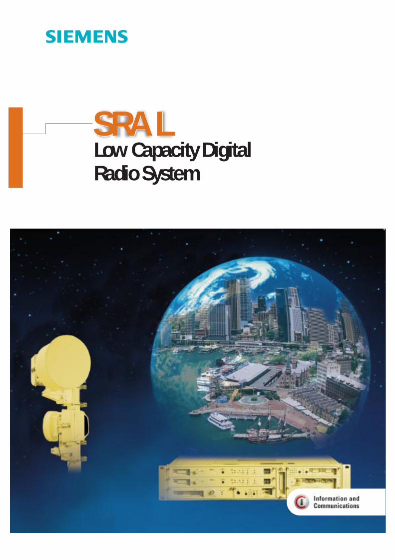
Low Capacity DigitalRadio System
SRA LSRA L
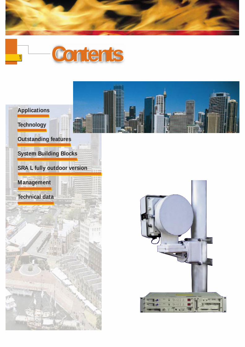
ContentsContents
Applications
Technology
Outstanding features
System Building Blocks
SRA L fully outdoor version
Management
Technical data
1
INTRODUCTION
The market of low capacity radios isgreatly increasing. The GSM/DCS marketis still strongly growing and in the mean-time the GPRS, EDGE and UMTStechnologies are pushing thelow/medium capacity radio systemsintroduction. This is due to thewidespread introduction, in mostcountries, of mobile and personaltelephony and new concepts in theaccess network. In particular GSM,DCSand RLL (Radio in the Local Loop)technologies (DECT, CDMA, etc.), as wellas the access and subscriber distributionnetwork, require very agile and flexibleradio links, for the connection ofequipment and for last-mile connection tomedium and SOHO (Small Office HomeOffice) customers.
Quick provision, high reliability of theservice, very short hop lengths and theurban environment - these are factorswhich have come together to change therequirements that a radio system mustsatisfy in terms of flexibility, performance,management and frequency bands used.
To meet market demand, Siemens hasdeveloped a very flexible and cost-effective family of low capacity digitalradios, the SRA L, with a system conceptapplicable to frequency bands rangingfrom 7 to 55 GHz with a capacity of2/2x2, 4x2, 8x2 and 16x2 Mbit/s. Thislarge frequency coverage is necessary tosatisfy different network configurationsand different propagation conditions.
Being compatible with TCP-IP standards,the communications platform for SRA Lnetworks can be used for the creation ofadvanced solutions as far as supervisionis concerned.
For example, the SRA L network can beconnected via routers to other IP datanetworks (LAN, Intranet or Internet).
The use of TCP-IP communicationsprotocol also allows a whole series ofapplications to be implemented; amongthem audioconferences and file transfers(FTP) between different points of an SRA Lnetwork.
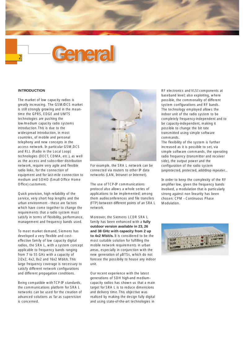
Moreover, the Siemens LCDR SRA Lfamily has been enhanced with a fullyoutdoor version available in 23, 26 and 38 GHz with capacity from 2 up to 4x2 Mbit/s. It is considered to be themost suitable solution for fulfilling themobile network requirements in urbanareas, especially in conjunction with thenew generation of µBTSs, which do notforesee the possibiliy to house any indoorunit.
Our recent experience with the latestgenerations of SDH high-and medium-capacity radios has shown us that a maintarget for SRA L is to reduce dimensionsand delivery time. This objective wasrealised by making the design fully digitaland using state-of-the-art technologies in
GeneralGeneralGeneralRF electronics and VLSI components atbaseband level; also exploiting, wherepossible, the commonality of differentsystem configurations and RF bands.The technology employed allows theindoor unit of the radio system to becompletely frequency-independent and tobe capacity-independent, making itpossible to change the bit ratetransmitted using simple softwarecommands.The flexibility of the system is furtherincreased as it is possible to set, viasimple software commands, the operatingradio frequency (transmitter and receiverside), the output power and theconfiguration of the radio system(unprotected, protected, add/drop repeater...
In order to keep the complexity of the RFamplifier low, given the frequency bandsinvolved, a modulation that is particularlystrong against non linearity has beenchosen: CPM - Continuous PhaseModulation.
2
The main characteristics of the system,which satisfy the new marketrequirements, can be summed up asfollows:
Flexibility, obtained by:
❐ Large frequency coverage (RF bands from 7 up to 38 GHz with the possibility of furtherexpanding the family to the RF bands from 7 up to 55 GHz) using the same indoor unit • Maximum frequency tunability within
the selected RF band• Software controlled operating RF
setting• System capacity controlled through
software and not hardware• Software controlled output power
setting• Flexible system structure
(unprotected/protected,terminal/repeater)
❐ Ease of installation, with small and lightweight indoor and outdoor units connected by a single coaxial cable.Moreover, the outdoor unit is directly connected to the rear of the antenna support by means of a RF interface without any waveguide. It is fixed by means of four retaining latches. The antenna itself is fixed to the pole by means of an appropriate mounting structure. The fully outdoor version is even easier to install.
❐ Very low power consumption thanks tothe use of state-of-the-art technologiesin RF electronics and of VLSI components at baseband level; this also results in better system reliability
❐ No fan needed. This is essential to improving the reliability of the system (a version with a protected fan is available for wide temperature range applications)
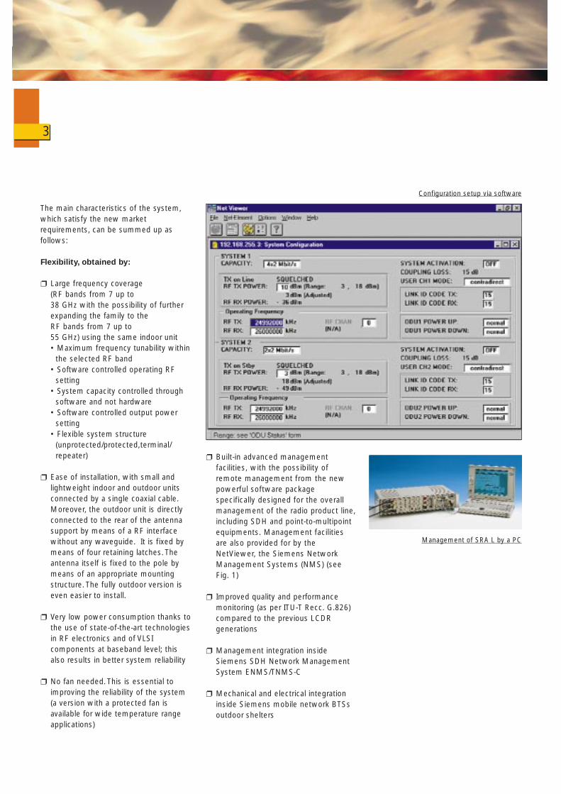
❐ Built-in advanced management facilities, with the possibility of remote management from the new powerful software package specifically designed for the overall management of the radio product line,including SDH and point-to-multipoint equipments. Management facilities are also provided for by the NetViewer, the Siemens Network Management Systems (NMS) (see Fig. 1)
❐ Improved quality and performance monitoring (as per ITU-T Recc. G.826) compared to the previous LCDR generations
❐ Management integration inside Siemens SDH Network Management System ENMS/TNMS-C
❐ Mechanical and electrical integration inside Siemens mobile network BTSs outdoor shelters
3
Management of SRA L by a PC
Configuration setup via software

❐ Mechanical and electrical integrationinside DECTlink (the Siemens RLL equipment based on DECT technology) and CDMAlink (the Siemens RLLequipment based on CDMAtechnology) RBCs (Radio Base StationController) outdoor shelters
❐ Management integration insideSiemens Network ManagementSystem for access network includingRLL network elements AccessIntegrator.
RF channel arrangements
The SRA L digital radio system ispresently intended to operate in the 7, 8,10.5, 13, 15, 18, 23, 26 and 38 GHz frequency bands, with a channelspacing of 3.5, 7, 14 and 28 MHz for2/2x2, 4x2, 8x2 and 16x2 Mbit/s capacityrespectively. Because of the highspectrum efficiency of the CPM formatchosen, it is possible to fulfill the relevantETSI masks even transmitting a high
gross bit rate (nearly 5, 10, 26 and 40Mbit/s for the 2x2, 4x2, 8x2 and 16x2Mbit/s capacity respectively).
In the table below the detailed frequencybands of the SRA L digital radio systemare reported together with the relevantITU-R Recommendations.
Furthermore, the system concept and itsrelevant technologies cover the full rangeof RF bands from 7 up to 55 GHz withvery few hardware changes of RFmodules.
4
Frequency bands (GHz) ITU-R
7.1-7.4 3857.4-7.7 3857.4-7.9 3858.2-8.5 38610.5-10.7 74712.75-13.25 49714.4-15.35 63617.7-19.7 59521.2-23.6 63724.5-26.5 74837.0-39.5 749
SRA L Network
RS 485
NetViewer
SDH Radio Network
Ethernet
Qx
SDH Radio Network
SDH Server
Qx
Customer TCP/IPNetwork
PMP Network
UDP / IPMCF
GNE
Master
GNEGNE
MCF
GNE
Dual Q-A
Figure 1 NetViewer radio network manager
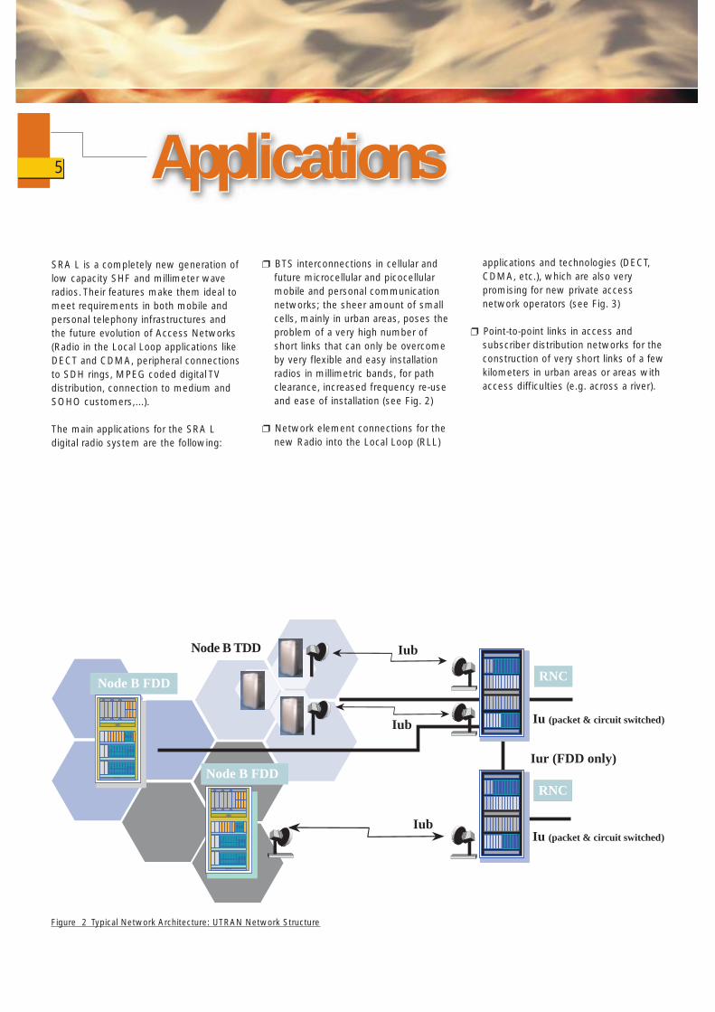
SRA L is a completely new generation oflow capacity SHF and millimeter waveradios. Their features make them ideal tomeet requirements in both mobile andpersonal telephony infrastructures andthe future evolution of Access Networks(Radio in the Local Loop applications likeDECT and CDMA, peripheral connections to SDH rings, MPEG coded digital TVdistribution, connection to medium andSOHO customers,...).
The main applications for the SRA Ldigital radio system are the following:
❐ BTS interconnections in cellular andfuture microcellular and picocellularmobile and personal communication networks; the sheer amount of smallcells, mainly in urban areas, poses the problem of a very high number ofshort links that can only be overcomeby very flexible and easy installationradios in millimetric bands, for pathclearance, increased frequency re-useand ease of installation (see Fig. 2)
❐ Network element connections for the new Radio into the Local Loop (RLL)
ApplicationsApplicationsapplications and technologies (DECT,CDMA, etc.), which are also very promising for new private accessnetwork operators (see Fig. 3)
❐ Point-to-point links in access and subscriber distribution networks for the construction of very short links of a few kilometers in urban areas or areas with access difficulties (e.g. across a river).
5
Node B FDD
BLANK
Node B FDD
BLANK
RNC
RNC
Iub
Iur (FDD only)
Node B TDD
Iu (packet & circuit switched)
Iu (packet & circuit switched)
Iub
Iub
Figure 2 Typical Network Architecture: UTRAN Network Structure

❐ Corporate networks interconnection;SRA L is well suited to theimplementation of inter-PABX links andinter-LAN networks when used inconjunction with bridges and routers.These applications can beimplemented in many differentcontexts over transmission distancesranging from a few hundred metersbetween two buildings to severalkilometers between two sites
❐ Emergency and temporary links to bestarted up in record time. This asset isessential for providing temporaryconnections or for replacing failedtransmission equipment
❐ Fast growing networks, in particularaccess networks like those owned bynew private operators in recentlyderegulated markets, where thequickest and cheapest way to start upand get running is via digital microwaveradio.
6
16 x V5.1 16 x V5.1
8/16 x 2 Mbit/snon redundant
RBS Radio Base Station
RBC Radio Base Station Controller
RDU Radio Distribution Unit
RDU
RBC
RBC
RBC
RBC
RBC
RBC
RBC
RBC
RBS
RBS
RBS
RBS
RBS
RBS
RBS
RBS
RBS
RBS
RBS
RBS
RBS
RBS
RBS
RBS
RBS
RBS
RBS
RBS
RBS
RBS
RBS
RBS
RBS
RBSRBS
RBS
RBS
RBS
RBS
RBS
RDU
Switch
Figure 3 SRA L RLL Networks Application (example)
The system design is based on the useof the most advanced technologies and abig effort has been made to transfercomplexity from analog to digitalhardware in order to take advantage ofcustomised integration (ASICs) and toimprove reliability.
The nature of this technology results inRF electronics: small-sized, lightweight,with low power consumption and highreliability. Furthermore, the high level ofintegration and the reduced number ofinterconnections between modules,together with the choice of a ContinuousPhase Modulation (CPM) scheme,improves mechanical resistance toshocks and vibrations in unavoidableoutdoor installation environments andresults in better stability and immunity tophase hits and microphony.
A full multirate processing in the range4:1 has been the most challenging task inthe implementation of a number offunctions such as multiplexing,add/dropping, signal framing, signalcoding, Forward Error Correction, Tx/Rxsignal shaping, modulation anddemodulation processes. Thus, a fullmultirate capability has been obtained bya fully programmablebaseband/modemodulation hardware andan extensive use of Digital SignalProcessing (DSP).
A particular Continuous PhaseModulation (CPM) format has beenadopted, obtained by properly shapingthe pulses to be modulated to meet theETSI masks for emitted spectral powerdensity even with very high gross bitrates. Given its high immunity to non-linearities, this allows carrier frequencymultiplication and highly efficient nonlinear saturated power amplifiers, thusreducing mechanical dimensions andlowering power consumption.
The choice of a differential demodulation,associated with Viterbi decoding, makesthe SRA L system particularly resistant toshort term frequency instability,frequency jumps and RF oscillator phasenoise, so improving its robustnessagainst mechanical shocks, vibrations andtemperature changes.
The reduced transmitter output back-offand the use of Viterbi decoding givesSRA L the advantage of a system gain ofabout 3 dB with respect to usual shapedQPSK (4-QAM) solutions with coherentdemodulation.
TechnologyTechnologyAt RF level a Modulation Transfer Loop(MTL) is adopted to directly transpose toRF the modulated signal, while the finalstage amplifier is realised with chip-and-wire technology up to 23 GHzand with MMIC technology over 26 GHz.The Tx output power control is operated,on a 24 dB range, through a linear RFattenuator with associated feedbackcontrol.
A dual UHF synthesizer is used forfrequency control and setting, so that thesystem is as independent as possiblefrom the Tx/Rx frequency spacing.
The technology used, and the outdoor unitarchitecture chosen, allow the inclusion ofall the RF-dependent parts of the systemin one single block in the microwavesection, so reducing developing time fornew RF bands and delivery time of theequipment.
7
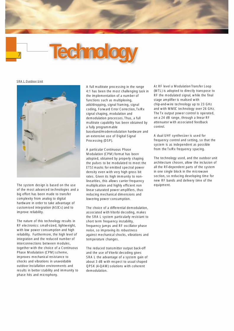
SRA L Outdoor Unit
The key features of the system are:
❐ Performance improvement throughadvanced technology.
❐ Forward Error Correction (FEC).The equipment includes a Reed Solomon error corrector (FEC) with a correction capability of up to 5 errored bytes per frame.This improves the system gain.
❐ RF independent Indoor Unit Any indoor unit can be used with any outdoor unit since they are separately produced and tested in factory.
❐ Large RF bands coverage The SRA L equipment is currently designed to operate in the 7, 8, 10.5,13, 15, 18, 23, 26 and 38 GHz RF bands, but a complete frequency coverage from 7 to 55 GHz can be very easily obtained by changing only few RF modules in the ODU.
❐ Wide frequency coverage of RF unitsand synthesizer (minimum of a wholesub-band).
❐ System configuration-independentmechanical arrangement.All system configurations available make use of the same blocks (hardware) and the configuration change is performed via software.The following configurations are available using the same two 19" rack units high indoor shelf only, with software commands and by using a number of radio transport module cards (the BB-modem cards) and ODU's equivalent to the needed transceivers:• (1+0)• 2x(1+0)• through repeater
• add/drop repeater• (1+1) hot stand-by on 1 or
2 antennas (space diversity option) • (1+1) frequency diversity on 1 or 2
antennas (space diversity).
❐ Software controlled capacity upgrading.The indoor unit of the equipment adopts a baseband structure permitting the software setting, from the linkViewer or NetViewer or from the management system, of the transport capacity while the same outdoor unit is adopted for all the capacities foreseen.
The effective maximum capacity available by using a particular indoorunit is then fixed via software and is managed by means of licence fees.Five types of licences are foreseen:
• 2 Mbit/s fixed capacity• up to 2x2 Mbit/s programmable
capacity• up to 4x2 Mbit/s programmable
capacity• up to 8x2 Mbit/s programmable
capacity• from 8x2 up to 16x2 Mbit/s
programmable capacity.
❐ Maximum software controlled by in-field frequency tunability
The in-field tunability of SRA L is only limited by the RF filters bandwidth limitation necessary to obtain the requested Tx/Rx isolation
❐ Software controlled output powersetting (24 dB range)
This feature is useful to decrease transmitted power when the radio is used for very short hop lengths, so reducing interferences with other links
Outstanding featuresOutstanding features
and improving the nodal efficiency and the flexibility of the system. Moreover,better frequency re-use can be obtained.
❐ Mechanical compactness
The SRA L radio system indoor unit is arranged in two 19" high rack unit shelves, where indoor electronics fortwo (1+0) unprotected systems, also inadd/drop repeater configuration, or one(1+1) hot stand-by or frequency diversity protected system can be housed. Besides, a mechanically compact and light outdoor unit provides ease of handling forequipment set-up and commissioning.Two of these identical ODUs are used for the (1+1) protected or 2x (1+0) configuration.
The antenna diameters for integrated installation with the ODU are 20, 30,60 and/or 120 cm depending on the RFband.
8
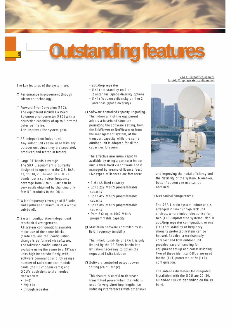
SRA L Outdoor equipment for Add/Drop repeater configuration
❐ Easy and quick installation
Besides the reduced mechanical dimensions and weights of IDU and ODU, the installation of the SRA L radio system is made very easy and quick thanks to the use of a front access only IDU, a single coaxial cable for the connection between IDU and ODU, and a very easy and quick mounting of the outdoor case on the antenna support by means of fourretaining latches avoiding the use of any waveguide.
The protected configuration is obtained using either a dual antenna mechanical structure with each ODU connected to the corresponding antenna in the same way as per the single configuration, or by connecting the two ODUs to a single antenna by means of a RF coupler (hot stand-by) or a circulator (frequency diversity).
❐ Low power consumption
The use of state-of-the-art RF technologies in the microwave part and of VLSI circuits at baseband level has proved remarkably important in reducing power consumption, in increasing the system reliability and in avoiding the use of any fan in the IDU.
❐ No fan use in the IDU (for normaltemperature range)
❐ Built-in advanced managementfacilities.
A suitable network element concept and an optimized embedded software architecture have been selected to allow both a stand alone radio management (LinkViewer and NetViewer software packages) and a radio management fully integrated with Siemens Network Management Systems (NMS).
From these all the software selectable parameters of the SRA L system (like capacity, RF channel, system configuration, output power, etc.) can be set and checked while a complete fault management and performance monitoring, as per G.826 standard, canbe performed locally (LinkViewer) orremotely (NetViewer or NMS).
❐ Software downloading of a completeSRA network from NetViewer or theNetwork Management System
❐ Improved quality and performancemonitoring (as per ITU-T G.826)
❐ Local and remote baseband loopbacks(at 2 Mbit/s level)
❐ Mechanical integration into SiemensBTS outdoor shelters:BS 240/241, able to house six GSM orDCS transceivers in its service rack and BS 40/41, with two transceivers and the new eMICRO BTS.
In this way, the SRA L IDUs can be integrated into the BS 240/241 outdoorshelter and in the BS 40/41 one.Hence the overall system cost can be significantly reduced; when the eMICRO BTS is used no room is thought to be needed for any IDU, so the best solution is to use the fully outdoor version of SRA L.
❐ Mechanical integration into the DectlinkRadio Base Station Controller (RBC)outdoor shelter
This allows Siemens to be in the position to offer a compact, easy to install and affordable solution for Radio in the Local Loop applications. Also in this case the fully outdoor version of SRA L can be used in case of lack of space.
❐ Management integration insideSiemens SDH Network ManagementSystem
❐ Management integration insideSiemens Network ManagementSystem for access network includingRLL network elements AccessIntegrator
9
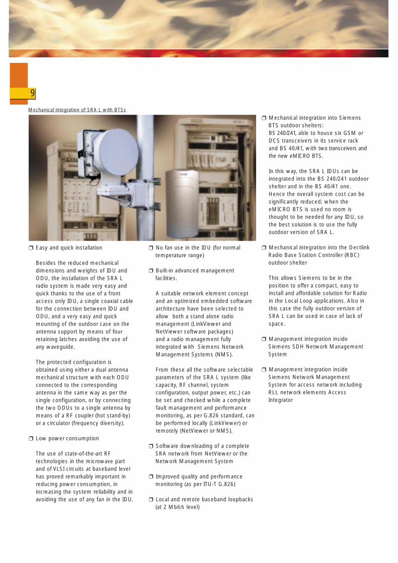
Mechanical integration of SRA L with BTSs

High operating frequency is acharacteristic of the engineering of theSRA L digital radio system. Hence tominimize the feeder loss and installationtime, an indoor/outdoor split configurationhas been chosen. The indoor part,consisting of the baseband and IF units,is connected by means of one (two)single IF coaxial cable to one (two)compact outdoor transceiver integratedwith the antenna (see Fig 4).
Taking into account the networkapplications foreseen for the equipmentand the RF bands adopted, the followingsystem configurations are made available,using the same indoor shelf and thesame indoor blocks (the number of radiotransport modules fit in the shelf is equalto the number of transceivers):
All the configurations mentionedbelow use the same mechanicalstructure as regards the indoorequipment. The change ofconfiguration is performed viasoftware (one radio transport moduleis added to pass from (1+0) to (1+1)or 2x(1+0) or repeater configuration).
Regarding the outdoor unit, a singlecompact mechanical structure isoffered for the single terminalconfiguration and two of theseidentical mechanical structures for theother configurations.In case of unprotected configurations,the ODU is directly connected to therear of the antenna support by astandard RF connector and fixed to itby means of four retaining latches
System Building Blocks
System Building Blocks
without using any waveguide. Themounting of the ODU separate fromthe antenna, useful when an antennabigger than the standard one is usedfor very long hops, can be performedusing a kit for the mounting of theODU to the pole and of a standardwaveguide.
For the protected configurations twosolutions are available; the first usesthe same standard ODU/antennamechanical arrangement of theunprotected configuration, with thetwo ODUs directly connected to therear of two different antennas(normally used with 20 and 30 cmdiameter antennas); the second uses akit composed of a RF coupler and thesupporting hardware for theconnection of the 2 ODUs to a singleantenna (normally used with 60 and120 cm diameter antennas). The firstmounting structure avoids additionalRF losses as regards the unprotectedconfiguration and the same ease ofinstallation, while the second one isadvisable when less disturbance ofthe environment is required.
In Fig. 5 the location of the subunitscomposing the SRA L digital radiosystem is shown together with theavailable external interfaces and thecommunication service channelbetween indoor and outdoor parts(FSK signals) necessary for alarm,status and configuration datatransmission.
10
RX Powermeasurement
IndoorUnit
Rx 70 MHz, FSK 5.5 MHz
coax cable (max length 400m)
Tx 320 MHz, FSK 6.5 MHz, VDC
F(local PC)
Qx/Q3(optional)
64 kbit/sbus structured RS 485
2/2x2/4x2/8x2/16x2Mbit/s
64 kbit/s V.11
EOW (optional)
- radio transport module (up to 2) (BB / Modem unit)- controller- tributary interface- EOW (optional)- Q-Adapter- BB hitless switch
- transmitter- receiver- ODU slave controller- IF diplexer- RF diplexer- dual synthesizer- Tx VCO- Rx VCO- power supply unit
OutdoorUnit
OutdoorUnit
RX Powermeasurement
• single terminal (1+0)• dual terminal 2x(1+0)• through repeater (unprotected)• add/drop repeater (unprotected)• hot stand-by protected terminal (1+1) (on 1 or 2 antennas)• frequency diversity protected terminal (1+1) (on 1 or 2 antennas)
Figure 4 SRA L - System Architecture
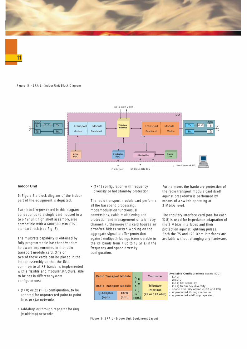
Indoor Unit
In Figure 5 a block diagram of the indoorpart of the equipment is depicted.
Each block represented in this diagramcorresponds to a single card housed in atwo 19" unit high shelf assembly, alsocompatible with a 600x300 mm ETSIstandard rack (see Fig. 6).
The multirate capability is obtained by fully programmable baseband/modem hardware implemented in the radio transport module card. One ortwo of these cards can be placed in the indoor assembly so that the IDU,common to all RF bands, is implemented with a flexible and modular structure, able to be set in different system configurations:
• (1+0) or 2x (1+0) configuration, to beadopted for unprotected point-to-pointlinks or star networks
• Add/drop or through repeater for ring(multidrop) networks
• (1+1) configuration with frequencydiversity or hot stand-by protection.
The radio transport module card performsall the baseband processing,modemodulation functions, IFconversions, cable multiplexing andprotection and management of telemetrychannel. Furthermore this card houses anerror-free hitless switch working on theaggregate signal to offer protectionagainst multipath fadings (considerable inthe RF bands from 7 up to 18 GHz) in thefrequency and space diversityconfiguration.
Furthermore, the hardware protection ofthe radio transport module card itselfagainst breakdown is performed bymeans of a switch operating at 2 Mbit/s level.
The tributary interface card (one for eachIDU) is used for impedance adaptation ofthe 2 Mbit/s interfaces and theirprotection against lightning pulses.Both the 75 and 120 Ohm interfaces areavailable without changing any hardware.
11
Radio T ransport ModuleAvailable Configurations (same IDU)- (1+0)- 2x(1+0)- (1+1) hot stand-by- (1+1) frequency diversity- space diversity option (HSB and FD)- unprotected through repeater- unprotected add/drop repeater
Radio T ransport Module
Q-Adapter(opt.)
EOW(opt.)
Controller
TributaryInterface
(75 or 120 ohm)
Alarm
Unit
(opt.)
Tx
Rx
Transport Module
Modem Baseband
up to 16x2 Mbit/s
Tx
RxModemBaseband
IDU
ODU ODU
Hop/Network PC
Q interface 64 kbit/s RS 485
Transport Module
EOW(opt)
Q_Adapter
(opt)Controller
Alarm
Unit
Tributary
interface
Figure 6 SRA L - Indoor Unit Equipment Layout
Figure 5 - SRA L - Indoor Unit Block Diagram
The controller card is in charge of internalsupervision and protocol handlingtowards local and remote managementinterfaces, whilst the alarm card isoptionally used to as a parallel alarminterface.
The equipment can also include thefollowing two units as options:
• The Q-Adapter card, to be installed inthe gateway network elementrestituting a Qx/Q3 (or a QD2) interfacetowards the Siemens networkmanagement system.
• The EOW card that allows building up aservice channel network adoptingDTMF signalling (selective calling).
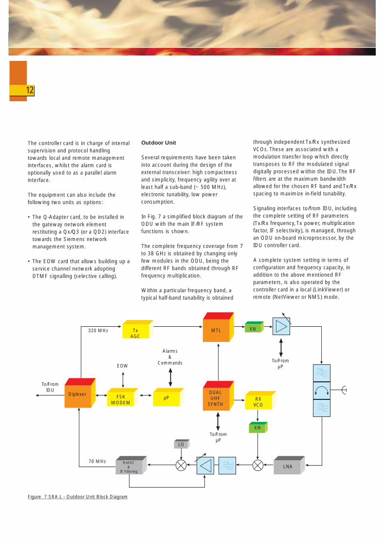
Outdoor Unit
Several requirements have been takeninto account during the design of theexternal transceiver: high compactnessand simplicity, frequency agility over atleast half a sub-band (~ 500 MHz),electronic tunability, low powerconsumption.
In Fig. 7 a simplified block diagram of theODU with the main IF/RF systemfunctions is shown.
The complete frequency coverage from 7to 38 GHz is obtained by changing onlyfew modules in the ODU, being thedifferent RF bands obtained through RFfrequency multiplication.
Within a particular frequency band, atypical half-band tunability is obtained
through independent Tx/Rx synthesizedVCOs. These are associated with amodulation transfer loop which directlytransposes to RF the modulated signaldigitally processed within the IDU. The RFfilters are at the maximum bandwidthallowed for the chosen RF band and Tx/Rxspacing to maximize in-field tunability.
Signaling interfaces to/from IDU, includingthe complete setting of RF parameters(Tx/Rx frequency, Tx power, multiplicationfactor, IF selectivity), is managed, throughan ODU on-board microprocessor, by theIDU controller card.
A complete system setting in terms ofconfiguration and frequency capacity, inaddition to the above mentioned RFparameters, is also operated by thecontroller card in a local (LinkViewer) orremote (NetViewer or NMS) mode.
12
Figure 7 SRA L - Outdoor Unit Block Diagram
MTL
DUALUHF
SYNTH
FSKMODEM
RXVCO
XN
LO
LNARxAGC
&IF Filtering
Diplexer
XNTxAGC
µP
To/FromµP
To/FromµP
To/FromIDU
320 MHz
70 MHz
EOW
Alarms&
Commands
13
The link between the SRA L fully outdoor versio
SRAL
SPLIT VERSION SRA L
SRA L IDU inside a BTS
FULLY OUTDOOR SRA L
ion (right) and SRA L split version (left)
Fully ODU
eMICRO BTS

General
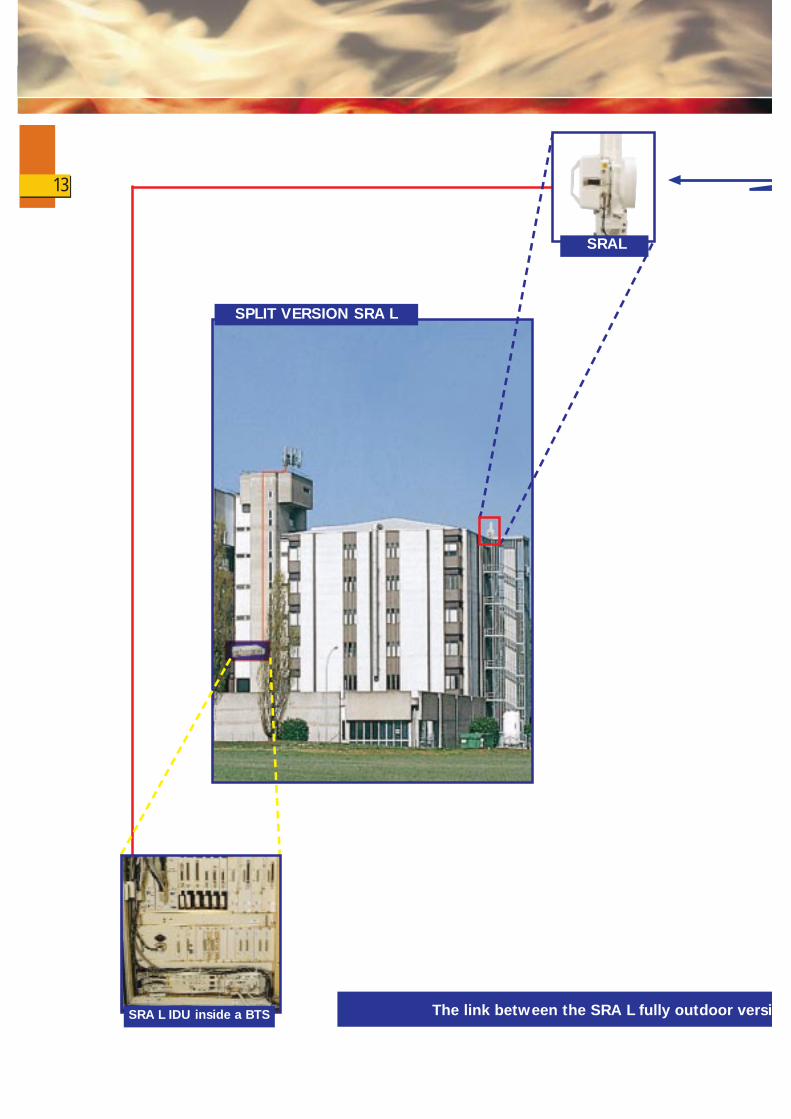
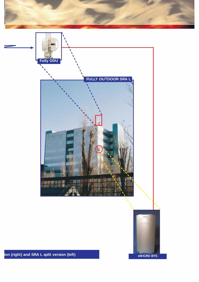
The SRA L radio family has beenenhanced a fully outdoor version(complete outdoor practice) available in23, 26, 38 GHz bands with capacity of2/2x2, 4x2 Mbit/s. This is the mostsuitable solution for mobile networkrequirements in urban environments,when the new generation of µBTSs(which will not be able to house IndoorUnits) are used for hot spot coverage.
Although all the baseband and IFfunctionality have been integrated in theOutdoor Unit, the same version has beenmaintained, preserving the followingelements in common:
• Mechanical dimension
• Installation procedure
• Microwave parts
• Integrated antennas.
The same RF air interface as the splitversion (IDU/ODU) has been maintainedmaking it possible to set up even anasymmetrical link (SRA L split - SRA Lfully outdoor), as in the figures on pages13 and 14.
The mechanical arrangement of SRA LFully Outdoor consist of a case integratedon the rear of the antenna and an uniquemultipair cable able to carry all thesignals. The multipair cable is connecteddirectly into the new eMICRO BTSthrough one of its interface modules.
The Fully Outdoor version is completelyintegrated within the Siemens networkmanagement "umbrella" as well as theSRA L split version.
The SRA L fullyoutdoor versionThe SRA L fullyoutdoor version
System building block
❐ Taking into account the expectednetwork applications for this equipmentthe Base Band and IF functionalities aremechanically embedded, with the RFpart in the same ODU case of the splitSRA L
❐ A single multipair cable for eachtransceiver is used. The signals carriedon the cable are the following (Fig.8):
15

• 2x2 or 4x2 Mbit/s signals
• NMS channel
• PC connection channel
• 2 alarms
• DC power supply
❐ An optional connection box is availablewith the functions listed below:
• AC/DC converter (can be inserted as an option)
• Power feed hold - over function (can be inserted as an option)
• Back-up batteries (can be inserted as an option)
• 2 Mbit/s interfaces 120 ohm G.703 interface at ODU connector
• Parallel alarm interface
• DC power supply input
• AC power supply input
• Multipair cable interface
• PC converter
• RS 485 Bus interface forNMS channel interconnection.
16
Figure 8 - SRA L Fully Outdoor Building Block
Signal carried on the cable:Nms channelPC connection channel2 Mbit/s tributariestwo alarms (IND & URG)DC power Supply
ODU
CONNECTION BOX
ODU:transmitterreceivercontrollerBB & IF partsRF diplexerdual synthesizerTx VCORx VCOpower supplyunit
Connection Box:AC/DC converterPower Feed Hold-Over functionalityBack-up Batteries2 Mbit/s Trib. InterfacesParallel Alarm InterfaceDC Power Supply InputAC Power Supply InputMultipair Cble InterfacePC connectionNMS channel daisy chain interconnection
multipair cable
2/2x2/4x2 Mbit/s
d=200 mt
(Optional)Connection box
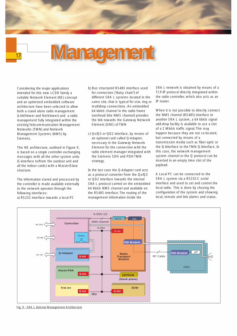
Considering the major applicationsintended for this new LCDR family asuitable Network Element (NE) conceptand an optimized embedded softwarearchitecture have been selected to allowboth a stand alone radio management(LinkViewer and NetViewer) and a radiomanagement fully integrated within theexisting Telecommunication ManagementNetworks (TMN) and NetworkManagement Systems (NMS) bySiemens.
This NE architecture, outlined in Figure 9,is based on a single controller exchangingmessages with all the other system units (S-interface to/from the outdoor unit andall the indoor cards) with a Master/Slavestructure.
The information stored and processed bythe controller is made available externallyto the network operator through thefollowing interfaces:a) RS232 interface towards a local PC
b) Bus structured RS485 interface usedfor connection ("daisy chain") ofdifferent SRA L systems located in thesame site, that is typical for star, ring ormultidrop connections. An embedded64 kbit/s channel in the radio frameoverhead (the NMS channel) providesthe link towards the Gateway NetworkElement (GNE) of TMN
c) Qx/Q3 or QD2 interface, by means ofan optional card called Q-Adapter,necessary in the Gateway NetworkElement for the connection with theradio element manager integrated withthe Siemens SDH and PDH TMNstrategy.
In the last case the Q-Adapter card actsas a protocol converter from the Qx/Q3or QD2 interface towards the internalSRA L protocol carried on the embedded64 kbit/s NMS channel and available onthe RS485 interface. The routing of themanagement information inside the
ManagementManagementSRA L network is obtained by means of aTCP-IP protocol directly integrated withinthe radio controller, which also acts as anIP router.
When it is not possible to directly connectthe NMS channel (RS485) interface toanother SRA L system, a 64 kbit/s signaladd-drop facility is available to use a slotof a 2 Mbit/s traffic signal. This mayhappen because they are not co-located,but connected by means of atransmission media such as fiber optic orthe Q-Interface to the TMN Q-Interface. Inthis case, the network managementsystem channel or the Q protocol can beinserted in an empty time slot of thepayload.
A Local PC can be connected to the SRA L system via a RS232-C serialinterface and used to set and control thelocal radio. This is done by chosing theconfiguration of the system and showinglocal, remote and link alarms and status.
17
Controller
Routing
Q-AdapterS-Int
Alarm/FAN
S-Int
Trib-Int
S-IntIDU
EOW
S-Int
EEPROM
(black-plane)
S-Int
S-ODU 1/2
NMS channel
S-IDU
RadioTransport
Module
RS 232C
RS 485
Qx / Q3RF Cable
µP
ODU
ODU-Int
FSK Modem
FSK Modem
ASIC
Fig. 9 - SRA L Internal Management Architecture
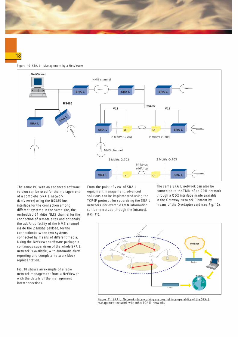
The same PC with an enhanced softwareversion can be used for the managementof a complete SRA L network(NetViewer) using the RS485 businterface for the connection amongdifferent systems in the same site, theembedded 64 kbit/s NMS channel for theconnection of remote sites and optionallythe add/drop facility of the NMS channelinside the 2 Mbit/s payload, for theconnectionbetween two systemsconnected by means of different media.Using the NetViewer software package a continuous supervision of the whole SRA Lnetwork is available, with automatic alarm reporting and complete network block representation.
Fig. 10 shows an example of a radio network management from a NetViewerwith the details of the management interconnections.
From the point of view of SRA Lequipment management, advancedsolutions can be implemented using theTCP-IP protocol, for supervising the SRA Lnetworks (for example TMN informationcan be remotized through the Intranet).(Fig. 11).
The same SRA L network can also beconnected to the TMN of an SDH networkthrough a QD2 interface made available in the Gateway Network Element bymeans of the Q-Adapter card (see Fig. 12).
18
LT LT
RS485
NMS channel
RS485
NMS channel
2 Mbit/s G.703 2 Mbit/s G.703
64 kbit/sadd/drop
LT LT
V11 V11
2 Mbit/s G.703 2 Mbit/s G.703
NetViewer
SRA L
SRA L
SRA L SRA L
SRA LSRA L
SRA L SRA L
SRA L
Router
INTERNET
Intranet
Router
Figure 10 SRA L - Management by a NetViewer
Figure 11 SRA L Network - Interworking assures full interoperability of the SRA Lmanagement network with otherTCP-IP networks

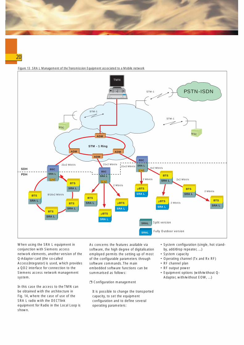
The SRA L element manager can beintegrated inside the Siemens SDHElement Manager Operating System usedfor the network element management ofthe Siemens SDH network elements. Thisintegration gives the big advantage, thanksto the use of the Q-Adapter facility, ofhaving an integrated solution for themanagement of a whole SDH network andthe PDH links from it obtained by using theSRA L equipment (see Fig. 12).Thisadvantage is further highlighted by the factthat the Siemens SDH operating systemcan also perform the network control layerfacilities.These two possibilities of remote networkmanagement of a SRA L network becomeeven more interesting in the case ofmobile networks. In fact, in this case, theSRA L equipment is used in the last layerof the network (for BTSs interconnection)while for the connection of BSCs to MSCs
and among MSCs or from MSCs toPSTN/ISDN higher capacities are used thenmaking SDH network a must (see Fig. 13).
When starting up a mobile network, theradio infrastructure is used only for theBTSs interconnection (SRA L), and usesleased lines for the other network layers.At this stage, the NetViewer is the best,quickest and cheapest way to start theservice. The Siemens TMN operatingsystem is introduced only when theincreasing number of the customersprompts the operator to build up theother part of the transmission network. Inthis way the big advantages of SDH interms of protection (ring architectures),performance monitoring, trafficprovisioning and TMN can be introducedsaving the previous investments andresulting in a cheaper and betterperforming network.
19
Figure 12 SRA L Management of SRA L equipment in conjunctions with SDH
ENMS/TNMS-C
DCNSMA
SMA
SMASMA
A Line
A Line
A Line
Router
Backbone Network
SDH Network STM 1/4/16
POTS/ISDN
DACS
ATMSW
A Line
PBX
SRA L
CPECPE CPE
SRA L
ATM5W
SRA LSRA L
SRA L SRA LSRA L
SMA
SMA
SMASMA
SMA SMA 1K
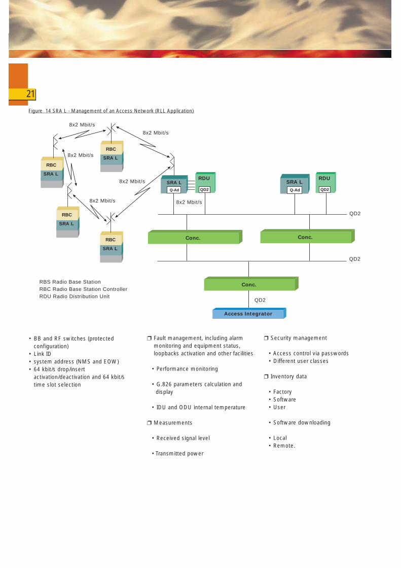
When using the SRA L equipment inconjunction with Siemens accessnetwork elements, another version of theQ-Adapter card (the so-calledAccessIntegrator) is used, which providesa QD2 interface for connection to theSiemens access network managementsystem.
In this case the access to the TMN canbe obtained with the architecture in Fig. 14, where the case of use of theSRA L radio with the DECTlinkequipment for Radio in the Local Loop isshown.
As concerns the features available viasoftware, the high degree of digitalisationemployed permits the setting up of mostof the configurable parameters throughsoftware commands. The mainembedded software functions can besummarised as follows:
❐ Configuration management
It is possible to change the transportedcapacity, to set the equipmentconfiguration and to define severaloperating parameters:
• System configuration (single, hot stand-by, add/drop repeater, ...)
• System capacity• Operating channel (Tx and Rx RF)• RF channel plan• RF output power• Equipment options (with/without Q-
Adapter, with/without EOW, ...)
20
8/16x2 Mbit/s
PSTN-ISDN
STM-1
21x2 Mbit/s 21x2 Mbit/s
2 Mbit/s
STM - 1 Ring
21x2 Mbit/s
2 Mbit/s
4x2 Mbit/s
2x2 Mbit/s
2 Mbit/s
MSC
STM-1
ADM
ADM
SRA L
µBTS
SRA L
µBTS
SRA L
BSC
Q-Ad
SRA L
µBTS
SRA L
µBTS2 Mbit/s
SRA L
BSC
Q-AdSDH
PDH SRA L
BSC
ADM
SRAL
Split version
Fully Outdoor version
MSC
SRA L
BTS
SRA L
BTSSRA L
BTS
SRA L
BTS
SRA L
BTS
SRA L
BTS
SRA L
BTS
SRA L
BTS
SRAL
Q-Ad
STM-1
ADM
TMN
Figure 13 SRA L Management of the Transmission Equipment associated to a Mobile network
• BB and RF switches (protectedconfiguration)
• Link ID• system address (NMS and EOW)• 64 kbit/s drop/insert
activation/deactivation and 64 kbit/stime slot selection
❐ Fault management, including alarmmonitoring and equipment status,loopbacks activation and other facilities
• Performance monitoring
• G.826 parameters calculation and display
• IDU and ODU internal temperature
❐ Measurements
• Received signal level
• Transmitted power
❐ Security management
• Access control via passwords• Different user classes
❐ Inventory data
• Factory• Software• User
• Software downloading
• Local• Remote.
21
QD2
QD2
8x2 Mbit/s
8x2 Mbit/s
8x2 Mbit/s
8x2 Mbit/s
8x2 Mbit/s
8x2 Mbit/s
QD2
RBS Radio Base StationRBC Radio Base Station ControllerRDU Radio Distribution Unit
SRA L
Q-Ad
SRA L
Q-Ad
SRA L
RBC
SRA L
RBC
SRA L
RBC
RDU
QD2
RDU
QD2
Access Integrator
Conc.
Conc. Conc.
SRA L
RBC
Figure 14 SRA L - Management of an Access Network (RLL Application)
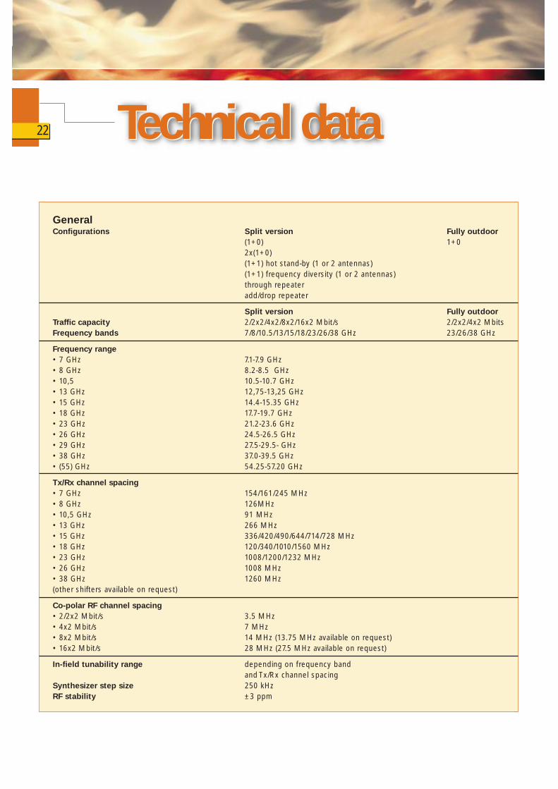
GeneralConfigurations Split version Fully outdoor
(1+0) 1+02x(1+0)(1+1) hot stand-by (1 or 2 antennas)(1+1) frequency diversity (1 or 2 antennas)through repeateradd/drop repeater
Split version Fully outdoorTraffic capacity 2/2x2/4x2/8x2/16x2 Mbit/s 2/2x2/4x2 MbitsFrequency bands 7/8/10.5/13/15/18/23/26/38 GHz 23/26/38 GHz
Frequency range• 7 GHz 7.1-7.9 GHz• 8 GHz 8.2-8.5 GHz• 10,5 10.5-10.7 GHz• 13 GHz 12,75-13,25 GHz• 15 GHz 14.4-15.35 GHz• 18 GHz 17.7-19.7 GHz• 23 GHz 21.2-23.6 GHz• 26 GHz 24.5-26.5 GHz• 29 GHz 27.5-29.5- GHz• 38 GHz 37.0-39.5 GHz• (55) GHz 54.25-57.20 GHz
Tx/Rx channel spacing• 7 GHz 154/161/245 MHz• 8 GHz 126MHz• 10,5 GHz 91 MHz• 13 GHz 266 MHz• 15 GHz 336/420/490/644/714/728 MHz• 18 GHz 120/340/1010/1560 MHz• 23 GHz 1008/1200/1232 MHz• 26 GHz 1008 MHz• 38 GHz 1260 MHz(other shifters available on request)
Co-polar RF channel spacing• 2/2x2 Mbit/s 3.5 MHz• 4x2 Mbit/s 7 MHz• 8x2 Mbit/s 14 MHz (13.75 MHz available on request)• 16x2 Mbit/s 28 MHz (27.5 MHz available on request)
In-field tunability range depending on frequency bandand Tx/Rx channel spacing
Synthesizer step size 250 kHzRF stability ±3 ppm
Technical dataTechnical data22
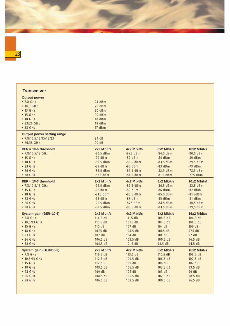
TransceiverOutput power• 7/8 GHz 24 dBm• 10,5 GHz 20 dBm• 13 GHz 20 dBm• 15 GHz 20 dBm• 18 GHz 18 dBm• 23/26 GHz 18 dBm• 38 GHz 17 dBm
Output power setting range• 7/8/10.5/13/15/18/23 24 dB• 26/38 GHz 20 dB
BER = 10-6 threshold 2x2 Mbit/s 4x2 Mbit/s 8x2 Mbit/s 16x2 Mbit/s• 7/8/10,5/13 GHz -90.5 dBm -87.5 dBm -84.5 dBm -80.5 dBm• 15 GHz -90 dBm -87 dBm -84 dBm -80 dBm• 18 GHz -89.5 dBm -86.5 dBm -83.5 dBm -79.5 dBm• 23 GHz -89 dBm -86 dBm -83 dBm -79 dBm• 26 GHz -88.5 dBm -85.5 dBm -82.5 dBm -78.5 dBm• 38 GHz -87.5 dBm -84.5 dBm -81.5 dBm -77.5 dBm
BER = 10-3 threshold 2x2 Mbit/s 4x2 Mbit/s 8x2 Mbit/s 16x2 Mbits/• 7/8/10,5/13 GHz -92.5 dBm -89.5 dBm -86.5 dBm -82,5 dBm• 15 GHz -92 dBm -89 dBm -86 dBm -82 dBm• 18 GHz -91.5 dBm -88.5 dBm -85.5 dBm -81,5dBm• 23 GHz -91 dBm -88 dBm -85 dBm -81 dBm• 26 GHz -90.5 dBm -87.5 dBm -84.5 dBm -80,5 dBm• 38 GHz -89.5 dBm -86.5 dBm -83.5 dBm -79,5 dBm
System gain (BER=10-6) 2x2 Mbit/s 4x2 Mbit/s 8x2 Mbit/s 16x2 Mbit/s• 7/8 GHz 114.5 dB 111.5 dB 108.5 dB 104.5 dB• 10,5/13 GHz 110.5 dB 107.5 dB 104.5 dB 100.5 dB• 15 GHz 110 dB 107 dB 104 dB 100 dB• 18 GHz 107.5 dB 104.5 dB 101.5 dB 97.5 dB• 23 GHz 107 dB 104 dB 101 dB 97 dB• 26 GHz 106.5 dB 103,5 dB 100.5 dB 96.5 dB• 38 GHz 104.5 dB 101.5 dB 98.5 dB 94.5 dB
System gain (BER=10-3) 2x2 Mbit/s 4x2 Mbit/s 8x2 Mbit/s 16x2 Mbit/s• 7/8 GHz 116.5 dB 113.5 dB 110.5 dB 106.5 dB• 10,5/13 GHz 112.5 dB 109.5 dB 106.5 dB 102.5 dB• 15 GHz 112 dB 109 dB 106 dB 102 dB• 18 GHz 109.5 dB 106.5 dB 103.5 dB 99.5 dB• 23 GHz 109 dB 106 dB 103 dB 99 dB• 26 GHz 108.5 dB 105.5 dB 102.5 dB 98.5 dB• 38 GHz 106.5 dB 103.5 dB 100.5 dB 96.5 dB
23
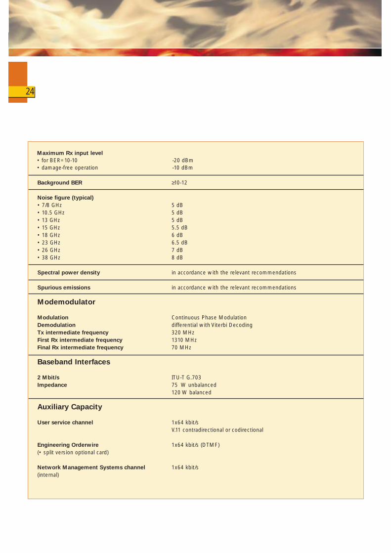
Maximum Rx input level• for BER=10-10 -20 dBm• damage-free operation -10 dBm
Background BER ≥10-12
Noise figure (typical)• 7/8 GHz 5 dB• 10.5 GHz 5 dB• 13 GHz 5 dB• 15 GHz 5.5 dB• 18 GHz 6 dB• 23 GHz 6.5 dB• 26 GHz 7 dB• 38 GHz 8 dB
Spectral power density in accordance with the relevant recommendations
Spurious emissions in accordance with the relevant recommendations
Modemodulator
Modulation Continuous Phase ModulationDemodulation differential with Viterbi DecodingTx intermediate frequency 320 MHzFirst Rx intermediate frequency 1310 MHzFinal Rx intermediate frequency 70 MHz
Baseband Interfaces
2 Mbit/s ITU-T G.703Impedance 75 W unbalanced
120 W balanced
Auxiliary Capacity
User service channel 1x64 kbit/sV.11 contradirectional or codirectional
Engineering Orderwire 1x64 kbit/s (DTMF)(• split version optional card)
Network Management Systems channel 1x64 kbit/s(internal)
24

Power Supply
Nominal voltage -24/-60 VDCTolerance ± 20%
Power Consumption (from battery)
1+0 (IDU+ODU split version) 40 W1+0 (Fully outdoor) < 40 W
Environmental Operating Conditions
The equipment meets the environmental conditions standardized in ETSI prETS 300 019.Split versionIndoor unit• normal temperature range 10 to +50°C• extended temperature range -10 to +60°C
Outdoor unit• normal temperature range -33 to +60°C• extended temperature range -50 to +60°C
Fully Outdoor version -33 to +55° C
Mechanical Dimensions
Indoor Unit 2 U (19")Outdoor Unit 260x260x120 mm (hxwxd)
Software Features
System type setting (1+0)/2x(1+0)add/drop through repeater(1+1) hot stand-by(1+1) frequency diversity
System parameter setting operating channel (Tx and Rx)RF channel planRF output powercapacity 2,2x2, 4x2, 8x2, 16x2 Mbit/s)system address (EOW and NMS)link ID
25
26
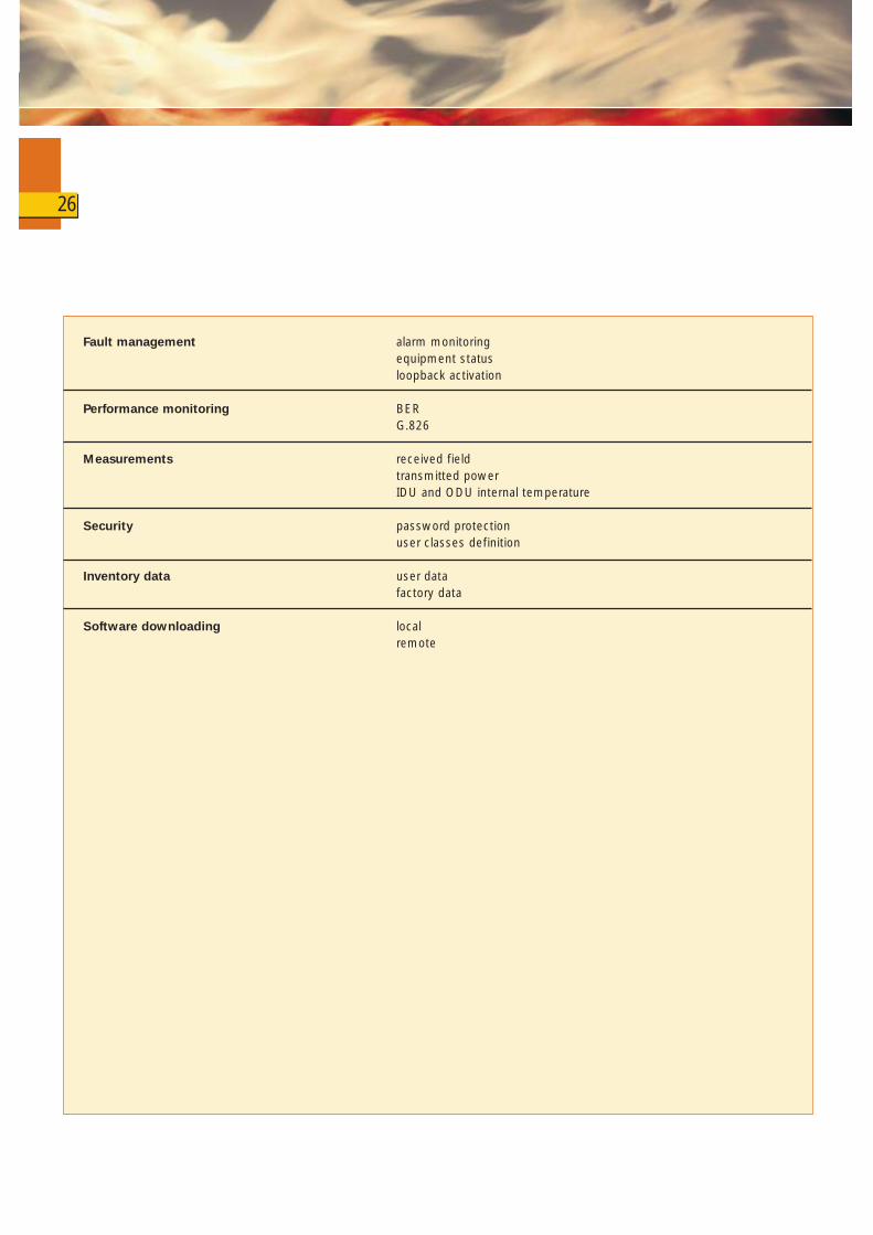
Fault management alarm monitoringequipment statusloopback activation
Performance monitoring BERG.826
Measurements received fieldtransmitted powerIDU and ODU internal temperature
Security password protectionuser classes definition
Inventory data user datafactory data
Software downloading localremote
Related Documents