6.0 SYSTEM DESIGN System Design Process – transforms the analysis model into design model Process: 1) Decomposition (guided by design goals) 2) Hardware/software platform mapping (deployment diagram) 3) Persistent data (DB) 4) Overall control flow (activity/collaboration diagram) 5) Access control policy 6) Boundary conditions Transitional activities from system spec (RAD) to final system construction A) system design B) object design C) implementation

6.0 SYSTEM DESIGN System Design Process – transforms the analysis model into design model Process: 1) Decomposition (guided by design goals) 2) Hardware/software.
Dec 18, 2015
Welcome message from author
This document is posted to help you gain knowledge. Please leave a comment to let me know what you think about it! Share it to your friends and learn new things together.
Transcript
6.0 SYSTEM DESIGN
System Design Process – transforms the analysis model into design model
Process: 1) Decomposition (guided by design goals) 2) Hardware/software platform mapping (deployment diagram) 3) Persistent data (DB) 4) Overall control flow (activity/collaboration diagram) 5) Access control policy 6) Boundary conditions
Transitional activities from system spec (RAD) to final system construction
A) system design B) object design C) implementation
6.0 SYSTEM DESIGN
6.1 Introduction
Step A – System design
Elicitation of specs focuses on functionality and goals System design focuses on data structures, processes, software, hardware,
legacy systems The decomposition process entails matching design goals against constraints (See Fig 6.1 – successive changes indicates matching constraints against
user goals)
Similarities (House design vs. Software Engineering): i) Rooms – subsystems v) Kitchen layout – coding
complexity/modularity ii) Doors – interfaces/services vi) Re-draw/moving walls – redesign of
interfaces iii)Living area – response time/QoS iv) No. of rooms – use cases

N
Bedroom2MasterBedroom
Dining
Hallway
Stairs
Bath
Kitchen
Study
Bath
Kitchen
MasterBedroom
Dining
Hallway
Stairs
Entrance
door
MasterBedroom
Bedroom2
Dining
Hallway
Stairs
Entrancedoor
Study
Study
Bath
Kitchen
Bedroom2
Entrancedoor
Version 1Version 2
Version 3
Figure 6-1. Example of iterative floor plan design. Three successive versions show how we minimize walking distance and take advantage of sunlight.

6.0 SYSTEM DESIGN
6.2 Overview
System design – addresses the internal structure or software architecture of the system, and how the internal functions are impacted by the external/operating environment, e.g., OS, DB, hardware platform
Results of system design –
optimized design goals (derived from the non-functional requirements) the software architecture (guided by several issues)

6.0 SYSTEM DESIGN
6.2 Overview – 1
Issues that guide system decomposition – toward the software architecture i) hardware/software mapping – processors, communication, data migration,
concurrency, services using off-the-shelf, DB, user-interfaces, compo encapsulation
ii) data management – persistency, storage, control, access, security, consistency, retrieval, reliability/availability, overall DBMS
iii) Access Control – policy and mechanism, extent (system-wide or select components)
iv) Control Flow – sequence of operations (in embedded system world = software architecture), event-driven, interrupt-driven, OS-control – threads with semaphores/CS
V) Boundary conditions – initialization, exception handling (nesting?), e.g., in distributed systems, shutdown
(See Fig 6.2)

Describe boundaryconditions
Define Definesubsystems
Map subsystemsto hardware/
Manage
Select a
Define access
design goals
persistent data
control policies
global
Implementsubsystems
software platform
control flow
Figure 6-2. The activities of system design (UML activity diagram).

6.0 SYSTEM DESIGN
6.3 SD Concepts – System Decomposition
Properties: Subsystem – a) Application domain is decomposed into Classes and
organized as Packages and b) Solution domain is decomposed into Parts (domain Classes and Subsystems
Interfaces – subsystems provide services through the interfaces. Services are related operations which a subsystem implements to support others. (System design focuses on the ‘services’ definition and Object design focuses on the ‘operational details’ for implementing/realizing the services.)
Coupling/Coherence – aspects of subsystem dependencies (low coupling and high cohesion)
Layering – organizing a system as hierarchy of subsystems (lower layers support upper layers)
Partitioning – organizing subsystems into peer-to-peer service providers
All 6 properties define the software architecture
E.g. (Fig 6-3 – decomposition, and Fig 6-4 – decomposition into packages)

Classparts
*System Part*
Subsystem
Figure 6-3. Subsystem decomposition (UML class diagram).

NotificationIncidentManagement
FieldOfficerInterface DispatcherInterface
Figure 6-4. Subsystem decomposition for an accident management system (UML class diagram, collapsed view). Subsystems are shown as UML packages. Dashed arrows indicate dependencies between subsystems.
6.0 SYSTEM DESIGN
6.3.2 SD Concepts – Services and Interfaces
Service – a set of complementary operations serving the needs of client subsystems, e.g., ‘notification service [ops to snd/recv notices, channel alloc, ..]
Interfaces – the collection of services subsystems provide in an environment (also called API) includes the op types, parameters, name of ops, constraints – access control, return values, etc.
SD – focused on defining and designing the high-level behaviors in the interfaces (without implementation details) – and abstraction concept
6.0 SYSTEM DESIGN
6.3.3 SD Concepts – Coupling and Coherence
Coupling – measure of the degree of subsystem dependencies; highly coupled subsystems are highly dependent and changes in one has more impact on others
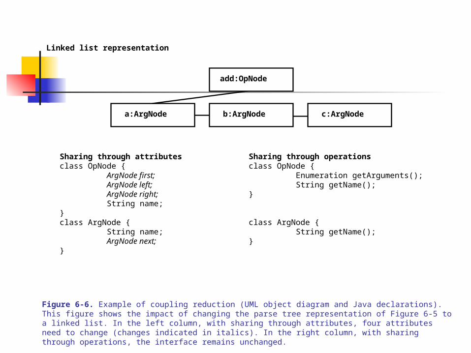
(See Fig 6-5 and Fig 6-6 – a syntax and semantic analyzer subsystem sharing a parse-tree – common interface – via attributes vs. via operations. Interfacing via operations requires no changes to interface, hence the two subsystems won’t change)
Coherence – measure of the strength of object (inter)dependencies within a subsystem in performing complementary tasks. (Low coherence is not good!)
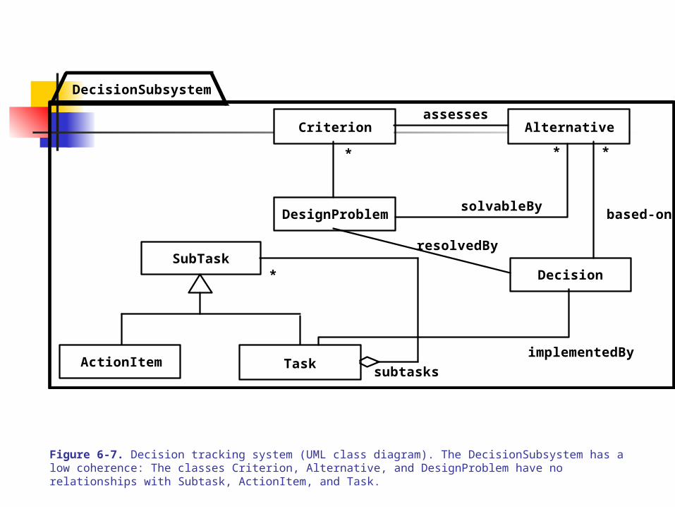
(See Fig 6-7 – with low coherence and Fig 6-8 – with reduced complexity and increased coherence in 2 subsystems using the 7 +/- 2 decomposition rule)

add1:OpNode
add2:OpNode
c:ArgNodeb:ArgNode
a:ArgNode
Binary tree representation
Sharing through attributesclass OpNode {
ArgNode left;ArgNode right;String name;
}class ArgNode {
String name;}
Sharing through operationsclass OpNode {
Enumeration getArguments();String getName();
}
class ArgNode {String getName();
}
Figure 6-5. Example of coupling reduction (UML object diagram and Java declarations). This figure shows a parse tree for the expression “a + b + c”. The left column shows the interface of the OpNode class with sharing through attributes. The right column shows the interface of OpNode with sharing through operations. Figure 6-6 shows the changes for each case when a linked list is selected instead.
add:OpNode
c:ArgNodeb:ArgNodea:ArgNode
Linked list representation
Sharing through attributesclass OpNode {
ArgNode first;ArgNode left;ArgNode right;String name;
}class ArgNode {
String name;ArgNode next;
}
Sharing through operationsclass OpNode {
Enumeration getArguments();String getName();
}
class ArgNode {String getName();
}
Figure 6-6. Example of coupling reduction (UML object diagram and Java declarations). This figure shows the impact of changing the parse tree representation of Figure 6-5 to a linked list. In the left column, with sharing through attributes, four attributes need to change (changes indicated in italics). In the right column, with sharing through operations, the interface remains unchanged.
Alternative
Decision
Criterion
subtasks
*SubTask
ActionItem
DesignProblem
Task
assesses
solvableBy
resolvedBy
based-on
* * *
implementedBy
DecisionSubsystem
Figure 6-7. Decision tracking system (UML class diagram). The DecisionSubsystem has a low coherence: The classes Criterion, Alternative, and DesignProblem have no relationships with Subtask, ActionItem, and Task.

subtasks
*
assesses
solvableBy
resolvedBy
based-on
* * *
implementedBy
RationaleSubsystem
PlanningSubsystem
Criterion Alternative
Decision
DesignProblem
SubTask
ActionItem Task
Figure 6-8. Alternative subsystem decomposition for the decision tracking system of Figure 6-7 (UML class diagram). The coherence of the RationaleSubsystem and the PlanningSubsystem is higher than the coherence of the original DecisionSubsystem. Note also that we also reduced the complexity by decomposing the system into smaller subsystems.

6.0 SYSTEM DESIGN
6.3.4 Layer and Partitions
One design goal – to reduce complexity by problem decomposition Layers:
Layered architecture – in which lower layers support upper ones (with abstraction)
(See Fig 6.9)
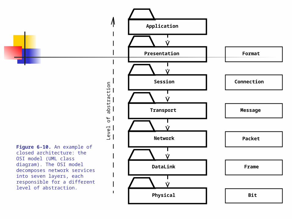
Closed architecture – layered but each layer depends only on one directly below it (e.g., ISO-OSI protocol stack or Unix OS)
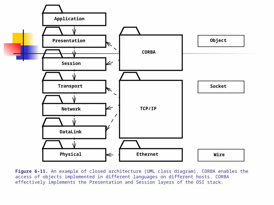
(See Fig 6.10 – in these, the OS provides middleware such as CORBA OMG, JavaRMI between upper the Application and Transport Layers and protocols like TCP/IP as middleware for the lower layers)
(See Fig 6.11)

F:SubsystemE:Subsystem G:Subsystem
D:SubsystemC:SubsystemB:Subsystem
A: Subsystem Layer 1 (Top)
Layer 2
Layer 3 (Bottom)
Figure 6-9. Subsystem decomposition of a system into three layers (UML object diagram). A subset from a layered decomposition that includes at least one subsystem from each layer is called a vertical slice. For example, the subsystems A, B, and E constitute a vertical slice, whereas the subsystems D and G do not.
Application
Presentation
Session
Transport
Network
DataLink
Physical
Frame
Packet
Bit
Connection
Format
MessageL
evel
of
abst
ract
ion
Figure 6-10. An example of closed architecture: the OSI model (UML class diagram). The OSI model decomposes network services into seven layers, each responsible for a different level of abstraction.
Application
Presentation
Session
Transport
Network
DataLink
Physical
Socket
CORBA
TCP/IP
Object
Ethernet Wire
Figure 6-11. An example of closed architecture (UML class diagram). CORBA enables the access of objects implemented in different languages on different hosts. CORBA effectively implements the Presentation and Session layers of the OSI stack.

6.0 SYSTEM DESIGN
6.3.4 Layers and Partitions – 1
Open architectures – E.g., Motif – user interface toolkit for X11 (Xlib for a window object, Xt for geometricl-object manipulation)
Users of a ‘window manager’ in Motif can bypass the upper layers and include lower layers like Xlib – fostering low coupling and integration, but limits reuse in case of changes in, e.g., Xlib
(See Fig 6.12)

Xlib
Xt
Motif
Application
Figure 6-12. An example of open architecture: the OSF/Motif library (UML class diagram, packages collapsed). Xlib provides low-level drawing facilities. Xt provides basic user interface widget management. Motif provides a large number of sophisticated widgets. The Application can access each of these layers independently.
6.0 SYSTEM DESIGN
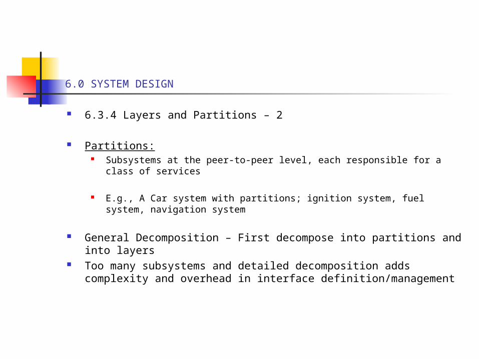
6.3.4 Layers and Partitions – 2
Partitions: Subsystems at the peer-to-peer level, each responsible for a class of
services
E.g., A Car system with partitions; ignition system, fuel system, navigation system
General Decomposition – First decompose into partitions and into layers
Too many subsystems and detailed decomposition adds complexity and overhead in interface definition/management
6.0 SYSTEM DESIGN
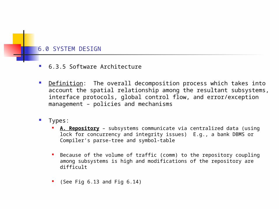
6.3.5 Software Architecture
Definition: The overall decomposition process which takes into account the spatial relationship among the resultant subsystems, interface protocols, global control flow, and error/exception management – policies and mechanisms
Types: A. Repository – subsystems communicate via centralized data (using lock
for concurrency and integrity issues) E.g., a bank DBMS or Compiler’s parse-tree and symbol-table
Because of the volume of traffic (comm) to the repository coupling among subsystems is high and modifications of the repository are difficult
(See Fig 6.13 and Fig 6.14)

Subsystem
Repository
createData()setData()getData()searchData()
Figure 6-13. Repository architecture (UML class diagram). Every subsystem depends only on a central data structure called the Repository. The Repository in turn, has no knowledge of the other Subsystems.

LexicalAnalyzer
SyntacticAnalyzerSemanticAnalyzer
CodeGenerator
SourceLevelDebugger SyntacticEditor
ParseTree SymbolTable
Compiler
Repository
Optimizer
Figure 6-14. An instance of the Repository architecture (UML Class diagram). A modern Compiler incrementally generates a ParseTree and a SymbolTable that can be later used by Debuggers and SyntaxEditors.

6.0 SYSEM DESIGN
6.3.5 Software Architecture - 1
B. Model-View-Controller (MVC) architecture – has three component subsysems:
A) Model subsystem for keeping domain knowledge/data B) View subsystem for visualizing/viewing the domain data C) Controller subsystem for managing user interactions with the system
The Model subsystem (like the repository architecture) holds the state of objects
The Controller subsystem holds the (user-personified) control objects for processing the models – the control flow
The View subsystem holds the boundary objects (for user visualization)
Communication among objects is via notify/subscribe protocols
(See Fig 6.15)
Controller
Model
subscriber
notifier
initiator
*
repository1
1
*
View
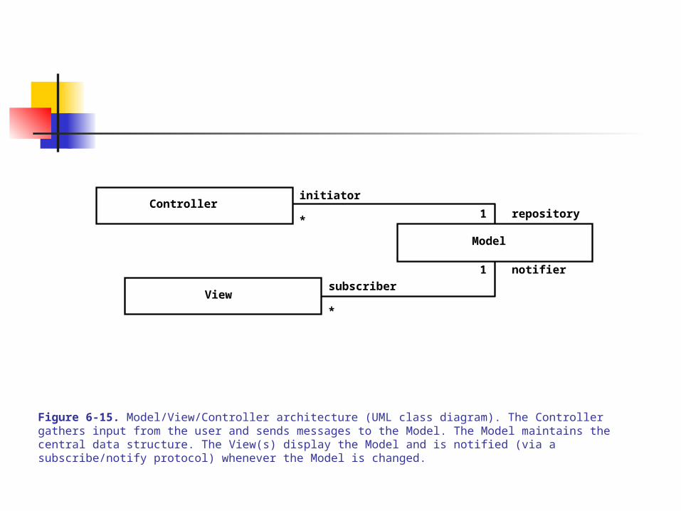
Figure 6-15. Model/View/Controller architecture (UML class diagram). The Controller gathers input from the user and sends messages to the Model. The Model maintains the central data structure. The View(s) display the Model and is notified (via a subscribe/notify protocol) whenever the Model is changed.

6.0 SYSTEM DESIGN
6.3.5 Software Architecture - 2
E.g., sequence of events in a MVC architecture –
Using a collaboration diagram (Fig 6-16 – flow of events among the objects)
And the corresponding effects – two views of a file-object, named 9DesignPatterns2.ppt (See Fig 6-17)
The subscription/notification protocols removes interdependencies among the objects in Model and View – allowing decoupling of their functions due to the frequent changes
A design tool for accomplishing this is – the Observer Pattern
MVC architecture is suitable for interactive systems and developing visualization tools

:Controller
:InfoView
:Model
2.User types new filename
1. Views subscribe to event
3. Request name change in model
4. Notify subscribers
5. Updated views
:FolderView
Figure 6-16. Sequence of events in the Model/View/Control architecture (UML collaboration diagram).

Figure 6-17. An example of MVC architecture. The “model” is the filename 9DesignPatterns2.ppt. One “view” is a window titled Comp-Based Software Engineering, which displays the contents of a folder containing the file 9DesignPatterns2.ppt. The other “view” is window called 9DesignPatterns2.ppt Info, which displays information related to the file. If the file name is changed, both views are updated by the “controller”.

6.0 SYSTEM DESIGN
6.3.5 Software Architecture - 4
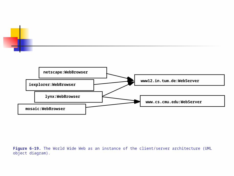
C. Client-Server architecture – C-S service request/response is via RPC (remote procedure call protocol)
Like the Repository model, the C-S server implements a ‘process’ that protects server data / programs (sort of localized in the server) and provides request service
E.g., a centralized database for an information system
E.g., a WWW with multiple user browser types and request from clients
C-S architecture is good for distributed systems design and modeling
(See Fig 6-18 and Fig 6.19)
Client
Server
service1()service2()
serviceN()…
**
requester provider
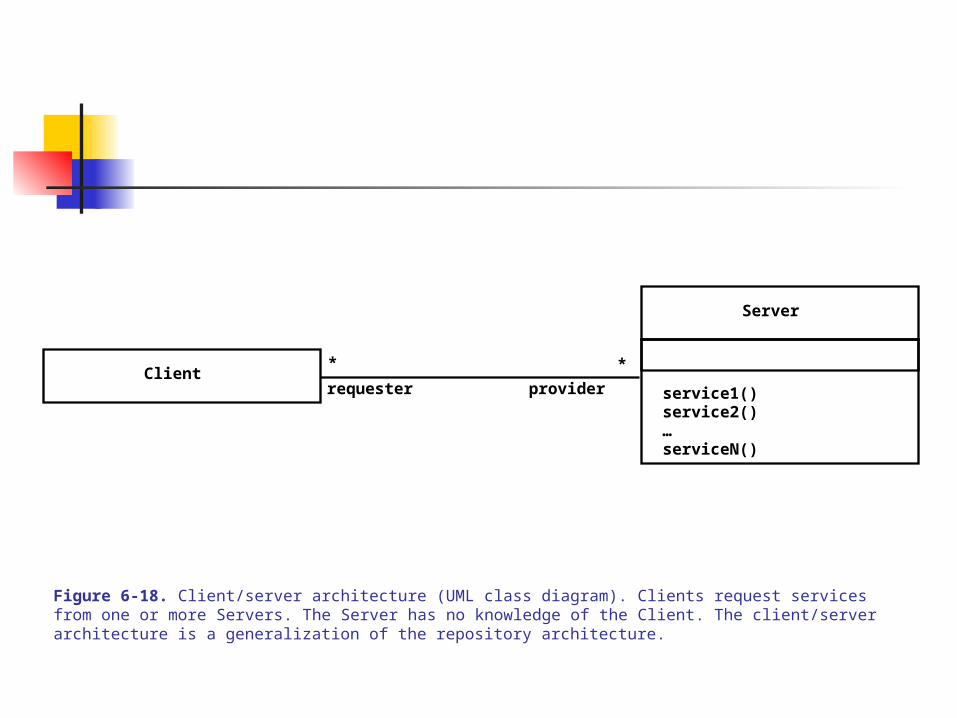
Figure 6-18. Client/server architecture (UML class diagram). Clients request services from one or more Servers. The Server has no knowledge of the Client. The client/server architecture is a generalization of the repository architecture.
netscape:WebBrowser
www12.in.tum.de:WebServer
www.cs.cmu.edu:WebServerlynx:WebBrowser
mosaic:WebBrowser
iexplorer:WebBrowser
Figure 6-19. The World Wide Web as an instance of the client/server architecture (UML object diagram).
6.0 SYSTEM DESIGN
6.3.5 Software Architecture -5
D. Peer-to-Peer architecture – a generalization of the C-S architecture: clients can become servers (from the other side) and servers can become clients similarly.
Useful, but difficult to design as it is susceptible to deadlocks and complex control flow
(See Fig 6-20 and Fig 6-21)

Peer
service1()service2()
serviceN()…
requester
provider
*
*
Figure 6-20. Peer-to-peer architecture (UML class diagram). Peers can request services from and provide services to other Peers.

application1:DBUser
database:DBMS
application2:DBUser
1. updateData
2. changeNotification
Figure 6-21. An example of peer-to-peer architecture (UML collaboration diagram). The database server can both process requests from and send notifications to applications.

6.0 SYSTEM DESIGN
6.3.5 Software Architecture - 6
E. Pipe and Filter architecture – a subsystem (serving as a filter) received input set, processes it internally and sends output set (through a pipe) to a ‘waiting’ subsystem (on the receiving end).
Concept is Unix OS environment – used for interprocess communication (automatic transformation of input data, automatic piping, and synchronized reception – without human intervention)
(See Fig 6-22 and Fig 6-23)

Pipe
input output
output input* 1
* 1
Filter
Figure 6-22. Pipe and filter architecture (UML class diagram). A Filter can have many inputs and outputs. A Pipe connects one of the outputs of a Filter to one of the inputs of another Filter.

% ps auxwww | grep dutoit | sort | more
dutoit 19737 0.2 1.6 1908 1500 pts/6 O 15:24:36 0:00 -tcshdutoit 19858 0.2 0.7 816 580 pts/6 S 15:38:46 0:00 grep dutoit
dutoit 19859 0.2 0.6 812 540 pts/6 O 15:38:47 0:00 sort
ps grep sort more
Figure 6-23. An instance of the pipe and filter architecture (Unix command and UML activity diagram).

6.0 SYSTEM DESIGN
6.3.6 UML Deployment Diagrams
Used for relating (connecting) component diagrams to hardware nodes. The components are self-contained run-time entities that provide services to other components
E.g. The Netscape browser (component) servicing the user (actor)
Notation: A node in a deployment diagram is a box, containing component icons, and interfaces between boxes are represented by dashed arrow
(See Fig 6-24 – more high level component nodes, revealing nothing about the interfaces used for communication or classes they contain)

:WebServer
myMac:Mac :UnixHost
:IExplorer
aPC:PC
:Database
:UnixHost
:Netscape
Figure 6-24. A UML deployment diagram representing the allocation of components to different nodes and the dependencies among components. Web browsers on PCs and Macs can access a WebServer that provides information from a Database.

6.0 SYSTEM DESIGN
6.3.6 UML Deployment Diagrams – 1
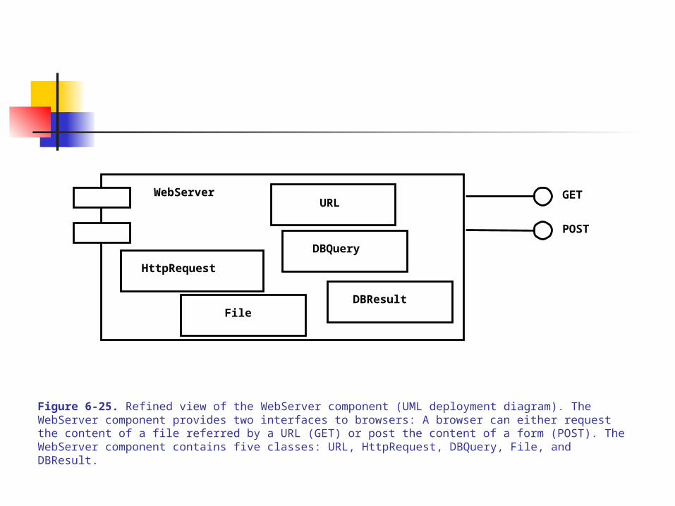
Fig 6-25 – Depicts a refined deployment diagram, showing the classes (no need to show associations/links, etc) and the interfaces/port for communication
GET
POST
HttpRequest
URL
File
WebServer
DBQuery
DBResult
Figure 6-25. Refined view of the WebServer component (UML deployment diagram). The WebServer component provides two interfaces to browsers: A browser can either request the content of a file referred by a URL (GET) or post the content of a form (POST). The WebServer component contains five classes: URL, HttpRequest, DBQuery, File, and DBResult.

6.0 SYSTEM DESIGN
6.4 System Design Activities
System design entails the transformation of the analysis model, together with the non-functional requirements and constraints in the RAD, into the design model toward the implementation
Example: ‘car driving’ plan to motivate the discussion of 8 main activities
Consider the ‘input’ Car Trip Analysis Model – collection of use cases, class diagram with data dictionary, and non-functional requirements
(See Fig 6-26 and Fig 6-27 and Fig 2-8) The non-functional requirements: - using a wireless modem for reliable connection to a PlanningService procider - accurate directions are given even on modem failure - modem connection time must be minimized - support replanning of the trip while connection is still available - PlanningService can support 50 drivers and 1000 trips

Location
Segment
Crossing
Direction
Destination
Trip
RouteAssistant PlanningService
Figure 6-28. Analysis model for the MyTrip route planning and execution.
6.0 SYSTEM DESIGN
6.4 System Design Activities – 1
A. Identifying design goals:
From the non-functional requirements: reliability, fault tolerance, connectivity, security, number of drivers and trips, replanning/modifiability, cost-effectiveness.
Others: connection time or response time, performance, maintenance (upkeep of driving data), etc., which are gleaned from the RAD or application domain
Criteria and goals may be conflicting – requires compromises, trade-offs and optimization
(See Table 6-1 to Table 6-6)

6.0 SYSTEM DESIGN
6.4 System Design Activities - 2
B. Identifying Subsystems: Similar application of Abbott’s heuristics to identifying objects Requires subsystem decomposition, mergers, and additions – iterative process Initial decomposition is from the functional and object models (use cases –
base use cases, shared use cases, extended/included use cases) and the classes.
Key: grouping use cases and classes into related entities as ‘packages’ of subsystems
Heuristics for Identifying subsystems: Assign objects identified in one use case into the same subsystem Create a dedicated subsystem for ‘data moving’ objects in the system Use a fewer number of links/associations crossing subsystem boundaries Objects in the same subsystem must be functionally related

6.0 SYSTEM DESIGN
6.4 System Design Activities – 3
C. Encapsulating subsystems – Packages of subsystems reduce complexity or minimize dependencies
among classes
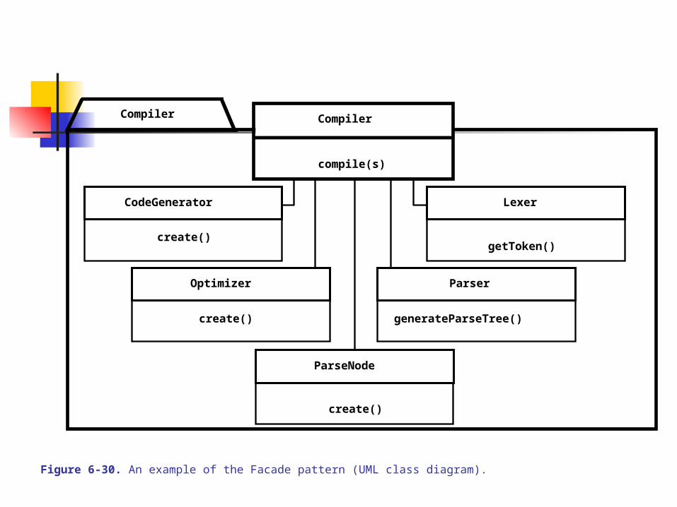
Encapsulating subsystems inside a ‘front-end’ package, called a Façade, further hides the internals of the classes – making the internals only accessible by the façade. The outside world can get to these classes only via public services/interface provided in the façade. This design strategy uses the Façade Pattern via encapsulation
E.g., Encapsulating the ‘Compiler’ subsystem in a Façade, by providing an interface service routine, compile(s).
(See Fig 6-30)
Compiler
compile(s)
create()
getToken()
CodeGenerator
create()
generateParseTree()create()
Compiler
Optimizer
Lexer
Parser
ParseNode
Figure 6-30. An example of the Facade pattern (UML class diagram).

6.0 SYSTEM DESIGN
6.4 System Design Activities – 4
4. Mapping Subsystems to Processors and Components
Selecting a hardware configuration and a platform Allocating/assigning subsystems to different processors, and design comm
support between subsystems Underlying processors are modeled as nodes in Deployment Diagrams Underlying virtual machines (the OS’s, the DBMS’s, Networks), compatible
with the processors, but the selection could be constrained by cost, processor-type, etc.
E.g., For the MyTrip problem, select two processors (nodes) – an Internet host and an onboard (embedded in the car) processor, the Unix-Netscape for the host, and some RTOS-Explorer for the onboard
(See Fig 6-31)
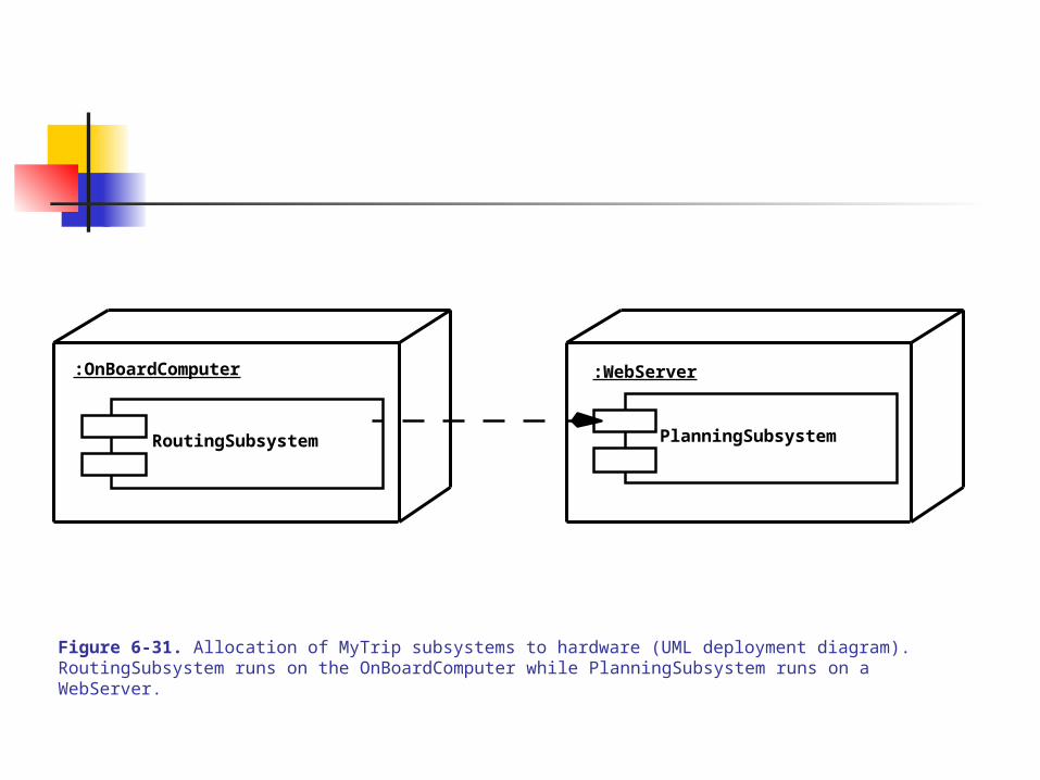
RoutingSubsystem PlanningSubsystem
:OnBoardComputer :WebServer
Figure 6-31. Allocation of MyTrip subsystems to hardware (UML deployment diagram). RoutingSubsystem runs on the OnBoardComputer while PlanningSubsystem runs on a WebServer.
6.0 SYSTEM DESIGN
6.4 System Design Activities – 5
Allocating objects/subsystems to nodes – done after selecting the operating environ
Object/subsystem assignment exposes missing subsystems, e.g., for data movement
E.g., in the MyTrip, a CommunicationSubsystem is need to support the comm between the wireless modem and all other objects/subsystems
There is the need for surrogate subsystems: SegmentProxy- one that takes care of info pertaining to a segment (of trip) and TripProxy - another that helps in planning a trip. These are needed inside the RoutingSubsystem to act as Proxies on behalf of the two subsystems in the PlanningSubsystem. The two proxies communicate with the CommicationSubsystem.
The Proxy Design Pattern is used to create proxy subsystems as surrogates of others without duplicating full functionality
(See Fig 6-32)

TripLocation
PlanningService
SegmentCrossing
RouteAssistant
Direction
Destination
TripProxy
SegmentProxy
PlanningSubsystem
Message
Connection
CommunicationSubsystem
RoutingSubsystem
Figure 6-32. Revised design model for MyTrip (UML Class diagram, associations omitted for clarity).
6.0 SYSTEM DESIGN
6.4 System Design Activities – 6
Encapsulating Existing/Legacy and Off-the-Shelf Components – Need to incorporate existing systems and reuse of off-the-shelf components
to reduce design/development time and costs
Encapsulating also hides the internals of the existing component, further decoupling the system under construction from the existing
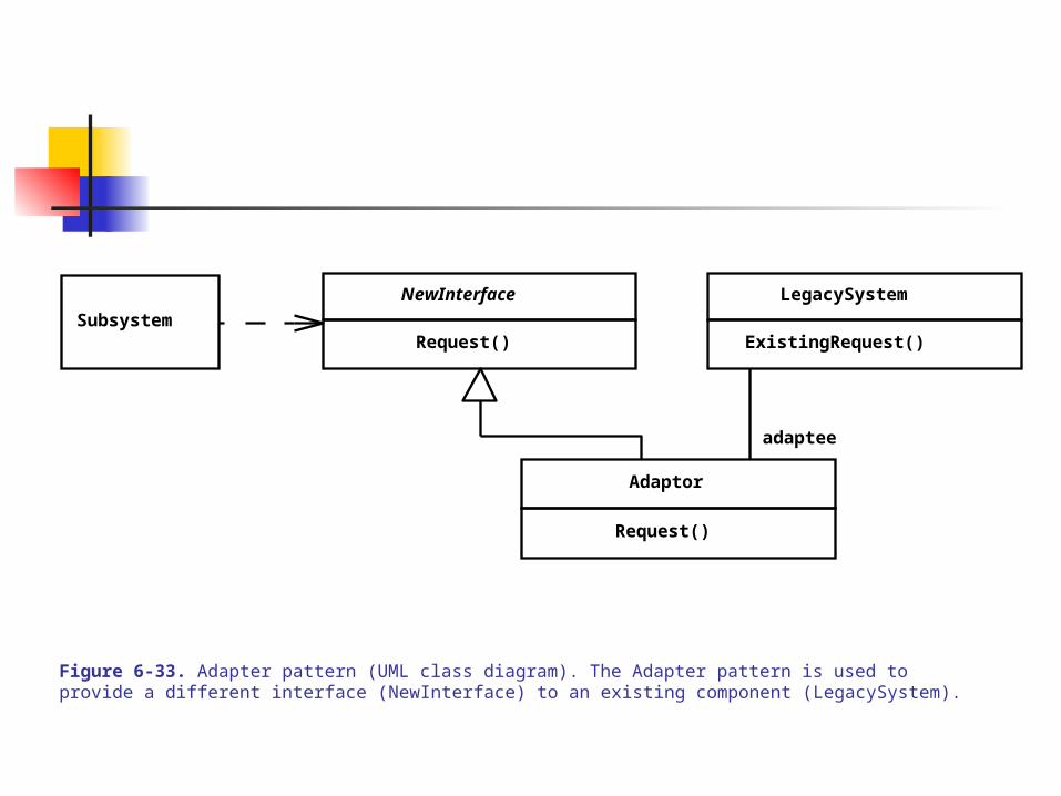
The ‘integrator / glue’ is called the Adapter Pattern or Wrapper
Wrappers are useful in developing e.g., communication protocol glues for distributed applications developed in different languages or that use different protocols (e.g., CORBA environment)
(See Fig 6-33 and Fig 6-34)
NewInterface
Request()
adaptee
LegacySystem
ExistingRequest()
Adaptor
Request()
Subsystem
Figure 6-33. Adapter pattern (UML class diagram). The Adapter pattern is used to provide a different interface (NewInterface) to an existing component (LegacySystem).
6.0 SYSTEM DESIGN
6.4 System Design Activities - 7
5. Defining Persistent Data Stores – preserving data values consistently over time
The kind DB system and its DBMS for storage/processing/retrieval impacts system decomposition, control strategy, and concurrency management
E.g., in the MyTrip problem, a small file in RoutingSubsystem will hold trip-files on short-term basis on the onboard computer, while the PlanningSubsystem will hold persistent trip-files in a DB over time
Persistent data are kept because it may be costly to recalculate, otherwise don’t
Factors to consider in selecting DB type: complex queries, data size/space, management, use of flat files, Relational DB, OO database (see p. 205 – tradeoffs)
(See Fig 6-35)

PlanningSubsystem
MapDBStoreSubsystem
TripFileStoreSubsystem
RoutingSubsystem
CommunicationSubsystem
Figure 6-35. Subsystem decomposition of MyTrip after deciding on the issue of data stores (UML class diagram, packages collapsed for clarity).

6.0 SYSTEM DESIGN
6.4 System Design Activities – 8
Encapsulating data stores – once a DB is selected provide an ‘interface,’ a bridge to the DB which will hide the vendor-specific services and data layout. The interface will decouple your classes/subsystems from the DB
The ‘abstract’ interface available to the client (your program) and corresponding ‘abstract’ implementation, which maps requests/queries to specific DBMS queries, are need.
The AbstractInterface and AbstractImplementor classes are supported by the Bridge Pattern [E.g., ODBC and JDBC provide abstractions to relational databases]
(See Fig 6-36 and Fig 6-37)

RefinedAbstraction
Implementorimp
ConcreteImplementorA
ConcreteImplementorB
providesAbstractionSubsystem
Figure 6-36. Bridge pattern (UML class diagram).

ODBC ImplementationODBCimp
Oracle ODBCDriver
DB2 ODBCDriver
Informix ODBCDriver
Figure 6-37. Bridge pattern for abstracting database vendors (UML class diagram). Removing the dependency from database vendors from the systems provides more flexibility.
6.0 SYSTEM DESIGN
6.4 System Design Activities – 9
6. Defining Access Control Multiple actor access to functionality and shared data – requires protected or
restricted access Access control is modeled using different use cases during the analysis
phase Access control is modeled by focusing on the object model – determining
which actor accesses which objects and creating an ‘authentication’ for access control and ‘encryption’ to encrypt traffic data for security
(See Table 6-7 – expanded to include authentication-of-drivers and traffic-encryption concerns in the design model)
General implementation strategy: develop an access matrix of user/object, where the cells indicate the permissible operations, or access rights – classical in OS, DB, Network applications
(See Table 6-8)

6.0 SYSTEM DESIGN
6.4 System Design Activities – 10
Access control matrix representations – the select method can impact performance
1) global access control – (actor, class, operation)-tuple in each cell 2) access control list – (actor, operation)-pair for each class in the list 3) capability list – (class, operation)-pair for each actor in the list
Subclassing under the access-control-list method can discriminate actor access
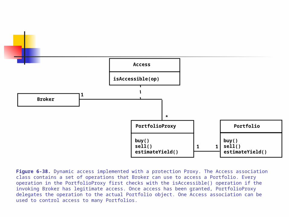
Static access control – typically implemented as access matrix Dynamic access control – supports dynamically assigned roles to actors or
objects, and can be modeled using the Proxy Pattern
(See Fig 6-38 – dynamic assignment of portfolios to brokers)
Portfolio
buy()sell()estimateYield()
1
1
*
1
Broker
buy()sell()estimateYield()
Access
isAccessible(op)
Figure 6-38. Dynamic access implemented with a protection Proxy. The Access association class contains a set of operations that Broker can use to access a Portfolio. Every operation in the PortfolioProxy first checks with the isAccessible() operation if the invoking Broker has legitimate access. Once access has been granted, PortfolioProxy delegates the operation to the actual Portfolio object. One Access association can be used to control access to many Portfolios.
PortfolioProxy

6.0 SYSTEM DESIGN
6.4 System Design Activities – 11
Authentication – verifying association between an actor/subsystem and the system. Typical mechanisms: name, ID, password (with encryption), smart cards, fingerprints
Encryption – preventing unauthorized access by converting plaintext (message) to a ciphertext (encrypted). Need a key and an algorithm to decipher (decrypt) the ciphertext.
Encapsulating access control If using off-the-shelf or vendor-supplied algorithms, policies, and mechanisms –
be careful of Trojan Horse entrapment (no escape hatches hidden in the product).
General solution – develop an encapsulation of general algorithms, with an abstract interface, for several concrete algorithms using the Strategy Pattern
(See Fig 6.40)

Message
getBlock()
IDEA
IDEA_Vendor_A IDEA_Vendor_B
encrypt(key, block)decrypt(key, block)
Context class
Strategy class
ConcreteStrategy classes
Figure 6-40. An example of a Strategy pattern encapsulating multiple implementation of the IDEA encryption algorithm (UML class diagram). The Message and IDEA classes cooperate to realize the encryption of plain text. The selection of an implementation can be done dynamically.
6.0 SYSTEM DESIGN
6.4 System Design Activities
7. Designing the Global Control Flow
Which operations to execute and the order/sequence of operations In OO (UML) methodologies, it is the actor’s initiation or passage of time
During analysis, objects are assumed to interact with each other and timing and processor on which they are interacting is not a big issue
During design, objects’ behavior and on which processors (assigned) they would run and timing issues become important

6.0 SYSTEM DESIGN
6.4 System Design Activities
Mechanisms for implementing Control Flow:
1) Procedure-driven: operations wait on input from actor – not suitable for OO design since control flow is distributed in an object-space and the other is not determinable
2) Event-driven: a main program initiates the external event to activate objects in the system (which are waiting on that event) – centralizes control but hard to implement in multi-step (nested conditions) sequences
3) Threads: concurrent version of procedure-driven, where several operations (threads of execution) wait on different event (input arrival) and behavior according – they respond to input-stimuli from the actor. Hard to debug and create repeatable test cases and degenerates to non-deterministic control flow
(See Fig. 6-41, Fig 6-42, and Fig 6-43)

6.0 SYSTEM DESIGN
6.4 System Design Activities
Issues: A) procedure-driven is good for unit testing (using test-drivers) subsystems
B) Event-driven (debugging tools) and interface support are more matured than threads control flow, which currently lacks such tools. (Event-driven flow can influence design rationale and choices, e.g., in embedded systems.)
C) Control objects are used to describe the control flow (or software architecture) of the system. Control objects receive ‘stimuli’, store state on temporary basis, and issue signals to activate other control objects, entity objects, and boundary objects
D) Good idea to allow one control object to start up control flow in a use case

6.0 SYSTEM DESIGN
6.4 System Design Activities
Encapsulating Control Flow Control flow is determined by the sequence of stimuli/inputs to the various
control objects waiting on the inputs. The objects request the input – and to decouple the requesting control objects from the service objects (the input handlers), the request satisfaction must be assigned to separate ‘command objects.’
The decoupling can be achieved by using the Command Pattern, which effectively centralizes control flow in control objects and not in boundary or entity objects
The Command abstract class defines the order of execution of the commands (sequence of operations based on order of input arrivals).
The Command abstract class issues the ‘concrete/specific’ commands using the ConcreteCommand class to satisfy the control flow (or order)
(See Fig 6-44 and Fig 6-45)

User
ConcreteCommand1
execute()
Calling Subsystem
invokes
ConcreteCommand2
execute()
Receiver
action2()action1()
execute()
Command
execute()
Figure 6-44. Command pattern (UML class diagram).This pattern enables the encapsulation of control such that user requests can be treated uniformly, independent of the specific request.

execute()
MenuItem
PasteCommand
execute()
Command
execute()
Menu
Application
* *
copy()paste()
Document
execute()
CopyCommand
Figure 6-45. An example of a Command pattern (UML class diagram). In this example, menu items and operations on documents are decoupled. This enables us to centralize control flow in the command objects (CopyCommand and PasteCommand) instead of spreading it across boundary objects (MenuItem) and entity objects (Document).
6.0 SYSTEM DESIGN
6.4 System Design Activities
8. Identifying Boundary Conditions Focus is on how the system is initiated/started, shutdown/closed, handling
exceptions or failures (software or hardware)
E.g., for the MyTrip systems – how maps get into onboard computer, how to load the software to onboard computer, how data (route into, schedules, etc.) get into or modified in the computer, …
To complete the design, go back to define new use cases to “include” the missing boundary objects – a set of use cases which constitutes the Administrative Subsystem and other <<include>> use cases for common functions
Modify the MyTrip analysis model to include the Administrative Subsystem, and modify the MapDBStoreSubsystem use case to reflect ‘boundary’ conditions of shutdown, data corruption, data consistency check, etc.
(See Fig 6-46, Fig 6-47, and Fig 6.48)
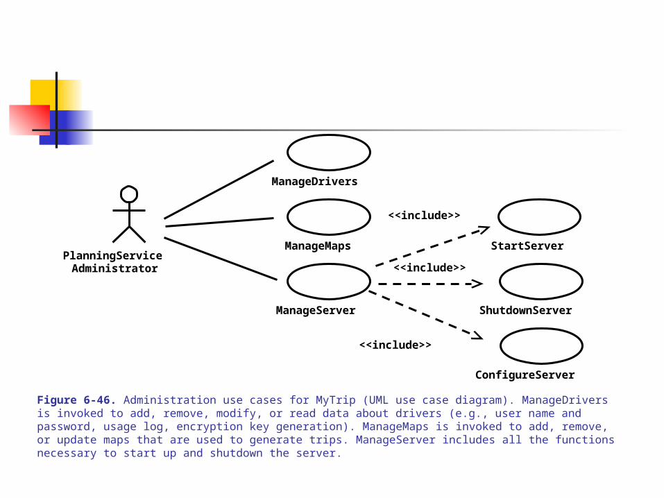
PlanningService
ManageDrivers
ManageMaps
ManageServer
Administrator
StartServer
ShutdownServer
ConfigureServer
<<include>>
<<include>>
<<include>>
Figure 6-46. Administration use cases for MyTrip (UML use case diagram). ManageDrivers is invoked to add, remove, modify, or read data about drivers (e.g., user name and password, usage log, encryption key generation). ManageMaps is invoked to add, remove, or update maps that are used to generate trips. ManageServer includes all the functions necessary to start up and shutdown the server.

6.0 SYSTEM DESIGN
6.4 System Design Activities
Exceptions and Handling –
Causes a) user error – wrong input (range or constraint error), b) hardware failure – power fail, surge, worn-out part, network failure; c) software error – design/programming error
Exception Handling – mechanisms for handling and correcting the error without total shutdown

6.0 SYSTEM DESIGN
6.4 System Design Activities
9. Anticipating Change
System decomposition into subsystem foster low coupling (minimal impact on changes) and reduces complexity
System decomposition must allow flexible software architecture for future changes Anticipating changes and design techniques/methodologies to deal with them:
1) new vendor/technology – replacements in response to growth, performance, dynamics
2) new implementation – efficiency, performance, new non-functional requirements 3) new views – usability issues and new users/perceptions of system 4) new complexity of application domain – deployed systems that generates new
goals
(See Fig 6.49)
6.0 SYSTEM DESIGN
6.4 System Design Activities10. Reviewing the Design
Done between project manager and development team (without user/client) The process may involve peer reviews (e.g., developers from different project)
Some of the factors to observe during review A) traceability/correctness – mapping the design model to the analysis model B) completeness – all boundary conditions, missing use cases/subsystems, etc. C) consistent – no contradictions, prioritized goals, addressed non-func req,
naming D) realistic – feasibility of supporting technologies, reliability/performance
achievable E) readable – subsystem names, relating entity names –
functionality/phenomena
6.0 SYSTEM DESIGN
6.5 Managing System Design
1. The Design Document (SDD) – baselined for object design step (p.222)
Include a section on how design communication was handled/documented; communication modes and mechanisms used in the system design process
2. Assigning Responsibilities – an architect architecture team document editor, configuration manager, reviewer
Related Documents


![future practice: parametric design catalog€¦ · [model catalog] design process prototype testing [re-design] 1. model development [ ] client’s scope: land acquisition site work](https://static.cupdf.com/doc/110x72/6039114470e2596d0f79389b/future-practice-parametric-design-catalog-model-catalog-design-process-prototype.jpg)
