Design Process of Serpentine Channel Documentation on the design of a basic injector-separation channel model design

Design Process of Serpentine Channel Documentation on the design of a basic injector-separation channel model design.
Dec 22, 2015
Welcome message from author
This document is posted to help you gain knowledge. Please leave a comment to let me know what you think about it! Share it to your friends and learn new things together.
Transcript

Design Process of Serpentine Channel
Documentation on the design of a basic
injector-separation channel model design
Design that will be build
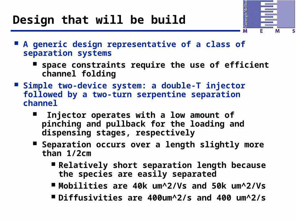
A generic design representative of a class of separation systems
space constraints require the use of efficient channel folding
Simple two-device system: a double-T injector followed by a two-turn serpentine separation channel
Injector operates with a low amount of pinching and pullback for the loading and dispensing stages, respectively
Separation occurs over a length slightly more than 1/2cm Relatively short separation length because the
species are easily separated Mobilities are 40k um^2/Vs and 50k um^2/Vs Diffusivities are 400um^2/s and 400 um^2/s

Final Design Flow Direction
This is the electric field flow direction
Creating a new Library
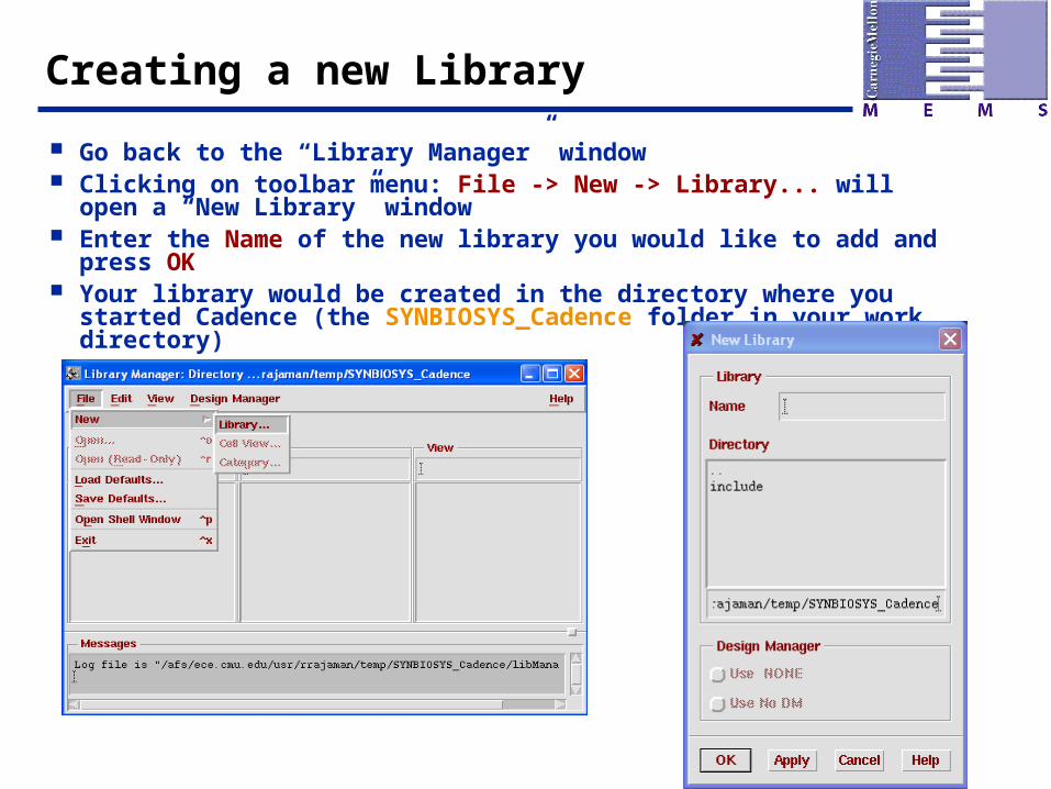
Go back to the “Library Manager” window Clicking on toolbar menu: File -> New -> Library... will open a “New
Library” window Enter the Name of the new library you would like to add and press OK Your library would be created in the directory where you started
Cadence (the SYNBIOSYS_Cadence folder in your work directory)
Back to the Library Manager
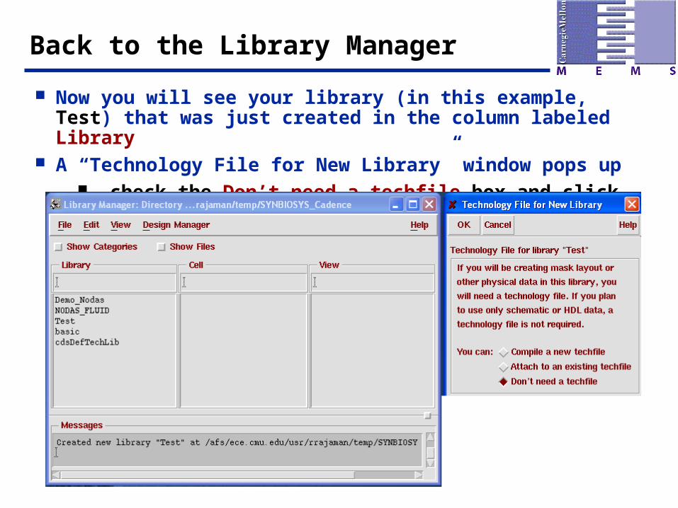
Now you will see your library (in this example, Test) that was just created in the column labeled Library
A “Technology File for New Library” window pops up check the Don’t need a techfile box and click OK
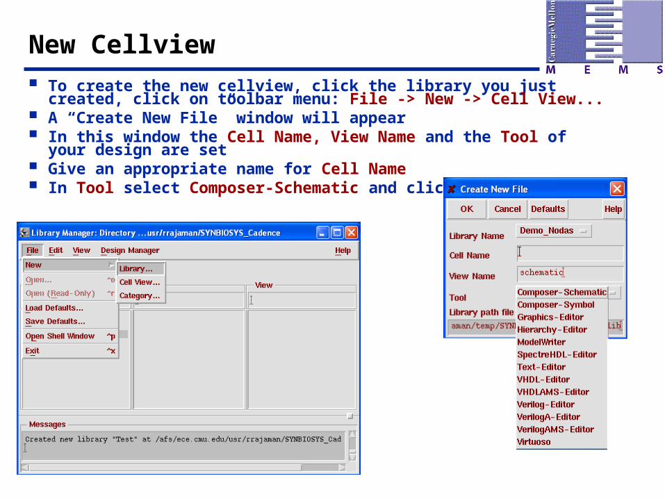
New Cellview To create the new cellview, click the library you just created, click on
toolbar menu: File -> New -> Cell View... A “Create New File” window will appear In this window the Cell Name, View Name and the Tool of your design
are set Give an appropriate name for Cell Name In Tool select Composer-Schematic and click OK
The Editor Window
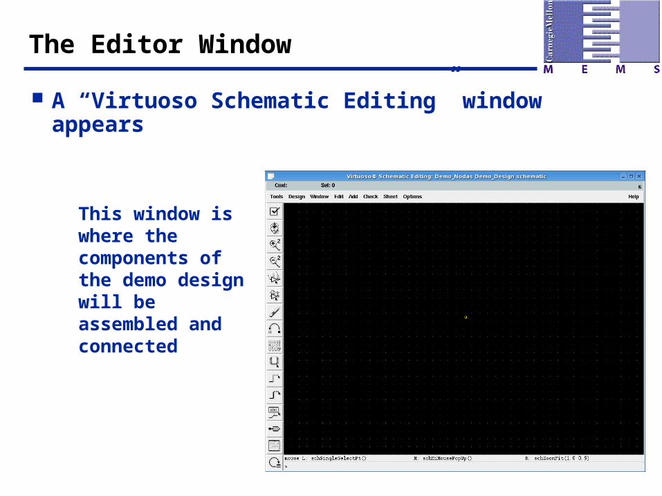
A “Virtuoso Schematic Editing” window appears
This window is where the components of the demo design will be assembled and connected
Adding an Instance
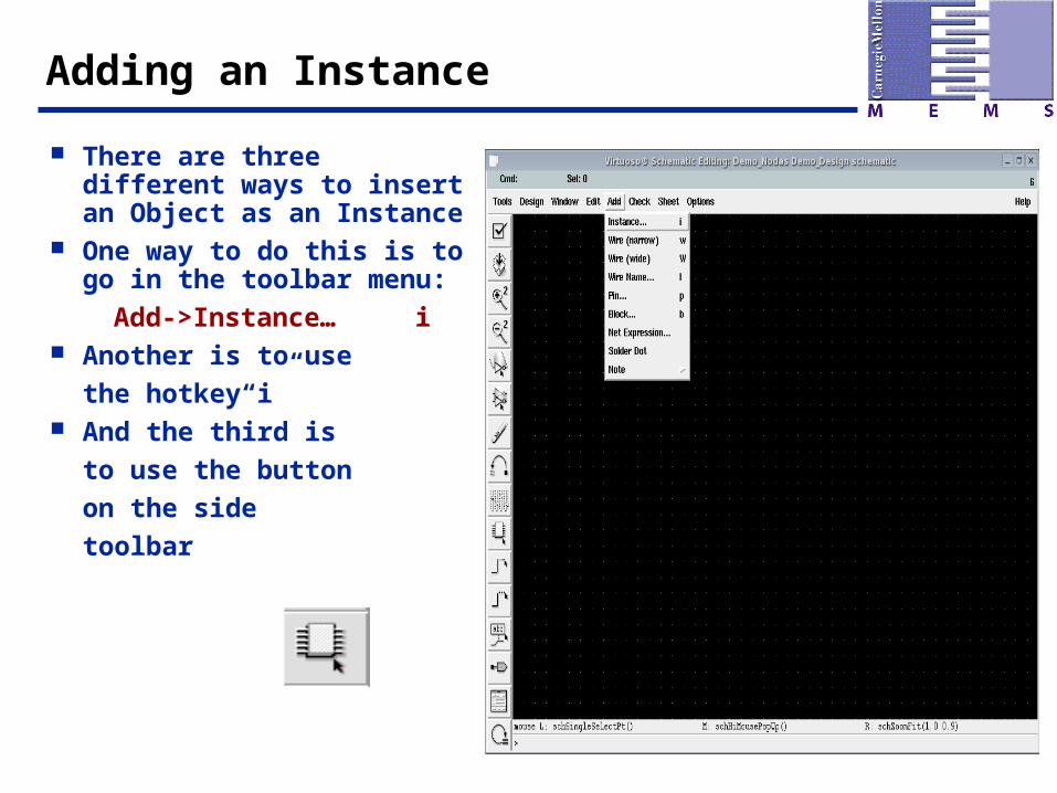
There are three different ways to insert an Object as an Instance
One way to do this is to go in the toolbar menu:
Add->Instance… i Another is to use
the hotkey“i” And the third is
to use the button
on the side
toolbar
Selecting the Object
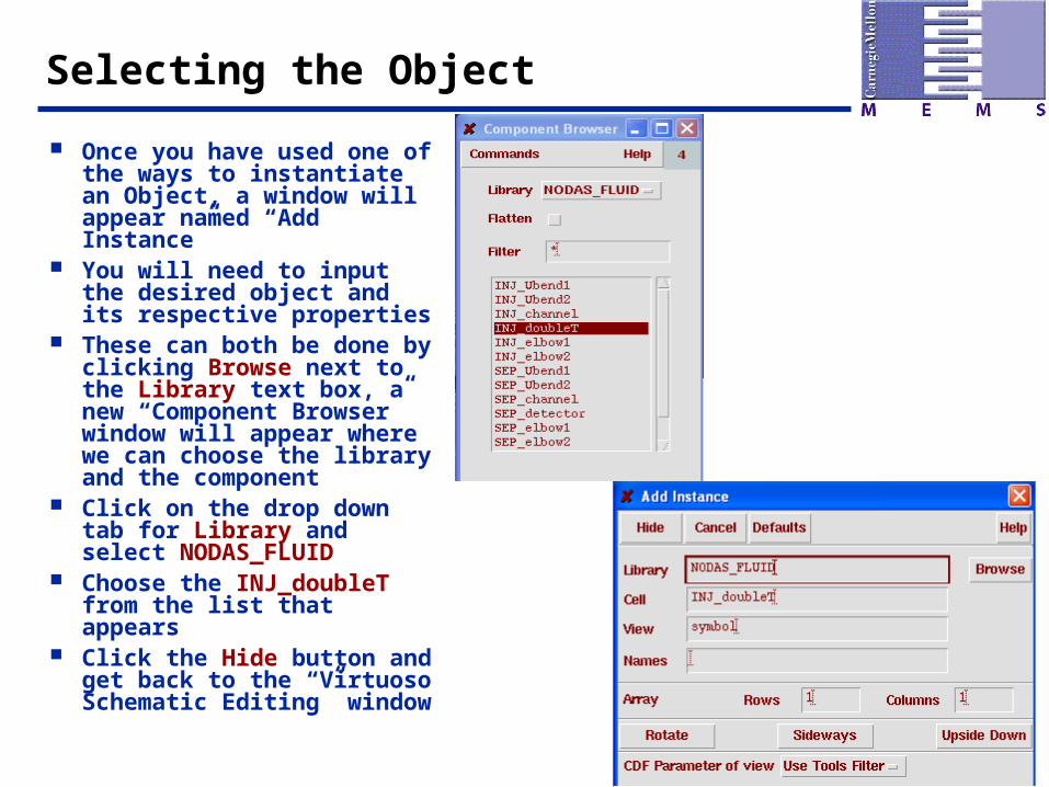
Once you have used one of the ways to instantiate an Object, a window will appear named “Add Instance”
You will need to input the desired object and its respective properties
These can both be done by clicking Browse next to the Library text box, a new “Component Browser” window will appear where we can choose the library and the component
Click on the drop down tab for Library and select NODAS_FLUID
Choose the INJ_doubleT from the list that appears
Click the Hide button and get back to the “Virtuoso Schematic Editing” window
Placing the Instance
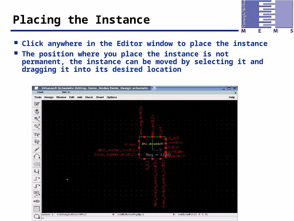
Click anywhere in the Editor window to place the instance The position where you place the instance is not permanent,
the instance can be moved by selecting it and dragging it into its desired location
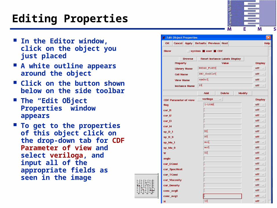
Editing Properties
In the Editor window, click on the object you just placed
A white outline appears around the object
Click on the button shown below on the side toolbar
The “Edit Object Properties” window appears
To get to the properties of this object click on the drop-down tab for CDF Parameter of view and select veriloga, and input all of the appropriate fields as seen in the image
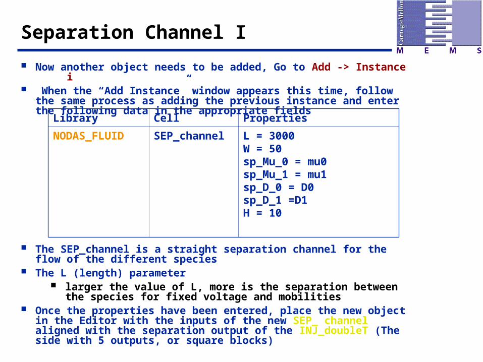
Separation Channel I
Now another object needs to be added, Go to Add -> Instance i When the “Add Instance” window appears this time, follow the same
process as adding the previous instance and enter the following data in the appropriate fields
The SEP_channel is a straight separation channel for the flow of the different species
The L (length) parameter larger the value of L, more is the separation between the species
for fixed voltage and mobilities Once the properties have been entered, place the new object in the Editor
with the inputs of the new SEP_ channel aligned with the separation output of the INJ_doubleT (The side with 5 outputs, or square blocks)
Library Cell Properties
NODAS_FLUID SEP_channel L = 3000W = 50sp_Mu_0 = mu0sp_Mu_1 = mu1sp_D_0 = D0sp_D_1 =D1H = 10
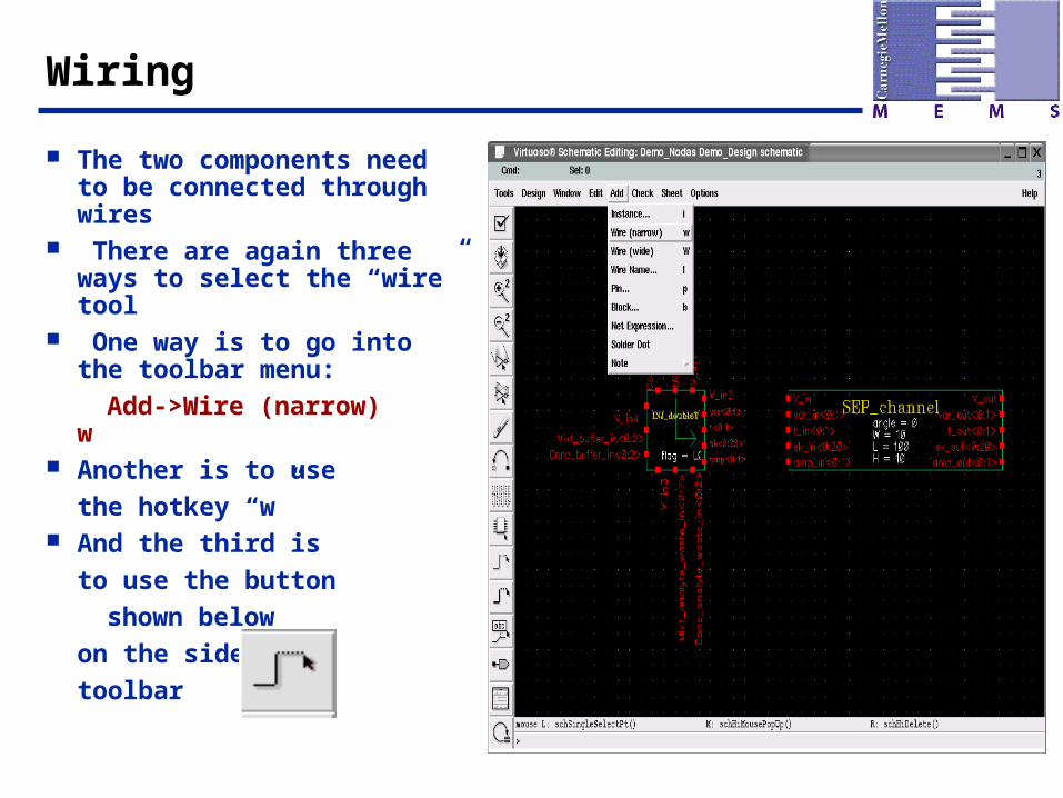
Wiring
The two components need to be connected through wires
There are again three ways to select the “wire” tool
One way is to go into the toolbar menu:
Add->Wire (narrow) w Another is to use
the hotkey “w” And the third is
to use the button
shown below
on the side
toolbar
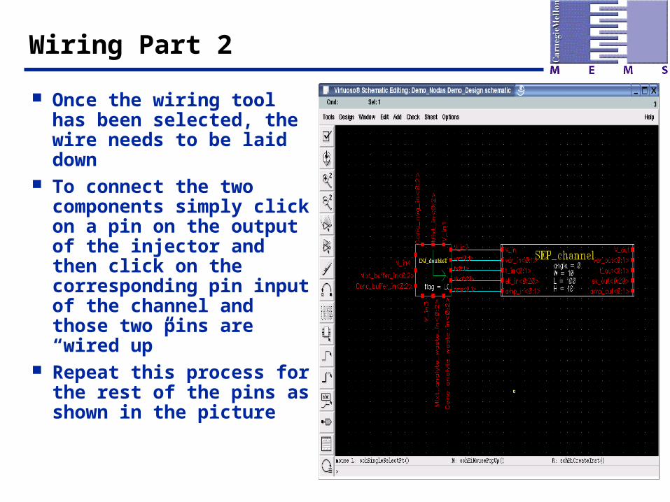
Wiring Part 2
Once the wiring tool has been selected, the wire needs to be laid down
To connect the two components simply click on a pin on the output of the injector and then click on the corresponding pin input of the channel and those two pins are “wired up”
Repeat this process for the rest of the pins as shown in the picture
Another Way to Wire
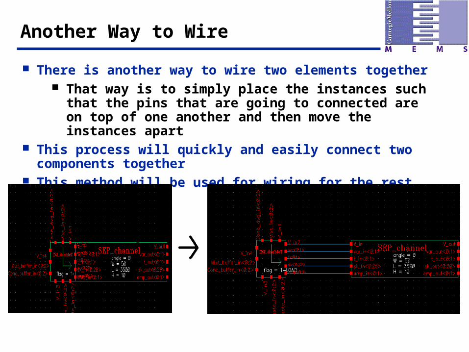
There is another way to wire two elements together That way is to simply place the instances such that the
pins that are going to connected are on top of one another and then move the instances apart
This process will quickly and easily connect two components together
This method will be used for wiring for the rest of this tutorial

The Detector
Instantiate a new object with the following properties:
Once the detector has been placed in the Editor window, wire it to the channel as shown
The detector is placed at different stages in the separation channel to monitor the flow of the species
Library Cell
NODAS_FLUID SEP_detector sp_Mu_0 = mu0, sp_Mu_1 = mu1, sp_D_0 = D0, sp_D_1 = D1
Adding Pins
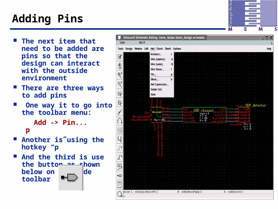
The next item that need to be added are pins so that the design can interact with the outside environment
There are three ways to add pins
One way it to go into the toolbar menu:
Add -> Pin... p Another is using the
hotkey “p” And the third is use the
button as shown below on the side toolbar
Pins Part 1
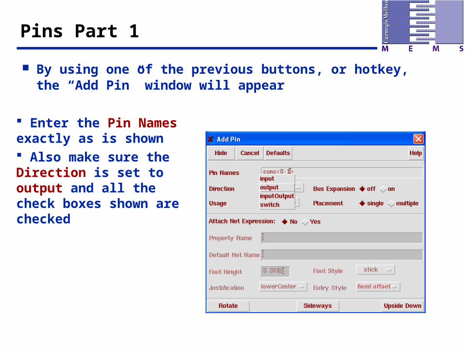
By using one of the previous buttons, or hotkey, the “Add Pin” window will appear
Enter the Pin Names exactly as is shown Also make sure the Direction is set to output and all the check boxes shown are checked

Pins Part 2
The next step is to place the pin on the Editor

Rotate Part 1
The Pin is facing to the right To clean up the look, the pin
can be rotated to be pointing straight down
There are three ways to Rotate Items
One way it to go into the toolbar menu:
Edit -> Rotate r Another is using the hotkey “r”
Rotate Part 2
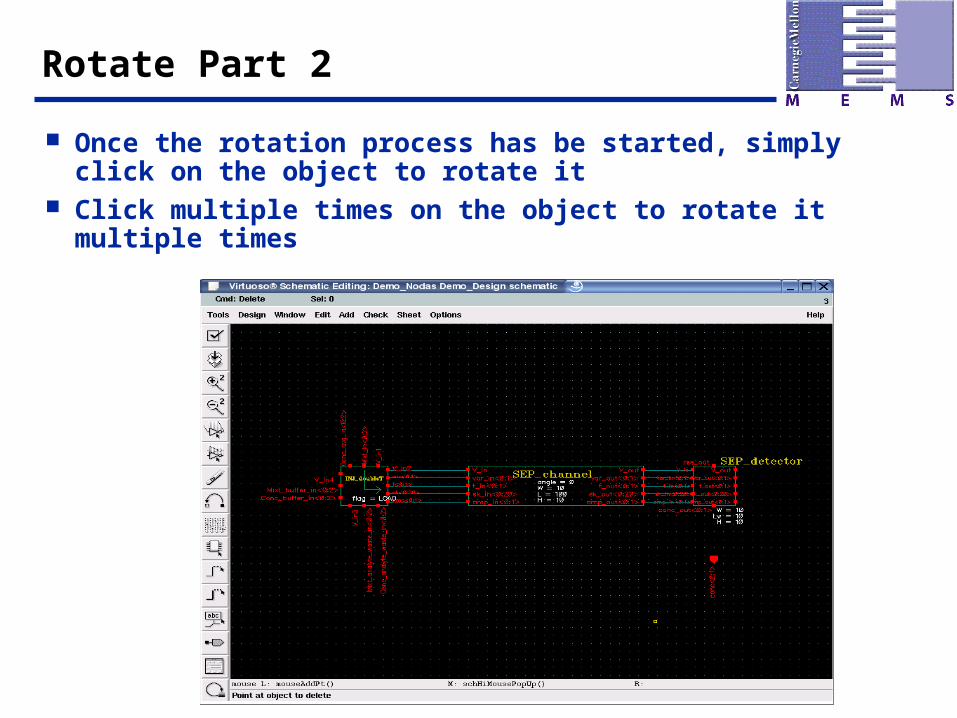
Once the rotation process has be started, simply click on the object to rotate it
Click multiple times on the object to rotate it multiple times
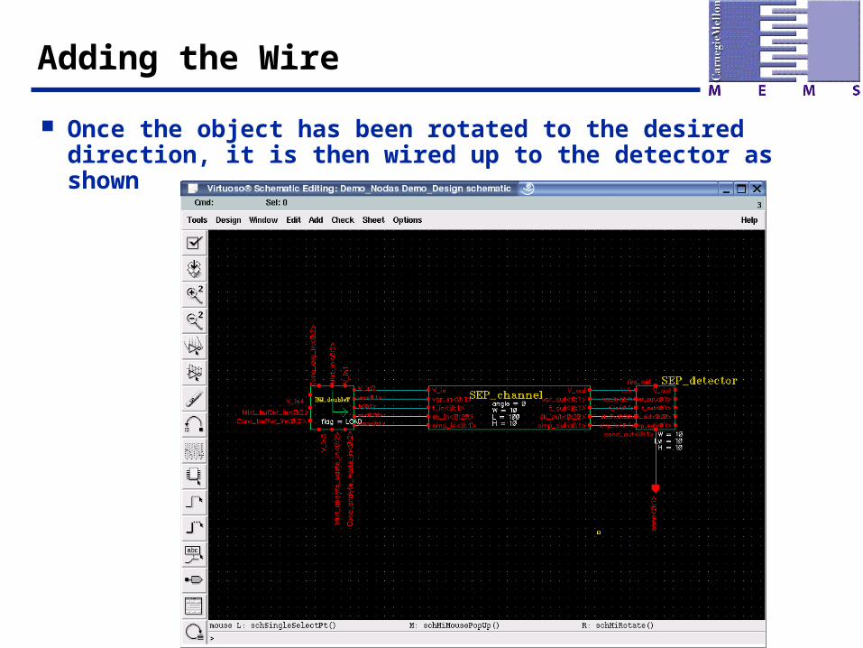
Adding the Wire
Once the object has been rotated to the desired direction, it is then wired up to the detector as shown
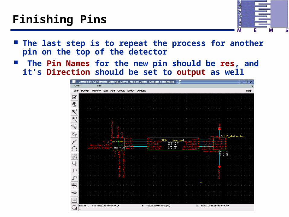
Finishing Pins
The last step is to repeat the process for another pin on the top of the detector
The Pin Names for the new pin should be res, and it’s Direction should be set to output as well
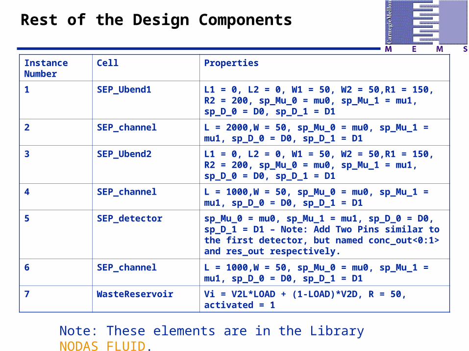
Rest of the Design Components
Instance Number
Cell Properties
1 SEP_Ubend1 L1 = 0, L2 = 0, W1 = 50, W2 = 50,R1 = 150, R2 = 200, sp_Mu_0 = mu0, sp_Mu_1 = mu1, sp_D_0 = D0, sp_D_1 = D1
2 SEP_channel L = 2000,W = 50, sp_Mu_0 = mu0, sp_Mu_1 = mu1, sp_D_0 = D0, sp_D_1 = D1
3 SEP_Ubend2 L1 = 0, L2 = 0, W1 = 50, W2 = 50,R1 = 150, R2 = 200, sp_Mu_0 = mu0, sp_Mu_1 = mu1, sp_D_0 = D0, sp_D_1 = D1
4 SEP_channel L = 1000,W = 50, sp_Mu_0 = mu0, sp_Mu_1 = mu1, sp_D_0 = D0, sp_D_1 = D1
5 SEP_detector sp_Mu_0 = mu0, sp_Mu_1 = mu1, sp_D_0 = D0, sp_D_1 = D1 – Note: Add Two Pins similar to the first detector, but named conc_out<0:1> and res_out respectively.
6 SEP_channel L = 1000,W = 50, sp_Mu_0 = mu0, sp_Mu_1 = mu1, sp_D_0 = D0, sp_D_1 = D1
7 WasteReservoir Vi = V2L*LOAD + (1-LOAD)*V2D, R = 50, activated = 1
Note: These elements are in the Library NODAS_FLUID.

After Adding The New Instances
This is how your instances should be placed and connected
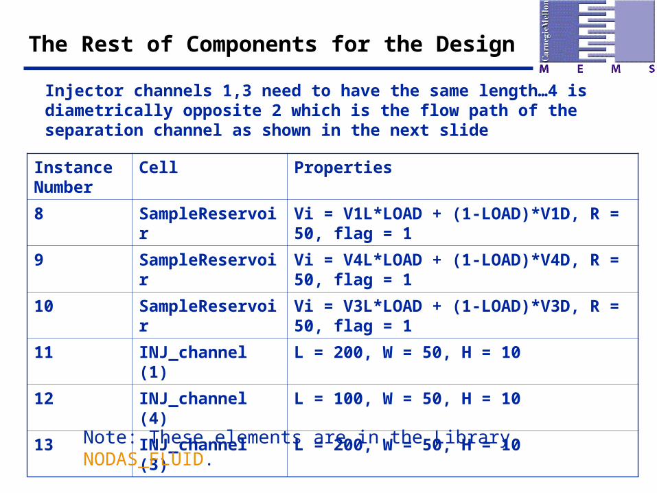
The Rest of Components for the Design
Instance Number
Cell Properties
8 SampleReservoir Vi = V1L*LOAD + (1-LOAD)*V1D, R = 50, flag = 1
9 SampleReservoir Vi = V4L*LOAD + (1-LOAD)*V4D, R = 50, flag = 1
10 SampleReservoir Vi = V3L*LOAD + (1-LOAD)*V3D, R = 50, flag = 1
11 INJ_channel (1) L = 200, W = 50, H = 10
12 INJ_channel (4) L = 100, W = 50, H = 10
13 INJ_channel (3) L = 200, W = 50, H = 10
Note: These elements are in the Library NODAS_FLUID.
Injector channels 1,3 need to have the same length…4 is diametrically opposite 2 which is the flow path of the separation channel as shown in the next slide
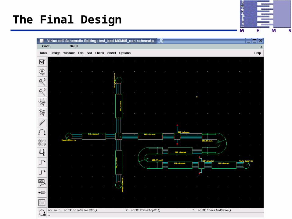
The Final Design
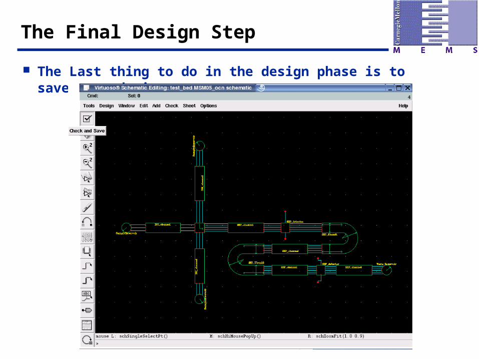
The Final Design Step
The Last thing to do in the design phase is to save your design
Possible errors and warnings
One possible warning that might arise is the occurrence of floating input or output pins
This might be because of simple wiring errors can be corrected by zooming in on the warning points (highlighted yellow by Cadence) on the schematic and checking if the required points are indeed connected
Possible warnings and errors
Check to make sure all the instances are properly oriented with other connections and instances in the system
Incase they are not follow these steps
1. Click on the misorientated (all instances need to look like ones shown in slide 39) instance and delete it
2. Add a new instance and play with the Sideways and Rotate buttons to get the proper orientation of the instance
3. Add the instance back on the schematic and connect it back to the other blocks
4. If you notice convoluted wiring around instances, it is an indication that the instance is not oriented properly with respect to the other blocks
Things to note
Make sure the mobilities and diffusivities denoted by variables mu1,mu0,D1,D0 are set in each instance
This will be crucial to getting a proper output
Related Documents