1 11 Seismic retrofit 11.1 Introduction Seismic retrofit of bridges which do not satisfy the current design requirements is increasingly important worldwide. A large amount of scientific knowledge on the seismic performance of structures has been accumulated in the last three decades. Seismic requirements have been upgraded and a large number of bridges which fail to meet the current level of seismic requirements need retrofit. Seismic retrofit of existing bridges is generally more difficult than design of new bridges because there are various restrictions in the seismic retrofit. Main structural components cannot be changed or replaced in seismic retrofit, which narrows possible options of design and construction. Because bridges are often required to be retrofitted in a short period without suspension of traffic, this imposes difficult restrictions on design criteria and retrofit methods. It should be noted that bridges can be retrofitted only when it is technically, economically and socially feasible. The bridges which fail to meet those requirements have to be replaced with new bridges. Seismic performance levels and goals have to be clearly determined in seismic retrofit. It is always the argument on which level a bridge should be retrofitted. Meeting with the current high seismic performance requirements is generally difficult to the bridges which were designed and built in the early days. Even if the retrofit is feasible, it may be virtually equivalent to reconstruction of substructures in such bridges. In the determination of seismic performance levels and goals, it should be noted that the cost for construction of an access road, retaining wall, dry-up of foundations and treatment of soils or water for preventing pollution is more or less the same with or even higher than the cost for repair itself. It should be also noted that criticism from the public must be very strong if the bridge which is once retrofitted suffers extensive damage in the future earthquake. An important aspect of seismic retrofit is that difficult restrictions and requirements in retrofit design sometimes validate to use new materials and construction methods. Consequently seismic retrofit is a good opportunity for engineers and researchers for challenging to use new and high performance materials and to develop new construction methods. Seismic retrofit follows the standard seismic design and construction procedures for a new bridge. The only difference with design of a new bridge is that actual strength and capacity instead of nominal values should be used in retrofit design. Options of seismic retrofit depend on materials and construction methods available. This chapter introduces retrofitting of bridges with an emphasis on showing various examples of seismic retrofit. 11.2 Retrofit of columns and piers 11.2.1 Introduction Reinforced concrete columns which were designed in accordance with the practice which did not take account of the importance of plastic deformation and ductility capacity are

Welcome message from author
This document is posted to help you gain knowledge. Please leave a comment to let me know what you think about it! Share it to your friends and learn new things together.
Transcript
1
11 Seismic retrofit 11.1 Introduction
Seismic retrofit of bridges which do not satisfy the current design requirements is increasingly important worldwide. A large amount of scientific knowledge on the seismic performance of structures has been accumulated in the last three decades. Seismic requirements have been upgraded and a large number of bridges which fail to meet the current level of seismic requirements need retrofit.
Seismic retrofit of existing bridges is generally more difficult than design of new bridges because there are various restrictions in the seismic retrofit. Main structural components cannot be changed or replaced in seismic retrofit, which narrows possible options of design and construction. Because bridges are often required to be retrofitted in a short period without suspension of traffic, this imposes difficult restrictions on design criteria and retrofit methods. It should be noted that bridges can be retrofitted only when it is technically, economically and socially feasible. The bridges which fail to meet those requirements have to be replaced with new bridges.
Seismic performance levels and goals have to be clearly determined in seismic retrofit. It is always the argument on which level a bridge should be retrofitted. Meeting with the current high seismic performance requirements is generally difficult to the bridges which were designed and built in the early days. Even if the retrofit is feasible, it may be virtually equivalent to reconstruction of substructures in such bridges. In the determination of seismic performance levels and goals, it should be noted that the cost for construction of an access road, retaining wall, dry-up of foundations and treatment of soils or water for preventing pollution is more or less the same with or even higher than the cost for repair itself. It should be also noted that criticism from the public must be very strong if the bridge which is once retrofitted suffers extensive damage in the future earthquake.
An important aspect of seismic retrofit is that difficult restrictions and requirements in retrofit design sometimes validate to use new materials and construction methods. Consequently seismic retrofit is a good opportunity for engineers and researchers for challenging to use new and high performance materials and to develop new construction methods.
Seismic retrofit follows the standard seismic design and construction procedures for a new bridge. The only difference with design of a new bridge is that actual strength and capacity instead of nominal values should be used in retrofit design. Options of seismic retrofit depend on materials and construction methods available.
This chapter introduces retrofitting of bridges with an emphasis on showing various examples of seismic retrofit. 11.2 Retrofit of columns and piers 11.2.1 Introduction
Reinforced concrete columns which were designed in accordance with the practice which did not take account of the importance of plastic deformation and ductility capacity are

2
commonly deficient in flexural ductility, shear strength and flexural strength under strong seismic excitation. Lap splices in critical regions (refer to Fig. 11.1), premature termination of longitudinal reinforcement (Fig. 11.2) and lack of lateral confinement (Fig. 11.3) are the common practice which affects the deficiency.
Fig. 11.1 Failure of a column due to inadequate lap splice (Northridge earthquake)
Fig. 11.2 Premature shear failure of a column with termination of longitudinal bars with
insufficient development length (Kobe earthquake)
(a) (b)
Fig. 11.3 Shear failure of columns; (a) Northridge, USA earthquake and (b) Kobe, Japan earthquake

3
A number of column retrofit techniques have been developed and clarified based on loading tests. Columns retrofit techniques include steel jacketing, composite materials jacketing involving fiberglass, carbon fiver reinforced plastics, aramid fiver reinforced plastics and other fivers, and jacketing with reinforced concrete and precaste concrete. Of these, the most common retrofit technique implemented to date has been steel jacketing and reinforced concrete jacketing, with lesser amount of retrofit involving precast concrete segment jackets and composite materials jackets. Retrofit with emphasis on the four approaches are introduced in the following.
11.2.2 Steel jacketing 11.2.2.1 Steel jacket for circular columns
Providing a jacket around an existing column which has insufficient ductility and strength capacity is effective to prevent premature failure. The jacket is fabricated so that its radius is 12.5 to 25 mm larger than the column radius. After positioned over the areas to be retrofitted and are site-welded up the vertical seams to provide a continuous tube with a small annular gap around the column, the gap is grouted with epoxy resign or a pure cement grout.
The jacket resists not only tension and compression but also shear of the column. Lateral confinement to the core concrete can also be provided by the jacket. Because a jacket cannot sufficiently provide the lateral confinement to a rectangular column if special detailings are not included, the steel jacketing is more appropriate to circular columns than rectangular columns. However restriction exists for hollow circular columns in which confinement from inside cannot be well provided. Furthermore, because columns with much larger radius than buildings are used in bridges, effectiveness of the steel jacket to columns with large radius (over 4 m) is still required to be clarified.
Smooth setting of a steel jacket and availability of structural steel plates restrict a minimum thickness of the jacket. Because a steel plate with a thickness in the rage of 6-12 mm is generally use for the jacket, an amount of steel of a jacket is very large compared to the existing longitudinal and tie bars.
A steel jacket enhances the shear and flexural strength and the ductility capacity of the column. Generally the enhancement of shear and flexural strength of the column increases the moment and shear demand of the foundation. Because redundancy of the moment and shear capacity of a foundation which was designed in the early days is limited, and because retrofit of a foundation is much costly than the retrofit of a column, the increase of the moment and shear demand of the foundation is not most likely preferable.
Consequently, there are essentially two practices in the steel jacketing. First practice is to restrict an amount of the increase of moment and shear demand of the foundation as small as possible. For this purpose, it is recommended to provide a space between the jacket and the footing or cap beam to avoid excessive flexural and shear strength enhancement of the plastic hinge. The gap depends on the radius of the column, but a 50-100 mm gap is generally recommended so that stable plastic hinge can be formed at the plastic hinge.
The other is to allow a certain amount of the increase of moment and shear demand of the foundation. If the foundation has some redundancy on the moment and shear capacity, this is effective to restrict excessive plastic displacement of the column. In particularly, it is appropriate to avoid excessive residual displacement of the column.
The jacket is effective in passive confinement. The level of lateral confinement induced in the concrete by flexible restraint as the concrete attempts to expand laterally in the compression zone depends on the hoop strength and stiffness of the steel jacket. A similar action occurs in resisting the lateral column dilation associated with development of diagonal shear cracks. In both the confinement of flexural hinges or potential shear failures, the steel

4
jacket can be considered equivalent to continuous hoop reinforcement. Fig. 11.4 shows lateral force-displacement hystereses of a retrofitted circular column
(Priestly, Seisble and Calvi1996). Flexural response of the columns is typically limited by the effective ultimate tension strain of the longitudinal reinforcement. This may be taken as 0.75 suε , where suε is the strain at maximum stress.
Steel jacketing has been widely used in California for lap splice retrofit as shown in Fig.
11.5 as the major retrofit technique for bridge columns, with several thousands column thus retrofitted. Extensive experimental studies have been conducted to develop steel jacketing technique (Chai et al 1990). During the 1994 Northridge earthquake, some 50 bridges with steel jacketed columns were subjected to peak ground acceleration of 0.3g or higher. None of these bridges suffered damage to columns requiring subsequent remedial work.
(a) (b)
Fig. 11.5 Steel jacket retrofit of columns; (a) Los Angeles, and (b) San Francisco
D
jt
grout gap1” (25mm)typical
original column
D
jt
grout gap1” (25mm)typical
original column
(a) circular column with circular jacket (b) Lateral force vs. lateral displacement
Fig. 11.4 Lateral force displacement response of columns retrofitted with steel jackets for enhanced ductility (Priestley, Seible and Calvi)

5
Steel jacketing has been also used in Japan for retrofit of premature shear failure resulted from termination of longitudinal reinforcement with inadequate development length. After this problem was first recognized in 1982 Urakawa-oki earthquake, extensive studies were initiated. In particular, a series of experiment in 1987 (Kawashima et al 1990) lead retrofit of nearly 50 columns since 1989 (Akimoto et al 1990). Steel jackets with 9 or 12 mm thick plates were used as shown in Figs. 11.6 and 11.7 depending on the column radius. The columns which were retrofitted in 1989 (Fig. 11.7) were subjected to ground accelerations with nearly 0.8g PGA during the 1995 Kobe earthquake. None of the columns retrofitted suffered damage but the columns which were not retrofitted and were next to the retrofitted columns suffered extensive damage. Since 1995 Kobe earthquake over 40,000 columns and piers were retrofitted in roads and railways in Japan although number of circular columns are much smaller than rectangular columns.
Fig. 11.6 Steel Jacket Retrofit at Fig. 11.7 Steel Jacket Retrofit at Hanshin
Metropolitan Expressway in 1989 Expressway in 1989, which was effective during the 1995 Kobe earthquake
11.2.2.2 Steel jacket for rectangular columns
A rectangular steel jacket is effective for enhancing the shear and moment capacity of a
rectangular column, but it cannot provide sufficient lateral confinement in critical region as the size of the column increases.
Extensive studies have been conducted for retrofit of rectangular columns. For example, Figs. 11.8 and 11.9 show the effect of elliptical jacket, built-up steel channels, and stiffened rectangular jacket on lap splices in critical regions (Chai et al 1990). With an elliptical jacket, the column showed subsequent improved behavior compared to the as-built-column. Bond failure at the lap-splice of the longitudinal reinforcement resulted in the final failure. The elliptical jacket restrained the spalling of covering concrete, and therefore allowed more gradual deterioration of strength. The bolted system of retrofit using built-up steel channels shows stable response up to 6 times yield displacement, after which bond failure at the lap-splice was again the cause for strength deterioration. Stiffened rectangular jacket indicated an earlier and more rapid deterioration of strength.
Based on the studies, rectangular steel jackets on rectangular columns are not generally recommended although they can be expected to be fully effective for shear strength enhancement. An elliptical jacket is recommended to a rectangular column.
On the other hand, because rectangular columns are mostly used and because the enlarging the size of the columns using elliptical jackets is not generally allowed, an extensive study has been conducted in Japan for retrofit of rectangular columns. Based on various attempts, a rectangular jacket which was confined by a stiffened lateral beam at the bottom as shown in Fig. 11.10 was proposed. Stiffness of the lateral beam must satisfy a

6
requirement depending on a ratio of the wider and shorter widths of the section. Generally H-shape beams are used for the lateral beams. Either 9 mm or 12 mm thick steel plates are used for rectangular jacket. Non-Shrinkage mortar or epoxy resin is grouted between the jacket and the column. Generally a 50-100 mm gap is provided between the jacket and the footing for ductility retrofit.
(a) (b)
(c) (d)
Fig. 11.8 Retrofit for Rectangular Columns; (a) Column 1 - ‘As-Built’ (b) Column 2 - Elliptical Retrofit (c) Column 3 - ‘Built-up’ Steel Channels (d) Column 4 - Stiffened Rectangular Jacket
(a) (b)

7
(c) (d)
Fig. 11.9 Hysteretic Response of Rectangular Flexural Columns; (a) Column 1 - ‘As-Built’ (b) Column 2 - Elliptical Retrofit (c) Column 3 - ‘Built-up’ Steel Channels (d) Column 4 - Stiffened Rectangular Jacket
Lateral Beam
Anchor Bolts
Steel Jacket
Small Gap
Existing Longitudinal Bars
Anchor Bolts
50~1
00m
mLateral Beam
Steel Jacket
Fig. 11.10 Rectangular Steel Jacket with Controlled Enhancement of Flexural Capacity
-400
-200
0
200
400
-150 -100 -50 0 50 100 150
-4 -2 0 2 4
Late
ral F
orce
(kN
)
Lateral Displacement (mm)
Drift Ratio (%)
-400
-200
0
200
400
-150 -100 -50 0 50 100 150
-4 -2 0 2 4
Late
ral F
orce
(kN
)
Lateral Displacement (mm)
Drift Ratio (%)
(a) (b)
Fig. 11.11 Effect of Steel Jacket with Controlled Enhancement of Flexural Capacity for Rectangular Piers [Hoshikuma et al 1996, Unjoh et al 1997]; (a) As-Built, (b) Retrofitted
Because enhancement of the flexural capacity of a column is in favor of mitigating the residual displacement after an earthquake, the flexural capacity of the column can be enhanced under the level that does not result in excessive damage in the foundation. For this purpose, the lateral beam welded to the jacket is constraint to the footing by anchor bolts. Level of constrain depends on the redundancy of the moment and shear demand of the foundation. Consequently, radius and number of the anchor bolts are decided depending on the redundancy of the foundation. Because this retrofit allows a certain enhancement of flexural capacity of a column, it is called steel jacket with controlled enhancement of flexural capacity.

8
Fig. 11. 12 Test Models (9m tall and 2.5m x 2.5 m section) for Steel Jacketing with
Controlled Enhancement of Flexural Capacity
-6.0
-4.0
-2.0
0.0
2.0
4.0
6.0
-5 -4 -3 -2 -1 0 1 2 3 4 5
Late
ral F
orce
(MN
)
Drift (%)
-6.0
-4.0
-2.0
0.0
2.0
4.0
6.0
-5 -4 -3 -2 -1 0 1 2 3 4 5
Late
ral F
orce
(MN
)
Drift (%) (a) (b)
Fig. 11.13 Effect of steel jacket with controlled enhancement of flexural capacity for full-scale square column (Hoshikuma et al ????)
Fig. 11.11 shows a verification test on the steel jacket with controlled enhancement of
flexural capacity using a 3.01 m high rectangular column with a section of 600x600 mm (Hoshikuma et al. 1996, Unjoh et al. 1997). Flexural capacity and displacement ductility capacity of the as-built column were enhanced by a factor of 1.39 and 1.4, respectively, by the retrofit. A verification test was also conducted to a full scale square column (9 m tall and 2.5 m wide) as shown in Fig. 11.12. Fig. 11.13 shows the effectiveness of the steel jacketing wit controlled enhancement of flexural capacity.
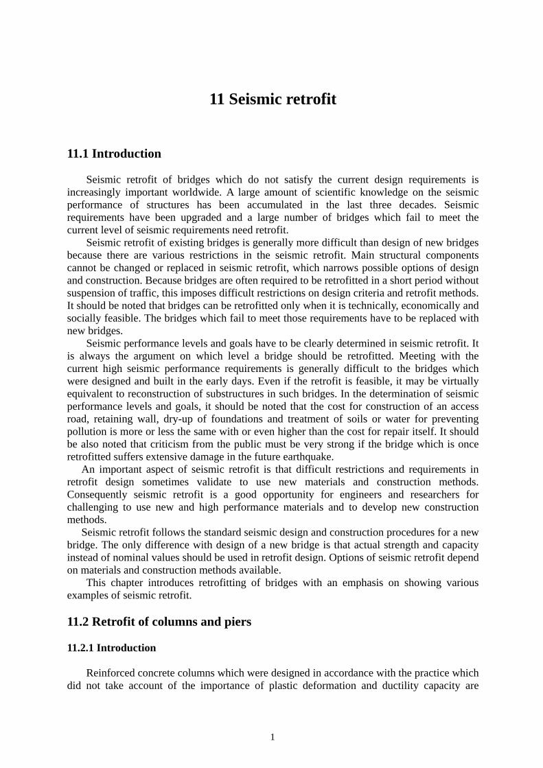
Fig. 11.14 shows an example of retrofit by steel jacket with controlled enhancement of flexural capacity for a 7.5 m tall column. The column had the insufficient premature termination of longitudinal bars at 4.7 m from the bottom. Consequently prmature shear failure was anticipated. Furthermore because the flexural capacity was insufficient, an excessive residual displacement was anticipated. Nine mm thick steel plates and H-shape beams with a section of 300x300x10 mm were used for the jacket and the lateral beam, respectively. Thirty two 35 mm radius anchor bolts were used to enhance the flexural capacity (Japan Road Association 1997).
9
Fig. 11.14 Retrofitted Section and anchor bolts
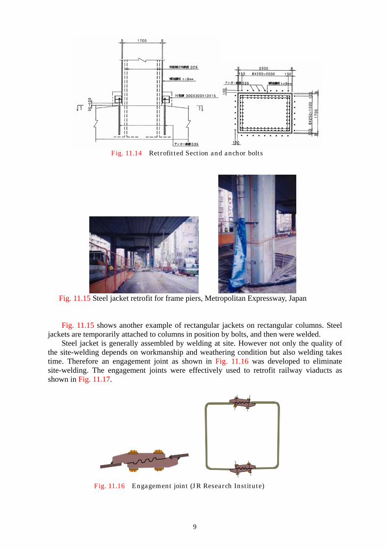
Fig. 11.15 Steel jacket retrofit for frame piers, Metropolitan Expressway, Japan Fig. 11.15 shows another example of rectangular jackets on rectangular columns. Steel
jackets are temporarily attached to columns in position by bolts, and then were welded. Steel jacket is generally assembled by welding at site. However not only the quality of
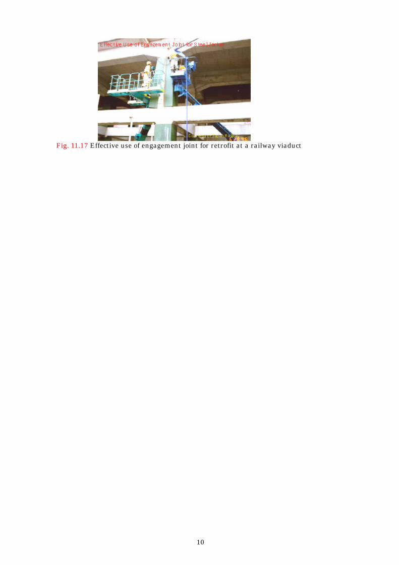
the site-welding depends on workmanship and weathering condition but also welding takes time. Therefore an engagement joint as shown in Fig. 11.16 was developed to eliminate site-welding. The engagement joints were effectively used to retrofit railway viaducts as shown in Fig. 11.17.
Fig. 11.16 Engagement joint (JR Research Institute)
10
Effective Use of Engagement Joint for Steel Jacket
Courtesy of Japan Railway Fig. 11.17 Effective use of engagement joint for retrofit at a railway viaduct

11
(a) (b) (c)
Fig. 11.18 Steel jacket repair and retrofit for shear; (a) shear failure after loaded, (b)
repaired by steel jacketing, and (c) flexural failure of retrofitted column (after steel jacket was removed)
-600
-400
-200
0
200
400
600
-300 -200 -100 0 100 200 300
Late
ral F
orce
(tf)
Lateral Displacement (mm)
-600
-400
-200
0
200
400
600
-300 -200 -100 0 100 200 300
Late
ral F
orce
(tf)
Lateral Displacement (mm) (a) (b)
Fig. 11.19 Effect of steel jacket for shear enhancement; (a) as-built, and (b) steel jacketing Steel jackets are used for not only retrofit but also repair of columns which suffer
damage. For example, Fig. 11.18 shows a test conducted to verify the effectiveness of a rectangular steel jacket to repair a rectangular column which fails in shear. The column was first loaded to fail in shear. After shear cracks were grouted with epoxy resin, the column was repaired by a rectangular jacket. The repaired column was loaded again to fail in flexure. Significant enhancement of ductility and strength capacity was achieved by the steel jacketing as shown in Fig. 11.19.
10.2.3 Reinforced concrete jacket and shear wall 10.2.3.1 Reinforce concrete jacket
In a reinforced concrete jacketing new reinforced concrete section is constructed around the existing columns and piers to enhance the strength and ductility capacities. The new section and the existing section have to be well connected together. For this purpose, anchor bolts are generally inserted and grouted with a cement mortar after chipping out of the covering concrete and drilling holes at the section of connection. Because the new section is
12
at least 200 mm thick and most likely 300 mm, the flexural capacity is generally much enhanced. As a consequence, redundancy of the foundation due to an increase of flexural demand has to be well clarified in the reinforced concrete jacketing.
Reinforced concrete jacketing is frequently used based on two reasons. First, it is generally cheaper than other retrofit measures. However because direct cost for retrofit is only a part of the total cost, selection of an appropriate retrofit method has to decided based on various other considerations. Second, the reinforced concrete jacketing is favorable in retrofit of columns in water. Based on this reason, the reinforced concrete jacket is much widely used than the steel jacketing for columns in river and sea.
Similar to the steel jacketing, there are essentially two strategies in flexural enhancement depending on redundancy on the demand of a foundation. First is to provide a gap between the jacket and the footing. The other is to anchor new rebars into the footing.
Same with the steel jacketing, reinforced concrete jacketing is effective for circular columns but not for rectangular columns as the cross section increases. Consequently required are ties or anchors which are provided crossing the section in the weak (mostly longitudinal) direction. Because cross ties are more important in wall piers, retrofit by reinforced concrete jacket is described below for wall piers. The same methods can be used to square columns.
Wall piers are widely used in various regions worldwide. Wall piers which were designed and constructed in the early days were generally insufficiently reinforced. Volumetric tie reinforcement ratio was sometimes less than 0.1%. As a result, they have essentially insufficient flexural and shear strengths and ductility capacity.
(a) (b)
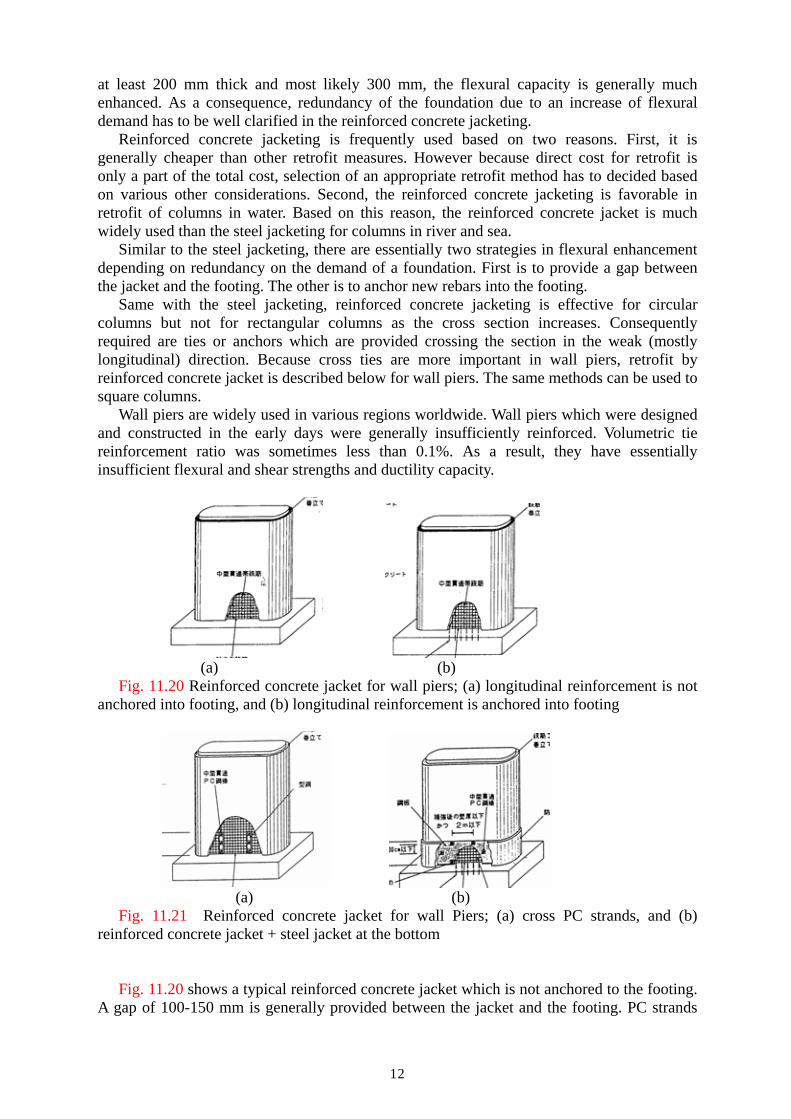
Fig. 11.20 Reinforced concrete jacket for wall piers; (a) longitudinal reinforcement is not anchored into footing, and (b) longitudinal reinforcement is anchored into footing
(a) (b) Fig. 11.21 Reinforced concrete jacket for wall Piers; (a) cross PC strands, and (b)
reinforced concrete jacket + steel jacket at the bottom Fig. 11.20 shows a typical reinforced concrete jacket which is not anchored to the footing.
A gap of 100-150 mm is generally provided between the jacket and the footing. PC strands

13
are provided and grouted in drilled holes to enhance the lateral confinement. PC strands are generally provided at every 300 mm and 1m in the vertical and transverse directions, respectively. Prestress is not generally provided in the PC strands because passive confinement is expected. Based on a loading test, a prestressing force in PC strand makes the plastic hinge of the pier shorter resulting in smaller ductility capacity.
Drilling holes crossing a pier is always difficult because drilling most likely cuts the existing reinforcements. Although a razor sensor, sound echo sensors and other devices are used, it is always troublesome to drill holes crossing a pier. Consequently technologies which eliminate or use rods with smaller radius are being developed as will be described later. Cutting of concrete by high water pressure was developed to split a pier into several segments so that cross ties can be easily set.
Fig. 11.21 shows a reinforced concrete jacket which is anchored to the footing. Because the pier responds almost elastically, this can be used only when the foundation has sufficient flexural and shear capacities. In addition to a reinforced concrete jacket, a 1-2 m high steel jacket is sometimes provided at the base for protection.
Fig. 11.22 Reinforced concrete jacket with steel jacket at the plastic hinge for a 5.3 m tall
wall Pier Fig. 11.22 shows an example of the reinforced concrete jacket with a steel jacket at the
plastic hinge. It is a 5.3 m high wall pier with a 8.5 m and 2.5 m section in the transverse and longitudinal directions, respectively. New longitudinal rebars with a radius of 32 mm were provided at an interval of 125 mm along the existing pier. A half of the longitudinal rebars was anchored in the footing, and the rest was not anchored. New ties with a radius of 22 mm were placed at every 100 mm interval. Six mm thick and 2.1 m high steel jacket was set surrounding the new reinforced concrete jacket. Forty nine PC strands with a radius of 32 mm were provided crossing the section at 300 mm and 1000 mm interval in the vertical and transverse directions, respectively.
Aramid fiber reinforced plastics rods which were described in 10.2.3 b) can be used as cross bars in the retrofit of wall piers. Aramid fiber reinforced plastics rods have several advantages as cross bas compared to normal steel bars or PC strands. First, the aramid fiber reinforced plastics rods have lower elastic modulus than PC strands. Consequently, it is easier to introduce a prestressing force with lesser deterioration of the prestressing force due to

14
creep. Second, because bond strength between the aramid fiber reinforced plastics rods and concrete section is higher than steel bars or PC strands, a large anchor device is not required. Therefore, anchoring of aramid fiber reinforced plastics bars with reinforced concrete section is much easier than PC strands. Third, lateral confinement of the existing RC section can be achieved using the aramid fiber reinforced plastics rods with smaller radius. This makes the drilling easier and faster than the rebars or PC strands.
Effectiveness of aramid fiber reinforced plastics rods as cross bars was clarified based on a series of cyclic loading test as shown in Fig. 11.23 (Tamaoki et al 1996). Seven 2 m tall wall piers with a section of 2.5 m and 0.5 m were retrofitted by 2.3 mm thick steel jacket at the entire height. They were further retrofitted by 100 mm thick reinforced concrete jacket at the plastic hinge zone to enhance the flexural strength of the piers. Because the prototype piers had insufficient flexure strength (refer to Fig. 11.23 (a)), enhancement of the flexural strength and the ductility capacity was required. Effect of steel rebars, PC strands and aramid fiber reinforced plastics rods (Refer to Fig. 11.23 (b)) as cross bars were clarified. Aramid fiber reinforced plastics rods with a radius of 6 mm were provided at 500 mm and 250 mm interval in the lateral and vertical directions, respectively. Effect of introducing prestressing force in the aramid fiber reinforced plastics rods was also studied.
(a) (b)
Fig. 11.23 Cyclic loading test on the retrofit of wall pier by steel jacket covered by reinforced concrete jacket with cross aramid fiber reinforced plastics rods; (a) as built pier, and (b) pier retrofitted using cross aramid fiber reinforced plastics rods
Table 11.1 Effectiveness of cross aramid rods for retrofit of wall piers based on a bcyclic loading test
Lateral Confinement in the Weak (Longitudinal) Direction Maximum Restoring Force (kN)
Ductility Factor
As-built 609 5.1 Steel jacket at the entire height covered by RC jacket at the plastic hinge zone (standard model)
616 8.1
Standard model + cross bars (steel bars with a radius of 16 mm( at the plastic hinge zone
626 11.8
Standard model + cross bars (PC bars with a radius of 7.1 mm) at the plastic hinge zone
603 12.0
Standard model + cross bars (PC bars with a radius of 11 mm) at the plastic hinge zone
614 12.6
Standard model + cross bars (aramid fiber reinforced plastics bars with a radius of 6 mm without prestress) at the plastic hinge zone
606 14.0
Standard model + cross bars (aramid fiber reinforced plastics bars with a radius of 6 mm with prestress) at the plastic hinge zone
702 12.9

15
Table 11.1 summarizes the effect of retrofit in terms of the maximum restoring force and the ductility capacity. It is obvious that the ductility capacity of the pier without lateral confinement in the weak direction is insufficient. The aramid fiber reinforced plastics rods are effective to enhance the ductility capacity as well as the flexural strength by well confining the piers in the weak direction.
The cross aramid fiber reinforced plastics rods were implemented to several bridges. For example, Fig. 11.24 shows retrofit of wall piers based on the experimental clarification described above. After steel jacket was provided (refer to Fig. 11.24 (a)), aramid fiber reinforced plastics rods were set in drilled holes in the weak direction (refer to Fig. 11.24 (b)). After prestressing force was introduced in the aramid fiber reinforced plastics, a reinforced concrete jacket was further provided at the plastic hinge zone (refer to Fig. 11.24 (c)).
(a)
(b) (c)
Fig. 11.24 Retrofit using cross aramid fiber reinforced plastics rods to wall piers; steel jacketing, (b) set of cross aramid fiber reinforced plastics rods, and (c) after retrofitted
10.2.3.3 Infilled shear walls
Infilled shear walls are frequently used to retrofit framed piers. Because infilled wall provides high shear and flexural capacity in the direction parallel to the wall (most likely in the transverse direction), it increases flexural and shear demand of the foundation. Therefore seismic performance of the foundation has to be carefully evaluated.
Frame piers which were designed in the early days are often vulnerable for shear because shear capacity of beams and columns as well as their joints is insufficient. Similar to wall piers, they are very lightly reinforced and lateral confinement is insufficient. Basic strategy for retrofit of frame piers is to retrofit all columns, lateral beams and joints. Another stragegy is to build a new infilled shear wall.
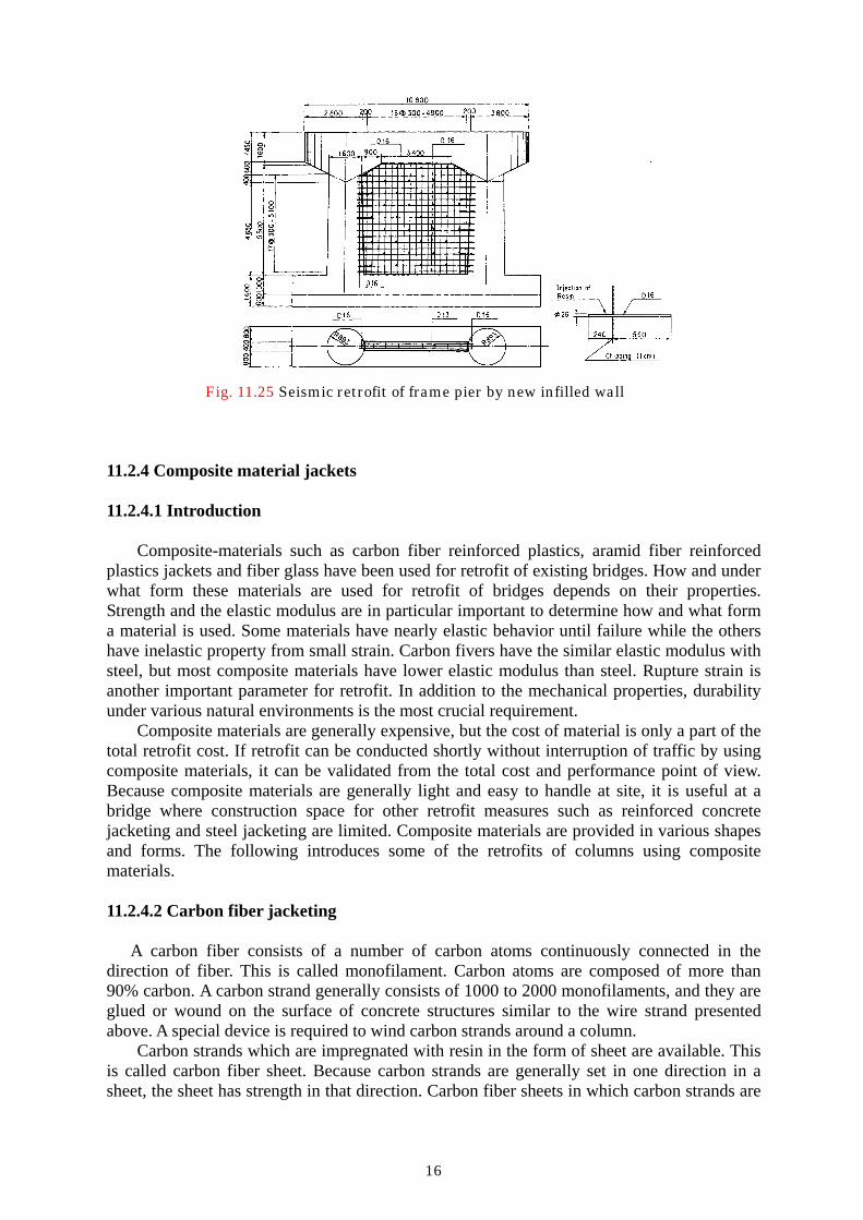
Fig. 11.25 shows an example of an infilled shear wall for a 8.7 m tall reinforced concrete frame pier. The shear wall was 400mm. thick The covering concrete of the existing substructures was chipped-out, and holes with a radius of 26mm were drilled. Anchor bars with a radius of 16mm were set and grouted with epoxy resin at every 300 mm interval.
16
Fig. 11.25 Seismic retrofit of frame pier by new infilled wall
11.2.4 Composite material jackets 11.2.4.1 Introduction
Composite-materials such as carbon fiber reinforced plastics, aramid fiber reinforced
plastics jackets and fiber glass have been used for retrofit of existing bridges. How and under what form these materials are used for retrofit of bridges depends on their properties. Strength and the elastic modulus are in particular important to determine how and what form a material is used. Some materials have nearly elastic behavior until failure while the others have inelastic property from small strain. Carbon fivers have the similar elastic modulus with steel, but most composite materials have lower elastic modulus than steel. Rupture strain is another important parameter for retrofit. In addition to the mechanical properties, durability under various natural environments is the most crucial requirement.
Composite materials are generally expensive, but the cost of material is only a part of the total retrofit cost. If retrofit can be conducted shortly without interruption of traffic by using composite materials, it can be validated from the total cost and performance point of view. Because composite materials are generally light and easy to handle at site, it is useful at a bridge where construction space for other retrofit measures such as reinforced concrete jacketing and steel jacketing are limited. Composite materials are provided in various shapes and forms. The following introduces some of the retrofits of columns using composite materials. 11.2.4.2 Carbon fiber jacketing
A carbon fiber consists of a number of carbon atoms continuously connected in the direction of fiber. This is called monofilament. Carbon atoms are composed of more than 90% carbon. A carbon strand generally consists of 1000 to 2000 monofilaments, and they are glued or wound on the surface of concrete structures similar to the wire strand presented above. A special device is required to wind carbon strands around a column.
Carbon strands which are impregnated with resin in the form of sheet are available. This is called carbon fiber sheet. Because carbon strands are generally set in one direction in a sheet, the sheet has strength in that direction. Carbon fiber sheets in which carbon strands are

17
impregnated with resin in two directions are available. Because carbon fiber sheet can be easily cut by knife in any size and shape, it is easy to handle and glue it on the surface of a concrete structure as shown in Fig. 11.26. Consequently, carbon fiber sheets have been most extensively used for seismic retrofit of columns among several forms of carbon fiber reinforced plastics.
タ
トル
文
W i f fi C b Fib
タ
i i t d th fi t h t
(a) (b) (c) Fig. 11.26 Wrapping of carbon fiber sheet; (a) pasting glue, (b) wrapping the first layer,
and (c) bonding on the first layer The elastic modulus and strength of standard carbon fiber are nearly the same with and
about 10 times larger, respectively, than those of reinforcing bars. Carbon fibers have essentially linear stress-strain characteristics up to failure. Rupture strain is about 2%. As a consequence, when the core concrete is laterally confined by carbon fibers, residual plastic strains do not remain in the carbon fiber jacket, without reducing its effectiveness until rupture for the confinement for the next cycle of response. Therefore, carbon fiber is more effective than steel rebars in the flexural retrofit and to resist shear in the shear retrofit. There are special carbon fibers with higher elastic modulus and strength. Because the elastic modulus of carbon fiber is the largest among the composite materials currently available, it is effective for lateral confinement of a column. Carbon fiber was first introduced to repair damage of concrete structures, and it has been extended to seismic retrofit of columns since 1980s.
Axia
l Stre
ss R
atio
(fc/
fco)
Axial Strain
ρS= 1.24%
ρS= 0.62%
ρS= 0.41%
ρS= 0
0.0
0.5
1.0
1.5
2.0
0 0.01 0.02
EmpiricalExperimental
Axia
l Stre
ss R
atio
(fc/
fco)
Axial Strain
ρS= 1.24%
ρS= 0
ρS= 0.62%
ρS= 0.41%
0.0
0.5
1.0
1.5
2.0
2.5
3.0
0 0.01 0.02 0.03
EmpiricalExperimental
(a) (b) Fig. 11.27 Stress vs. strain of hysteresis of circular concrete confined by ties and carbon
fiber sheets (Kawashima et al 2000)

18
Because a standard carbon fiber sheet has nearly 10 times strength of tie bars, mechanism of the lateral confinement is different with that by tie bars. The lateral confinement provided by ties does not increase after yield of ties, but it builds up nearly ten times the yield strength of ties in the confinement by carbon fiber. As a consequence, if the concrete is confined by sufficient amount of carbon fiber, concrete stress continues to increase with limited stiffness deterioration as concrete strain increases. The lateral confinement of existing columns is developed by both existing ties and carbon fiber. Several empirical confinement models which represent the lateral confinement for arbitrary combinations of ties and carbon fiber are available. For example, Fig. 11.27 shows a stress vs. strain relation of concrete confined by ties and carbon fiber sheets for volumetric carbon fiber sheet ratio of 0.056% and 0.111%. Sudden deterioration of stress occurs when carbon fiber sheet ruptures.
-400
-200
0
200
400
-100 -50 0 50 100
-4 -2 0 2 4
Late
ral F
orce
(kN
)
Lateral Displacement (mm)
Drift Ratio (%)
-400
-200
0
200
400
-100 -50 0 50 100
-4 -2 0 2 4
Late
ral F
orce
(kN
)
Lateral Displacement (mm)
Drift Ratio (%)
(a) (b) Fig. 11.28 Effect of carbon fiber sheet jacketing for a 2.1 m tall circular column (Hoshikuma et al. 1996, Unjoh et al. 1997); (a) as-built, (b) retrofitted -
-100
-50
0
50
100
-100 -50 0 50 100
-4 -2 0 2 4
Late
ral F
orce
(kN
)
Lateral Displacement (mm)
Drift Ratio (%)
-100
-50
0
50
100
-100 -50 0 50 100
-4 -2 0 2 4
Late
ral F
orce
(kN
)
Lateral Displacement (mm)
Drift Ratio (%)
Fig. 11.29 Effect of carbon fiber sheet jacketing for piers in Sakawa-gawa bridge [Ogata et al. 1999, Osada et al. 1999]; (a) as-built, and (b) retrofitted
Fig. 11.28 shows a cyclic loading test on carbon fiber sheet jacket for 2.1m high circular columns with a radius of 700 mm (Unjoh et al. 1997). The carbon fiber sheet was wrapped in two ways; lateral direction alone and both lateral and vertical directions. The carbon fiber sheets wrapped along column height were used to enhance the flexural strength. They were anchored at the upper surface of the footing by steel plates. The carbon fiber sheet wrapped in the lateral direction alone and the lateral + vertical directions enhanced the displacement ductility capacity by a factor of 200% and 300%, respectively.

19
One of the most extensive seismic retrofits of highway bridges using the carbon fiber sheet was implemented at the Sakawa-gawa Bridge, Japan. The bridge consisted of a 5-span continuous steel girder supported by five 42-65 m high hollow reinforced concrete piers. Before the retrofit, a series of cyclic loading tests was conducted to verify the effectiveness (Ogata et al. 1997, Osada et al. 1999). Fig. 11.29 shows the effect of retrofit. Stable flexural capacity range increases from 3% drift (as-built) to over 5% drift (retrofitted). The seismic retrofit by carbon fiber sheet was implemented as shown in Fig. 11.30. Right column was under wrapping while surface treatment was completed at the left columns.
(a) (b)
Fig. 11.30 Carbon fiber sheet jacketing of hollow reinforced concrete columns, Sakawa-gawa bridge, tomei expressway [Ogata et al. 1999, Osada et al. 1999]; (a) retrofitted east- and west-bound bridge, and (b) wrapping of carbon fiber sheets
11.2.4.3 Aramid fiber reinforced plastics jacketing
Aramid fiber reinforced plastics jacketing has benefit similar to the carbon fiber
jacketing. It is light and easy to wrap without heavy machines. Elastic modulus is generally in the range of (0.8-1.2)x105 MPa which is smaller than that of the carbon fiber. Nominal strength and rupture stain are generally in the range of 2.1-2.4 GPa and 1.8-3%, respectively.
Aramid fiber is essentially available in four forms; 1) braided tape, 2) unidirectional tape, 3) sheet and 4) rods. Braided tape is typically 20 mm wide, and it consists of aramid fibers woven in a braid form. Unilateral tape and sheet are fabric woven in a tape form with typically 75 mm wide and sheet, respectively, and they consist of aramid fiber in the axial direction and glass fiber in the transverse direction. Strength of the aramid fiber depends on the quantity of fiber per cross section. Tensile strength of a braided tape and unidirectional tape with 307,200 deniers (1 denier=1 g/9,000 m) and 34.5 mm2 which are impregnated with epoxy resin is 54.7 kN and 36.0 kN, respectively.
Among the above four forms, aramid fiber sheet and aramid fiber rods are well used for seismic retrofit of existing columns and piers. Aramid fiber sheets are used for aramid fiber sheet jacket. Aramid fiber rods are used to confine a pier as cross ties, and to retrofit a footing by providing prestressing force. Examples of the retrofit will be described in the later section.
Effectiveness of aramid jacketing has been clarified based on cyclic loading tests. For

20
example, 625 mm high square columns with a width of 250 mm, which were designed to fail in shear, were retrofitted by aramid braided tape, unidirectional tape and sheet as shown in Fig. 11.31. Smoothing of square section at corners was not conducted. Braided tape and directional tape were helically placed at a 100mm interval. A sheet was cut into 160 mm wide strip, and 4 to 5 sheets were superposed to have the same total fiber quantity with braided tape and unidirectional tape. As shown in Fig. 11.32, as-built column failed in shear, while retrofitted columns failed in flexure. Aramid fiber did not rupture until final loading except the column retrofitted by sheets where sheet ruptured at a corner at a drift of 20/625.
(a) (b)
Fig. 11.31 Retrofit by aramid fiber reinforced plastics; (a) brained tape and unilateral tape, and (b) sheet
-150
-100
-50
0
50
100
150
-30 -20 -10 0 10 20 30
Late
ral F
orce
(kN
)
Displacement (mm)
-150
-100
-50
0
50
100
150
-30 -20 -10 0 10 20 30
Late
ral F
orce
(kN
)
Displacement (mm) (a) (b)
-150
-100
-50
0
50
100
150
-30 -20 -10 0 10 20 30
Late
ral F
orce
(kN
)
Displacement (mm)
-150
-100
-50
0
50
100
150
-30 -20 -10 0 10 20 30
Late
ral F
orce
(kN
)
Displacement (mm) (c) (d)
Fig. 11.32 Effect of retrofit by aramid fiber; (a) no reinforcement, (b) braided tape, (c) UD tape, and (d) sheet
Aramid fiber jackets have been implemented at the sites where steel jackets and
reinforced concrete jackets cannot be used because of space limitation. Because aramid fiber sheets are more flexible than carbon fiber sheets, aramid fiber jacket are superior to retrofit
21
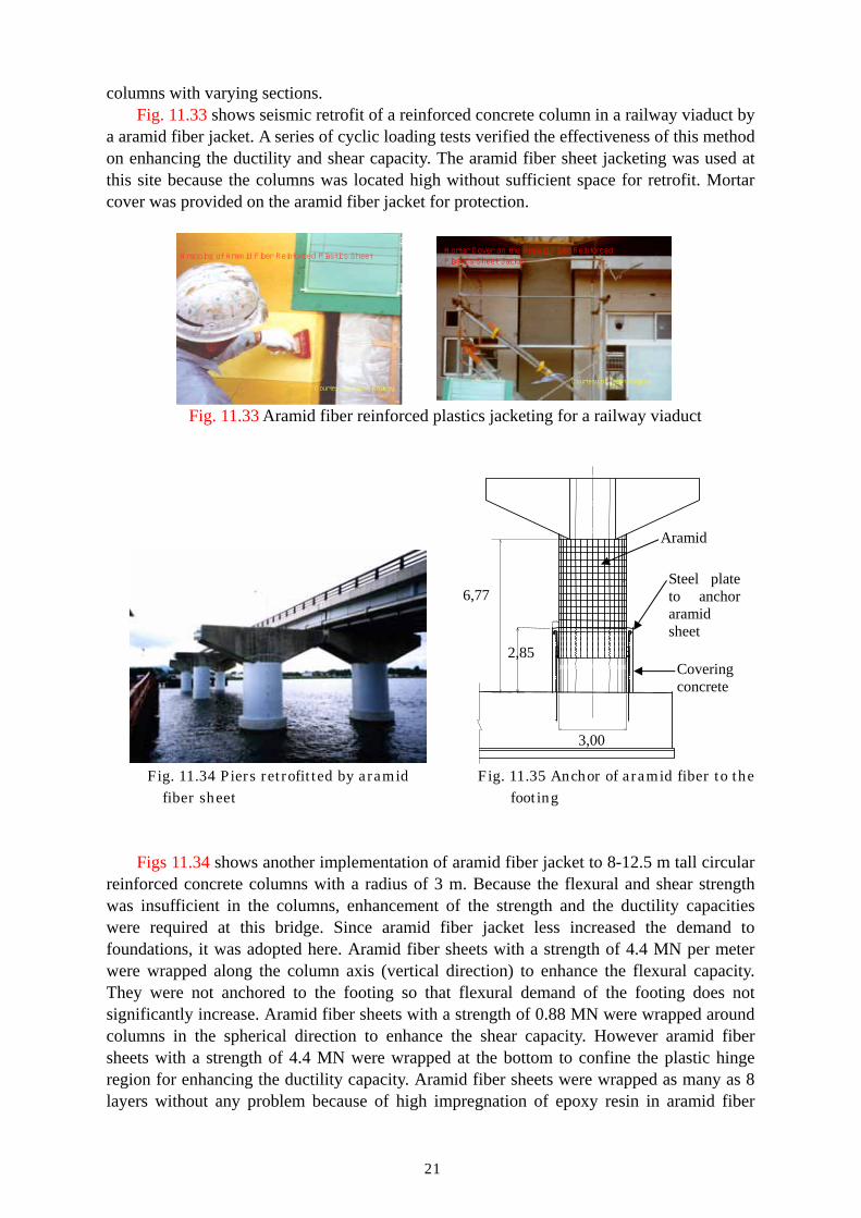
columns with varying sections. Fig. 11.33 shows seismic retrofit of a reinforced concrete column in a railway viaduct by
a aramid fiber jacket. A series of cyclic loading tests verified the effectiveness of this method on enhancing the ductility and shear capacity. The aramid fiber sheet jacketing was used at this site because the columns was located high without sufficient space for retrofit. Mortar cover was provided on the aramid fiber jacket for protection.
Wrapping of Aramid Fiber Reinforced Plastics Sheet
Courtesy of Japan Railway
Mortar Cover on the Aramid Fiber Reinforced Plastics Sheet Jacket
Courtesy of Japan Railway
Fig. 11.33 Aramid fiber reinforced plastics jacketing for a railway viaduct
Fig. 11.34 Piers retrofitted by aramid Fig. 11.35 Anchor of aramid fiber to the
fiber sheet footing Figs 11.34 shows another implementation of aramid fiber jacket to 8-12.5 m tall circular
reinforced concrete columns with a radius of 3 m. Because the flexural and shear strength was insufficient in the columns, enhancement of the strength and the ductility capacities were required at this bridge. Since aramid fiber jacket less increased the demand to foundations, it was adopted here. Aramid fiber sheets with a strength of 4.4 MN per meter were wrapped along the column axis (vertical direction) to enhance the flexural capacity. They were not anchored to the footing so that flexural demand of the footing does not significantly increase. Aramid fiber sheets with a strength of 0.88 MN were wrapped around columns in the spherical direction to enhance the shear capacity. However aramid fiber sheets with a strength of 4.4 MN were wrapped at the bottom to confine the plastic hinge region for enhancing the ductility capacity. Aramid fiber sheets were wrapped as many as 8 layers without any problem because of high impregnation of epoxy resin in aramid fiber
6,77
2,85
3,00
Aramid
Steel plate to anchor aramid sheet
Covering concrete

22
sheets. Because the flexural capacity of a pier and footing system was still insufficient in the
above retrofit at some tall piers, the vertical aramid fiber sheets were anchored to the footing as shown in Fig. 11.35. Steel jacket was provided at the plastic hinge region, and the vertical aramid fiber sheets were bonded to the steel jacket. Detailings of the bond between the steel jacket and the aramid fiber sheets were clarified based on a cyclic loading test.
In addition to the aramid fiber sheets, aramid fiber rods are effective for retrofit of foundations and piers. This will be described later.
11.2.4.4 Glass fiber reinforced plastics jacket
Glass fiber is used for seismic retrofit of columns. Fig. 11.36 shows a rectangular glass
fiber-epoxy jacket placed to enhance shear strength of a short rectangular column (Priestley, Seible and Calvi, 1996). Although it was not expected that the jacket would provide significant enhancement to ductility, it is seen in Fig. 11.36 (b) that the column sustained displacement ductility up to 8, corresponding to drift angle of 4% before jacket failure.
Fig. 11.37 shows another implementation of glass fiber to a railway bridge column. Glass fiber with resin mixture was blasted by a spray gun. Steel cross-mesh was used together with the glass fiber to enhance the strength and ductility of the columns. From a cyclic loading test, it was confirmed that the glass fiber and steel cross-mesh jacket enhanced the ductility capacity.
(a) (b) Fig. 11.36 Rectangular column with glass fiber-epoxy rectangular jacket. (a) failure by jacket fracture; (b) lateral force-displacement response (Priestley, Seible and Calvi 1996)
Fiber Reinforced Plastic Jacket
Japan Railway
Blast of Glass Fiber + Resin
Courtesy of Japan Railway
Fig. 11.37 Glass fiber jacketing (Japan Railway)
23
11. 2.5 Precast concrete segment jacket
Because steel jacket is vulnerable to corrosion, it is not generally used for retrofit of columns under water in river, lake and sea. As described in 11.2.3, reinforced concrete jacket are used for retrofit of columns in water, however it generally takes longer construction period. Setting a new reinforced concrete jacket requires to dry up the top of footing and piers. Therefore a reinforce concrete jacketing is costly.
As a consequence a jacketing method which uses precast concrete segments is now increasingly used for columns in water. There are at least three reasons for the wide acceptance of the precast concrete segment jacketing. First is the technical development which enables to set precast concrete segments without drying up a foundation under water. Second is the faster construction than the standard reinforced concrete jacketing. Setting of prefabricated concrete segments contributes to significantly reduce the construction period. Special joints for connection of segments are sometimes used to further reduce construction period. Third is the cost saving. Because size of the columns is generally more or less the same at a bridge, fabrication of segments in a factory and setting them at the site save the cost compared to the reinforced concrete jacketing. In other word, the precast concrete segment is not competent at the bridges which are supported by irregular columns with different sections.
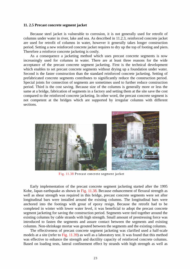
Fig. 11.38 Precast concrete segment jacket
Early implementation of the precast concrete segment jacketing started after the 1995
Kobe, Japan earthquake as shown in Fig. 11.38. Because enhancement of flexural strength as well as shear strength was required in this bridge, precast concrete segments were set after longitudinal bars were installed around the existing columns. The longitudinal bars were anchored into the footings with grout of epoxy resign. Because the retrofit had to be completed in winter with lower water level, it was beneficial to adopt the precast concrete segment jacketing for saving the construction period. Segments were tied together around the existing columns by cable strands with high strength. Small amount of prestressing force was introduced to fasten the segments and assure contact between the segments and existing columns. Non-shrinkage mortar was grouted between the segments and the existing columns.
The effectiveness of precast concrete segment jacketing was clarified used a half-scale models at a site (refer to Fig. 11.39) as well as a laboratory test. It was found that this method was effective to enhance the strength and ductility capacity of reinforced concrete columns. Based on loading tests, lateral confinement effect by strands with high strength as well as

24
existing ties was investigated. Fig. 11.40 shows another example of seismic retrofit of rectangular columns.
Fig. 11.39 In-site loading test on the effectiveness of PC segment jacketing
(a) before retrofit (b) after retrofitted
Fig. 11.40 Columns retrofitted by PC segment jacket; (a) as-built and (b) after retrofitted Various new technologies have been developed since the early implementation of the
precaast concrete segment jackets. There are several directions of technical development. The first is the anchor of segment jackets to the footing without drying up of the foundation. Because dry up of the foundations is costly, it is always the problem in the implementation of seismic retrofit of columns under water. Limiting the construction only at the season with low water level makes the total management difficult. Therefore it is required to have a method which enables to retrofit existing columns without dry up. The second is the extension of this method to wall piers. Because the lateral confinement is insufficient in a wall pier as the width increases, cross ties are necessary to provide the lateral confinement. However drilling holes in a pier to set cross ties is likely to cut the existing longitudinal bars.
A new precast concrete segment jacketing was therefore developed and is now increasingly used. This is featured of several points. The first is the use of vinyl-ester epoxy resin to anchor the anchor bolts in the footing after holes are drilled. Because the resin stably anchors bolts in the footing even under water, dry up of the foundations is not required. After drilled and anchored by divers, precast concrete segments can be set and slide down. The second is to provide lateral confinement by anchor bolts with extended radius at bottom as show in Fig. 11.41. The anchor bolts, which mechanically extend radius at their bottom after they are set in drilled holes extended to core concrete, confine the precast concrete segments.

25
Therefore drilling cross-holes to set cross ties is not required. This avoids the risk of cutting longitudinal bars during the drilling stage and significantly saves the construction period. The third is to connect precast concrete segments together by mechanical joints as shown in Fig. 11.42. After temporarily connected by working joints, mechanical joints are set from the top. This significantly improves the construction efficiency.
(a) (b) Fig. 11.41 PC segment jacket which does not require dry-up of foundations; (a) retrofit
using standard reinforced concrete jacket and cross bars, and (b) retrofit using precast concrete segments with anchors with extended diameter at bottom
Fig. 11.42 Mechanical joint of precast concrete segment jacket
(a) (b) (c) Fig. 11.43 Loading test on the retrofit of hollow rectangular column; (a) section, (b) as
built and (c) retrofitted Several series of tests were conducted to confirm the performance of this retrofit method
For example, Fig. 11.43 shows a loading test to show the effectiveness of this method on a hollow rectangular column. Because longitudinal reinforcements were terminated at mid-heights with insufficient development length (refer to Fig. 11.43 (b)), the premature shear failure occurred in the as-built column. The column was retrofitted by precast concrete
Precast concrete
Anchor bars with extended diameter at
Injection of disaggregate
PC Cross
Reinforced concrete
Mechanical
プレキャストパネル
プレキャストパネル
Precast Temporal joints for construction
Mechanical
26
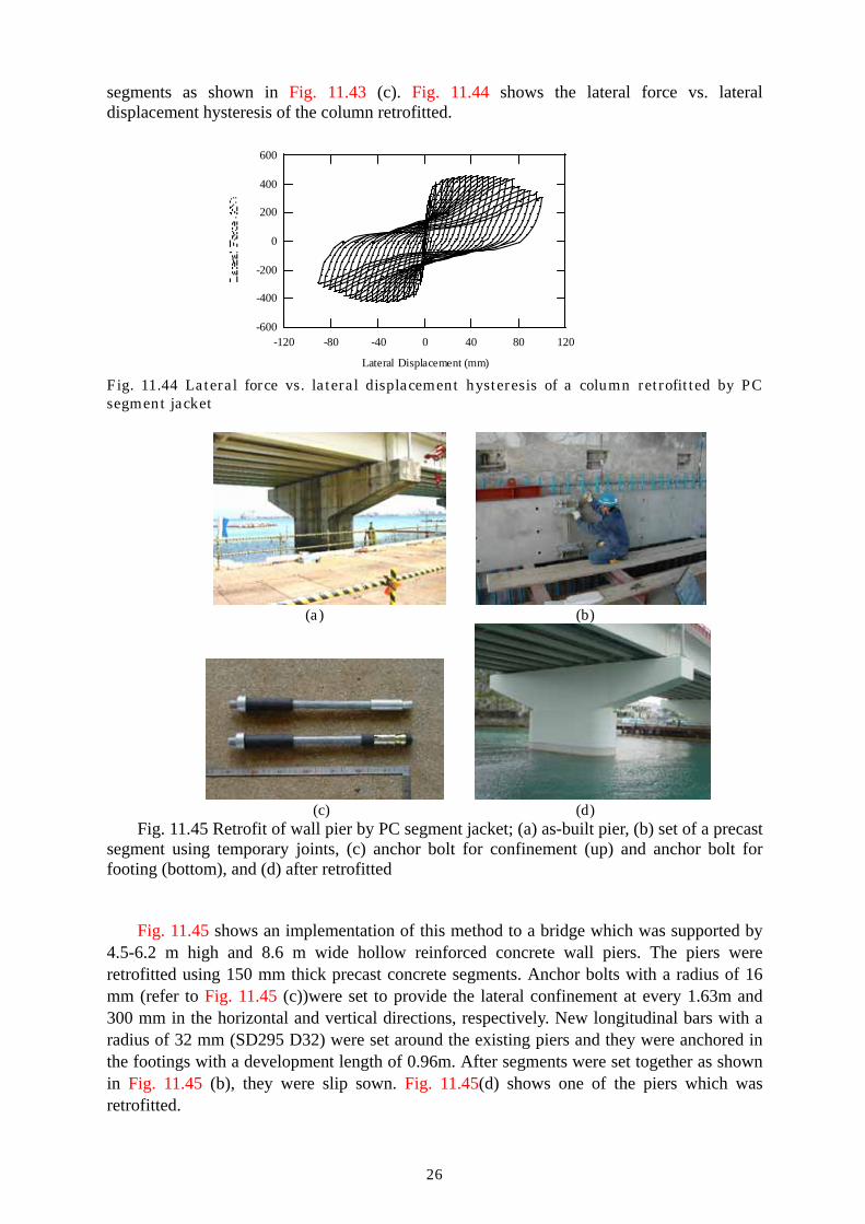
segments as shown in Fig. 11.43 (c). Fig. 11.44 shows the lateral force vs. lateral displacement hysteresis of the column retrofitted.
-600
-400
-200
0
200
400
600
-120 -80 -40 0 40 80 120
Lateral Displacement (mm) Fig. 11.44 Lateral force vs. lateral displacement hysteresis of a column retrofitted by PC segment jacket
(a) (b)
(c) (d)
Fig. 11.45 Retrofit of wall pier by PC segment jacket; (a) as-built pier, (b) set of a precast segment using temporary joints, (c) anchor bolt for confinement (up) and anchor bolt for footing (bottom), and (d) after retrofitted
Fig. 11.45 shows an implementation of this method to a bridge which was supported by
4.5-6.2 m high and 8.6 m wide hollow reinforced concrete wall piers. The piers were retrofitted using 150 mm thick precast concrete segments. Anchor bolts with a radius of 16 mm (refer to Fig. 11.45 (c))were set to provide the lateral confinement at every 1.63m and 300 mm in the horizontal and vertical directions, respectively. New longitudinal bars with a radius of 32 mm (SD295 D32) were set around the existing piers and they were anchored in the footings with a development length of 0.96m. After segments were set together as shown in Fig. 11.45 (b), they were slip sown. Fig. 11.45(d) shows one of the piers which was retrofitted.
27
11.3 Retrofit of beam-column joints 11.3.1 Retrofit of cap beams
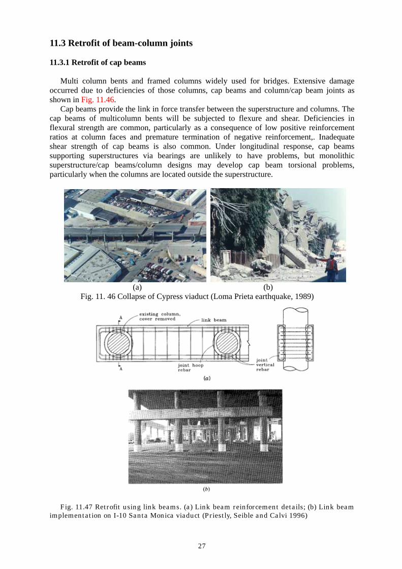
Multi column bents and framed columns widely used for bridges. Extensive damage occurred due to deficiencies of those columns, cap beams and column/cap beam joints as shown in Fig. 11.46.
Cap beams provide the link in force transfer between the superstructure and columns. The cap beams of multicolumn bents will be subjected to flexure and shear. Deficiencies in flexural strength are common, particularly as a consequence of low positive reinforcement ratios at column faces and premature termination of negative reinforcement,. Inadequate shear strength of cap beams is also common. Under longitudinal response, cap beams supporting superstructures via bearings are unlikely to have problems, but monolithic superstructure/cap beams/column designs may develop cap beam torsional problems, particularly when the columns are located outside the superstructure.
(a) (b)
Fig. 11. 46 Collapse of Cypress viaduct (Loma Prieta earthquake, 1989)
Fig. 11.47 Retrofit using link beams. (a) Link beam reinforcement details; (b) Link beam implementation on I-10 Santa Monica viaduct (Priestly, Seible and Calvi 1996)

28
Cap beam deficiencies can be difficult and expensive to alleviate. Two basic approaches
may be adopted: The cap beam strength can be increased to the level required to sustain the column plastic hinges, or the seismic forces developed in the cap beam can be reduced by a number of means. When cap beams and particularly column/cap joint forces induced by seismic action severely exceed capacity, it may be worth considering means for cap beam force reduction. As shown in Fig. 11.47, if located high on the columns, the link beam is effective in reducing seismic force in the cap beam. The link beam should be constructed by removing the column cover concrete over the height of the link beam and using a link beam width sufficient to place the longitudinal reinforcement outside the column core.
Generally, the retrofit philosophy of cap beams will be to increase the cap beam flexural strength sufficiently to force plastic hinge into the columns. With a separate cap beam supporting the superstructure via bearings, as shown in Fig. 11.48 (a), flexural strengthening can be achieved by adding reinforced concrete bolsters to the sides after roughening the interface. The new and old concrete should be connected by dowels, preferably passing right through the existing cap beam.
Fig. 11.48 Flexural and shear retrofit of cap beam. (a) Bearing-supported superstructure; (b) Integral cap beam (Priestley, Seible and Calvi 1996)
An alternative or supplemental means of flexural strength enhancement is to prestress the
cap beam using strong-backs at the cap beam ends. The prestress may be inside bolsters as show in Fig. 11.48 (a), or using external prestressing without bolsters. Enhancing the flexural capacity of integral cap beam as shown in Fig. 11.48(b) is more difficult because of physical constraints imposed by the existing superstructure. Bolsters may be added at the bottom to enhance positive moment capacity, and negative moment capacity can be increased by removing the top concrete and adding additional reinforcement.
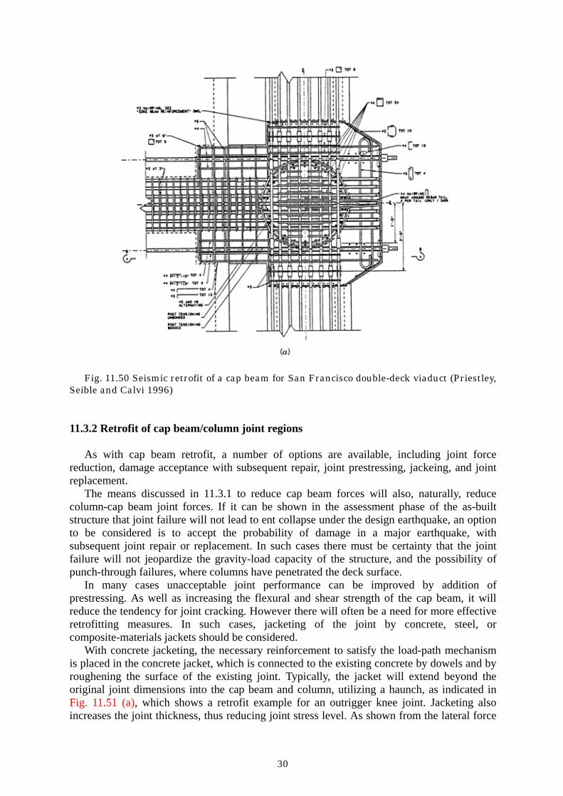
Full or partial-depth bolsters can be reinforced with transverse reinforcement to enhance cap beam shear strength as indicated in Fig. 11.48. Prestressing will also enhance the cap beam shear strength. Tests on a large-scale model of a retrofit concept for the San Francisco double-deck viaducts following the Loma Prieta earthquake (Priestley et al 1993a, Priestley et al 1993b), which incorporated cap beam presterssing to enhance flexural and shear strength of the existing cap beam and edge beams as shown in Fig. 11.49, indicated that the

29
approaches for flexure and shear enhancement were dependable and conservative. Fig. 11.50 shows cap beam retrofit details.
(a) (b)
(c) (d)
(e) (f)
Figure 11.49 Retrofit of San Francisco double-deck viaducts using edge link beams; (a) as-built viaduct, (b) proof test model, (c) proof test, (d) column damage in the proof test, (d) retrofit, and (e) edge beams
Cap beam shear strength may also be enhanced by composite materials bonded to the
sides of the cap beam. This will be most effective when the composite layer can be wrapped around the top and soffit of the cap beam, as will be generally the case for bearing-supported superstructures.
30
Fig. 11.50 Seismic retrofit of a cap beam for San Francisco double-deck viaduct (Priestley, Seible and Calvi 1996)
11.3.2 Retrofit of cap beam/column joint regions As with cap beam retrofit, a number of options are available, including joint force
reduction, damage acceptance with subsequent repair, joint prestressing, jackeing, and joint replacement.
The means discussed in 11.3.1 to reduce cap beam forces will also, naturally, reduce column-cap beam joint forces. If it can be shown in the assessment phase of the as-built structure that joint failure will not lead to ent collapse under the design earthquake, an option to be considered is to accept the probability of damage in a major earthquake, with subsequent joint repair or replacement. In such cases there must be certainty that the joint failure will not jeopardize the gravity-load capacity of the structure, and the possibility of punch-through failures, where columns have penetrated the deck surface.
In many cases unacceptable joint performance can be improved by addition of prestressing. As well as increasing the flexural and shear strength of the cap beam, it will reduce the tendency for joint cracking. However there will often be a need for more effective retrofitting measures. In such cases, jacketing of the joint by concrete, steel, or composite-materials jackets should be considered.
With concrete jacketing, the necessary reinforcement to satisfy the load-path mechanism is placed in the concrete jacket, which is connected to the existing concrete by dowels and by roughening the surface of the existing joint. Typically, the jacket will extend beyond the original joint dimensions into the cap beam and column, utilizing a haunch, as indicated in Fig. 11.51 (a), which shows a retrofit example for an outrigger knee joint. Jacketing also increases the joint thickness, thus reducing joint stress level. As shown from the lateral force

31
vs. displacement response in Fig. 11.51 (b), this form of retrofit can be completely effective. In this knee-joint example, plastic hinging formed in the column, and the limit to response was caused by a confinement failure in the column at moderately high curvature ductility factors.
Fig. 11.51 Concrete jacketing of a deficient knee joints; (a) concrete jacket with an
haunch, and (b) lateral force vs. displacement hysteresis (Priestley et al 1996)
Similar improvements in joint behavior have been obtained with steel jackets epoxy bonded to the concrete surface connected through the joint thickness with through-bolts to assist in the transfer of the joint force resistance mechanism from the outer steel plates to the beam and column stress resultants,

32
11.4 Retrofit of foundations 11.4.1 Introduction
Because retrofit of a foundation is much costly than the retrofit of a column and a pier, a
strategy of seismic retrofit which does not require the retrofit of the foundation should be sought first. Retrofit measures which do not increase the demand of a foundation are most appropriate for this purpose. However foundations have to be properly retrofitted if this is inevitable. Retrofit strategy for enhancing only the capacity of piers and columns which results in unbalance of total bridge system should be avoided.
Similar to the practice to columns and piers, there are several deficiencies in design of foundations. Because driving force of piles was limited at the early days, radius and lengths of piles were generally insufficient based on the current design criteria. Large radius cast-in-place piles were not yet developed. Connection of piles to footing was always weak or insufficient, and this results in overturning or excessive uplift of the footing during an earthquake. Similar to columns insufficient lap splices are often used in piles.
Footings designed in the early days have generally insufficient shear and flexural strength. Because seismic force was not regarded as a main design force prior to the 1971 San Fernando, USA earthquake, footings were not adequately reinforced along the top surface.
Instability of soils around the foundations results in extensive failure during an earthquake. Failure of clayey soils and soil liquefaction are major sources of thread to foundations. Lateral spreading associated with soil liquefaction resulted in extensive damage in the past earthquakes.
Because retrofit of foundations has to be mostly conducted under water, construction works become considerable. Construction of an access road to the foundations is sometimes as costly as the retrofit jobs. Because enhancing the shear and flexural capacity of piles by jacketing is difficult, additional piles are generally droved around the existing footings. Because piles have to be drove under the deck, space limitation results in narrowed selection of construction procedure.
Compared to the retrofit of columns and piers, retrofit of foundations is so far limited. However various new technologies are being developed. 11.4.2 Retrofit of foundations to instability of surroundings soils
Instability of soils surrounding footings resulted in extensive damage in the past earthquakes. Effect of soil liquefaction and lateral spreading was not known and it was not considered in design of the bridges in the early days. The bridges which were designed at the early days without taking those effects into account and were built at the sites where extensive soils liquefaction and lateral spreading are likely to occur are particularly vulnerable.
Retrofit of foundations under such a condition is extensively difficult, because all components including shear, flexural and ductility capacity of piles and footings are mostly insufficient. Consequently, whole foundations have to be retrofitted in most cases.
Fig. 11.52 shows an example of seismic retrofit of pile foundations in a 238 m long 14-span simply supported bridge. Footigs were supported by 24 precast concrete piles with a radius of 250 mm. Because bearing capacity of soils around the foundations was insufficient, two methods were clarified for retrofit. The first was to construct new piles by exdending the existing footing. The other was to improve soils around the foundation so that level of seismic risk due to soil liquefaction could be mitigated. Because soils improvement was more costly and difficult to assure the risk reduction, the first option was appropriate. However

33
space limitation made it difficult for driving new piles in the first option. Consequently, a combination of the construction of new piles and the soil improvement was adopted in this bridge.
Fig. 11.52 Seismic retrofit of a pile foundation by new piles and an extension of footing
Fig. 11.53 Seismic retrofit of a pile foundation by new piles and an extension of footing Four new 14 m long cast-in-place piles with a radius of 800 mm were built at the corners
of the footing. To extend the footing, the covering concrete of existing footings was chipped out and anchor bars with a radius of 22 mm were inserted into drilled holes with epoxy resin grouting. Cement milk was grouted into the surrounding ground to improve the soil strength

34
up to 3m deep below the bottom of the footing. The footing was extended almost twice the original in thickness and the length in the longitudinal direction.
Fig. 11.53 shows another example of seismic retrofit of pile foundations in 30m thick soft clayey soils. Because the bearing capacity of clayey soils was insufficient, six new piles were constructed by expanding the footing. A difficult point of this retrofit was the space limitation of upper level of the footing. Because of river flow, the thickness of overlaying the footing on its upper surface was limited. Consequently it was needed to build the footing not only on the existing footing but also under the footing. Special excavation under the existing footing was needed and it was costly.
Fig. 11.54 Seismic retrofit of a 11-span simply supported bridge in liquefiable sandy soils by edge beams
In addition to direct retrofit of foundations, there are alternative approaches for retrofit of
bridges on unstable soils. Fig. 11.54 shows a seismic retrofit of an 11-span simply-supported pre-tensioned concrete slab bridge. Used were reinforced concrete bent plies with 12 m long and 600 mm in radius, which were vulnerable to soil liquefaction.
Five approaches were clarified for retrofit; (1) retrofit all 12 substructures, (2) retrofit every other substructures, (3) retrofit abutments at both ends and connect all bent piers to the abutments by two edge beams, (4) replace soils vulnerable to liquefaction, and (5) improve liquefiable soils by the chemical grouting. Because the options (4) and (5) were costly in spite of unreliable effectiveness, they were eliminated. Among the remaining three options, (3) was finally adopted because the cost vs. performance was most appropriate.
The bridge was designed so that all seismic lateral force of the decks in the longitudinal direction is supported by two abutments. Two edge beams were built along the bridge and the inertia force of the decks were transfer by the edge beams to the end abutments. The edge beams were connected to the top of each bent pile by fixed bearings. The edge beams were used as pedestrian paths.
35
10.4.3 Shear and flexure retrofit of footings
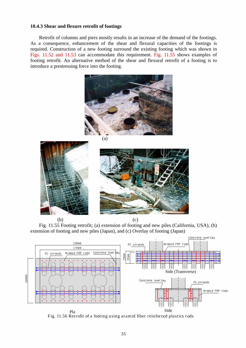
Retrofit of columns and piers mostly results in an increase of the demand of the footings. As a consequence, enhancement of the shear and flexural capacities of the footings is required. Construction of a new footing surround the existing footing which was shown in Figs. 11.52 and 11.53 can accommodate this requirement. Fig. 11.55 shows examples of footing retrofit. An alternative method of the shear and flexural retrofit of a footing is to introduce a prestressing force into the footing.
(a)
(b) (c) Fig. 11.55 Footing retrofit; (a) extension of footing and new piles (California, USA), (b)
extension of footing and new piles (Japan), and (c) Overlay of footing (Japan)
Fig. 11.56 Retrofit of a footing using aramid fiber reinforced plastics rods
Aramid FRP rods
PC strandsConcrete overlay
Side
2500
Concrete overlay
Aramid FRP rods PC strands
Side (Transverse)
2800
平面図
19000 17000
10000
Aramid FRP rods PC strands Concrete Overlay
Pla

36
Shear and flexural retrofit of 2.5 m thick footings was conducted using aramid fiber
reinforced plastics rods at a bridge supported by 8-12.5 m tall circular reinforced concrete columns with a radius of 3m. Flexural yield and shear failure were anticipated if the footings are subjected to compression from the piles. Extension of the footings with new piles was costly and overlaying of the footings at its top was restricted due to space limitation for ship transportation. As a consequence, the footings were retrofitted by introducing prestressing force in the vertical and lateral directions as shown in Fig. 11.56. The vertical prestresing was required to enhance the shear capacity while the lateral prestrsssing was required to enhance both the shear and flexural capacities of the footings.
The lateral prestressing was provided by PC strands. On the other hand, aramid fiber reinforced plastics rods were used for the vertical prestressing. There were three reasons in the adoption of the aramid fiber rods. The first is lower elastic modulus of aramid fiber rods than PC strands. It was appropriate to stably introduce and maintain the prestresing force in the 2.5 m thick footings. The second was smaller radius of drilled holes required to set aramid fiber rods which reduced risk of cutting existing rebars by drills. The third is that aramid fiber rods are durable under sea.
(a) (b)
(c) Fig.11.57 Retrofit of a footing using aramid fiber reinforced plastics rods; (a) as-built
bridge, (b) aramid fiber reinforced plastics rods, and (c) aramid fiber reinforced plastics rods installed in the footing in the vertical direction

37
Fig. 11.57 shows the setting of aramid fiber rods in the retrofit of the footings. After the
foundations were dried up, holes with a radius of 60 mm were drilled into 2.3 m deep from the surface of the footings. Nine aramid fiber rods with a radius of 7.4 mm were set per hole and they were anchored by a special resign. Pretension force was introduced in the aramid fiber rods.
11.4.4 Cost-effective dry-up construction method
As shown in the above retrofit examples, major obstacle for the retrofit of columns and foundations under water is high cost involved in dry-up around the foundations. The dry us is generally very costly and its cost is sometimes more or less the same with the cost for retrofit. Because foundations have to be retrofitted under the deck, only limited space is usually available which narrows the option of retrofit methods. Long construction period for construction is also a problem of dry up.
Several attempts are being conducted to reduce the cost and construction period of dry up foundations. For example, prefabricated steel segments which can be easily transported to assemble at the site around the columns make the construction period and cost much reduced. Fig. 11.58 shows an example of implementation of this method to a bridge which are supported by 12.2 m tall circular RC columns with a radius of 4.4m. Steel segments which were transported to the site were assembled around the columns. Construction cost at this site was only a nearly half compared to the standard dry-up method. The segments can be re-used at other construction sites.
(a) (b)
Fig. 11.58 Implementation of steel segment dry-up method; (a) assembling test, and (b)
assembling the segments around the foundation
11.4.5 Micro piles
Limited space under the deck generally makes it difficult to drive new piles for retrofit of foundations. Micro piles as shown in Fig. 11.59 are increasingly used for retrofit of foundations where only limited space is available. Various types of micro piles are available (Nishitani et al 2002). Deformed rebars are used for micro piles which carry less heavy load while steel tubes with and without deformed rebars are used for micro piles which carry heavy load. If a space of 3.5 m high and 2.5 m wide is available, micro piles as long as 50 m with a radius of 150-300 mm can be drove. Bearing capacity of micro piles can be as large as 1 MN per pile.
Fig. 11.60 shows an example of driving micro piles for retrofit of foundations (Nishitani et al 2002). There were two reasons to adopt the micro piles in this bridge in addition to the

38
space limitation. The first is that micro piles could be constructed without suspending the traffic of this bridge. Because this was an important bridge in the region, this condition was extremely important in the selection of this retrofit method. The other is the less amount of water pollution on fishery. Any other alternative retrofit methods such as the extension of footings and driving new large radius cast-in-pace piles could pollute water.
Figure 11.59 Micro pile retrofit of pile foundation
(a) (b)
Fig. 11.60 Micro piles for retrofit of foundations; (a) drilling and (b) micro piles after installed
(a) (b) (c) (a) (b) (c)
Fig. 11.61 Comparison of retrofit cost; (a) standard new pile & footing extension, (b) micro-piles (straight), and (c) micro-piles (inclined)
39
Table 11.2 shows an evaluation of construction cost and period of retrofit of a bridge for 3 options as shown in Fig. 11.61. Because radius of micro piles is much smaller than the radius of cast-in-place piles, cost and period saving of micro piles retrofit is acceptable.
Table 11.2 Cost evaluation of retrofit using micro piles
Properties and cost Cast-in-place piles
Straight micro piles
Inclined micro piles
Radius of piles 1000m 178mm 178mm Number of piles 8 26 14 Length of piles 16m 21m 21m Cost of piles relative to cast-in-place piles
100% 90% 80%
Total cost of retrofit including dry-up and footing retrofit
100% 81% 72%
Construction period relative to cast-in-place piles
100% 80% 65%
11.4.6 Retrofit of abutments
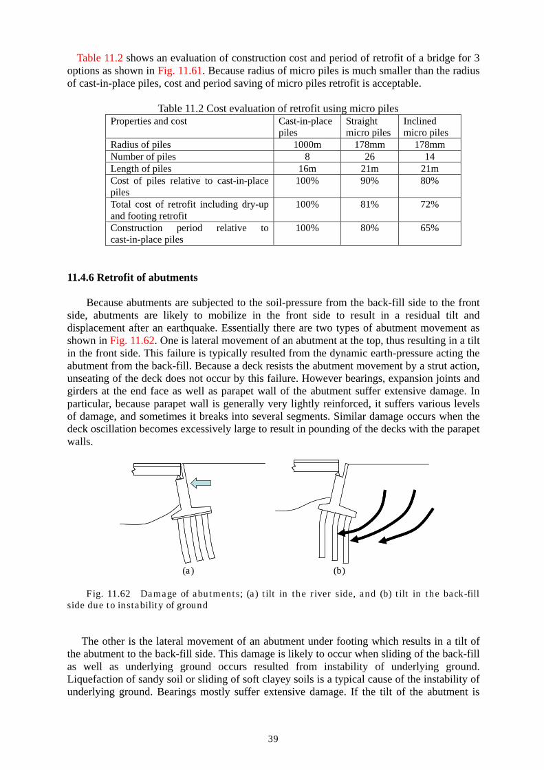
Because abutments are subjected to the soil-pressure from the back-fill side to the front side, abutments are likely to mobilize in the front side to result in a residual tilt and displacement after an earthquake. Essentially there are two types of abutment movement as shown in Fig. 11.62. One is lateral movement of an abutment at the top, thus resulting in a tilt in the front side. This failure is typically resulted from the dynamic earth-pressure acting the abutment from the back-fill. Because a deck resists the abutment movement by a strut action, unseating of the deck does not occur by this failure. However bearings, expansion joints and girders at the end face as well as parapet wall of the abutment suffer extensive damage. In particular, because parapet wall is generally very lightly reinforced, it suffers various levels of damage, and sometimes it breaks into several segments. Similar damage occurs when the deck oscillation becomes excessively large to result in pounding of the decks with the parapet walls.
(a) (b)
Fig. 11.62 Damage of abutments; (a) tilt in the river side, and (b) tilt in the back-fill
side due to instability of ground
The other is the lateral movement of an abutment under footing which results in a tilt of the abutment to the back-fill side. This damage is likely to occur when sliding of the back-fill as well as underlying ground occurs resulted from instability of underlying ground. Liquefaction of sandy soil or sliding of soft clayey soils is a typical cause of the instability of underlying ground. Bearings mostly suffer extensive damage. If the tilt of the abutment is

40
large, unseating of the deck from the abutment occurs. In the past, the first type damage was dominant with several examples of the second
damage. Because damage resulted from failure of abutment is generally restricted to the ends of the girder, expansion joints, bearings and parapet wall, it has been regarded as a secondary damage compared to the damage of columns and piers and deck. However once abutments suffer damage, the function of a bridge to traffic is deteriorated or lost and it takes long period for repair.
Similar to retaining wall, the most essential retrofit of abutments is to enhance the strength of abutments. Retrofit has been conducted by enlarging the footing and constructing new piles. Enhancement of soil strength by soil replacement or cement mixing is also widely accepted for tilt resulted from instability of underlying ground. Earth-anchors are frequently used for the tilt of abutments in the front direction,.
A unique retrofit for tilt of an abutment in the front direction is to partly replace the back-fills with expanded polystyrene (EPS) blocks as shown in Fig. 11.63. Because use of EPS blocks reduces the dynamic earth-pressure of the back-fills to an abutment, damage of the abutment during an earthquake can be mitigated. For example, 1.75 m high and 13 m long EPS blocks replaced the back fill behind an abutment to decrease the dynamic earth-pressure.
Fig. 11.63 EPS retrofit of abutments
11.5 Retrofit of superstructures
Because superstructures are designed for dead load and traffic load considering large safety factors, their direct damage resulted from the seismic effect is not generally as severe as the substructures. However the members in the vicinity of bearing and at the end of the superstructures are vulnerable. For example, Fig. 11.64 shows damage of decks at an intermediate hinge resulting pounding.
Most common retrofit for superstructures is installation of unseating prevention devices. The unseating prevention devices were first developed after the 1964 Niigata earthquake. Various unseating prevention devices are now used worldwide. They may be classified into four groups; (1) extension of a seat, (2) connection of decks to substructure, (3) connection between decks at the edges, and (4) connection of decks at an intermediate hinge. There are connectors which resist only tension such as cable restrainers, and connectors which resist both tension and compression. Fig. 11.65 and Fig. 11.66 show typical unseating prevention devices.

41
Fig. 11.64 Damage of intermediate joint due to pounding (1994 Northridge earthquake)
(a) Concrete Bracket (b) Steel Bracket
(1) Extension of Seat Length
(a) Cable restrainer (b) Steel ties © PC strands
(2) Connection of decks to substructure
(a) Steel decks(b) Concrete decks
(3) Connection between Decks
(a) Concrete Bracket (b) Steel Bracket
(1) Extension of Seat Length
(a) Cable restrainer (b) Steel ties © PC strands
(2) Connection of decks to substructure
(a) Steel decks(b) Concrete decks
(3) Connection between Decks
Fig. 11.65 Typical unseating prevention devices

42
(a) (b)
Fig. 11.66 Installation of cable restrainers (California department of transportation)

43
11.6 Retrofit using dampers and isolation 11.6.1 Introduction
Mitigation of seismic response of bridges using dampers and seismic isolation is an alternative approach to seismic retrofit. If the seismic response of a bridge can be mitigated by using dampers to a level which does not require any direct retrofit of structural components under the design ground motions, there must be tremendous benefit in the cost and period of seismicretrofit. No matter how the use of dampers and seismic isolation does not bring the bridge response to the level which does not require any seismic retrofit, benefit still exists if reasonable amount of mitigation of seismic response can be achieved. Because direct retrofit of foundations is costly, it is expected to develop appropriate measures which enable to avoid direct retrofit of foundations by using dampers and seismic retrofit.
There are variety of applications of dampers and seismic isolations for seismic retrofit. Some are direct application based on the original concept of seismic isolation, and the others are indirect application. Some examples of retrofit using dampers and seismic retrofit are presented here.
11.6.2 Retrofit using seismic isolation
Seismic isolation is effective for not only new bridges but also existing bridges. However there are several restrictions in the implementation of isolation technologies to existing bridges. The first is the restriction on the leveling of bridge surface. Replacing the existing steel bearings with new elastomeric bearings with energy dissipating capacity such as the lead rubber bearings and high damping rubber bearings is likely to increase the leveling of the bridge. Because change of leveling of bridge surface is generally restricted, alternative approaches have to se sought. The second is the restriction on the amount of gaps between adjacent decks. Because larger deck displacement resulted from the period shift is needed to dissipate energy in the seismic isolation, gaps between two adjacent decks must be large enough. However this is mostly difficult in the existing bridges.
Fig. 11.67 Unbond brace damper An analytical study on the effectiveness of seismic isolation for retrofit was conducted to
three span simply supported bridges with a span length of 26m each which were subjected to the JMA Kobe ground acceleration (PGA=0.87g) measured during the 1995 Kobe, Japan earthquake. The bridge was supported by four 7.5-11.3 m tall reinforced concrete columns. The bridges were originally supported by steel fixed and movable bearings, but they were replaced with high damping rubber bearings. Because deck displacement increased in the seismic isolation, unbond brace dampers as shown in Fig. 11.67 were installed at every supports. The unbond dampers consisted of an energy dissipating unit and a casing which
Energy dissipator due to plastic deformation
Casing for Buckling Prevention

44
constrained the buckling of energy dissipating unit. As shown in Fig. 11.68, the 7.5 m tall column in the as-built bridge exhibits extensive hysteretic response while the same column shows linear response when the bridge is retrofitted using isolation and unbond brace dampers. The peak shear force at the foundation decreases to 91% the response of the existing bridge. The peak deck displacement of the retrofitted system is 164 mm which is 72% the unretrofitted system of 227 mm.
-20
-10
0
10
20
-0.04 -0.02 0 0.02 0.04
Mom
ent (
MN
m)
Curvature (1/m)
-20
-10
0
10
20
-0.04 -0.02 0 0.02 0.04
Mom
ent (
MN
m)
Curvature (1/m) (a) (b)
Fig. 11.68 Effect of isolation and unbond brace dampers; (a) as-built bridge, and (b) isolated bridge with unbond brace dampers
(a) Existing (b) Retrofitted
Steel Bearings
Dampers(LRB or HDR)
Friction Bearings
Extension of Cap Beam
(a) Existing (b) Retrofitted
Steel Bearings
Dampers(LRB or HDR)
Friction Bearings
Extension of Cap Beam
Fig. 11.69 Seismic retrofit using isolation
Dampers
Sliding Bearings
Extended Pier
(a) (b)
Fig. 11.70 Seismic retrofit using seismic isolation; (a) installation of lead rubber bearings and sliding bearings, and (b) after retrofitted
Fig. 11.69 shows an implementation of seismic isolation to retrofit of existing bridges.
Because existing steel bearings were vulnerable to damage they were replaced with lead rubber bearings. The existing steel bearings were remained to carry the dead weight of the

45
superstructure by removing stoppers so that they functioned as sliding bearings. The lead rubber bearings were installed to provide the lateral restoring force and energy dissipation capability.
Several bridges supported by frame piers were retrofitted using this method. Only a part of existing steel bearings was replaced with new sliding bearing so that the deck can move in the longitudinal direction as shown in Fig. 11.70. After extending the seat, lead rubber bearings were installed. Fig. 11.70(b) shows the bridge after retrofitted.
Fig. 11.71 shows another application of lead rubber bearings to change the bridge supporting system from several span simply supported bridges to a multi-span continuous bridge. There are a number of simply supported bridges which have maintenance problem at expansion joints due to traffic load. Consequently connecting adjacent decks together is beneficial for reducing maintenance cost. Because unseating of a deck occurs at the ends of the deck, the connection of adjacent decks reduces the risk of unseating of a bridge during an earthquake.
Therefore existing steel fixed and movable bearings were replaced by lead rubber bearings or high damping rubber bearings as show in Fig. 11.71. Simply supported decks were tied together after removing the existing expansion joints so that the bridge responds as a multiple-span continuous bridge during an earthquake.
(a) Removal of Existing Steel Bearings (b) Set of New Elastomeric Lead Rubber
Bearings Fig. 11.71 Connection of decks and retrofit; (a) removal of existing steel bearings, and
(b) set of new lead rubber bearing
11.6.3 Retrofit using brace dampers Installation of new dampers mitigates the seismic response of a bridge during an
earthquake. Various dampers can be effective for this purpose. Because a bridge substructure is much larger in section and stiffer than buildings, deformation in a substructure is smaller. Therefore stiffer dampers are required for retrofit of a bridge. Brace dampers and unbond brace dampers are increasing used in recent years from this reason.
For example, single frame piers have been used for a standard viaduct in railways including Shin-kansen (bullet train) in Japan. Because this type of viaduct suffered extensive shear and flexural failure in the past earthquakes, seismic retrofit is required. However space limitation around the viaducts sometimes does not allow to retrofit the viaducts by steel or composite materials jacketing. Consequently, a compression brace damper which consists of four steel shear panel dampers and four X-shape braces as shown in Fig. 11.72 was developed and it has been successfully implemented for retrofit (Yoshida et al 2005). The panel dampers are designed so that they dissipate energy once they yield in shear. When shear panels deform, the damper consisting of four shear panels, which is so designed to have an
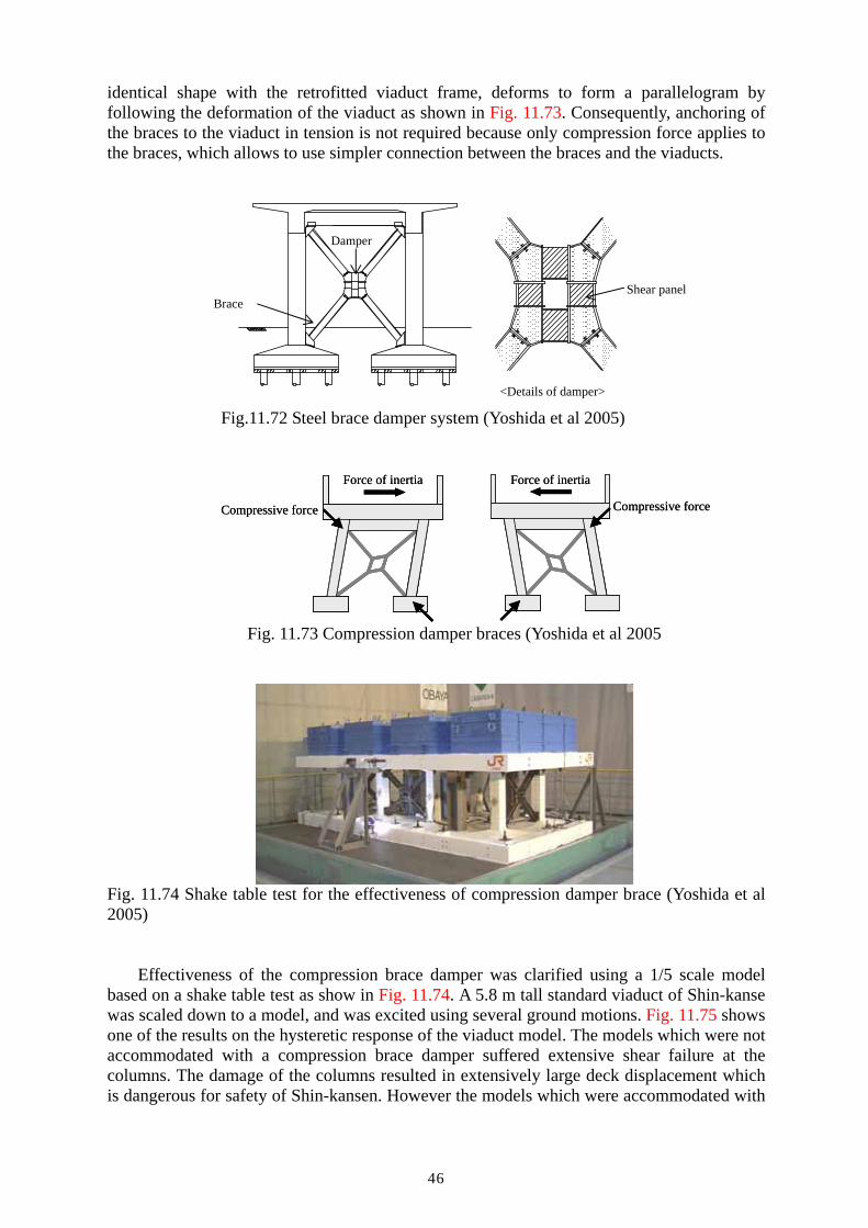
46
identical shape with the retrofitted viaduct frame, deforms to form a parallelogram by following the deformation of the viaduct as shown in Fig. 11.73. Consequently, anchoring of the braces to the viaduct in tension is not required because only compression force applies to the braces, which allows to use simpler connection between the braces and the viaducts.
Damper
Brace Shear panel
<Details of damper>
Fig.11.72 Steel brace damper system (Yoshida et al 2005)
Compressive force
Force of inertia Force of inertia
Compressive force Compressive force
Force of inertia Force of inertia
Compressive force
Fig. 11.73 Compression damper braces (Yoshida et al 2005
Fig. 11.74 Shake table test for the effectiveness of compression damper brace (Yoshida et al 2005)
Effectiveness of the compression brace damper was clarified using a 1/5 scale model
based on a shake table test as show in Fig. 11.74. A 5.8 m tall standard viaduct of Shin-kanse was scaled down to a model, and was excited using several ground motions. Fig. 11.75 shows one of the results on the hysteretic response of the viaduct model. The models which were not accommodated with a compression brace damper suffered extensive shear failure at the columns. The damage of the columns resulted in extensively large deck displacement which is dangerous for safety of Shin-kansen. However the models which were accommodated with
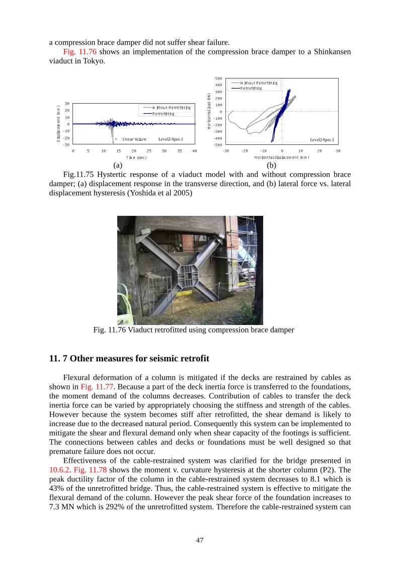
47
a compression brace damper did not suffer shear failure. Fig. 11.76 shows an implementation of the compression brace damper to a Shinkansen
viaduct in Tokyo.
-30
-20
-10
0
10
20
30
0 5 10 15 20 25 30 35 40
Time (sec)
Displacement (mm) Without Retrofitting
Retrofitting
Level2-Spec.I← Shear failure-500
-400
-300
-200
-100
0
100
200
300
400
500
-30 -20 -10 0 10 20 30
Horizontal displacement (mm)
Horizontal load (kN)
Without RetorfittingRetrofitting
Level2-Spec.I
(a) (b)
Fig.11.75 Hystertic response of a viaduct model with and without compression brace damper; (a) displacement response in the transverse direction, and (b) lateral force vs. lateral displacement hysteresis (Yoshida et al 2005)
Fig. 11.76 Viaduct retrofitted using compression brace damper
11. 7 Other measures for seismic retrofit
Flexural deformation of a column is mitigated if the decks are restrained by cables as shown in Fig. 11.77. Because a part of the deck inertia force is transferred to the foundations, the moment demand of the columns decreases. Contribution of cables to transfer the deck inertia force can be varied by appropriately choosing the stiffness and strength of the cables. However because the system becomes stiff after retrofitted, the shear demand is likely to increase due to the decreased natural period. Consequently this system can be implemented to mitigate the shear and flexural demand only when shear capacity of the footings is sufficient. The connections between cables and decks or foundations must be well designed so that premature failure does not occur.
Effectiveness of the cable-restrained system was clarified for the bridge presented in 10.6.2. Fig. 11.78 shows the moment v. curvature hysteresis at the shorter column (P2). The peak ductility factor of the column in the cable-restrained system decreases to 8.1 which is 43% of the unretrofitted bridge. Thus, the cable-restrained system is effective to mitigate the flexural demand of the column. However the peak shear force of the foundation increases to 7.3 MN which is 292% of the unretrofitted system. Therefore the cable-restrained system can

48
be implemented when the foundation has sufficient shear capacity.
Fig. 11.77 External cable-restrained system
-20
-10
0
10
20
-0.04 -0.02 0 0.02 0.04
Mom
ent (
MN
m)
Curvature (1/m)
-20
-10
0
10
20
-0.04 -0.02 0 0.02 0.04
Mom
ent (
MN
m)
Curvature (1/m) (a) (b)
Fig. 11.78 Effect of external cable-restrained system on the plastic curvature at P2; as built and (b) retrofitted by external cable-restrained system
Fig. 11.79 School building retrofitted by external cable-stayed system (Watanabe, to be published)
Although the cable-restrained system has not yet been implemented to bridges, a similar
concept was implemented to a school building as shown in Fig. 11.79 (Watanabe et al 2006). Similar to cable-stayed bridges, the foundation beam is restrained by parallel cables which are anchored to a central reinforced concrete tower.
A 232 m long bridge consisting of 14.15 m long simply supported decks was retrofitted

49
by steel pipe arches which were built under the decks as shown in Fig. 11.80 (Mizuta and Hashimoto 2001). This arch-restrained system transfers the deck inertia force to the foundations by arches.
The effectiveness of this method was clarified for the four span simply supported bridge which was shown above. Unbond brace dampers which are shown in Fig. 11.67 were installed between the deck and the crown of the arch at every span. The deck displacement is only 23 mm which is 10% of the as-built bridge. Consequently the column stays in elastic range as shown in Fig. 11.81. However similar to the cable-restrained system, the peak shear force at the foundation increases to 4.23 MN which is 169% of the as-built bridge. Therefore the arch-restrained system is effective to mitigate the moment and ductility demand of the columns if the foundations have sufficient shear capacity.
(a) (b)
(c) (d) Fig. 11.80 Retrofit of a simply supported bridge using pipe arches; (a) before retrofit,
(b) after retrofit, (c) pipe arches, and (d) connection between arches and a foundation (Mizuta and Hashimoto, 2001)

50
-20
-10
0
10
20
-0.04 -0.02 0 0.02 0.04
Mom
ent (
MN
m)
Curvature (1/m)
-20
-10
0
10
20
-0.04 -0.02 0 0.02 0.04
Mom
ent (
MN
m)
Curvature (1/m) (a) (b)
Fig. 11.81 Effect of pipe arch system; (a) as-built an (b) retrofitted by pipe arches
Acknowledgements
Invariable materials and information were provided from many personnel and organizations. Special appreciation is delivered to Fujimoto, Y. (Fuji PS), Fukui, J. (Public Works Research Institute), Fujiwara, Y. (Sumitomo Mitsui Construction), Iida, Y. (Obayashi Construction), Mizuta, Y. (Professor, Kyusyu Sangyo University), Mori (PS Mitsubishi), Okano, M. (Obayashi Construction), Unjoh, S. (Public Works Research Institute), Watanabe, F. (Professor, Kyoto University), Watanabe, H. (Kawada Kensetsu), References Akimoto, T., Nakajima, H. and Kogure, F. (1990) “Seismic strengthening of reinforced
concrete piers on Metropolitan expressway,” Proc. 1st US-Japan Workshop on Seismic Retrofit of Bridges, 280-298, Tsukuba Science City, Japan.
Chai, Y.H., Priestley, N.M.J., and Seible, F. (1990) “Retrofit of bridge columns for enhanced seismic performance,” Proc. 1st US-Japan Workshop on Seismic Retrofit of Bridges, 321-340, Tsukuba Science City, Japan.
Kato, S., Sato, H., Nakai, H. and Fujita, M. (2001) “Seismic retrofit of Oga bridge using aramid fiber reinforced plastics,” Civil Engineering Construction, 17-22.
Kawashima, K. (1990) “Seismic design, seismic strengthening and repair of highway bridges in Japan,” Proc. 1st US-Japan Workshop on Seismic Retrofit of Bridges, 3-61, Tsukuba Science City, Japan.
Kawashima, K., Unjoh, S. and Mukai, H. (1994) “Seismic strengthening of highway bridges,” 2nd US-Japan Workshop on Seismic Retrofit of Bridges, 1-36, Report No. UCB/EERC 97/09, Earthquake Engineering Research Center, University of California, Berkeley, USA.
Kawashima, K., Hosotani, M. and Yoneda, K.: Carbon fiber sheet retrofit of reinforced concrete bridge piers, Proc. International Workshop on Annual Commemoration of Chi-Chi Earthquake, Vol. II-Technical Aspect, National Center for Research on Earthquake Engineering, Taipei, Taiwan, R. O. C., pp. 124-135, 2000
Matsuda, T., Sato, T., Fujiwara, H. and Higashida, N. (1990) “Effect of carbon fiber reinforcement as s strengthening measure for reinforced concrete bridge piers,” Proc. 1st US-Japan Workshop on Seismic Retrofit of Bridges, 356-374, Tsukuba Science City, Japan.
Mizuta, Y. and Hashimoto, A. (2001) “A reinforcing method for earthquake-proof of bridge with many spans and high piers using the pipe arches,” Journal of Structural Engineering,

51
47A, 1063-1074, Japan Society of Civil Engineers. Nishitani, M., Umebara, T. and Fukui, J.: Development of Seismic Retrofitting Technologies
for existing Foundations, Proc. 18th US-Japan Bridge Engineering Workshop, Panel on Wind and Seismic Effects, UJNR, Vol.18, 284-297, 2002.
Okamoto, T., Tanigaki, M., Oda, M. and Asakura, A. (1994) “Shear strengthening of existing reinforced concrete column by winding with aramid fiber,” Proc. 2nd US-Japan Workshop on Seismic Retrofit of Bridges, 337-344, Report No. UCB/EERC 97/09, Earthquake Engineering Research Center, University of California, Berkeley, USA.
Tamaoki, K., Wada, N., Kawakami, T., Sasaki, K. and Fujiwara, Y. (1996) “Experimental study on the seismic retrofit of wall RC piers,” 51th Annual Convention, Japan Society of Civil Engineers, 1064-1065, Tokyo, Japan
Priestley, M.J.N, Seible, F. and Anderson, D.L. (1993a) “Proof test of a retrofit concept for the San Francisco double-deck viaducts, Part I:design concept, details and model,” ACI Structural Journal, Vol. 90, No. 5, 467-479.
Priestley, M.J.N, Seible, F. and Anderson, D.L. (1993b) “Proof test of a retrofit concept for the San Francisco double-deck viaducts, Part II:Test details and results,” ACI Structural Journal, Vol. 90, No. 6, 616-631.
Priestley, N.M.J., Seible, F., and Calvi, M. (1996) “Seismic design and retrofit of bridges,” John Wiley & Sons, New York.
Watanabe, F., Tanaka, K., Araki, T. and Hayashi, N. (2006) “Seismic strengthening by external cable-stayed system,” fib Congress, Naples, Italy (to be published).
Watanabe, H. (2002) “Precast concrete segment jacket for seismic retrofit of columns under water,” Journal of Japan Society of Civil Engineers, 87 (12), 50-52, Tokyo Japan
Xiao, Y., Priestley, N.M.J. and Seible, F. (1997) “Evaluation of retrofitting of existing bridge footing,” Proc. 2nd US-Japan Workshop on Seismic Retrofit of Bridges, 287-300, Report No. UCB/EERC 97/09, Earthquake Engineering Research Center, University of California, Berkeley, USA.
Yashinsky, M. (1997) “Caltran’s bridge restrainer retrofit program,” Proc. 2nd US-Japan Workshop on Seismic Retrofit of Bridges, 39-61, Report No. UCB/EERC 97/09, Earthquake Engineering Research Center, University of California, Berkeley, USA.
Yoshida, K., Kita., N., Okano, M. and Seki, M. (2005) “Shaking table tests on seismic performance of railway bridges with compression type braces,” AESE, ?-?, Nagoya, Japan
Related Documents