© Dr Simin Nasseri Southern Polytechnic State University 1 Copyright © The McGraw-Hill Companies, Inc. Permission required for reproduction or display. Chapter 11 Engineering Graphics I Dr Simin Nasseri Southern Polytechnic State University © Copyright 2010

Welcome message from author
This document is posted to help you gain knowledge. Please leave a comment to let me know what you think about it! Share it to your friends and learn new things together.
Transcript
© Dr Simin NasseriSouthern Polytechnic State University
1Copyright © The McGraw-Hill Companies, Inc. Permission required for reproduction or display.
Chapter 11
Engineering Graphics IDr Simin Nasseri
Southern Polytechnic State University
© Copyright 2010
© Dr Simin NasseriSouthern Polytechnic State University
2
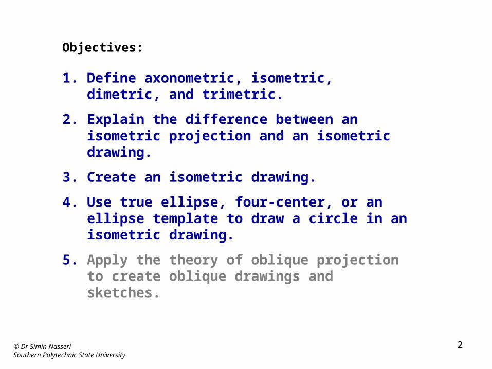
Objectives:
1. Define axonometric, isometric, dimetric, and trimetric.
2. Explain the difference between an isometric projection and an isometric drawing.
3. Create an isometric drawing.
4. Use true ellipse, four-center, or an ellipse template to draw a circle in an isometric drawing.
5. Apply the theory of oblique projection to create oblique drawings and sketches.
© Dr Simin NasseriSouthern Polytechnic State University
3
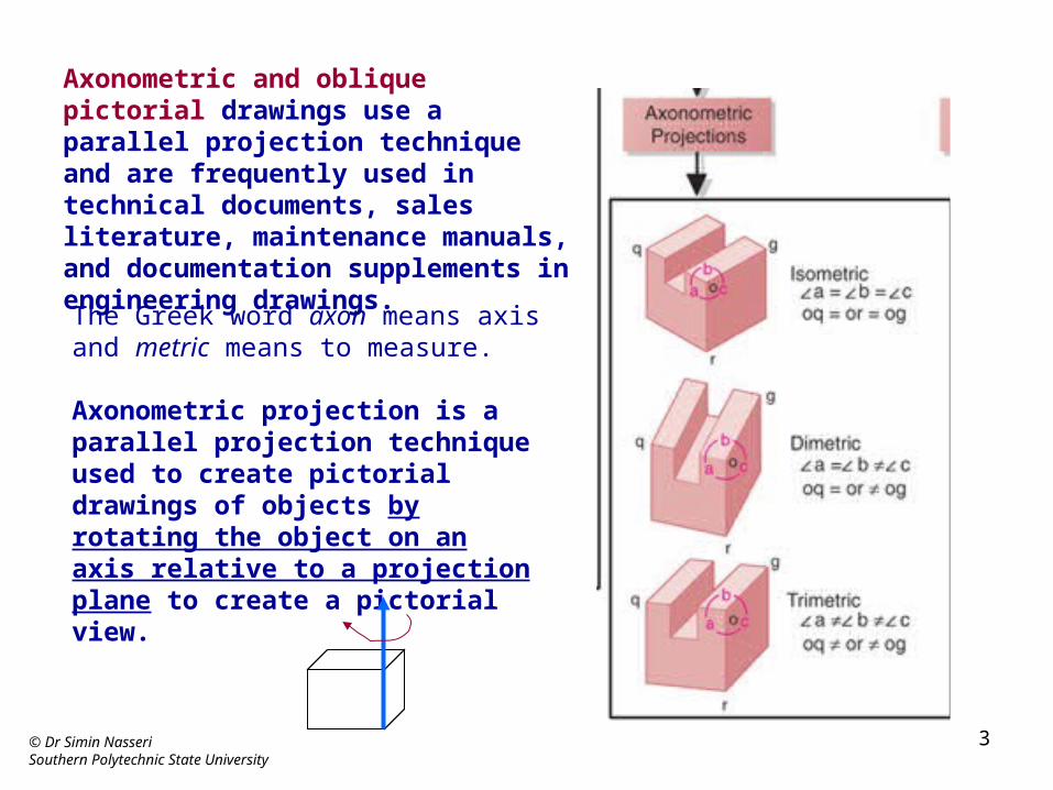
Axonometric and oblique pictorial drawings use a parallel projection technique and are frequently used in technical documents, sales literature, maintenance manuals, and documentation supplements in engineering drawings.
The Greek word axon means axis and metric means to measure.
Axonometric projection is a parallel projection technique used to create pictorial drawings of objects by rotating the object on an axis relative to a projection plane to create a pictorial view.
© Dr Simin NasseriSouthern Polytechnic State University
4
Figure 11.3
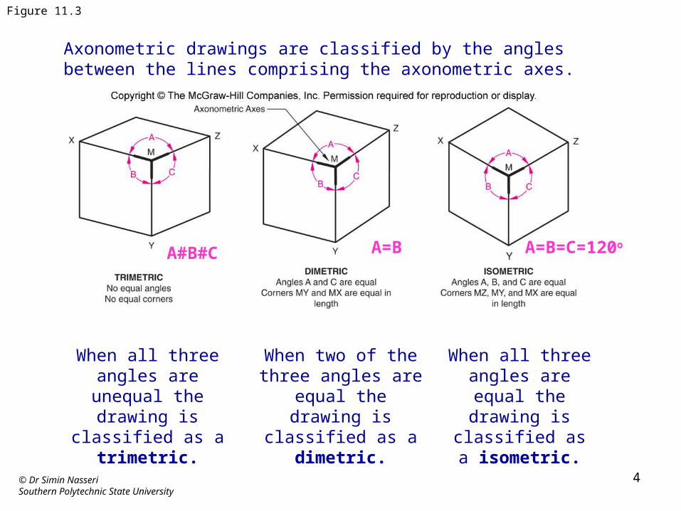
Axonometric drawings are classified by the angles between the lines comprising the axonometric axes.
When all three angles are unequal the drawing is
classified as a trimetric.
When two of the three angles are equal the
drawing is classified as a dimetric.
When all three angles are equal the drawing
is classified as a isometric.
A=B=C=120oA=BA#B#C
© Dr Simin NasseriSouthern Polytechnic State University
5
Figure 11.5
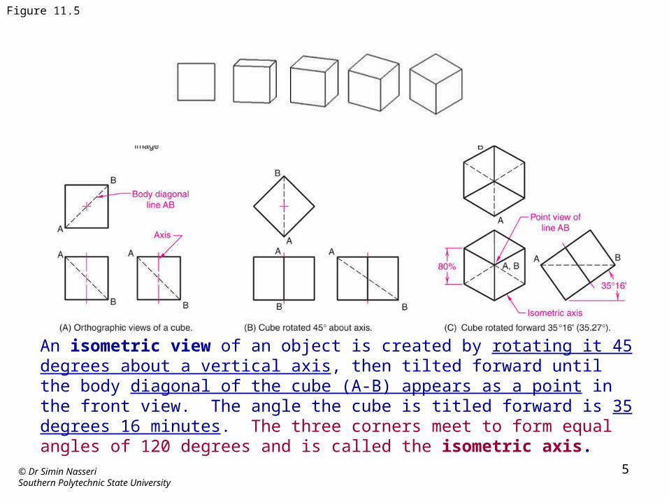
An isometric view of an object is created by rotating it 45 degrees about a vertical axis, then tilted forward until the body diagonal of the cube (A-B) appears as a point in the front view. The angle the cube is titled forward is 35 degrees 16 minutes. The three corners meet to form equal angles of 120 degrees and is called the isometric axis.
© Dr Simin NasseriSouthern Polytechnic State University
6
Figure 11.6
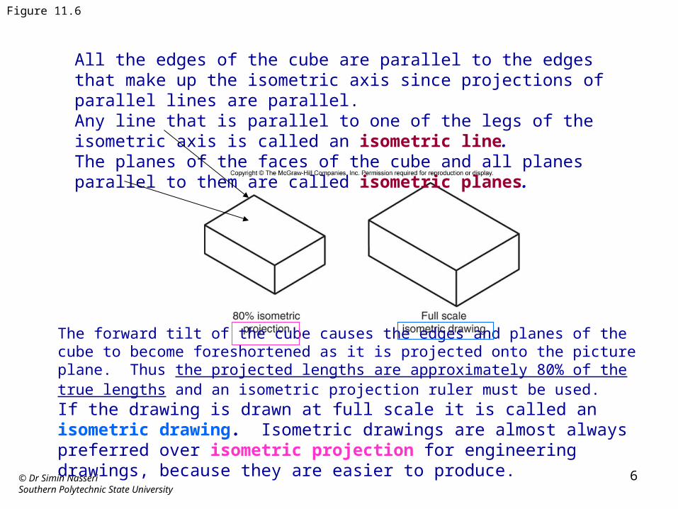
All the edges of the cube are parallel to the edges that make up the isometric axis since projections of parallel lines are parallel. Any line that is parallel to one of the legs of the isometric axis is called an isometric line. The planes of the faces of the cube and all planes parallel to them are called isometric planes.
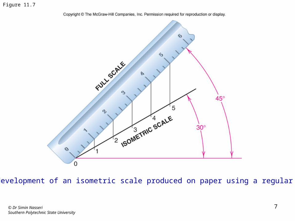
The forward tilt of the cube causes the edges and planes of the cube to become foreshortened as it is projected onto the picture plane. Thus the projected lengths are approximately 80% of the true lengths and an isometric projection ruler must be used. If the drawing is drawn at full scale it is called an isometric drawing. Isometric drawings are almost always preferred over isometric projection for engineering drawings, because they are easier to produce.
© Dr Simin NasseriSouthern Polytechnic State University
7
Figure 11.7
The development of an isometric scale produced on paper using a regular scale.
© Dr Simin NasseriSouthern Polytechnic State University
8
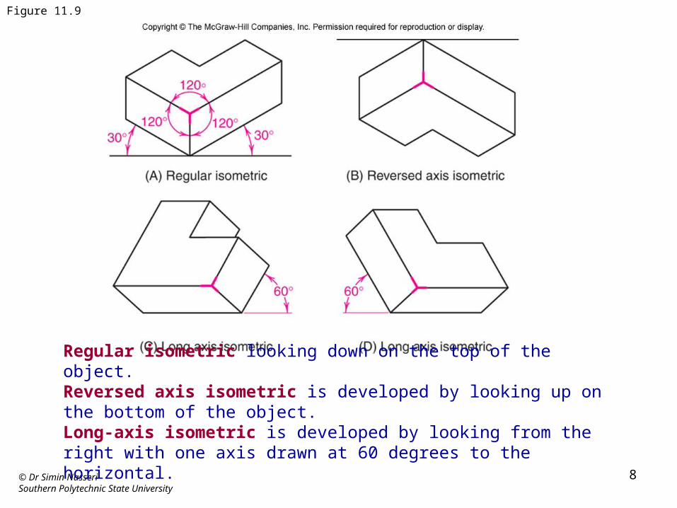
Figure 11.9
Regular isometric looking down on the top of the object.Reversed axis isometric is developed by looking up on the bottom of the object.Long-axis isometric is developed by looking from the right with one axis drawn at 60 degrees to the horizontal.
© Dr Simin NasseriSouthern Polytechnic State University
9
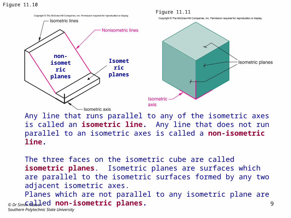
Figure 11.10
Any line that runs parallel to any of the isometric axes is called an isometric line. Any line that does not run parallel to an isometric axes is called a non-isometric line.
The three faces on the isometric cube are called isometric planes. Isometric planes are surfaces which are parallel to the isometric surfaces formed by any two adjacent isometric axes. Planes which are not parallel to any isometric plane are called non-isometric planes.
Figure 11.11
non-isometric
planesIsometric
planes
© Dr Simin NasseriSouthern Polytechnic State University
10
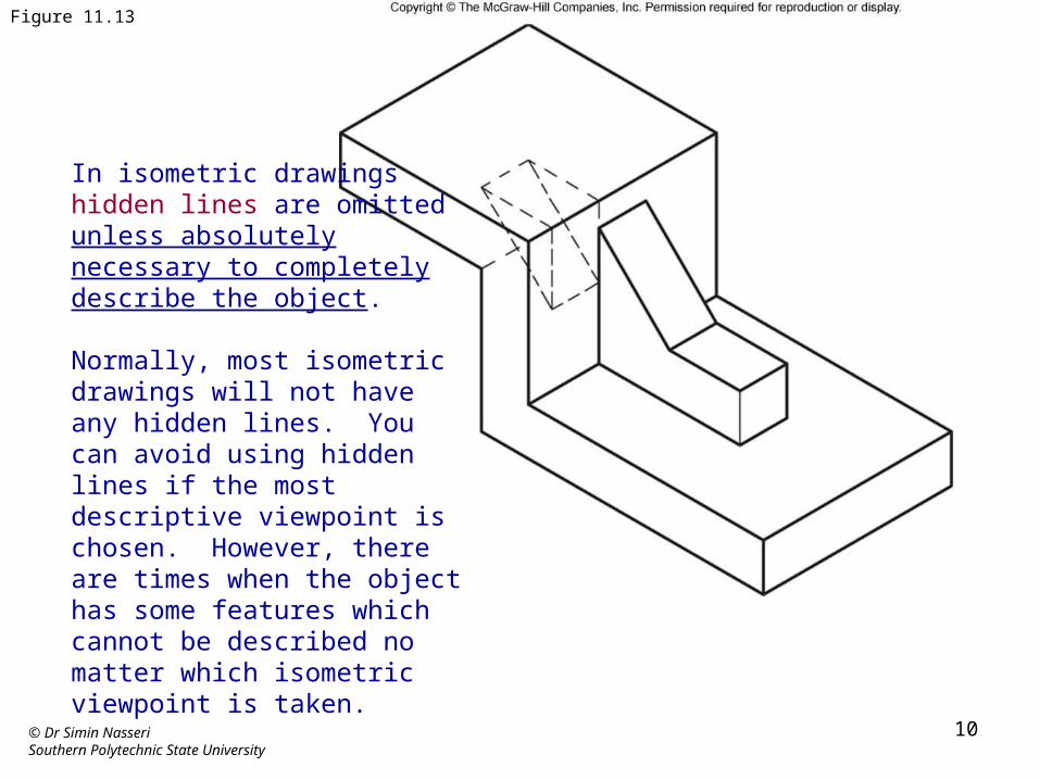
Figure 11.13
In isometric drawings hidden lines are omitted unless absolutely necessary to completely describe the object.
Normally, most isometric drawings will not have any hidden lines. You can avoid using hidden lines if the most descriptive viewpoint is chosen. However, there are times when the object has some features which cannot be described no matter which isometric viewpoint is taken.
© Dr Simin NasseriSouthern Polytechnic State University
11
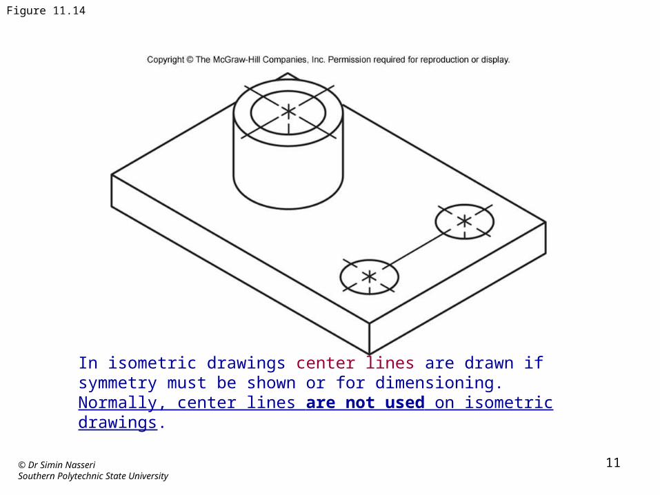
Figure 11.14
In isometric drawings center lines are drawn if symmetry must be shown or for dimensioning. Normally, center lines are not used on isometric drawings.
© Dr Simin NasseriSouthern Polytechnic State University
12
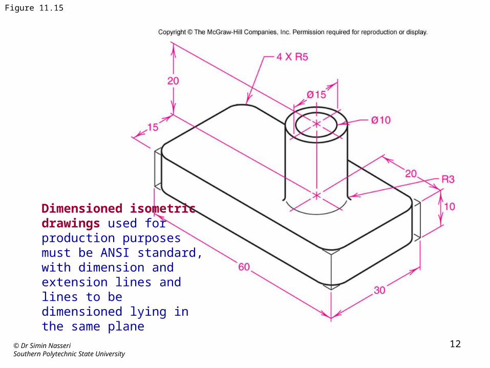
Figure 11.15
Dimensioned isometric drawings used for production purposes must be ANSI standard, with dimension and extension lines and lines to be dimensioned lying in the same plane
© Dr Simin NasseriSouthern Polytechnic State University
13
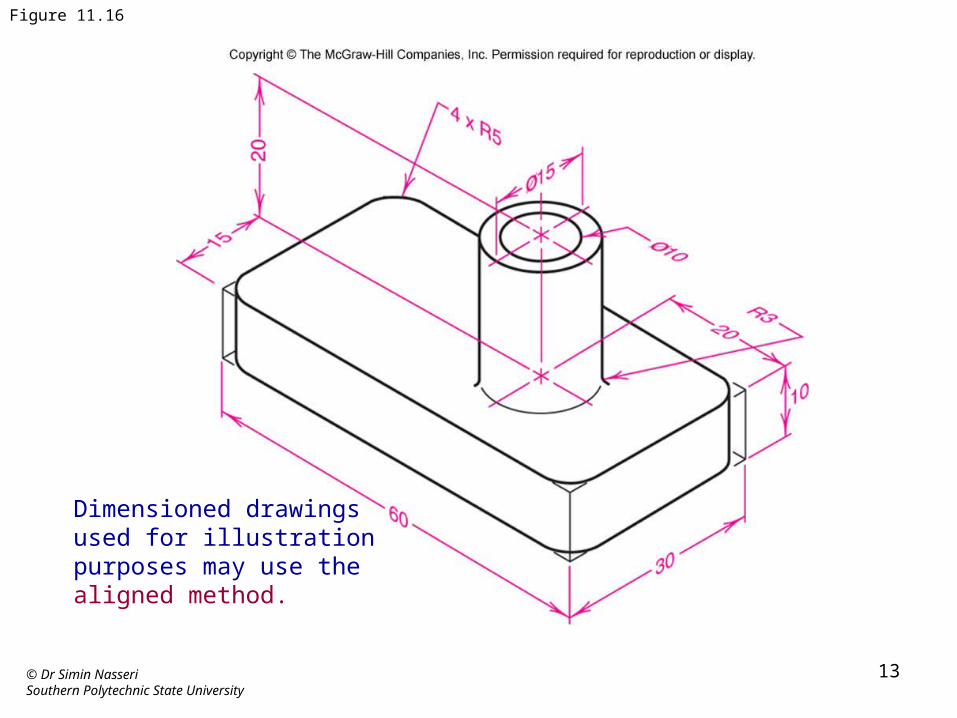
Figure 11.16
Dimensioned drawings used for illustration purposes may use the aligned method.
© Dr Simin NasseriSouthern Polytechnic State University
14
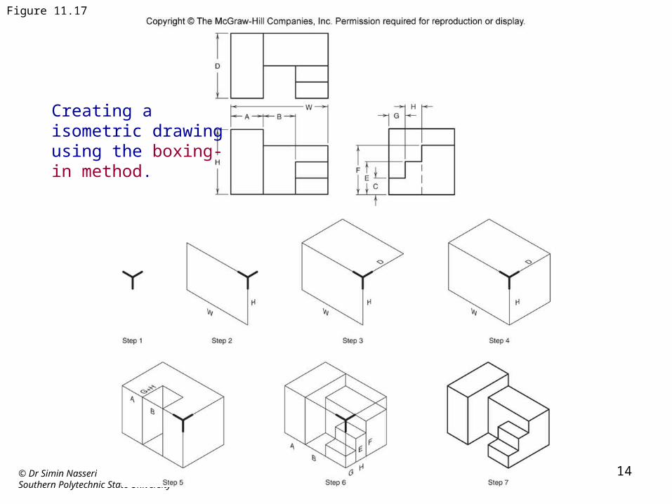
Figure 11.17
Creating a isometric drawing using the boxing-in method.
© Dr Simin NasseriSouthern Polytechnic State University
15
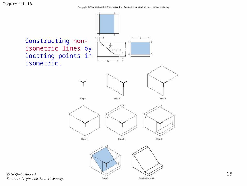
Figure 11.18
Constructing non-isometric lines by locating points in isometric.
© Dr Simin NasseriSouthern Polytechnic State University
16
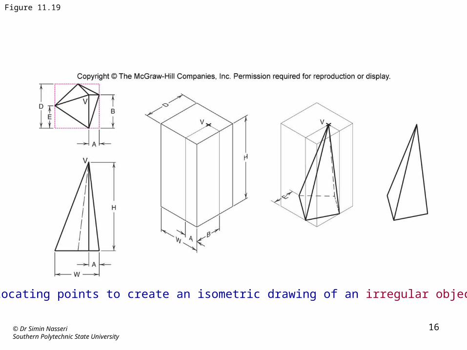
Figure 11.19
Locating points to create an isometric drawing of an irregular object.
© Dr Simin NasseriSouthern Polytechnic State University
17
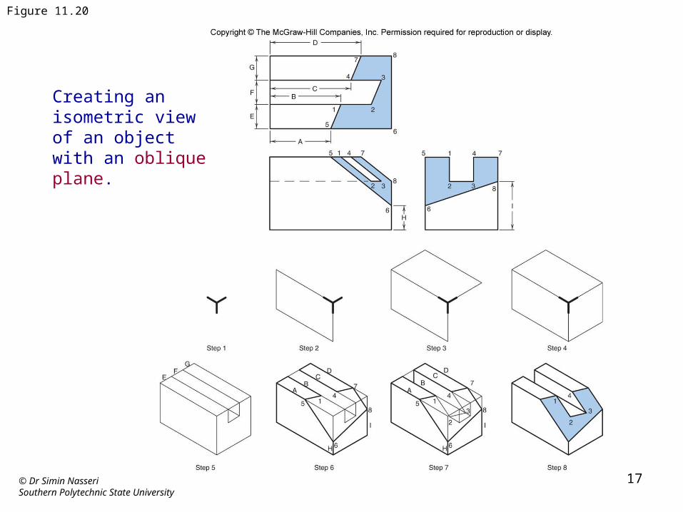
Figure 11.20
Creating an isometric view of an object with an oblique plane.
© Dr Simin NasseriSouthern Polytechnic State University
18
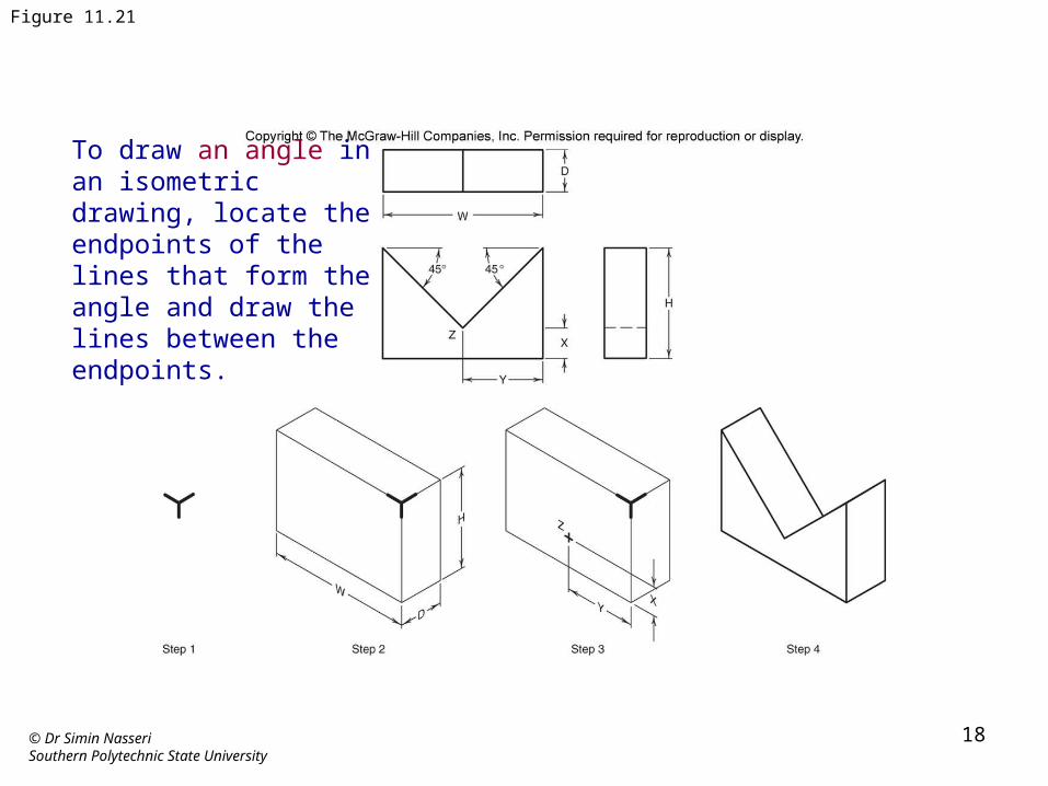
Figure 11.21
To draw an angle in an isometric drawing, locate the endpoints of the lines that form the angle and draw the lines between the endpoints.
© Dr Simin NasseriSouthern Polytechnic State University
19
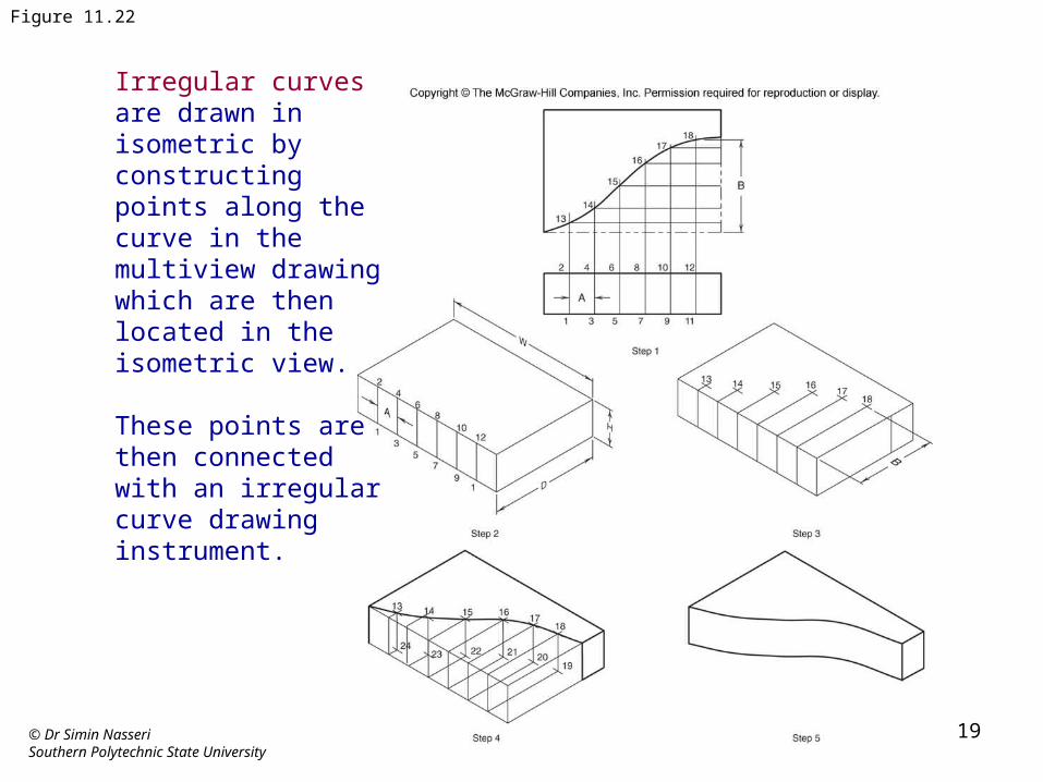
Figure 11.22
Irregular curves are drawn in isometric by constructing points along the curve in the multiview drawing which are then located in the isometric view.
These points are then connected with an irregular curve drawing instrument.
© Dr Simin NasseriSouthern Polytechnic State University
20
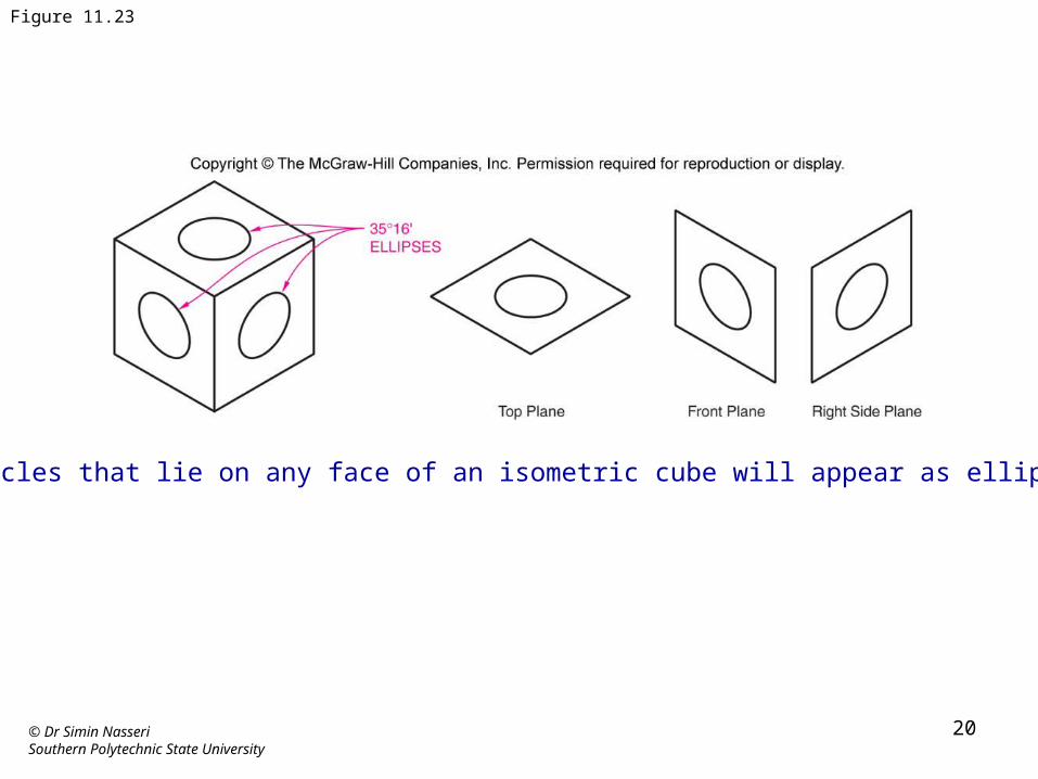
Figure 11.23
Circles that lie on any face of an isometric cube will appear as ellipses.

© Dr Simin NasseriSouthern Polytechnic State University
21
Figure 11.24
The location of center lines and the major and minor axes of isometric ellipses.
© Dr Simin NasseriSouthern Polytechnic State University
22
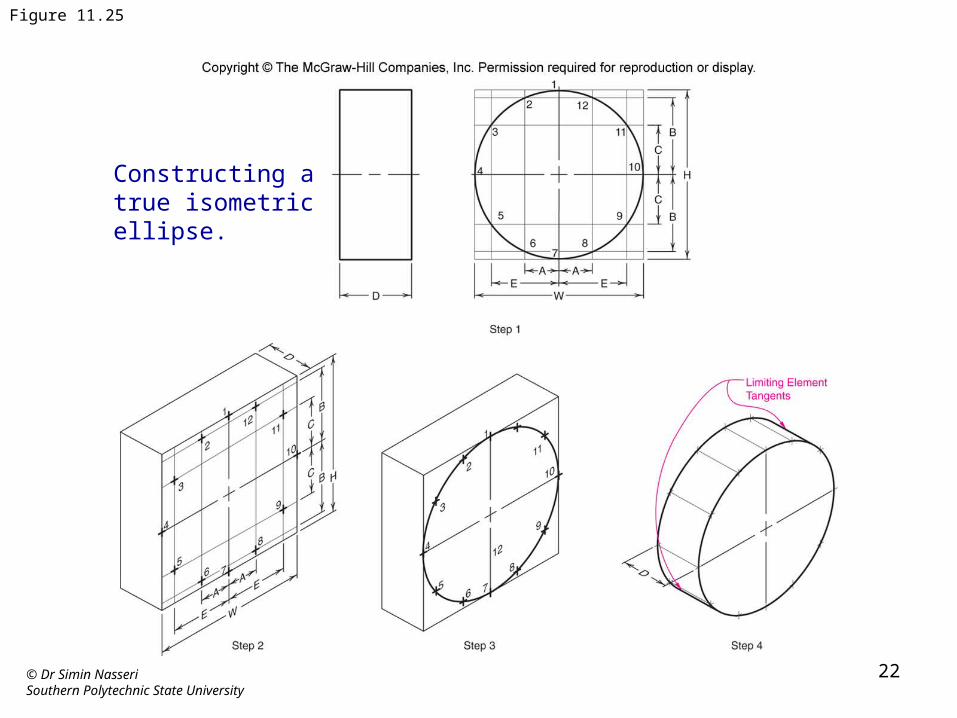
Figure 11.25
Constructing a true isometric ellipse.
© Dr Simin NasseriSouthern Polytechnic State University
23
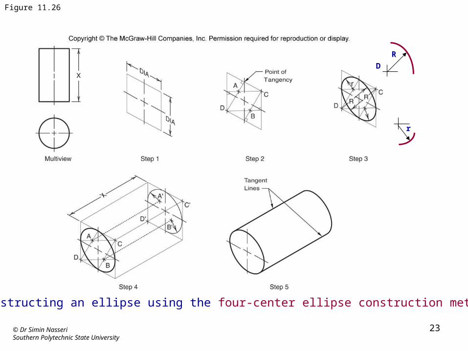
Figure 11.26
Constructing an ellipse using the four-center ellipse construction method.
DR
r
© Dr Simin NasseriSouthern Polytechnic State University
24
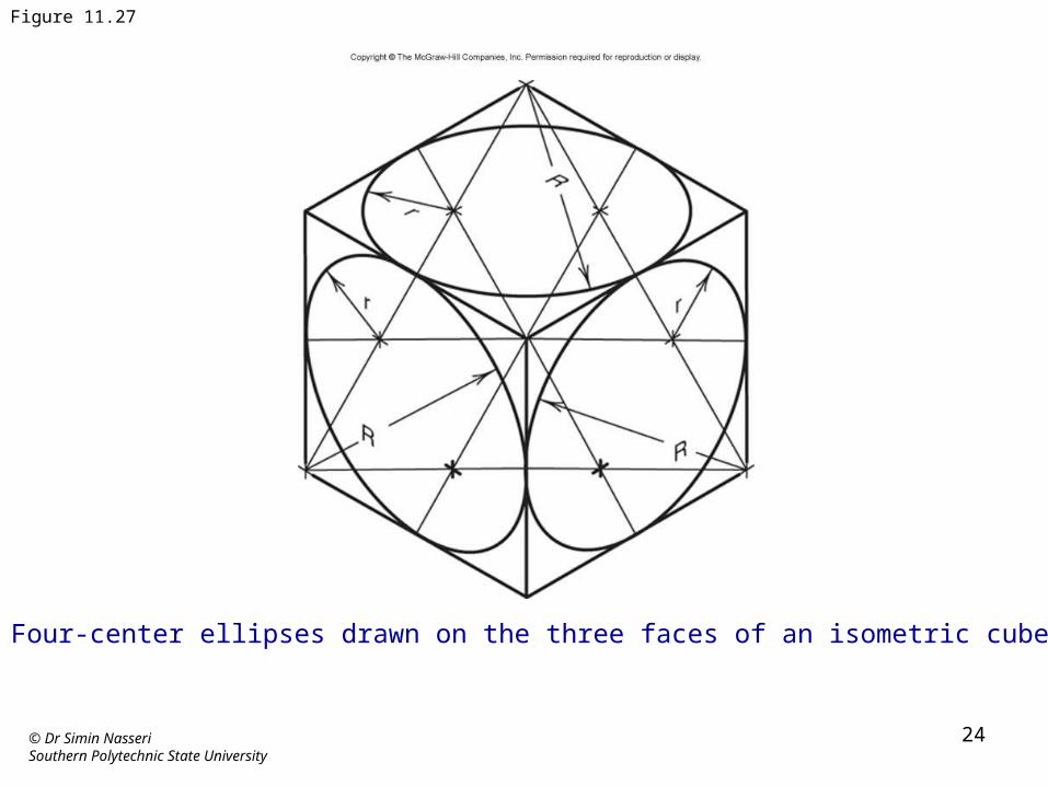
Figure 11.27
Four-center ellipses drawn on the three faces of an isometric cube.
© Dr Simin NasseriSouthern Polytechnic State University
25
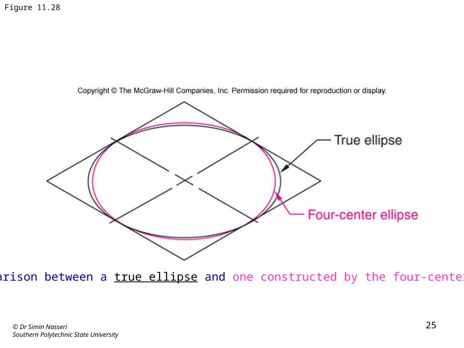
Figure 11.28
The comparison between a true ellipse and one constructed by the four-center method.
© Dr Simin NasseriSouthern Polytechnic State University
26
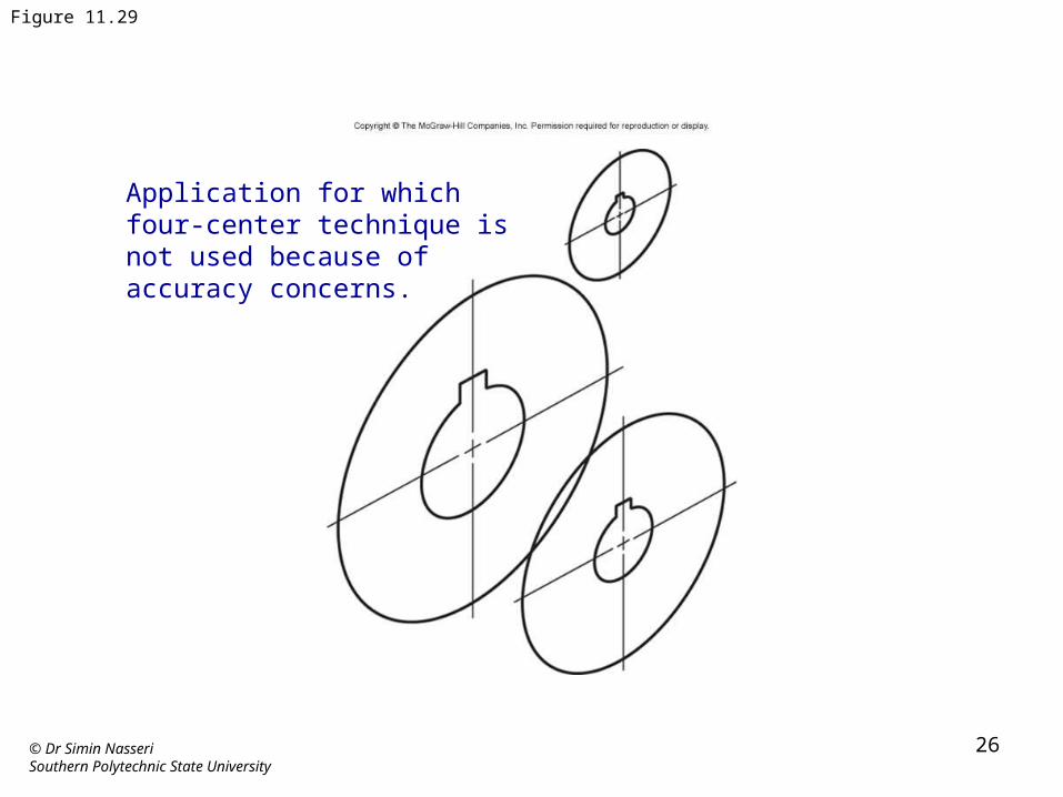
Figure 11.29
Application for which four-center technique is not used because of accuracy concerns.
© Dr Simin NasseriSouthern Polytechnic State University
27
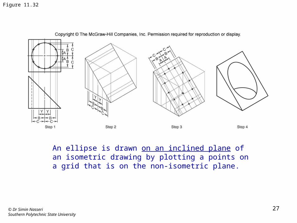
Figure 11.32
An ellipse is drawn on an inclined plane of an isometric drawing by plotting a points on a grid that is on the non-isometric plane.
© Dr Simin NasseriSouthern Polytechnic State University
28
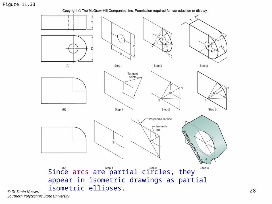
Figure 11.33
Since arcs are partial circles, they appear in isometric drawings as partial isometric ellipses.
© Dr Simin NasseriSouthern Polytechnic State University
29
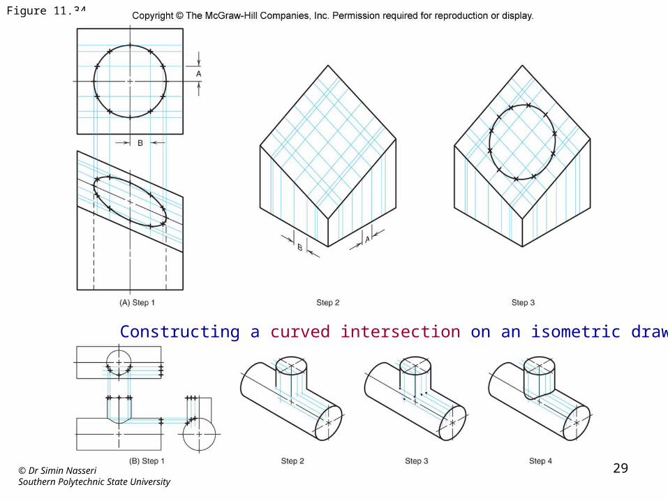
Figure 11.34
Constructing a curved intersection on an isometric drawing.
© Dr Simin NasseriSouthern Polytechnic State University
30
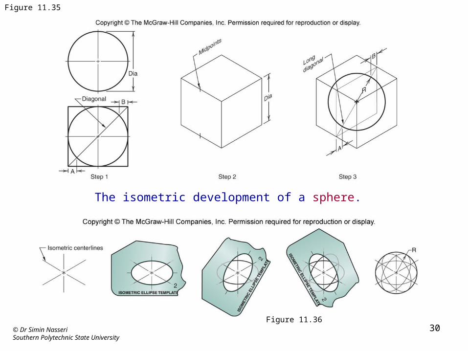
Figure 11.35
The isometric development of a sphere.
Figure 11.36
© Dr Simin NasseriSouthern Polytechnic State University
31
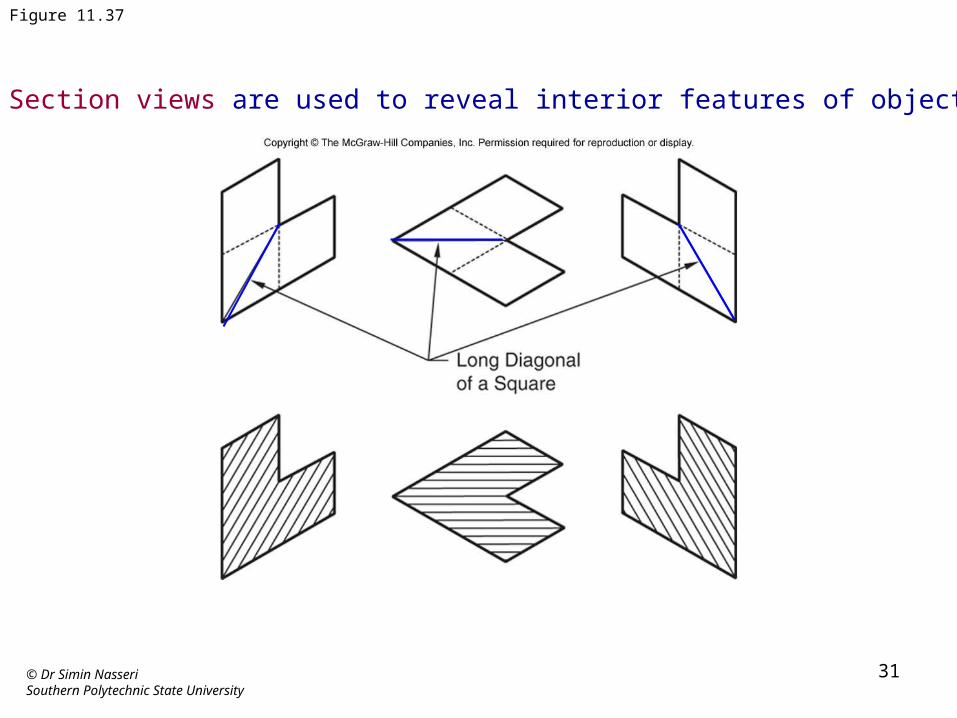
Figure 11.37
Section views are used to reveal interior features of objects.
© Dr Simin NasseriSouthern Polytechnic State University
32
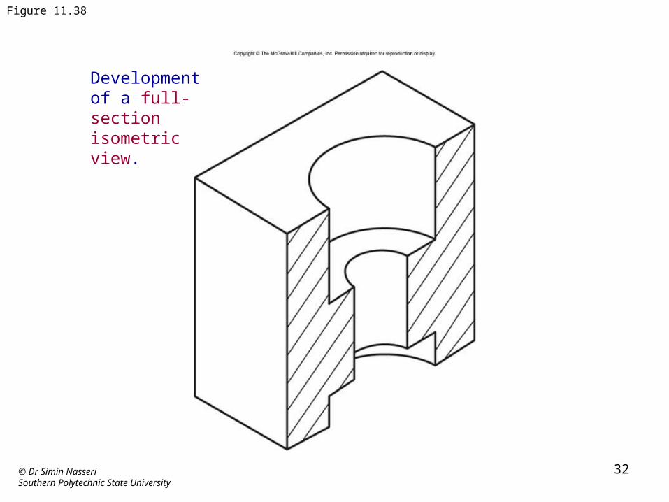
Figure 11.38
Development of a full-section isometric view.
© Dr Simin NasseriSouthern Polytechnic State University
33
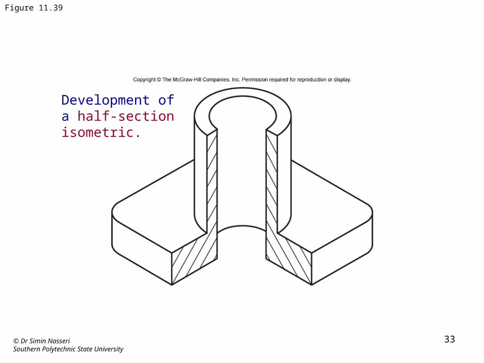
Figure 11.39
Development of a half-section isometric.
© Dr Simin NasseriSouthern Polytechnic State University
34
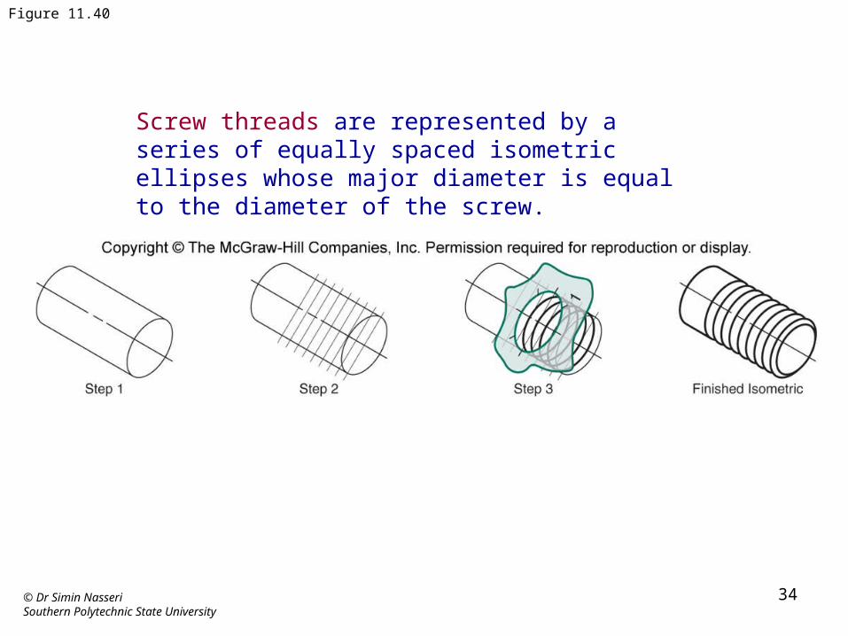
Figure 11.40
Screw threads are represented by a series of equally spaced isometric ellipses whose major diameter is equal to the diameter of the screw.
© Dr Simin NasseriSouthern Polytechnic State University
35
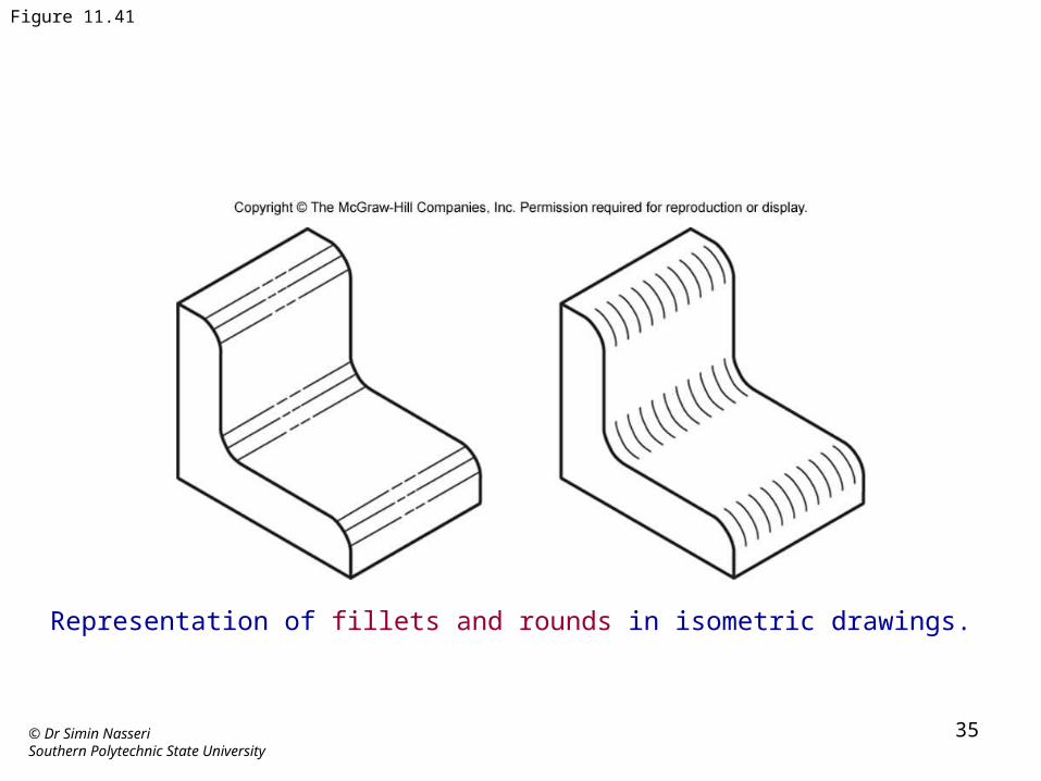
Figure 11.41
Representation of fillets and rounds in isometric drawings.
© Dr Simin NasseriSouthern Polytechnic State University
36
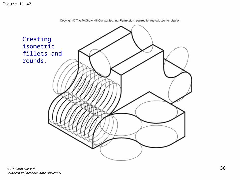
Figure 11.42
Creating isometric fillets and rounds.
© Dr Simin NasseriSouthern Polytechnic State University
37
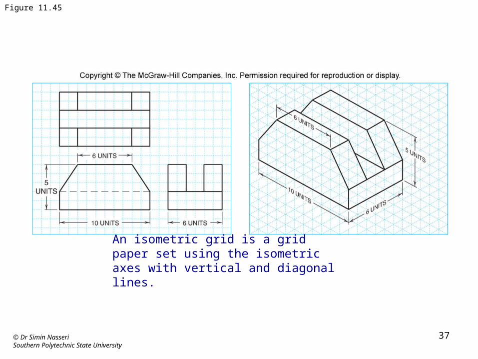
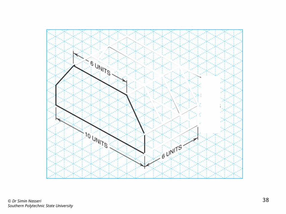
Figure 11.45
An isometric grid is a grid paper set using the isometric axes with vertical and diagonal lines.
© Dr Simin NasseriSouthern Polytechnic State University
38
© Dr Simin NasseriSouthern Polytechnic State University
39
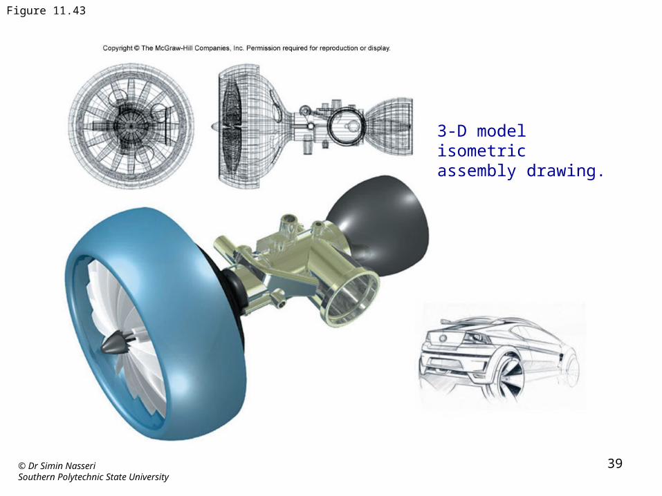
Figure 11.43
3-D model isometric assembly drawing.
© Dr Simin NasseriSouthern Polytechnic State University
40
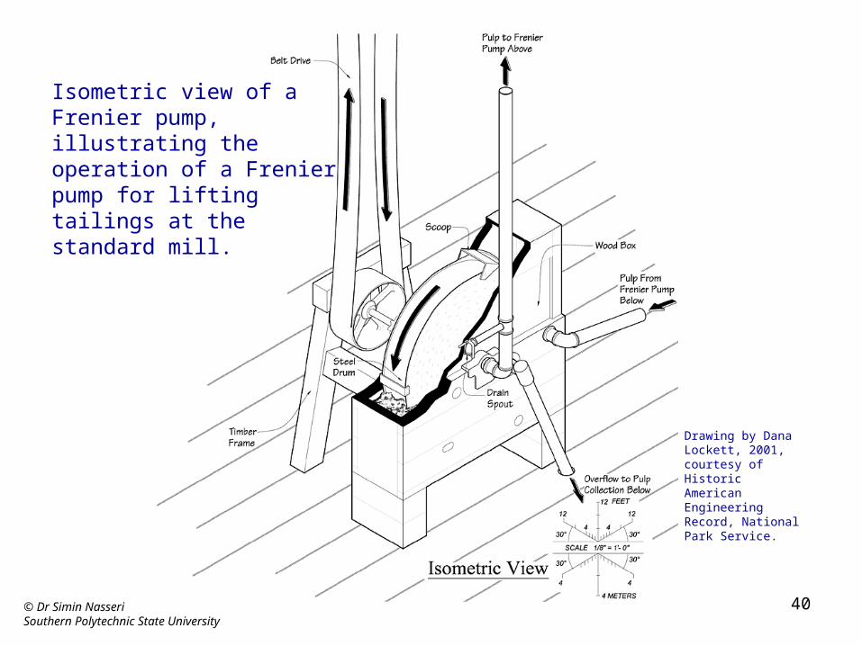
Isometric view of a Frenier pump, illustrating the operation of a Frenier pump for lifting tailings at the standard mill.
Drawing by Dana Lockett, 2001, courtesy of Historic American Engineering Record, National Park Service.
© Dr Simin NasseriSouthern Polytechnic State University
41
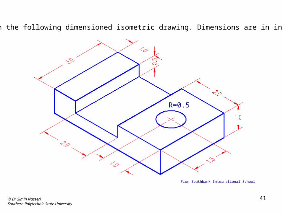
From Southbank International School
Sketch the following dimensioned isometric drawing. Dimensions are in inches.
R=0.5
© Dr Simin NasseriSouthern Polytechnic State University
42
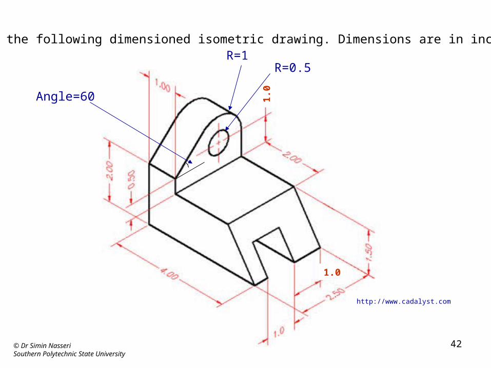
Sketch the following dimensioned isometric drawing. Dimensions are in inches.
http://www.cadalyst.com
1.01.
0
R=1R=0.5
Angle=60
Related Documents