CONTENTS SOLAR PHOTOVOLTAICS CHAPTER 3 by Godfrey Boyle 3.1 INTRODUCTION In Chapter 2 we saw how solar energy can be used to generate electricity by first producing solar heat, preferably at high temperature, to drive a heat engine, which then produces mechanical work to drive an electrical generator. This chapter is concerned with more direct methods of generating electricity from solar radiation. The most important of these is photovoltaics, the conversion of solar energy directly into electricity in a solid-state device. SUMMARY We start with an introductory case study (Section 3.2), then examine the history and basic principles of photovoltaic energy conversion, concentrating initially on monocrystalline silicon devices (Sections 3.3 and 3.4). In Sections 3.5–3.7 we look at various ways of reducing the cost of photovoltaic electricity, including both polycrystalline and ‘thin film’ devices based on silicon or other semiconducting materials, the use of concentrators, and several other innovative concepts. The electrical characteristics of photovoltaic cells and modules are described in Section 3.8, and this is followed by a review of the various current and possible future roles of photovoltaic energy systems, both in supplying power in remote locations (Section 3.9) and in feeding power into local or national electricity grids (Section 3.10). In Sections 3.11 and 3.12 respectively, the economics and the environmental impact of photovoltaic electricity are reviewed, and in Section 3.13 we examine how photovoltaics might be integrated into the electricity supply systems of the UK in the future.

50697697 Solar Advanced
Oct 08, 2014
Welcome message from author
This document is posted to help you gain knowledge. Please leave a comment to let me know what you think about it! Share it to your friends and learn new things together.
Transcript
CONTENTS
SOLARPHOTOVOLTAICS
CHAPTER 3 by Godfrey Boyle
3.1 INTRODUCTIONIn Chapter 2 we saw how solar energy can be used to generate electricityby first producing solar heat, preferably at high temperature, to drive a heatengine, which then produces mechanical work to drive an electricalgenerator.
This chapter is concerned with more direct methods of generatingelectricity from solar radiation. The most important of these isphotovoltaics, the conversion of solar energy directly into electricity in asolid-state device.
SUMMARYWe start with an introductory case study (Section 3.2), then examine thehistory and basic principles of photovoltaic energy conversion,concentrating initially on monocrystalline silicon devices (Sections 3.3and 3.4).In Sections 3.5–3.7 we look at various ways of reducing the cost ofphotovoltaic electricity, including both polycrystalline and ‘thin film’devices based on silicon or other semiconducting materials, the use ofconcentrators, and several other innovative concepts.
The electrical characteristics of photovoltaic cells and modules aredescribed in Section 3.8, and this is followed by a review of the variouscurrent and possible future roles of photovoltaic energy systems, both insupplying power in remote locations (Section 3.9) and in feeding powerinto local or national electricity grids (Section 3.10).
In Sections 3.11 and 3.12 respectively, the economics and theenvironmental impact of photovoltaic electricity are reviewed, and inSection 3.13 we examine how photovoltaics might be integrated into theelectricity supply systems of the UK in the future.

RENEWABLE ENERGY
90
CONTENTS3.2 CASE STUDY: RAPPENECKER HOFRappenecker Hof is a smallmountain inn in the Black Forest,some 15 km from Freiburg insouthern Germany. Since 1987,most of its electricity has beensupplied by an array ofphotovoltaic (PV) solar cellswhich have been integrated intothe south side of the building, aconverted seventeenth-centuryfarmhouse (see Figure 3.1).The inn is situated at an altitudeof 1000 metres, some 5 km fromthe public electricity grid. Sincethe cost of grid connection wasvery high (some DM380 000(£152 000)), it was decided toinstall an independent electricitygenerating system.In such remote locations a dieselgenerator is often used to providepower, but this has somedisadvantages. The diesel engineproduces some pollution andnoise, which can be a problem ina sensitive environment. Also,although the diesel generator hasto be large enough to supply thepeak level of demand from thebuilding, for most of the time it isonly required to supply a smallfraction of the peak demand,which leads to a low overallefficiency of fuel use. Transportingdiesel fuel can also be costly andinconvenient.The photovoltaic solar array usedat Rappenecker Hof consists ofsome 100 photovoltaic modules.
Figure 3.2 shows, in most monthsof the year the PV array providesthe majority of the inn’selectricity requirements. Over the12 months from January toDecember 1988, for example, theinn required some 2780 kWh ofelectricity, of which the PV arrayprovided 77% (2150 kWh) and thediesel generator 23% (650 kWh).The PV array at Rappenecker Hofhas a maximum output, afterallowing for resistive and otherlosses, of some 4 kW in peaksunlight and around 1 kW whenskies are overcast. The array isconnected, via an electronic‘charge controller’, to a lead-acidbattery with a total capacity of 24kilowatt hours (kWh), whichstores the power until it is needed.The battery supplies its power toan inverter, a device whichconverts the direct current (DC)from the battery into alternatingcurrent (AC) conforming to theEuropean standard of 220 volts,50 hertz (see Figure 3.3). Thisallows conventional electricalappliances to be used in the inn.These include a dishwasher,washing machine, refrigerator,iron, TV, radio and compactfluorescent lighting.
Each module, manufactured by theGerman company AEG, is about0.4 m2 in area and contains 40individual photovoltaic cells, eachconsisting of a thin square wafer ofsilicon measuring approximately100 mm by 100 mm.Each cell produces a currentproportional to the intensity of solarradiation falling on it, up to amaximum of just over 2.5 amps, atan electrical potential of around0.5 volts. Each cell thus produces upto about 1.25 watts of power, andsince there are 40 cells, this enablesthe module to produce a peak overallpower of around 50 watts. Inphotovoltaic terminology, suchmodules are therefore rated as havingan output power of 50 watts peak(50 W(p)).The actual power produced by eachmodule only reaches 50 watts whenthe sunlight intensity peaks at1000 watts per square metre, a levelreached at noon on a cloudlesssummer day.There are occasions, for example on asuccession of dull winter days, whenthe PV array does not produceenough energy to meet the demandsof the residents. At such times, astandby diesel generator is used tokeep the batteries charged. But, as
solar contribution diesel generator contribution
ene
rgy/
kWh
0
300
50
250
200
150
100
Jan Feb Mar Apr May Jun Jul Aug Sep Oct Nov Dec1988
Figure 3.1 Rappenecker Hof: amountain inn in the Black Forest.More than three-quarters of itselectricity is supplied by an array ofphotovoltaic cells on the side of thebuilding
Figure 3.2 Monthly contributions from the photovoltaic array and the dieselgenerator to the energy demand of Rappenecker Hof during 1988

CHAPTER 3 SOLAR PHOTOVOLTAICS
91
solar photovoltaic modules
AC to consumers
AC
AC
DC DC
DC
Key AC = alternating currentDC = direct current
back-up diesel generator
charge controller battery inverter
Figure 3.3 The main components of the energy system at Rappenecker Hof
between DM60 000 and DM80 000(£24 000 and £32 000), equivalentto about £6–8 ($9–12) per peakwatt. As they point out, there arean estimated one million housesisolated from the grid in theEuropean Union, and since gridconnection charges for suchhouses can often exceedECU100 000 (£77 000), aphotovoltaic energy system withdiesel backup, like the one atRappenecker Hof, could well be anattractive option. A small 1 kW wind turbine wasadded to the Rappenecker system
in 1990. The PV array stillprovides the majority of the inn’selectricity, with the wind turbinemainly reducing the need to runthe diesel generator in winter.Note: The costs quoted above arebased on 1994 exchange rates, whichwere approximately:£1 = $1.50 = DM2.5 = ECU1.3.These are not the rates that prevailedwhen the system was constructed.(Sources: Schmid et al., 1988 andFraunhofer Institute, 1989 and1991)
The energy system atRappenecker Hof is, however,very expensive. The overallsystem cost, including PV arrays,batteries, inverter, chargecontroller, diesel generator andinstallation charges, wasDM120 000 (about £48 000) – i.e.around £12 per watt of peakcapacity (£12 W(p)–1).But the system designers, at theFraunhofer Institute for SolarEnergy Systems in Freiburg,estimate that after this initialdevelopment phase the overallsystem costs should reduce to

RENEWABLE ENERGY
92
3.3 INTRODUCING PHOTOVOLTAICSIf you were asked to design the ideal energy conversion system, it wouldbe pretty difficult to come up with something better than the solarphotovoltaic (PV) cell.
In the PV cell we have a device which harnesses an energy source thatis by far the most abundant of those available on the planet. As we haveseen, the total annual solar energy input to the earth is more than 15 000times as great as the earth’s current yearly use of fossil and nuclear fuels.
The PV cell itself is, in its most common form, made almost entirelyfrom silicon, the second most abundant element (after oxygen) in theearth’s crust. It has no moving parts and can therefore in principle, if notyet in practice, operate for an indefinite period without wearing out. Andits output is electricity, probably the most useful of all forms of energy.
HISTORICAL BACKGROUNDThe term ‘photovoltaic’ is derived by combining the Greek word for light,photos, with volt, the name of the unit of electromotive force (the forcewhich causes the motion of electrons). The volt was named after the Italianphysicist Count Alessandro Volta, the inventor of the battery. The termphotovoltaic therefore signifies the generation of electricity from light.
The discovery of the photovoltaic effect is generally credited to theFrench physicist, Edmond Becquerel (Figure 3.4), who in 1839 publisheda paper (Becquerel, 1839) describing his experiments with a ‘wet cell’battery, in the course of which he found that the battery voltage increasedwhen its silver plates were exposed to sunlight. (Incidentally, Becquerel’swork on the effects of light on silver compounds laid the foundations formodern photography.)
The first report of the PV effect in a solid substance was made in 1877when two Cambridge scientists, Adams and Day, described in a paper to
Figure 3.6 Bell Laboratories’pioneering PV researchers Pearson,Chapin and Fuller measure theresponse of an early solar cell to light
Figure 3.4 Edmond Becquerel, whodiscovered the photovoltaic effect

CHAPTER 3 SOLAR PHOTOVOLTAICS
93
the Royal Society the variations they observed in the electrical propertiesof selenium when exposed to light (Adams and Day, 1877). Selenium is anon-metallic element similar to sulphur.
In 1883 Charles Edgar Fritts, a New York electrician, constructed aselenium solar cell that was in some respects similar to the silicon solar cellsof today (Figure 3.5). It consisted of thin wafers of selenium covered withvery thin, semi-transparent gold wires and a protective sheet of glass. Buthis cell was very inefficient. The efficiency of a solar cell is defined as theproportion of the solar radiation falling on its surface that is converted intoelectrical energy. Less than 1% of the solar energy falling on these early cellswas converted to electricity. Nevertheless, selenium cells eventually cameinto widespread use in photographic exposure meters.
The underlying reasons for the inefficiency of these early devices wereonly to become apparent many years later, in the early decades of thetwentieth century, when physicists like Max Planck provided new insightsinto the fundamental properties of materials.
But it was not until the 1950s that the breakthrough occurred that set inmotion the development of modern, high-efficiency solar cells. It tookplace at the Bell Telephone Laboratories (Bell Labs) in New Jersey, USA,where a number of scientists, including Darryl Chapin, Calvin Fuller andGerald Pearson (Figure 3.6), were researching the effects of light onsemiconductors.
Semiconductors are non-metallic materials, such as germanium andsilicon, whose electrical characteristics lie between those of conductors,which offer little resistance to the flow of electric current, and insulators,which block the flow of current almost completely. Hence the termsemiconductor.
A few years before, in 1948, two other Bell Labs researchers, Bardeen andBrattain, had produced another revolutionary device using semiconductors– the transistor. Transistors are made from semiconductors (usually silicon)
Figure 3.7(b) The first experimentalapplication of a ‘Solar Battery’ by theBell Telephone system was to powerthis rural telephone amplifier(mounted at the top of the pole) atAmericus, Georgia, in the 1950s
Figure 3.7(a) A promotional demonstration of the Bell Solar Battery powering atelephone system at Bell Labs in the mid-1950s
Figure 3.5 Diagram from CharlesEdgar Fritts’ 1884 US patentapplication for a solar cell

RENEWABLE ENERGY
94
in extremely pure crystalline form, into which tiny quantities of carefullyselected impurities, such as boron or phosphorus, have been deliberatelydiffused. This process, known as ‘doping’, dramatically alters the electricalbehaviour of the semiconductor in a very useful manner that will bedescribed in detail later.
In 1953 the Chapin-Fuller-Pearson team, building on earlier Bell Labsresearch on the PV effect in silicon (Ohl, 1941), produced ‘doped’ siliconslices that were much more efficient than earlier devices in producingelectricity from light.
By the following year they had produced a paper on their work (Chapin,Fuller and Pearson, 1954) and had succeeded in increasing the conversionefficiency of their silicon solar cell to 6%. Bell Labs went on to demonstratethe practical use of solar cells for powering a rural telephone amplifier in themid-1950s, but at that time they were too expensive to be an economicsource of power in most applications (Figures 3.7(a) and 3.7(b)).
In 1958, however, solar cells were used to power a small radio transmitterin the second US space satellite, Vanguard I. Following this first successfuldemonstration, the use of PV as a power source for spacecraft has becomealmost universal (Figure 3.8).
Rapid progress in increasing the efficiency of PV cells, and reducing theircost and weight, has been made over the past few decades by the aerospaceand electronics industries. Their terrestrial uses are now widespread,particularly in providing power for telecommunications, lighting andother electrical appliances in locations where a more conventional electricitysupply would be too expensive. PV cells are also, of course, widely used inconsumer products such as watches and calculators.
A number of PV power stations connected to utility grids are now inoperation in the USA, Germany, Italy, Switzerland and Japan. And a small
Figure 3.8 Arrays of PV cells provideelectrical power for most spacecraft,including the Hubble Space Telescope
CHAPTER 3 SOLAR PHOTOVOLTAICS
95
but increasing number of domestic, commercial and industrial buildingsnow have PV arrays providing a substantial proportion of their energyneeds.
The efficiency of the best silicon solar cells has now reached 24% inlaboratory test conditions (see Box 3.1), and the best silicon PV modulesnow available commercially have an overall efficiency of about 16%.Experience in the PV industry suggests that it takes around 10 years for theefficiencies demonstrated in the laboratory to be achieved by PV productson the market, so it is expected that by the early twenty-first centurymodules will be available with efficiencies of 20% or more.
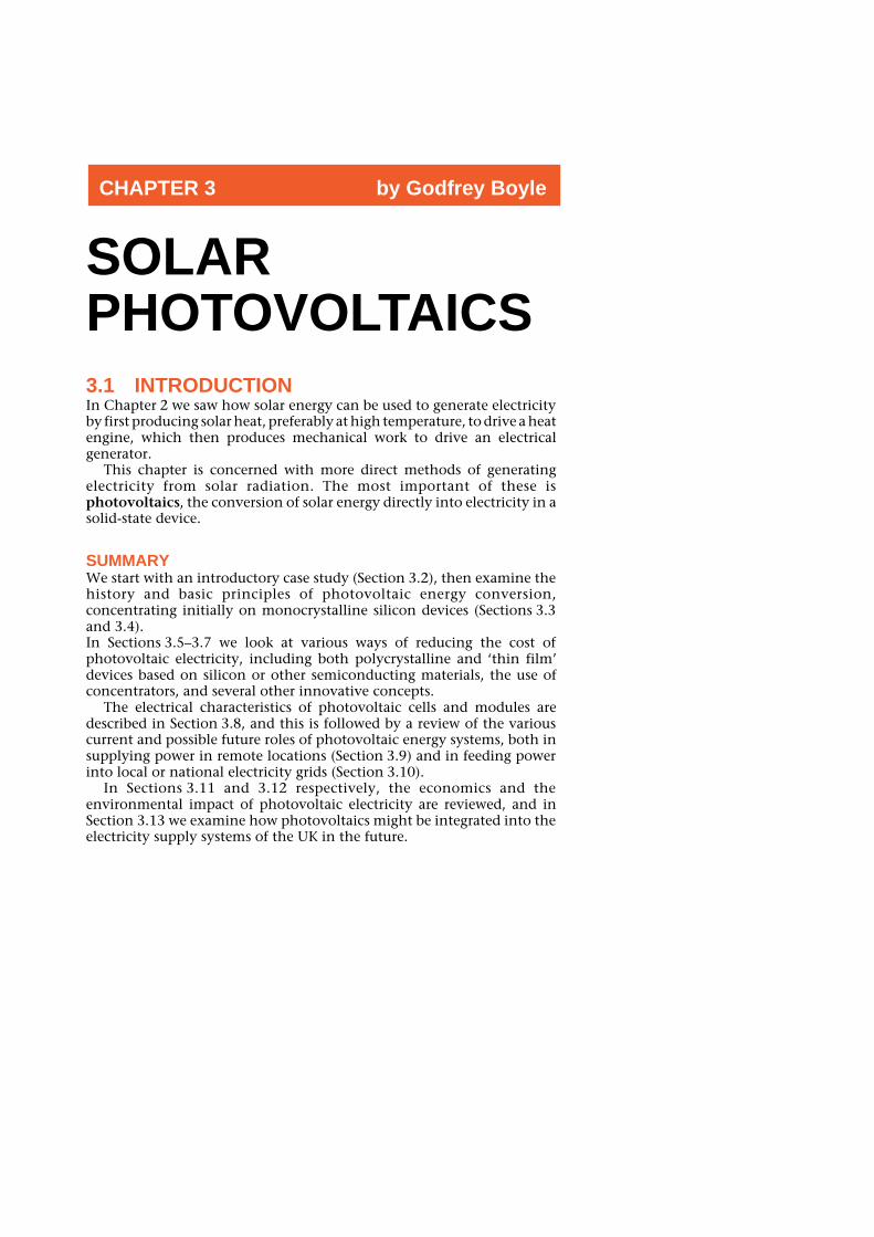
As efficiencies have risen, module prices have fallen, to around $4 perpeak watt (1992 prices) if purchased in large quantities. In 1959, the cost ofPV cells for spacecraft was reportedly some $200 000 per peak watt(Chalmers, 1976). Although PV modules for spacecraft are more expensivethan those for terrestrial use, it is clear that there has been a dramaticreduction in cost in just over 30 years. Figure 3.11 shows how PV productionvolumes and module efficiencies have increased, while module costs havedropped by a factor of around five, since the 1970s. Moreover, as we shallsee, improvements in the cost-effectiveness of PV are likely to continue.
mod
ule
pric
e/$
Wp–1
price efficiency
8
20
10
18
16
14
12
0
year
over
all e
ffici
ency
/%
1978 1980 1982 1984 1986 1988 1990 1992
price efficiency
PV
pro
duct
ion/
MW
p ye
ar–1
70
10
60
50
40
30
20
1976 1978 1980 1982 1984 1986 1988 1990 1992(a)
0
year
30
5
10
35
20
15
(b)
Figure 3.11 (a) PV module productionsince 1976; (b) Increases in PVmodule efficiencies, and decreases incost per peak watt, 1978–92 (Source:Derrick, 1993)
RENEWABLE ENERGY
96
There is widespread internationalagreement that the performance ofPV cells and modules should bemeasured under a set of standardtest conditions.
Essentially, these specify that thetemperature of the cell or moduleshould be 25 °C and that the solarradiation incident on the cellshould have a total power densityof 1000 watts per square metre,with a spectral power distributionknown as Air Mass 1.5.
The spectral power distribution is agraph describing the way in whichthe power contained in the solarradiation varies across the spectrumof wavelengths.
The concept of ‘Air Mass’ relates tothe way in which the spectralpower distribution of radiationfrom the sun is affected by thedistance the sun’s rays have totravel though the atmospherebefore reaching a PV module orarray.
In space, solar radiation isobviously unaffected by the earth’satmosphere and has a powerdensity of approximately1365 watts per square metre. Thecharacteristic spectral powerdistribution of solar radiation asmeasured in space is described asthe Air Mass 0 distribution.
At the earth’s surface, the variousgases of which the atmosphere iscomposed (oxygen, ozone, watervapour, carbon dioxide, etc.)attenuate the solar radiationselectively at different wavelengths.This attenuation increases as thedistance which the sun’s rays haveto travel through the atmosphereincreases.
When the sun is at its zenith (i.e.directly overhead), the distancewhich the sun’s rays have to travelthrough the atmosphere to anobserver (or a PV array) is clearly ata minimum. The characteristicspectral power distribution of solarradiation that is observed underthese conditions is known as theAir Mass 1 distribution.
BOX 3.1: STANDARD TEST CONDITIONS FOR PV CELLS AND MODULES
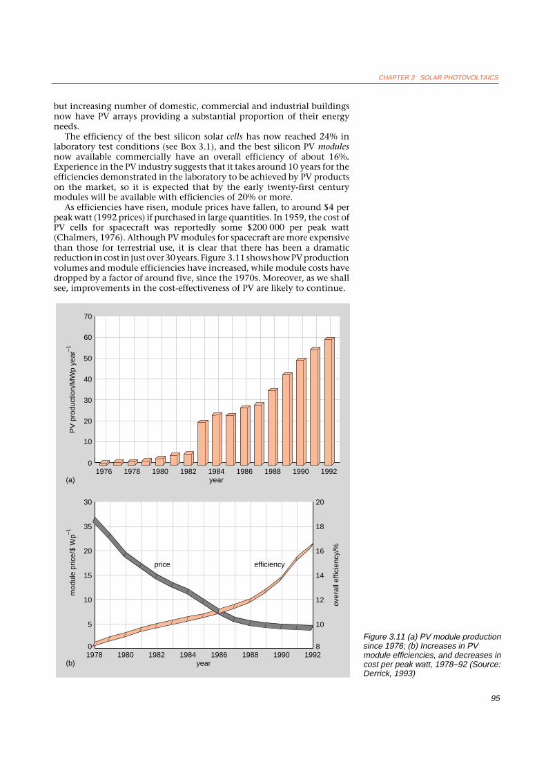
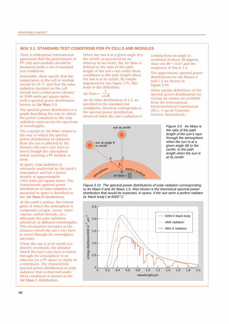
When the sun is at a given angle θ tothe zenith (as perceived by anobserver at sea level), the Air Mass isdefined as the ratio of the pathlength of the sun’s rays under theseconditions to the path length whenthe sun is at its zenith. By simpletrigonometry (see Figure 3.9), thisleads to the definition:
Air Mass ≈
An Air Mass distribution of 1.5, asspecified in the standard testconditions, therefore corresponds tothe spectral power distributionobserved when the sun’s radiation is
coming from an angle tooverhead of about 48 degrees,since cos 48° = 0.67 and thereciprocal of this is 1.5.
The approximate spectral powerdistributions for Air Masses 0and 1.5 are shown inFigure 3.10.
(More precise definitions of thespectral power distributions forvarious air masses are availablefrom the InternationalElectrotechnical Commission(IEC), 3 rue de Varembe,Geneva, Switzerland.)
ener
gy d
istr
ibut
ion/
kW m
–2 µm
–1
0
2.5
2.01.81.61.41.21.00.80.40.20 0.6
2.0
1.5
1.0
0.5
6000 K black body
AM0 radiation
AM1.5 radiation
wavelength/µm
Figure 3.10 The spectral power distributions of solar radiation correspondingto Air Mass 0 and Air Mass 1.5. Also shown is the theoretical spectral powerdistribution that would be expected, in space, if the sun were a perfect radiator(a ‘black body’) at 6000 °C
1cosθ
sun at zenith
S
θ
O
Z
sun at angle θ to zenith
atmosphere
Air Mass = SOZO
earth’s surface
Figure 3.9 Air Mass isthe ratio of the pathlength of the sun’s raysthrough the atmospherewhen the sun is at agiven angle (θ) to thezenith, to the pathlength when the sun isat its zenith

CHAPTER 3 SOLAR PHOTOVOLTAICS
97
3.4 PV IN SILICON: BASIC PRINCIPLESSEMICONDUCTORS AND ‘DOPING’PV cells consist, in essence, of a junction between two thin layers ofdissimilar semiconducting materials, known respectively as ‘p’ (positive)-type semiconductor, and ‘n’ (negative)-type semiconductor. Thesesemiconductors are usually made from silicon, so for simplicity we shallconsider only silicon-based semiconductors here – although, as we shallsee, PV cells can be made from other materials.
n-type semiconductors are made from crystalline silicon that has been‘doped’ with tiny quantities of an impurity (usually phosphorus) in sucha way that the doped material possesses a surplus of free electrons. Electronsare sub-atomic particles with a negative electrical charge, so silicon dopedin this way is known as an n (negative)-type semiconductor.
p-type semiconductors are also made from crystalline silicon, but aredoped with very small amounts of a different impurity (usually boron)which causes the material to have a deficit of free electrons. These ‘missing’electrons are called holes. Since the absence of a negatively chargedelectron can be considered equivalent to a positively charged particle,silicon doped in this way is known as a p (positive)-type semiconductor(see Figures 3.12(a), (b) and (c)).
(a)
(b)
(c)
Figure 3.12 (a) Crystal of pure siliconhas a cubic structure, shown here intwo dimensions for simplicity. Thesilicon atom has four valenceelectrons. Each atom is firmly held inthe crystal lattice by sharing twoelectrons (black) with each of fourneighbours at equal distances from it.Occasionally thermal vibrations or aphoton of light will spontaneouslyprovide enough energy to promote oneof the electrons into the energy levelknown as the conduction band, wherethe electron (colour) is free to travelthrough the crystal and conductelectricity. When the electron movesfrom its bonding site, it leaves a ‘hole’(white), a local region of net positivecharge
(b) Crystal of n-type silicon can becreated by doping the silicon with traceamounts of phosphorus. Eachphosphorus atom (light colour) has fivevalence electrons, so that not all ofthem are taken up in the crystal lattice.Hence n-type crystal has an excess offree electrons (colour)
(c) Crystal of p-type silicon can becreated by doping the silicon with traceamounts of boron. Each boron atom(dark colour) has only three valenceelectrons, so that it shares twoelectrons with three of its siliconneighbours and one electron with thefourth. Hence the p-type crystalcontains more holes than conductionelectrons (Source: Scientific American,1976)

RENEWABLE ENERGY
98
THE P–N JUNCTIONWe can create what is known as a p–n junction by joining these dissimilarsemiconductors. This sets up an electric field in the region of the junction.This electric field is like the electrostatic field you can generate by rubbinga plastic comb against a sweater. It will cause negatively charged particlesto move in one direction, and positively charged particles to move in theopposite direction. (It is worth noting, however, that a p–n junction is nota simple mechanical junction: in practice, the characteristics change from‘p’ to ‘n’ gradually across the junction, and not abruptly.)
THE PV EFFECTWhat happens when light falls on the p–n junction at the heart of a solarcell?
Light can be considered to consist of a stream of tiny particles of energy,called photons. When photons from light of a suitable wavelength fallwithin the p–n junction, they can transfer their energy to some of theelectrons in the material, so ‘promoting’ them to a higher energy level.Normally, these electrons help to hold the material together by forming so-called ‘valence’ bonds with adjoining atoms, and cannot move. In their‘excited’ state, however, the electrons become free to conduct electriccurrent by moving through the material. In addition, when electrons movethey leave behind holes in the material, which can also move (Figures 3.12and 3.13).
This process is similar in some ways to the two-storey ‘car park’ shownin Figure 3.14. In its initial state, the ground floor of the car park is full, sothe cars cannot move around. If some of the cars are ‘promoted’ to the firstfloor, however, not only do they now have room to move around, but the‘holes’ they leave behind, on the ground floor, can also move around.
When the p–n junction is formed, some of the electrons in the immediatevicinity of the junction are attracted from the n-side to combine with holeson the nearby p-side. Similarly, holes on the p-side near the junction areattracted to combine with electrons on the nearby n-side.
The net effect of this is to set up around the junction a layer on the n-side that is more positively charged than it would otherwise be, and, on the
Figure 3.13 A silicon solar cell is awafer of p-type silicon with a thinlayer of n-type silicon on one side.When a photon of light with theappropriate amount of energypenetrates the cell near the junctionof the two types of crystal andencounters a silicon atom (a), itdislodges one of the electrons, whichleaves behind a hole. The energyrequired to promote the electron intothe conduction band is known as theband gap. The electron thuspromoted tends to migrate into thelayer of n-type silicon, and the holetends to migrate into the layer of p-type silicon. The electron then travelsto a current collector on the frontsurface of the cell, generates anelectric current in the external circuitand then reappears in the layer of p-type silicon, where it can recombinewith waiting holes. If a photon with anamount of energy greater than theband gap strikes a silicon atom (b), itagain gives rise to an electron–holepair, and the excess energy isconverted into heat. A photon with anamount of energy smaller than theband gap will pass right through thecell (c), so that it gives up virtually noenergy along the way. Moreover,some photons are reflected from thefront surface of the cell even when ithas an antireflection coating (d). Stillother photons are lost because theyare blocked from reaching the crystalby the current collectors that coverpart of the front surface (Source:Scientific American, 1976)
a b cd
current flows in external circuit
front metal contacts
anti-reflection coating
electron-hole pairs formed
rear metal contact ammeter
holes driftto p-region(back contact)
antireflectioncoating
currentcollector
p-typecrystal
n-typecrystal
electrons drift to n-region(front contacts)

CHAPTER 3 SOLAR PHOTOVOLTAICS
99
p-side, a layer that is more negatively charged than it would otherwise be.In effect, this means that a reverse electric field is set up around the junction:negative on the p-side and positive on the n-side. The region around thejunction is also depleted of charge carriers (electrons and holes) and istherefore known as the depletion region.
When an electron in the junction region is stimulated by an incomingphoton to ‘jump’ into the conduction band, it leaves behind a hole in thevalence band. Two charge carriers (an electron–hole pair) are thus generated.Under the influence of the reverse electric field around the junction, theelectrons will tend to move into the n-region and the holes into the p-region.
The process can be envisaged (Figure 3.15), in terms of the energy levelsin the material. The electrons that have been stimulated by incomingphotons to enter the conduction band can be thought of as ‘rollingdownwards’, under the influence of the electric field at the junction, intothe n-region; similarly, the holes can be thought of as ‘floating upwards’,under the influence of the junction field, into the p-region.
The flow of electrons to the n-region is, by definition, an electric current.If there is an external circuit for the current to flow through, the movingelectrons will eventually flow out of the semiconductor via one of themetallic contacts on the top of the cell. The holes, meanwhile, will flow inthe opposite direction through the material until they reach anothermetallic contact on the bottom of the cell, where they are then ‘filled’ byelectrons entering from the other half of the external circuit.
The generation of electrical power requires both voltage and current. Soin order to produce power, the PV cell must generate voltage as well as thecurrent provided by the flow of electrons. This voltage is, in effect, providedby the internal electric field set up at the p–n junction. As we have seen, asingle silicon PV cell typically produces a voltage of about 0.5 V at a currentof up to around 2.5 amperes – that is, a peak power of up to about 1.25 W.(Depending on their detailed design, some PV cells produce more currentor voltage than this, some less.)
MONOCRYSTALLINE SILICON CELLSUntil fairly recently, the majority of solar cells were made from extremelypure monocrystalline silicon (Si) – that is, silicon with a single, continuouscrystal lattice structure (Figure 3.12) having virtually no defects or impurities.Mono-crystalline silicon is usually grown from a small seed crystal that isslowly pulled out of a molten mass of the less pure polycrystalline silicon
Figure 3.14 ‘Car parking’ analogy ofconduction processes in asemiconductor: (a) The ground floor ofthe car park is full: the cars therecannot move around. The first floor isempty. (b) A car is ‘promoted’ to thefirst floor, where it can move aroundfreely. This also allows cars on theground floor to move around (Source:Green, 1982)
(a) (b)

RENEWABLE ENERGY
100
BOX 3.2: BAND GAPS AND EFFICIENCY
According to the quantumtheory of matter, the quantity ofenergy possessed by any givenelectron in a material will liewithin one of several levels or‘bands’. Those electrons thatnormally hold the atoms of thematerial together (by being‘shared’ between adjoiningatoms, as we saw in Figure 3.12)are described by physicists asoccupying the valence band.
As we shall see, some electronsmay in certain circumstancesacquire higher energy, sufficientto enable them to move aroundwithin the material and thus toconduct electricity. They arethen described as being in theconduction band (Figure 3.15).There is a so-called energy gapor band gap between thesebands, the magnitude of whichvaries from material to material,and which is measured using aunit known as the electron volt.
Metals, which conductelectricity well, have manyelectrons in the conductionband. Insulators, which hardlyconduct electricity at all, havevirtually no electrons in theconduction band. Pure (or‘intrinsic’) semiconductors havesome electrons in theconduction band, but not asmany as in a metal. ‘Doping’pure semiconductors with verysmall quantities of certainimpurities can greatly improvetheir conductivity, however.
If a photon incident on a doped,n-type semiconductor in a PVcell is to succeed in transferringits energy to an electron and‘exciting’ it from the valenceband to the conduction band, itmust possess an energy at leastequal to the band gap. Photons
with energy less than the band gapdo not excite valence electrons toenter the conduction band and are‘wasted’. Photons with energiessignificantly greater than the bandgap do succeed in ‘promoting’ anelectron into the conduction band,but any excess energy is dissipatedas heat. This wasted energy is oneof the reasons why PV cells are not100% efficient in converting solarradiation into electricity. (Anotheris that not all photons incident ona cell are absorbed: a smallproportion are reflected.)
Because the energy of a photonis directly proportional to thefrequency of the light associatedwith it, photons associated withshorter wavelengths (i.e. higherfrequencies) of light, near theblue end of the spectrum, have agreater energy than those oflonger wavelength near the redend of the visible spectrum.
The spectral distribution ofsunlight varies considerablyaccording to weather conditionsand the elevation of the sun inthe sky (see Box 3.1). For
Figure 3.15 (a) Energy bands in a normal (‘intrinsic’) semiconductor; (b) Anelectron can be ‘promoted’ to the conduction band when it absorbs energyfrom light (or heat), leaving behind a ‘hole’ in the valence band;
valence band
energylevel
energygap
(a)
incomingenergy
energylevel
electron
hole
(b)
electron
conduction band

CHAPTER 3 SOLAR PHOTOVOLTAICS
101
maximum efficiency ofconversion of light into electricpower, it is clearly important thatthe band gap energy of thematerial used for a PV cell isreasonably well matched to thespectrum of the light incidentupon it. For example, if themajority of the energy in theincoming solar spectrum is in theyellow–green range(corresponding to photons withenergy of around 1.5 electron
volts), then a semiconductor with aband gap of around 1.5 electronvolts will be most efficient. Ingeneral, semiconductor materialswith band gaps between 1.0 and1.5 electron volts are reasonablywell suited to PV use. Silicon has aband gap of 1.1 electron volts.
The maximum theoreticalconversion efficiency attainable in asingle junction silicon PV cell hasbeen calculated to be about 30%, if
full advantage is taken of ‘lighttrapping’ techniques to ensurethat as many of the photons aspossible are usefully absorbed(Green, 1993). However, multi-junction cells have also beendesigned, in which each junctionis tailored to absorbing a particularportion of the incident spectrum.Theoretically, such cells shouldhave a much higher efficiency,possibly as high as 66% for aninfinite number of junctions –though the efficiencies so farachieved by multi-junction cells inpractice have been very muchlower than this (see Section 3.7).
In practice, the highest efficiencyachieved in commerciallyavailable silicon PV modules (asdistinct from individual PV cells) iscurrently around 16%. Theefficiency of PV modules is usuallylower than that achieved by cellsin the laboratory for variousreasons, which include:
• it is difficult to achieve as highan efficiency consistently in mass-produced devices as in one-offlaboratory cells under optimumconditions;
• laboratory cells are not usuallyglazed or encapsulated;
• in a PV module there areusually inactive areas, betweencells (especially if they are circular)and due to the surroundingmodule frames, that decrease theeffective area available to producepower;
• there are small resistive lossesin the wiring between cells and inthe diodes used to protect cellsfrom short circuiting;
• there are losses due tomismatching between cells ofslightly differing electricalcharacteristics connected in series.
Figure 3.15 (c) When the n-type and p-type semiconductors are combinedinto a p–n junction, their different energy bands combine to give a newdistribution, as shown, and a built-in electric field is created; (d) In the p–njunction, photons of light can excite electrons from the valence band to theconduction band. The electrons ‘roll downwards’ to the n-region, and theholes ‘float upwards’ to the p-region
distance from front of cell
depletion region
photon
conduction band
valence bandholes ‘float upwards’
energy gap
photon
energylevel
(d)
energylevel
n(c)
p
n p
electrons ‘roll downwards’
RENEWABLE ENERGY
102
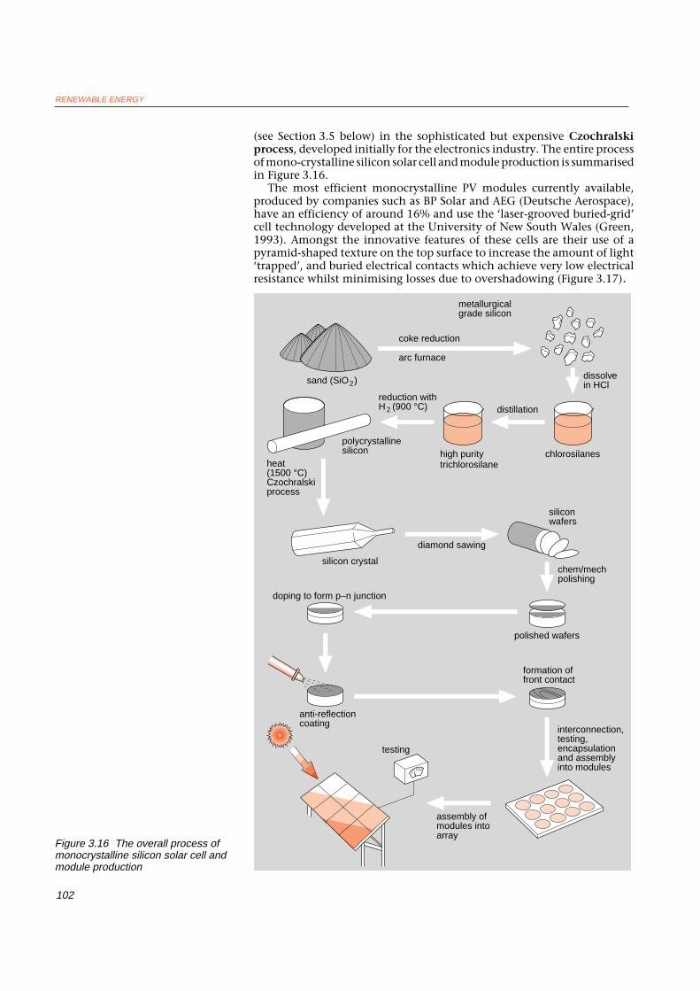
(see Section 3.5 below) in the sophisticated but expensive Czochralskiprocess, developed initially for the electronics industry. The entire processof mono-crystalline silicon solar cell and module production is summarisedin Figure 3.16.
The most efficient monocrystalline PV modules currently available,produced by companies such as BP Solar and AEG (Deutsche Aerospace),have an efficiency of around 16% and use the ‘laser-grooved buried-grid’cell technology developed at the University of New South Wales (Green,1993). Amongst the innovative features of these cells are their use of apyramid-shaped texture on the top surface to increase the amount of light‘trapped’, and buried electrical contacts which achieve very low electricalresistance whilst minimising losses due to overshadowing (Figure 3.17).
Figure 3.16 The overall process ofmonocrystalline silicon solar cell andmodule production
dissolve in HCl
doping to form p–n junction
interconnection, testing, encapsulation and assembly into modules
high puritytrichlorosilane
metallurgicalgrade silicon
distillation
chlorosilanespolycrystallinesilicon
heat(1500 °C)Czochralskiprocess
silicon crystal
diamond sawing
silicon wafers
chem/mechpolishing
formation offront contact
anti-reflectioncoating
assembly of modules into array
sand (SiO2)
2 (900 °C)reduction withH
testing
coke reduction
arc furnace
polished wafers

CHAPTER 3 SOLAR PHOTOVOLTAICS
103
3.5 REDUCING THE COST OF CRYSTALLINEPV CELLSAlthough the latest monocrystalline silicon PV modules are highly efficient,they are also expensive. This is because monocrystalline cells are normallymanufactured by the Czochralski process which is slow, requires highlyskilled operators, and is labour- and energy- intensive. Another major reasonfor their high cost is that until recently almost all such cells were fabricatedfrom extremely pure ‘electronic-grade’ polycrystalline silicon.
However, PV cells can now be made from a less pure, so-called ‘solar-grade’ silicon, with only a small reduction in conversion efficiency. Solar-grade silicon can be manufactured much more cheaply than electronic-gradesilicon, using a number of different low-cost processes.
But a number of more radical approaches to reducing the cost of PV cellsand modules have been under development during the past 20 years or so.These include the growing of silicon in ribbon form, the development ofcells using polycrystalline rather than single-crystal material, the use ofother PV materials such as gallium arsenide, the development of amorphoussilicon and other thin film PV devices, the use of concentrating devices, andvarious other innovative approaches.
SILICON RIBBON CELLSThis approach involves producing a thin ‘ribbon’ of monocrystalline siliconfrom a polycrystalline or single crystal silicon melt. The main process usedis known as ‘edge-defined, film-fed growth’ (EFG), and was developed by theUS firm Mobil Solar. It is described in Figures 3.18 and 3.19. In 1994, Mobil
silicon melt at 1400 °C
nine-sided die
nonagon tube pulled from melt
nonagon tube cut by laser
doping and processing
finished silicon cell
single crystal
1 3
die
die
silicon melt
2
p layer
plated metal front contacts (in laser-cut grooves)
metal back contact
oxide
n+ layer
p+ layer
Figure 3.17 Main features of theadvanced ‘laser-grooved buried-grid’monocrystalline PV cell, as developedat the University of New South Wales,and used in the latest, high-efficiencyPV modules produced by variouscompanies. (The heavily-doped p+ andn+ layers reduce electrical resistance inthe contact areas.)
Figure 3.18 Edge-defined, film-fedgrowth process for PV production,developed by Mobil Solar
Figure 3.19 Thin polygonal tubes ofcrystalline silicon some 4-5 metreslong being ‘grown’ at the Mobil Solarplant in the USA.

RENEWABLE ENERGY
104
Figure 3.20 Polycrystalline siliconconsists of randomly-packed ‘grains’of monocrystalline silicon
sold the technology to Angewandte Solarenergie (ASE) GmbH, a jointventure of two leading German companies active in the PV field, DeutcheAerospace AG (a subsidiary of Daimler-Benz) and NUKEM GmbH, part ofthe RWE consortium which owns Germany’s largest electricity utility.
POLYCRYSTALLINE SILICON CELLSPolycrystalline silicon essentially consists of small grains of mono-crystalline silicon (Figure 3.20). Solar cell wafers can be made directly frompolycrystalline silicon in various ways.
One of the principal technologies involves carefully controlled castingof molten polycrystalline silicon into ingots, as shown in Figure 3.21. Theingots are then cut, using fine wire saws, into thin square wafers andfabricated into complete cells in the same way as monocrystalline cells.
Although polycrystalline PV cells are easier and cheaper to manufacturethan their mono-crystalline counterparts, they tend to be less efficientbecause light-generated charge carriers (i.e. electrons and holes) canrecombine at the boundaries between the grains within polycrystallinesilicon. However, it has been found that by processing the material in sucha way that the grains are relatively large in size, and oriented in a top-to-bottom direction to allow light to penetrate deeply into each grain, theirefficiency can be substantially improved. Commercially availablepolycrystalline PV modules (sometimes called ‘semi-crystalline’ or ‘multi-crystalline’) now have efficiencies of around 10% or more.
An advantage of polycrystalline silicon cells is that they can easily beformed into a square shape, which virtually eliminates any ‘inactive’ areabetween cells – in contrast to the cells produced by the Czochralski processand used in many monocrystalline PV modules, where the circular shapeleads to substantial inactive areas between each adjoining cell. (In somemonocrystalline PV modules, the circular silicon slices are trimmed intosquares, to increase the area of active PV material that can be included ina module of given area.)
POLYCRYSTALLINE THIN FILM SILICON CELLSConventional silicon solar cells need to be several hundred microns thickin order to ensure that most of the photons incident upon them can beabsorbed. But the US firm Astropower Inc. (see Zweibel and Barnett, 1993)has demonstrated that advanced ‘light trapping’ techniques can be used tomaximise the interaction of photons with the material, even in thin layersor ‘films’ of silicon around 20 microns in thickness. These polycrystalline
Figure 3.21 A large polycrystallinesilicon ingot and some silicon wafers

CHAPTER 3 SOLAR PHOTOVOLTAICS
105
thin films, deposited on to ceramic substrates, form the basis of PV cellswith reported efficiencies as high as 15%. The films used in these devices,though thin, are somewhat thicker than in other ‘thin film’ PV cells(see Section 3.6 below), so they are sometimes known as ‘thick film’polycrystalline cells.
The proponents of this approach believe it could soon lead to a newgeneration of PV modules combining the high efficiency and stability ofcrystalline silicon with the low material content and low processing cost ofthin film devices such as amorphous silicon (see Section 3.6 below).
An array of 312 Astropower modules using this technology and deliveringsome 18 kW was installed in 1994 at the PVUSA test site (see Section 3.10below) in Davis, California.
GALLIUM ARSENIDE CELLSSilicon is not the only material suitable for PV. Another is gallium arsenide(GaAs), a so-called compound semiconductor. GaAs has a crystal structuresimilar to that of silicon (see Figure 3.12), but consisting of alternatinggallium and arsenic atoms. In principle it is highly suitable for use in PVapplications because it has a high light absorption coefficient, so only athin layer of material is required. GaAs cells also have a band gap wider thanthat of silicon and close to the theoretical optimum for absorbing theenergy in the terrestrial solar spectrum (see Box 3.2). Cells made from GaAsare therefore very efficient.
They can also operate at relatively high temperatures without theappreciable performance degradation from which silicon and many othersemiconductors suffer. This means that GaAs cells are well suited to use inconcentrating PV systems (see Section 3.7 below).
On the other hand, cells made from GaAs are substantially moreexpensive than silicon cells, partly because the production process is notso well developed, and partly because gallium and arsenic are not abundantmaterials.
GaAs cells have often been used when very high efficiency, regardless ofcost, is required – as in many space applications. This was also the case withthe ‘Sunraycer’ (Figure 3.22a), a photovoltaically-powered electric car
plexiglass coated with gold filmreflects 98 percent of the sun’sinfrared radiation
lights and a fiber-opticrear-view system incorporatedinto the top fins
strong, lightweight shell ofhexcell honeycomb sandwichedbetween kevlar
covered with plastic disks20-inch low-friction bicycle tires
output is 1,550 watts at noon.
8,000 gallium arsenide solar cells and 1,500
maximum available solar power from eacharray to the battery and motor. The total
monocrystalline silicon cells are arranged in20 arrays. Peak power trackers deliver the
Figure 3.22a The ‘Sunraycer’, aphotovoltaically-powered lightweightelectric car using mainly galliumarsenide cells

RENEWABLE ENERGY
106
sponsored by General Motors, which in 1987 won the Pentax World SolarChallenge race for solar-powered vehicles when it travelled the 3000 kmfrom Darwin to Adelaide at an average speed (in day time) of 66 km perhour. The Sunraycer was superior to the other solar cars at the time partlybecause of its ultra-lightweight, low drag design and high efficiency electricdrive system, and partly because most of its PV cells were of the GaAs type,which gave it a speed and range advantage. However, it should be addedthat in the 1990 race the winning car, from the Biel School of Engineeringin Switzerland, used monocrystalline silicon cells. These were of theadvanced, laser-grooved buried-grid type, as described in Figure 3.17 above.The 1993 winner was the ‘Honda Dream’(Figure 3.22b), powered by 20%efficient monocrystalline silicon PV cells, which achieved an average speedof 85 km per hour over the 3000 km course.
3.6 THIN FILM PV
AMORPHOUS SILICONSilicon can not only be formed into the monocrystalline and polycrystallinestructures described above. It can also be made in a less structured formcalled amorphous silicon (a-Si), in which the silicon atoms are much lessordered than in the crystalline form. In a-Si, not every silicon atom is fullybonded to its neighbours, which leaves so-called ‘dangling bonds’ that canabsorb the additional electrons introduced by doping, so rendering any p–n junction ineffective.
However, this problem is largely overcome in the process by which a-Sicells are normally manufactured. A gas containing silicon and hydrogen(such as silane, SiH4), and a small quantity of dopant (such as boron), isdecomposed electrically in such a way that it deposits a thin film ofamorphous silicon on a suitable substrate (backing material) such asstainless steel. The hydrogen in the gas has the effect of providing additionalelectrons which combine with the dangling silicon bonds to form, in effect,an alloy of silicon and hydrogen. The dopant that is also present in the gascan then have its usual effect of contributing charge carriers to enhance theconductivity of the material.
Solar cells using a-Si have a somewhat different form of junction betweenthe p- and the n-type material. A so-called ‘p–i–n’ junction is usuallyformed, consisting of an extremely thin layer of p-type a-Si on top, followed
Figure 3.22b The 1993 World SolarChallenge winner, the ‘Honda Dream’

CHAPTER 3 SOLAR PHOTOVOLTAICS
107
by a thicker ‘intrinsic’ (i) layer made of undoped a-Si, and then a very thinlayer of n-type a-Si. The structure is as shown in Figure 3.23. The operationof the PV effect in a-Si is generally similar to that in crystalline silicon,except that in a-Si the band gap, although wider, is less clearly defined.
Amorphous silicon cells have various advantages and disadvantages.Onthe credit side, a-Si is much cheaper to produce than crystalline silicon. Itis also a much better absorber of light, so much thinner (and therefore
back contact
light
silicon dioxide (SiO2)
p-type
amorphous silicon
intrinsic
n-type
aluminium
top conducting layer
tin oxide (SnO2)
glass
Figure 3.23 Structure of anamorphous silicon cell. The topelectrical contact is made of anelectrically-conducting, buttransparent, layer of tin oxidedeposited on the glass. Silicondioxide forms a thin ‘barrier layer’between the glass and the tin oxide.The bottom contact is made ofaluminium. In between are layers ofp-type, intrinsic and n-typeamorphous silicon
BOX 3.3: THE SUN SEEKER – A PV-POWERED AEROPLANE
One particularly interestingapplication of amorphous siliconPV has been in the construction ofa small photovoltaically-poweredaircraft, the Sun Seeker(Figure 3.24), which in thesummer of 1990 flew 4060 kmacross the United States, setting aworld record for fuel-less flight.
Piloted by her designer EricRaymond, the Sun Seeker took offin California and, after 22overnight stops and some breakson rainy days, landed near KittyHawk, North Carolina, where theWright Brothers made the world’sfirst powered flight in 1903.
Power for the 2.4 metre diameterpropeller on the Sun Seeker camefrom an array of Sanyoamorphous silicon solar cellsstretched across the wings of theplane. Some 700 cells, depositedon a thin film of heat-resistantplastic, generated up to 300 wattsof power to charge a nickel-cadmium battery. The batterypowered a 2.2 kW electric motorto drive the propeller to enablethe plane to take off.
In flight the ultra-light planebehaved as a glider, withoccasional assistance from thepropeller when needed. Theamorphous silicon cells were only0.12 mm thick and flexibleenough to be bent, if necessary,into cylinders only 10 mm indiameter. They generated200 milliwatts of power pergramme of weight, and costaround £5 ($8) per peak watt ofpower.
(Source: based on Piellisch, 1991)
Figure 3.24 The Sun Seeker inflight; and on the ground

RENEWABLE ENERGY
108
cheaper) films can be used. The a-Si manufacturing process operates at amuch lower temperature than that for crystalline silicon, so less energy isrequired; it is suited to continuous production; and it allows quite largeareas of cell to be deposited on to a wide variety of both rigid and flexiblesubstrates, including steel, glass and plastics.
On the debit side, however, a-Si cells are currently much less efficientthan their single-crystal or polycrystalline silicon counterparts: maximumefficiencies achieved with small, single junction cells in the laboratory arecurrently around 12%. Moreover, the efficiency of currently-available a-Simodules degrades, within a few months of exposure to sunlight, from aninitial 6–7% to around 4%.
Strenuous attempts are being made by many manufacturers to improvethe efficiency of a-Si cells, and to solve the degradation problem, but thesedifficulties have not yet been fully overcome. The most promising approachcurrently involves the development of multiple-junction a-Si devices (seeSection 3.7 below), which should result in both reduced degradation andimproved efficiency.
Nevertheless, a-Si cells have already been very successful commercially,as power sources for a wide variety of consumer products such as calculators,where the requirement is not so much for high efficiency as for low cost.
In 1990, amorphous silicon cells accounted for around 30% of totalworldwide PV sales.
Amorphous silicon is by no means the only material suited to thin filmPV, however. Amongst the many other possible thin film technologiessome of the most promising are those based on compound semiconductors,and in particular copper indium diselenide (CuInSe2, usually abbreviatedto CIS) and cadmium telluride (CdTe). Modules based on both technologieshave reached the pilot production stage.
COPPER INDIUM DISELENIDECopper indium diselenide (CIS) is a compound of copper, indium andselenium, which is a semiconductor. Thin film CIS cells have attainedlaboratory efficiencies of 12.5%, whilst pre-production CIS modules30 centimetres square with efficiencies of nearly 10% have been producedby the firm Siemens Solar (Figure 3.25). In 1994, Siemens Solar announcedit would be commercialising its CIS technology in partnership with themajor US manufacturer Corning Glass.
Figure 3.25 (Right) Array of copperindium diselenide (CIS) PV modules;(Below) CIS module side-by-side withcrystalline silicon PV module

CHAPTER 3 SOLAR PHOTOVOLTAICS
109
Figure 3.26 Cadmium telluride PVmodules made by BP Solar
CIS modules with these promisingly high efficiencies do not appear tosuffer from the performance degradation observed in a-Si PV modules.Somewhat thicker films are required than for a-Si, and indium is a relativelyexpensive material, but the quantities required are extremely small.
However, some CIS manufacturing processes involve the use of hydrogenselenide gas, which is highly toxic and could constitute a serious healthhazard in the (extremely unlikely) event of an industrial accident. Theseand other environmental aspects are discussed in Section 3.12.
In 1994 a small US firm, Energy Photovoltaics Inc., of Princeton, NJ,announced it would be manufacturing 50 watt CIS modules of over 8%guaranteed efficiency and selling them at prices below $3 per watt for ordersof 10 kW or more.
CADMIUM TELLURIDEAnother compound semiconductor suitable for thin film PV cells is cadmiumtelluride (CdTe), composed of cadmium and tellurium. BP Solar, a subsidiaryof British Petroleum, is one of a number of companies actively involved inCdTe photovoltaics (see Figure 3.26). One advantage of CdTe modules isthat they can be made using a relatively simple and inexpensiveelectroplating-type process. The band gap of CdTe is close to the optimum,and efficiencies of over 10% are claimed, without the performancedegradation that occurs in a-Si cells.
However, since the modules contain cadmium, a highly toxic substance,stringent precautions need to be taken during the manufacture, use andeventual disposal of CdTe modules. This issue will be discussed in moredetail in Section 3.12.
The US firm Golden Photon Inc., of Golden, Colorado, began productionof 24 watt CdTe modules in 1994. Small-scale CdTe cells are also producedby the Japanese firm Matsushita for use in consumer products.
3.7 OTHER INNOVATIVE PV TECHNOLOGIESMULTI-JUNCTION PV CELLSAn ingenious way of improving the overall conversion efficiency of PV cellsand modules is the ‘stacked’ or multi-junction approach, in which two (ormore) PV junctions, usually of the thin film type, are layered one on top of

RENEWABLE ENERGY
110
the other, each layer extracting energy from a particular portion of thespectrum of the incoming light. (Thin films of different types can also beused.) A cell with two layers is often called a ‘tandem’ device.
The band gap of amorphous silicon, for example, can be increased byalloying the material with carbon, so that the resulting material respondsbetter to light at the blue end of the spectrum. Alloying with germanium,on the other hand, decreases the band gap so the material responds to lightat the red end of the spectrum.
Typically, a wide band gap a-Si junction would be on top, absorbing thehigher-energy light photons at the blue end of the spectrum, followed byother thin film a-Si junctions, each having a band gap designed to absorba portion of the lower light frequencies, nearer the red end of the spectrum(Figure 3.27). In addition to increasing overall efficiency, the multi-junctionarrangement also has the benefit of substantially reducing the degradationin efficiency that occurs with single-junction a-Si cells.
CONCENTRATING PV SYSTEMSAnother way of getting more energy out of a given number of PV cells is touse mirrors or lenses to concentrate the incoming solar radiation on to thecells. (The approach is similar to that described in Section 2.10, on solarthermal engines.) This has the obvious advantage that substantially fewercells are required – to an extent depending on the concentration ratio,which can vary from as little as two to several hundred or even thousandtimes. The concentrating system must have an aperture equal to that of anequivalent flat plate array to collect the same amount of incoming energy.
The systems with the highest concentration ratios use complex (andexpensive) sensors, motors and controls to allow them to track the sun intwo axes (azimuth and elevation), ensuring that the cells always receive themaximum amount of solar radiation. Systems with lower concentrationratios often track the sun only on one axis and can have very simplemechanisms for orienting the array towards the sun.
Most concentrators can only utilise direct solar radiation. This is aproblem in countries like the UK where nearly half the solar radiation isdiffuse. However, some unconventional designs of concentrator, such asthe Winston type (see Section 2.9) do allow some diffuse radiation, as wellas direct radiation, to be concentrated (see also Boes and Luque, 1993).
There is some evidence that the latest designs of concentrating PVsystems (for example, Figure 3.28) may now be more cost-effective thanflat plate, non-concentrating systems in many locations (Bruton et al.,1992).
back contact
light
silicon dioxide (SiO2)
p-type
amorphous silicon
top conducting layer
tin oxide
glass
p-type
amorphous silicon
(intrinsic) alloyed with
carbon
intrinsic
n-type
n-type
p-type
amorphous silicon
(intrinsic) alloyed
with germanium
n-type
indium-tin-oxide
silver
Figure 3.27 Structure of a multi-junction (tandem) amorphous siliconcell
Figure 3.28 (Right) Concentrating PVarray manufactured by Entech Inc.The system uses low-cost Fresnellenses and two-axis tracking toconcentrate solar radiation by a factorof around 20 on to passively-cooled,high efficiency monocrystalline cells. Itprovides 300 kW of power for the 3MCompany’s research centre at Austin,Texas, USA, and is mounted on top ofa car park

CHAPTER 3 SOLAR PHOTOVOLTAICS
111
FLUORESCENT CONCENTRATORSAn entirely different approach to the task of concentrating solar energy isfound in the fluorescent (or luminescent) concentrator. It consists of a slabof plastic containing a fluorescent dye, or two sheets with a liquid dyesandwiched between them. The dye absorbs light over a wide range ofwavelengths, but the light re-radiated when it fluoresces is in a muchnarrower band of wavelengths. Most of the re-radiated light is internallyreflected from the front and back surfaces, and can only emerge via theedges. Reflectors are mounted on three of the edges of the slab and on theback surface, so light can only emerge along the fourth edge where it isabsorbed by a strip of silicon PV cells. The frequency of the light emittedby the dye has to be reasonably well matched to the band gap of the PV cells.
Fluorescent concentrators can in principle concentrate diffuse as well asdirect sunlight. But they have not yet been found to be cost-effective forpower production and have so far only been used in consumer productssuch as clocks (Figure 3.29).
SILICON SPHERESAn ingenious way of making PV cells using tiny, millimetre-sized, spheresof silicon embedded at regular intervals between thin sheets of aluminiumfoil has been developed by the US firm Texas Instruments (TI) (Figure 3.30).Among the advantages claimed for this approach are that impurities in thesilicon tend to diffuse out to the surface of the spheres, where they can be‘ground off’ as part of the manufacturing process, and that relatively cheap,low-grade silicon can be used as a starting material. The resulting sheets ofPV material are very flexible, which can be an advantage in some applications.
Prototype module efficiencies of over 10% have been achieved, and TIplans to build a pilot production plant capable of producing 15 MW ofmodule capacity per annum in the near future.
PHOTO-ELECTROCHEMICAL CELLSAn even more radical, photo-electrochemical, approach to producingcheap electricity from solar energy has been pioneered by researchers at theSwiss Federal Institute of Technology in Lausanne. The idea of harnessingphoto-electrochemical effects to produce electricity from sunlight is not
Figure 3.29 (Right) Principle of fluorescent concentrator; (Left) aphotovoltaically-powered clock which uses a fluorescent concentrator
reflector
reflector
reflectorsunlight
escapinglight
total internalreflection
fluorescence solarcell
Figure 3.30 Texas Instruments‘silicon spheres’ PV technology

RENEWABLE ENERGY
112
new. But the Swiss researchers claim they have achieved much higherefficiencies than before, and that their device could be extremely cheap tomanufacture.
It consists essentially of two thin glass plates, both of which are coveredwith a thin, electrically-conducting tin oxide layer that is transparent tolight (Figure 3.31). To one plate is added a thin layer of titanium dioxide(TiO2), which is a semiconductor. The surface of the TiO2 has been treatedto give it exceptionally high roughness, in order to enhance its light-absorbing properties.
Immediately next to the roughened surface of the titanium dioxide is alayer of ‘sensitiser’ dye, only one molecule thick, made of a proprietary‘transition metal complex’ based on ruthenium or osmium. Between this‘sensitised’ TiO2 and the other glass plate is a thicker layer of iodine-basedelectrolyte.
On absorption of a photon of suitable wavelength, the sensitiser layerinjects an electron into the conduction band of the titanium dioxide.Electrons so generated then move to the bottom electrically-conductinglayer (electrode) and pass out into an external circuit where they can dowork. They then re-enter through the top electrode, where they drive areduction-oxidation process in the iodine solution. This then supplieselectrons to the sensitised TiO2 layer in order to allow the process tocontinue.
The Swiss researchers claim to have achieved efficiencies of 10% in full(AM 1.5) sunlight, and that this figure can be improved substantially evenin the short term. Their devices are claimed to be stable over long periods(though some researchers are not fully convinced of this), and since theyuse very cheap materials that are simple to manufacture, they should bevery low in cost. Two major Swiss companies are reported to have investedin the technology, one with an interest in consumer products, the other inpower production.
It remains to be seen what impact this new approach will have on PVtechnology over the coming decade. (See Gratzel, 1989, and O’Regan et al.,1991, 1993.)
iodine (I)-based electrolyte
I − + I oxidation reduction
+Ie− e−
light
glass
sensitiser layer
tin oxide
glass
titanium dioxide
tin oxide
e−
e−
e−
e− e−
Figure 3.31 (Right) Principles of operation of photoelectrochemical PV cell developed at the Swiss Federal Institute ofTechnology, Lausanne; (Left) Two experimental photoelectrochemical cells in the laboratory at Lausanne

CHAPTER 3 SOLAR PHOTOVOLTAICS
113
3.8 ELECTRICAL CHARACTERISTICS OFSILICON PV CELLS AND MODULESOne very simple way of envisaging a typical 100 square centimetre siliconPV cell is as a solar powered battery, one that produces a voltage of around0.5 V and delivers a current proportional to the sunlight intensity, up to amaximum of about 2.5–3 amperes in full sunlight.
But in order to use PV cells efficiently we need to know a little more abouthow they behave when connected to various electrical loads. Figure 3.32shows a single 100 cm2 silicon PV cell connected to a variable electricalresistance R, together with an ammeter to measure the current (I) in thecircuit and a voltmeter to measure the voltage (V) developed across the cellterminals. Let us assume the cell is being tested under standard testconditions (see Box 3.1).
When the resistance is infinite (i.e. when the cell is, in effect, notconnected to any resistance, or ‘open circuited’) the current in the circuit
Figure 3.33 Current-voltage (I-V)characteristics of a typical silicon PVcell under standard test conditions
voltage (V)
variable resistance (R)
sun
current (I)
1000 W m 25 °C−2
Figure 3.32 PV cell connected tovariable resistance, with ammeter andvoltmeter to measure variations involtage and current as resistancevaries
short circuit current (ISC)
0
2.5
0.60
2.0
1.5
1.0
0.5
maximum power point
short circuit current (ISC)
OC)open circuit voltage (V
0.1 0.2 0.3 0.4 0.5
3.0
curr
ent/a
mpe
res
voltage/volts

RENEWABLE ENERGY
114
is at its minimum (zero) and the voltage across the cell is at its maximum,known as the ‘open circuit voltage’ (Voc). At the other extreme, when theresistance is zero, the cell is in effect ‘short circuited’ and the current in thecircuit then reaches its maximum, known as the ‘short circuit current’(Isc).
If we vary the resistance between zero and infinity, the current (I) andvoltage (V) will be found to vary as shown in Figure 3.33, which is known
Figure 3.34 Manufacturers’ datasheet for the BP275 photovoltaicmodule

CHAPTER 3 SOLAR PHOTOVOLTAICS
115
as the ‘I-V characteristic’ or ‘I-V curve’ of the cell. It can be seen from thegraph that the cell will deliver maximum power (i.e. the maximum productof voltage and current) when the external resistance is adjusted so that itsvalue corresponds to the maximum power point (MPP) on the I-V curve.At lower levels of solar radiation than the maximum (1000 W m–2)assumed in Figure 3.33, the general shape of the I-V characteristic stays thesame, but the area under the curve decreases, and the maximum powerpoint moves to the left.
The short circuit current is directly proportional to the intensity of solarradiation on the cell, whilst the open circuit voltage is only weaklydependent on the solar radiation intensity. The open circuit voltage alsodecreases linearly as cell temperature increases.
When PV cells are delivering power to electrical loads in real-worldconditions, the intensity of solar radiation often varies substantially overtime. Many PV systems therefore incorporate a so-called ‘maximum powerpoint tracking’ device, a specialised electronic circuit that automaticallyvaries the load ‘seen’ by the PV cell in such a way that it is always operatingaround the maximum power point and so delivering maximum power tothe load. Such systems can also usually compensate for the variations inelectrical load that often occur in real applications outside the laboratory.
A typical 100 cm2 silicon PV cell produces, as we have seen, a maximumcurrent of just under 3 amps at a voltage of around 0.5 volts. Since manyPV applications involve charging lead-acid batteries, which have a typicalnominal voltage of 12 volts, PV modules often consist of around 36individual cells wired in series to ensure that the voltage is usually above13 V, sufficient to charge a 12 V battery even on fairly overcast days.
A manufacturer’s data sheet for a monocrystalline PV module, theBP 275 made by the UK firm BP Solar, is reproduced in Figure 3.34.
As can be seen, the open circuit voltage is 21.4 V and the short circuitcurrent is about 4.6 A. The peak power output of the module is 73 W understandard test conditions, achieved when the module is delivering a currentof some 4.3 A at a voltage of 17.0 V.
3.9 PV SYSTEMS FOR REMOTE POWERSo how in practice are PV modules incorporated into energy systems thatdeliver useful power in real applications? We have already looked at oneexample, the 4 kW PV energy system with diesel generator backup at theRappenecker Hof in Germany (Section 3.2).
PV cells are increasingly used to provide electrical power for a widevariety of applications, in locations where it is inconvenient or expensiveto use conventional grid supplies. Examples (see Figure 3.35) range fromphotovoltaically-powered microwave radio repeater stations on mountaintops to PV-powered telephone kiosks, from PV battery chargers for boatsand caravans to photovoltaically-powered electric fences and PV streetlights.
Figure 3.36 shows a very small (50 W) PV energy system that might beused in, say, a remote holiday home in the UK to provide electricity forcharging a lead-acid battery. This in turn would provide energy, whenneeded, for lighting and perhaps a small radio. (We shall assume thatenergy for cooking, space and water heating and refrigeration would besupplied by, say, bottled gas.)
But in order to be able to specify accurately how many PV modules wouldbe required, or what the capacity of the battery should be, the PV energy
Figure 3.35 (Top) PV powered microwave repeater; (Centre) PV (and wind)power for a telephone kiosk; (Bottom) PV battery charger on a boat

RENEWABLE ENERGY
116
system designer needs to know the answers to such questions as:• What are the daily, weekly and annual variations in the electricaldemand of the house?• What are the daily, weekly and annual variations in the amount of solarradiation in the area where the house is situated?• What is the proposed orientation and tilt angle of the PV array?• For how many sunless days do we think the battery will need to be ableto provide back-up electricity?
The art of PV system sizing is quite a complex one, and most commercialPV companies have developed proprietary computer programs to help theirengineers calculate reasonably accurately the size and cost of PV systemsthat will meet clearly specified energy requirements in given locations andclimatic conditions.
System sizing and other PV system design considerations are describedin detail in Imamura et al. (1992), Treble (1991), Roberts (1991) and Lasnierand Ang (1990). An easy to follow step-by-step procedure is also given inTreble (1993).
‘AUTONOMOUS’ ROOF-TOP PV SYSTEMS FOR UK HOMESA 50 W(p) PV system like the one shown in Figure 3.36 would, of course,be far too small to supply the energy needs of a conventional UK home.
The electricity demand of a typical UK household is currently around4000 kWh a year – say 11 kWh per day on average – but the majority of thisis for resistance heating and other uses that could be supplied by non-electrical energy forms such as gas. The necessary electricity demand of atypical UK household – i.e. its demand for energy in forms, such as lighting,radio, TV and hi-fi, that necessitate the use of electricity – is currently around1000 kWh a year, though this figure could be substantially reduced by theuse of more energy-efficient lighting and appliances.
In order to supply this necessary electrical demand, our roof-top PVsystem would probably have to have PV panels of at least 10 m2 in area andabout 1 kW in capacity. The roofs of most UK houses could accommodatea PV array of this size, and surveys have suggested that about half of UKroofs are oriented in a direction sufficiently close to due south to enablethem to be used for solar collection purposes.
But a roof-top domestic PV system like this would still be much tooexpensive (see Section 3.11 below) to be economically competitive withconventional sources in all but the most remote of UK locations. Anothermajor shortcoming is that in a country like the UK its output would be atits maximum in the summer, when demand is at its lowest (except inholiday homes), and at its minimum in winter, when demand is at its peak.This might suggest the need for an extremely large battery, to store solar-generated electricity from summer, when it is available, until winter, whenit is needed. But the size and cost of such a battery would currently beprohibitive in most cases.
Alternatively, at considerable extra cost, the PV array might be mademuch larger than is necessary for summer use, in order to provide a moreadequate level of power in winter. Or a second, backup energy system (suchas a diesel or wind generator) could be installed to provide power when theoutput of the PV array is inadequate. Or, as at Rappenecker Hof, acombination of these approaches could be adopted.
Whether or not it would be economic to install an ‘autonomous’ (i.e.non grid-connected) PV power system depends, clearly, on how the cost perkWh of PV electricity from it compares with that of power from othersources, whether conventional or renewable. A recent study by the EnergyTechnology Support Unit (Taylor, 1990) concluded that, under currenteconomic conditions, autonomous PV power systems in remote UK
Figure 3.36 Small 50 W PV lightingkit (BP Solar) for use in remotehomes
CHAPTER 3 SOLAR PHOTOVOLTAICS
117
locations can be cost-competitive with other energy sources if they aresupplying small loads of less than 100 watt-hours (Wh) per day. For loadsbetween about 100 Wh and 10 kWh per day, PV power was found to besimilar in cost to wind turbine generation. For loads above 10 kWh per day,a conventional grid connection was found to be cheaper than PV at all butthe most remote sites. (But at these very remote sites, it was found that windgeneration would in many cases be cheaper than the normal substitute formains power – a diesel generator.)
PV SYSTEMS IN DEVELOPING COUNTRIESIn most parts of the ‘developed’ countries, where networks for the distributionof electricity and fossil fuels are accessible almost everywhere and suppliesare relatively inexpensive, it is difficult for electricity from PV to competeeconomically with conventional supplies.
But in the ‘developing’ countries, and particularly in their rural areas,electricity grids are often non-existent or rudimentary, and all forms ofenergy are usually very expensive. Here PV electricity can be highlycompetitive with other forms of energy supply – especially in the manydeveloping countries that have high annual solar radiation levels.
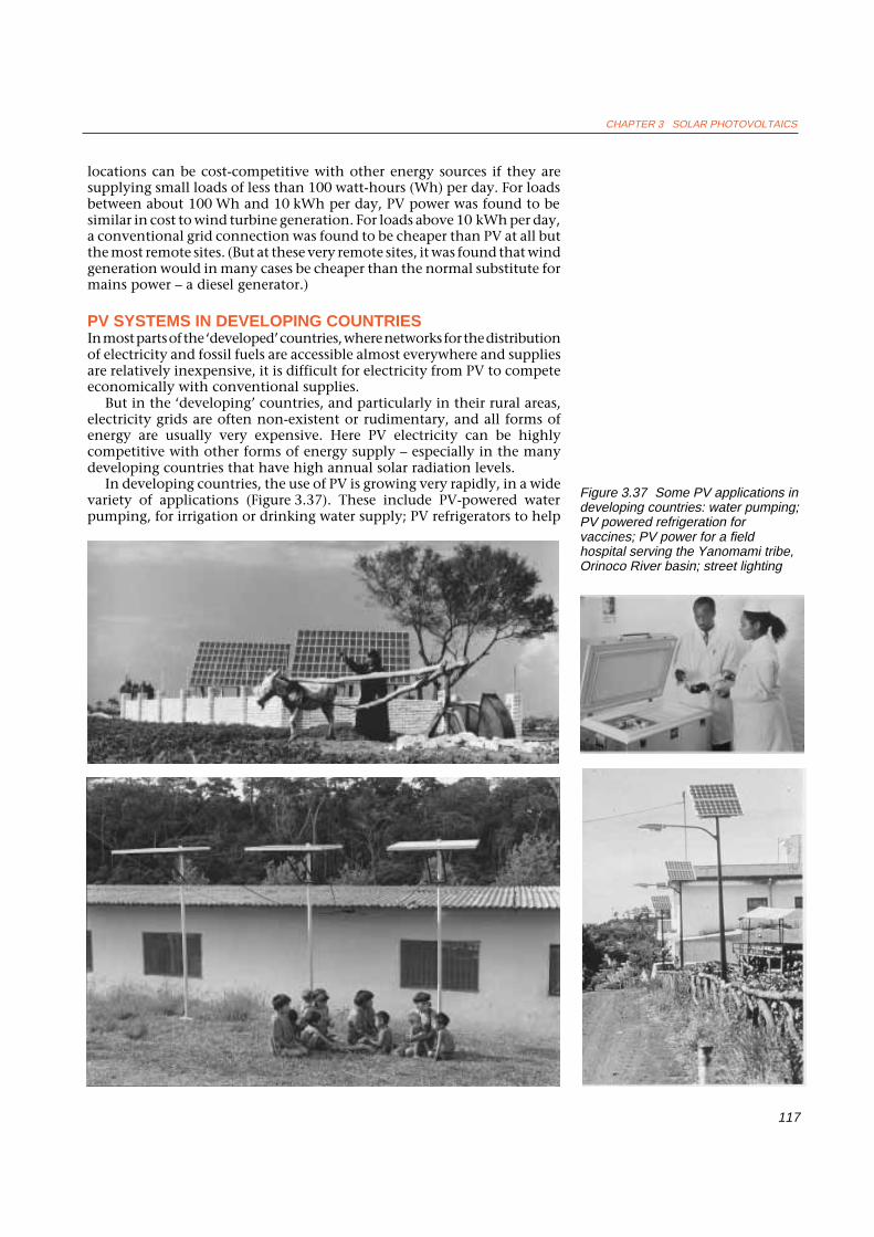
In developing countries, the use of PV is growing very rapidly, in a widevariety of applications (Figure 3.37). These include PV-powered waterpumping, for irrigation or drinking water supply; PV refrigerators to help
Figure 3.37 Some PV applications indeveloping countries: water pumping;PV powered refrigeration forvaccines; PV power for a fieldhospital serving the Yanomami tribe,Orinoco River basin; street lighting

RENEWABLE ENERGY
118
keep vaccines stored safely in health centres; PV systems for homes andcommunity centres, to provide energy for lights, radios, audio- and video-cassette players and television sets; PV-powered telecommunicationssystems; and PV-powered street lighting.
In Mali, for example, more than 80 photovoltaically-powered waterpumping systems have been installed over the last decade, most of themunder the auspices of a charity, Mali Aqua Viva (MAV), with funding fromvarious aid agencies. As McNelis et al. (1992) point out, the success of theseschemes is due to a combination of technological, economic, social andinstitutional factors:
Most of the systems installed have been for village water supplies and have beenwell-appreciated by the users. Arrangements for technical support have beenestablished, so that on-going advice can be given and faults corrected. The MAVapproach to all their water supply improvement projects is to involve the localpeople from the beginning, to ensure their full understanding and commitment. Inthe case of solar pumps, the villagers are expected to build as much of the localinfrastructure as possible (e.g. storage tanks, access, foundations) and this meansthat a significant proportion of the total capital cost (up to 25 per cent) is met fromlocal sources. The motivation generated by this initial involvement has proved tobe a key factor in the successful implementation of most of the MAV projects.
The United States government is one of several that have recognised theenormous export potential of PV electricity systems for developing countriesover coming decades. As part of its ‘Solar 2000’ initiative, aimed atinstalling 1400 MW of US-made PV systems by the end of the decade(900 MW in the USA and 500 MW in developing countries), the USDepartment of Energy is involved in several international partnerships.
One of these, called project FINESSE (Financing Energy Services for SmallScale End Users), was set up in 1989 by the World Bank. It includes thegovernments of the USA, the Netherlands and various other governmentaland non-governmental organisations, and aims to overcome the financialand institutional constraints to implementing PV systems in developingcountries. The FINESSE approach involves ‘bundling’ together a number ofsmall-scale energy schemes into one larger package that can be financed asa single unit. Opportunities for funding some $800 million worthof PV and other renewable energy schemes have been identified in theAsian region alone, and an Asia Alternative Energy Unit has been set upwithin the World Bank to help bring these schemes to fruition.
Under the auspices of another project, the ‘America’s 21st CenturyProgram’, which aims to develop sustainable energy sources for the Caribbeanand Latin America, US support is being given to the Mexican ‘NationalSolidarity Program’, a public anti-poverty programme which has facilitatedthe installation of some 18 000 PV systems in rural areas of Mexico,including systems in homes, health clinics and schools.
The America’s 21st Century Program also supports an ambitious projectin Brazil which aims to use PV and PV-hybrid systems to electrify some500 000 homes, schools and health clinics, starting with 1000 homes in theState of Pernambuco and 1000 homes and a model village in the State ofCeara (see Rannels, 1992).
European Commission officials have also recognised the huge potentialcontribution that PV could make towards improving the living standardsof the 1.1 billion people who are classified by the World Bank as ‘poor’.They have proposed a ‘Power for the World’ programme (Palz, 1994) inwhich approximately 10 watts of PV capacity per person, used to meet basichealth, lighting, educational and communication needs, would be installedin villages in a major collaboration between developed and developingcountries over the next 20–25 years.

CHAPTER 3 SOLAR PHOTOVOLTAICS
119
3.10 GRID-CONNECTED PV SYSTEMSGRID-CONNECTED PV SYSTEMS FOR RESIDENCESPV energy systems are not all of the ‘stand-alone’ or ‘autonomous’ type.
The Rappenecker Hof case study demonstrates that non-grid-connectedPV systems can be economically justifiable in some remote locations – evenin the ‘developed’ countries. But in most parts of the developed world, gridelectricity is easily accessible as a convenient backup to PV or otherrenewable energy supplies. Here it makes sense for operators of PV energysystems to use the grid as a giant ‘battery’. The grid can absorb PV power thatis surplus to current needs (say, on sunny summer afternoons), making itavailable for use by other customers and reducing the amount that has tobe generated by conventional means; and at night or on cloudy days, whenthe output of the PV system is insufficient, it can provide backup energyfrom conventional sources.
In these grid-connected PV systems, a so-called ‘grid-commutated inverter’(or ‘synchronous inverter’) transforms the DC power from the PV arraysinto AC power at a voltage and frequency that can be accepted by the grid,while ‘debit’ and ‘credit’ meters measure the amount of power bought fromor sold to the utility.
In Germany, where there is strong support for the development of PVtechnologies, the Federal Ministry of Research and Technology (BMFT) andthe federal States are together subsidising the installation of small (1–5 kW)grid-connected PV systems on the roofs of 2250 houses. The performanceof these is being carefully monitored.
In Switzerland, the installation of domestic grid-connected PV systemsis encouraged, and under ‘Project Megawatt’ over one hundred 3 kW grid-connected PV systems have been installed in residential and businesspremises since 1987.
In Japan, high land costs should make roof-mounted PV systemsattractive (Figure 3.38). An extensive research programme has been
Figure 3.38 Roof-top, grid-connectedPV system on the ‘Eco-EnergyHouse’, near Tokyo in Japan
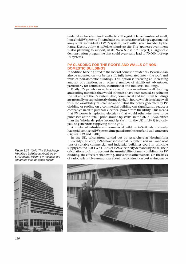
RENEWABLE ENERGY
120
undertaken to determine the effects on the grid of large numbers of small,household PV systems. This includes the construction of a large experimentalarray of 100 individual 2 kW PV systems, each with its own inverter, by theKansai Electric utility at its Rokko Island test site. The Japanese governmentis also planning to support, in its “New Sunshine” Project, a large-scaledemonstration programme that could eventually lead to 70,000 roof-topPV systems.
PV CLADDING FOR THE ROOFS AND WALLS OF NON-DOMESTIC BUILDINGSIn addition to being fitted to the roofs of domestic residences, PV arrays canalso be mounted on – or better still, fully integrated into – the roofs andwalls of non-domestic buildings. This option is receiving an increasingamount of attention, as it offers a number of significant advantages,particularly for commercial, institutional and industrial buildings.
Firstly, PV panels can replace some of the conventional wall claddingand roofing materials that would otherwise have been needed, so reducingthe net costs of the PV system. Also, commercial and industrial buildingsare normally occupied mostly during daylight hours, which correlates wellwith the availability of solar radiation. Thus the power generated by PVcladding or roofing on a commercial building can significantly reduce acompany’s need to purchase electrical power from the utility. This meansthat PV power is replacing electricity that would otherwise have to bepurchased at the ‘retail’ price (around 8p kWh–1 in the UK in 1995), ratherthan the ‘wholesale’ price (around 3p kWh–1 in the UK in 1995) typicallypaid to generators supplying to the grid.
A number of industrial and commercial buildings in Switzerland alreadyhave grid-connected PV systems integrated into their roof and wall structures(Figures 3.39 and 3.40a).
In the UK, calculations carried out by researchers at NorthumbriaUniversity (Hill et al., 1992) have shown that PV systems on walls and rooftops of suitable commercial and industrial buildings could in principlesupply around 360 TWh (120% of 1992 electricity demand) by 2020. Theircalculations took into account the unsuitability of many buildings for PVcladding, the effects of shadowing, and various other factors. On the basisof various plausible assumptions about the construction cost savings made
Figure 3.39 (Left) The ScheideggerMetallbau building at Kirchberg inSwitzerland; (Right) PV modules areintegrated into the south facade
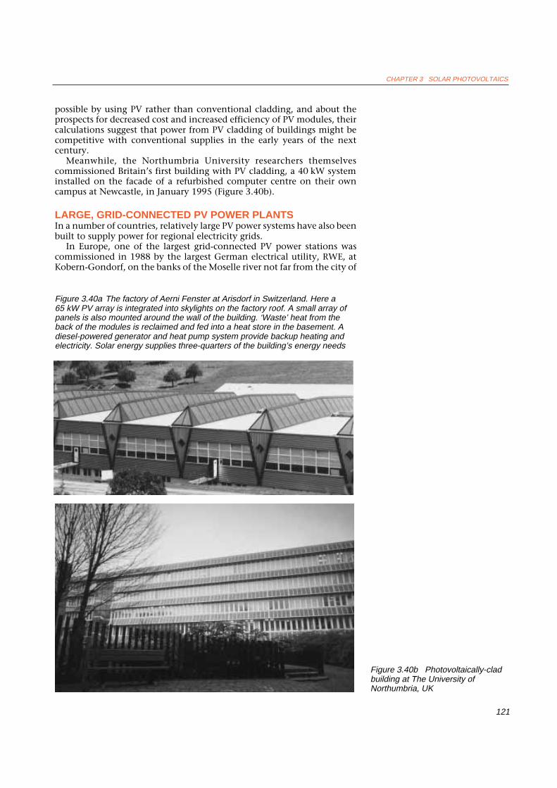
CHAPTER 3 SOLAR PHOTOVOLTAICS
121
possible by using PV rather than conventional cladding, and about theprospects for decreased cost and increased efficiency of PV modules, theircalculations suggest that power from PV cladding of buildings might becompetitive with conventional supplies in the early years of the nextcentury.
Meanwhile, the Northumbria University researchers themselvescommissioned Britain’s first building with PV cladding, a 40 kW systeminstalled on the facade of a refurbished computer centre on their owncampus at Newcastle, in January 1995 (Figure 3.40b).
LARGE, GRID-CONNECTED PV POWER PLANTSIn a number of countries, relatively large PV power systems have also beenbuilt to supply power for regional electricity grids.
In Europe, one of the largest grid-connected PV power stations wascommissioned in 1988 by the largest German electrical utility, RWE, atKobern-Gondorf, on the banks of the Moselle river not far from the city of
Figure 3.40b Photovoltaically-cladbuilding at The University ofNorthumbria, UK
Figure 3.40a The factory of Aerni Fenster at Arisdorf in Switzerland. Here a65 kW PV array is integrated into skylights on the factory roof. A small array ofpanels is also mounted around the wall of the building. ‘Waste’ heat from theback of the modules is reclaimed and fed into a heat store in the basement. Adiesel-powered generator and heat pump system provide backup heating andelectricity. Solar energy supplies three-quarters of the building’s energy needs

RENEWABLE ENERGY
122
Koblenz (see Figure 3.41). The location, on a hilltop just above a vineyard,was chosen because it had relatively high annual solar radiation levels forthe region (around 1100 kWh m–2), with minimal fog and good access tothe grid. The plant has a capacity of 340 kW and its annual output is around250 000 kWh.
The main aim of the project was to evaluate the efficiency, reliability andcost-effectiveness of various PV modules, support structures, inverters andinstallation techniques, and to give the utility practical experience inoperating a large PV power plant connected to its network. Another aim ofthe project was to assess how best to integrate PV power systems into thesurrounding environment.
The PV modules tested at Kobern-Gondorf are from a wide variety ofEuropean, American and Japanese manufacturers, including AEG inGermany, Chronar in France, Hoxan in Japan, and Arco Solar, Mobil,
Figure 3.41 (Top) The 340 kW RWEPV power plant at Kobern-Gondorf,Germany; (Bottom) Phase 2 of theRWE project: the 300 kW PV plant atLake Neurath

CHAPTER 3 SOLAR PHOTOVOLTAICS
123
Sovonics and Solarex in the USA. Some of the modules use monocrystallinesilicon, others polycrystalline silicon and others amorphous silicon, andtheir efficiencies range from 4% to over 13%. The most efficient modulesare those from Hoxan of Japan, which are made of monocrystalline siliconand are 13.3% efficient.
To try to optimise the integration of the overall PV plant into itsenvironment, RWE has turned the surrounding area, which was previouslyfallow land, into a nature reserve for endangered species of flora and fauna.The total land area occupied by the plant is some 50 000 m2 (0.05 km2) –although this area was chosen to allow expansion at a later date.
To evaluate how PV modules can best be integrated into buildings, theroof of the building which houses the equipment for the plant is also usedfor PV power generation. The building also houses an information centre,where the company gives lectures and guided tours of the plant to 2000visitors a month.
The performance of the Kobern-Gondorf plant has been carefullymonitored, and lessons learned have been taken into account in the designof the second phase of the project, a 300 kW plant at Lake Neurath whichstarted operation in 1991 (Figure 3.41). This plant uses large area modules,large supporting structures and a single inverter operating at high voltage.(See Beyer and Pottbrock, 1989 and Beyer, Pottbrock and Voermans, 1992.)
RWE is also part of a consortium that has constructed a large, 1 MW PVplant near Toledo in Spain. Half of the modules used are of BP Solar’s high-efficiency monocrystalline type, and the plant is operated in conjunctionwith a hydroelectric scheme.
In Switzerland, a 500 kW grid-connected PV plant was installed in 1992on Mont Soleil in the canton of Berne (Figure 3.42). The plant cost8.5 million Swiss francs (£3.8 million), occupies 20 000 m2 of land, andconsists of 110 arrays of monocrystalline silicon PV modules made bySiemens Solar. Each array has a nominal capacity of 5 kW, the total area ofthe arrays is 4575 m2, and the total annual output of the plant is estimatedat around 700 000 kWh. It was 50% funded by a consortium of nine utilitiesand two industrial companies, and 50% by the Swiss National Energy Fundand the Canton of Berne (Minder, 1993).
Figure 3.42 The 500 kW Phalk-Mont Soleil PV power plant in Switzerland

RENEWABLE ENERGY
124
Another country that is actively developing large, grid-connected PVpower plants is Italy. These include a 300 kW PV system which has operatedsuccessfully for a number of years on a seven hectare site at Delphos, nearFoggia in southern Italy. The system was expanded to 600 kW in 1991(Figure 3.43). An even larger, 3.3 MW plant has been built near Naples asa contribution to Italy’s national energy plan, which has as one of its targetsthe installation of 25 MW of PV capacity by 1995.
In the USA, a number of large grid-connected PV plants have beenconstructed over the past decade. Two pioneering systems were constructedby the Arco Solar company in California in the early 1980s. One was a 1 MWsystem at Lugo, near Hesperia, the other a 6.5 MW system at Carissa Plain.Both employed an advanced, two-axis tracking array design. The Carissaplant had two reflectors on either side of each array to concentrate the solarradiation by a factor of about two. Unfortunately, the high moduletemperatures generated by the reflectors caused degradation of theencapsulant of some of the modules. Although the systems were successfulapart from this design defect, both were dismantled in the early 1990s andtheir component PV modules sold off for continuing use in smaller, remotepower systems.
Figure 3.45 The Photovoltaics for Utility Scale Applications (PVUSA) test site atDavis, California
Figure 3.44 Part of the 2 MWSacramento Municipal Utility District(SMUD) PV power plant in California
Figure 3.43 The 600 kW PV power plant at Delphos in southern Italy

CHAPTER 3 SOLAR PHOTOVOLTAICS
125
receiving antenna
very large orbiting photovoltaic array
antenna beams power to earth by microwave
Figure 3.46 The satellite solar powerstation (SSPS) concept
Other notable large US PV installations include two 1 MW plants, usingsingle-axis tracking arrays, constructed in California for the SacramentoMunicipal Utility District (SMUD) (Figure 3.44), and a 300 kW arrayproviding power for the 3M Company’s research centre at Austin, Texas(see Figure 3.28).
An increasingly important focus for PV developments in the UnitedStates is the PVUSA (Photovoltaics for Utility Scale Applications) project,which involves a number of electrical utilities, the US Department ofEnergy and the California Energy Commission. At the main PVUSA test siteat Davis, California, there are a number of smaller arrays of around 20 kWcapacity in which various ‘emerging module technologies’ are beingdemonstrated and evaluated. Several ‘utility-scale’ arrays of200–400 kW capacity, each employing a different PV technology, have alsobeen installed and are undergoing careful evaluation (Figure 3.45).
All these projects could eventually be dwarfed in scale if proposals tobuild a 100 MW PV power plant at a former nuclear test site in the Nevadadesert come to fruition. The project has been proposed by Amoco-EnronSolar, a partnership between the major US oil company Amoco (whichowns the PV manufacturer Solarex) and Enron, the largest producer ofnatural gas in the USA. The project would use amorphous silicon PVmodules produced in a specially-built manufacturing plant nearby. Thecompany claims that the installation would cost $150 million to build andcould produce power for 5.5 cents per kWh, given the high solar radiationlevels in the area.
SATELLITE SOLAR POWERProbably the most ambitious – and some would say the most fanciful –proposal for a ‘grid-connected’ PV plant is the Satellite Solar Power System(SSPS) concept, first suggested more than 20 years ago (Glaser, 1972). Thebasic idea is to construct a huge PV array, perhaps as large as 30 km2 andproducing several GW, in geostationary orbit around the earth. The DCpower generated would be converted to microwave radiation at a frequencyof around 2.45 GHz and beamed, at a power density of some 250 W m–2,from a 1 km diameter transmitting antenna in space to a 100 km2 receivingantenna on earth. The received power would then be converted to 50 Hzalternating current and fed into the grid (Figure 3.46).The advantages of the SSPS are, in theory, very substantial. In space, the PVarrays would receive a full 1365 W m–2 of solar power, instead of the1000 W m–2 that is the maximum available at the earth’s surface. Moreover,this high power would be available virtually constantly (except for occasionaleclipses). And in the weightless and airless space environment, it should bepossible to construct extremely large but very light structures to support thePV arrays, without having to worry about the effects of wind and weather– though meteorites might be a problem.
On the other hand, the engineering challenges in constructing an SSPS,and the associated capital costs, would be enormous. One US studyestimated that a system producing 5 GW on earth would cost some$15 000 million at 1980 prices. Such an installation, clearly, could only beafforded by the richest of nations.
There are also considerable anxieties about the health effects which themicrowave beam might have on anything passing through it, or around thefringes – not to mention what might happen in the event of a malfunctionin the ‘fail safe’ control system that should ensure the beam always pointsat the receiving antenna. Interference with communications and radioastronomy could also be a problem.
Concerns like these have, up to now, meant that the SSPS has remainedon the drawing board. (See also Glaser, 1992.)

RENEWABLE ENERGY
126
3.11 ECONOMICS OF PV ENERGY SYSTEMSAs with any energy source, the price of power from PV cells consistsessentially of a combination of the capital cost and the running cost.
The capital cost of a PV energy system will include not only the cost of thePV modules themselves, but also the so-called ‘balance of system’ (BOS)costs, i.e. the costs of the interconnection of modules to form arrays, thearray support structure, land and foundations (if the array is not roofmounted), the costs of cabling, charge regulators, switching and inverters,plus the cost of storage batteries or connection to the grid.
Although the initial capital costs of PV systems are currently high, theirrunning costs should be very modest in comparison with those of otherrenewable or non-renewable energy systems. Not only does a PV system notrequire any fuel, but also, unlike most other renewable energy systems, it hasno moving parts (except in the case of tracking systems) and should requiremuch less maintenance than, say, a wind turbine.
However, PV arrays need washing from time to time, to remove the dustand dirt that accumulates on them – particularly in urban locations. Thearrays are also subject to the effects of the elements. High winds can twistand distort the support structures and cause cells or modules to becomecracked or disconnected. Water can cause corrosion to metal parts and mayin some cases penetrate the laminations protecting the cells, leading toincreased resistive losses or even short circuits. The expansion and contractioncaused by the daily solar heating and cooling of the array can also causecracks, short circuits or disconnections.
Most of these problems can be overcome, or at least minimised, by carefulattention to material specification and detailed design, and by good qualityassurance during the manufacture of the system. So a well-designed PV arrayshould need little maintenance other than washing every few months andperhaps an occasional coat of paint on its support structures every few years.
The solid-state electronic charge regulation and power conditioningequipment used in PV systems is also, in principle, very reliable. But allelectronic equipment can develop occasional component failures whichrequire specialist repair.
PV systems with battery storage have additional maintenancerequirements, however. The most common PV storage battery, the lead-acidtype, needs checking for terminal corrosion and ‘topping-up’ with distilledwater every few months. (‘Maintenance-free’ lead acid batteries, whichrequire attention only every few years, are available for PV systems, but costmore than conventional batteries.) These maintenance functions, thoughmodest, still involve some cost – especially if someone has to be paid to carrythem out.
Finally, the owner of a PV system may consider it desirable to take outinsurance to cover the cost of replacing the system in case of fire, or accidentor other calamity. For a small domestic system, such risks would probablybe covered by an existing household insurance premium. For a large system,insurance costs could be significant – but still small in relation to the totaloverall costs.
In order to try to estimate what the actual costs of PV power, in pence perkWh, are likely to be under UK conditions, let’s look again at the small PVsystem for a remote household discussed above in Section 3.9, and then atthe large, grid-connected PV system described in Section 3.10.
COST OF POWER FROM A SMALL PV SYSTEM IN THE UKAlthough the price of the PV modules used in large, megawatt-scale systemshas now fallen to below $5 (£3) per peak watt of installed capacity (seebelow), smaller systems do not benefit from economies of scale in purchasing,installation and ‘balance of system’ components.

CHAPTER 3 SOLAR PHOTOVOLTAICS
127
The capital cost of the small, single-module, 50 W(p) PV system describedin Section 3.9 is around £400 ($600, or $12 per W(p): all costs are in 1994prices), of which the cost of the 50 W module accounts for some £250. Letus assume that this capital is repaid over the lifetime of the system, whichshould be 20 years, and that interest on the capital is charged at a ‘real’ rateof 8% (i.e. 8% plus inflation). The annual cost of the capital (including bothinterest and repayment of principal) can be calculated using the annuitytable in the Appendix, and in this case it works out at about £40.
Let us assume in this case that occasional maintenance is carried out bythe householder free of labour costs, that insurance is included in thehousehold policy, and that (for simplicity) we treat as a ‘running cost’ thecost of replacing the battery every five years or so. At a price of £80 perbattery the latter works out at £16 per annum, and so the total cost of thesystem is around £56 per year.
If we assume an annual average energy conversion efficiency of 10%, theannual output of the 50 W(p) system should be around 50 kWh per year,given a typical UK annual total solar radiation level of 1000 kWh m–2 ayear. However, we must remember that not all of the output of the PV arraywould actually be used, partly because of losses in the battery and wiring,and partly because the residents of the holiday home would not always bethere to use it. If we assume that the net useful power is 25 kWh a year, thenthe cost of every kWh is £56 divided by 25, i.e. £2.24. This is 28 times the1995 UK domestic electricity price of around 8p kWh–1 on-peak, and 75times the off-peak price of 3p kWh–1.
However, this calculation excludes the standing charges of around £40per year that would be payable if the home were connected to the grid. Fora grid-connected household using only 25 kWh per year of electricity(assuming half of consumption is off-peak) the total cost would be£40 + (13 × 0.08) + (12 × 0.03) = £41.40, i.e. some £1.66 per kWh.Nevertheless, the cost per kWh of power from the PV system is still abouta third more than that from the grid. But this excludes the capital cost ofgrid connection, which as we have seen can be extremely high.
Of course, if our remote holiday home were connected to the grid, thenthe inhabitants would almost certainly use more electricity, the proportionof costs accounted for by standing charges would reduce, and the cost perkWh would drop rapidly as consumption increased. Nevertheless, thisexample underlines the point made earlier that, for low levels of energyconsumption, PV systems can sometimes be competitive with grid electricityin remote locations.
COST OF POWER FROM A GRID-CONNECTED PV SYSTEMIN THE UKThe installed capital cost of a large, grid-connected PV power plant, suchas the 500 kW installation at Mont Soleil in Switzerland, is typically aroundUS$11 per peak watt of net AC output to the grid (Shugar et al., 1993). Thisincludes the cost of the PV arrays, support structures, power conditioning,grid connection, etc. The Mont Soleil plant has a total array area of some4500 m2, produces some 750 000 kWh a year of power for the grid, and costsome £3.8 million. It is only fair to point out that because the plant is a one-off demonstration project, this price is substantially higher than it mightotherwise be.
However, solar radiation levels are higher in Switzerland than in Britain.In UK conditions, again assuming the annual total solar radiation is1000 kWh m–2 and that 10% is the annual average PV array efficiency, theannual output of a 500 kW plant like the one at Mont Soleil would bearound 100 kWh m–2, or 450 000 kWh.

RENEWABLE ENERGY
128
Assuming the capital cost of £3.8 million is to be repaid over 25 years andinterest paid at a real rate of 8%, using the amortisation table in theAppendix we can see that the annual capital cost (interest and repaymentof principal) would be about £357 000.
The running costs are difficult to calculate, since there is little or noexperience of operating large PV plants in Europe, but one ‘rule of thumb’estimate used in the industry is that annual running costs are likely to bearound 1% of the initial capital cost, which in this case would be £38 000a year. The total yearly cost therefore becomes £395 000 and as the totalannual output is some 450 000 kWh, the cost of electricity works out ataround 78p kWh–1.
So the power from this large, grid-connected PV array would cost aboutone-third of that from the small household system we examined earlier.This is partly due to its slightly lower initial capital cost per watt of capacity,partly due to its lower running cost (because the system is grid connectedand does not need batteries), and partly because all the energy produced isactually used. Nevertheless, its power is still about 10 times as expensive asconventional on-peak electricity in the UK.
How do these costs compare with the cost of power from smaller roof-topPV systems that are not autonomous but connected to the grid? A recentdetailed study by Shugar et al. (1993) found that when all relevant factorswere taken into account, the overall costs were currently about the same.
It seems that there is still some way to go before grid-connected PVsystems in the UK become competitive with power from conventionalsources. However, smaller grid-connected PV systems supplying powerdirectly to users have a considerable advantage in that they are competingwith power supplied at ‘retail’ prices, rather than the lower wholesale priceswhich would apply to larger PV plants supplying power for the generalelectricity market.
REDUCING THE COSTS OF POWER FROM PVHow, then, might the price of PV power be made more competitive?
The answers are fairly obvious. Firstly, the installed cost per peak wattneeds to drop substantially. Many industry analysts are confident that PVmanufacturing costs will fall to around $1.50 per watt by the early years ofthe next century, and that a profitable selling price for modules in largesystems by then will be about $2 W(p)–1.
Secondly, the overall annual conversion efficiency of the PV arrays needsto increase substantially from its present figure of around 10%, achieved bycurrent PV modules with peak efficiencies of around 13%. It takes around10 years for the PV efficiencies achieved in the laboratory to be reflected inthe actual efficiencies of commercially available modules. So, by the earlyyears of the twenty-first century, it may be possible to buy PV moduleshaving a peak efficiency of around 23% and an annual average efficiencyof, say, 20%.
Thirdly, the ‘balance of system’ costs – i.e. the costs of support structures,wiring, inverters, grid connection, etc. – need to be substantially reduced.In existing PV systems the balance of system costs are roughly equal to themodule costs, so to keep this ratio these costs also need to be reduced toaround $2 per watt. This seems feasible, given volume production of BOScomponents and the likelihood of substantially reduced installation costswhen the industry has gained more experience and is installing moresystems. A plausible target for overall system cost by, say, 2005 is therefore$4 (£2.66) per peak system watt.
Using this figure to recalculate the costs of the 500 kW PV power stationin the example above, we get a total capital cost of £1.33 million, a totalannual cost of some £138 000, an annual output of 900 000 kWh, and so

CHAPTER 3 SOLAR PHOTOVOLTAICS
129
a cost per kWh of delivered power of about 15p kWh–1. This is still nearlytwice the current on-peak price, but at least within striking distance ofcurrent prices. If a real discount rate of 5% p.a. rather than 8% p.a. were usedin calculating the costs, they would reduce further to around 12p kWh-1. If,as many PV advocates suggest, the full ‘external’ costs of conventionalenergy sources (acid rain, greenhouse gas emissions, oil spills, accidents,etc.) were to be taken into account, then their price might well rise toapproach that of power from PV (see Hohmeyer, 1988).
The economics of PV power plants are, however, much more attractivein those areas of the world that have substantially greater annual total solarradiation than northern Europe. Areas such as north Africa or southernCalifornia not only have annual solar radiation totals more than twicethose in Britain, but also have clear skies. This means that the majority ofthe radiation is direct, making tracking and concentrating systems effectiveand further increasing the annual energy output. The price of electricityfrom such PV installations is likely to be less than half of that from acomparable non-tracking installation in the UK, and close to beingcompetitive with conventional sources.
In the USA and some other countries, electricity utilities have foundanother useful role for PV power systems: that of grid reinforcement. Insome areas, increasing demands for electricity would normally make itnecessary to install new power lines, transformers and switching equipment,or upgrade the capacity of existing electricity distribution systems. Instead,PV power systems are being installed near the point of demand. Outputfrom the PV systems is usually highest during the day, when demand forelectricity is also high. The PV system therefore effectively reduces theamount of power that has to be transmitted over the power lines fromcentralised generation plant. In many cases, grid reinforcement using PVwould be cheaper than upgrading the electricity distribution system.
3.12 ENVIRONMENTAL IMPACT AND SAFETYENVIRONMENTAL IMPACT AND SAFETY OF PV SYSTEMSProponents of PV energy systems often claim that their environmentalimpact is less than that of any other renewable or non-renewable energysystem.
Clearly, in normal operation PV energy systems emit no gaseous orliquid pollutants, and no radioactive substances. However, in the case ofCIS or CdTe modules, which include small quantities of toxic substances,there is a slight risk that a fire in an array might cause small amounts of thesechemicals to be released into the environment.
Since PV modules have no moving parts they are also safe in themechanical sense, and they emit no noise. However, as with other electricalequipment, there are some risks of electric shock – especially if, as in somesystems, the DC voltages used are substantially higher than the 12–48 voltsemployed in most small PV installations. But the electrical hazards of a well-engineered PV system are, at worst, no greater than those of other comparableelectrical installations.
PV arrays do, of course, have some visual impact on the environment.Roof-top arrays will be clearly visible to neighbours, and may be regardedas either attractive or unattractive according to aesthetic tastes. Severalcompanies, including Sanyo in Japan and BMC Solartechnik in Germany,have produced PV modules in the form of special roof tiles that shouldblend into roof structures more unobtrusively than current module designs.
Large, grid-connected PV arrays will usually be installed on land speciallydesignated for the purpose – although this need not always be the case. As

RENEWABLE ENERGY
130
shown in Figure 3.47, the Swiss authorities are installing large PV arrays asnoise barriers alongside motorways and railways. Arguably PV is herereducing the overall environmental impact.
Whether or not the appearance of a large PV power plant such as that atKobern-Gondorf is aesthetically pleasing or not is again very much a matterof taste – though most people would probably regard it as more attractivethan a conventional power station. RWE envisages the Kobern-Gondorfplant as one of many that could be installed on marginal land, which is notused for other purposes. The land immediately surrounding the Kobern-Gondorf PV arrays has been turned into a nature reserve – again, this isarguably an overall environmental improvement.
Furthermore, because of the need to space the arrays some distance fromone another to avoid overshadowing, it would be possible, for example, togrow some crops on the land between the arrays – or perhaps, in a suitablelocation, even to include some wind turbines.
Indeed, according to some calculations (US Department of Energy, 1989)the net area of land made unavailable for other uses by PV power plants issignificantly less than for coal or nuclear energy, when all associated landuses, including mining, processing, etc., are taken into account.
ENVIRONMENTAL IMPACT AND SAFETY OF PV MODULEPRODUCTION AND RECYCLINGThe environmental impact of the manufacture of silicon PV cells is unlikelyto be significant – except perhaps in the case of accidents at the manufacturingplant. The basic material from which 99% of the cells are made, silicon, isnot intrinsically harmful. However, as with any chemical process, carefulattention must be paid to plant design and operation, to ensure thecontainment of any toxic or potentially harmful chemicals in the event ofan accident or plant malfunction. The need for a stringent approach tosafety in the PV industry – as in any other manufacturing industry – isrecognised by all responsible manufacturers.
Finally, even though PV arrays are potentially very long-lived devices,eventually they will come to the end of their useful life and will have to bedisposed of – or, preferably, recycled. Especially in the case of PV modulescontaining small but not insignificant quantities of toxic metals, saferecycling and disposal methods will have to be developed to ensure thatthese substances are not released into the environment.
Figure 3.47 PV arrays providingsound barriers in Switzerland: (Left)alongside a motorway; (Right)alongside a railway line

CHAPTER 3 SOLAR PHOTOVOLTAICS
131
ENERGY BALANCE OF PV SYSTEMSA common misconception about PV cells is that almost as much energy isused in their manufacture as they generate during their lifetime. This wasprobably true in the early days of PV, when the refining of monocrystallinesilicon and the Czochralski process were very energy-intensive, and theefficiency of the cells produced was relatively low, leading to low lifetimeenergy output.
However, with the more modern PV production processes introduced inrecent years, and the improved efficiency of modules, the energy balanceof PV is now much more favourable. A recent study by European Commissionscientists (Palz and Zibetta, 1992) has shown that in average Europeanconditions the energy payback time for PV modules (excluding the otherelements of a PV power plant) ranges from about 2.1 years for crystallinesilicon to 1.2 years for amorphous silicon. These figures were based on1990 manufacturing conditions, and the authors believe there isconsiderable scope for further reductions in these payback periods incoming years.
3.13 INTEGRATION OF PV INTO FUTUREENERGY SYSTEMSIf PV energy systems continue to improve in cost-effectiveness comparedwith more conventional sources, as many PV enthusiasts believe they will,how might they be integrated into national energy supply systems – andspecifically that of the UK? How much energy might they supply? Whatareas and installed capacities of PV arrays would be required? What energyneeds would they be best suited to supplying? In what way would nationalenergy systems need to be modified to cope with the long, medium andshort-term fluctuations in the output of PV arrays?According to a UK government report (Department of Energy, 1989), anumber of very large, grid-connected PV power stations, occupying some2.5% of the UK land area, could in principle supply some 300 TWh ofelectricity a year – about the same as the current total annual UK electricityproduction. In addition, decentralised PV power systems on roof topscould, the report estimated, generate another 26 TWh a year, about 9% ofcurrent demand.
The report estimated that a land area of ‘200 to 300 square kilometres’would be required for a single 2 GW PV power station. However, the actualsurface area of the PV arrays themselves would be very much less than this– and in any case, it is very unlikely that individual PV power stationswould be built in sizes as large as 2 gigawatts. Also, as explained above, thePV arrays need to be spaced some distance apart in order to avoidovershadowing, and the land between the arrays could be used for otherpurposes.
To calculate the required spacing and layout of the PV arrays, variousfactors have to be considered, including the size and inclination of thearray, the topography of the site, whether or not the arrays are fixed or trackthe sun, and the daily and seasonal variations in the azimuth and elevationof the sun’s position. Computer programs have been developed to assist insuch calculations.
The 500 kW Mont Soleil plant in Switzerland, described in Section 3.10,occupies 20 000 m2 of land, about 4.5 times the area of the PV modulesused. A hypothetical 2 GW PV power plant at Mont Soleil would occupy4000 times as much land as a 500 kW plant – namely 80 km2, rather than200–300 km2.
The discrepancy between this land area figure and that quoted in theDepartment of Energy report may be explained by (a) the likelihood that

RENEWABLE ENERGY
132
the UK calculation was based on the use of PV modules of somewhat lowerefficiency than those at Mont Soleil; (b) the overshadowing calculationsmay have been based on different assumptions; and (c) there may have beena greater allowance for additional land for buildings and roads associatedwith the plant.
As pointed out in Section 3.11 above, the cost of power from such PVplants in the UK would be prohibitive at current prices. The DEn reportsuggested that the maximum achievable contribution of PV to UK generatingcapacity would be 2 GW by 2005 and 5 GW by 2020, respectively some 4%and 9% of current UK generating capacity. Its estimate of the range of PVpower costs by 2020 was between 3 and 41 pence per kWh, with a mid-pointestimate of 22p kWh–1 (at 1989 prices).
A more recent report (ETSU, 1994) estimated that the contribution to UKelectricity demand from decentralised PV systems by 2025 could range from0.3 Twh per year in a ‘Low Oil Price’ scenario to 7.2 TWh in a ‘HeightenedEnvironmental Concern’ scenario (assuming an 8% discount rate in bothcases).
A problem with PV power in the UK is that much of it would be producedin summer, when electricity demand is relatively low, and much less wouldbe produced in winter, when demand is high. Also, although PV power isquite reliable (during daylight hours) in climates with mainly clear skies, itcan be highly intermittent in countries like the UK, where passing cloudscan reduce power output dramatically within seconds.
But as long as the capacity of variable output power sources such as PVis fairly small in relation to the overall capacity of the grid (most studiessuggest a proportion of 10–20%), then there should not be a major problemin coping with the fluctuating output. The grid is, after all, designed to copewith massive fluctuations in demand, and similarly fluctuating sources ofsupply like PV can be treated as ‘negative loads’. Fluctuations would also, ofcourse, be substantially smoothed out if PV power plants were situated inmany different locations subject to widely varying solar radiation andweather patterns.
However, if PV power stations, and other fluctuating output renewableenergy sources such as wind power, were in future to contribute more thanabout 20% of electricity supplies, then the ‘plant mix’ in the grid wouldhave to be changed to include a greater proportion of ‘fast-acting’ powerplant, such as hydro and gas turbines, and increased amounts of short-termstorage and ‘spinning reserve’.
These considerations lead some analysts to suggest that without largequantities of cheap electrical energy storage, renewable energy sources likePV cannot make a major contribution. Whilst this would seem to be anexaggeration, at least for small to medium levels of ‘penetration’ of PV andother renewables into the system, it is certainly true that cheap storage inlarge amounts would make their integration easier.
There has been a recent revival of interest in the use of hydrogen as amedium for energy storage and distribution, particularly in connectionwith PV but also for use with other renewable energy sources. Hydrogenwould be produced by the electrolysis of water, using PV or other renewablesas the electricity source. The hydrogen would be stored and transported towherever it was needed. It could be converted back to electricity, either inan engine-powered generator or, much more efficiently, using fuel cells.Alternatively, the hydrogen could simply be burned to release heat, orconverted into heat by ‘catalytic combustion’ – a chemical reaction with airin the presence of a catalyst.
These issues will be examined in more detail in Chapter 10, Integration.

CHAPTER 3 SOLAR PHOTOVOLTAICS
133
REFERENCESAdams, W. G. and Day, R. E. (1877) ‘The action of light on selenium’,Proceedings of the Royal Society, London, Series A, 25, p. 113.Becquerel, A. E. (1839) ‘Recherches sur les effets de la radiationchimique de la lumière solaire au moyen des courants électriques’ and‘Mémoire sur les effets électriques produit sous l’influence des rayonssolaires’, Comptes Rendus de l’Académie des Sciences 9, pp. 145–149 andpp. 561–567.Beyer, U. and Pottbrock, R. (1989) ‘Design, construction and operationof a 340 kW photovoltaic plant’, Proceedings of 9th EC PhotovoltaicsConference, Freiburg, Germany, 1989, p. 655, Kluwer AcademicPublishers.Beyer, U., Pottbrock, R. and Voermans, R. (1992) ‘1MW PhotovoltaicProject: planning, construction and operation of photovoltaic powerplants’, Proceedings of 11th European Photovoltaic Conference, Gordon andBreach.Boes, E. C. and Luque, A. (1993) ‘Photovoltaic concentrator technology’,in Johansson et al. (eds) (1993) Renewable Energy Sources for Fuels andElectricity, Island Press, Washington DC, pp. 369–370.Bruton, T. M., Nagle, J. P., Mason, N. B. and Russell, R. (1992) ‘Recentdevelopments in concentrator cells and modules using silicon laser-grooved buried-grid cells’, Proceedings of 11th European Photovoltaic SolarEnergy Conference, Montreux, Switzerland, Gordon and Breach.Chapin, D. M., Fuller, C. S. and Pearson, G. L. (1954) ‘A new silicon p–njunction photocell for converting solar radiation into electrical power’,Journal of Applied Physics, 25, pp. 676–677.Chalmers, R. (1976) ‘The photovoltaic generation of electricity’, ScientificAmerican, October, pp. 34–43.Department of Energy (1989) An Evaluation of Energy Related GreenhouseGas Emissions and Measures to Ameliorate Them, Energy Paper 58, pp 58–59, HMSO.Derrick, A. et al. (1991) Solar Photovoltaic Products, IT Publications,London.Derrick, A. (1993) ‘A market overview of PV in Europe’, EuropeanDirectory of Renewable Energy Supplies and Services 1993, James and JamesScience Publishers, London, pp. 114–120.ETSU (1994) An Assessment of Renewable Energy for the UK EnergyTechnology Support Unit, Report R82, page 119.Fraunhofer Institute (1989) Photovoltaics – Made in Germany, pp. 13–14.Information brochure on PV produced for Bundesministerium fürForschung und Technologie, Fraunhofer Institut für SolarEnergiesysteme, Oltmannsstr. 22, 7800 Freiburg, Germany.Fraunhofer Institute (1991) Der Rappenecker Hof: Tradition und ModerneTechnik. Brochure on Rappenecker Hof project.Glaser, P. (1972) ‘The case for solar energy’, paper presented at theannual meeting of the Society for Social Responsibility in Science,Queen Mary College, London, September.Glaser, P. (1992) ‘An overview of the solar power satellite option’, IEEETransactions on Microwave Theory and Techniques, Vol. 40, No. 6, June,pp. 1230–1238.

RENEWABLE ENERGY
134
Green, M. (1982) Solar Cells, Prentice-Hall.Green, M. (1993) ‘Crystalline and polycrystalline silicon solar cells’, inJohansson et al. (eds) (1993) Renewable Energy Sources for Fuels andElectricity, Island Press, Washington DC, pp. 337–360.Gratzel, M. et al. (1989) The Artificial Leaf: Molecular Photovoltaics AchieveEfficient Generation of Electricity from Sunlight, Research Report, EcolePolytechnique Federale Lausanne, Switzerland.Hill, et al. (1992) ‘PV on buildings – estimation of the UK resource’,Proceedings of the 11th European Photovoltaic Solar Energy Conference,Montreux, Switzerland, Gordon and Breach.Hohmeyer, O. (1988) Social Costs of Energy, Springer Verlag, Germany.Imamura, M. S., Helm, P. and Palz, W. (1992) Photovoltaic SystemTechnology: A European Handbook, W. H. Stephens, Bedfordshire, UK, forCommission of European Communities.Lasnier, F. and Ang, T. G. (1990) Photovoltaic Engineering Handbook,Adam Hilger, Bristol and New York.Markvart, T. (ed) (1994) Solar Electricity, John Wiley, Chichester, 248 pp.McNelis, B., Derrick, A. and Starr, M. (1992) Solar Powered Electricity: ASurvey of Photovoltaic Power in Developing Countries, IntermediateTechnology Publications, London, in association with UNESCO.McVeigh, C. (1983) Sun Power, Pergamon, Oxford.Minder, R. (1993) ‘The Swiss 500 kW photovoltaic power plant at Phalk-Mont Soleil’, Proceedings of 11th European Photovoltaic Solar EnergyConference, Montreux, Switzerland, Gordon and Breach.Ohl, R. S. (1941) Light Sensitive Device, US Patent No. 2402622; and LightSensitive Device Including Silicon, US Patent No. 2443542: both filed 27May.O’Regan, B. and Gratzel, M. (1991) ‘A low cost, high efficiency solar cellbased on dye-sensitised colloidal TiO2 films’, Nature, 235, pp. 737–740.O’Regan, B., Nazeruddin M. K. and Gratzel, M. (1993) ‘A very low cost,10% efficient solar cell based on the sensitisation of colloidal titaniumdioxide films’, Proceedings of 11th European Photovoltaics Conference,Montreux, Switzerland, Gordon and Breach.Palz, W. and Zibetta, H. (1992) ‘Energy payback time of photovoltaicmodules’, Yearbook of Renewable Energies 1992, Eurosolar with PontePress, Bochum, Germany, pp. 181–184.Palz, W. (1994) ‘Power for the world: a global photovoltaic action plan’,in McNelis and Jesch (eds) Proceedings of UK International Solar EnergySociety 20th Anniversary Conference, January, ISES, London, pp. 7–41.Piellisch, R. (1991) ‘Solar powered flight’, Sunworld, March–April,pp. 17–20.Rannels, J. E. (1992) Photovoltaics in the Developing World, USDepartment of Energy, Washington DC, USA.Roberts, S. (1991) Solar Electricity: A Practical Guide to Designing andInstalling Small Photovoltaic Systems, Prentice Hall, London.Schmid, J. et al. (1988) ‘A 220 volt AC photovoltaic power supply forremote houses’, Proceedings of 8th EC Photovoltaic Solar Energy Conference,Florence, Italy, pp. 1140–1144, Kluwer Academic Publishers.

CHAPTER 3 SOLAR PHOTOVOLTAICS
135
Shugar, D. S., Real, M. G. and Aschenbrenner, P. (1993) ‘Comparison ofselected economic factors for large, ground-mounted photovoltaicsystems with roof-mounted photovoltaic systems in Switzerland and theUSA’, Proceedings of 11th European Photovoltaics Conference, Montreux,Switzerland, Gordon and Breach.Taylor, E. (1990) Review of Photovoltaic Power Technology, ETSU ReportR50, HMSO.Treble, F. C. (ed.) (1991) Generating Electricity from the Sun, PergamonPress.Treble, F. C. (1993) Solar Electricity: a Layman’s Guide to the Generation ofElectricity by the Direct Conversion of Solar Energy, The Solar EnergySociety, London W3 9PP.US Department of Energy (1989) Energy Systems Emissions and MaterialRequirements, Washington DC, USA.Wilson, H. G., MacCready, P. B. and Kyle, C. R. (1989) ‘Lessons ofSunraycer’, Scientific American, March, pp. 90–97.Zweibel, K. and Barnett, A. (1993) ‘Polycrystalline thin-filmphotovoltaics’, in Johansson et al. (eds) (1993) Renewable Energy Sourcesfor Fuels and Electricity, Island Press, pp. 437–482.
FURTHER READINGProbably the most useful overview of PV is in Renewable Energy Sources forFuels and Electricity (Johansson et al., 1993), which contains more than 200pages of up-to-date information on the subject, spread over six chaptersentitled: ‘Introduction to Photovoltaic Technology’; ‘Crystalline andPolycrystalline Silicon Solar Cells’; ‘Photovoltaic Concentrator Technology’;‘Amorphous Silicon Photovoltaic Systems’; ‘Polycrystalline Thin-FilmPhotovoltaics’; and ‘Utility Field Experience with Photovoltaic Systems’.Another excellent overview, though older and rather more physics-orientated, is Solar Cells: Operating Principles, Technology and SystemApplications (Green, 1982).A very good concise introductory text on PV is Solar Electricity (Treble,1993). The territory is covered in much more detail in the same author’sGenerating Electricity from the Sun (Treble, 1991).Engineers and others wishing to design PV energy systems will findPhotovoltaic Systems Technology: A European Handbook (Imamura et al., 1992)and the Photovoltaic Engineering Handbook (Lasnier and Ang, 1990) particularlyuseful. Equally useful, but pitched at a less advanced technical level, is SolarElectricity: A Practical Guide to Designing and Installing Small PhotovoltaicSystems (Roberts, 1991).Applications of PV in developing countries are covered particularly well inSolar Powered Electricity: A Survey of Photovoltaic Power in Developing Countries(McNelis et al., 1992), and Solar Photovoltaic Products: a Guide for DevelopmentWorkers (Derrick et al., 1991).The history of photovoltaics since the early 1950s is described in Loferski,J. (1993) ‘The first forty years: a brief history of the modern photovoltaicage’, Progress in Photovoltaics, Vol. 1, No. 1, pp. 67–78, Wiley.

RENEWABLE ENERGY
136
CONFERENCE PROCEEDINGSThe best way of keeping up with the detailed scientific and technologicaladvances in this rapidly changing field is to scan the proceedings of (orpreferably attend) the European Community Photovoltaic Solar EnergyConferences, which are held roughly every 18 months or so. Associatedwith the Conference is an Exhibition at which leading manufacturers showtheir latest PV products and systems. (Details from the conference organisers:WIP, Sylvenstr. 2 D-8000 Muenchen 70, Germany.) A similar event, the PVSpecialists Conference, is also held every 18 months in the USA.
JOURNALSVarious academic journals cover the photovoltaics field, including SolarEnergy Materials and Solar Cells (Elsevier) and Progress in Photovoltaics(Wiley), and there are two highly informative industry newsletters: PVNews (PO Box 290, Casanova, Va 22017, USA) and PV Insiders Report (1011W Colorado Blvd., Dallas, TX 75208, USA).
Related Documents