https://aktecheasy.blogspot.com UNIT – III Magnetic Effects of Current and Magnetism CHAPTER 4 MOVING CHARGES AND MAGNETISM Syllabus ¾ Concept of magnetic field, Oersted’s experiment, Biot-Savart's law and its applications to current carrying circular loop. ¾ Ampere’s law and its applications to infinitely long straight wire; Straight and toroidal solenoids (only qualitative treatment); force on a moving charge in uniform magnetic and electric fields; Cyclotron. ¾ Force on a current-carrying conductor in a uniform magnetic field; Force between two parallel current- carrying conductors–definition of ampere; Torque experienced by a current loop in uniform magnetic field; moving coil galvanometer–its current sensitivity and conversion to ammeter and voltmeter. Chapter Analysis List of Topics 2016 2017 2018 D OD D OD D/OD Magnetic field and Cyclotron 1 Q (3 marks) 1 Q (3 marks) 1 Q (5 marks) 1 Q (3 marks) 2 Q (2 marks) 1 Q (1 mark) Ampere's Circuital law and its Applications. – – 2 Q (3 marks) 1 Q (2 marks) – Torque and Galvanometer – – 2 Q (3 marks) – 1 Q (3 marks) TOPIC-1 Magnetic Field & Cyclotron Revision Notes Concept of Magnetic field ¾ Magnetic field is a region around a magnet where force of magnetism acts which affects other magnets. ¾ Magnetic field also known as B-field can be pictorially represented by magnetic field lines. ¾ Magnetic fields are produced by electric currents, which can be macroscopic currents in wires, or microscopic currents associated with electrons in atomic orbits. ¾ Lorentz Force : When a charge q moving with velocity v enters a region where both magnetic fields and electric field exist, both field exert a force on it. Lorentz Force, F → = qE v B [ ] → → → + × TOPIC - 1 Magnetic Field & Cyclotron .... P. 112 TOPIC - 2 Ampere's Circuital Law and its Applications ... P. 127 TOPIC - 3 Torque and Galvanometer .... P. 140

Welcome message from author
This document is posted to help you gain knowledge. Please leave a comment to let me know what you think about it! Share it to your friends and learn new things together.
Transcript

https://aktecheasy.blogspot.com
112 ] Oswaal CBSE Chapterwise & Topicwise Question Bank, PHYSICS, Class – XII Moving charges and MagnetisM [ 113
Unit – iii
Magnetic Effects of Current and Magnetism
CHAPtER
4 Moving CHARgEs AndMAgnEtisM
Syllabus¾ Concept of magnetic field, Oersted’s experiment, Biot-Savart's law and its applications to current
carrying circular loop.¾ Ampere’s law and its applications to infinitely long straight wire; Straight and toroidal solenoids (only
qualitative treatment); force on a moving charge in uniform magnetic and electric fields; Cyclotron.¾ Force on a current-carrying conductor in a uniform magnetic field; Force between two parallel current-
carrying conductors–definition of ampere; Torque experienced by a current loop in uniform magnetic field; moving coil galvanometer–its current sensitivity and conversion to ammeter and voltmeter.
Chapter AnalysisList of Topics 2016 2017 2018
D OD D OD D/OD
Magnetic field and Cyclotron 1 Q
(3 marks)
1 Q(3 marks)
1 Q(5 marks)
1 Q(3 marks)
2 Q(2 marks)
1 Q(1 mark)
Ampere's Circuital law and its Applications. – – 2 Q
(3 marks) 1 Q
(2 marks)–
Torque and Galvanometer – – 2 Q(3 marks) – 1 Q
(3 marks)
TopiC-1Magnetic Field & Cyclotron
Revision NotesConcept of Magnetic field¾ Magnetic field is a region around a magnet where force of magnetism acts which affects other magnets.
¾ Magnetic field also known as B-field can be pictorially represented by magnetic field lines.
¾ Magnetic fields are produced by electric currents, which can be macroscopic currents in wires, or microscopic currents associated with electrons in atomic orbits.
¾ Lorentz Force : When a charge q moving with velocity v enters a region where both magnetic fields and electric field exist, both field exert a force on it.
Lorentz Force, F→
= q E v B[ ]→ → →
+ ×
TOPIC - 1Magnetic Field & Cyclotron .... P. 112
TOPIC - 2Ampere's Circuital Law and its Applications ... P. 127
TOPIC - 3Torque and Galvanometer .... P. 140

https://aktecheasy.blogspot.com
112 ] Oswaal CBSE Chapterwise & Topicwise Question Bank, PHYSICS, Class – XII Moving charges and MagnetisM [ 113
TOPIC - 1Magnetic Field & Cyclotron .... P. 112
TOPIC - 2Ampere's Circuital Law and its Applications .... P. 127
TOPIC - 3Torque and Galvanometer .... P. 140
where, F→
= magnetic force, q→
= charge, v→
= velocity, B→
= magnetic field, E→
= electric field, q E→
= electric
force on the charge, q( v→
× B→
) = magnetic force on the charge
+
+
+
+×
×
×
×
×
×
×
×
×
×
×
×
×
×
×
×
×
×
×
×
×
×
×
×
×
×
F
v
vv
v
¾ SI unit of magnetic field is Tesla, while smaller magnetic fields are measured in terms of Gauss 1 Tesla = 104 G
¾ When a test charge q0 enters a magnetic field B→
directed along negative z-axis with a velocity v→
making an angle q with the z-axis, then,
Fm
→= q v B0( )
→ →× = q0vBsin q n
∧
Characteristics of motion of particle in magnetic field¾ Speed and kinetic energy of particle do not change, as force is always perpendicular to velocity. ¾ Direction of velocity will continuously change, if q = 0.
when q =0, no force will act on the particle, hence there will be no change in velocity.
¾ when q =90°, test charge describes a circle of radius mvq B0
,
where, m is mass of the particle; larger the momentum, bigger the circle described.
¾ In case of q being any other angle than 0° and 90° test charge will show circular path of radius mv
q Bsinθ
0 which
moves along the direction of magnetic field with speed of vcos q.
¾ Momentum along the direction of magnetic field will remain same.
¾ Angular speed of test charge q Bm0 is independent of initial speed of particle.
¾ Centripetal force on test charge q0v Bsin q is independent of the mass of particle. ¾ When the particle enters the magnetic field with the same momentum, then radius of path will be,
rmvq B
=0
where, rq
∝1
0
Cyclotron¾ The cyclotron consists of two dees in strong magnetic field where oscillating electric field is applied from an
oscillator.¾ In this, magnetic field is perpendicular to electric field which exists only across the gap between the dees.¾ The charged particle gets accelerated, while crossing the gap and moves along the circular path with radius
rmvq B
=0
¾ As charged particle is accelerated while crossing the gap, its kinetic energy increases which increases the radius of circular path keeping frequency of revolution unchanged till mass remains constant.
¾ It cannot be used to accelerate the electrons as electrons move with a velocity very near the velocity of light. Hence, an appreciable increase in mass occurs according to the relation,
mm
vc
=
−
02
21

https://aktecheasy.blogspot.com
114 ] Oswaal CBSE Chapterwise & Topicwise Question Bank, PHYSICS, Class – XII Moving charges and MagnetisM [ 115
¾ The frequency of cyclotron described in semicircular path with T as period of oscillating electric field will be :
υ
π= =1
2TBq
mHere, T t
mqB
= =
2
2π
¾ Maximum energy gained by the charged particle :
KE mv E= =1
22
max
E
q Bm
rmax =
2 22
2
Here, vqBm
r=
¾ Velocity Selector : The crossed E & B fields serves as a velocity selector of a charged particle. When electric field & magnetic field forces are equal they cancel out each other.
qE qvB v
EB
= =or
Oersted’s experimentOersted observed that :¾ When there is no current, compass needle below a wire shows no deflection.¾ When the flow of current is in single direction, then the compass needle deflects in particular direction. ¾ When the flow of current is reversed, deflection in compass needle occurs in opposite direction.¾ From an experiment, it is concluded that an electrical current produces a magnetic field which surrounds the
wire.Biot-Savart's law¾ The magnetic field due to a current element at any nearby point is given by :
where,dB→
= µπ0
34
×→ →
Ids r
r
dB→
= magnetic field produced by current element
ds→
= vector length of small section of wire in direction of current
dB
r
ds
I
P
r→
= positional vector from section of wire to where magnetic field is measuredI = current in the wire
q = Angle between ds→
& r→
m0 = permeability of free space and m0 = 4p × 10–7 Wb/Am
The magnitude of magnetic field, | |sin
dBIdl
r
→=
µπ
θ024
Applications of Biot-Savart's Law¾ Magnetic field at a point in circular loop will be :
BIR
R xr
→ →=
+( )µ0
2
2 2 3 22
/
[Here, r2 + R2 + x2]
y
ds
r
R
z
l
x
P
r
dBY
dBX
OdB
x
¾ Magnetic field at : Centre of the coil
BNIR
r→ →=µ0
2, [x = 0]
¾ Magnetic field at very large distance from the centre : BNiAx
= 24
03
µπ
[Here, R2 << r2 or, R2 + x2 = x2]
where, A = area of circular loop = pR2
¾ Magnetic field due to current carrying circular arc with centre O will be :

https://aktecheasy.blogspot.com
114 ] Oswaal CBSE Chapterwise & Topicwise Question Bank, PHYSICS, Class – XII Moving charges and MagnetisM [ 115
(i) Bi
ri
r= =µ
ππ µ0 0
4 4.
(ii) Bi
r= µ
πθ0
4·
(iii) Bi
r= −µ
ππ θ0
42
·( )
¾ Magnetic field at common centre of non-coplanar and concentric coils, where both coils are perpendicular to each other will be :
B B B= +12
22 =
µ012
22
2ri i+
2
B2
1
B1
i2
i1
Key Formulae¾ Lorentz force F
→= q E v B( )
→ → →+ ×
¾ In uniform magnetic field B, frequency of circular motion of charged particle
u = qB
m2π
and KEm = q r B
m
2 2 2
2
¾ Biot-Savart's law, d Bi dl r
r
→→ →
= ×µπ0
34·
( )
¾ Magnetic field at a point due to circular loop, B IR
R x
→=
+µ0
2
2 2 3 22·
( ) /

https://aktecheasy.blogspot.com
116 ] Oswaal CBSE Chapterwise & Topicwise Question Bank, PHYSICS, Class – XII Moving charges and MagnetisM [ 117
objective Type Questions (1 mark each)
Q. 1. Two charged particles traverse identical helical paths in a completely opposite sense in a uniform magnetic field B = B k0
.
(a) They have equal z-components of momenta.(b) They must have equal charges.(c) They necessarily represent a particle-
antiparticle pair.(d) The charge to mass ratio satisfy :
em
em
+
=
1 2
0 .
[NCERT Exemplar]
Ans. Correct option : (d)Explanation : When charge/mass ratio of these two particles are same and charges on them are of opposite nature then the charged particles will traverse identical helical paths in a completely opposite sense.
i.e., :em
em
+
=
1 2
0
Q. 2. Biot-Savart's law indicates that the moving electrons (velocity v) produce a magnetic field Bsuch that(a) B ^ v.(b) B ||v.(c) it obeys inverse cube law.(d) it is along the line joining the electron and
point of observation. [NCERT Exemplar]Ans. Correct option : (a)
Explanation : In Biot-Savart’s law, magnetic field B|| idl × r and idl due to flow of electron is in opposite direction of v
or
dBI dlsin
r
dBI dl
r
=
= ×
. θ2
According to Biot-Savart law, if magnetic field is not perpendicular to the motion of charge then it will not move in helical path, which is not possible for motion of a charge in magnetic field. So, the magnetic field is perpendicular to the direction of flow of charge.
Q. 3. A current carrying circular loop of radius R is placed in the x-y plane with centre at the origin. Half of the loop with x > 0 is now bent so that it now lies in the y-z plane.
(a) The magnitude of magnetic moment now diminishes.
(b) The magnetic moment does not change.(c) The magnitude of B at (0, 0, z), z >>R increases.(d) The magnitude of B at (0, 0, z), z >>R is
unchanged. [NCERT Exemplar]Ans. Correct option : (a)
Explanation : For a circular loop of radius R, carrying current I in x-y plane, the magnetic moment
M = I × π R2.It acts perpendicular to the loop along z-direction.When half of the current loop is bent in y-z plane, then magnetic moment due to half current loop is x-y plane, M1 = I(pR2/2) acting along z-direction.Magnetic moment due to half current loop in y-zplane, M2 = I(pR2/2) along x-direction.Net magnetic moment due to entire bent current loop,
M M M
I R
M
net = +
=
=
12
22
2
22
2
π
Therefore, Mnet < M or M diminishes.
Q. 4. A circular current loop of magnetic moment M is in an arbitrary orientation in an external magnetic field B. The work done to rotate the loop by 30° about an axis perpendicular to its plane is
(a) MB. (b)3
2.
MB
(c) MB2
. (d) zero.
[NCERT Exemplar]Ans. Correct option : (d)
Explanation : The work done to rotate the loop in magnetic field W = MB(cos q1 – cos q2).When current carrying coil is rotated then there will be no change in angle between magnetic moment and magnetic field.Here, θ1 = θ2 = α⇒ W = MB(cos α – cos α) = 0.

https://aktecheasy.blogspot.com
116 ] Oswaal CBSE Chapterwise & Topicwise Question Bank, PHYSICS, Class – XII Moving charges and MagnetisM [ 117
Very Short Answer Type Questions (1 mark each)
Q. 1. Define one tesla using the expression for the magnetic force acting on a particle of charge ‘q’
moving with velocity v→
in a magnetic field B→
.
R [Foreign 2014]
Ans. A magnetic field exerts a force on a moving charge with magnetic field, B and charge q, moving with velocity v given as :
F→
= q v B( )→ →
× 1 Tesla is the magnetic field when a charge of 1 C moving with velocity 1 m/s, normal to magnetic field, experiences a force of 1 N. 1 1 Tesla = 1 NA–1 m–1
= 1 Wb/m2
[CBSE Marking Scheme 2014]
Q. 2. Write the expression, in a vector form, for the
Lorentz magnetic force F→
due to a charge moving
with velocity v→
in a magnetic field B→
. What is the direction of the magnetic force ?
R [Delhi I, II, III 2014]
Ans. Force acting on any charge of magnitude q moving with velocity v in magnetic field B is :
F→
= q v B( )→ →
× ½
It is magnetic force on charge q due to its motion in magnetic field. In this, the direction of magnetic force will be perpendicular to the plane having velocity vector and magnetic field vector.
F→
^ B→
½
[CBSE Marking Scheme 2014]Q. 3. Two protons of equal kinetic energies enter a
region of uniform magnetic field. The first proton enters normal to the field direction while the second enters at 30° to the field direction. Name the trajectories followed by them.
R [CBSE Comptt. I, II, III 2017]
Ans. Normal : Circular ½At an angle of 30° : it will follow helical path ½ [CBSE Marking Scheme 2018]
Q. 4. An electron is accelerated through a potential difference V. Write the expression for its final speed, if it was initially at rest.
R [CBSE Comptt. I, II, III 2018]
Ans.
veVm
= 21
[CBSE Marking Scheme 2018]
Q. 5. A proton and an electron travelling along parallel paths enter a region of uniform magnetic field, acting perpendicular to their paths. Which of them will move in a circular path with higher frequency ? R [Delhi, O.D. 2018]
Ans. Electron.(No explanation need to be given. If a student only writes the formula for frequency of charged particle
i.e., υcqm
∝ award ½ mark) 1
[CBSE Marking Scheme 2018]
Detailed Answer :Electron moves in circular path with higher frequency.
mvr
qvB rmvqB
2= =,
ω = =v
rqBm
ω π π= ⇒ = ⇒ ∝2 2
1f
qBm
f fm
½
Since me < mp, therefore fe > fp ½Thus, electron moves in circular path with higher frequency.
Q. 6. Write the condition under which an electron will move undeflected in the presence of crossed electric and magnetic fields.
R [O.D. Comptt. I, II, III 2014]
Ans. v = EB
where v is speed of electron. 1
Alternatively,
FE
→= FB
→
[CBSE Marking Scheme 2014]
Detailed Answer :
Crossed electric and magnetic fields are that when electric and magnetic fields are perpendicular to each other, so under such circumstances, electron will move undeflected since electric force gets balanced by magnetic force acting on it.
Hence, qE = qvB
where, q = charge, E = electric field, B = magnetic field, v = velocity of the electron
As q = e shows charge on electron, so eE = evB, then
vEB
= 1

https://aktecheasy.blogspot.com
118 ] Oswaal CBSE Chapterwise & Topicwise Question Bank, PHYSICS, Class – XII Moving charges and MagnetisM [ 119
Short Answer Type Questions-i (2 marks each)
Q. 1. (i) State Biot-Savart's law in vector form expressing
the magnetic field due to an element dl→
carrying current I at a distance r
→from the element.
(ii) Write the expression for the magnitude of the magnetic field at the centre of a circular loop of radius r carrying a steady current I. Draw the field lines due to the current loop.
U [O.D. Comptt. I, II, III 2014]
Ans. (i) According to Biot-Savart’s law, the magnetic field due to a current element dl
→carrying current
I at a point P with position vector r→
is given by
d B→
=µ
π0
34I
dl rr
→ →×
1
I
r P
dl
(ii) B = µ0
2I
r½
Field lines :
½[CBSE Marking Scheme 2014]
Q. 2. Two very small identical circular loops, (1) and (2), carrying equal currents I are placed vertically (with respect to the plane of the paper) with their geometrical axes perpendicular to each other as shown in the figure. Find the magnitude and direction of the net magnetic field produced at the point O.
(1)
(2)
O
x
x
I
I
90º
A [Foreign I, II, III 2014]
Ans. B = µ02
2 2 3 22Ir
r x( ) /+ ½
Net field at O, B0 = 2B = 2µ02
2 2 3 22Ir
r x( ) /+½
For small loop (r << x), B0 =2µ0
32I
xr2
½
The direction of B0 is 45° with either of the field. ½
[CBSE Marking Scheme 2014]
Q. 3. Two identical circular wires P and Q each
of radius R and carrying current I are kept in
perpendicular planes such that they have a
common centre as shown in the figure. Find the
magnitude and direction of the net magnetic field
at the common centre of the two coils.Q
I
P
I
A [Delhi I, II, III 2012]
Ans. We have : BP = BQ =µ0
2I
R ½
BP is directed in the vertically upward direction while BQ is directed along the horizontal direction. ½
∴ B = B BP Q2 2+
=
2BP
= 2BQ
⇒ B = 22
0µ IR
=
µ0
2IR
½
The net magnetic field is directed at an angle of 45° with either of the field. ½
[CBSE Marking Scheme 2012]
https://aktecheasy.blogspot.com
118 ] Oswaal CBSE Chapterwise & Topicwise Question Bank, PHYSICS, Class – XII Moving charges and MagnetisM [ 119
Short Answer Type Questions-ii (3 marks each)
Q. 1. (a) Derive an expression for the velocity vc→
of a positive ion passing undeflected through a
region where crossed and uniform electric field E→
and magnetic field B→
are simultaneously present. (b) Draw and justify the trajectory of identical positive ion whose velocity has a magnitude less
than | |vc→
. R&U [SQP 2018]
Ans. (a) E→
= E j∧
and B Bk→ ∧
= ½
Force on positive ion due to electric field
FE
→=
qE j∧
½
Force due to magnetic field FB
→ = q v Bc( )
→ →×
For passing undeflected, FE
→= – FB
→
qE j∧
= − ×→ ∧
q v Bkc( )
This is possible only if q vc
→
× Bk qv B jc
∧ ∧= ½
or v c→
= ( / )E B i∧
(b) The trajectory would be as shown. ½
v<vc +
vc–
E
B
Justification: For positive ions with speed v < vc
Force due to electric field = F'E = qE = FEdue to magnetic field F'B = qvB < FB since v < vcNow forces are unbalanced, and hence, ion will experience an acceleration along E. ½Since initial velocity is perpendicular to E, the trajectory would be parabolic. ½
[CBSE Marking Scheme 2018]
Q. 2. A particle of mass m and charge q is in motion at speed v parallel to a long straight conductor carrying current I as shown below.
y
xx'
y'
lr
Find magnitude and direction of electric field required so that the particle goes undeflected.
R&U [CBSE SQP 2018]
Ans. I
r
vm
q
½
For the charged particle to move undeflected
Net force, F→
= FE
→
+ Fm
→
= 0→
FE
→= – Fm
→....(1) ½
FE → electric force, Fm
→
→ magnetic force ½
| |FE
→
= | |Fm
→ ...(2)
qE = Bqv sin90 ° = Bqv ½E = vB ...(3)
B = µπ0I
2 r...(4) ½
Using (4) and (3)
E = µ
π0
2vIr
...(5)
Magnetic force Fm is towards wire.∴ Electric force and electric field should be away from the line.
vq, m
Fm
•
FE
½[CBSE Marking Scheme 2018]
Q. 3. (a) State Biot-Savart's law and express it in the vector form.
(b) Using Biot-Savart's law, obtain the expression for the magnetic field due to a circular coil of radius r, carrying a current I at a point on its axis distant xfrom the centre of the coil.
R&U [CBSE Comptt. I, II, III 2018]
Ans. (a) Statement of Biot-Savart law ½ Its vector form ½(b) Obtaining the required expression 2(a) According to Biot Savart law :
The magnitude of magnetic field dB→
, due to a
current element dl→
, is(i) proportional to current I and element length, dl(ii) inversely proportional to the square of the distance r.Its direction is perpendicular to the plane
containing dl→
and r→
. ½In vector notation,
dB
= µπ0
34I
dl rr
→ →
×½
https://aktecheasy.blogspot.com
120 ] Oswaal CBSE Chapterwise & Topicwise Question Bank, PHYSICS, Class – XII Moving charges and MagnetisM [ 121
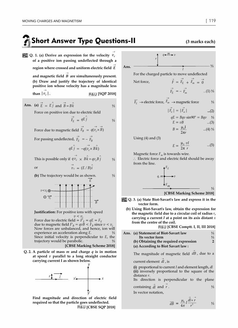
(b)
½
We have, dB→
= µπ0
34I
dI r
r
→ →
×
r2 = x2 + R2
∴ dB = µ
π0
2 2 3 24I dl
x R+( ) / ½
We need to add only the components of dB
along the axis of the coil.
Hence, B =µ
πθ0
2 2 3 24I Idl
x R. cos/
+( )∫
= µ
π0
2 2 3 24I Idl R
x R
( )+( )∫ / ½
=µ0
2
2 2 3 22
IR
x R+( ) /
∴ B→
=µ0
2
2 2 3 22
IR
x Ri
+( ) / ½
[CBSE Marking Scheme 2018]
Q. 4. Two identical loops P and Q each of radius 5 cm are lying in perpendicular planes such that they have a common centre as shown in the figure. Find the magnitude and direction of the net magnetic field at the common centre of the two coils, if they carry currents equal to 3 A and 4 A respectively.
U [O.D. II 2017]Q
P
Ans. Formula ½Field due to each coil ½ + ½Magnitude of resultant fieldDirection of resultant field ½
Field at the centre of a circular coil =µ0
2I
R ½
Field due to coil P =µ0
2
32 5 10
×× × − tesla
= 12p × 10–6 tesla ½
Field due to coil Q =µ0
2
42 5 10
×× × − tesla
= 16p × 10–6 tesla ½
Resultant Field = π µ12 162 2+( ) T
= (20p)mT 1
Let the field make an angle q with the vertical
tan q = 12 1016 10
34
6
6
ππ
××
=−
−
q = tan–1 3
4 ½
(Alternatively : q' = tan–1 43
, 'θ = angle with the
horizontal)
[Note 1 : Award 2 marks if the student directly
calculates B without calculating BP and BQ
separately.]
[Note 2 : Some students may calculate the field
BQ and state that it also represents the resultant
magnetic field (as coil P has been shown 'broken'
and therefore, cannot produce a magnetic field);
They may be given 2½ marks for their (correct)
calculation of BQ]
[CBSE Marking Scheme 2017]
Detailed Answer :Try yourself, Similar to Q. 3, Short Answer Type I
Q. 5. (i) State Biot-Savart's law and express this law in the vector form.(ii) Two identical circular coils, P and Q each of radius R, carrying currents 1 A and √3 A respectively, are placed concentrically and perpendicular to each other lying in the XY and YZ planes. Find the magnitude and direction of the net magnetic field at the centre of the coils. U [O.D. I, III 2017]
Ans. (i) Statement of Biot-Savart's law 1Expression in vector form ½
(ii) Magnitude of magnetic field at centre 1Direction of magnetic field ½
(i) It states that magnetic field strength, dB
due to a current element, Idl
at a point, having a position vector r→
relative to the current element, is found to depend (i) directly on the current element, (ii) inversely on the square
of the distance | |r
(iii) directly on the sine of angle between the current element and the position vector r→
.

https://aktecheasy.blogspot.com
120 ] Oswaal CBSE Chapterwise & Topicwise Question Bank, PHYSICS, Class – XII Moving charges and MagnetisM [ 121
In vector notation, dB
=µ
π0
34Idl r
r
×
Alternatively,
1
dBIdl r
r
= ×
µπ0
24.
(ii) BP =µ µ0 01
2 2× =R R
(along Z-direction) ½
BQ =µ µ0 03
23
2× =R R
(along X-direction) ½
\ B = B BRP Q
2 2 0+ = µ½
This net magnetic field B, is inclined to the field BP, at an angle q where tan q = 3
or θ = = °( )−tan 1 3 60
(in XZ plane) ½
[CBSE Marking Scheme 2017]OR
https://aktecheasy.blogspot.com
122 ] Oswaal CBSE Chapterwise & Topicwise Question Bank, PHYSICS, Class – XII Moving charges and MagnetisM [ 123
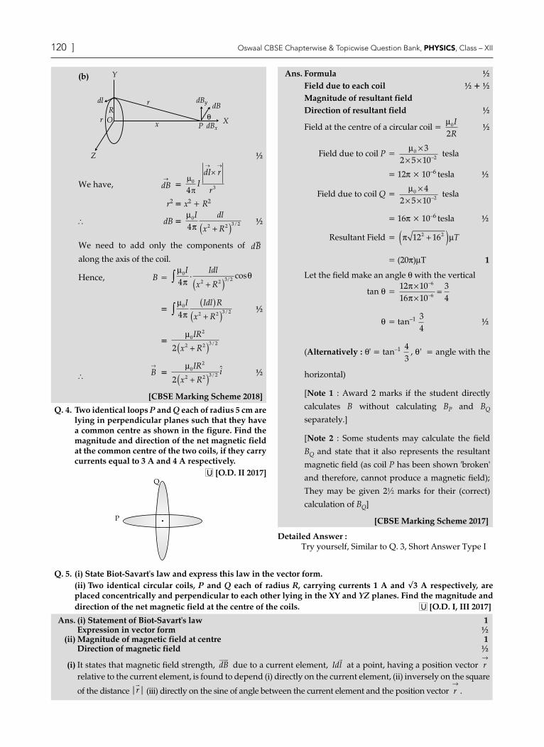
[Topper's Answer 2017]
Q. 6. Using Biot-Savart's law, deduce the expression for the magnetic field at a point (x) on the axis of a circular current carrying loop of radius R. How is the direction of the magnetic field determined at this point? U [Foreign I, II 2017]
Ans. Try yourself, Similar to Q.3 (b) of Short Answer.
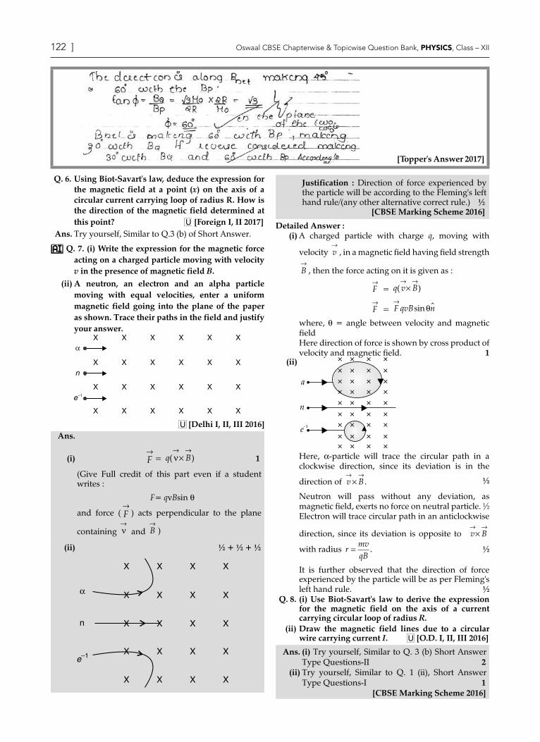
Q. 7. (i) Write the expression for the magnetic force acting on a charged particle moving with velocity v in the presence of magnetic field B.
(ii) A neutron, an electron and an alpha particle moving with equal velocities, enter a uniform magnetic field going into the plane of the paper as shown. Trace their paths in the field and justify your answer.
U [Delhi I, II, III 2016]Ans.
(i) F→
= q B( )ν→ →
× 1
(Give Full credit of this part even if a student writes :
F = qnBsin q
and force ( F→
) acts perpendicular to the plane
containing ν→
and B→
)
(ii) ½ + ½ + ½
X X X X
X X X X
X X X X
X X X X
X X X X
α
n
e–1
Justification : Direction of force experienced by the particle will be according to the Fleming's left hand rule/(any other alternative correct rule.) ½ [CBSE Marking Scheme 2016]
Detailed Answer :(i) A charged particle with charge q, moving with
velocity v→
, in a magnetic field having field strength
B→
, then the force acting on it is given as :
F→
= q v B( )→ →
×
F→
= F qvB n→
sin θ
where, q = angle between velocity and magnetic fieldHere direction of force is shown by cross product of velocity and magnetic field. 1
(ii)
a
n
e–1
Here, a-particle will trace the circular path in a clockwise direction, since its deviation is in the
direction of v B→ →
× . ½
Neutron will pass without any deviation, as magnetic field, exerts no force on neutral particle. ½Electron will trace circular path in an anticlockwise
direction, since its deviation is opposite to → →v B×
with radius rmvqB
= . ½
It is further observed that the direction of force experienced by the particle will be as per Fleming's left hand rule. ½
Q. 8. (i) Use Biot-Savart's law to derive the expression for the magnetic field on the axis of a current carrying circular loop of radius R.
(ii) Draw the magnetic field lines due to a circular wire carrying current I. U [O.D. I, II, III 2016]
Ans. (i) Try yourself, Similar to Q. 3 (b) Short Answer Type Questions-II 2
(ii) Try yourself, Similar to Q. 1 (ii), Short Answer Type Questions-I 1 [CBSE Marking Scheme 2016]

https://aktecheasy.blogspot.com
122 ] Oswaal CBSE Chapterwise & Topicwise Question Bank, PHYSICS, Class – XII Moving charges and MagnetisM [ 123
Q. 9. Consider the motion of a charged particle of mass m and charge q moving with velocity v
→in a
magnetic field B→
.
(i) If v→
is perpendicular to B→
, show that it describesa circular path having angular frequency
ω = qB/m.(ii) If the velocity v
→has a component parallel to the
magnetic field B→
, trace the path described by the particle. Justify your answer.
U [Delhi Comptt. I, II, III 2014]
Ans. (i) Force acting on the charged particle, moving
with a velocity v→
, in a magnetic field B→
:
F→
= q v B( )→ →
× ½
As, v→
⊥ B→
, F = qvB
Since, F→
⊥ v→
, it acts as a centripetal force andmakes the particle move in a circular path in the plane, perpendicular to the magnetic field. ½
∴ qvB =mv
r
2
∴ r =mvqB
or vr
qBm
=
Now ω = vr
∴ ω =qBm
½
(ii)
B
radius
pitch
q
vv
y
z
vII
½
The component of velocity v→
parallel to magnetic
field, will make the particle move along the field.
The perpendicular component of velocity v→
will cause the particle to move along a circular path in the plane perpendicular to the magnetic field.Hence, the particle will follow a helical path, as shown. [CBSE Marking Scheme, 2014] 1
Q. 10. (i) State the condition under which a charged particle moving with velocity v goes undeflected in a magnetic field B.
(ii) An electron, after being accelerated through a potential difference of 104 V, enters a uniform
magnetic field of 0·04 T, perpendicular to its direction of motion. Calculate the radius of curvature of its trajectory. U [Foreign I 2017]
Ans. (i) Condition for charge going undeflected 1(ii) Formula for radius ½
Calculation of radius 1½
(i) The force experienced, F
= q v B
×( ) ½
The charge will go undeflected when v
is parallel or antiparallel to B
F
= 0. ½
[Alternatively,If v
makes an angle of 0° or 180° with B
](ii) The KE of electron
KE =
e r Bm
eV2 2 2
2=
½
\ r =1 2B
mVe
½
= 2 9 1 10 10
1 6 101
0 04
31 4
19× × ×
××
−
−.. .
m ½
= 8.4 × 10⁻³ m
Q. 11. Write the expression for the magnetic force
F→
acting on a charged particle q moving with
velocity v→
in the presence of the magnetic field
B→
in a vector form. Show that no work is done and no change in the magnitude of the velocity of the particle is produced by this force. Hence, define the unit of magnetic field. U [Foreign 2016]
Ans. The required expression is
F→
= ( )v B→ →
× ½
The magnetic force, at all instants, is, therefore, perpendicular to the instantaneous direction of
v→
, which is also the instantaneous direction of
displacement ( )ds→
. ½
Since, F→
is perpendicular to ( )ds→
, at all instants,
work done ( · )=→ →F ds is zero. ½
There being no work done, there can be no change
in the magnitude of v→
. ½
From F→
= q ( )v B→ →
× , we get
| |F→
= F = qvBsin θ
∴ F = B if q = 1, v = 1 and θ = π2
Hence, the magnetic field, B→
at a point equals one tesla if a charge of one coulomb, moving with a velocity of 1 m/s, along a direction perpendicular
to the direction of B→
, experiences a force of one newton.

https://aktecheasy.blogspot.com
124 ] Oswaal CBSE Chapterwise & Topicwise Question Bank, PHYSICS, Class – XII Moving charges and MagnetisM [ 125
[Note : Also accept if the student just writes that
| |B→
= 1 tesla if | |F→
= one newton, for q = 1
coulomb, v = 1 m/s and θ = π2
] 1
[CBSE Marking Scheme, 2016]
Q. 12. A fine pencil of b-particles moving with a speed, enters a region (region I), where a uniform electric and a uniform magnetic fields are both present. These b-particles then move into region II where only the magnetic field, (out of the two fields present in region I), exists. The path of the b-particles in the two regions is as shown in the figure.
Sq II
I
E
+ + + + + + +
(i) State the direction of the magnetic field.(ii) State the relation between ‘E’ and ‘B’ in region I.
(iii) Derive the expression for the radius of the circular path of the b-particle in region II.If the magnitude of magnetic field in region IIis changed to n times its earlier value (without changing the magnetic field in region I), find the factor by which the radius of this circular path
would change. A&E [CBSE SQP 2013]
Ans. (i) The magnetic field is perpendicular to the plane
of paper and is directed inwards. ½
(ii) In region I :
| F→
e| = | F→
m|
qE = qvB \ E = vB ½
(iii) In region II :
mvr
2= qvB
⇒ r =mvqB
½
Substituting the value of v, we get
r = mE
qB2 ½
Let B′ (= nB) denote the new magnetic field in region II. If r′ is the radius of the circular path now, we have
r' =
mq
EB'2
= m
qnEB22
½
Hence, radius of the circular path, would decrease by a factor n2. ½
Q. 13. (i) Obtain an expression for cyclotron frequency.(ii) A deuteron and a proton are accelerated by the
cyclotron. Can both be accelerated with the same oscillator frequency ? Give reason to justify your answer. U [Delhi Set I, II, III 2017]
Ans. (i) Derivation of the expression for cyclotron frequency 2(ii) Reason/justification for the correct answer 1
(i) mv
r
2
= qvB ½
r =
mvqB
½
Frequency of revolution, u = 1
Time Period
=
vr2π =
qBm2π 1
(ii) NoThe mass of the two particles, i.e., deuteron and proton, is different.Since (cyclotron) frequency depends inversely on the mass, they cannot be accelerated by the same oscillator frequency. 1 [CBSE Marking Scheme 2017]
Detailed Answer :(i) Let a particle of charge q revolving in the path of
radius r with velocity v, so for circular motion, Centripetal force = Lorentz force (due to magnetic
field B)
mvr
2= qvB ½
Now,vr
= qBm
...(i) ½
But, angular velocity, w = vr
Hence, w = qBm
...(ii) ½
Using Time period, T = 2πω
equation (ii), can be written as,
T = 2πmqB
Cyclotron frequency, n = 1
2 2TqB
m= =ω
π π½
(ii) A cyclotron works only when the frequency of the revolution of particle is equal to the frequency of oscillation.\ Mass of proton and deuteron are different
i.e., (md = 2mp)
and v µ 1m
½
\ Frequency of revolution of proton and deuteron is different, so they can't be accelerated with same oscillator frequency. ½

https://aktecheasy.blogspot.com
124 ] Oswaal CBSE Chapterwise & Topicwise Question Bank, PHYSICS, Class – XII Moving charges and MagnetisM [ 125
Q. 14. (i) Name the machine which uses crossed electric and magnetic fields to accelerate the ions to high energies. With the help of a diagram, explain the resonance condition.
(ii) What will happen to the motion of charged particle if the frequency of the alternating voltage is doubled ? R [CBSE SQP 2016]
ORDraw a schematic sketch of a cyclotron. Explain, giving the essential details of its construction, how it is used to accelerate the charged particles. [O.D., Delhi I, II, III 2014, 2011]
Ans.
P
Magnetic field outof the paper Deflection plate
Exit Port
Chargedparticle
D2D1
OSCILLATOR 1Construction : The cyclotron is made up of two hollow semi-circular discs like metal containers, D1 and D2 called dees.It uses crossed electric and magnetic fields. The electric field is provided by an oscillator of adjustable frequency. 1Working : In a cyclotron, the frequency of the applied alternating field is adjusted to be equal to the frequency of revolution of the charged particles in the magnetic field. This ensures that the particles get accelerated every time, they cross the space between the two dees. The radius of their path increases with increase in energy and they are finally made to leave the system via an exit slit.
(ii) (a) Particle will accelerate and deaccelerate alternately. However, the radius of path remain unchanged. 1
[CBSE Marking Scheme 2011]
Q. 15. (i) Deduce an expression for the frequency of revolution of a charged particle in a magnetic field and show that it is independent of velocity or energy of the particle.
(ii) Draw a schematic sketch of a cyclotron. Explain, giving the essential details of its construction, how it is used to accelerate the charged particles.
U [O.D. I, II, III, 2014]Ans. (i) Try yourself, Similar to Q. No. 13(i), Short Answer
Type II 3(ii) Try yourself, Similar to Q. No. 14, Short Answer Type II 2
Q. 16. A circular coil, having 100 turns of wire, of radius (nearly) 20 cm each, lies in the XY plane with its centre at the origin of co-ordinates. Find the magnetic field at the point (0, 0, 20 3 cm) when
this coil carries a current of 2π
A.
A [Delhi Comptt. 2016]
Ans. The plane of coil is XY plane and field point is on
the Z-axis. ½
∴ Magnetic field on the axial point
B =µ0
2
2 2 3 22IR N
R z( ) /+1
= 4 10 2 0 2 100
2 0 2 0 2 3
7 2
2 2 3 2
ππ
× × × ×
+
− ( . )
[( . ) ( . ) ] / ½
= 8 0 04 10 1002 0 04 8 0 2
7× × ×× × ×.
. .
-½
= 25 µT ½
[CBSE Marking Scheme 2016]
Long Answer Type Questions (5 marks each)
Q. 1. (i) Derive an expression for the magnetic field at point on the axis of a current carrying circular loop.
(ii) A coil of 100 turns (tightly bound) and radius 10 cm, carries a current of 1 A. What is the magnitude of the magnetic field at the centre of the coil.
U [SQP I 2017]
Ans. (i) Derivation : 3(ii) Numerical : 2(i) Try yourself, Similar to 3 (b), Short Answer Type II
3
(ii) Since the coil is tightly bound, we may take each circular element to have the same radius R = 10 cm = 0.1 m, N=100Magnitude of magnetic field :
B = µ0
2NIR
B = 4 10 10 1
2 10
7 2
1π × × ×
×
−
−
= 2p × 10–4 1 = 6.28 × 10⁻⁴ T 1 [CBSE Marking Scheme 2017]

https://aktecheasy.blogspot.com
126 ] Oswaal CBSE Chapterwise & Topicwise Question Bank, PHYSICS, Class – XII Moving charges and MagnetisM [ 127
Q. 2. (i) Express Biot-Savart law in the vector form.(ii) Use it to obtain the expression for the magnetic field at an axial point, distance d from the centre of a
circular coil of radius R carrying current I.(iii) Also, find the ratio of the magnitudes of the magnetic field of this coil at the centre and at an axial point for
which x = R 3 . R&A [O.D. I 2016]
Ans.
[Topper's Answer 2016]
Detailed Answer :(i) Try yourself, Similar to Q. 3(a) of Short Answer Type Questions-II. 2
(ii) Try yourself, Similar to Q. 3(b) of Short Answer Type Questions-II. 3

https://aktecheasy.blogspot.com
126 ] Oswaal CBSE Chapterwise & Topicwise Question Bank, PHYSICS, Class – XII Moving charges and MagnetisM [ 127
Q. 3. (i) (a) Use Biot-Savart's law to derive the expression for the magnetic field due to a circular coil of radius R having N turns at a point on the axis at a distance ‘x’ from its centre.(b) Draw the magnetic field lines due to this coil.
(ii) A current ‘I’ enters a uniform circular loop of radius ‘R’ at point M and flows out at N as shown in the figure.Obtain the net magnetic field at the centre of the loop.
90° O
N
I
MI
U [Delhi I, II, III 2015]Ans. (i) (a) Try yourself, Similar to Q. 3 (b), Short Answer
Type Questions-II. 2(b) Try yourself, Similar to Q. 1 (ii), Short Answer Type Questions-I 1
(ii) Let current I be divided at point M into two parts I1 and I2 ; in bigger and smaller parts of the loop respectively.Magnetic field of current I1 at point O, ½
B1
→=
µπ
θ µπ
π0 1 0 1
4 4 2IR
Ir
= × ×
=µ0 1
8IR
(in the direction of B1)
½
Magnetic field due to current I2 at point O
B2
→=
µπ0 2
432
. .x I
R
=
38
0 2µ IR
(in the direction of B2)
Net magnetic field, B→
= B1
→+ B2
→
| |B
→=
µ µ0 1 0 2
8 8IR
IR
− × 3 ...(i) ½
But I1= 3I2 (As resistance of bigger part is three times that of the smaller part of the loop.)
Substituting I1=3I2 in equation (i),
| |B→
= 0 ½
TopiC-2Ampere's Circuital Law and its Applications
Revision Notes¾ Ampere’s circuital law states that the line integral of magnetic field around a closed path is µ0 times of total
current enclosed by the path, B dI I. =∫ µ0
where,
B = magnetic field
dl = infinitesimal segment of the path
µ0 = permeability of free space
I = enclosed electric current by the path
r
i
Amperian
loop
Net current passing
through the closed
Amperian loop
¾ Magnetic field at a point will not depend on the shape of Amperian loop and will remain same at every point on the loop.
Forces between two parallel currents ¾ Two parallel wires separated by distance r having currents I1 and I2 where magnetic field strength at second wire
due to current flowing in first wire is given as :
BIr
= µπ0 1
2

https://aktecheasy.blogspot.com
128 ] Oswaal CBSE Chapterwise & Topicwise Question Bank, PHYSICS, Class – XII Moving charges and MagnetisM [ 129
• In this, the field is orientated at right-angles to second wire where force per unit length on the second wire will be :
Fl
I Ir
=µ
π0 1 2
2
• Magnetic field-strength at first wire due to the current flowing in second wire will be :
BIr
= µπ0 2
2
¾ One ampere is the magnitude of current which, when flowing in each parallel wire one metre apart, results in a force between the wires as 2 × 10⁻⁷ N per meter of length.
Applications of Ampere’s law to infinitely long straight wire, straight and toroidal solenoids :(i) Magnetic Field due to long straight wire
¾ Amperes law describes the magnitude of magnetic field of a straight wire as :
BIr
= µπ0
2
l
B
l
Magnetic
field lines
×
where, • Field B is tangential to a circle of radius r centered on the wire. • Magnetic field B and path length L will remain parallel where magnetic field travels.
(ii) Magnetic Field due to Solenoid¾ Solenoid : An electromagnet that generates a controlled magnetic field.¾ Solenoid is a tightly wound helical coil of wire whose diameter is small compared to its length.¾ Magnetic field generated in the centre, or core of a current carrying solenoid is uniform and is directed along the
axis of solenoid.
¾ Magnetic field due to a straight solenoid :
• at any point in the solenoid, B = m0nI
• at the ends of solenoid, BnI
end =µ0
2where, n = number of turns per unit length, I = current in the coil.
×
L
× × × × × × ×
a b
ee
Magnetic field lines
I into paper
I out of paper
(iii) Magnetic Field due to Toroid¾ Toroid : It is an electronic component made of hollow circular ring wound with number of turns of copper wire.¾ The toroid is a hollow circular ring on which a large number of turns of a wire are closely wound.¾ A toroid with n turns per unit length with mean radius r, where current i is flowing through it, then the magnetic
field experienced by the toroid with total number of turns N will be :
B dl i→ →
∫ =. µ0 Þ B × 2pr = m0Ni where, r = average radius
Here,
BNir
ni= =µπ
µ002
here,nN
r=
2π
r
i

https://aktecheasy.blogspot.com
128 ] Oswaal CBSE Chapterwise & Topicwise Question Bank, PHYSICS, Class – XII Moving charges and MagnetisM [ 129
¾ At any point, empty space surrounded by toroid and outside the toroid, magnetic field B will be zero as net current is zero.
Key Formulae
¾ Ampere's circuital law B dl I→ →
∫ =. µ0
¾ Magnetic field at the surface of a solid cylinder : B = µπ0
2IR
¾ Magnetic field inside the solenoid : B = m0nI
¾ Magnetic field in a toroid with mean radius r : r = µ
π0
2Nir
¾ Force between two parallel current carrying wires : F = µ
π0
1 22I I L
objective Type Questions (1 mark each)
Q. 1. An electron is projected with uniform velocity along the axis of a current carrying long solenoid. Which of the following is true?
(a) The electron will be accelerated along the axis.(b) The electron path will be circular about the axis.(c) The electron will experience a force at 45° to the
axis and hence execute a helical path.(d) The electron will continue to move with uniform
velocity along the axis of the solenoid.[NCERT Exemplar]
Ans. Correct option : (d)Explanation : The magnetic field inside the long current carrying solenoid is uniform. Therefore, magnitude of force on the electron of charge (– e) is given by F = – evB sin q = 0 (q = 0°) as magnetic field and velocity are parallel. The electron will continue to move with uniform velocity along the axis of the
solenoid.Q. 2. In a cyclotron, a charged particle
(a) undergoes acceleration all the time.(b) speeds up between the dees because of the
magnetic field.(c) speeds up in a dee.(d) slows down within a dee and speeds up
between dees. [NCERT Exemplar]Ans. Correct option : (a)
Explanation : In a cyclotron, a charged particle describes the circular path inside the dees and is accelerated while going from one dee to another due to the electric field. While moving in the circular path, charged particles have centripetal acceleration which is provided by the magnetic force due to the magnetic field. A charged particle undergoes acceleration all the time, inside the cyclotron.
Short Answer Type Questions-i (2 marks each)
Q. 1. Find the condition under which the charged particles moving with different speeds in the presence of electric and magnetic field vectors can be used to select charged particles of a particular speed. R [O.D. I, II, III 2017]
Ans. (i) For directions of E B v
, , 1
(ii) For magnitudes of E B v
, , 1
(i) The velocity v
of the charged particles, and the E
and B
vectors, should be mutually perpendicular. ½
Also the forces on q, due to E
and B
must be oppositely directed. ½
(Also accept if the student draws a diagram to show the directions.)
z
x
y
v
FE
E
FB
B
(ii) qE = qvB ½
v =EB
½

https://aktecheasy.blogspot.com
130 ] Oswaal CBSE Chapterwise & Topicwise Question Bank, PHYSICS, Class – XII Moving charges and MagnetisM [ 131
[Alternatively, The student may write :Force due to electric field =
qE
½
Force due to magnetic field = q v B
×( ) ½
The required condition is
qE
= − ×( )q v B
½
or E v B B v
= − ×( ) = ×( )
½
(Note : Award 1 mark only if the student just writes :"The forces, on the charged particle, due to the electric and magnetic fields, must be equal and opposite to each other") [CBSE Marking Scheme 2017]
Detailed Answer :If a charged particle travels in crossed electric and magnetic field, then both fields are perpendicular to each other.Force on the particle will be :
F→
= F FE B
→ →+
F→
= qE q v B→ → →
+ ×( )
As FB is 180° to FE, so
F→
= qE q v B→ → →
− ×( )
F→
= q(E – vvB) j
Now to select a particle, making resultant force as zero, hence
0 = q E vB j( )−
Now, E – vB = 0 E = vB
Hence, v = EB
2
Q. 2. A particle of charge q is moving with velocity v in the presence of crossed electric field E and magnetic field B as shown. Write the condition under which, the particle will continue moving along x-axis. How would the trajectory of the particle be affected if the electric field is switched off ? R [SQP 2017-18]
z
x
y
v
E
B
Ans. Condition under which, the particle will continue moving along x-axis, qE = qvB ½
v = EB
½
Trajectory becomes helical about the direction of magnetic field. 1 [CBSE Marking Scheme 2017]
Q. 3. A charge q of mass m is moving with a velocity of v, at right angles to a uniform magnetic field B. Deduce the expression for the radius of the circular path it describes. R [Delhi Compt. I, III 2017]
Ans. Derivation of the expression for radius 2Force experienced by charged particle in magnetic field B
,
F
= q v B
×( )
½
As v and B are perpendicular, F = qvB ½This force is perpendicular to the direction of velocity and hence acts as centripetal force.
mv
r
2
= qvB ½
r =mvqB
½
[CBSE Marking Scheme 2017]
Detailed Answer :When a charged particle is given with initial velocity v in a direction perpendicular to uniform magnetic field, it will be described in a circular path as shown. If a positively charged particle located at point O is given an initial velocity v perpendicular to field, the field will exert an upward force of F = qvB at point O.
½
Q
V
PPP
R
F
F
O
×
×
×
×
×
×
×
×
×
×
×
×
×
×
×
×
×
×
×
×
×
×
×
×
×
×
×
×
×
×
×
×
×
×
×
×
×
×
×V
×
×
×
×
×
×
×
×
×
×
×
×
×
×
×
×
×
×
×
×
×
×
As the force is always at right angles to the velocity, it will not affect the magnitude of velocity, but will tends to change its direction. When the particle reaches points P and Q, then in such case, directions of force and velocity will get changed. Also, a constant centripetal force will act on the particle making the particle to move in a circle.
Now the centripetal acceleration =vR
2½
From Newton’s second law, qvBmv
R=
2½
Hence the radius of circular orbit will be :
R
mvBq
= ½
where, m = mass of particle q = charge of particle
Q. 4. A proton and an alpha particle having the same kinetic energy are, in turn, passed through a region of uniform magnetic field, acting normal to the plane of the paper and travel in circular paths. Deduce the ratio of the radii of the circular paths described by them. R [Delhi Comptt. II 2017]

https://aktecheasy.blogspot.com
130 ] Oswaal CBSE Chapterwise & Topicwise Question Bank, PHYSICS, Class – XII Moving charges and MagnetisM [ 131
Ans. Derivation of ratio of the radii of the circular paths 2
r =mvqB
But pm
2
2= k Þ p = 2mk = mv ½
Þrrp
α = 2
2
m k q B
m k q Bp p p
α α α/
/
½
But ka = kp
r
rp
a =
m
mp
pα
α
Since, qa = 2qp ½ma = 4mp ½
Þ r
rp
α
= 2
41 1
q
q
m
mp
p
p
p
= :
[CBSE Marking Scheme 2017]
Q. 5. Deduce an expression for the frequency of revolution of a charged particle in a magnetic field and show that it is independent of velocity or energy of the particle. U [O.D. I, II, III 2014]
Ans. When a particle of mass m and charge q, moves with a velocity v, in a uniform magnetic field B, it experiences a force F where
F→
= q ( )v B→ →
× ½
∴ Centripetal force,mv
r
2= qvB⊥ ½
or, r =mvqB⊥
½
∴ Frequency, f = vr2p
= qB2
⊥πm
½
Hence, it is independent of the velocity or the energy of the particle. [CBSE Marking Scheme 2014]
Q. 6. A proton and a deuteron, each moving with
velocity v→
enter simultaneously in the region of
magnetic field B→
acting normal to the direction of velocity. Trace their trajectories establishing the relationship between the two.
A [Delhi Comptt. I, II, III 2012]
Ans. Mass of proton = 1 u, mass of deuteron = 2 u
Charge of proton = e, charge of deuteron = e
Since charge is same for both particles, so
r
rp
d
= m
mp
d=
12
1
Trajectories of path are circular as given below :
2R
R
Proton
DeuteronO
1
Q. 7. Draw the magnetic field lines due to a current passing through a long solenoid. Use Ampere’s circuital law, to obtain the expression for the magnetic field due to the current I in a long solenoid having n number of turns per unit length. U [Comptt. Delhi I, II, III 2014]
Ans.
Q
P ½
Alternatively,
½
Q
P
d
Qh
c
ba
PB
https://aktecheasy.blogspot.com
132 ] Oswaal CBSE Chapterwise & Topicwise Question Bank, PHYSICS, Class – XII Moving charges and MagnetisM [ 133
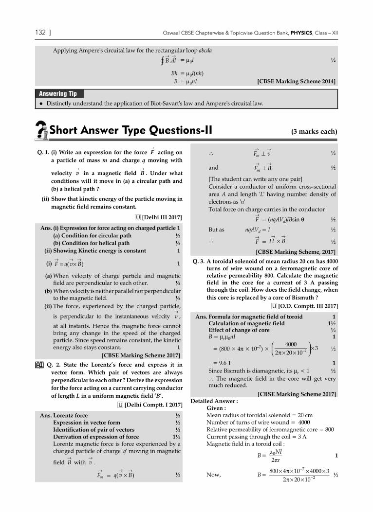
Applying Ampere's circuital law for the rectangular loop abcda
B dl→ →
∫ . = µ0I ½
Bh = µ0I(nh) B = µ0nI [CBSE Marking Scheme 2014]
Answering Tip Distinctly understand the application of Biot-Savart's law and Ampere's circuital law.
Short Answer Type Questions-ii (3 marks each)
Q. 1. (i) Write an expression for the force F→
acting on a particle of mass m and charge q moving with
velocity v→
in a magnetic field B→
. Under what conditions will it move in (a) a circular path and (b) a helical path ?
(ii) Show that kinetic energy of the particle moving in magnetic field remains constant.
U [Delhi III 2017]
Ans. (i) Expression for force acting on charged particle 1(a) Condition for circular path ½(b) Condition for helical path ½
(ii) Showing Kinetic energy is constant 1
(i) F q→
v B→ →
= ×( ) 1
(a) When velocity of charge particle and magnetic field are perpendicular to each other. ½
(b) When velocity is neither parallel nor perpendicular to the magnetic field. ½
(ii) The force, experienced by the charged particle,
is perpendicular to the instantaneous velocity v→
, at all instants. Hence the magnetic force cannot bring any change in the speed of the charged particle. Since speed remains constant, the kinetic energy also stays constant. 1 [CBSE Marking Scheme 2017]
Q. 2. State the Lorentz’s force and express it in vector form. Which pair of vectors are always perpendicular to each other ? Derive the expression for the force acting on a current carrying conductor of length L in a uniform magnetic field ‘B’.
U [Delhi Comptt. I 2017]
Ans. Lorentz force ½Expression in vector form ½Identification of pair of vectors ½Derivation of expression of force 1½Lorentz magnetic force is force experienced by a charged particle of charge 'q' moving in magnetic
field B→
with v→
.
Fm
→= q v B( )
→ →×
½
\ F vm
→ →⊥
½
and F Bm
→ →⊥
½
[The student can write any one pair]Consider a conductor of uniform cross-sectional area A and length 'L' having number density of electrons as 'n'Total force on charge carries in the conductor
F→
= (nqAVd)lBsin q ½
But as nqAVd = I ½
\ F→
= I l B→ →
× ½
[CBSE Marking Scheme, 2017]
Q. 3. A toroidal solenoid of mean radius 20 cm has 4000 turns of wire wound on a ferromagnetic core of relative permeability 800. Calculate the magnetic field in the core for a current of 3 A passing through the coil. How does the field change, when this core is replaced by a core of Bismuth ?
U [O.D. Comptt. III 2017]
Ans. Formula for magnetic field of toroid 1Calculation of magnetic field 1½Effect of change of core ½B = mrm0nI 1
= (800 × 4p × 10–7) × 4000
2 20 1032π× ×
×− ½
= 9.6 T 1Since Bismuth is diamagnetic, its mr < 1 ½\ The magnetic field in the core will get very much reduced.
[CBSE Marking Scheme 2017]Detailed Answer :
Given :Mean radius of toroidal solenoid = 20 cmNumber of turns of wire wound = 4000Relative permeability of ferromagnetic core = 800Current passing through the coil = 3 AMagnetic field in a toroid coil :
B = µ
π0
2NIr
1
Now, B =800 4 10 4000 3
2 20 10
7
2× × × ×
× ×
−
−ππ
½

https://aktecheasy.blogspot.com
132 ] Oswaal CBSE Chapterwise & Topicwise Question Bank, PHYSICS, Class – XII Moving charges and MagnetisM [ 133
B = 9.6 T 1It is observed that as Bismuth is diamagnetic substance with relative permeability less than 1, it will have a tendency to move away from the stronger to weak part of external magnetic field making the core field less as compared to empty core field. ½
Q. 4. (i) State Ampere’s circuital law, expressing it in the integral form.
(ii) Two long co-axial insulated solenoids, S1 and S2of equal lengths are wound one over the other as shown in the figure. A steady current “I” flows through the inner solenoid S1 to the other end B, which is connected to the other solenoid S2 through which the same current “I” flows in the opposite direction so as to come out at end A. If n1 and n2 are the number of turns per unit length, find the magnitude and direction of the net magnetic field at a point (i) inside on the axis and (ii) outside the combined system. U [Delhi I, II, III 2014]
A
Br2
l
S2
r1 S1
n1 turns
n2 turns
Ans. (i) Ampere’s circuital law : The line integral of the magnetic field around a closed path is µ0 times of total current enclosed by the path.
B dl→ →
∫ . = µ0I 1
(Award 1 mark if the student just writes the integral form of Ampere’s circuital law)
(ii) (a) B = µ0nIMagnitude of net magnetic field inside the combined system on the axis,
B = B1 – B2
⇒ B = µ0(n1 – n2)I 1Also accept if the student writes B = µ0(n2 – n1)I
(b) Outside the combined system, the net magnet-ic field is zero. 1
[CBSE Marking Scheme 2014]
Q. 5. Describe the concept used for the selection of velocity of a charged particle. Explain the principle of the device with the help of a diagram where the same concept is used. What is the resonating condition for the said device ? U [CBSE SQP, 2016]
Ans. EB
= u when E, u and B are perpendicular to each
other. 1
Cyclotron, E is perpendicular to B is perpendicular to u, In presence of E parabolic path and in presence of B circular path. T and u are independent of radius of the path. 1When frequency of oscillator is same as frequency of cyclotron then resonance occurs. 1 [CBSE Marking Scheme, 2016]
Detailed Answer :(i) Velocity selection : Try yourself, Similar to Q. 1,
Short Answer Type Questions-I.(ii) From the expression qE = qvB, velocity selects those
particles with speed v that pass undeflected through mutually perpendicular electric and magnetic fields where magnetic force exerted on particles moving at speeds more than this will be stronger than electric force making the particles to deflect upward while speed less than this gets deflected downward.
~volta
ge source
dee
dee
B
Z
2The resonating conditions in cyclotron occurs when frequency of applied voltage is kept exactly same as frequency of revolution of proton, then every time the proton reaches the gap between the two dees and makes the electric field reversed thereby receiving a push and resulting in very high energy.
1Q. 6. A long straight wire, of circular cross-section
(radius = a) carries a current I which is uniformly distributed across the cross-section of the wire.
Use Ampere's circuital law to calculate magnetic field B (r), due to this wire, at a point distance r < aand r > a from its axis. Draw a graph Showing the dependence of B (r) on r. U [Foreign 2016]
Ans. As per Ampere's circuital law : B→ →
∫ .dl = µ0I ½
(i) For r < aIe = current enclosed by Amperian circuital loop of radius r
= I.ππ
ra
Ira
2
2
2
2= ½
∴ B dl→
∫ = µ0.Ie =µ0
2
2Ir
a½
Or B = µ
π0
2
21
2I
r
a r·
= µ
π0
22Ira
½
(ii) For r > a
B dl→ →
∫ . = µ0I
∴ B.2πr = µ0I

https://aktecheasy.blogspot.com
134 ] Oswaal CBSE Chapterwise & Topicwise Question Bank, PHYSICS, Class – XII Moving charges and MagnetisM [ 135
or B = µ
π0
2Ir
½
The graph of, B (r) Vs. r, is as shown
Bµ r
B
ra
B
1/
µr
½ [CBSE Marking Scheme 2016]
Q. 7. (i) How is a toroid different from a solenoid ?
(ii) Use Ampere’s circuital law to obtain the magnetic field inside a toroid.
(iii) Show that in an ideal toroid, the magnetic field (a) inside the toroid and (b) outside the toroid at any point in the open space is zero.
U [O.D. Comptt. I, II, III 2014]
Ans. (i) A toroid can be viewed as a solenoid which has been bent into a circular shape to close on itself. 1
(ii)
I
P
QB
½
Q
.... .
. . . ...
.
3 Pr1O
12
r3
r2
.
S
For the magnetic field at a point S inside a toroid we have B(2pr) = µ0NI
B = µ
π0 2NI
r= µ0nI
(n = no. of turns per unit length of solenoid) ½
n = N
r2π(iii) For the loop 1, Ampere’s circuital law gives ½
B1.2pr1 = µ0(0), i.e. B1 = 0Thus the magnetic field, in the open space inside the toroid is zero.Also at point Q, we have B3 (2pr3) = µ0(Ienclosed)
But from the section cut, we see that the current coming out of the plane of the paper, is cancelled exactly by the current going into it.Hence, Ienclosed = 0∴ B3 = 0 ½ [CBSE Marking Scheme 2014]
Answering Tips Practice the derivation of Ampere's Circuital Law to
obtain the magnetic field inside a toroid.Q. 8. (a) Define SI unit of current in terms of the force
between two parallel current carrying conductors.(b) Two long straight parallel conductors carrying
steady currents Ia and Ib along the same direction are separated by a distance d. How does one explain the force of attraction between them ? If a third conductor carrying a current Ic in the opposite direction is placed just in the middle of these conductors, find the resultant force acting on the third conductor. R&U[CBSE Comptt. I, II, III 2018]
Sol. (a) Definition of SI unit of current 1(b) Explanation of the force of attraction ½Finding the resultant force acting on the third conductor 1½
(a) One ampere is the value of that steady current which, when maintained in each of the two very long, straight, parallel conductors of negligible cross-section, and placed one metre apart in vacuum, would produce on each of these conductors a force equal to 2 × 10⁻⁷ newton per metre of length. 1
(b) The wire (b) experiences a force due to the magnetic field caused by the current flowing in wire (a).
d
b
a
F1
B1
I1
I1
L
The magnetic field at any point on the wire (b) due to the current in wire (a) is perpendicular to the plane of two wires and pointing inwards and hence force on it will be towards wire (a). Similarly force on wire (a) will be towards wire (b). Hence two wires carrying currents in same direction attract each other. ½Force on wire (3) due to wire (1)
= µ
π
0
22
I Id
a c
towards right ½
Force on wire 3 due to wire 2
½µ
π
0
22
I Id
b c
towards left

https://aktecheasy.blogspot.com
134 ] Oswaal CBSE Chapterwise & Topicwise Question Bank, PHYSICS, Class – XII Moving charges and MagnetisM [ 135
Net force on wire 3
= µπ
0Id
I Ica b−[ ]
towards right ½
Also accept
= µπ
0Id
I Icb a−[ ]
towards left
Note: please do not deduct last 1/2 mark if the student does not write the direction of force.
[CBSE Marking Scheme 2018]
Q. 9. A horizontal wire AB of length l and mass m carries a steady current I1, free to move in vertical plane is in equilibrium at a height of h over another parallel long wire CD carrying a steady current I2, which is fixed in a horizontal plane. Derive an expression for force acting per unit length on the wire AB and write the conditions for which wire AB is in equilibrium ?
U [CBSE SQP 2017-18]
A B
C D
h
I2
I1
Ans. AB and CD are two parallel wires, so when the current flows in similar direction, both the wires will attract and when the current in one wire flows in opposite direction, they repel.
Now consider the above diagram, if wire AB is steady, then weight per unit length will be equal to force per unit length, so
Weight per unit length = mgl
1
Further, the restoring force /length = µ
π0 1 2
42× I I
h 1
At equilibrium, magnetic force per unit length will
be mass per unit length × g, so Fml
gI I
h= = µ
π0 1 2
2[CBSE Marking Scheme 2017] 1
Q. 10. The figure shows three infinitely long straight
parallel current carrying conductors. Find the
(i) magnitude and direction of the net magnetic field
at point A lying on conductor 1,
(ii) magnetic force on conductor 2.
U [Foreign I, II, III, 2017]
Ans. (i) Magnitude of magnetic field at A 1Direction of magnetic field at A ½
(ii) Magnitude of magnetic force on conductor 2 1Direction of magnitude force on conductor 2 ½
(i) B2= µ
π0
42 3( )I
r =
µπ0
46Ir
into the plane of the
paper/(Ä)
B3= µ
π0
42 4
3I
r( )
=
µπ0
483
Ir
out of the plane of the
paper/(·)
BA= B2 – B3 into the paper
= µ
π0
4103
Ir
into the paper/(Ä)
(ii) F21 =µ
π0
42 3I I
r( ) away from wire 1 (towards 3)
F23 = µ
π0
42 3 4
2× ×( ) ( )I I
raway from 3 (towards 1)
Fnet = F23 – F21 towards wire 1
= µ
π0
2
46( )I
r towards wire 1 3
[CBSE Marking Scheme 2017]
Q. 11. Two long straight parallel conductors carry steady
current I1 and I2 separated by a distance d. If the
currents are flowing in the same direction, show how
the magnetic field set up in one produces an attractive
force on the other. Obtain the expression for this force.
Hence define one ampere. A [Delhi I, II, III 2015]
Ans. Fab = Force experienced by wire 'a' of length 'l' due
to magnetic field of wire 'b'.
Fba = Force experienced by wire 'b' of length 'l' due to
magnetic field of wire 'a'.
Ba = Magnetic field due to wire 'a'.Bb = Magnetic field due to wire 'b'.
Ba =
µπ0 1
2Id
since
F→
= i l B( )→ →
×
Fba = I l
Id1
0 2
2.
µπ
½
Similarly,
Fab = I l
Id1
0 2
2.
µπ
½

https://aktecheasy.blogspot.com
136 ] Oswaal CBSE Chapterwise & Topicwise Question Bank, PHYSICS, Class – XII Moving charges and MagnetisM [ 137
Ia
Ib
a
b
d
l
Ba
Fba
Bb
Fab
The direction of force experienced by the wire 'a' is toward the wire 'b'. (As shown in the diagram). 1Similarly the direction of force experienced by the wire 'b' is toward the wire 'a'. Thus, the force is attractive.If two long wires are placed in vacuum at a separation of 1 m, one Ampere would be defined as the current in each wire that would produce a force of 2 × 10⁻⁷ Nm–1 per unit length of wire. 1
Q. 12. (i) Two long straight parallel conductors ‘a’ and ‘b’, carrying steady currents Ia and Ib are separated by a distance d. Write the magnitude and direction of the magnetic field produced by the conductor ‘a’ at the points along the conductor ‘b’. If the currents are flowing in the same direction, what is the nature and magnitude of the force between the two conductors ?
(ii) Show with the help of a diagram how the force between the two conductors would change when the currents in them, flow in the opposite directions. U [Foreign 2014]
Ans. (i) The magnitude of magnetic field produced by conductor ‘a’ at a point on the conductor b.
B =
µπ0
2Ida ½
The direction of magnetic field will be inward / outward perpendicular to the plane of the two conductors, depending on the direction of flow of current in conductor ‘a’. ½
Force per unit length, Fl
=µ
π0
2I I
da b ½
Nature : attractive ½(ii)
Ba
IbIa
Fab
Bb BaFba
d
Ia Ib
Bb BaFba
Fab
d
Ba
(Any one of the diagram) 1 [CBSE Marking Scheme, 2014]
Q. 13. A rectangular loop of wire of size 4 cm × 10 cm carries a steady current of 2 A. A straight long wire carrying 5 A current is kept near the loop as shown. If the loop and the wire are coplanar, find :
(i) the torque acting on the loop and(ii) the magnitude and direction of the force on the
loop due to the current carrying wire.
2 A 2 A
4 cm
1 cm
10 cm
I = 5 A
A [Delhi I, II, III 2012]
Ans. (i) Torque on the loop ½ τ = MBsin θAs M and B are parallel, θ = 0Therefore, τ = 0 ½
(ii) Force acting on the loop
|F| =
µπ
0 1 2
1 221 1I I
lr r
−
= 2 × 10–7 × 2 × 2 × 10–11
101
5 102 2- --×
N ½
=
8 1010
115
8
2×
-
- - N
= 8 10
45
6×
- N ½
= 6.4 × 10⁻⁶ N ½Direction : Towards conductor / Attractive. ½ [CBSE Marking Scheme 2012]
Q. 14. Two long straight parallel conductors carrying steady currents I1 and I2 are separated by a distance ‘d’. Explain briefly, with the help of a suitable diagram, how the magnetic field due to one conductor acts on the other. Hence deduce the expression for the force acting between the two conductors. Mention the nature of this force.
U [O.D. I, II, III 2012, 11]
Ans. Try yourself, Similar to Q. 12, Short Answer Type II 2The nature of the force is repulsive for currents in opposite direction and attractive when currents flow in the same direction. 1 [CBSE Marking Scheme 2011-12]
Q. 15. The magnitude F of the force between two straight parallel current carrying conductors kept at a distance d apart in air is given by
F =
µπ0 1 2
2. I I
d
https://aktecheasy.blogspot.com
136 ] Oswaal CBSE Chapterwise & Topicwise Question Bank, PHYSICS, Class – XII Moving charges and MagnetisM [ 137
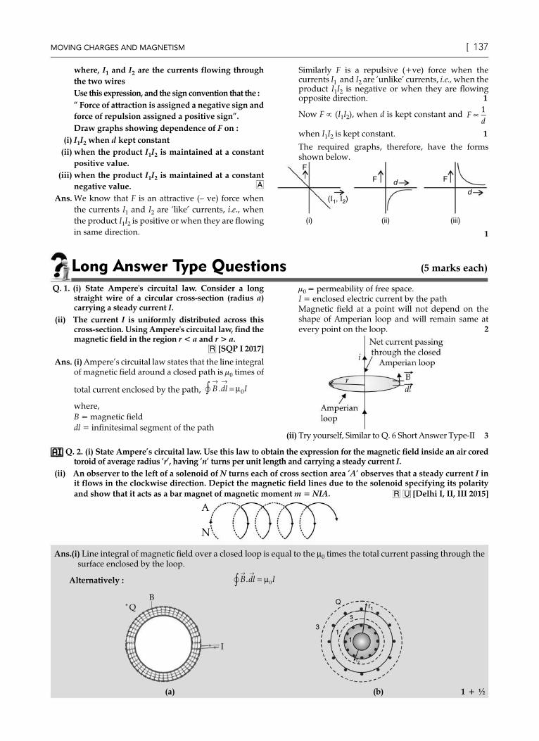
where, I1 and I2 are the currents flowing through the two wiresUse this expression, and the sign convention that the :“ Force of attraction is assigned a negative sign and force of repulsion assigned a positive sign”.Draw graphs showing dependence of F on :
(i) I1I2 when d kept constant(ii) when the product I1I2 is maintained at a constant
positive value.(iii) when the product I1I2 is maintained at a constant
negative value. A
Ans. We know that F is an attractive (– ve) force when the currents I1 and I2 are ‘like’ currents, i.e., when the product I1I2 is positive or when they are flowing in same direction.
Similarly F is a repulsive (+ve) force when the currents I1 and I2 are ‘unlike’ currents, i.e., when the product I1I2 is negative or when they are flowing opposite direction. 1
Now F ∝ (I1I2), when d is kept constant and Fd
∝1
when I1I2 is kept constant. 1
The required graphs, therefore, have the forms shown below.F
(i)
( , )1 II 2
F
(ii) (iii)
d F
d
1
Long Answer Type Questions (5 marks each)
Q. 1. (i) State Ampere's circuital law. Consider a long straight wire of a circular cross-section (radius a) carrying a steady current I.
(ii) The current I is uniformly distributed across this cross-section. Using Ampere's circuital law, find the magnetic field in the region r < a and r > a.
R [SQP I 2017]
Ans. (i) Ampere’s circuital law states that the line integral of magnetic field around a closed path is µ0 times of
total current enclosed by the path, B dl I→ →
=∫ . µ0where,B = magnetic fielddl = infinitesimal segment of the path
µ0 = permeability of free space.I = enclosed electric current by the pathMagnetic field at a point will not depend on the shape of Amperian loop and will remain same at every point on the loop. 2
(ii) Try yourself, Similar to Q. 6 Short Answer Type-II 3
Q. 2. (i) State Ampere’s circuital law. Use this law to obtain the expression for the magnetic field inside an air cored toroid of average radius ‘r‘, having ‘n‘ turns per unit length and carrying a steady current I.
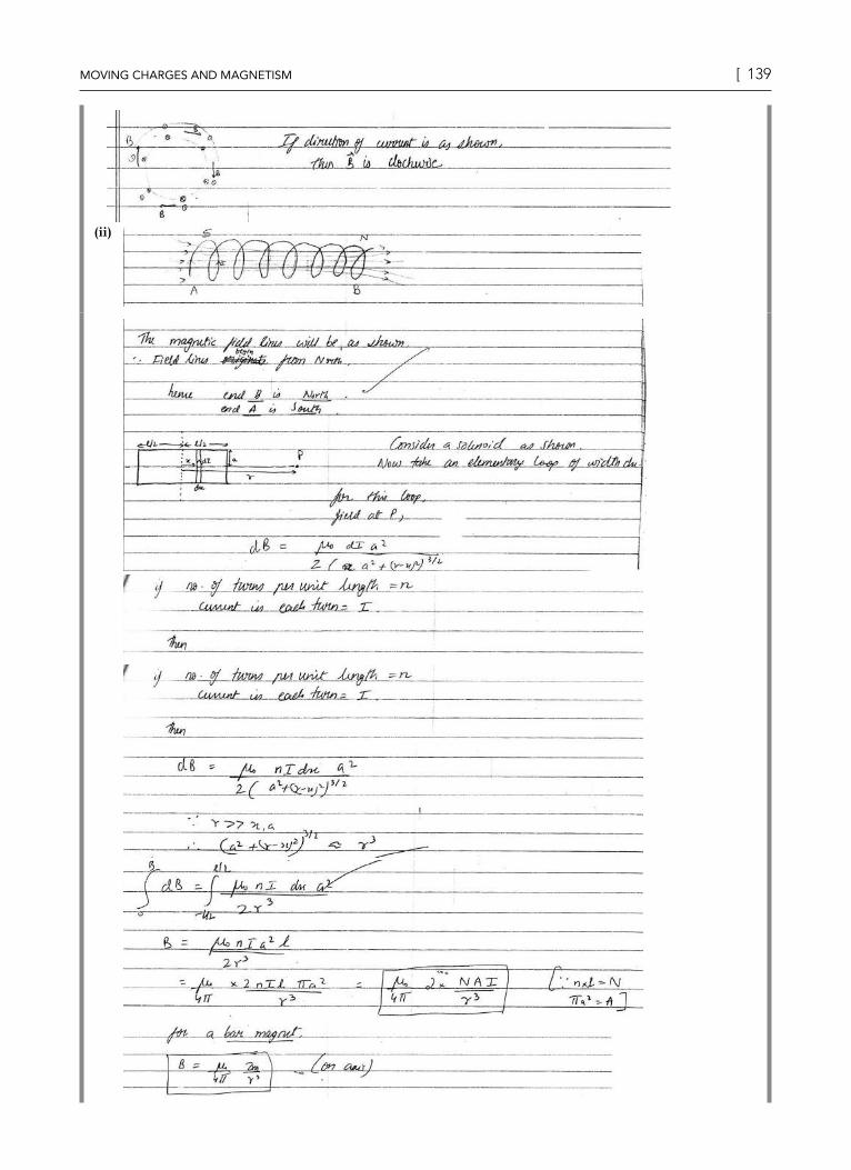
(ii) An observer to the left of a solenoid of N turns each of cross section area ‘A‘ observes that a steady current I in it flows in the clockwise direction. Depict the magnetic field lines due to the solenoid specifying its polarity and show that it acts as a bar magnet of magnetic moment m = NIA. R U [Delhi I, II, III 2015]
A
N
Ans. (i) Line integral of magnetic field over a closed loop is equal to the m0 times the total current passing through the surface enclosed by the loop.
Alternatively : B dl I→ →
=∫ . µ0
QB
I
.
Q
3
r1
s
1
r2
1
(a) (b) 1 + ½

https://aktecheasy.blogspot.com
138 ] Oswaal CBSE Chapterwise & Topicwise Question Bank, PHYSICS, Class – XII Moving charges and MagnetisM [ 139
Let the current flowing through each turn of the toroid be I. The total number of turns equals n.(2πr) where, nis the number of turns per unit length. ½Applying Ampere's circuital law, for the Amperian loop, for interior points.
B→ →
∫ .dl = µ0 (n.2πrI)
½
⇒ B × 2πr = m0n 2πrI∴ B = m0nI ½
(ii)
½ + ½
The solenoid contains N loops, each carrying a current I. Therefore, each loop acts as a magnetic dipole. The magnetic moment for a current I, flowing in loop of area (vector) A is given by
m = IA ½The magnetic moments of all loops are aligned along the same direction. Hence, net magnetic moment equals to NIA. ½
[CBSE Marking Scheme 2015]
OR
Ans. (i)
https://aktecheasy.blogspot.com
138 ] Oswaal CBSE Chapterwise & Topicwise Question Bank, PHYSICS, Class – XII Moving charges and MagnetisM [ 139
(ii)

https://aktecheasy.blogspot.com
140 ] Oswaal CBSE Chapterwise & Topicwise Question Bank, PHYSICS, Class – XII Moving charges and MagnetisM [ 141
[Topper's Answer 2015]
Q. 3. (i) Show how Biot-Savart's law can be alternatively expressed in the form of Ampere’s circuital law. Use this law to obtain the expression for the magnetic field inside a solenoid of length ‘l’, cross-sectional area ‘A’ having ‘N’ closely wound turns and carrying a steady current ‘I’.Draw the magnetic field lines of a finite solenoid carrying current I.
(ii) A straight horizontal conducting rod of length 0.45 m and mass 60 g is suspended by two vertical wires at its ends. A current of 5.0 A is set up in the rod through the wires.Find the magnitude and direction of the magnetic field which should be set up in order that the tension in the wire is zero.
U A [Delhi I, II, III 2015]Ans. (i) A current carrying surface with small line
elements of length dl where tangential components of magnetic field and sum of elements B.dl in an integral form be expressed as :
B dl→ →
∫ . = µ0i,
This form is known as Ampere’s circuital law. ½
d
Qh
c
ba
PB
½Let ‘n’ be the number of turns per unit length. Then total number of turns in the length ‘h’ is nh. Hence, total enclosed current = nhI
Using Ampere’s circuital law
B dl→ →
∫ . = µ0nhI
Bh = µ0nhI B = µ0nI ½
(ii)
Q
P
1
l
TI Bl
T
mg
As per the given figure, magnetic field must be vertically inwards, to make tension zero, (If a student shows current in opposite direction the magnetic field should be set up vertically upwards). ½ IlB = mg ½For tension to be zero ,
½
B = mg
lI=
60 10 9 85 0 0 45
3× ××
- .. .
T ½
= 0.26 T ½
TopiC-3Torque and Galvanometer
Revision NotesTorque experienced by a current loop in uniform magnetic field¾ In a rectangular loop of length l, breadth b with current I flowing through it in a uniform magnetic field of induction B
where angle q is between the normal and in direction of magnetic field, then the torque experienced will be :t = nBIAsin q
where, n = number of turns in the coil

https://aktecheasy.blogspot.com
140 ] Oswaal CBSE Chapterwise & Topicwise Question Bank, PHYSICS, Class – XII Moving charges and MagnetisM [ 141
\ nIA= mFurther, t = mBsin q
F2
F4
S
B
B
P
I
n
F1
F3
B
B
R
n
Q
¾ Torque will be maximum when the coil is parallel to magnetic field and will be zero when coil is perpendicular to magnetic field.
¾ In vector notation, torque τ→
experienced will be τ→ → →
= ×m B
Moving coil galvanometer¾ It is an instrument used for detection and measurement of small electric currents.¾ In this, when a current carrying coil is suspended in uniform magnetic field, it experiences a torque which rotates
the coil.¾ The force experienced by each side of the galvanometer will be F = BIl which are opposite in direction.
¾ Opposite and equal forces form the couple which generates deflecting torque on the coil having number of turns n is given as :
t = F × b= nBIl × b= nBIA
SP
B
F
RQ
F
I
P
F
Sb
F
¾ In moving coil galvanometer, current in the coil will be directly proportional to the angle of the deflection of the coil, I µ qi.e., where, q is the angle of deflection.
Current sensitivity of galvanometer ¾ Current sensitivity of galvanometer is the deflection produced when unit current passes through the galvanometer.
A galvanometer is said to be sensitive if it produces large deflection for a small current.
I = C
nBAθ
Current Sensitivity, θI
= nBA
C¾ Voltage sensitivity of galvanometer is the deflection per unit voltage given as
Voltage Sensitivity, θV
= θ
IGnBACG
=

https://aktecheasy.blogspot.com
142 ] Oswaal CBSE Chapterwise & Topicwise Question Bank, PHYSICS, Class – XII Moving charges and MagnetisM [ 143
where, G = galvanometer resistance, C = torsional constant. ¾ Increase in sensitivity of moving coil galvanometer depends on :
(i) number of turns n (ii) magnetic field B (iii) area of coil A and (iv) torsional constant.Conversion of galvanometer into ammeter ¾ Galvanometer can be converted into ammeter by connecting a low resistance known as shunt in parallel with the
galvanometer coil.¾ If Ig being the maximum current with full scale deflection that passes through galvanometer, then current through
shunt resistance will be is = (i – ig) where, G = Galvanometer resistance, S = Shunt resistance and i = Current in circuit
¾ Now effective resistance of ammeter will be :1
Ra =
1 1G S
+
Ra = GS
G S+Conversion of galvanometer into voltmeter¾ Voltmeter measures the potential difference between the two ends of a current carrying conductor.¾ Galvanometer can be converted to voltmeter by connecting high resistance in series with galvanometer coil. ¾ As resistance R is connected in series with galvanometer, current through the galvanometer will be,
iV
R GR
Vi
Ggg
=+
= −or,
¾ Effective resistance of voltmeter is Rv = G + R, where, Rv is very large making the voltmeter to connect in parallel since it can draw less current from the circuit.
Key Formulae ¾ Force between two parallel wires F =
µπ0 1 2
42
× ×i ia
l
¾ Force between two moving charge particle Fm = µ
π0 1 2 1 2
24× q q v v
r
¾ tmax = NBiA
¾ Current Sensitivity = θI
nABC
=
¾ Voltage Sensitivity = θV
nABCG
=
Very Short Answer Type Questions (1 mark each)
Q. 1. A multi-range voltmeter can be constructed by using the galvanometer circuit as shown. We want to construct a voltmeter that can measure 2 V, 20 Vand 200 V using a galvanometer of resistance 10 Wand that produces maximum deflection for current of 1 mA. Find R1, R2 and R3 that have to be used.
G
R1
R2
R3
2 V 20 V200 V
R [CBSE SQP 2017-18]

https://aktecheasy.blogspot.com
142 ] Oswaal CBSE Chapterwise & Topicwise Question Bank, PHYSICS, Class – XII Moving charges and MagnetisM [ 143
Ans. iG(G+ R1) = 2, R1 = 1·99 kW » 2 kWfor 2 V range
iG(G + R1 + R2) = 20, R2 = 18 kW for 20 V range
iG(G + R1 + R2+ R3) = 200, R3 = 180 k W for 200 V range 1
[CBSE Marking Scheme, 2017]
Detailed Answer :From the question, G = 10 Ω, iG = 1 mA = 10–3 AFor 2 V range, iG(G + R1) = 2, R1 = 1·99 kW » 2 kWFor 20 V range, iG (G + R1+ R2) = 20 R2 = 18 kΩFor 200 V range, iG (G + R1+ R2 + R3) = 200 R3 = 180 kΩ 1
Answering Tips Sometimes students commit errors while
substituting the values.
Q. 2. Using the concept of force between two infinitely long parallel current carrying conductors, define one ampere of current. R [O.D. I, II, III 2014]
Ans. Definition : One ampere is the value of steady current which when maintained in each of the two very long, straight, parallel conductors of negligible cross-section and placed one metre apart in vacuum, would produce on each of these conductors a force equal to 2 × 10⁻⁷ N/m of its length. 1
Alternatively :
F =µ2π
0 I Ir
L1 2
and says that whenI1= I2 = 1 amperer = 1 metre and L = 1 metre, then F = 2 × 10⁻⁷ NAlternatively,
F = 2 × 10 N–7
F = 2 × 10 N–7
1 A1 A
1 A1 A
[CBSE Marking Scheme, 2014]
Answering Tips Read the question carefully and substitute
appropriate values.
Short Answer Type Questions-I (2 marks each)
Q. 1. (i) What is the importance of a radial magnetic field and how is it produced ?
(ii) Why is it that while using a moving coil galvanometer as a voltmeter a high resistance in series is required whereas in an ammeter a shunt is used ? U [Delhi Comptt. I, II, III 2013]
Ans. (i) Importance and production of radial magnetic field : In a radial magnetic field, magnetic torque remains maximum everywhere. ½ + ½It is produced by cylindrical pole pieces and soft iron core.
(ii) Voltmeter : A high resistance in series is required when moving coil galvanometer is used as voltmeter to make sure that a low current should travel through voltmeter without changing the potential difference then needs to be measured. ½Ammeter : A shunt is used when a moving coil galvanometer is used as ammeter as to make sure about not much change in total resistance of the circuit with actual current value of flowing current. ½
Q. 2. Explain giving reasons, the basic difference in converting a galvanometer into (i) a voltmeter and (ii) an ammeter. U [O.D. I, II, III 2012]
Ans. (i) Try yourself, Similar to Q. 1, (ii) Short Answer Type Questions-I 2
[CBSE Marking Scheme 2012]
Q. 3. A square loop of side 20 cm carrying current of 1 A is kept near an infinite long straight wire carrying a current of 2 A in the same plane as shown in the figure.
20cm
20cm
10cm1 A
2 A
A B
CD
Calculate the magnitude and direction of the net force exerted on the loop due to the current carrying conductor. A [O.D. I, II, III 2015]
ORA square shaped plane coil of area 100 cm2 of 200 turns carries a steady current of 5 A. It is placed in a uniform magnetic field of 0.2 T acting perpendicular to the plane of the coil. Calculate the torque on the coil when its plane makes an angle of 60° with the direction of the field. In which orientation will the coil be in stable equilibrium ?

https://aktecheasy.blogspot.com
144 ] Oswaal CBSE Chapterwise & Topicwise Question Bank, PHYSICS, Class – XII Moving charges and MagnetisM [ 145
Ans.
30 cm
10 cma
1 A
20 cm
20 cm
b
cd
2 A
Here, I1 = 2 A; I2=1 A d1 = 10 cm; d2=30 cm µ0 = 4π × 10–7 TmA–1 We have
F =µ
π0 1 2
2I I
dl ½
∴ Net force on sides ab and cd
=µ
π0 2×12
20 101
10 101
30 102
2 2× ×× ×
-- -- N ½
= 4 × 10–7 ×20 20
10 30×
N
= 163
× 10–7 N
= 5.33 × 10⁻⁷ NThis net force is directed towards the infinitely long straight wire. ½Net force on sides bc and da = zero.
∴ Net force on the loop = 5.33×10⁻⁷ N ½ The force is directed towards the infinitely long straight wire.
OR
Torque = µm
→× B
→½
| |µm
→= nI × A = 200 × 5 × 100 × 10–4 A.m2
= 10 A.m2
Angle between µm
→and B
→= 90° – 60° = 30° ½
∴ |Torque| = 10 × 0.2 × sin 30° ½ = 1 N.m ½
Q. 4. An ammeter of resistance 0.80 Ω can measure current up to 1.0 A.
(i) What must be the value of shunt resistance to enable the ammeter to measure current up to 5.0 A ?
(ii) What is the combined resistance of the ammeter and the shunt ? A [Delhi I, II, III 2013]
Ans. (i) Shunt, S =R i
i iA g
g-
½
=
0 8 1 05 0 1 0
. .
. .×-
= 0.2 Ω ½
(ii) Combined resistance of ammeter and shunt
1Rtotal
= 1 1R SA
+ ½
= 1 1
0.8 0.2+
Rtotal =
0 85.
⇒ Rtotal = 0.16 Ω ½ [CBSE Marking Scheme, 2013]
Short Answer Type Questions-ii (3 marks each)
Q. 1. A bar magnet of magnetic moment 6 J/T is aligned at 60° with a uniform external magnetic field of 0.44 T. Calculate (a) the work done in turning the magnet to align its magnetic moment (i) normal to the magnetic field, (ii) opposite to the magnetic field, and (b) the torque on the magnet in the final orientation in case (ii). R&U
Ans. (a) Formula and Calculation of work done in the two cases
(1+ 1)(b) Calculation of torque in case (ii) 1
(a) Work done = mB(cos q1− cos q2)(i) q1 = 60°, q2 = 90°\ work done = mB(cos 60°− cos 90°)
= mB mB12
012
−
= ½
= 12
6 0 44 1 32× × =· ·J J ½
(ii) q1 = 60°, q2 = 180°\ work done = mB(cos 60° – cos 180°)
= mB mB12
132
− − =( ) ½
= 32
6 0 44 3 96× × =· ·J J ½
[Also accept calculations done through changes in potential energy.]
(b) Torque = m B mB
× = sinθ
For q = 180°, we have ½Torque = 6×0.44 sin 180° = 0
[If the student straight away writes that the torque is zero since magnetic moment and magnetic field are anti parallel in this orientation, award full marks] ½
[CBSE Marking Scheme 2018]
Q. 2. An electron of mass me revolves around a nucleus of charge + Ze. Show that it behaves like a tiny magnetic dipole. Hence, prove that the magnetic moment associated with it is expressed
as µ→ →
= − em
Le2
, where L→
is the orbital angular
momentum of the electron. Give the significance of negative sign. U [Delhi II 2017]

https://aktecheasy.blogspot.com
144 ] Oswaal CBSE Chapterwise & Topicwise Question Bank, PHYSICS, Class – XII Moving charges and MagnetisM [ 145
Ans. (i) Behaviour of revolving electron as a tiny magnetic dipole. 1
(ii) Proof of the relation, m→ →
−=em
Le2
1½
(iii) Significance of negative sign ½Electron, in circular motion around the nucleus constitutes a current loop which behaves like a magnetic dipole. 1Current associated with the revolving electron
I = eT
and T = 2πrv
\ I = −e
rv
2π ½
e–
r
+Ze
Magnetic moment of the loop, m = IA
m = IA = −ev
rr
22
ππ
=
− = −evr e m vrm
e
e2 2.
½
Orbital angular momentum of the electron,
L = – mevr
µ→
=− →em
Le2
½
–ve sign signifies that the angular momentum of the revolving electron is opposite in direction to the magnetic moment associated with it. ½
[CBSE Marking Scheme 2017]
Q. 3. Define the term current sensitivity of a galvanometer. In the circuits shown in the figures, the galvanometer shows no deflection in each case. Find the ratio of R1 and R2.
G
3 V
6 4
4 R1
6 12
8
3 V
R2
G
U [O.D. Comptt I, III 2017]
Ans. Definition of current sensitivity 1
Ratio RR
1
2
2
Current sensitivity of a galvanometer is deflection per unit current
[Alternatively, Is = θI
NABK
= ] 1
In circuit (i), 46
= R1
4 Þ R1 = 8
3 W ½
In circuit (ii), 6
2R =
128
Þ R2 = 4 W ½
\ RR
1
2 =
23
1
[CBSE Marking Scheme 2017]
Detailed Answer :(i) Current sensitivity of galvanometer is the deflection
produced when unit current passes through the galvanometer. A galvanometer is said to be sensitive if it produces large deflection for a small current.
I = C
nBAθ
where, C is torsional constant. 1
Current sensitivity = θI
= nBA
C (ii) Consider the circuit I :
For balanced Wheatstone bridge, there will be no deflection in the galvanometer, so
4
1R = 64
Hence, R1 = 4 4
683
× = Ω ½
Consider the circuit II :For equivalent circuit, when the Wheatstone bridge is balanced, there will be no deflection in the galvanometer, so
6
12=
R2
8
Hence, R2 = 6 812×
= 4 W ½
Now ratio,
\ RR
1
2 =
834
23
= 1
Q. 4. Describe the working principle of a moving coil galvanometer. Why is it necessary to use (i) a radial magnetic field and (ii) a cylindrical soft iron core in a galvanometer ?Write the expression for current sensitivity of the galvanometer.Can a galvanometer as such be used for measuring the current ? Explain. U [Delhi I, II, III 2017]
Ans. Working Principle of moving coil galvanometer 1Necessity of
(i) Radial magnetic field ½(ii) Cylindrical soft iron core ½
Expression for current sensitivity ½Explanation of use of Galvanometer to measure current ½

https://aktecheasy.blogspot.com
146 ] Oswaal CBSE Chapterwise & Topicwise Question Bank, PHYSICS, Class – XII Moving charges and MagnetisM [ 147
When a coil, carrying current, and free to rotate about a fixed axis, is placed in a uniform magnetic field, it experiences a torque (which is balanced by a restoring torque of suspension). 1
(i) To have deflection proportional to current/to maximize the deflecting torque acting on the current carrying coil. ½
(ii) To make magnetic field radial/to increase the strength of magnetic field. ½Expression for current sensitivity
Is = θI
or NAB
K½
where, q is the deflection of the coilNo,The galvanometer, can only detect currents but cannot measure them as it is not calibrated. The galvanometer coil is likely to be damaged by currents in the (mA/A) range] ½
[CBSE Marking Scheme 2017]
Answering Tips Learn the working principle of moving coil
galvanometer properly.
Q. 5. State the principle of working of a galvanometer.A galvanometer of resistance G is converted into a voltmeter to measure up to V volts by connecting a resistance R1 in series with the coil. If a resistance
R2 is connected in series with it, then it can measure up to V/2 volts. Find the resistance, in terms of R1 and R2, required to be connected to convert it into a voltmeter that can read up to 2 V. Also find the resistance G of the galvanometer in terms of R1 and R2. U [Delhi I, II, III 2015]
Ans. Working principle : A current carrying coil experience torque when placed in a magnetic field which tends to rotate the coil and produces an angular deflection. V = I(G + R1) ...(i) 1
V2
= I(G + R2) ...(ii)
⇒ Now, from eqn. (i) ÷ eqn. (ii),
2 = G R
G R++
1
2 ½
⇒ G = R1 – 2R2 ½Let R3 be the resistance required for conversion into voltmeter of range 2 V∴ 2 V = Ig(G + R3) ...(iii)also V = Ig(G + R1) ...(iv) ½\ From eqn. (iii) ÷ eqn. (iv),
2 =
G RG R
++
3
1
∴ R3 = G + 2R1 = R1 – 2R2 + 2R1 = 3R1 – 2R2 ½
Or

https://aktecheasy.blogspot.com
146 ] Oswaal CBSE Chapterwise & Topicwise Question Bank, PHYSICS, Class – XII Moving charges and MagnetisM [ 147
[Topper's Answer, 2015]
Q. 6. (i) Why is the need for magnetic field radial in a moving coil galvanometer ? Explain how it is achieved ?
(ii) A galvanometer of resistance ‘G’ can be converted into a voltmeter of range (0–V) volts by connecting a resistance ‘R’ in series with it. How much resistance will be required to change its range from 0 to V/2 ? U A [O.D. I, II, III 2015]
Ans. (i) Need for a radial magnetic field :The relation between the current (i) flowing through the galvanometer coil, and the angular deflection (φ) of the coil (from its equilibrium position), is
φ =
NABIk
sinθ
where, q is the angle between the magnetic field
B→
and normal to the coil. ½Thus I is not directly proportional to φ . We can ensure this proportionality by having q = 90°.
This is possible only when the magnetic field B→
, is of a radial magnetic field. In such a field, the plane
of the rotating coil is always parallel to B→
. To get a radial magnetic field, the pole pieces of the magnet, are made concave in shape. Also a soft iron cylinder is used as the core. ½[Alternatively, Accept if the candidate draws the following diagram to achieve the radial magnetic field.] ½
N S
Softironcore
(ii) We have R =VI
Gm
−
∴ Im = V
R G+½
We must also have
I'm =
V
R G2
+'½
where, R' = Resistance required to change the range from 0 to V/2,
Im = Im'
∴ V
R G+=
VR G2( ' )+
½
∴ R' = R G−2
[CBSE Marking Scheme 2015]Q. 7. The current flowing in the galvanometer G when
the key K2 is kept open is I. On closing the key K2, the current in the galvanometer becomes I/n, where n is integer. Obtain an expression for resistance Rg of the galvanometer in terms of R, S and n. To what form does this expression reduce when the value of R is very large as compared to S ?
G
S K2
R
+ –
K1
RG
E
U [CBSE SQP 2014]
Ans. With key K2 open, the current I in the galvanometer is given by
I =
ER RG+
½

https://aktecheasy.blogspot.com
148 ] Oswaal CBSE Chapterwise & Topicwise Question Bank, PHYSICS, Class – XII Moving charges and MagnetisM [ 149
When K2 is closed, the equivalent resistance, say R’, of the parallel combination of S and RG is given by
R' =
SRS R
G
G+
½
The total current, say I’ drawn from the battery would now be
I’ =
ER R+ ′
This current gets subdivided in the inverse ratio of S and RG. Hence the current I” through G, would now be given by
I” = S
S RG+. I’ =
SS R
ER RG( )
.( )+ + ′
=SE
S R R SRS RG
G
G( )+ +
+
=
SERS RR SRG G+ +
½
But I” =In
=1n
ER RG+
∴E
n R RG( )+ =
S ERS RR SRG G
.+ + ½
Or nRS + nSRG = RS + RRG + SRGOr (n–1) RS = RRG – (n–1)SRGOr (n–1) RS = RG[R – (n – 1)S]
∴ RG =( )
( )n RS
R n S−
− −1
1 ½
This is the required expressionWhen R >> S, we have
RG
( )n RSR
− 1 = (n–1)S ½
[CBSE Marking Scheme 2014]
Long Answer Type Questions (5 marks each)
Q. 1. (a) Draw a labelled diagram of a moving coil galvanometer. Describe briefly its principle and working. [O.D. I, II, III 2014, 2011; Delhi 2010]
(b) Answer the following :(i) Why is it necessary to introduce a cylindrical
soft iron core inside the coil of a galvanometer ?(ii) Increasing the current sensitivity of a
galvanometer may not necessarily increase its voltage sensitivity. Explain, giving reason.
R&U [O.D. I, II, III 2014, 2011]
Ans. (a)
1Principle and working : A current carrying coil, placed in a uniform magnetic field, can experience a torque.Consider a rectangular coil for which no. of turns = N, ½Area of cross-section = l × b = A,Intensity of the uniform magnetic field = B,Current through the coil = I∴ Deflecting torque = BIl × b = BIAFor N turns, t = NBIARestoring torque in the spring = kθ ½(k = restoring torque per unit twist)∴ NBIA = kθ
∴ I =k
NBA
θ ½
∴ I ∝ θThe deflection of the coil is therefore, proportional to the current flowing through it. ½
(b) (i) The soft iron core not only makes the field radial but also increases the strength of the magnetic field. 1
(ii) We have
Current sensitivity =θI
= NBA
k
Voltage sensitivity =θV
=θIR
=NBA
k
.
1R
½
It follows that an increase in current sensitivity may not necessarily increase the voltage sensitivity. ½
[CBSE Marking Scheme 2014, 11]
Commonly Made Error Many candidates do not able to recall the correct
values of current and voltage sensitivity.
Q. 2. (a) Write the expression for the equivalent magnetic moment of a planer current loop of area A, having N turns and carrying a current i. Use the expression to find the magnetic dipole moment of a revolving electron.
(b) A circular loop of radius r, having N turns and carrying current I, is kept in the XY plane. It is then subjected to a uniform magnetic field B = Bx I + By J + Bz k . Obtain expression for the magnetic potential energy of the coil-magnetic field system.
R&A [CBSE SQP 2018-19]

https://aktecheasy.blogspot.com
148 ] Oswaal CBSE Chapterwise & Topicwise Question Bank, PHYSICS, Class – XII Moving charges and MagnetisM [ 149
Ans. (a) The equivalent magnetic moment is givenby m = NiA ½The direction of m is perpendicular to the plane of current carrying loop. It is directed along the direction of advance of a right-handed screw rotated along the direction of flow of current. ½Derivation of expression for m of electron revolving around a nucleus 2
(b) for the loop,
µ→
= N(m r2) i (± k∧
) ½
Magnetic potential energy = µ→ →
.B ½
= N(m r2) i (± k∧
). ( )B i B j B kx y z
∧ ∧ ∧+ + ½
= ±r2NIBz. ½[CBSE Marking Scheme, 2018-19]
Detailed Answer :(a) The equivalent magnetic moment is given by m = NiA
The direction of m is perpendicular to the plane of current carrying loop. It in directed along the direction of advance of a right handed screw rotated along the direction of flow of current. ½Derivation :Let us consider an atom with an electron revolving around the nucleus.Charge on electron is e. Let its mass be m.Radius of electron's orbit is r.Area of electron's orbit is A = pr2
Magnetic dipole moment of the atom is, m = iANThe current i is given by,
i = eT
The time period of revolution of the electron, T, is
T = 2πr
vThe speed of electron, v, can be found from, mvr = nh [Here, n = 1]
Þ v = h
mr
So, i = eT
er
vev
r= =2
2π
π
= e h
mrr
ehmr
×=
2 2 2π πAnd, m = iAN
=ehmr
r N2 2
2
ππ×
=ehm
N2
2
m
r
Nucleus
m, e
oswaal learning toolsFor Suggested Online Videos
Visit : https://qrgo.page.link/Nig1g
Or Scan the Code
Visit : https://qrgo.page.link/mZ9rk
Or Scan the Code
Visit : https://qrgo.page.link/a4ghw
Or Scan the Code
Related Documents