DP/N: 4809658 v1.0 03/23/06 S U P E R C H A R G E R S Owner’s Installation Guide for the Paxton Automotive Novi 1200 Supercharger for the Universal Small Block Mopar/318/340/360 Carbureted System* *Legal in California only for racing vehicles which may never be used upon a highway. Paxton Automotive . 1300 Beacon Place . Oxnard CA 93033 805 487-3796 • FAX (805) 247-0669

Welcome message from author
This document is posted to help you gain knowledge. Please leave a comment to let me know what you think about it! Share it to your friends and learn new things together.
Transcript
DP/N: 4809658 v1.0 03/23/06
S U P E R C H A R G E R S
Owner’s Installation Guide for the
Paxton AutomotiveNovi 1200 Supercharger
for the
Universal Small BlockMopar/318/340/360 Carbureted System*
*Legal in California only for racing vehicles which may never be used upon a highway.
Paxton Automotive . 1300 Beacon Place . Oxnard CA 93033805 487-3796 • FAX (805) 247-0669

ii
P/N: 4809658©2006 Paxton AutomotiveAll Rights Reserved, Intl. Copr. Secured23MAR06 v1.0 UnivSBMCarb(4809658v1.0)
© 2006 PAXTON AUTOMOTIVEAll rights reserved. No part of this publication may be reproduced, transmitted, transcrived, or translated into
another language in any form, by any means without written permission of Paxton Automotive.
This manual provides information on the installation, mainte-nance and service of the Paxton supercharger kit designed forsmall block Mopar carbureted engines. Contact Paxton
Automotive Corporation for any additional information regardingthis kit and any of these modifications at (805) 487-3796 8:00am-4:30pm PST.An understanding of the information contained herein will helpnovices, as well as experienced technicians, to correctly install andreceive the greatest possible benefit from their Paxton supercharger.When reference is made in this manual to a brand name, number,specific tool or technique, an equivalent product may be used inplace of the item mentioned. All information, illustrations and speci-fications contained herein are based on the latest product informationavailable at the time of this publication. All rights reserved to makechanges at any time without notice.
FOREWORD
NOTES• The crank pulley supplied with this kit is designed to acco-
modate the stock water pump pulley, alternator and powersteering. Vehicles with different accessories may needcustom spacing or elimination of some accessories.
• Distributor clearance to the carburetor enclosure is mini-mal. Distributors must have a small diameter cap in orderto fit.
• Due to the many possible engine configurations and boostrequirements, a supercharger pulley has not been includ-ed in this kit. See pg. iii for options.
iii
P/N: 4809658©2006 Paxton Automotive
All Rights Reserved, Intl. Copr. Secured23MAR06 v1.0 UnivSBMCarb(4809658v1.0)
Proper installation of this system requires general automotive mechanic knowledgeand experience. Please browse through each step of this instruction manual prior tobeginning the installation to determine if you should refer the job to a professionalinstaller/technician. Please call Paxton Automotive for installers in your area.
*** NOTE ***The following carbureted base system support parts are not included as part of the system butare available from Paxton Automotive:
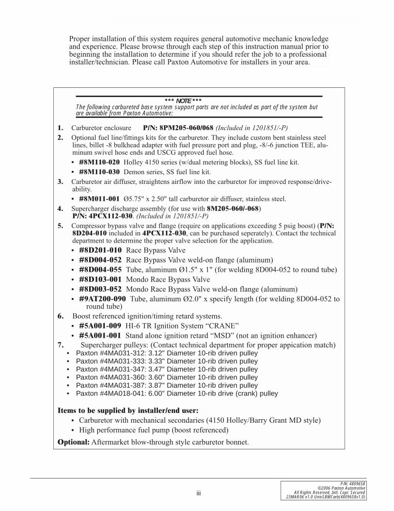
1. Carburetor enclosure P/N: 8PM205-060/068 (Included in 1201851/-P)2. Optional fuel line/fittings kits for the carburetor. They include custom bent stainless steel
lines, billet -8 bulkhead adapter with fuel pressure port and plug, -8/-6 junction TEE, alu-minum swivel hose ends and USCG approved fuel hose.• #8M110-020 Holley 4150 series (w/dual metering blocks), SS fuel line kit.• #8M110-030 Demon series, SS fuel line kit.
3. Carburetor air diffuser, straightens airflow into the carburetor for improved response/drive-ability.• #8M011-001 Ø5.75" x 2.50" tall carburetor air diffuser, stainless steel.
4. Supercharger discharge assembly (for use with 8M205-060/-068) P/N: 4PCX112-030. (Included in 1201851/-P)
5. Compressor bypass valve and flange (require on applications exceeding 5 psig boost) (P/N:8D204-010 included in 4PCX112-030, can be purchased seperately). Contact the technicaldepartment to determine the proper valve selection for the application.• #8D201-010 Race Bypass Valve• #8D004-052 Race Bypass Valve weld-on flange (aluminum)• #8D004-055 Tube, aluminum Ø1.5" x 1" (for welding 8D004-052 to round tube)• #8D103-001 Mondo Race Bypass Valve• #8D003-052 Mondo Race Bypass Valve weld-on flange (aluminum)• #9AT200-090 Tube, aluminum Ø2.0" x specify length (for welding 8D004-052 to
round tube)6. Boost referenced ignition/timing retard systems.
• #5A001-009 HI-6 TR Ignition System “CRANE”• #5A001-001 Stand alone ignition retard “MSD” (not an ignition enhancer)
7. Supercharger pulleys: (Contact technical department for proper appication match)• Paxton #4MA031-312: 3.12" Diameter 10-rib driven pulley• Paxton #4MA031-333: 3.33" Diameter 10-rib driven pulley• Paxton #4MA031-347: 3.47" Diameter 10-rib driven pulley• Paxton #4MA031-360: 3.60" Diameter 10-rib driven pulley• Paxton #4MA031-387: 3.87" Diameter 10-rib driven pulley• Paxton #4MA018-041: 6.00" Diameter 10-rib drive (crank) pulley
Items to be supplied by installer/end user:• Carburetor with mechanical secondaries (4150 Holley/Barry Grant MD style)• High performance fuel pump (boost referenced)
Optional: Aftermarket blow-through style carburetor bonnet.

iv
P/N: 4809658©2006 Paxton AutomotiveAll Rights Reserved, Intl. Copr. Secured23MAR06 v1.0 UnivSBMCarb(4809658v1.0)
This Page Left Intentionally Blank
v
P/N: 4809658©2006 Paxton Automotive
All Rights Reserved, Intl. Copr. Secured23MAR06 v1.0 UnivSBMCarb(4809658v1.0)
TABLE OF CONTENTS
FOREWORDFOREWORD . . . . . . . . . . . . . . . . . . . . . . . . . . . . . . . . . . . . . . . . . . . . . . . . . . . . . . . . . . . . . . . . . .ii
CARBURETED BASE SYSTEM SUPPORT PARTS . . . . . . . . . . . . . . . . . . . . . . . . . . . . . . . . . . .iii
TABLE OF CONTENTS . . . . . . . . . . . . . . . . . . . . . . . . . . . . . . . . . . . . . . . . . . . . . . . . . . . . . . . . . .v
TOOL & SUPPLY REQUIREMENTS . . . . . . . . . . . . . . . . . . . . . . . . . . . . . . . . . . . . . . . . . . . . . . .vi
PARTS LIST (Small Block Mopar 318/340/360 - 1201850-P) . . . . . . . . . . . . . . . . . . . . . . . . . . . . . .vii
PARTS LIST (Small Block Mopar 318/340/360 - 1201851-P) . . . . . . . . . . . . . . . . . . . . . . . . . . . . .viii
1. INTRODUCTION . . . . . . . . . . . . . . . . . . . . . . . . . . . . . . . . . . . . . . . . . . . . . . . . . . . . . . . . .1-1
2. PREPARATION/REMOVAL . . . . . . . . . . . . . . . . . . . . . . . . . . . . . . . . . . . . . . . . . . . . . . . . .2-1
3. OIL FEED INSTALLATION . . . . . . . . . . . . . . . . . . . . . . . . . . . . . . . . . . . . . . . . . . . . . . . . .3-1
4. OIL DRAIN INSTALLATION . . . . . . . . . . . . . . . . . . . . . . . . . . . . . . . . . . . . . . . . . . . . . . . .4-1
5. MOUNTING BRACKET/SUPERCHARGER INSTALLATION . . . . . . . . . . . . . . . . . . . . . .5-1
6. CRANK PULLEY AND SUPERCHARGER DRIVE PULLEY INSTALLATION . . . . . . . . .6-1
7. AIR DUCTING INSTALLATION . . . . . . . . . . . . . . . . . . . . . . . . . . . . . . . . . . . . . . . . . . . . .7-1
8. CARBURETOR MODIFICATIONS . . . . . . . . . . . . . . . . . . . . . . . . . . . . . . . . . . . . . . . . . . .8-1
9. DISCHARGE INSTALLATION (Option) . . . . . . . . . . . . . . . . . . . . . . . . . . . . . . . . . . . . . . .9-1
10. FINAL RE-ASSEMBLY AND CHECK . . . . . . . . . . . . . . . . . . . . . . . . . . . . . . . . . . . . . . . .10-1
vi
P/N: 4809658©2006 Paxton AutomotiveAll Rights Reserved, Intl. Copr. Secured23MAR06 v1.0 UnivSBMCarb(4809658v1.0)
Universal Small Block MoparCarbureted System
Installation Instructions
PLEASE READ CAREFULLY
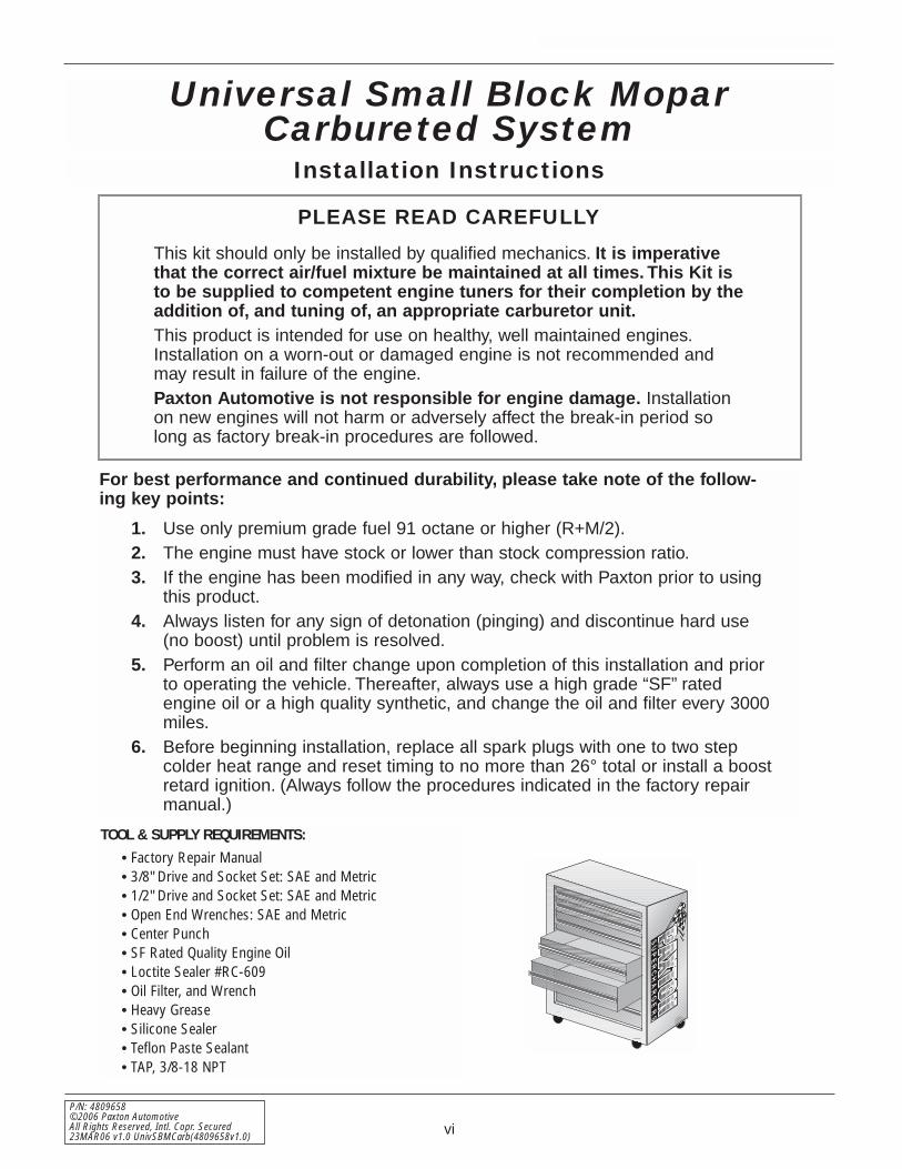
This kit should only be installed by qualified mechanics. It is imperativethat the correct air/fuel mixture be maintained at all times. This Kit isto be supplied to competent engine tuners for their completion by theaddition of, and tuning of, an appropriate carburetor unit.This product is intended for use on healthy, well maintained engines.Installation on a worn-out or damaged engine is not recommended andmay result in failure of the engine.Paxton Automotive is not responsible for engine damage. Installationon new engines will not harm or adversely affect the break-in period solong as factory break-in procedures are followed.
For best performance and continued durability, please take note of the follow-ing key points:
1. Use only premium grade fuel 91 octane or higher (R+M/2).2. The engine must have stock or lower than stock compression ratio.3. If the engine has been modified in any way, check with Paxton prior to using
this product.4. Always listen for any sign of detonation (pinging) and discontinue hard use
(no boost) until problem is resolved.5. Perform an oil and filter change upon completion of this installation and prior
to operating the vehicle. Thereafter, always use a high grade “SF” ratedengine oil or a high quality synthetic, and change the oil and filter every 3000miles.
6. Before beginning installation, replace all spark plugs with one to two stepcolder heat range and reset timing to no more than 26° total or install a boostretard ignition. (Always follow the procedures indicated in the factory repairmanual.)
TOOL & SUPPLY REQUIREMENTS:
• Factory Repair Manual• 3/8" Drive and Socket Set: SAE and Metric • 1/2" Drive and Socket Set: SAE and Metric• Open End Wrenches: SAE and Metric• Center Punch• SF Rated Quality Engine Oil• Loctite Sealer #RC-609• Oil Filter, and Wrench• Heavy Grease• Silicone Sealer• Teflon Paste Sealant• TAP, 3/8-18 NPT
S U P E R C H A R G E R S

vii
P/N: 4809658©2006 Paxton Automotive
All Rights Reserved, Intl. Copr. Secured23MAR06 v1.0 UnivSBMCarb(4809658v1.0)
PART NO. DESCRIPTION QTY. PART NO. DESCRIPTION QTY.
IMPORTANT: Before beginning installation, verify that all parts are included in the kit. Report any shortages or damagedparts immediately.
Small Block Mopar “Tuner” Kit318/340/360
Part No. 1201850/-P
PARTS LISTS U P E R C H A R G E R S
1016118 S/C ASY, NOVI 1200, CW CURV 14PCX110-044 BRKT ASY, S/C MNT DDG CRB 1
4PCX010-044 BRKT, S/C MNT DODGE CARB 14PCX010-034 BRKT, S/C MNT SUPPT 12A017-102-132 SPACER, 1"OD x .406" x 1.321" 22A017-102-175 SPACER, 1"OD x .406" x 1.755" 32A017-102-427 SPACER, 1"OD x .406" x 4.276" 14PCX017-175 SPACER, .625"OD x .406" x 1.755" 17A375-100 3/8-16 x 1"G5 HXHD PLT 77A375-324 3/8-16 x 3-1/4"HXHD GR5 PLD 17A375-451 3/8-16 x 4.50"HXHD GR5 ZINC 27A375-527 3/8-16 x 5.25"HXHD GR8 17K375-030 3/8"AN FLAT WASHER SS 157F375-017 3/8-16 NYLOCK NUT 2
4PCX118-011 10-RIB DRIVE ASY, SB DODGE CARB 12A017-093 SPACER, S/C PULLEY, .093" 12A040-011 PULLEY RETAINER S/C 17K375-040 3/8"AN960 FLAT WASHER PLATED 17U100-071 KEY, 3/16" SQUARE x 1-1/8"LONG 17B375-150 3/8-24 x 1-1/2" GR8 HX 17J012-092 12mm WASHER, FLAT 37G010-175 12mm x 1.75" NUT 17C012-065 M12 x 1.75" x 65mm HX 17C012-020 M12 x 1.75" x 20mm HXHD CL8.8 34FA016-171 DUST COVER (IDLER PULLEY) 14FA011-042 BELT TENS. PLATE, HEAVY DUTY 14PCX017-085 SPACER, S/C TNSR. IDLER PLY 14MA116-160 IDLER ASY, MARINE GEN2 12A041-607 BELT, K100607 GATES 10-RIB 14PCX017-245 SPACER, UNIVS. CRANK PULLEY, 2.45" 14MA018-051 7" CRANK PULLEY, UNIVERSAL 17K312-001 5/16"AN WASHER, PLATED 67A312-375 5/16-18 x 3-3/4"SHCS 6
1019345 ASY, S/C OIL SUPPLY 17U250-090-320 OIL FEED HOSE, 32" -4 x 90° 17P125-005 1/8"NPT STR, x -4 JIC FTG STL 17P125-004 1/8"NPT x 90° x -4 JIC FTG STL 17P125-034 1/8"NPT x 1/8"NPT STRT T 1
4FP130-036 OIL DRAIN ASY 17U030-036 1/2" OIL DRAIN HOSE 1.5'7R001-008 #8 STNLS HOSE CLAMP 27P375-017 3/8"NPT x 1/2" BEADED HOSE BARB 1
4PCX112-010 INLET ASY, S.B. DODGE CARB 18H040-030 AIR FILTER 3.5"FLG x 6"L 14FA012-011 INTAKE TUBE, 180° w/o BOSSES 17PS350-200 SLEEVE, BLACK 3.50"ID x 2.0"LG 17R002-056 #56 SAE TYPE “F” SS HOSE CLAMP 3
OPTIONAL EQUIPMENT4MA031-275 S/C PULLEY, 2.75" 14MA0310295 S/C PULLEY, 2.95" 14MA031-312 S/C DRIVE PULLEY 3.12" 14MA031-333 S/C DRIVE PULLEY 3.33" 14MA031-347 S/C DRIVE PULLEY 3.47" 14MA031-360 S/C DRIVE PULLEY 3.60" 14MA031-387 S/C DRIVE PULLEY 3.87" 15A001-008 HI-6 TR IGN. SYSTEM, CRANE 18M110-020 FUEL LINE ASY, HOLLEY 4150 18M110-030 FUEL LINE ASY, DEMON CARB. 1
(INCLUDED IN 1201851/-P)
4PCX112-030 DISC. ASY, SB. DDG W/CARB. ENCLOSURE 18M205-060 CARB. ENCL. ASY UNIV SAT. 1

viii
P/N: 4809658©2006 Paxton AutomotiveAll Rights Reserved, Intl. Copr. Secured23MAR06 v1.0 UnivSBMCarb(4809658v1.0)
PART NO. DESCRIPTION QTY. PART NO. DESCRIPTION QTY.
IMPORTANT: Before beginning installation, verify that all parts are included in the kit. Report any shortages or damagedparts immediately.
Small Block Mopar “Universal” Kit318/340/360
Part No. 1201851/-P
PARTS LISTS U P E R C H A R G E R S
1016118 S/C ASY, NOVI 1200, CW CURV 14PCX110-044 BRKT ASY, S/C MNT DDG CRB 1
4PCX010-044 BRKT, S/C MNT DODGE CARB 14PCX010-034 BRKT, S/C MNT SUPPT 12A017-102-132 SPACER, 1"OD x .406" x 1.321" 22A017-102-175 SPACER, 1"OD x .406" x 1.755" 32A017-102-427 SPACER, 1"OD x .406" x 4.276" 14PCX017-175 SPACER, .625"OD x .406" x 1.755" 17A375-100 3/8-16 x 1"G5 HXHD PLT 77A375-324 3/8-16 x 3-1/4"HXHD GR5 PLD 17A375-451 3/8-16 x 4.50"HXHD GR5 ZINC 27A375-527 3/8-16 x 5.25"HXHD GR8 17K375-030 3/8"AN FLAT WASHER SS 157F375-017 3/8-16 NYLOCK NUT 2
4PCX118-011 10-RIB DRIVE ASY, SB DODGE CARB 12A017-093 SPACER, S/C PULLEY, .093" 12A040-011 PULLEY RETAINER S/C 17K375-040 3/8"AN960 FLAT WASHER PLATED 17U100-071 KEY, 3/16" SQUARE x 1-1/8"LONG 17B375-150 3/8-24 x 1-1/2" GR8 HX 17J012-092 12mm WASHER, FLAT 37G010-175 12mm x 1.75" NUT 17C012-065 M12 x 1.75" x 65mm HX 17C012-020 M12 x 1.75" x 20mm HXHD CL8.8 34FA016-171 DUST COVER (IDLER PULLEY) 14FA011-042 BELT TENS. PLATE, HEAVY DUTY 14PCX017-085 SPACER, S/C TNSR. IDLER PLY 14MA116-160 IDLER ASY, MARINE GEN2 12A041-607 BELT, K100607 GATES 10-RIB 14PCX017-245 SPACER, UNIVS. CRANK PULLEY, 2.45" 14MA018-051 7" CRANK PULLEY, UNIVERSAL 17K312-001 5/16"AN WASHER, PLATED 67A312-375 5/16-18 x 3-3/4"SHCS 6
1019345 ASY, S/C OIL SUPPLY 17U250-090-320 OIL FEED HOSE, 32" -4 x 90° 17P125-005 1/8"NPT STR, x -4 JIC FTG STL 17P125-004 1/8"NPT x 90° x -4 JIC FTG STL 17P125-034 1/8"NPT x 1/8"NPT STRT T 1
4FP130-036 OIL DRAIN ASY 17U030-036 1/2" OIL DRAIN HOSE 1.5'7R001-008 #8 STNLS HOSE CLAMP 27P375-017 3/8"NPT x 1/2" BEADED HOSE BARB 1
4PCX112-010 INLET ASY, S.B. DODGE CARB 18H040-030 AIR FILTER 3.5"FLG x 6"L 14FA012-011 INTAKE TUBE, 180° w/o BOSSES 17PS350-200 SLEEVE, BLACK 3.50"ID x 2.0"LG 17R002-056 #56 SAE TYPE “F” SS HOSE CLAMP 3
4PCX112-030 DISC. ASY, SB. DDG W/CARB. ENCLOSURE 17PS350-200 SLEEVE, BLACK, 3.50"ID x 2.0" 14PFX012-031 DISCHARGE TUBE, SBF, '69 351 18D204-010 RACE BYPASS VALVE-BLACK 17R002-056 #56 SAE TYPE “F” SS HOSE CLAMP 37R002-044 #44 SAE TYPE “F” SS HOSE CLAMP 17U030-046 5/32" VACUUM LINE 37PS350-302 ELBOW, BLK-SIL 3.5" - 2.75" w/30 18M003-041 MACHINE, 3.5" FLANGE SATIN 1
8M205-060 CARB. ENCL. ASY UNIV SAT. G2 LID 1
OPTIONAL EQUIPMENT4MA031-275 S/C PULLEY, 2.75" GEN2 MERC 14MA0310295 S/C PULLEY, 2.95" GEN2 MERC 14MA031-312 S/C DRIVE PULLEY 3.12" GEN2 MERC 14MA031-333 S/C DRIVE PULLEY 3.33" GEN2 MERC 14MA031-347 S/C DRIVE PULLEY 3.47" GEN2 MERC 14MA031-360 S/C DRIVE PULLEY 3.60" GEN2 MERC 14MA031-387 S/C DRIVE PULLEY 3.87" GEN2 MERC 15A001-008 HI-6 TR IGN. SYSTEM, CRANE 18M110-020 FUEL LINE ASY, HOLLEY 4150 18M110-030 FUEL LINE ASY, DEMON CARB. 1
1-1
P/N: 4809658©2006 Paxton Automotive
All Rights Reserved, Intl. Copr. Secured23MAR06 v1.0 UnivSBMCarb(4809658v1.0)
Section 1INTRODUCTION
Congratulations! You have purchased thefinest street Supercharger available. Thecenterpiece of this kit is the highly effi-
cient and reliable Paxton Automotive Corp.NOVI-1200 supercharger. A mechanically driv-en (by belt) centrifugal blower (supercharger).This kit comes with all of the parts you’ll needfor a successful installation. The operationsrequired have been grouped in order ofsequence. Photos and drawings accompany thetext, allowing quick orientation and parts iden-tification.Installation requires a selection of tools whichare listed on page vi.We also suggest that you obtain a shop manualand become familiar with the details of yourcars systems. For best results follow the instructions closelyand in sequence. The average installation timefor this kit is 6 hours. Your actual installationtime will depend on skill level and workingconditions. The estimate does not include timefor initial vehicle inspection, cleaning, fine tun-ing or troubleshooting. Before even picking upa wrench, read this entire manual. We areavailable for technical assistance at (805) 487-3796, 8am-4:30pm pacific time.After reading the manual, verify that all majorassembly groups are present in the main kitbox. You should have ample space to layout thecomponents. As you remove a box or bag fromthe main kit, note the identification label andcompare it with the parts list. Please check thebox for small parts.Paxton makes every effort to insure that allparts are included in the box. However, if youdiscover any missing or mislabeled parts, pleasecontact Paxton by phone for service.
*** WARNING ***DO NOT attempt installation if any part(s) are miss-ing from this kit. Failure to contact Paxton prior tobeginning installation will result in a charge for anymissing parts.
Before starting the installation, we suggestyour engine compartment be clean. You canclean the engine and compartment with a pres-sure washer (such as those used at self serve carwashes) and a safe-for-aluminum
cleaner/degreaser. Cover the distributor with aplastic bag to prevent water from entering.
*** CAUTION ***We do not recommend proceeding with the kit instal-lation unless your vehicle is within normal operatingparameters.
You are undoubtedly enthusiastic about gettingstarted on your project, but take just a littlemore time to insure that your safety is not jeop-ardized. A moment’s lack of attention canresult in an accident, as can failure to observecertain simple safety precautions. The possibili-ty of an accident will always exist, and the fol-lowing points should not be considered a com-prehensive list of all dangers. Rather, they areintended to make you aware of the risk and toencourage a safety conscious approach to allwork you do on your vehicle.We look forward to hearing from you, particu-larly if you have any comments or suggestionsregarding this manual at:
(805) 487-3796 Paxton Automotive Corporation1300 Beacon PlaceOxnard, CA 93033E-mail [email protected].
*** NOTE ***Throughout these procedures the word “discard” is

1-2
P/N: 4809658©2006 Paxton AutomotiveAll Rights Reserved, Intl. Copr. Secured23MAR06 v1.0 UnivSBMCarb(4809658v1.0)
• Never rely solely on a jack when working under a vehicle. Alwaysuse an approved set of jackstands to support the vehicle and placethem under the recommended lift points.
• When jacking a vehicle, make sure it is on a level surface, preferablyconcrete or asphalt. The transmission should be in “PARK” or“FIRST”, the parking brake engaged and the wheels blocked.
• Never start the car without first verifying that the transmission is inneutral and the parking brake is set.
• Never remove the radiator cap while the engine is hot.• Always wear eye protection when using power tools such as drills,
saws, grinders, etc., or when working under a vehicle.• Never smoke, use an open flame, or have spark-producing items
around gasoline or flammable solvents. Always have a fire extin-guisher rated for chemical and electrical fires handy when working onmotor vehicles.
• Run engines only in well ventilated areas. Carbon monoxide, gaso-line, and solvent vapors are colorless and sometimes odorless. Thesecan asphyxiate or explode without warning.
• Always disconnect at least the negative (-) or ground terminal of thebattery when doing any electrical, fuel system, or underdash work.
Paxton Automotive makes every effort to insure that all parts are included in thebox, but mistakes do occur. If you discover that you are missing any part, orthat a part is damaged in transit, please call Paxton Automotive for service. DONOT attempt installation if any part(s) are missing from this kit. Failure to con-tact Paxton prior to beginning installation will result in a charge for any missingparts.
We look forward to hearing from you, particularly if you have any commentsor suggestions regarding this manual.

2-1
P/N: 4809658©2006 Paxton Automotive
All Rights Reserved, Intl. Copr. Secured23MAR06 v1.0 UnivSBMCarb(4809658v1.0)
Section 2PREPARATION/REMOVAL
2.1 PREPARATION/REMOVAL
A. Disconnect the negative lead of all batteries.
*** NOTE ***Refer to Fig. 2.1-a for the following steps.
B. Loosen all nuts and bolts that are used totension the alternator and power steeringpump V-belts.
C. Remove all of the belts from the accessories.D. Remove the stock crank pulley.E. Remove the alternator stay (adjustment bar)
and retain hardware to be reused in a laterstep.
*** NOTE ***If you have not changed spark plugs in the last15,000 miles do so prior to the installation of this kit.
F. Remove the remaining hardware securingthe alternator bracket to the cylinder head.Discard it and the bracket, as they will notbe reused.
*** NOTE ***If you are installing a universal supercharger kit,some of the following instructions may not apply ormay require custom fabrication.
Fig. 2.1-a
FACTORYALTERNATOR
BRACKET
FACTORYCRANK PULLEY
ALTERNATOR STAY

2-2
P/N: 4809658©2006 Paxton AutomotiveAll Rights Reserved, Intl. Copr. Secured23MAR06 v1.0 UnivSBMCarb(4809658v1.0)
This Page Left Intentionally Blank
3-1
P/N: 4809658©2006 Paxton Automotive
All Rights Reserved, Intl. Copr. Secured23MAR06 v1.0 UnivSBMCarb(4809658v1.0)
Section 3OIL FEED INSTALLATION
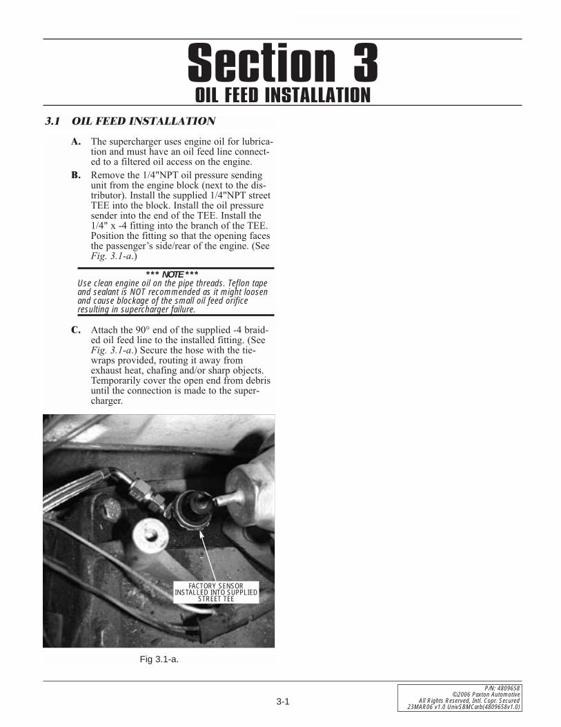
A. The supercharger uses engine oil for lubrica-tion and must have an oil feed line connect-ed to a filtered oil access on the engine.
B. Remove the 1/4"NPT oil pressure sendingunit from the engine block (next to the dis-tributor). Install the supplied 1/4"NPT streetTEE into the block. Install the oil pressuresender into the end of the TEE. Install the1/4" x -4 fitting into the branch of the TEE.Position the fitting so that the opening facesthe passenger’s side/rear of the engine. (SeeFig. 3.1-a.)
*** NOTE ***Use clean engine oil on the pipe threads. Teflon tapeand sealant is NOT recommended as it might loosenand cause blockage of the small oil feed orificeresulting in supercharger failure.
C. Attach the 90° end of the supplied -4 braid-ed oil feed line to the installed fitting. (SeeFig. 3.1-a.) Secure the hose with the tie-wraps provided, routing it away fromexhaust heat, chafing and/or sharp objects.Temporarily cover the open end from debrisuntil the connection is made to the super-charger.
3.1 OIL FEED INSTALLATION
Fig 3.1-a.
FACTORY SENSORINSTALLED INTO SUPPLIED
STREET TEE

3-2
P/N: 4809658©2006 Paxton AutomotiveAll Rights Reserved, Intl. Copr. Secured23MAR06 v1.0 UnivSBMCarb(4809658v1.0)
This Page Left Intentionally Blank
4-1
P/N: 4809658©2006 Paxton Automotive
All Rights Reserved, Intl. Copr. Secured23MAR06 v1.0 UnivSBMCarb(4809658v1.0)
Section 4OIL DRAIN INSTALLATION
4.1 OIL DRAIN INSTALLATION
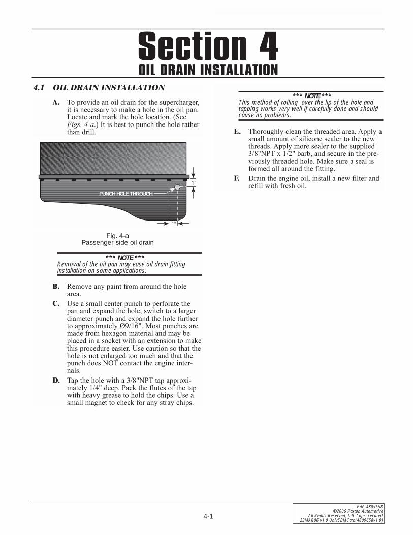
A. To provide an oil drain for the supercharger,it is necessary to make a hole in the oil pan.Locate and mark the hole location. (SeeFigs. 4-a.) It is best to punch the hole ratherthan drill.
*** NOTE ***This method of rolling over the lip of the hole andtapping works very well if carefully done and shouldcause no problems.
E. Thoroughly clean the threaded area. Apply asmall amount of silicone sealer to the newthreads. Apply more sealer to the supplied3/8"NPT x 1/2" barb, and secure in the pre-viously threaded hole. Make sure a seal isformed all around the fitting.
F. Drain the engine oil, install a new filter andrefill with fresh oil.
1"
1"
PUNCH HOLE THROUGH
*** NOTE ***Removal of the oil pan may ease oil drain fittinginstallation on some applications.
B. Remove any paint from around the holearea.
C. Use a small center punch to perforate thepan and expand the hole, switch to a largerdiameter punch and expand the hole furtherto approximately Ø9/16". Most punches aremade from hexagon material and may beplaced in a socket with an extension to makethis procedure easier. Use caution so that thehole is not enlarged too much and that thepunch does NOT contact the engine inter-nals.
D. Tap the hole with a 3/8"NPT tap approxi-mately 1/4" deep. Pack the flutes of the tapwith heavy grease to hold the chips. Use asmall magnet to check for any stray chips.
Fig. 4-aPassenger side oil drain

4-2
P/N: 4809658©2006 Paxton AutomotiveAll Rights Reserved, Intl. Copr. Secured23MAR06 v1.0 UnivSBMCarb(4809658v1.0)
This Page Left Intentionally Blank
Section 5MOUNTING BRACKET/SUPERCHARGER INSTALLATION
5-1
P/N: 4809658©2006 Paxton Automotive
All Rights Reserved, Intl. Copr. Secured23MAR06 v1.0 UnivSBMCarb(4809658v1.0)
5.1 MOUNTING BRACKET/SUPER-CHARGER INSTALLATION
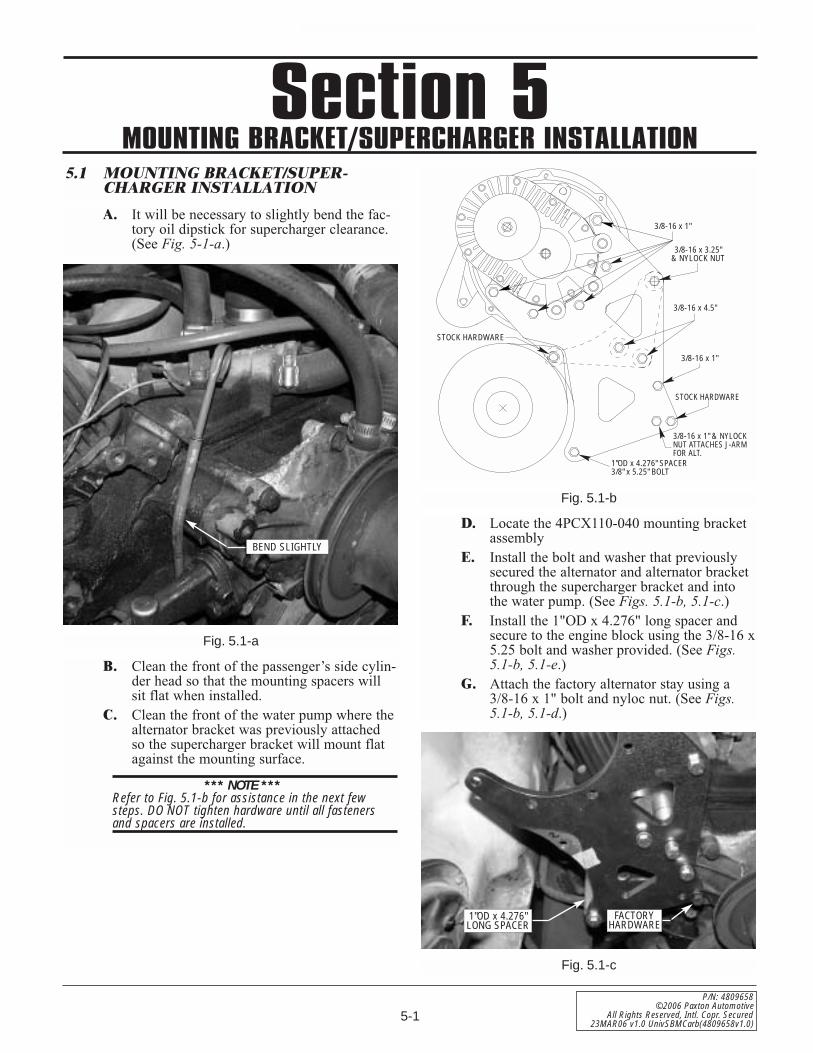
A. It will be necessary to slightly bend the fac-tory oil dipstick for supercharger clearance.(See Fig. 5-1-a.)
B. Clean the front of the passenger’s side cylin-der head so that the mounting spacers willsit flat when installed.
C. Clean the front of the water pump where thealternator bracket was previously attachedso the supercharger bracket will mount flatagainst the mounting surface.
*** NOTE ***Refer to Fig. 5.1-b for assistance in the next fewsteps. DO NOT tighten hardware until all fastenersand spacers are installed.
Fig. 5.1-a
1"OD x 4.276" SPACER3/8" x 5.25" BOLT
3/8-16 x 1" & NYLOCKNUT ATTACHES J-ARMFOR ALT.
STOCK HARDWARE
3/8-16 x 1"
3/8-16 x 4.5"
3/8-16 x 3.25"& NYLOCK NUT
3/8-16 x 1"
STOCK HARDWARE
Fig. 5.1-b
Fig. 5.1-c
D. Locate the 4PCX110-040 mounting bracketassembly
E. Install the bolt and washer that previouslysecured the alternator and alternator bracketthrough the supercharger bracket and intothe water pump. (See Figs. 5.1-b, 5.1-c.)
F. Install the 1"OD x 4.276" long spacer andsecure to the engine block using the 3/8-16 x5.25 bolt and washer provided. (See Figs.5.1-b, 5.1-e.)
G. Attach the factory alternator stay using a3/8-16 x 1" bolt and nyloc nut. (See Figs.5.1-b, 5.1-d.)
BEND SLIGHTLY
FACTORYHARDWARE
1"OD x 4.276"LONG SPACER
5-2
P/N: 4809658©2006 Paxton AutomotiveAll Rights Reserved, Intl. Copr. Secured23MAR06 v1.0 UnivSBMCarb(4809658v1.0)
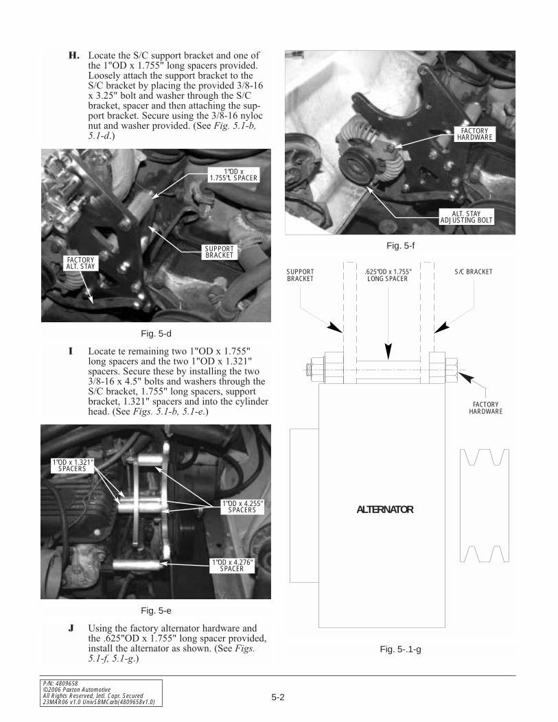
H. Locate the S/C support bracket and one ofthe 1"OD x 1.755" long spacers provided.Loosely attach the support bracket to theS/C bracket by placing the provided 3/8-16x 3.25" bolt and washer through the S/Cbracket, spacer and then attaching the sup-port bracket. Secure using the 3/8-16 nylocnut and washer provided. (See Fig. 5.1-b,5.1-d.)
I Locate te remaining two 1"OD x 1.755"long spacers and the two 1"OD x 1.321"spacers. Secure these by installing the two3/8-16 x 4.5" bolts and washers through theS/C bracket, 1.755" long spacers, supportbracket, 1.321" spacers and into the cylinderhead. (See Figs. 5.1-b, 5.1-e.)
J Using the factory alternator hardware andthe .625"OD x 1.755" long spacer provided,install the alternator as shown. (See Figs. 5.1-f, 5.1-g.)
Fig. 5-f
Fig. 5-.1-g
Fig. 5-d
Fig. 5-e
SUPPORTBRACKET
ALTERNATOR
.625"OD x 1.755"LONG SPACER
S/C BRACKET
FACTORYHARDWARE
1"OD x1.755"L SPACER
FACTORYHARDWARE
ALT. STAYADJUSTING BOLT
SUPPORTBRACKET
FACTORYALT. STAY
1"OD x 4.276"SPACER
1"OD x 4.255"SPACERS
1"OD x 1.321"SPACERS
5-3
P/N: 4809658©2006 Paxton Automotive
All Rights Reserved, Intl. Copr. Secured23MAR06 v1.0 UnivSBMCarb(4809658v1.0)
K. Attach the alternator stay to the alternatorusing the factory retainer.
L. Tighten all hardware installed to this point,making sure that all spacers and brackets areflat against their mounting surfaces. (SeeFig. 5.1-e.)
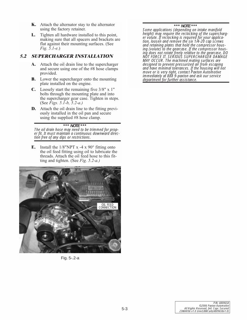
A. Attach the oil drain line to the superchargerand secure using one of the #8 hose clampsprovided.
B. Lower the supercharger onto the mountingplate installed on the engine.
C. Loosely start the remaining five 3/8" x 1"bolts through the mounting plate and intothe supercharger gear case. Tighten in steps.(See Figs. 5.1-b, 5.2-a.)
D. Attach the oil drain line to the fitting previ-ously installed in the oil pan and secureusing the supplied #8 hose clamp.
*** NOTE ***The oil drain hose may need to be trimmed for prop-er fit. It must maintain a continuous downward direc-tion free of any dips or restrictions.
E. Install the 1/8"NPT x -4 x 90° fitting ontothe oil feed fitting using oil to lubricate thethreads. Attach the oil feed hose to this fit-ting and tighten. (See Fig. 5.2-a.)
Fig. 5-.2-a
5.2 SUPERCHARGER INSTALLATION
*** NOTE ***Some applications (depending on intake manifoldheight) may require the reclocking of the supercharg-er volute. If reclocking is required for your applica-tion, loosen and remove the six 1/4-20 cap screwsand retaining plates that hold the compressor hous-ing (volute) to the gearcase. If the compressor hous-ing does not rotate freely relative to the gearcase, DONOT FORCE IT. SERIOUS SUPERCHARGER DAMAGEMAY OCCUR. The machined mating surfaces aredesigned to prevent pressurized air from escapingand have minimal tolerances. If the housing will notmove or is very tight, contact Paxton Automotiveimmediately at 888 9-paxton and ask our servicedepartment for further assistance.
OIL FEEDCONNECTION

5-4
P/N: 4809658©2006 Paxton AutomotiveAll Rights Reserved, Intl. Copr. Secured23MAR06 v1.0 UnivSBMCarb(4809658v1.0)
This Page Left Intentionally Blank
6-1
P/N: 4809658©2006 Paxton Automotive
All Rights Reserved, Intl. Copr. Secured23MAR06 v1.0 UnivSBMCarb(4809658v1.0)
Section 6CRANK PULLEY AND SUPERCHARGER DRIVE PULLEY INSTALLATION6.1 CRANK PULLEY AND SUPERCHARG-
ER DRIVE PULLEY INSTALLATION
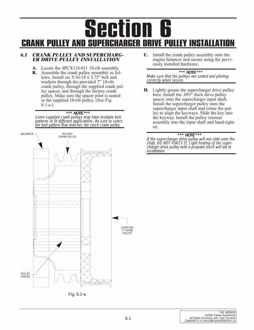
A. Locate the 4PCX118-011 10-rib assembly.B. Assemble the crank pulley assembly as fol-
lows. Install six 5/16-18 x 3.75" bolt andwashers through the provided 7" 10-ribcrank pulley, through the supplied crank pul-ley spacer, and through the factory crankpulley. Make sure the spacer pilot is seatedin the supplied 10-rib pulley. (See Fig. 6.1-a.)
*** NOTE ***Some supplied crank pulleys may have multiple boltpatterns to fit different applications. Be sure to selectthe bolt pattern that matches the stock crank pulley.
C. Install the crank pulley assembly onto theengine balancer and secure using the previ-ously installed hardware.
*** NOTE ***Make sure that the pulleys are seated and pilotingcorrectly when secure.
D. Lightly grease the supercharger drive pulleybore. Install the .093" thick drive pulleyspacer onto the supercharger input shaft.Install the supercharger pulley onto thesupercharger input shaft and rotate the pul-ley to align the keyways. Slide the key intothe keyway. Install the pulley retainerassembly into the input shaft and hand-tight-en.
*** NOTE ***If the supercharger drive pulley will not slide onto theshaft, DO NOT FORCE IT. Light heating of the super-charger drive pulley with a propane torch will aid ininstallation.
PULLEYSPACER
BALANCER FACTORYCRANK PULLEY
SUPPLIED7" 10-RIBPULLEY
Fig. 6.1-a
6-2
P/N: 4809658©2006 Paxton AutomotiveAll Rights Reserved, Intl. Copr. Secured23MAR06 v1.0 UnivSBMCarb(4809658v1.0)
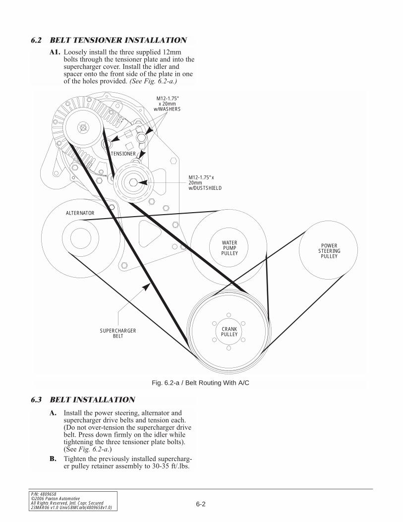
M12-1.75"x 20mm
w/WASHERS
M12-1.75" x20mmw/DUSTSHIELD
SUPERCHARGERBELT
ALTERNATOR
WATERPUMP
PULLEYPOWER
STEERINGPULLEY
CRANKPULLEY
TENSIONER
Fig. 6.2-a / Belt Routing With A/C
A1. Loosely install the three supplied 12mmbolts through the tensioner plate and into thesupercharger cover. Install the idler andspacer onto the front side of the plate in oneof the holes provided. (See Fig. 6.2-a.)
A. Install the power steering, alternator andsupercharger drive belts and tension each.(Do not over-tension the supercharger drivebelt. Press down firmly on the idler whiletightening the three tensioner plate bolts).(See Fig. 6.2-a.)
B. Tighten the previously installed supercharg-er pulley retainer assembly to 30-35 ft/.lbs.
6.2 BELT TENSIONER INSTALLATION
6.3 BELT INSTALLATION
7-1
P/N: 4809658©2006 Paxton Automotive
All Rights Reserved, Intl. Copr. Secured23MAR06 v1.0 UnivSBMCarb(4809658v1.0)
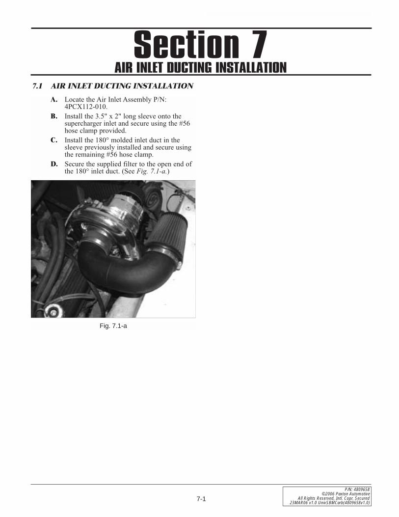
7.1 AIR INLET DUCTING INSTALLATION
Fig. 7.1-a
A. Locate the Air Inlet Assembly P/N:4PCX112-010.
B. Install the 3.5" x 2" long sleeve onto thesupercharger inlet and secure using the #56hose clamp provided.
C. Install the 180° molded inlet duct in thesleeve previously installed and secure usingthe remaining #56 hose clamp.
D. Secure the supplied filter to the open end ofthe 180° inlet duct. (See Fig. 7.1-a.)
Section 7AIR INLET DUCTING INSTALLATION

7-2
P/N: 4809658©2006 Paxton AutomotiveAll Rights Reserved, Intl. Copr. Secured23MAR06 v1.0 UnivSBMCarb(4809658v1.0)
This Page Left Intentionally Blank

8-1
P/N: 4809658©2006 Paxton Automotive
All Rights Reserved, Intl. Copr. Secured23MAR06 v1.0 UnivSBMCarb(4809658v1.0)
Section 8CARBURETOR MODIFICATIONS
8.1 CARBURETOR MODIFICATIONS
A. If you have purchased a 1201851/-P, a8M205-060/068 carburetor enclosure assem-bly was included. Please refer to the instruc-tion manual included with the carburetorenclosure at this time for carburetor installa-tion.
B. If you have purchased a 1201850/-P youwill need to provide a supercharger dis-charge to the carburetor. This may beaccomplished by using an enclosure orblow-through bonnet of some kind.

8-2
P/N: 4809658©2006 Paxton AutomotiveAll Rights Reserved, Intl. Copr. Secured23MAR06 v1.0 UnivSBMCarb(4809658v1.0)
This Page Left Intentionally Blank

9-1
P/N: 4809658©2006 Paxton Automotive
All Rights Reserved, Intl. Copr. Secured23MAR06 v1.0 UnivSBMCarb(4809658v1.0)
Section 9DISCHARGE INSTALLATION (OPTION)
9.1 DISCHARGE INSTALLATION (For Use With 8M205-060/068 CarbEnclosure)
A. Once the carburetor enclosure assemblyinstallation is complete per the instructionsincluded in that assembly, locate the4PCX112-030/038 discharge assembly.
*** NOTE ***Refer to Fig. 9-a for the following steps.
B. Using the supplied 1/4-20 hardware and gas-ket, attach the 3.5" aluminum flange to thecarburetor enclosure lid. (See Fig. 9-a.).
C. Secure the 3.5" x 2.0" sleeve to the flangeusing a supplied #56 hose clamp.
D. Locate the supplied Race By-Pass Valve.Secure the valve to the Ø3.5" tube/w weldedflange using the supplied 1/4-20 hardwareand gasket. (See Fig. 9-a.)
E. Install the by-pass valve assembly into thepreviously installed 3.5" sleeve and secureusing a #56 hose clamp provided. The by-pass valve discharge should face the passen-ger’s side of the vehicle. (See Fig. 9-a.)
F. Connect the 3.5" to 2.75" x 90° moldedelbow between the by-pass tube and super-charger discharge and secure using theremaining #56 and #44 hose clamps sup-plied. (See Fig. 9-a.)
G. Connect the supplied vacuum line to thevacuum port on the by-pass valve. Locate anengine vacuum source and secure the openend of the previously installed vacuum line.
*** NOTE ***The vacuum source used should be non-portedintake manifold vacuum.
Fig. 9-a
3.5" FLANGEBY-PASS VALVE
VACUUMPORT
3.5" TO 2.75"x 90° ELBOW
*** NOTE ***Some applications (depending on intake manifoldheight) may require the reclocking of the supercharg-er volute. If reclocking is required for your applica-tion, loosen and remove the six 1/4-20 cap screwsand retaining plates that hold the compressor hous-ing (volute) to the gearcase. If the compressor hous-ing does not rotate freely relative to the gearcase, DONOT FORCE IT. SERIOUS SUPERCHARGER DAMAGEMAY OCCUR. The machined mating surfaces aredesigned to prevent pressurized air from escapingand have minimal tolerances. If the housing will notmove or is very tight, contact Paxton Automotiveimmediately at 888 9-paxton and ask our servicedepartment for further assistance.

9-2
P/N: 4809658©2006 Paxton AutomotiveAll Rights Reserved, Intl. Copr. Secured23MAR06 v1.0 UnivSBMCarb(4809658v1.0)
This Page Left Intentionally Blank
10-1
P/N: 4809658©2006 Paxton Automotive
All Rights Reserved, Intl. Copr. Secured23MAR06 v1.0 UnivSBMCarb(4809658v1.0)
Section 10FINAL RE-ASSEMBLY AND CHECK
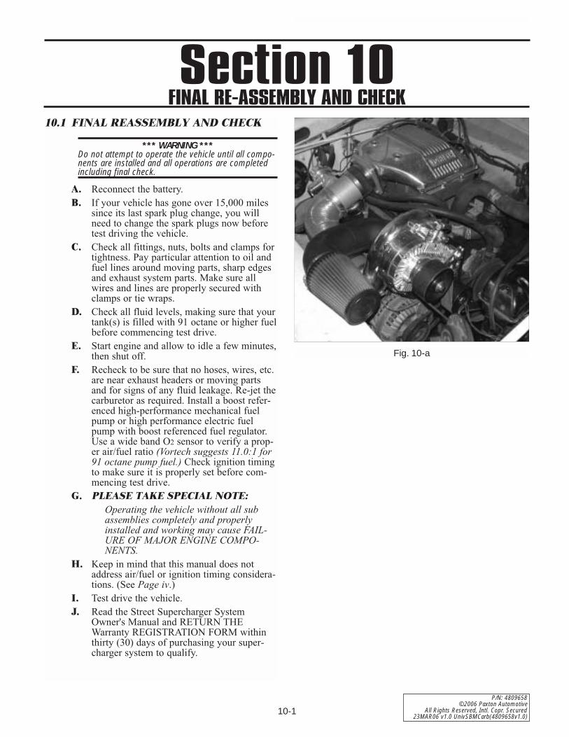
10.1 FINAL REASSEMBLY AND CHECK
*** WARNING ***Do not attempt to operate the vehicle until all compo-nents are installed and all operations are completedincluding final check.
A. Reconnect the battery.B. If your vehicle has gone over 15,000 miles
since its last spark plug change, you willneed to change the spark plugs now beforetest driving the vehicle.
C. Check all fittings, nuts, bolts and clamps fortightness. Pay particular attention to oil andfuel lines around moving parts, sharp edgesand exhaust system parts. Make sure allwires and lines are properly secured withclamps or tie wraps.
D. Check all fluid levels, making sure that yourtank(s) is filled with 91 octane or higher fuelbefore commencing test drive.
E. Start engine and allow to idle a few minutes,then shut off.
F. Recheck to be sure that no hoses, wires, etc.are near exhaust headers or moving partsand for signs of any fluid leakage. Re-jet thecarburetor as required. Install a boost refer-enced high-performance mechanical fuelpump or high performance electric fuelpump with boost referenced fuel regulator.Use a wide band O2 sensor to verify a prop-er air/fuel ratio (Vortech suggests 11.0:1 for91 octane pump fuel.) Check ignition timingto make sure it is properly set before com-mencing test drive.
G. PLEASE TAKE SPECIAL NOTE:Operating the vehicle without all subassemblies completely and properlyinstalled and working may cause FAIL-URE OF MAJOR ENGINE COMPO-NENTS.
H. Keep in mind that this manual does notaddress air/fuel or ignition timing considera-tions. (See Page iv.)
I. Test drive the vehicle. J. Read the Street Supercharger System
Owner's Manual and RETURN THEWarranty REGISTRATION FORM withinthirty (30) days of purchasing your super-charger system to qualify.
Fig. 10-a

DP/N: 4809658 v1.0 03/23/06
1300 Beacon Place • Oxnard, CA 93033-9901 • (805) 604-1336FAX (805) 604-1337 • paxtonautomotive.com • M-F 8:00 AM - 4:30 PM PST
S U P E R C H A R G E R S
Related Documents


