ISSUE 4 SEPTEMBER 2008 47 - 262 Morgana Systems Limited United Kingdom Telephone: ( 01908 ) 608888 Facsimile: ( 01908 ) 692399 ElectroCreaser 36 Website: W W W .Morgana.co.uk

Welcome message from author
This document is posted to help you gain knowledge. Please leave a comment to let me know what you think about it! Share it to your friends and learn new things together.
Transcript
ISSUE 4 SEPTEMBER 2008
47 - 262
Morgana Systems Limited United Kingdom
Telephone: ( 01908 ) 608888 Facsimile: ( 01908 ) 692399
ElectroCreaser 36
Website: W W W .Morgana.co.uk

Page 2 PAPER
SAFETY Do’s & Don’ts Page 3
LABELED DRAWING Page 4
OPERATING INSTRUCTIONS Page 6
ILLUSTRATED PARTS LIST Pages 7 to 11
WIRING DIAGRAM Page 12
ROUTINE MAINTENANCE Page 13
RECOMMENDED SPARES LIST Page 14
Specification
Overall Dimensions:- Length 700mmWidth 480mmHeight 218mmWeight 25Kgs
Maximum Crease:- Length 435mm(To Backstop) Width 365mm
Minimum Crease:- Length 35mm(To Backstop)
Power Requirement:- 1 phase 200 / 253v 50 / 60Hz
1 phase 100 / 125v 60Hz
INDEX

Page 3CREASER
ElectroCreaser 36 Safety Do’s & Don’ts
Safety Do’s & Don’ts
Do - operate with the designated AC current only. Use an exclusive outlet, as
overloading may cause fire or an electric shock.
Do - install the power cord out of the way to avoid a tripping hazard.
Do - beware of finger traps when replacing roller cassette and fold plates.
Do not - install the machine in an unstable place such that it tilts or shakes.Do not - unplug the plug or unplug the power cord from the outlet with a wet hand,
this can cause an electric shock.
Do not - unscrew and remove any covers from the machine, as it can cause an
electric shock or injury.
Do - read this operator manual fully before operating the machine.
Do not - place receptacles containing liquids on any surface.
Do not - adjust any part of the machine whilst rollers are running
Do not - operate the machine with loose or trailing clothing or loose hair.

Page 4 PAPER
1.S
ide
Lay
2.S
peed
Sto
ps
3.F
oo
tS
wit
ch
5.M
ain
sS
wit
ch
&F
use
6.C
op
yTab
le
7.W
idth
Ad
justm
en
tK
no
bs
1
4.V
olt
ag
eS
ele
cto
rS
wit
ch
LABELED DRAWING
22
3
45
6
77

Page 5CREASER
ElectroCreaser 36
BLANK
PAGE
Page 6 PAPER
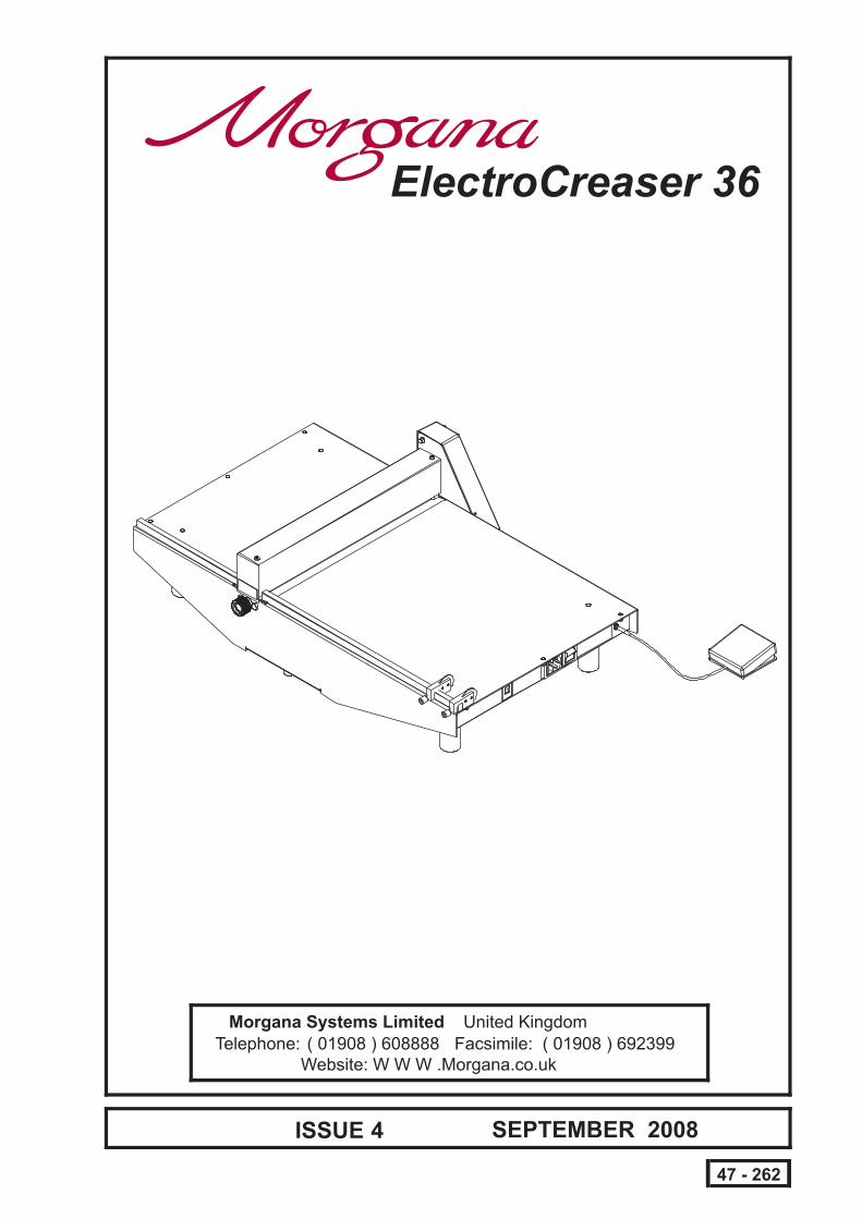
REFER TO LABELED DRAWING ON PAGE 3.
1. Check that the voltage selector switch (4) is set to the required inputvoltage,120V or 240V.
For 120V operation the fuse in the mains switch (5) must be a 4A anti-surge fuse, for 240V operation the fuse must be a 2A anti-surge fuse.
2. Switch on the power, mains switch (5).
3. Set the crease length as follows:-
(i) Line the face of the Speed Stop (2) up with the scale on the copy table(6) as shown below. (i.e. for a crease length of 100mm, line the face ofthe Speed Stop up with the 100mm mark on the copy table).
IMPORTANT.
OPERATING INSTRUCTIONS
4. Slide the sheet under the speed stops and against the side lays in thedirection of the creasing head. As the end speed stop drops down behindthe sheet edge, slide the sheet back to contact the stop. Press the footswitch to crease the sheet. Repeat this operation for as many stops thatare in use. Slide the sheet out of the machine.
5. The machine is set on the narrow crease at the factory. To change to thewider crease proceed as follows:-
(i) Undo the inner adjustment knob (7).
(ii) Turn the outer adjustment knob (7) until the spring loaded balllocates the wider crease position.
(iii) Lightly tighten the inner adjustment knob, place a sheet under thehead and operate the machine. This will centre the tools.
(iv) Tighten the inner adjustment knob securely.
Line this face of the Speed Stopup with the scale

Page 7CREASER
ElectroCreaser 36 ILLUSTRATED PARTS LIST
ITEM NO. PART No. QTY. Description
1 47-300-01 1 CREASER MECHANISM - Electrocreaser 36.
2 47-301-01 2 Speed Stop Assy.
3 47-069-04 1 LAY STRIP - Short - ElectroCreaser.
4 47-069-05 1 LAY STRIP - Long - ElectroCreaser.
5 1
6 1
7 1
8 1
9 1
10 1
11
47-219-01
1
END COVER PLATE.
12
47-220-01
1
FOLDED COVER PLATE.
13
47-221-01
1
SIDE COVER - Plastic.
14
47-222-01 MOTOR CAM - ElectroCreaser
15
47-224-01 Control Board Assy.
16
47-237-01 Label - Crease Width
17
47-266-01
1
Toroidal Transformer Assembly
18
47-267-01
1
Jack Socket Lead Assembly
19 1
20 1
21
47-255-01 4 LEG -ElectroCreaser.
22
47-257-01 1 Base - Electrocreaser MK2
23
47-258-01 1 Fuse Rating Label
24
601-109 4 FOOT - M4 - Black
25
601-150 3 NYLON PILLAR - M4 Male/Male
26
27
606-040 1 KNURLED KNOB - Female.
28
606-041 1 KNURLED KNOB - Male.
29
610-029 1 Doga - Motor & Gearbox
30
652-034 1 Microswitch
31
652-035 1 Foot Switch
32
651-094 1 FUSED POWER INLET.
33
652-036 1 Switch - Voltage Selector - 120/240V
34
656-003 4 PCB Mounting Pillar
35
660-001 1 Warning Label - Isolate
37
672-009 1 Bridge Rectifier
38
681-013 1 Fuse - 2A - 20 x 5mm - Anti-surge
39
681-015 1 Fuse - 4A - 20 x 5mm - Anti-surge
41
401-02-025-012 2 Screw - Pan Pozi Taptite - M2.5 x 12 Lg.
42
401-02-040-006 8 Screw - Pan Pozi Taptite - M4 x 6 Lg.
43
401-02-040-008 4 Screw - Pan Pozi Taptite - M4 x 8 Lg.
44
45
403-01-040-008 5 Screw - Socket Cap Head - M4 x 8 Lg.
46
47
48
49
409-01-060-030 3 Screw - Socket Set - Flat Point - M6 x 30 Lg.
50
415-01-060-012 4 Screw - Hexagon Head - M6 x 12 Lg.
51
52
461-01-025 1 Nut - Full - M2.5
53
461-01-040 3 Nut - Full - M4
54
461-01-060 6 Nut - Full - M6
55
463-01-040 10 Domed Nut - M4
56
481-040 16 Washer - Plain - M4
57
481-060 3 Washer - Plain - M6
58
604-080 2 Compression Spring
47-238-01 Label - Single Sheet Operation
47-253-01 Base Cover - Electrocreaser 36
47-254-01 Base - Hinged
47-265-03 Crank Block - Motor
47-265-04 Crank Block - Cam - Ø10l
604-085 1 Gas Strut
403-01-040-006 1 Screw - Socket Cap Head - M4 x 6 Lg.
403-01-040-010 1 Screw - Socket Cap Head - M4 x 10 Lg.
401-02-040-020 1 Screw - Pan Pozi Taptite - M4 x 20 Lg.
481-025 1 Washer - Plain - M2.5

Page 8 PAPER
ILLUSTRATED PARTS LIST
SE
EP
AG
E7
FO
RP
AR
TN
UM
BE
RS
LIS
T
22
24
6
50
22
50
52
22
442
342
46
46
38
52
52
15
25
11
7
3off
2off
in2
Posns.
2off
2off
in2
Posns.
3off
2off
52
Page 9CREASER
SE
EP
AG
E7
FO
RP
AR
TN
UM
BE
RS
LIS
T
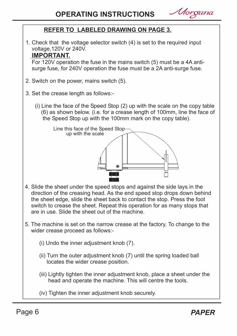
ElectroCreaser 36 ILLUSTRATED PARTS LIST
in4
Posns.
in2
Posns.
in4
Posns.
in4
Posns.
14
29
21
39
38
445 46
46
38
28
8
23
18
43
41
37
37
17
51
47
ILLUSTRATED PARTS LIST
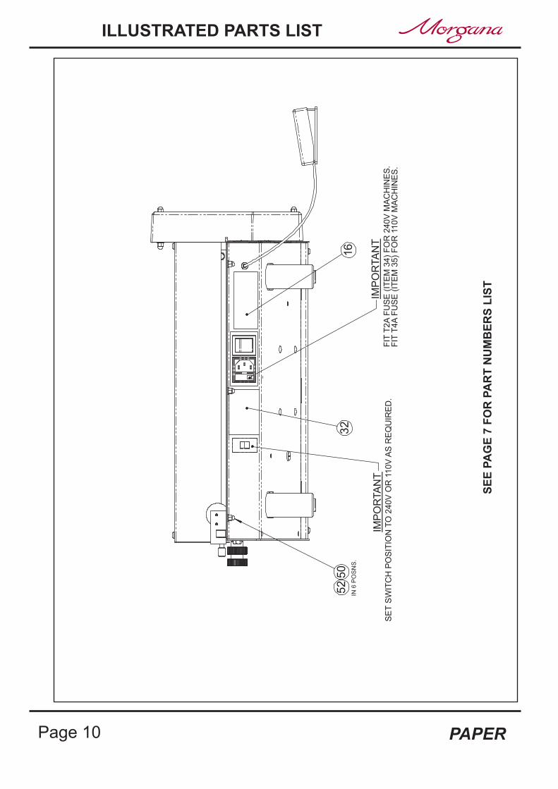
Page 10 PAPER
SE
EP
AG
E7
FO
RP
AR
TN
UM
BE
RS
LIS
T
SE
TS
WIT
CH
PO
SIT
ION
TO
240V
OR
110V
AS
RE
QU
IRE
D.
FIT
T2A
FU
SE
(IT
EM
34)
FO
R240V
MA
CH
INE
S.
FIT
T4A
FU
SE
(IT
EM
35)
FO
R11
0V
MA
CH
INE
S.
IN6
PO
SN
S.
50
52
32
16
IMP
OR
TA
NT
IMP
OR
TA
NT

Page 11CREASER
SE
EP
AG
E7
FO
RP
AR
TN
UM
BE
RS
LIS
T
XX
2o
ff
10
SE
CT
ION
X-X
12
13
33920
27
30
48
52
31
19
126
48
MO
TO
RF
IXIN
GS
(in
3P
osns.)
49 49
45
53
in4
Posns.
54
in2
Posns.
ElectroCreaser 36 ILLUSTRATED PARTS LIST

WIRING DIAGRAM
Page 12 PAPER
M RED
BLK
BLK
RED
MIC
RO
SW
ITC
HM
OT
OR
47
-26
9-0
1
RE
D
BL
K
PIN
K
BL
K
RE
D
47-2
24-0
1
RE
D
BLK
BL
K
RE
D
CO
NT
RO
LB
OA
RD
PC
BA
SS
EM
BLY
RE
D
ORANGE
+ACR
ED
BL
K
BLK
YEL
1B
2B
12
1A
2A
VO
LTA
GE
SE
LE
CT
OR
SW
ITC
H
GR
Y
VIO
BL
UB
RN
BL
KB
LK
47
-24
8-0
1
47
-24
6-0
1
47
-24
7-0
1
N L
E
2A 1A
5B 4B
MA
INS
INLE
TS
OC
KE
T(S
WIT
CH
ED
)
BL
U
BRN
BRN
BLU
BR
N
GRN/YEL
BLU
BLU
47
-24
3-0
14
7-2
44
-01
47-2
67-0
1
JA
CK
SO
CK
ET
TO
RO
IDA
LT
RA
NS
FO
RM
ER
AS
SE
MB
LY
47
-26
6-0
1
BR
IDG
ER
EC
TIF
IER
47
-25
9-0
1
EA
RT
HS
TU
D
47
-26
0-0
1
GR
N/Y
EL
ELE
CT
RO
NIC
SP
LA
TE
AS
SY.
47
-30
3-0
1

ROUTINE MAINTENANCE
It is recommended that the following lubrication is carried out atmonthly intervals
1. Remove the creasing head top cover.
2. Trickle oil into the slots, at both ends of the shaft, as shown in FIG.1 &FIG.2.
3. Liberally coat the top of the nuts and the areas of the shaft that contactthe head of the nuts with PTFE grease, as shown in FIG.3.
Oil Oil
FIG.1 FIG.2
FIG.3
PTFE Grease
Page 13CREASER
ElectroCreaser 36

RECOMMENDED SPARES LIST
NOTE....
The items listed above represents parts which are subject to wear, loss, oraccidental damage, and is included for your guidance only.Item numbers refer to the illustrations and tables in this manual.Replacement of parts fitted to your machine require specialist knowledge andshould therefore be entrusted to your dealer.
Page 14 PAPER
ITEM NO. PART No. QTY. Description
1 47-300-01 1 CREASER MECHANISM - Electrocreaser 36.
2 47-301-01 2 Speed Stop Assy.
28 652-034 1 Microswitch
19 47-266-01 1 Toroidal Transformer Assembly
21 601-109 4 FOOT - M4 - Black
24 606-040 1 KNURLED KNOB - Female.
25 606-041 1 KNURLED KNOB - Male.
26 610-029 1 Doga Motor & Gearbox
27 651-094 1 FUSED POWER INLET.
20 47-267-01 1 Jack Socket Lead Assembly
29 652-035 1 Foot Switch
33 672-009 1 Bridge Rectifier
681-013 1 Fuse - 2A - 20 x 5mm - Anti-surge Ceramic (For 240V Operation)
9 47-224-01 1 Control Board PCB Assembly
681-015 1 Fuse - 4A - 20 x 5mm - Anti-surge Ceramic (For 110V Operation)
34
35
604-080 2 Compression Spring54
23 604-085 1 GAS STRUT
Related Documents