1. FEATURES . . . . . . . . . . . . . . . . . . . . . . . . . . . . . . . . . . . . . . . . . . . . . 2 2. COMPATIBILITY . . . . . . . . . . . . . . . . . . . . . . . . . . . . . . . . . . . . . . . . 2 2.1. HEAT STAGES . . . . . . . . . . . . . . . . . . . . . . . . . . . . . . . . . . . . . . . . . . . . 2 2.2. COOLING/COMPRESSOR STAGES . . . . . . . . . . . . . . . . . . . . . . . . . . 2 2.3. ELECTRICAL RATINGS . . . . . . . . . . . . . . . . . . . . . . . . . . . . . . . . . . . . 2 3. INSTALLATION . . . . . . . . . . . . . . . . . . . . . . . . . . . . . . . . . . . . . . . . . 2 3.1. TOOLS REQUIRED . . . . . . . . . . . . . . . . . . . . . . . . . . . . . . . . . . . . . . . . 2 3.2. LOCATION . . . . . . . . . . . . . . . . . . . . . . . . . . . . . . . . . . . . . . . . . . . . . . . 3 3.3. REMOVAL OF OLD UNIT. . . . . . . . . . . . . . . . . . . . . . . . . . . . . . . . . . . 3 3.4. MOUNTING . . . . . . . . . . . . . . . . . . . . . . . . . . . . . . . . . . . . . . . . . . . . . . 3 3.5. WIRING . . . . . . . . . . . . . . . . . . . . . . . . . . . . . . . . . . . . . . . . . . . . . . . . . 3 3.5.1 TERMINAL DEFINITIONS . . . . . . . . . . . . . . . . . . . . . . . . . . . . . . . . . . . . 3 3.5.2 FREEZE PROTECTION. . . . . . . . . . . . . . . . . . . . . . . . . . . . . . . . . . . . . . . 4 3.5.3 SPECIAL WIRING NOTES. . . . . . . . . . . . . . . . . . . . . . . . . . . . . . . . . . . . 4 3.5.4 COMMON WIRING OPTIONS . . . . . . . . . . . . . . . . . . . . . . . . . . . . . . . . . 4 3.5.5 SINGLE STAGE HEATING SYSTEMS LABEL CROSS REFERENCE. . . . . 4 3.5.6 SINGLE STAGE COOLING SYSTEMS LABEL CROSS REFERENCE . . . . 4 3.5.7 SINGLE STAGE FURNACE HEATING AND SINGLE STAGE COOLING SYSTEM LABEL CROSS REFERENCE . . . . . . . . . . . . . . . . . . 4 3.5.8 TWO STAGE HEAT, SINGLE STAGE COOL HEAT PUMP SYSTEM LABEL CROSS REFERENCE . . . . . . . . . . . . . . . . . . . . . . . . . . . . . . . . . . 5 3.5.9 WIRING DIAGRAMS . . . . . . . . . . . . . . . . . . . . . . . . . . . . . . . . . . . . . . . . 5 3.6. INSTALL BATTERIES . . . . . . . . . . . . . . . . . . . . . . . . . . . . . . . . . . . . . . 9 3.7. INSTALLER SETUP. . . . . . . . . . . . . . . . . . . . . . . . . . . . . . . . . . . . . . . . 9 3.7.1 ACCESS AND NAVIGATE INSTALLER SETUP MENU . . . . . . . . . . . . . . . 9 3.7.2 INSTALLER SETUP MENU WITH FURNACE SYSTEM TYPE SELECTED: . . . . . . . . . . . . . . . . . . . . . . . . . . 10 3.7.3 INSTALLER SETUP MENU WITH HEAT PUMP SYSTEM TYPE SELECTED. . . . . . . . . . . . . . . . . . . . . . . . . . . . . . 10 3.7.4 COMPLETING YOUR INSTALLATION . . . . . . . . . . . . . . . . . . . . . . . . . . . 11 4. OPERATION . . . . . . . . . . . . . . . . . . . . . . . . . . . . . . . . . . . . . . . . . . . . 11 4.1. OPERATING BASICS . . . . . . . . . . . . . . . . . . . . . . . . . . . . . . . . . . . . . . 11 4.1.1 UP/DOWN ARROW CHANGE KEYS . . . . . . . . . . . . . . . . . . . . . . . . . . . . 11 4.1.2 SET DAY AND TIME . . . . . . . . . . . . . . . . . . . . . . . . . . . . . . . . . . . . . . . . 11 4.1.3 DEFAULT PROGRAM . . . . . . . . . . . . . . . . . . . . . . . . . . . . . . . . . . . . . . . 11 4.1.4 MODES . . . . . . . . . . . . . . . . . . . . . . . . . . . . . . . . . . . . . . . . . . . . . . . . . . 11 4.1.5 DISPLAY ILLUMINATION . . . . . . . . . . . . . . . . . . . . . . . . . . . . . . . . . . . . 12 4.2. USER SETUP MENU . . . . . . . . . . . . . . . . . . . . . . . . . . . . . . . . . . . . . . 12 4.2.1 ACCESS AND NAVIGATE USER SETUP MENU. . . . . . . . . . . . . . . . . . . . 12 4.2.2 KEYBOARD LOCK . . . . . . . . . . . . . . . . . . . . . . . . . . . . . . . . . . . . . . . . . . 12 4.2.3 BEEP . . . . . . . . . . . . . . . . . . . . . . . . . . . . . . . . . . . . . . . . . . . . . . . . . . . . 12 4.2.4 TEMPERATURE DISPLAY FORMAT (F/C DISPLAY) . . . . . . . . . . . . . . . . 13 4.2.5 CLOCK FORMAT . . . . . . . . . . . . . . . . . . . . . . . . . . . . . . . . . . . . . . . . . . . 13 4.2.6 CALIBRATION OFFSET . . . . . . . . . . . . . . . . . . . . . . . . . . . . . . . . . . . . . . 13 4.2.7 MAXIMUM HEAT SETTING. . . . . . . . . . . . . . . . . . . . . . . . . . . . . . . . . . . 13 4.2.8 MINIMUM COOL SETTING . . . . . . . . . . . . . . . . . . . . . . . . . . . . . . . . . . . 13 4.2.9 SMART RECOVERY . . . . . . . . . . . . . . . . . . . . . . . . . . . . . . . . . . . . . . . . 13 4.2.10 FILTER LIMIT . . . . . . . . . . . . . . . . . . . . . . . . . . . . . . . . . . . . . . . . . . . . . 13 4.2.11 USER SETUP MENU: . . . . . . . . . . . . . . . . . . . . . . . . . . . . . . . . . . . . . . . 13 4.3. ADVANCED FEATURES AND OPERATION . . . . . . . . . . . . . . . . . . . . 13 4.3.1 EMERGENCY HEAT. . . . . . . . . . . . . . . . . . . . . . . . . . . . . . . . . . . . . . . . . 13 4.3.2 FAN MODES . . . . . . . . . . . . . . . . . . . . . . . . . . . . . . . . . . . . . . . . . . . . . . 13 4.3.3 VACATION HOLD. . . . . . . . . . . . . . . . . . . . . . . . . . . . . . . . . . . . . . . . . . . 14 4.3.4 DAYLIGHT SAVINGS TIME ADJUSTMENT (DST) . . . . . . . . . . . . . . . . . 14 4.3.5 AIR FILTER . . . . . . . . . . . . . . . . . . . . . . . . . . . . . . . . . . . . . . . . . . . . . . . 14 4.3.6 ENERGY USAGE . . . . . . . . . . . . . . . . . . . . . . . . . . . . . . . . . . . . . . . . . . . 14 4.3.7 FUTURE OUTDOOR SENSOR . . . . . . . . . . . . . . . . . . . . . . . . . . . . . . . . . 14 4.3.8 FUTURE REMOTE INDOOR SENSORS. . . . . . . . . . . . . . . . . . . . . . . . . . 14 4.3.9 RESET . . . . . . . . . . . . . . . . . . . . . . . . . . . . . . . . . . . . . . . . . . . . . . . . . . . 14 4.4. PROGRAMMING. . . . . . . . . . . . . . . . . . . . . . . . . . . . . . . . . . . . . . . . . . 15 4.4.1 WEEKDAY TEMPERATURE PROGRAMMING. . . . . . . . . . . . . . . . . . . . . 15 4.4.2 WEEKDAY FAN PROGRAMMING . . . . . . . . . . . . . . . . . . . . . . . . . . . . . . 15 4.4.3 WEEKEND PROGRAMMING. . . . . . . . . . . . . . . . . . . . . . . . . . . . . . . . . . 15 4.4.4 COPY PROGRAMMING. . . . . . . . . . . . . . . . . . . . . . . . . . . . . . . . . . . . . . 16 5. BATTERIES/MAINTENANCE . . . . . . . . . . . . . . . . . . . . . . . . . . . . 16 5.1. BATTERY INSTALLATION . . . . . . . . . . . . . . . . . . . . . . . . . . . . . . . . . . 16 6. TECHNICAL DETAILS . . . . . . . . . . . . . . . . . . . . . . . . . . . . . . . . . . . 16 6.1. STAGING . . . . . . . . . . . . . . . . . . . . . . . . . . . . . . . . . . . . . . . . . . . . . . . . 16 7. TECHNICAL ASSISTANCE. . . . . . . . . . . . . . . . . . . . . . . . . . . . . . . 16 8. WARRANTY . . . . . . . . . . . . . . . . . . . . . . . . . . . . . . . . . . . . . . . . . . . . 16 LUXPRO EVERYTHING’STAT ® PSP722E INSTALLATION AND OPERATING INSTRUCTIONS Mt. Laurel, New Jersey 08054, USA l www.luxproproducts.com PSP722E WARNING: Use Energizer ® or DURACELL ® Alkaline Batteries Only. Energizer ® is a registered trademark of Eveready Battery Company, Inc. DURACELL ® is a registered trademark of The Gillette Company, Inc. 52026

Welcome message from author
This document is posted to help you gain knowledge. Please leave a comment to let me know what you think about it! Share it to your friends and learn new things together.
Transcript
1. FEATURES . . . . . . . . . . . . . . . . . . . . . . . . . . . . . . . . . . . . . . . . . . . . . 22. COMPATIBILITY . . . . . . . . . . . . . . . . . . . . . . . . . . . . . . . . . . . . . . . . 22.1. HEAT STAGES . . . . . . . . . . . . . . . . . . . . . . . . . . . . . . . . . . . . . . . . . . . . 22.2. COOLING/COMPRESSOR STAGES . . . . . . . . . . . . . . . . . . . . . . . . . . 22.3. ELECTRICAL RATINGS . . . . . . . . . . . . . . . . . . . . . . . . . . . . . . . . . . . . 23. INSTALLATION . . . . . . . . . . . . . . . . . . . . . . . . . . . . . . . . . . . . . . . . . 23.1. TOOLS REQUIRED . . . . . . . . . . . . . . . . . . . . . . . . . . . . . . . . . . . . . . . . 23.2. LOCATION . . . . . . . . . . . . . . . . . . . . . . . . . . . . . . . . . . . . . . . . . . . . . . . 33.3. REMOVAL OF OLD UNIT . . . . . . . . . . . . . . . . . . . . . . . . . . . . . . . . . . . 33.4. MOUNTING . . . . . . . . . . . . . . . . . . . . . . . . . . . . . . . . . . . . . . . . . . . . . . 33.5. WIRING . . . . . . . . . . . . . . . . . . . . . . . . . . . . . . . . . . . . . . . . . . . . . . . . . 33.5.1 TERMINAL DEFINITIONS . . . . . . . . . . . . . . . . . . . . . . . . . . . . . . . . . . . . 33.5.2 FREEZE PROTECTION. . . . . . . . . . . . . . . . . . . . . . . . . . . . . . . . . . . . . . . 43.5.3 SPECIAL WIRING NOTES . . . . . . . . . . . . . . . . . . . . . . . . . . . . . . . . . . . . 43.5.4 COMMON WIRING OPTIONS . . . . . . . . . . . . . . . . . . . . . . . . . . . . . . . . . 43.5.5 SINGLE STAGE HEATING SYSTEMS LABEL CROSS REFERENCE. . . . . 43.5.6 SINGLE STAGE COOLING SYSTEMS LABEL CROSS REFERENCE . . . . 43.5.7 SINGLE STAGE FURNACE HEATING AND SINGLE STAGE
COOLING SYSTEM LABEL CROSS REFERENCE . . . . . . . . . . . . . . . . . . 43.5.8 TWO STAGE HEAT, SINGLE STAGE COOL HEAT PUMP SYSTEM
LABEL CROSS REFERENCE . . . . . . . . . . . . . . . . . . . . . . . . . . . . . . . . . . 53.5.9 WIRING DIAGRAMS . . . . . . . . . . . . . . . . . . . . . . . . . . . . . . . . . . . . . . . . 53.6. INSTALL BATTERIES . . . . . . . . . . . . . . . . . . . . . . . . . . . . . . . . . . . . . . 93.7. INSTALLER SETUP. . . . . . . . . . . . . . . . . . . . . . . . . . . . . . . . . . . . . . . . 93.7.1 ACCESS AND NAVIGATE INSTALLER SETUP MENU . . . . . . . . . . . . . . . 93.7.2 INSTALLER SETUP MENU WITH
FURNACE SYSTEM TYPE SELECTED: . . . . . . . . . . . . . . . . . . . . . . . . . . 103.7.3 INSTALLER SETUP MENU WITH HEAT
PUMP SYSTEM TYPE SELECTED. . . . . . . . . . . . . . . . . . . . . . . . . . . . . . 103.7.4 COMPLETING YOUR INSTALLATION . . . . . . . . . . . . . . . . . . . . . . . . . . . 114. OPERATION . . . . . . . . . . . . . . . . . . . . . . . . . . . . . . . . . . . . . . . . . . . . 114.1. OPERATING BASICS . . . . . . . . . . . . . . . . . . . . . . . . . . . . . . . . . . . . . . 114.1.1 UP/DOWN ARROW CHANGE KEYS . . . . . . . . . . . . . . . . . . . . . . . . . . . . 114.1.2 SET DAY AND TIME . . . . . . . . . . . . . . . . . . . . . . . . . . . . . . . . . . . . . . . . 114.1.3 DEFAULT PROGRAM . . . . . . . . . . . . . . . . . . . . . . . . . . . . . . . . . . . . . . . 11
4.1.4 MODES . . . . . . . . . . . . . . . . . . . . . . . . . . . . . . . . . . . . . . . . . . . . . . . . . . 114.1.5 DISPLAY ILLUMINATION . . . . . . . . . . . . . . . . . . . . . . . . . . . . . . . . . . . . 124.2. USER SETUP MENU . . . . . . . . . . . . . . . . . . . . . . . . . . . . . . . . . . . . . . 124.2.1 ACCESS AND NAVIGATE USER SETUP MENU. . . . . . . . . . . . . . . . . . . . 124.2.2 KEYBOARD LOCK . . . . . . . . . . . . . . . . . . . . . . . . . . . . . . . . . . . . . . . . . . 124.2.3 BEEP . . . . . . . . . . . . . . . . . . . . . . . . . . . . . . . . . . . . . . . . . . . . . . . . . . . . 124.2.4 TEMPERATURE DISPLAY FORMAT (F/C DISPLAY) . . . . . . . . . . . . . . . . 134.2.5 CLOCK FORMAT . . . . . . . . . . . . . . . . . . . . . . . . . . . . . . . . . . . . . . . . . . . 134.2.6 CALIBRATION OFFSET . . . . . . . . . . . . . . . . . . . . . . . . . . . . . . . . . . . . . . 134.2.7 MAXIMUM HEAT SETTING. . . . . . . . . . . . . . . . . . . . . . . . . . . . . . . . . . . 134.2.8 MINIMUM COOL SETTING . . . . . . . . . . . . . . . . . . . . . . . . . . . . . . . . . . . 134.2.9 SMART RECOVERY . . . . . . . . . . . . . . . . . . . . . . . . . . . . . . . . . . . . . . . . 134.2.10 FILTER LIMIT . . . . . . . . . . . . . . . . . . . . . . . . . . . . . . . . . . . . . . . . . . . . . 134.2.11 USER SETUP MENU: . . . . . . . . . . . . . . . . . . . . . . . . . . . . . . . . . . . . . . . 134.3. ADVANCED FEATURES AND OPERATION . . . . . . . . . . . . . . . . . . . . 134.3.1 EMERGENCY HEAT. . . . . . . . . . . . . . . . . . . . . . . . . . . . . . . . . . . . . . . . . 134.3.2 FAN MODES . . . . . . . . . . . . . . . . . . . . . . . . . . . . . . . . . . . . . . . . . . . . . . 134.3.3 VACATION HOLD. . . . . . . . . . . . . . . . . . . . . . . . . . . . . . . . . . . . . . . . . . . 144.3.4 DAYLIGHT SAVINGS TIME ADJUSTMENT (DST) . . . . . . . . . . . . . . . . . 144.3.5 AIR FILTER . . . . . . . . . . . . . . . . . . . . . . . . . . . . . . . . . . . . . . . . . . . . . . . 144.3.6 ENERGY USAGE . . . . . . . . . . . . . . . . . . . . . . . . . . . . . . . . . . . . . . . . . . . 144.3.7 FUTURE OUTDOOR SENSOR . . . . . . . . . . . . . . . . . . . . . . . . . . . . . . . . . 144.3.8 FUTURE REMOTE INDOOR SENSORS. . . . . . . . . . . . . . . . . . . . . . . . . . 144.3.9 RESET . . . . . . . . . . . . . . . . . . . . . . . . . . . . . . . . . . . . . . . . . . . . . . . . . . . 144.4. PROGRAMMING. . . . . . . . . . . . . . . . . . . . . . . . . . . . . . . . . . . . . . . . . . 154.4.1 WEEKDAY TEMPERATURE PROGRAMMING. . . . . . . . . . . . . . . . . . . . . 154.4.2 WEEKDAY FAN PROGRAMMING . . . . . . . . . . . . . . . . . . . . . . . . . . . . . . 154.4.3 WEEKEND PROGRAMMING . . . . . . . . . . . . . . . . . . . . . . . . . . . . . . . . . . 154.4.4 COPY PROGRAMMING. . . . . . . . . . . . . . . . . . . . . . . . . . . . . . . . . . . . . . 165. BATTERIES/MAINTENANCE . . . . . . . . . . . . . . . . . . . . . . . . . . . . 165.1. BATTERY INSTALLATION . . . . . . . . . . . . . . . . . . . . . . . . . . . . . . . . . . 166. TECHNICAL DETAILS . . . . . . . . . . . . . . . . . . . . . . . . . . . . . . . . . . . 166.1. STAGING . . . . . . . . . . . . . . . . . . . . . . . . . . . . . . . . . . . . . . . . . . . . . . . . 167. TECHNICAL ASSISTANCE. . . . . . . . . . . . . . . . . . . . . . . . . . . . . . . 168. WARRANTY . . . . . . . . . . . . . . . . . . . . . . . . . . . . . . . . . . . . . . . . . . . . 16
LUXPRO EVERYTHING’STAT ® PSP722EINSTALLATION AND OPERATING INSTRUCTIONS
Mt. Laurel, New Jersey 08054, USA l www.luxproproducts.com
PSP722E
WARNING: Use Energizer® or DURACELL® Alkaline Batteries Only.Energizer® is a registered trademark of Eveready Battery Company, Inc.
DURACELL® is a registered trademark of The Gillette Company, Inc.
4.4.4 COPY PROGRAMMINGThe COPY button allows you to easily copy temperatureor fan programs from any day, to any other day, to allweekdays, to both weekend days, or all days. The Copyfunction copies only the temperature or fan programfrom a day, not both at the same time. To copy a day’stemperature or fan programs from one day to others:● In the appropriate programming mode press COPY.The display will show COPY FROM with current daybeing programmed flashing below.● Use the UP or DOWN arrow buttons to select the dayyou want to copy from. Selections are:
Any single day, SUN - SATAll weekdays MON to FRIBoth weekend days SAT and SUNAll days at once SUN – SAT
● Press NEXT.● Again use the UP or DOWN arrow buttons to select theday or days you want to copy.● Press NEXT to accept the displayed copy to days, andthe copy will be complete.5. BATTERIES/MAINTENANCEDepending on your installation, your unit may requirebatteries to control your HVAC system. If required,replace your thermostat’s batteries at least once a year orwhen the battery symbol appears in the display.5.1. BATTERY INSTALLATION1. Remove fresh batteries from their carton.2. Remove body of thermostat as described duringinstallation.3. Remove the used batteries if present and replace themwithin 90 seconds to avoid having to reset the day andtime.4. Install two new “AA” size Energizer or Duracell alkalinebatteries in the battery compartment. Observe the polari-ty marking shown in the compartment.
WARNING: Use Energizer® or DURACELL®
Alkaline Batteries Only.5. Place the thermostat body back on the wall.NOTE: Replace your thermostat’s batteries with new alkalinebatteries at least once a year or when the battery symbolappears in the display.The use of high quality alkaline batteries is absolutelyrequired for your thermostat to operate properly.
6. TECHNICAL DETAILS6.1. STAGING● Stage one of a heating system will be activated at thevalue of swing 1 below the temperature set point. Stageone of a cooling system will be activated at the value ofswing 1 above the temperature set point.● Stage one of a heating system will be deactivated atthe value of swing 1 above the temperature set point.
Stage one of a cooling system will be deactivated at thevalue of swing 1 below the temperature set point.● Stage two of a heating system will be activated at thevalue of (swing 1 + swing 2) below the temperature setpoint. The auxiliary heat indicator AUX HT will be visiblewhen a second stage of heat is activated. Stage two ofcooling will be activated at the value of (swing 1 + swing2) above the temperature set point.● Stage two of a heating or cooling system will be deac-tivated at the temperature set point.● Stage three of a heating system will be activated at thevalue of (swing 1 + 2*swing 2) below the temperatureset point. ● Stage three of a heating or cooling system will bedeactivated at the temperature set point.7. TECHNICAL ASSISTANCEIf you have any problems installing or using this thermo-stat, please carefully and thoroughly review the instruc-tion manual. If you require assistance, please contact ourTechnical Assistance Department at 856-234-8803 duringregular business hours between 8:00AM and 4:30PMEastern Standard Time, Monday through Friday. You canalso receive technical assistance online anytime day ornight at http://www.luxproproducts.com. Our web siteoffers you answers to the most common technical ques-tions, and also permits you to email your questions toour technical support staff at your convenience.8. WARRANTYLimited Warranty: If this unit fails because of defects inmaterials or workmanship within three years of date oforiginal purchase, LUX Products Corporation will, at itsoption, repair or replace it. This warranty does not coverdamage by accident, misuse, or failure to follow installa-tion instructions. Implied warranties are limited in dura-tion to three years from date of original purchase. Somestates do not allow limitations on how long an impliedwarranty lasts, so the above limitation may not apply toyou. Please return malfunctioning or defective units tothe participating retailer from which purchase was made,along with proof of purchase. Please refer to "TECHNICALASSISTANCE" before returning thermostat. Purchaserassumes all risks and liability for incidental and conse-quential damage resulting from installation and use ofthis unit. Some states do not allow the exclusion of inci-dental or consequential damages, so the above exclusionmay not apply to you. This warranty gives you specificlegal rights and you may also have other rights whichvary from state to state. Applicable in the U.S.A. only.
16
52026
Kurt
Rectangle
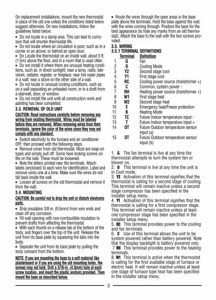
On replacement installations, mount the new thermostatin place of the old one unless the conditions listed belowsuggest otherwise. On new installations, follow theguidelines listed below.● Do not locate in a damp area. This can lead to corro-sion that will shorten thermostat life.● Do not locate where air circulation is poor, such as in acorner or an alcove; or behind an open door.● Do Locate the thermostat on an inside wall, about 5 ft.(1.5m) above the floor, and in a room that is used often.● Do not install it where there are unusual heating condi-tions, such as: in direct sunlight; near a lamp, radio, tele-vision, radiator, register, or fireplace; near hot water pipesin a wall; near a stove on the other side of a wall.● Do not locate in unusual cooling conditions, such as:on a wall separating an unheated room; or in a draft froma stairwell, door, or window.● Do not install the unit until all construction work andpainting has been completed.3.3. REMOVAL OF OLD UNITCAUTION: Read instructions carefully before removing anywiring from existing thermostat. Wires must be labeledbefore they are removed. When removing wires from theirterminals, ignore the color of the wires since they may notcomply with any standard.● Switch electricity to the furnace and air conditionerOFF; then proceed with the following steps.● Remove cover from old thermostat. Most are snap-ontypes and simply pull off. Some have locking screws onthe on the side. These must be loosened.● Note the letters printed near the terminals. Attachlabels (enclosed) to each wire for identification. Label andremove wires one at a time. Make sure the wires do notfall back inside the wall.● Loosen all screws on the old thermostat and remove itfrom the wall.3.4. MOUNTINGCAUTION: Be careful not to drop the unit or disturb electronicparts.● Strip insulation 3/8 in. (9.5mm) from wire ends andclean off any corrosion.● Fill wall opening with non-combustible insulation toprevent drafts from affecting the thermostat.● With each thumb on a release tab at the bottom of thebody, and fingers over the top of the unit. Release theunit from its base plate by squeezing the tabs into thebody.● Separate the unit from its base plate by pulling thebody outward from the bottom.NOTE: If you are mounting the base to a soft material likeplasterboard or if you are using the old mounting holes, thescrews may not hold. Drill a 3/16-in. (4.8mm) hole at eachscrew location, and insert the plastic anchors provided. Thenmount the base as described below.
● Route the wires through the open areas in the baseplate above the terminals. Hold the base against the wall,with the wires coming through. Position the base for thebest appearance (to hide any marks from an old thermo-stat). Attach the base to the wall with the two screws pro-vided.3.5. WIRING3.5.1 TERMINAL DEFINITIONS
Terminal Definition1 G Fan2 O Cooling Mode3 Y2 Second stage cool4 Y1 First stage cool5 RC Cooling power source (transformer +)6 C Common, system power -7 RH Heating power source (transformer +)8 W1 First stage heat9 W2 Second stage heat
10 E Emergency heat/Freeze protection11 B Heating Mode12 TC Future Indoor temperature input -13 T Future Indoor temperature input +14 OT Future Outdoor temperature sensor
input (a)15 OT Future Outdoor temperature sensor
input (b)
1. G The fan terminal is live at any time thethermostat attempts to turn the system fan orblower on.2. O This terminal is live at any time the unit isin Cool mode.3. Y2 Activation of this terminal signifies that thethermostat is calling for a second stage of cooling.This terminal will remain inactive unless a secondstage compressor has been specified in theinstaller setup menu.4. Y1 Activation of this terminal signifies that thethermostat is calling for a first compressor stage.This terminal will remain inactive unless at leastone compressor stage has been specified in theinstaller setup menu.5. RC This terminal provides power to the coolingand fan terminals.6. C Use of this terminal allows the unit to besystem powered rather than battery powered. Notethat the display backlight is battery powered only.7 RH This terminal provides power to the heatingterminals. 8. W1 This terminal is active when the thermostatis calling for the first available stage of furnace orelectric heat. It will remain inactive unless at leastone stage of furnace type heat has been specifiedin the installer setup menu.
3
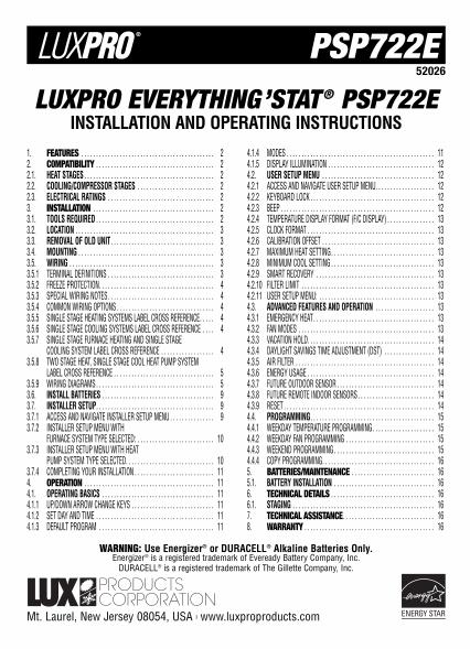
1. FEATURES● Universal Compatibility● Controls Up To 2 Stages Of Heat And 2 Stages Of
Cooling + Auxiliary and Emergency Heat● Large Hybrid Display● Auxiliary and Emergency Heat Indicators● Electro-luminescent Display Backlight ● Clean Cycle® (Patent No. 6,988,671)
Independently Programmable Fan● 7 Day Programming● Default ENERGY STAR Approved Program● 4 Periods Per Day● Temporary Override● Temperature Hold● Optional Smart Recovery● ENERGY STAR Compliant● Programmable Filter Timer With Change
Filter Indicator● Energy Usage Monitor● F/C Temperature Display● 12/24 Hour Clock● Easy Programming with LUX Speed Dial®● Advanced Copy Function For Fast Easy Programming● Nonvolatile Memory For All Programs And Settings● Daylight Saving Button● Multimode Keyboard Lockout With User
Programmable 3 Digit Code● Programmable High And Low Setting Limits● Silence-able Audible Button Response● Menu Driven Setup Done From The Front Panel● Temperature Offset (User Calibration)● Dual Power Capable (System/Battery)● Multi-Stage Adjustable Temperature Differential /
Cycle Rate● Programmable Length Minimum Run Time● Programmable Auto-Changeover Dead-Band● Programmable Fan Delays For Heat, Cool, In Both
On And Off2. COMPATIBILITYYour PSP722E is compatible with most 24 volt gas, oil,or electrical Heating and/or Cooling systems. It cannot beused with 120 volt heating systems. Ask your dealer forother LUXPRO thermostats to control those systems.2.1. HEAT STAGESThe PSP722E is capable of controlling systems with upto two stages of heat in furnace mode. In heat pumpmode, the thermostat can be configured to control up totwo stages of compressor driven heat plus auxiliary andemergency heat stages. NOTE: AUX HEAT ACTIVATION IS PROVIDED ATTERMINAL W12.2. COOLING/COMPRESSOR STAGESThe PSP722E is capable of controlling systems with upto two stages of cooling.2.3. ELECTRICAL RATINGS● 30V maximum (24VAC nominal)● 1.5A maximum per terminal● 2.0A terminal sum 3. INSTALLATION3.1. TOOLS REQUIRED● #1 Phillips screwdriver (small)● Drill with 3/16-in. (4.8mm) bit● Wire stripper/cutter3.2. LOCATION
2
COPY FAN
MODENEXT
NEXTRUNDST Setup
Auto On
SET WEEKENDPROGRAMS
SET WEEKDAYPROGRAMS
SET DAYAND TIME
AIRFILTER
ENERGYUSAGE
Auto Heat Off Cool
UP
LARGE HYBRID DISPLAYWITH ELECTRO-LUMINESCENTDISPLAY BACKLIGHT
EASYPROGRAMMING
WITHLUX SPEED DIAL®
DOWN
IAQ INDEPENDENTLYPROGRAMMABLEFAN
MENU DRIVENSETUP
PSP722E
On replacement installations, mount the new thermostatin place of the old one unless the conditions listed belowsuggest otherwise. On new installations, follow theguidelines listed below.● Do not locate in a damp area. This can lead to corro-sion that will shorten thermostat life.● Do not locate where air circulation is poor, such as in acorner or an alcove; or behind an open door.● Do Locate the thermostat on an inside wall, about 5 ft.(1.5m) above the floor, and in a room that is used often.● Do not install it where there are unusual heating condi-tions, such as: in direct sunlight; near a lamp, radio, tele-vision, radiator, register, or fireplace; near hot water pipesin a wall; near a stove on the other side of a wall.● Do not locate in unusual cooling conditions, such as:on a wall separating an unheated room; or in a draft froma stairwell, door, or window.● Do not install the unit until all construction work andpainting has been completed.3.3. REMOVAL OF OLD UNITCAUTION: Read instructions carefully before removing anywiring from existing thermostat. Wires must be labeledbefore they are removed. When removing wires from theirterminals, ignore the color of the wires since they may notcomply with any standard.● Switch electricity to the furnace and air conditionerOFF; then proceed with the following steps.● Remove cover from old thermostat. Most are snap-ontypes and simply pull off. Some have locking screws onthe on the side. These must be loosened.● Note the letters printed near the terminals. Attachlabels (enclosed) to each wire for identification. Label andremove wires one at a time. Make sure the wires do notfall back inside the wall.● Loosen all screws on the old thermostat and remove itfrom the wall.3.4. MOUNTINGCAUTION: Be careful not to drop the unit or disturb electronicparts.● Strip insulation 3/8 in. (9.5mm) from wire ends andclean off any corrosion.● Fill wall opening with non-combustible insulation toprevent drafts from affecting the thermostat.● With each thumb on a release tab at the bottom of thebody, and fingers over the top of the unit. Release theunit from its base plate by squeezing the tabs into thebody.● Separate the unit from its base plate by pulling thebody outward from the bottom.NOTE: If you are mounting the base to a soft material likeplasterboard or if you are using the old mounting holes, thescrews may not hold. Drill a 3/16-in. (4.8mm) hole at eachscrew location, and insert the plastic anchors provided. Thenmount the base as described below.
● Route the wires through the open areas in the baseplate above the terminals. Hold the base against the wall,with the wires coming through. Position the base for thebest appearance (to hide any marks from an old thermo-stat). Attach the base to the wall with the two screws pro-vided.3.5. WIRING3.5.1 TERMINAL DEFINITIONS
Terminal Definition1 G Fan2 O Cooling Mode3 Y2 Second stage cool4 Y1 First stage cool5 RC Cooling power source (transformer +)6 C Common, system power -7 RH Heating power source (transformer +)8 W1 First stage heat9 W2 Second stage heat
10 E Emergency heat/Freeze protection11 B Heating Mode12 TC Future Indoor temperature input -13 T Future Indoor temperature input +14 OT Future Outdoor temperature sensor
input (a)15 OT Future Outdoor temperature sensor
input (b)
1. G The fan terminal is live at any time thethermostat attempts to turn the system fan orblower on.2. O This terminal is live at any time the unit isin Cool mode.3. Y2 Activation of this terminal signifies that thethermostat is calling for a second stage of cooling.This terminal will remain inactive unless a secondstage compressor has been specified in theinstaller setup menu.4. Y1 Activation of this terminal signifies that thethermostat is calling for a first compressor stage.This terminal will remain inactive unless at leastone compressor stage has been specified in theinstaller setup menu.5. RC This terminal provides power to the coolingand fan terminals.6. C Use of this terminal allows the unit to besystem powered rather than battery powered. Notethat the display backlight is battery powered only.7 RH This terminal provides power to the heatingterminals. 8. W1 This terminal is active when the thermostatis calling for the first available stage of furnace orelectric heat. It will remain inactive unless at leastone stage of furnace type heat has been specifiedin the installer setup menu.
3
1. FEATURES● Universal Compatibility● Controls Up To 2 Stages Of Heat And 2 Stages Of
Cooling + Auxiliary and Emergency Heat● Large Hybrid Display● Auxiliary and Emergency Heat Indicators● Electro-luminescent Display Backlight ● Clean Cycle® (Patent No. 6,988,671)
Independently Programmable Fan● 7 Day Programming● Default ENERGY STAR Approved Program● 4 Periods Per Day● Temporary Override● Temperature Hold● Optional Smart Recovery● ENERGY STAR Compliant● Programmable Filter Timer With Change
Filter Indicator● Energy Usage Monitor● F/C Temperature Display● 12/24 Hour Clock● Easy Programming with LUX Speed Dial®● Advanced Copy Function For Fast Easy Programming● Nonvolatile Memory For All Programs And Settings● Daylight Saving Button● Multimode Keyboard Lockout With User
Programmable 3 Digit Code● Programmable High And Low Setting Limits● Silence-able Audible Button Response● Menu Driven Setup Done From The Front Panel● Temperature Offset (User Calibration)● Dual Power Capable (System/Battery)● Multi-Stage Adjustable Temperature Differential /
Cycle Rate● Programmable Length Minimum Run Time● Programmable Auto-Changeover Dead-Band● Programmable Fan Delays For Heat, Cool, In Both
On And Off2. COMPATIBILITYYour PSP722E is compatible with most 24 volt gas, oil,or electrical Heating and/or Cooling systems. It cannot beused with 120 volt heating systems. Ask your dealer forother LUXPRO thermostats to control those systems.2.1. HEAT STAGESThe PSP722E is capable of controlling systems with upto two stages of heat in furnace mode. In heat pumpmode, the thermostat can be configured to control up totwo stages of compressor driven heat plus auxiliary andemergency heat stages. NOTE: AUX HEAT ACTIVATION IS PROVIDED ATTERMINAL W12.2. COOLING/COMPRESSOR STAGESThe PSP722E is capable of controlling systems with upto two stages of cooling.2.3. ELECTRICAL RATINGS● 30V maximum (24VAC nominal)● 1.5A maximum per terminal● 2.0A terminal sum 3. INSTALLATION3.1. TOOLS REQUIRED● #1 Phillips screwdriver (small)● Drill with 3/16-in. (4.8mm) bit● Wire stripper/cutter3.2. LOCATION
2
COPY FAN
MODENEXT
NEXTRUNDST Setup
Auto On
SET WEEKENDPROGRAMS
SET WEEKDAYPROGRAMS
SET DAYAND TIME
AIRFILTER
ENERGYUSAGE
Auto Heat Off Cool
UP
LARGE HYBRID DISPLAYWITH ELECTRO-LUMINESCENTDISPLAY BACKLIGHT
EASYPROGRAMMING
WITHLUX SPEED DIAL®
DOWN
IAQ INDEPENDENTLYPROGRAMMABLEFAN
MENU DRIVENSETUP
PSP722E
PUMP SYSTEM LABEL CROSS REFERENCEPrevious Thermostat New Thermostat
System Terminal Marking Terminals Wire ToHeat Pump2 Heat, 1 Cool RH, RC, R, V RH & RC, w jumper Transformer
Y, Y1, C Y1 Compressor RelayW, W2 W1 Aux Heat RelayE E Em Heat/Freeze ProtB B* *Changeover ValvesO O* Use O or B not bothG,F G Fan Relay
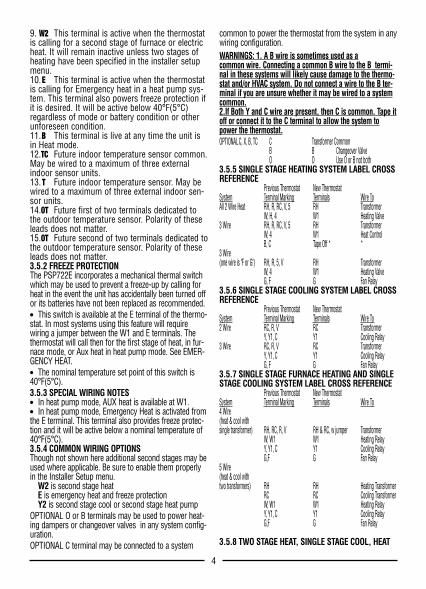
3.5.9 WIRING DIAGRAMS
5
9. W2 This terminal is active when the thermostatis calling for a second stage of furnace or electricheat. It will remain inactive unless two stages ofheating have been specified in the installer setupmenu.10.E This terminal is active when the thermostatis calling for Emergency heat in a heat pump sys-tem. This terminal also powers freeze protection ifit is desired. It will be active below 40°F(5°C)regardless of mode or battery condition or otherunforeseen condition.11.B This terminal is live at any time the unit isin Heat mode.12.TC Future indoor temperature sensor common.May be wired to a maximum of three externalindoor sensor units.13.T Future indoor temperature sensor. May bewired to a maximum of three external indoor sen-sor units.14.OT Future first of two terminals dedicated tothe outdoor temperature sensor. Polarity of theseleads does not matter.15.OT Future second of two terminals dedicated tothe outdoor temperature sensor. Polarity of theseleads does not matter.3.5.2 FREEZE PROTECTIONThe PSP722E incorporates a mechanical thermal switchwhich may be used to prevent a freeze-up by calling forheat in the event the unit has accidentally been turned offor its batteries have not been replaced as recommended.● This switch is available at the E terminal of the thermo-stat. In most systems using this feature will requirewiring a jumper between the W1 and E terminals. Thethermostat will call then for the first stage of heat, in fur-nace mode, or Aux heat in heat pump mode. See EMER-GENCY HEAT.● The nominal temperature set point of this switch is40°F(5°C).3.5.3 SPECIAL WIRING NOTES ● In heat pump mode, AUX heat is available at W1.● In heat pump mode, Emergency Heat is activated fromthe E terminal. This terminal also provides freeze protec-tion and it will be active below a nominal temperature of40°F(5°C).3.5.4 COMMON WIRING OPTIONSThough not shown here additional second stages may beused where applicable. Be sure to enable them properlyin the Installer Setup menu.
W2 is second stage heatE is emergency heat and freeze protectionY2 is second stage cool or second stage heat pump
OPTIONAL O or B terminals may be used to power heat-ing dampers or changeover valves in any system config-uration.OPTIONAL C terminal may be connected to a system
common to power the thermostat from the system in anywiring configuration. WARNINGS: 1. A B wire is sometimes used as acommon wire. Connecting a common B wire to the B termi-nal in these systems will likely cause damage to the thermo-stat and/or HVAC system. Do not connect a wire to the B ter-minal if you are unsure whether it may be wired to a systemcommon.2.If Both Y and C wire are present, then C is common. Tape itoff or connect it to the C terminal to allow the system topower the thermostat.OPTIONAL C, X, B, TC C Transformer Common
B B Changeover ValveO O Use O or B not both
3.5.5 SINGLE STAGE HEATING SYSTEM LABEL CROSSREFERENCE
Previous Thermostat New ThermostatSystem Terminal Marking Terminals Wire ToAll 2 Wire Heat RH, R, RC, V, 5 RH Transformer
W, H, 4 W1 Heating Valve3 Wire RH, R, RC, V, 5 RH Transformer
W, 4 W1 Heat ControlB, C Tape Off * *
3 Wire(one wire is "F or G") RH, R, 5, V RH Transformer
W, 4 W1 Heating ValveG, F G Fan Relay
3.5.6 SINGLE STAGE COOLING SYSTEM LABEL CROSSREFERENCE
Previous Thermostat New ThermostatSystem Terminal Marking Terminals Wire To2 Wire RC, R, V RC Transformer
Y, Y1, C Y1 Cooling Relay3 Wire RC, R, V RC Transformer
Y, Y1, C Y1 Cooling RelayG, F G Fan Relay
3.5.7 SINGLE STAGE FURNACE HEATING AND SINGLESTAGE COOLING SYSTEM LABEL CROSS REFERENCE
Previous Thermostat New ThermostatSystem Terminal Marking Terminals Wire To4 Wire (heat & cool withsingle transformer) RH, RC, R, V RH & RC, w jumper Transformer
W, W1 W1 Heating RelayY, Y1, C Y1 Cooling RelayG,F G Fan Relay
5 Wire(heat & cool withtwo transformers) RH RH Heating Transformer
RC RC Cooling Transformer W, W1 W1 Heating RelayY, Y1, C Y1 Cooling RelayG,F G Fan Relay
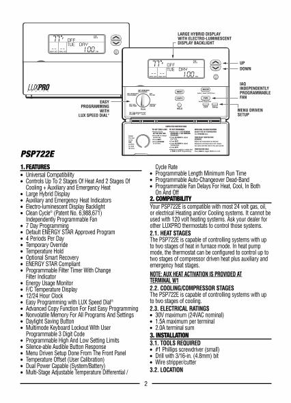
3.5.8 TWO STAGE HEAT, SINGLE STAGE COOL, HEAT
4
G O Y2 Y1 RC C RH W1 W2 E B
TYPICAL 2 WIRE HEAT HOOKUP24 VAC AND MILLIVOLT SYSTEMS
XFMR GASVALVE
AC LINE
SYSTEM TYPE = FURNACE[01]HEAT STAGES =1[02]COMPRESSOR STAGES = 0[03]MODES = Heat-Off[04]HEAT FAN CONTROL= GAS
[09]
TYPICAL INSTALLER SETUP:
OPTIONAL COMMONALLOWS USE OFSYSTEM POWER
[1]NOTES:JUMPER
PROVIDED
SYSTEMCOMMON
G O Y2 Y1 RC C RH W1 W2 E B
TYPICAL 24VAC 3 WIRE HEAT HOOKUPWHERE 3RD WIRE IS FAN WIRE
FAN XFMR GASVALVE
AC LINE
TYPICAL INSTALLER SETUP:
OPTIONAL COMMONALLOWS USE OFSYSTEM POWER
[1]NOTES:JUMPER
PROVIDED
SYSTEMCOMMON
SYSTEM TYPE = FURNACE[01]HEAT STAGES =1[02]COMPRESSOR STAGES = 0[03]MODES = Heat-Off[04]HEAT FAN CONTROL= GAS
[09]
PUMP SYSTEM LABEL CROSS REFERENCEPrevious Thermostat New Thermostat
System Terminal Marking Terminals Wire ToHeat Pump2 Heat, 1 Cool RH, RC, R, V RH & RC, w jumper Transformer
Y, Y1, C Y1 Compressor RelayW, W2 W1 Aux Heat RelayE E Em Heat/Freeze ProtB B* *Changeover ValvesO O* Use O or B not bothG,F G Fan Relay
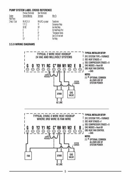
3.5.9 WIRING DIAGRAMS
5
9. W2 This terminal is active when the thermostatis calling for a second stage of furnace or electricheat. It will remain inactive unless two stages ofheating have been specified in the installer setupmenu.10.E This terminal is active when the thermostatis calling for Emergency heat in a heat pump sys-tem. This terminal also powers freeze protection ifit is desired. It will be active below 40°F(5°C)regardless of mode or battery condition or otherunforeseen condition.11.B This terminal is live at any time the unit isin Heat mode.12.TC Future indoor temperature sensor common.May be wired to a maximum of three externalindoor sensor units.13.T Future indoor temperature sensor. May bewired to a maximum of three external indoor sen-sor units.14.OT Future first of two terminals dedicated tothe outdoor temperature sensor. Polarity of theseleads does not matter.15.OT Future second of two terminals dedicated tothe outdoor temperature sensor. Polarity of theseleads does not matter.3.5.2 FREEZE PROTECTIONThe PSP722E incorporates a mechanical thermal switchwhich may be used to prevent a freeze-up by calling forheat in the event the unit has accidentally been turned offor its batteries have not been replaced as recommended.● This switch is available at the E terminal of the thermo-stat. In most systems using this feature will requirewiring a jumper between the W1 and E terminals. Thethermostat will call then for the first stage of heat, in fur-nace mode, or Aux heat in heat pump mode. See EMER-GENCY HEAT.● The nominal temperature set point of this switch is40°F(5°C).3.5.3 SPECIAL WIRING NOTES ● In heat pump mode, AUX heat is available at W1.● In heat pump mode, Emergency Heat is activated fromthe E terminal. This terminal also provides freeze protec-tion and it will be active below a nominal temperature of40°F(5°C).3.5.4 COMMON WIRING OPTIONSThough not shown here additional second stages may beused where applicable. Be sure to enable them properlyin the Installer Setup menu.
W2 is second stage heatE is emergency heat and freeze protectionY2 is second stage cool or second stage heat pump
OPTIONAL O or B terminals may be used to power heat-ing dampers or changeover valves in any system config-uration.OPTIONAL C terminal may be connected to a system
common to power the thermostat from the system in anywiring configuration. WARNINGS: 1. A B wire is sometimes used as acommon wire. Connecting a common B wire to the B termi-nal in these systems will likely cause damage to the thermo-stat and/or HVAC system. Do not connect a wire to the B ter-minal if you are unsure whether it may be wired to a systemcommon.2.If Both Y and C wire are present, then C is common. Tape itoff or connect it to the C terminal to allow the system topower the thermostat.OPTIONAL C, X, B, TC C Transformer Common
B B Changeover ValveO O Use O or B not both
3.5.5 SINGLE STAGE HEATING SYSTEM LABEL CROSSREFERENCE
Previous Thermostat New ThermostatSystem Terminal Marking Terminals Wire ToAll 2 Wire Heat RH, R, RC, V, 5 RH Transformer
W, H, 4 W1 Heating Valve3 Wire RH, R, RC, V, 5 RH Transformer
W, 4 W1 Heat ControlB, C Tape Off * *
3 Wire(one wire is "F or G") RH, R, 5, V RH Transformer
W, 4 W1 Heating ValveG, F G Fan Relay
3.5.6 SINGLE STAGE COOLING SYSTEM LABEL CROSSREFERENCE
Previous Thermostat New ThermostatSystem Terminal Marking Terminals Wire To2 Wire RC, R, V RC Transformer
Y, Y1, C Y1 Cooling Relay3 Wire RC, R, V RC Transformer
Y, Y1, C Y1 Cooling RelayG, F G Fan Relay
3.5.7 SINGLE STAGE FURNACE HEATING AND SINGLESTAGE COOLING SYSTEM LABEL CROSS REFERENCE
Previous Thermostat New ThermostatSystem Terminal Marking Terminals Wire To4 Wire (heat & cool withsingle transformer) RH, RC, R, V RH & RC, w jumper Transformer
W, W1 W1 Heating RelayY, Y1, C Y1 Cooling RelayG,F G Fan Relay
5 Wire(heat & cool withtwo transformers) RH RH Heating Transformer
RC RC Cooling Transformer W, W1 W1 Heating RelayY, Y1, C Y1 Cooling RelayG,F G Fan Relay
3.5.8 TWO STAGE HEAT, SINGLE STAGE COOL, HEAT
4
G O Y2 Y1 RC C RH W1 W2 E B
TYPICAL 2 WIRE HEAT HOOKUP24 VAC AND MILLIVOLT SYSTEMS
XFMR GASVALVE
AC LINE
SYSTEM TYPE = FURNACE[01]HEAT STAGES =1[02]COMPRESSOR STAGES = 0[03]MODES = Heat-Off[04]HEAT FAN CONTROL= GAS
[09]
TYPICAL INSTALLER SETUP:
OPTIONAL COMMONALLOWS USE OFSYSTEM POWER
[1]NOTES:JUMPER
PROVIDED
SYSTEMCOMMON
G O Y2 Y1 RC C RH W1 W2 E B
TYPICAL 24VAC 3 WIRE HEAT HOOKUPWHERE 3RD WIRE IS FAN WIRE
FAN XFMR GASVALVE
AC LINE
TYPICAL INSTALLER SETUP:
OPTIONAL COMMONALLOWS USE OFSYSTEM POWER
[1]NOTES:JUMPER
PROVIDED
SYSTEMCOMMON
SYSTEM TYPE = FURNACE[01]HEAT STAGES =1[02]COMPRESSOR STAGES = 0[03]MODES = Heat-Off[04]HEAT FAN CONTROL= GAS
[09]
76
G O Y2 Y1 RC C RH W1 W2 E B
TYPICAL 24VAC 4 WIRE HOOKUPSINGLE STAGE HEATING AND COOLING
FAN XFMRCOMPRESSOR GASVALVE
AC LINE
TYPICAL INSTALLER SETUP:
JUMPERPROVIDED
SYSTEM COMMON
SYSTEM TYPE = FURNACE[01]HEAT STAGES =1[02]COMPRESSOR STAGES = 1[03]MODES = Ht-Off-Cl-Auto[04]HEAT FAN CONTROL= GAS
[09]
OPTIONAL COMMONALLOWS USE OFSYSTEM POWER
[1]NOTES:
G O Y2 Y1 RC C RH W1 W2 E B
TYPICAL 5 WIRE HOOKUPSINGLE STAGE HEATING AND COOLING
COOLINGXFMR 1FAN GAS
VALVEHEATINGXFMR 2
AC LINE AC LINE
COOLCOMMON
COMPRESSOR
TYPICAL INSTALLER SETUP:SYSTEM TYPE = FURNACE[01]HEAT STAGES =1[02]COMPRESSOR STAGES = 1[03]MODES = Ht-Off-Cl-Auto[04]HEAT FAN CONTROL= GAS
[09]
OPTIONAL COMMONALLOWS USE OFSYSTEM POWER
[1]NOTES:
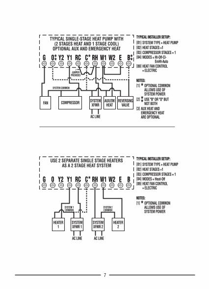
G O Y2 Y1 RC C RH W1 W2 E B
TYPICAL SINGLE-STAGE HEAT PUMP WITH(2 STAGES HEAT AND 1 STAGE COOL)
OPTIONAL AUX AND EMERGENCY HEAT
FAN SYSTEMXFMRCOMPRESSOR AUX/EM
HEATREVERSING
VALVE
AC LINE
OPTIONAL COMMONALLOWS USE OFSYSTEM POWERUSE "B" OR "O" BUTNOT BOTH
AUX HEAT ANDEMERGENCY HEATARE OPTIONAL
[1]
[2]
[3]
NOTES:
JUMPERPROVIDED
SYSTEM COMMON
TYPICAL INSTALLER SETUP:SYSTEM TYPE = HEAT PUMP[01]HEAT STAGES =1[02]COMPRESSOR STAGES = 1[03]MODES = Ht-Off-Cl-
EmHt-Auto[04]
HEAT FAN CONTROL= ELECTRIC
[09]
G O Y2 Y1 RC C RH W1 W2 E B
USE 2 SEPARATE SINGLE STAGE HEATERSAS A 2 STAGE HEAT SYSTEM
SYSTEMXFMR 1
HEATER1
HEATER2
SYSTEMXFMR 2
AC LINE AC LINE
SYSTEM 1COMMON
SYSTEM 2COMMON
OPTIONAL COMMONALLOWS USE OFSYSTEM POWER
[1]NOTES:
TYPICAL INSTALLER SETUP:SYSTEM TYPE = HEAT PUMP[01]HEAT STAGES =1[02]COMPRESSOR STAGES = 1[03]MODES = Heat-Off[04]HEAT FAN CONTROL= ELECTRIC
[09]
76
G O Y2 Y1 RC C RH W1 W2 E B
TYPICAL 24VAC 4 WIRE HOOKUPSINGLE STAGE HEATING AND COOLING
FAN XFMRCOMPRESSOR GASVALVE
AC LINE
TYPICAL INSTALLER SETUP:
JUMPERPROVIDED
SYSTEM COMMON
SYSTEM TYPE = FURNACE[01]HEAT STAGES =1[02]COMPRESSOR STAGES = 1[03]MODES = Ht-Off-Cl-Auto[04]HEAT FAN CONTROL= GAS
[09]
OPTIONAL COMMONALLOWS USE OFSYSTEM POWER
[1]NOTES:
G O Y2 Y1 RC C RH W1 W2 E B
TYPICAL 5 WIRE HOOKUPSINGLE STAGE HEATING AND COOLING
COOLINGXFMR 1FAN GAS
VALVEHEATINGXFMR 2
AC LINE AC LINE
COOLCOMMON
COMPRESSOR
TYPICAL INSTALLER SETUP:SYSTEM TYPE = FURNACE[01]HEAT STAGES =1[02]COMPRESSOR STAGES = 1[03]MODES = Ht-Off-Cl-Auto[04]HEAT FAN CONTROL= GAS
[09]
OPTIONAL COMMONALLOWS USE OFSYSTEM POWER
[1]NOTES:
G O Y2 Y1 RC C RH W1 W2 E B
TYPICAL SINGLE-STAGE HEAT PUMP WITH(2 STAGES HEAT AND 1 STAGE COOL)
OPTIONAL AUX AND EMERGENCY HEAT
FAN SYSTEMXFMRCOMPRESSOR AUX/EM
HEATREVERSING
VALVE
AC LINE
OPTIONAL COMMONALLOWS USE OFSYSTEM POWERUSE "B" OR "O" BUTNOT BOTH
AUX HEAT ANDEMERGENCY HEATARE OPTIONAL
[1]
[2]
[3]
NOTES:
JUMPERPROVIDED
SYSTEM COMMON
TYPICAL INSTALLER SETUP:SYSTEM TYPE = HEAT PUMP[01]HEAT STAGES =1[02]COMPRESSOR STAGES = 1[03]MODES = Ht-Off-Cl-
EmHt-Auto[04]
HEAT FAN CONTROL= ELECTRIC
[09]
G O Y2 Y1 RC C RH W1 W2 E B
USE 2 SEPARATE SINGLE STAGE HEATERSAS A 2 STAGE HEAT SYSTEM
SYSTEMXFMR 1
HEATER1
HEATER2
SYSTEMXFMR 2
AC LINE AC LINE
SYSTEM 1COMMON
SYSTEM 2COMMON
OPTIONAL COMMONALLOWS USE OFSYSTEM POWER
[1]NOTES:
TYPICAL INSTALLER SETUP:SYSTEM TYPE = HEAT PUMP[01]HEAT STAGES =1[02]COMPRESSOR STAGES = 1[03]MODES = Heat-Off[04]HEAT FAN CONTROL= ELECTRIC
[09]
3.6. INSTALL BATTERIESInstall batteries at this time. For instructions, see BAT-TERY INSTALLATION.3.7. INSTALLER SETUPConfiguration items are selected from the Installer Set upMenu. They are stored in non-volatile RAM, and will bepreserved even in the event that the unit’s batteries arerun down, or removed, or the hardware reset on the rearof the unit’s circuit board of the thermostat is pressed.NOTE: Pressing the S/W RESET button on the rear of theunit’s circuit board will write default values of all temperatureprograms and setup menus into the unit nonvolatile memory.Take care not to inadvertently press this button when the ther-mostat has been removed from the wall plate!
3.7.1 ACCESS AND NAVIGATE INSTALLER SETUPMENUNote: Insure that all relays are off before making changes inthe installer menu. There are two methods, which may beused to do this. Place the unit in the OFF mode and wait for 5minutes or Press the H/W RESET button on the rear of theunit’s circuit board. Take care not to inadvertently press theS/W RESET button.● To enter the Installer Setup Menu press and hold theSetup Button for 10 seconds.● Use the NEXT button to scroll through its options. Asyou proceed the menu item number will be displayed inthe left portion of the screen.● Selections can be changed by pressing the UP/DOWNbutton.● Moving from one menu item to the next and accept-ance of changes is done by pressing the NEXT button.● All changes become effective when the unit exits theInstaller Setup mode.● The Installer Setup mode will be exited when the Setupbutton is pressed again, or, if no other keys are pressedfor 20 seconds. All settings, their choices and default values are given inINSTALLER SETUP MENU WITH FURNACE SYSTEMTYPE SELECTED: and INSTALLER SETUP MENU WITHHEAT PUMP SYSTEM TYPE SELECTED AND FUTUREOUTDOOR SENSOR ENABLED.3.7.1.1 SYSTEM TYPEThis option determines whether the thermostat is to con-trol a furnace and air conditioning system or heat pumpsystem.● In furnace mode the unit will make the proper W ter-minals live for Heating, and the proper Y terminals livefor cooling.● In Heat Pump mode the unit makes the proper Y ter-minals live for the first and second stages of a heat pumpunit during heating or cooling. In this mode an additionalstage of Aux Heat may also be activated through the W1terminal.
3.7.1.2 HEAT STAGESSet this to the number of non-compressor driven heatstages to use for temperature control by this system.3.7.1.3 COMPRESSOR STAGES (COOL/HEAT PUMPSTAGES)Set the number of compressor driven system stages touse for temperature control. These stages include allcooling or heat pump stages to be used for temperaturecontrol by this system.3.7.1.4 MODESThe modes setting selects what system modes will beavailable to the user. The selections available are systemmode dependant:● Heat-Off● Cool-Off● Heat-Off-Cool● Heat-Off-Cool-Auto (Furnace Mode) or● Heat-Off-Cool-Em Heat-Auto (Heat Pump Mode)
3.7.1.5 MINIMUM RUN TIMEMinimum Run Time provides compressor protection andprevents short cycling. Compressor stages are held offfor a minimum of this time. During program run this isalso the minimum on time.3.7.1.6 HEAT PUMP LOCKOUTThis menu item is available only in Heat Pump Mode withan operational outdoor temperature sensor. Enabling thisoption allows the thermostat to disable a heat pump andrequest AUX Heat below the Heat Pump LockoutTemperature.3.7.1.7 HEAT PUMP LOCKOUT TEMPERATUREThis menu item is available only in Heat Pump Mode withan operational outdoor temperature sensor. With it youmay set the outdoor temperature at which the thermostatwill cease to call for heat pump sourced heat, and use thealternate AUX Heat source.3.7.1.8 DEADBANDWhen using auto-changeover, deadband provides a disal-lowed temperature range between the maximum heattemperature set point and minimum cool temperature setpoint. Deadband may be set from 3 to 5 degrees. Withauto-changeover active and the Deadband set to 3°F andheat set to 70°F the minimum allowed cool temperatureset point will be 73°F. If the cool temperature set point islowered, then the heat temperature set point will be low-ered by the same amount maintaining the 3°F Deadband.3.7.1.9 SWING 1Swing 1 sets the temperature variation the system allowsabove the temperature set point before switching the firststage heat source off, or below the temperature set pointbefore switching the first stage heat source on. In Cool,Swing 1 sets the temperature variation the system allowsabove the temperature set point before switching firststage of cooling on, or below the temperature set pointbefore switching the first stage of cooling off.
98
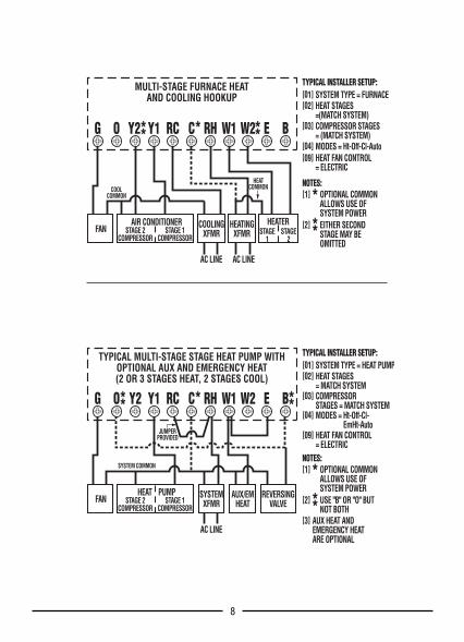
G O Y2 Y1 RC C RH W1 W2 E B
MULTI-STAGE FURNACE HEATAND COOLING HOOKUP
FAN COOLINGXFMR
HEATINGXFMR
HEATERAIR CONDITIONERSTAGE 2
COMPRESSORSTAGE 1
COMPRESSOR
AC LINE AC LINE
OPTIONAL COMMONALLOWS USE OFSYSTEM POWEREITHER SECONDSTAGE MAY BE OMITTED
[1]
[2]
NOTES:
STAGE1
STAGE2
COOLCOMMON
HEATCOMMON
TYPICAL INSTALLER SETUP:SYSTEM TYPE = FURNACE[01]HEAT STAGES=(MATCH SYSTEM)
[02]
COMPRESSOR STAGES= (MATCH SYSTEM)
[03]
MODES = Ht-Off-Cl-Auto[04]HEAT FAN CONTROL= ELECTRIC
[09]
G O Y2 Y1 RC C RH W1 W2 E B
TYPICAL MULTI-STAGE STAGE HEAT PUMP WITHOPTIONAL AUX AND EMERGENCY HEAT(2 OR 3 STAGES HEAT, 2 STAGES COOL)
FAN SYSTEMXFMR
AUX/EMHEAT
REVERSINGVALVE
HEAT PUMPSTAGE 2
COMPRESSORSTAGE 1
COMPRESSOR
AC LINE
JUMPERPROVIDED
SYSTEM COMMON OPTIONAL COMMONALLOWS USE OFSYSTEM POWERUSE "B" OR "O" BUTNOT BOTH
AUX HEAT ANDEMERGENCY HEATARE OPTIONAL
[1]
[2]
[3]
NOTES:
TYPICAL INSTALLER SETUP:SYSTEM TYPE = HEAT PUMP[01]HEAT STAGES= MATCH SYSTEM
[02]
COMPRESSOR STAGES = MATCH SYSTEM
[03]
MODES = Ht-Off-Cl- EmHt-Auto
[04]
HEAT FAN CONTROL= ELECTRIC
[09]
3.6. INSTALL BATTERIESInstall batteries at this time. For instructions, see BAT-TERY INSTALLATION.3.7. INSTALLER SETUPConfiguration items are selected from the Installer Set upMenu. They are stored in non-volatile RAM, and will bepreserved even in the event that the unit’s batteries arerun down, or removed, or the hardware reset on the rearof the unit’s circuit board of the thermostat is pressed.NOTE: Pressing the S/W RESET button on the rear of theunit’s circuit board will write default values of all temperatureprograms and setup menus into the unit nonvolatile memory.Take care not to inadvertently press this button when the ther-mostat has been removed from the wall plate!
3.7.1 ACCESS AND NAVIGATE INSTALLER SETUPMENUNote: Insure that all relays are off before making changes inthe installer menu. There are two methods, which may beused to do this. Place the unit in the OFF mode and wait for 5minutes or Press the H/W RESET button on the rear of theunit’s circuit board. Take care not to inadvertently press theS/W RESET button.● To enter the Installer Setup Menu press and hold theSetup Button for 10 seconds.● Use the NEXT button to scroll through its options. Asyou proceed the menu item number will be displayed inthe left portion of the screen.● Selections can be changed by pressing the UP/DOWNbutton.● Moving from one menu item to the next and accept-ance of changes is done by pressing the NEXT button.● All changes become effective when the unit exits theInstaller Setup mode.● The Installer Setup mode will be exited when the Setupbutton is pressed again, or, if no other keys are pressedfor 20 seconds. All settings, their choices and default values are given inINSTALLER SETUP MENU WITH FURNACE SYSTEMTYPE SELECTED: and INSTALLER SETUP MENU WITHHEAT PUMP SYSTEM TYPE SELECTED AND FUTUREOUTDOOR SENSOR ENABLED.3.7.1.1 SYSTEM TYPEThis option determines whether the thermostat is to con-trol a furnace and air conditioning system or heat pumpsystem.● In furnace mode the unit will make the proper W ter-minals live for Heating, and the proper Y terminals livefor cooling.● In Heat Pump mode the unit makes the proper Y ter-minals live for the first and second stages of a heat pumpunit during heating or cooling. In this mode an additionalstage of Aux Heat may also be activated through the W1terminal.
3.7.1.2 HEAT STAGESSet this to the number of non-compressor driven heatstages to use for temperature control by this system.3.7.1.3 COMPRESSOR STAGES (COOL/HEAT PUMPSTAGES)Set the number of compressor driven system stages touse for temperature control. These stages include allcooling or heat pump stages to be used for temperaturecontrol by this system.3.7.1.4 MODESThe modes setting selects what system modes will beavailable to the user. The selections available are systemmode dependant:● Heat-Off● Cool-Off● Heat-Off-Cool● Heat-Off-Cool-Auto (Furnace Mode) or● Heat-Off-Cool-Em Heat-Auto (Heat Pump Mode)
3.7.1.5 MINIMUM RUN TIMEMinimum Run Time provides compressor protection andprevents short cycling. Compressor stages are held offfor a minimum of this time. During program run this isalso the minimum on time.3.7.1.6 HEAT PUMP LOCKOUTThis menu item is available only in Heat Pump Mode withan operational outdoor temperature sensor. Enabling thisoption allows the thermostat to disable a heat pump andrequest AUX Heat below the Heat Pump LockoutTemperature.3.7.1.7 HEAT PUMP LOCKOUT TEMPERATUREThis menu item is available only in Heat Pump Mode withan operational outdoor temperature sensor. With it youmay set the outdoor temperature at which the thermostatwill cease to call for heat pump sourced heat, and use thealternate AUX Heat source.3.7.1.8 DEADBANDWhen using auto-changeover, deadband provides a disal-lowed temperature range between the maximum heattemperature set point and minimum cool temperature setpoint. Deadband may be set from 3 to 5 degrees. Withauto-changeover active and the Deadband set to 3°F andheat set to 70°F the minimum allowed cool temperatureset point will be 73°F. If the cool temperature set point islowered, then the heat temperature set point will be low-ered by the same amount maintaining the 3°F Deadband.3.7.1.9 SWING 1Swing 1 sets the temperature variation the system allowsabove the temperature set point before switching the firststage heat source off, or below the temperature set pointbefore switching the first stage heat source on. In Cool,Swing 1 sets the temperature variation the system allowsabove the temperature set point before switching firststage of cooling on, or below the temperature set pointbefore switching the first stage of cooling off.
98
G O Y2 Y1 RC C RH W1 W2 E B
MULTI-STAGE FURNACE HEATAND COOLING HOOKUP
FAN COOLINGXFMR
HEATINGXFMR
HEATERAIR CONDITIONERSTAGE 2
COMPRESSORSTAGE 1
COMPRESSOR
AC LINE AC LINE
OPTIONAL COMMONALLOWS USE OFSYSTEM POWEREITHER SECONDSTAGE MAY BE OMITTED
[1]
[2]
NOTES:
STAGE1
STAGE2
COOLCOMMON
HEATCOMMON
TYPICAL INSTALLER SETUP:SYSTEM TYPE = FURNACE[01]HEAT STAGES=(MATCH SYSTEM)
[02]
COMPRESSOR STAGES= (MATCH SYSTEM)
[03]
MODES = Ht-Off-Cl-Auto[04]HEAT FAN CONTROL= ELECTRIC
[09]
G O Y2 Y1 RC C RH W1 W2 E B
TYPICAL MULTI-STAGE STAGE HEAT PUMP WITHOPTIONAL AUX AND EMERGENCY HEAT(2 OR 3 STAGES HEAT, 2 STAGES COOL)
FAN SYSTEMXFMR
AUX/EMHEAT
REVERSINGVALVE
HEAT PUMPSTAGE 2
COMPRESSORSTAGE 1
COMPRESSOR
AC LINE
JUMPERPROVIDED
SYSTEM COMMON OPTIONAL COMMONALLOWS USE OFSYSTEM POWERUSE "B" OR "O" BUTNOT BOTH
AUX HEAT ANDEMERGENCY HEATARE OPTIONAL
[1]
[2]
[3]
NOTES:
TYPICAL INSTALLER SETUP:SYSTEM TYPE = HEAT PUMP[01]HEAT STAGES= MATCH SYSTEM
[02]
COMPRESSOR STAGES = MATCH SYSTEM
[03]
MODES = Ht-Off-Cl- EmHt-Auto
[04]
HEAT FAN CONTROL= ELECTRIC
[09]
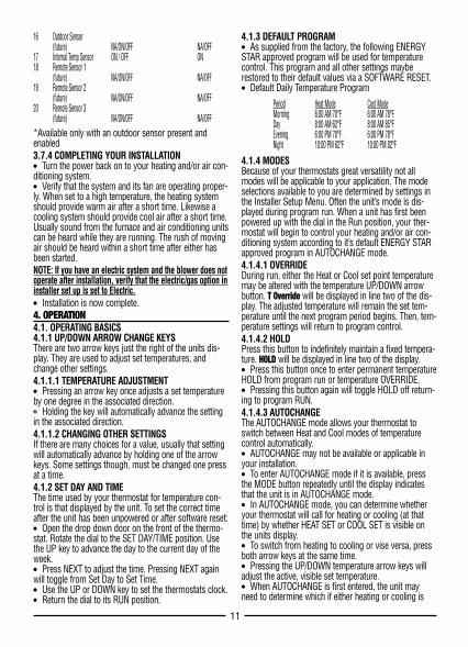
16 Outdoor Sensor(future) NA/ON/OFF NA/OFF
17 Internal Temp Sensor ON / OFF ON18 Remote Sensor 1
(future) NA/ON/OFF NA/OFF19 Remote Sensor 2
(future) NA/ON/OFF NA/OFF20 Remote Sensor 3
(future) NA/ON/OFF NA/OFF*Available only with an outdoor sensor present andenabled3.7.4 COMPLETING YOUR INSTALLATION● Turn the power back on to your heating and/or air con-ditioning system.● Verify that the system and its fan are operating proper-ly. When set to a high temperature, the heating systemshould provide warm air after a short time. Likewise acooling system should provide cool air after a short time.Usually sound from the furnace and air conditioning unitscan be heard while they are running. The rush of movingair should be heard within a short time after either hasbeen started.NOTE: If you have an electric system and the blower does notoperate after installation, verify that the electric/gas option ininstaller set up is set to Electric.● Installation is now complete.4. OPERATION4.1. OPERATING BASICS4.1.1 UP/DOWN ARROW CHANGE KEYSThere are two arrow keys just the right of the units dis-play. They are used to adjust set temperatures, andchange other settings. 4.1.1.1 TEMPERATURE ADJUSTMENT● Pressing an arrow key once adjusts a set temperatureby one degree in the associated direction.❷ Holding the key will automatically advance the settingin the associated direction.4.1.1.2 CHANGING OTHER SETTINGSIf there are many choices for a value, usually that settingwill automatically advance by holding one of the arrowkeys. Some settings though, must be changed one pressat a time.4.1.2 SET DAY AND TIMEThe time used by your thermostat for temperature con-trol is that displayed by the unit. To set the correct timeafter the unit has been unpowered or after software reset:● Open the drop down door on the front of the thermo-stat. Rotate the dial to the SET DAY/TIME position. Usethe UP key to advance the day to the current day of theweek.● Press NEXT to adjust the time. Pressing NEXT againwill toggle from Set Day to Set Time.● Use the UP or DOWN key to set the thermostats clock.● Return the dial to its RUN position.
4.1.3 DEFAULT PROGRAM● As supplied from the factory, the following ENERGYSTAR approved program will be used for temperaturecontrol. This program and all other settings mayberestored to their default values via a SOFTWARE RESET.● Default Daily Temperature Program
Period Heat Mode Cool ModeMorning 6:00 AM 70°F 6:00 AM 78°FDay 8:00 AM 62°F 8:00 AM 85°FEvening 6:00 PM 70°F 6:00 PM 78°FNight 10:00 PM 62°F 10:00 PM 82°F
4.1.4 MODESBecause of your thermostats great versatility not allmodes will be applicable to your application. The modeselections available to you are determined by settings inthe Installer Setup Menu. Often the unit’s mode is dis-played during program run. When a unit has first beenpowered up with the dial in the Run position, your ther-mostat will begin to control your heating and/or air con-ditioning system according to it’s default ENERGY STARapproved program in AUTOCHANGE mode.4.1.4.1 OVERRIDEDuring run, either the Heat or Cool set point temperaturemay be altered with the temperature UP/DOWN arrowbutton. T Override will be displayed in line two of the dis-play. The adjusted temperature will remain the set tem-perature until the next program period begins. Then, tem-perature settings will return to program control.4.1.4.2 HOLDPress this button to indefinitely maintain a fixed tempera-ture. HOLD will be displayed in line two of the display.● Press this button once to enter permanent temperatureHOLD from program run or temperature OVERRIDE.● Pressing this button again will toggle HOLD off return-ing to program RUN.4.1.4.3 AUTOCHANGEThe AUTOCHANGE mode allows your thermostat toswitch between Heat and Cool modes of temperaturecontrol automatically.● AUTOCHANGE may not be available or applicable inyour installation.● To enter AUTOCHANGE mode if it is available, pressthe MODE button repeatedly until the display indicatesthat the unit is in AUTOCHANGE mode.● In AUTOCHANGE mode, you can determine whetheryour thermostat will call for heating or cooling (at thattime) by whether HEAT SET or COOL SET is visible onthe units display.● To switch from heating to cooling or vise versa, pressboth arrow keys at the same time.● Pressing the UP/DOWN temperature arrow keys willadjust the active, visible set temperature.● When AUTOCHANGE is first entered, the unit mayneed to determine which if either heating or cooling is
11
3.7.1.10 SWING 2This value is similar to the Swing 1, but it controls thetemperature variation the system allows above and belowSwing 1’s lower limit before calling for a second stage.Once a second stage is activated, it will remain on untilthe temperature set point has been reached. If a thirdstage of heat is present in heat pump mode, Swing 2 isused to control it from the stage 2 lower limit.3.7.1.11 HEAT FAN CONTROLFossil fuel furnaces normally control the system fan whilethe furnace is operating. Electric systems normallyrequire the thermostat to activate the fan. This settinginstructs the thermostat how to handle fan control duringheating. Electric heat and heat pumps generally requirethe thermostat to activate the fan and therefore use theelectric setting.3.7.1.12 HEAT FAN ON DELAYThis setting allows the installer to program the length oftime between heating activation and fan activation (delayon make). 3.7.1.13 HEAT FAN OFF DELAYThis setting allows the installer to program the length oftime between heating deactivation and fan deactivation(delay on break).3.7.1.14 COOL FAN ON DELAYThis setting allows the installer to program the length oftime between cooling activation and fan activation (delayon make). 3.7.1.15 COOL FAN OFF DELAYThis setting allows the installer to program the length oftime between cooling deactivation and fan deactivation(delay on break). 3.7.1.16 FUTURE OUTDOOR SENSORThis setting enables and disables an outdoor sensor if itis present. The setting will be held NA if a sensor is notpresent, and will be reset to NA If the sensor is discon-nected for any reason, including removal of the thermo-stat from its base-plate, the thermostat will automaticallydisable the sensor changing the setting in this menufrom ON to NA. With an outdoor sensor present andenabled, the outdoor temperature will be displayed alter-nately with time. The word OUT will be visible to the rightof the temperature while the outside temperature is dis-played.3.7.1.17 INTERNAL TEMPERATURE SENSORThis setting enables and disables the thermostats internaltemperature sensor. It may only be disabled if there areindoor remote sensors present and enabled.3.7.1.18 FUTURE INDOOR REMOTE SENSOR 1, 2, 3Used to enable and disable the respective remote sensorsin a system. When more than one indoor sensor is used,the values of their measurements are averaged for use intemperature control.
3.7.2 INSTALLER SETUP MENU WITH FURNACE SYS-TEM TYPE SELECTED:MenuItem Display Selections Default01 System Type Furnace / Heat Pump Furnace02 Heat Stages 0 – 2 203 Compressor Stages 0 – 2 204 Modes Heat-Off *
Cool-Off *Heat-Off-Cool *Heat-Off-Cool-Auto *Heat-Off-
Cool-Auto05 Minimum Run Time 1 to 5 min 4 min06 Deadband 3°F(1°C) to 5°F(3°C) 3°F(1°C)07 Swing 1 0.25°F(0.15°C) to 2.25°F(1.25°C) 0.25°F(0.15°C)08 Swing 2 0.25°F(0.15°C) to 2.25°F(1.25°C) 0.5°F(0.3°C)09 Heat Fan Control Gas / Electric Gas10 Heat Fan On Delay 0, 15, 30…180 sec 0 sec11 Heat Fan Off Delay 0, 15, 30…180 sec 0 sec12 Cool Fan On Delay 0, 15, 30…180 sec 0 sec13 Cool Fan Off Delay 0, 15, 30…180 sec 0 sec14 Outdoor Sensor (future) NA/ON/OFF NA/OFF15 Internal Temp Sensor
(future) ON/OFF ON16 Remote Sensor 1
(future) NA/ON/OFF NA/OFF17 Remote Sensor 2
(future) NA/ON/OFF NA/OFF18 Remote Sensor 3
(future) NA/ON/OFF NA/OFF
3.7.3 INSTALLER SETUP MENU WITH HEAT PUMPSYSTEM TYPE SELECTED AND OUTDOOR FUTURESENSOR ENABLED:MenuItem Display Selections Default01 System Type Furnace / Heat Pump Furnace02 Heat Stages 0 – 1 103 Compressor Stages 0 – 2 104 Modes Heat-Off *
Cool-Off *Heat-Off-Cool *Heat-Off-Cool- *Heat-Off-Cool-Em Heat-Auto Em Heat-Auto
05 Minimum Run Time 1 to 5 min 4 min06* Heat Pump Lockout ON, OFF Off07* Heat Pump
Lockout Temperature 0°F- 50°F(-17°C-10°C) 0°F(-17°C)08 Deadband 3°F(1°C) to 5°F(3°C) 3°F(1°C)09 Swing 1 0.25°F(0.15°C) to 2.25°F(1.25°C) 0.25°F(0.15°C)10 Swing 2 0.25°F(0.15°C) to 2.25°F(1.25°C) 0.5°F(0.3°C)11 Heat Fan Control Electric Electric12 Heat Fan On Delay 0, 15, 30…180 sec 0 sec13 Heat Fan Off Delay 0, 15, 30…180 sec 0 sec14 Cool Fan On Delay 0, 15, 30…180 sec 0 sec15 Cool Fan Off Delay 0, 15, 30…180 sec 0 sec
10
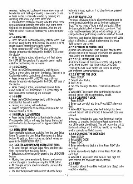
4.2.4 TEMPERATURE DISPLAY FORMAT (F/C DISPLAY)Temperature may be displayed in Fahrenheit or Celsiuswith this option.4.2.5 CLOCK FORMATThe time shown on the thermostats clock may be dis-played in 12 or 24 hour format. Set this option to yourpreference.4.2.6 CALIBRATION OFFSETYour thermostat is accurately calibrated at the factory towithin ±1°F An offset value up to ±5°F may be added tothe temperature value that the thermostat measures. Thismay allow you to match this thermostat to another.4.2.7 MAXIMUM HEAT SETTINGThe temperature that this option is set to will be the high-est HEAT SET temperature available in run mode or whileprogramming the thermostat.4.2.8 MINIMUM COOL SETTINGThe temperature that this option is set to will be the low-est COOL SET temperature available in run mode or whileprogramming the thermostat.4.2.9 SMART RECOVERYYour thermostats Smart Recovery allows your HVAC sys-tem to attempt to recover from a setback period andreach your desired comfort temperature set point by thebeginning of your programmed comfort period. Thisoption allows you to choose whether to use SmartRecovery.If enabled, Smart Recovery will initiate if:● Recovery is valid only from a night setback to morningcomfort or day setback to evening comfort period.● In Heat mode the temperature set point of the comfortperiod must be higher than the setback period.● In Cool mode the temperature set point of the comfortperiod must be lower than the setback period.● The estimated Smart recovery time must be longerthan 15 minutes for an Smart recovery to be initiated.● Maximum Smart recovery time is one hour.● AUX heat will not be activated during the first half hourof a Smart recovery. Then it will only be activated if nec-essary to achieve the programmed temperature by thebeginning of the next period.● The Smart recovery temperature set point must beachievable. If a desired smart recovery is repeatedlyignored by your thermostat that is an indicator that youshould modify your program so that the recovery can beachieved within the 1 hour limit.● A Smart recovery may not be initiated for 48 hoursafter the units programs have been changed. This allowsthe unit to gather the data necessary to predict a Smartrecovery time.4.2.10 FILTER LIMITYour thermostat will warn you that your HVAC systemsair filter should be changed after the systems fan has runthe number of hours that this setting has been pro-
grammed for. A general rule of thumb is to assume thatthe fan will run at 1/3 duty cycle. A 90 day filter will thenbe good for 90*24/3=720 hours. This is the default value.Setting the filter counter limit to 0000 will disable thechange filter indicator. Valid entries are from 0 to2000hrs.4.2.11 USER SETUP MENU:Menu Item Display Selections Default01 LOCK KEYPAD NO, PARTIAL, FULL, NEW CODE NO02 BEEP ON, OFF ON03 °F/°C DISPLAY °F, °C °F04 CLOCK FORMAT 12HR / 24HR 12HR05 CALIBRATION OFFSET ±5°F (±3°C) 0°F06 MAX HEAT TEMP 45°F-90°F (7°C-32°C) 90°F (32°C)07 MIN HEAT TEMP 45°F-90°F (7°C-32°C) 45°F (7°C)08 EARLY RECOVERY ON, OFF OFF09 FILTER LIMIT 0-2000HRS 720HRS
4.3. ADVANCED FEATURES AND OPERATION4.3.1 EMERGENCY HEAT● To use an emergency heat system, press the MODEbutton repeatedly until the EMER HT is shown along thetop of the display. The unit is in emergency heat modeready to control your emergency heating system. In heatpump systems, the emergency heat terminal is oftenwired to W1 the AUX heat terminal.● Press temperature UP or DOWN keys until yourdesired temperature is displayed in the HEAT SET area ofthe display.● Freeze protection is also provided at this terminal. SeeFREEZE PROTECTION.4.3.2 FAN MODESYour thermostat provides three fan modes. They areAUTO, CLEAN, and ON. The fan may be controlled byyour units program, or the program may be overriddenby pressing the FAN button and selecting another mode.Appropriate indicators are visible along the top of theunits display when active.4.3.2.1 FAN AUTOFAN AUTO denotes that the fan will run only to fulfill yourheating and cooling requirements.4.3.2.2 CLEANThis enables the CLEAN CYCLE® feature. The FAN iconalone in the display denotes that the fan is maintainingthe programmed minimum run time; it will also run addi-tional time as required to maintain temperature control.The algorithm used avoids additional fan time when theminimum run time has been met over the last hourthrough temperature control. Minimum fan run times aremet by running one third the hourly requirement at twen-ty minute intervals.4.3.2.3 FAN ON FAN ON denotes that your system fan will run continu-ously.
13
required. Heating and cooling set temperatures may notbe adjusted until heating or cooling is necessary, or oneof these modes is manually selected by pressing andreleasing both arrow keys at the same time.● You can force heating or cooling to be the active modeby pressing and releasing both arrow keys at the sametime until the desired mode is indicated. After, the unitwill then switch modes as necessary to control tempera-ture.4.1.4.4 HEATING● Press the MODE button repeatedly until the word HEATis shown along the top of the display. The unit is in HEATmode ready to control your heating system. ● Press temperature UP or DOWN keys until yourdesired temperature is displayed in the HEAT SET area ofthe display.● While heating is active, a flame icon will flash abovethe HEAT SET temperature. If a second stage of heat iscalled for the flashing rate increases.4.1.4.5 COOLING● Press the MODE button repeatedly until the wordCOOL is shown along the top of the display. The unit is inCool mode ready to control your air conditioner. ● Press temperature UP or DOWN keys until yourdesired temperature is displayed in the COOL SET area ofthe display.● While cooling is active, a snowflake icon will flashabove the COOL SET temperature. If a second stage ofheat is called for the flashing rate increases.4.1.4.6 OFF● Press the MODE button repeatedly until the displayindicates that the unit is in OFF.● Heating and cooling will be disabled.● Periods programmed to maintain a minimum fan runtime will continue do so.4.1.5 DISPLAY ILLUMINATION● Press the light bulb button to illuminate the display.Pressing other buttons will keep the display illuminateduntil no button has been pressed for approximately 20seconds.4.2. USER SETUP MENUUser selectable options are available from the User SetupMenu. To access the User Setup Menu press the Setupbutton. All settings, their choices and default values aregiven in the USER SETUP MENU:. 4.2.1 ACCESS AND NAVIGATE USER SETUP MENU● To scroll through the User Setup Menu one item at atime, momentarily press Setup Button.● Selections can be changed by pressing the UP/DOWNbutton.● Moving from one menu item to the next and accept-ance of changes is done by pressing the NEXT button.● All changes become effective when the unit exits theUser Setup mode.● The User Setup mode will be exited when the Setup
button is pressed again, or if no other keys are pressedfor 20 seconds.4.2.2 KEYBOARD LOCKTwo types of Keyboard locks allow owners/operators toprevent unauthorized changes to the thermostats set-tings. The two types of locks are full and partial. Whenthe thermostat is locked, a three digit code is set. Thatcode must be reentered before locked settings can bechanged without performing a software reset off the unit.Entering a code toggles the selected lock on or off. Whilea lock is effective, a padlock is shown near the lowerright corner of the screen.4.2.2.1 PARTIAL KEYBOARD LOCKA partial lock allows other users to adjust only the tem-perature set point to values at or between the MaximumHeat Setting and Minimum Cool Settings.4.2.2.2 FULL KEYBOARD LOCKA full lock disables all the keys except the Setup buttonon the front, and the S/W Reset button on the rear.Pressing the S/W Reset button will rewrite all settingsand programs to their default values. 4.2.2.3 SETTING THE LOCK1. Press SETUP.2. Select Full or Partial.3. Press NEXT.4. Set code one digit at a time. Press NEXT after eachdigit.5. When NEXT is pressed after the third digit has been entered, the unit will be appropriately locked.4.2.2.4 CLEARING A LOCK1. Press SETUP.2. Enter code one digit at a time. Press NEXT after eachdigit.3. When NEXT is pressed after the third digit has beenentered, the unit will be unlocked if the correct code wasentered.If you have forgotten the code, your thermostat may beunlocked by pressing the Software Reset button on therear of the unit's circuit board. This will restore the unit toits default settings and it will likely need to be reconfig-ured to control your HVAC system.4.2.2.5 CHANGING THE LOCK CODE 1. Press SETUP. 2. Select NEW CODE. 3. Press NEXT. 4. Enter old code one digit at a time. Press NEXT aftereach digit. 5. Enter new code one digit at a time. Press NEXT aftereach digit. 6. When NEXT is pressed after the new third digit hasbeen entered, the new code will be effective.4.2.3 BEEPThis option allows the audible feedback tone (Beep) to beenabled or disabled.
12
Kurt
Rectangle
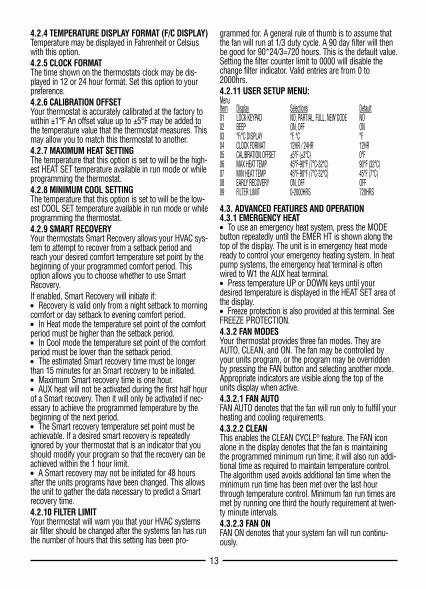
4.2.4 TEMPERATURE DISPLAY FORMAT (F/C DISPLAY)Temperature may be displayed in Fahrenheit or Celsiuswith this option.4.2.5 CLOCK FORMATThe time shown on the thermostats clock may be dis-played in 12 or 24 hour format. Set this option to yourpreference.4.2.6 CALIBRATION OFFSETYour thermostat is accurately calibrated at the factory towithin ±1°F An offset value up to ±5°F may be added tothe temperature value that the thermostat measures. Thismay allow you to match this thermostat to another.4.2.7 MAXIMUM HEAT SETTINGThe temperature that this option is set to will be the high-est HEAT SET temperature available in run mode or whileprogramming the thermostat.4.2.8 MINIMUM COOL SETTINGThe temperature that this option is set to will be the low-est COOL SET temperature available in run mode or whileprogramming the thermostat.4.2.9 SMART RECOVERYYour thermostats Smart Recovery allows your HVAC sys-tem to attempt to recover from a setback period andreach your desired comfort temperature set point by thebeginning of your programmed comfort period. Thisoption allows you to choose whether to use SmartRecovery.If enabled, Smart Recovery will initiate if:● Recovery is valid only from a night setback to morningcomfort or day setback to evening comfort period.● In Heat mode the temperature set point of the comfortperiod must be higher than the setback period.● In Cool mode the temperature set point of the comfortperiod must be lower than the setback period.● The estimated Smart recovery time must be longerthan 15 minutes for an Smart recovery to be initiated.● Maximum Smart recovery time is one hour.● AUX heat will not be activated during the first half hourof a Smart recovery. Then it will only be activated if nec-essary to achieve the programmed temperature by thebeginning of the next period.● The Smart recovery temperature set point must beachievable. If a desired smart recovery is repeatedlyignored by your thermostat that is an indicator that youshould modify your program so that the recovery can beachieved within the 1 hour limit.● A Smart recovery may not be initiated for 48 hoursafter the units programs have been changed. This allowsthe unit to gather the data necessary to predict a Smartrecovery time.4.2.10 FILTER LIMITYour thermostat will warn you that your HVAC systemsair filter should be changed after the systems fan has runthe number of hours that this setting has been pro-
grammed for. A general rule of thumb is to assume thatthe fan will run at 1/3 duty cycle. A 90 day filter will thenbe good for 90*24/3=720 hours. This is the default value.Setting the filter counter limit to 0000 will disable thechange filter indicator. Valid entries are from 0 to2000hrs.4.2.11 USER SETUP MENU:Menu Item Display Selections Default01 LOCK KEYPAD NO, PARTIAL, FULL, NEW CODE NO02 BEEP ON, OFF ON03 °F/°C DISPLAY °F, °C °F04 CLOCK FORMAT 12HR / 24HR 12HR05 CALIBRATION OFFSET ±5°F (±3°C) 0°F06 MAX HEAT TEMP 45°F-90°F (7°C-32°C) 90°F (32°C)07 MIN HEAT TEMP 45°F-90°F (7°C-32°C) 45°F (7°C)08 EARLY RECOVERY ON, OFF OFF09 FILTER LIMIT 0-2000HRS 720HRS
4.3. ADVANCED FEATURES AND OPERATION4.3.1 EMERGENCY HEAT● To use an emergency heat system, press the MODEbutton repeatedly until the EMER HT is shown along thetop of the display. The unit is in emergency heat modeready to control your emergency heating system. In heatpump systems, the emergency heat terminal is oftenwired to W1 the AUX heat terminal.● Press temperature UP or DOWN keys until yourdesired temperature is displayed in the HEAT SET area ofthe display.● Freeze protection is also provided at this terminal. SeeFREEZE PROTECTION.4.3.2 FAN MODESYour thermostat provides three fan modes. They areAUTO, CLEAN, and ON. The fan may be controlled byyour units program, or the program may be overriddenby pressing the FAN button and selecting another mode.Appropriate indicators are visible along the top of theunits display when active.4.3.2.1 FAN AUTOFAN AUTO denotes that the fan will run only to fulfill yourheating and cooling requirements.4.3.2.2 CLEANThis enables the CLEAN CYCLE® feature. The FAN iconalone in the display denotes that the fan is maintainingthe programmed minimum run time; it will also run addi-tional time as required to maintain temperature control.The algorithm used avoids additional fan time when theminimum run time has been met over the last hourthrough temperature control. Minimum fan run times aremet by running one third the hourly requirement at twen-ty minute intervals.4.3.2.3 FAN ON FAN ON denotes that your system fan will run continu-ously.
13
required. Heating and cooling set temperatures may notbe adjusted until heating or cooling is necessary, or oneof these modes is manually selected by pressing andreleasing both arrow keys at the same time.● You can force heating or cooling to be the active modeby pressing and releasing both arrow keys at the sametime until the desired mode is indicated. After, the unitwill then switch modes as necessary to control tempera-ture.4.1.4.4 HEATING● Press the MODE button repeatedly until the word HEATis shown along the top of the display. The unit is in HEATmode ready to control your heating system. ● Press temperature UP or DOWN keys until yourdesired temperature is displayed in the HEAT SET area ofthe display.● While heating is active, a flame icon will flash abovethe HEAT SET temperature. If a second stage of heat iscalled for the flashing rate increases.4.1.4.5 COOLING● Press the MODE button repeatedly until the wordCOOL is shown along the top of the display. The unit is inCool mode ready to control your air conditioner. ● Press temperature UP or DOWN keys until yourdesired temperature is displayed in the COOL SET area ofthe display.● While cooling is active, a snowflake icon will flashabove the COOL SET temperature. If a second stage ofheat is called for the flashing rate increases.4.1.4.6 OFF● Press the MODE button repeatedly until the displayindicates that the unit is in OFF.● Heating and cooling will be disabled.● Periods programmed to maintain a minimum fan runtime will continue do so.4.1.5 DISPLAY ILLUMINATION● Press the light bulb button to illuminate the display.Pressing other buttons will keep the display illuminateduntil no button has been pressed for approximately 20seconds.4.2. USER SETUP MENUUser selectable options are available from the User SetupMenu. To access the User Setup Menu press the Setupbutton. All settings, their choices and default values aregiven in the USER SETUP MENU:. 4.2.1 ACCESS AND NAVIGATE USER SETUP MENU● To scroll through the User Setup Menu one item at atime, momentarily press Setup Button.● Selections can be changed by pressing the UP/DOWNbutton.● Moving from one menu item to the next and accept-ance of changes is done by pressing the NEXT button.● All changes become effective when the unit exits theUser Setup mode.● The User Setup mode will be exited when the Setup
button is pressed again, or if no other keys are pressedfor 20 seconds.4.2.2 KEYBOARD LOCKTwo types of Keyboard locks allow owners/operators toprevent unauthorized changes to the thermostats set-tings. The two types of locks are full and partial. Whenthe thermostat is locked, a three digit code is set. Thatcode must be reentered before locked settings can bechanged without performing a software reset off the unit.Entering a code toggles the selected lock on or off. Whilea lock is effective, a padlock is shown near the lowerright corner of the screen.4.2.2.1 PARTIAL KEYBOARD LOCKA partial lock allows other users to adjust only the tem-perature set point to values at or between the MaximumHeat Setting and Minimum Cool Settings.4.2.2.2 FULL KEYBOARD LOCKA full lock disables all the keys except the Setup buttonon the front, and the S/W Reset button on the rear.Pressing the S/W Reset button will rewrite all settingsand programs to their default values. 4.2.2.3 SETTING THE LOCK1. Press SETUP.2. Select Full or Partial.3. Press NEXT.4. Set code one digit at a time. Press NEXT after eachdigit.5. When NEXT is pressed after the third digit has been entered, the unit will be appropriately locked.4.2.2.4 CLEARING A LOCK1. Press SETUP.2. Enter code one digit at a time. Press NEXT after eachdigit.3. When NEXT is pressed after the third digit has beenentered, the unit will be unlocked if the correct code wasentered.If you have forgotten the code, your thermostat may beunlocked by pressing the Software Reset button on therear of the unit's circuit board. This will restore the unit toits default settings and it will likely need to be reconfig-ured to control your HVAC system.4.2.2.5 CHANGING THE LOCK CODE 1. Press SETUP. 2. Select NEW CODE. 3. Press NEXT. 4. Enter old code one digit at a time. Press NEXT aftereach digit. 5. Enter new code one digit at a time. Press NEXT aftereach digit. 6. When NEXT is pressed after the new third digit hasbeen entered, the new code will be effective.4.2.3 BEEPThis option allows the audible feedback tone (Beep) to beenabled or disabled.
12
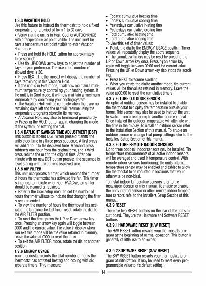
Pressing this button will write default values of alltemperature programs and setup menus into the unit’snonvolatile memory. Take care not to unintentionallypress this button when the thermostat has beenremoved from the wall plate!4.4. PROGRAMMINGYou can change the preset time/and temperatures to suityour schedule for each day of the week. Each day hasfour consecutive periods. They are Morning, Day,Evening, and Night. Separate set points are provided forHeat and Cool.Fan programming is similar to temperature program-ming. It has four consecutive periods, which are inde-pendent of the four temperature periods. The default set-ting for your systems fan requires it to run only asrequired by your environmental system. It may be pro-grammed to maintain a minimum run time on an hourlybasis, or run continuously.4.4.1 WEEKDAY TEMPERATURE PROGRAMMING● Rotate the dial to Set Weekday Programs. The heatand cool set points will be displayed on the left side ofthe display. The start time for the displayed day will flashto show that this is the setting currently ready for edit.● Use the up or down arrow keys to change the starttime for this period. One period ends at the start time ofthe next period. The beginning of that period may not beany closer to the beginning of the next period than one15 minute increment.● Press NEXT to accept the displayed start time andadvance to edit the heat set point. It will be flashing.● Use the up or down arrow keys to change Heat Set tothe temperature you desire.● Press NEXT to accept the displayed heat set point tothe temperature and advance to edit the cool set point. Itwill be flashing.● There is a minimum value that must be maintainedbetween the heat temperature set point and Cool temper-ature set point. The value that must be maintained iscalled the Deadband. It is programmable and may bechanged in the Installer Setup menu. If you move theheat set point temperature to close to the cool set pointtemperature the cool set point temperature will moveaway from the heat set point temperature to maintain thedead band. Conversely the heat set point temperature willmove if you adjust the cool set point temperature toclose. There are programmable limits for both heat andcool, which you will not be able to exceed. These valuesare accessible from the User Setup Menu.● When you have changed the Cool set point to yourdesired temperature, press NEXT to advance to the next period. Its start time will be flashing indicating that it isunder edit.● When all the periods for a day have been set, the starttime for the next weekday will be displayed to begin edit-
ing the settings for that day.● Rotate the dial back to RUN to and accept all currentvalues and end the programming session.4.4.2 WEEKDAY FAN PROGRAMMINGProgramming fan operation is similar to programmingthe temperature periods and set points. Fan periods areindependent of temperature periods and are designatedP1, P2, P3, P4.● Rotate the dial to Set Weekday Programs, then pressand hold the FAN button for over 2 seconds.● The fan day and period will be displayed in the topcenter and right portion of the screen. The bottom por-tion will show the fan mode and start time for that period.The fan mode for this period will be flashing to indicatethat it may be changed with the UP/DOWN arrow keys.Choices are:
■ Auto: default value; the fan will run only when neces-sary for your HVAC system to maintain temperature con-trol.
■ Program: This mode will insure that during everyhour, the fan will run for the for at least the number ofminutes shown at the top left of the display, beginning atthe displayed time for this period until the beginning ofthe next period. If your heating or cooling requirementfulfills the minimum fan run time, additional fan run timewill not be requested. Activation of the fan when neces-sary is done at twenty minute intervals for one third thehourly run time.
■ On: The On setting will run the fan continuously dur-ing this period.● Set the desired Fan mode for his period. Press NEXTto advance and edit this periods start time.● Use the UP or DOWN arrow keys to change the starttime. A period ends at the start time of the next period.The beginning of a period may not be any closer to thebeginning of the next period than one 15 minute incre-ment.● Press NEXT to advance and set the minimum fan runtime if this period is to use program mode.● Pressing NEXT again will bring you to the next period’smode.● When all the periods for a day have been set, the starttime for the next weekday will be displayed to begin edit-ing the settings for that day.● The sequence of days that you may program pro-gresses the weekdays MON - FRI, and repeats.● Then press and hold the FAN button for over 2 sec-onds to return to Weekday temperature editing or rotatethe dial back to RUN to and accept all current values andend the programming session.4.4.3 WEEKEND PROGRAMMINGWeekend programming is identical to weekday program-ming except rotate the dial to set weekend programs, andthe sequence of days that you may program is SAT, SUNand then repeating this two day sequence.
15
4.3.3 VACATION HOLDUse this feature to instruct the thermostat to hold a fixedtemperature for a period of from 1 to 30 days.● Verify that the unit is in Heat, Cool or AUTOCHANGEwith a temperature set point visible. The unit must behave a temperature set point visible to enter VacationHold mode.● Press and hold the HOLD button for approximatelythree seconds. ● Use the UP/DOWN arrow keys to adjust the number ofdays to your preference. The maximum number ofallowed days is 30.● Press NEXT. The thermostat will display the number ofdays remaining in this Vacation Hold.● If the unit is in Heat mode, it will now maintain a mini-mum temperature by controlling your heating system. Ifthe unit is in Cool mode, it will now maintain a maximumtemperature by controlling your cooling system.● The Vacation Hold will be complete when there are noremaining days left and the unit will resume using thetemperature programs stored in its memory.● A Vacation Hold may also be terminated prematurelyby Pressing the HOLD button again, changing the modeof the system, or rotating the dial.4.3.4 DAYLIGHT SAVINGS TIME ADJUSTMENT (DST)This button is labeled DST. When pressed it shifts theunits clock time in a three press sequence. A first presswill add 1 hour to the displayed time. A second presssubtracts one hour from the original time, and a thirdpress returns the unit to the original time. After oneminute with no new DST button presses, the sequence isreset staring with the current displayed time.4.3.5 AIR FILTERThis unit incorporates a timer, which records the numberof hours the thermostat has activated the fan. This timeris intended to indicate when your HVAC systems filtershould be cleaned or replaced.● Refer to the User setup menu to set the number ofhours the timer will use to indicate that changing the filteris recommended.● To view the number of hours the thermostat has acti-vated the fan since the last timer reset, rotate the dial tothe AIR FILTER position.● To reset the timer press the UP or Down arrow keyonce. Pressing an arrow key again will toggle between0000 and the current value. The value in display whenyou exit this mode will be the value retained in memory.Leave the value at 0000 to reset the timer.● To exit the AIR FILTER mode, rotate the dial to anotherposition.4.3.6 ENERGY USAGEYour thermostat records the total number of hours thethermostat has activated heating and cooling with sixseparate timers. They measure:
● Today’s cumulative heating time ● Today’s cumulative cooling time ● Yesterdays cumulative heating time ● Yesterdays cumulative cooling time ● Total cumulative heating time ● Total cumulative cooling time To view this set of timer values:● Rotate the dial to the ENERGY USAGE position. Timervalues will repeatedly display the above sequence.● The cumulative timers may be reset by pressing theUP or Down arrow key once. Pressing an arrow keyagain will toggle between 00:00 and the current value.Pressing the UP or Down arrow key also stops the scroll-ing.● Press NEXT to resume scrolling.● When you rotate the dial to another mode, the currentvalues will be the values retained in memory. Leave thevalue at 00:00 to reset the cumulative timers.4.3.7 FUTURE OUTDOOR SENSORAn optional outdoor sensor may be installed to enablethe thermostat to display the temperature outside yourhome. This sensor may also be used to instruct the unitto switch from a heat pump to another source of heat.Once installed the outdoor temperature will alternate withthe time in the display. To install an outdoor sensor referto the Installation Section of this manual. To enable anoutdoor sensor or change heat pump settings refer to theInstallers Setup Section of this manual.4.3.8 FUTURE REMOTE INDOOR SENSORSUp to three optional indoor sensors may be installed. Thetemperature measurements of all active indoor sensorswill be averaged and used in temperature control. Withremote indoor sensors functioning, the units’ internaltemperature sensor may be enabled or disabled to allowthe thermostat to be mounted in locations that wouldotherwise be non-ideal.To install indoor temperature sensors refer to theInstallation Section of this manual. To enable or disablethe units internal sensor or other remote indoor tempera-ture sensors refer to the Installers Setup Section of thismanual.4.3.9 RESETThere are two RESET buttons on the rear of the unit’s cir-cuit board. They are the Hardware and Software RESETbuttons.4.3.9.1 HARDWARE RESET (H/W RESET)The H/W RESET button restarts your thermostats pro-gram at the beginning of normal operation. This button isgenerally of little use to an owner.
4.3.9.2 SOFTWARE RESET (S/W RESET)The S/W RESET button restarts your thermostats pro-gram at initialization. It may be used to reset every pro-grammable value to it’s default setting.
14
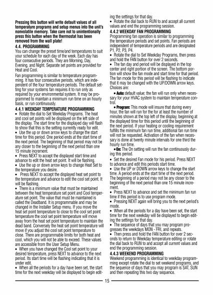
1. FEATURES . . . . . . . . . . . . . . . . . . . . . . . . . . . . . . . . . . . . . . . . . . . . . 22. COMPATIBILITY . . . . . . . . . . . . . . . . . . . . . . . . . . . . . . . . . . . . . . . . 22.1. HEAT STAGES . . . . . . . . . . . . . . . . . . . . . . . . . . . . . . . . . . . . . . . . . . . . 22.2. COOLING/COMPRESSOR STAGES . . . . . . . . . . . . . . . . . . . . . . . . . . 22.3. ELECTRICAL RATINGS . . . . . . . . . . . . . . . . . . . . . . . . . . . . . . . . . . . . 23. INSTALLATION . . . . . . . . . . . . . . . . . . . . . . . . . . . . . . . . . . . . . . . . . 23.1. TOOLS REQUIRED . . . . . . . . . . . . . . . . . . . . . . . . . . . . . . . . . . . . . . . . 23.2. LOCATION . . . . . . . . . . . . . . . . . . . . . . . . . . . . . . . . . . . . . . . . . . . . . . . 33.3. REMOVAL OF OLD UNIT . . . . . . . . . . . . . . . . . . . . . . . . . . . . . . . . . . . 33.4. MOUNTING . . . . . . . . . . . . . . . . . . . . . . . . . . . . . . . . . . . . . . . . . . . . . . 33.5. WIRING . . . . . . . . . . . . . . . . . . . . . . . . . . . . . . . . . . . . . . . . . . . . . . . . . 33.5.1 TERMINAL DEFINITIONS . . . . . . . . . . . . . . . . . . . . . . . . . . . . . . . . . . . . 33.5.2 FREEZE PROTECTION. . . . . . . . . . . . . . . . . . . . . . . . . . . . . . . . . . . . . . . 43.5.3 SPECIAL WIRING NOTES . . . . . . . . . . . . . . . . . . . . . . . . . . . . . . . . . . . . 43.5.4 COMMON WIRING OPTIONS . . . . . . . . . . . . . . . . . . . . . . . . . . . . . . . . . 43.5.5 SINGLE STAGE HEATING SYSTEMS LABEL CROSS REFERENCE. . . . . 43.5.6 SINGLE STAGE COOLING SYSTEMS LABEL CROSS REFERENCE . . . . 43.5.7 SINGLE STAGE FURNACE HEATING AND SINGLE STAGE
COOLING SYSTEM LABEL CROSS REFERENCE . . . . . . . . . . . . . . . . . . 43.5.8 TWO STAGE HEAT, SINGLE STAGE COOL HEAT PUMP SYSTEM
LABEL CROSS REFERENCE . . . . . . . . . . . . . . . . . . . . . . . . . . . . . . . . . . 53.5.9 WIRING DIAGRAMS . . . . . . . . . . . . . . . . . . . . . . . . . . . . . . . . . . . . . . . . 53.6. INSTALL BATTERIES . . . . . . . . . . . . . . . . . . . . . . . . . . . . . . . . . . . . . . 93.7. INSTALLER SETUP. . . . . . . . . . . . . . . . . . . . . . . . . . . . . . . . . . . . . . . . 93.7.1 ACCESS AND NAVIGATE INSTALLER SETUP MENU . . . . . . . . . . . . . . . 93.7.2 INSTALLER SETUP MENU WITH
FURNACE SYSTEM TYPE SELECTED: . . . . . . . . . . . . . . . . . . . . . . . . . . 103.7.3 INSTALLER SETUP MENU WITH HEAT
PUMP SYSTEM TYPE SELECTED. . . . . . . . . . . . . . . . . . . . . . . . . . . . . . 103.7.4 COMPLETING YOUR INSTALLATION . . . . . . . . . . . . . . . . . . . . . . . . . . . 114. OPERATION . . . . . . . . . . . . . . . . . . . . . . . . . . . . . . . . . . . . . . . . . . . . 114.1. OPERATING BASICS . . . . . . . . . . . . . . . . . . . . . . . . . . . . . . . . . . . . . . 114.1.1 UP/DOWN ARROW CHANGE KEYS . . . . . . . . . . . . . . . . . . . . . . . . . . . . 114.1.2 SET DAY AND TIME . . . . . . . . . . . . . . . . . . . . . . . . . . . . . . . . . . . . . . . . 114.1.3 DEFAULT PROGRAM . . . . . . . . . . . . . . . . . . . . . . . . . . . . . . . . . . . . . . . 11
4.1.4 MODES . . . . . . . . . . . . . . . . . . . . . . . . . . . . . . . . . . . . . . . . . . . . . . . . . . 114.1.5 DISPLAY ILLUMINATION . . . . . . . . . . . . . . . . . . . . . . . . . . . . . . . . . . . . 124.2. USER SETUP MENU . . . . . . . . . . . . . . . . . . . . . . . . . . . . . . . . . . . . . . 124.2.1 ACCESS AND NAVIGATE USER SETUP MENU. . . . . . . . . . . . . . . . . . . . 124.2.2 KEYBOARD LOCK . . . . . . . . . . . . . . . . . . . . . . . . . . . . . . . . . . . . . . . . . . 124.2.3 BEEP . . . . . . . . . . . . . . . . . . . . . . . . . . . . . . . . . . . . . . . . . . . . . . . . . . . . 124.2.4 TEMPERATURE DISPLAY FORMAT (F/C DISPLAY) . . . . . . . . . . . . . . . . 134.2.5 CLOCK FORMAT . . . . . . . . . . . . . . . . . . . . . . . . . . . . . . . . . . . . . . . . . . . 134.2.6 CALIBRATION OFFSET . . . . . . . . . . . . . . . . . . . . . . . . . . . . . . . . . . . . . . 134.2.7 MAXIMUM HEAT SETTING. . . . . . . . . . . . . . . . . . . . . . . . . . . . . . . . . . . 134.2.8 MINIMUM COOL SETTING . . . . . . . . . . . . . . . . . . . . . . . . . . . . . . . . . . . 134.2.9 SMART RECOVERY . . . . . . . . . . . . . . . . . . . . . . . . . . . . . . . . . . . . . . . . 134.2.10 FILTER LIMIT . . . . . . . . . . . . . . . . . . . . . . . . . . . . . . . . . . . . . . . . . . . . . 134.2.11 USER SETUP MENU: . . . . . . . . . . . . . . . . . . . . . . . . . . . . . . . . . . . . . . . 134.3. ADVANCED FEATURES AND OPERATION . . . . . . . . . . . . . . . . . . . . 134.3.1 EMERGENCY HEAT. . . . . . . . . . . . . . . . . . . . . . . . . . . . . . . . . . . . . . . . . 134.3.2 FAN MODES . . . . . . . . . . . . . . . . . . . . . . . . . . . . . . . . . . . . . . . . . . . . . . 134.3.3 VACATION HOLD. . . . . . . . . . . . . . . . . . . . . . . . . . . . . . . . . . . . . . . . . . . 144.3.4 DAYLIGHT SAVINGS TIME ADJUSTMENT (DST) . . . . . . . . . . . . . . . . . 144.3.5 AIR FILTER . . . . . . . . . . . . . . . . . . . . . . . . . . . . . . . . . . . . . . . . . . . . . . . 144.3.6 ENERGY USAGE . . . . . . . . . . . . . . . . . . . . . . . . . . . . . . . . . . . . . . . . . . . 144.3.7 FUTURE OUTDOOR SENSOR . . . . . . . . . . . . . . . . . . . . . . . . . . . . . . . . . 144.3.8 FUTURE REMOTE INDOOR SENSORS. . . . . . . . . . . . . . . . . . . . . . . . . . 144.3.9 RESET . . . . . . . . . . . . . . . . . . . . . . . . . . . . . . . . . . . . . . . . . . . . . . . . . . . 144.4. PROGRAMMING. . . . . . . . . . . . . . . . . . . . . . . . . . . . . . . . . . . . . . . . . . 154.4.1 WEEKDAY TEMPERATURE PROGRAMMING. . . . . . . . . . . . . . . . . . . . . 154.4.2 WEEKDAY FAN PROGRAMMING . . . . . . . . . . . . . . . . . . . . . . . . . . . . . . 154.4.3 WEEKEND PROGRAMMING . . . . . . . . . . . . . . . . . . . . . . . . . . . . . . . . . . 154.4.4 COPY PROGRAMMING. . . . . . . . . . . . . . . . . . . . . . . . . . . . . . . . . . . . . . 165. BATTERIES/MAINTENANCE . . . . . . . . . . . . . . . . . . . . . . . . . . . . 165.1. BATTERY INSTALLATION . . . . . . . . . . . . . . . . . . . . . . . . . . . . . . . . . . 166. TECHNICAL DETAILS . . . . . . . . . . . . . . . . . . . . . . . . . . . . . . . . . . . 166.1. STAGING . . . . . . . . . . . . . . . . . . . . . . . . . . . . . . . . . . . . . . . . . . . . . . . . 167. TECHNICAL ASSISTANCE. . . . . . . . . . . . . . . . . . . . . . . . . . . . . . . 168. WARRANTY . . . . . . . . . . . . . . . . . . . . . . . . . . . . . . . . . . . . . . . . . . . . 16
LUXPRO EVERYTHING’STAT ® PSP722EINSTALLATION AND OPERATING INSTRUCTIONS
Mt. Laurel, New Jersey 08054, USA l www.luxproproducts.com
PSP722E
WARNING: Use Energizer® or DURACELL® Alkaline Batteries Only.Energizer® is a registered trademark of Eveready Battery Company, Inc.
DURACELL® is a registered trademark of The Gillette Company, Inc.
4.4.4 COPY PROGRAMMINGThe COPY button allows you to easily copy temperatureor fan programs from any day, to any other day, to allweekdays, to both weekend days, or all days. The Copyfunction copies only the temperature or fan programfrom a day, not both at the same time. To copy a day’stemperature or fan programs from one day to others:● In the appropriate programming mode press COPY.The display will show COPY FROM with current daybeing programmed flashing below.● Use the UP or DOWN arrow buttons to select the dayyou want to copy from. Selections are:
Any single day, SUN - SATAll weekdays MON to FRIBoth weekend days SAT and SUNAll days at once SUN – SAT
● Press NEXT.● Again use the UP or DOWN arrow buttons to select theday or days you want to copy.● Press NEXT to accept the displayed copy to days, andthe copy will be complete.5. BATTERIES/MAINTENANCEDepending on your installation, your unit may requirebatteries to control your HVAC system. If required,replace your thermostat’s batteries at least once a year orwhen the battery symbol appears in the display.5.1. BATTERY INSTALLATION1. Remove fresh batteries from their carton.2. Remove body of thermostat as described duringinstallation.3. Remove the used batteries if present and replace themwithin 90 seconds to avoid having to reset the day andtime.4. Install two new “AA” size Energizer or Duracell alkalinebatteries in the battery compartment. Observe the polari-ty marking shown in the compartment.
WARNING: Use Energizer® or DURACELL®
Alkaline Batteries Only.5. Place the thermostat body back on the wall.NOTE: Replace your thermostat’s batteries with new alkalinebatteries at least once a year or when the battery symbolappears in the display.The use of high quality alkaline batteries is absolutelyrequired for your thermostat to operate properly.
6. TECHNICAL DETAILS6.1. STAGING● Stage one of a heating system will be activated at thevalue of swing 1 below the temperature set point. Stageone of a cooling system will be activated at the value ofswing 1 above the temperature set point.● Stage one of a heating system will be deactivated atthe value of swing 1 above the temperature set point.
Stage one of a cooling system will be deactivated at thevalue of swing 1 below the temperature set point.● Stage two of a heating system will be activated at thevalue of (swing 1 + swing 2) below the temperature setpoint. The auxiliary heat indicator AUX HT will be visiblewhen a second stage of heat is activated. Stage two ofcooling will be activated at the value of (swing 1 + swing2) above the temperature set point.● Stage two of a heating or cooling system will be deac-tivated at the temperature set point.● Stage three of a heating system will be activated at thevalue of (swing 1 + 2*swing 2) below the temperatureset point. ● Stage three of a heating or cooling system will bedeactivated at the temperature set point.7. TECHNICAL ASSISTANCEIf you have any problems installing or using this thermo-stat, please carefully and thoroughly review the instruc-tion manual. If you require assistance, please contact ourTechnical Assistance Department at 856-234-8803 duringregular business hours between 8:00AM and 4:30PMEastern Standard Time, Monday through Friday. You canalso receive technical assistance online anytime day ornight at http://www.luxproproducts.com. Our web siteoffers you answers to the most common technical ques-tions, and also permits you to email your questions toour technical support staff at your convenience.8. WARRANTYLimited Warranty: If this unit fails because of defects inmaterials or workmanship within three years of date oforiginal purchase, LUX Products Corporation will, at itsoption, repair or replace it. This warranty does not coverdamage by accident, misuse, or failure to follow installa-tion instructions. Implied warranties are limited in dura-tion to three years from date of original purchase. Somestates do not allow limitations on how long an impliedwarranty lasts, so the above limitation may not apply toyou. Please return malfunctioning or defective units tothe participating retailer from which purchase was made,along with proof of purchase. Please refer to "TECHNICALASSISTANCE" before returning thermostat. Purchaserassumes all risks and liability for incidental and conse-quential damage resulting from installation and use ofthis unit. Some states do not allow the exclusion of inci-dental or consequential damages, so the above exclusionmay not apply to you. This warranty gives you specificlegal rights and you may also have other rights whichvary from state to state. Applicable in the U.S.A. only.
16
52026
Related Documents