1 1 ME 425 - Psychrometrics & Coil Load Calculation ME 425 Psychrometrics & Coil Load Keith E. Elder, P.E. Coils Coils are the main devices for transferring energy to/from the airstream in an air- handling system. Heat Transfer Media Hydronic Fluid (Water) Steam Direct Expansion Important Coil Load Concepts Apparatus Dew Point Bypass Factor

425-8-Coil Load 2006
Nov 28, 2015
COIL
Welcome message from author
This document is posted to help you gain knowledge. Please leave a comment to let me know what you think about it! Share it to your friends and learn new things together.
Transcript

1
1ME 425 - Psychrometrics & Coil Load Calculation
ME 425
Psychrometrics & Coil Load
Keith E. Elder, P.E.
CoilsCoils are the main devices for transferring energy to/from the airstream in an air-handling system.Heat Transfer Media
Hydronic Fluid (Water)SteamDirect Expansion
Important Coil Load ConceptsApparatus Dew PointBypass Factor

2
2ME 425 - Psychrometrics & Coil Load Calculation
The Psychrometric Chart
Dry Bulb Temperature

3
3ME 425 - Psychrometrics & Coil Load Calculation
SHR
SHR
The ratio of space sensible cooling to total cooling is useful for plotting the slope of the path that supply air travels after introduction into the space.
Sensible Heat Ratio (SHR)
Apparatus Dew Point
Apparatus dew point (ADP) is the coil surface dew point temperature required to accomplish a cooling/dehumidifying process.
Coil Entering AirApparatus
Dew Point
Dry Bulb Temperature
Coil Leaving Air

4
4ME 425 - Psychrometrics & Coil Load Calculation
Apparatus Dew Point
Relationship of ADP to Supply Air and Chilled Water temperatures
Chilled water
Supply Airtewb
tlw
tlew
Metal Surface Temp.
Surface Area
Temp
ADPtlwb
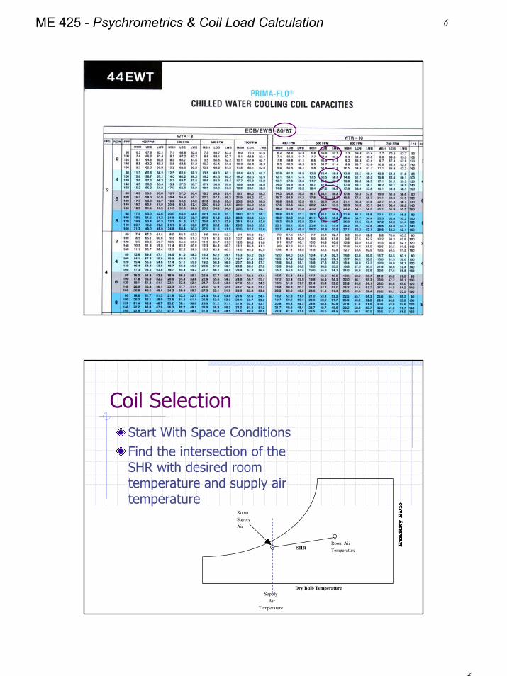
8-Row Coil 80 fpf /2 fps/44 EWT / WTR = 10
Coil Bypass

5
5ME 425 - Psychrometrics & Coil Load Calculation
Apparatus Dew PointAn ADP is essential to any cooling/ dehumidifying process. The chart below shows an impossible process because there is no ADP
Coil
Entering
Air
Dry Bulb Temperature
Coil
Leaving
Air
Bypass FactorSome of the air flowing through the coil impinges on the water tubes or the fins and is cooled to the ADP. Other air passes through unchanged.
The percentage of air that passes through the coil unchanged is called the bypass factor.
Coil Entering Air
Fin
6
6ME 425 - Psychrometrics & Coil Load Calculation
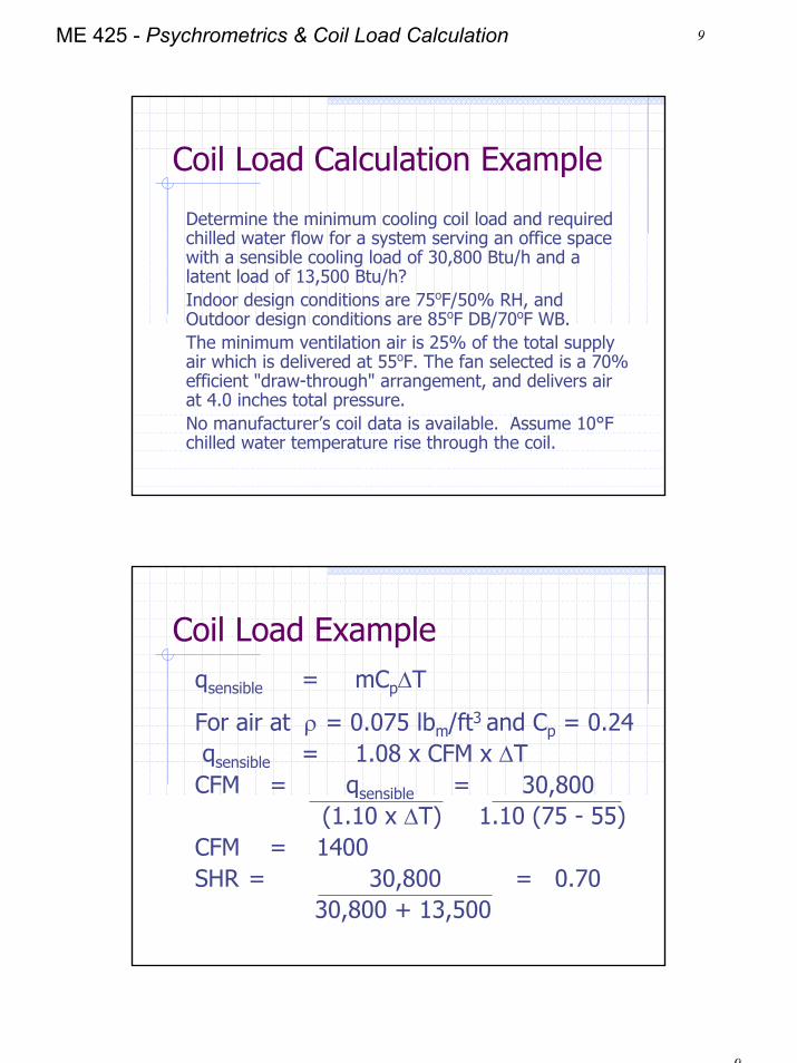
Coil SelectionStart With Space ConditionsFind the intersection of the SHR with desired room temperature and supply air temperature
Room Supply Air
Dry Bulb Temperature
Room Air TemperatureSHR
Supply Air
Temperature

7
7ME 425 - Psychrometrics & Coil Load Calculation
Coil Selection
Determine Outside Air Requirements Using ASHRAE Standard 62
Offices 20 CFM per personSchools 15 CFM per personBars 30 CFM per personSmoking Lounges 60 CFM per personCorridors 0.05 CFM/ft2
Plot Entering/Leaving Conditions
Coil
Entering
AirApparatus
Dew Point
Dry Bulb Temperature
Outside Air
Room Air
Mixed Air
Coil
Leaving
Air

8
8ME 425 - Psychrometrics & Coil Load Calculation
Define Process in Complete Cycle
Coil
Entering
AirApparatus
Dew Point
Dry Bulb Temperature
Outside Air
Room Air
Mixed Air
Coil
Leaving
Air
SHR
Determine Required Coil Capacity
Coil Capacity RequirementQcoil = 4.5 x CFM x ∆h
Dry Bulb Temperature
Entering Air Enthalpy
Leaving Air Enthalpy
h∆
9
9ME 425 - Psychrometrics & Coil Load Calculation
Coil Load Calculation Example
Determine the minimum cooling coil load and required chilled water flow for a system serving an office space with a sensible cooling load of 30,800 Btu/h and a latent load of 13,500 Btu/h? Indoor design conditions are 75oF/50% RH, and Outdoor design conditions are 85oF DB/70oF WB. The minimum ventilation air is 25% of the total supply air which is delivered at 55oF. The fan selected is a 70% efficient "draw-through" arrangement, and delivers air at 4.0 inches total pressure.No manufacturer’s coil data is available. Assume 10°F chilled water temperature rise through the coil.
Coil Load Exampleqsensible = mCp∆T
For air at ρ = 0.075 lbm/ft3 and Cp = 0.24qsensible = 1.08 x CFM x ∆TCFM = qsensible = 30,800
(1.10 x ∆T) 1.10 (75 - 55)CFM = 1400SHR = 30,800 = 0.70
30,800 + 13,500

10
10ME 425 - Psychrometrics & Coil Load Calculation
Coil Load Example
Plot Space Conditions of 75°F/50% RHFind the intersection of the SHR line with space temperature and supply air temperature
55°F
Dry Bulb Temperature
Room Air 75°F / 50% RHSHR=0.70
Supply Air
Temperature
Coil Load Example
Plot Outdoor Conditions of 85°F/ 70°F WBLocate Mixed Air Condition (25% OA)Account for Fan ∆t
55°F
Dry Bulb Temperature
Room Air Design75°F / 50% RHSHR=0.70
Supply Air
Temperature
Outside Air85°F / 70°F WB
53°F
∆tfan
Mixed Air

11
11ME 425 - Psychrometrics & Coil Load Calculation
Coil Load Example
Determine enthalpy for coil entering and leaving conditions
Dry Bulb Temperature
Room Air Design75°F / 50% RHSHR=0.70
Outside Air85°F / 70°F WB
Mixed Air
hLA = 20..5 Btu/lb
hEA = 29.8 Btu/lb
Coil Load Example
qcoil = 4.5 x CFM x ∆h= 4.5 x 1400 x (29.8 - 20.5)= 58,590 Btu/hr
Dry Bulb Temperature
Room Air Design75°F / 50% RHSHR=0.70
Outside Air85°F / 70°F WB
Mixed Air
hLA = 20..5 Btu/lb
hEA = 29.8 Btu/lb

12
12ME 425 - Psychrometrics & Coil Load Calculation
Btu/lbw
Determine Chilled Water Flowqtotal = mCp∆T
For water at ρ = 62.34 lbm/ft3 and Cp = 1.0
qtotal = 500 x GPM x ∆T
GPM = qcoil = 58,590(500 x ∆T) (500 x 10°F)
= 11.7 GPM

13
13ME 425 - Psychrometrics & Coil Load Calculation
Unitary Equipment
HomeworkRead 05F6.14-6.21What is the coil load for the following?
Indoor 76 oF/45% RH - Outdoor 82/66oF Load (Btu/h) 100,000 Sensible - 40,000 LatentSupply air 55oF through draw-through fanFan Total Pressure = 3 in w.c.Fan Efficiency = 60%Outside air = 50% of total supply
Be able to work this problem not necessary to turn in
Related Documents