BC MoTI SUPPLEMENT TO TAC GEOMETRIC DESIGN GUIDE MoTI Section 400 TAC Section Not Applicable April, 2019 Page 400-i 400 CROSS SECTIONS CHAPTER 410 CROSS SECTIONS ........................................................................................................... 410‐1 430 CROSS SECTION ELEMENTS ........................................................................................... 430‐1 440 TYPICAL RURAL SECTIONS FOR BC ................................................................................. 440‐1 450 TYPICAL URBAN SECTIONS FOR BC ................................................................................ 450‐1 400 CROSS SECTION CHAPTER TABLES 430.A Cross Section Elements ..................................................................................................... 430‐1 430.B Design Widths for Shoulder Bikeways .............................................................................. 430‐1 400 CROSS SECTION CHAPTER FIGURES 440.A Typical Section – Rural Local Undivided ........................................................................... 440‐1 440.B Typical Section – Rural Collector and Arterial .................................................................. 440‐2 440.C Typical Section – Rural Freeway/Expressway ‐ No Development to 6 Lanes ................... 440‐3 440.D Typical Section – Rural Freeway/Expressway ‐ With Development to 6 Lanes ................ 440‐4 440.E Alternate Shoulder Detail – Pavement Depth Reduction ................................................. 440‐5 440.F Shoulder Detail with Roadside Barrier or Drainage Curb ................................................. 440‐6 440.G Typical Wall Sections ........................................................................................................ 440‐7 440.H Solid Rock Cut Sections ..................................................................................................... 440‐8 440.I Disposal of Waste Excavation .......................................................................................... 440‐9 450.A Typical Urban Fill Section.................................................................................................. 450‐1 450.B Typical Urban Cut Section................................................................................................. 450‐2

Welcome message from author
This document is posted to help you gain knowledge. Please leave a comment to let me know what you think about it! Share it to your friends and learn new things together.
Transcript

BC MoTI SUPPLEMENT TO TAC GEOMETRIC DESIGN GUIDE MoTI Section 400 TAC Section Not Applicable
April, 2019 Page 400-i
400 CROSS SECTIONS CHAPTER
410 CROSS SECTIONS ........................................................................................................... 410‐1
430 CROSS SECTION ELEMENTS ........................................................................................... 430‐1
440 TYPICAL RURAL SECTIONS FOR BC ................................................................................. 440‐1
450 TYPICAL URBAN SECTIONS FOR BC ................................................................................ 450‐1
400 CROSS SECTION CHAPTER TABLES
430.A Cross Section Elements ..................................................................................................... 430‐1
430.B Design Widths for Shoulder Bikeways .............................................................................. 430‐1
400 CROSS SECTION CHAPTER FIGURES
440.A Typical Section – Rural Local Undivided ........................................................................... 440‐1
440.B Typical Section – Rural Collector and Arterial .................................................................. 440‐2
440.C Typical Section – Rural Freeway/Expressway ‐ No Development to 6 Lanes ................... 440‐3
440.D Typical Section – Rural Freeway/Expressway ‐ With Development to 6 Lanes ................ 440‐4
440.E Alternate Shoulder Detail – Pavement Depth Reduction ................................................. 440‐5
440.F Shoulder Detail with Roadside Barrier or Drainage Curb ................................................. 440‐6
440.G Typical Wall Sections ........................................................................................................ 440‐7
440.H Solid Rock Cut Sections ..................................................................................................... 440‐8
440.I Disposal of Waste Excavation .......................................................................................... 440‐9
450.A Typical Urban Fill Section .................................................................................................. 450‐1
450.B Typical Urban Cut Section ................................................................................................. 450‐2

SUPPLEMENT TO TAC GEOMETRIC DESIGN GUIDE BC MoTI MoTI Section 400 TAC Section Not Applicable
Page 400-ii April, 2019
This page is intentionally left blank
BC MoTI SUPPLEMENT TO TAC GEOMETRIC DESIGN GUIDE MoTI Section 410 TAC Section Not Applicable
April, 2019 Page 410-1
410 CROSS SECTIONS
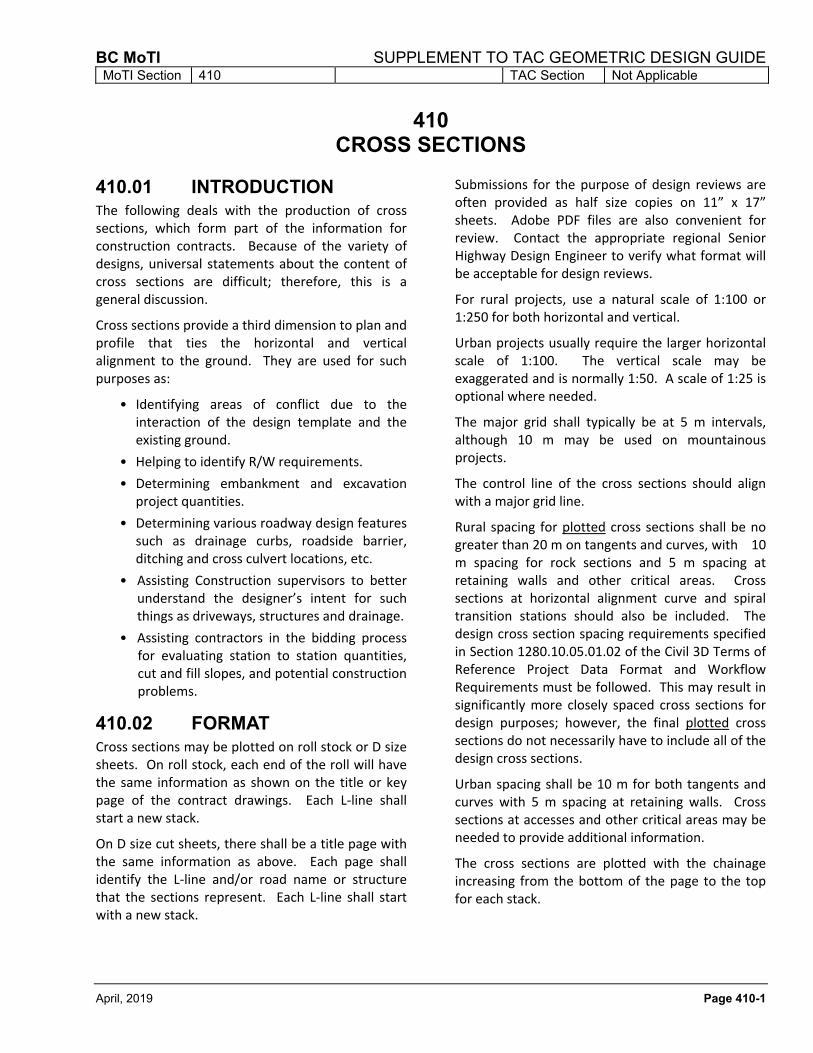
410.01 INTRODUCTION The following deals with the production of cross sections, which form part of the information for construction contracts. Because of the variety of designs, universal statements about the content of cross sections are difficult; therefore, this is a general discussion.
Cross sections provide a third dimension to plan and profile that ties the horizontal and vertical alignment to the ground. They are used for such purposes as:
• Identifying areas of conflict due to the interaction of the design template and the existing ground.
• Helping to identify R/W requirements.
• Determining embankment and excavation project quantities.
• Determining various roadway design features such as drainage curbs, roadside barrier, ditching and cross culvert locations, etc.
• Assisting Construction supervisors to better understand the designer’s intent for such things as driveways, structures and drainage.
• Assisting contractors in the bidding process for evaluating station to station quantities, cut and fill slopes, and potential construction problems.
410.02 FORMAT Cross sections may be plotted on roll stock or D size sheets. On roll stock, each end of the roll will have the same information as shown on the title or key page of the contract drawings. Each L‐line shall start a new stack.
On D size cut sheets, there shall be a title page with the same information as above. Each page shall identify the L‐line and/or road name or structure that the sections represent. Each L‐line shall start with a new stack.
Submissions for the purpose of design reviews are often provided as half size copies on 11” x 17” sheets. Adobe PDF files are also convenient for review. Contact the appropriate regional Senior Highway Design Engineer to verify what format will be acceptable for design reviews.
For rural projects, use a natural scale of 1:100 or 1:250 for both horizontal and vertical.
Urban projects usually require the larger horizontal scale of 1:100. The vertical scale may be exaggerated and is normally 1:50. A scale of 1:25 is optional where needed.
The major grid shall typically be at 5 m intervals, although 10 m may be used on mountainous projects.
The control line of the cross sections should align with a major grid line.
Rural spacing for plotted cross sections shall be no greater than 20 m on tangents and curves, with 10 m spacing for rock sections and 5 m spacing at retaining walls and other critical areas. Cross sections at horizontal alignment curve and spiral transition stations should also be included. The design cross section spacing requirements specified in Section 1280.10.05.01.02 of the Civil 3D Terms of Reference Project Data Format and Workflow Requirements must be followed. This may result in significantly more closely spaced cross sections for design purposes; however, the final plotted cross sections do not necessarily have to include all of the design cross sections.
Urban spacing shall be 10 m for both tangents and curves with 5 m spacing at retaining walls. Cross sections at accesses and other critical areas may be needed to provide additional information.
The cross sections are plotted with the chainage increasing from the bottom of the page to the top for each stack.
SUPPLEMENT TO TAC GEOMETRIC DESIGN GUIDE BC MoTI MoTI Section 410 TAC Section Not Applicable
Page 410-2 April, 2019
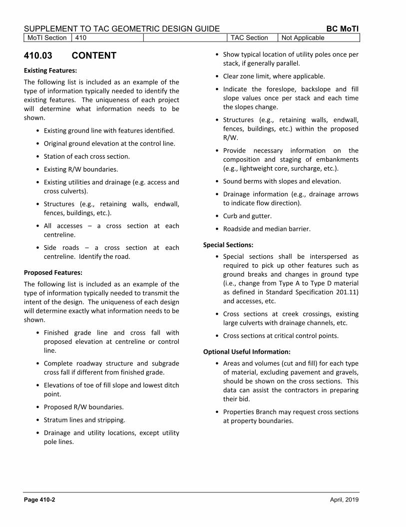
410.03 CONTENT
Existing Features:
The following list is included as an example of the type of information typically needed to identify the existing features. The uniqueness of each project will determine what information needs to be shown.
• Existing ground line with features identified.
• Original ground elevation at the control line.
• Station of each cross section.
• Existing R/W boundaries.
• Existing utilities and drainage (e.g. access and cross culverts).
• Structures (e.g., retaining walls, endwall, fences, buildings, etc.).
• All accesses – a cross section at each centreline.
• Side roads – a cross section at each centreline. Identify the road.
Proposed Features:
The following list is included as an example of the type of information typically needed to transmit the intent of the design. The uniqueness of each design will determine exactly what information needs to be shown.
• Finished grade line and cross fall with proposed elevation at centreline or control line.
• Complete roadway structure and subgrade cross fall if different from finished grade.
• Elevations of toe of fill slope and lowest ditch point.
• Proposed R/W boundaries.
• Stratum lines and stripping.
• Drainage and utility locations, except utility pole lines.
• Show typical location of utility poles once per stack, if generally parallel.
• Clear zone limit, where applicable.
• Indicate the foreslope, backslope and fill slope values once per stack and each time the slopes change.
• Structures (e.g., retaining walls, endwall, fences, buildings, etc.) within the proposed R/W.
• Provide necessary information on the composition and staging of embankments (e.g., lightweight core, surcharge, etc.).
• Sound berms with slopes and elevation.
• Drainage information (e.g., drainage arrows to indicate flow direction).
• Curb and gutter.
• Roadside and median barrier.
Special Sections:
• Special sections shall be interspersed as required to pick up other features such as ground breaks and changes in ground type (i.e., change from Type A to Type D material as defined in Standard Specification 201.11) and accesses, etc.
• Cross sections at creek crossings, existing large culverts with drainage channels, etc.
• Cross sections at critical control points.
Optional Useful Information:
• Areas and volumes (cut and fill) for each type of material, excluding pavement and gravels, should be shown on the cross sections. This data can assist the contractors in preparing their bid.
• Properties Branch may request cross sections at property boundaries.

BC MoTI SUPPLEMENT TO TAC GEOMETRIC DESIGN GUIDE MoTI Section 430 TAC Section 4 and 5.3.2.5
April, 2019 Page 430-1
430 CROSS SECTION ELEMENTS
Table 430.A summarizes the cross section elements for BC highways according to Design Speed, Classification and Design Volumes. (Also refer to Figures 440.A through 440.H). See Section 620 for Clear Zone discussion.
Table 430.A Cross Section Elements
Road Class
Total Design Volume
Lane Width (m)
Paved Shoulder
Width 1
(m)
Design
Speed 2
(km/h)
Normal X‐Fall
Fill Slope
(desirable)
LVR 3 ≤ 200 ADT Refer to
Section
510 3
0.5 Gravel 30‐90 Refer to Section
510 3
2 to 1
RLU 3.6 1.0 4 50‐80 4 to 1
≤ 450 DHV 5 1.5 50‐80
RCU 3.6 4 to 1 > 450 DHV
5 1.5 60‐90
RCD 3.6 2.5 60‐90 4 or 5 to 1
< 200 DHV 5 3.6 1.5 70‐90 0.02 m/m
RAU ≤ 450 DHV 5 3.6 2.0 70‐90 4 or 5 to 1
> 450 DHV 5 3.6 2.5 80‐100
RAD 3.7 3.0 80‐100 4 or 5 to 1
RED 3.7 3.0 80‐120 4 or 5 to 1
RFD 3.7 3.0 80‐120 4 or 5 to 1
1 Minimum width is 1.5 m for Shoulder Bikeway when applicable. See Table 430.B below.
2 Justification is required where less than the maximum design speed for each classification is selected, except for RED and RFD where justification is required for a design speed less than 110 km/h.
3 See Section 510 for Low‐volume Roads details.
4 Typical minimum shoulder width required to nearest edge of roadside barrier is 1.3 m.
5 On a typical rural highway, the DHV is about 15% of the ADT.
Table 430.B Design Widths for Shoulder Bikeways
Controlling Condition Minimum Design Width (m)
For Most Cases, except as below 1.5
For Design Speed ≥ 70 km/h and SADT > 5,000 2.0
For Design Speed > 80 km/h and SADT > 10,000 2.5
All Freeways and Expressways 3.0
The travel lane(s) next to a shoulder bikeway should be at least 3.6 m wide
SADT = Summer Average Daily Traffic (July and August).

SUPPLEMENT TO TAC GEOMETRIC DESIGN GUIDE BC MoTI MoTI Section 430 TAC Section 4 and 5.3.2.5
Page 430-2 April, 2019
This page is intentionally left blank.

Sh
ou
ld
erin
g
1.0
V
aria
ble
d
ep
th
A
P (N
ote
7
)
3.6
L
an
e
1
.
5
:
1
30
0 m
m m
in
.
Po
in
t
Ou
tsid
e D
itch
B
a
c
k
s
l
o
p
e
3
:
1
3.0
m
in
.
1.0
W1
.0
T
yp
ica
lly 1
50
m
m o
f 2
5 m
m C
BC
T
yp
ica
lly 1
50
m
m o
f e
ith
er 7
5 m
m, 5
0 m
m o
r 2
5 m
m C
BC
3.6
L
an
e
L.E.
L.E.
20:1
1.0
4
:
1
P.E.
P.E.
EA
RT
H C
UT
S
EC
TIO
N
Note 4
If p
ossib
le
, p
la
ce
p
ole
s o
n cu
t b
ackslo
pe
.
In
fill, m
axim
ize
o
ffse
t fo
r sa
fe
ty.
-0.02 m
/m
in T
angent
Note 1
N
o
t
e
8
Parallel to F
inished G
rade (N
ote 2)
W
Gra
ve
l
Sh
ou
ld
er
Note 4
Note 1
(R
efe
r to
P
ave
me
nt S
tru
ctu
re
D
esig
n G
uid
elin
es T
-0
1/1
5)
Bre
ak
Po
in
t
}
4
:1
SG
SB
3
00
m
m M
in
im
um
in
S
oil (S
et a
t ℄)
SG
SB
1
50
m
m M
in
im
um
in
R
ock (S
et a
t ℄)
℄1
.0
Cle
ar Z
on
e W
id
th
M
a
x
.
1
.
5
:
1
O
p
tio
n
a
l
No
te
9
Min
.
3.0
be
yo
nd
to
e
No
te
1
0
Ag
gre
ga
te
≥ C
le
ar Z
on
e W
id
th
N
o
t
e
1
1
Wh
ere
m
ate
ria
l is a
pp
ro
pria
te
,
20
:1
d
itch
slo
pe
is e
xte
nd
ed
to
a
cco
mp
lish
sid
e b
orro
w
wh
en
re
qu
ire
d
(N
ote
5
)
No
te
10
(c)
No
te
1
0(b
)
EA
RT
H F
ILL S
EC
TIO
N
No
te
1
1
Gra
ve
l S
ho
uld
er
W =
4 x (D
epth of A
P)
Min. W
=
0.5
}
Te
rm
s:
Notes:
1. S
ee T
able 430.A
for lane and shoulder w
idths.
2. T
angent subgrade m
ay be increased to -0.03 or -0.04 m
/m
in earth to facilitate drainage,
but only w
hen directed by G
eotechnical S
taff.
3. F
or rock ditch details, see F
igure 440.H
4. F
or roadside barrier, 1.3 m
is required to the nearest edge of barrier.
5. T
hese are typical gravel depths to be used in the absence of a specific geotechnical recom
mendation.
6. D
esign S
peeds 50 - 80 km
/h.
7. T
ype "B
", 100,000 to 20,000,000 E
SA
Ls, use 75 m
m to 150 m
m of A
P;
or T
ype "C
", <
100,000 E
SA
Ls, use 50 m
m to 75 m
m of A
P.
8. F
ill slopes should be as flat as possible and no steeper than 1.5:1. G
eotechnical recom
mendations m
ay
specify a m
axim
um
slope flatter than 2:1. D
esirable is 4:1 or flatter.
9. R
ounding or "sm
oothing" at B
reak P
oint to be done during construction.
10. C
lear Z
one is a function of S
peed and T
raffic V
olum
e. C
lear Z
one W
idth to be in accordance w
ith the
requirem
ents in S
ection 620. U
tilities should be located outside of the C
lear Z
one. T
he desirable location of
utility poles shall be, in order of preference: (a) m
in. 2 m
beyond top of cut, (b) m
in. 3 m
beyond low
est ditch
point, (c) m
in. 3 m
beyond toe of fill. S
ee the current edition of the M
inistry's U
tility P
olicy M
anual for
additional placem
ent guidelines.
11. T
he 3:1 ditch slope is not m
andatory. A
single backslope m
ay be used starting at the low
point of the ditch.
Achieving clear zone w
idth is desirable, but if the backslope is relatively sm
ooth and obstacle-free, it m
ay not
be a significant hazard, regardless of its distance from
the roadw
ay.
AP
Asp
ha
lt P
ave
me
nt
CB
CC
ru
sh
ed
B
ase
C
ou
rse
SG
SB
Se
le
ct G
ra
nu
la
r S
ub
B
ase
L.E
.L
an
e E
dg
e
P.E
.P
ave
me
nt E
dg
e
ES
AL
Eq
uiva
le
nt S
in
gle
A
xle
L
oa
d
BC MoTI SUPPLEMENT TO TAC GEOMETRIC DESIGN GUIDE
MoTI Section TAC Section Figure 4.13.2440
April, 2019 Page 440-1
Figure 440.A Typical Section - Rural Local Undivided
N.T.S.

Term
s:
Notes:
1. S
ee T
able 430.A
for Lane and S
houlder W
idths.
2. R
ounding or "sm
oothing" at B
reak P
oint to be done during construction.
3. C
lear Z
one is a function of S
peed and T
raffic V
olum
e. C
lear Z
one W
idth to be in accordance w
ith the requirem
ents in S
ection 620. U
tilities
should be located outside of the C
lear Z
one. T
he desirable location of utility poles shall be, in order of preference: (a) m
in. 2 m
beyond top
of cut, (b) m
in. 3 m
beyond low
est ditch point, (c) m
in. 3 m
beyond toe of fill. S
ee the current edition of the M
inistry's U
tility P
olicy M
anual for
additional placem
ent guidelines.
4. M
inim
um
half-w
idth is 1.3 m
from
Lane E
dge to C
entreline. C
heck for S
SD
along m
edian barrier on curves. M
edian barrier m
ay not be
required on 4-Lane C
ollectors or A
rterials w
ith low
volum
es and is not generally used on 2-Lane C
ollectors or A
rterials.
5. T
angent subgrade m
ay be increased to -0.03 or -0.04 m
/m
in earth to facilitate drainage, but only w
hen directed by G
eotechnical S
taff.
6. S
ee F
igure 440.F
through 440.H
for B
arrier/D
rainage C
urb, R
etaining W
all and R
ock D
itch D
etails.
7. T
hese are "typical" gravel depths to be used in the absence of a specific G
eotechnical recom
mendation.
8. T
ype "A
", ≥
20,000,000 E
SA
Ls, use m
in. 150 m
m of A
P; or T
ype "B
", 100,000 to 20,000,000 E
SA
Ls, use 75 m
m to 150 m
m of A
P. W
here
pavem
ent is ≥
100 m
m, full depth extends only 0.6 m
into the paved shoulder, depending on shoulder w
idth. S
ee F
igure 440.E
for this
Alternate S
houlder D
etail.
9. D
itch slopes and fill slopes steeper than 4:1 m
ust be evaluated for barrier need.
Asphalt P
avem
ent
Crushed B
ase C
ourse
Select G
ranular S
ub B
ase
Lane E
dge
Pavem
ent E
dge
Equivalent S
ingle A
xle Load
AP
CB
C
SG
SB
L.E
.
P.E
.
ES
AL
10.
The 3:1 ditch slope is not m
andatory. A
single backslope m
ay be used starting at the low
point of the ditch. A
chieving clear zone w
idth is desirable,
but if the backslope is relatively sm
ooth and obstacle-free, it m
ay not be a significant hazard, regardless of its distance from
the roadw
ay.
L.E.
1
.
5
:
1
-0.02 m
/m
20:1
3
:
1
Ou
tsid
e D
itch
Po
in
t
B
a
c
k
s
l
o
p
e
P.E.
No
te
1
P.E.
Gra
ve
l S
ho
uld
er
4
:1
N
o
te
9
L.E.
L.E.
L.E.
RO
CK
D
IT
CH
DIV
ID
ED
C
OL
LE
CT
OR
O
R A
RT
ER
IA
L
UN
DIV
ID
ED
C
OL
LE
CT
OR
O
R A
RT
ER
IA
L
In
sid
e D
itch
P
oin
t
1.3
1.3
No
te
1
W0
.6
W
1.0
1.0
30
0 m
m m
in
.
Utility S
etb
ack, N
ote
3
(c)
Utility S
etb
ack, N
ote
3
(c)
Sh
ou
ld
er
No
te
1
-0.02 m
/m
Sh
ou
ld
er
La
ne
EA
RT
H C
UT
S
EC
TIO
N
Typ
ica
lly 1
50
m
m o
f e
ith
er 7
5 m
m, 5
0 m
m o
r 2
5 m
m C
BC
Typ
ica
lly 1
50
m
m o
f 2
5 m
m C
BC
Sh
ou
ld
erin
g
Ag
gre
ga
te
Utility S
etb
ack, N
ote
3
(a
),(b
)
*
0.9
P.E.
Sh
ou
ld
er
(R
efe
r to
P
ave
me
nt S
tru
ctu
re
D
esig
n G
uid
elin
es T
-0
1/1
5)
Parallel to F
inished G
rade (N
ote 5)
Parallel to F
inished G
rade (N
ote 5)
Va
ria
ble
d
ep
th
A
P (N
ote
8
)
No
te
1
No
te
4
La
ne
No
te
1
Gra
ve
l
Sh
ou
ld
er
La
ne
No
te
1
La
ne
No
te
1
La
ne
No
te
1
La
ne
No
te
1
Sh
ou
ld
er
No
te
1
Typ
ica
lly 1
50
m
m o
f e
ith
er 7
5 m
m, 5
0 m
m o
r 2
5 m
m C
BC
Typ
ica
lly 1
50
m
m o
f 2
5 m
m C
BC
4
:1
o
r F
la
tte
r
Sh
ou
ld
erin
g
Ag
gre
ga
te
SG
SB
3
00
m
m M
in
im
um
in
S
oil (S
et a
t ℄)
SG
SB
1
50
m
m M
in
im
um
in
R
ock (S
et a
t ℄)
Cle
ar Z
on
e W
id
th
, N
ote
3
1.0
Bre
ak
Po
in
t
Cle
ar Z
on
e W
id
th
, N
ote
3
1.0
1
.
5
:
1
4
:1
o
r F
la
tte
r
30
0 m
m m
in
.
℄
℄
*
Slo
pe
sh
ou
ld
b
e fla
tte
ne
d o
r
ditch
w
id
en
ed
w
he
re
n
ee
de
d
to
e
nsu
re
th
at O
utsid
e D
itch
Po
in
t is ≥
C
le
ar Z
on
e.
No
te
2
Wh
ere
m
ate
ria
l is
ap
pro
pria
te
, 2
0:1
d
itch
slo
pe
is e
xte
nd
ed
to
acco
mp
lish
sid
e b
orro
w
wh
en
re
qu
ire
d.
3.0
To
e o
f F
ill
Min
.
3.0
Min
.
No
te
3
(c)
No
te
3
(b
)
2.0
Min
.
No
te
3
(a
)
O
p
tio
n
a
l
1
.
5
:
1
O
p
tio
n
a
l
Bre
ak
Po
in
t
No
te
2
≥ C
le
ar Z
on
e W
id
th
, N
ote
1
0
}
(R
efe
r to
P
ave
me
nt S
tru
ctu
re
D
esig
n G
uid
elin
es T
-0
1/1
5)
SG
SB
3
00
m
m M
in
im
um
in
S
oil (S
et a
t ℄)
SG
SB
1
50
m
m M
in
im
um
in
R
ock (S
et a
t ℄)}
N
o
te
9
N
o
te
9
N
o
t
e
1
0
Va
ria
ble
d
ep
th
A
P (N
ote
8
)
(N
ote
7
)
(N
ote
7
)
M
a
x
.
M
a
x
.
EA
RT
H F
IL
L S
EC
TIO
N
*
WW
=
4
x (D
ep
th
o
f A
P)
Min
. W
=
0
.5
}
Gra
ve
l S
ho
uld
er
W =
4
x (D
ep
th
o
f A
P)
Min
. W
=
0
.5
}
SUPPLEMENT TO TAC GEOMETRIC DESIGN GUIDE BC MoTI
MoTI Section TAC Section Figures 4.13.4, 6, 8 & 10440
April, 2019Page 440-2
Figure 440.B Typical Section - Rural Collector and Arterial
N.T.S.

4 LA
NE
D
EP
RE
SS
ED
M
ED
IA
N
ME
DIA
N B
AR
RIE
R P
LA
CE
ME
NT
4 LA
NE
N
AR
RO
W M
ED
IA
N
1.3
Pro
file
C
arrie
d o
n F
in
ish
ed
G
ra
de
P
oin
t
Sh
ou
ld
erin
g A
gg
.
L.E.
Ditch
P
oin
t
EA
RT
H C
UT
S
EC
TIO
N
Su
bg
ra
de
H
in
ge
P
oin
t
DIT
CH
G
RA
DE
P
OIN
T -
No
te
4
1.3
L.E.
In
sid
e D
itch
P
oin
t
30
0 m
m m
in
.
Ba
ckslo
pe
Ou
tsid
e
(m
in
. d
ep
th
1
50
m
m)
Sh
ou
ld
erin
g
Asp
ha
lt
1
5
0
m
m
Utility S
etb
ack, N
ote
3
-0.02 m
/m
Sh
ou
ld
er
Pa
ve
d
3.0
3.7
L.E.
P.E.
L.E.
0.7
3.7
2.2
L.E.
1
.
5
:
1
6.5
4.3
-0.02 m
/m
6.5
1
.
5
:
1
4
:1
to
5
:1
Typ
e D
4.3
1.5
2.2
1.3
L.E.
3.7
L.E.
3.7
W
3.0
L.E.
Utility S
etb
ack, N
ote
3
1.0
1.0
20:1
3
:
1
P.E.
Cle
ar Z
on
e W
id
th
Sh
ou
ld
erin
g
Ag
gre
ga
te
Sh
ou
ld
erin
g
Ag
gre
ga
te
Parallel to F
inished G
rade (N
ote 5)
Parallel to F
inished G
rade (N
ote 5)
Ag
gre
ga
te
To
p S
oil
(m
in
. d
ep
th
1
50
m
m)
To
p S
oil
Typ
e D
Typ
ica
lly 1
50
m
m o
f e
ith
er 7
5 m
m, 5
0 m
m o
r 2
5 m
m C
BC
Typ
ica
lly 1
50
m
m o
f 2
5 m
m C
BC
(N
ote
7
)
(R
efe
r to
P
ave
me
nt S
tru
ctu
re
D
esig
n G
uid
elin
es T
-0
1/1
5)
Bre
ak
Po
in
t
1
.
5
:
1
≥ C
le
ar Z
on
e W
id
th
, N
ote
1
0
* S
lo
pe
sh
ou
ld
b
e
fla
tte
ne
d w
he
re
n
ee
de
d to
en
su
re
th
at O
utsid
e D
itch
Po
in
t is ≥ C
le
ar Z
on
e.
N
o
te
9
Wh
ere
m
ate
ria
l is a
pp
ro
pria
te
,
20
:1
d
itch
slo
pe
is e
xte
nd
ed
to
a
cco
mp
lish
sid
e b
orro
w
wh
en
re
qu
ire
d
va
ria
ble
to
a
llo
w fo
r la
te
ra
l a
nd
lo
ng
itu
din
al d
ra
in
ag
e. M
in
im
um
m
ed
ia
n
lo
ng
itu
din
al d
itch
g
ra
de
is 0
.5
%.
SG
SB
3
00
m
m M
in
im
um
in
S
oil (S
et a
t ℄)
SG
SB
1
50
m
m M
in
im
um
in
R
ock (S
et a
t ℄)}
1.0
Sh
ou
ld
er
Pa
ve
d
℄
℄
O
p
tio
n
a
l
No
te
2
No
te
1
No
te
1
4
:1
o
r F
la
tte
rN
o
te
9
N
o
t
e
1
0
Va
ria
ble
d
ep
th
A
P (N
ote
8
)
EA
RT
H F
ILL S
EC
TIO
N
M
a
x
.
4
:1
o
r
F
la
tte
r
*
0.7
W
W =
4
x (D
ep
th
o
f A
P)
Min
. W
=
0
.5
Pro
file
C
arrie
d o
n
Fin
ish
ed
G
ra
de
P
oin
t
Notes:
1. S
houlder W
idths are typically 3.0 m
. E
xceptions perm
itted w
ith sign-off by C
hief E
ngineer.
See F
ig. 440.E
for A
lternate S
houlder D
etail using 50 m
m or 75 m
m of A
P.
2. R
ounding or "sm
oothing" at B
reak P
oint to be done during construction.
3. C
le
ar Z
on
e is a
fu
nctio
n o
f S
pe
ed
a
nd
T
ra
ffic V
olu
me
. C
le
ar Z
on
e W
id
th
to
b
e in
a
cco
rd
an
ce
w
ith
th
e re
qu
ire
me
nts in
S
ectio
n 6
20
.
Utilitie
s sh
ou
ld
b
e lo
ca
te
d o
utsid
e o
f th
e C
le
ar Z
on
e. T
he
d
esira
ble
lo
ca
tio
n o
f u
tility p
ole
s sh
all b
e, in
o
rd
er o
f p
re
fe
re
nce
: (a
) m
in
. 2
m
be
yo
nd
to
p o
f cu
t, (b
) m
in
. 3
m
b
eyo
nd
lo
we
st d
itch
p
oin
t, (c) m
in
. 3
m
b
eyo
nd
to
e o
f fill. S
ee
th
e cu
rre
nt e
ditio
n o
f th
e M
in
istry's U
tility
Po
licy M
an
ua
l fo
r a
dd
itio
na
l p
la
ce
me
nt g
uid
elin
es.
4. M
in
im
um
h
alf-w
id
th
is 1
.3
m
fro
m L
an
e e
dg
e to
C
en
tre
lin
e. C
he
ck fo
r S
SD
a
lo
ng
m
ed
ia
n b
arrie
r o
n cu
rve
s. M
ed
ia
n B
arrie
r m
ay n
ot b
e
re
qu
ire
d o
n E
xp
re
ssw
ays o
r F
re
ew
ays in
itia
lly; a
llo
wa
nce
is m
ad
e fo
r p
la
ce
me
nt a
t la
te
r tim
e. C
en
tre
lin
e ra
diu
s a
nd
/o
r m
ed
ia
n w
id
th
s
fo
r u
ltim
ate
p
la
ce
me
nt o
f b
arrie
r a
re
to
b
e ch
ecke
d fo
r S
SD
.
5. T
an
ge
nt S
ub
gra
de
m
ay b
e in
cre
ase
d to
-0
.0
3 o
r -0
.0
4 m
/m
in
e
arth
to
fa
cilita
te
d
ra
in
ag
e, b
ut o
nly w
he
n d
ire
cte
d b
y G
eo
te
ch
nica
l S
ta
ff.
6. S
ee
F
ig
ure
4
40
.F
th
ro
ug
h 4
40
.H
fo
r B
arrie
r/D
ra
in
ag
e C
urb
, R
eta
in
in
g W
all a
nd
R
ock D
itch
D
eta
ils.
7. T
hese are "typical" gravel depths to be used in the absence of a specific G
eotechnical recom
mendation.
8. T
ype "A
", ≥
20,000,000 E
SA
Ls, use m
in. 150 m
m of A
P; or T
ype "B
", 100,000 to 20,000,000 E
SA
Ls, use 75 m
m to 150 m
m of
AP
. W
here pavem
ent is ≥
100 m
m, full depth extends only 0.6 m
into the paved shoulder, depending on shoulder w
idth.
9. D
itch slopes and fill slopes steeper than 4:1 m
ust be evaluated for barrier need.
Term
s:
Asphalt P
avem
ent
Crushed B
ase C
ourse
Select G
ranular S
ub B
ase
Lane E
dge
Pavem
ent E
dge
Equivalent S
ingle A
xle Load
Earth E
mbankm
ent
material per S
S 201.37
AP
CB
C
SG
SB
L.E
.
P.E
.
ES
AL
Type D
10.
The 3:1 ditch slope is not m
andatory. A
single backslope m
ay be used starting at the low
point of the ditch. A
chieving clear zone w
idth is desirable,
but if the backslope is relatively sm
ooth and obstacle-free, it m
ay not be a significant hazard, regardless of its distance from
the roadw
ay.
BC MoTI SUPPLEMENT TO TAC GEOMETRIC DESIGN GUIDE
MoTI Section TAC Section Figure 4.13.12440
April, 2019 Page 440-3
Figure 440.C Rural Freeway/Expressway - No Development to 6 Lanes
N.T.S.

Pro
file
C
arrie
d o
n ℄
6 LA
NE
D
EV
ELO
PM
EN
T
ME
DIA
N B
AR
RIE
R P
LA
CE
ME
NT
Shouldering A
gg.
L.E.
2.5
3.7
L.E.
2.8
2.5
No
te
4
2.8
L.E.
3.7
L.E.
Ditch
P
oin
t
EA
RT
H C
UT
S
EC
TIO
N
Su
bg
ra
de
H
in
ge
P
oin
t
DIT
CH
G
RA
DE
P
OIN
T -
In
sid
e D
itch
P
oin
t
30
0 m
m m
in
.
Ba
ckslo
pe
Ou
tsid
e
(m
in
. d
ep
th
1
50
m
m)
Utility S
etb
ack, N
ote
3
-0.02 m
/m
Sh
ou
ld
er
Pa
ve
d
3.0
3.7
L.E.
P.E.
L.E.
3.7
2.2
L.E.
1
.
5
:
1
6.5
0.7
4.3
-0.02 m
/m
6.5
1
.
5
:
1
Typ
e D
4.3
1.5
2.2
1.3
L.E.
3.7
L.E.
3.7
W
3.0
L.E.
Utility S
etb
ack, N
ote
3
1.0
1.0
20:1
3
:
1
P.E.
Cle
ar Z
on
e W
id
th
Sh
ou
ld
erin
g
Ag
gre
ga
te
Sh
ou
ld
erin
g
Ag
gre
ga
te
Parallel to F
inished G
rade (N
ote 5)
Parallel to F
inished G
rade (N
ote 5)
To
p S
oil
(m
in
. d
ep
th
1
50
m
m)
To
p S
oil
Typ
e D
Typ
ica
lly 1
50
m
m o
f e
ith
er 7
5 m
m, 5
0 m
m o
r 2
5 m
m C
BC
Typ
ica
lly 1
50
m
m o
f 2
5 m
m C
BC
(N
ote
7
)
(R
efe
r to
P
ave
me
nt S
tru
ctu
re
D
esig
n G
uid
elin
es T
-0
1/1
5)
Bre
ak
Po
in
t
1
.
5
:
1
≥ C
le
ar Z
on
e W
id
th
, N
ote
1
0
* S
id
e slo
pe
sh
ou
ld
b
e
fla
tte
ne
d w
he
re
n
ee
de
d to
en
su
re
th
at O
utsid
e D
itch
Po
in
t is ≥ C
le
ar Z
on
e.
N
o
te
9
Wh
ere
m
ate
ria
l is a
pp
ro
pria
te
,
20
:1
d
itch
slo
pe
is e
xte
nd
ed
to
acco
mp
lish
sid
e b
orro
w w
he
n re
qu
ire
d
va
ria
ble
to
a
llo
w fo
r la
te
ra
l a
nd
lo
ng
itu
din
al d
ra
in
ag
e.
Min
im
um
m
ed
ia
n lo
ng
itu
din
al d
itch
g
ra
de
is 0
.5
%.
SG
SB
3
00
m
m M
in
im
um
in
S
oil (S
et a
t ℄)
SG
SB
1
50
m
m M
in
im
um
in
R
ock (S
et a
t ℄)}
1.0
Sh
ou
ld
er
Pa
ve
d
℄
O
p
tio
n
a
l
No
te
2
No
te
1
No
te
1
℄
Pro
file
C
arrie
d o
n ℄
4
:1
o
r F
la
tte
rN
o
te
9
N
o
t
e
1
0
Va
ria
ble
d
ep
th
A
P (N
ote
8
)
4
:1
o
r
F
la
tte
r
*
M
a
x
.
EA
RT
H F
ILL S
EC
TIO
N
W
W =
4
x (D
ep
th
o
f A
P)
Min
. W
=
0
.5
4
:1
to
5
:1
N
o
s
te
e
p
e
r th
a
n
4
:1
N
o
te
1
1
N
o
te
1
1
SU
PE
RE
LE
VA
TE
D S
EC
TIO
N
1.5
L.E.
0.65
0.5
Profile
Carried on ℄
6.5
℄
Shouldering A
gg.
Concrete
Median B
arrier
S
te
e
p
e
r
th
a
n
4
:1
P.E.
N
o
te
1
1
2.2
L.E.
6.5
4.3
℄
1.5
De
pth
V
arie
s
Term
s:
Asphalt P
avem
ent
Crushed B
ase C
ourse
Select G
ranular S
ub B
ase
Lane E
dge
Pavem
ent E
dge
Equivalent S
ingle A
xle Load
Earth E
mbankm
ent
material per S
S 201.37
AP
CB
C
SG
SB
L.E
.
P.E
.
ES
AL
Type D
Notes:
1. S
houlder W
idths are typically 3.0 m
. E
xceptions perm
itted w
ith sign-off by C
hief E
ngineer.
See F
ig. 440.E
for A
lternate S
houlder D
etail using 50 m
m or 75 m
m of A
P.
2. R
ou
nd
in
g o
r "sm
oo
th
in
g" a
t B
re
ak P
oin
t to
b
e d
on
e d
urin
g co
nstru
ctio
n.
3. C
le
ar Z
on
e is a
fu
nctio
n o
f S
pe
ed
a
nd
T
ra
ffic V
olu
me
. C
le
ar Z
on
e W
id
th
to
b
e in
a
cco
rd
an
ce
w
ith
th
e re
qu
ire
me
nts in
S
ectio
n 6
20
. U
tilitie
s sh
ou
ld
b
e
lo
ca
te
d o
utsid
e o
f th
e C
le
ar Z
on
e. T
he
d
esira
ble
lo
ca
tio
n o
f u
tility p
ole
s sh
all b
e, in
o
rd
er o
f p
re
fe
re
nce
: (a
) m
in
. 2
m
b
eyo
nd
to
p o
f cu
t, (b
) m
in
. 3
m
be
yo
nd
lo
we
st d
itch
p
oin
t, (c) m
in
. 3
m
b
eyo
nd
to
e o
f fill. S
ee
th
e cu
rre
nt e
ditio
n o
f th
e M
in
istry's U
tility P
olicy M
an
ua
l fo
r a
dd
itio
na
l p
la
ce
me
nt g
uid
elin
es.
4. M
in
im
um
h
alf-w
id
th
is 2
.8
m
fro
m L
an
e e
dg
e to
C
en
tre
lin
e. C
he
ck fo
r S
SD
a
lo
ng
m
ed
ia
n b
arrie
r o
n cu
rve
s. M
ed
ia
n B
arrie
r m
ay n
ot b
e re
qu
ire
d o
n
Exp
re
ssw
ays o
r F
re
ew
ays in
itia
lly; a
llo
wa
nce
is m
ad
e fo
r p
la
ce
me
nt a
t la
te
r tim
e. C
en
tre
lin
e ra
diu
s a
nd
/o
r m
ed
ia
n w
id
th
s fo
r u
ltim
ate
p
la
ce
me
nt o
f b
arrie
r
are
to
b
e ch
ecke
d fo
r S
SD
.
5. T
angent S
ubgrade m
ay be increased to -0.03 or -0.04 m
/m
in earth to facilitate drainage, but only w
hen directed by G
eotechnical S
taff.
6. S
ee F
igure 440.F
through 440.H
for B
arrier/D
rainage C
urb, R
etaining W
all and R
ock D
itch D
etails.
7. T
hese are "typical" gravel depths to be used in the absence of a specific G
eotechnical recom
mendation.
8. T
ype "A
", ≥
20,000,000 E
SA
Ls, use m
in. 150 m
m of A
P; or T
ype "B
", 100,000 to 20,000,000 E
SA
Ls, use 75 m
m to 150 m
m of A
P.
Where pavem
ent is ≥
100 m
m, full depth extends only 0.6 m
into the paved shoulder, depending on shoulder w
idth.
9. D
itch slopes and fill slopes steeper than 4:1 m
ust be evaluated for barrier need.
10.
The 3:1 ditch slope is not m
andatory. A
single backslope m
ay be used starting at the low
point of the ditch. A
chieving clear zone w
idth is desirable,
but if the backslope is relatively sm
ooth and obstacle-free, it m
ay not be a significant hazard, regardless of its distance from
the roadw
ay.
11. T
he depressed m
edian ditch slope m
ay vary betw
een 5:1 and 4:1 on tangent sections to achieve m
inim
um
ditch grade. O
n superelevated sections, the
finished m
edian slopes (i.e. w
ith topsoil placed) should be constructed such that the slope on the high side of the road is no steeper than 4:1. If a slope
steeper than 4:1 is needed to m
aintain adequate ditch grade, w
iden the paved shoulder and install C
oncrete M
edian B
arrier per the S
uperelevated
Section detail above left. B
arrier is not needed on the low
side of the road since the m
edian slope w
ill typically be flatter than 4:1.
SUPPLEMENT TO TAC GEOMETRIC DESIGN GUIDE BC MoTI
MoTI Section TAC Section Figure 4.13.12440
April, 2019Page 440-4
Figure 440.D Rural Freeway/Expressway - With Development to 6 Lanes
N.T.S.

Lane E
dge
Variable
50 mm or 75 mm AP - Top Lift (See Note 3)
Equal to Design Shoulder Width
W
0.6
50 mm or 75 mm AP - Bottom Lift
25 mm CBC - Typical Depth is 150 mm
75 mm, 50 mm or 25 mm CBC - Typical Depth is 150 mm
SGSB - Variable Depth
Pavem
ent E
dge
Shouldering Aggregate
Granular Levelling Course -
Match Depth of AP Bottom Lift
Notes:
1. Pavement depth reduction may not be appropriate for shoulders that are less than
2.5 m wide; consider using full depth pavement for the entire shoulder.
2. Levelling material may be 19 mm Shouldering Aggregate or 25 mm CBC, subject
to the ability to properly compact the material.
3. Pavement depths of 150 mm may also be constructed in three 50 mm thick lifts.
4. Gravel shoulder width 'W' to be the greater of:
(a) 0.5 m, or
(b) 4 x (Full Depth AP)
See Note 4
Full Depth AP
N.T.S.
BC MoTI SUPPLEMENT TO TAC GEOMETRIC DESIGN GUIDE
MoTI Section TAC Section Not Applicable440
April, 2019 Page 440-5
Figure 440.E Alternate Shoulder Detail - Pavement Depth Reduction

La
ne
E
dg
eL
an
e E
dg
e
Integral Asphalt Curb
C.R.B. SP941-01 drawing series
Variable AP Depth
Variable
Equal to Design Paved Shoulder Width without Drainage Curb
SP504-01
Y0.3
Varies
Variable
Variable AP Depth
Equal to Design Paved Shoulder Width without Barrier
0.3
0.9
0.6
Variable
La
ne
E
dg
e
C.R.B. SP941-01 drawing series
Shouldering Aggregate
Variable
Equal to Design Paved Shoulder Width without Barrier
W0.6
N
o
t
S
t
e
e
p
e
r
T
h
a
n
1
.
5
:
1
V
a
r
i
a
b
l
e
S
l
o
p
e
TYPICAL FOR NEW ROADWAY CONSTRUCTION
TYPICAL FOR WIDENING AN EXISTING ROADWAY
0.5
Original Gravel Shoulder
Pavement Widening
Shouldering Aggregate
Shouldering Aggregate
TYPICAL FOR NEW ROADWAY CONSTRUCTION
T
y
p
ic
a
lly
4
:1
o
r fla
tte
r
Existing
Breakpoint
N
o
t
S
t
e
e
p
e
r
T
h
a
n
1
.
5
:
1
C.M.B. SP941-02 drawing series
0.65C.M.B.
C.R.B.
Variable AP Depth
See Note 3
50 mm A.P.
Width Varies
Pavement Cut Line
Existin
g
EP
See Note 4
Notes:
1. Barrier and/or curbing on truck lanes should match the existing shoulder width; however,
the width may be up to 1.0 m less than the normal shoulder width, but must be at least
1.5 m wide where cyclists are present or 1.3 m wide where there are no cyclists.
2. Curbing shall not be used behind roadside barrier.
3. Gravel shoulder width 'W' to be the greater of:
(a) 0.3 m, or
(b) 3 x (Depth of AP)
4. Gravel shoulder width 'Y' to be:
4 x (Depth of AP + 0.075 m)
N.T.S.
SUPPLEMENT TO TAC GEOMETRIC DESIGN GUIDE BC MoTI
MoTI Section TAC Section Not Applicable440
April, 2019Page 440-6
Figure 440.F Shoulder Detail with Roadside Barrier or Drainage Curb

Increase lateral clearance to accomplish SSD.
centre of inner lane
1.5 min.
NOTE:
R
L.E
.
*
'C'
centre of inner lane
(refer to Standard Specification Dwg. SP941-02.01.05 to 941-02.01.07 for CPB details)
R
NOTE:
1.8 min.
L.E
.
'C'
*
C = R (1-cos (28.65 ))
R = Radius at centre of inner lane
SSD
R
Use this formula for solving 'C'
Ensure adequate Stopping Sight
Distance on inside curves. See
TAC Section 3.2.6
The addition of Concrete Pier Barrier (CPB) should be considered
when designing a Breast Wall. If CPB is used, the 'C' distance
shall be measured to a point 0.3 m from the wall.
BREAST WALL
RETAINING WALL
* Desirable width is the same as the paved
shoulder. This drawing is for lateral clearance
only. Consult other sources for wall designs.
Lateral clearance for Stopping
Sight Distances (SSD)
CPB
'C' if CPB used 0.3
Pedestrian or
cyclist height
fence, if warranted
D
BARRIER SETBACK
ON WALL SECTION
CRB or CMB
Recommended setback from wall for
non-anchored barrier:
D = 0.5 m for ≤ 80 km/h design speed
D = 1.0 m for > 80 km/h design speed
Barrier must be anchored per
SP941-04.02.01 where a road
or railway is located below.
H
Pedestrian or
cyclist height
fence,
if warranted
Configuration as per
CRB (refer to Std Spec.
Dwg. SP941-01.02.02)
Use CMB where:
· H ≥ 2 m or
· a road or railway is
located below
Consider anchoring barrier where D < 0.5 m.
N.T.S.
BC MoTI SUPPLEMENT TO TAC GEOMETRIC DESIGN GUIDE
MoTI Section TAC Section Not Applicable440
April, 2019 Page 440-7
Figure 440.G Typical Wall Sections

See Note 6
-0.03 m/m (on tangent)
S.G.S.B.
2
:
1
0.6
Subgrade
C.B.C.
0.9"B"
S
e
e
N
o
t
e
4
1
.
5
:
1
0.6
*
Aggregate
Shouldering
20:1
L.E
.
0.9
0.6
**
min.
3.0
See Note 5
Overburden
LVR
C.B.C.
SGSB
Same
as detail
at left
3.0
min.
S
e
e
N
o
t
e
7
Catchment Width
Shouldering
Aggregate
"C"
Overburden
See Note 5
ALTERNATE
CONCEPTUAL AND PRELIMINARY DESIGN FOR
LOCAL, COLLECTOR, ARTERIAL,
EXPRESSWAY AND FREEWAY
L.E
.
Catchment
Width "C"
Slope
Height
(m)
(m)
0 - 8
8 - 16
> 16
3
4
5
Requirement
Stabilization
Remediation
Yes
Above 10 m
No
4
:
1
Note 8
See
CONCEPTUAL AND PRELIMINARY DESIGN FOR
LOCAL, COLLECTOR, ARTERIAL,
EXPRESSWAY AND FREEWAY
SGSB
C.B.C.
0.3 min.
Subgrade
Minimum
Minimum
0.3 min.
Slope
Height
Shoulder width as
per the Project
Design Criteria.
0.3 min.
Shoulder width as
per the Project
Design Criteria.
(See Note 9)
Ditch Bottom Width: "B"
1.25 m - cut height less than 8 m;
1.25 m - cut height up to 10 m for less than 100 m along alignment;
2.75 m - cut height of 8 m or more except as stated above.
Cut height greater than 8 m requires a Geotechnical site specific design.
Ditch widths > 2.75 m may be recommended for very high rock cut sections.
* Use CLB on inside curve only. See Standard Specification SP941-01.01 drawing series.
** Use CRB on outside curve or tangent. See Standard Specification SP941-01.02 drawing series.
See Note 6
N.T.S.
SUPPLEMENT TO TAC GEOMETRIC DESIGN GUIDE BC MoTI
MoTI Section TAC Section Not Applicable440
April, 2019Page 440-8
Figure 440.H Solid Rock Cut Sections
Notes:
1. Rock cut height is measured from the outside ditch point to the top of the rock face, excluding overburden.
2. All cuts to be excavated to subgrade line.
3. A geotechnical investigation is to be carried out for all cuts greater than 8 m and for all cuts where geohazards
may exist (i.e. within or beyond construction cross section limits).
4. Use a vertical backslope unless a flatter slope is recommended in the geotechnical report.
5. Overburden slope is normally 1.5:1, but may vary depending upon the type of material.
6. Increase the ditch bottom width dimension to ensure lateral clearance for SSD in curves.
7. For the 'Alternate' detail, use 0.25:1 backslope unless a different slope is recommended in the geotechnical report.
8. Barrier, clear zone and drainage requirements will be reviewed during the detailed design phase.
9. Remediation/slope stabilization design involves potentially the application of mesh on slope heights > 10 m,
pattern bolt installation, shotcrete application and/or catch fence/barrier.

Notes:
1. Material considered unsuitable for embankment construction may be disposed within the
right-of-way as shown in the diagram.
2. The unsuitable material shall be deposited below the base of the select granular subbase
(SGSB) so that SGSB drainage is not compromised.
3. In the case of rock fill embankment, adequate drainage shall be provided through the
unsuitable material so that no pore pressure can build up within the rock embankment.
4. The unsuitable material placed on the embankment slope must be stable against
sloughing.
C.B.C.
S.G.S.B.
2.0%
Asphalt
M
i
n
i
m
u
m
S
l
o
p
e
1
.
5
:
1
Embankment
2.0%
Original Ground
C
L
2.0%2.0%
Unsuitable material for embankment
(May be simultaneously constructed
with embankment)
Adequate drainage
at the base must
be provided.
N.T.S.
BC MoTI SUPPLEMENT TO TAC GEOMETRIC DESIGN GUIDE
MoT Section TAC Section Not Applicable440
April, 2019 Page 440-9
Figure 440.I Disposal of Waste Excavation

SUPPLEMENT TO TAC GEOMETRIC DESIGN GUIDE BC MoTI MoTI Section 440 TAC Section Not Applicable
Page 440-10 April, 2019
This page is intentionally left blank

3.6
or obtain R
/W
required to control slope as follow
s:
2:1 w
hen cut/fill is 0.0 m
to 3.5 m
above/below
top of curb
1.5:1 w
hen cut/fill is over 3.5 m
above/below
top of curb
150 m
m depth on slopes 3:1 or flatter
100 m
m depth on slopes steeper than 3:1
Topsoil all cuts and fills:
----
Easem
ent
Slope
Approved T
opsoil
100 m
m S
houldering
When slope easem
ents cannot be obtained, construct w
all
4
:1
Aggregate
3.6
1
.
5
:
1
0.3
+2%
0.3
0.7
1.8
0.6
Note 2 &
5
-0.020 m
/m
R/W
ALLO
WA
NC
E
WIT
HO
UT
S
ID
EW
ALK
select granular sub-base
(variable depth)
Grade C
ontrol
Asphalt pavem
ent
25 m
m crushed
base course
Curb E
dge
Variable Lane
0.6
25 m
m
fill
-2%
Sidew
alk A
llow
ance
in cut
+2%
*
SP
582-01.01 (S
ee Inset)
-0.020 m
/m
3.6
or S
P582-01.02
Note 2 &
5
3.6
0.6
Slope
4
:1
min.
1.0
0.3
Easem
ent
4
:1
(3
:1
m
a
x
.)
-2%
1
.
5
:
1
1.8
* S
idew
alk
Topsoil
R/W
LA
NE
D
ET
AILS
SLO
PE
D
ET
AILS
(S
ee N
ote B
elow
)
Minim
um
20.0 m
R
/W
1.8
0.3
Width
Variable Lane
Width
IN
SE
T
FIL
L S
EC
TIO
N
1. T
wo w
ay left turn lane:
- used w
hen design speed is 60 km
/h or less
- m
inim
um
w
idth 3.6 m
2. Increase outside curb lane to 3.8 m
w
hen design speed is 70 km
/h
3. Increase inside lane to 4.0 m
w
hen adjacent to raised m
edian
4. P
arking lane 2.5 m
5. R
efer to T
AC
G
eom
etric D
esign G
uide for shared bikew
ay lane w
idths
6. M
inim
um
sidew
alk w
idth is 1.8 m
. R
efer to T
AC
G
eom
etric D
esign
Guide for situations that require greater sidew
alk w
idths.
℄A
llow
ance
Note 6
Note 6
BC MoTI SUPPLEMENT TO TAC GEOMETRIC DESIGN GUIDE
MoTI Section TAC Section 4.13450
April, 2019 Page 450-1
Figure 450.A Typical Urban Fill Section
N.T.S.

Existin
g P
ave
me
nt
7.2
Min
im
um
2
0.0
m
R
/W
Sh
ou
ld
erin
g A
gg
re
ga
te
(W
HE
RE
E
XIS
TIN
G S
TR
EN
GT
H P
ER
MIT
S)
No
te
s:
40
m
m
Min
.
20
0 m
m
Slo
pe
E
ase
me
nt
(3
:1
m
a
x
.)
4
:1
Co
ncre
te
C
urb
&
G
utte
r
Co
ncre
te
S
id
ew
alk
0.3
To
pso
il
0.7
0.3
0.6
1.8
R/W
(re
fe
r to
S
P3
03
-0
6)
Su
b-D
ra
in
a
s re
qu
ire
d
Cru
sh
ed
B
ase
C
ou
rse
25
m
m
7.2
0.3
0.6
Sp
ecia
l S
lo
pe
Slo
pe
E
ase
me
nt
(re
fe
r to
S
P2
01
-0
1)
To
pso
il
Tre
atm
en
t
4
:1
Cu
rb
E
dg
e
R/W
select granular sub-base
(variable depth)
Gra
de
C
on
tro
l
Asphalt pavem
ent
25 m
m crushed
base course
Va
ria
ble
L
an
e
0.6
25
m
m
fill
-2%
Sid
ew
alk A
llo
wa
nce
in
cu
t
+2%
Wid
th
Va
ria
ble
L
an
e
Wid
th
CU
T S
EC
TIO
N
PA
VE
ME
NT
O
VE
RL
AY
℄
1.
Mill p
ave
me
nt w
he
re
a
pp
lica
ble
.
2.
Min
im
um
re
sid
ua
l p
ave
me
nt 3
5 m
m th
ick.
3.
Min
im
um
o
ve
rla
y th
ickn
ess 4
0 m
m.
4.
If a
sp
ha
lt le
ve
llin
g co
urse
e
xce
ed
s 2
00
m
m, co
nsid
er m
illin
g e
xistin
g p
ave
me
nt a
nd
re
co
nstru
ctin
g w
ith
cru
sh
ed
b
ase
co
urse
.
5.
If th
e in
te
rse
ctio
n o
f p
ave
me
nts ca
use
w
ate
r e
ntra
pm
en
t, re
mo
ve
e
no
ug
h e
xistin
g
pa
ve
me
nt to
p
ro
vid
e d
ra
in
ag
e.
6.
Re
fe
r to
T
AC
G
eo
me
tric D
esig
n G
uid
e fo
r sh
are
d b
ike
wa
y la
ne
w
id
th
s.
7.
Min
im
um
sid
ew
alk w
id
th
is 1
.8
m
. R
efe
r to
T
AC
G
eo
me
tric D
esig
n G
uid
e fo
r
situ
atio
ns th
at re
qu
ire
g
re
ate
r sid
ew
alk w
id
th
s.
IN
SE
T
Asp
ha
lt L
eve
llin
g C
ou
rse
Se
e N
ote
4
No
te
6
No
te
7
No
te
6
SUPPLEMENT TO TAC GEOMETRIC DESIGN GUIDE BC MoTI
MoTI Section TAC Section 4.13450
April, 2019Page 450-2
Figure 450.B Typical Urban Cut Section
N.T.S.
Related Documents