FAT CREEK PROJECT MINING REPORT - VOLUME 2 - Page 8-35 Page 8-36 Page 8-37 Page 8-46 .Page 9-15 Page 10-36 Page 11-12 Page 14-43 Section 8.3.7.1 Section 8.3.7.2 Section 8.3.7.4 Table 8-3 Table 9-1 Table10-4 Section 11.6.1 Section 14.4.1.5 - DECEMBER 1979 ERRATA First paragraph should be 'I... andFigure8-12." First paragraph should read 'I.. . as shown on Figure 8-10 and 8-13." First paragraph should read 'I... is shown on Figures 8-10, 8-11 and 8-13." Conveyor C1 - speed should be 2.6 m/s. ,32 t h-uck - revise second line to 4-15 6 ,and add 16-17 8 18-22 6 23-28 5 29-35 2 'In Years 21 to 25 inclusive Annual Energy ( MW hours) should be 201,348 not 634,52.5. Second last sentence should read ". , . by . restricting the time coal spends in . . ." :Include the following ". . . material handling (equipment and support facilities."

Welcome message from author
This document is posted to help you gain knowledge. Please leave a comment to let me know what you think about it! Share it to your friends and learn new things together.
Transcript
FAT CREEK PROJECT
M I N I N G REPORT - VOLUME 2 -
Page 8-35
Page 8-36
Page 8-37
Page 8-46
.Page 9-15
Page 10-36
Page 11-12
Page 14-43
Sec t ion 8.3.7.1
Sec t ion 8.3.7.2
Sec t ion 8.3.7.4
Table 8-3
Table 9-1
Table 10-4
Sec t ion 11.6.1
Sec t ion 14.4.1.5
- DECEMBER 1979
ERRATA
F i r s t paragraph should be 'I... and Figure 8-12."
First paragraph should read 'I.. . as shown on
Figure 8-10 and 8-13."
F i rs t paragraph should read ' I . . . is shown on
Figures 8-10, 8-11 and 8-13."
Conveyor C1 - speed should be 2.6 m / s .
,32 t h-uck - r e v i s e s e c o n d l i n e t o
4-15 6 ,and add 16-17 8
18-22 6
23-28 5 29-35 2
'In Years 21 to 25 inclusive Annual Energy (MW
hours) should be 201,348 not 634,52.5.
Second l a s t s e n t e n c e s h o u l d r e a d ". , . by .
r e s t r i c t i n g t h e t i m e c o a l s p e n d s i n . . ." :Include the following ". . . m a t e r i a l h a n d l i n g
(equipment and support faci l i t ies ."
d
. s $
d
!d
d
d
ul
3
il
B.C. HYDRO AND POWER AUTHORITY Mining Department - Thermal Division
8 HAT CREEK PROJECT
MINING REPORT - Volume 2 (of 2)
DECEMBER, 1979.
d j
d
ri
Y
d
VOLUME 2
8 MATERIALS-HANDLING
8 .1 Introduction
8.2 Coal-handling 8 .2 .1 Coal-handling System Requirements 8.2.2 Coal-handling - Design Criteria 8 .2 .3 Coal-handling Facilities - Basic Description 8.2.4 Coal-handling - Mining and Powerplant
8.2.4.1 Coal-handling - Mining 8.2.4.2 Coal-handling - Powerplant
8.2.2.1 Design Features
8.2.5 Coal System Operation 8.2.6 Low-grade Coal Facilities 8.2.7 ' Low-sulphur Coal 8.2.8 Coal Sampling
8 . 2 . 8 . 1 Belt-Sampling - Mine 8.2.8.2 Belt-Sampling - Powerplant
8.3 Waste-handling 8.3.1 Waste-handling System Requirements 8.3.2 Design Criteri.a
8 .3 .3 Waste-handling System - Description 8.3.2.1 Design Features
8.3.4 Waste-handling - In-Pit 8.3.5 Waste-handling - Houth Meadows 8.3.6 Waste-handling - Medicine Creek 8.3.7 Ash-handling -' Medicine Creek
8 .3 .7 .1 Bot:tom-ash 8.3.7.2 Fly-ash 8.3.7.3 Economiser and Airheater Ash
8-1
8-3 8-3 8-3 8-4 8-5 8-6 8-6 8-13 8-18 8-23 8-25 8-26 8-26 8-27
8-28 8-28 8-28 8-28 8-29
8-32 8-29
8-34 8-34 8-35 8-36 8-36
8.3.7.4 Transportation of Ash to Disposal Area 8-37 8.3.7.5 Ash Disposal, Pile Reclamation,
Drainage and Stability 8-38
8 .4 Electrical Power Supply 8.4.1 Mine - Coal, Waste, and Ash-handling 8.4.2 Powerplant - Coal-handling
8-40 8-40 8-40
Y
Y
3
a i
* 8-41
8-41 8-42 8-42 8-43 8-43
3
rl
8.5 Recommendations for Future Testwork 8.5.1 Crushing and General Characteristics of
8.5.2 Borecore Test Program 8.5.3 Crushing Tests 8.5.4 Handling Characteristics 8.5.5 Screening Tests
Run-of-Mine Materials and Blended Coal
9 EQUIPMENT
9.1 Production Equipment 9.1.1 Coal Mining 9.1.2 Waste Removal 9.1.3 Operation at Maximum Capacity Rating
9.2 Support Equipment 9.2.1 Road Construction and Maintenance 9.2.2 Mine Support 9.2.3 Material-handling Support 9.2.4 Service Equipment
10 MINE SWPORT FACILITIES
10.1 Introduction
10.2 Mine Services Area 10.2.1 Location 10.2.2 Facilities Required
10.2.2.1 Administration Building 10.2.2.2 Mahtenance Complex 10.2.2.3 Min.e Services Building 10.2.2.4 Fie:ld Maintenance Centre 10.2.2.5 Rubber Repair Shop 10.2.2.6 Laboratories 10.2.2.7 Lubricant Storage Building 10.2.2.8 Fuel Storage and Dispensing Area 10.2.2.9 Mine Dry 10.2.2.10 Storage Areas
9-1 9-2 9-3 9-5
9-7 9-7 9-8 9-10 9-11
10-1
10-2 10-2
10-2 10-2 10-3 10-6 10-7 10-7 10-8 10-9
10-11 10-10
10-11
10-12 10-13 10-13 10-13
10-14 10-14 10-15 10-15 10-15 10-16 10-17 10-17
10-17 10-17
10-18 10-19 10-20 10-20 10-20
10-21 10-21 10-21 10-21 10-22 10-23 10-23 10-23 10-24
10-24 10-24
10-25 10-25
10-25 10-25
10-25 10-26
Y
n
Y
10.2.3 Structural Description of Buildings 10.2.4 Services to Buildings
10.2.4.1 Water Supply
10.2.4.3 Heating, Ventilating, and Air 10.2.4.2 Electrical Distribution
Conditioning 10.2.4.4 Lighting 10.2.4.5 Sewage Disposal 10.2.4.6 Fire Protection
10.2.4.6.1 Mine Services Area 10.2.4.6.2 Coal Handling Systems 10.2.4.6.3 Open Pit 10.2.4.6.4 Waste Conveyors 10.2.4.6.5 Mine Equipment and
10.2.4.7 Surface Drainage 10.2.4.8 Security
10.2.5 Construction Period Requirements 10.2.5.1 Construction Schedule 10.2.5.2 Construction Period Facilities 10.2.5.3 Mine Equipment Erection Area
Vehicles
10.3 Utilities 10.3.1 Water Supply
10.3.1.1 Introduction 10.3.1.2 Water Requirements 10.3.1.3 Water Sources 10.3.1.4 Proposed System
10.3.1.4.1 Source of Supply 10.3.1.4.2 Mine Services Area 10,,3.1.4.3 Coal Blending Area 10.3.1.4.4 Overland Coal Conveyor 10.3.1.4.5 In-Pit Water Supply 10.3.1.4.6 Revegetation Nursery
10.3.2 Mine Power Supply 10.3.2.1 Introduction 10.3.2.2 Electrical Loads
10.3.2.2.1 Power Shovels
10.3.2.2.3 Estimated Annual Power 10.3.2.2.2 Voltage Regulations
Demands and Energy
10.3.2.3 Network Design Criteria Consumption
10.3.2.4 System Description 10.3.2.4.1 General 10.3.2.4.2 Pit Area
10-26 10-27 10-28 10-28 10-29
Y
10.3.2.4.3 Houth Meadows Waste Dump 10-29 10.3.2.4.4 Medicine Creek Waste Dump 10-30 10.3.2.4.5 Mine Service Facilities 10-31 10.3.2.4.6 Crushing/Blending Plant 10-31 10.3.2.4.7 Reliability 10-31 10.3.2.4.8 Construction Power 10-32
19 i
L1
: 1 3
, ,
Y
Y
11 ENVIRONMENTAL PROTECTION -
11.1 Introduction
11.2 Dust
11.3 Noise
11-1
11-2
11-3
11.4 Mine Drainage and Water Quality 11-4
11.5 Land Reclamation
11.5.2 Waste Dumps and Embankments 11.5.1 On-site Reclamation Testing
11.5.3 Material Storage Areas After Abandonment 11.5.4 Transportation Corridors
11.5.6 The Open Pit After Abandonment 11.5.5 Support Facilities
11.5.7 Disturbances and Possible Resource Losses
11.6 Other Measures 11.6.1 Spontaneous Combustion 11.6.2 Environmental Services Complex 11.6.3 Monitoring 11.6.4 Archaeology
11-5 11-5 11-8 11-9 11-9
11-10 11-10
11-11
11-12 11-12 11-12 11-12 11-13
11.7 Costs 11-14
12 CONSTRUCTION SCHEDULE 12-1
13 MANPOWER 13-1
14 ECONOMICS AND COSTS ESTIMATES
u
ui I
Y
3
m
14.1 Summary 14-1
14.2 Estimating Criteria 14.2.1 Introduction 14.2.2 Overall Approach to the Development of
the Project Cash Flow 14.2.2.1 Equipment Productivity Standards 14.2.2.2 Equipment Cost Standards
14.2.3.2 Major Equipment 14.2.3.1 Buildings and Civil Works
14.2.4 Operating Cost Estimating Criteria 14.2.4.1 Staff Salaries and Benefits 14.2.4.2 Hourly Labour Rates 14.2.4.3 Min.e Operating Schedules 14.2.4.4 Materials Parameters 14.2.4.5 Equipment Parameters
14.2.3 Capital Cost Estimating Criteria
14.2.4.5.1 Drilling and Blastiug Equipment
14.2.4.5.2 Loading Equipment 14.2.4.5.3 Haulage Trucks 14.2.4.5.4 Coal and Waste-handling
systems
14.3 Capital Costs 14.3.1 Description of Costs Included in the
Major Cost Centres 14.3.1.1 Engineering and Construction 14.3.1.2 Mine Property Development 14.3.1.3 Buildings and Structures 14.3.1.4 Mining Equipment 14.3.1.5 Coal Conveying, Crushing, and
Blending Equipment 14.3.1.6 Low-grade Coal Beneficiation
Equipment 14.3.1.7 Waste Disposal Equipment 14.3.1.8 Reclamation and Environmental
14.3.1.9 Contingency Protection
14-4 14-4
14-4 14-8 14-8 14-9 14-9 14-9 14-13 14-13 14-13 14-14 14-14 14-15
14-15 14-15 14-15
14-16
14-34
14-35 14-35
14-35 14-35 14-36
14-36
14-37 14-37
14-38 14-38
a
u'
d
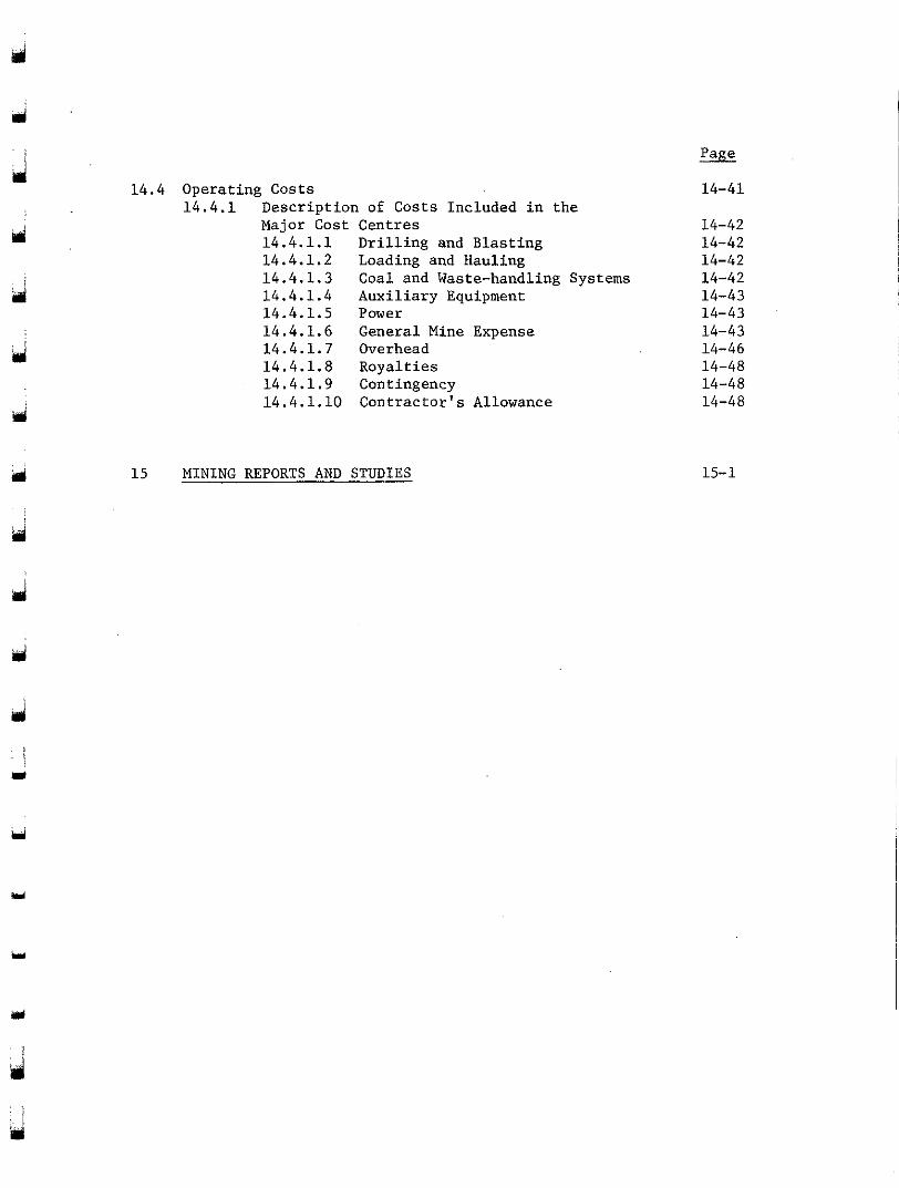
14.4 Operating Costs 14.4.1 Description of Costs Included in the
Major Cost Centres 14.4.1.1 Drilling and Blasting 14.4.1.2 Loading and Hauling 14.4.1.3 Coal and Waste-handling Systems 14.4.1.4 Auxiliary Equipment 14.4.1.5 Power 14.4.1.6 General Mine Expense 14.4.1.7 Overhead 14.4.1.8 Royalties 14.4.1.9 Contingency 14.4.1.10 Contractor's Allowance
15 MINING REPORTS AND STUDIES -
14-41
14-42 14-42 14-42 14-42 14-43 14-43 14-43 14-46 14-48 14-48 14-48
15-1
VOLUME 2
3
Y
d
ij
d
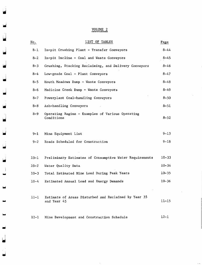
- No. - LIST OF TABLES
8-1 In-pit Crushing Plant - Transfer Conveyors 8-44
8-2 In-pit Incline - Coal and Waste Conveyors 8-45 8-3 Crushing, Stacking Reclaiming, and Delivery Conveyors 8-46
8-4 Low-grade Coal - Plant Conveyors 8-5 Houth Meadows Dump - Waste Conveyors 8-6 Medicine Creek Dump - Waste Conveyors 8-7 Powerplant Coal-handllng Conveyors
8-8 Ash-handling Conveyors
8-9 Operating Regime - Examples of Various Operating Conditions
9-1 Mine Equipment List
9-2 Roads Scheduled for Construction
8-47
8-48
8-49
8-50
8-51
8-52
9-13
9-18
10-1 Preliminary Estimates of Consumptive Water Requirements 10-33
10-2 Water Quality Data 10-34
10-3 Total Estimated Mine Load During Peak Years 10-35
10-4 Estimated Annual Load and Energy Demands 10-36
11-1 Estimate of Areas Disturbed and Reclaimed by Year 35 and Year 45
12-1 Mine Development and Construction Schedule
11-15
12-1
d
d
iri
d . . i :
r
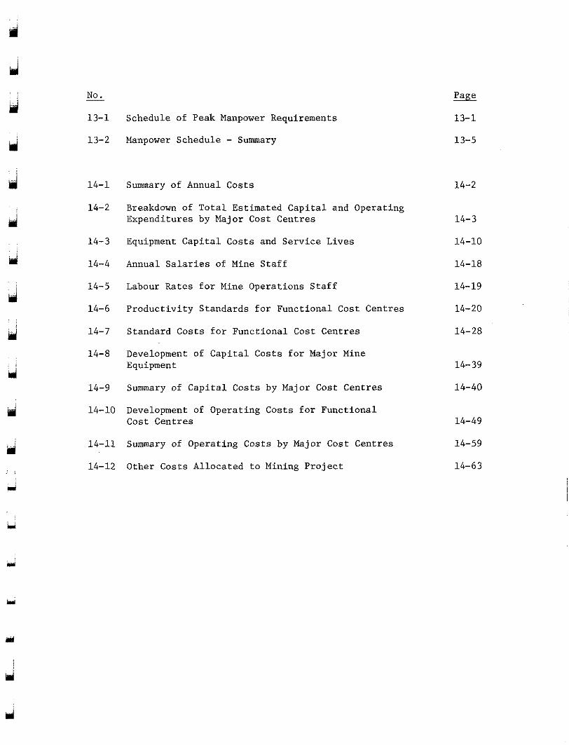
No. -
13-1
13-2
14-1
14-2
14- 3
14-4
14-5
14-6
14-7
14-8
14-9
14-10
14-11
14-12
Schedule of Peak Manpower Requirements
Manpower Schedule - Summary
Summary of Annual Costs
Breakdown of Total Estimated Capital and Operating Expenditures by Major Cost Centres
Equipment Capital Costs and Service Lives
Annual Salaries o f Mine Staff
Labour Rates for Mine Operations Staff
Productivity Standards for Functional Cost Centres
Standard Costs for Functional Cost Centres
Development of Capital Costs for Major Mine Equipment
Summary of Capital Costs by Major Cost Centres
Development of Operating Costs for Functional Cost Centres
Summary of Operating Costs by Major Cost Centres
Other Costs Allocated. to Mining Project
13-1
13-5
14-2
14- 3
14-10
14-18
14-19
14-20
14-28
14-39
14-40
14-49
14-59
14-63
Iri
d
d
m
ui
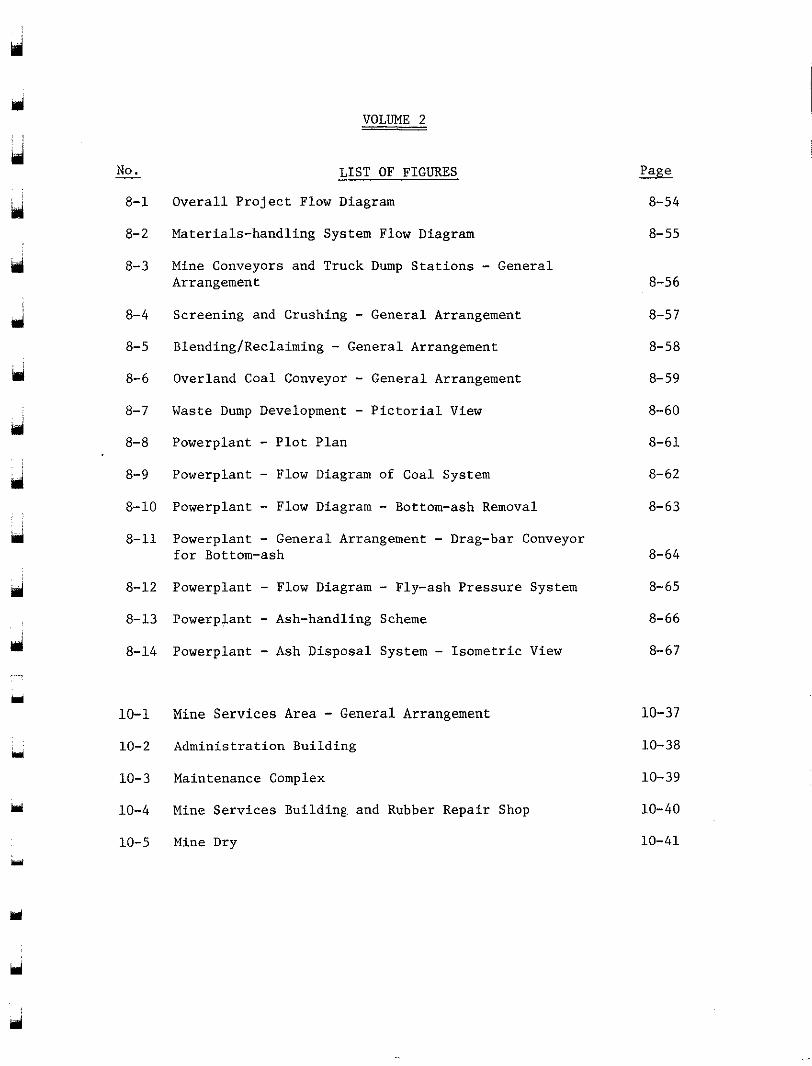
- No. LIST OF FIGURES - 8-1 Overall Project Flow Diagram
8-2 Materials-handling System Flow Diagram
8-3 Mine Conveyors and Truck Dump Stations - General Arrangement
8-4 Screening and Crushing - General Arrangement
8-5 Blending/Reclaiming - General Arrangement 8-6 Overland Coal Conveyor - General Arrangement 8-7 Waste Dump Development - Pictorial View
8-8 Powerplant - Plot Plan 8-9 Powerplant - Flow Diagram of Coal System
8-10 Powerplant - Flow Diagram - Bottom-ash Removal 8-11 Powerplant - General Arrangement - Drag-bar Conveyor
for Bottom-ash
8-12 Powerplant - Flow Diagram - Fly-ash Pressure System 8-13 Powerplant - Ash-handling Scheme
8-14 Powerplant - Ash Disposal System - Isometric View
10-1 Mine Services Area - General Arrangement 10-2 Administration Building
10-3 Maintenance Complex
10-4 Mine Services Building. and Rubber Repair Shop
10-5 Mine Dry
8-54
8-55
8-56
8-57
8-58
8-59
8-60
8-61
8-62
8-63
8-64
8-65
8-66
8-67
10-37
10-38
10-39
10-40
10-41
Y
d
Y
Y
No.
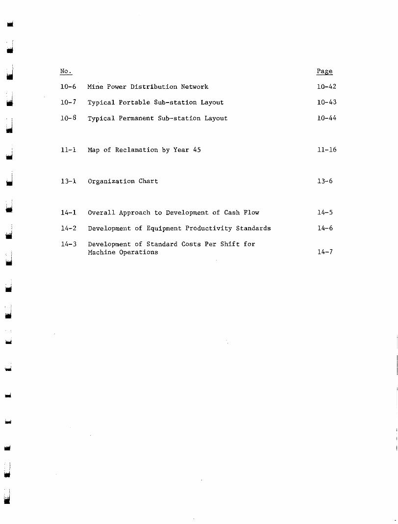
10-6 Mine Power Distribution Network
10-7 Typical Portable Sub-station Layout
10-8 Typical Permanent Sub-station Layout
-
11-1 Map of Reclamation by Year 45
13-1 Organization Chart
14-1 Overall Approach to Development of Cash Flow
14-2 Development of Equipment Productivity Standards
14-3 Development of Standard Costs Per Shift for Machine Operations
10-42
10-43
10-44
11-16
13-6
14-5
14- 6
14-7
u'
3
d
rri
Y
Y
1
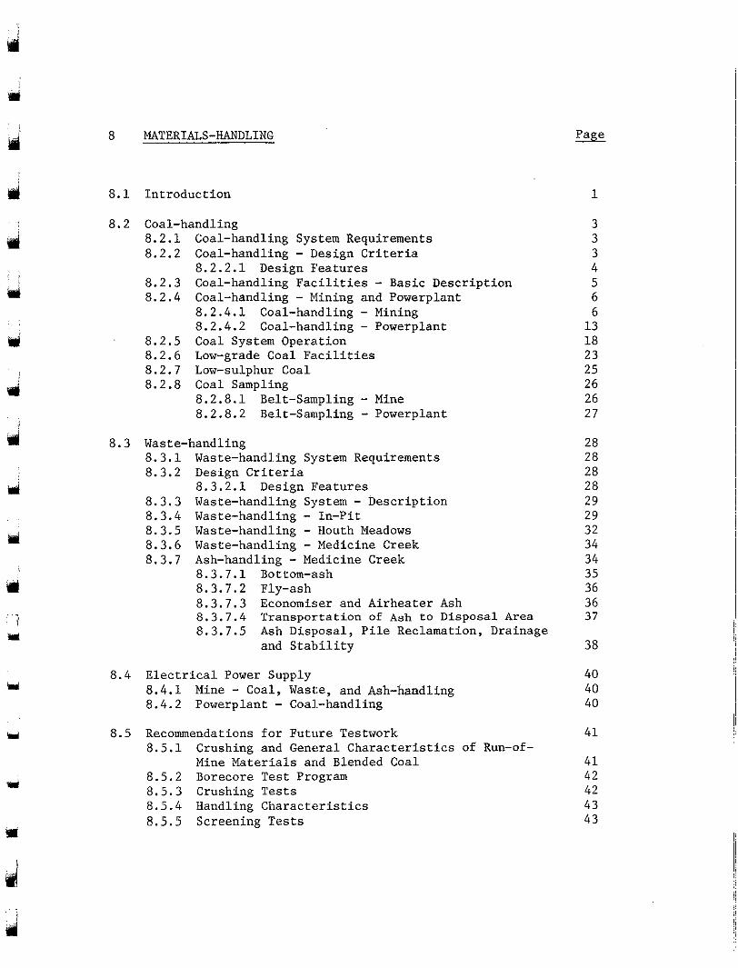
8 MATERIALS-HANDLING
8.1 Introduction 1
8.2 Coal-handling 8.2 .1 Coal-handling System Requirements 8.2.2 Coal-handling - Design Criteria 8.2.3 Coal-handling Fac:ilities - Basic Description
8 .2 .2 .1 Design Features
8 .2 .4 Coal-handling - Mining and Powerplant 8 .2 .4 .1 Coal-handling - Mining 8.2.4.2 Coal-handling - Powerplant
8 .2 .5 Coal System Operation 8.2.6 Low-grade Coal Facilities 8.2.7 Low-sulphur Coal 8.2 .8 Coal Sampling
8 . 2 . 8 . 1 Belt-Sampling - Mine 8.2.8.2 Belt-Sampling - Powerplant
8.3 Waste-handling 8 . 3 . 1 Waste-handling System Requirements 8.3.2 Design Criteria
8.3 .3 Waste-handling System - Description 8.3.4 Waste-handling - In-Pit 8.3.5 Waste-handling - Houth Meadows 8.3.6 Waste-handling - Medicine Creek 8.3.7 Ash-handling - Medicine Creek
8 .3 .2 .1 Design Features
8.3.7.1 Bottom-ash 8.3.7.2 Fly-ash 8 . 3 . 7 . 3 Economiser and Airheater Ash 8.3.7.4 Transportation of Ash to Disposal Area 8.3.7.5 Ash Disposal, Pile Reclamation, Drainage
and Stability
8.4 Electrical Power Supply 8.4.1 Mine - Coal, Waste, and Ash-handling 8.4.2 Powerplant - Coal.-handling
3 3 3 4 5 6
1 3 6
18 23 25 26 26 27
28 28 28 28 29 29 32 34 34 35 36 36 37
38
40 40 40
8.5 Recommendations for Future Testwork 41 8 .5 .1 Crushing and General Characteristics of Run-of-
Mine Materials arid Blended Coal 41 8.5.2 Borecore Test Program 42 8 .5 .3 Crushing Tests 42 8.5.4 Handling Characteristics 43 8 .5 .5 Screening Tests 43
a
tri
d
4ii
Mi
u
m
Y
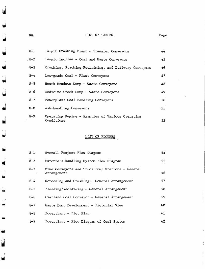
No. - - LIST OF TABLES
8-1
8-2
8-3
8- 4
8-5
8- 6
8- 7
8- 8
8- 9
8-1
8-2
8-3
8- 4
8-5
8-6
8- 7
8- 8
8- 9
In-pit Crushing Plant - Transfer Conveyors In-pit Incline - Coal and Waste Conveyors Crushing, Stacking Reclaiming, and Delivery Conveyors
Low-grade Coal - Plant Conveyors Houth Meadows Dump - Waste Conveyors
Medicine Creek Dump - Waste Conveyors Powerplant Coal-handling Conveyors
Ash-handling Conveyors
Operating Regime - Examples of Various Operating Conditions
- LIST OF FIGURES
Overall Project Flow Diagram
Materials-handling System Flow Diagram
Mine Conveyors and Truck Dump Stations - General Arrangement
Screening and Crushing - General Arrangement
Blending/Reclaiming - General Arrangement Overland Coal Conveyor - General Arrangement
Waste Dump Development - Pictorial View
Powerplant - Plot Plan Powerplant - Flow Diagram of Coal System
44
45
46
47
48
49
50
51
52
54
55
56
57
58
59
60
6 1
62
bi
d
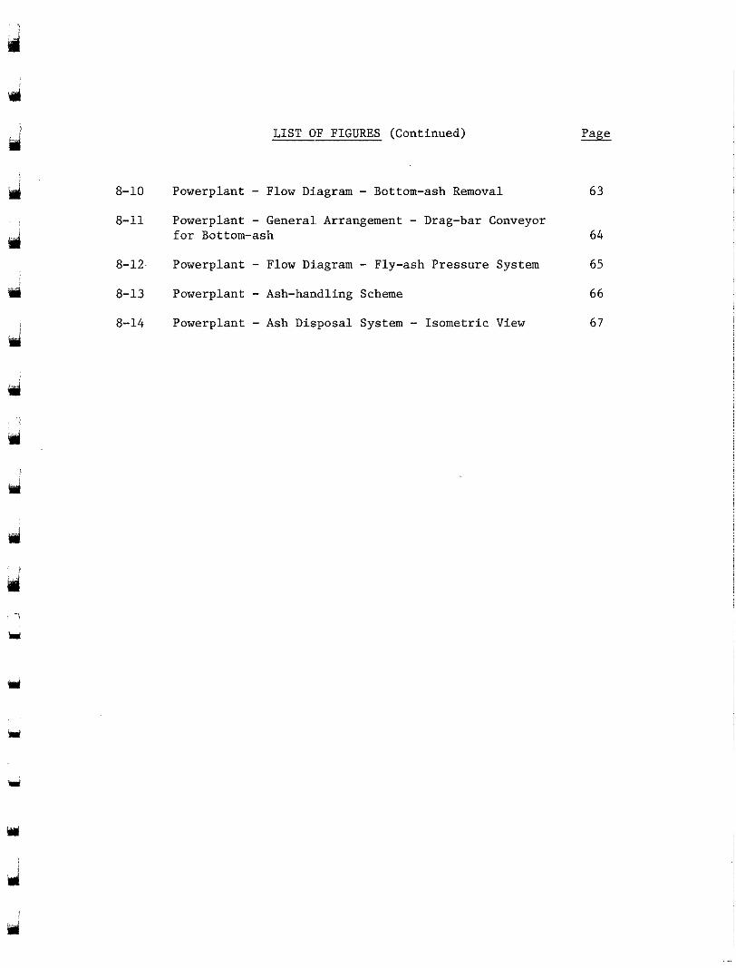
LIST OF FIGURES (Continued)
8-10 Powerplant - Flow Di.agram - Bottom-ash Removal 63
8-11 Powerplant - General. Arrangement - Drag-bar Conveyor for Bottom-ash 64
8-12. Powerplant - Flow Diagram - Fly-ash Pressure System 65
8-13 Powerplant - Ash-handling Scheme 6 6
8-14 Powerplant - Ash Disposal System - Isometric View 67
Y
3
SECTION 8
MATERIALS-HAN1)LING
8.1 INTRODUCTION
d
ad
Y
pl
Y
rrl
ri
handling systems employed in the different areas of the Hat Creek Project, This section of the report describes the various materials-
i.e. mining, powerplant, waste, and ash disposal. These systems receive and deliver the different materials to their respective destinations, bearing in mind the environmental impacts, the operational requirements,
reliability of all components. The systems, described in Section 8.2 the characteristics of the material, and costs as well as the safety and
handling"), have been developed by the following groups:
(1) Mining and Waste-handling - Cominco-Monenco Joint Venture, Simon-
9 , Coal-handling", and Section 8 . 3 "Waste-handling'' (including "Ash-
Carves of Canada Ltd., and B.C. Hydro Mining Department;
(2) Powerplant Coal-handling and Ash-handling - Integ-Ebasco/B.C. Hydro Thermal Engineering Department.
The different materials to be handled, and their destination points, are noted below:
Coal
With a range of heating values, above cut-off grade, i.e.
-
+9.3 W/kg (d.c.b.), containing varying amounts of waste materials such as clays and carbonaceous shales not removed separately in the mining process: This material will be delivered to the stockpile for blending prior to delivery to either the powerplant silos or the powerplant storage area.
Low-sulphur C&
lower sulphur content, will be delivered to the stockpile areas for Better-quality coal from D-zone of the deposit, with
blending, or direct to either the powerplant silos or to the powerplant storage area.
i
i
8 - 1
Low-grade Coal -
rri
d
d
(9
ui
4 !
Generally below cut-off grade, i.e. 7 MJ/kg - 9 . 3 MJ/kg
w i l l be de l ive red t o a dry beneficiat ion plant for up-grading, with (d .c .b . ) , conta in ing la rge a.mounts of waste materials: T h i s material
acceptab le material b e i n g d d i v e r e d t o t h e s t o c k p i l e s f o r b l e n d i n g w i t h
be rou ted t o t he waste dumps. Provis ion can readi ly be made t o d i v e r t the coals described above. Reject material with high ash content w i l l
t h e r e j e c t material t o a l t e r n a t i v e u s e s i f and when these develop.
Waste
(1) construction-grade material, i.e. sands and gravels for construct ion The run-of-mi.ne wastes can genera l ly be c lass i f ied as :
The materials w i l l be de l ivered to Houth Meadows, and i n later y e a r s t o of r e t a i n i n g embankments; (2) genera l mine waste, i .e. c lays , sha les .
Medicine Creek, for construc: t ion of embankments and dumps. Some waste ma te r i a l s w i l l a l so be reqdred for o ther cons t ruc t ion requi rements , i .e . road .cons t ruc t ion .
-
Ash -
This w i l l be de l ive red t o a dry-ash disposal area in Medicine Creek.
With th i s r ange of ma te r i a l s , t he re w i l l be many d i f -
Removed from the powerplant as f ly-ash and bottom-ash:
handl ing proper t ies w i l l be g rea t ly a f f ec t ed by Summer and Winter ferent handling problems which the design has taken into accoun't. Their
development of t h e mine and the phased i n s t a l l a t ion of fixed equipment, conditions; moisture content: could also pose problems. The gradual
such as conveyors and crushers , w i l l a l low the des ign of mining equip- ment to be modif ied as experience proves necessary.
Y
Y
8 - 2
cci
d
ri
8.2
8.2.1
COAL-HANDLING
Coal-handling System Requirements
The requirements of the Coal-handling System are:
(1) To provide a reliable supply of coal to the powerplant silos at a consistent quality, as defined in Section 5.2.1, "Powerplant Requirements", and at che quantities shown in Table 5-6;
( 2 ) To supply the required daily tonnage of performance coal, based upon an 18 out of 24-hour silo-filling sequence at full load conditions;
(3) To provide a reliable and readily available supply of higher quality lower-sulphur coal to meet the Meterological Control System or .plant upset conditions;
( 4 ) To handle.the clays in the coal, bearing in mind the climatic conditions;
(5) To allow for the considerable variation in the run-of-mine coal quality.
8.2.2 Coal-handling - Design Criteria
The coal-handling systems have been designed to the following criteria:
(1) A bulk density for conveyor capacity calculations of 800 kg/m3;
(2) A maximum slope for conveyors of 14'; for capacity calculations, a surcharge angle of 25 for materials, and a 35 troughing angle for conveyor idlers; all conveyors designed to start-up under full load conditions.
0 0
(3) The Conveyor Equipment Manufacturers' Association Handbook for belt load, friction factors, power calculations, and so forth.
8 - 3
ol
i ul
d
d
Mi i
n
Y
w
w
relevant sections. The individual conveyor capacities are discussed in the
8.2.2.1 Design Featurls
into the system to handle the variety of materials and to provide both safety and reliability.
Many imp0rtan.t design features have been incorporated
Further test work on the materials must be carried out before detailed engineering (of these systems can proceed. This is discussed further in Section 8.5.
All chutes, t.ransfer hoppers, and surge bins will be designed with slopes to reduce the incidence of material sticking to the walls. Conveyor transfer and loading points will be installed on the horizontal wherever possible, and impact rollers will be incorporated for conveyor belt protection. Skirtboards will also be fitted to conveyor transfer points to :provide for safe and effective load control. This is especially important on inclined conveyors carrying lump material. Magnets and metal detectors will be installed to protect equipment from damage by tramp metal.
Dust-control measures will include water sprays for dust suppression and/or dust collection systems at transfer points. Open conveyors will be fitted wit'h dust covers where necessary and practical.
matic sprinkler systems in transfer houses and galleries, and fire hydrants in other areas. The Fire Protection System for the coal- handling in the powerplant is part of a comprehensive Fire Protection System planned for the entire powerplant. This greater system bas not been engineered in any detail, but it will include, as a minimum., detection and sprinkler-deluge devices for enclosed galleries an.d under-
piles. ground conveyors with fire hydrants to protect open conveyors and stock-
Fire protection systems will consist generally of auto-
All stockpiles will be designed to minimize spontaneous combustion. This will be achieved by compacting dead piles and ensuring that live piles are consumed within a short time, usually two we.eks.
Comprehensive control schemes will be installed for both the mine and powerplant conveying systems. At the interface of the two areas, special care has been taken to integrate the systems.
wi i
d
8 - 4
PPJ
u
Y
I.I
m
u
and devices. These are desigsned to ensu re s a fe and r e l i a b l e o p e r a t i o n The con t ro l schemes inco rpora t e ce r t a in s a fe ty f ea tu re s
of t h e conveyor system and ear ly detect ion of condi t ions potent ia l ly damaging to the conveyors or associated equipment , or causing excessive s p i l l a g e of material. These include:
(1 ) Sequen t i a l s t a r t i ng and s topping of a l l p i e c e s of equipment forming one l i n e of t r anspor t a t ion ;
( 2 ) Chute-plugging switches which detect the blockage of a chute and s top the system;
(3) Safety cords along the conveyors which allow manual stopping of t h e conveyor l ine in emergencies ;
( 4 ) Side t r ave l swi t ches which s t o p t h e conveyor i n case of excessive of f -cent re movement of .the b e l t ;
(5) Low-speed switches which s top t he conveyor in case the speed drops below normal. These a l so p revent the s ta r t -up of the preceding conveyor u n t i l t h e conveyor on which the swi tch i s i n s t a l l e d h a s reached i ts normal speed;
(6) Belt-tensioning devices and con t ro l s t o ensu re t ha t t he co r rec t operating tension has been reached before loading the conveyor;
( 7 ) Overload protection devices for motors and conveyor b e l t s ; t h i s f e a t u r e w i l l shu t down upstream equipment a t a predetermined set- point to minimize overload hazards;
(8) Holdbacks to p reven t an inc l ined conveyor from running backwards under load;
(9) Torque-limiting devices to prevent over-tensioning of t h e b e l t dur ing s ta r t -up .
8.2.3 Pro jec t Coal F a c i l i t i e s - Basic Description
th ree ope ra t iona l areas shown on Figure 8-1. The proposed project coal system can be divided into the
rri 8 - 5
d . .
9
hi
Y
Y
Operation 1: Mining, processing, blending, and storing, adjacent to the mine;
Operation 2 : Reclaiming, loading, and delivery to the powerplant;
Operation 3 : Receiving, storing, and handling at the powerplant.
Operations 1 and 2 fall under the jurisdiction of the mine. Operation 3 is under the jurisdiction of the powerplant.
The three operations are described in detail below. In the detailed engineering phase, the engineering specifications for all handling equipment will be correlated to permit standardization of major components where practical.
8.2.4 Coal-handling - Mining and Powerplant
8 .2 .4 .1 Coal-handling - Mining
consists of two separate operations. The operations and their main A s noted in Section 8.2.3, the mine Coal-handling System
components are described below. The total quantity of performance coal to be delivered to the powerplant is 331 x l o 6 t, with a peak annual requirement of 11.64 x l o 6 t in Year 13. Figure 8-2 shows the system
System will be located in th'e Coal Surge Bin House. flow diagram. The main control room for the mine Materials-handling
(1) Mining, Processing, Blending, and Storing (Operation 1)
1. Truck Dump Stations
Three dump stations are proposed for the full capacity mining operations over the life of the mine. Located adjacent to the
stations, designed to handle all run-of-mine material, will be built in inclined in-pit conveyors at the Northern end of the proposed mine, the
sequence as the pit deepens. The first, near the surface, will be installed during the pre-production phase; the second in Year 8 , approxi- mately half-way down the incline; and the third in Year 2 0 , at the bottom of the incline. Two dump stations will normally operate at any one time.
8 - 6
Y
J
d
i
1.I
nd
A s shown i n Fi.gure 8-3, a dump s t a t i o n w i l l cons i s t of a series of s epa ra t e dump pocke.ts, each designed to handle a sepa ra t e mater ia l . This sec t ion dea ls on ly wi th .coa1; low-grade coa l and waste ma te r i a l s are descr ibed in Sect ions 8 .2 .6 and 8 . 3 , respec t ive ly .
hydraul ic shovels will b e d e l i v e r e d a t a peak r a t e of 3,200 t / h t o coa l pockets (Ml, M2) a t one of t h e dump s t a t i o n s .
Coal loaded iato 77-t rear dump haulage trucks by 10.7 m3
c o a l from r e a r dump t rucks . A 600 mm square g r izz ly , cover ing the hopper , sc reens o f f overs ize pe t r i f ied wood and boulders , which are disposed of by front-end loader and t ruck. A t the planned production rates, two pockets w i l l b e r e q u i r e d . I n i t i a l l y , t h e s e w i l l b e i n s t a l l e d a t t h e f i r s t dump s t a t i o n . However, a s t h e mine deepens and truck haulage dis tances increase, t:hey w i l l be re located to the second and t h i r d s t a t i o n s , as requi red . A th i rd pocket (M9) w i l l be required when
of c o a l t o two dump s t a t i o n s , g i v i n g a d d i t i o n a l f l e x i b i l i t y . the second dump s t a t i o n becomes operat ional . This w i l l a l low de l ivery
Each coal pocket , wi th a capac i ty of 300 t , w i l l r ece ive
2. Primary Crushing
1 ,600 t /h maximum by an aprou feeder, which discharges the coal 'to a Run-of-mine coa l w i l l be fed from each dump-hopper a t
ro l le r sc reen working in conjunct ion wi th a Siebra crusher . The r o l l e r sc reen w i l l a l low coa l a t -200 mm to pass through, while larger :pieces are crushed by an overhead crushing mechanism. Uncrushable material , such as p e t r i f i e d wood, l i f t s t h i s mechanism and passes through to a short re jects-conveyor , which discharges the mater ia l to a s t o c k p i l e f o r d i sposa l by a front-end loader and truck. Coal a t -200 mm w i l l .be d i scharged to a t r a n s f e r conveyor and delivered to the mine Coal Conveyor. Table 8-1 g i v e s d e t a i l s of t he conveyors i n t h i s area.
3 . Mine Coal Conveyor
The mine Coal Conveyor (M8A), with 1,400 mm-wide steel c o r d b e l t and designed to handle 3 ,200 t /h , rece ives coa l from t 'he
House to the secondary screening and crushing plant . The conveyor t ransfer conveyors and d e l i v e r s i t v i a t h e Conveyor Drive and Transfer
i n i t i a l l y w i l l cons i s t of one f l i g h t , w i t h two more (M9A, MlOA) being i n s t a l l e d i n series to fo l low the mine development sequence as no ted above. Table 8-2 g i v e s d e t a i l s of the conveyors. I n the . even t of a breakdown of th i s sys tem, a back-up is provided by use of t h e Low-grade Coal Conveyor descr ibed in Sect ion 8 .2 .6 . A s shown i n F i g u r e 8-4, a
w i l l be used to de l iver coa l from t h e Low-grade Coal Conveyor (M8D) t o bypass conveyor (Cl) located in the Conveyor Drive and Transfer House
t h e Coal Transfer Conveyor (C2) and to the Screening and Crushing Plant.
8 - 7
P
d
4. Secondary Screening and Crushing
Coal received from the mine Coal Conveyor (M8A), o r from t h e Bypass Conveyor (Cl ) , is discharged to a 1,400 mm-wide t r a n s f e r conveyor (C2) and de l ive red t o a set of four surge b ins , as shown on Figure 8-4. Table 8-3 g i v e s d e t a i l s of t he conveyors i n t h i s a r ea . A
Reclaim from each of t h e 150 t-capacity b ins a t 1 , 0 0 0 t / h w i l l be by r o t a t i n g chute w i l l d i s t r i b u t e t h e c o a l feed equal ly i n t o t h e b ins .
apron feeders (C3A, 3B, 3C, 3D). Each feeder w i l l d i s cha rge t o a screen-feed conveyor (C4A, 4B, 4C, 4D) de l iver ing to the Screening and Crushing Plant. The coa l w i l l be discharged from each delivery conveyor t o a two-deck inc l ined v ib ra t ing s c reen (C5A, 5B, 5C, 5D). The top decks of these screens w i l l b e f i t t e d w i t h 50 mm square woven wire s u r f a c e s t o c l a s s i f y by s i z e a t 50 mm nominal. The lower deck w i l l be f i t t e d w i t h m i l d steel p l a t e and function as a carrying deck.
crusher (C6A, 6B, 6C, 6D), si.zed to handle up t o 350 t / h f o r r e d u c t i o n t o -50 mm. Screen underflow w i l l be carr ied forward to blend wi1:h t h e
d i v e r s i o n t o e i t h e r of two pa.ralle1 conveyors (C7A, 7B). One of these crusher product. The -50 mm coa l w i l l g r a v i t a t e t o a two-way chu te fo r
desc r ibed i n Sec t ion 8.2.6. two conveyors w i l l a lso recei .ve coal f rom the low-grade c o a l f a c i l i t i e s
Screen overflow w i l l be discharged to an impact-type
(C8A, 8B), which then deliver. the coal to the Sampling House. A f u r t h e r t r a n s f e r of t h e c o a l t o a thi . rd pair of conveyors (C9A, 9B) w i l l occur i n th i s house . E i ther of thi .s th i rd pair of conveyors w i l l de l ive r t he c o a l t o t h e S t o c k p i l e Conveyor (C10) i n the Blending/Storage Yard, or to the Reclaim/Bypass Conveyor (C12) i f t h e c o a l i s t o b e d e l i v e r e d d i r e c t l y to the powerplant .
These conveyors transfer to a second pair of conveyors
l i n e s and a second conveyor I.ine t o t h e Blending Stockpile Area censures maximum r e l i a b i l i t y .
T h e p rovis ion of four separate screening and crushing
5. Blending/Storage Piles
The purpose of the Blending/Storage System is two-fold: (1) to smooth out the shor t - te rm var ia t ions in the qua l i ty of coa l received from the mine; and (2) to p rovide a su rge capac i ty i n t he f l ow of c o a l from t h e mine i n case of breakdown of t h e Overland Conveyor t o the powerplant or powerplant problems.
The c rushed coa l , a t -50 mm, from the c rush ing p lan t o r low-grade coa l bene f i c i a t ion p l an t , w i l l vary i n q u a l i t y from thls cut- off grade of 9 . 3 W/kg (dry basis) to about 22.0 W/kg. The average
id
md
Y
m
8 - 8
rrl
id
i,
w
U
quality of the coal to be delivered to the powerplant will be 18 MJ/kg. Therefore, the blending system selected must be capable of producing performance coal. The qua1it:y of coal delivered to, and reclaimed from,
Section 8.2.8. This will allow the mine coal production schedule. to be the blending piles will be continuously monitored, as described i n
adjusted to ensure the delivery of performance coal to the powerplant.
location of the blending/storage piles, and a study to determine their location was carried out. The study considered the powerplant st.orage requirements to eliminate unnecessary duplication of facilities, provide a reliable supply, furnish operational control, ensure efficiency of operation, and meet environmental standards.
Several factors were considered in selecting the size and
stockpile size to suit the predicted blending requirement for the varying qualities of coal and on mine dust, were also taken into con- sideration. The location selected for the piles is adjacent to t:he mine mouth in an area that has room for expansion.
Earlier studies by the Cominco-Monenco Joint Venture on
The selected layout of the facility, as shown on Figure 8-5, comprises two regular blending piles, each with a maximum 300,000 t
mance coal for full-load operation of the powerplant. Normally, one capacity. Each pile will be equal to about one week's supply of perfor-
pile is being built while the other is being reclaimed.
The operating size of the blending piles will vary
plant. These forecasts enab1.e the mine to schedule coal production and according to the long-term an.d short-term coal forecasts of the power-
will also be reduced by such planning and scheduling. The size of the blending pile construction accordingly. Spontaneous combustion hazards
piles will also vary in the early years of operation as the powerplant construction proceeds to full. production from the four generating units, i.e. from 500 MW to 2,000 MW. Quality control of the coal in the piles during these periods is assured by varying the pile construction technique, as given in Section 7.6.3.
the space limitations of the site and the selection of 300,000 t as the The size and <:onfiguration of the piles is influenced by
size of a blending pile. Other factors include the size and availability of the required equipment, and the stockpile efficiency, which is deter- mined by the ratio of pile length to width. The selection of the blending method is influenced by the method in which a pile is deposited and reclaimed. The Windrow Method, as shown on Figure 8-5, has been
The Windrow Method gives better blending efficiency by reducing -particle selected over the Chevron Method, as the most suitable for Hat Creek.
segregation and reduces dustfng potential.
8 - 9
J
d
il
d
i
stacker receiving coal at 3,200 t/h from the Central Stacking Conveyor
will deposit the coal by the Windrow Method. Normally, the stacker (Cll), 1,400 mm wide, via a travelling-belt tripper. The luffing boom
constructs a pile of 100 windrows, but is designed to construct a pile of 200 windrows. The stacker has its travelling speed controlled by a weigh scale, and is in other respects automatically controlled. This
maximum use of the storage space and gives better assurance of quality. enables windrows of uniform cross-section to be built, which allows
Table 8-3 gives details of the conveyors in the area.
The system will. use a'slewable, luffing, rail-mounted
and is able to begin building the other pile with a minimum of delay.
Major specifications of the stacker are:
Capacity - 3,200 t/h Boom length - 55 2 Slewing arc Lifting height - 18 m
- 200 minimum
Travelling speed - 3 to 30 m/min.
through the Blending/Storage System after crushing. However, as de- Normally, all coal arriving from the mine would p a s s
scribed in Section 8.2.7, a bypass will be provided to allow direct delivery to the powerplant o f low-sulphur coal to meet MCS conditions or to replenish low-sulphur storage stockpiles at the powerplant.
The stacker, aEter building one pile, slews through 180'
As recommended in the CMJV Dust Study, certain features have been incorporated into the Blending/Storage System. A s shown on
minimize dusting potential, considering the prevailing wind directions, Figure 8-5, the piles will be specially contoured and oriented to
berm along the Southern edge of the piles will provide a windbreak. A i.e. in a North-East - South-West direction. A specially constructed
dust-suppression system using water guns will also be installed. The stacker discharge boom will be equipped with a telescopic chute to reduce dusting in the stacking operation, and all transfer points on the system will be equipped with dust-suppression equipment.
Normally, because of the short residence time, the blending/storage piles would not be compacted. Provision would be made
combustion. for compacting if this should prove necessary to prevent spontaneous
3
i
i
8 - 10
d
m
3
Y
Y
L
j
d
(2) Reclaiming, Loading, and Delivery (Operation 2)
1. Reclaiming and Loading
To ensure the delivery of performance coal in the desired
between powerplant and mine operations. The powerplant requirements for quantities to the powerplant, close co-ordination will be required
short-term and long-term electricity production schedules. Accurate coal of performance quality will be advised in advance, according to
forecasting of coal requirements is necessary to enable the mine to schedule production of the required quantity,and quality of coal to the Blending System.
bucketwheel reclaimer with a reversible shuttle conveyor. The reclaimer The Reclaiming System consists of a single rail-mounted
is also equipped with a moving rake which moves the coal down the face of the pile to the bucketwheel moving across the face at the fool: of the pile. The rake aids in the blending of the coal and allows for a safer operation, i.e. it does not a. l low undercutting of the pile. As shown on Figure 8-5, the reclaimer reclaims blended coal from one pile, feeding it to the Reclaim/Bypass Conveyor (C12) on the South side of the Blending/ Storage Yard. After reclaimi.ng one pile, the reclaimer travels back to the Eastern side of the yard, where a transporter car transfers it to the other pile which the stac:ker has built. After reconnection of the power supply, the Shuttle Conveyor will be repositioned and its direction of travel reversed.
Reclaiming operations will then recommence, with -the reclaimed coal being fed to the other 1,400 mm-wide reclaim conveyor (C13) on the Northern side of the yard, which will deliver it to a collecting conveyor ((214) 1,1100 mm wide feeding the Overland Coa.1 Conveyor. Stacking operations will then resume to rebuild the first pile.
The reclaimer has a maximum capacity of 3,000 t/h. Normal flow to the powerplant is 2,500 t/h, based upon filling t'he
delivery facilities could be operated at up to 3,000 t/h to simulta- powerplant silos for 18 out of 24 hours. When necessary, the re,claim/
neously fill the powerplant silos and replenish the dead stockpile at the powerplant after prolonged outage of the Reclaim/Delivery System.
The most important features of the reclaimer are:
- track mounted with reversible operation; - bridge span between tracks - 51 m;
8 - 11
td
d
d
Y
rl
1,
u
Y
- number of bucketwheels - 1;
- capac i ty - v a r i a b l e from 3,000 t / h t o 500 t / h .
c o n s i s t s of a po r t ab le conveyor supplied with coal from front-end. loaders and dozers, which w i l l be supplied from mine operat ions. The c o a l is de l ive red t o t he Reclaim Conveyor v i a a hopper.
An emergency back-up system is also provided. This
2. Overland Conveyor
A s i n g l e conveyor i n f o u r f l i g h t s (C15, (216, C 1 7 , and powerplant Receiving Conveyor 1 ) c a r r i e s c o a l from the reclaiming area
cord be l t , normal ly opera tes a t a capacity not exceeding 2,500 t/ 'h, t o a Main Transfer House a t the powerplant. This conveyor, with steel
based upon an 18-hour s i l o - f i l l i ng s equence . The maximum design capaci ty of the Overland Conveyor, however, is 3,000 t /h to rep len ish powerplan t s t o c k p i l e s as well a s d e l i v e r 2,500 t /h to the powerplan t s i los . Tables 8-3 and 8-7 g i v e d e t a i l s of t h e conveyor f l i g h t s and Figure 8-6 shows the l ayou t .
f i l l s e c t i o n s t o s u i t t h e 1an.d contours. Adequate clearance is provided to permit clean-up of s p i l l a g e . It passes underneath the project: access r o a d i n one location. A 5 m-.wide road allowance i s included a longside the conveyor for inspect ion and maintenance.
The conveyor is mounted near ground l eve l , w i th cu t and
The conveyor i.s covered to prevent dust ing and, in c e r t a i n a r e a s , a t o t a l l y e n c l o s e d g a l l e r y may be used, e.g. where deep snowdrifts can occur. An al1.owance for such enclosures has been in- c l u d e d i n t h e c a p i t a l c o s t of the conveyor.
conveyors has been c a r r i e d out. However many overland conveyors are provided, there i s still a r l . sk tha t the coa l supply may be in te r rupted . Therefore, as an insurance, a minimum supply of 14 days ' coal a t con-
yard. T h i s s t o r a g e f a c i l i t y i s desc r ibed i n Section 8.2.4.2. This t inuous fu l l - load condi t ions w i l l be stored in the powerplan t s to rage
amount of s to rage i s su f f i c i en t t o ma in ta in ope ra t ion of the powerplant fo r t he l onges t p red ic t ab le ma jo r breakdown, i.e. the complete replace- ment of one conveyor b e l t .
A study of t h e r e l i a b i l i t y of a number of overland
Based on th is reasoning , a single overland conveyor has been selected. The provis ion of fou r f l i gh t s , w i th a change i n 'd i rect ion
v a t i v e r o u t e f o r t h e conveyor l i ne t o be chosen . Th i s r e su l t s i n occurr ing a t t h e end of t h e f i r s t and t h i r d f l i g h t s , a l l o w s a conser-
8 - 12
. . i
d d
Lj
Y
,
M
d
ri
3
Y
m
3
shallower inclines for the conveyor and access roads compared with a direct route, minimizes contact with the highway, and reduces belt tensions to allow selection of proven belts giving better assurance of reliability.
8.2.4.2 Coal-handling System - Powerplant (Operation 3)
General
The powerplant Coal-handling System includes:
(1) A facility for receiving the discharge from the Overland Conveyor System;
(2) A Silo-filling System to deliver coal t o the silos above the pulverizers from the Overland Conveyor or from powerplant s,torage;
( 3 ) Powerplant storage and reclaiming facilities.
requirements, are assembled in the Station Design Manual (SDM) compiled by the powerplant consultant, Integ-Ebasco.
Powerplant coal-related design data, including coal
coal required by four units at full load for 24 hours. In 18 hours, the Silo-filling System would provide the
Sumary of Components
The main components of the powerplant Coal-handling System, in addition to the Receiving Conveyor (1) from the powerplant perimeter, are:
(1) The Main Transfer House, including a 600 t surge bin and c:cushers for frozen coal;
(2) Conveyors 4A and 4B from Main Transfer House to Surge Bins 1 and 2;
( 3 ) Surge Bins 1 and 2 in the Auxiliary Bay;
( 4 ) Feeders and conveyors for transfer from Surge Bins 1 and 2 to silo conveyors;
8 - 13
ei'
d
. . i
3
u
3
(5) Silo conveyors;
(6) Silos;
(7) Stocking-out Reclaiming Conveyor 18;
(8) Stacker-reclaimer and live storage facility;
(9) Dead-storage facility, mobile equipment, and emergency reclaim facilities;
(10) Powerplant coal-handling control facilities;
(11) Powerplant coal-handling sampling/testing facilities.
diagrammatically as part of the overall project coal system. Figure 8-1 shows the powerplant Coal-handling System
the plot plan of the powerplant, Figure 8-8. Major features of the coal-handling layout are sh.own on
the powerplant. Figure 8-9 shows the detailed coal-handling diagram for
powerplant Coal-handling System. Table 8-7 lists the conveyors and belt-feeders for the
Description of Components
A description of the powerplant Coal-handling System follows :
1. Final Flight of the Overland Conveyor
The Receiving Conveyor (1) at the powerplant is 8n extension of the Overland Conveyor and operates as part of that complete system. This conveyor (1) is a single, covered belt, above ground, and running North/South on the East side of the cooling towers. Should the Overland Conveyor System be unavailable for any reason, it does not preclude operating the remainder of the powerplant Coal-handling System or prevent the supply of coa.1 to the silos, because the powerplant has storage under its direct con,trol, as described in items 9 and 10.
(1) are: Capacities of the Overland Conveyor and Receiving Conveyor
1
8 - 14
mi
Normal maximum 2 ,500 t /h
Peak capacity 3,000 t / h
Normally, the Overland Conveyor w i l l empty before being stopped. Should the coal on t h e Overland Conveyor have t o be dumped, t h e s i l o i n t h e T r a n s f e r House is used. The Overland Conveyor can hold about 900 t . Excess coal w i l l be dumped via the Excess Discharge Conveyor (17) t o t h e ground.
2. Main Transfer House
This Transfer House is t h e main coa l rece iv ing and d i s t r ibu t ion po in t fo r t he powerp lan t . I t w i l l con ta in a 600 t surge b i n and t ransfer conveyors for normal del ivery of coa l to the powerplan t s i l o s o r , when desirable or necessary, to the powerplant Storage System.
speed in le t feeders , a re inc luded for recrushing f rozen coa l rec la imed from t h e s t o r a g e areas in Winter, i f and when necessary. Screens may be
alternatives. Normally, the. crushers are bypassed. Protect ive devices included ahead of the c rushe . r s a f te r a f u l l e v a l u a t i o n of crusher
such a s me ta l de t ec to r s are provided.
Two 100X-capacity frozen lump crushers , wi th var iab le-
and f i r e - p r o t e c t i o n f a c i l i t i . e s . The Transfer House i s heated and includes dust-control
3. Powerhouse Conveyors (4A and 4B)
Two 2,500 t / h i n c l i n e d Powerhouse Conveyors (4A .and 4B), housed i n a common enclosed and heated gallery, carry coal from t h e Main Transfer House t o t h e Surge Bins (1 and 2) in the Auxiliary Bay of t h e Powerhouse. These conveyors enter t h e Powerhouse between Bo i l e r s 1 and 2. Normally, one conveyor operates and t he o the r is on standby.
4. Powerhouse Surge Bins and Transfer Conveyors
Surge Bins ( I and 2), each of 100 t capac i ty , a re loca ted respectively between Boiler:; 1 and 2 and Bo i l e r s 3 and 4 i n t h e A u x i l i a r y Bay. Surge Bin 1 is f e d d i r e c t l y from t h e Powerhouse Conveyors (4A and 4B). Surge Bin 2 i s fed from the Powerhouse Conveyors (4A o r 4B) by two 2,500 t / h T r a n s f e r Conveyor:; (5A and 5B). Normally, t he su rge b ins a r e fed by e i t h e r of t he i nc l ined Powerhouse Conveyors (4A or 4B) i n con- j u n c t i o n w i t h e i t h e r of Transfer Conveyors (5A o r 5B).
Y
rri : ~i .
bd
'3
3
d 8 - 15
i d
J 5. Powerhouse Surge Bin Outlet Feeders and Conveyors
Discharge from the Powerhouse Surge Bins (1 and 2) i s by var iable-speed discharge feeders and manually-operated gates. The feeders supply ing the ad jacent s i lo conveyors feed d i rec t . Those supply ing the ou ter s i lo conveyors feed to 400 t / h In t e rmed ia t e Conveyors (6A, 6B, 7A, and 7B). For each conveyor there i s a standby of equal capac i ty .
19
id i
d
prl
csi . ~1
Y
m
Y
6. S i l o Conveyors
s i n g l e s i l o - f i l l i n g conveyor (10A/B, 11 A/B, 12 A/B, and 13 A/B) of Over t h e row of f o u r s i l o s on each s ide of each bo i le r , a
capac i ty 400 t / h e a c h d e l i v e r s c o a l t o a t r a v e l l i n g t r i p p e r , which f i l l s t h e s i l o s .
c o a l demand f o r f u l l - l o a d bo:Ller operations can be completed in 18 hours
However, the system design i:; f l e x i b l e and a l lows cont inuous f i l l ing out of a 24-hour per iod, is ten ta t ive ly p lanned as the opera t ing mode.
wi th vary ing bo i le r loads .
S imul taneous f i l l ing of a l l rows of s i l o s , s o t h a t d a i l y
Ind iv idua l s i .Los a r e f i l l ed on a " layer ing" bas i s .
The s i l o - f i l l i n g o p e r a t i o n i s automated t o a reasonable degree, but i s under constant supervision from the coal-handling; control panel , f rom which the f i l l ing ra te can be manual ly adjusted.
Key s igna ls (e .g . low s i lo- leve l a la rms) are r e p e a t e d i n t h e b o i l e r c o n t r o l p a n e l s .
7. S i l o s
E igh t s i l o s , fou r on each s i d e , are provided for each b o i l e r . Each s i l o f e e d s one pulverizer. The s i los each ho ld up t o e ight hours ' capac i ty for one pu lver izer a t fu l l load wi th per formance coal. Normally, seven mills c a r r y f u l l l o a d . S i l o s a r e of c i rc :ular construct ion, wi th conical bot toms of s t a i n l e s s steel with a 78" slope. Manual gates a r e f i t t e d a t e a c h s i l o o u t l e t , and provis ion is made f o r emptying t h e s i l o c o n t e n t s i n a n emergency.
The s i l o gates, downpipes, feeders, and emergency emptying chu te s a r e part of t h e b o i l e r .
bd
8 - 1 6
8. Stocking-out Conveyor
A single 2,500 t/h conveyor (18) feeds from the Main Transfer House to the live storage area. It discharges to the stacker/ reclaimer.
would be made of enclosing this conveyor along with the live storage pile (see below).
Conveyor (18) is tentatively of the open type. A. study
9. Stacker/Reclaimer - Live Storage The base scheme includes a live storage pile of u.p to 2%
days' supply at full load (about 100,000 t) in two sections. This ensures that the powerplant has performance coal and low-sulphur coal
duction at all times, including short interruptions in the coal supply directly and promptly reclaimable to assure continuity of power pro-
from the mine.
in readiness for coal switching for the MCS. Lower-sulphur coal is stored at one end of the li.ve pile
at up to 2,500 t/h on the live storage piles adjacent to the track. A travelling, rail-mounted stacker/reclaimer stac:ks coal
The live storage piles are reclaimed regularly to avoid spontaneous combustion.
Reclaim from the uncompacted live storage piles is by the bucketwheel on the stacker7reclaimer. Alternatively, a bottom-reclaim system with ploughs may be used. Reclaim capacity is 2,500 t/h.
reasonable period, the powerplant could directly reclaim dry coal The live storage pile may be roofed so that, for a
regardless of climatic conditions.
10. Dead Storage
Adjacent to the live storage area, a compacted dead storage pile of approximately 30 days' capacity at full station load could be built. This would allow the powerplant to be self-sufficient
mine were to occur. The dea.d storage would be compacted to avoid for a reasonable period if a major interruption in coal supply from the
spontaneous combustion. This storage would be built by mobile equipment
dead storage is proposed. taking coal from the live storage area. A minimum of 14 days' supply in
Y
tsl
u
I
Y
'n
ml
8 - 17
ui
d
i
w
ri
'd
Reclaim would be by mobile equipment to the live storage reclaimer. Emergency reclaim hoppers and conveyors are also included.
live or dead storage can be rebuilt following heavy usage, while also The powerplanl: Coal-handling Plant is designed so that
receiving coal and filling silos at the normal rate of 2,500 t/h. Accordingly, the Supply System (operation 2) will have a maximum capacity of 3,000 t/h.
Part of the dead storage area would be stocked with lower-sulphur coal required for MCS operation.
It is anticipated that, in addition to giving the power- plant operators an assured supply of coal at all times and rapid retrieval of lower-sulphur coal, the live and dead storage facilities may also be used to ease temporary operating problems which may arise from difficult coal quality or other operational factors.
11. Other Powerplant Coal-handling System Features -
Many items of detailed engineering related to the coal system will be performed in the final design stage, particularly after the major boiler and coal-handling equipment is ordered.
Particularly important are:
(1) The basic control and instrumentation scheme, including the neces- sary sampling and testing facilities;
(2) Environmental protection (e.g. dust control, noise control).
8.2.5 Coal System Operation
General
Detailed operating regimes for the components of the project coal system can only be finalized when engineering has advanced into the detailed stage. However, the basic operational concepts are:
(1) Power production for the next period (say one month) will be planned ahead;
w
I ioi 8 - 18
i
!
!Id
ui
i
mi
Y
. ..
Y
The coal requirements will be determined and communicated t'3 both powerplant coal operators and to the mining operation;
Mine production will be scheduled to construct one blending pile, while coal from the other pile is reclaimed and delivered to the powerplant;
When a new blending pile is complete and the other pile is reclaimed, the stacker and reclaimer are interchanged and the process repeated;
In normal operation, coal deliveries will be balanced to powerplant consumption;
monitor delivered qualicy. The powerplant will also sample quality Sampling and quality control facilities in operations 1 and 2 will
of coal delivered to the silos;
The blending piles act ;as a surge between the mine and the Overland
between the Overland Conveyor and the silos. This allows reasonable Conveyor, and the powerplant stockpiles provide surge capacity
flexibility to maintain efficient operations in all areas despite temporary imbalance.
Planning has .recognized that there may be short periods of emergency when the quantity and quality of the supply of coal to the powerplant does not meet the requirements of the powerplant. Ta.ble 8-9 lists some of these possible situations and typical corresponding corrective actions. Strategically placed stockpiles are integrated with the mining and powerplant operations. This provides a means of dealing with emergencies without affecting electricity production.
The overriding concept in operation 3 , the powerplant coal operation, is to ensure reliability of power production, with coal of adequate quantity and quality available at all times.
Coal-handling Control System
will be centralized on a separate panel located in the main control room of Generating Units 1 and 2 in the powerhouse. Further consideration will be given t o the location of a separate panel in the Main Transfer House for remote control of the storage facilities. A programmable logic controller will be used for the Coal-handling System because of its flexibility and suitability for program changes. This may be
changes will be available to suit various layering techniques required integrated with the powerpla.nt process control computer. Program
for the mixing of coal in tbe silos and to change silo-filling programs when handling free-flowing or sticky coals.
The instrumentation and control of the powerplant: system
:, d The ob jec t ives of the Cont ro l System a r e :
(1) To provide an au tomat i c S i lo - f i l l i ng System i n which t h e rate of
coa l demand, short-term adjustments, h a n d l i n g a b i l i t y of t he coa l , f i l l and s i l o l e v e l s can b e v a r i e d t o meet predetermined powerplant
and a v a i l a b i l i t y of t h e coal-handling equipment;
(2) To provide manual selections and indications so t h a t t h e sy.; c tem can be operated manually;
(3) To provide opera t iona l p ro tec t ion of the Coal-handling System.
l e v e l s are a d j u s t e d t o s u i t t .he f low character is t ics of t he coa l and s i lo - f i l l i ng r equ i r emen t s . The readout f rom the be l t sca le on t h e t h i r d
room t o assist the ope ra to r s i n s e t t i ng t he l oad ing s equence . f l i g h t of the Overland Conveyor i s ava i l ab le i n t he powerp lan t con t ro l
S i l o f e e d r a t e s are based on un i t l oad , and s i l o o p e r a t i n g
In t e rmi t t en t ope ra t ion of t h e mine Reclaim System and overland conveyors w i l l be avoided.
bo i l e r house s i l o s . When handling free-flowing coal after t h e s i l o s are f i l l ed , t he powerp lan t ope ra to r s may d i v e r t t h e c o a l t o t h e i r s t o c k p i l e s o r i n s t r u c t t h e mine t o s t o p d e l i v e r y .
Coal delivered from the mine i s normal ly d i rec ted to the
sub-systems, each connected j.n independent series, a s d e s c r i b e d i n items 1 t o 6 below.
The powerplant Coal-handling System comprises several
p l a n t , and normal and emergency reclaim systems, discharge coal to the Main Transfer House Surge Bin. Each one is connected in independent series, wi th p lugged chu te con t ro l s i n t he i r d i scha rge chu te s l oca t ed above the surge bin. The b i n i n t h e Main Transfer House provides surge capacity for the above systems.
The coal-delivery sub-system from the mine, the power-
Surge Bins 1 and 2 i n t h e A u x i l i a r y Bay provide surge capac i ty fo r t he Powerhouse conveyors fed from the Main Transfer House.
An independen+: system for each row of f o u r s i l o s d e l i v e r s coa l from the Surge Bins (1 and 2 ) t o t h e s i l o s .
The powerplanc stockout sub-system i s in te r locked wi th the overland conveyors by a plugged chute detector below the var iable s p l i t t e r i n t h e Main Transfe:c House.
us
Y
w
3
ri
ui 8 - 20
d
d
J
l
d
w
A l l sub-systems interlocked i n series are provided with timers f o r s e q u e n t i a l start ing. I n i t i a t i o n of any stop control on any conveyor i n series automatica:lly stops a l l conveyors upstream of the conveyors on which the stop is made.
1. Overland Conveyors t o Surge Bins i n Main Transfer House
Receiving Conveyor (1) is p a r t of the Overland Conveyor
Main Transfer House. 1n i t i a t : t on of any s t o p of t he con t ro l s on t h e System, which i s inter locked with the high-level chute control i n , t h e
overland system or of t he va r :Lab le sp l i t t e r i n the T rans fe r House. s w i t c h e s o f f a l l equipment back t o t h e reclaimer a t t h e b l e n d i n g p i l e s .
2. Surge Bin i n Main Transfer House
Act iva t ion of t h e h igh leve l cont ro l au tomat ica l ly speeds
Act iva t ion of the plugged chute controls i n the chutes feed ing the surge up the d i scharge feeders and/or starts up the Excess Discharge Belt 1 7 .
b in s tops the Overland Conveyor System, t h e Reclaim System from I.ive s to rage (Conveyor 18), and t h e Emergency Reclaim System (Conveyors 19A and 19B). Operation of the low-level control s tops the Discharge Feeders.
3. Delivery from Main Transfer House Surge Bin to Surge Bins 1 and 2
Feeders (2A and ZB), t he f rozen coa l c rushe r s , Powerhouse Conveyors (4A and 4B), Transfer Conveyors (5A and 5B), form two inde- pendent sub-systems operat ing in paral le l and r ece iv ing s igna l s from t h e h igh- leve l cont ro l i n the Powerhouse Surge Bins (1 and 2).
The v a r i a b l e s p l i t t e r a t the d i scharge of Powerhouse Conveyors (4A and 4B) a u t o m a t i c a l l y a d j u s t s t o e q u a l i z e t h e l o a d s i n t h e Powerhouse Surge Bins (1 and 2 ) . Indica t ions from the s i l o l o a d c e l l determine when t h e s i l o f o r any p a i r of u n i t s i s n e a r l y f u l l . When t h i s occurs , the feed f rom the Transfer House automatical ly reduces by 50% and, a f t e r a de lay , the sp l i t . t e r pos i t ions the bypass ga te to de l iver a l l c o a l t o t h e s u r g e b i n s e r v i n g t h e s i l o s n o t y e t f i l l e d .
4. Delivery System from Surge Bins 1 and 2 t o S i @
The low-level controls of the surge b ins are inte.rlocked w i t h t h e i r d i s c h a r g e f e e d e r s i n o r d e r t o m a i n t a i n a n o p e r a t i o n a l l a y e r of coa l on the f eede r s .
wi a - 21
Y
d
tri
rri
J
d
d
Y
Y
Limit switches confine operating limits and indicate positions for tripper or shuttle conveyors over each silo. Movem.ent of trippers (or shuttles) is under automatic control, with manual override.
All systems, after manual initiation, are automatically controlled.
5. Reversible Stock-out from the Main Transfer House to the Live Stockpile and Reclaim for Normal Reclaim
(1) Stock-out mode:
The Stocking-out Conveyors (16 and 18) operate wit:h the Bucketwheel Conveyor (20); the reversing drives are blocked out and the system interlocked with the Overland Conveyor via the plugged chute control below the splitter in the Main Transfer House.
(2 ) Reclaim mode:
The bucketwheel, the Stocking-out Conveyors (16 and 18) operating in reverse, and Bucketwheel Conveyor (20) are connected in series and interlocked with the plugged chute and system controls.
6 . Emergency Reclaim from Storage
The Dual Conveyor Feeders (14A/B, 14C/D, and 14E/F) below the emergency reclaim hoppers are connected in series with the Dual Emergency Conveyors (15A/B and 19A/B). Both systems are interlocked with the plugged chute control in the Main Transfer House Surge Bin.
General
All silos, distribution bins, and the Main Transfer House Surge Bin are mounted on load cells, and each is equipped with high- level and low-level controls or alarms. Indications of the amount of coal in each bin and silo is shown in the control room.
All feeders from the surge bin and distribution bins have variable-speed drives automatically controlled, but manually adjustable from the control room. Low-level controls switch off the feeders.
The variable splitters in the Main Transfer House and above Powerhouse Surge Bin 1 are motorized with position indicators, and are manually adjustable from the control room.
n
m
J bii
8 - 22
ial
d . .
Y
t ioned f rom the control room. I n addi t ion , the loads in the Surge Bins
which t h e Powerhouse Conveyors (4A and 4B) discharge, L i m i t switches ( 1 and 2) w i l l a u t o m a t i c a l l y a d j u s t t h e v a r i a b l e f l o p g a t e s p l i c t e r i n t o
i n d i c a t e t h e p o s i t i o n of the ga te .
A l l f lop ga tes . a re motor ized and may be manually posi-
A l l chutes are equipped with plugged chute detectors . A l l conveyor be l t s a r e equ ipped w i th :
(1) Belt misalignment switches (two a t each head end and two a t each t a i l end);
(2) Emergency pull-cord trip switches on bo th s ides of the conveyor;
(3) Speed switches.
De ta i l s of t h e c o n t r o l of c r u s h e r s , b e l t scales, magnetic
desc r ip t ion . s epa ra to r s , and me ta l de t ec to r s a r e no t i nc luded i n t h i s p re l imina ry
8.2.6 Low-grade Coal F a c i l i t i e s
Y
b e n e f i c i a t e t h e low-grade coal, i .e. coal between 7.0 and 9.3 MJ/kg. However, c o a l which is above 9.3 MJ/kg can also be routed through the f a c i l i t y f o r b e n e f i c i a t i n g w'hen problems are encountered in making t a r g e t q u a l i t y . The f a c i 1 i t : y a l s o a l l o w s f l e x i b i l i t y i n t h e s e l . e c t i v e
waste materials. Also, should the secondary screening and crushing mining process by handl ing coal which contains excessive amounts of
p l an t be r equ i r ed t o hand le low-sulphur coa l , o r should it be out of commission, t h e low-grade c o a l f a c i l i t y can be modif ied to hand1.e normal-grade coal a t a reduced rate.
The low-grade c o a l f a c i l i t i e s a r e d e s i g n e d p r i m a r i l y t o
o v e r t h e l i f e of t h e mine i s 21.7 x l o 6 t . Details of t h e low-grade The es t imated quant i ty of low-grade coa l to be handled
c o a l b e n e f i c i a t i o n s t u d y a p p e a r i n Simon-Carves' repor t , da ted August 1979. Fu r the r t e s t ing on a p i lo t -p l an t scale is required to confirm the
be fo re f i na l des ign . F igu res 8-2 and 8-4 show the l ayout of t h e f a c i l i t y , f e a s i b i l i t y and des ign parameters for low-grade coal beneficiat j -on
and Tables 8-2 and 8-4 g i v e d e t a i l s of the conveyors.
d i
8 - 23
d
ial
rsi
i
Y
Y
truck dump pocket (M4). The truck dump pocket, also capable of accepting waste material or coal, is fttted with a grizzly having 600 mm square openings.
The low-grade coal is delivered to the low-grade coal
feeder discharges to a cascading vibrating grizzly with 200 mm square Coal reclaimed from the pocket by a reciprocating push
openings. The grizzly overf:tow discharges to an impact-type crusher for size reduction to -200 mm. Grizzly underflow, together with the crusher product, gravitates to a 1,400 mm-wide transfer conveyor for transport to the Low-grade Coal Conveyor, also 1,400 mm wide, which feeds it to the Low-grade Coal Conveyor (M8D), terminating at the drive and Transfer House. A transfer conveyor (LG1) then delivers it to the low-grade coal bins.
The Low-grade Coal System is designed for 1,000 t/h. However, the Conveying System is designed to handle up to 5,000 t/h to allow greater flexibility by providing a back-up system for both coal and waste systems. If coal :is being handled, a bypass conveyor (Cl) in
Transfer Conveyor (C2) feeding the coal bins. Waste-handling on. this the Drive and Transfer House allows the coal to be diverted to the
system is described in Section 8.3.
coal bins by means of a reciprocating chute. The reclaiming of low- grade coal at 500 t/h from each bin is by apron feeder (LG2A, 2B). Each apron feeder feeds to a low-grade coal screen feed conveyor (LG3A, 3B) delivering to the Screening and Crushing House for low-grade coal. Each conveyor then discharges its product to an inclined three-deck vibrating screen (LG4A, 4 B ) . The top deck is fitted with a 50 mm square opening woven wire deck, while the middle deck is fitted with a rod deck. having 13 mm spacings. The bottom deck is blanked off with mild steel plate and acts as a carrying deck. The screen can be upgraded to a ca.pacity of 1,000 t/h by blanking off the middle deck when the system has to handle regular grades of coal as described in Section 8.2.4.1.
Low-grade coal is discharged to one of the two low-grade
The +50 mm oversized material carried on the top deck is
Material sized 50 x 13 mm passes via a chute to join the crusher. product. discharged to an impact-type crusher (LG5A, 5B) for reduction to -50 mm.
A portion of this product is directed to a bulk density meter (I.G6A, 6B) for ash monitoring. The ash value determines to which conveyor the +13 mm low-grade coal is discharged. Should a low ash-reading i-ndicate
for the powerplant, the fraction gravitates to the Coal Conveyor. the +13 mm fraction as acceptable for inclusion in the blended product
Conversely, a high ash-reading causes the flop gate in the two-way chute to automatically divert the f13 mm coal to the Reject Conveyor.
d
8 - 24
ini
Y
d
rJ i
md
isi
*II
md
rl
3
Y
ai
The -13 mm low-grade c o a l c a r r i e d on the lower deck is s i m i l a r l y sampled on a bulk dens i ty meter (LG6C, 6D) to determine ash. A two-way chute and f l o p g a t e d i v e r t s t h i s p r o d u c t e i t h e r t o t h e R e j e c t Conveyor (LG1) o r t o t he P roduc t Conveyor (C7B), depending on t h e measured ash.
The Reject Conveyor terminates a t a transfer house, where the product is d ischarged to a second r e j e c t conveyor (LG8). Th . i s conveyor delivers i t t o a t ransfer house, where the product is f e d t o a
Medicine Creek i n later yea r s , o r fo r o the r u ses . two-way c h u t e f o r r o u t i n g e i t h e r t o t h e Houth Meadows Waste Dump, t o
8.2.7 Low-sulphur C o s
The Coal-handling System w i l l be required to convey low-
b l end ing p i l e s . su lphur coa l from t h e mine d i r e c t t o the powerplant, bypassing t:he
The low-sulphur coal w i l l be requi red to meet MCS con- d i t i ons , o r t o r ep len i sh t he l ow-su lphur po r t ion of t h e s t o c k p i l e s a t the powerplant, whenever these become depleted.
routed from the mine face to the mine Coal Conveyor (M8A), which d e l i v e r s t he coa l t o t he Sc reen ing and Crushing Plant. The low-sulphur coa l w i l l be crushed to -50 mm, and routed through the Sampling and Transfer House v ia Product Conveyors C7A and C8A t o Product Conveyor C9A. Product Conveyors C7B, 8B, and 9B provide back-up t o t h i s d e l i v e r y l i n e and would also handle normal-grade coal product ion, i f required, f rom the low-grade c o a l f a c i l i t y t o t h e b l e n d i n g p i l e s .
Low-sulphur coa l a t a peak r a t e of 3,000 t / h w i l l . be
Conveyor C12, bypassing the blending pi les , and then via the Overland Conveyor System t o t h e 600 t surge bin. The powerplant Coal-handling System w i l l t hen rou te t he ].ow-sulphur c o a l t o t h e s i l o s o r t o t h e s to rage areas.
The low-sulpbur coal t ransfers t o the Reclaim/Bypass
8 - 25
d Y
d
u
iri
8.2.8 Coal Sampling
described in the preceding sections, coal-sampling is used to monitor the quality of the coal. This is necessary to ensure the supply of coal of consistent quality to the powerplant, efficient use of the resource, and to allow efficient control in all areas of the project. Sulphur content, as well as HHV/ash, is analysed to assist in maintaining a mean
within the predicted range. The coal-sampling techniques employed in sulphur level in powerplant h e 2 which provides SO2 emission levels
the mine area are described :Ln Section 7.5, "Fuel Quality Control". Sampling of coal in the materials-handling system takes place in each of the coal-handling operations described in Section 8.2.3. The locations, as shown on Figure 8-1, are: (1) before blending; (2) after reclaiming in the mine operations; and (3) before silo-filling in the powerplant.
Throughout the coal-mining and handling operations
Standard and !special analyses of the samples from. the various stages will be carried out in on-site laboratories. The, results will be used to monitor the operation. The measurement of sulphur in the coal will be also carried out by standard methods. However, a
be installed for testing in the near future. This type of devic.e would sulphur monitor with rapid readout is being developed and is expected to
be included in the Sampling System in the detailed engineering phase, should it prove effective.
The installations are described below.
8.2.8.1 Belt-Sampling - Mine
(CSA, 8B), are installed in the Sample and Transfer House located between the Screening and Crushing Plant and the Blending/Storage Yard. These samplers monitor the quality of coal going into the blending/ storage piles. A second installation located in the Sampling and
being delivered to the powerplant. Transfer House on the Overland Conveyor monitors the quality of coal
Automatic samplers, one on each of two conveyor belts
Y
8 - 26
ril
Each of t h e s e i n s t a l l a t i o n s is interlocked with weigh s c a l e s , which allows the samples to be taken a t predetermined intervals . This a l so enables the weighted average qua l i ty of c o a l i n t h e b l e n d i n g p i l e s , o r sh ipped t o the powerplant , to be determined.
check predict ions and to ad jus t the min ing schedule i f requi red . The information provides feedback to mine ope ra t ions t o
The v a r i a t i o n i n v a l u e s o b t a i n e d from these two i n s t a l - l a t i ons checks t he e f f i c i ency of the blending operat ions. In addi t ion, p rovis ion is made f o r t h e i n s t a l l a t i o n of continuous ash monitors, which g ive a rapid check of t he a sh con ten t of t he coa l . Because of t h e l inear re la t ionship between ash and heat ing value, a quick check on t h e hea t ing va lue of t he coa l i s therefore poss ib le . This readout can then be i n t eg ra t ed t o show the aggrega te va lue of t h e c o a l i n t h e s t o c k p i l e o r of the coa l sh ipped to the powerplan t in a given period. The hea t ing va lue of the coa l be ing de l ivered to the powerplan t is automat ica l ly re layed to the powerplant .
8.2.8.2 Belt-Sampling - Powerplant
8.2.8.1 are employed. A t the powerplant, coal-sampling w i l l b e c a r r i e d out for p lan t opera t ion , for p lan t per formance assessment , and f o r mon i to r ing i n r e l a t ion t o s t ack emis s ion da t a .
Sampling i n s t a l l a t i o n s s i m i l a r t o t h o s e d e s c r i b e d i n
Y
d 8 - 27
d
ui
ui
d
8.3
8.3.1
WASTE-HANDLING
Waste-handling System Requirements
and methods required to transport waste materials from the pit t.3 their respective disposal areas and to construct the waste dumps to meet the requirements of the mining plan and production schedule presented in Section 5 . The schedule shows that the total volume of waste to be handled over the life of the mine is 426.8 x 10 bank m3. It is planned
be used for road construction, etc. The peak year for waste production to dispose of 418 x lo6 bank m3 in the waste dumps; the remainder will
will be Year 11. when 18.25 IC lo6 bank m3 will be handled.
This section describes the material-handling equipment
8.3.2 Design Criteria -
,, The basic des:ign criteria described in Section 8.2.2, Coal-handling - Design Criteria", will apply to the waste-handling and conveying systems. The bulk density for conveyor and equipment capacity
material parameters refer to Section 5.2.5. For ash-handling, the bulk calculations is 1,600 kg/m3 for the waste materials. For other waste
density of loose ash is ab0u.t 800 kg/m3 and of compacted ash about 1,280 kg/m3.
8.3.2.1 Design Features -
Design Criteria", are also incorporated in the design of the Waste- handling System. The clay-handling system is carefully designed. to account for the volumes of wet and sticky materials. Features c'f this system minimize the handling of the material by eliminating surge hoppers
vertical drops at transfer points where possible, and avoiding two-way and storage bins, reducing the number of transfer points, employing
chutes, etc.
The design features noted in Section 8.2.2, "Coal.-handling -
8 - 28
d
Y
M
i.
3
sr
3
Y
8 . 3 . 3 Waste-handling System - Description
The project Waste-handling System can be divided into two separate areas, as shown on Figure 8-1. They are:
1. Mine Waste Disposal
Mine waste disposal consists of an in-pit handling system and a dump construction system to handle the mine waste materials. The
Houth Meadows Dump, with one of them being relocated to the Medicine latter will consist of two identical systems initially installed in the
Creek Dump in Year 15.
2. Ash Disposal
This consists of two identical systems to handle the fly- ash and bottom-ash materials from the powerplant for disposal in Medicine Creek.
and ash. Careful scheduling of the dumps' construction will ensure that each system can operate effectively without affecting the other.
Ultimately, Medicine Creek will receive both mine waste
These separate and independent operations are described below.
8.3.4 Waste-handling - In-Pit
consists of the following: The In-pit Waste-handling System shown on Figure 8-3
1. Truck Dump Stations
A s described in Section 8.2.4.1, "Coal-handling .- Mining", a total of three dump stations are installed.. Waste materials, loaded on 154 t rear dump haulage trucks by the 14.5 m3 hydraulic shovals, are delivered at a peak rate of 5,000 t/h to the designated dump pockets at the dump stations. In-seam waste materials are handled by the 77-t trucks and 10.7 m3 shovels, as required during mining operations. Each dump pocket is designed to handle up to 2,500 t/h. 'She number of dump
8 - 29
CJ
d 1. ''
3
L
I
w
pockets installed at each of the dump stations depends upon the quantities of the different materials to be delivered to each dump station. Each pocket holds three truckloads of material and has a 600 mm squar,e grizzly installed to screen off oversize material.
at the first dump station, two for construction materials (M3 and M4)
has two pockets for construction waste ( M U and M12), one for general and two for general waste/clay materials (M5 and M6). The second station
waste, and the third has one for construction materials (M13). The pocket at the third dump station will be relocated from the first station. Each of these pockets is identical in design, to allow for the handling of all materials.
As shown on Fj-gure 8-2, there are four pockets installed
8-3, with a capacity of one truckload of material, are installed at the first and second dump stations, to handle wet clay. This pocket is located directly over the general waste/clay conveyor, allowing the transfer of material to the conveyor through an apron feeder, and eliminating handling through a crusher. A grizzly will screen off oversize materials, which will be disposed of by front-end loader and truck.
Separate dump pockets (M7 and M14), as shown on Figure
design of the Clay-handling System. Further testing on this wet clay is required before final
2 . Primary Crushing
hydraulic reciprocating feeder at a peak rate of 2,500 t/h. Two feeders are required at any time to handle the peak tonnage of a given waste material, i.e. construction grade 'or general waste/clay. The feeder delivers the waste to a vibrating screen, which removes the -200 mm material and feeds it to a 1,400 nun-wide transfer conveyor below. The oversize material is crushed to -200 mm by an impact crusher, then passes to the Transfer Conveyor for delivery to the appropriate mine waste conveyor.
Waste materials are reclaimed from each dump pock.et by a
A preliminary selection of an impact crusher has been made. This crusher has the ability to handle the run-of-mine materials in Hat Creek, although further tests are required, especially for the clay materials. The crusher can be fitted with heated impact surfaces which would release wet clay. This feature can be easily retrofitted if necessary. Other types of crushers studied are discussed in the Simon- Carves' report 1979.
Although the crushers are designated for specific materials, their ability to handle 0the.r materials allows added flexibility in the
iili 8 - 30
d l
url I
d
j
ri
J
d
J
ui
! I
4
system - for example, coal and low-grade coal routed through the impact Transfer Conveyor. Figure 8-3 shows this arrangement. crusher and delivered to the coal belt by use of a two-way chute on the
3. Waste Conveyors
The In-pit Waste Conveying System is designed to handle the two types of waste. Two conveyors, each with 1,400 mm-wide steel cord belt, will be installed. The first, designated "Waste Conveyor" (M8B), handles only construction-grade materials; and the other, desig- nated "Waste/Clay" (MSC), han.dles general mine waste/clay and is equipped to handle wet clays. Table 8-5 gives details of the conveyors.
The Waste Conveyor, ultimately three flights long (M8B, M9B, and MlOB) to follow the mine development, receives the construction- grade material from the trans:fer conveyors and transports it at up to 5,000 tlh to the Drive and Transfer House. Here the material is routed to a pair of waste bins, adjacent to the low-grade coal bins, by a
distribution of material into the bins. A pair of apron feeders (W2A 1,400 mm-wide transfer conveyor (Wl). A two-way chute ensures equal
and 2B) discharge the waste from the bins to a 1,400 mm-wide transfer conveyor (W3), which feeds it: to one of two overland conveyors (:KO1 and H02). A two-way chute determines which conveyor carries the material to Houth Meadows, or, in later years, to Medicine Creek. The waste bins
dump waste-conveying systems are inoperative, and also provide a supply incorporate truck-loading facilities for emergency use and surge if the
of construction-grade materials for road building or other uses.
M9C). A study of material distribution indicates that a third flight is The WastelClay Conveyor is only two flights long (M8C and
not required. The general waste materials received from the Transfer Conveyor, or, in the case of wet clay from the apron feeder at dump pocket M7 or M13, are delivered to the surface, bypassing the Drive and Transfer House, and are delivered to either one of the overland waste conveyors to Houth Meadows. A moving-head pulley on the Waste/Clay Conveyor allows selection of the appropriate conveyor to Houth Meadows.
Mine conveyor!; (M8D and M9D), as shown on Figure 8-3, provide some flexibility and back-up in emergencies. These conveyors, primarily hand'ling low-grade coal, as described in Section 8.2.6, also handle construction-grade ma.teria1 as well as coal when required.
Y
i
8 - 31
d
Y
ri
d
U
8.3.5 Waste-handling - Houth Meadows
The Waste-handling System must be able to dispose of both types of waste materials to suit the method and sequence of consitruction of the dumps.
sand and gravel. The section of the dump upstream from the embankment The retaining embankment must be constructed using only
will be used to dispose of the general waste/clay materials.
The dumps will be constructed in 35-m lifts with a system which consists of conveyors and spreaders. Two systems, each building a
being relocated to Medicine Creek in Year 15. 35-m lift, will be installed initially at Houth Meadows, with one system
dump and will progress downstream to the retaining embankment. After each lift is completed, the system will be dismantled and reassembled at
of the Houth Meadows Waste-handling System is shown on Figure 8-7; the the upstream end of the dump to begin another lift. A pictorial layout
components are described below. Section 5.5 describes the method of construction and the development sequence of the dump and its retaining embankment.
Each system will be installed at the upstream end of the
1. Conveyors
be carried out by two independent systems. Each of the two systems The initial d.evelopment of Houth Meadows Waste Dump will
consists of three types of conveyor, i.e. permanent overland, tlcansfer, and shiftable. Table 8-5 li.sts the conveyors. Because of the (capacity and high belt tensions, the conveyors are equipped with a steel-cord belt.
Although simi.lar in design and construction, the 1,400 mm- wide conveyors have special features necessary for their particular function. For example, the Shiftable Conveyor is complete with shifting rails to facilitate moving the conveyor line on the dump. Drive stations on the transfer and shiftab1.e conveyors are mounted on pontoons for easy moving.
3
8 - 32
d
Y
u
Y
waste/clay, i s de l ivered to one of t h e two overland permanent conveyors
case of c l ay materials. The material is then fed to the Transfer (H01 o r HOZ), e i t h e r from the was t e b ins o r d i r ec t from t h e mine i n t h e
Conveyor (HT1 and H T 2 ) , and .then t o t h e S h i f t a b l e Conveyor (HS1 and HS2)
ma te r i a l t o t he sp reade r . v i a a s h o r t p o r t a b l e conveyor. A t r a v e l l i n g - b e l t t r i p p e r t r a n s f e r s t h e
Material from t h e mine, i.e. construct ion waste or
The pos i t i on of the system on the dump determines which ma te r i a l i s requi red , i .e. cons t ruc t ion waste f o r embankment cons t ruc t ion o r gene ra l waste f o r o t h e r areas.
2. Spreaders
spreader t o p lace t h e waste materials. Each of t h e two systems incorporates a crawler-mounted
The s p e c i f i c a t i o n s a r e as follows:
Length of loading boom - 40 m
Length of discharge boom - 40 m
Belt width - 1,400 mm
Belt speed - 4.5 m / s
Discharge height - 18 m
Capacity - 5,000 t / h .
A s shown i n Figure 8-7, t he sp reade r , r ece iv ing ma te r i a l via t h e b e l t t r i p p e r , dumps t h e waste f i rs t i n a 20-m l i f t below and ahead of t h e S h i f t a b l e Conveyor, and then i n a 15-m l i f t above and behind the conveyor. The spreader and S h i f t a b l e Conveyor, a f t e r com- p l e t i n g a cyc le , are moved 50 m down the dump towards t h e r e t a i n i n g embankment to begin another pass . A dozer provides the necessary back-
w i l l a l so be re loca ted to Medic ine Creek in Year 15. A front-end loader up to t he sp reade r fo r 1eve l . l i ng and clean-up. One of t he sp reade r s
and 32- t t ruck f lee t a re used to de l iver waste t o a r e a s beyond $:he reach of the spreader .
8 - 33
!
ia
8.3.6 Waste-handling - Medicine Creek
I t i s planned to begin using Medicine Creek for waste d i s p o s a l i n Year 15. One of t h e two conveyor and spreader systems w i l l be re located f rom Houth Meadows; addi t ional overland conveyors w i l l be requi red . The r o u t e selected. for the Overland Conveyors (Mol t o M05) from t h e mine mouth w i l l be pa ra l l e l t o t he Over l and Coa l Conveyor C15, and will con t inue t o a transfer s t a t i o n a t t h e N o r t h e r n edge of Medicine Creek. The system of Transfer Conveyors (MT1 and MT2) and S h i f t a b l e Conveyor (MS1) and spreader extends from this Transfer House i n t o t h e dump a rea .
The method of opera t ion of the system and dump develop- ment sequence w i l l be t he same as f o r Houth Meadows. Table 8-6 g i v e s d e t a i l s of the conveyors.
w i l l b e i n o p e r a t i o n i n mid-Medicine Creek a t a l l times. Delivery of The Ash-handling System, as desc r ibed i n Sec t ion i8.3.6,
waste materials t o Medicine Creek w i l l be scheduled to ensure tha t the d i s p o s a l of ash w i l l no t be a f f ec t ed . F igu re 5-20 shows t h e dump with t h e waste and ash in te r face .
8.3.7 Ash-handling -. Medicine Creek
r
Creek Ash-handling and Disposal System due t o t h e l a r g e q u a n t i t i e s i nvo lved , because r e l i ab i l i t y of t h e entire system i s of the utmost
v a r i a t i o n s i n a s h p r o d u c t i o n u n d e r a l l condi t ions of the spec i f i ' sd importance for cont inuous power production. The sys t em ca t e r s fo r
operating regime, such as the unusual amounts of bottom-ash which could form a t times.
C lose a t t en t ion has been pa id t o t he des ign of thl? Hat
For ash systems, environmental impacts are partic.ularly
measures. The adoption of a "dry" disposal scheme reduces the q .uant i ty prominent, and these have beon addressed, together with mit igat ion
of water required f rom the Thompson River and uses the s torage a rea more e f f e c t i v e l y t h a n "wet" ash d isposa l .
8 - 34
d
Y :i
Safe working conditions are v i t a l and will be prescr ibed during the construction, operation, and maintenance of the system. Economics of opera t ion , inc luding manpower requirements, have been s tudied to minimize costs .
not been included, but can be incorporated if and when needed. Provision for poss ib le recovery of fly-ash or bottom-ash from the disposal. si te i s not included.
Provis ion for loading f ly-ash or bot tom-ash for sale has
8.3.7.1 Bottom-ash
and 8-11. The Bottom-ash Removal System is shown on Figures 8-10
A continuous removal system using a submerged drag-bar conveyor (98) moves t h e a s h from beneath each boiler and d ischarges i t
conveyors (100A and 100B) which. service a l l f o u r b o i l e r s . t o a cross-belt conveyor (99) and thence to one of two c o l l e c t i n g b e l t
The f i n a l p o s i t i o n and arrangement of t h i s equipment w i l l be es tab l i shed when t h e b o i l e r is designed.
The Drag-bar Conveyor (98) i s driven through a motor- gearbox combination t o a round-link-type chain and sprocket assembly a t a f ixed o r va r i ab le speed r e l a t ed t o bo i l e r l oad . The design incor- pora tes wi th in the bo i le r hoppers quenching water sprays, which cool and break up the ash . The hoppers are f i t t ed w i th shu t -o f f ga t e s .
The a sh is fu r the r coo led i n the Drag-bar Conveyor Trough to an accep tab le temperature fo r hand l ing by the bel t conveyors . The water tempera ture in the t rough is con t ro l l ed by a heat exchanger and
absorb the excess .water during removal cycles of rejects from the coa l recirculating-pump cooling system. A surge tank is incorpora ted to
pu lve r i ze r s , which are s l u i c e d i n t e r m i t t e n t l y t o t h e Drag-bar Conveyor Trough.
The bottom-ash and p u l v e r i z e r r e j e c t s move up t h e inc l ined section of the conveyor, al lowing the quenching water t o d r a i n o f f and e l imina t ing t he need for dewater ing bins .
8 - 35
tii
d
I !
Y
r
Conveyor (98) and the Unit Cross-belt Conveyor ( 9 9 ) , would be imluded, should it be established that this would reduce compacting effort at the disposal site.
Provision for an ash crusher, between the Drag-bar
conveyors (lOOA and 100B) will operate; start up and transfer tc, the standby conveyor is automatic.
During normal operation only one of two col1ectin.g belt
Capacities are based on bottom-ash at 40% water c.ontent. Unit cross-belt capacity includes 20% surge capacity and collecting belt conveyors include 10% surge capacity.
8 . 3 . 7 . 2 Fly-ash
The Fly-ash Removal System is shown on Figure 8-1.2.
Reliability at high elevations necessitates a pressure system for fly-ash removal.
valves and is pneumatically conveyed in pipes. Fly-ash discharges to one of two storage silos whose volume depends upon the selection of either an intermittent or a continuous removal system.
Fly-ash is released from collecting hoppers by air lock
discharge fly-ash in a dampened state to the transport conveyors (101A Each s i l o is equipped with two conditioner/unloaders to
and 101B).
8 . 3 . 7 . 3 Economiser and Airheater Ash
heater hoppers is transported by the Fly-ash Pressure System to the two storage silos.
Ash collected from the economiser hoppers and ai:c pre-
As a possibil.ity exists that large pieces of ash may form in the economiser from agglomeration, there will be provision to fit the hoppers with grizzlies to prevent blockage.
Y I
8 - 36
isi
d
W
a ui
w
8.3.7.4 Transportation. of Ash to Disposal Area
port both bottom-ash and fly-ash from the powerplant to the North side Two single-flight belt conveyors (101A and 10IB) 'trans-
of the disposal area in mid-Medicine Creek Valley. This system is shown on Figures 8-10, 8-12, and 8-13.
deposited over the fly-ash OIL the conveyors, although it is necessary periodically to load bottom-ash and fly-ash on separate conveyors when building drainage courses within the ash disposal pile.
To minimise dust problems, dewatered bottom-ash is
As they are downhill conveyors, the loaded ash trans-
braking system is provided. portation conveyors will feed power back to the plant. A reliable
Typically, the Ash Transportation System will handle
burning performance coal. about 10,000 t/d of ash from four units operating at full load when
One transportation conveyor runs continuously, carrying bottom-ash, and the other conveyor is on standby. For five hours in each shift, fly-ash is discharged from the storage silos to the Transportation Conveyor upstream of the bottom-ash loading point, allowing bottom-ash to cover the fly-ash. During the time that only bottom-ash is sent to the disposal area, this is spread and compacted in the drainage layer for the succeeding mixture of fly-ash and bot.tom-ash.
The control station for the ash-handling systems is located in the South end of the Powerhouse at ground level, with local/ remote controls f o r cross-belt conveyors at each unit . Bicolour signal lights operated in conjunction with the discharge gates from the fly-ash silos indicate to the operators at Medicine Creek what material is being loaded to the Transportation Conveyor, which is fitted with emergency stop controls at the discharge end.
The mid-Medicine Creek Valley disposal site will be prepared by removal of'all vegetation and topsoil.
Two Shiftable Conveyors (102A and 102B) are used to deliver the ash from the transportation conveyors to the required location at the disposal site. This will initially be at the base of the reservoir dam at the East end of mid-Medicine Creek Valley, moving Westwards.
1 id
8 - 37
stackers (104A and 104B), and two rubber-tired dozers distribute the ash, which is deposited and compacted in layers of approximately 300 mm
able stacker will be in service while the second of these pieces of thickness. One shiftable conveyor, one mobile conveyor, and one shift-
on the disposal site. equipment will either be on standby or will be moving to a new location
Two mobile conveyors (103A and 103B), two shiftable
Most of the ash is placed and compacted as a mixture of fly-ash and bottom-ash, but drainage courses of bottom-ash are laid at
possible that during Winter months, less compaction will be achieved specified elevations to promote proper drainage within the pile. It is
than during the warmer season.
8.3.7.5 Ash Disposal, Pile Reclamation, Drainage, and Stability
Reclamation of the Ash Disposal.Pile will be a continuous process. Figure 8-14 shows an early stage in the development of the ash disposal area and its reclamation.
As soon as the final elevation has been reached in each section, approximately 600 mm of topsoil will be spread and seeded to prevent'erosion. This will occur following Year 3, Year 6 , and Year 15 of powerplant operation, and is environmentally advantageous, as recla- mation of disturbed land areas reduces erosion, seepage, and fugitive dust emissions.
Removal of all vegetation and topsoil from the ash disposal area will leave a stripped surface of glacial till or other similarly impermeable surface.
Lined drainage courses are provided at the bottom and
prevent accumulation of water and consequential pile instability. sides of the disposal area in addition to those within the pile:, to
The finished surface of the pile is sloped a minimum of
operation, precipitation and seepage from the make-up water reservoir 1% to the West and South. During the initial 15 years of powerplant
will be collected behind a berm located just downstream of the.ash-pile
sited North of the waste pile. toe. This wastewater will then be pumped to a runoff holding basin
8 - 38
d
isi
Rainfall runoff from,the powerplant site and the asso- ciated coal storage area is collected in drainage ditches and feeds by gravity to the holding basin, where it is available for ash-dust sup- pression.
The lower slope of the ash disposal area is sloped 5% as
higher than anticipated, but the capacity of the disposal area ca.n be shown on Figure 8-13. Ash and mine waste volumes produced may al.so be
increased by raising the mine waste embankment and filling the area up
by less densely compacted ash during freezing conditions. to the minimum slope of 1% if required, depending upon volumes required
Y
8 - 39
md
d !
J
$
8.4
8.4.1
ELECTRICAL POWER SUPPLY
Mine - Coal, Waste, and Ash-handling
Crushing Scheme, Coal-blending and Reclaim System, overland conveyor The mine coal and waste conveyors, Coal Screening and
intermediate drive motors, and Ash-handling System, will all be tapped off the 60 kV overhead ring main system supplied from the switchyard at the powerplant. One overhead 60 kV line runs from the switchyard down a common corridor with the Overland Conveyor to the Coal Blending Area, where it turns South down the waste conveyor route to Medicine Creek. A second 60 kV line runs down the ash conveyor route, turning West along the North edge of Medicine Creek, to link up with the first 60 kV line
System have two independent and physically segregated alternative to complete the ring. In this way, all areas of the Materials-handling
supplies.
8.4.2 Powerplant - Coal-handling
at the delivery end of the Third Overland Conveyor are supplied from the generating station 6.9 kV station auxiliary boards.
The powerplant Coal-handling System and the drive motors
Y
8 - 40
M
. .
d
!d . .
iirs
prl
'r3
ui
r'
Y
r
8.5
8.5.1
ms tterials mu5
RECOMMENDATIONS FOR FUTURE TESTWOFX
Crushing and General Characteristics of Run-of-MiE Materials and Blended Coal
Bulk samples representative of the various run-of-mine
will not be available until after mining commences, as they will derive ;t be obtained for testing. However, some material samples
from lower levels of the pit.
The following tests are recommended:
A run-of-mine size analysis, and a size analysis for each material after crushing and handling operations, using different crushers;
Tests t o determine the breaking characteristics of the better coals; specifically, to obtain answers to such questions as: If
ciation by selective crushing and screening feasible? Would a the better coals are harder than the waste materials, is benefi-
Bradford Breaker reject good coal along with petrified wood and clay?
Tests to identify problems connected with petrified wood to obtain answers to questions such as: Could impactor crushers allow scalping off this matertal after being subjected to primary crushing? Is the material intrins.ically so hard that damage may result by using simpler types of crushers like the "Wing" crusher? Could a Bradford Breaker reject this material from say 200 x 50 mm raw coal at the secondary crushing stage?
Tests to indicate practical methods for dealing with claystone waste, specifically in connection with moisture content, and crushing and handling characteristics when mined in conditions anticipated;
Tests to determine the .basic material parameters to aid in the design and selection of handling equipment and silos, such para- meters to include bulk density factors, angle of repose and sur- charge, flowability, and shearing.
Y
8 - 41
a
8.5.2 Borecore Test Program
l
Since bulk samples can only be obtained from many areas after mining has advanced, it will be necessary to obtain data from suitable large-diameter (200 mm) drill cores. In many cases they should
confirmation. ul help to answer the above questions, subject only to final design stage
M technique of the method by comparison with data from adjacent bulk trenches.
The program must first establish the applicability and
d i
d
r'
cores will be required. (Their situation can be determined from existing small-diameter core results, to ensure that the complete range of materials is sampled.) Due to the thickness of the measures, each core would produce a significant sample weight.
(1) Dry tumbling tests should be performed to establish the raw coal
It is not anticipated that a large number of these drill
size consist of coal zon.es which have not been sampled.
(2 ) Samples of all materials should be obtained for practical classifi- cation by crushing and handling equipment manufacturers.
8.5.3 Crushing Tests
crusher makes use of differen.t characteristics. Specific requirements should be determined by consultation with each crusher manufacturer. The following types of crusher will be considered:
There are no standard test procedures, since each type of
Bradford Breakers; Siebra Screen/Crusher; Impactors; Rol l Crusher; Hammermills; Clay Shredders:.
Y
wl 8 - 42
i
ri of the 200 mm x 50 mm fraction after primary breaking at 200 mm.
Specific attention should be paid to the characteristics
8 . 5 . 4 Handling Characteristics
(1) A series of 500 mm x 0 coal qualities should be tested at various surface-moisture contents between 3% and 10%. This should enable the plant designers to project chute angles for the coarser fractions;
( 2 ) A series of 13 mm x 0 coal qualities should be similarly tested;
(3) Clay samples must be submitted to equipment manufacturers.
8.5.5 Screening Tests d : i
d Specific requi.rements for a detailed test program for the screening of the various materials will be determined by consultation with screen manufacturers.
roller (self-cleaning type), vibrating (woven wire, rod), probability, disc., etc.
The following types of screens will be considered:
Special attent:ion will be paid to the handling of wet fines and sticky materials.
8 - 4 3
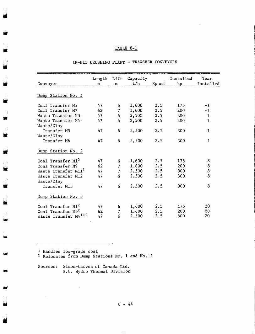
d
d
mcl
d
Y
1
I
TABLE 8-1
IN-PIT CRUSHING PLANT - TRANSFER CONVEYORS
Length Lift Capacity Installed Year Conveyor m m t/h Speed hp Installed
Dump Station No. 1
Coal Transfer M1 Coal Transfer M2 Waste Transfer M3 Waste Transfer M4I Wastelclay
WasteIClay Transfer M5
Transfer M6
Dump Station No. 2
Coal Transfer M12
Waste Transfer MU^ Coal Transfer M9
Waste Transfer M12 Wastelclay Transfer M13
Dump Station No. 3
Coal Transfer M12 Coal Transfer M9' Waste Transfer M4I"
47 62 47 47
47
47
47
47 62
47
47
47 62 47
6
6 7
6
6
6
6 7 7 6
6
6 7 6
1,600 1,600 2,500 2,500
2,500
2,500
1,600 1,600 2,500 2,500
2,500
1,600 1,600 2,500
2.5 2.5 2.5 2.5
2.5
2.5
2.5
2.5 2.5
2.5
2.5
2.5 2.5 2.5
175 200 300 300
300
300
175 200 300 300
300
175 200 300
-1 -1 1 1
1
1
20 20
20
Handles low-grade coal Relocated from Dump Stations No . - 1 and No. 2
Sources: Simon-Carves of Canada Ltd. B.C. Hydro Thermal Division
8 - 44
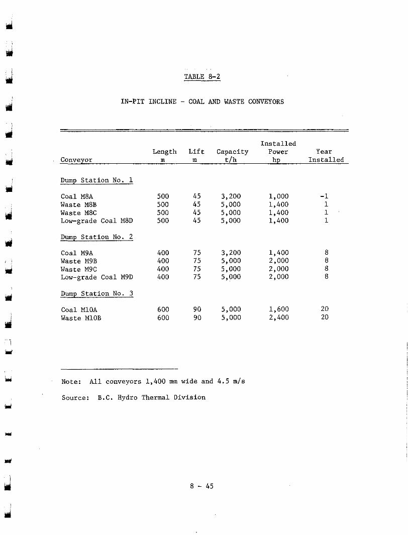
rri
TABLE 8-2
IN-PIT INCLINE: - COAL AND WASTE CONVEYORS
Installed Length Lift Capacity Power 'Year
Conveyor m m t/h hp Installed
Dump Station No. 1
Waste M8B Coal M8A
Waste M8C Low-grade Coal M8D
Dump Station No. 2
Coal M9A
Waste M9C Waste M9B
Low-grade Coal M9D
Dump Station No. 3
Coal MlOA Waste MlOB
500 45 500 45 500 45 500 45
400 75 400 75 400 75 400 75
600 90 600 90
3,200 5,000 5,000 5,000
3,200 5,000 5,000 5 ,000
5,000 5 ,000
1,000 1,400 1,400 1,400
1,400
2,000 2,000
2,000
1,600 2,400
-1 1 1 1
8
8 8
8
20 20
hd Note: All conveyors 1,400 mm wide and 4.5 m/s
Source: B.C. Hydro Thermal Division ri
Y
8 - 45
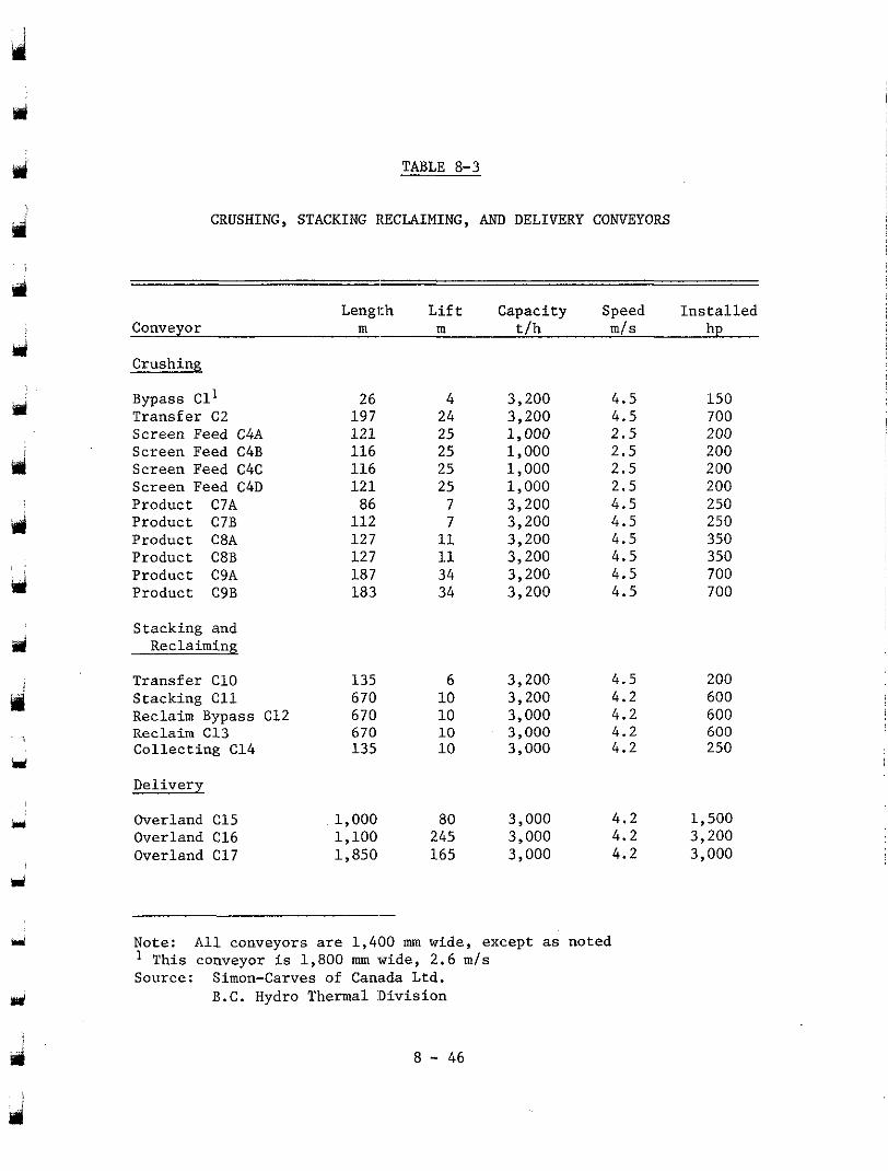
TABLE 8-3
CRUSHING, STACKING IECLAIMING, AND DELIVERY CONVEYORS
Length Lift Capacity Speed Installed Conveyor m m t/h m/s hp
Crushing
Bypass Cl’ Transfer C2 Screen Feed C4A Screen Feed C4B Screen Feed C4C Screen Feed C4D Product C7A Product C7B Product C8A Product C8B Product C9A Product C9B
Stacking and Reclaiming
Transfer C10 Stacking C11 Reclaim Bypass C12 Reclaim C13 Collecting C14
Delivery
Overland C15 Overland C16 Overland C17
26 197 121 116 116 121
112 86
127 127 187 183
135 670 670 670 135
1,000 1,100 1,850
24 4
25 25 25 25 7 7 11 11 34 34
10 6
10 10 10
80 245 165
3,200 4.5
1,000 3,200 4.5
2.5 1,000 2.5 1,000 2.5 1,000 3,200
2.5
3,200 4.5 4.5
3,200 4.5 3,200 4.5 3,200 4.5 3,200 4.5
3,200
3,000 3,200
3,000 3,000
4.5 4.2 4.2 4.2 4.2
3,000 4.2 3,000 4.2 3,000 4.2
Note: All conveyors are 1,400 mm wide, except as noted ’ This conveyor is 1,800 mm wide, 2.6 m/s Source: Simon-Carves of Canada Ltd.
B.C. Hydro Thermal Division
8 - 46
150
200 700
200 200 200 250 250 350 350 700 700
200 600 600 600 250
1,500 3,200 3,000
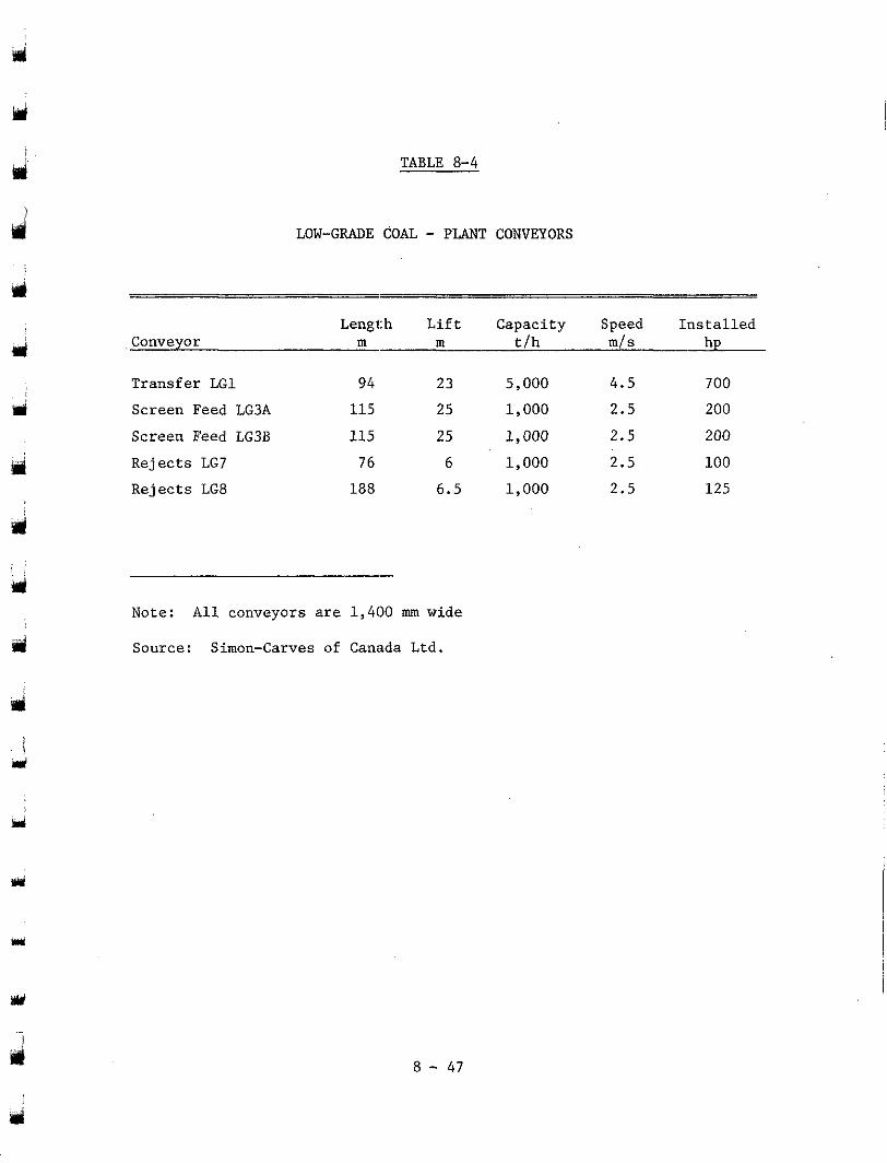
TABLE 8-4
cri
ri
d
LOW-GRADE COAL - PLANT CONVEYORS
Length L i f t Capac i ty Speed I n s t a l l e d Conveyor m m t f h m f s hp
Transfer LG1 94 23 5,000 4.5 700
Screen Feed LG3A 115 25 1,000 2.5 200
Screen Feed LG3B 115 25 I, 000 2.5 200
Rejec ts LG7 76 6 1,000 2.5 100
Rejects LG8 188 6.5 1,000 2.5 125
Note: A l l conveyors are 1,400 mm wide
Source: Simon-Carves of Canada Ltd.
8 - 47
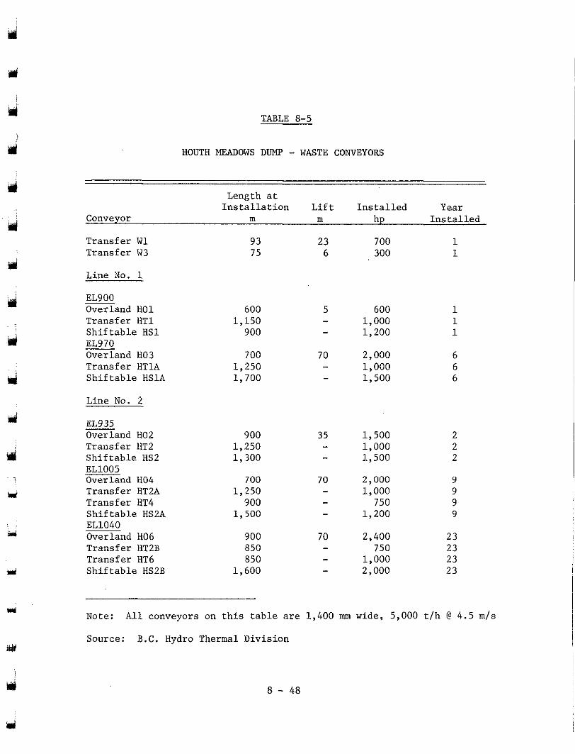
TABLE 8-5
HOUTH MEADOWS DUMP - WASTE CONVEYORS
J
d
Y
Isi 1
Y
d
r'
Length at Installation Lift Installed Year
Conveyor m m hp Installed
Transfer W1 Transfer W3
Line No. 1
EL900 Overland H01 Transfer HT1 Shiftable HS1 EL970 Overland H03 Transfer HTlA Shiftable HSlA
Line No. 2
EL935 Overland H02 Transfer HT2 Shiftable HS2 EL1005 Overland H04 Transfer HT2A Transfer HT4 Shiftable HS2A EL1040 Overland H06 Transfer HT2B Transfer HT6 Shiftable HS2B
93 75
600 1, :I50 900
700 1,250 1, '700
900 1,250 1,300
700 1,250 900
l,.500
900 850 850
1,600
700 1 300 1
600 1,000 1,200
2,000 1,000 1.500
1,500 2 1,000 2 1,500 2
2,000 9 1,000 9 750 9
1,200 9
2,400 23 750 23
1,000 23 2,000 23
Note: All conveyors on this table are 1,400 mm wide, 5,000 t/h @ 4 . 5 m/s
Source: B.C. Hydro Thermal :Division
8 - 48
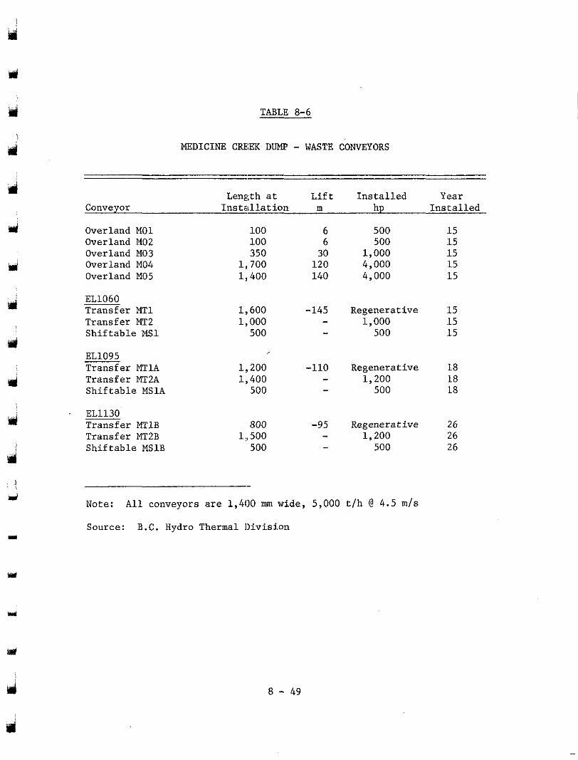
TABLE 8-6
iil
MEDICINE CREiEK DUMP - WASTE CONVEYORS
Length at Lift Installed Year Conveyor Installation m hp Installed
Overland M01 Overland 1402 Overland M03 Overland M04 Overland M05
EL1060 Transfer XT1 Transfer MT2 Shiftable MS1
EL1095 Transfer MTlA Transfer MT2A Shiftable MSlA
. EL1130 Transfer MTlB Transfer MT2B Shiftable MSlB
100 6 500 :15 100 350
6 500 :L 5 30
1,700 1,000
120 115
4,000 1,400 140 4,000 :15
:15
1,600 -145 Regenerative 1,000
:15 - 1,000 .15 500 - 500 .15
1 !I 200 -110 Regenerative 18 1,. 400 - 1,200 18 - 500 18 500
800 -95 Regenerative 26 1 :, 500 - 1,200 26 500 - 500 26
Note: All conveyors are 1,400 mm wide, 5,000 t/h (3 4.5 m/s
Source: B.C. Hydro Thermal Division
Y
8 - 49
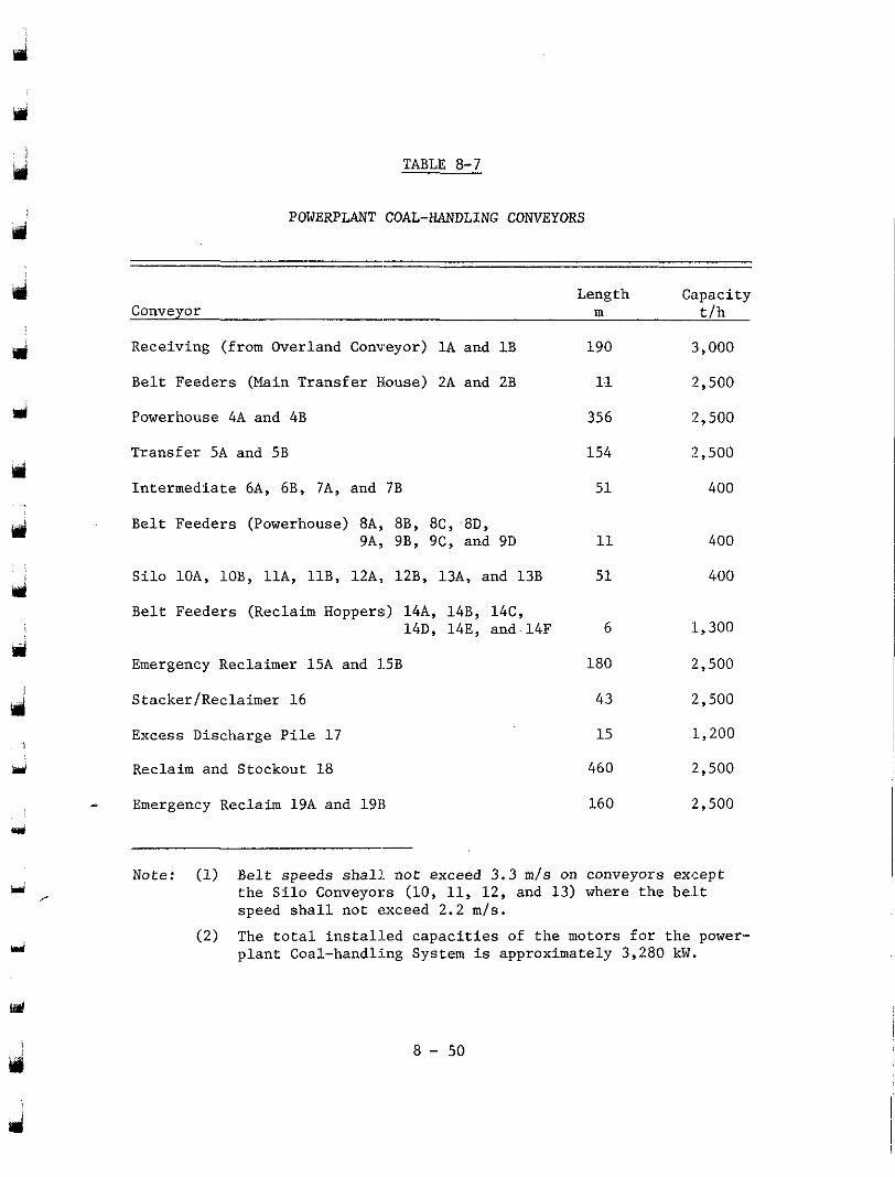
TABLE 8-7
d POWERPLANT COAL-HANDLING CONVEYORS
Length Capacity Conveyor
Receiving (from Overland Conveyor) lA and 1B 190 3,000
Belt Feeders (Main Transfer House) 2A and 2B 11 2,500
m t/h
w
rl Powerhouse 4A and 4B 356 2,500
Transfer 5A and 5B
Intermediate 6A, 6B, 7A, and 7B
154 :? ,500
51 400
Belt Feeders (Powerhouse) 8A, 8B, 8C, 8D, 9A, 9B, 9C, and 9D 11 400
Silo lOA, 10B, 11A, 11B, 12A, 12B, 13A, and 13B 51 400
Belt Feeders (Reclaim Hoppers) 14A, 14B, 14C, 14D, 14E, and.l4F 6
d :L ,300
Emergency Reclaimer 15A and 1.5B 180 :? ,500
4 Stacker/Reclaimer 16 43 :2,500
1 Excess Discharge Pile 17 15 1,200
ad Reclaim and Stockout 18 460 :2,500
- Emergency Reclaim 19A and 19B 160 :2,500 r
iri Note: (1) Belt speeds shall not exceed 3.3 m/s on conveyors except
,. the Silo Conveyors (10, 11, 12, and 13) where the be.lt speed shall not exceed 2 . 2 m/s.
u (2 ) The total installed capacities of the motors for the power- plant Coal-handling System is approximately 3,280 kW.
8 - 50
d
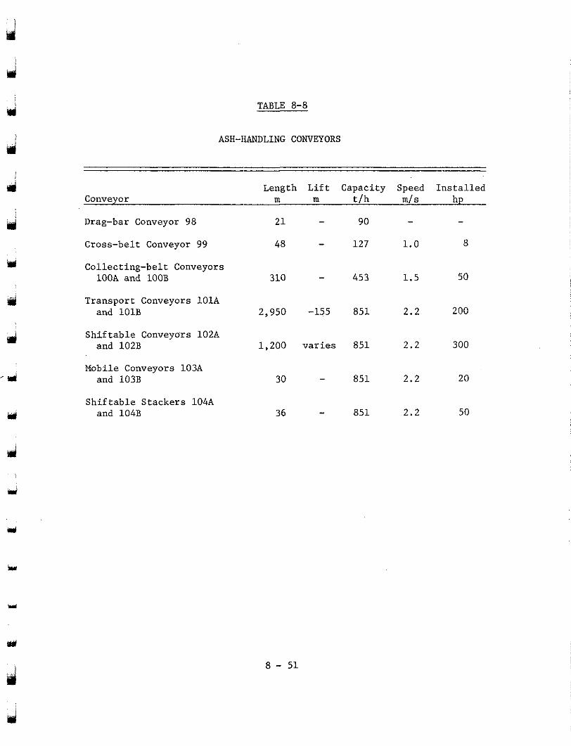
1
TABLE 8-8
rri I ASH-HANDLING CONVEYORS
i
j
Y
Length Lift Capacity Speed Installed Conveyor m m t/h m l s hp
Drag-bar Conveyor 98
Cross-belt Conveyor 99
21 - 90 -
48 - 127 1.0 8
-
Collecting-belt Conveyors lOOA and lOOB 310 - 453 1.5 50
Transport Conveyors lOlA and lOlB 2,950 -155 851 2.2 200
Shiftable Conveyors 102A and 102B 1,200 varies 851 2.2 300
Mobile Conveyors 103A and 103B 30 - 851 2.2 20
Shiftable Stackers 104A and 104B 36 - 851 2.2 50
3
8 - 51
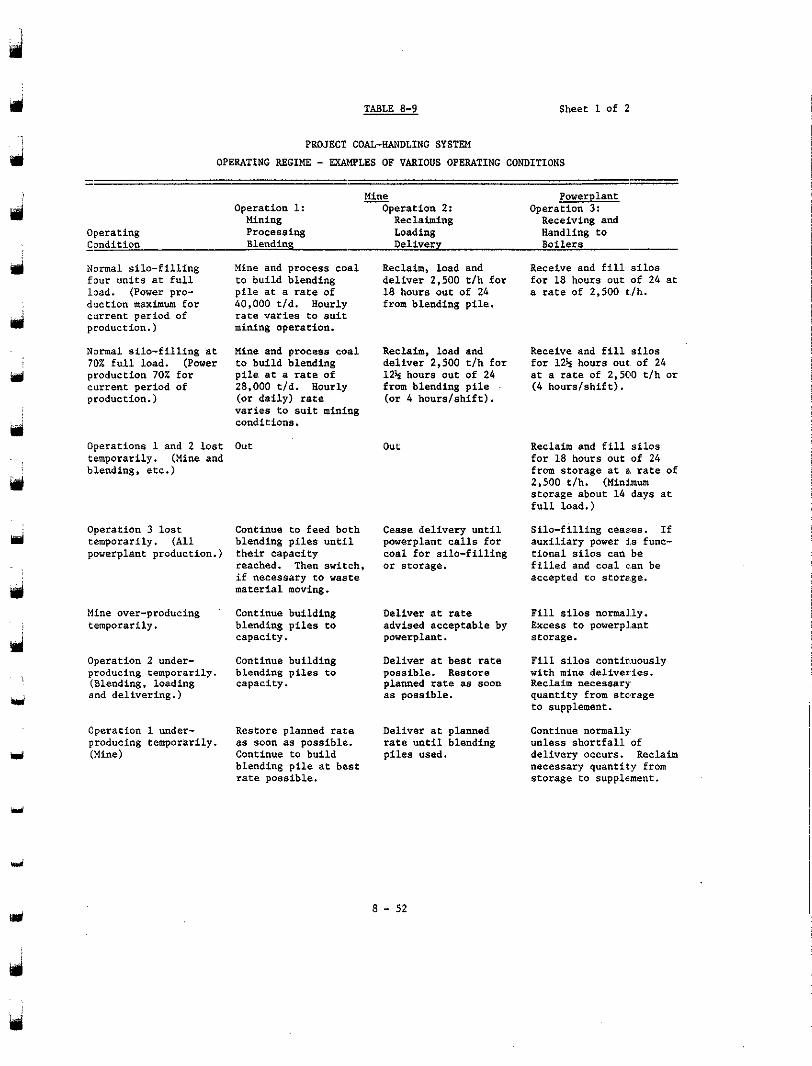
TABLE 8-9 Sheet 1 of 2
PROJECT COAL-HANDLING SYSTEM OPERATING REGIME - EXAHPLES OF VARIOUS OPERATING CONDITIONS
Operating - Condition Normal silo-filling four units at full load. (Power pro- duction maximum for current period of production.)
Normal silo-filling at 70% full load. (Power production 70L for current period of production.)
Operations 1 and 2 lost temporarily. (Mine and blending, etc.)
m Operation 3 lost
powerplant production.) temporarily. (All
Mine over-producing temporarily.
Operation 2 under- producing temporarily.
and delivering.) (Blending, loading
Cperation 1 under- producing temporarily. (Mine)
Mine Operation 1:
- Mining Processing Loading Blending Delivery
Operation 2: Reclaiming
Mine and process coal Reclaim, load and
pile at a rate of to build blending deliver 2,500 tlh for
40,000 tld. Hourly 18 hours out of 24 from blending pile.
rate varies to suit mining operation.
Mine and process coal Reclaim, load and to build blending deliver 2,500 t/h for pile at a rate of 124 hours out of 24 28,000 t/d. Hourly from blending pile
varies to suit mining (or daily) rate (or 4 hourslshift).
conditione.
out out
Continue to feed both blending piles until their capacity reached. Then switch, if necessary to waste material moving.
Continue building blending piles to capacity.
Continue building blending p i l e s to capacity.
Restore planned rate 8s soon as possible.. Continue to build blending pile at be.st rate possible.
Cease delivery until powerplant calls for coal for silo-filling or storage.
Deliver at rate advised acceptable by powerplant.
Deliver at best rate possible. Restore planned rate as soon as possible.
Deliver at planned rate until blending piles used.
Operation 3: Powerplant
Receiving and Handling to Boilers
Receive and fill silos for 18 hours out of 24 at a rate of 2.500 t./h.
Receive and fill silos for 124 hours out. of 24 at a rate of 2,500 tlh or ( 4 hourslshift).
Reclaim and fill silos far 18 hours out of 24 from storage at a rate of 2,500 t/h. (Minimum storage about 14 days at full load.)
Silo-filling ceases. If auxiliary power i.8 func- tional silos can be filled and coal ean be accepted to storage.
Fill silos normal.1~. Excess to powerp1.ant storage.
Fill silos continuously with mine deliveries. Reclaim necessary quantity from storage to supplement.
Continue normally unless shortfall of delivery occurs. Reclaim necessary quantity from storage to supplement.
8 - 52
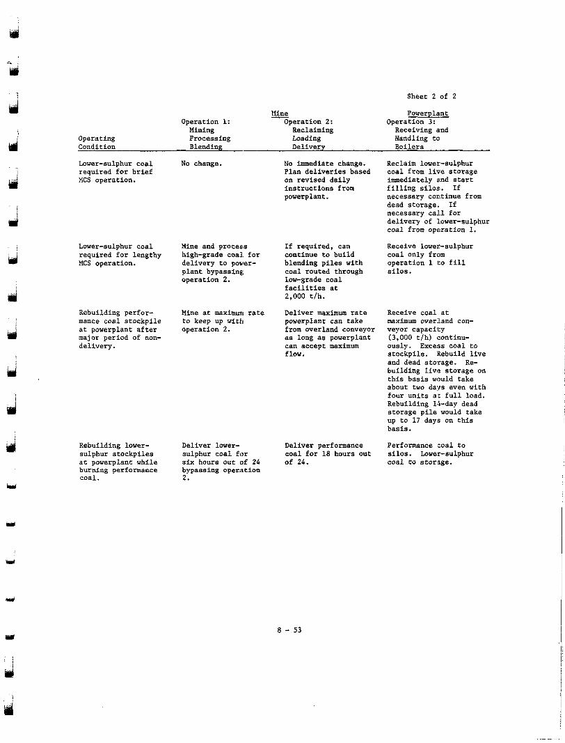
d
Sheet 2 of 2
Powerplant
Receiving and Handling to Boilers
Operation 3:
Reclaim lower-sulphur coal from live storage
filling silos. If immediately and start
necessary continue from dead storage. If necessary ca l l for delivery of lower-sulphur coal from operation 1.
Receive lower-sulphur coal only from operation 1 to fill silos.
i
d
Operating Condition
Lower-sulphur coal
HCS operation. required for brief
Lower-sulphur coal
MCS operation. required for lengthy
Rebuilding perfor- mance coal stockpile at powerplant after major period of non- delivery.
Rebuilding lower- sulphur stockpiles ac powerplant while burning performance coal.
Operacion 1: Mining Processing Blending
No change.
Mine and process high-grade coal. for delivery t o power-
operation 2. plant bypassing
Nine ac maximum rate t o keep up with operation 2.
Deliver laver-
six hours out (of 24 sulphur coal for
bypassing oper~tion 2 .
Mine - Operation 2: Reclaiming Loading Delivery
No imediata change. Plan deliveries based on revised daily
powerplant. instructions from
continue to build If required, can
blending piles with coal routed through low-Erade coal
~
facilities st 2,000 tlh.
Deliver maximum rate powerplant can take from overland conveyor as long as powerplant can accept maximum flow.
Deliver performance coal for 18 hours out of 24.
maximum overland con- Receive coal at
veyor capacity (3.000 tlh) <:ontinu- ously. Excelis coal to
and dead storage. Re- stockpile. Rebuild live
building Iivtt storage on
about two days even with this basis would take
four units a t full load. Rebuilding 14-day dead
up to 17 day3 on this storage pile would take
basis.
Performance mal t o silos. Lower-sulphur coal to storage.
8 - 53
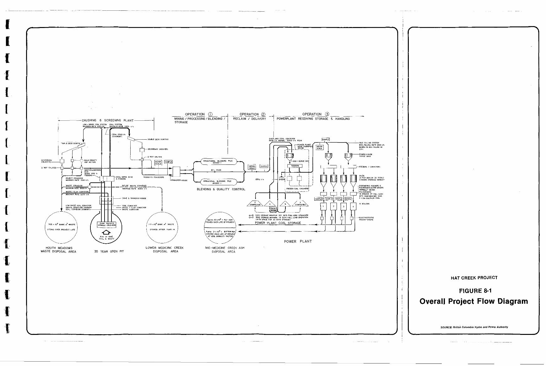
c
WASTE DISPOSAL AREA H O U T H M E A D O W S
35 YEAR OPEN PIT LOWER MEDICINE CREEK
DISPOSAL AREA
HAT CREEK PROJECT
FIGURE 8-1
Overall Project Flow Diagram
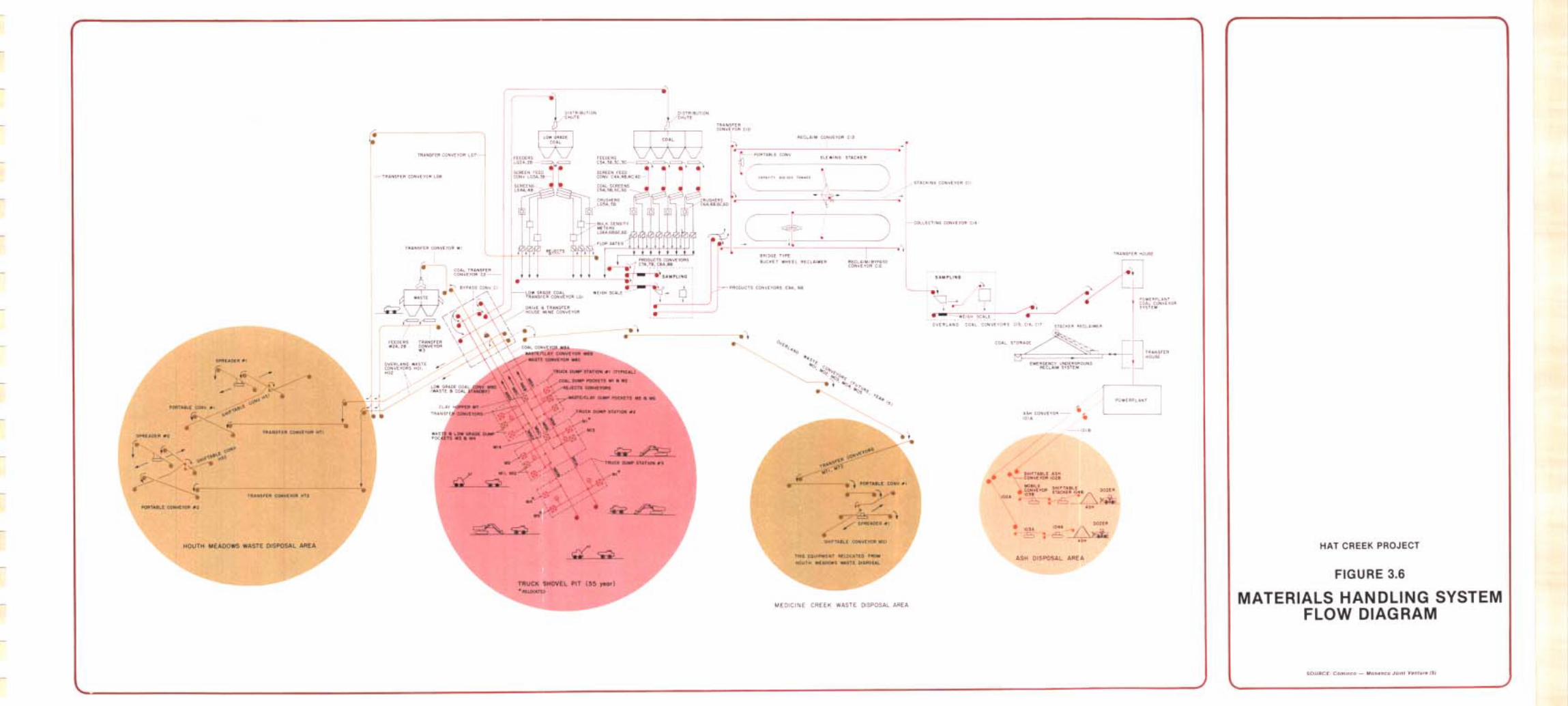
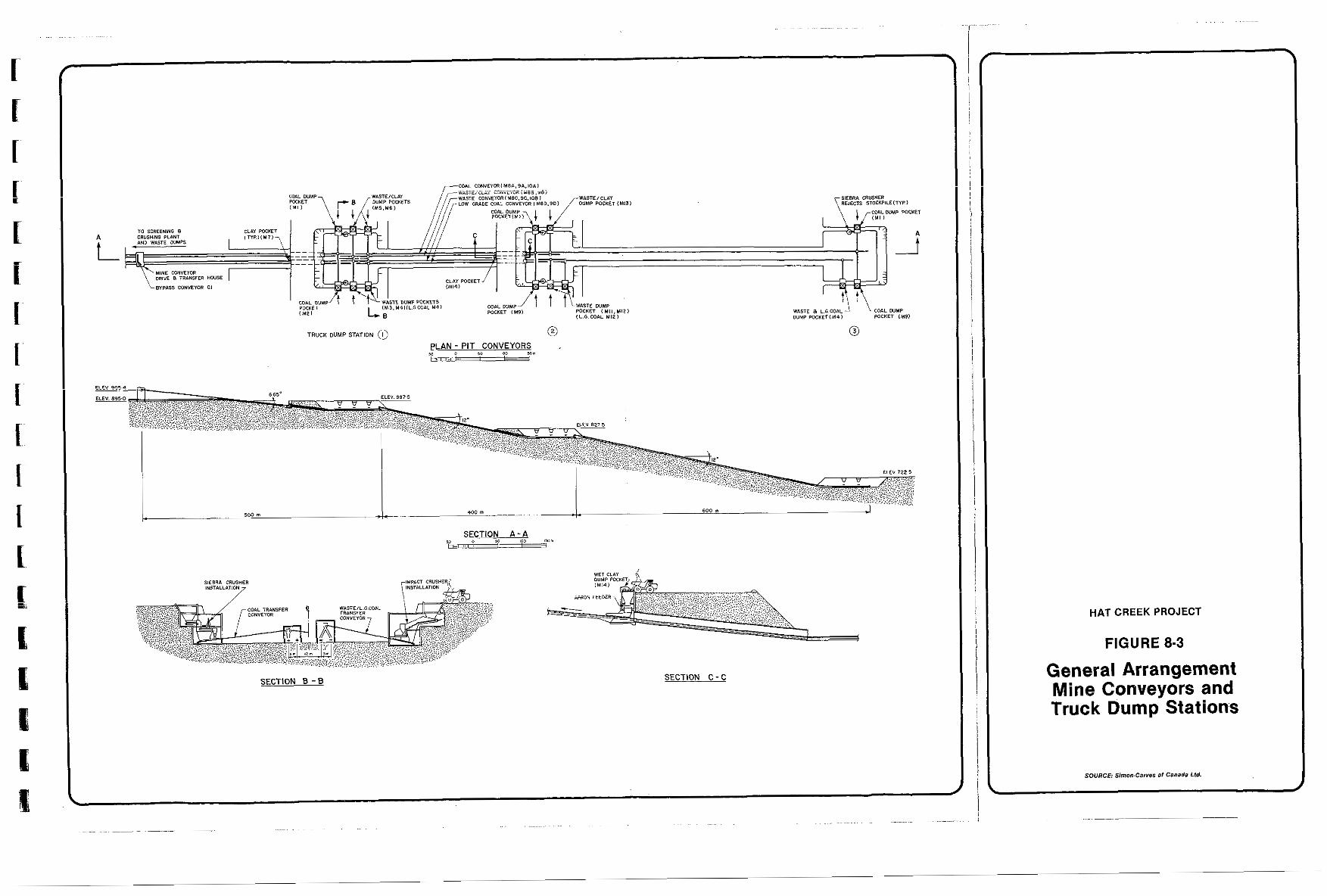
TRUCK DUMP STATION 0 0 Io 0 $0 800 ,am PLAN - PIT CONVEYORS 1" I
SECTION 8 - 8 SECTION C - C
HAT CREEK PROJECT
FIGURE 8-3
General Arrangement Mine Conveyors and Truck Dump Stations
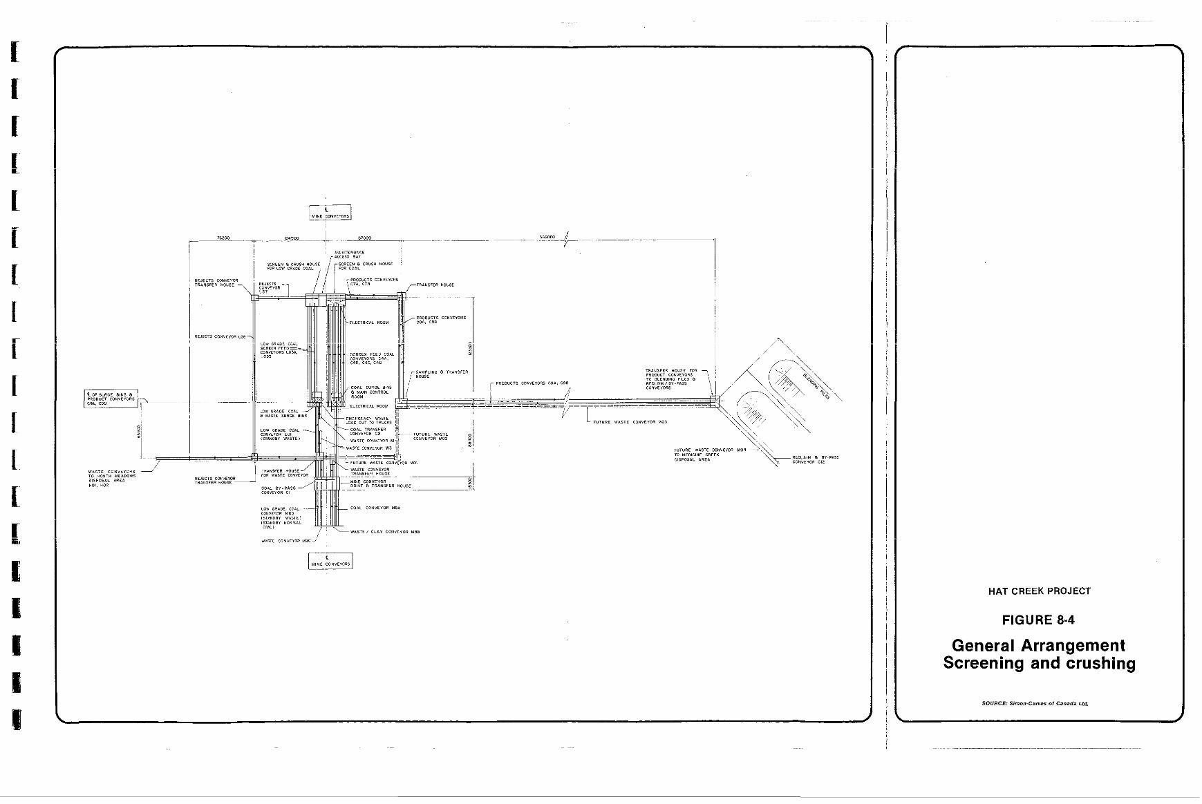
r
81 ::!
HAT CREEK PROJECT
FIGURE 8-4
General Arrangement Screening and crushing
SOURCE: Simon-Carver of Canada Ltd.
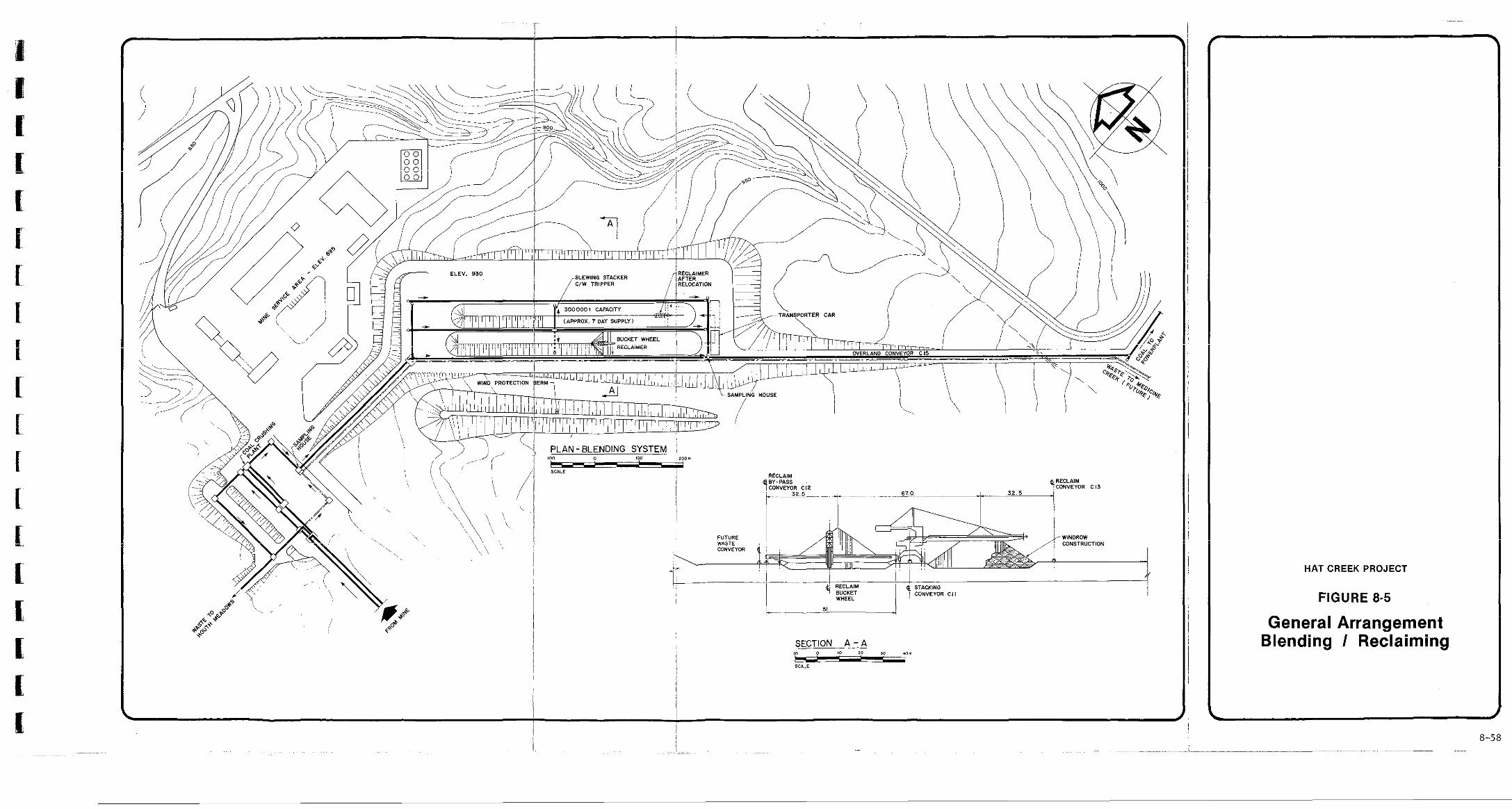
~
CONSTRUCTION
I
4 z:; STACKING CONVEYOR C I I
WHEEL
SECTION A - A
"*- SCilLE
HAT CREEK PROJECT
FIGURE 8-5
General Arrangement Blending I Reclaiming
t d
8-58
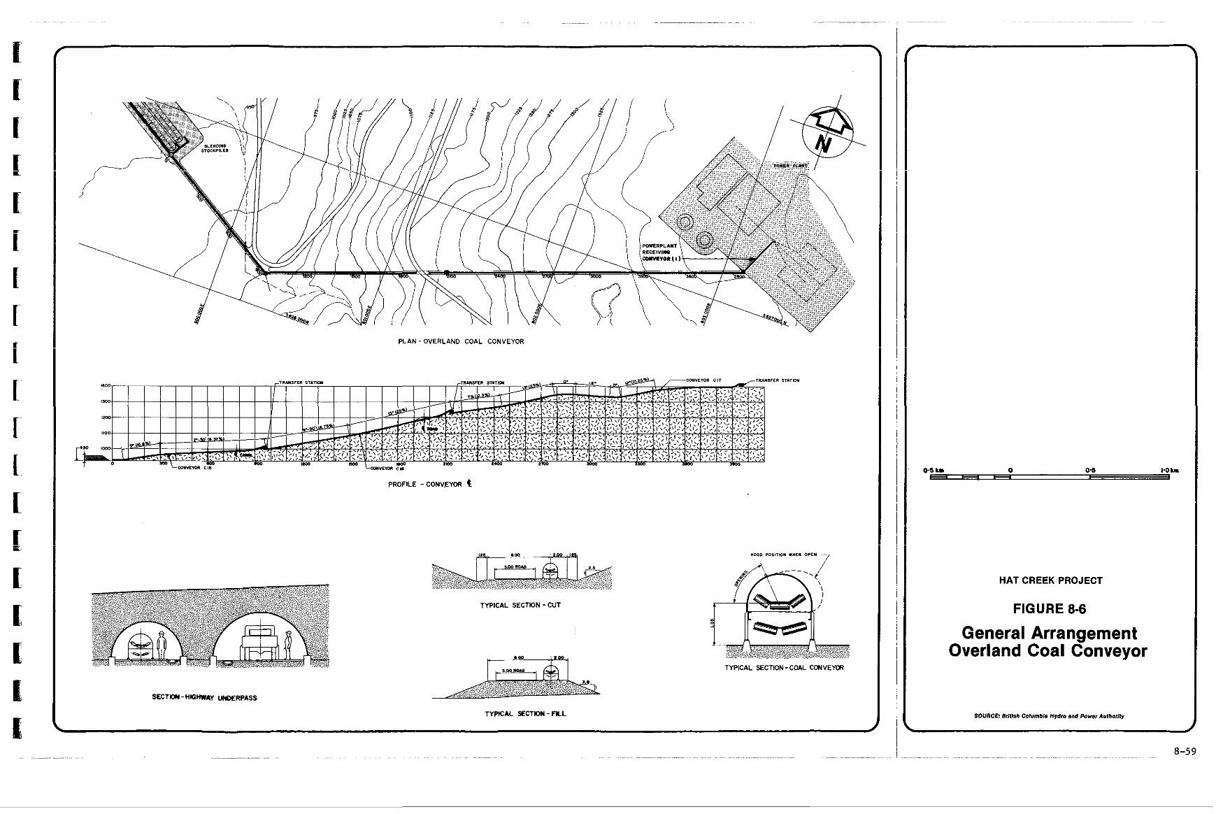
~ ~ ~ .... ~. .. ... ... . .. ~
PLAN-OVERLAND COAL CONVEYOR
PROFILE - CONV.EYOR
TYPICAL SECTION - CUl
0.m : 100
TYPICAL S C T W - FILL
.
HAT CREEK PROJECT
FIGURE 8-6
General Arrangement Overland Coal Conveyor
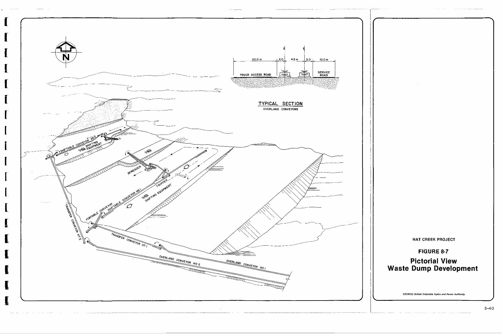
.
HAT CREEK PROJECT
FIGURE 8-7
Pictorial View Waste Dump Development
SOURCE: British Columbia Hydro and Power Authority
d
8-60
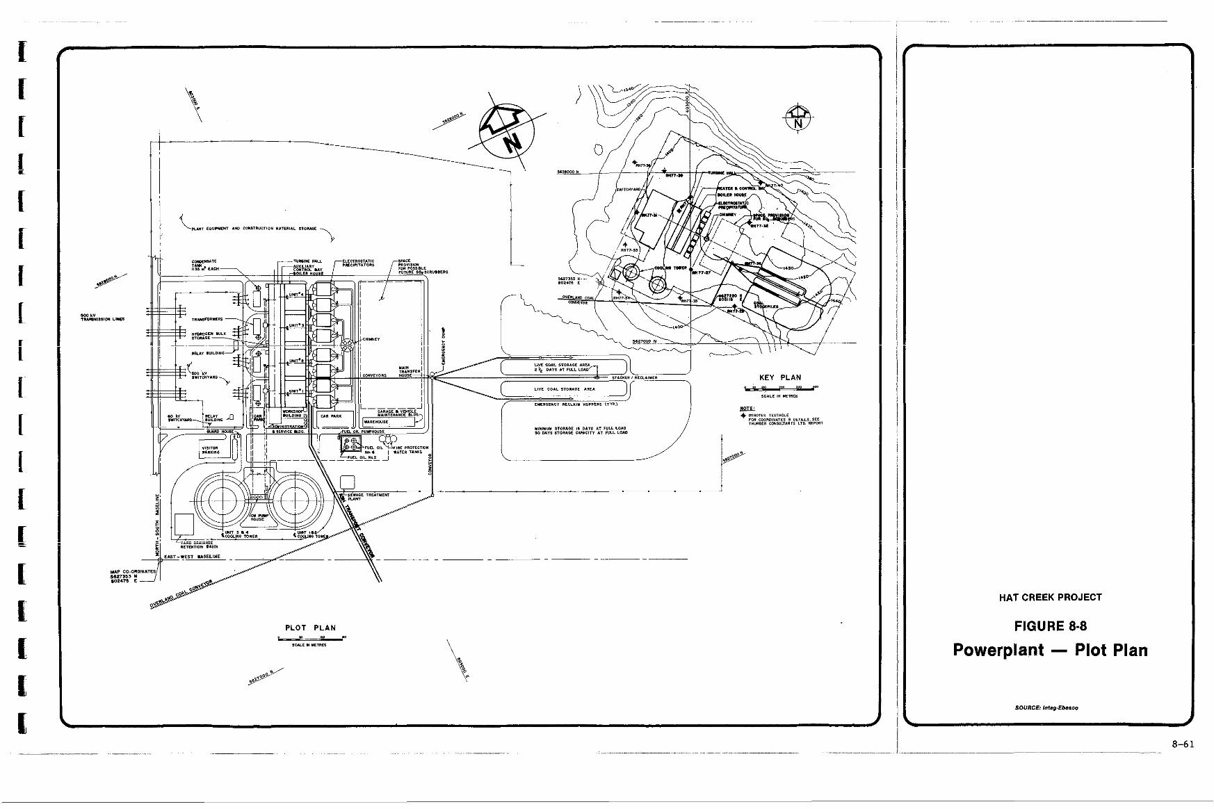
. . . .. .. ~"
HATCREEKPROJECT
FIGURE 8-8
Powerplant - Plot Plan
SOURCE: InIag.Ebass0
I d
8-6 1
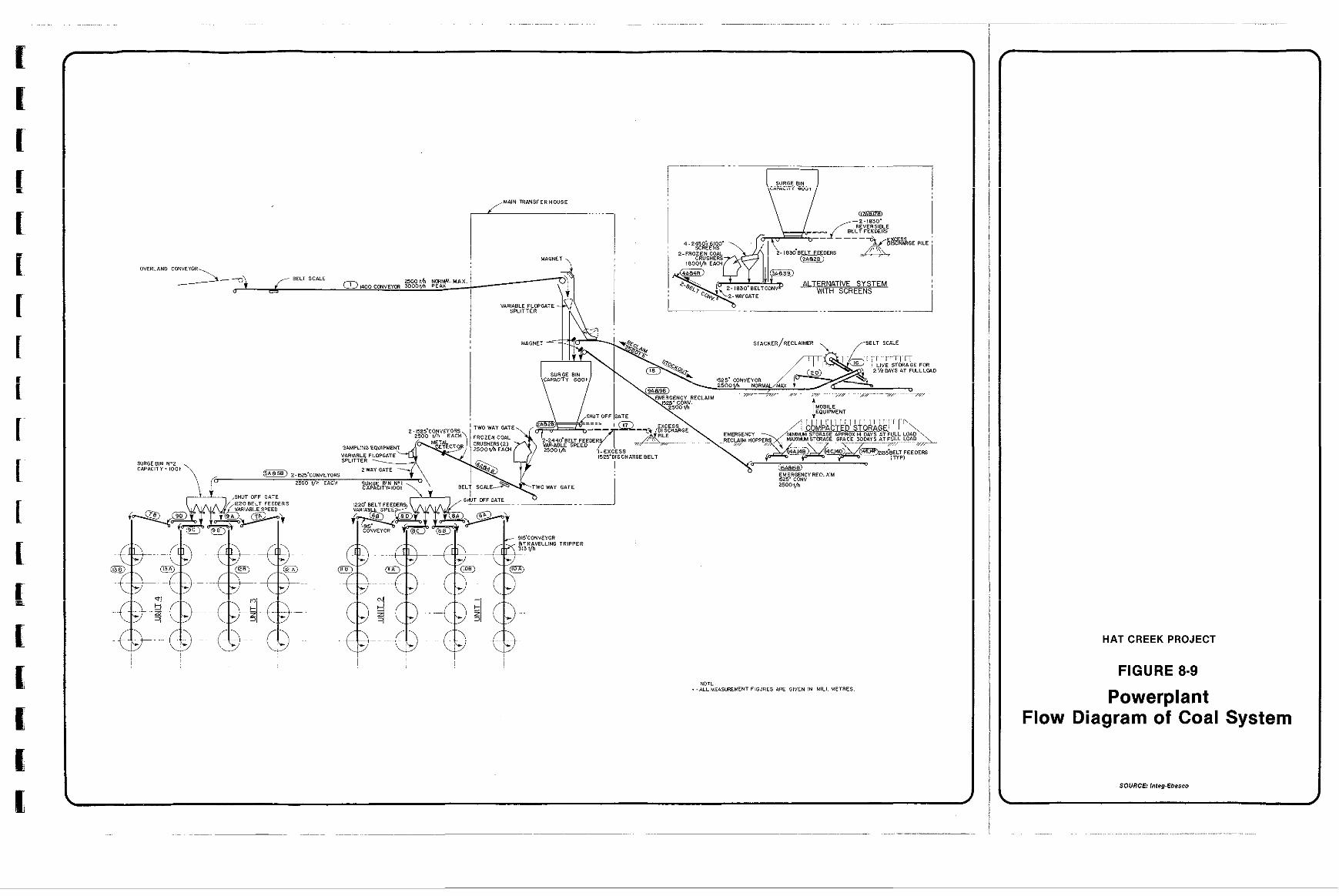
t I
M&IONET ,
HAT CREEK PROJECT
FIGURE 8-9
Powerplant Flow Diagram of Coa . I System
SOURCE: Inlsg-Ebasco
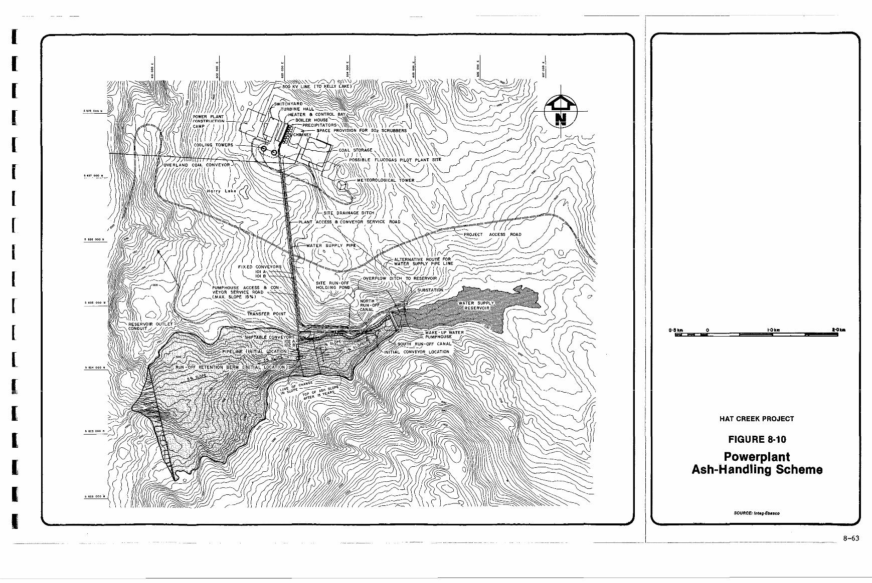
Hi "i H
HAT CREEK PROJECT
FIGURE 8-10
Powerplant Ash-Handling Scheme
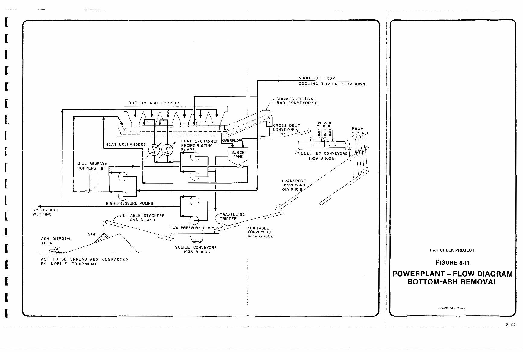
TO FLY ASH WETTING
c"
BOTTOM ASH HOPPERS
A
HEAT EXCHANGERS RECIRCULATING
MILL REJECTS HOPPERS (8)
I 4 - I
HIGH PRESSURE PUMPS
- M A K E - U P F R O M - C O O L I N G T O W E R B L O W D O W N
f SUBMERGED DRAG BAR CONVEYOR 98
/ IiM TRANSPORT CONVEYORS
SHIFTABLE STACKERS
SHIFTABLE CONVEYORS iO2A 8 1028;
ASH DISPOSAL AREA
ASH TO BE SPREAD AND COMPACTED BY MOBILE EQUIPMENT.
MOBILE CONVEYORS 103A 81 1038
d
HAT CREEK PROJECT
FIGURE 8-11
POWERPLANT - FLOW DIAGRAM BOTTOM-ASH REMOVAL
SOURCE: IntepEbasco . d
8-64
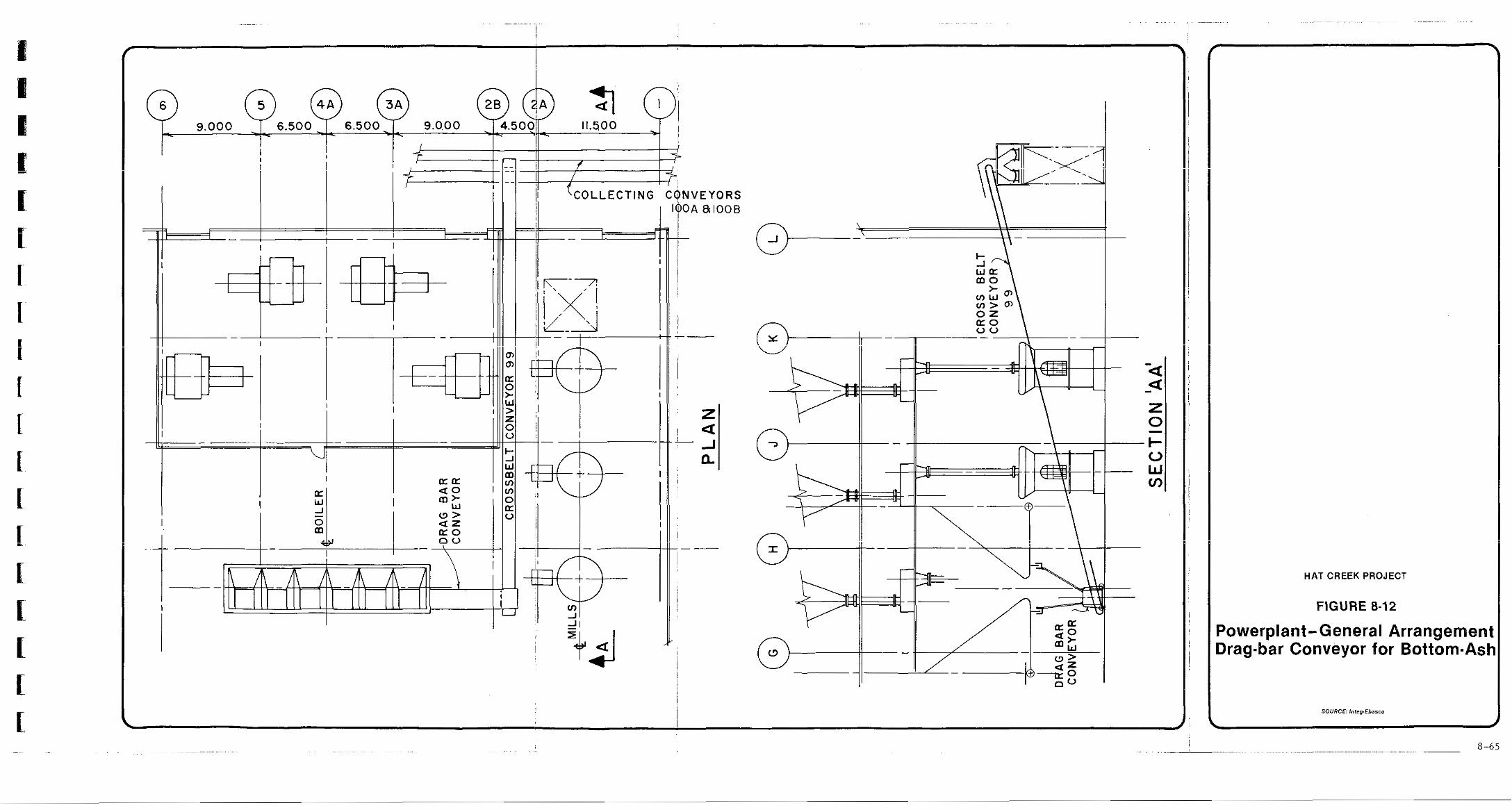
. ,.. . ..... . .
HAT CREEK PROJECT
FIGURE 8-12
Powerplant-General Arrangement Drag-bar Conveyor for Bottom-Ask
SOURCE: InlegIbasco
~ ~ ~ .. 8-65
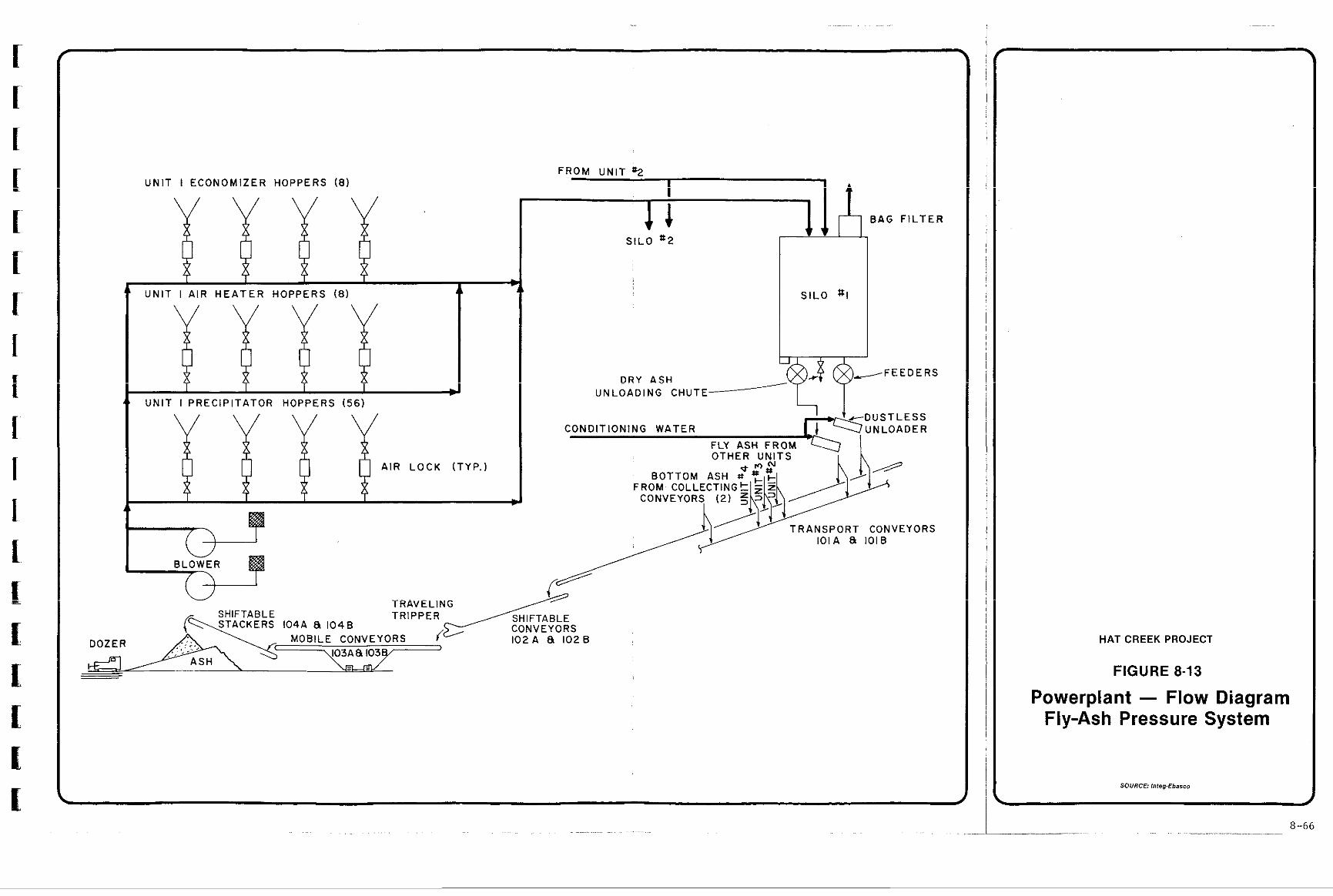
~~ . . ~~ .
f
I[
I r U N I T I E C O N O M I Z E R H O P P E R S ( 8 )
c C# 1' I i I I
F R O M U N I T ' 2 I
L I
l i 111, B A G F I L T E R
S I L O s-2
- c ' U N I T I A I R H E A T E R H O P P E R S ( 8 ) 1 L L S I L O SI
- F E E D E R S
U N L O A D I N G C H U T E
C O N D I T I O N I N G W A T E R
FLY ASH FROM
A I R L O C K ( T Y P . )
I r Qc
11 i t t \ J
101A 8 l O l B
TRAVELING
CONVEYORS 1 0 2 A 8 1026
~ . . . . . . ~~ ~ ~~~~~ ~ ~ ~ .~~ ~ ..
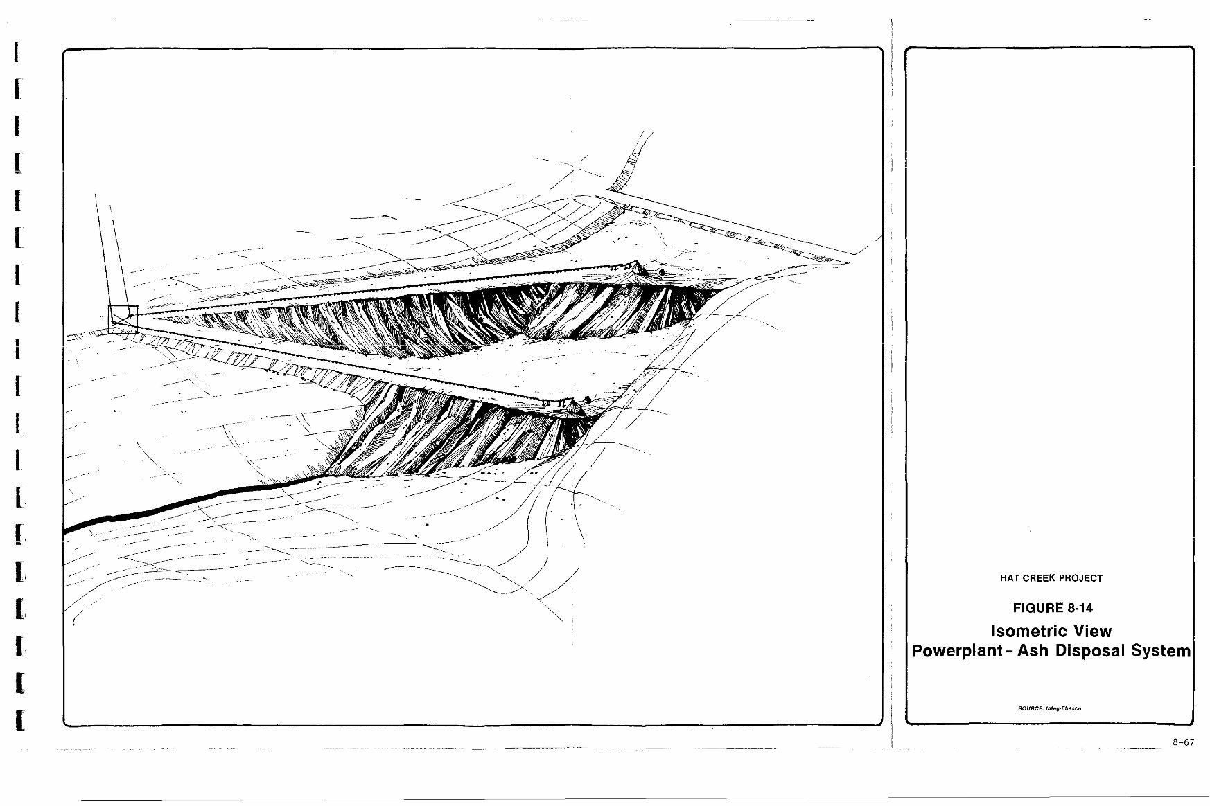
J
HAT CREEK PROJECT
FIGURE 8-14
Isometric View Powerplant - Ash Disposal System
SOURCE: Inleg-Ebasco
i
d
i
Y
9 EQUIPMENT
9.1 Production Equipment 9.1.1 Coal Mining 9.1.2 Waste Removal 9.1.3 Operation at Maximum Capacity Rating
9.2 Support Equipment 9.2.1 Road Construction and Maintenance 9.2.2 Mine Support 9.2.3 Material-handling Support 9.2.4 Service Equipment
1 2 3 5
7 7 8 10 11
iri i
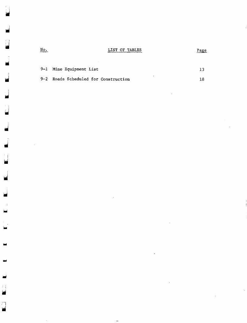
pr
d
m
. .
d
Y
3
- No. LIST OF TABLES
9-1 Mine Equipment List
9-2 Roads Scheduled f o r Construction
d
SECTION 9
EQUIPMENT SELECTION
d
d
d
d : ! . .
Y
3
i
that will be used in the development and operation of the mine. The This section discusses the selection of the equipment
initial equipment is scheduled to become operational in Year -2 to commence pre-production development.
For the purposes of this study it has been assumed that any earth-moving required outside the limits of the pit for site prepa- ration and construction purposes would be performed by contractors' equipment. The costs of this work have been provided in the construction capital cost estimates. This work could be reassigned to the mine crew and equipment with a minor revision of the schedule.
duction equipment for loading and hauling coal and waste; and support The mining equipment'is divided into two groups: pro-
equipment to execute the numerous other tasks required for the continuous, efficient operation of the mine.
9.1 PRODUCTION EQUIPMENT
A preliminary evaluation of possible mining equipment was conducted to determine its suitability for the proposed methods of operation. The equipment that passed this Initial screening was sub- jected to a detailed cost and productivity analysis in the context of the mine plan and schedule.
sidering the shovels and trucks as a system for three critical mining periods:
(1) Year 6 - utilization of first dump pocket only; first high pro-
The cost and productivity analysis was performed con-
duction period;
(2 ) Year 9 - utilization of first and second dump pockets; multiple mining areas;
9 - 1
J
d . .
(3) Year 2 1 - u t i l i z a t i o n of f i r s t , second, and third dump pockets; high coal production from lower benches.
with uphi l l , downhil l , and ].eve1 hauls . For each year, haul road These t ime periods include both long and s h o r t d k t a n c e s
p r o f i l e s were developed and truck travel times calculated. Fixed cycle times were developed for eac:h shovel-truck combination. On l e v e l h a u l s , t rucks were l i m i t e d t o a maximum speed of 40 km/h. On downhill hauls the speed limits were establ- ished to provide maximum braking capabi l i ty .
si 9.1 .1 Coal Mining
1 i
isi
' Y
: Y
Y
m
1. Shovels
The s e l e c t i o n of the coa l shovel is d i c t a t e d by t h e dec is ion to adopt selective mining methods. The most e f f ec t ive shove l fo r t h i s pu rpose i s the hydraulic excavator. Because of the va : r iab i l i ty of t he depos i t , t he more shove l s ava i l ab le fo r ope ra t ion , t he ea s i e r i t is t o maintain a cons i s t en t qua l i t y of output . The need to p rovide f l e x i b i l i t y f o r q u a l i t y c o n t : r o l and to permit effective parting:; removal a t 2 m was balanced against the economics of u s ing l a rge r equipment. The machine se l ec t ed fo r l oad ing coa l is a hydraul ic shovel w i t h a 10.7 m3 bottom-dump bucket equivalent to the Poclain 1000.
shovels have been assigned a quan t i ty of waste pa r t ings and low-grade c o a l t o b e removed each year equivalent to 20% of the coal tonnage.
In add i t ion t:o the scheduled coal product ion, these
Over t h e p r o j e c t l i f e , between two and th ree shove l s a r e capable of loading the ass igned quant i t ies of c o a l and pa r t ing ma te r i a l s . To provide the necessary f lex ib i l i ty for p roducing a uniform qual i ty of coa l , and t o accommodate ext:ended per iods of powerplan t opera t ion a t maximum capacity, four e1ect:rically-powered hydraulic shovels w:tl l be operat ional , except during t:he i n i t i a l bu i ldup t o fu l l p roduc t ion and a t a i l i ng -o f f pe r iod i n t he latter years of t he p ro j ec t .
as many as 15 benches . Durhg th i s per iod , a f i f t h s h o v e l has been provided for to reduce the impact of numerous shovel moves. Th:Ls
with a backhoe attachment as: well as the s tandard shovel f ron t . This addi t iona l shovel would be a diesel-powered u n i t and would be suppl ied
uni t p rovides mobi l i ty and f l e x i b i l i t y t o t h e o p e r a t i o n . The backhoe
In the peak production years, coal will be mined from
a ,
i i 9 - 2
attachment w i l l a l s o b e u s e f u l i n e x c a v a t i n g s i n k i n g c u t s and a s s i s t i n g i n s e l e c t i v e mining.
2. Trucks
Three s izes of d iese l -e lec t r ic haulage t rucks were eva lua ted opera t ing in conjunct ion wi th the 10.7 m3 hydraul ic shovel . These trucks were r a t e d a t 77 t , 91 t , and 109 t.
The economic a n a l y s i s performed fo r t he t h ree s e : l ec t ed c r i t i c a l p e r i o d s showed a marginal cost advantage for the 77-t .truck over the 91-t t ruck, with the 109-t t ruck ranked third. I n rev:fewing t h e f lee t s i ze deve loped i n t he ana lys i s , a be t t e r ba l ance of t r u c k s t o
most su i t ab le coa l t ruck . shovels was obtained with the 77-t trucks, which were confirmed as t h e
t rucks required ranges from n i n e t o 11. The p r i n c i p a l s p e c i f i c a t i o n s of t h e t r u c k are: 77 m3 c o a l box; 1,000 hp engine; 24.00 x 49 tirlls, and a 23 : l gea r r a t io .
During the peak production years the number of 7 7 - t
9.1.2 Waste Removal,
moved: consolidated and unconsolidated. The conso l ida t ed ma te r i a l s a r e t y p i f i e d by the c l ays tones and s i l t s t o n e s of the Medicine Creek and Coldwater formations. Glacial till, and the sands and grave ls ,on t h e East s i d e of t h e p i t are c l a s s i f i e d as unconsolidated materials, along w i t h l a r g e q u a n t i t i e s of b e n t o n i t i c s l i d e material on t h e West s ide .
There are two pr inc ipa l types of waste materials t o b e
1. Shovels
mined present very different problems. The consolidated waste is a The two d i f f e r e n t c a t e g o r i e s of waste material to be
sa tu ra t ed , so f t , cohes ive ma te r i a l , which, when frozen, will form a
period. When b la s t ed , f rozen c l ay b reaks i n to chunky p i e c e s t h a t a r e rock- l ike c rus t a metre o r more deep during an extended cold weather
not compatible with conveyor transportation. An a l t e rna t ive approach t o b l a s t ing t he c l ays tones and s i l t s t o n e s would be t o b l a s t t h e m a t e r i a l p r io r t o f r eez ing , u s ing c r a t e r b l a s t ing t echn iques , a method t ' ha t has proven e f fec t ive in tar sands. However, because of the high moisture content of t he c l ays , t he e f f ec t iveness of this approach i s quest ionable u n t i l o p e r a t i o n a l t e s t i n g c a n b e done.
9 - 3
!
mi
ui
ul
d
bld
I
i
13
mi
!
Because of the nature of the claystones, it was c:oncluded that the most effective method of excavating this material would be to use hydraulic shovels. A Demag 241 with a 14.5 m3 bucket is the only production unit in this size range currently available.
of a D-9 ripper to handle the frozen toe. Special attention will also be required in operational planning to maintain continuous operation during the Winter months to prevent the face freezing. It will also be necessary to prevent traffic travelling on top of material to be mined during the Winter, because of the greater depth of the frozen layer that this causes.
The application of this unit would require the assistance
The unconsolidated materials present less serious excavating problems. This material can be excavated with either a standard mining cable shovel or a hydraulic shovel. A cost and productivity analysis was conducted to compare a 16.8 m3 cable shovel with the 14.5 m;' hydraulic shovel. The results showed marginal cost savings using the 16.8 m3 shovel for loading unconsolidated waste. The study also demonstrated that additional equipment scheduling problems would be introduced with a mixed shovel fleet, causing an increase in the number and length of shovel moves. The hydraulic shovels have the additional advantages of being lighter in weight, exerting less ground-bearing pressure, and capable of travelling approximately twice as fast as the cable shovels.
of the cable shovel and resulted in the 14.5 m hydraulic shovel. being selected for loading both the consolidated and unconsolidated waste materials.
These factors outweigh the insi nificant cost savings .$
2 . Trucks
Three sizes of diesel-electric haulage trucks bei.ng loaded by 14.5 m3 hydraulic shovels were evaluated for waste haulage. These trucks were 109 t, 136 t, and 154 t. Other truck sizes were eliminated in a preliminary evaluation.
critical periods identified above. The 154-t truck showed the ].owest unit production costs and was selected for waste haulage. The principal specifications for the truck are: 90 m3 rock box; 1,600 hp engine; 36.00 x 51 tires, and a 28.85:l gear ratio.
The economic analysis was performed using the same three
Consideration was given to standardizing trucks for coal and waste, but the requirements for selective mining of coal dic:tate a smaller unit than is economically justified for moving larger quantities of waste over significantly different haul road profiles.
9 - 4
3
i
A.
uri
d
J
d
d
m
u
Y
9.1.3 Operation at Maximum Capacity Rating
required, and be able, to operate at its full rated capacity for an Under exceptional conditions the powerplant could be
extended period of up to s i x months. The plan presented in this report ensures that sufficient equipment is provided to meet the normal opera- tional requirements established by the forecast operating regime. The purchase of additional equipment to cope with an event that is unlikely to occur is not justified where contingency plans can be implemented. The mining operation, as planned, has considerable flexibility to meet a number of widely varying conditions that can be used to meet emergency requirements for additional coal production.
It is assumed that any extended period of powerplant operation at maximum capacity rating will span the Winter months. This assumption is supported by the fact that maximum power demands occur in
are exposed to greater hazards in the Winter, and the thermal powerplant this period, transmission lines from more distant hydro-electric projects
at Hat Creek has extended maintenance scheduled for each unit during the Summer. It is also assumed that extended operation will not be required
equipment could be purchased. The additional equipment, primarily in successive years. Should the latter assumption prove wrong, additional
trucks, can usually be obta:ined with a three to six-month lead time.
additional coal during the emergency period. Existing plans provide for at least six months' coal to be uncovered at all times. In many time periods waste removal is even further advanced to facilitate a level
waste removal to cope with the emergency. production schedule. Thus :it is not considered necessary to increase
The mining contingency plan only provides for mining
adequate shovel-loading capnbility has already been provided to allow flexibility for coal produc.tion scheduling. The conveying systems are
means that the coal conveyor has a capacity 40% above the peak annual designed to handle peak hourly requirements. On an annual basis this
conveyor as a back-up facility. It is concluded that adequate conveying tonnage required. This does not include the use of the low-grade coal
capacity exists.
To meet the additional coal production requirement,
assignment of trucks. The re-assignment of one or two trucks from waste removal to coal production should be sufficient to provide the additional tonnage required. The larger 154-t waste trucks can be loaded by the 10.7 m3 coal shovels. Although this would not use the trucks at maximum efficiency, the performance would be acceptable under emergency conditions.
The principa.1 area for contingency planning is in the
d
9 - 5
J
Winter months than during the remainder of the year. Experience in other operations indicates substantial productivity improvement in the Winter, primarily due to improved haul road conditions. This improve- ment is expected to be even more pronounced with the soft, weak materials at Hat Creek and will minimize the loss of waste production.
Higher productivity is expected from trucks during the
the smaller 32-t trucks loaded either by 10.7 m3 shovel or by front-end loader. These trucks are available for use during the Winter mon.ths because of the limited road construction activity at this time. A s a final back-up, additional shovels and trucks can be redirected from waste removal to coal production, and any shortfall in waste can be made up through the use of contractors.
A further back-up system for coal production is the use of
d
m
Y
ui i
9 - 6
i
I
id
Li
9.2 SUPPORT EQUIPMENT -
The support equipment required for the mine can be broken down into four principal categories: road construction and maintenance; mine support; material-handl.ing support; and general service equipment. There is a considerable overlap in the application of specific types of equipment to the different categories. Table 9-1 summarizes the total requirements of the major equipment types and their applications.
9.2.1 Road Construction and Maintenance
considerable road construction will be required on virtually every bench to ensure that the production trucks and service equipment can operate
with a one metre base topped with 20 cm of crushed gravel. It j.s efficiently. Truck haul roads will generally be constructed 25 m wide,
estimated that half the roads to be constructed in a given year will require major construction. The remaining roads will be constructed on more stable gravel, till, and coal requiring only top dressing.
Because of the weakness of the materials at Hat Creek,
A major road building program will commence in the pre-
mine. Roads on the waste dump will be built intermittently; most of production development period and continue throughout the life of the
this work will be required immediately prior to the relocation csf conveyor belts. The road construction requirements, shown in Ta.ble
roads above the present valley bottom will be operational in about Year 9-2, decrease as permanent haulage roads are developed. The permanent
15, and below the valley bottom in Year 20.
of the year when the ground Ls not frozen, to avoid the problems that Winter-built roads have due to trapped excess moisture and poor com- paction. It is planned to t,ske advantage of the frozen conditions to gain access to the more unst.sble areas, using roads with only a minimum of surface topping.
Major haul road construction is restricted to the months
and fill where required and :rough-level the foundation. Scrapers, aided by push dozers, would subsequently pick up run-of-mine gravels - mainly from the East side of the va.Lley - in order to build up the lower portion
The construction method for roads uses dozers to cut
9 - 7
Y
i , .
d
d
of the sub-base. The upper portion of the sub-base, including the
materials. The gravel crusher would be located on a gravel bench and running surface, would be crushed gravel or, when available, baked zone
fed by front-end loaders. It would convey crushed material to a pile for pick-up by scrapers or by front-end loaders for truck transport. Graders and vibrating compactors would complete the final surface. Provision has been made for water trucks for both the construction phase described above and for subsequent road maintenance practice.
struction activity will be handled by 705 hp tandem-powered 16 m 3 struck capacity scrapers asshted by D-9 push-cat. During pre- production, the scrapers will. remove an estimated 2.2 million m3 of waste materials, the majority of which will be used to construct roads. From Year 6 onwards, the haul. distances required for road construction lengthen beyond the economic limits for scraper use, and the 32-t trucks
equipment for this function. From Year 12 on, the number of working loaded by front-end loaders, assisted by D-9 dozers, become the primary
benches decreases and with it. the amount of road construction in each year.
From pre-production to Year 5, the bulk of road con-
involves cut and fill work at designated bench elevations. This work will provide a sufficient number of ramps and level operating space for subsequent shovelltruck operations. The principal equipment used for bench pioneering will be scrapers and D-9 dozers.
The bench pioneering operation is intermittent and
the construction and maintenance of the haul roads. Grader requi.rements were established based on each grader maintaining 3 km of road per shift. A smaller, 14-G grader has been provided for in the estimates to maintain the narrower service roads around the property.
Caterpillar 16-G graders or equivalent will be used in
Provision has been made in the estimates f o r the purchase and operation of the major road construction equtpment and for all aspects of road maintenance, including snow removal, dust and ice control, gravel crushing, and ditch maintenance.
9.2.2 Mine Support d
1. Drilling
It is anticipaced that the majority of the coal a d waste materials can be excavated using hydraulic shovels without blasting.
9 - 8
pl
t !
s;
However, exploration drilling has identified bands of cemented conglomerate that may require fragmentation to permit efficient loading operations. In
was uncovered in the burn zo:ne material that had to be blasted. No further addition, during the bulk sample program, an isolated plug of fused material
plugs of this type have been identified in the drill holes, but it is
been made to drill and lightly blast 10% of the waste materials to cover reasonable to expect that more, similar plugs exist. An allowance has
these events.
drilling of blast holes: a truck-mounted auger drill and a tracked percussion drill, complete with a 17 m3/s air compressor.
Two drills have been included in the equipment list for the
The principal production drilling would be performed by the auger drill, which would require only one shift a day, five days, a week, to perform this task. The auger drill would also be used for
would be used in irregular terrain and in drilling material too hard close-spaced drilling for coal quality control. The percussion drill
for the auger.
Because of the expected low volume of drilling and blasting, the purchase of an AN-FO mix truck is not justified. Pre- packaged explosives transported by a 5-t stake-body truck would be used.
2. Shovel S u p p o r t
Rubber-tired dozers will be supplied for clean-up operations around the shovels and for pit floor maintenance. Each Cat 824B rubber- tired dozer will service up to three operating shovels. During peak production years, three of these machines will be required.
waste materials will be provided by D-9 rippers. To assist selective mining of coal, the dozers w:Lll remove bands of coal or waste th,st the shovel has difficulty in digging cleanly. The support to the waste shovels will be: to rip frozen material on the crest of the'bench to prevent unsafe overhangs developing; and also.to rip frozen toe ~naterial to ensure the excavation of flat benches.
Assistance in selective mining and excavating frozen
3. Pit Clean9
and 32-t trucks. The clean-up function includes removal of boulders and petrified wood rejected by the shovels and removal of accumulations of saturated clay from bench toes or bladed-off haul roads.
Pit clean-up will be provided using front-end loaders
9 - 9
9.2.3 Material-handling Support
1. Waste Dum@
3
Y
irl !
' i
hi
n
Each waste st.acker system will be provided with two D-8's for maintaining a uniformly sloping dump surface, general dump nain-
operation, additional dozers will be required either from the other tenance, and shifting the waste conveyors. For the conveyor-shifting
normally remain there because of the travel distance to other parts of stacker or the mine. The dozers assigned to the waste dumps will
the mine. Other duties for the dozers include any necessary land clearing and snow removal.
Periodically, conveyor pads must be constructed prior to relocZ.tion of a conveyor and areas of the dump that are inaccessible to
is required on a continuous basis. This work will be performed using the stackers must be filled. After Year 16, the filling of these areas
front-end loaders to load 32-t trucks with waste deposited by the stacker in a location as close as possible to where it is required.
2. Secondary Crushing and Blending Area
A 5.4 m3 front-end loader will be assigned to the sec- ondary crushing and blending area for clean-up and stockpile maintenance. Stockpile maintenance includes any movement of coal required to permit the efficient operation of the stacker and reclaimer and also to dig out any areas where spontaneous combustion develops.
Emergency reclaim capability, when the reclaimer is unable to operate, will be provided through a portable skid-mounted conveyor fed by front-end loaders. The loader assigned to the area would be augmented by equipment from the mine.
3. Conveyor 'Line Clean-up
Spillage under the conveyors will be removed using a tracked dozer loader equipped with a rake attachment. Two of these machines will be required to cover the full length of the installed conveyors.
handled by the rubber-tired dozers assigned to shovel support. Removal Routine clean-up around the truck dump stations will be
of oversize material from the crushers will be handled periodically by front-end loaders and 32-t trucks.
r
9 - 10
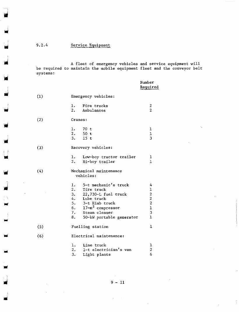
9.2.4 Serv ice Equipment -
be required to maintain the mobile equipment f leet and the conveyor bel t systems:
A f l e e t of emergency veh ic l e s and s e r v i c e equipment will
Number Required
Emergency veh ic l e s :
1. F i r e t r u c k s 2. Ambulances
Cranes:
1. 70 t 2. 50 t 3. 15 t
Recovery veh ic l e s :
1. Low-boy ' t r a c t o r t r a i l e r 2. Hi-boy trailer
Mechanical maintenance veh ic l e s :
1. 5-t mechanic's truck 2. Tire t ruck 3. 22,730-L f u e l t r u c k 4 . Lube t ruck 5. 3-t Hiab t ruck 6. 17-m3 compressor 7. Steam c leaner 8. 50-kW por tab le genera tor
F u e l l i n g s t a t i o n
Electr ical maintenance:
1. Line t ruck 2. 1-t e l ec t r i c i an ' s van 3. Light p lan ts
9 - 11
2 2
1 1 3
1 1
1 4
2 2
1 2
1 3
1
1 2 6
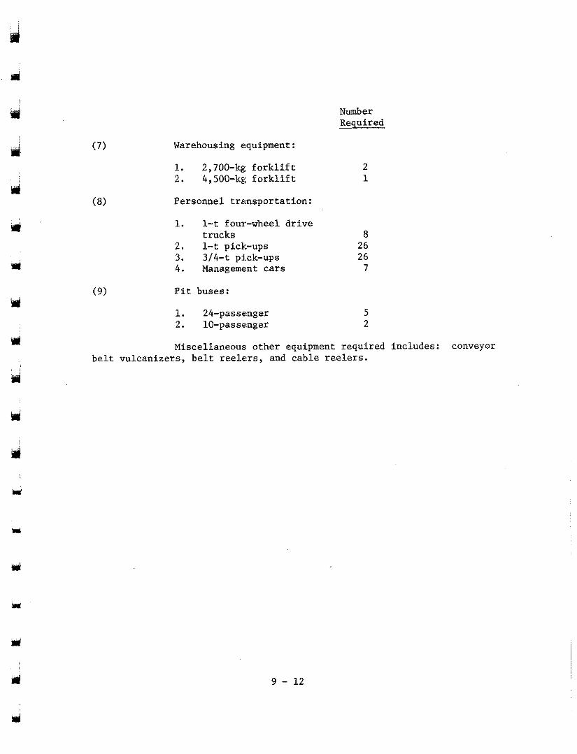
Warehousing equipment :
1. 2,700-kg f o r k l i f t 2. 4,500-kg f o r k l i f t
Personnel t ranspor ta t ion :
1. 1-t four-wheel drive t rucks
2. 1-t pick-ups 3. 314-t pick-ups 4. Management c a r s
P i t b u s e s :
1. 24-passenger 2. 10-passenger
Number Required
2 1
8 26 26
7
5 2
b e l t v u l c a n i z e r s , b e l t reelers, and cable reelers. Miscellaneous: other equipment required includes: conveyor
9 - 12
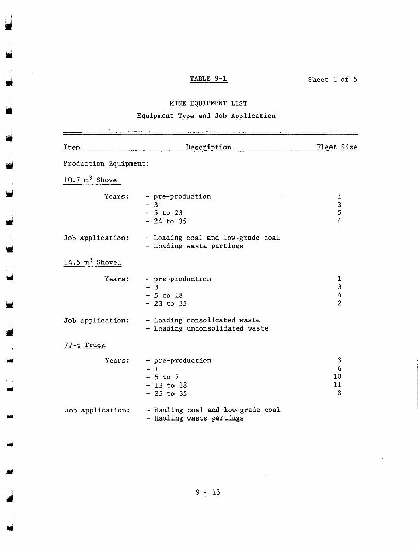
TABLE 9-1 Sheet 1 of 5
Y
ul
MINE EQUIPMENT LIST Equipment Type and Job Application
Item Description Fl.eet Size
Production Equipment:
10.7 m3 Shovel
Years :
Job application:
1 4 . 5 m3 Shovel
Years :
Job application:
77- t Truck
Years :
J
Job application:
- pre-production - 3 - 5 to 23 - 24 to 35
- Loading coal and low-grade coal - Loading waste partings
- pre-production - 3 - 5 to 18 - 23 to 35
- Loading consolidated waste - Loading unconsolidated waste
- pre-production - 5 t o 7 - 1
- 13 to 18 - 25 to 35
- Hauling coal and low-grade coal - Hauling waste partings
4
1
2
6 3
10 11
8
9 - 13
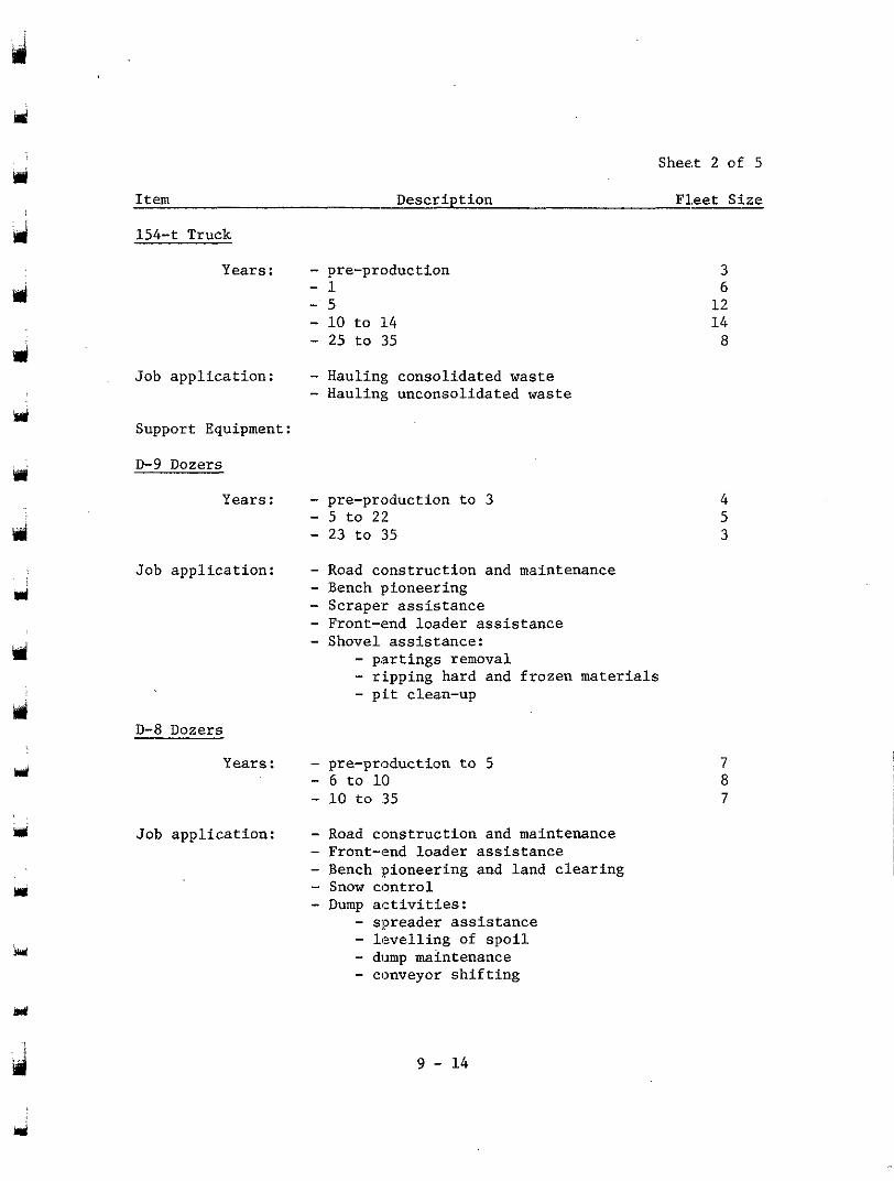
Shee.t 2 of 5
Item Description Fleet Size
jr
154-t Truck
Years : - pre-production - 1 - 5 - 10 to 14 - 25 to 35
Job application: - Hauling consolidated waste - Hauling unconsolidated waste
Support Equipment:
D-9 Dozers
Years : - pre-production to 3 - 5 to 22 - 23 to 35
Job application: - Road construction and maintenance - Bench pioneering - Scraper assistance - Front-end loader assistance - Shovel assistance:
- partings removal - ripping hard and frozen materials - pit clean-up
D-8 Dozers
Years : - pre-production to 5 - 6 to 10 - 10 to 35
Job application: - Road construction and maintenance - Front-end loader assistance - Bench pioneering and land clearing - Snow control - Dump activities:
- spreader assistance - levelling of spoil - dump maintenance - conveyor shifting
3
12 6
14 8
4 5 3
7 8 7
9 - 14
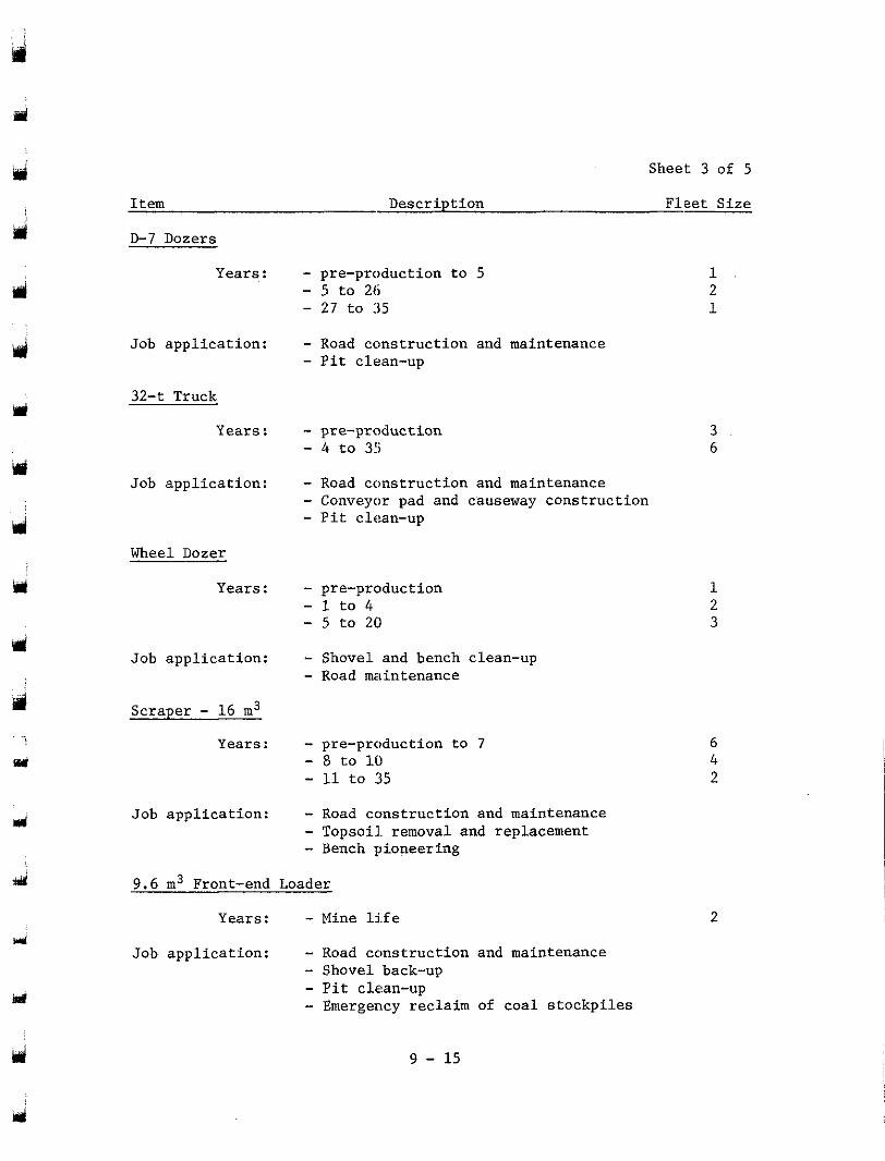
Sheet 3 of 5
Item Descr ip t ion F lee t S ize
D-7 Dozers
Years : - pre-production to 5 - 5 t o 26 - 27 t o 35
- Road cons t ruc t ion and maintenance - P i t clean-up
1 2 1
Job appl ica t ion :
32-t Truck
Years : - pre-production - 4 t o 35
- Road construction and maintenance
- P i t clean-up - Conveyor pad and causeway cons t ruc t ion
3 6
Job app l i ca t ion :
Wheel Dozer
Years: 1 2 3
- pre-production - 1 t o 4 - 5 t o 2 0
- Shovel and bench clean-up - Road maintenance
Job appl ica t ion :
Scraper - 16 m3
Years: - pre-production to 7 - 8 t o 10 - 11 t o 35
6 4 2
- Road construction and maintenance
- Bench pioneering - Topsoil. removal and replacement
Job appl ica t ion :
d 9.6 m3 Front-end Loader
Years : - Mine l j f e 2 rri
Job app l i ca t ion : - Road cons t ruc t ion and maintenance - Shovel back-up
- Emergency reclaim of coa l s tockp i l e s - P i t clean-up w
ei 9 - 15
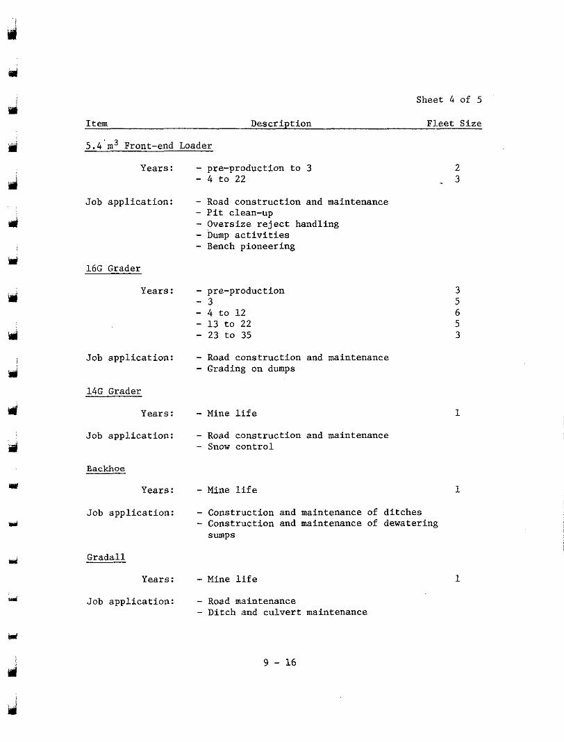
Sheet 4 of 5
Item Description Fl.eet Size
5.4'm3 Front-end Loader
Years : - pre-production to 3 2 - 4 to 22 - 3
Job application: - Road construction and maintenance - Pit clean-up
- Dump activities - Oversize reject handling - Bench pioneering
16G Grader
md
i
Y
Y
d
wl
U
Years : - pre-production - 4 to 1 2 - 3
- 13 to 22 - 23 to 35
Job application: - Road construction and maintenance - Grading on dumps
14G Grader
Years : - Mine life Job application: - Road construction and maintenance
- Snow control
Backhoe
Years: - Mine life
Job application: - Construction and maintenance of ditches - Construction and maintenance of dewatering sumps
Gradall
Years: - Mine life Job application: - Road maintenance
- Ditch and culvert maintenance
1
1
1
9 - 16
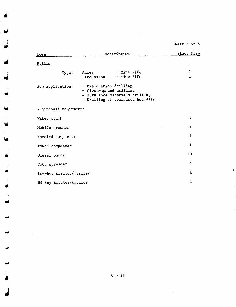
J
d
i
' m
Sheet 5 of 5
Item Description Fleet Size
Drills
Type: Auger - Mine life Percussion - Mine life
Job application: - Exploration drilling - Close-spaced drilling - Burn zone materials drilling - Drillhg of oversized boulders
Additional Equipment:
Water truck
Mobile crusher
Wheeled compactor
Towed compactor
Diesel pumps
CaCl spreader
Low-boy tractorttrailer
Hi-boy tractorttrailer
1 1
3
1
1
1
10
4
1
1
u'
J 9 - 17
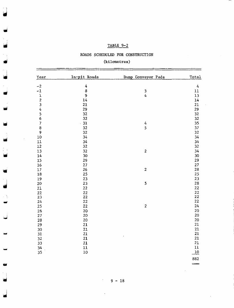
TABLE 9-2
ROADS SCHEDULED FOR CONSTRUCTION
(kilometres)
'd
iri
M
d
Year In-pit Roads Dump Conveyor Pads Total
-2 4 4 -1 1
8 9
3 11 4 13
2 14 3
14
4 21 21 29
5 29
6 32 32
7 32 32 31
8 35
32 37 9 32 32 10 34 34 11 34 12
34 32 32
13 14
32 34 30 30
15 29 29 16 17
27 27
18 26 28 25 25
19 23 23 20 23 28 21 22 22 22 22 22 23 22 22 24 22 22 25 22 24 26 20 20 27 20 20
29 21 21 30 21 21 31 21 21 32 21 21 33 21 21 34 11 11 35 10 - 10
28 20 20
882 - -
4 5
2
2
9 - 18
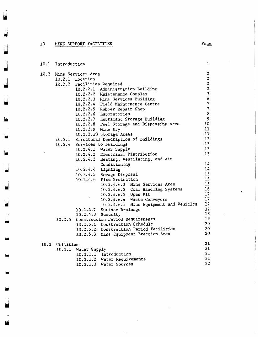
d
hi i
d
Y I
Y
d i
d
Y
Y
k d
md
Y
10 MINE SUPPORT FACILITIES
10.1 Introduction 1
10.2 Mine Services Area 2 10.2.1 Location 2 10.2.2 Facilities Required 2
10.2.2.1 Administration Building 2 10.2.2.2 Maintenance Complex 3 10.2.2.3 Mine Services Building 6 10.2.2.4 Fie1.d Maintenance Centre 7 10.2.2.5 Rubber Repair Shop 7 10.2.2.6 Laboratories 8 10.2.2.7 Lubricant Storage Building 9 10.2.2.8 Fuel. Storage and Dispensing Area 10 10.2.2.9 Mine Dry 11 10.2.2.10 Storage Areas 11
10.2.3 Structural Description of Buildings 12 10.2.4 Services to Buildings 13
10.2.4.1 Water Supply 13 10.2.4.2 Electrical Distribution 13 10.2.4.3 Heat.ing, Ventilating, and Air
Cond.itioning 1 4 10.2.4.4 Ligbting 14 10.2.4.5 Sewa.ge Disposal 15 10.2.4.6 Fire Protection 15
10.2.4.6.1 Mine Services Area 15 10.2.4.6.2 Coal Handling Systems 16 10.2.4.6.3 Open Pit 17 10.2.4.6.4 Waste Conveyors 17 10.2.4.6.5 Mine Equipment and Vehicles 17
18 17
19 10.2.5.1 Construction Schedule 20 10.2.5.2 Construction Period Facilities 20 10.2.5.3 Mine. Equipment Erection Area 20
10.2.4.7 Surface Drainage 10.2.4.8 Secu.rity
10.2.5 Construction Period Requirements
10.3 Utilities 10.3.1 Water Supply
10.3.1.1 Introduction 1 0 . 3 . 1 . 2 Wate.r Requirements 10.3.1.3 Water Sources
27 2 1 2 1 2 1 22
10.3.1.4 Proposed System 10.3.1.4.1 Source of Supply 10.3.1.4.2 Mine Services Area 10.3.1.4.3 Coal Blending Area 10.3.1.4.4 Overland Coal Conveyor 10.3.1.4.5 In-Pit Water Supply 10.3.1.4.6 Revegetation Nursery
10.3.2 Mine Power Supply 10.3.2.1 Introduction 10.3.2.2 Electrical Loads
10.3.2.2.1 Power Shovels 10.3.2.2.2 Voltage Regulations 10.3.2.2.3 Estimated Annual Power
Demands and Energy Consumption
10.3.2.3 Network Design Criteria 10.3.2.4 System Description
10.3.2.4.1 General 10.3.2.4.2 Pit Area 10.3.2.4.3 Houth Meadows Waste Dump 10.3.2.4.4 Medicine Creek Waste Dump 10.3.2.4.5 Mine Service Facilities 10.3.2.4.6 Crushing/Blending Plant 10.3.2.4.7 Reliability 10.3.2.4.8 Construction Power
23 23 23 24 24 24 25 25 25 25 25 26
26 27 28 28 29 29 30 31 31 31 32
3
3
3
m
d
ai i
iri
No. LIST OF TABLES - .
10-1 Preliminary Estimates of Consumptive Water Requirements 33
10-2 Water Quality Data 34
10-3 Total Estimated Mine Load During Peak Years 35
10-4 Estimated Annual Load and Energy Demands 36
10-1
10-2
10-3
10-4
10-5
10-6
10-7
10-8
LIST OF FIGURES
Mine Services Area - General Arrangement Administration Building
Maintenance Complex
Mine Services Building and Rubber Repair Shop
Mine Dry
Mine Power Distribution Network
Typical Portable Sub-station Layout
Typical Permanent Sub-station Layout
37
38
39
40
41
42
43
4 4
3
Y
d
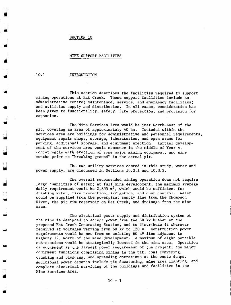
d
rpl i
Y
u
Y
m
10.1
SECTION 10
MINE SUPPORT FACILITIES
INTRODUCTION
mining operations at Hat Creek. These support facilities include an administrative centre; maintenance, service, and emergency facilities;
been given to functionality, safety, fire protection, and provision for and utilities supply and distribution. In all cases, consideration has
expansion.
This section describes the facilities required to support
pit, covering an area of approximately 40 ha. Included within the services area are buildings for administrative and personnel requirements,
parking, additional storage, and equipment erection. Initial develop- equipment repair shops, storage, laboratories, and open areas for
ment of the services area would commence in the middle of Year 4, concurrently with erection of some major mining equipment, and nine months prior to "breaking ground" in the actual pit.
The Mine Services Area would be just North-East of the
power supply, are discussed in Sections 10.3.1 and 10.3.2. The two utility services costed in this study, water and
large quantities of water; a.t full mine development, the maximunl average The overall recommended mining operation does not: require
daily requirement would be 2,855 m3, which would be sufficient for
would be supplied from the powerplant supply line from the Thompson drinking water, fire protection, irrigation, and dust control. Water
River, the pit rim reservoir on Hat Creek, and drainage from the mine area.
The electrical power supply and distribution system at
proposed Hat Creek Generatin.g Station, and to distribute it wherever the mine is designed to accept power from the 60 kV busbar at the
required at voltages varying: from 60 kV to 120 V. Construction power
Highway 12, North of the min.e development. A maximum of eight portable requirements would be met from an existing 60 kV line adjacent t:o
sub-stations would be strate.gically located in the mine area. Operation of equipment is the largest power requirement of the project, the major equipment functions comprising mining in the pit, coal conveying,
Additional power demands include pit dewatering, mine area light:ing, and crushing and blending, and spreading operations at the waste dunlps.
complete electrical servicin.g of the buildings and facilities in the Mine Services Area.
10 - 1
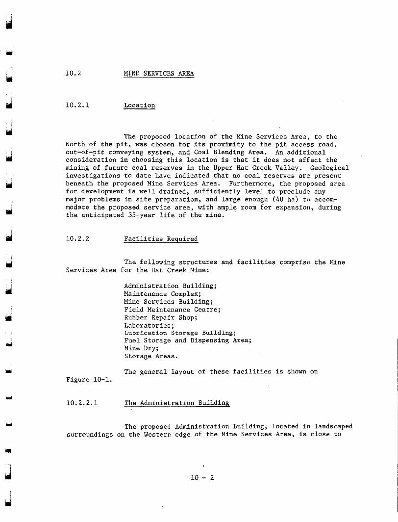
hd
Y
Y
10.2
10.2.1
MINE SERVICES AREA
Location
North of t h e p i t , was chosen f o r i t s p rox imi ty t o t he p i t a cces s road , The proposed loca t ion of t h e Mine Services Area:, t o t h e
out-of-pit conveying system, and Coal Blending Area. An a d d i t i o n a l
mining of f u t u r e c o a l reserves i n the Upper Hat Creek Valley. Geological cons ide ra t ion i n choos ing t h i s l oca t ion i s t h a t i t does no t a f fec t the
beneath the proposed Mine Services Area. Furthermore, the proposed area i n v e s t i g a t i o n s t o d a t e have indicated that no c o a l reserves a re p re sen t
major problems i n s i t e prepara t ion , and l a r g e enough (40 ha) to accom- f o r development i s well d ra . ined , su f f i c i en t ly l eve l t o p rec lude any
modate the proposed service. area, with ample room for expansion, during t h e a n t i c i p a t e d 35-year l i f e of t h e mine.
10.2.2 Faci l i t ies Required
Serv ices Area f o r t h e Hat Creek Mine: The fol1owin.g s t r u c t u r e s and f a c i l i t i e s c o m p r i s e t h e Mine
Administrati.on Building; Maintenance Complex; Mine Services Building; F ie ld Mainte.nance Centre; Rubber Repai.r Shop; Laborator ies ; Lubr ica t ion Storage Building; Fuel Storage and Dispensing Area; Mine Dry; Storage Areas .
The genera l l ayout of t h e s e f a c i l i t i e s is shown on Figure 10-1.
Y 10.2.2.1 The Administ.ration Building
rr surroundings on the Western edge of t h e Mine Services Area, is c l o s e t o
The proposed. Administration Building, located in landscaped
d L,
10 - 2
the entrance to the proposed project access road and is also easily accessible from all other facilities in the area (see Figure 10-1). The proposed building is a two-storey structure with a total floor ar'ea of 1,770 m2, containing 50 office spaces as well as adequate storage area, service facilities, and a conference room (see Figure 10-2).
senior staff members and service and administrative departments such as accounting, data processing, payroll, personnel, and purchasing. Engineering departments such as mine planning and geology would b'e located on the upper floor with adequate office space and drafting area.
The ground floor has been arranged to provide offices for
10.2.2.2 The Maintenance Complex
0.945 ha area, is centrally located in the Mine Services Area, providing easy access to the repair and service shops for the in-pit vehicl'es, as well as to the other support facilities such as the Rubber Repair Shop, Administration Building, and the Mine Dry (see Figure 10-1). The building layout is shown on Figure 10-3 and consists of the following
This structure, of dimensions 189.0 m x 50.0 m and
work and storage areas.
8 Haul truck repair bays 4 Tractor repair bays 8 Auto repair bays 2 Steam-clean bay/wash down bays Welding and fabricating shop Machine shop Electrical repair shop
Radio and instrument repair shop Hydraulic repair shop
Warehouse areas - palletized - small piece (shelved) - flammable goods store - tool crib
10 - 3
10.5 x 18.5 m
10.5 x 18.5 m 5 . 2 5 x 9.25 m 10.5 x 15.0 m
1,350 m2 850 m2
280 m2
60 m2 ZOO m2
2, 000 m2 385 m2 100 m2
70 m2
1
d
a
d
9
mi
d I
hd
Y
Y
Y
Planning area 300 m:!
Fire Truck Storage Bay 6.5 x 12.0 m
Ambulance Storage Bay 6.5 x 12.0 m First Aid Centre 78 m'! Training Centre 150 m'!
Mechanical service rooms 110 m'! Battery Room 25 m'!
The internal. layout of the maintenance complex 17as designed to the following assumed criteria:
(1) maintenance, planning, and supervisory office areas should be central and have easy access to all parts of the complex;
(2) the vehicle repair bays should be within easy reach of warehouse storage of spare parts and materials; and
(3) the vehicle repair bays should have easy access to ancillary repair and service areas such as the machine shop, welding and fabricating shop, etc.
The number of repair bays was determined by using anticipated mechanical availabilities for the various types of equipment.
compressed air, water, power, and oxyacetylene from bulk storage facilities. General service equipment such as welding machines, powered hand tools, welding screens, bench and floor-mounted grinders, and drill presses will also be supplied as required. In areas where fumes and dust will be a problem, such as the welding shop and steam bay, fume hoods and/or extractor fans should be provided.
All work areas in the complex will be supplied with
to specialized equipment. Each shop area will include a foreman's office j.n addition
The Truck Re.pair Shop
This will be equipped with a 30 t overhead e1ect:ric
floor level, to accommodate work on the 77 t and 154 t mine trucks. travelling crane fitted with a 5 t auxiliary crane, controlled from
Other equipment will include 100 t hydraulic jacks, a lubricati-on rack complete with hose reels to dispense all necessary fluids and greases in the service bays, and waste-oil disposal tanks from which the waste oil
Figure 10-1). A 10 m-wide concrete apron will be provided adjacent to is pumped to a holding tank. in the fuel storage and dispensing area (see
the entrances to this and the following two shops.
j 10 - 4
The Tractor Repair Shop
This w i l l be equipped with a 15 t ove rhead e l ec t r i c
was te -o i l d i sposa l sys tem, as descr ibed earlier, w i l l be supp l i ed i n t he t r a v e l l i n g c r a n e w i t h f l o o r - l e v e l c o n t r o l s . A l ub r i ca t ion r ack and a
serv ice bays .
The Auto Repair Shop
This w i l l be equipped with a 10 t overhead e lec t r ic c rane , p lus f loor -mounted hydraul ic vehic le l i f t s of 500 kg capaci ty .
The WeldinglFabricating Shop
This will be equipped with a 25 t crane, as earlier descr ibed, as well as 2 t j ib- type cranes. The spec ia l i zed equipment i n
cut ter , a i r -arcing equipment , b lacksmith furnace, and welding booths. t h i s shop should include a u n i v e r s a l i r o n w o r k e r , p l a t e r o l l s , p r o f i l e
The Machine Shop
This w i l l be. equipped with a 1 2 t overhead e l e c t r i c crane, p lus 2 t j i b c r a n e s t o s e r v i c e v a r i o u s machine too ls such as 750, 430, and 275 mm l a t h e s , 150 mm hor izonta l bor ing mill, 1,400 mm x 280 mm m i l l i n g machine, 2,000 mm r a d i a l arm d r i l l , 550 mm s t roke shaping machine, key-seater, surface plate, 75 t and 300 t hydraul ic p resses , cleaning tanks, and precision gauges. A strip-down and assemb1.y area w i l l be designated.
The E lec t r i ca l Repa i r Shop
This w i l l be equipped with a 12 t overhead crane and o t h e r r e l a t e d equipment such a s t e s t i n g equipment, cleaning tanks, and drying oven.
The Warehouse
This w i l l be equipped with 2,250 kg and 4,500 kg; capac i ty
unloading and s t o r i n g of pal le t ized par ts . Handl ing of l a r g e r and f o r k l i f t t r u c k s i n t h e covered warehouse area t o handle the loading,
heavier components w i l l be by mobile yard cranes as r equ i r ed , e . i t he r i n ou ts ide yards o r coa l s torage bu i ld ings . Smal l par t s w i l l b e s t o r e d i n b ins .
Necessary office space for warehouse personnel a.nd inventory records i s included.
d
d
yi
cii
Y
m
10 - 5
d
d
;li i 10.2.2.3 The Mine Services Bui lding
loca ted in the Eas te rn sec t ion of t h e Mine Services Area (see Figure 10-4) and covers an area of approximately 1.8 ha. It is eas i ly acces- s ib l e fo r " in -p i t ' ' and maintenance building requirements, as well as de l ive ry of raw ma te r i a l s and s p a r e p a r t s v i a t h e mine access mad.
This bu i ld ing , wi th its anc i l l a ry s to rage ya rd , is
The f o l l o w i n g s e r v i c e s a r e i n c l u d e d i n t h i s f a c i l i t y :
Sheet Metal and P i p e f i t t e r s ' Shop
Carpenters ' Shop
Pa in t e r s ' Shop
Supervisory o f f i ce space
Winter and/or night s torage for vehicles
(wi l l a:Lso serve as extra workspace
fo r ca rpen te r s and p i p e f i t t e r s when
requi red)
Mater ia l Storage Area and t o o l c r i b
Personnel areas - punch in /ou t a r ea ,
washrooms, locker space, lunchroom,
and j a n i t o r i a l room
Open s torage yard
Covered plywood and timber storage
215 m2
245 m2
95 m2
85 m2
400 m2
50 m2
200 m2
1.6 ha
100 m2
wi th necessary too ls and equipment as follows: The var ious shop a r e a s i n t h e b u i l d i n g w i l l be equipped
The Sheet Metal and P i p e f i t t e r s ' Shop
This w i l l be equipped with a sheet metal shear and former, spot welder, bench grinder, d r i l l press, p ipe th reader , bandsaw, overhead monorail and h o i s t . and miscellaneous handtools.
The Carpenters ' Shop
T h i s w i l l be equipped w i t h a bench saw, r a d i a l arm saw, d r i l l , p laner , and necessary handtools.
10 - 6
r
m
The Pa in t e r s ' Shop
This w i l l be equipped with portable spray paintin.g equipment.
An outs ide parking area, equipped with electrical plug-in r ecep tac l e s , w i l l be p rovided to accommodate overnight parking of miscel laneous service vehicles .
10.2.2.4 The Field Maintenance Centre
t h i s b u i l d i n g w i l l b e i n t h e f i e l d , and the re fo re no major equipment need b e supp l i ed i n t he bu i ld ing . Bench-mounted g r inde r s and a pedes t a l d r i l l p r e s s w i l l be i n s t a l l ed , a long w i th a welding machine and oxyacetylene equipment.
Most of t h e work ca r r i ed ou t by t h e crews opera t ing from
Service trucks equipped with welding machines, oxyacetylene equipment, compressors, l i f t i n g equipment, and handtools w i l l provide t h e s e r v i c e s r e q u i r e d f o r t h e f i e l d work. Line t rucks w i l l be ava i l ab le for maintenance of t h e mine e l e c t r i c a l power system.
Any o t h e r equipment required for major overhauls or major r e p a i r s w i l l be supplied from the maintenance complex or Mine Serv ices Centre.
10.2.2.5 The Rubber Repair Shop
shops for tires (225 m2), conveyor b e l t i n g (300 m2), and t r a i l i n g c a b l e s (225 m2), and is loca ted i n t he Sou the rn s ec t ion of the maintenance and
Figure 10-4). se rv ice a r ea w i th in ea sy access of t h e p i t and main conveyor routes ( see
This bui lding houses three separate service and repair
-,
easy access t o a hea ted conmete ap ron i n f ron t of t h e t i re r e p a i r Mine product ion vehic les requi r ing tire se rv ice will have
building, where tires w i l l be mounted us ing por tab le hydraul ic j acks and a 13,500 kg capacity forklift , complete with t i re manipulator attachment. Minor repairs only should be done in-shop while major repairs should be c a r r i e d o u t o f f - s i t e by a su i t ab le con t r ac to r .
9 I
a 'I 10 - 7
ui
m
Y
The Conveyor Belting Shop
The Conveyor :Belt Repair Shop will be equipped to handle belt splicing and belt repairs, both in the shop and in the field, using portable vulcanizing equipment suitable for use with steel cord or fabric ply belting. The ree,ls of belt will be handled by a mobile crane
reelers in the shop area. The shop will be equipped with all necessary in the storage area and by an overhead monorail at the powered belt
handtools such as knives and belt cutters. Power supply to this building at 600 v would be used directly for the vulcanizing equipment, while a
power tools, etc. A cold-storage building will be provided for proper step-down to 120 v would be necessary for lighting, heating, ventilation,
storage of conveyor belt splicing and repair materials.
The Cable ShoE
This area will be provided for repairing and testing mine
benches, test panels, overhead cranes, and necessary handtools. cables. Typical equipment in the shop includes powered reels, repair
10.2.2.6 Laboratories
The following laboratory facilities will be provided:
- an assay/environmental analytical laboratory in t:he Mine Services Area. (see Figure 10-1);
- an environmen.ta1 services complex sit,uated on a parcel of presently cdtivated land to the South-East of the pit near the confluence of Hat Creek and Medicine Creek (see Figure 10-2).
The Assay/Environmental Analytical Laboratory
Located adjacent to the Administration Building, this facility consists of:
- a general office area, conference room and receprrion area (300 m2);
- a "wet" laboratory area to be used by both environmental and assay staff for sample analysis;
- a dry-coal laboratory, used solely for coal samp:le analysis (150 m2);
- a core-sample handling area (150 m2); w
d 10 - 8
- a sample storage area (75 m2); - equipment storage (50 m2). A central enclosed walkway will separate the wet laboratory
will be taken to prevent dust emissions from the latter area. and office area from the dirtier, coal-handling facilities; precautions
Core storage sheds will be provided in the vicin3.ty of
being transported to the laboratory. A shed will also be provided for the Coal Blending Area, with. only sufficient core for analytical testing
logging and splitting cores.
Adjacent park.ing space will be provided for staff work vehicles and vehicles delive.ring samples.
The Environmental Services Complex
This group of structures will be.built on presently developed agricultural land (proposed as potential nursery area) and consist of:
- a "Lord & Burnam"-type greenhouse (aluminum and glass construction), heated, ventilated, and equipped with necessary lighting (105 m2);
- a "Quonset"-type greenhouse (50 m2);
- a service bui.lding containing reception area, office and drafting area.s, and sample preparation room (150 m2);
- a reclamation./agricultural machinery shed (300 m'!);
- bulk fertilizer storage (8 m2).
Ij
d
10.2.2.7 The Lubricant Storage Building
As shown in Figure 10-1, this building is located adjacent to the North-East corner of the maintenance complex to provide good
building should be heated an.d insulated and house bulk storage t:anks for access for both delivery vehicles and mine service vehicles. The
the various lubricating oils and greases required for the mine mobile equipment. The types and qu.antities of stored materials are as follows:
10 - 9
Motor oil 30 kL Hydraulic oil 30 kL Transmission :fluid 30 kL Gear oil 30 kL Chassis grease 9,000 kg Track grease 9,000 kg
The various lubricants will be pumped on demand in heated underground piping to the maintenance complex and then to dispensing racks in service bays in the truck, tractor, and auto repair shops.
The storage tanks of mine lube trucks will be replenished at an external loading station forming part of the building. A portable lube island in the mine complements this facility and will be located conveniently close to the main haulage route for quick servicing of
equipment will be serviced on location by the lube truck. trucks whenever necessary. :Less-mobile equipment such as tracked
10.2.2.8 The Fuel Storage and Dispensing Area
d
j
3
ri
13
pumps will be located in the Eastern edge of the Mine Services Area, close to the main mine haulage access road and approximately 100 m from the maintenance complex. Access will be provided around the tank farm for the mine fuel trucks, ot'her service vehicles, pick-up trucks, and
around the farm area to contain any spillage of fuel. the fuel supplier's tank truck. A safety berm will be constructed
A fuel tank farm with diesel fuel and gasoline dispensing
anti-freeze, and waste oil storage tanks of 364 , 90, 55, and 45 kL, respectively, these amounts of fuel being equal to approximately one week's predicted consumption rates.
The tank farm will contain diesel fuel, gasoline, mixed
Metered bulk loading and unloading facilities for use by the mine fuel trucks and fuel supplier's trucks, as well as dispensing pumps for the general mine use, will be supplied in this area.
An in-pit fuel facility is also provided for the use of the haulage truck fleet and is located in the same area as the in-pit lube island. Other mobile equipment such as tracked vehicles will be fuelled by the mine fuel trucks. The fuel island, receiving its supplies
mounted diesel fuel tanks of approximately 45 kL total capacity, provided from the supplier's tank truck as required, will have portable horizontally-
with trays to contain accidental spillage, and will be complete with metered loading and unloading facilities.
10 - 10
10.2.2.9 The Mine Dry
rii
The Mine Dry will be divided into four basic areas
marshalling area. Provision will be made for installation of 700 dirty lockers, clean lockers, washing area, and mine supervision and
"clean" lockers and 700 "dirty" lockers so as to allow a locker of each type for every person on the mine labour force (see Figure 10-5).
Janitorial space and mechanical equipment rooms wfll also be provided.
Separate dry areas will be provided for male staff members as well as female work crew members.
The heating and ventilating systems will be designed to accommodate the hot and humid conditions expected in a washroom area. The ventilation system will be designed so that the air is directed through the locker spaces to facilitate drying of clothes, and then into
materials, and provision of a full complement of hydrants and fire the building. The building will be constructed of non-combustible
extinguishers is recommended, rather than installation of a sprinkler system.
10.2.2.10 Storage Areas
, .
u
The location a.nd size of various storage facilities in the mine service area have be.en based on consideration of their expected use, access from the work areas in which the stored materials are to be
monitor incoming and outgoing. materials, and the possible need for used, the ease of moving materials within the storage area, the need to
future expansion.
described below. The main stora.ge areas are shown on Figure 10-1 and are
Yard storage
An area of approximately 3 . 6 ha will be fenced and manned for materials control. Large: parts requiring covered storage wil.1 be
will be arranged to allow easy access for service vehicles and yard housed in an unheated building constructed of light metal. The area
cranes.
10 - 11
Shop area stor-
Individual storage areas are recommended for the parts and materials used in the various shop areas. The area recommended (approximately 2.7 ha) is centred mainly around the Mine Services Building and Rubber Repair Shop, where a large area is required for storage of tires, rolls of belting, cable reels, and lumber.
will be provided to permit the secure storage of small vehicle tires. Various rubber repair materials may be stored in a refrigerated building within this fenced area.
A separate fenced area adjacent to the Tire Repair Shop
Construction' storage area
The construction storage, or "laydown", area will be used
period, and thereafter for the storage of supplies for the pit and mine initially for the storage of materials and equipment during the construction
service area.
4 !
Isi
10.2.3 Structural Description of Buildings
frame over reinforced concrete floors and footings. Where necessary, structures will be designed for extra loading imposed by travelling cranes, overhead office space, heating and ventilating units.
Buildings wi1:L be constructed of light structural steel
cladding, as specified and detailed by Toby, Russell, Buckwell and External walls will generally be built of insulated metal
Partners, architectural consultants to B.C. Hydro. Sections of the wall adjacent to vehicle access roads or doors into the building will be constructed of reinforced concrete to doorhead height, so as to minimize damage in case vehicles collide.
or moveable prefabricated panels. Internal dividing walls will be built of concrete blockwork
will be sufficiently sloped t o facilitate proper drainage. The (exterior Roofs will be constructed of insulated metal cladding and
cladding is insulated to conserve heat in Winter and keep the shops cool in Summer. The thickness of insulation is designed to accommoda:te the
with the wall cladding, the roofing is specified and detailed by the large variations in temperature expected in the Hat Creek Valley. A s
architectural consultant.
d 10 - 12
ui !
d
ul:
shops, shop floors will generally be constructed of reinforced #concrete,
worked areas, a chemically-hardened wearing surface will be applied to using only a hard abrasion-resistant aggregate. In particularly hard-
minimize surface break-up and "dusting". To permit a good workable floor, special consideration will be given to producing a well-compacted, capable, load-bearing sub-grade. ,As drainage of shop areas is of prime importance, care should be taken in pre-designing all floor openings and trenches for services such as water, electrical cables, and exhaust piping, so as to prevent fut:ure disruption of drainage systems.
Because of their very rough usage in heavy-duty :repair
10.2.4 Services to Ruildings
d 10.2.4.1 Water Supply
. .
a
w
n
m'
Water will be provided to all buildings in the MLne Services Area by a buried pipe reticulation system.
10.2.4.2 Electrical Distribution
will receive incoming power supply at 6.9 kv transmitted via underground cable. A MVA 6.9 kv t o 600/347 v sub-station will be located adjacent to each building. The large-size and high Winter heating load of the maintenance complex will necessitate three 1 MVA sub-stations, one to be
sub-stations will be distributed within the buildings at 600/347 v with located centrally and one at each end of the building. Power from these
600 v receptacles provided throughout. Transformers of 600/120 v and panel boards complete with single-phase 120 v circuitry and receptacles will be provided where necessary. The type and number of power outlets will be designated according to the layout and designed use of each building, and an adequate number of spare panel board circuits will be made available to allow for future growth of building power load.
Each of the maintenance, office, and service buildings
In workshop areas such as the machine shop and welding/ fabricating shop, a plug-in three-phase 600/347 v bus duct will be used. This bus duct will be suspended from the ceiling structure of the building and provides a high degree of flexibility in future equipment locations.
10 - 13
d
10.2.4.3 Heating, Ventilatinp, and Air Conditioning
conditioning systems will be provided for the Administration Bui.lding, as well as the office areas in the mine dry and maintenance comp.lex. Ventilating systems will be provided throughout all buildings, w:ith special attention given to hazardous areas such as the Paint Shop, Woodworking Shop, and Rubber Repair Shop.
Electrical heating units are planned throughout, .and air
10.2.4.4 Lighting
l
ri
Lighting in maintenance and service facilities is designed to standards recommended by t:he Illuminating Engineering Society. Specific recommendations for lighting fixtures and intensity are as follows :
(1) In any inside work area of high-ceiling bays with a ceiling height
be spaced so as to provy.de even light intensity; greater than 4.0 m, 1,000 w high-intensity discharge lamps :should
(2) Office areas should be ].it with 4-tube, 1.2 m fluorescent luminaires;
(3 ) Where required, outdoor lighting should be provided by 1,000 w high-intensity discharge lamps. The fixtures should be suspended from buildings themselves, where possible, or mounted on po:les or towers;
(4) Emergency lighting fixtures should be provided in stairways and passageways of all buildings. Self-contained twin lamp battery packs will be used;
(5) Lighting in hazardous areas such as the Rubber Repair Shop, Paint Shop, and lubricant storage area should be provided, using :suitably enclosed and sealed 3-tube, 1 . 2 m fluorescent units.
id
. .
d
10 - 14
10.2.4.5 Sewage Disposal
pre- t rea ted and d ischarged to a holding pond, and w i l l be seasonal ly used f o r d u s t c o n t r o l i n t h e mine. Allowance has been made f o r .a package wastewater treatment p lan t capable of handling 140 m3/d of e f f l u e n t a t 400 ppm BODg.
S a n i t a r y e f f l u e n t from t h e mine s e r v i c e complex w i l l be
I f necessary, the t reated eff luent could be dis in .Eected
has been made f o r t h i s a t present . p r i o r t o being sprayed on r o a d s i n t h e mine a rea ; however, no provis ion
Water from equipment washdown f a c i l i t i e s w i l l be tdis- charged t o s tormwater drains via a grease and g r i t t r a p , from whare i t w i l l f low to sedimentation lagoons for primary treatment prior to discharge. The i n t e g r a t i o n of t h e s e f a c i l i t i e s i n t o t h e o v e r a l l mine drainage and water supply systems is d iscussed fur ther in Sec t ion 6 .
10.2.4.6 Fire P ro tec t ion Systems
cap i t a l i nves tmen t i n bu i ld ings and equipment and t o minimize the danger of f i r e c a u s i n g a major shutdown of coa l supply to the genera t ing s t a t i o n .
A f i r e p r o t e c t i o n s y s t e m w i l l be provided to protect
Permanent automatic systems w i l l b e i n s t a l l e d i n high- r i s k a r e a s . Where there is "medium" r i s k , a permanent water supply w i l l be provided f o r hoses o r fire t rucks . There w i l l be no permanen't i n s t a l l a t i o n s i n l o w - r i s k areas; s p o t f i r e s w i l l be extinguished by f i r e t rucks suppl ied by water tankers .
10.2.4.6.1 The Mine Services Area
nl
development, and insurance urlderwriters' standards have been used to de f ine f i r e p ro t ec t ion r equ i r emen t s . Automatic f i r e de t ec t ion sys t ems w i l l b e i n s t a l l e d i n a l l bui ld ings , wi th a cen t r a l a l a rm pane l i n t he proposed f i r e t r u c k bay.
This i s a r e l a t ive ly h igh - r i sk area wi th in t he mine
10 - 15
d
.eii i
. . . ,
is
Y
u
Automatic sprinkler systems are proposed f o r a l l main- tenance workshops and service bui ldings other than the Adminis t ra t ion Building and Mine Dry Building, which would be r e l a t ive ly l ow- r i sk a reas , cons t ruc t ed of non-combustible materials.
ex t ingu i she r s , a s well as 40 mm standpipes complete with run-out hoses s i t ua t ed t o p rov ide cove rage of t he bu i ld ing f l oo r p l an .
A l l bu i ld ings w i l l have a s tandard complement of f i r e
F i r e hydran t s w i l l be loca ted wi th in the se rv ice area, so as t o f u r t h e r p r o t e c t b u i l d t n g s and t h e open yard storage areas around the per imeter .
a r e se rve of 1,000 m3 of water f o r f i r e f i g h t i n g , and w i l l be capable of supplying 95 L / s a t 415 Ha a t connec t ions to bu i ld ings .
The water supply system to the service area w i l l maintain
Two four-wheel drive f i re t rucks w i l l be based a't the Mine Serv ices Area which w i l l be used as requi red th roughout the en t i re mine development area. These trucks w i l l carry about 2,000 L of water, f i r e pumps, hose reels, and ladders .
10.2.4.6.2 Coal Handling Systems
and the Overland Conveyor t o t h e g e n e r a t i n g s t a t i o n w i l l be under the su rve i l l ance of an automatic: f i r e d e t e c t o r s y s t e m which w i l l i d e n t i f y the l oca t ion of a f i r e and prevent i ts spread by stopping the conveyor.
The Coal Conveyor from t h e p i t t o t h e Coal Blending Area
Overland Conveyor w i l l be p ro tec ted by automatic spr inkler systems fed Conveyor transfer s t a t i o n s and enclosed sections of the
of conveyor w i l l be p ro tec ted by f i r e trucks which w i l l gain access by a from a buried water main ad jacen t t o t he conveyorway. Exposed :;ections
proposed service road, and will draw water from f i r e h y d r a n t s a d j a c e n t t o t h e conveyor. I n t h e Coal Blending Area buried water mains between
be provided between stockpi1.e~ to al low access for f i r e t rucks and t h e s t o c k p i l e s w i l l supply water to f i r e hydrants . Service roads w i l l
crews.
10 - 16
10.2.4.6.3 The Open Pit
: i
d
ui
be used to extinguish spot f:€res. A permanent water supply will be Within the open pit, water tankers and fire trucks will
available from the water main at the North conveyor incline; a hydrant will be provided at each bench. A further allowance has been made for 10,000 m of 75 mm aluminum p.ipe should an in-pit water supply main be required during mining operations.
10.2.4.6.4 Waste Conveyors
!
Y
n
Y
detection system similar to that for the coal conveyors. Permanent fire protection systems will not 'be installed on the conveyorways to the waste dumps and water tankers; fire trucks will be used instead.
These systems will be surveyed by an automatic fire
10.2.4.6.5 Mine Equipment and Vehicles
for vehicle safety. Supervisors' and safety officers' vehicles will carry larger units for emergency use on mine equipment.
All mine vehicles will be equipped with portable extinguishers
10.2.4.7 Surface Drainas
Area, a comprehensive system of ditches and culverts is recommen.ded to cope with the estimated 10-year flood. This will be the stormwa.ter collection system.
Because of the need for ample drainage in the Mine Services
basins will be routed through the centre of the maintenance and service area to receive runoff from the central yard area, as well as th.e roof
Maintenance Complex. drainage from the Administration Building, Laboratory, Mine Dry, and
A 750 mm corrugated steel pipe installed with cat:ch
Y
ri 10 - 17

d
d
d
PJ
i d
I
and service shops should be drained by means of a network of d i t ches channel l ing the runoff to the water t reatment area. To f a c i l i t a t e t h i s drainage, general areas should be s loped at 0.5% to per imeter d t tches o r ca t ch bas ins , and buildings would be drained via 300 mm buried corrugated p i p e s t o t he pe r ime te r d i t ches o r cen t r a l 750 mm pipe.
Storage areas, parking areas, general landscaped areas,
a t t h e West end of t he s e rv i ce a r ea , from where i t would be ca r r i ed by c u l v e r t s and di tches to the sedimentat ion lagoons. Sewage e f f l u e n t and
drain system and fed to the l eacha te s torage l agoon. l eacha te from coal-handling plant areas w i l l b e c o l l e c t e d i n a s epa ra t e
A l l of the runoff f rom this area is planned t o be co l lec ted
10.2.4.8 Security
will enclose the Mine Services Area, the Coal Blending Area, and the cons t ruc t ion s to rage a r ea . Th i s ba r r i e r w i l l be a heavy duty mesh fence topped with a barbed-wire st:rung overhead section.
It is in tended tha t a 2 m high maximum s e c u r i t y b a r r i e r
fol lowing four points around i t s perimeter:
(1) A main entrance from the publ ic access road w i l l l ead in to the Mine
Cont ro l led access to t h i s a r e a w i l l be provided a t t h e
Services Area and the en t r ance t o t he p i t and blending areas. A guardhouse will be provided a t t h i s e n t r a n c e t o m a i n t a i n a 24-hour
w i l l be large enough for two opposite f lows of t r a f f i c , w i t h the f u l l s e c u r i t y check of incoming and outgoing t r a f f i c . The entrance
guardhouse located cent:rally between the traffic lanes;
(2) A second entrance from the main access road to the coal-blending yard i s planned, b u t a permanent guardhouse w i l l not be provided. It is intended that this gate be locked and opened as requfred by se l ec t ed mine personnel.;
(3) A ga te w i l l be p rovided in the v ic in i ty of the main conveyor t r ans fe r po in t and ad jacent to the Houth Meadows Waste Conveyor f o r the use of the conveyor service crews with their vehicles .
( 4 ) A s imi l a r ga t e w i l l be provided adjacent to the Medicine Creek Waste Conveyor.
10 - 18
mi
3
Y
d
s t r u n g a c r o s s Hat Creek Va l l ey ad jacen t t o Highway 12 t o d i scourage publ ic en t ry to the conges ted area i n t h e v a l l e y bottom between t h e blending area and t h e Houth Meadows Retaining Embankment. A 1oc.kable g a t e w i l l be p rovided across the ex is t ing Hat Creek road.
North of t he p ro j ec t a r ea , s ecu r i ty f enc ing w i l l be
Secur i ty fenc ing w i l l also be provided around the l a r g e r , f i x e d e l e c t r i c a l s u b - s t a t i o n s . S e c u r i t y and s a f e t y b a r r i e r s f o r o t h e r e l e c t r i c a l components, moveable o r f i xed , w i th in t he mine area are inc luded i n t he des ign and construction of those components. A f u r t h e r run of s ecu r i ty f enc ing would surround the explosives magazine. In to ta l , approximate ly 7.5 km of secu r i ty f enc ing is t o b e i n s t a l l e d .
A s t h e mine w i l l opera te on a 24-hour bas i s , gene ra l
lumination of s e l e c t e d areas should be considered by t h e mine s e c u r i t y l i g h t i n g f o r t h e s e c u r i t y f e n c e need not be provided, but future il-
personnel .
w i th in a low-secur i ty bar r ie r to keep ou t l ives tock , as well as t o provide a v i s u a l d e t e r r e n t t o t h e p u b l i c . T h i s b a r r i e r would be a three-strand barbed-wire fence strung between 1.5 m high metal pos t s a t 4 m i n t e r v a l s . A t t h e commencement of mining operations, 24 km of t h i s
and t h e Houth Meadows Waste Dump, and up bo th s ides of t h e main coa l type of fencing should be erected around the 35-year limits of t h e p i t
be erected around the 35-year Medicine Creek Waste Dump and Waste conveyor. In about Year 16, a f u r t h e r 14.5 km of ranch fencing should
Conveyor. A fenced corridor should be provided through the project area for the d iver ted access road to the Upper Hat Creek area. Notices should be posted a t s u i t a b l e i n t e r v a l s around this fencel ine, warning peop le aga ins t t r e spass fo r t he s ake of t h e i r own sa fe ty .
I t i s proposed t o e n c l o s e t h e e n t i r e mine p ro jec t a r ea
10.2.5 Construction :Period Requirements
ment w i l l be required during construct ion of t h e permanent mine support f a c i l i t i e s . These temporary f a c i l i t i e s are out l ined below.
Temporary f a c i l i t i e s f o r p e r s o n n e l , materials, and equip-
Y
Y
10 - 19
eil
! Y
urr
d
10.2.5.1 Construction Schedule
f a c i l i t i e s w i l l be ready for use when. requi red for the genera l min ing According to t h i s s chedu le (Sec t ion 12 ) , a l l mine support
operat ions. The schedule takes into account engineering and purchasing, an t i c ipa t ed de l ive ry pe r iods , and assembly of equipment and materials.
10.2.5.2 Construction l?eriod Facilities
C o n s t r u c t i o n p e r i o d f a c i l i t i e s would include a temporary camp t o house the construct ion work fo rce ; t he camp does not form part of t h i s s t u d y and is not d i scussed fur ther . It is assumed t h a t t h e supply of the necessary construct ion bui ldings, shops, e tc . , would be t h e r e s p o n s i b i l i t y of t he r e spec t ive con t r ac to r s du r ing cons t ruc t ion of t he va r ious s t ruc tu res and e r ec t ion of the i n i t i a l mining and conveying equipment. It is assumed t h a t temporary o f f i c e and warehousing f a c i l i t i e s would be erected t o house the construct ion management team and B.C. Hydro’s construction and management group during the construct ion period.
10.2.5.3 Mine Equipment Erec t ion Area
the Northern end of the proposed mine perimeter, close t o the conveyor ramp, the Mine Serv ices Area,, and serv iced by access roads f o r t h e movement of materials and equipment. The area is l a r g e enough f o r t h e s imultaneous erect ion of two mining shovels, and has sufficient :storage
as well as fo r va r ious small bui ld ings , o f f ices, and o the r f ac i1 : i t i e s . space fo r miscellaneous components of o the r equipment awai t ing e rec t ion ,
A mine equipment e r e c t i o n area of 12 ha i s provided a t
The area will be well drained and suppl ied with water and power.
10 - 20
10.3
10.3.1
10.3.1.1
UTILITIES
Water Supply
Introduction
supply requirements for the mine development and describes the layout of This section of the report presents the estimated water
the proposed supply and distribution systems. Consideration was given to the integration of the min.e supply with parallel systems proposed for the thermal generating station and the construction camps.
10.3.1.2 Water Requireu9
iri
ai !
Y
The mine and a.djacent service complex will require a
mine water supply system must. provide for the estimated demand from the permanent water supply during; the years of operation of the mine.. The
following areas and services:
Potable Water for the Mine Services Area
Fire Protection Systems
Washdown Water
Irrigation Wat.ers
Dust Control
d Temporary Construction Supply
Administration Building Mine Dry
maintenance buildings laboratories
buildings
overland coal conveyor in-pit coal conveyor
Coal Blending Area
vehicles and equipment:
mine service area lawns and landscaping revegetation nursery
roads Coal Blending Area low-grade coal stockpfle
during construction of the Mine Services Area
d i
10 - 21
d i
iri
wl
mine at full development is shown on Table 10-1. Fire requirements are not shown as they do not form a day-by-day consumptive demand. Fire protection for buildings in the Mine Services Area would require the provision of 1,000 m3 of reservoir capacity and a flow of 95 L/E: at a residual pressure of 415 kPa at risers (M €X M Consultants 1978). At the Coal Blending Area allowance has been made for a flow of 30 L/s at 415 H a for fire control at the stockpiles.
A preliminary estimate of the water requirements of the
supply are presented by Beak (1978). These criteria were utilized in the selection of the source for these systems. The quality of dust
be satisfied by recycling wastewater from the mine operation. control water is, however, not critical, and the supply requirements may
Water quality standards for potable and irrigation water
10.3.1.3 Water Sources,
are discussed in detail in the CMJV Feasibility Report Vol. IV. Four alternative sources of supply were considered and
- Water from the proposed generating station supply which will be taken from the Thompson River;
- Surface water from the proposed Hat Creek Diversi.on Canal located to the East of the mine;
- Groundwater from a well sunk to the North-East of the Mine Services Area;
- Recycled mine wastewater. The major factors in the selection of a suitable source
are water availability, cost of treatment, and supply. The 1oca.tions of ancillary plant and mine facilities were considered as well, in order to provide an integrated system and to avoid duplication. r
3 10 - 22
10.3.1.4 Proposed Water System
d
u
ry
10.3.1.4.1 Source of SUE&
Water for the mine development will be supplied from the following sources:
Potable Water and Fire Protection
Water for these uses will come initially from an integrated groundwater supply system wi.th the project, temporary construction supply. When the permanent generating station supply from the Thompson River comes on line, the construct,ion supply pipeline from Hat Creek Valley to the powerplant will become the main supply line for potable water in the Mine Services Area. This wa'ter will require minimum treatment prior to
A backup supply could also be provided by the use of treated surface use. Fire protection requirements will also be supplied by this line.
water from Hat Creek.
Irrigation
Water for irrigation will be supplied from the Pit Rim Reservoir to the South of the open pit.
Dust Control
These requirements would be satisfied by recycling waste- water and pit dewatering flow.
drainage and water supply flow chart, Figure 6-3 in Section 6. The proposed water supply system is shown on the mine
10.3.1.4.2 Mine Services-
The Mine Services Area would be fed from a reservoir located near the proposed construction camp. A booster pumphouse at the Eastern perimeter would increase line pressure to 700 kPa using two electric pumps
would also be installed to provide water for fire control in the case of of total capacity 100 L/s. A gasoline-driven fire pump of 100 L / s capacity
ri 10 - 23
power failure. A water main approximately 1,700 m x 200 mm would provide
buildings, supply fixed sprinkler fire protection systems in buildings, a water supply for the Mine Services Area, provide potable water to
and fire hydrants in open yard storage.
10.3.1.4.3 Coal Blending Area
fire protection system at the Coal Blending Area. Buried mains approximately 2,100 m in length beneath the stacker corridors would supply water t o
control would be provided by oscillating water jets which could be fire hydrants located at 100 m spacing between the coal piles. Dust
mounted between the stacker rails and reclaimer units. During Summer the dust control system would be fed from the leachate holding pond as part of an evaporative disposal system for leachate. Make-up water to the system and fire reserve would be provided by the open pit fire protection supply.
Provision has been made for a permanent dust control and
10.3.1.4.4 Overland Coal Conveyor
stations will be supplied from a buried main following the conveyor. A Water for fire protection of conveyor belts and transfer
service road along the conveyor will allow access by fire truck to hydrants along the conveyor route. Frost protection may be required to prevent freeze-up of this pipeline during Winter. The relatively high head l o s s in the pipe (i.e., 450 m over its 4 km length) may require water hammer protection and pressure-reducing valves at lower points of supply.
10.3.1.4.5 In-Pit Water !=
water main on the main conveyor incline to provide a supply of w.?+ter for fire protection of the conveyor and loading stations. Further p.rovision has been made for 10,000 m of 75 mm aluminum in-pit distribution main which would be available for temporary use. The primary source o f water for dust control on pit roads would stem from the reclaim water ,system, which recycles wastewater from the leachate holding pond. Make-.up water for this system would come from pit dewatering flows or the permanent fire supply, as required.
Allowance has been made for the construction of a 150 mm
10 - 24
d
10.3.1.4.6 Revegetation Nursery
mine would be remote from the Mine Services Area and would therefore The proposed Revegetation Nursery to the South of the
have a separate water supply.
Water would be taken from the pipeline which interconnects the Pit Rim Reservoir with t:he Hat Creek Diversion Canal and supplied to irrigation spray systems.
Potable water requirements at the adjacent reclamation laboratory would be provided by a small package water treatment unit.
10.3.2 Mine Power Sc&
Y
10.3.2.1 Introduction id
19 distribution system used on the basis of estimating the cost of supplying power to the pit, waste dumps, and support facilities. The network developed includes all electrical equipment required to supply power from the 60 kV busbars of the proposed Hat Creek generating sta.tion to the open pit and dump areas,, and to distribute the power within these areas to the shovels, conveyors, spreaders, and to the crushing and blending equipment. The developed network also includes supply for the various service buildings and provides the construction power required during the development phase of the mine.
This section of the report describes the electrical power
10.3.2.2 Electrical L(+ Y
4
md
Mi
i
10.3.2.2.1 Power Shovelrr
shovel consists of a large surge of power required to hoist and swing the load to a small load during the dump portion of the cycle.
The load cyc:te for a large electrically-powered hydraulic
10 - 25
d
rrl
d
The acceptability of such a load, or the need to compensate for the power swings generated, can only be resolved through a &m- prehensive study of the utility network. However, the proximity of the proposed generating station to the Hat Creek Mine and the choice of shovels equipped with rectifier inverters should preclude the need for any additional compensating equipment.
result in lower energy consumption due to a reduction in machine losses from approximately 10% for th.e normal Ward Leonard system to approximately 3% for the inverter system. In addition, shovel availability will be increased due to the reduced maintenance required by the solid-state
maintenance level of the rectifier inverter shovels is expected to more equipment relative to r0tatin.g machinery. The reduced losses and
than offset any additional capital costs involved.
The use of rectifier inverter-equipped shovels will
10.3.2.2.2 Voltage Regula.-
a iarge reactive power demand. upon the transmission network and, accordingly, a significant drop in voltage at the terminals of the motors. These voltage drops can be compensa.ted for by the use of appropriate equipment comprising either synchronous or static compensators. At Hat Creek, the use of static capacitors on bdividual motor loads would be restricted to the pre-production years, when limited construction power is available for operation of the pit and the Houth Meadows Waste Dump.
The start-up of large motors results in the imposition of
that the main 60 kV lines are installed to the powerhouse. No voltage regulation problems are foreseen at the time
10.3.2.2.3 Estimated Annual Power Demands and Energy Consumption
Table 10-3 shows the estimated mine loads for peak consumption during Years 22 t:o 25, inclusive. The three types of load specified on the table are defined as follows:
Connected Loac!
This is the sum of all equipment and motor loads installed in the plant or site.
10 - 26
d
w
bd
J
Typical Load
This is the load most likely to be exerted upon the power supply system during normal production periods.
Annual Average-
Although this load never actually applied to the power system, this is an estimate of the annual energy consumption presented as a continuous load.
The estimated annual power demands and energy consumption for Years 2 to 35, inclusive, are listed on Table 10-4.
10.3 .2 .3 Network Design Criteria
I has been developed on the basis of the following criteria: The proposed electrical system is shown in Figure 10-7
Two mine feeders will be available from B.C. Hydro at the H.at Creek Generating Station's 60 kV busbar; each of these feeders are capable of supplying the total mining load, make-up water for the generating station, and ash disposal pumping requirements;
Construction power at 60 kV will be available from the existing powerline at the junction of Highway 12 and the present Hat Creek road;
Houth Meadows and Medicine Creek Waste Dumps will take place over a Development of the major supply network to the open pit and to
period of 14 years. Primary distribution network through0u.t the complex will be rated at 60 kV, while supplies to shovels, con- veyors, etc., will be rated at 6.9 kV. Auxiliary mine equipment, pumps, lighting, and air compressors, together with interna.1
building voltages will be 120 v single-phase, where desirable. systems for auxiliary buildings, will be 600/347 v, while other
Transformers will be selected to be interchangeable within standard ratings;
The'rating of the apparatus, transformer impedances, line aad cable conductor, etc., will be sized such that the voltage fluctuation at the terminals of a shovel will not exceed +lo%, -5% under the worst operating conditions. Voltage regulation of the 60 kV power supply from the Hat Creek Generating Station is not expected to ex:ceed 25%;
10 - 27
3
ui
d
rrl i
(5) The electrical power network for the mine has been designed based on the overall economic optimization of both the remote power loads from the generating station and the remote mining loads, un.der the control of a single operating entity;
(6) Power distribution within the pit and waste dump areas will be by
will be generally TYPE SHD-GC, three-conductor with two ground and portable sub-stations and power cables. The portable power cables
one ground check conductor terminated at their extremities with plug and socket-type couplers. The portable sub-stations will be of one common design and will consist of the following elements:
- A portable high voltage (60 kV) switching unit;
- A skid-mounted 4 MVA 60 kVl6.9 kV 3 PH., 60 Hz oil-filled transformer;
- A portable 6.9 kV totally enclosed switching unit complete with three feeder circuits and female cable couplers;
- A portable low-voltage 600/347 v switching and distribution unit complete with 600 v female cable couplers, a.s well as one 1 MVA 6.9 kV/600/347 v 3 PH., 60 Hz oil-filled transformer;
stations and cables.) (Figure 10-8 shows a typical in-pit arrangement of portable sub-
(7) Fixed loads at permanent locations will be supplied from the 60 kV powerlines via permanent sub-stations similar to the one shown in
which is designed to tap on to a 60 kV transmission line, and which Figure 10-9; this drawing depicts a typical permanent sub-station
can be equipped with either one or two step-down transformers and 6.9 kV switching units.
10.3.2.4 System Description
10.3.2.4.1 General
recognition has been made of diversity in operation of the various items In assessing the sizing of lines, transformers, etc.,
10 - 28
d
*i
iid
Y
id i
of plant. Transformer ratings have been established from consideration
motor loads, and the standardization of the MVA ratings. of both the thermal loading and voltage drop during start-up of the
Utilization voltages are based on economic optimization, technical desirability, and standardization of all portable sub-stations
portable sub-stations, 6.9 kV was selected, as this is the preferred for the highest degree of interchangeability and reliability. For the
shovel voltage.
Year 13, will consist of two 60 kV lines from the sub-station at the
Meadows Waste Material Conveyor, and is routed so as to encompass the generating station. The first parallels the coal conveyor and the Houth
West side of the pit. The second 60 kV line runs from the vicinity of the ash disposal pond adjacent to the extreme Northern boundary of the Medicine Creek Waste Dump, then parallels the Medicine Creek Waste Material Conveyor right-of-way so as to encompass the East side of the pit.
The initial supply network to the mine up to and including
10.3.2.4.2 Pit Area
The in-pit supply network will consist of eight portable skid-mounted 60 kV/6.9 kV sub-stations, i.e., one per shovel plus one spare. The spare unit will be used to prepare for shovel relocations. Eight low-voltage portable skid-mounted 6.9 kV/600 v sub-stations, one
will be via 6.9 kV or 600 v trailing cables, depending on the equipment per shovel plus one spare, w:tll also be provided. All in-pit cabling
being served.
j 3
10.3.2.4.3 Houth Meadows Waste Dump
3
ij
3
3
The Houth Meadows Supply Network will initially consist of one 8 MVA permanent 60 kVl6.9 kV sub-station to feed the overland waste conveyors. In Year 4, this sub-station will be extended to 2 x
opening of the Medicine Cree:k Waste Dump in Year 16, the sub-station can 8 MVA to accommodate the increased loading of these conveyors. With the
be reduced to 1 x 8 MVA.
10 - 29
d
rri
. .
Y
Y
be provided by portable skid,-mounted 60 kV/6.9 kV sub-stations supplemented by portable skid-mounted 6.9 kV/600 v sub-stations where low-voltage 600 v loads are present. The number of complete portable sub-stations varies according to the following schedule:
Power supply to the transfer conveyors and spreaders will
Years -2 to 8 3 units
Years 8 to 14 4 units
Years 14 to 21 5 units
Years 21 to 35 4 units
All distribution within the dump will be via 6.9 kV or 600 v trailing cables, depending on the equipment being served.
10.3.2.4.4 Medicine Creek Waste Dump
overland conveyor sub-stations, each consisting of one 8 MVA tra.nsformer rated at 60 kV/6.9 kV. A maximum of two complete portable skid-,mounted 60 kVf6.9 kV. A maximum of two complete, portable skid-mounted 60 kV/6.9 kV sub-stations, each supplemented by a portable skid-mounted 6.9 k.V/600 v sub-station, will be required and will be installed in Year 15. The schedule of complete portable sub-stations is as follows:
Years 15 to 17 1 unit
Year 18 2 units
Years 18 to 24 1 unit
Years 24 to 27 2 units
Years 27 to 35 1 unit
All distribution within the dump will be via 6.9 kV or
The Medicine Creek Supply Network will comprise t.wo
600 v trailing cables, depending on the equipment being served.
10 - 30
10.3.2.4.5 Mine S e r v i c e F a c i l i t i e s
ui
y
mi
i
Y i
!
Y
A l l service an.d o f f i ce bu i ld ing a r eas are planned to be suppl ied by underground 6.9 k V cables from the Truck Unloading Station No. 1 permanent sub-station. Supply provisions w i l l be made f o r t h e f o l l o w i n g f a c i l i t i e s :
- Maintenance complex;
- Administration. Building;
- Mine Dry;
- Rubber repair shops;
- Mine Services Building.
Other minor loads, such as those fo r t he l abo ra to ry and gate house, w i l l be supplied from an ad jacen t s e rv i ce o r o f f i ce bu i ld ing by 600 v underground cables.
10.3.2.4.6 Crushing/Blending Plant
service to the c rusher bu i ld ing , b lending area, and Truck Unloading S t a t i o n No. 1, t o b e b u i l t in Year 1. This sub-stat ion w i l l supply most of t h e power requirements of the coal-crushing and blending plant . A separa te 16 MVA sub-stat ion would be requi red to supply a coal-washing plant , should one be i n s t a l l e d .
A 2 x 8 MVA su.b-station w i l l supply a common 6.9 kV
10.3.2.4.7 R e l i a b i l i t y u
3
3
to p rovide maximum r e l i a b i 1 i t . y f o r a l l the major e lec t r ic loads . It w i l l be poss ib le to opera te the ne twork as a r i n g main system for t h e
Meadows Waste Dump 60 kV network w i l l opera te as a r ad ia l f eede r . . p i t and p a r t of the Medicine Creek Waste Dump. However, t h e Houth
The 60 kV t r ansmiss ion l i nes have been physically located
d
d
d
d :
requiring several months for repair, it is intended that one of t:he 8 MVA transformers installed at the Truck Unloading Station No. 1. or No. 2 would be used. Since these two stations are not expected to be
mining activity, one transformer should always be available for use as a simultaneously operating at maximum capacity due to the yearly change in
temporary replacement elsewhere.
Should failure of an 8 MVA 60 kV transformer occur,
10.3.2.4.8 Construction Power -
required, with the exception of:
(1) A short 60 kV line connecting the most Easterly leg of the Bouth Meadows Waste Dump line to the existing 60 kV circuit at the. junction of Highway 12 and the Hat Creek road; and
The erection of special construction powerlines is not
(2) A short 60 kV line connecting Truck Unloading Station No. 1 to the line supplying the crusher sub-station.
two short temporary 60 kV lines, about 2 km of 60 kV permanent transmission By installation early in the construction period of these
lines, and Hopper Station No. 1 sub-station, an adequate power su.pply at
be provided by the early installation of the permanent electrical supply 6.9 kV can be realized. In general, the construction power supply will
equipment.
10 - 32
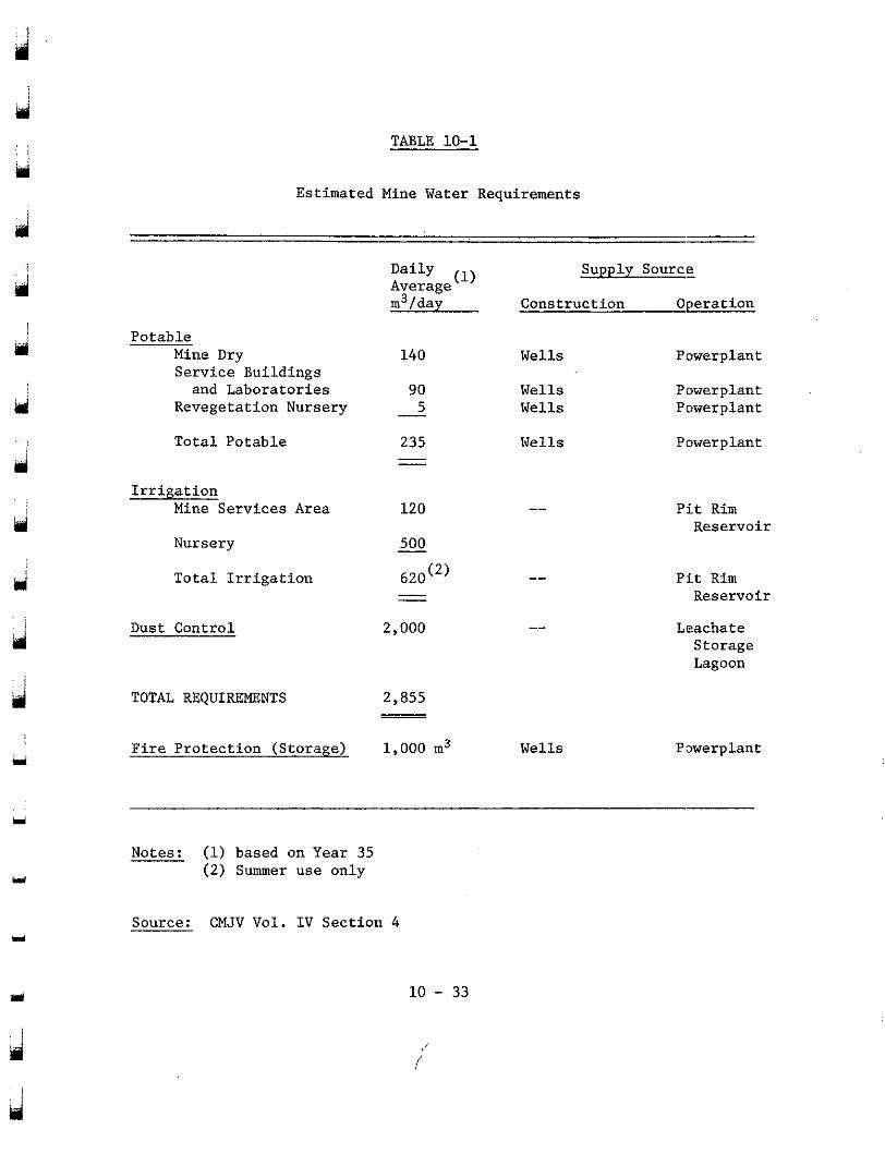
TABLE 10-1
Estimated Mine Water Requirements
Daily Average m3/day
(1) Supply Source
Construction Operation
Potable Mine Dry Service Buildings and Laboratories
Revegetation Nursery
Total Potable
140
90 5
235 - -
Wells
Wells Wells
Wells
Powerplant
Powerplant Powerplant
Powerplant
Irrigation Mine Services Area
Nursery
Total Irrigation
120
500
620") - -
2,000
" Pit Rim Reservoir
Pit Rim Reservoir
Leachate
Lagoon Storage
"
" Dust Control
TOTAL REQUIREMENTS 2,855 - -
1,000 m3 r Wells P'owerplant Fire Protection (Storage)
Notes: (1) based on Year 35 (2) Summer use only
L
Source: CMJV Vol. IV Section 4
10 - 33
19 i
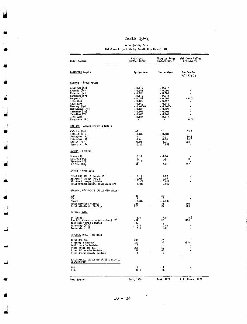
TABLE 10-2 mater Q v a l i w O D h
Hat Creek P r o j e c t W i n i n g F e a s i b i l i t y R e p o r t 1978
Hat Creek Surface Mater
T h q s O n RIWI Hat Creek Val ley Surface Mater Groundmter
system wean system Hean
< 0.017 < 0.005 G 0.005 < 0.010
0.005 < 0.022 < 0.010 < 0.00034 < 0.020 < 0.003 < 0.005
0.017
< 0.001 2.3 0.63 3.3 0.055
I 1
< 0.10
0.11 I .6
7.6
< 0.07 0.08
' 0.002 0.020
21 3
35 38
< 0.002
7.8 93
9 0.81 n.0
77 74
50 3
49 2
* I 11.1
one Sample Well V7B-72
' 0.03
0.05
5 9 . 8
59. I 24 .5
220
8
392
392 760
8.2 1470
1230
< 0.010 < 0.005 ' 0.005 ' 0.010 < 0.005 < 0.026 < 0.010 < 0.00040 < 0.020 < 0.003
0.005 ' 0.007
- A lka l i Ea r ths 6 M t a l s
57 0.002
19 4.0
20123 0.32
0.10 1.1 0.16
54
d - General
Boron (81 Chlor ide IC11 F luo r ide iF) Su l fa te lSO41
ANIONS . Nut r ien ts
Total Kjeldahl Ni t rogen (N) N i t r a t e N i t r o g e n lN03-N) N i t r i t e l l i t r o g e n (IIOZ-N) Total Orthophosphate PhoIPhOPUs (PI
0.05 0.19
' 0.w2 0.043
i ORGANIC, NONIONIC 6 CALCULA-
coo 21 9
< 0.002 224 226
PHYSICAL DATA
489 12
8.4
6 .6 1.5
348 342
6
278 281
d
Y
BIOCHEMICAL, DISSOLVED GASES 6 RELATED MEASUREMENTS
BOO 0.0.
Y
' 1 11.1
- oat. SDYlLePi Beak. 1978 Beak. 1978 H.A. S imnr . 1978
. . . . ."
10 - 34
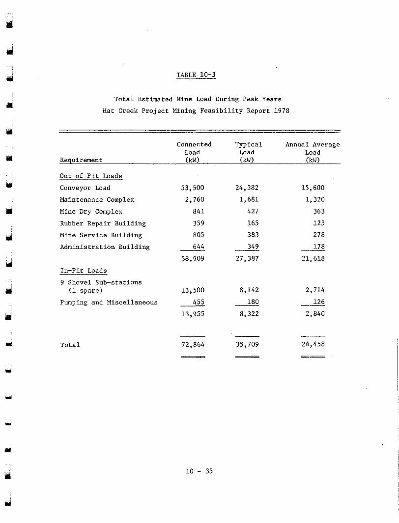
TABLE 10-3
id
d
d
i d
d i
Y
Total Estimated Mine Load During Peak Years Hat Creek Project Mining Feasibility Report 1978
Connected Typical Annual Average Load Load
Requirement (kW) (kW) (kW) Load
Out-of-Pit Loads
Conveyor Load Maintenance Complex Mine Dry Complex
Rubber Repair Building Mine Service Building Administration Building
In-Pit Loads 9 Shovel Sub-stations
(1 spare)
Pumping and Miscellaneous
Total
53,500 2,760
841
359 805 644
58,909
13,500
455 13,955
24,382 1,681 427 165 383 349
27,387
8,142 180
8,322
15,600 1,320 363 125 278 178
21,618 "
2,714
126 2,840 "
72,864 35,709 24,458 -__
-~ -~
Y
10 - 35
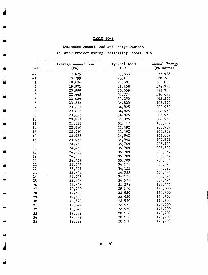
TABLE 10-4
Estimated Annual Load and Energy Demands
Hat Creek Project: Mining Feasibility Report 1978
ili
u
Y
Y
Year
-2 -1 1 2 3 4 5 6
8 7
9 10 11 1 2 13 14 15 16 1 7 18 19 20 2 1 22 23 24 25 26 27 28 29 30 31 32 33 34 35
Average Annual Load (kW) - 2,625
13,799 18,836 19,971
22,448 20,999
22,089 23,853 23,853
23,853 23,853
23,853 21,313 22,940 22,940 23,933 23,933 24,458 24,458 24,458 24,458 24,458 23,647 23,647 23,647 23,647 23,647 21,626 20,240
19,829 19,829
19,829 19,829 19,829 19,829 19,829 19,829
Typical Load (kW)
20,117 3,833
27,501 29,158 30,659 32,774 32,250 34,825 34,825 34,825 34,825 34,825 31,117 33,492 33,492 34,942 34,942 35,709 35,709 35,709 35,709 35,709 34,525
34,525 34,525
34,525 34,525 31,574 29,550 28,950 28,950 28,950 28,950 28,950 28,950 28,950 28,950
Annual Energy (MW hours)
120,702 22,988
165,006 174,948 183,954 196,644 193,500 208,950 208,950 208,950 208,950 208,950 186,702 200,952 200,952 209,652 209,652 208,254 208,254 208,254 208,254 208,254 634,525 634,525 631&, 525 634,525 634,525 1813,446 177,300 173,700 173,700 173,700 173,700 173,700 173,700 173,700 173,700
Y
10 - 36
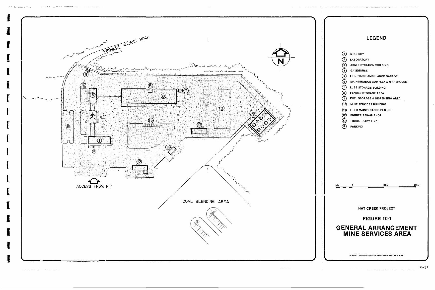
ACCESS FROM PIT
COAL BLENDING AREA
LEGEND
@ MINE DRY
@ LABORATORY
@ ADMINISTRATION BUILDING
@ GATEHOUSE
@ FIRE TRUCKIAMBULANCE GARAGE
@ ,MAINTENANCE COMPLEX & WAREHOUSE
@ LUBE STORAGE BUILDING
@ FENCED STORAGE AREA
@ FUEL STORAGE & DISPENSING AREA
@ MINE SERVICES BUILDING
@ FIELD MAINTENANCE CENTRE
@ RUBBER REPAIR SHOP
@ TRUCK READY LINE
@ PARKING
50m C"
0 loom zoom I
HAT CREEK PROJECT
FIGURE 10.1
GENERAL ARRANGEMENT MINE SERVICES AREA
SOURCE British Columbia Hydro and Power Authority
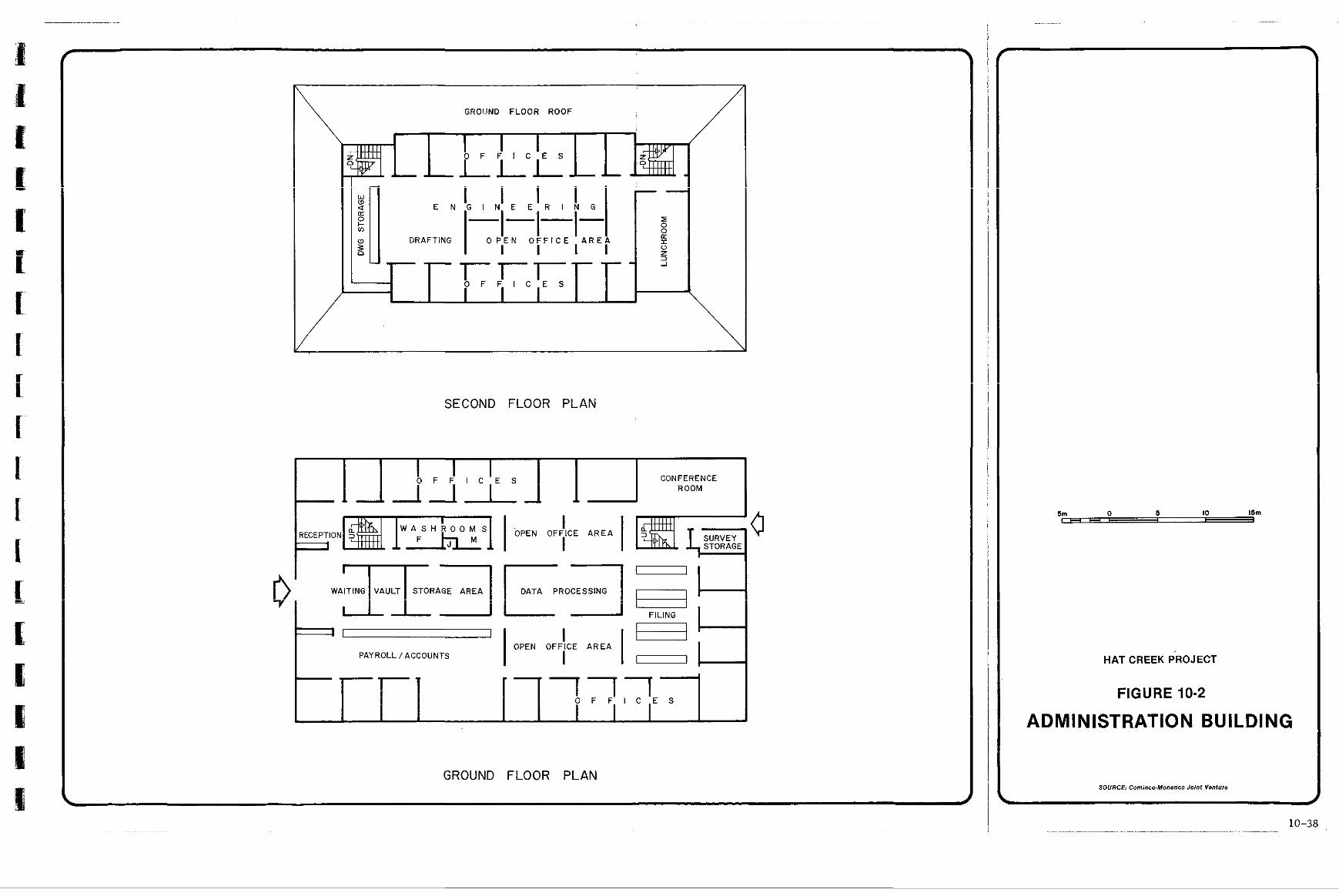
\ GROI!NO FLOOR ROOF
T-I"" O F F I C E S
i
\ SECOND FLOOR PLAN
I I I O F F I C E S CONFERENCE
ROOM
I I STORAGE
OFFICE AREA a 0' WAITING VAULT STORAGE 1 AREA I R O - l = 1-1
' I I I
PAYROLLlACCOUNTS OPEN OFFICE AREA
- "711 O F F I C E S
~ J
GROUND FLOOR PLAN
.
HATCREEKPROJECT
FIGURE 10-2
ADMINISTRATION BUILDING
SOURCE: Cominco-Monenco Joint Venture
b d
10-38
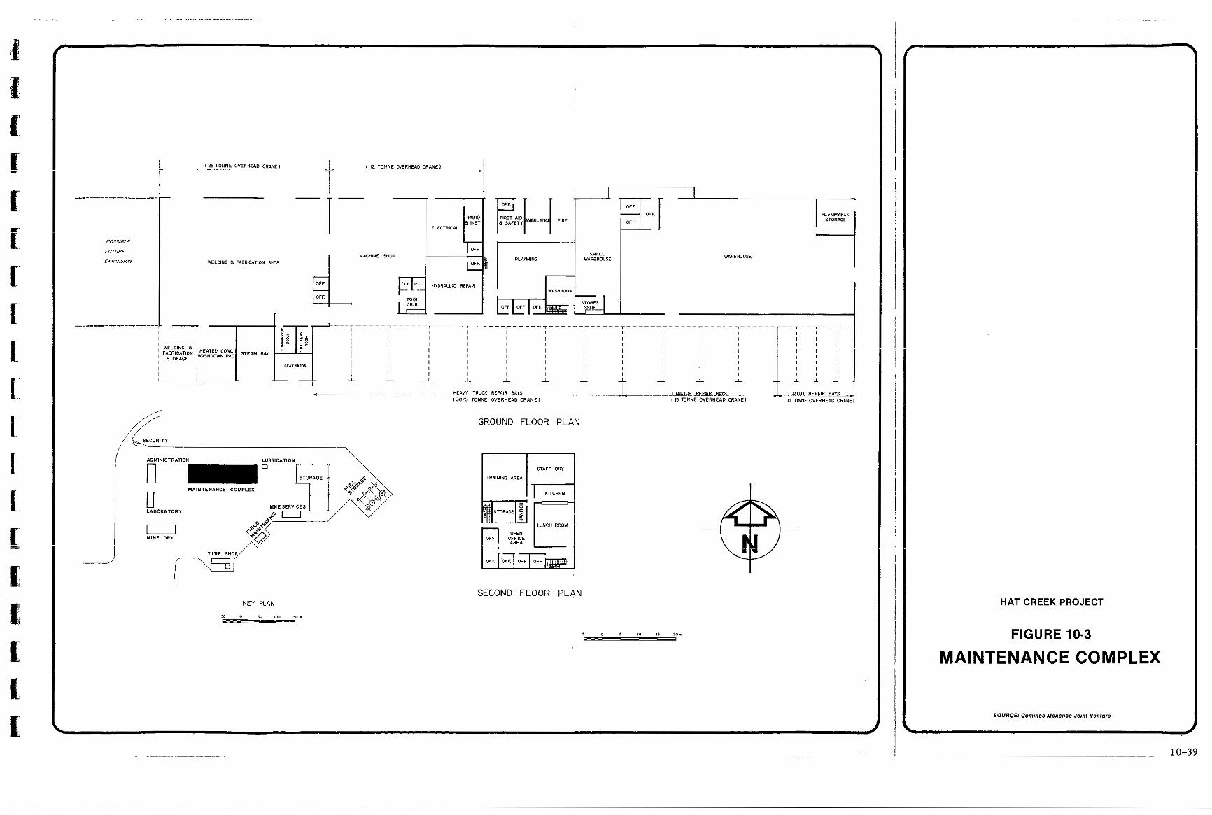
"""""""""_"
"""""""""."
i -
-1- -
I,
GROUND FLOOR PLAN
SECVRlT"
/ -' \
J SECOND FLOOR PLAN
KEY PLAN
I O D XI 800 lYrn
e e E
HAT CREEK PROJECT
FIGURE 10-3
MAINTENANCE COMPLEX
SOURCE: Cominco-Monenso Joint Venture
h I
10-39
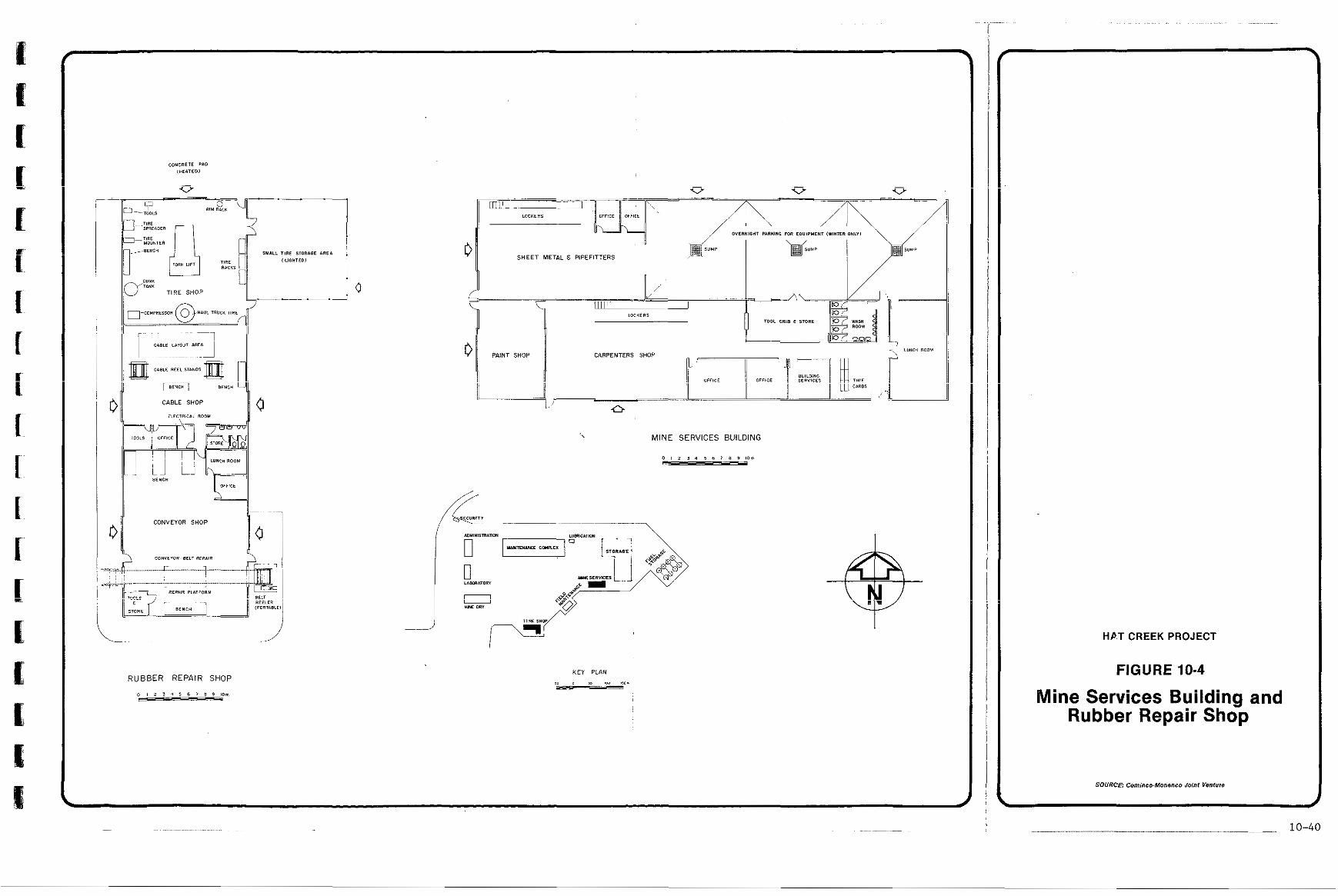
........
!
II
a I CONVEYOR SHOP j3
1 0
SHEET METAL 8 PiPEFlTTERS
n I
U
', MINE SERVICES BUILDING
" 7
i
b
- .............. ~ .......... ~~
HP.T CREEK PROJECT
FIGURE 10-4
Mine Services Building and Rubber Repair Shop
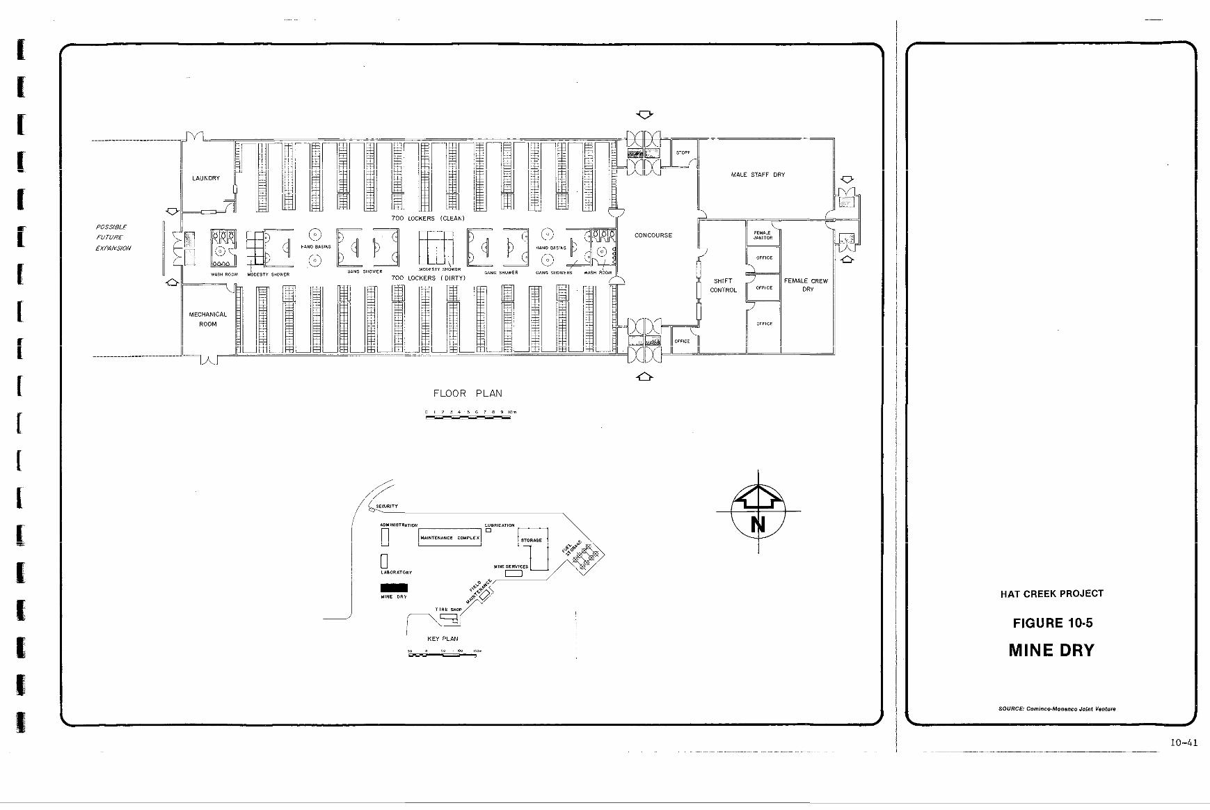
POSSIELE
FUTURE
EXPANSION
FLOOR PLAN
0 1 2 3 4 5 6 7 8 9 , O . ""
J HAT CREEK PROJECT
FIGURE 10-5
MINE DRY
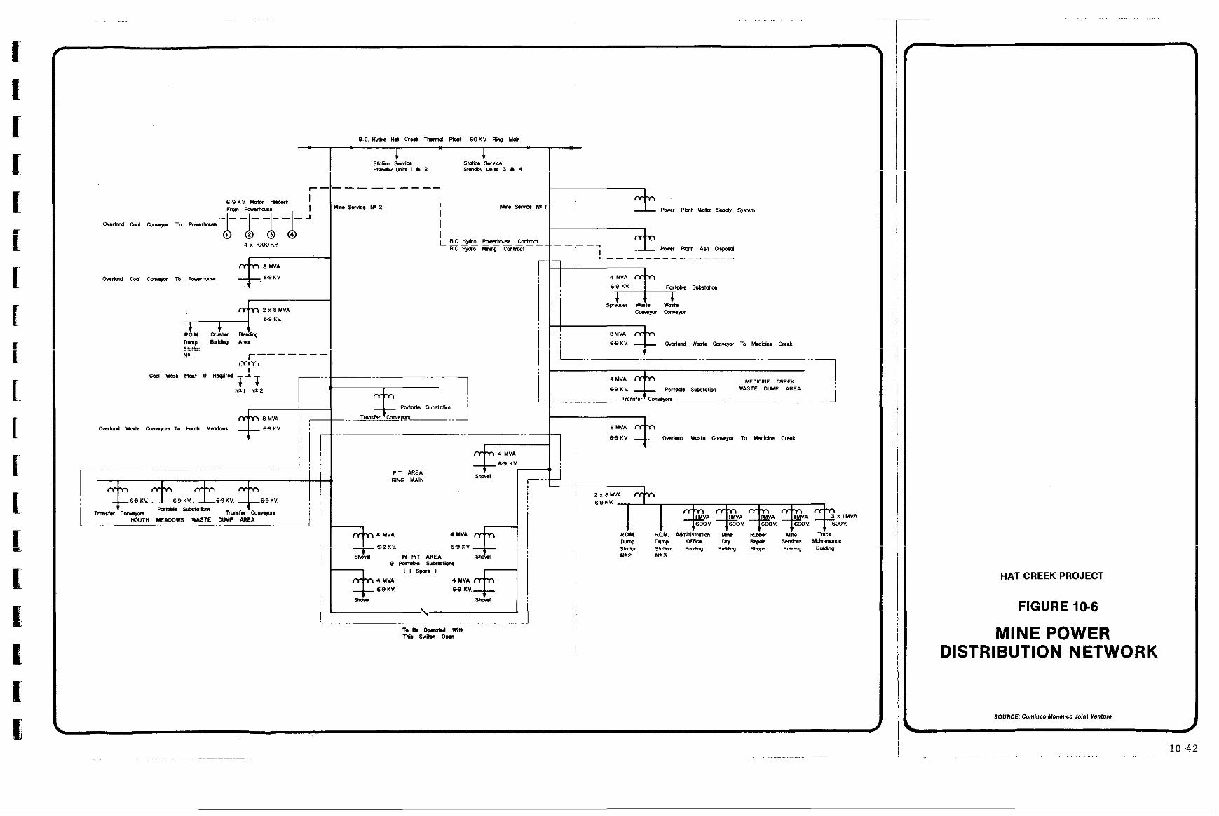
i
MEDICINE CREEK Pc.ld* S v b l l D t i WASTE DUMP AREA
.. .. .. i
HAT CREEK PROJECT
FIGURE 10-6
MINE POWER 1lSTRlBUTlON NETWORK
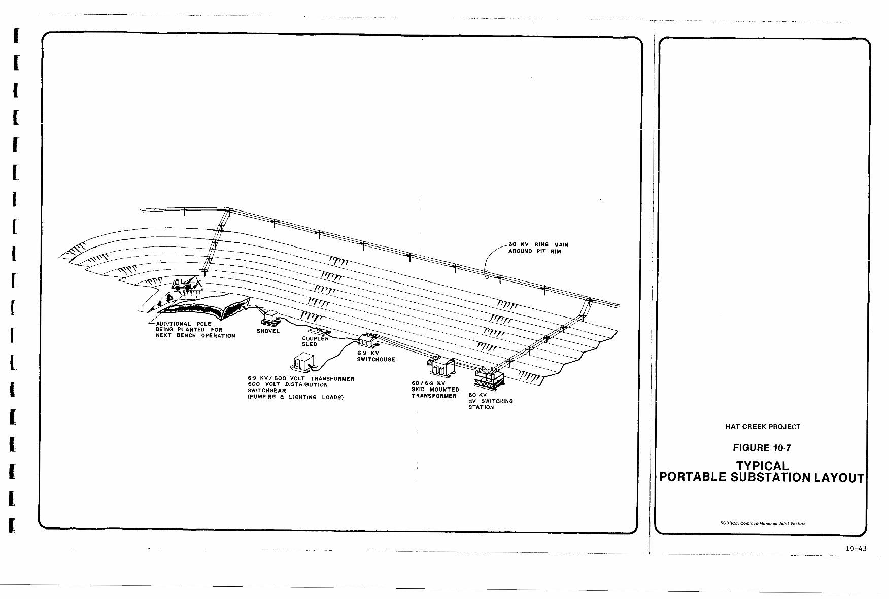
~ ~ ~ . . ~ ~~ __ ........ ........ . . . . . . . . . . . . . . . . .. . . . . . . . . . . . . . . . . . . . . . . . . . . . . . . . . .
STATION
..................
HAT CREEK PROJECT
FIGURE 10-7
TYPICAL 'ORTABLE SUBSTATION LAYOU7
SOURCE: Cominco-Manenco Joint Venture
i #
10-43
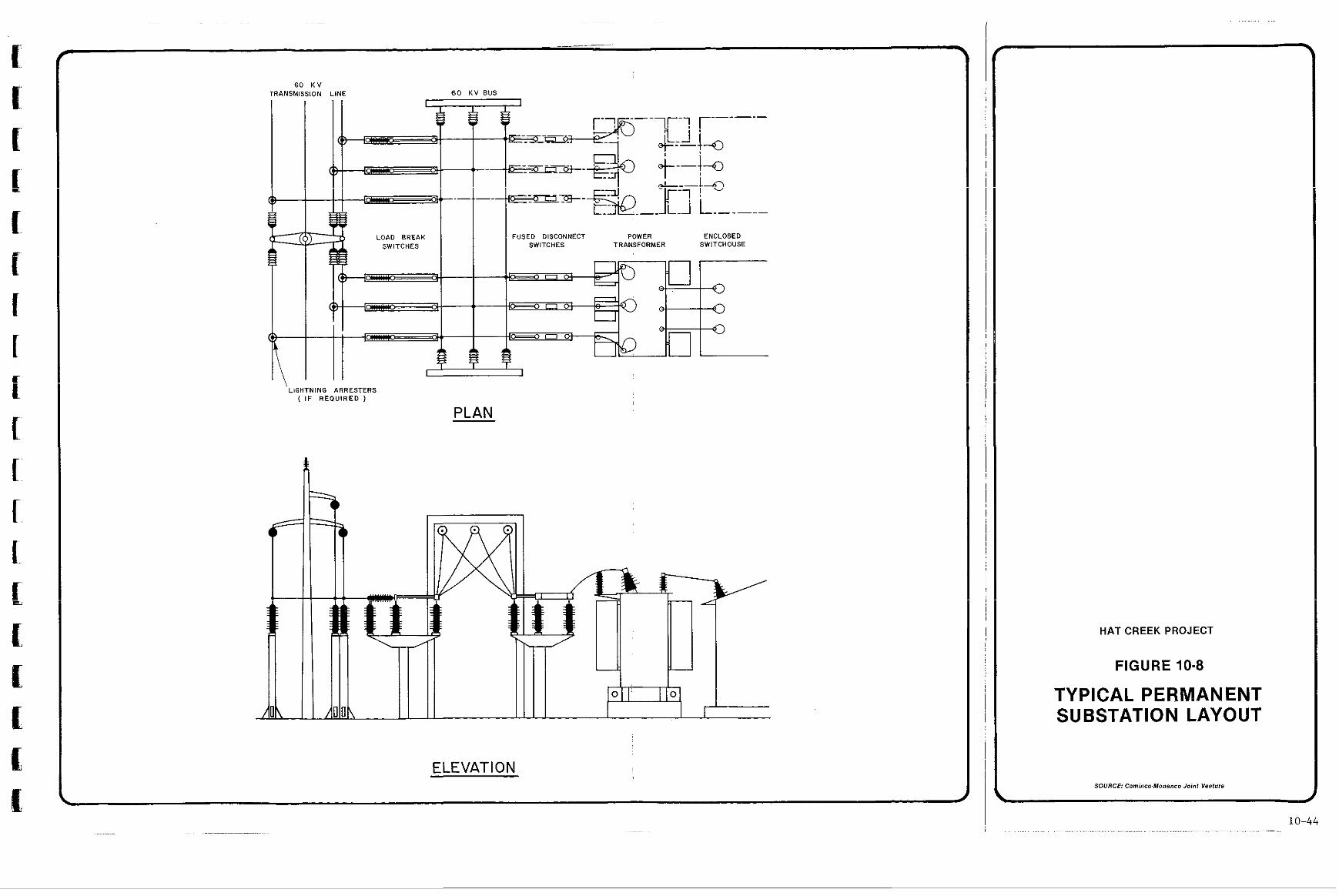
60 K V TRANSM
4-
3N L INE
1 1 60 K V BUS -
LOAD BREAK FUSED DISCONNECT POWER ENCLOSED SWITCHES TRANSFORMER SWITCHOUSE
I I LIGHTNING ARRESTERS
( IF R E Q U I R E D )
PLAN
1 ELEVATION
HATCREEKPROJECT
FIGURE 10-8
TYPICAL PERMANENT SUBSTATION LAYOUT
SOURCE: Cominco-Monenco Joint Venture
I I
10-44 .. ~ .... .... . . .... ....
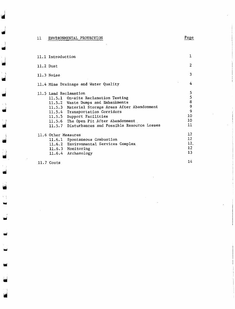
d 11 ENVIRONMENTAL PROTECTIOJ
d '>
d
d
11.1 Introduction
11.2 Dust
11.3 Noise
11.4 Mine Drainage and Water Quality
11.5 Land Reclamation 11.5.1 On-site Reclamation Testing 11.5.2 Waste Dumps and Embankments 11.5.3 Material Storage Areas After Abandonment 11.5.4 Transportation Corridors 11.5.5 Support Facilities 11.5.6 The Open Pit After Abandonment 11.5.7 Disturbances and Possible Resource Losses
11.6 Other Measures 11.6.1 Spontaneous Combustion 11.6.2 Environmental Services Complex 11.6.3 Monitoring 11.6.4 Archaeology
11.7 Costs
5 5
9 9 10 10 11
12 12 12. 12 13
14
a
mi
Y
d No. - ;LIST OF TABLES
d 11-1 Estimate of Areas Disturbed and Reclaimed by Year 35 15
d and Year 45
:LIST OF FIGURES 9
srl 11-1 Map of Reclamation b:y Year 45
mi
16
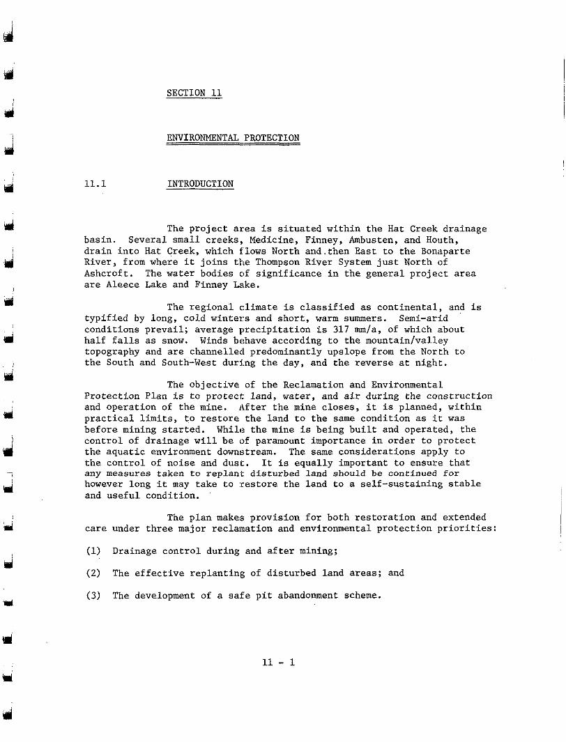
d
i
ti l
ri
d
1
11.1
SECTION 11
ENVIRONMENTAL PROTECTION
INTRODUCTION
basin. Several small creeks, Medicine, Finney, Ambusten, and Houth, d r a i n i n t o Hat Creek, which flows North and.then East to the Bonapar te River, from where it j o i n s t h e Thompson River System j u s t North of Ashcroft . The water bodies of s i g n i f i c a n c e i n t h e g e n e r a l p r o j e c t a r e a a r e Aleece Lake and Finney Lake.
The p ro jec t area i s s i t u a t e d w i t h i n t h e Hat Creek drainage
t y p i f i e d by long, cold winters and short , warm summers. Semi-arid
h a l f f a l l s as snow. Winds behave according to the mountain/vallay cond i t ions p reva i l ; ave rage p rec ip i t a t ion i s 317 mm/a, of which ;about
topography and are channelled predominantly upslope from the North to the South and South-West during the day, and t h e reverse a t n ight .
The r eg iona l c1imat.e is c l a s s i f i e d as con t inen ta l , and i s
The ob jec t ive of the Reclamation and Environmental Pro tec t ion P lan i s to p ro t ec t l and , water, and a i r dur ing the cons t ruc t ion and opera t ion of t h e mine. Af t e r t he mine c loses , i t is planned, within p r a c t i c a l limits, t o r e s t o r e t h e l a n d t o t h e same condi t ion as i t was before mining s tar ted. While the mine is b e i n g b u i l t and opera ted , the c o n t r o l of drainage w i l l be of paramount importance i n order t o p ro tec t the aquatic environment downstream. The same cons idera t ions apply to t h e c o n t r o l of no i se and dus t . It is equal ly impor tan t to ensure tha t any measures taken t o replant dis turbed land should be continued f o r however long it may t a k e t o : r e s t o r e the l a n d t o a se l f - sus t a in ing s t ab le and usefu l condi t ion .
care under three major reclamation and environmental protection priorit ies:
(1) Drainage control during and a f t e r mining;
(2) The e f f e c t i v e r e p l a n t i n g of dis turbed land areas; and
(3) The development of a s a f e p i t abandonment scheme.
The p l an makes p rov i s ion fo r bo th r e s to ra t ion and extended
11 - 1
11.2 DUST -
Initial studies of the air. quality impacts of the mine indicated a potentially serious problem with dust. A s a result,,. B.C. Hydro instructed the Mining Consultants (CMJV) to examine the problem and to devise suitable measures to enSure that the B.C. Pollution Control Branch guidelines for total suspended particulates. of 60 pg/m3
met. Results of this work, endorsed by the original air quality con- and 150 pg/m3 for annual and 24-hour averages respectively', cou1.d be
sultants, indicated that dust was indeed controllable, provided certain actions were undertaken. These proposed dust control measures, reviewed and accepted by B.C. Hydro, include both design changes and operating factors, for example:
- Blending piles: The present blending area was moved from its original position where the present mine services facilities are located. In addition, the area would be constructed "into" the adjacent hill to an e1evat:ion of
along the SW edge of the area, and the coal piles would 930 m, a protective dike to 950 m would be constructed
be suitably contoured to reduce erosion. Stacking out would be carried out with a telescopic chute on the boom
installed; conveyor. An effective water spray system would be
- The area stripped of surface soils will at all ti.mes be minimized to reduce erosion potential. In addition, stripping would be continued until non-friable (i.e. low- dusting potential) material was reached if possible;
- Binding agents would be used to control erosion where appropriate;
- Areas that would remain stripped for extended periods of time would be revegetated.
11 - 2
J
d ? 11.3 NOISE
d
d
Y
with those likely to arise f.rom operation of the mine. Findings show Existing sound levels have been measured and compared
that the Hat Creek Valley ma:y be affected by noise from the project, though not significantly.
40 dBA in the areas away from Highway 12. Adjacent to the highway, noise levels range from 44 to 51 dBA. By comparison, a soft whisper would produce a sound level of about 30 dBA, and a quiet wind through the trees would be around 50 dBA.
Present noise levels in the valley vary from about 30 to
Noise from construction would, of course, be transitory, whereas noise from the mine operation essentially constant throughout
heavy equipment moving in and around the pit, with intermittent additional the mine's productive life. The latter would stem principally from
noise from the coal stacker-reclaimer, conveyors and crushers. Only two of the five Hat Creek ranches are expected to be affected by construction activity noise. Maximum noise levels on these ranches would reach 47 dBA which is close to the 45 dBA typically set as a nighttime level by many communities.
may be affected by mining and coal preparation noise. The area involved The South-Western portion of the Bonaparte Indian Reserve
contains at present one dwelling with four to six residents. The two ranches nearest to the pit might experience intermittent noise levels up to 63 dBA; the next two, levels of between 45 and 49 dBA; and the two furthest away, levels of 41 co 42 dBA. As the natural background level is 35 to 40 dBA, the occasional level of noise from the mining operation is not expected to cause annoyance to anyone reasonably disposed.
m
11 - 3
ul
J
eri
11.4 MINE DRAINAGE AND WATER QUALITY
may be summarized by noting that all lagoons, diversions, ditches, and reservoirs linked with wetland and riparian habitats will be left intact
mining. Drainage control structures will be grass-seeded, and, where and revegetated wherever possible within the constraints imposed by
erosion or flow capacity is not involved, with a mixture of shrubs, trees, and grasses.
Drainage measures in so far as they affect reclamation
encountered during mining have been run to determine the concentrations of leachable materials. Based on these data and the water quality and hydrology of the water bodies to be affected by this project, the main drainage plan has been devised. Details are provided in Section 6 . Essential elements of the plan are:
Laboratory and field tests on materials which would be
All water suitable for simple diversion without any form'of treat- ment, such as Hat Creek, would be redirected around the project and returned to its natural downstream water course;
Run-off contaminated with sus.pended solid material would undergo sedimentation to reduce the concentration of suspended solids to less than 50 mg/L;
All water of unsuitable quality for discharge would be collected in
by spray evaporation on waste dumps. leachate pond and disposed of on site by re-use in dust control or
This drainage scheme would remain in service during the 10-year post-abandonment period to ensure that water quality values ,
downstream of the project would be maintained. The Hat Creek diversion
establish a suitable wetland habitat in the early stages of the project. scheme, headworks dam, and the pit rim dam would be developed to re-
All drainage ditches would be revegetated to reduce suspended solids contamination.
i
Y
11 - 4
LAND RECLAMATION -
m
11.5
11.5.1 On-site Reclamation Testing
to determine the properties of the waste materials as growth media and Both laboratory and on-site testing has been undertaken
to evaluate a variety of gras,s and legume species for revegetation at Hat Creek.
detailed on-site reclamation testing, making use of materials generated Initial 1abora.tory (greenhouse) studies were followed by
during the 1977 Bulk Sample Program. These latter tests have demonstrated most effectively that the revegetation of waste materials is feasible at Hat Creek consistent with B.C. Hydro proposed goals for reclamation. These may be summarized as follows:
(1) Short-term goals - Control of wind and water-borne erosion, - Aesthetics, - St:abilization of waste;
( 2 ) Long-term goals - Self-sustaining vegetation, - Suitable end use - mixed agriculture and wildlife.
The field tests comprised two major programs, one to
repose, and the other to examine the different materials and determine examine the revegetation potential of slopes at different angles of
their characteristics as growth media. All waste dumps associated with the 1977 Bulk Sample Program were also reseeded and provided facilities for further testing.
Slope Plots
Meadows and Medicine Creek to examine the revegetation potential on typical embankment material gravel-at Houth Meadows and till at Medicine Creek, at slopes of 2 2 , ?Ab,, and 30'. Half of each plot at Houizh
were selected to simulate as closely as possible climatic conditions to Meadows was covered with a thin layer of top soil. Aspect and aLtitude
be encountered at the Medicine Creek and Houth Meadows waste disposal embankments. Both areas were hydro-seeded with a single seed m i x in the Fall of 1977 and subsequently fertilised in the Spring of 1979.
Sloped reveget:ation test areas were constructed ai: Houth
0
11 - 5
Y
d
d
Growth assessments were made during the latter part of the 1978 and 1979 growing seasons and the plots examined for sigm of water-borne erosion. Results of these examinations have shown th.at there is essentially no difference in the success of vegetation e.stablish- ment on the materials without topsoil at the three slope angles; in all cases growth was satisfactory with a good mix of grass and legume.. Soil
were experienced during this period. On the topsoil-treated plots at erosion due to runoff was not apparent even though several thunderstorms
Houth Meadows, growth of seeded species was severely inhibited by the abundance and vigorous growth of weeds, the seeds of which were trans- ported to the site in the topsoil.
From the results of these studies it is concluded that embankment slopes at Houth Meadows and at Medicine Creek could be. con- structed to stable and rec1ai:mable slopes at least up to 30'.
Waste Material Test Plots
Seven waste materials were identified during the excavations of the 1977 Bulk Sample Program. Samples of these materials and of fly- ash from the Battle River Combustion Tests were set out in 15 m x: 15 m x
cover of topsoil and seeded in the Fall of 1977 with three different 1 m plots near Aleece Lake. Half of each plot was covered with a. thin
seed mixes of four species each. The soil characteristics of the mine waste materials suggest that they fall into essentially three categories, namely surficial materials such as colluvium (till), gravel, and baked clay; non-seam waste, gritstone (sandstone/claystone), and benton.itic clay; seam waste such as carbonaceous shale and waste coal. Each plot was fertilized during the Spring of both 1978 and 1979, based on recom- mendations from the B.C. Ministry of Agriculture following soils testing.
growing season to determine the success of revegetation based on seedling emergence and biomass production. A less comprehensive evaluation was
plots. The results of these studies may.be summarized as follows: conducted during 1979 to further monitor the progress of these test
(1) Revegetation of surficial materials such as colluvium (till),
Detailed vegetation monitoring was carried out after one
gravel, and baked clay can be readily achieved. Further, these soils are suitable for reclamation purposes without the addition of topsoil. This result is noteworthy: in the case of colluvium, both biomass production and seedling emergence were lower on. the topsoil-treated part of the plot. Plants were healthy and showed little sign of chlorosis. These results indicate that the m.ateria1s
media, may comprise any of these surface materials, gravel, colluvium selected for stripping, stockpiling and/or use as surface growth
(till), baked clay, and topsoil, either separately or in combination. The implication here is clearly that the separate stripping of topsoil has been shown to be unjustified in the presence Of suitable quantities of other surficial materials;
11 - 6
a
3
(2) Revegetation of non-seam mine waste, gritstone (sandstone/c:Laystone), and bentonitic clay proved to be more difficult to achieve in the
production of vegetation was poor; most plants exhibited leaf short term. In addition to low emergence success, the biomass
chlorosis. The physical. and chemical properties of these soils
moisture and nutrient imbalances. contribute to poor soil structure under extreme conditions of
The addition of topsoil proved beneficial although plants remained somewhat stunted. Subsequent 1979 observation showed some species of vegetation progressing well on the untreated gritstone. Never- theless, it is considered that a surface capping of surficial
materials; material would be required to satisfactorily revegetate these waste
(3) Seam waste was the most difficult of all materials tested to vegetate. However, the chemical cbaracteristics of these materials appear to be less of a deterrent than do their physical properties, particularly their dark colour resulting in excessive surface temperatures and the hydrophobic nature of the carbonaceous shale. A capping of surficial material would. be required for satisfactory reclamation.
Waste Dumps
seeded in late 1977. Piles a.t Trench C and unsatisfactory portions of
was applied to half of the uppermost dump at Trench A and to half of the the piles at Trench A were seeded in the Fall of 1978. Topsoil (15 cm)
dumps at Trench C. In addition, water retention furrows were constructed across the dump fall line in an attempt to improve moisture retention on the dump surface.
Waste material. stockpiles from trenches A and B were
The results on. these dumps confirm the results at Aleece
while bentonitic clay and gritstone show less success. Germinatj.on in Lake and the slope plots. Gravels and baked clay are readily revegetated,
topsoil was substantially successful than germination in baked clay. Further, the dramatic growth in the water retention furrows constructed in bare carbonaceous shale and bentonitic clay clearly
at Hat Creek, where the annual precipitation totals only 317 mm. identifies the lack of moisture as a most important factor in revegetation
Vegetation Species
been tested in these revegetation trials. The species were selected on the basis of their known characteristics and adaptation to the soils and climatic conditions at Hat Creek, To ensure that the species were both viable and available, only agronomic species were considered. Seed mixes of four and five species were devised and, in some instances, species were used individually.
I n total 16 different species of grass and legume have
11 - 7
d
rl
ri
U
n
Results of these field tests have identified several species which could be used for reclamation purposes at Hat Creek. Among the grass species the following perennial grasses show excellent potential: Crested Wheatgrass (Nordan), Streambank Wheatgrass (Sodar), Slender Wheatgrass, Tall Whea.tgrass (Altar), and Smooth Bromegrass (Manchar). Fall ryegrass proved to be an excellent species for rrhort-
particularly tall-growing and. vigorous, it is suspected of inhibiting term (1 year) revegetation. However it is an annual, and because it is
the growth of other perennial. species with which it was seeded. As a result, its use would be rest.ricted to those occasions where short-term revegetation - for example, for dust control - is required.
(Drylander) and Sainfoin (Mehose) have proved most successful. Double- cut red clover and white clover, a biannual, showed lesser success, but may be useful as minor specie.s in seed mixes. All legumes performed better when competition from other plants was absent.
Several legumes have been tested. Of these Alfalfa
and related areas at Hat Creek would be largely based on those identified above. Mixes of approximately five species, of which three would be grasses, would be selected an.d seeded, mostly by harrow-seeding methods. Only in areas too steep for h.arrow-seeding would hydro-seeding be used. Due to the low precipitation, seeding would be carried out in 1at:e Fall
being favoured in order that maximum use could be made of moisture (September-November) or early Spring (April-May), the former period
accumulating over the Winter months. Legumes may benefit from early Spring seeding to reduce losses by Winter kill.
The selection of species for revegetation of waste dumps
In addition to these agronomic species, native shrubs and
need to be transplanted and/or propagated in the project nursery. forbs considered essential in the reclamation of wildlife habitat:s would
11.5.2 Waste Dumps and Embankments
Rapid revegetation of embankments and waste dumps will stabilize exposed surfaces against erosion. Temporary reclamation will be carried out on all areas of dump surfaces left inactive for a number of years. Retaining embankments will be constructed in lifts whi.ch allow for long-term reclamation concurrently with construction. Waste dump surfaces will be reclaimed as soon as the final surface elevation is reached.
Y
mi 11 - 8
use comparable with adjacent lands at similar elevation. Topography and diversity of native species similar to pre-mining conditions cannot be duplicated, but reclamation of waste dumps will be designed to provide a revegetated, self-sustaining, stable surface composed of materials similar to, or better, than those of adjacent lands. Presently, land in the area is used for mixed wi.ldlife and agricultural (mostly ranching) purposes. It is proposed to revegetate waste dump surfaces to a similar land use as now exists.
Waste dumps wi.11 be concurrently revegetated to an end
As a result of on-s~ite testing as described in 11..5.1, it is proposed to strip and to stockpile surface soils only from those
Allowance has been made to cover waste dumps comprised of seam or non- areas where the depth of the soil allows for economic extraction methods.
precise depth required would be established through further on-site seam material with approximately 1 m of surficial material, though the
material, would be temporarily revegetated to prevent erosion and testing. Those areas exposed by stripping, and stockpiles of surficial
dusting .
11.5.3 Material Storage Areas After Abandonment
The coal stock.pile and blending area will be level-led and sloped to harmonize with the surrounding topography. The contoured
overburden, and seeded. surfaces will then be covered with a buffering medium of non-sodic
The surficial soil stockpiles will decrease progressively as the soil is spread over disturbed lands throughout the mine site. The remains will be levelled, sloped to blend in with the surrounding topography, and seeded.
Y
11.5.4 Transportation Corridors Y
ui These take up about 4% of the disturbed land withi.n the mine area. Before construction, suitable surface soils will be removed and stockpiled. Inactive sections will be seeded as soon as possible after construction, to mini2ize dusting and erosion. Cut and fi1.l slopes will be graded to 26 and seeded. Trees and brush will be removed from rights-of-way to reduce any fire hazard.
11 - 9
.P
During the years immediately following shutdown of the mine, conveyors, transmission line!;, and culverts will be dismantled and removed. Wherever possible, corridors will be re-sloped to blend in with the surrounding topography. All roads (except main access roads) will be ripped to relieve compaction, and seeded. Water bars will be constructed on slopes with a potential for rill erosion.
11.5.5 Support Facil:=
The present site has a poor quality rating in terms of land use, and the reclamation measures will be designed to enhance the value of the disturbed land.
During construction, the buildings will be screened from the main access roads by a belt of trees, not merely to improve the appearance, but to prevent dusting. 'No significant reclamation will take place until after the mine doses.
for alternative uses will be dismantled, sold, and levelled to their During the years following closure, buildings not retained
foundations. Any areas littered will be cleared during the mine clean-up operation. Most of the Mine Services Area will then be ripped to relieve compaction, covered with 15 'to 30 cm of soil, and seeded. Where practical, slopes will be regraded to b.Lend in with the surrounding topography. Where surface materials are unsuitable for plant growth, a suitable dbpth of overburden will be placed before soil coverage and seeding.
11.5.6 The Open Pit After Abandonment
minimize the potential hazard to human life, livestock, and wildlife, of a large void constructed of weak material. A proposal to flood the pit and convert it into a la'ke was explored but rejected on the grounds of poor stability of the surrounding ground, the anticipated poor quality of the pit water, and the costly and possibly irrevocable nature of a decision that would.make it virtually impossible to re-open the pit at
will remain. some future time in order to extract the substantial coal reserves which
Considerable :planning has gone into measures designed to
11 - 10 1
benches (about 115 ha) from & 5 O t o 26' to p rovide a safer perime.ter and lessen the v i sua l impact . N o re-sloping w i l l be done below t h i s level. A f t e r r e - s l o p i n g , f e r t i l i z e r and seed w i l l be ae r i a l ly b roadcas t on a l l p i t benches. Germination i s expec ted to t ake p lace readi ly on those po r t ions which cons i s t of non-sodic glacio-fluvial and g l a c i a l t:L11 overburden, less r e a d i l y on t:hose composed of s a l i n e s l i d e d e p o s i t s ,
and s l i d e areas may be expect:ed t o creep and t o slump i n t o t h e p i t . s o d i c s i l t s t o n e s , c l a y s t o n e s , and coal . I n time, revegetated overburden
The plan adopted provides for re-s loping the top . three
A p r o t e c t i v e f e n c e t o restrict access w i l l surround the p i t pe r ime te r and those areas t o t h e South-West which may be suscep t ib l e t o f a i l u r e . Trees w i l l be p lan ted a t se l ec t ed po in t s on the per imeter t o s c r e e n t h e p i t .
11.5.7 Disturbances and Possible Resource Losses
been disturbed by Year 35. Ily Year 45, however, a l l but 571 ha will have been restored. This represents less than 1% of t h e Hat Creek Watershed. O f t h i s , 80 ha include t ransportat ion corr idors , lagoons, r e s e r v o i r s , and remaining f a c i l i t i e s f o r long-term environmental monitoring.
which would remain as is so as not t o p rec lude t he f u r t h e r economic The remaining 491 ha r ep resen t s t h e lower portions of t h e p i t i t se l f
e x t r a c t i o n of the coal resource. Table 11-1 shows the d e t a i l s of a r eas d is turbed and those reclaimed by Years 35 and 45. The a r e a s t o b e reclaimed by Year 45 are shown i n F i g u r e 11-1.
A maximum of 1.,931 ha w i l l , a t one time or another, have
The only resources l ike ly to be bur ied o r o therwise a l i e n a t e d by the mine are aggregate (sand and gravel), and some : l ime- s tone depos i t s . The lat ter are ins igni f icant in compar ison wi th the l a rge r e se rves ' o f l imes tone i n areas immediately adjacent. And much of the aggregate excavated during construct ion w i l l be s tockp i l ed fo r future use.
11 - 11
Y
Y
11.6
11.6.1
OTHER MEASURES
Spontaneous Combustion
combustion of loose and compacted coal piles. These showed that with a temperature rise of 60'-70°C, fires began in piles of loose, uncompacted coal in between four to eight weeks, Precautionary measures will. be required to crush and compact the coal in such stockpiles. The problem
piles. Monitoring of coal-pile temperature will be required. can be minimized by the restacking time coal spends in uncompacted
Tests were carried out in 1977 to determine the spontaneous
11.6.2 Environmental Services Complex
Plan will be under the control of staff housed in the Environment:al Services Complex, which is equipped with modern laboratory facilities. The plant propagation nursery forms part of the complex.
All aspects of the Reclamation and Environmental Protection
11.6.3 Monitoring
Geotechnical monitoring of pit slopes, waste dumps, and slide areas will continue during mining to ensure operational safety as well as to develop reliable a.bandonment procedures. The temperature of
bustion. The quality of soil. and buffer material will be monitored to carbonaceous material will be monitored to prevent spontaneous com-
ensure adequate depth of uncontaminated growth medium. In addition, the quantity, quality, regenerati.on potential, nutrient and metal content of vegetation grown on disturbed land will be monitored to determine if the vegetation is self-sustaining and satisfactory f o r livestock and wildlife consumption.
compliance with PCB objectives. Seepage and leachate flows will be monitored in groundwater wells; also the discharge from all treatment
Surface and groundwater will be monitored to ensure
11 - 12
will be to segregate sediment-laden water, clear water, waste water, and lagoons. Broadly speaking, .the primary objective of water monitoring
other surface flow, treat those parts which may require it, and discharge the rest.
and dustfall levels. Air quality would be monitored for suspended particulate
mine closes. Monitoring wi:ll continue for at least 10 years after the
11.6.4 Archaeology
A conservation strategy will be adopted to preserve significant heritage resources discovered during the process of excavation.
will be sufficient time to complete an inventory of such heritage resources A5 scraper work will be carried on progressively during mining, there
a5 may be uncovered.
3
Y
11 - 13
Y
Y
Y
3
Hi i
ui
11.7 - COSTS
amount t o $40 mi l l ion . This : inc ludes the cap i ta l cos t o f a l l bui ldings, f i e l d equipment, seed and plant stock. Operating costs include staff and a l l materials requ i r ed t o c a r r y out the plan.
The es t imated cap i ta l and opera t ing costs of t he p l an
per iod, 35 yea r s of production, and a 10-year post-production period The reclamation costs span a 6-year pre-production
devoted to reclamation, which w i l l cost approximately $7 million.
The Environmental Protect ion Sect ion of this r e p o r t is based upon Volume V of CWV's J u l y 1978 r epor t en t i t l ed "Mine Reclamation and Environmental Protection". It has not been a d j u s t e d t o r e f l e c t c h a n g e s i n t h e 1 9 7 9 Mining P lan , which are considered t o b e i n s i g n i f i c a n t .
11 - 14
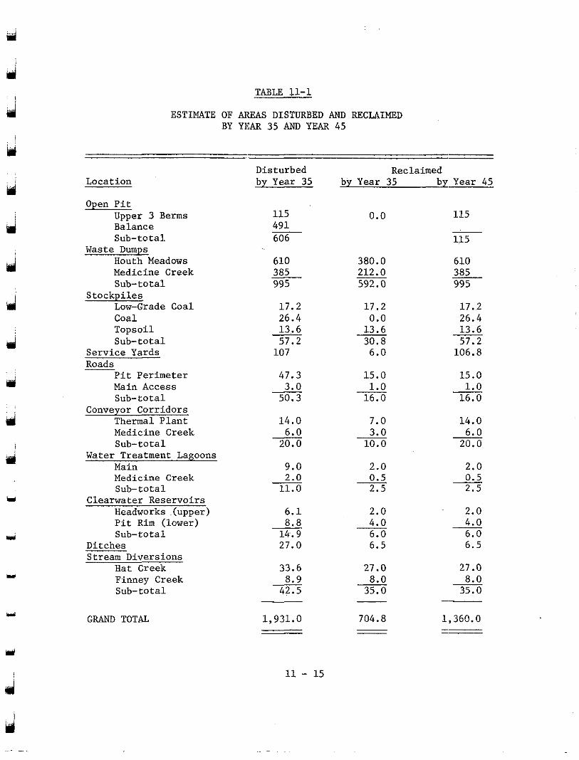
rrl
Y
I
TABLE 11-1
ESTIMATE OF AREAS DISTURBED AND RECLAIMED BY YEAR 35 AND YEAR 45
Location
Open Pit Umer 3 Berms Biiance Sub-total
Medicine Creek Houth Meadows
Sub-total
Low-Grade Coal Coal Topsoil Sub-total
Waste DUmpS
Stockpiles
Service Yards Roads
Pit Perimeter Main Access Sub-total
Conveyor Corridors Thermal Plant Medicine Creek Sub-total
Water Treatment Lagoons
Medicine Creek Main
Sub-total Clearwater Reservoirs
Headworks .(upper) Pit Rim (lower) Sub-total
Ditches Stream Diversions
Hat Creek Finney Creek Sub-total
GRAND TOTAL
Disturbed by Year 35
115 491 606 -
610 385 995 - 17.2 26.4 13.. 6 57.2 107
47.3
50.3 3.0
14.0 6.0 20.0
9.0
11.0 2.0
6.1 8.8 14.9 27.0
33.6 8.9 42.5
-
-
-
1,931.0
by Year 35 by Year 45 Reclaimed
0.0 115 - 115
380.0 212.0 592.0
610 385 995
17.2 17.2
13.6 0.0
30.8
26.4 13.6 57.2
6.0 106.8
15.0 1.0 16.0
15.0 1.0 16.0
7.0 14.0
10.0 3.0
20.0 6.0
2.0 2.0 0.5 2.5
0.5 2.5
2.0 2.0 4.0 - 6.0 6.5
4.0 6.0 6.5
27.0 27 .O
35.0 8.0
35.0 8.0
- ”
704.8 1,360.0 - ___ ” __
Y
11 - 15
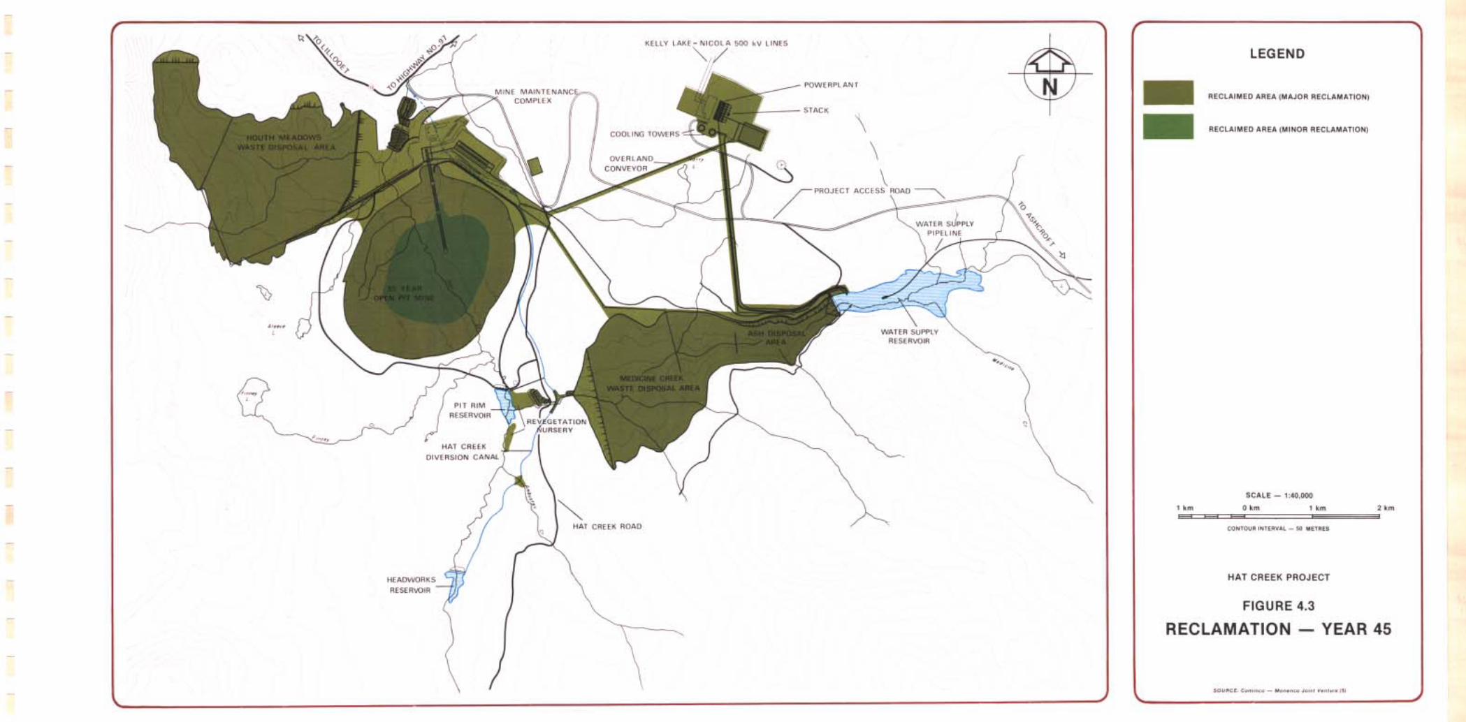
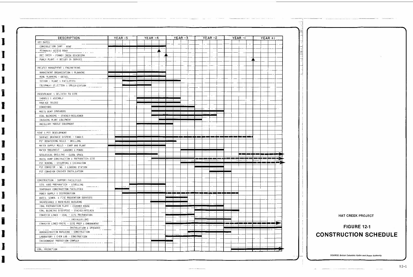
DESCRIPTION I YEAR -5 YEAR -4 YEAR - 3 YEAR -2 YEAR - I Y E A R + I KEY OATES I
CONSTRUCTION CAMP ~ M INE I
I I I I I I PERMANENT ACCESS ROAO + I HAT CREEK - F INNEY CREEK DIVERSION
POWER PLANT . I BOILER I N SERVICE
I I 4
!
I I I I I PROCUREMENT i OELIVERY TO S I T E I
CRUSHING PLANT EOUIPMENT
ANCILLARY MOBILE EOUIPMENT
MINE 9 P I T DEVELOPMENT I 1
SURFACE DRAINAGE SYSTEMS - CANALS
P I T OEWATERING WELLS - D R I L L I N G II ! I I I I I I I I I I I I I I I I I I I I I I
1 I I I
WATER SUPPLY WELLS - CAMP AND PLANT
WATER TREATMEN1 ~ LAGOONS S PONDS
GEOLOGICAL DRII-LING - CLOSE SPACE I 111111111119 """""- " ""
I
U COAL PRODUCTION I I I I I I I I I I
I
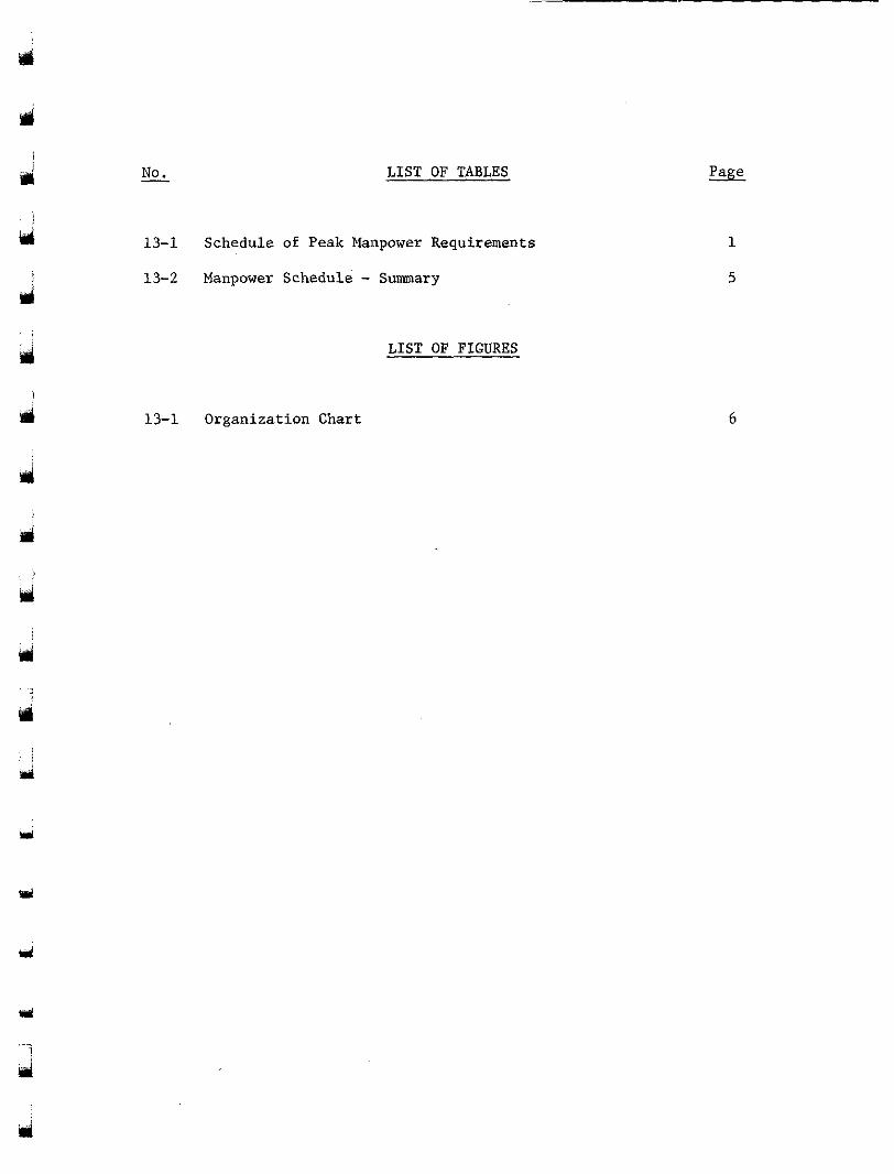
d
a
M
I No. LIST OF TABLES
13-1 Schedule of Peak Manpower Requirements
13-2 Manpower Schedule - Summary
LIST OF FIGURES
13-1 Organization Chart
1
5
6
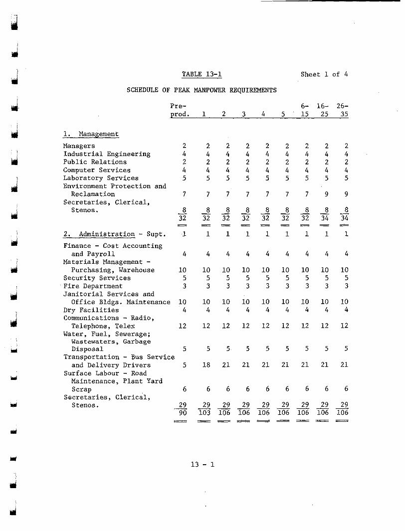
d
TABLE 13-1 Sheet 1 of 4
SCHEDULE OF PEAK MANPOWER REQUIREMENTS
Pre- 6- 16- 26- prod. 1 2 3 4 5 15 25 35
1. Management Managers 2 2 2 2 2 2 2 2 2 Industrial Engineering 4 4 4 4 4 4 4 4 4 Public Relations 2 2 2 2 2 2 2 2 2 Computer Services 4 4 4 4 4 4 4 4 4 Laboratory Services 5 5 5 5 5 5 5 5 5 Environment Protection and Reclamation 7 7 7 7 7 7 7 9 9
ri
d
d
d . .
i
m
Secretaries, Clerical, Stenos. - a - 8 8 8 8 8 8 8 8 -.
32 32 32 32 32 32 32 34 34 """
- - - - - - - - - - - - - - - - - - 2. Administration - Supt. 1 1 1 1 1 1 1 1 1 Finance - Cost Accounting and Payroll 4 4 4 4 4 4 4 4 4
Materials Management - Purchasing, Warehouse 10 10 10 10 10 10 10 10 10
Security Services 5 5 5 5 5 5 5 5 5 Fire Department 3 3 3 3 3 3 3 3 3 Janitorial Services and Office Bldgs. Maintenance 10 10 10 10 10 10 10 10 10
Dry Facilities 4 4 4 4 4 4 4 4 4 Communications - Radio, Telephone, Telex 12 12 12 12 12 12 12 12 12
Water, Fuel, Sewerage; Wastewaters, Garbage Disposal 5 5 5 5 5 5 5 5 5
and Delivery Drivers 5 18 21 21 21 21 21 21 21
Maintenance, Plant Yard ScraD 6 6 6 6 6 6 6 6 6
Transportation - Bus Service Surface Labour - Road
~~
Secretaries, Clerical, Stenos. __ 29 """" 29 29 29 29 29 29 29 29
90 103 106 106 106 106 106 106 106
13 - 1
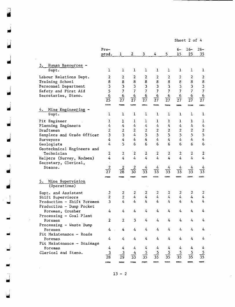
rsi i Sheet 2 of 4
Pre- prod. 1 2 3 4 5 15 25 35
6- 16- 26-
ui
d
d
d i
j Y
3. Human Resources - Supt. 1 1 1 1 1 1 1 . 1 1
Labour Relations Dept. 2 2 2 2 2 2 2 2 2 Training School 8 8 8 8 8 8 8 8 8 Personnel Department 3 3 3 3 3 3 3 3 3 Safety and First Aid 5 7 7 7 7 7 7 7 7 Secretaries, Steno. - 6
25 27 27 27 27 27 27 27 27 6 6 6 6 6 6 6 6
4 . Mine Engineering - Supt. 1 1 1 1 1 1 1 1 1
Pit Engineer 1 1 1 1 1 1 1 1 1 Planning Engineers 4 4 4 4 4 4 4 4 4 Draftsmen 2 2 2 2 2 2 2 2 2 Samplers and Grade Officer 3 3 4 5 5 5 5 5 5 Surveyors 4 4 4 4 4 4 4 4 4 Geologists 4 5 6 6 6 6 6 6 6 Geotechnical Engineers and Technician 2 2 2 2 2 2 2 2 2
Helpers (Survey, Rodmen) 4 4 4 4 4 4 4 4 4 Secretary, Clerical, S tenos .
5 . Mine Supervision (Operations)
Supt. and Assistant
Production - Shift Foremen Shift Supervisors
Production - Dump Pocket
Processing - Coal Plant Processing - Waste Dump
Pit Maintenance - Roads Pit Maintenance - Drainage Clerical and Steno.
Foremen, Crusher
Foremen
Foremen
Foremen
Foremen
- 27 28 30 33 33 33 33 33 33
2 2 4 4 4 4 4 4 2 - - - - - - - -
2 2 2 2 2 2
2 4 4 4 4 4 4 4 2 2 2 2
3 4 4 4 4 4 4 4 4
4 4 4 4 4 4 4 4 4
2 2 3 4 4 4 4 4 4
4 . 4 4 4 4 4 4 4 4
4 4 4 4 4 4 4 4 4
4 4 4 4 4 4 4 4 4 3
28 29 33 35 35 35 35 35 35 3 4 5 5 5 5 5 5 - """"
Y
13 - 2
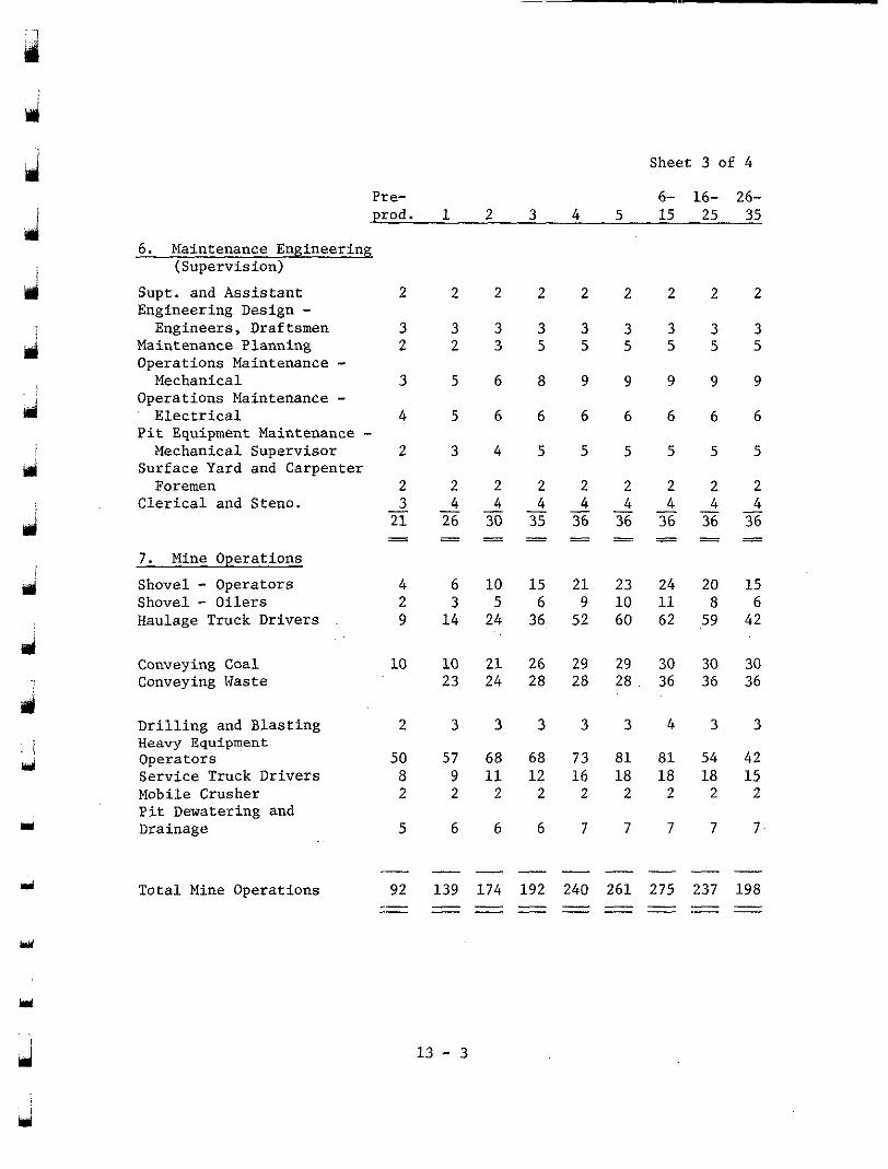
Sheet 3 of 4
6- 16- 26- 4 5 15 25 35 .prod.
Pre-
43 1 2 3
6 . Maintenance Engineering (Supervision)
Y i
2 2 2 2 2 2 2 2
3 3 3 3 3 5 5 5 5 5
9 9 9 9 9
6 6 6 6 6
5 5 5 5 5
2 2 2 2 2
Supt. and Assistant 2 Engineering Design - Engineers, Draftsmen 3
Maintenance Planning 2 Operations Maintenance - Mechanical 3
Operations Maintenance - Electrical 4
Pit Equipment Maintenance - Mechanical Supervisor 2
Surface Yard and Carpenter Foremen 2
Clerical and Steno. - 21
3
- - 7 . Mine Operations Shovel - Operators 4 Shovel - Oilers 2 Haulage Truck Drivers 9
3 3 3 2 3 5 ul 5 6 8
5 6 6
3 4 5
2 2 2
d
Y
- - - - - - - - 26 30 35 36 36 36 36 36
4 4 4 4 4 4 4 4
d " " _ " " _ 6 10 15 3 5 6
1 4 24 36,
21 23 24 20 15 9 10 11 8 6
52 60 62 59 42
d
Conveying Coal Conveying Naste
10 10 2 1 26 29 29 30 30 30 23 24 28 28 2 8 . 36 36 36
J
Drilling and Blasting Heavy Equipment Operators
Mobile Crusher Service Truck Drivers
Pit Dewatering and Drainage
2
50 8 2
5
3 3 3 3 3 4 3 3
57 68 68 73 81 81 54 42 9 11 1 2 1 6 18 1 8 18 15 2 2 2 2 2 2 2 2
6 6 6 7 7 7 7 7
- 139 174 192 240 261 275 237 198 - - - - - - " - ""
92 " "
gi Total Mine Operations
Y
1 3 - 3 ui
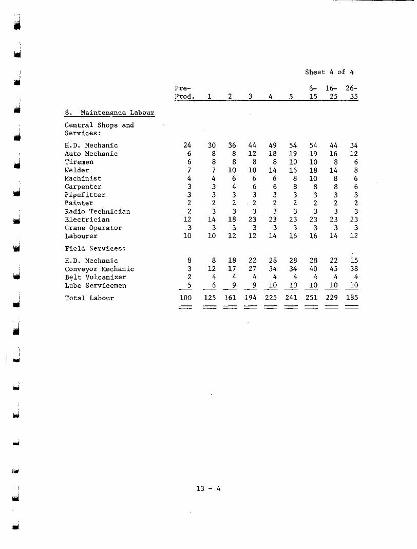
Y
d
ui
rrl
8 . Maintenance Labour
Cent ra l Shops and Serv ices :
Auto Mechanic H.D. Mechanic
Welder Tiremen
Machinist Carpenter P i p e f i t t e r Pa in t e r
E l e c t r i c i a n Radio Technician
Labourer Crane Operator
Field Services:
H.D. Mechanic Conveyor Mechanic B e l t Vulcanizer Lube Servicemen
To ta l Labour
Pre- ]?rod. "
24 6 6
4 7
3 3
2
1 2 2
1 0 3
8 3 2 5
100 - - -
Sheet 4 of 4
6- 16- 26- 1 2 3 4 5 1 5 2 5 3 5
30 36 44 49 54 8 8 1 2 1 8 1 9 8 8 8 8 1 0 7 1 0 1 0 1 4 1 6 4 6 6 6 8 3 4 6 6 8 3 3 3 3 3 2 2 2 2 2
1 4 1 8 23 23 23 3 3 3 3 3
54 1 9 1 0
1 0 18
8 3 2
23 3
44 34 16 12
1 4 8 8 6
8 6 8 6 3 3 2 2
23 23 3 3
10 1 2 1 2 1 4 1 6 1 6 1 4 1 2 3 3 3 3 3 3 3 3
8 1 8 22 28 28 28 22 15 1 2 1 7 27 34 34 40 45 38
4 4 4 4 4 4 4 4 6 9 9 1 0 1 0 1 0 1 0 1 0
125 161 194 225 241 251 229 185 - - - - - - - - - - - - - - - - - - - - - - -
1 3 - 4
d
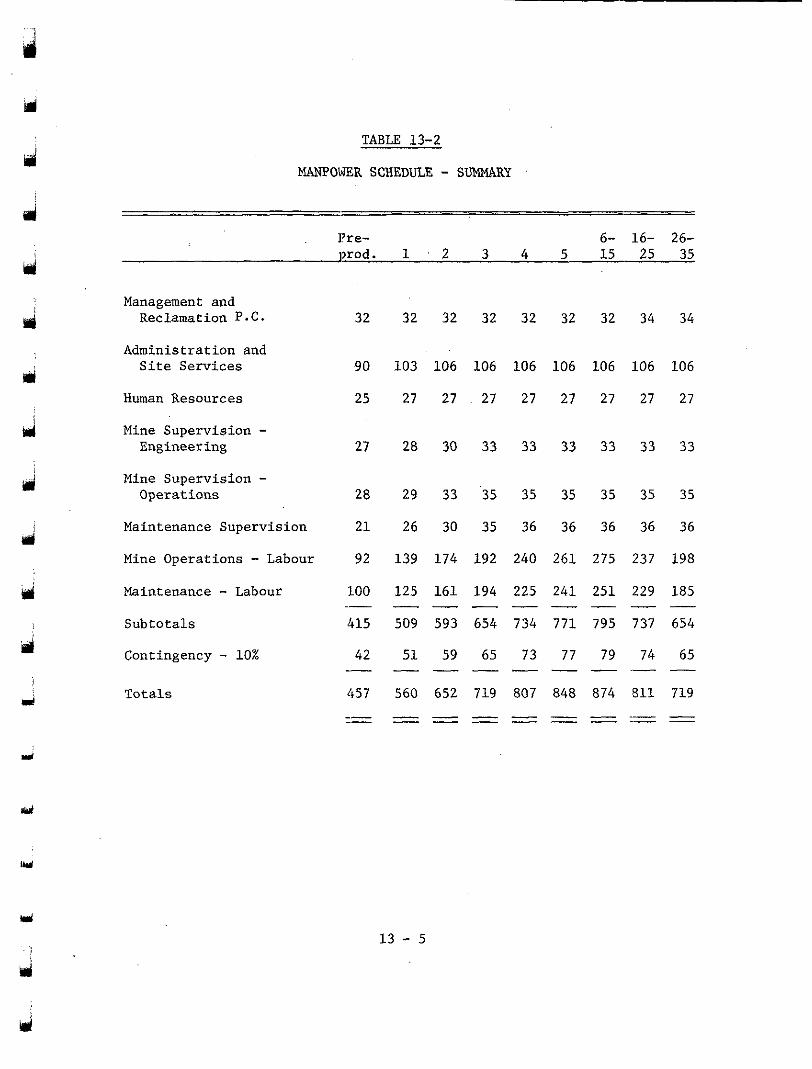
ij
d TABLE 13-2
MANPOWER SCHEDULE - SUMMARY
d ]?re- 6- 16- 26- prod. 1 , 2 3 4 5 15 25 35
hi
4 Management and
Reclamation P.C. 32 32 32 32 32 32 32 34 34
rpi
ii
tal i
d
d
Administration and Site Services
Human Resources
Mine Supervision - Engineering
Mine Supervision - Operations
Maintenance Supervision
Mine Operations - Labour Maintenance - Labour Subtotals
Contingency - 10%
Totals
90
25
27
28
21
92
100
415
42
"
"
457 " "
103
27
28
29
26
139
125
509
51
-
560 - -
106 106
27 . 27
30 33
33 35
30 35
174 192
161 194
593 654
59 65
"
"
652 719 " "
106
27
33
35
36
240
225
734
73
-
106 106
27 27
33 33
35 35
36 36
261 275
2 4 1 251
771 795
77 79
"
"
848 874 " "
106 106
27 27
33 33
35 35
36 36
237 198
229 185
737 654
74 65
"
"
811 719 " I " -
W
1 3 - 5
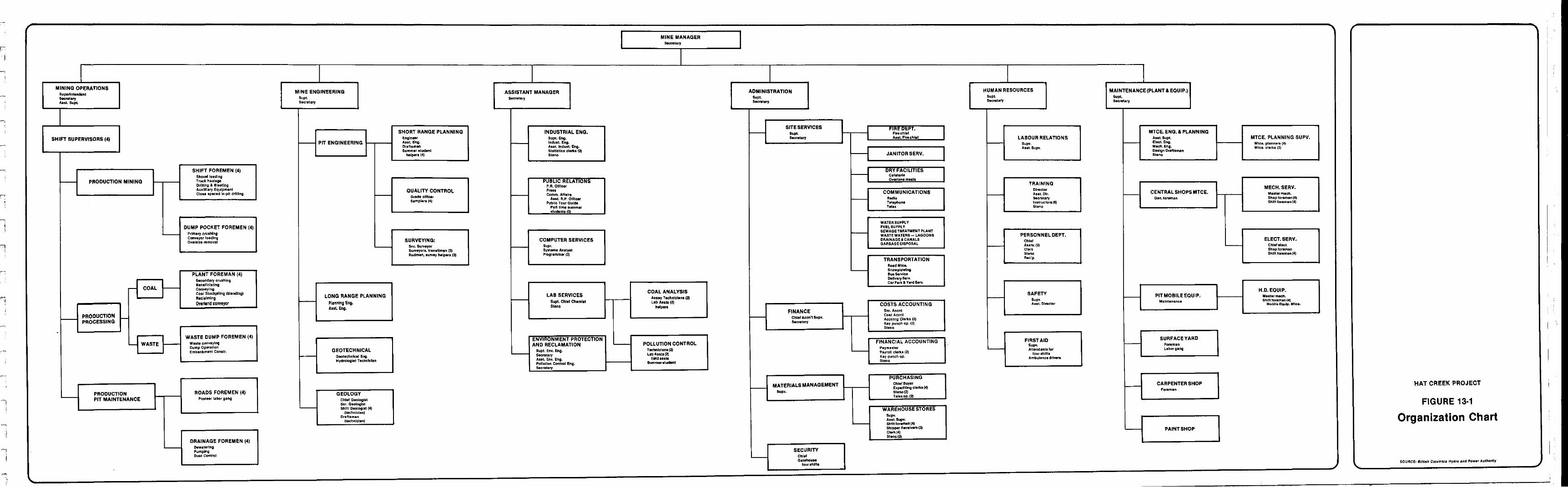
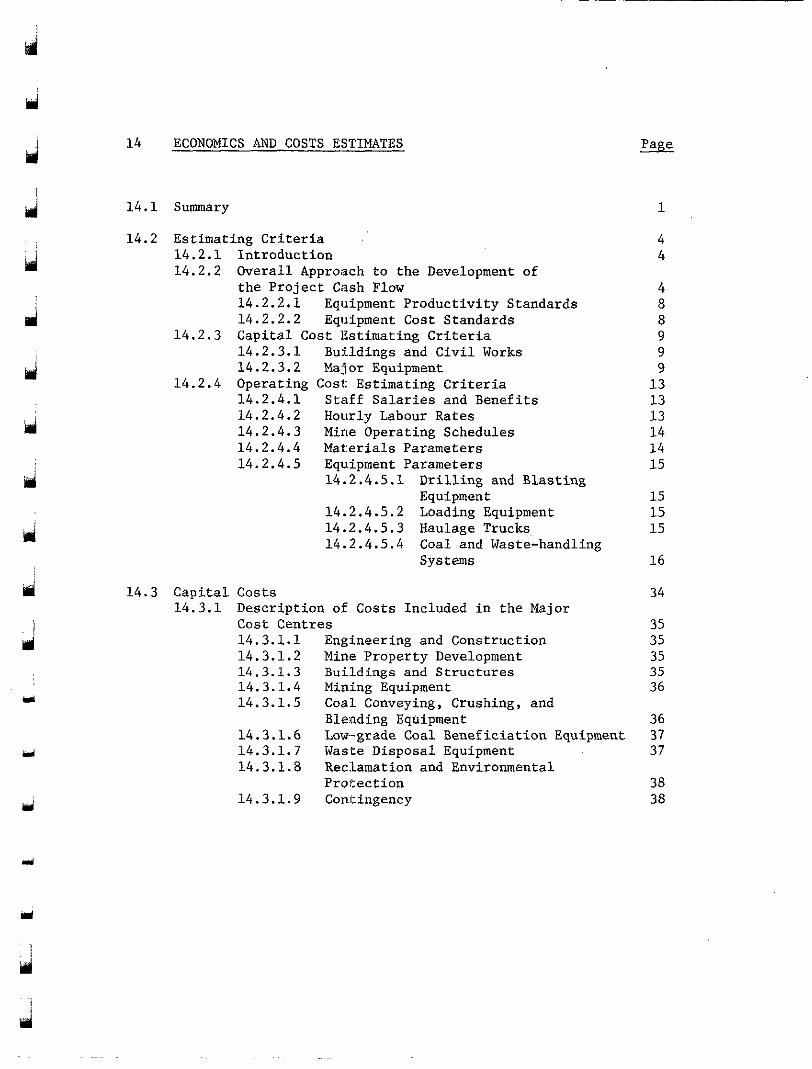
d
llrl I
Y
d
td
14 ECONOMICS AND COSTS ESTIMATES
14.1 Summary
14.2 Estimating Criteria 14.2.1 Introduction 14.2.2 Overall Approach to the Development of
the Project Cash Flow 14.2.2.1 Equipment Productivity Standards 14.2.2.2 Equipment Cost Standards
14.2.3.1 Bufldings and Civil Works 14,2. 3.2 Major Equipment
14.2.4 Operating Cost: Estimating Criteria 14.2.4.1 Staff Salaries and Benefits 14.2.4.2 Hourly Labour Rates 14.2.4.3 Mine Operating Schedules 14.2.4.4 Mat:erials Parameters 14.2.4.5 Equipment Parameters
14.2.3 Capital Cost Ihtimating Criteria
14.2.4.5.1 Drilling and Blasting Equipment
14.2.4.5.2 Loading Equipment 14.2.4.5.3 Haulage Trucks 14.2.4.5.4 Coal and Waste-handling
Systems
14.3 Capital Costs 14.3.1 Description of Costs Included in the Major
Cost Centres 14.3.1.1 Engineering and Construction 14.3.1.2 Mine Property Development 14.3.1.3 Buildings and Structures 14.3.1.4 Mining Equipment 14.3.1.5 Coal Conveying, Crushing, and
14.3.1.6 Low-grade Coal Beneficiation Equipment Blending Equipment
14.3.1.7 Was.te Disposal Equipment 14.3.1.8 Rec:Lamation and Environmental
14.3.1.9 Contingency Protection
1
4 4
4 8 8 9
9 9
13
13 13
14 14 15
15
15 15
16
34
35 35
35 35
36
36
37 37
38 38
3
3
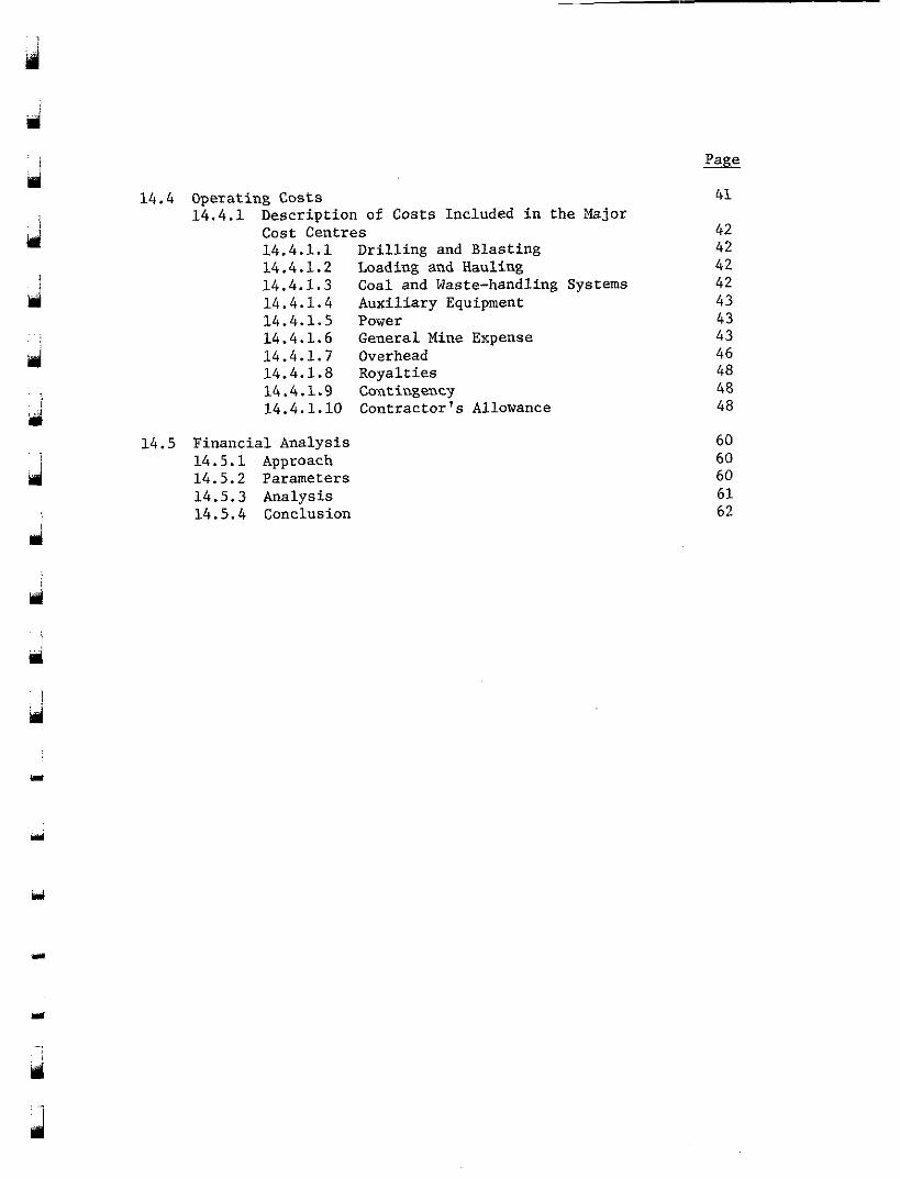
d ,
ui i
. .
d
14.4 Operating Costs 14.4.1 Description of Costs Included in the b j o r
Cost Centres 14.4.1.1 Drilling and Blasting
14.4.1.3 Coal and Waste-handling Systems 14.4.1.2 Loading and Hauling
14.4.1.4 Auxiliary Equipment 14.4.1.5 Power
14.4.1.7 Overhead 14.4.1.6 General Mine Expense
14.4.1.8 Ro:yalties 14.4.1.9 Ccsntingency 14.4.1.10 Contractor's Allowance
14.5 Financial Analysis 14.5.1 Approach 14.5.2 Parameters 14.5.3 Analysis 14.5.4 Conclusion
41
42
42 42
42 43
43 43
46 48
48
60 60 60 61 62
48
Y
3
Y
J
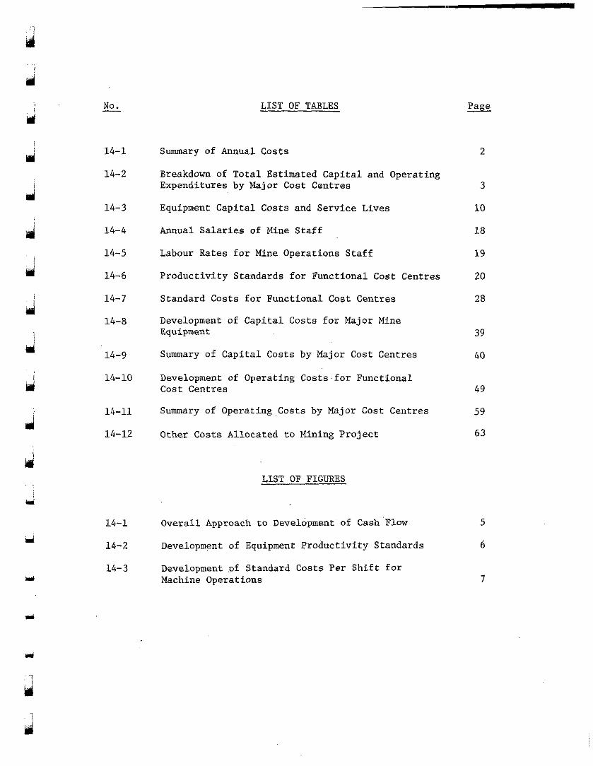
Ki
No. -
14-1
14-2
14-3
14-4
14-5
14-6
14-7
14-8
14-9
LIST OF TABLES
Summary of Annual Costs
Expenditures by Major Cost Centres Breakdown of Total Estimated Capital and Operating
Equipment Capital Costs and Service Lives
Annual Salaries of Mine Staff
Labour Rates for Mine Operations Staff
Productivity Standards for Functional Cost Centres
Standard Costs for Functional Cost Centres
Development of Capital Costs for Major Mine Equipment
Summary of Capital Costs by Major Cost Centres
2
3
10
18
19
20
28
39
40
14-10 Development of Operating Costs for Functional Cost Centres 49
14-11 Summary of 0perat.ing Costs by Major Cost Centres 59
14-12 Other Costs Alloc.ated t o Mining Project 63
LIST OF FIGURES
14-1 Overall Approach to Development of Cash Flow 5
14-2 Development of Equipment Productivity Standards 6
14- 3 Machine Operations Development .of Standard Costs Per Shift for
7
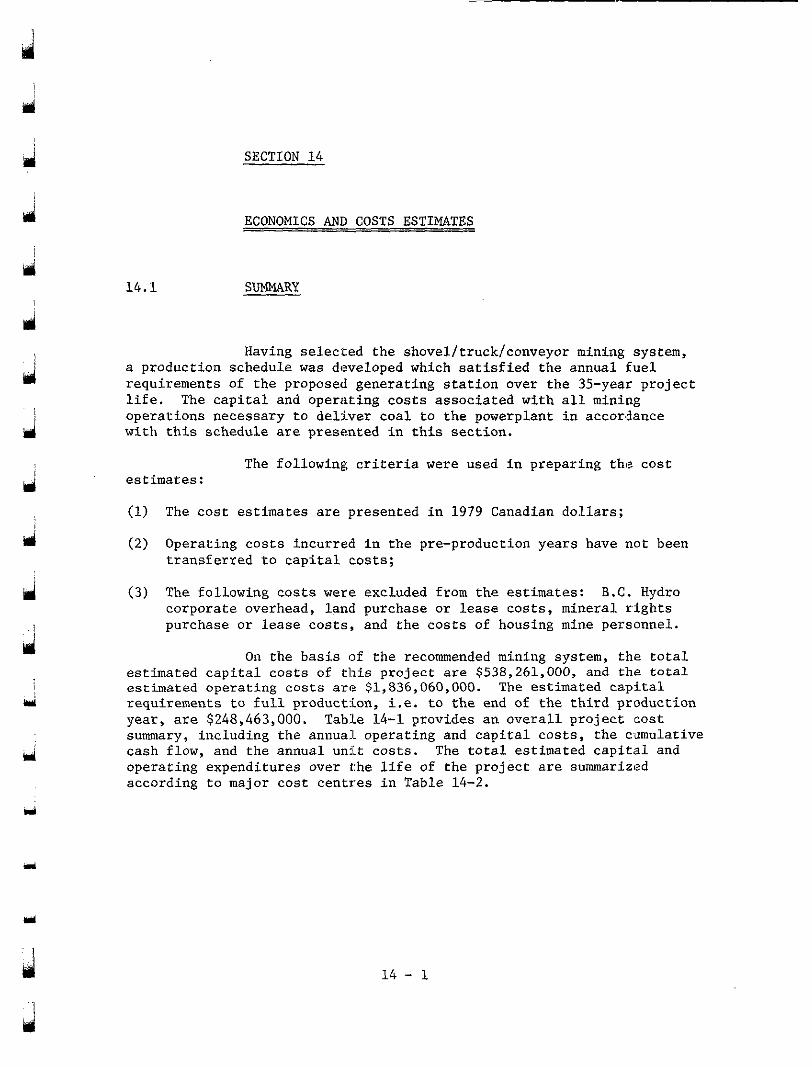
a i
a
m
SECTION 14
ECONOMICS AND COSTS ESTIMATES
14.1 SUMMARY
a production schedule was developed which satisfied the annual fuel requirements of the proposed generating station over the 35-year project life. The capital and operating costs associated with all mining
with this schedule are presented in this section. operations necessary to deliver coal to the powerplant in accor,3ance
Having selected the shovel/truck/conveyor mining system,
estimates:
(1) The cost estimates are presented in 1979 Canadian dollars;
(2) Operating costs incurred in the pre-production years have not been
The following criteria were used in preparing the cost
transferred to capital costs;
( 3 ) The following costs were excluded from the estimates: B.C. Hydro corporate overhead, land purchase or lease costs, mineral rights purchase or lease costs, and the costs of housing mine personnel.
estimated capital costs of this project are $538,261,000, and the total On the basis of the recommended mining system, the total
estimated operating costs are $1,836,060,000. The estimated capital requirements to full production, i.e. to the end of the third production year, are $248,463,000. Table 14-1 provides an overall project cost summary, including the annual operating and capital costs, the ciumulative cash flow, and the annual unit costs. The total estimated capital and operating expenditures over the life of the project are summarized according to major cost centres in Table 14-2.
3
3
14 - 1
d 'i
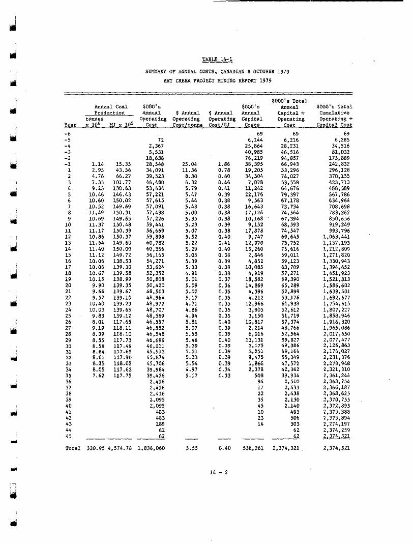
TABLE 14-1
SUMMARY OF ANNUAL COSTS, CANADIAN $ OCTOBER 1979 HAT CREEK PROJECT HINING REPORT 1979
Annual Coal $000'~ $000 1 8 $000'~ Total
Annual Production
SOOO's Total Annual $ Annual $ Annual Annual Operacing Operacing Operating Capital Operating Operating +
Capital + Cumulacive
Year x lo6 MI x l o 9 Cost Cost/conne Cost1G.J Costs cost Capital Cost t o m e s
-6 -5 -4 -3 -2 -1 1 2 3 4
6 5
8 7
10 9
11 12 13 14 15
17 16
18 19 20 21 22 23 24 25
27 26
28 29 30 31 32 33 34 35 36 37 38 39 40 41
43 42
44 45
1.14 2.95 4.76
9.23 7.35
10.46 10.60 10.52 11.49 10.69 11.37 11.17 10.86 11.64 11.40 11.12 10.06 10.06 10.67 10.15 9.90 9.66
10.40 9.57
10.03 9.83 8.01 9.19 8.39 8.55 8.58 8.64 8.61 8.25 8.05 7.62
15.35 43.56
101.77 66.27
130.63 146.43 150.02 149.69 150.31 149.65 150.48 150.39 150.37 149.60 150.00 149.72 138.53 139.30 139.58 138.99 139.35 139.67 139.10 139.23 139.65 139.12 117.65 118.11 118.10 117.73 117.49 117.65 117.90
117.62 118.02
117.75
2,367 72
18,638 5,531
28,548 34,091 39,523 46,480 53,434 57,221 57,615 57,091 57,438 57,226 59,441 56.669 59,898
60,356 60,782
56,165 54,271 53,624 52,352 50,808 50,420 48,503 48,964 48,972 48,707 48,569 46,557 46,552 46,548 46,696 46,211 45,913 45,874 45,706 39,984 39,426 2,416 2,416 2,416 2,095 2,095 483
289 62
483
62 - Total 330.95 4,574.78 1,836,060
I
25.04 11.56 8.30 6.32 5.79 5.41 5.44 5.43 5.00 5.35 5.23 5.07 5.52 5.22 5.29
5.39 5.05
5.33 4.91 5.01 5.09 5.02 5.12
4.86 4.11
4.94 5.81 5.07 5.55 5.46 5.39 5.31 5.33 5.54 4.97 5.17
- 5.55
1.86 0.78 0.60
0.41 0.46
0.39 0.38 0.38 0.38 0.38 0.39 0.38 0.40 0.41 0.40 0.38 0.39 0.38 0.38 0.37 0.36 0.35 0.35
0.35 0.35
0.35 0.40 0.39 0.39 0.40 0.39
0.39 0.39
0.39 0.34 0.33
- 0.40
14 - 2
69
25,864 6,144
40.985 76,219 38,395 19.205 34,504
11,242 7,078
22,176 9.563 16,643
10,168 17,126
9.152 17,878 9,747 12,970 15,260
4,852 2,846
10,085 4,919 18,582 14, 869 4,396 4,212 12,966 3,905
10,817 3,150
2,214 6,016 13,131 3.175 3,251 9,475 1,866 2,378 508
17 94
22 35 45 10 23 14
538,261
6,216 69
28,231 46.516 94,857 66,943 53,296 74,027 53,558 64,676 79,397 67,178 73,734
67,394 74,564
68,593 74,547 69,645 73,752 75,616 59,011 59,123 63,709 57,271 69,390 65,289 52,899 53.176 61,938 52,612 51.719 57,374 48,766 52,564
49,386 59,827
49,164
42,362 47,572
39,934 2,510 2,433 2,438 2,130 2,140 493 506 303 62 62
2,374,321
55,349
6,285 69
34,516 81.032
175,889 242,832 296,128 370,155 423,713 488,389 567,786 634,964 708,698
850,656 783,262
919,249
1,063,441 993,796
1.137.193 1; 212; 809 1,271,820 1,330,943 1,394,652 1,451,923 1,521,313 1,586,602 1,639,501 1,692,677 1,754,615 1,807,227 1,858,946 1,916,320 1,965,086 2,017,650
2,126,863 2,077,477
2,176,027 2,231,376 2,278,948 2,321.310 2,361,24& .2,363,754 :!,366,187 %,368,625 ;!,370,755 i! ,372,895 2,373,388 %,373,894 1,274,197 2,374,259 2,374.321
2,374,321
~.
J
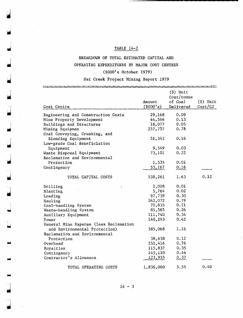
d
d Engineering and Construction Costs Mine Property Development
Mining Equipmen Buildings and Structures
Coal Conveying, Crushing, and
Low-grade Coal Beneficiation
Waste Disposal Equipment Reclamation and Environmental
Contingency
Blending Equipment
Equipment
Protection
TOTAL CAPITAL COSTS
Drilling Blasting Loading Hauling Coal-handling System Waste-handling System Auxiliary Equipment Power General Mine Expense (less Reclamation
Reclamation and Environmental
Overhead Royalties Contingency Contractor’s Allowance
and Environmental Protection)
Protection
TABLE 14-2
BREAKDOWN OF TOTAL ESTIMATED CAPITAL AND OPERATING EXPENDITURES BY MAJOR COST CENTRES
( $ 0 0 0 ’ ~ October 1979)
Hat Creek Project Mining Report 1979
($) Unit Cost/tonne
Amount of Coal ($) Unit Cost Centre ($000 ’~ ) Delivered Cost/GJ
TOTAL OPERATING COSTS
29,168 44,566
257,757 18,077
51,341
73 ,101 9,549
53,167 1,535
538,261
2,008 5,764
262,072 97,739
70,835
111,740 85,585
140,293
385,068
251,416 38,638
115,837 145,110 123,955
1,836,060
0.09 0 .13 0.05 0 .78
0.16
0.03 0 .22
0.01 0 .16 I_ I_
1.63 0.12
0.01 0.02 0.30 0.79 0.21 0 .26 0.34 0.42
1 .16
0.12 0.76 0.35
0.37 0.44
- 5.55 0.40
1 4 - 3
j
r yi 14.2
14.2.1
ESTIMATINE CRITERIA
Introduction
This section of the report discusses the approach used in developing the cash flow of capital and operating costs for the recom- mended mining scheme.
cerning the cost and service life of the major equipment, are provided in Section 14.2.3.
The capital cost estimating criteria, primarily con-
costs are presented in Sec:tion 14.2.4 and consist mainly of labour rates and major equipment produc.tivity and cost standards.
The estimat:ing criteria used in developing the operating
14.2.2 Overall Approach to the Development of the Project Cash Flow
costs is shown in Figures . l4-1, 14-2, and 14-3. The system .used to develop annual capital and operating
Having determined a practical and economic production
next phase of the study was to carry out an analysis to determine the schedule for the recommended shovel/truck/conveyor mining system, the
size and type of shovels and trucks to be employed in the mining op- eration. This analysis is discussed in Section 9. Basically, owning and operating costs were developed for various combinations of shovel/ truck systems at critical periods during the life of the project. An analysis of this information then resulted in the selection of the shovels and trucks for the mining system. Capital and operating costs for the major mining equipment were then produced for the project life.
A l l additional costs to support the mining system were then developed. These include the costs for all auxiliary equipment,
mental protection, overhead and general mine expenses. support facilities, material-handling systems, reclamation and environ-
14 - 4
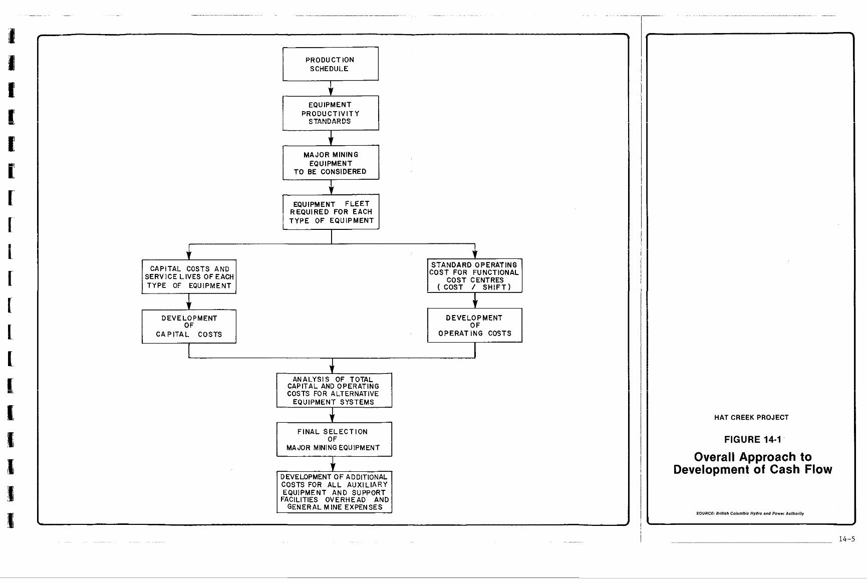
~ ~ .... . .... ... . . .. . . . . .. .. . . . . ~ . .. ..... . . . . . . . .. . . . . ... . . . .~.. . .~. ...... .. ...~ ........ ~ .... ~ . . . . . ~ ~ . . .
I
PRODUCTION SCHEDULE I EQUIPMENT
PRODUCTIVITY I S?A%EARES I
MAJOR MINING EQUIPMENT
TO BE CONSIDERED
r c REQUIRED FOR EACH EQUIPMENT F L E E T
TYPE OF EQUIPMENT . . SERVICE LIVES OFEACH
CAPITAL COSTS AND
TYPE OF EQUIPMENT
I DEVELOPMENT OF I
I C A P I T A L COSTS I
COST FOR FUNCTIONAL STANDARD OPERATING
DEVELOPMENT OF
OPERATING COSTS
J 1
CAPITAL AND OPERATING ANALYSIS OF TOTAL
COSTS FOR ALTERNATIVE EQUIPMENT SYSTEMS
I
F I N A L S E L E C T I O N OF
MAJOR MINING EQUIPMENT
J- DEVELOPMENT OF ADDITIONAL COSTS FOR ALL AUXIL IARY
FACILITIES OVERHEAD AND EQUIPMENT AND SUPPORT
GENERAL MINE EXPENSES
HATCREEKPROJECT
FIGURE 14-1 '
Overall Approach to Development of Cash Flow
SOURCE: British Coiumbh Hydro and Power Authority
14-5
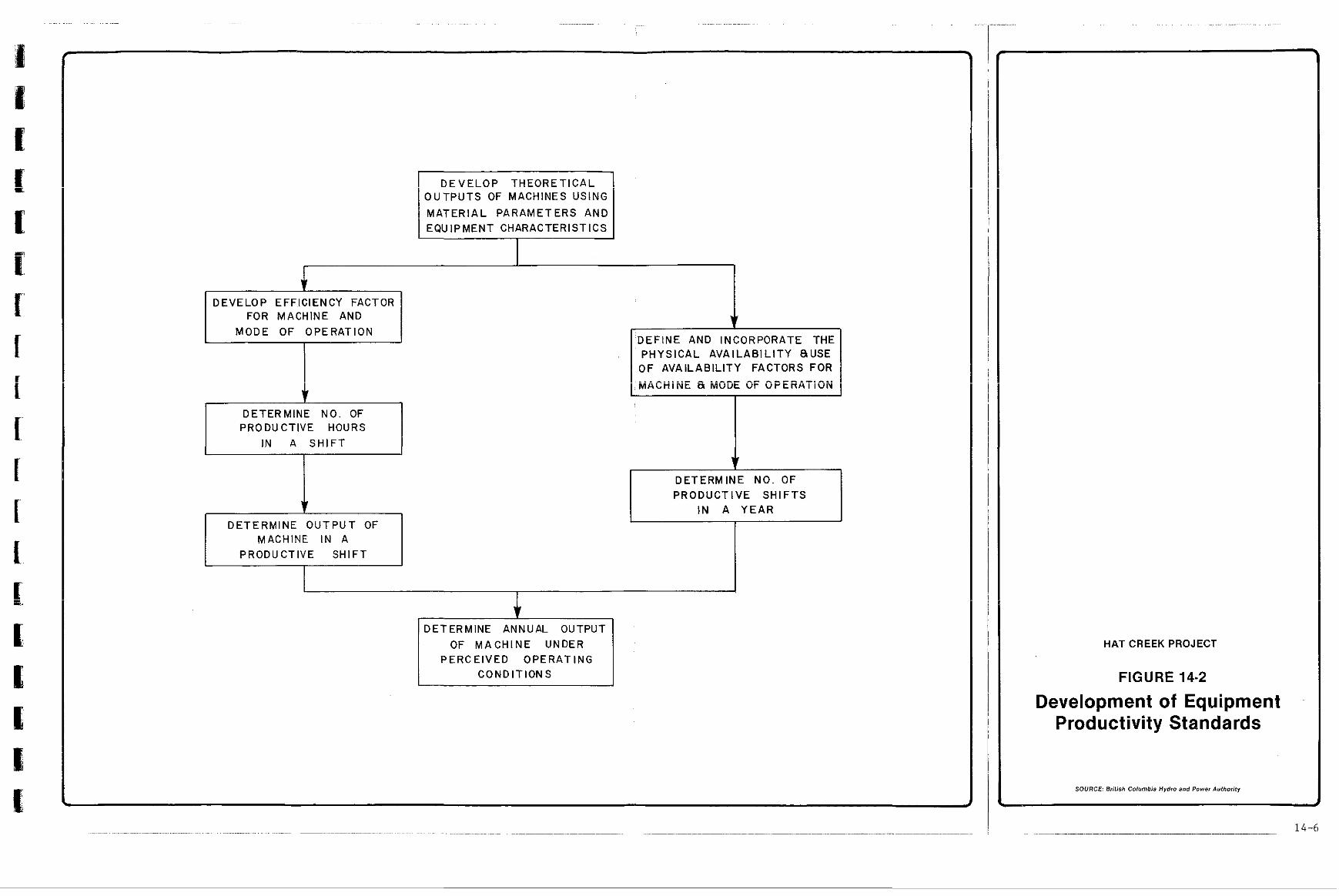
I D E V E L O P T H E O R E T I C A L I O U T P U T S OF MACHINES USING MATERIAL PARAMETERS AND EQUIPMENT CHARACTERISTICS
DEVELOP EFFICIENCY FACTOR FOR MACHINE AND
MODE OF OPERATION
I
DETERMINE NO. OF PRODUCTIVE HOURS
I D E T E R M I N E O U T P U T OF
MACHINE IN A PRODUCTIVE SHIFT
I AND INCORPORATE THE
PHYSICAL AVAILABIL ITY RUSE OF AVAILABILITY FACTORS FOR
I ... . . ^ " " " " " . ^ . . I ,MALHINL a M u m ur u r t r w 1 1 ~ ~
DETERMINE NO. OF PRODUCTIVE SHIFTS
IN A Y E A R
I I
I
il
DETERMINE ANNUAL OUTPUT OF MACHINE UNDER
PERCEIVED OPERATING CONDITIONS
HATCREEKPROJECT
FIGURE 14-2
Development of Equipment Productivity Standards
SOURCE British Columbia Hydro and Power Authority
.... ~~ ~ .............. . . .... . . . ~ .... ~~~ ~ ~~ ~ . .
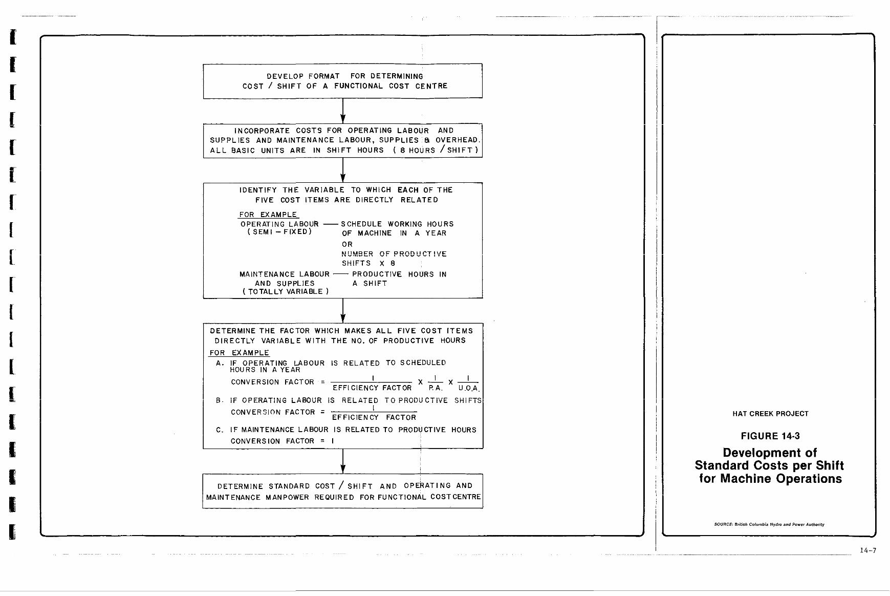
. . ... . . . .~ . .... .. .. . .. . .. . . .... . ... .. . ... . .. . ~~
DEVELOP FORMAT FOR DETERMINING COST / S H I F T O F A FUNCTIONAL COST CENTRE
INCORPORATE COSTS FOR OPERATING LABOUR AND SUPPLIES AND MAINTENANCE LABOUR, SUPPLIES ' & OVERHEAD. A L L B A S I C U N I T S A R E I N S H I F T H O U R S ( 8 HOURS / S H I F T )
IDENT1FY THE VARIABLE TO WHICH EACH OF THE F I V E COST ITEMS ARE DIRECTLY RELATED
FOR EXAMPLE OPERATING LABOUR -
( S E M I - F I X E D ) SCHEDULE WORKING HOURS OF MACHINE IN A YEAR
OR ?!".!BED O F P!?OD"CT!?E S H I F T S X 8
MAINTENANCE LABOUR - PRODUCTIVE HOURS IN
( TOTALLY VARIABLE AND SUPPLIES A S H I F T
DETERMINE THE FACTOR WHICH MAKES A L L F I V E C O S T I T E M S D I R E C T L Y V A R I A B L E W I T H T H E NO. OF PRODUCTIVE HOURS
FOR EXAMPLE A. IF OPERATING LABOUR IS RELATED TO SCHEDULED
HOURS IN A YEAR
CONVERSION FACTOR = I I I EFFl CIENCY FACTOR
x - x - I? A. U.0.A
E . O P E R A i i N G LABeGR is 2 E i A T E D TO p ~ O i j ~ C T i ~ v ' E SHiFTi
CONVERSION FACTOR = I EFFICIENCY FACTOR
C. IF MAINTENANCE LABOUR IS RELATED TO PRODVCTIVE HOURS
CONVERSION FACTOR = I !
1 i I i -
DETERMINE STANDARD COST / SHIFT A N D OPERATING AND MAINTENANCE MANPOWER REQUIRED FOR FUNCTIONAL COSTCENTRE
HAT CREEK PROJECT
FIGURE 14-3
Development of Standard Costs per Shift for Machine Operations
SOURCE British Columbia Hydro and Power Authority
14-7
d
Y
developed with the a id of equipment p roduc t iv i ty and cos t s tandards . Equipment requirements and costs for the project were
14.2.2.1 Equipment Product ivi ty Standards
using the mater ia l parameters and machine character is t ics . The number Theore t ica l hour ly ou tputs of machines were produced
of product ive hours in a s h i f t were then determined for the mode of operation envisaged. From these f ac to r s t he ac tua l ou tpu t of a machine i n a s h i f t was ca lcu la ted . The experience of opera t ing mines was used t o d e v e l o p t h e p h y s i c a l a v a i l a b i l i t y of machines working under a p a r t i c u l a r
enabled the number of p r o d u c t i v e s h i f t s i n a yea r t o be ca l cu la t ed . regime, as well a s t h e u s e o f such avai labi l i ty . These parameters
Knowing the machines ' output i n a s h i f t and t h e number of product ive
expected operat ing condi t ions was determined. s h i f t s i n a year , the annual p roduct iv i ty of t h e machine under c e r t a i n
14.2.2.2 Equipment Cost: Standards
bd
developed from the following f ive cost items: opera t ing labour , opera t ing supplies, maintenance labour, maintenance parts and supplies, and main- tenance overhead. These cost standards were developed on a s h i f t b a s i s similar to t hose of the p roduct iv i ty s tandards .
The c o s t s t a n d a r d s f o r d i f f e r e n t p i e c e s of equipment were
Depending on the mode of operat ion, equipment , f leet
f ixed, variable, or semi-fixed. For each cost item t h e p r i c e p e r b a s i c s ize , labour agreements , etc.,, t he cos t item can be es tabl ished as
u n i t was ident i f ied (e .g . l abour rate f o r a shovel opera tor , power cos t per hour of shovel operat ion) , and t h e v a r i a b l e t o which t h i s b a s i c u n i t was related (e.g. scheduled working hours, productive hours). From these da ta the s tandard cos t per sh i f t fo r each major p iece of e'quipment was e s t ab l i shed . The cost data used in these calculat ions were 'based on
development of a cos t s tandard for each p iece of equipment i n a func t iona l the experience of operating mines in the Province. From the sys temat ic
cos t cen t r e , i t was then poss ib l e t o bu i ld up the ope ra t ing and maintenance manpower requirements.
P;
Y
14 - 8
J
m
Y
14.2.3
14.2.3.1
Cap i t a l Cost Eistimating Criteria
Buildings and Civi l Works
account prevail ing labour agreements and p r o d u c t i v i t y i n t h e B.C. cons t ruc t ion indus t ry . Uni t cos t s of major b u i l d h g components were reviewed with t rade contractors .
The c o s t s of c:ivil works were developed taking in.to
14.2.3.2 Major Equipment -
The capital costs for the major mobile mining equipment and the coal conveying, crushing, and blending equipment were developed based on manufac tu re r s ' l i s t ed p r i ces and quota t ions in October 1979 d o l l a r s . The c a p i t a l u n i t c o s t f o r e a c h item of equipment includes:
- purchase cost of equipment FOB f ac to ry ;
- a l lowance for op t iona l ex t ras ;
- f r e i g h t and insurance to site;
- Prov inc ia l sales t a x a t 4% of FOB s i te cos t ;
- e r e c t i o n cost!; a t s i te .
Where manufacturers ' quotat ions were in U.S. dol l .srs , an exchange r a t e of $1.15 Canadian t o $1.00 U.S. was used. A summary of the c a p i t a l c o s t s and s e r v i c e l i v e s of the major equipment is presented
mendations and partly on ac tua l f i gu res ob ta ined from a survey of i n T a b l e 14-3. These f igures a re based par t ly on supp l i e r s ' recom-
similar operat ions.
Y
Y
1 4 - 9
Y
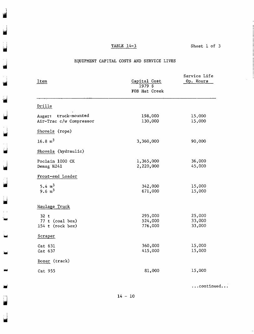
Y
Y
im
Y
Y
Item
TABLE 14-3
EQUIPMENT CAPITAL COSTS AND SERVICE LIVES
Sheet 1 of 3
Capital Cost Service Life Op.Hours
1979 $ FOB Hat Creek
Drills
Augert truck-mounted Air-Trac c/w Compressor
Shovels (rope)
16.8 m3
Shovels (hydraulic)
Poclain 1000 CK Demag HZ41
Front-end Loader
5.4 m3 9.6 m3
Haulage Truck
32 t
154 t (rock box) 77 t (coal box)
Scraper
Cat 631 Cat 637
Dozer (track)
Cat 955
198,000 130,000
3,360,000
1,365,000 2,220,000
342,000 671,000
295,000 524,000 776,000
360,000 415,000
81,000
15,000 15,000
90,000
36,000 45,000
15,000 15,000
25,000 33,000 33,000
15,000 15.000
15,000
... continued...
l
14 - 10
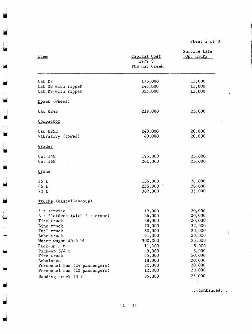
Sheet 2 of 3
Capital Cost &Hours 1979 $
FOB Hat Creek
Service Life
. .
Item -
. ,
d
ispi
-i
ri
Cat D7 Cat D8 with ripper Cat D9 with ripper
Dozer (wheel)
Cat 824B
Compactor
Cat 825B Vibratory (towed)
Grader
Cat 14G Cat 16G
Crane
15 t 45 t 70 t
Trucks (miscellaneous)
5 t service
Tire truck 3 t flatdeck (with 2 t crane)
Line truck Fuel truck
Water wagon 45.5 kL Lube truck
Pick-up 314 t
Ambulance Fire truck
Personnel bus (12 passengers) Personnel bus (24 passengers)
Sanding truck 10 t
Pick-up 1 t
175,000 246,000 355,000
15,000 15,000 15,000
219,000 25,000
240,000 40,000
195,000 261,000
135,000 255,000 382,000
19,000 26,000 38,000 70,000 60,000 91,000
300,000 11,000 9,000
65,000 18,000 20,000 12,000 35,000
20,000 20,000
25,000 25,000
20,000 20,000 35,000
20,000 20,000 20,000 32,000 20,000 20,000 25I,OOO
8,000 8,000
50,000 20,000 20,000 20,000 25,000
.continued. . .
ui 14 - 11
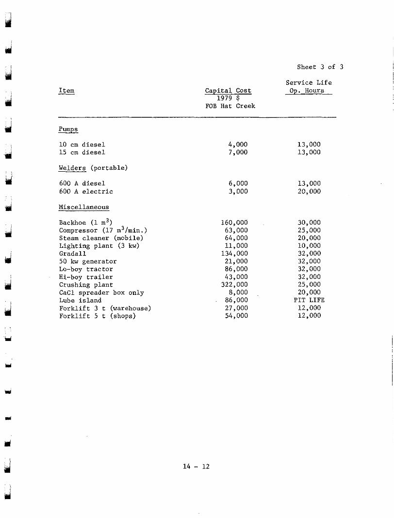
Sheet 3 of 3
Service Life Op.3ours
irl . .
Ij
I tem - Capital Cost 1979 $
FOB Hat Creek
pumps
10 cm diesel 15 cm diesel
Welders (portable)
600 A diesel 600 A electric
Miscellaneous
Backhoe (1 m3) Compressor (17 m3/rnin.) Steam cleaner (mobile) Lighting plant ( 3 kw) Gradall 50 kw generator Lo-boy tractor Hi-boy trailer Crushing plant CaCl spreader box only Lube island Forklift 3 t (warehouse) Forklift 5 t (shops)
4,000 7,000
6 ,000 3,000
160,000 63,000 64,000 11,000
134,000 21,000 86,000 43,000
322,000 8,000
86,000 27,000 54,000
13,000 13 ,000
13,000 20 ,000
30,000 25,000 20,000 10,000
32,000 32,000
32,000 32 ~ 000 25,000 20,000
PIT LIFE 12,000 12,000
14 - 12
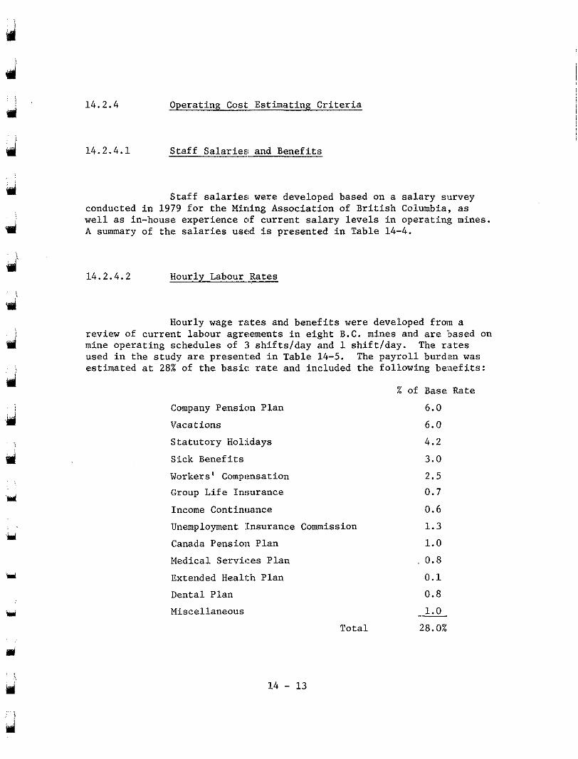
9
'ri
Y
i,
14 .2 .4
14.2.4.1
Operat ing Cost Est imat ing Cri ter ia
Staff Salar ies : and Benefi ts
S t a f f s a l a r i e s ; were developed based on a sa la ry survey conducted i n 1979 f o r t h e Mining Associat ion of B r i t i s h Columbia, as well as in-house experience of cur ren t s a l a ry levels in operat ing mines. A summary of t h e salaries used is presented in Table 14-4.
14.2.4.2 Hourly Labour Rates
Hourly wage rates and b e n e f i t s were developed from a
mine operat ing schedules of 3 s h i f t s / d a y and 1 sh i f t / day . The r.stes review of current labour agreements i n e i g h t B.C. mines and are 'based on
used i n t h e s t u d y are presented in Table 14-5. The payrol l burden was est imated a t 28% of t h e basic: rate and included the fol lowing benefi ts :
Company Pension Plan
Vacations
Statutory Holidays
S ick Benef i t s
Workers' Compensation
Group L i f e In., w r a n c e
Income Continuance
Unemployment :Insurance Commission
Canada Pension Plan
Medical Services Plan
Extended Health Plan
Dental Plan
Miscellaneous
Tota l
% of Base Rate
6.0
6.0
4.2
3.0
2.5
0.7
0.6
1 .3
1.0
0.8
0.1
0.8
1.0
28.0%
!
Y 14 - 13
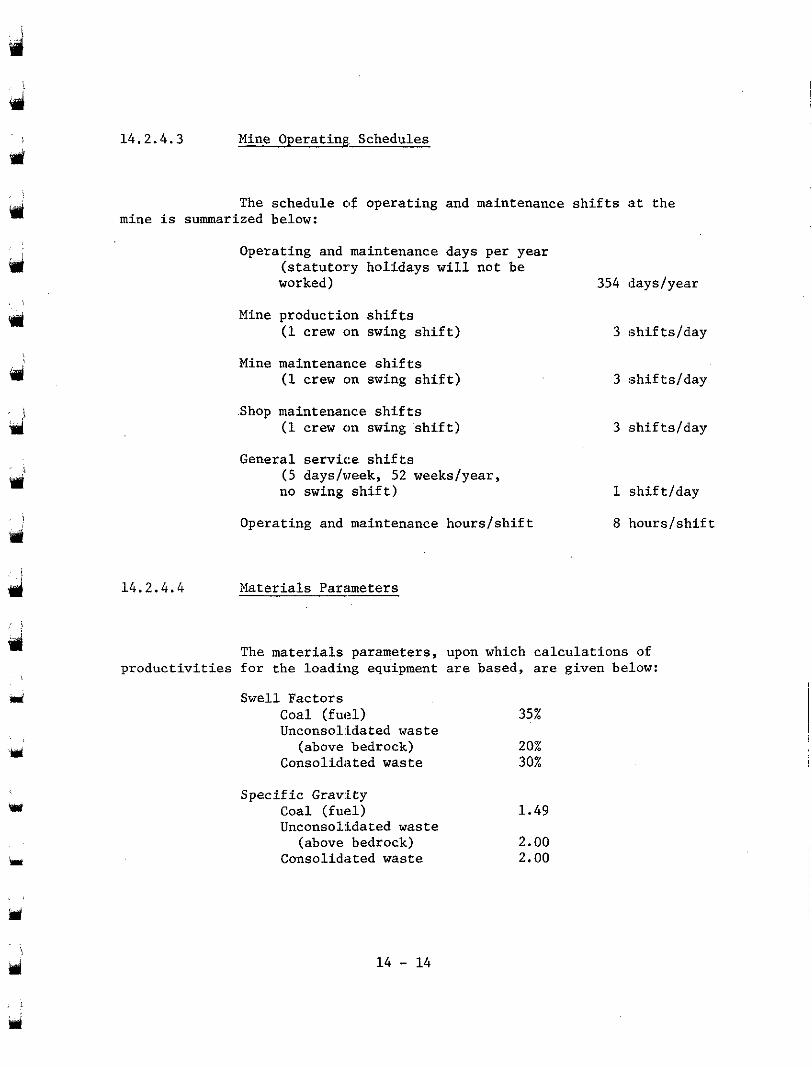
14.2.4.3 Mine Operating Schedules
d
i d
wi i
d I
Lr
The schedule of operating and maintenance shifts at the mine is summarized below:
14.2.4.4
Operating and maintenance days per year
worked) (statutory holidays will not be
Mine production shifts (1 crew on swing shift)
Mine maintenance shifts (1 crew on swing shift)
Shop maintenance shifts (1 crew on swing shift)
General service shifts
no swing shift) (5 dayslvreek, 52 weekslyear,
Operating and maintenance hourslshift
Materials Parameters
354 dayslyear
3 :shif tslday
3 shiftslday
3 shiftslday
1 shiftfday
8 hourslshif t
productivities for the loading equipment are based, are given below: The materials parameters, upon which calculations of
Swell Factors Coal (fuel) 35% Unconsolidated waste
(above bedrock) 20% Consolidated waste 30%
Specific Grav:ity Coal (fuel) 1.49 Unconso1:idated waste
(above bedrock) 2.00 Consolidated waste 2.00
14 - 14
: i
4d \
usl
eri
14.2.4.5 Equipment Parameters
14.2.4.5.1 Drilling and Blasting Equipment
Drilling and blasting operations would be a minor part of the mining system employed at. the Hat Creek Mine. Two drills (one
employed in these operations. Drilling and blasting would be confined crawler and one truck-mounted drill) and one 5-t blasters' truck will be
to approximately 10% of the total waste materials mined.
Tables 14-6 and 14-7 provide the productivity and cost standard for the drills.
14.2.4.5.2 Loading Equipment -
: i
I
d
Hydraulic shovels will be used for loading coal and waste materials, while front-end loaders will be employed as supplementary
while the waste shovels will have 14.5 m3 buckets. The smaller hydraulic loading equipment. Coal shovels will be equipped with 10.7 m3 buckets,
shovels will be required to load waste partings and waste zones within
provide the productivity and cost standards for the shovels performing the major coal zones of the Hat Creek Deposit. Tables 14-6 and 14-7
specific tasks.
It should be noted that the coal shovels will have a low use of availability. This w:L11 occur because of the widespread work areas required to blend the various coals, and it is more economical and practical to have extra pieces of equipment to cover the pit than to have long and frequent equipment moves.
Y
14.2.4.5.3 Haulage Truck!; - Y
some waste partings, while 1,54-t rear dump trucks will be the primary 77-t rear duFp trucks will be used for hauling coal and
waste haulers. These trucks were selected after an economic analysis. (See Section 9 ) The productivities of these trucks in Year 6 and their
14 - 15
Y
I
il
Y
i w
rl
cost standards are provided i n Tables 14-6 and 14-7. Productivities were determined for the trucks throughout the 35-year project life to reflect the changing haulage cycles.
14.2.4.5.4 Coal and Waste-handling Systems
Equipment empl.oyed in the coal and waste-handling systems include truck dump stations, control stations, distributi.on points, permanent and transfer conveyors, spreaders, reclaimers, stackers, crushing plant, and screens. Conveyors will be 1,400 mm wide and vary in speed from 2.5 m/s to 4.5 m/s.
are computed on an annual basis. The operating labour is fixed for a given material-handling system design operating on a given shift schedule. The maintenance labour, parts, supplies, and overhead, as well as operating supplies, are ali determined as a percentage of the capital cost of the equipment.,
The operating costs for coal and waste-handling systems
is "step-fixed", varying only as the material-handling system design changes - such as increasing conveyor lengths and adding equipment.
Using this method of cost estimation, the operating cost
for the waste-handling system in Year 8 when the Houth Meadows Dump is Table 14-10 shows the annual operating cost development
being used and the second truck dump station is in operation. Annual operating costs were developed for various system designs incorporated throughout the project life, and these are reflected in the schedule of operating costs on Table 14-11.
porate the factors used for swell, specific gravity, fill factor, and the speed for a 90' swing cycle of a shovel. An efficiency factor of
productive hours in a shift. 145 minutes of unproductive time c.omprised: 70% was used in all productivity calculations to reflect the actual
(1) shift changes - 30 minutes; (2) lunch break - 30 minutes; (3) 7 x 50-minute hours, i.e. 10 minutes unproductive time per hour -
The productivity standards shown in Table 14-6 in.cor-
70 minutes;
m
14 - 16
i ei
I
;91
Y !
! ‘d
Y
(4) coffee break - 15 minutes.
The machine phys ica l ava i lab i l i ty is def ined as :
Number of s h i f t s t h e machine is mechanically avai lable ( in working condi t ion) per year
Scheduled working shifts/year
The use o f ava i l ab i l i t y i s def ined as :
x 100%
Number of s h i f t s t h e machine is mechanically Working s h i f t s p e r y e a r
a v a i l a b l e per year
x 100%
The use of a v a i l a b i l i t y of a machine would be dependent on the mine ope ra t ing s chedu le , t he f l ee t s i ze of the equipment, and t h e manpower coverage f o r the equipment. The e f f e c t i v e u t i l i z a t i o n which g ives an overa l l opera t ing e f f . i c iency of a pa r t i cu la r p i ece o r t ype of equipment w i l l be the mu1tip:le of t h e t h r e e f a c t o r s above.
The e f f e c t i v e u t i l i z a t i o n is def ined as :
Working hours Scheduled hours - x 100%
1 4 - 1 7
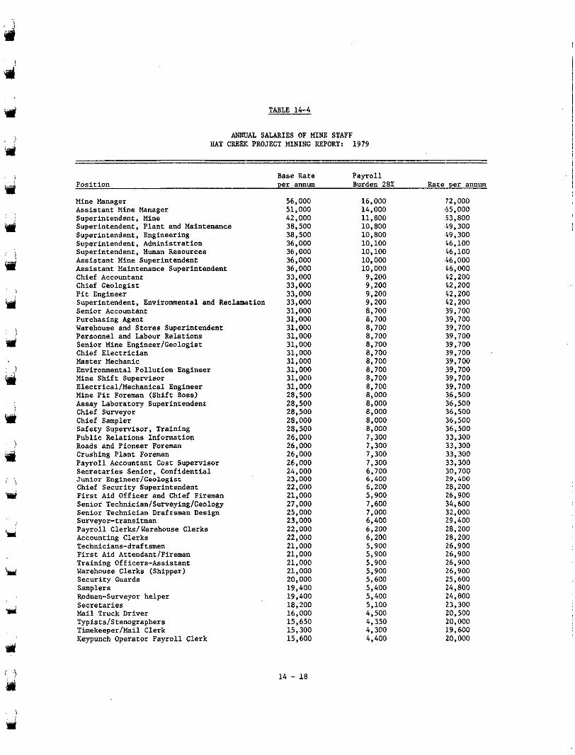
TABLE 14-4
HAT CREEI: PROJECT MINING REPORT: 1979 A N N l J A L SALARIES OF MINE STAFF
I
Y
Y
Position Base Rate per annum
Payroll Burden 28% Rate per annum
Mine Manager Assistant Mine Manager Superintendent, Mine Superintendent, Plant and Maintenance Superintendent, Engineering Superintendent, Administration
Assistant Mine Superintendent Superintendent, Human Resources
Assistant Maintenance Superintendent Chief Accountant Chief Geologist Pit Engineer Superintendent, Environmental and Reclamation
Purchasing Agent Senior Accountant
Warehouse and Stores Superintendent Personnel and labour Relations Senior Mine EngineerIGeologist Chief Electrician Master Mechanic Environmental Pollution Engineer Mine Shift Supervisor ElecCricallMechanical Engineer Mine Pit Foreman (Shift Boss) Assay Laboratory Superintendent
Chief Sampler Chief Surveyor
Public Relations Information Safety Supervisor, Training
Roads and Pioneer Foreman Crushing Plant Foreman Payroll Accountant Cost Supervisor Secretaries Senior, Confidential Junior Englneer/Geologlst Chief Security Superintendent First Aid Officer and Chief Fireman Senior Technician/Surveying/Geology Senior Technician Draftsman Design Surveyor-transitman Payroll Clerkslwarehouse Clerks Accounting Clerks Technicians-draftemen First Aid AttendantlFireman
Warehouse Clerks (Shipper) Training Officers-Assistant
Security Guards Samplers Rodmen-Surveyor helper
Mail Truck Driver Secretaries
Typistslstenographers TimekeeperIMail Clerk Keypunch Operator Payroll Clerk
56,000 51,000 42,000 38,500 38,500
36,000 36,000
36,000 36,000 33,000 33,000 33,000 33,000 31,000 31,000 31,000 31,000 31,000 31,000 31,000 31,000 31,000 31,000 28,500 28,500 28,500 28,000 28,500 26,000 26,000 26,000 26,000 24,000 23,000 22,000 21,000 27,000 25,000 23,000 22,000 22,000 21,000 21,000 21,000 21,000 20,000 19,400 19,400 18,200 16.000 15,650 15,300 15,600
14 - 18
16,000 14,000
72,000 65,000
11.800 .53,800 10,800 .49,300 10.800 .49,300 10,100 ,66,100 10,100 66,100 10,000 10,000
.66,000 46,000
9,200 42.200 9,200 42,200
9,200 9,200 42,200
42,200 8,700 39,700 8.700 39,700 8,700 39,700 8,700 39,700 8,700 39,700 8,700 39,700 8,700 39,700 8,700 39,700 8,700 39,700 8,700 39,700 8,000 36,500 8,000 36,500 8.000 36,500 8,000 36,500 8,000 36,500 7,300 33,300 7,300 33,300 7,300 33,300 7,300 33,300 6,700 30,700 6,400 29,400 6,200 28,200 5,900 26,900 7,600 34,600 7,000 32,000 6,400 29,400 6,200 28,200 6,200 28,200 5,900 26,900 5,900 26,900 5,900 26,900 5,900 26,900 5,600 25,600 5,400 24,800 5,400 5,100
24.800
4,500 23.300 20,500
4,300 4,350 20,000
19,600 4,400 20,000
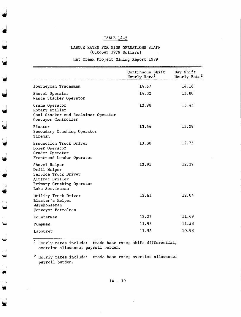
TABLE 14-5
LABOUR RATES FOR MINE OPERATIONS STAFF (October 1979 Dollars)
Hat Creek Project Mining Report 1979
Continuous Shift Day Shift Hourly Ratel Hourly Rate'
Journeyman Tradesman 14.67 14.16
d
Y
Y
i w
* !
Shovel Operator Waste Stacker Operator
14.32 13.80
Crane Operator 13.98 13.45 Rotary Driller Coal Stacker and Reclaimer Operator Conveyor Controller
Blaster Secondary Crushing Operator Tireman Production Truck Driver Dozer Operator Grader Operator Front-end Loader Operator Shovel Helper Drill Helper
Airtrac Driller Service Truck Driver
Primary Crushing Operator Lube Serviceman
Utility Truck Driver
Warehouseman Blaster's Helper
Conveyor Patrolman Counterman Pumpman
13.64
13.30
12.95
13.09
12.75
12.39
12.61 12.04
12.27 11.69
11.93 11.28
Labourer 11.58 10.98
Hourly rates include: trade base rate; shift differential; overtime allowance; payroll burden.
Hourly rates include: trade base rate; overtime allowance; payroll burden.
' i w
14 - 19
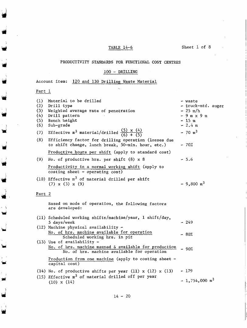
‘rl
W !
Y
Y
w
TABLE 14-6
PRODUCTIVITY STANDP.3DS FOR FUNCTIONAL COST CENTRES
- 1.00 - DRILLING
Account item: 120 and 130 Drillinp Waste Mater ia l
Part 1
M a t e r i a l t o b e d r i l l e d Drill type Weighted average rate of pene t ra t ion Drill p a t t e r n Bench he ight Sub-grade
E f f e c t i v e m3 m a t e r i a l / d r i l l e d
E f f i c i e n c y f a c t o r f o r d r i l l i n g o p e r a t i o n ( l o s s e s due t o s h i f t change, lunch break, 50-min. hour , e tc . )
( 5 ) x ( 4 ) ( 6 ) + (5)
Product ive hours per shi . f t - (apply to s tandard cos t )
(9 ) No. of p roduc t ive h r s . pe r sh i f t (8) x 8
P r o d u c t i v i t y i n a normal. working s h i f t ( a p p l y t o cos t ing shee t - opera t ing cos t )
(10) E f f e c t i v e m3 of material. d r i l l e d p e r s h i f t (7) x (3) x (9)
Sheet 1 of 8
- waste - truck-mtd. auger - 25 mfh
- 15 m - 9 m x 9 m
- 2.4 m
- 70 m3
- 70:%
- 5.6
- 9,800 m3
P a r t 2
Based on mode of operat i .on, the fol lowing factors are developed:
(11) Scheduled working shif ts/machine/year, 1 sh i f t fday ,
(12) Machine p h y s i c a l a v a i l a b i l i t y - 5 daysfweek - 249
No. of h r s . machine avai. lable for operation Scheduled working hrs. i n p i t - 807:
(13) Use of a v a i l a b i l i t v - . ~ ~ I ~~~
No. of hrs. machine mann.ed & avai lab le for p roduct ion No. of hrs . machin.e a v a i l a b l e f o r o p e r a t i o n - 902
Production from one mach.& (apply t o cos t ing shee t - c a p i t a l c o s t )
(14) NO. of p roduc t ive sh i f t s pe r yea r (11) x (12) x (13) - 1751 (15) E f fec t ive m3 of material d r i l l ed o f f pe r yea r
(10) x (14) - 1,754,000 m3
14 - 20
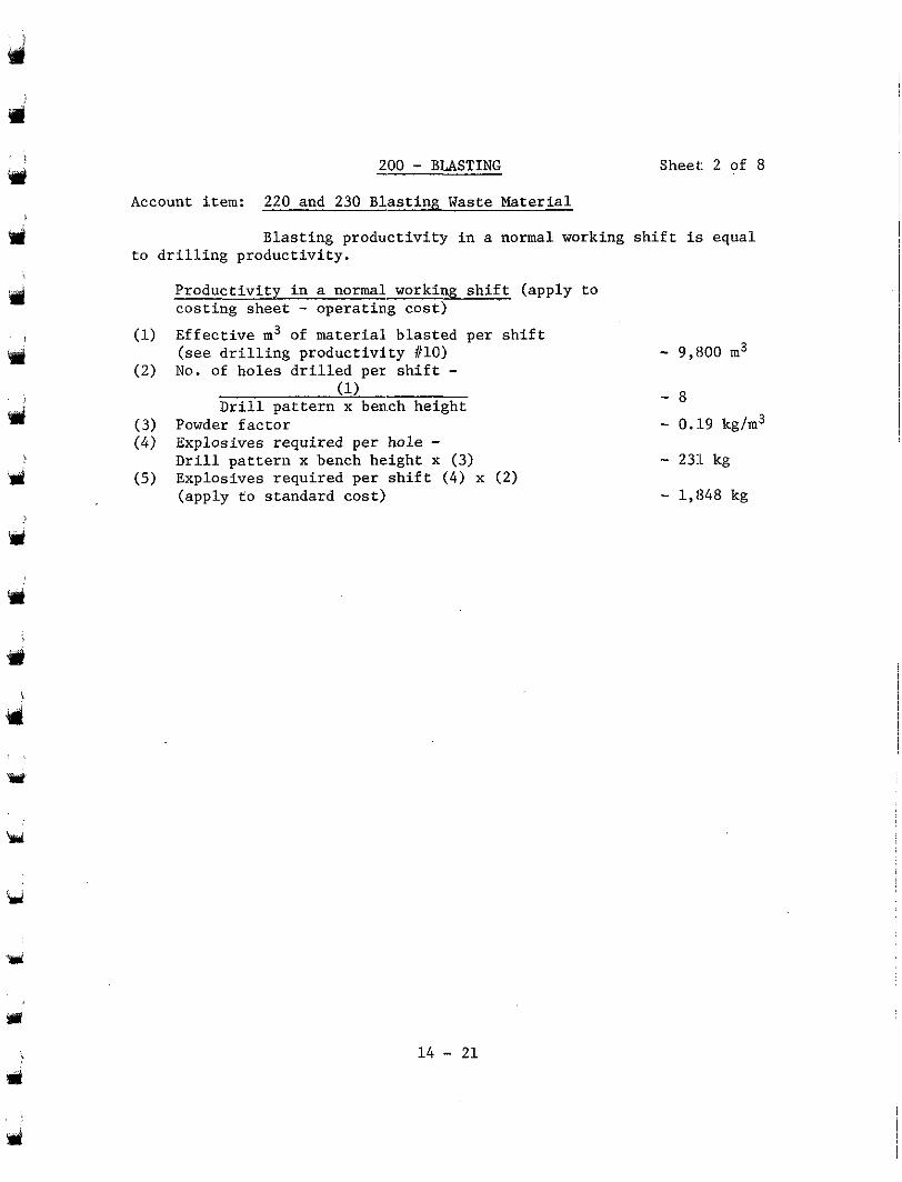
SJ
'd
$9 !
3
- 200 - BLASTING Sheet: 2 of 8
Account item: 220 and 230 Blasting Waste Material
to drilling productivity. Blasting productivity in a normal working shift is equal
Productivity in a normal working shift (apply to costing sheet - 0peratin.g cost) Effective m3 of material blasted per shift (see drilling productivity #lo) No. of holes drilled per shift -
(1) Drill pattern x ben.ch height
Powder factor Explosives required per hole - Drill pattern x bench height x (3) Explosives required per shift ( 4 ) x (2) (apply to standard cost)
- 9,800 m3 - 8 - 0.l9 kg/m3 - 2311 kg
- 1,848 kg
i
i$ 14 - 21
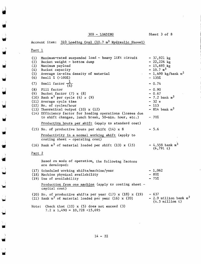
'rd
J
. i
cli
Y
b
300 - LOADING
Account item: 310 Loading Coal (10.7 m3 Hydraulic Shovel)
Part 1
(I) Maximum-rated suspended load - heavy lift circuit (2) Bucket weight - bottom dump (3) Maximum payload (4) Bucket capacity (5) Average in-situ density of material (6) Swell (>loo%) (7) Swell factor - 1
(6) (8) Fill factor (9) Bucket factor (7) x (8) (10) Bank m 3 per cycle (4) x (9) (11) Average cycle time (12) No. of cycles/hour (13) Theoretical output (10) x (12) (14) Efficiency factor for loading operations (losses due
to shift changes, lunch break, 50-min. hour, etc.) Productive hours per sh.ift - (apply to standard cost)
(15) No. of productive hours, per shift (14) x 8 Productivity in a norma.1 working shift (apply to costing sheet - operati.ng cost)
(16) Bank m3 of material 1oa.ded per shift (13) x (15)
Part 2
are developed: Based on mode of operat.ion, the following 'factors
(17) Scheduled working shift:s/machine/year (18) Machine physical availability (19) Use of availability
Production from one mac:& (apply to costing sheet - capital cost)
(20) No. of productive shift:s per year (17) x (18) x (19) (21) Bank m3 of material loaded per year (16) x (20)
Note: Check that (10) x (5) does not exceed (3) 7.2 x 1,490 = 10,728 <15,695
Sheet 3 of 8
- 37,921 kg - 2;!,226 kg - 15,695 kg - 10.7 m3 - 1,,490 kg/bank m3 - 135% - 0.,74 - 0..90 - 0..67 - 7..2 bank m3 - 32 s - 113 - 81.4 bank m3 - 70%
- 5..6
- 4.,558 bank m3 (6,791 t)
- 1,,062 - 80% - 75%
- 6:37 - 2.9 million bank m3
(4.3 million t)
Y
, u 14 - 22
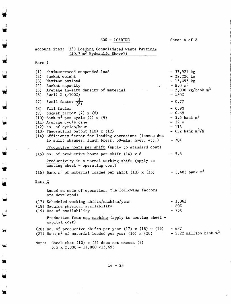
Yd
d
9d
d !
iia
ui Y
k 4
300 - LOADING Account item: 320 Loading Consolidated Waste Partings
(10.7 m3 Hydraulic Shovel)
Part 1
(1) Maximum-rated suspended load (2) Bucket weight (3) Naximum payload (4) Bucket capacity (5) Average in-situ density of material (6) Swell % (>loo%) (7) Swell factor - 1
(6) (8) Fill factor (9) Bucket factor (7) x ( 8 ) (10) Bank m3 per cycle (4) x (9) (11) Average cycle time (12) No. of cyclesfhour (13) Theoretical output (10) x (12) (14) Efficiency factor for loading operations (losses due
to shift changes, lunch break, 50-min. hour, etc.)
Productive hours per shift - (apply to standard cost) (15) No. of productive hours per shift (14) x 8
Productivity in a normal working shift (apply to costing sheet - operating cost)
(16) Bank m3 of material loaded per shift (13) x (15)
Part 2
Based on mode of operation, the following factors are developed:
(17) Scheduled working shifts/machine/year (18) Machine physical availability (19) Use of availability
Production from one machine (apply to costing sheet - capital cost)
(20) No. of productive shifts per year (17) x (18) x (19) (21) Bank m3 of material loaded per year (16) x (20)
Note: Check that (10) x (5) does not exceed (3) 5.5 x 2,000 = 11,000 <15,695
Sheet 4 of 8
- 37,921 kg - 22,226 kg - 15,695 kg - 2,000 kgfbank m3 - 8.0 m3
- 130% - 0.77 - 0.90 - 0.69 - 5.5 bank m3 - 32 s - 11.3 - 622 bank m3/h - 70%
- 5.6
- 3,483 bank m3
- 1,062 - 80% - 751%
- 637 - 2.22 million bank m3
14 - 23
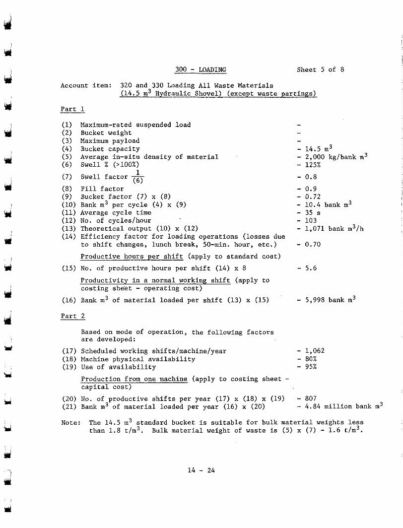
300 - LOADING Sheet 5 of 8
Account item: 320 and 330 Loading All Waste Materials (14.5 m3 Hydraulic Shovel) (except waste partings1
Y
J
Y I
i
url
!
bid
Y
u
Part 1
(1) Maximum-rated suspended load (2) Bucket weight (3) Maximum payload (4) Bucket capacity (5) Average in-situ density of material (6) Swell % (>loo%) (7) Swell factor - 1
(6) (8) Fill factor
(10) Bank m3 per cycle (4) x (9) (9) Bucket factor (7) x (8)
(11) Average cycle time (12) No. of cycles/hour (13) Theoretical output (10) x (12) (14) Efficiency factor for loading operations (losses due
to shift changes, lunch break, 50-min. hour, etc.) Productive hours per shift (apply to standard cost)
(15) No. of productive hours per shift (14) x 8 -
Productivity in a normal working shift (apply to costing she'et - operating cost)
(16) Bank m3 of material loaded per shift (13) x (15)
Part 2
Based on mode of operation, the following factors are developed:
(17) Scheduled working shifts/machine/year (18) Machine physical availa'bility (19) Use of availability
Production from one machine (apply to costing sheet - capital cost)
(20) No. of productive shifts per year (17) x (18) x (19) (21) Bank m3 of material loaded per year (16) x (20)
- - - - 2,000 kg/bank m3 - 14.5 m3 - 125% - 0.8
- 0.72 - 0.9 - 10.4 bank m3 - 35 s - 103 - 1,071 bank m3/h - 0.70
- 5.6
- 5,998 bank m3
- 1,062 - 95% - 80%
- 807 - 4.84 million bank m3
Note: The 14.5 m3 standard bucket is suitable for bulk material weights less than 1.8 t/m3. Bulk material weight of waste is (5) x ( 7 ) - 1.6 t/m3.
14 - 24
Y
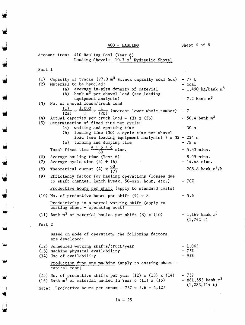
pri
9 1
3
400 - HAULING
Account item: 410 Hauling Coal (Year 6) Loading Shovel: 10.7 m3 Hydraulic Shovel
Part 1
Sheet 6 of 8
(1) Capacity of trucks (77.3 m3 s t ruck capac i ty coa l box) - 7:7 t (2 ) Mater ia l ' to be handled: - coa l
- 1.,490 kg/bank m3
- 7..2 bank m3
(a ) average in -s i tu dens i ty of material (b) bank m3 per shovel load (see loading
equipment ana.lysis) (3) No. of shovel loads/ t ruck load
(1) 1 000 1 ( 2 4
-x- x -- (nearest lower whole number) - 7 (2b) 1 (4) Actual capacity per truck load - (3) x (2b) - 50.4 bank m3 (5) Determination of fixed time per cycle:
(a) wai t ing and spot t ing time (b) loading time (30) x cyc le time per shovel
(c ) tu rn ing and dumping time
- 30 s
load (see 1oa.ding equipment ana lys i s ) 7 x 32 - 224 s - 713 s - 5.53 mins. To ta l f i xed time mins. 60
(6) Average hauling time (Year 6) (7) Average cycle time (5) + (6)
(8) Theoret ical output (4) x - 60 (7)
- 8.95 mins. - 14.48 mins.
- 208.8 bank m3/h
(9) E f f i c i ency f ac to r fo r hau l ing ope ra t ions ( l o s ses due to sh i f t changes , lunch break , 50-min. hour , e tc . ) - 70%
Product ive hours per sh i f t (apply to s tandard cos ts )
(10) No. of product ive hours per sh i f t (9 ) x 8 - 5.6
P roduc t iv i ty i n a normal working s h i f t ( a p p l y t o cos t ing shee t - o p e r a t h g c o s t )
(11) Bank m3 of ma te r i a l hau led pe r sh i f t (8) x (10) - 1,169 bank m3
P a r t 2 ( l , 7 4 2 t )
Based on mode of operat: ion, the following factors are developed:
(12) Scheduled working shif t:s/truck/year (13) Machine p h y s i c a l a v a i l a b i l i t y (14) Use of a v a i l a b i l i t y
- 1,062 - 7:3% - 9.5%
Production from one mat= (apply to cos t ing shee t - c a p i t a l c o s t )
(15) No, of product ive sh i f t s per year (12) x (13) x (14) - 737 (16) Bank m3 of mater ia l hauled in Year 6 (11) x (15) - 861,553 bank m3
Note: Productive hours per annum - 737 x 5.6 = 4 , 1 2 7 ( l ,283 ,714 t )
1 4 - 25
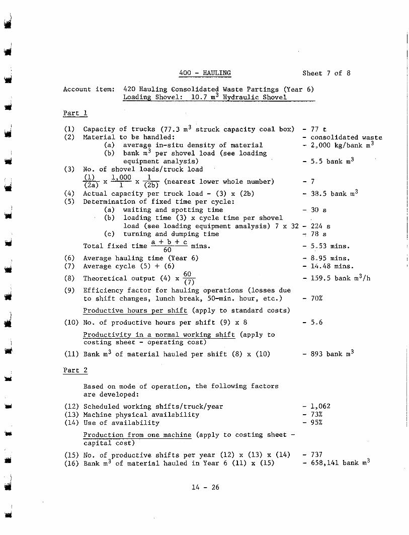
400 - HAULING Sheet 7 of 8
Account item: 420 Hauling Consolidated Waste Partings (Year 6) Loading Shovel: 10.7 m3 Hydraulic Shovel
Part 1
(1) Capacity of trucks (77.3 m3 struck capacity coal box) - 77 t (2) Material to be handled: - consolidated waste
(a) average in-situ density of material - 2:,000 kg/bank m3 (b) bank m3 per shovel load (see loading
equipment analysis) - 5..5 bank m3 (3) No. of shovel loads/tru.ck load
d
Y
f
d
Y
Y
u
(1) 1 000 1 (2a) -x-x- 1 (2b) (ne.arest lower whole number) - 7
(4) Actual capacity per truck load - (3) x (2b) - 38.5 bank m3 (5) Determination of fixed time per cycle:
(a) waiting and spotting time (b) loading time (3) x cycle time per shovel
(c) turning and dumping time
- 30 s
load (see 1oa.ding equipment analysis) 7 x 32 - 224 s
Total fixed time -- a + b f c 60 mins.
(6) Average hauling time (Year 6) (7) Average cycle (5) + (6) ( 8 ) Theoretical output (4) x - ( 9 ) Efficiency factor for bauling operations (losses due
60 (7 )
to shift changes, lunch. break, 50-min. hour, etc.) Productive hours per sbift (apply to standard costs)
(10) No. of productive hours. per shift (9) x 8 -
Productivity in a norma.1 working shift (apply to costing sheet - operating cost)
(11) Bank m3 of material haded per shift ( 8 ) x (10)
Part 2
Based on mode of operat.ion, the following factors are developed:
(12) Scheduled working shift.s/truck/year (13) Machine physical availa.bility (14) Use of availability
Production from one m a c m (apply to costing sheet - capital cost)
(15) No. of productive shifts per year (12) x (13) x (14) (16) Bank m3 of material hauled in Year 6 (11) x (15)
- 78 s
- 5..53 mins.
- 14.48 mins. - 8..95 mins.
- 159.5 bank m3/h
- 70%
- 5..6
- 893 bank m3
- 1,,062 - 73% - 9!5%
- 737 - 658,141 bank m3
14 - 26
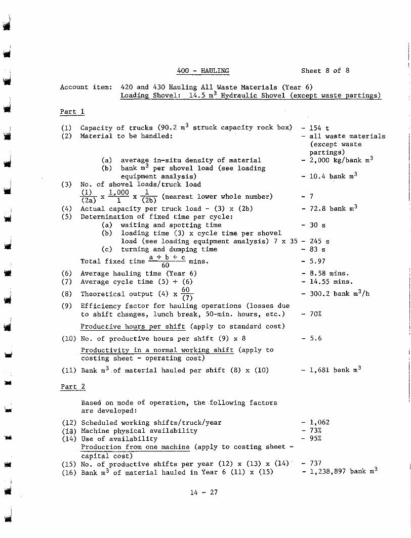
u1
400 - HAULING Sheet 8 of 8
Account item: 420 and 430 Hauling A l l Waste Materials (Year 6) Loading Shove:l: 14.5 m3 Hydraulic Shovel (except waste partings)
P a r t 1
(1) Capacity of trucks (90.2 m3 s t ruck capac i ty rock box) - 154 t (2) Material to be handled: - a l l waste ma te r i a l s
pa r t ings ) (except waste
- 2,000 kg/bank m3 (a ) average in -s i tu dens i ty of ma te r i a l (b) bank m3 per shovel load (see loading
(3) No. of shovel loads / t ruck load (1) 1 000 1 ( 2 4
x " 1 - x - 1 (2b) (nearest lower whole number) - 7
equipment a n a l y s i s ) - 10.4 bank m3
- (4) Actual capaci ty per t ruck load - (3) x (2b) - 72.8 bank m3 (5) Determination of f ixed time per cycle:
(a) wai t ing and spot t ing time (b) loading time (3) x cyc le time per shovel
(c ) tu rn ing and dumping time
- 30 s
load (see loading equipment analysis) 7 x 35 - 245 s - 83 s
- 5.97 Tota l f ixed t ime ~o a + b -I- - c
(6) Average hauling time (Year 6) ( 7 ) Average cycle time (5) -I- ( 6 )
"
- 8.58 mins. - 14.55 mins.
(8) Theoret ical output (4) x - (9) Eff i c i ency f ac to r fo r hau l ing ope ra t ions ( l o s ses due
60 (7)
- 300.2 bank m3/h
to sh i f t changes , l unch b reak , 50-min. hours , e tc . ) - 702
Produc t ive hour s pe r sh i f t - (apply to s tandard cos t )
(10) No. of productive hours .per s h i f t (9) x 8 - 5.6
P r o d u c t i v i t y i n a normal. working s h i f t ( a p p l y t o cos t ing shee t - opera t ing cos t )
(11) Bank m3 .of material h a d e d p e r s h i f t (8) x (10) - 1,681 bank m3
Part 2
Based on mode of ope ra t ion , t he - fo l lowing f ac to r s are developed:
(12) Scheduled working shifts/ truck/year - 1,062 (18) Machine p h y s i c a l a v a i l a b i l i t y (14) Use of a v a i l a b i l i t y
- 73x - 9571
Production from one machine (apply to costing sheet - c a p i t a l c o s t )
(15) No. of productive shifts; per year (12) x (13) x (14) - 73'7 (16) Bank m3 of m a t e r i a l h a d e d i n Year 6 (11) x (15) - 1,238,897 bank m3
d 1 4 - 27
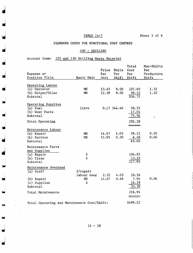
TABLE 14-7 Sheet 1 of 6
STANDARD COSTS ]?OR FUNCTIONAL COST CENTRES
- 100 - DRILLING Account item: 120 and 130 Drilling Waste Material
Price Units Cost Total Man-Shif ts
Expense or Per Per Per Per
Position Title Basic Unit Unit Shift Shift Shift Productive
Operating Labour (a) Operator
Subtotal (b) Helper/Oiler
Operating Supplies (a) Fuel
Subtotal (b) Wear Parts
Total Operating
Maintenance Labour (a) Repair (b) Service Subtotal Maintenance Parts and Supplies (a) Repair
Subtotal (b) Tires
Maintenance Overhead (a) Staff
(b) Repair (c) Supplies Subtotal Total Maintenance
MH 13.45 8.00 107.60 MH
1.32 12.39 8.00 99.12 1.32
206.72
litre 0.17 344.40 . 58.55 17.01 75.56 282.28
MH 14.67 MH 12.95
$ S
$/repair labour hour 2.52
MH 14.67 s
Total Operating and Maintenance Cost/Shift:
14 - 28
I
4.03 59.12 0.50 0.50 6.48 0.06
65.60
104.85 13.10 117.95
4.03 10.16 0.48 7.04 0.06
16.19 33.39 216.94
$499.22
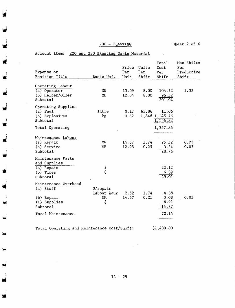
pri
UJ
irl
Y
Y
u
'd
srl
d
200 - BLASTING
Account item: 220 and 230 Blas t ing Waste Mater ia l
Expense o r P r i c e Units Per Per
Sheet 2 of 6
Tota l Man-Shif ts c o s t Per Per Pr'oductive
Pos i t i on T i t l e Bas ic Uni t Uni t Shi f t Shi f t Shi f t
Operating Labour (a) Operator
Sub to ta l (b) Helper/Oiler
MH MH 12.04
13.09
Operating Supplies (a) Fuel l i t re 0.17 (b) Explosives kg 0.62 Sub to ta l
Total Operating
Maintenance Labour (a) Repair MH 14.67 (b) Service MH 12.95 Sub to ta l
Maintenance Parts and Suppl ies (a) Repair (b) Tires Sub to ta l
Maintenance Overhead (a) S t a f f $ / r epa i r
labour hour 2.52 (b) Repair MH 14.67 (c) Suppl ies $ Subto ta l
Total Maintenance
Total Operating and Maintenance Cost/Shift:
8.00 104.72 8.00 96.32
201.04
65.06 11.06 1,848 1,145.76
1,156.82
1,357.86
1.74 25.52 0.25 3.24
28.76
22.12 6.89
29.01
0.21 1 . 7 4 4.38
3.08
14.37 6.91
72.14
$1,430.00
1.32
0.22 0.03
0.03
14 - 29
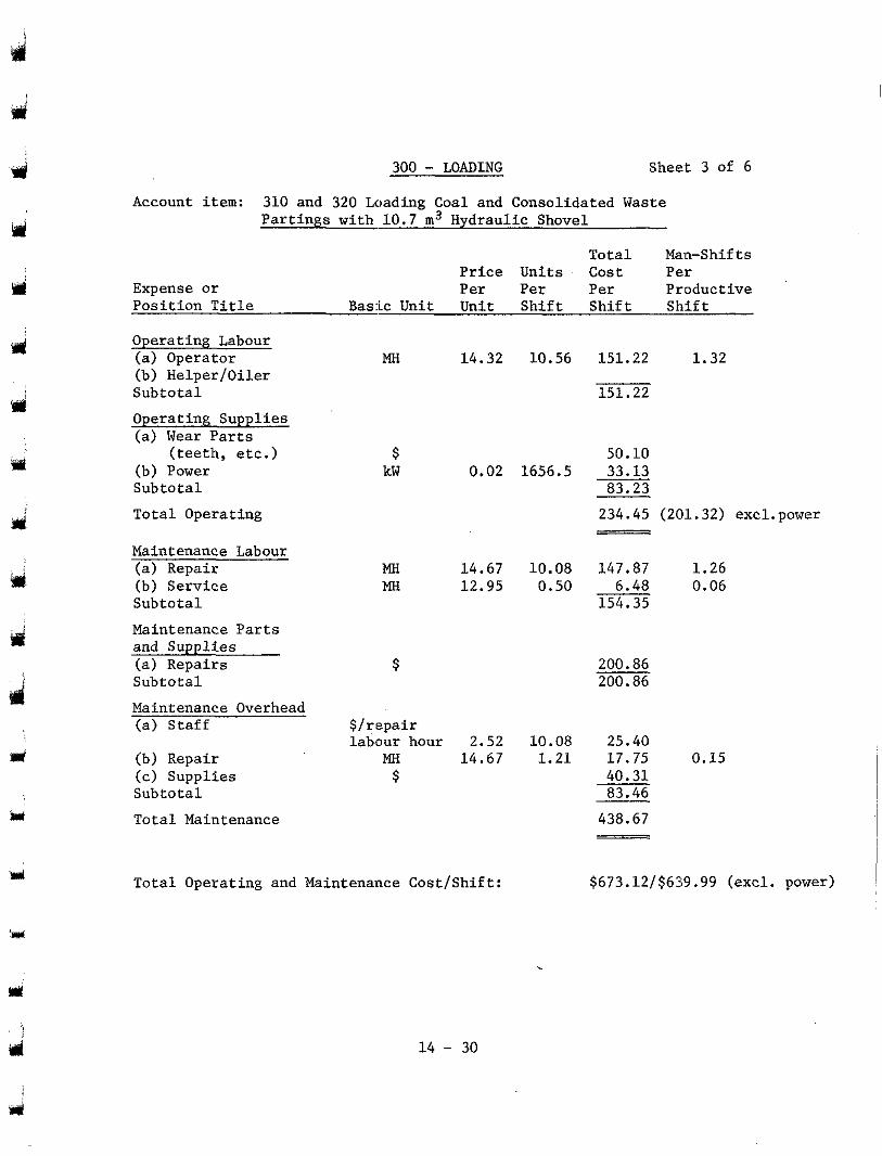
3
u
300 - LOADING Sheet 3 of 6
Account item: 310 and 320 Loading Coal and Consolidated Waste Partings with 10.7 m3 Hydraulic Shovel
Total Man-Shifts Price Units Cost
Expense or Per Per Per
Per Position Title Bask Unit Unit Shift Shift Shift
Productive
Operating Labour (a) Operator
Subtotal (b) Helper/Oiler
Operating Supplies (a) Wear Parts
(b) Power Subtotal Total Operating
(teeth, etc.)
Maintenance Labour (a) Repair
Subtotal (b) Service
Maintenance Parts and Supplies (a) Repairs Subtotal Maintenance Overhead (a) Staff
(b) Repair (c) Supplies Subtotal Total Maintenance
MH 14.32 10.56 151.22 1.32
151.22
$ 50.10 kW 0.02 1656.5 33.13
83.23 234.45 (201.32) excl.power
MH 14.67 10.08 147.87 1.26 MtI 12.95 0.50 6.48 0.06
154.35
$/repair labour hour 2.52 10.08 25.40
438.67
Total Operating and Maintenance Cost/Shift: $673.12/$639.99 (excl. power)
ilsl i
14 - 30
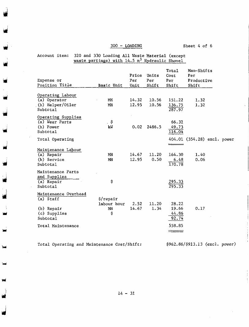
300 - LOADING Sheet 4 of 6
Account item: 320 and 330 Loading All Waste Material (except waste par t ings) with 14.5 m3 Hydraulic Shovel
To ta l Man-Shif ts Price Units Cost Per Per Per
Per Product ive Expense o r
Pos i t i on T i t l e Bask Unit Uni t Shif t Shif t Sh.ff t
Operating Labour ( a ) Operator
Sub to ta l (b) Helper/Oiler
MH 14.32 MH 12.95
Operating Supplies (a) Wear P a r t s $ (b) Power kW 0.02 Sub to ta l
Total Operat ing
Maintenance Labour (a) Repair MH 14.67 (b) Service MH 12.95 Sub to ta l
Maintenance Parts and Suppl ies
Sub to ta l (a) Repair
Maintenance Overhead (a ) S ta f f $ / repa i r
(b) Repair (c) Suppl ies Sub to ta l
Total Maintenance
labour hour 2.52 MH
$ 14.67
Total Operating and Maintenance Cost/Shift:
14 - 31
10.56 151.22 1.32 10.56 136.75
287.97 1.32
2486.5 49.73 66.31
116.04
404.01 (354.28) exc l . power
11.20 164.30 1.40 0.50 6.48 0.06
170.78
11.20 28.22 1.34 19.66 0.17
44.86 92.74
558.85
$962.86/$913.13 (excl. power)
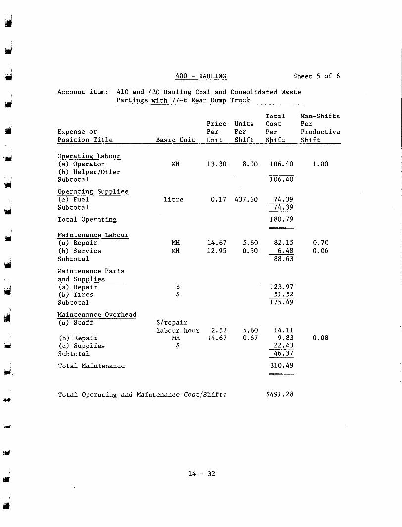
Y
d
d
ri
400 - HAULING Sheet 5 of 6
Account item: 410 and 420 Hauling Coal and Consolidated Waste Partings with 77-t Rear Dump Truck
Total Man-Shifts
Expense or Per Per Per Productive Position Title
Price Units Cost Per
Basic Unit Unit Shift Shift Shift
Operating Labour (a) Operator
Subtotal (b) Helper/Oiler
Operating Supplies (a) Fuel Subtotal Total Operating
Maintenance Labour (a) Repair (b) Service Subtotal
Maintenance Parts and Supplies (a) Repair (b) Ekes Subtotal Maintenance Overhead (a) Staff
(c) Supplies (b) Repair
Subtotal Total Maintenance
i%l 13.30 8.00 106.40 1.00
106.40
litre 0.17 437.60 74.39 74.39 180.79
MH 14.67 5.60 82.15 0.70 MH 12.95 0.50 6.48 0.06
88.63
123.97 51.52 175.49
$/repair labour hour 2.52 5.60 14.11
22.43 46.31
310.49
MH 14.67 0.67 9.83 0.08 $
Total Operating and Maintenance Cost/Shift: $491.28
w 14 - 32
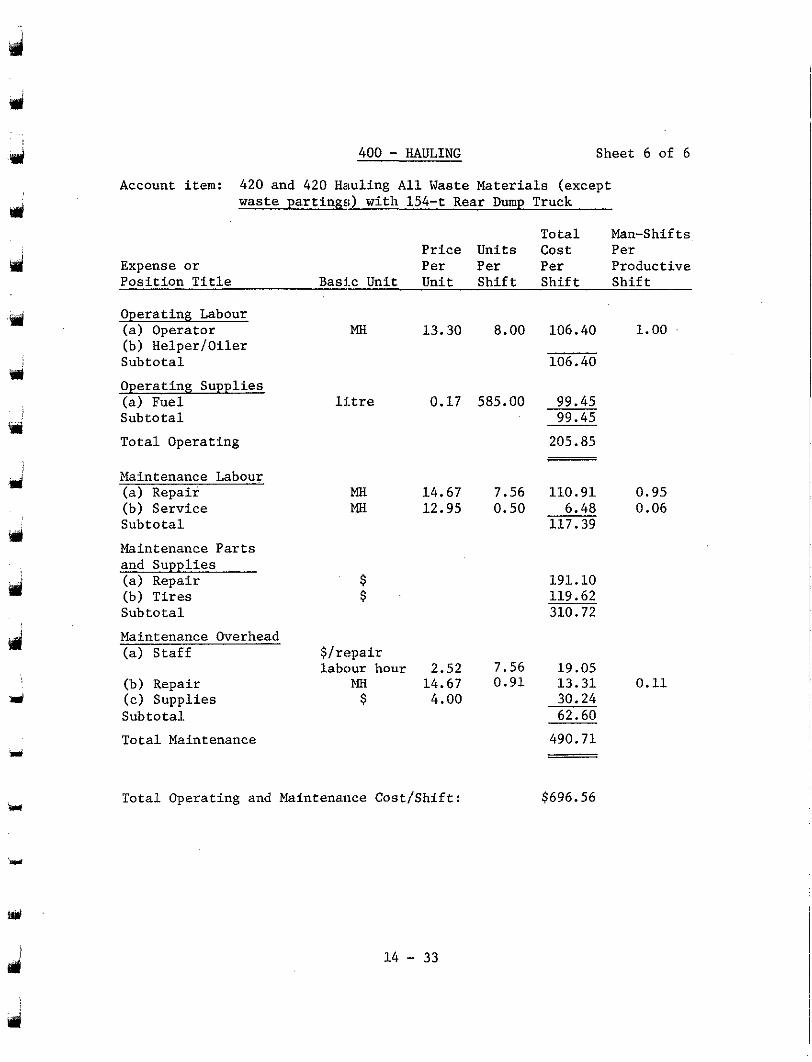
Y
v i i
!d
d
d
400 - HAULING Sheet 6 of 6
Account item: 420 and 420 Hauling A l l Waste Materials (except waste partinpr;) with 154-t Rear Dump Truck
Price Units Cost P e r Total Man-Shifts
Pos i t i on T i t l e Expense o r P e r Per Per Productive
Bas ic Uni t Uni t Shi f t Shi f t Sh: i f t
Operating Labour (a) Operator (b) Helper /Oiler Sub to ta l
MH 13.30 8.00 106.40 1.00
106.40
Operating Supplies (a) Fuel l i t r e 0.17 585.00 99.45 Sub to ta l 99.45
Total Operating
Maintenance Labour (a) Repair (b) Service Sub to ta l
205.85
MH 14.67 7.56 110.91 0.95 MH 12.95 0.50 6.48 0.06
117.39
Maintenance Parts and Supplies (a) Repair $ 191.10 (b) Tires $ 119.62 Sub to ta l 310.72
Maintenance Overhead (a) S ta f f $ / r epa i r . .
labour hour 2.52 7.56 19.05 (b) Repair MH 14.67 0.91 13.31 0.11 (c) Suppl ies $ 4.00 30.24 Sub to ta l 62.60
Tota l Maintenance 490.71
M
w
Total Operating and Maintenance Cost/Shift: u $696.56
1 4 - 33
14.3 CAPITAL COSTS
w
Y
d
scheme was prepared in accordance with the following major cost centres: The c a p i t a l c o s t estimate f o r t h e recommended mining
Engineering and Construction Costs;
Mine Property Development;
Bui ldings and Structures;
Mining Equipment;
Coal Conveying, Crushing and Blending Equipment;
Low-grade Coal Beneficiation Equipment;
Waste Disposal Equipment;
Reclamation and Environmental Protection;
Contingency.
Table 14-9 summarizes the project cash f low of cap. i ta1 costs for these nine major cost centres over the f ive-year pre-product ion period, 35-year production period, and 10-year post-production reclamation per iod. The cash f low of mine equipment c a p i t a l c o s t s was developed according to the system shown i n Figure 14-1. The c a p i t a l c o s t s .and
product iv i ty s tandards p resented in Table 14-6, were t h e main sources of s e r v i c e l i v e s of equipment presented i n Table 14-3, and t h e equipment
input in developing these cash f lows.
ment o f c a p i t a l c o s t s f o r l o a d i n g and haulage equipment. Table 14-8 presents sample calculat ions for the develop-
1 4 - 34
. .
d
tol
14.3.1
14.3.1.1
Description of Costs Included in the Major Cost Centres
Engineering and Construction (Account Code 90000)
The engineering and construction costs include the capital costs of project management and design, pre-production survey and drilling, and construction costs. Included in the constructi.on costs is the operating cost of a construction ramp at $18.00 per man- day. The construction schedule is shown in Section 12.
14.3.1.2 Mine Property Development (Account Code 91000)
costs of the permanent roads in the service area, the mine water supply, sewer and drainage systems, in-pit electrical distribution, fuel distribution station, pit communications (radio and telephone), and the estimated
are the costs of land and mineral rights purchase. costs of site improvements. Not included in the development esti.mates
The mine property development costs are the construction
14.3.1.3 Buildings and Structures (Account Code 92000)
'3
costs of the following:
(1) Administration and Office Building;
(2) Maintenance shops and Warehouse;
(3) Mine Dry;
(4) Mine service buildings;
(5) Bulk Fuel and Lube Storage;
The buildings and structures costs include the capital
14 - 35
UJ
d i
(6) Equipment and furnishings for the buildings during the project life.
basis per square metre of floor area. The cost of these buildings are estimated on a unit cost
struction of off-site housing, or on-site accommodation of mine personnel at any stage of construction or operation.
No allowances have been made for a townsite, the con-
14.3.1.4 Mining Equipment - (Account Code 93000)
capital replacement costs of all mobile mining equipment, auxiliary and The estimated mining equipment costs are the initial and
support equipment, and initia,l spare parts.
J i
14.3.1.5 Coal Conveying, Crushing, and Blending Equipment (Account Code 94000)
J
d
d
The costs in this account include the capital costs of:
- Coal conveyors within the pit; - Truck dump station equipment; - Overland coal conveyor;
- Crushing Plant; - Transfer conveyors, conveyors in the blending area,
weigh scale; stackers, reclaimers, transfer car, sampling system, and
- Initial spare parts; - Construction costs of truck dump stations, overpasses, crusher and transfer houses, conveyor corridors, access roads, and conveyor supports.
14 - 36
Y
iri
I w
P(
.. q@
il
w
14.3.1.6 Low-grade Coal Beneficiation Equipment (Account Code 95000)
The costs in this account include the capital costs of:
- The low-grade coal conveyor within the pit: - Truck dump station equipment; - Low-grade coal plant equipment including screens, crushers, bulk density meters, surge bins and reject conveyors;
- Initial spare parts;
- Construction costs o f the truck dump station, conveyor corridors and supports.
14.3.1.7 Waste Disposal Equipment (Account Code 96000)
of: The estimated waste disposal costs are the capital costs
- Waste conveyors within the pit;
- Truck dump sta.tion equipment; - Overland waste conveyors; - Waste dump tra.nsfer conveyors, shiftable conveyors, portable belt conveyors, trippers, and spreaders;
- Initial spare parts;
- Construction Costs of conveyor foundations and supports, conveyor corridors, service roads, and truck dump stations.
14 - 37
J
14.3.1.8 Reclamation and Environmental Protection (Account Code 97000)
The c o s t s in t : h i s a c c o u n t i n c l u d e t h e i n i t i a l c a p i t a l
and equipment fo r t hese bu i ld ings , and t h e e s t i m a t e d i n i t i a l c a p i t a l and c o s t s of the rec lamat ion complex, including greenhouses, machinery shed,
replacement costs of l igh t vehic les , agr icu l tura l equipment , l abora tory and testing equipment, office equipment, and seed and plant stock.
14.3.1.9 Contingency (Account Code 98000)
Y
Y
Y
j
'd
ment of t he va r i ab le r i sks i nvo lved i n the major cost centres, as well as cons idera t ion of the degree of completeness of cost information, and the l abour por t ion of t h e c o s t .
The contingenc:y allowance was developed following assess-
A low r i s k f a c t o r was applied to mobile mining equipment, conveying equipment, and v e h k l e s , s i n c e it was cons idered poss ib le tha t
be improved upon a t t h e time of purchase. Higher r isk factors w(2re the preliminary manufacturers; ' budget quotations for these items could
appl ied to cos t cen t res invol .v ing h igh labour conten t such as cons t ruc t ion work.
f a c t o r s : The to ta l es t imated cont ingency was based on the :following
Category Contingency
Factor __
A l l equipment employed i n t h e mining opera t ions ; .LO%
Buildings and s t ructures , insurance,
management and engineer ing costs . and cons t ruc t ion cos ts , and p ro jec t
15%
described above, and is not intended to be a provis ion against unfore- The cont ingency a l lowance provides only for those r isks
seeab le r i sks such as foreign exchange f luctuat ions on foreign purchases , l e n g t h y i n d u s t r i a l d i s r u p t i o n s , o r e v e n t s of force majeure of amy type.
1 4 - 38
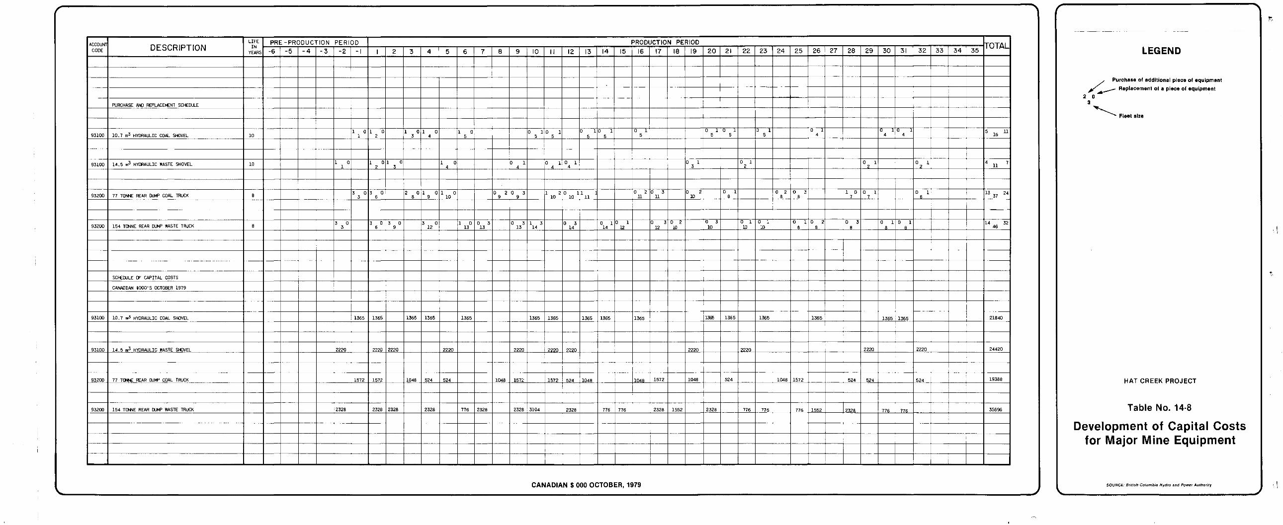
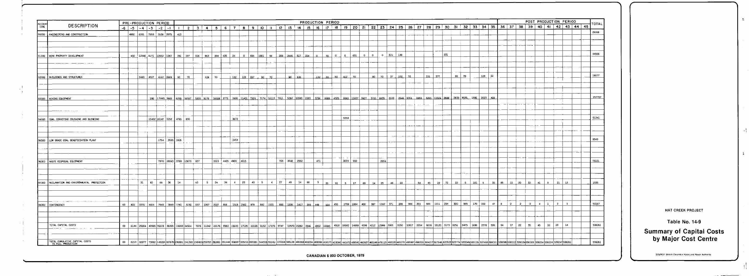
14.4 OPERATING COSTS -
schemes was prepared in accordance with the following major cost centres: The operating cost estimate for the recommended mining
Drilling;
Blasting;
Loading;
Hauling;
Coal-handling System (truck dump stations to powerplant);
Waste-handling System dumps) ;
Auxiliary Equfpment;
Power;
General Mine Ilxpense;
Overhead;
Royalties;
Contingency;
(truck dump stations to was'te
Contractor's Allowance.
Table 14-11 summarizes the project cash flow of operating costs for these 13 major cost centres over the five-year pre-production period, 35-year production period, and 10-year post-production reclamation period. Pre-production operating costs were not transferred to capital costs. The cash flow of operating costs was developed according to the system shown in Figures 14-1!, 14-2, and 14-3. Operating cost estimating
developing these cash flows. criteria shown in Tables 14-4 to 14-7 were the main sources of input in
the functional cost centres, drilling, blasting, loading, haulin,g, and waste-handling.
Table 14-10 shows the development of operating co,sts for
14 - 41
1
id
ul
14.4.1
14.4.1.1
Descr ipt ion of Costs Included i n t h e Major Cost C t e
D r i l l i n g and Blasting (Account Codes 100 and 200)
f o r d r i l l i n g and blast ing approximately 10% of t h e waste ma te r i a l s mined from t h e open p i t . Tests on t h e s t r e n g t h of t h e waste and coa l ma te r i a l s i n t h e Hat Creek Deposi t indicate that the hydraul ic shovels employed
wi th no p r i o r b l a s t i n g . An allowance has therefore been made only f o r fo r l oad ing ope ra t ions w i l l be capable of digging almost a l l materials
i s o l a t e d areas of consol idated waste materials t h a t would r equ i r e b l a s t ing .
The cos ts in t .hese accounts inc lude the opera t ing cos ts
14.4.1.2 Loading and H a . (Account Codes 300 and 400)
the hydraul ic shovels and the waste and coa l rear dump t rucks fox the The c o s t s i n t:hese accounts are t h e c o s t s of opera t ing
loading and hauling of coal and waste ma te r i a l s t o t he t ruck un load ing
by sc rape r s as t h e p i t expands. I n add i t ion , s c rape r s w i l l remove 2.2 s ta t ions . Provis ion has been made fo r t he con t inua l removal of t o p s o i l
mi l l i on bank m3 of overburden in t he p re -p roduc t ion pe r iod t o e s t ab l i sh sui table working benches for the hydraul ic shovels and t rucks.
14.4.1.3 Coal and Waste-handling Systems (Account Codes 500 and 600)
Material-handl ing costs are the opera t ing cos ts incur red i n conveying waste t o t h e w a s t e dumps and coa l material t o t h e power- plant . These costs can be broken into the fol lowing components:
1. Conveying Waste
system and the dump-handling system. The c o s t s of r e loca t ing t he dump- conveying systems a s t h e dumps are developed are a lso inc luded .
This covers the operat ing cost of the waste-conveying
1 4 - 42
d I
ei
ui
3
md
2. Conveying Coal
This includes the operating costs of the inclined coal conveyor, truck dump stations, the crushing plant, the overland conveyor to the generating station, and the low-grade coal-handling equipment.
3. Coal Stockpiling and Blending
This includes the operating costs of the stackers, reclaimers, conveyors, and clean-up equipment within the stockpiling and blending area.
14.4.1.4 Auxiliary Equ:Lpment (Account Code 700)
This includes the operating costs of front-end loaders, dozers, graders, small trucks, compactors, and traxcavators employed in a wide variety of operations, which include embankment construction for the waste dumps, causeway construction, levelling on dumps, pushing and compacting stockpiles, bench pioneering, clean-up work, and assisting
construction of the Medicine Creek Dump in Years 12, 13, and 14. loading and hauling equipment. These costs also allow for the initial
14.4.1.5 Power (Account Code 800)
and material-handling equipment. The power costs were then developed based on a rate of 20 mil.ls/'kW.h.
The annual kw'h consumption was determined f o r the shovels
14.4.1.6 General Mine Expense (Account Code 900)
m
14 account items which are described below: The general mine expense includes the operating costs of
3
J I
14 - 43
1
d
1. Pit Dewatering and Drainage
This provides for the installation, operation, and maintenance of the pit dewatering well system and in-pit sumps. Two well systems are required, the first to operate from the pre-production period to Year 15, and the second system to be phased in between Year 10 and Year 15 as the first well system is mined out. Costs allow for repair and replacement of pumps, piping, tankage, well monitoring, and relocation costs of headers and piping as required to support pit: development.
2. Electrical Maintenance
This includes the cost of repairs, routine maintenance, and periodic moves of the in-pit overhead power distribution system, power distribution system of the dumps, and dewatering. This account
handling, repair, and replacement of trailing cables for shovels, also includes the maintenance of all site electrical services and the
conveyors, stackers, and reclaimers.
3. Road Construction and Maintenance
This includes the costs of digging, loading, hauling, placing, and compacting suitable road bases and surface materials, and the additional costs of crushing road surface materials as required for the construction of roads in and around the pit and dumps. These roads are necessary for truck and conveyor access. These costs also allow for snow removal and spreading calcium chloride on all roads.
4 . Mine Service Vehicles and Equipment
This includes the costs of operating mine service vehicles
vulcanizing equipment, steam cleaners, lo-boy and hi-boy, Hiab cranes, such as cranes, service trucks, tire truck, mobile cable reelers:,
and forklifts.
5. Field Lubrication/Fuelling
This includes the cost of operating labour and supplies, and repair labour and parts for the operation of the main fuel dump and in-pit fuelling station. Also included are the operating costs of fuel and lube trucks.
6. Reclamation and Environmental Protection
This includes the costs of staff, maintenance of green- houses and storage buildings, stripping and stockpiling of surface
i
i i
d
14 - 44
3
d
i
d
ud
d
d
i
u
media, revegetation and subsequent maintenance. soils, surface regrading, placement of buffer materials and growth
7. Mine Supervision
superintendent, shift supervisors, shift foremen, together with steno- This provides :€or the salaries and expenses of the mine
graphic and clerical personne.1.
8. Mine Engineering and Geology
This includes .the salaries and expenses of the super- intendent of mine engineering, pit engineer, planning engineers, senior mine geologist, geologists and technicians, survey supervisor and crews, samplers, coal-quality contro.1 technicians, together with stenographic and clerical personnel.
9. Maintenance Engineering
This includes the salaries and expenses of the main-
engineer, an electrical engineer, and draftsmen; the electrical main- tenance superintendent; the design group, consisting of a mechanical
and shift foremen; and the clerical and stenographic staff required in tenance supervisors, consisting of the chief electrician, shop foremen,
have been.allocated to the maintenance costs of the mine equipment or support of these functions. All other costs for maintenance personnel
are included in the account item, "Electrical Maintenance".
10. Mine Communications
This includes the salaries of dispatchers and repair
cost of truck and portable radios. technicians, the costs of radio repair parts, and the annual replacement
11. Mine Transportation I
personnel buses providing daily transport from the dry to the mine. This includes the operating and maintenance costs of
12. Mine Transportation I1
This includes the operating costs of light vehicles assigned to the mine supervisory and technical personnel.
14 - 45
13. Mine Tra:ining
d
training officers, the wages of hourly paid personnel while in training, the costs of training supplies, staff supervisory training and courses.
This provides for the salaries and expenses of mine
14. Close-Spaced In-Pit Drilling
for quality-control drilling. This includes the cost of operating drilling equipment
14.4.1.7 Overhead (Account Code 1000)
following groups:
(1) Management ;
(2) Administration;
(3) Administration Services;
(4) Administration Site Services;
(5) Human Resources;
(6) Local Taxes and Insurance.
Overhead costs comprise the operating costs of the
These six groups are described below.
1. Management Group
This provides for the salaries and expenses of the mine manager, assistant mine manager, supervisor of industrial engineering, industrial and contract engineers, public relations officer, chief chemist, assayers, together with stenographic and secretarial personnel.
2. Administration
This provides for the salaries and expenses of the administration superintendent, accountants, purchasing agents, expe- ditors, warehouse supervisor, stores foremen, and the clerical and stenographic staff required .in support of these functions.
14 - 46
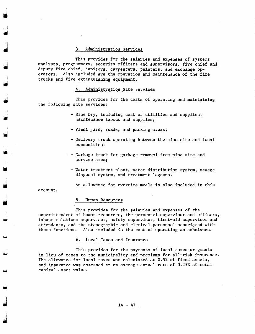
d 3. Adminis t ra t ion Services
This p rovides for the salaries and expenses of systems a n a l y s t s , programmers, secur:Lty o f f i c e r s and supe rv i so r s , f i r e ch i e f and d e p u t y f i r e c h i e f , j a n i t o r s , c a r p e n t e r s , p a i n t e r s , and exchange op- erators . Also included are the ope ra t ion and maintenance of the f i r e t rucks and f i re ext inguishing equipment .
4. Administration S i t e Serv ices
This p rovides for the cos ts of operating and maintaining the fo l lowing s i te se rv ices :
- Mine Dry, inc:tuding cos t of u t i l i t i e s and supp l i e s , maintenance labour and supplies;
- Plant yard, roads, and parking areas;
- Delivery truck operating between the mine s i te and l o c a l communities;
- Garbage truck for garbage removal from mine s i te and s e r v i c e area;
- Water treatment plant , water dis t r ibut ion system, sewage disposal system, and treatment lagoons.
An allowance for overtime meals i s a l so inc luded Ln t h i s account.
5. Human Reso-
This p rovides for the salaries and expenses of t h e superintendent of human resources , the personnel supervisor and o f f i c e r s ,
a t t endan t s , and the s tenographic and clerical personnel associated with l abour r e l a t ions supe rv i so r , s a fe ty supe rv i so r , f i r s t - a id supe rv i so r and
these funct ions. Also included i s the cos t of operat ing an ambulance.
6. Local Taxes and Insurance
This p rovides for the payments of l o c a l t a x e s o r g r a n t s i n l i e u of t axes t o t he mun ic ipa l i t y and premiums fo r a l l - r i sk i n su rance . The a l lowance for loca l t axes was ca l cu la t ed a t 0.5% of f ixed assets, and insurance was assessed ai: an average annual rate of 0.25% of t o t a l c a p i t a l asset value.
d
ri
d r
U
ri
Y
1 4 - 47
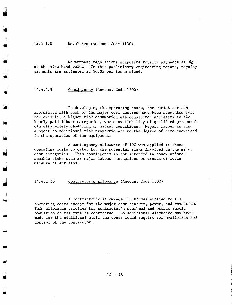
d
d
ul
d
m
14.4.1.8 Royalties (Account Code 1100)
of the mine-head value. In this preliminary engineering report, royalty payments are estimated at $0.35 per tonne mined.
Government regulations stipulate royalty payments as 3%
14.4.1.9 Contingency (Ascount Code 1200)
In developing the operating costs, the variable risks associated with each of the major cost centres have been accounted for. For example, a higher risk assumption was considered necessary in the hourly paid labour categories:, where availability of qualified personnel can vary widely depending on market conditions. Repair labour is also subject to additional risk proportionate to the degree of care exercised in the operation of the equipment.
A contingency allowance of 10% was applied to these operating costs to cater for the potential risks involved in the major cost categories. This contingency is not intended to cover unfolre- seeable risks such as major 1.abour disruptions or events of force majeure of any kind.
14.4.1.10 Contractor's Allowance (Account Code 1300)
A contractor's allowance of 10% was applied to all operating costs except for the major cost centres, power, and royalties. This allowance provides for c:ontractor's overhead and profit should
made for the additional staff the owner would require for monitoring and operation of the mine be contracted. No additional allowance ha!; been
control of the contractor.
d 14 - 48
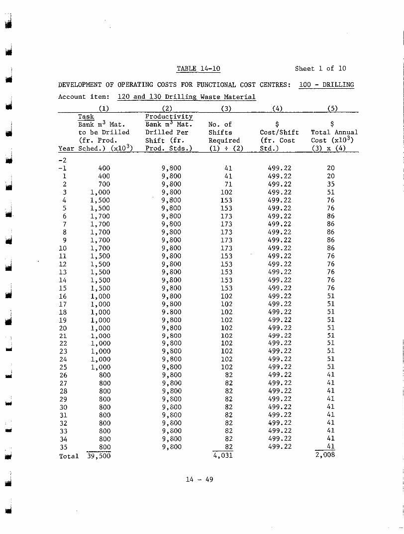
TABLE 14-10 Sheet: 1 of 10
DEVELOPMENT OF OPERATING COSTS FOR FUNCTIONAL COST CENTRES: 100 - DRILLING Account item: 120 and 130 Drilling Waste Material
(1) (2) (3) (4) (5) Task Bank m3 Mat.
Productivity Bank m3 Mat. No. of $ $
to be Drilled Drilled Per Shifts (fr. Prod.
Cost/Shift Total Annual Shift (fr. Required (fr. Cost Cost (x103)
Year Sched.) (x103) Prod. Stds.) (1) i (2) Std.) (3) x (4) -2 -1 1 2
4 3
5 6 7 8
10 9
11 12 13 14 15 16 17 18 19 20 21 22 23 24 25 26 27 28 29 30 31 32 33 34 35
400 400 700
1,500 1,000
1,500 1,700 1,700 1,700 1,700 1,700 1,500 1,500 1,500 1,500 1,500 1,000 1,000 1,000 1,000 1,000 1,000 1,000
1,000 1,000
1,000 800
800 800
800 800 800 800 800 800 800
Total 39,500
9,800 9,800 9,800
9,800 9,800
9,800 9,800 9,800 9,800 9,800 9,800 9,800 9,800 9,800 9,800 9,800 9,800 9,800 9.800 9,800 9,800 9,800 9,800 9,800 9,800 9,800 9,800 9,800 9, 800 9, SO0 9,800 9,800 9,800 9,800 9, El00
41 41 71
153 102
153 173 173 173 173 173 153 153 153 153 153 102 102 102 102 102 102 102 102 102 102 82 82 82 82 82 82 82 82 82
9, El00 82 4,031 -
14 - 49
499.22 20 499.22 20 499.22 35 499.22 51 499.22 76 499.22 76 499.22 86 499.22 86 499.22 86 499.22 86 499.22 86 499.22 76 499.22 76 499.22 76 499.22 76 499.22 76 499.22 51 499.22 51 499.22 51 499.22 51 499.22 51 499.22 499.22
51 51
499.22 51
~. ~
499.22 51 499.22 51 499.22 41 499.22 41 499.22 41 499.22 41 499.22 41 499.22 41 499.22 41 499.22 41 499.22 41 499.22 41
2.008
~~
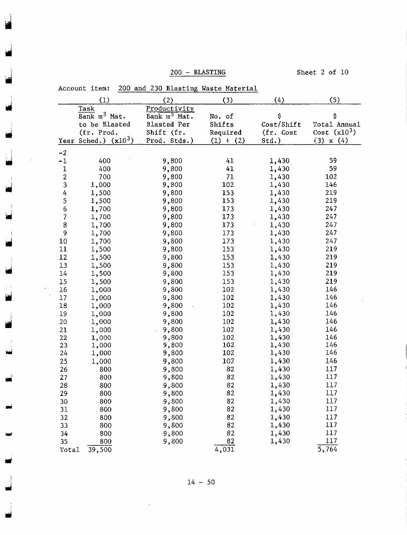
- 200 - BLASTING Sheet: 2 of 10
Account item: 200 and 230 Blasting Waste Material
(1) (2) (3) (4) (5) - Task Bank m3 Mat.
Productivity Bank m3 Mat. No. of $ $
to be Blasted Blasted Per Shifts Cost/Shift Total Annual (fr. Prod. Shift (fr. Required (fr. Cost Cost ~ ~ 1 0 3 )
Year Sched.) (x103) Prod. Stds.) (1) t (2) Std.) (:3) x (4)
-2 -1 1 2
4 3
5 6 7 8 9
10 11 1 2 13 14 15 16 1 7 18 19 20 21 22 23 24 25 26 27 28 29 30 31 32 33 34 35 Total
400 400
1,000 7 00
1,500 1,500 1,700 1,700 1,700 1,700 1,700 1,500 1,500 1,500
'1,500 1,500
1,000 1,000 1,000 1,000 1,000 1,000 1,000 1,000 1,000 1,000
800 800 800 800 800 800 800 800 800 800
39,500
9,800 9,800 9,800 9,800 9,800 9,800 9,800 9,800 9,800 9,800 9,800 9,800 9,800 9,800 9,800 9,800 9,800 9,800 9,800 9,800 9,800
9,800 9,800
9,800 9,800 9,800 9,800 9,800 9,800 9,800 9,800 9,800 9,800 9,800 9,800 9 , El00
14 - 50
41 41
102 71
153 153 173 173 173 173 173 153 153 153 153 153 102 102 102 102 102 102 102 102 102 102
82 82
82 82
82 82 82 82 82 82
4,031
1,430 1,430 1,430 1,430 1,430 1,430 1,430 1,430 1,430 1,430 1,430 1,430 1,430 1,430 1,430 1,430 1,430 1,430 1,430 1,430 1,430 1,430 1,430 1,430 1,430 1,430 1,430 1,430 1,430 1,430 1,430 1,430 1,430 1,430 1,430 1,430
59 59
102 146 219 219 247
247 247
247 247 219 219 219 219 219 146 146 146 146 146 146 146 146 146 146 1 1 7 117
117 117
117 117
117 1 1 7 1 1 7 1 1 7
5,764
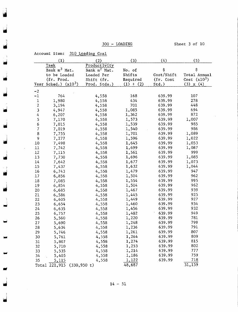
d
d
d
i
Y
Y
300 - LOADING Sheer 3 of 10
Account item: 310 Loading Coal - (1) ( 2 ) ( 3 ) ( 4 ) ( 5 )
Task Bank m 3 Mat.
Product.ivity Bank m3 Mat. No. of $ $
to be Loaded Loaded Per Shifts Cost/Shift 'Total Annual (fr. Prod. Shift (fr. Required (fr. Cost Izost (x103)
Year Sched.) (x103) Prod. Stds.) (1) f ( 2 ) Std.) ( 3 ) x ( 4 )
-2 -1 1 2
4 3
5 6 7 8
10 9
11 12 1 3 14 1 5 16 17 18 19 20 2 1 22 23 24 25 26 27 28 29 30 31 32 33 34
764 1,980 3,194 4,947 6,207 7 , 1 7 0 7 ,015 7,019 7 ,755 7,277 7,498 7 , 7 4 2 7 , 1 1 5 7,730 7 ,642 7,437 6,743 6,856 7 ,085 6,854 6 ,685 6,586 6,605 6 ,654 6,635
5,560 6,757
5 ,690 5,634 5,746 5,761 5,807 5,710 5.535
4,558 4,558 4 ,558 4 ,558 4 ,558 4 ,558 4 ,558 4 ,558 4,558 4 ,558 4,558 4,558 4 ,558 4 ,558 4 ,558 4 ,558 4,558 4 , ii58 4,558 4 ,558 4,558 4,558 4 , Ii58 4 ,558 4 ,558 4 ,558 4 ,558 4 ,558 4 ,558 4,558 4,558
4 , fi58 4,558
4.558 5.405 4.558
35 Total 221,915 (330,950 t)
5 , 1 1 5 4 ; 5 5 8 ~I ~~
434 168
7 0 1
1 , 3 6 2 1,085
1,539 1,573
1 ,540 1 , 7 0 1 1,596 1 ,645 1 ,699 1 , 5 6 1 1,696 1,677 1 ,632 1,479 1 ,504 1,554 1 ,504 1,467 1,445 1,449 1 ,460 1,456 1 ,482 1 ,220
1,236 1 ,248
1,261 1,264 1 ,274 1 ,253 1 ,214 1,186 1 ,122
48,687
639.99 639.99 639.99 639.99 639.99 639.99 639.99 639.99 639.99 639.99 639.99 639.99 639.99 639.99 639.99 639.99 639.99 639.99 639.99 639.99 639.99 639.99 639.99 639.99 639.99 639.99 639.99 639.99 639.99 639.99 639.99 639.99 639.99 639.99 639.99 639.99
107
448 278
694 872
1,007 985 986
1,089
1 , 0 5 3 1,022
1,087 999
1,085 1 ,073 1,044
947 962 995 962 939 925 927
932 934
949 7 8 1 799 7 9 1 807 809 815 802 777 759 718
31,159 .-
14 - 51
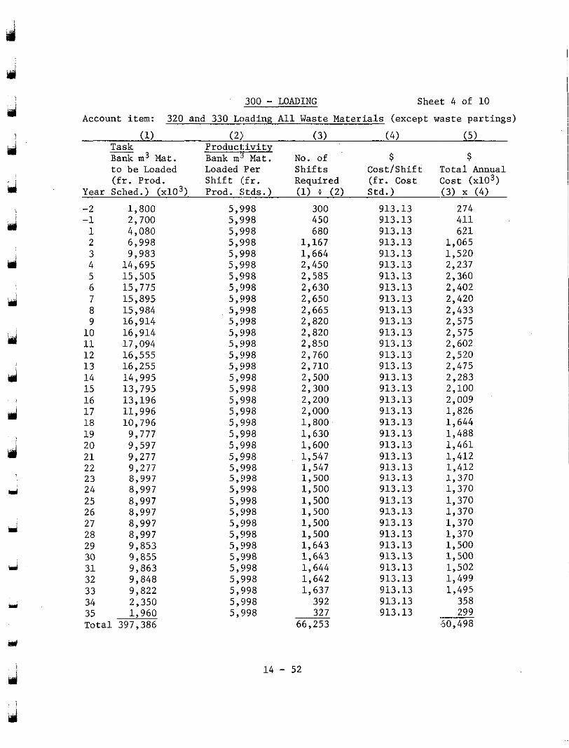
300 - LOADING Sheet 4 of 10
Account item: 320 and 330 Loading A l l Waste Materials (except waste par t ings)
(1) (2) (3) (4) (5) Task Product- Bank m3 Mat. Bank m; Mat. No. of $ $ t o be Loaded Loaded Per S h i f t s Cos t /Shi f t Tota l Annual ( f r . Prod. S h i f t ( f r . Required ( f r . Cos t Cost (x103)
Year Sched.) (x103) Prod. Stds.) (1) i (2) Std.) (3) x (4)
-2 -1 1 2
4 3
5 6 7 8
10 9
11 1 2 13 14 15
17 16
18 19 20 21 22 23 24 25 26 27 28 29 30 31 32 33 34
1,800 2,700 4,080 6,998
14,695 9,983
15,505 15,775 15,895 15,984 16,914
17,094 16,914
16,555 16,255 14,995 13,795 13,196 11,996 10,796
9,777 9,597 9,277 9,277 8,997 8,997 8,997 8,997 8,997 8,997 9,853 9,855 9,863 9,848 9,822 2.350
5,998 5,998 5,998 5,998 5,998 5,998 5,998 5,998 5,998
5,998 5,998
5,998 5,998
5,998 5,998 5,998 5,998 5,998 5,998 5,998 5,998 5,998 5,998 5,998 5,998 5,998 5,998 5,998 5,998 5,998 5,998 5,998 5,998 5,998 5,998 5.998
35 1;960 5; 998 To ta l 397,386
300 450
913.13 913.13
680 913.13 1,167 1,664
913.13 913.13
2,450 913.13 2,585 913.13 2,630 913.13 2,650 913.13 2,665 913.13 2,820 913.13 2,820 913.13 2,850 913.13 2,760 913.13 2,710 913.13
2,300 2,500 913.13
913.13 2,200 913.13
1,800 2,000 913.13
913.13 1,630 913.13 1,600 913.13 1,547 913.13 1,547 1,500
913.13
1,500 913.13 913.13
1,500 913.13 1,500 913.13 1,500 913.13 1,500 913.13 1,643 913.13 1,643 913.13 1,644 913.13 1,642 913.13 1,637 913.13
392 913.13 327 913.13
66,253
14 - 52
411 274
621 1,065 1,520 2,237 2,360 2,402 2,420 2,433 2,575 2,575 2,602 2,520 2,475 2,283
2,009 1,826 1,644 1,488 1 ,461 1,412
1,370 1,412
1,370 1,370 1,370 1,370 1,370 1,500 1,500 1,502 1,499 1,495
358 299
60,498
2,100
.-
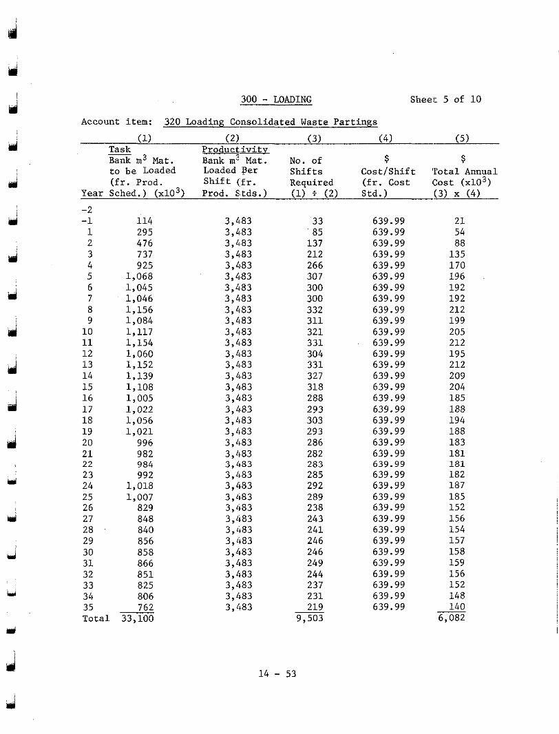
300 - LOADING Sheet 5 of 10
Account item: 320 Loading Consolidated Waste Pa r t ings
(1) (2) (3) (4) (5) Task Bank m3 Mat.
Product- Bank m3 Mat. No. of $ $
t o b e Loaded Loaded per S h i f t s C o s t / S h i f t T o t a l Annual ( f r . P rod . Sh i f t ( f r . Required (fr . Cost 1:ost (x103)
Year Sched.) (x103) Prod. S,tds.) (1) i (2) Std.) (3) x (4) -2 -1 1 2 3 4 5 6 7 8
10 9
11 12 13 1 4 15 16 1 7 18 1 9 20 21 22 23 24 25 26 27 28 29
31 30
32 33 34 35 Total
114 295 476 737 9 25
1,068 1,045 1,046 1,156 1,084 1 , 1 1 7 1,154 1,060 1,152 1,139 1,108 1,005 1,022 1,056 1,021
996 982 984 992
1,018 1,007
829 848 840 856 858 866 851 825 806 762
33,100
3,483 3,4.83 3,483 3,483 3,483 3 , M 3 3,483 3,483 3,483 3 , L183 3,483 3,483 3, /I83 3,483 3,483 3,483 3,483 3,483 3,483 3,483 3,483 3,483 3 , 4 8 3 3,483 3,483 3,483 3,483 3,483 3,483
3,483 3,483
3,483 3,483 3,483 3,483 3,483
33 85
137 212 266 307 300 300 332 311 321 331 304 331 327 318 288 293 303 29 3 286 282 283 285 292 289 238 243 241 246 246 249 244 237
219 231
9,503
639.99 639.99 639.99 639.99 639.99 639.99 639.99 639.99 639.99 639.99 639.99 639.99 639.99 639.99 639.99 639.99 639.99
639.99 639.99
639.99 639.99 639.99 639.99 639.99 639.99 639.99 639.99 639.99 639.99 639.99 639.99 639.99 639.99 639.99 639.99 639.99
21 54
135 88
170 196 192 192 212 199 205 212 195 212 209 204 185 188 194 188 183 181
182 181
187 185 152 156 154 157 158 159 156 152 148 140
6,082
1 4 - 53
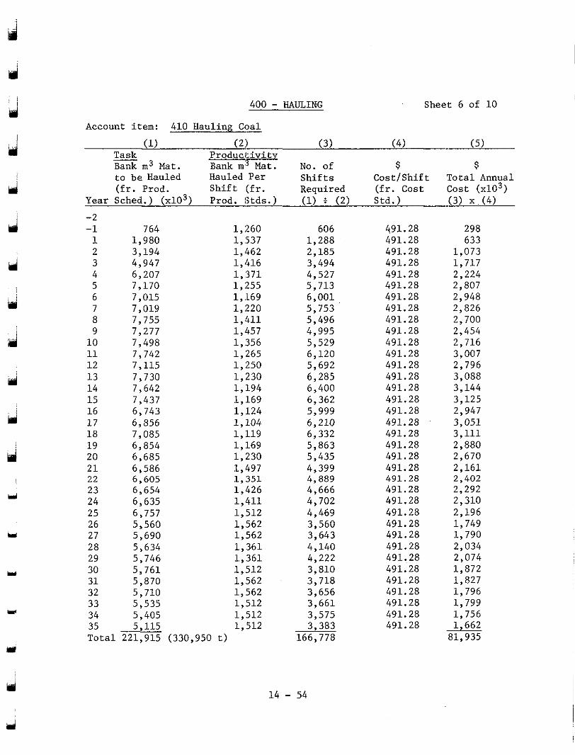
ij
J
d
Y
J
Y
L
H
Y
hi
400 - HAULING Sheet 6 of 10
Account item: 410 Hauling Coal - (1) ( 2 ) ( 3 ) ( 4 ) ( 5 )
Task Bank m3 Mat.
Producl i v i t Bank m Mat. NO. of $ $
t o be Hauled Hauled Per S h i f t s Cos t /Shi f t To ta l Annual ( f r . Prod . S h i f t ( f r . Required ( f r . Cost Cost ~ 0 3 )
Year Sched.) ( d o 3 ) Prod. 8tds . ) (1) t ( 2 ) Std . ) ( 3 ) x . ( 4 )
-2 -1 1 2
4 3
5 6 7
9 8
1 0 11 1 2 1 3 1 4 15
1 7 16
1 8 1 9 20 2 1 22 23 24 25
27 26
28 29 30 31 32 33 34
764 1 ,980 3 ,194 4,947 6,207 7,170 7,015 7,019 7,755 7,277 7 ,498 7,742 7,115 7,730 7,642
6 ,743 7,437
6 ,856 7 ,085 6 ,854 6,685 6,586 6,605 6 ,654 6,635 6,757 5,560 5 ,690 5,634
5 ,761 5,746
5,870 5,710 5.535
1 ,260 1,537 1 ,462 1,416 1 ,371 1 ,255 1, ,169 1 ,220 1 , 4 1 1 1,457 1 ,356 1 ,265 1 ,250 1,230 1 ,194 1,169 1 , 1 2 4 1 , 1 0 4 1 ,119 1 ,169 1,230 1,497 1 ,351 1 ,426 1 ,411 1,512 1 ,562 1 ,562 1 ,361
1,512 1 , 3 6 1
1,562 1 ,562 1.512
. .
35 Tota l 221,915 (330,950 t )
5 ; 405 1,512 5,115 1,512
606 1 ,288 2,185 3,494 4,527 5 ,713 6 ,001 5 ,753 5 ,496 4,995 5,529 6 ,120 5,692 6,285 6,400 6,362 5,999 6 ,210 6,332 5 ,863 5,435 4,399 4,889 4,666 4,702 4,469 3,560 3,643 4,140 4,222
3,718 3,810
3,656 3,661 3,575 3,383
166,778
491.28 491.28 491.28 491.28 491.28 491.28 491.28 491.28 491.28 491.28 491.28 491.28 491.28 491.28 491.28 491.28 491.28
491.28 491.28
491.28 491.28 491.28 491.28 491.28 491.28 491.28 491.28 491.28 491.28
491.28 491.28
491.28 491.28 491.28 491.28 491.28
298 633
1 ,073 1,717 2,224 2,807 2,948 2,826 2,700 2,454 2,716 3,007 2,796 3,088 3,144 3,125 2,947 3,051 3 ,111 2,880 2,670 2 ,161 2,402 2,292 2,310 2,196 1 ,749 1 ,790 2,034 2 ,074 1 ,872 1,827
1 ,799 1 ,796
1,756 1,662
81,935
1 4 - 54
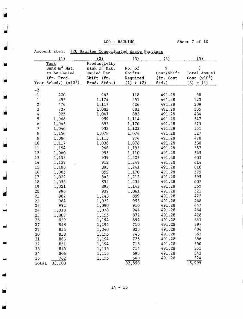
. .
Y
iri
PI
400 - HAULING Sheet: 7 of 10
Account item: 420 Hauling Consolidated Waste Pa r t ings
(1) (2) (3) (4) (5) Task Bank m3 Mat.
Product iv i ty Bank m5 Mat. No. of $ $
t o b e Hauled Hauled I?er S h i f t s C o s t j S h i f t T o t a l . Annual ( f r . P rod . Sh i f t ( f r . Requ i red ( f r . Cos t Cos t ~ 0 3 )
Year Sched.) (x103) Prod. Stds.) (1) Z (2) Std.) (3) x (4)
-2 -1 1 2 3 4 5 6 7 8
1 0 9
11 12 13 14 15 16 17
19 18
20 2 1 22 23 24 25
27 26
29 30 31 32 33 34 35 To ta l
400 295 476
925 737
1,068 1,045 1,046 1,156 1,084 1 , 1 1 7 1,154 1,060 1,152 1,139 1,108 1,005 1,022 1,056 1 ,021
996 982 984 992
1,018 1,007
829 848 856 858 866 851 825 806 762
33,100
963 1,174 1 , 1 1 7 1,082 1,047
959 893 932
1,078 1,113 1,036
966
939 955
912 893 859 843 855 893 939
1,143 1,032 1,090 1,078 1,155 1,194 1,194 1,040 1,155 1,194 1,194 1,155 1,155 1,155
118 251 426 681 883
1,114 1,170 1,122 1,078
974 1,078 1,195 1,110 1,227 1,249 1,241 1,170 1,212 1,235 1,143 1 ,061
859 953 910 944 872 694 710 823 743 725 713
698 714
660 32,558
491.28 491.28 491.28 491.28 491.28 491.28 491.28 491.28 491.28 491.28 491.28 491.28 491.28 491.28 491.28 491.28 491.28 491.28 491.28 491.28 491.28 491.28 491.28 491.28 491.28 491.28 491.28 491.28 491.28
491.28 491.28
491.28 491.28
491.28 491.28
58
209 1 2 3
434 335
547 575 551 527 478 5 30 587 545
614 603
610 575 595 607 562 521 422 468 447 464 428 341 397 404
356 365
350 351 343 324
1.5,995 ”
14 - 55
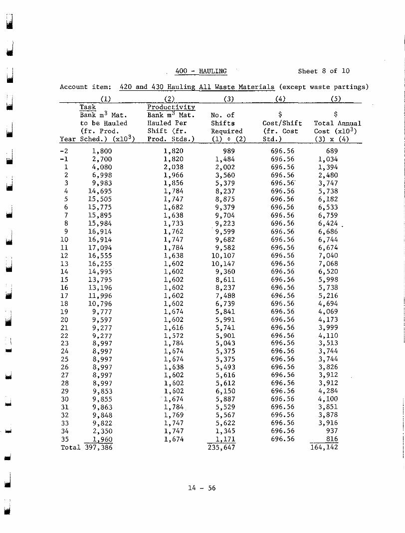
d . ~ .
i
d
ri
d
i 3
m
3
400 - HAULING Sheet 8 of 10
Account item: 420 and 430 Hauling All Waste Materials (except waste partings)
(1) (2) (3) (4) (5) __ Task Bank m3 Mat.
P r o d u c l F Bank m; Mat. No. of $ $
t o be Hauled Hauled Per Shifts Cost/Shift Total Annual (fr. Prod. Shift (fr. Required (fr. Cost Cost ~ 0 3 )
Year Sched.) (x103) Prod. Stds.) (1) f (2) Std.) (3) x (4) -2 -1 1 2
4 3
5 6 7 8
10 9
11 12 13 14 15 16 17 18 19 20 21 22 23 24 25 26 27 28 29 30 31 32 33 34
1,800 2,700 4,080 6,998
14,695 9,983
15,505 15,775 15,895 15,984 16,914 16,914 17,094 16,555 16,255 14,995 13,795
11,996 13,196
10,796 9,777 9,597 9,277 9,277 8,997 8,997 8,997 8,997 8,997 8,997 9,853 9,855 9,863 9,848 9.822
1,1320 1,820 2,038 1,966 1,856 1, :784 1,747 1,682 1,638 1,733 1,762 1,747 1, '784 1,638 1,602 1,602 1,602
1,602 1,602
1,602 1,674 1,602 1,616 1,.572 1,784 1,674 1,674
1,602 1,638
1,602 1,602 1,674 1,784 1,769 1.747
2; 350 1; 747 . .
35 1,960 Total 397,386
1,674
989 1,484 2,002 3,560 5,379
8,875 8,237
9,379 9,704 9,223 9,599 9,682
10,107 9,582
10,147 9,360 8,611 8,237
6,739 7,488
5,841 5,991 5,741 5,901 5,043 5,375 5,375 5,493 5,616 5,612
5,887 6,150
5,529 5,567 5,622 1,345
235,647 1,171
696.56 696.56 696.56
696.56 696.56
696.56 696.56
696.56 696.56 696.56 696.56 696.56 696.56 696.56 696.56 696.56 696.56 696.56 696.56 696.56 696.56 696.56 696.56 696.56 696.56 696.56 696.56 696.56 696.56 696.56 696.56 696.56 696.56 696.56 696.56 696.56 696.56
689
1,394 1,034
2,480 3,747 5,738 6,182 6,533 6,759 6,424 . 6,686 6,744 6,674 7,040 7,068 6,520 5,998
5,216 5,738
4,694 4,069 4,173 3,999 4,110 3,513 3,744 3,744 3,826 3,912 3,912 4,284 4,100 3,851 3,878 3,916 937 816
1.64,142 -
14 - 56
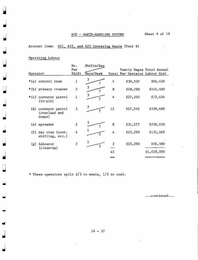
600 - WASTE-HANDLING SYSTEM Sheet: 9 of 10
Account item: 6 2 1 , 6 2 2 , and 623 Conveying Waste (Year 8 )
Operating Labour
No. 7 Per ' . S h i f t 'Days/Week Total Per Operator Labour Cost Operator
Yearly Wages Tota.1 Annual
* (a ) con t ro l room
*(b) primary crusher
*(c) conveyor patrol ( i n -p i t )
(d) conveyor patrol (overland and dumps)
(e) spreader
( f ) day crew (conv. s h i f t i n g , e t c . )
(9) labourer (clean-up)
4 $30,532 $81,420
- 8 $28 ,230 $141,400
1 - 4 $27,540 $72,454
3 * 1 2 $27,540 $330,480
$31,275 $250,220
4 2 4 $25,290 $101,160
2 $25 ,290 $50 ,580 - -~ 42 $1,028,000 - " - "
* These ope ra to r s sp l i t 2 / 3 t:o waste, 1 / 3 t o coa l .
. . . cfmt inued . . .
14 - 57
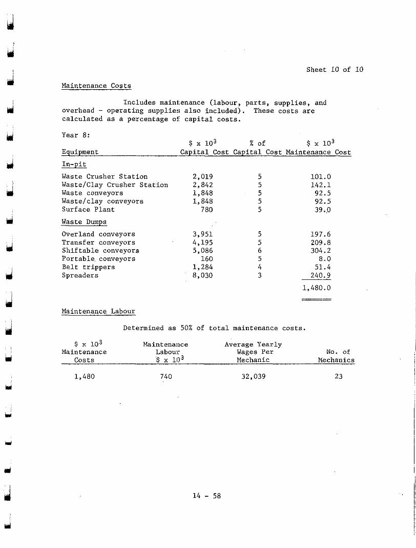
Sheet 10 of 10
Maintenance Costs
Includes maintenance (labour, parts, supplies, and overhead - operating supplies also included). These costs are calculated as a percentage of capital costs.
Year 8:
Equipment Capital Cost Capital Cost Maintenance Cost In-pit Waste Crusher Station 2,019 5 101.0 WasteIClay Crusher Station 2,842 5 142.1 Waste conveyors 1,848 5 92.5 Wastelclay conveyors 1,848 5 Surface Plant
92.5 780 5 39.p
$ x 103 % of $ x 103
Waste Dumps Overland conveyors Transfer conveyors
Portable conveyors Shiftable conveyors
Belt trippers Spreaders
3,951 5 4,195 5,086 6 160 5
1,284 4 8,030 3
197.6 5 209.8
304.2 8.0 51.4 240.9
1,480.0 "
" "
Maintenance Labour
Determined as 50% of total maintenance costs.
Maintenance Average Yearly Labour Wages Per
$ x 103
costs '$ x 103 Maintenance
Mechanic NO. of
Mechanics
1,480 740 32,039 23
Y
14 - 58
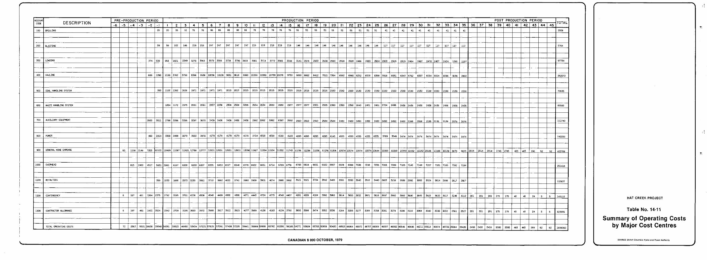
d
i
d
(j
14.5
14.5.1
FINANCIAL ANALYSIS
Approach
assoc ia ted wi th the min ing of Hat Creek coal were compiled. I n a d d i t i o n to t he cos t s desc r ibed i n t he p rev ious s ec t ions , cos t s were a l l o c a t e d t o the min ing p ro j ec t fo r t he o f f - s i t e f ac i l i t i e s (Hat Creek Diversion, cons t ruc t ion camp, and d iscre t ionary expenses) , l and , and ongoing s tud ie s a s soc ia t ed w i th t he p ro j ec t . These c o s t s are shown i n T a b l e
Befo re ca r ry ing ou t t he f i nanc ia l . ana lys i s a l l c o s t s
14-12.
The ob jec t ive of t h i s a n a l y s i s i s to de t e rmine t he p r i ce i n 1979 d o l l a r s of Hat Creek coa l de l ivered to the powerplan t . At t h i s pr ice the min ing venture must: y i e l d a r a t e of r e t u r n e q u a l t o B.C. Hydro 's cost of capi ta l . The p r i c e of Hat Creek coa l de l ivered 'to t h e powerplant could then be compared w i t h a n y a l t e r n a t i v e f u e l w i t h a n equivalent energy content.
14.5.2 Parameters
d ' i, n
U
fol lows :
(1) The b a s e d a t e f o r economic c a l c u l a t i o n s is October 1979 and t h e
The f inancial parameters used i n t h i s a n a l y s i s a r e a s
c a p i t a l and operating cash flows are in 1979 dol la rs ;
( 2 ) I n f l a t i o n r a t e s
The fo l lowing i n f l a t ion rates were appl ied to the cash f lows:
F i s c a l Year Rate %
1979-1980 8.50
1980-1981 7.75
1981-1982 7.50
1982-1983 7.25
Y
el 14 - 60
J
!d
F i s c a l Year Rate %
1983-1984 7.00
a f t e r 1984-1985 6.00
P lan t ope ra t ing da t e
It is assumed t h a t t h e f i r s t u n i t commences o p e r a t i o n i n t h e f i s c a l year 1989-1990;
Debt :Equi ty ra t io
The f i n a n c i a l s t r u c t u r e is 100% debt;
Rate of r e t u r n
A r a t e of r e t u r n of 9% is requ l r ed t o cove r i n t e re s t on ly . No o p e r a t i n g p r o f i t assumed;
Income t a x
No income t a x i s paid by B.C. Hydro;
P rov inc ia l roya l ty
I n t h e f i n a n c i a l a n a l y s i s , t h e r o y a l t i e s were c a l c u l a t e d a s 3.5% of t h e t o t a l c a p i t a l and opera t ing cos ts for the p ro jec t ;
Corporate overhead
Corporate overhead has been calculated a t 9% of t h e t o t a l c a p i t a l cos t i ncu r red ;
Construct ion Insurance a.nd Bonds
Construction insurance and bonds were ca l cu la t ed a t 0.5% of t h e t o t a l c a p i t a l c o s t s p l u s 0.044% of t h e t o t a l o p e r a t i n g costs. These costs were added t o t h e t o t a l c o s t s of t he p ro j ec t .
14.5.3 Analysis
The present vi ).lues o 'f the cash outf lows an d inflows a s soc ia t ed w i th t he p ro j ec t were equated. The cash outflows are t h e
14 - 61
'!
csi
d
annua l cap i t a l and opera t ing cash requi rements assoc ia ted wi th the mining operations and the cash inflows are determined from the schedule of coa l to be suppl ied to the powerplan t and the p r ice of t he de l ive red coa l .
above, a discount rate of 9% and a time horizon of 54 yea r s s ince expen- Th i s ana lys i s i nco rpora t ed t he i n f l a t ion rates s t i p u l a t e d
d i t u r e s a r e i n c u r r e d n i n e . y e a r s p r i o r t o t h e start of production:, and r ec l ama t ion ac t iv i t i e s con t inue fo r a 10-year period after mining ceases .
14.5.4 Conclusion
Creek coal del ivered to the powerplant is $0.60/GJ i n 1979 d o l l a r s , which i s equiva len t to $8.27 per tonne of coal with an average heat ing va lue of 18 MJ/kg, d ry bas i s . I f t he cos t of power for the mining ope ra t ions . i s exc luded t he p r i ce of c o a l is reduced to $0.57/GJ ($7.80 per tonne of coa l ) .
Based on t h e a.bove f inanc ia l pa rame te r s , t he p r i ce of Hat
d 1 4 - 62
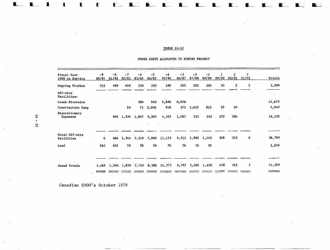
TABLE 14-12
OTHER COSTS AJ.WCATED TO MINING PROJECT
Fiscal Year -9 -8 -7 -6 -5 1989 in Service 80181 81/82 82/83 83/84 84/85 85/86 86/87 87/88 88/89 89/90 90/91 91/92
-4 -3 -2 -1 1 2 3 Totals
Ongoing Studies 555 490 445. 330 330 180 205 205 205 50 2 2 2,999
Off-site Facilities: Creek Diversion 380 540 5,680 8,070 14,670 Construction Camp 10 72 2,056 918 375 1,652 812 35 10 5,940
"""" ~ " - -
Discretionary Expenses 666 1,334 1,867 5,392 4,525 1,067 333 333 333 300 16,150
- Total Off-site Facilities 0 666 1,344 2,319 7,988 11,123 9,512 1,985 1,145 368 '310 0 36,760
Land 910 410 70 70 70 70 70 70 70 1,810
""""""
""__"" --- - Grand Totals 1,465 1,566 1,859 2,719 8,388 11,373 9,787 2,260 1,420 418 312 2 41,569 """ ~ ~ " - ~ - ""__ __ """ -
Canadian $ 0 0 0 ' ~ October 1979
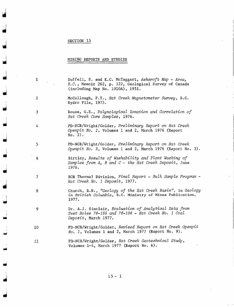
SECTION 15
MINING REPORTS AND STUDIES
a 1
d 2
4 3
d 4
Id 5
ri 6
d 7
. . !
mi 9
pi
i
10
11
Duffell, S . and K.C. McTaggart, Asheroft Map - Area, B.C. , Memoir 262, p. 122, Geological Survey of Canada (including Map No. 1010A), 1951.
McCullough, P.T., Hat Creek Magnetometer Survey, B.C. Hydro File, 1975.
Hat Creek Core Samples, 1976. Rouse, G.E., PalynologieaZ Zonation and Correlation of
PD-NCB/Wright/Golder, Preliminary Report on Hat Creek Gpenpit No. I , Volumes 1 and 2, March 1976 (Report No. 2).
PD-NCB/Wright/Golder, Preliminary Report on Hat Creek Gpenpit No. 2, Volumes 1 and 2, March 1976 (Reporc No. 3 ) .
Birtley, Results of washability and Plant Washing of Samples from A, B and C - the Hat Creek Deposit, June 1976.
BCH Thermal Division, Final Report - Bulk Sample Program - Hat Creek No. 1 Deposit, 1977.
Church, B.N., "Geology of the Hat Creek Basin", in Geology in British Columbia, B . C . Ministry of Mines Publication, 1977.
Dr. A . J . Sinclair, Evaluation of Analytical Data from Test Holes 76-135 and 76-136 - Hat Creek No. 1 Coal Deposit, March 1977.
PD-NCB/Wright/Golder, Revised Report on Hat Creek Gpenpit No. I , Volumes 1 and 2, March 1977 (Report No. 9).
PD-NCB/Wright/Golder, Hat Creek Geoteehnical S tudy , Volumes 1 - 4 , M:arch 1977 (Report No. 6).
1 5 - 1
i
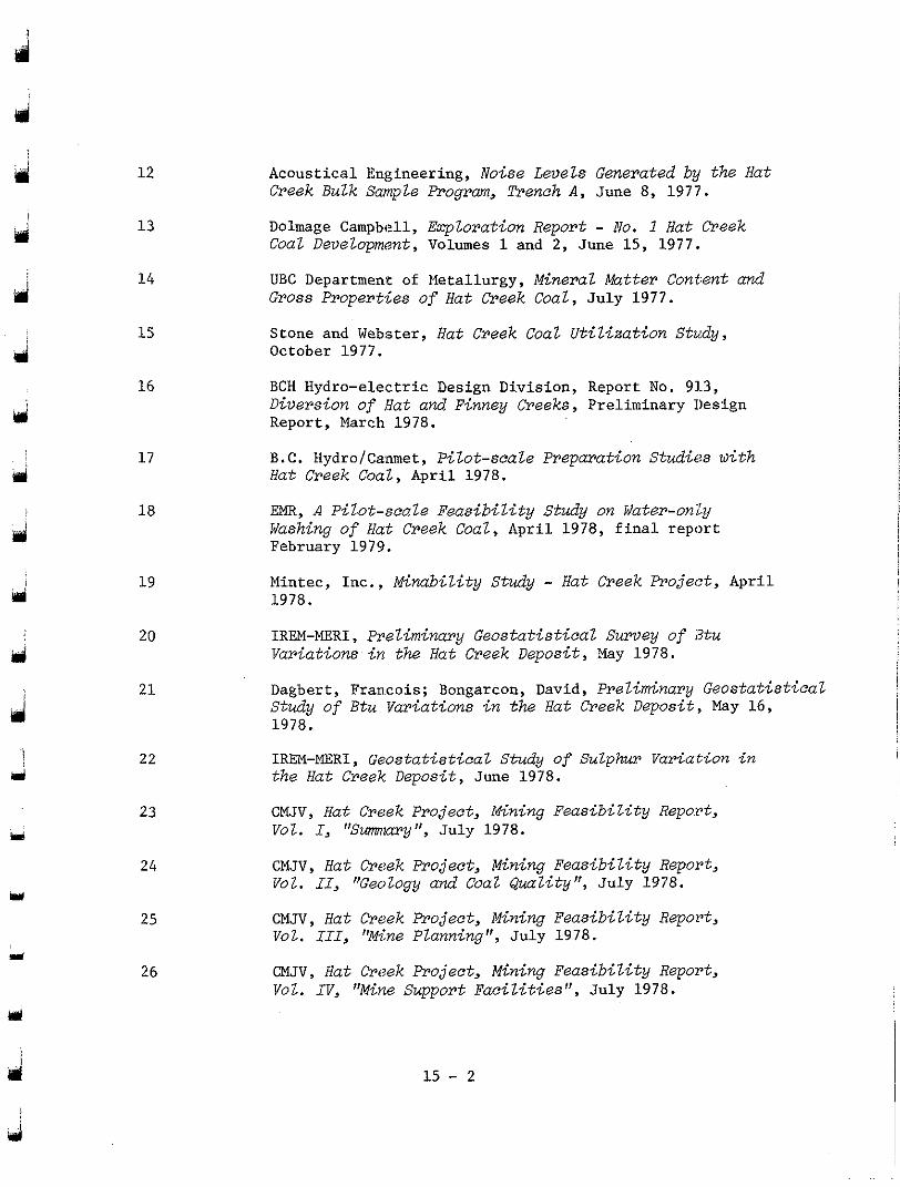
ri
12
13
14
15
16
17
18
19
20
2 1
22
23 ri
Acoustical Engineering, Noise Levels Generated by the Hat Creek Bulk Sample Program, Trench A , June 8, 1977.
Dolmage Campbell, Eqlorat ion Report - No. 1 Hat Creek Coat Development, Volumes 1 and 2, June 15, 1977.
UBC Department of Metallurgy, Mineral Mutter Cont:ent and Gross Properties of Hat Creek Coal, J u l y 1977.
Stone and Webster, Hat Creek Coal Utilization Study, October 1977.
BCH Hydro-electric Design Division, Report No. 91.3, Diversion of Hat and Finney Creeks, Preliminary Design Report, March 1978.
Hut Creek Coal, Apr i l 1978. B.C. HydrofCanmet, Pilot-scale Preparation Studies with
EMR, A Pilot-scale Feasibility Study on Water-only Washing of Hat Creek Coal, Apr i l 1978 , f i na l r epor t February 1979.
Mintec, Inc. , Minability Study - Hat Creek Project, Apri l 1978.
IREM"ERI , Preliminary Geostatistical Survey of i3tu Variations i n the Hut Creek Deposit, May 1978.
Dagbert, Fran.cois; Bongarcon, David, Preliminary Geostatistical Study of Btu Variations in the Hat Creek Deposit, May 16, 1978.
IREM-MERI, Geostatisticaz S tudy of Su~phur Variation in the Hut Creek Deposit, June 1978.
CMJV, Hut Creek Project, Mining FeasibiZity Repo:rt, Vol. I , "Smlary", J u l y 1978.
24 CMJV, Hat Creek Project, Mining Feasibility Repo.rt, Vol. 11, "GenZogy and CoaZ Q u a l i t y N , J u l y 1978.
25 CMJV, Hut Creek Project, Mining Feasibility Report, Vol. I I I , "Mine Planning", J u l y 1978.
26 CMJV, Hat Creek Project, Mining Feasibility Report, Vol . I V , "Mine Support Faci l i t ies" , Ju ly 1978.
i
ui 1 5 - 2
j I
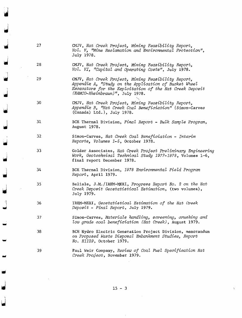
d
d
ui
U
27
28
29
30
31
32
33
34
35
36
37
38
Y
39 i
CMJV, Hat Creek Project, Mining Feasibility Report,
J u l y 1978. Vol. V, "Mine Reelmnation and Environmental Proteotion",
CMJV, Hat Creek Project, Mining Feasibil i ty Report, Vol. V I , "Capi.taz and Operating Costs", J u l y 1978.
Appendix A, "Study on the Application of Bucket WheeZ CMJV, Hat Creek Project, Mining Feasibil i ty Report,
Excavators for the Exploitation of the Hat Creek Deposit (NAMCO-Rheinbraun)", J u l y 1978.
CMJV, Hat Creek Project, Mining Feasibil i ty Report, \
Append& B, V a t Creek C o a l Beneficiation" {Simon-Carves (Canada) Ltd.:t, July 1978.
August 1978. BCH Thermal Division, F i n a l Report - Bulk Sample Program,
Simon-Carves, Hat Creek Coal Beneficiation - Interim Reports, Volwnes 1-5, October 1978.
Golder Associates, Hat Creek Project Preliminary Engineering Work, Geotechdcal Technical Study 1977-1978, Vohmes 1-6, f i n a l r e p o r t 'December 1978.
BCH Thermal Division, 1978 Environmental Field Program Report, A p r i l 1979.
Belisle, J.M./IREM-MERI, Progress Report No. 2 071 the Hat Creek Deposit Geostatistical Estimation, (two volumes), July 1979.
Deposit - Final Report , J u l y 1979. IREM-MERI, Geostatistical Estimation of the Hat Creek
Simon-Carves, Materials hadling, screening, crushing and low grade coal beneficiation (Hat Creek), August 1979.
BCH Hydro Electric Genera t ion Pro jec t Div is ion , memorandum on Proposed Haste Disposal Embankment Studies, R>?port No. H1129, 0c:tober 1979.
Paul Weir Company, Review of Coal Fuel Specification Hat Creek Froject, November 1979.
3
d 15 - 3
d 1
d
Y i
40
41
42
4 3
i
BCH, Geostatirsticaz Study of Sulphur Variations ' i n t he Hat Creek Deposit, 1979.
CMJV, Mine Drainage, 1979.
CMJV, Fugitive Mine-dust Study, 1979.
Subdivision, [gat Creek No. 1 Deposit, October 1979. BCH, Depositional Enviroment and Stratigraphic
15 - 4
d
Related Documents