4 Rate Control in Video Coding Zongze Wu 1 , Shengli Xie 1,2 , Kexin Zhang 1 and Rong Wu 1 1 School of Electronic and Information Engineering, South China University of Technology NO.381 Wushan Road, Tianhe Area, Guangzhou, 2 Faculty of Automation, Guangdong University of Technology, NO.100 Waihuanxi Road, Guangzhou university City, Panyu Area Guangzhou, China 1. Introduction Rate control plays an important role in video coding, although it’s not a normative tool for any video coding standard. In video communications, rate control must ensure the coded bitstream can be transmitted successfully and make full use of the limited bandwidth. As a consequence, a proper rate control scheme is usually recommended by a standard during the development, e.g. TM5 for MPEG-2, TMN8 and TMN12 for H.263, and VM8 for MPEG- 4, etc. H.264/AVC is the newest international video coding standard, and some work on rate control has been done for H.264/AVC too. In the contribution, a rate control scheme based on VM8 is adopted by H.264/AVC test model. In another contribution, an improved rate control scheme for H.264/AVC is provided with rate distortion optimization (RDO) and hypothetical reference decoder (HRD) jointly considered, part of which has also been adopted by H.264/AVC test model. 1.1 Function of rate control Rate control is that the encoder estimates the video bitrate based on the network available bandwidth, ensures the coded bitstream can be transmitted successfully and makes full use of the limited bandwidth. In other words, it is adjusting video output bits according to the channel is fixed or variable transmission rate. Now the core part of many video coding standards is the motion compensation and the DCT transform coding based on block. The number of the encoder output bits of each frame is changing with the active input image. Therefore, the bitstream has the inherent characteristics of changing. If the coding parameters remain unchanged in the compression process, the bits of the consumption of different frame will be significantly different. Due to the actual network bandwidth and storage medium, if we have nothing to do with the bitstream, the video communication system is likely to go abnormally. Generally, using a buffer makes the output bitstream smooth. The buffer capacity has certain limitation (If buffer is too big, the propagation delay of real-time communication is longer which is difficult to be accepted). In order to prevent buffer “overflow” and “underflow”, rate control must be used in encoder. www.intechopen.com

Welcome message from author
This document is posted to help you gain knowledge. Please leave a comment to let me know what you think about it! Share it to your friends and learn new things together.
Transcript

4
Rate Control in Video Coding
Zongze Wu1, Shengli Xie1,2, Kexin Zhang1 and Rong Wu1 1School of Electronic and Information Engineering,
South China University of Technology NO.381 Wushan Road, Tianhe Area, Guangzhou,
2Faculty of Automation, Guangdong University of Technology, NO.100 Waihuanxi Road, Guangzhou university City, Panyu Area Guangzhou,
China
1. Introduction
Rate control plays an important role in video coding, although it’s not a normative tool for
any video coding standard. In video communications, rate control must ensure the coded
bitstream can be transmitted successfully and make full use of the limited bandwidth. As a
consequence, a proper rate control scheme is usually recommended by a standard during
the development, e.g. TM5 for MPEG-2, TMN8 and TMN12 for H.263, and VM8 for MPEG-
4, etc. H.264/AVC is the newest international video coding standard, and some work on
rate control has been done for H.264/AVC too. In the contribution, a rate control scheme
based on VM8 is adopted by H.264/AVC test model. In another contribution, an improved
rate control scheme for H.264/AVC is provided with rate distortion optimization (RDO) and
hypothetical reference decoder (HRD) jointly considered, part of which has also been
adopted by H.264/AVC test model.
1.1 Function of rate control
Rate control is that the encoder estimates the video bitrate based on the network available
bandwidth, ensures the coded bitstream can be transmitted successfully and makes full use
of the limited bandwidth. In other words, it is adjusting video output bits according to the
channel is fixed or variable transmission rate.
Now the core part of many video coding standards is the motion compensation and the
DCT transform coding based on block. The number of the encoder output bits of each frame
is changing with the active input image. Therefore, the bitstream has the inherent
characteristics of changing. If the coding parameters remain unchanged in the compression
process, the bits of the consumption of different frame will be significantly different. Due to
the actual network bandwidth and storage medium, if we have nothing to do with the
bitstream, the video communication system is likely to go abnormally. Generally, using a
buffer makes the output bitstream smooth. The buffer capacity has certain limitation (If
buffer is too big, the propagation delay of real-time communication is longer which is
difficult to be accepted). In order to prevent buffer “overflow” and “underflow”, rate control
must be used in encoder.
www.intechopen.com

Recent Advances in Video Coding 80
1.2 History of rate control
In recent years, rate control has been the research focus in the field of video coding, many scholars and experts have achieved a lot of research achievements in the video rate control. The rate control in the video coding was proposed in 1992. The core of TM5 rate control algorithm is, under the situation that buffer is not overflow or overflow, distributing bits and determining the reference value of quantitative parameter by estimating the global complexity of the encoding frame, and adjusting the quantitative parameter by the activity of each block. In 1997, Chen (Chem., Hang.H.M., 1997) proposed a rate control algorithm which adjusting the frame rate adaptively is by the comprehensive consideration of the image contents and buffer state. This algorithm predicts the bitrate and quality of the image by source video model which is deduced according to the rate-distortion theory and used to describe the relationship of the bitrate, distortion and quantization step, and thus decides the number of skip frames. TMN8 infers the predicted formula of the target bitrate according to the experience of entropy model, then refers to the rate-distortion model, then computes the optimum quantization step under the MSE rule by Lagrange optimization. VM8 is based on quadratic R-Q model, and uses the model in different types of image frames to achieve rate control, meanwhile introduces sliding window to adjust the parameters of the model in order to realized multi-scale, different complexity rate control. In 2001, he (Zhihai He, 2001) proposed a ρ domain code rate control algorithm; it establishes the one-to-one correspondents between output rate and the quantification step by the linear relationship of the percentage of the quantified DCT coefficients and the output rate. This algorithm has achieved good results in the standard of JPEG, H.263, MPEG-4 and so on. The latest video coding H.264 standard in the code control is proposed by Li Zhengguo etc in 2003.The problem with the JM H.264 encoder lies with the fact that the residual signal depends on the choice of coding mode and the choice of coding mode depends on the choice of QP which in turn depends on the residual signal (a chicken and egg type of problem). The adopted solution in the JM encoder is one where the choice of QP is made prior to the coding mode decision using a linear model for predicting the activity of the residual signal of the current basic unit (e.g. frame, slice, macroblock) based on the activity of the residual signal of past (co-located) basic units. Once the residual signal activity is predicted, the same rate model used in VM8 is employed to find a QP which will lead to a bit stream that adheres to the specific bit budget allocation and the buffer restrictions. In order to get a better effect on rate control, we usually make some melioration based on the joint scalable video model (JSVM). The JSVM provides a rate control scheme, and the JSVM software is the reference software for the Scalable Video Coding (SVC) project of the Joint Video Team (JVT) of the ISO/IEC Moving Pictures Experts Group (MPEG) and the ITU-T Video Coding Experts Group (VCEG). The JSVM Software is still under development and changes frequently.
1.3 The key technique in rate control
Because of transmission bandwidth and storage space limitation, video applications for higher compression ratio, nondestructive coding can provide the compression ratio but cannot satisfy the demand of actual video applications, but if we can accept some degree of distortion, high compression ratio is easy to get. Human visual system for high frequency signals change not sensitive information loss, high frequency part does not reduce subjective visual quality. Video coding algorithm of mainstream DCT quantization method is adopted
www.intechopen.com

Rate Control in Video Coding 81
to eliminate video signals, the visual physiology redundant than lossless higher compression ratio and will not bring the video quality decrease significantly. When using a lossy coding method, it is related to the difference between the reconstruction
images g (x, y) and the original image f (x, y). Generally, the distortion factor D function can
form according to need, such as selecting any cost function, absolute square cost function,
etc. In the image coding D is computed as: D 噺 E岶岷f岫x, y岻 伐 g岫x, y岻峅態岼 1.3.1 Rate distortion model
Beneath the image compression, there is a problem: under the premise of certain bitrate,
how to make the distortion of the reconstructed image coding minimum. Essentially, it is the
problem of the relationship between encoding rate and the distortion. The rate-distortion
theory is to describe the relations of the distortion of coding and encoding speed. Although
the rate-distortion theory is not optimal encoder, but it gives the lower compression allows
under the condition of the certain information distortion allows. Practical application of
many rate-distortion models is built on the basis of experience. For example, in TM5, a
simple linear rate-distortion model is introduced. In TMN8 and VM8, a more accurate
quadratic R-D model is used, which can reduce rate control error and provide better
performance but have relatively higher computational complexity. In a different way, the
relation between rate and QP is indirectly represented with the relation between rate and ρ,
where ρ is the percent of zero coefficients after quantization; and also, a modified linear R-D
model with an offset indication overhead bits is used for rate control on H.261/3/4 in the
contributions. Here are some of the common empirical models:
1. A simple linear rate-distortion model
R岫QP岻 噺 C濯沢 抜 SQP
Where R(QP) is the bits to encode when then quantization step is QP, S is the encoding
complexity. C濯沢is the coefficient of the model.
2. Second rate distortion model
Model hypothesizes information source obey Laplace distribution, namely: p岫x岻 噺 ゎに e貸池|淡|
Where x is the value of the information source, and ゎis a coefficient.
The distortion defined with absolute deviation as: D岫x, x博岻 噺 |x 伐 x|拍 .
So we can get the rate-distortion function:
R岫D岻 噺 log なゎD
The Taylor expansion of R(D) is
www.intechopen.com

Recent Advances in Video Coding 82
R岫D岻 噺 磐 なゎD 伐 な卑 伐 なに 磐 なゎD 伐 な卑態 髪 R戴岫D岻 噺 伐ぬに 髪 にゎD貸怠 髪 なにゎ態 D貸態 髪 R戴岫D岻 Then we get the R-D model: R辿 噺 ゎ怠Q辿貸怠 髪 ゎ態Q辿貸態
Where ゎ怠 and ゎ態 are two coefficients. In order to enhance the accuracy of the R-D model, bring in two parameters MAD and Rh, then:
R岫Q岻 伐 R竪 噺 X怠 ∗ MADQ 髪 X態 ∗ MADQ態
Where MAD is the mean absolute difference between the original frame and reconstruction of frameR竪 is the number of bits of the header information and information such as the motion vector occupies; X怠and X態 are two coefficients.
3. domain linear model
He (Zhihai He,2001) found, the proportion of the coefficient after quantification of zero, increases in a monotonic way with the growth of Quantization step. So the original R - D relationship may be allude to R-ρrelationship. The research finds R-ρ meets the relationship as follow: R岫ρ岻 噺 θ岫な 伐 ρ岻 Whereθ is a constant.
4. Logarithmic model
Provided the source obeys Gaussian distribution which the mean is 0 and the variance is σ態, The distortion defined as :D岫x, x博岻 噺 |x 伐 x|拍 . While the rate-distortion function is:
R岫D岻 噺 崔 なに log δ態Dど,D 伴 δ態 , ど 判 D 判 δ態
Where R(D) is the average coding bits of every pixel. Supposed that distortion and the quantification coefficients is linear relationship, namely: D岫Q岻 噺 m 抜 Q
So get the R – Q model: R岫Q岻 噺 ゎ 髪 が log なQ
This model is much simpler, used by many documents. But because the image of the DCT coefficients do not accord with Gaussian distribution and D and Q usually is not linear relationship. Therefore, this adaption of the model is so-so.
1.3.2 Rate distortion optimization (RDO)
Rate control usually incorporate with rate distortion optimization (RDO), which could brings more coding efficiency for optimized mode decision and bit allocation. In order to
www.intechopen.com

Rate Control in Video Coding 83
reduce the temporal correlations among successive frames, inter-frame coding is widely used, which is usually realized by motion compensation prediction (MCP). With block basis motion estimation, the residual texture and motion vectors associated in the current block need to be coded finally. Obviously, for a given bit rate, over-large motion information or residual information wouldn’t give the best coding efficiency, so the trade-off between the motion information and the residual information, on which the motion compensated video coding heavily depends, should be considered. The trade-off is usually achieved by a rate distortion optimization (RDO) that is formulated by minimizing the cost J, shown as follows J 噺 D 髪 λ誰丹担R
Here the distortion D representing the residual (texture or prediction error) measured as
sum absolute distortion (SAD) or mean absolute distortion (MAD), is weighted against the
number of bits R associated with the motion information by using the Lagrange multiplier λ誰丹担. Each λ誰丹担 corresponds to a bit rate range and a trade-off between the motion
information and the residual information. A large λ誰丹担 works well at a low bit rate while a
small λ誰丹担works well at a high bit rate.
1.3.3 The influences of the coding parameters on the code rate control
Any control on encoding bitrate must consider the tradeoff of the quality and efficiency of compression. The bitrate reduce is at the cost of lower quality. In video encoder, we can control output bitrate by adjusting the following four coding parameters: 1. Frame rate, namely frames per second coding. By adjusting the frame rate, make the
encoder output rate achieve specified requirements. A control frame rate for video signal is temporal redundancy, rather than spatial redundancy. Usually the quality requirements in a single image are higher, so we cannot decrease rate by reducing the number of each frame coding bits.
2. The coding for some transform coefficients of each image block, for example, transform coefficient as diagonal coefficient (1,1), (2,2), or just to code pixel pieces of low-frequency coefficients. The DC coefficients have a large proportion in the pixel block energy, therefore, in order to maintain certain quality of image they must be encoded. However, AC coefficients can be discarded or encode a part of them to decrease the output bitrate. In the image with a few of details, spatial correlation, this method can get good quality image in low bit rate, but when the image with a lot of details, if we remove much AC coefficient, the image quality will greatly reduce.
3. Quantization parameter (QP). Quantitative parameter has considerable influence on the coding bits of the image block. When the video sequences have acuteness exercise, in order to obtain high temporal video quality, we can reduce spatial video quality to achieve the code rate control with details quantified roughly by increasing the value of each image QP. With the QP increasing, the value of the quantified DCT coefficients decrease, then the zero coefficient will be more, as a result, the output encoding bits become less. On the other hand, if the QP is smaller, the value of the quantified DCT coefficients increase, then the output encoding bits become more. In H.264, we can achieve different levels of the code rate control through the adjustment frame, the Basic Unit or the quantitative parameters.
4. The optimal QP value, through quantitative determination coefficient of smaller, after can be obtained in the run-length coding before the zero coding, quantity higher degree
www.intechopen.com

Recent Advances in Video Coding 84
after compression coding, output bits less. Instead, the small, DCT QP coefficients quantification, the value after the coding bits. In the h.264 encoder, through the adjustment frame, the Basic Unit (Basic Unit) or the quantitative parameters can achieve different levels of the code rate control.
5. Motion detection threshold. Motion detection threshold is used to determine the macroblock of the prediction frames (P) to code or skip. If the threshold improves, the sensitivity of the movement of the encoder reduces, then the number of coding macroblocks decrease, therefore, the bits of P frame needing to code decrease. However, it is at the cost of image motion video quality. On the other hand, if the threshold is lower, the movement sensitivity will improve, so there will be more macroblock needing to code, as a result, the bits will increase. While INTRA or INTER detection threshold is also available for controlling the output bitrate of P frame. More INTRA coded, more the output bits become, and higher the video quality is.
The process of adjusting the coding the four values of the parameters of the code, can effectively control the output video encoder to meet current rate control requirements. However, they also may cause changes in the image quality. At present, most of the code rate control schemes use quantitative parameters control mode to achieve rate control.
2. Rate control theory
The video communication system widely use MC-DPCM or DCT video coding algorithm, the stream has the inherent characteristics of variable bit rate. If encoding parameters remain the same during the compression, different number of bits between frames will consume significantly different. As the actual network bandwidth and storage media capacity constraints on the rate of this stream without any constraints on the impact of video communication system is catastrophic and cannot guarantee that the system work. Now main international video coding standards (i.e., MPEG-1, MPEG-2, MPEG-4, H.261, H.263 and H.264) video images use DCT to eliminate spatial correlation. Image data (image data to be the original frame and the predicted residual error between frames using the temporal prediction) is divided into blocks of such size, and then block by block implemented of the DCT and quantization. Less or does not contain details of the details of the block will have fewer non-zero coefficient, therefore the details of the block produced more non-zero coefficient is greater. Block of varying degrees of redundancy has led to different blocks of the same frame number of bits needed to encode a big difference. If only intra-frame coding is taken into account, the number of bits consumed by each frame as the scene complexity will vary. Complex scene is much larger than the number of bits needed to simple scenes. In the same scene, the rate changes are usually small. Figure 2.1 (a) shows the varying bit rate of MPEG-2 using intra-prediction coding in which all coding parameters are unchanged. From the figure we can see: in the same scene, the rate has changed little; when the scene change or changes, the rate changes dramatically. Motion estimation is another cause to the bit rate fluctuations of compressed bit stream. When using temporal motion estimation, the encoded data includes motion vectors and residual coefficients. Motion estimation in MC-DPCM / DCT coding is based on the basis of translational motion model. If the scene contains only small movements or simple linear sports (such as moving the camera lens), block-based motion estimation can be effective to predict the movement. In this case, the motion vector has relatively high share of the number of bits. If the scene contains fast or complex motion (such as rotation, scaling or
www.intechopen.com

Rate Control in Video Coding 85
random movement, etc.), the block-based motion estimation is difficult to predict the actual movement, especially in the scene change or changes, many of the macro block coding frame will be used intra encoding mode, allows a significant residual coding bits by force mouth.
(a) Stefan/MPEG-2 (b) Coatguard/H.263
Fig. 2.1
Figure 2.1 (b) shows the H.263 stream in the frame bits curve. Each frame is the frame from
its precursor predicted residual frame using the DCT transform compression. Because there
is no prediction reference frame to the first frame, all macro blocks in the first frame are
coded in intra mode and therefore consume more bits; the rate of the following frames don’t
change much, because they are highly related which means containing the same detail and
movement. But in the 30-th frame or so, there is a peak value, because the camera lens is
dragged here and therefore reduces the efficiency of motion estimation; as a result, most of
the macro blocks in these several frames were intra coded, resulting in a rate increase. In the
subsequent long period of time, no scene change occurs, rate changes are small.
In video coding, the coding type of frame is another factor that affects the bit rate. I frame
uses only intra prediction, so the compression ratio is usually very low. P frame uses inter-
frame prediction, and its compression efficiency is usually higher than I frame. B frames can
effectively deal with the new target occlusion and scene access issues because of the use of
the bi-directional prediction: compared to P frame, the mean of B frame using the two
images to compensate obtains higher signal to noise ratio. However, B frames will not be
used for prediction and allowing the use of fewer bits encoding the number of coding which
will not cause distortion proliferation. In A group of pictures (GOP) of the MPEG-1 and
MPEG-2, different types of frame encoding result in a significant difference between the
numbers of bit.
Before transmission, all rate fluctuations (including intra-frame, inter-frame and within a
GOP) must be effectively controlled, since the actual network bandwidth and storage media
capacity is limited. Many of the existing network and storage media are operating in
constant bit rate (CBR). Even if they work at a variable bit rate (VBR) model, the maximum
stream rate fluctuations will also have the corresponding constraints. So the coded video
sequence must be adjusted to meet the network bandwidth and storage media capacity
requirements. In addition, the non-binding rate is not conducive to the management of
channel bandwidth.
www.intechopen.com

Recent Advances in Video Coding 86
Rate control is a necessary part of an encoder, and has been widely applied in standards
including MPEG-2, MPEG-4, H.263, and so on. Rate control belongs to the budget-
constrained bit allocation problem whose goal is to determine how many bits to use on
different parts of the video sequence and to do so in such a way as to maximize the quality
delivered to the end user. A natural way to approach these problems is to consider the R-D
trade-offs in the allocation. Therefore, a practical video encoder employs rate control as a
way to regulate varying bit rate characteristics of the coded bit stream in order to produce
high quality decoded frame at a given target bit rate. In this process, there are two key
phrases: 1) to find out a reasonable and accurate R-D model to describe the characteristic of
a specific signal source; 2) to allocate every bit unit appropriately in order to minimize to
overall distortion.
Rate control in video coding is typical accomplished in three steps:
1. Update the target average bit rate in terms of bps for each short time interval, also
referred to as the rate update interval;
2. Determine the coding mode(e.g., I-, P-, or B-frame) and the target bit budget for each
frame to be coded in this interval, which is usually based on the target average rate for
the interval and the current buffer fullness;
3. Determine the coding mode and QP for each MB in a frame to meet the target rate for
this frame.
2.1 Bit allocation
We now present a series of generic allocation problem formulations that spell out some of
the possible constrains, the encoder will have to meet when performing this parameter
selection. It would be trivial to achieve minimal distortion if no constraints on the rate were
imposed. We will formulate two classes of closely related problems where the rate
constraints are driven by (i) total bit budget (e.g., for storage applications) and (ii)
transmission delay (e.g., for video transmission).
Storage constraints: Budget-constrained allocation
In this class of problems, the rate is constrained by some restriction on the maximum total
number of bits that can be used. This total number of budget 迎脹 has to be distributed among
the different coding units with the goal of minimizing some overall distortion metric. The
problem can be restated as follows:
Find the optimal quantizer, or operating point, x(i) for each coding unit i, such that
( )1
N
ix i Ti
r R
(1a)
and some metric 血岫穴怠掴岫怠岻, 穴態掴岫態岻, … , 穴朝掴岫朝岻岻 is minimized.
Several kinds of metric are mostly used in video coding, such as minimum average
distortion (MMSE), minimax approach (MMAX), and lexicographically optimal approach
(MLEX). Minimum average distortion
In a MMSE problem, we have that 血盤穴怠掴岫怠岻, 穴態掴岫態岻, … , 穴朝掴岫朝岻匪 噺 ∑ 穴沈掴岫沈岻朝沈退怠 .
www.intechopen.com

Rate Control in Video Coding 87
Minimax approach Alternatively, a MMAX approach would be such that 血盤穴怠掴岫怠岻, 穴態掴岫態岻, … , 穴朝掴岫朝岻匪 噺 兼欠捲沈退怠朝 穴沈掴岫沈岻. Lexicographically optimal approach
MLEX approaches have been extensions of the mini-max solution. The MLEX approach compares two solutions by sorting their distortions or their quantization indices. Allocations derived under the MLEX constraint have the interesting property of tending to equalize the distortion or the quantization scale across all coding units.
A more general version of the problem of budget-constrained allocation may arise in situations where there are not only limitations on total rate but also in the rate available for subset of coding units. Assume, for example, that a set of images has to be placed in a storage device that is physically partitioned and that it is impossible for undesirable for performance reasons to split images across one or more devices. In this case, we will have to deal with partial constraints on the set of images assigned to each particular devide, in addition to the overall budget constraint. An optimal allocation that considers only the aggregate storage constraint may result in an invalid distribution between the storage devices. Consider the case where two storage devices, each one of size迎脹/に, are used. We will have
the following constraint, in addition to the budget constraint of Eq.(1a): ∑ 堅沈掴岫沈岻朝迭沈退怠 判 迎脹/に,
Where 軽怠 is the number of coding units that are stored in the first storage device. 軽怠 itself
may not be given and may have to be determined.
Delay-constrained allocation
Solutions of storage-constrained allocation above cannot encompass situations where the coding units, for example, a series of video frames, are streamed across a link or a network to a receiver. In this situation, each coding unit is subject to a delay constraint; therefore, it has to be available at the decoder by a certain time in order to be played back.
For example, let a coding unit be coded at time t and assume that it will have to be available at the decoder at time t T , where T is the end-to-end delay of the system. This imposes a constraint on the rate, which has to be low enough that transmission can be guaranteed within the delay, can be used for each frame. If each coding unit lasts ut seconds, then the end-to-end delay can be expressed as / uN T t in coding units. The video encoder will have to ensure that the rate selection for each frame is such that no frames arrive too late at the encoder. Given the delay constraints for each coding unit, the problem can be restated as follows: Find the optimal set of quantizers x(i) such that (1) each coding unit i encoded at time it is received at the decoder before its “deadline” i it , and, (2) a given distortion metric, such as MMSE and MMAX, is minimized. Note that the problem doesn’t impose any constraint on the transmission bandwidth; however, in practical applications we must deal with limited bandwidth and expenditures which rise to meet the incomes.
The complexity of this allocation problem depends on the channel characteristics: we need to know if the channel provides a constant bit rate (CBR) or a variable bit rate (VBR), if the
www.intechopen.com

Recent Advances in Video Coding 88
channel delay is constant, if the channel is reliable, etc. For simplicity, in the followings we assume that i T for all i. In both CBR and VBR cases, data will be stored in buffers at encoder and decoder. Assume a variable channel rate of C(i) during the i-th coding unit interval. Then we will have that the encoder buffer state at time I is
( )( ) max( ( 1) ( ),0)ix iB i B i r C i ,
with B(0) = 0 being the initial state of the buffer. Consider the constraints need to be applied to the encoder buffer state. First, the buffer state B(i) cannot grow indefinitely because of the finite physical buffer. If maxB is the physical memory available then we need to guarantee that max( )B i B at all time. Secondly, in order to the delay constraint not to be violated, we need to guarantee that the data corresponding to coding unit i is transmitted before it T ; that is, transmission has to be completed during the next N coding unit intervals. Then, we can define the effective buffer size ( )effB i as
1
( ) ( )i N
effk i
B i C k
,
Then correct transmission is guaranteed if
( ) ( ),effB i B i i .
As an example, consider the case where ( ) /TC i C R N is constant. If the system operates with an end-to-end delay N the buffer can store no more than N C bits at time t. In general, the applicable constraint will be imposed by the smallest of ( )effB i and maxB . Assuming that sufficient physical buffer storage is available, the problem becomes:
Buffer-constrained allocation
Find the optimal set of quantizers ( )x i for each i such that the buffer occupancy
( )( ) max( ( 1) ( ),0)ix iB i B i r C i ,
is such that
( ) ( )effB i B i
and some metric 1 (1) 2 (2) ( )( , ,..., )x x Nx Nf d d d is minimized.
2.2 Rate distortion optimization
Rate distortion optimization theory, which is derived from information theory, is the theoretical basis for optimization of video coding. Also the rate distortion optimal coding techniques are widely used in every video coding system. First of all, the distortion rate distortion optimization is closely related with the quantization, thus the rate distortion optimization in the quantizer design plays an important role in the design of weighted quantization matrix and adjusting quantified deadzone interval, etc.; rate distortion optimization can also be used to select the macro-block encoding parameters, such as the choosing of the best motion vector and coding mode, etc.
www.intechopen.com
Rate Control in Video Coding 89
Another important application of rate distortion optimization techniques is to solve the
optimization problems of bit allocation, i.e., how to find the optimal solution of numbers of
bit distributed among different macro blocks and pictures in order to obtain the minimum
total distortion within the total bit budget constraint. And this issue is the goal of rate
control. Since the basic unit (macro-block or image) in bit allocation and the distortion is
related to each other, which makes the bit allocation problem become more complex. As a
result, we often utilize the monotonicity of R-D characteristic or assume independent cases
to reduce the complexity of solving the problem.
We first introduce the basic concepts of rate distortion theory, including the definition of
rate distortion function and the forms of R-D function about the source of Gaussian
distribution and Laplacian distribution. This is because natural images are usually assumed
to obey Gaussian distribution, while transformation coefficient is usually assumed to obey
the Laplacian distribution. R-D models are generally derived from the typical rate-distortion
function based on the foregoing assumptions.
Rate-distortion theory is an important part of information theory and is the theoretical basis
of data compression and quantization. "Rate" represents the measure of signal; “distortion”
reflects the difference between source signals in current rate and the source. The amount of
information is measure by entropy which is defined as:
logi iH p p
For two signals X, Y, the mutual information is defined as:
( ; ) ( ) ( | )I X Y H X H X Y
Rate distortion function reflects the entropy of mutual information between source signals
and received signals through the channel transmission or coding distortion. Assume that X
to be the source signals, Y to be the signal through channel transmission at the receiver, the
rate distortion function is defined as:
( | )( ) min ( ; ).
j jp y xR D I X Y
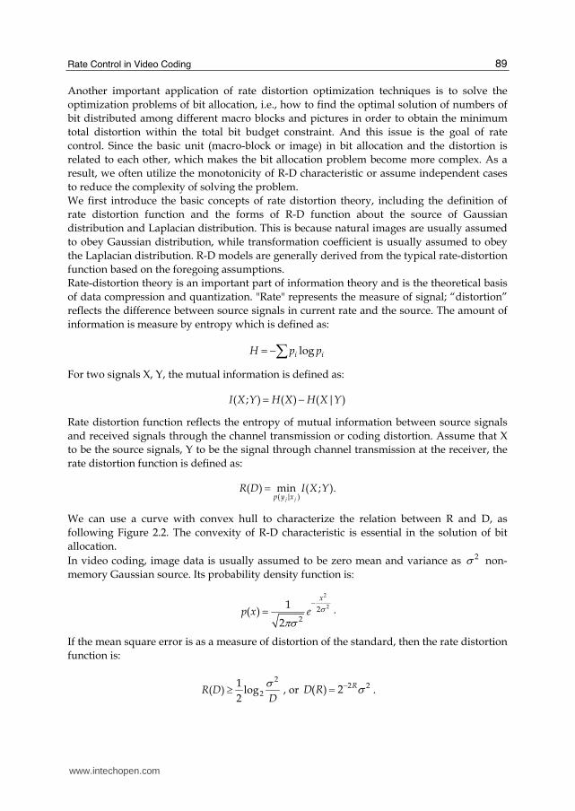
We can use a curve with convex hull to characterize the relation between R and D, as
following Figure 2.2. The convexity of R-D characteristic is essential in the solution of bit
allocation.
In video coding, image data is usually assumed to be zero mean and variance as 2 non-
memory Gaussian source. Its probability density function is:
2
22
2
1( )
2
x
p x e
.
If the mean square error is as a measure of distortion of the standard, then the rate distortion
function is:
2
2
1( ) log
2R D
D
, or 2 2( ) 2 RD R .
www.intechopen.com

Recent Advances in Video Coding 90
Fig. 2.2 The convexity of R-D characteristic is essential in the solution of bit allocation
In transform coding, DCT transform coefficients are usually simulated with Laplacian distribution. For the Laplacian distribution of rate-distortion function is usually expressed respectively as:
22
2(1 coth )
2
QQ Q
D e
,
2 2
2
2log(1 ) log( )
2sinh1 2
Q Q
Q
QR e e
Qe
,
where Q is the quantization step size. Note that when the quantization step Q increases,
distortion D is close to the source variance 22
2 .
Bit allocation optimization problem in video coding is given under the constraints of bit rate to find the optimal solution that obtains the best image quality. In order word, it is restated as follow:
min{ }D , with the constraint that maxR R Note that the bit allocation constraints can be either to the entire video sequence bit constrained, minimizing the cost of rate distortion of each image and the final optimal effect of encoded sequence, or to a single frame so that obtains the optimal coding of each macro block. Current methods commonly are used Lagrangian optimization, dynamic programming method and etc.
Lagrangian optimization
Consider the case where the rate R and distortion D can be measured independently for each coding unit; i.e., the R-D data for coding unit i can be computed without requiring that other coding units be encoded as well. One example of this scenario is the allocation of bits to different blocks in a DCT image coder where blocks are individually quantized and entropy coded.
Assume that the basic coding units (block or image) are mutually unrelated. Then the
distortion and rate are irrelative to the adapted quantization parameter. Suppose the k-th
www.intechopen.com

Rate Control in Video Coding 91
block adapts quantization parameter Qk, then we obtain the corresponding distortion and bit
rate of Dk and Rk, respectively. To solve the problem, we need to find an optimal set of Qk* such
that minimizing the total distortion within the constraint of total budget R:
1
* * * *1 2
( ,..., ) 1
( , ,..., ) arg min ( ),n
n
k n i iQ Q i
Q Q Q Q D Q
with the constraint that 1
( )n
i ii
R Q R
.
Lagrangian multiplier can be used to solve this problem. Firstly, we convert it to the optimization without constraints:
1
*
( ,..., ) 1 1
arg min ( ) ( ).n
n n
i i i iQ Q i i
Q D Q R Q
Since the distortions and rates in different units are mutually unrelated, we restate the former equation as:
* arg min[ ( ) ( )]k
k i i i iQ
Q D Q R Q
Note that for each coding unit i , the point on the R-D characteristic that minimizes
( ) ( )ix i ix id r is the point at which the line of absolute slope is tangent to the convex hull of the R-D characteristic. Since is the same for every coding unit on the sequence, we can refer to this algorithm as a “constant slope optimization”.
min
ii
x
i
J
D x
R x
Fig. 2.3
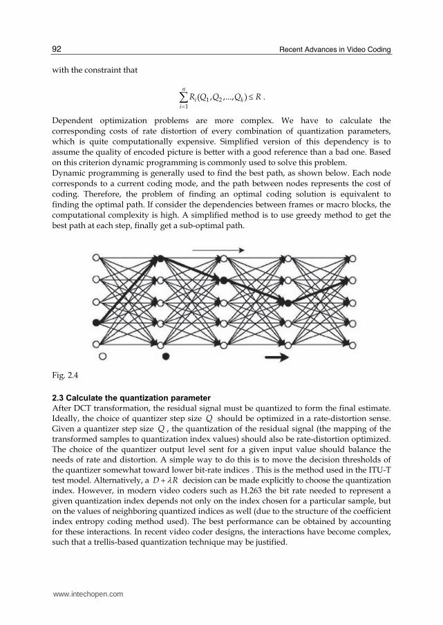
Dynamic programming
The foregoing Lagrangian optimization assumes that the basic units are mutually independent, so that minimizing the cost of rate-distortion in each unit results in the optimal solution. However, in the practical encoding process, each unit will have correlations with others because of the introduction of temporal and spatial prediction. As a result, their cost of rate distortion is mutually affected. Dependency exists in this rate-distortion problem can be stated as:
1
*1 2
( ,..., ) 1
arg min ( , ,..., ),n
n
i kQ Q i
Q D Q Q Q
www.intechopen.com
Recent Advances in Video Coding 92
with the constraint that
1 21
( , ,..., )n
i ki
R Q Q Q R
.
Dependent optimization problems are more complex. We have to calculate the
corresponding costs of rate distortion of every combination of quantization parameters,
which is quite computationally expensive. Simplified version of this dependency is to
assume the quality of encoded picture is better with a good reference than a bad one. Based
on this criterion dynamic programming is commonly used to solve this problem.
Dynamic programming is generally used to find the best path, as shown below. Each node
corresponds to a current coding mode, and the path between nodes represents the cost of
coding. Therefore, the problem of finding an optimal coding solution is equivalent to
finding the optimal path. If consider the dependencies between frames or macro blocks, the
computational complexity is high. A simplified method is to use greedy method to get the
best path at each step, finally get a sub-optimal path.
Fig. 2.4
2.3 Calculate the quantization parameter After DCT transformation, the residual signal must be quantized to form the final estimate.
Ideally, the choice of quantizer step size Q should be optimized in a rate-distortion sense. Given a quantizer step size Q , the quantization of the residual signal (the mapping of the transformed samples to quantization index values) should also be rate-distortion optimized. The choice of the quantizer output level sent for a given input value should balance the needs of rate and distortion. A simple way to do this is to move the decision thresholds of the quantizer somewhat toward lower bit-rate indices . This is the method used in the ITU-T test model. Alternatively, a D R decision can be made explicitly to choose the quantization index. However, in modern video coders such as H.263 the bit rate needed to represent a given quantization index depends not only on the index chosen for a particular sample, but on the values of neighboring quantized indices as well (due to the structure of the coefficient index entropy coding method used). The best performance can be obtained by accounting for these interactions. In recent video coder designs, the interactions have become complex, such that a trellis-based quantization technique may be justified.
www.intechopen.com

Rate Control in Video Coding 93
Transform coefficient bit allocations are optimized quantization of the wavelet coefficients, its purpose is to choose the appropriate quantized index for all transform coefficients, which makes coding coefficients and the number of bits used in coding distortion to achieve a desired balance between, that is the minimum cost. This is one of typical applications using the rate distortion optimization techniques. Quantization is to balance the amount of data encoded with the coding distortion. At the same time it is also closely related with the features of transformation (usually orthogonal transform). In the latest coding standard H.264 and AVS there is an emergence of new technologies in quantitative transform characteristics. They use integer transform instead of floating-point of the traditional DCT. This modification not only reduces the complexity of transform, but also avoids mismatch caused by floating point calculations. At the same time quantitative and transform normalized combination can be achieved only through multiplication and shift. However, the magnitude of each line in transformation matrix is not necessarily equal, which means to require for normalization in encoder and decoder. If the encoder and decoder implementation with parameter quantization table, more storage space is in need. In AVS, each line of transformation matrix is approximate in magnitude, so there only requires for normalization in encoder, and therefore the size of quantization table in decoder is decreased. As a result, the storage complexity in decoder is reduced. However, this transformation method brings new problems on rate-distortion analysis. Transform is one of the core technologies in video coding. Through transformation the spatial redundancy between image data can be effectively removed. As DCT transform has excellent property of energy concentration, it is widely applied to various types of coding standards, such as MPEG-2, MPEG-4, H.263, etc.
The algorithm for the rate-constrained mode decision can be modified in order to incorporate macro block quantization step-size changes. For that, the set of macro block modes to choose from can be extended by also including the prediction mode type INTER Q for each macro block, which permits changing Q by a small amount when sending an INTER macro block. More precisely, for each macro block a mode M can be chosen from the set
{ , , , 4 ,..., ( 4),
( 2), ( 2), ( 4)}
M INTRA SKIP INTER INTER V INTER Q
INTER Q INTER Q INTER Q
where, for example, ( 2)INTER Q stands for the INTER mode being coded with quantizer step size reduced by two relative to the previous macroblock. Hence, the macroblock Q selected by the minimization routine becomes dependent on MODE Otherwise the algorithm for running the rate-distortion optimized coder remains unchanged. Figure 2.5 shows the obtained average macro block QUANT gathered when coding the
complete sequences Foreman, Mobile-Calendar, Mother-Daughter, and New. The red curve
relates to the function
20.85 ( )MODE QUANT
which is an approximation of the functional relationship between the macro block QUANT and the Lagrange parameter MODE up to QUANT values of 25, and H.263 allows only a choice of {1,2,...,31}QUANT . Particularly remarkable is the strong dependency between
MODE and QUANT , even for sequences with widely varying content. Note, however, that
www.intechopen.com

Recent Advances in Video Coding 94
for a given value of MODE , the chosen QUANT tends to be higher for sequences that require higher amounts of bits (Mobile-Calendar) in comparison to sequences requiring smaller amounts of bits for coding at that particular MODE (Mother-Daughter)-but these differences are rather small.
Fig. 2.5 Language parameter 嫁鱈誰辰奪 VS. average macroblock QUANT
As a further justification of our simple approximation of the relationship between MODE and Q, let us assume a typical quantization curve high-rate approximation [ 59, 60] as follows
2
( ) ln( )R D aD
,
where a is a constant that depends on the source pdf. The minimization of cost function J D R for a given value of MODE then is accomplished by setting the derivative of
J with respect to D equal to zero. This is equivalent to setting the derivative of R(D) with
respect to D equal to1
MODE
, which yields
( ) 1
MODE
dR D a
dD D
At sufficiently high rates, a reasonably well-behaved source probability distribution can be approximated as a constant within each quantization interval [60]. This leads readily to the typical high bit-rate approximation 2(2 ) /12D QUANT . The approximations then yield
2( )MODE c QUANT
www.intechopen.com

Rate Control in Video Coding 95
where c 4 / 12a . Although our assumptions may not be completely realistic, the derivation reveals at least the qualitative insight that it may be reasonable for the value of the Lagrange parameter MODE to be proportional to the square of the quantization parameter. As shown above, 0.85 appears to be a reasonable value for use as the constant c. This ties together two of the three optimization parameters, QUANT and MODE . For the third, MOTION , we make an adjustment to the relationship to allow use of the SAD measure rather than the SSD measure in that stage of encoding. Experimentally, we have found that an effective method to measure distortion during motion estimation using SAD and to simply adjust for the lack of the squaring operation in the error computation, as given by
MOTION MODE
This strong dependency that we have thus derived between QUANT, MODE , and MOTION offers a simple treatment of each of these quantities as a dependent variable of another. For example, the rate control method may adjust the macro block QUANT occasionally so as to control the average bit rate of a video sequence, while treating hand MODE
and MOTION
dependent variables using Eqs. (13) and (17). In the experiments reported herein, we therefore used the approximation (17) with the SAD error measure for motion estimation and the approximation (13) with the SSD error measure for mode decisions.
2.4 Buffering mechanism Video buffer verifier model is an important part of coding standards. According to this buffer model, decoder determines the memory size, decoding delay and other parameters to ensure that neither overflow nor underflow will occur in the decoding process. Encoder buffer model uses this model to impose constraint on the encoded bit stream to ensure the decoding in which case the memory size of the decoder is determined. This process usually requires rate control techniques. Buffer model can usually be expressed as a ternary parameter model (R,B,F), which is often referred as leaky bucket model. Where R is the rate of data into the buffer zone; it can be either constant or variable. For variable bit rate, rate can be regarded as the general case of a constant rate, which means subparagraph a constant rate. Where R is the peak rate; B is the buffer size; F to buffer the initial saturation. Different kinds of decoders and applications can be expressed by different set of parameters (R,B,F). A leaky bucket is a direct metaphor for the encoder’s output buffer, At frame time, the encoder instantaneously encodes frame i into bi bits and pours these bits into the leaky bucket. In the constant bit rate (CBR) case, the leaky bucket drains its accumulated bits into the communication channel at a fixed bit rate R, and the encoder must add enough bits to the leaky bucket often enough so that the leaky bucket does not underflow in any interval of time. On the other hand, the encoder must not add too many bits to the leaky bucket too frequently, or else the leaky bucket, which has capacity B, will overflow. Thus, the leaky bucket, which may begin at an arbitrary initial state F (with 0 ≤ F ≤ B), constrains the encoding sequence (si,bi), i = 0, 1, 2,... Graphically, the encoding sequence, or encoding schedule, can be represented by the cumulative number of bits encoded by time, as illustrated in the left half of Figure. Furthermore, the leaky bucket constraint can be represented by the two parallel lines bounding the encoding schedule. The later/lower line represents the schedule on which bits drain from the leaky bucket, and the earlier/upper line represents the capacity constraint of the leaky bucket, that is, an upward shift of the later/lower line by B bits.
www.intechopen.com

Recent Advances in Video Coding 96
Fig. 2.7 The decoding schedule
Although a leaky bucket is a metaphor for the encoder buffer, it also characterizes the decoder buffer. In the CBR case, after the encoded bits traverse the channel, they enter the decoder buffer at a fixed bit rate R. Then, at frame time i it s , where is a constant end-to-end delay, the decoder instantaneously extracts bits from the decoder buffer and decompresses frame. This decoding schedule is illustrated in the right half of Fig. 2.7. If, after the first bit enters the decoder buffer, the decoder delays at least seconds before decoding the first frame, then the decoding schedule is guaranteed not to underflow the decoder buffer, due to the leaky bucket bounds inherited from the parallel encoding schedule. Furthermore, with delay, if the capacity of the decoder buffer is at least, then the decoding schedule is guaranteed not to overflow the decoder buffer, again due to the leaky bucket bounds inherited from the parallel encoding schedule. In fact, observe that the fullness of the encoder and decoder buffers are complements of each other in the CBR case. Thus, the leaky bucket model determines both the minimum decoder buffer size and the minimum decoder buffer delay using three parameters, R, B, and F, by succinctly summarizing with upper and lower bounds the encoded sequence. The leaky bucket model can also be used with variable bit rate (VBR) channels, such as packet networks. If the VBR channel has a long-term average bit rate that equals the long-term average bit rate of the encoded sequence, then it is often convenient to continue to use the above CBR leaky bucket bounds. At the decoder, the buffering and the delay due to the leaky bucket can be augmented by additional buffering and delay to accommodate both de-packetization and packet network delivery jitter. Likewise, at the encoder, the buffering and delay can be augmented by additional buffering and delay to accommodate packetization. The additional buffering and delay at both the encoder and decoder are illustrated in Fig. 2.8. The resulting total amount of buffering and delay are sufficient to guarantee continuous media playback without stalling due to decoder buffer underflow and without loss due to decoder buffer overflow. In essence, at the decoder, the leaky bucket provides a deadline by which packets must be available for decoding, or risk being late. Similarly, at the encoder, the leaky bucket provides a deadline by which the encoded bits will be available for packetization.
www.intechopen.com

Rate Control in Video Coding 97
Fig. 2.8
3. Rate control in video coding
In the video coding, the module of the rate control adjusts the output bitrate based on the bandwidth and the signal channel and improves the quality of the video. The main purpose of the rate control is to find a rate-distortion model to improve the quality of the compression video in given conditions. The classic rate control algorithms or models mainly are the RM8 (Reference Model 8) in H.264, TM5 (Test Model 5) in MPEG-2, TMN8 (Test Model Near-term 8) in H.263 and VM8 (Verification Model 8).
3.1 Several classical rate control schemes 3.1.1 Simulation model 3 (SM3)
Simulation Model 3 (SM3) is the final version of the MPEG-1 simulation model. In SM3, the motion estimation technique uses one forward and/or one backward motion vector per macroblock with half-pixel accuracy. A two-step search scheme which consists of a full-search in the range of +/- 7 pixels with the integer-pixel precision, followed by a search in 8 neighboring half-pixel positions, is used. The decision of the coding mode for each macroblock (whether or not it will use motion compensated prediction and intra/inter coding), the quantizer decision levels, and the rate-control algorithm are all specified.
3.1.2 TM5 (Test model 5)
“Test Model 5” (TM5) is the final test model of MPEG-2. TM5 was defined only for main profile experiments. The motion compensated prediction techniques involve frame, field, dual-prime prediction and have forward and backward motion vectors as in MPEG-1. The dual-prime was kept in main profile but restricted to P-pictures with no intervening B-pictures. Two-step search, which consists of an integer-pixel full-search followed by a half-pixel search, is used for motion estimation. The mode decision (intra/inter coding) is also specified. Main profiles were restricted to only two quantization matrices, the default table specified in MPEG-1and the nonlinear quantizer tables. The traditional zigzag scan is used for inter-coding while the alternate scan is used for intra-coding. The rate-control algorithm in TMN5 consists of three layers operating at the GOP, the picture, and the
www.intechopen.com
Recent Advances in Video Coding 98
macroblock levels. A bit-allocation per picture is determined at the GOP layer and updated based on the buffer fullness and the complexity of the pictures. And the rate control model comprises the following three steps:
1. Target bit allocation
This step first allocates bits for given Group of Pictures (GOP) based on the target bit rate and the number of frames in the GOP. Then before encoding of each frame, it allocates bits for that frame based on the frame type (I, P or B), the complexity measure, the remaining number of bits in the current GOP.
2. Rate control
This is a macroblock level step. Here, a quantization parameter Q is computed for the macroblock j under consideration based on the difference between the allocated bits and the actually generated bits till the encoding of previous macroblock in this picture.
3. Adaptive quantization
This step tries to refine the quantization parameter calculated in Step 2 based on the complexity of the macroblock. For this an "activity measure" of the macroblock is found using variance of the four sub-blocks in the macroblock. The adaptation of the quantization parameter is done to prevent abrupt changes in the quantization parameter and to achieve a more uniform picture quality.
To find the spatial activity measure act棚 for the macroblock j using its four sub-blocks, following computations are done on the intra (i.e. original) pixel values: act棚 噺 な 髪min岫vblkな, vblkに, vblkぬ, vblkね岻 Where vblk樽 is the variance of the nth sub-block and is given by:
vblk樽 噺 な6ね布岫P谷樽 伐 P_mean樽岻態滞替谷退怠
and
P_mean樽 噺 な6ね布P谷樽滞替谷退怠
and P谷 are the sample values in the nth original 8*8blosk.
3.1.3 VM8 (Verification model 8)
There are five steps in the MPEG-4 VM8 rate control algorithm (Fukunaga et al., 1999): 1. Initialization
ゎな and ゎに are the first and second order coefficients. 2. Computation of the target bit rate before encoding
The computation of target bit rate is based on the bits available and the last encoded frame bits. If the last frame is complex and uses excessive bits, more bits should be assigned to this frame. However, there are fewer number of bits left for encoding thus, these bits can be assigned to this frame. A weighed average reflects a compromise of these two factors.
www.intechopen.com
Rate Control in Video Coding 99
A lower bound of target bit rate (F/30) is used so that the minimal quality is
guaranteed (where F denotes total target bits per second).
The target bit rate is adjusted according to the buffer status to prevent both
overflow and underflow. 3. Computation of the quantization parameter (Q) before encoding
Q is solved based on the model parameters, a1and a2.
Q is clipped between 1 and 31.
Q varies within 25% of the previous Q to maintain a variable bit rate (VBR) quality. 4. Encoding current frame
5. After encoding, model parameters are updated based on the encoding results of the current frame.
The rate distortion model is updated based on the encoding results of the current
frame. The bits used for the header and the motion vectors are deducted since they
are not related to Q.
The data points are selected using a window whose size depends on the change in
complexity. If the complexity changes significantly, a smaller window with more
recent data points is used.
The model is again calibrated by rejecting the outlier data points. The rejection
criterion is the data point and is discarded when the prediction error is more than
one standard deviation.
The next frame is skipped if the current buffer status is above 80%.
3.1.4 TMN8 (Test model near-term 8)
TMN8 includes two steps: (1) the bit allocation in the frame layer, (2) the adaptive
quantization in the macroblock layer
1. Frame rate control algorithm
The main work of the frame rate control is calculate the target bits(B) based on the encoding
bits of last frame(B嫗), the encoding rate R, target frame rate (F), the original frame rate (G) ,
the delaying of the buffer A and threshold of skip frame (M): B 噺 岫R F⁄ 岻 伐 ∆
and ∆噺 峽 W F⁄ W 伴 畦警W伐 AMotherwise
and the bits in buffer: w 噺 max岫W 髪 B 伐 R F⁄ , ど岻.
If W 伴 警, then the skip frames are needed to leave enough space to store the next symbol to
be encoded.
2. Macroblock rate control algorithm
The unit that TMN8 works is macroblock, and it uses the information of the encoded
macroblock to update the current macroblock information. And TMN8 is based on the R-D
model as follow:
www.intechopen.com
Recent Advances in Video Coding 100
R岫Q岻 噺 菌衿芹衿緊なに log態 峭にe態 δ態Q態嶌 , δ態Q態 伴 なにeeln に ∙ δ態Q態 , δ態Q態 判 なにe
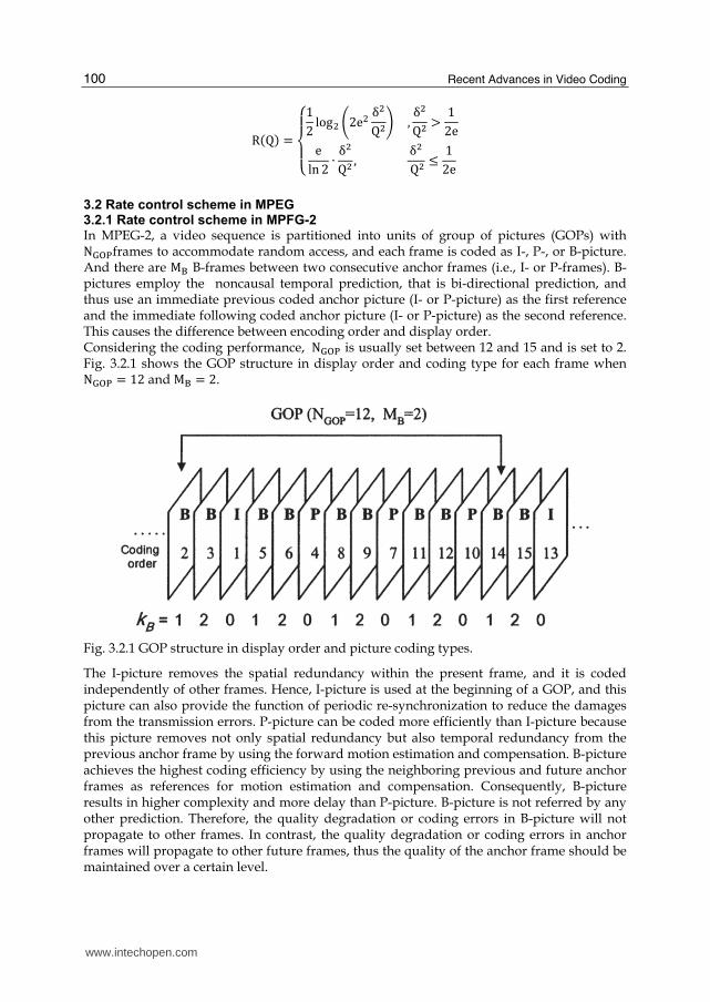
3.2 Rate control scheme in MPEG 3.2.1 Rate control scheme in MPFG-2 In MPEG-2, a video sequence is partitioned into units of group of pictures (GOPs) with N鷹拓沢frames to accommodate random access, and each frame is coded as I-, P-, or B-picture. And there are M台 B-frames between two consecutive anchor frames (i.e., I- or P-frames). B-pictures employ the noncausal temporal prediction, that is bi-directional prediction, and thus use an immediate previous coded anchor picture (I- or P-picture) as the first reference and the immediate following coded anchor picture (I- or P-picture) as the second reference. This causes the difference between encoding order and display order. Considering the coding performance, N鷹拓沢 is usually set between 12 and 15 and is set to 2. Fig. 3.2.1 shows the GOP structure in display order and coding type for each frame when N鷹拓沢 噺 なに and M台 噺 に.
Fig. 3.2.1 GOP structure in display order and picture coding types.
The I-picture removes the spatial redundancy within the present frame, and it is coded independently of other frames. Hence, I-picture is used at the beginning of a GOP, and this picture can also provide the function of periodic re-synchronization to reduce the damages from the transmission errors. P-picture can be coded more efficiently than I-picture because this picture removes not only spatial redundancy but also temporal redundancy from the previous anchor frame by using the forward motion estimation and compensation. B-picture achieves the highest coding efficiency by using the neighboring previous and future anchor frames as references for motion estimation and compensation. Consequently, B-picture results in higher complexity and more delay than P-picture. B-picture is not referred by any other prediction. Therefore, the quality degradation or coding errors in B-picture will not propagate to other frames. In contrast, the quality degradation or coding errors in anchor frames will propagate to other future frames, thus the quality of the anchor frame should be maintained over a certain level.
www.intechopen.com

Rate Control in Video Coding 101
The rate control model in MPEG-2 is TM5, and the rate control model comprises the following three steps:
1. Target bit allocation
This step first allocates bits for given Group of Pictures (GOP) based on the target bit rate and the number of frames in the GOP. Then before encoding of each frame, it allocates bits for that frame based on the frame type (I, P or B), the complexity measure, and the remaining number of bits in the current GOP.
2. Rate control
This is a macroblock level step. Here, a quantization parameter Q is computed for the macroblock j under consideration based on the difference between the allocated bits and the actually generated bits till the encoding of previous macroblock in this picture.
3. Adaptive quantization
This step tries to refine the quantization parameter calculated in Step 2 based on the complexity of the macroblock. For this an "activity measure" of the macroblock is found using variance of the four sub-blocks in the macroblock. The adaptation of the quantization parameter is done to prevent abrupt changes in the quantization parameter and to achieve a more uniform picture quality. To find the spatial activity measure act棚 for the macroblock j using its four sub-blocks,
following computations are done on the intra (i.e . original) pixel values: act棚 噺 な 髪min岫vblkな, vblkに, vblkぬ, vblkね岻 Where vblk樽 is the variance of the nth sub-block and is given by:
vblk樽 噺 な6ね布岫P谷樽 伐 P_mean樽岻態滞替谷退怠
and
P_mean樽 噺 な6ね布P谷樽滞替谷退怠
and P谷 is the sample value in the nth original 8*8blosk.
3.2.2 Rate control scheme in MPFG-4
The MPEG group officially initiated an MPEG-4 standardization phase with mandate to standardize algorithms for audio-visual coding in multimedia applications, allowing for interactivity, high compression, universal accessibility and portability of audio and video contents. Target bitrate for the video standard is between 5±64 k bits/s for mobile applications and up to 4 M bits/s for TV/®lm applications. The MPEG-4 video standard will support the decoding of conventional rectangular images and video as well as the decoding of images and video of arbitrary shape. The coding of frame-based video is achieved similar to conventional MPEG-1/2 coding that involves motion prediction/compensation and texture coding. For the content-based functionalities, where the image sequence input may be of arbitrary shaped and location, this approach is extended by also coding shape information.
www.intechopen.com

Recent Advances in Video Coding 102
Shape may be either represented by an 8-bit transparency component or by a binary mask (Fukunaga et al., 1999; Koenen, 1999; Chiariglione, 1997). According to information theory, two problems are stated: one is source coding (what information should be sent) and the other is channel coding problem (how should it be sent). Rate distortion theory (RDT) is directly related to the source coding problem and that is also related to the lossy image data compression. The key factor in RDT is the rate distortion function (RDF) R(D), which represents the lower bound on the rate: if a certain channel capacity C is given, the RDF can be used to find the necessary minimum average distortion Dave so that the condition for error-free transmission R(Dave) < C is achieved (Schuster et al., 1997). The RDF model shown in Fig. 3.2.2 has been considered as a good choice to represent relations between quantizing distortions and encoder output rates and thus it has been used in wide range. The rate control algorithm based on RDF model (recommended in the MPEG society) has low complexity and yields reasonably good visual quality, however it does not fully exploit the potential of the MPEG standards (MPEG-1, MPEG-2, and MPEG-4).
Fig. 3.2.2 Schematic illustration of the mathematical rate distortion function model of MPEG-4
In typical video coding techniques, the choice of quantizer steps at the encoder plays a key role in determining the actually encoded bitrate and the quality of the transmitted video scenes. MPEG specifies only a decoding method and allows much flexibility in encoding methods. Therefore, the picture quality of the reconstructed video sequence is considerably dependent on the rate control strategy at the encoding process. The recommended rate control algorithm in MPEG, to determine the quantizer steps, consists of three steps namely, bit allocation, rate control, and adaptive quantization based on the mathematical model. In bit allocation, past bit usage and quantizer steps are used to estimate the relative complexity of the three kinds of pictures (I, P, and B) and thereby determine the target bit rate for the
www.intechopen.com

Rate Control in Video Coding 103
present picture. In rate control, a reference quantizer step is determined on a macroblock or frame level by evaluating a virtual buffer status and the difference between the target bit rate and the rate that is already consumed till now. In adaptive quantization, regression based on mathematical model is carried out to decide actual quantizer for the present frame or macroblocks. However, updating the regression procedure using mathematical model needs quite an amount of time and the accuracy may not be predictable. In the MPEG-4 VM rate control algorithm, the quadratic rate distortion model is used to estimate the rate distortion curve to evaluate the target bit rate before performing the actual encoding (Fukunaga et al., 1999):
T 噺 R岫MAD, Q岻 噺 MAD ∙ 岫aな ∙ なQ 髪 aに ∙ なQ態岻 Where, T is denoted as target bits and the mean absolute difference (MAD) is encoding complexity which is sum of absolute difference (SAD) between original image frame and motion compensated reconstructed image frame, and it is already known in the encoding process before rate coding is carried out. And a1 and a2 are the RD modeling parameters that should be updated after finishing encoding process for each image frame. There are five steps in the MPEG-4 VM8 rate control algorithm (Fukunaga et al., 1999): 1. Initialization
ゎな and ゎに are the first and second order coefficients. 2. Computation of the target bit rate before encoding
The computation of target bit rate is based on the bits available and the last encoded frame bits. If the last frame is complex and uses excessive bits, more bits should be assigned to this frame. However, there are fewer number of bits left for encoding thus, these bits can be assigned to this frame. A weighed average reflects a compromise of these two factors.
A lower bound of target bit rate (F/30) is used so that the minimal quality is guaranteed (where F denotes total target bits per second).
The target bit rate is adjusted according to the buffer status to prevent both overflow and underflow.
3. Computation of the quantization parameter (Q) before encoding
Q is solved based on the model parameters, a1and a2. Q is clipped between 1 and 31.
Q varies within 25% of the previous Q to maintain a variable bit rate (VBR) quality. 4. Encoding current frame 5. After encoding, model parameters are updated based on the encoding results of the current
frame.
The rate distortion model is updated based on the encoding results of the current frame. The bits used for the header and the motion vectors are deducted since they are not related to Q.
The data points are selected by using a window
Whose size depends on the change in complexity. If the complexity changes significantly, a smaller window with more recent data points is used.
The model is again calibrated by rejecting the outlier data points. The rejection criterion is the data point and is discarded when the prediction error is more than one standard deviation.
The next frame is skipped if the current buffer status is above 80%.
www.intechopen.com

Recent Advances in Video Coding 104
Fig. 3.2.2 Procedure of the MPEG-4 VM rate control algorithm
3.3 Rate control scheme in H.26x 3.3.1 Rate control scheme in H.263
The rate control model in H.263 is TMN8. In H.263, the current video frame to be encoded is
decomposed into macroblocks of 16_16 pixels per block, and the pixel values for each of the
four 8_8 blocks in a macroblock are transformed into a set of coefficients using the DCT.
These coefficients are then quantized and encoded with some type of variable-length
coding. The number of bits and distortion for a given macroblock depend on the
macroblock's quantization parameter used for quantizing the transformed coefficients. In
the test model TMN8 for the H.263 standard, the quantization parameter is denoted by QP
whose value corresponds to half the quantization step size. The TMN8 rate control uses a
frame-layer rate control to select a target number of bits for the current frame and a
macroblock-layer rate control to select the values of the quantization step-sizes for the
macroblocks. In the following discussions, the following definitions are used:
B : target number of bits for a frame;
R : channel rate in bits per second;
F : frame rate in frames per second;
W : number of bits in the encoder buffer;
M : some maximum value indicating buffer fullness, by default, set R=F;
Wprev : previous number of bits in the buffer;
B` : actual number of bits used of encoding the previous frame.
www.intechopen.com

Rate Control in Video Coding 105
In the frame-layer rate control, a target number of bits for the current frame is determined by
稽 噺 迎繋 伐 ∆ (1)
∆噺 犯激 繋 , 激 伴 傑,警⁄激 伐 傑 ∙ 警, 剣建月結堅拳件嫌結 (2)
激 噺 兼欠捲盤激椎追勅塚 髪 稽嫗 伐 迎 繋, ど⁄ 匪, (3)
Where Z = 0:1 by default. The frame target varies depending on the nature of the video frame, the buffer fullness, and the channel throughput. To achieve low delay, the algorithm tries to maintain the buffer fullness at about 10% of the maximum M. If W is larger than 10% of the maximum M, the frame target B is slightly decreased. Otherwise, B is slightly increased. The macroblock-layer rate control selects the values of the quantization step-sizes for all the macroblocks in the frame, so that the sum of the bits used in all macroblocks is close to the frame target B in (1). The optimized quantization step size 芸沈∗ for macroblock i in a frame can be determined by
Q辿∗ 噺 彪 AKが辿 伐 AN辿C ∙ δ辿ゎ辿布ゎ谷σ谷択谷退辿
Where, K : model parameter; A : number of pixels in a macroblock; Ni : number of macroblocks that remain to be encoded in the frame; σi : standard deviation of the ith macroblock;
i : distortion weight of the ith macroblock; C : overhead rate; βi : number of bits left for encoding the frame, where β1 = B at the initialization stage.
3.3.2 Rate control scheme in H.264
H.264 rate control algorithm adopts a linear prediction model of MAD. Meanwhile, according to Fluid Traffic Model, use rate-distortion function to calculate quantization parameter, and then predict the current processing unit MAD. Rate control can be divided into three levels: GOP level rate control, picture level rate control, the basic unit level rate control. Each level may need to consider the pre-allocation of bits, therefore, how to measure the complexity of each layer is the key. Distribute pre-allocation bits to each level according to the complexity of each level, and then set the quantization parameters. Therefore, complexity and how to set reasonable QP value, is particularly critical.
3.3.2.1 GOP level rate control
GOP level rate control calculates the remaining bits for the rest pictures, and initializes the quantization parameter of the first picture (I or P) in the current GOP. When the 倹痛朕picture in the 件痛朕GOP is coded, the number of total bits for the restpictures in this GOP is computed as follows,
www.intechopen.com

Recent Advances in Video Coding 106
稽沈岫倹岻 噺 菌衿芹衿緊 迎沈岫倹岻血 抜 軽沈 伐 撃沈岫倹岻 倹 噺 な稽沈岫倹 伐 な岻 髪 迎沈岫倹岻 伐 迎沈貸怠岫倹岻血 抜 岫軽沈 伐 倹 髪 な岻 伐 決沈岫倹 伐 な岻 倹 噺 に,ぬ… (4)
Where f is the predefined frame rate, 軽沈is the size of the件痛朕GOP, R沈岫j岻, B沈岫j岻and V沈岫j岻 are the instant available bit rate, actual generated bits and occupancy of the virtual buffer for the倹痛朕picture in the 件痛朕GOP, respectively. For the first picture (j = 1) in a GOP, the number of remaining bits calculated from the upper formula in (4) is the allocated bits for the current GOP in fact. Besides, the instant available bit rate R沈岫j岻can be variable for the different frames or GOPs Considering the VBR case, while in the CBR case, R沈岫j岻 is always equal to R沈岫j 伐 な岻 and (4) can be simplified as: 稽沈岫倹岻 噺 稽沈岫倹 伐 な岻 伐 決沈岫倹 伐 な岻 (5)
Initially, the virtual buffer is filled by the motion bits generated previously in the MCTF, so the occupancy of virtual buffer is initialized as M沈岫l岻which presents the motion bits of the 倹痛朕picture in the 件痛朕 GOP. Except the first GOP, besides initial motion bits, the virtual buffer’s occupancy of the last GOP coded also is considered as upper formula (6) shown. After a picture coded, the V沈岫j岻 is updated as bottom formula (6):
撃沈 噺 崕兼沈岫な岻 件 噺 な撃沈貸怠盤軽沈貸怠 髪兼沈岫な岻匪剣建月結堅撃沈岫倹岻 噺 撃沈岫倹 伐 な岻 髪 決沈岫倹 伐 な岻 伐 迎沈岫倹 伐 な岻血 倹 噺 に,ぬ…軽沈 (6)
Besides bit allocation, the initial quantization parameter decision is also included in the GOP level rate control. For the first GOP, the predefined quantization parameter specified for motion estimation/mode decision in the MCTF is used as the initial quantization parameter for simplicity. For other GOPs, the initial quantization parameter is predicted as follows,
芸鶏沈岫な岻 噺 嫌憲兼芸鶏岫件 伐 な岻な 髪 軽沈貸怠椎 (7)
Where sumQP(i-1) is the sum of average QP for all I/P pictures in the (i-1)th GOP, and 軽沈貸怠椎is the total number of P pictures in the (i-1 )the GOP.
3.3.2.2 Picture level rate control
Picture level rate control allocates target bits for each picture based on the remaining bits, picture’s complexity and virtual buffer’s occupancy. Getting the target bits and MAD of current picture, the quantization parameter can be obtained based on the R-D model15. The MAD of a block A of size N×N located at (x, y) inside the current picture compared to a block B located at a displacement of (vx, vy) relative to A in a previous picture is defined as:
警畦経岫捲, 検岻 噺 な軽態 布 |繋沈岫捲 髪 兼, 検 髪 券岻繋沈岫捲 髪 懸掴 髪兼, 検 髪 懸槻 髪 券岻弁朝貸怠陳,津退待 (8)
Where Fi is the current picture and Fi-t is a previously coded picture. In our proposed rate control algorithm, the picture level rate control consists of two stages: pre-encoding and
www.intechopen.com

Rate Control in Video Coding 107
post-encoding. In the pre-encoding stage, QP decision for each picture are accomplished with virtual buffer considerations, while in the post-encoding stage, the models updating with the statistical results is implemented.
3.3.2.1.1 Pre-encoding stage
In this stage, the quantization parameter of each picture is calculated. Firstly, the target bits are allocated for the current picture, and then the quantization parameter for the current picture can be obtained with the pre-defined rate distortion (R-D) model. The target bit allocation should both consider the occupancy of virtual buffer and remaining bits for the rest pictures. Firstly, smoothing the occupancy of virtual buffer by regulating bit rate arriving, the target bits allocated for the 倹痛朕 picture in the 件痛朕 GOP based on instant bit rate and the occupancy of virtual buffer are determined as:
T 沈岫倹岻 噺 峭な 伐 撃沈岫倹 髪 な岻 伐 撃沈岫倹岻撃沈岫倹岻 抜 迎沈岫倹岻血 嶌 (9)
Secondly, remaining bit allocation for the 倹痛朕 picture in the 件痛朕 GOP is computed as:
T̂ 沈痛岫倹岻 噺 X̂ 沈痛 抜 稽沈岫倹岻∑ 計痛 抜 X̂ 沈痛岫倹岻 抜 軽痛,追痛退椎,長 (10)
Where 軽椎,追, and 軽長,追, are the number of the remaining I/P pictures and the number of the
remaining B pictures ,respectively, X沈痛(j)is the predicted complexity measure for the current coding picture, and Kp/Kb is the ratio of I picture’s QP and P/B picture’s QP regulated with the selected wavelet function in the MCTF1. The complexity measure is the product of target bits and average QP for a picture (basic unit or MB). For pictures with type B, the complexity can be determined beforehand, while for the pictures with type I/P, the complexity only can be predicted from the nearest picture coded previously. After coding a picture in the 件痛朕 GOP, the actual generated bits and average QP can be obtained, and then, the complexity measure is updated as: 隙沈岫倹岻 噺 糠 抜 決沈岫倹 伐 な岻 抜 欠懸訣芸鶏沈岫倹 伐 な岻 (11)
Where avgQPi(j-1) is the average of quantization parameters of the previously coded picture, is a constant and set as 0.9 when next picture is P type otherwise set as 1 in our experiments. Specially, in the SVM, the pictures with type of I or P both are the temporal low sub-band pictures, and also except the first GOP with one I and one P pictures, only one I or P picture is in a GOP, so the complexity of I/P picture in the next GOP shall be predicted from that of I/P picture in the previously coded GOP. In conclusion, the predicted complexity measure is computed as:
X̂ 沈痛 岫倹岻 噺 崔隙沈貸怠岫な岻 建 噺 件; 喧, 件 塙 な隙沈岫な岻 建 噺 件; 喧 , 件 噺 な隙沈岫倹岻 建 噺 決 (12)
Lastly, the parameter of target bits is determined with a weighted combination of 劇彫風岫倹岻 and 劇徹撫岫倹岻 jˆ ( ) (1 ) ( )i i iT T j T (13)
www.intechopen.com
Recent Advances in Video Coding 108
Where β is a constant and set as 0.9 in our experiments. To conform to the virtual buffer requirement, the target bits are further bounded by: 劇沈岫倹岻 噺 兼件券岶戟沈岫倹岻,兼欠捲岶傑沈岫倹岻, 劇沈岫倹岻岼岼 (14)
Where Zi(j) and Ui(j) are the minimum buffer constraint and maximum buffer constraint for preventing buffer from overflow and underflow. Same as the state-of-the-art hybrid coding, at least a picture needs buffering for decoding successfully. At the same time, the maximum buffer constraint is set as (16) avoiding buffer overflow.
戟沈岫倹岻 噺 畔稽沈貸怠岫軽沈貸怠岻 髪 建追,怠岫な岻 抜 迎沈岫な岻 倹 噺 な戟沈岫倹 伐 な岻 髪 蕃迎沈岫倹岻血 伐 決沈岫倹岻否 剣建月結堅 (15)
傑沈岫倹岻 噺 菌衿芹衿緊 稽沈貸怠岫軽沈貸怠岻 髪 迎沈岫倹岻血 倹 噺 な傑沈岫倹 伐 な岻 髪 蕃迎沈岫倹岻血 伐 決沈岫倹岻否 剣建月結堅 (16)
Where tr,1(1) is the removal time of the first picture from the coded picture buffer. Getting the target bits for a picture, the QP can be obtained with pre-defined R-D model. After motion estimation and mode selection in the MCTF (pre-mode-decision), the MAD of I/P pictures is still unable to be determined, so it is predicted from the closet picture coded previously by a linear model,
( ) 1 ( 1) 2ij a j a (17)
Where a1 and a2 are two coefficients with initial values 1 and 0. And then, the quantization parameter corresponding to the target bits is computed as:
,2
( ) ( )( ) 1 2 ( )
( ) ( )i i
i h ii i
j jT j c c m j
QP j QP j
(18)
Where mh,i(j) is the total number of header bits and motion vector bits, c1and c2are two coefficients. Since a drop in peak signal-to-noise ratios (PSNR) among successive pictures will deteriorates the visual quality of the whole sequence, the quantization parameter QPi(j) is adjusted by:
1 -1(1) max{ (1) - 2,min{ (1) 2, (1)}}i i i iQP QP QP QP (19)
With such modifications, the difference in PSNR is not more than 2 between two successive pictures. And more, considering QP boundary in the SVM, the final quantization parameter is further bounded by 51 and 0. The quantization parameter is then used to perform quantization for each MB in the current picture. Specially, for B pictures, the MAD can be calculated from the current picture except intra block determined in the MCTF. The quantization parameter corresponding to the target bits is then calculated by using the formula (18). But for the intra blocks in B pictures, the MAD can’t be obtained, and also is unreasonable predicted from any coded picture; however, only few intra blocks lie in a B picture. When pre-mode-decision is implemented, those intra modes can be recorded.
www.intechopen.com
Rate Control in Video Coding 109
Therefore, the MAD of the current intra block can be calculated approximately based on the recorded information in the pre-mode-decision stage.
3.3.2.1.2 Post-encoding stage
After encoding a picture, the parameters a1 and a2 of linear prediction model (17), as well as c1 and c2 of quadratic R-D model (18) are updated with a linear regression method similar to MPEG-4 Q226,27. Meanwhile, the remaining bits for the rest pictures Bi(j) is updated using (5).
3.3.2.3 Basic unit level rate control
Basic unit is defined to be a group of continuous MBs. It is used to obtain a trade-off between the overall coding efficiency and the bits fluctuation. The basic unit level rate control is similar to the picture level rate control, including MAD prediction, bit allocation, and quantization parameter decision in basic unit level. In our simulating system, the spatial layers with different resolutions from QCIF (176×144) to 4CIF (704×576) are coded for a same video clip. Generally, the basic unit level rate control is efficient for the large size pictures (>QCIF) from our experience.
Firstly, the MAD of the l th basic unit is calculated in the current coding picture. In case I/P pictures, the predictive ,, ( )l iMAD j ,is obtained by model (17) using the actual MAD of co-located basic units in the picture coded previously. In case B pictures, the MAD of current basic unit can be calculated directly. Secondly, determining the target bits for the lth basic unit is implemented as follows,
,
2
2,
( )ˆ
( )
l i
l r Nunitn in l
lb T
k
(20)
Where Tr is the remaining bits for the rest basic units in the current picture, and initialized as the picture target bits Ti(j). Thirdly, the quantization parameter QP狸,辿岫j岻 for the lth basic
unit of jth picture in ith GOP is calculated using the quadratic R-D model (18), and then bounded by: 芸鶏鎮,沈岫倹岻 噺 兼欠捲岶芸鶏鎮貸怠,沈岫倹岻 伐 経芸憲欠券建,兼件券岶芸鶏鎮,沈岫倹岻, 芸鶏鎮貸怠,沈岫倹岻 髪 経芸憲欠券建岼岼 (21)
Where DQuant is a constant, and generally is regulated with the quantization parameter. In our experiments, DQuant is 1 if QP狸貸怠,辿岫j岻 is greater than 27, otherwise is 2. Meanwhile, to
maintain the smoothness of visual quality, (21) is further bounded by
, ,( ) max{0, ( 1) 6,min{51, ( 1) 6, ( )}}l i i i l iQP j QP j L QP j L QP j (22)
Specially, for the first basic unit in the current picture, the QP can be derived from average QP of all basic units in the previously coded picture,
芸鶏沈岫倹岻 噺 糠 抜 嫌憲兼芸鶏沈岫倹 伐 な岻軽通津沈痛 (23)
Where N探樽辿担 is the number of basic unit in this picture, is a constant as provided in (11). When the number of remaining bits is less than 0, the QP is set as: 芸鶏鎮,沈岫倹岻 噺 芸鶏鎮貸怠,沈岫倹岻 髪 経芸憲欠券建 (24)
www.intechopen.com
Recent Advances in Video Coding 110
Similarly, the QP is further bounded by (20) to maintain the smoothness of perceptual quality. Lastly, the QP is used to perform RDO for all MBs in the current basic unit. After coding a basic unit, the number of remaining bits, the coefficients of linear prediction model (17) and quadratic R-D model (18) are updated.
4. Development of rate control method
4.1 The development of rate control The video compression technology has more than 30 years of development history. However, it hadn’t made great success and got a wide range of applications until CCJTT approved H. 261 standard in 1988. With the development of the video compression, the MPEG-1, MPEG-2, H.263, MPEG-4 and H.264 and so on had been proposed as the standards of the video compression. Rate control is one of the key technologies of the standards, has a great effect on the systems of the video compression. In1990, the H.261 has been proposed, and the rate control model is RM8 (Reference Model 8). It proposed a simple algorithm to control rate, but the result is not very well. In 1994, the Moving Picture Experts Group proposed the MPEG-2, and its rate control model is TM5 (Test Model 5). MPEG-2 didn’t propose the concrete realization method, but it proposed and integrated the algorithm of rate control in TM5. The rate control concluded 3 steps: target bit allocation, rate control and adaptive quantization. However, this model didn’t take the problems into consideration, which was caused by dealing with scene switch. As a result, the quality of different macroblock in the same frame was different and the reference QP had a big difference with the actual QP in the algorithm. In order to control the bitrate more effective, MPEG-4 adopted VM8 (Verification Model 8) to realize rate control in 1998. The thought that there is a strong connection between the neighboring frames and the R-D relation of the coded frames which can be used to predict the encoding frames was used by VM8, and it worked well in the video with low movement. However, when there were many scene switches and changes in the video, the efficiency of the algorithm decreased. At the same year, The H.263 had been proposed, and the TMN8 (Test Model Near-Term 8) was used in the rate control. TMN8 has two steps: the bits allocation in the frame layer and the adaptive quantization in the macroblock layer. Compared to the VM8, TMN8 can realize the rate control more accurately, thereby maintaining the stability of the buffer. However, the TMN8 didn’t adjust the dynamic quantization parameter to each macroblock, especially can’t realize rate control effectively under the condition of the scene switch. The latest video coding H.264 standard was proposed in 2003, and the rate control method is different from the previous approaches in that the QP values are chosen prior to the prediction taking place. More specifically, the existence in the H.264 standard of a number of coding modes for each MB - multiple inter and intra modes - and the use of rate distortion optimization in the JM encoder for selecting one makes the application of typical rate control strategies quite problematic. Most of the previously mentioned rate control methods rely on a rate model and a distortion model for choosing an optimal quantiser for each macroblock or frame, given a measure of the variance of the residual signal (the prediction difference signal) and a specific bit budget allocation. The rate model is used to predict the number of bits output after coding a macroblock or frame with a specific quantiser and the distortion model is used to predict the distortion associated with each quantiser. Lagrangian optimisation can then be employed to choose the best QP in a rate distortion sense. The problem with the JM H.264 encoder lies with the fact that the residual signal depends on the choice of coding mode and the choice of coding mode depends on the choice of QP which in turn depends on
www.intechopen.com
Rate Control in Video Coding 111
the residual signal (a chicken and egg type of problem). The adopted solution in the JM encoder is one where the choice of QP is made prior to the coding mode decision using a linear model for predicting the activity of the residual signal of the current basic unit (e.g. frame, slice, macroblock) based on the activity of the residual signal of past (co-located) basic units. Though the rate control in H.264 works well in the rate control, there are some aspects to make rate control more effectively and accurately which are worth studying.
4.2 The direction of the development
In the video compression, rate control plays an important role. Because the video quality of the output is related to the bitrate, in order to get a better quality in the video, the output bitrate will be higher. But because of the limited bandwidth or the capacity of the storage, it is required to keep the output bitrate in a certain range to meet the limited of the bandwidth or the capacity of the storage and get as better video quality as possible. So the strategy of the rate control is one of the key success factors of the video encoding. The purpose of the rate control is getting a better video quality in the limited bandwidth or storage. In order to achieve the goal, the rate control usually has two steps: the allocation of the resources and the calculation of the QP. The allocation of the resources researches the rate control from the angle of from top to bottom, stresses the reasonable allocation of the coding resources among the different frames (the rate control of single sequence) or different sequences (the rate control of the joint sequences); the calculation if the QP researches the rate control in the angle of from bottom to top, chooses the coding mode within the limited of the coding resources based on the rate distortion model and the RDO (rate distortion optimization) in order to make the actual rate and the target rate consistent. The current video compression standards only make strict restrictive provisions for the streaming grammar, streaming multiplexing and decoding process and so on which are relevant to the compatibility. However, they don’t make strict restrictive provisions for the aspects such as motion estimation and rate control and so on which have an important influence on the coding, but have little effect on the compatibility. As a result, they provide a large space to developers, manufacturers and research workers to improve the quality of the coding. The fundamental tenet of the design of the rate control is determining the appropriate coding parameters to obtain optimal decoding video quality under the limited bandwidth. Though there are many effective rate control schemes nowadays, the requirements on the quality of the video images are higher and higher. As a result, the methods of the rate control should get further developments and improvements. We think the future rate control technology in the following respects will get further development.
1. The more accurate rate distortion model
The key problem of the rate control is to estimate or model the rate-distortion model of the video encoder, there are some rate distortion models put forward in the existing documents, but these models are usually assumed source obey Gaussian distribution or Laplace distribution, and when the actual video does not satisfy assumptions, the accuracy of the model will be affected and the quality of the algorithms will decrease. Furthermore, the application scope of some models is very small, because they are usually only for the fixed encoder and not accurate for the rest encoder. Therefore, it is necessary to propose more accurate rate distortion models which are suitable for various video encoders and can reflect the features of the actual video sequences rate-distortion accurately.
www.intechopen.com

Recent Advances in Video Coding 112
2. The more reasonable control strategy to buffer
In order to prevent buffer overflow or underflow, the consideration in many documents is
making the occupancy degree of the buffer is about 50% when each frame has been coded.
The rate control in MPEG-4 keeps the capacity of the buffer not less than 10% and more than
90% by skipping the frame in the stage of the bit allocation to each frame when the occupancy
degree of the buffer is more than 80% after the previous frame has been coded. However,
the bits of I frame are more than the bits of P or B frame several times, so setting the occupy
degree to a fixed value is not a scientific approach. If it can adjust the buffer occupancy
degree to a more reasonable value adaptively based on the situation of the encoder, it not
only can deal with the buffer overflow, but also can avoid the skip frames where possible.
3. The processing of the scene switch
In the real-time video applications, the complexity of the video sequences is changing. In
order to adapt to the scene switch, the method of adjusting the size of GOP dynamically and
the method of testing the scene switch have been proposed to give special treatment to the
pictures with scene switch. But these methods are usually not accurate, and the computations
are complex. Therefore, putting forward a more accurate detection method and the reasonable
allocation method to the scene switch pictures is a meaningful work.
4. The rate control algorithm based on the wavelet video encoder
The wavelet encoder has some advantages: (a). providing a better compromise of R-D; (b).
providing a satisfactory subjective image quality; (c). having the character that the
interception bits at any point won’t cause serious distortion; (d). there is no need to consider
the quantification parameters and just only to allocate reasonable bits to each frame. The
rate control methods based on the wavelet are simpler than the methods based on DCT, and
can be adjusted more easily. The rate control researches relative to the MPEG are very few
now, but with the application of the wavelet transform in the video coding and video
information transmission, the direction will become a hotspot.
5. The rate control algorithm based on the video object
Since MPEG-4 based on video object proposed, many scholars have researched the rate
control based on video object and have put forward some effective rate control algorithms.
But most of these algorithms are just the continuation of the methods based on the signal
video object and not very accurate. The solution to allocate reasonable bits based on video
object, the information of shape and motion vector plays an important role in the quality of
the decoding pictures. With the wide application of video information based on video
object, the rate control algorithm based on video object will get a good development.
6. The fine granularity scalable rate control allocation algorithm
The initial goal of the video coding is achieving the optimal decoding quality at the given
bitrate, because of the increase in Internet video services in recent years, the goal of the
video coding is not just to pursue the best video quality and pay more and more attention to
the scalability. Nowadays, it has appeared many effective fine granularity scalable rate
control algorithms, and many scholars have been working to improve and develop fine
granularity scalable encoding technology. How to design a scalable rate control algorithm
adapted to various fine granularity, how to allocate bits to basic and strengthen layers; how
to allocate bits in the strengthen layers, which can achieve scalable requirements and can
www.intechopen.com

Rate Control in Video Coding 113
obtain more satisfactory video effect. These are the important problems to solve in the
further researchers.
7. The rate control algorithm in the real-time communication of low bitrate
The main challenge in the design of multimedia applications in communications network is how to transmit the smallest multimedia streaming to users. The real-time communication applications such as video conference, online ordering require the rate control scheme with low latency and low complexity. The methods based on the optimization of Lagrange have existed in the documents, but they are of high complexity. Simplifying the complexity of the methods to make them meet the requirements of the real-time communication applications has high theoretic and commercial value. In addition, some of the rate control methods are based on the content of the pictures and the visual characteristic. Compared to the rate-distortion scheme, they are relative simple and easy to realize, but they are not very accurate and need to continue to improve.
5. Acknowledgement
this chapter is supported by the National Basic Research Program of China (973 Program, No. 2010CB731800), Key Program of National Natural Science Foundation of China (No.U0835003, 60804051), the Fundamental Research Funds for the Central Universities of SCUT (2009ZM0207), the Doctoral Fund of Ministry of Education of China (200805611074)
6. Reference
A. H. Compressed video communication. Jozadak. Beijing: science press. 2004 Asbun E, Salama P. Delp E J. A rate-distortion approach towavelet-based encoding of
predictive error frames [A]. In: Proceedings of the 2000 IEEE International Conference on ImageProcessing [C], Vancouver, British Columbia, Canada, 2000: lO~13.
Atul Puri, Xuemin Chen, Ajay Luthra. Video Coding Using the H.264/MPEG-4 AVC Compression standard. Signal Processing: Image Communication.
Chem. Hang. H.M. Source model for transform video coder and its application-partll: variable frame rate coding. IEEE Trans. Circuit and Syst. Video Technol. 1997, 7(2):299-311
Chiang T., Zhang Y Q. A new rate control scheme using quadratic rate distortion model [J]. IEEE Transactions on Circuits and Systems for Video Technology. 1997, 7(1):246-250.
Choi J, Park D. A stable feedback control of the buffer state using the controlled langrange muhiplier method [J]. IEEE Transactions on Image Processing.1994, 3:546-558
Dins W, Liu B. Rate control of MPEG video coding and recordins by rate quantization modeling [J]. IEEE Transactions on Circuits and Systems for Video Technology, 1996, 6(1):12-20.
Farin D, Mache N, P.H.N. de With. A software-based high quality MPEG-2 encoder employing scene change detection and adaptive quantization [J]. IEEE Transactions on Consumer Electronics, 2002, 48(4): 2174-2193
G. Sullivan, T. Wiegand, Keng-Pang Lim, "Joint Model Reference Encoding Methods and Decoding Concealment Methods", JVT-1049, September 2003
www.intechopen.com
Recent Advances in Video Coding 114
Hung-Ju Lee, Ya-Qin Zhang. Scalable Rate Control for MPEG-4 Video. IEEE Trans. Circuits 64 and Systems for Video Technology2000, 10(6): 878-894
ISO/IEC JTC1/SC2/WG11, “MPEG Video Simulation Model Three (SM3),” MPEG 90/041, July 1990.
ISO/IEC JTC1/SC29/WG11/Doc.N3093. MPEG-4 video verification model version 15.0. Dec. 1999.
ISO/IECJTCl/SC29/WG11.MPEG99/M5552. An all FGS Solution for Hybrid Temporal-SNR Sealability[S]
ISO/IEC/IECJTC/29/WG11.MPEG2000/M6475,Motion-compensation Based Fine-granuhr Scalability (MC-FGS) [S]
ISO/IEC JTC/SC29/WGl 1.MPEG 97/M1931. Joint rate control for multiple video objects based on quadratic rate-distortion model[s].
ISO/IEC J'rcI/SC29/WGll. MPEG97/M2554.Multiple.VO rate control and B-VO rate control[s]
ISO/IEC 14496-2/PDAM4, Coding of Audio-Visual Objects, Part-2 Visual, Amendment4: Streaming Video Pmfile[S]
Jay Kuo C C., Leou J J. A newrate control scheme for H.263 video transmission [J]. Singal J. Ribas-Conklin, S. Lei. Rate control in DCT video coding for low-delay communication.
IEEE Trans. Circuit Syst. Video Technol. Feb 1999, 9(1):172-185 Kondi L P, Melnikov G, Katsaggeles A K. Joint optimal coding of texture and shape [A]. In:
Proceedings of IEEE International Conference on Image Processing[C], Thessaloniki, Greece, 2001, 3:94-97.
Lain E., G. Richardson. H.264 and MPEG-4 Video Compression Video Coding for Next Generation Multimedia. UK. John Wiley&Sons Ltd. 2003
Lee J., Dickinson B. W. Joint optimization of frame type selection and bit allocation for MPEG video encoders [A]. In: Proceedinss of International Conference on Image Processing 1994[c], Austin TX, USA, 1994: 962-966.
Li Wei-ping. Overview of fine granularity scalability in MPEG-4 video standard [J]. IEEE Transactions on Circuits and Systems for Video Technology. 2001, 11(3):301-317.
Lin D W, Wang M. H., Chen J. J. Optimal delayed·coding of video sequences subject to a
buffer-size constraint [A]. In: Proceedings of SPIE Visual Communication and Image Processing 1993[C], Cambridge. MA, USA, 1993: 223-234
Lin L J., Ortega A., Jay Kuo C C. Rate control using spline- interpolated R.D characteristics [A]. In: Proceedings of Visual Communications and Image Processing 1996[c], Orlando. FL, 1996:11I-122.
Liu Hong-mei, Xiao Zi-mei, Liang Fan, et al. Resoaroh on rate scalable wavelet video coding algorithm [J]. Journal of Software, 2002, 13(4):664-668.
Liu Jiu·fen., Huang Da. ren. A rate control method based on wavelet transform [J]. Journal of
Zhejiang University (Sciences Edition), 2001, 28(01):14一18
M. Van der Schaar, Radha H. Adaptive motion. Compensation Fine-Granular-Scalability (AMC-FGS) for wireless video [J]. IEEE Transactions on Circuits and Systems for Video Technology, 2002, 12(6): 360-371
MPEG 93/457, Document AVC-491, April 1993. MPEG-1 AND MPEG-2 Video Standards By Supavadee Aramvith and Ming-Ting Sun Processing: Image Communication, 2002, 17(7):537-557 ISO/IEC JTC1/SC29/WG11, “Test
Model 5”,
www.intechopen.com
Rate Control in Video Coding 115
Proposed draft of adaptive rate control. JVT H017. 8`s Meeting: Geneva, 20-26. May, 2003 Ramchandron K., Ortega A., Vetterli M. Bit allocation for dependent quantization with
applications to muhire solution and MPEG video coders C [J]. IEEE Transactions on Image Processing, 1994, 3:533-545
Ribas-Corbera J., Lei S. Rate control in DCT video coding for lowdelay communications [J]. IEEE Transactions on Circuits and Systems for Video Technology, 1999, 9(1): 172-i85
Ronda J, Eckert M, et al. Rate control and bit allocation for MPEG-4. IEEE Trans. Circuit Syst. Video Technol. 1999, 9(8): 1243-1258
Sethuraman S, Krishnamurthy R.Model based multi-pass macroblock-level rate control for visually improved video coding [A]. In: Proceedings of Workshop and Exhibition on MPEG-4 [c], San Jose, California, USA, 2001: 59-62
Shi Cui-zu. Yu Song·yu. Wang Jia. Rate allocation for MPEG-4 FGS video streaming [J].
Computer Simulation, 2004, 21(6): 46-55. Tao B, Peterson H A, Dickinson B W. A rate. quantiration model for MPEG encoders [A]. In:
Proceedings of International Conference on Image Processing 1997 [c], Santa Barbara, CA USA, 1997:338~341.
T. Chiang and Y.-Q. Zhang, "A new rate control scheme using quadratic rate-distortion modelling", IEEE Trans. on Circ. and Syst. for Video Tech., Feb. 1997.
Vetro A, Sun H, Wang Y. Joint shape and texture rate control for MPEG-4 encoders [A]. In: Proceedings of IEEE International Conference on CireuRs and Systems[C], Montery, USA. 1998:285-288.
Wang Hut-bai, Zhang Chun Tian. A buffer control strategy based on importance of the image eontents [J]. Journal of China Institute of Communications, 2000, 21(8): 21-26
Wang O, Wu F, Li S P, et al. Fine-granularity spatially scalable video coding [A]. In: proceedings of IEEE International Conference on Acoustics, Speech and Signal Processing (ICASSP)[C], Salt Lake City, 2001,3:1801-1804
Wang Qi, Zhan Li, Wu Feng, et al. A rate allocation scheme for progressive fine granular scalable video coding [J]. Acts Electronica Sinica. 2002, 30(2):205-209.
Wang L. Rate control for MPEG video coding [J]. Signal Processing: Image Communication, 2000. 15:493-511
Watson A B, Yang G Y, Solomon J A, et al. Visibility of wavelet quantization noise [J]. IEEE Transactions on Image Processing, 1997, 6(8):1168-1175.
Wu F., Li S., Zhang Y. Q. A framework for efficient progressive fine granularity scalable video coding [J]. IEEE Transactions on Circuits and Systems for Video Technology, 2001. 11(3):332-344.
Wu S W., Gersho A. Rate constrained optimal block-adaptive coding for digital tape recording of HDTV [J]. IEEE Transactions on Circuits and Systems for Video Technology. 1991, 1(1):100-112
Yang K H, Jacquin A, Jayant N S. A normalized rate-distortion model for H.263 compatible codecs and its application to quantisor selection [A]. In: Proceedings of International Conference on Image Processing 1997 [C], Santa Barbara, CA, USA, 1997: 41-44.
Yeo B, Liu B. Rapid scene analysis on compressed video [J]. IEEE Transactions on Circuits and Systems for Video Technology, 1995, 5(6):533-544
www.intechopen.com

Recent Advances in Video Coding 116
Yoneyama A., Nakajima Y., Yanagihara H., et al. MPEG encoding algorithm with scene adaptive dynamic GOP structure[A]. In: Proceedings of Ostermann J.Multimedia Signal Processing---1999 IEEE 3” Workshop on [c], Copenhagen: IEEE Pres. 1999: 297-302
Zhao X. J., He Y. W., Yang S. Q., et al. Rate allocation ofequal image quality for MPEG-4 FGS video streaming [EB/OL]. http://amp.ece.cmu.edu/packetvide02002/papers/32-uwsghuasts.poe 2002.
Zhengguo Li, Feng Pan, Keng Pang Lim, Xiao Lin, Susanto Rahardja, "Adaptive Rate Control for H.264", ICIP 2004.
Zhihai He, Yong Kwan Kim, et al. Low-Delay Rate Control for DCT Video Coding via ρ-Domain Source Modeling. IEEE Trans. Circuits and Systems for Video Technology, 2001, 11(8): 928-940
Zhihai He, Sanjit K, et al. A Unified Rate-Distortion Analysis Framework for Transform Coding. IEEE Trans. Circuits and Systems for Video Technology, 2001, 11(12): 1221- 1236.
Zhengguo Li, Feng Pan, Keng Pang Lim, et al. Adaptive Basic Unit Layer Rate Control for JVT JVT 6012. 7a' Meeting: Pattaya II, Thailand. March, 2003
www.intechopen.com

Recent Advances on Video CodingEdited by Dr. Javier Del Ser Lorente
ISBN 978-953-307-181-7Hard cover, 398 pagesPublisher InTechPublished online 24, June, 2011Published in print edition June, 2011
InTech EuropeUniversity Campus STeP Ri Slavka Krautzeka 83/A 51000 Rijeka, Croatia Phone: +385 (51) 770 447 Fax: +385 (51) 686 166www.intechopen.com
InTech ChinaUnit 405, Office Block, Hotel Equatorial Shanghai No.65, Yan An Road (West), Shanghai, 200040, China
Phone: +86-21-62489820 Fax: +86-21-62489821
This book is intended to attract the attention of practitioners and researchers from industry and academiainterested in challenging paradigms of multimedia video coding, with an emphasis on recent technicaldevelopments, cross-disciplinary tools and implementations. Given its instructional purpose, the book alsooverviews recently published video coding standards such as H.264/AVC and SVC from a simulationalstandpoint. Novel rate control schemes and cross-disciplinary tools for the optimization of diverse aspectsrelated to video coding are also addressed in detail, along with implementation architectures specially tailoredfor video processing and encoding. The book concludes by exposing new advances in semantic video coding.In summary: this book serves as a technically sounding start point for early-stage researchers and developerswilling to join leading-edge research on video coding, processing and multimedia transmission.
How to referenceIn order to correctly reference this scholarly work, feel free to copy and paste the following:
Zongze Wu, Shengli Xie, Kexin Zhang and Rong Wu (2011). Rate Control in Video Coding, Recent Advanceson Video Coding, Dr. Javier Del Ser Lorente (Ed.), ISBN: 978-953-307-181-7, InTech, Available from:http://www.intechopen.com/books/recent-advances-on-video-coding/rate-control-in-video-coding
Related Documents


![Video Coding Concept - NCTU - MAPLmapl.nctu.edu.tw/course/SMSDI_2014/files/[1]Video Coding Concept.pdf · Raw data rate of HDTV video ... “Rate-Constrained coder control and comparison](https://static.cupdf.com/doc/110x72/5b5439727f8b9aa40e8cb903/video-coding-concept-nctu-1video-coding-conceptpdf-raw-data-rate-of-hdtv.jpg)