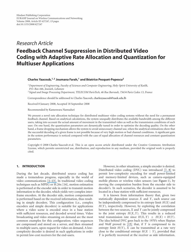
Hindawi Publishing Corporation EURASIP Journal on Wireless Communications and Networking Volume 2008, Article ID 427247, 13 pages doi:10.1155/2008/427247 Research Article Feedback Channel Suppression in Distributed Video Coding with Adaptive Rate Allocation and Quantization for Multiuser Applications Charles Yaacoub, 1, 2 Joumana Farah, 1 and B ´ eatrice Pesquet-Popescu 2 1 Department of Engineering, Faculty of Sciences and Computer Engineering, Holy-Spirit University of Kaslik, P.O. Box 446, Jounieh, Lebanon 2 Signal and Image Processing Department, TELECOM ParisTech, 46 Rue Barrault, 75634 Paris Cedex 13, France Correspondence should be addressed to Charles Yaacoub, [email protected] Received 8 January 2008; Accepted 18 September 2008 Recommended by Kameswara Namuduri We present a novel rate allocation technique for distributed multiuser video coding systems without the need for a permanent feedback channel. Based on analytical calculations, the system unequally distributes the available bandwidth among the different users, taking into account the actual amount of movement in the transmitted video as well as the transmission conditions of each user. On one hand, the quantization parameters are dynamically tuned in order to optimize the decoding quality. On the other hand, a frame dropping mechanism allows the system to avoid unnecessary channel use, when the analytical estimations show that the successful decoding of a given frame is not possible because of very high motion or bad channel conditions. A significant gain in the system performance is noticed compared with the case of equal allocation of channel resources and constant quantization parameters. Copyright © 2008 Charles Yaacoub et al. This is an open access article distributed under the Creative Commons Attribution License, which permits unrestricted use, distribution, and reproduction in any medium, provided the original work is properly cited. 1. INTRODUCTION During the last decade, distributed source coding has made a tremendous progress, especially in the world of video communications [1–13]. In traditional video coding techniques such as MPEG or H.26x [14], motion estimation is performed at the encoder side in order to transmit motion information to the decoder, which yields very complex inter- frame encoders. At the decoder side, motion compensation is performed based on the received information, thus result- ing in simple decoders. This configuration (i.e., complex encoders and simple decoders) is suitable for applications where a video scene is encoded once in a base station with sufficient resources, and decoded several times. Video broadcasting and video streaming on demand are the most common examples for this configuration; video sequences are compressed and stored on a server, and then streamed to multiple users, upon request for video on demand. A low- complexity decoder is desired in such applications in order to permit low-cost receivers for the end-users. However, in other situations, a simple encoder is desired. Distributed video coding (DVC) was introduced [7, 8] to permit low-complexity encoding for small power-limited and memory-limited devices, such as camera-equipped mobile phones or wireless video sensors (see Figure 1), by moving the computation burden from the encoder side to decoder’s. In such scenarios, the decoder is assumed to be located in a base station with sufficient resources. It is known from information theory that, given two statistically dependent sources X and Y , each source can be independently compressed to its entropy limit H (X ) and H (Y ), respectively. However, by exploiting the correlation between the two sources, X and Y can be jointly compressed to the joint entropy H (X , Y ). This results in a reduced total transmission rate since H (X , Y ) ≤ H (X )+ H (Y ). The idea behind DVC goes back to the 1970’s when Slepian and Wolf proved in [15] that, if Y is compressed to its entropy limit H (Y ), X can be transmitted at a rate very close to the conditional entropy H (X | Y ), provided that Y is perfectly recovered at the receiver as side information.

Welcome message from author
This document is posted to help you gain knowledge. Please leave a comment to let me know what you think about it! Share it to your friends and learn new things together.
Transcript
Hindawi Publishing CorporationEURASIP Journal on Wireless Communications and NetworkingVolume 2008, Article ID 427247, 13 pagesdoi:10.1155/2008/427247
Research ArticleFeedback Channel Suppression in Distributed VideoCoding with Adaptive Rate Allocation and Quantization forMultiuser Applications
Charles Yaacoub,1, 2 Joumana Farah,1 and Beatrice Pesquet-Popescu2
1 Department of Engineering, Faculty of Sciences and Computer Engineering, Holy-Spirit University of Kaslik,P.O. Box 446, Jounieh, Lebanon
2 Signal and Image Processing Department, TELECOM ParisTech, 46 Rue Barrault, 75634 Paris Cedex 13, France
Correspondence should be addressed to Charles Yaacoub, [email protected]
Received 8 January 2008; Accepted 18 September 2008
Recommended by Kameswara Namuduri
We present a novel rate allocation technique for distributed multiuser video coding systems without the need for a permanentfeedback channel. Based on analytical calculations, the system unequally distributes the available bandwidth among the differentusers, taking into account the actual amount of movement in the transmitted video as well as the transmission conditions of eachuser. On one hand, the quantization parameters are dynamically tuned in order to optimize the decoding quality. On the otherhand, a frame dropping mechanism allows the system to avoid unnecessary channel use, when the analytical estimations show thatthe successful decoding of a given frame is not possible because of very high motion or bad channel conditions. A significant gainin the system performance is noticed compared with the case of equal allocation of channel resources and constant quantizationparameters.
Copyright © 2008 Charles Yaacoub et al. This is an open access article distributed under the Creative Commons AttributionLicense, which permits unrestricted use, distribution, and reproduction in any medium, provided the original work is properlycited.
1. INTRODUCTION
During the last decade, distributed source coding hasmade a tremendous progress, especially in the world ofvideo communications [1–13]. In traditional video codingtechniques such as MPEG or H.26x [14], motion estimationis performed at the encoder side in order to transmit motioninformation to the decoder, which yields very complex inter-frame encoders. At the decoder side, motion compensationis performed based on the received information, thus result-ing in simple decoders. This configuration (i.e., complexencoders and simple decoders) is suitable for applicationswhere a video scene is encoded once in a base stationwith sufficient resources, and decoded several times. Videobroadcasting and video streaming on demand are the mostcommon examples for this configuration; video sequencesare compressed and stored on a server, and then streamedto multiple users, upon request for video on demand. A low-complexity decoder is desired in such applications in orderto permit low-cost receivers for the end-users.
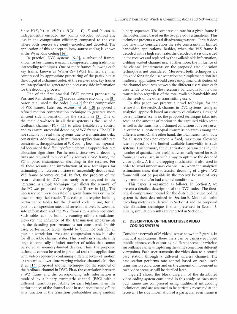
However, in other situations, a simple encoder is desired.Distributed video coding (DVC) was introduced [7, 8] topermit low-complexity encoding for small power-limitedand memory-limited devices, such as camera-equippedmobile phones or wireless video sensors (see Figure 1), bymoving the computation burden from the encoder side todecoder’s. In such scenarios, the decoder is assumed to belocated in a base station with sufficient resources.
It is known from information theory that, given twostatistically dependent sources X and Y , each source canbe independently compressed to its entropy limit H(X) andH(Y), respectively. However, by exploiting the correlationbetween the two sources, X and Y can be jointly compressedto the joint entropy H(X ,Y). This results in a reducedtotal transmission rate since H(X ,Y) ≤ H(X) + H(Y).The idea behind DVC goes back to the 1970’s when Slepianand Wolf proved in [15] that, if Y is compressed to itsentropy limit H(Y), X can be transmitted at a rate veryclose to the conditional entropy H(X | Y), provided thatY is perfectly recovered at the receiver as side information.
2 EURASIP Journal on Wireless Communications and Networking
Since H(X ,Y) = H(Y) + H(X | Y), X and Y can beindependently encoded and jointly decoded without anyloss in the compression efficiency, compared to the casewhere both sources are jointly encoded and decoded. Theapplication of this concept to lossy source coding is knownas the Wyner-Ziv coding [16].
In practical DVC systems [6–9], a subset of frames,known as key frames, is usually compressed using traditionalintracoding techniques. One or more frames following eachkey frame, known as Wyner-Ziv (WZ) frames, are thencompressed by appropriate puncturing of the parity bits atthe output of a channel coder. At the receiver side, key framesare interpolated to generate the necessary side informationfor the decoding process.
One of the first practical DVC systems proposed byPuri and Ramchandran [7] used syndrome encoding. In [8],Aaron et al. used turbo codes [17–19] for the compressionof WZ frames. Later on, Ascenso et al. [10] proposed arefined motion compensation technique to generate moreefficient side information for the system in [8]. One ofthe main drawbacks in all these systems is the use of afeedback channel (FC) [11] to allow flexible rate controland to ensure successful decoding of WZ frames. The FC isnot suitable for real-time systems due to transmission delayconstraints. Additionally, in multiuser applications with rateconstraints, the application of WZ coding becomes impracti-cal because of the difficulty of implementing appropriate rateallocation algorithms. Furthermore, since several decodingruns are required to successfully recover a WZ frame, theFC imposes instantaneous decoding in the receiver. Forall these reasons, the introduction of new techniques forestimating the necessary bitrate to successfully decode eachWZ frame becomes crucial. In fact, the problem of thereturn channel in DVC has rarely been targeted in theliterature. A simple technique that allows the removal ofthe FC was proposed by Artigas and Torres in [12]. Thenecessary compression rate of a given frame was estimatedbased on empirical results. This estimation requires buildingperformance tables for the channel code in use, for allpossible compression rates and correlation levels between theside information and the WZ frames in a given sequence.Such tables can be built by running offline simulations.However, the influence of the transmission impairmentson the decoding performance is not considered. In thiscase, performance tables should be built not only for allpossible correlation levels and compression rates, but alsofor all possible channel states. This results in a significantlylarge (theoretically infinite) number of tables that cannotbe stored in memory-limited devices. Thus, the proposedtechnique cannot be used in practical real-time applicationswith video sequences containing different levels of motionor transmitted over time-varying wireless channels. Morbeeet al. [13] proposed another technique for the removal ofthe feedback channel in DVC. First, the correlation betweena WZ frame and the corresponding side information ismodeled by a binary symmetric channel (BSC) with adifferent transition probability for each bitplane. Then, theperformances of the channel code in use are estimated offlineas a function of the transition probabilities using random
binary sequences. The compression rate for a given frame isthen determined based on the two previous estimations. Thistechnique presents several disadvantages as well. First, it doesnot take into consideration the rate constraints in limitedbandwidth applications. Besides, when the WZ frame isdecoded with a high error rate, the decoded data is discardedin the receiver and replaced by the available side information,yielding wasted channel use. Furthermore, the influence ofthe channel impairments on the proposed rate allocationtechnique is not considered. Moreover, both techniques aredesigned for a single-user scenario; their implementation in amultiuser application would cause unoptimal distribution ofthe channel resources between the different users since eachuser tends to occupy the necessary bandwidth for its owntransmission regardless of the total available bandwidth andof the needs of the other transmitting users.
In this paper, we present a novel technique for theremoval of the feedback channel in DVC systems, using ananalytical approach based on entropy calculations. Designedfor a multiuser scenario, the proposed technique takes intoaccount the amount of motion in the captured video sceneas well as the transmission channel conditions for every user,in order to allocate unequal transmission rates among thedifferent users. On the other hand, the total transmission ratefor all users does not exceed a fixed, maximum allowablerate imposed by the limited available bandwidth in suchsystems. Furthermore, the quantization parameter (i.e., thenumber of quantization levels) is dynamically varied for eachframe, at every user, in such a way to optimize the decodedvideo quality. A frame dropping mechanism is also used inorder to avoid unnecessary channel use, when the analyticalestimations show that successful decoding of a given WZframe will not be possible in the receiver because of veryhigh-motion and/or bad channel conditions.
This paper is organized as follows. In Section 2, wepresent a detailed description of the DVC codec. The theo-retical compression bound for the distributed video codingsystem is then determined in Section 3. Modified turbodecoding metrics are derived in Section 4 and the proposedrate allocation technique is then presented in Section 5.Finally, simulation results are reported in Section 6.
2. DESCRIPTION OF THE MULTIUSER VIDEOCODING SYSTEM
Consider a network of N video users as shown in Figure 1. Inpractical applications, these users can be camera-equippedmobile phones, each capturing a different scene, or wirelesssurveillance cameras capturing the same scene from differentviewpoints. Each user transmits the video data to a centralbase station through a different wireless channel. Thebase station performs rate control based on each user’stransmission conditions and on the amount of movement ineach video scene, as will be detailed later.
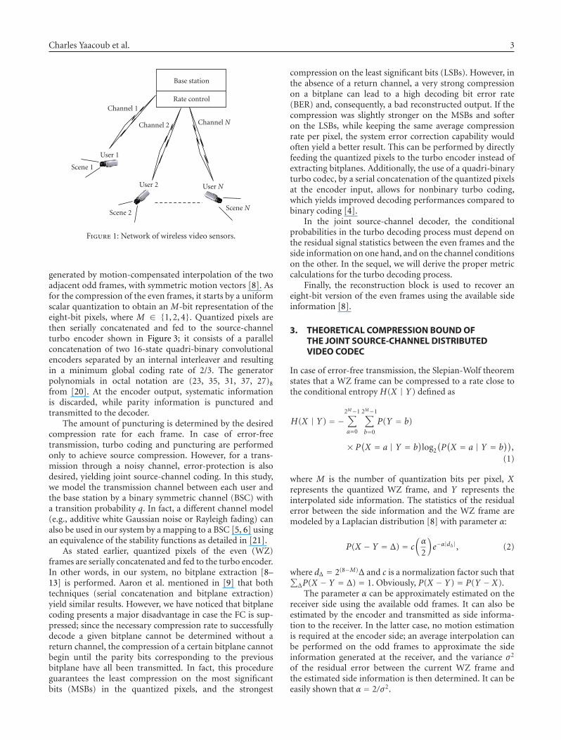
Figure 2 shows the block diagram of the distributedvideo coding system considered in this study. At each user,odd frames are compressed using traditional intracodingtechniques, and are assumed to be perfectly recovered at thereceiver. The side information of a particular even frame is
Charles Yaacoub et al. 3
Base station
Rate controlChannel 1
Channel 2 Channel N
User 1
User 2 User N
Scene 1
Scene 2Scene N
Figure 1: Network of wireless video sensors.
generated by motion-compensated interpolation of the twoadjacent odd frames, with symmetric motion vectors [8]. Asfor the compression of the even frames, it starts by a uniformscalar quantization to obtain an M-bit representation of theeight-bit pixels, where M ∈ {1, 2, 4}. Quantized pixels arethen serially concatenated and fed to the source-channelturbo encoder shown in Figure 3; it consists of a parallelconcatenation of two 16-state quadri-binary convolutionalencoders separated by an internal interleaver and resultingin a minimum global coding rate of 2/3. The generatorpolynomials in octal notation are (23, 35, 31, 37, 27)8
from [20]. At the encoder output, systematic informationis discarded, while parity information is punctured andtransmitted to the decoder.
The amount of puncturing is determined by the desiredcompression rate for each frame. In case of error-freetransmission, turbo coding and puncturing are performedonly to achieve source compression. However, for a trans-mission through a noisy channel, error-protection is alsodesired, yielding joint source-channel coding. In this study,we model the transmission channel between each user andthe base station by a binary symmetric channel (BSC) witha transition probability q. In fact, a different channel model(e.g., additive white Gaussian noise or Rayleigh fading) canalso be used in our system by a mapping to a BSC [5, 6] usingan equivalence of the stability functions as detailed in [21].
As stated earlier, quantized pixels of the even (WZ)frames are serially concatenated and fed to the turbo encoder.In other words, in our system, no bitplane extraction [8–13] is performed. Aaron et al. mentioned in [9] that bothtechniques (serial concatenation and bitplane extraction)yield similar results. However, we have noticed that bitplanecoding presents a major disadvantage in case the FC is sup-pressed; since the necessary compression rate to successfullydecode a given bitplane cannot be determined without areturn channel, the compression of a certain bitplane cannotbegin until the parity bits corresponding to the previousbitplane have all been transmitted. In fact, this procedureguarantees the least compression on the most significantbits (MSBs) in the quantized pixels, and the strongest
compression on the least significant bits (LSBs). However, inthe absence of a return channel, a very strong compressionon a bitplane can lead to a high decoding bit error rate(BER) and, consequently, a bad reconstructed output. If thecompression was slightly stronger on the MSBs and softeron the LSBs, while keeping the same average compressionrate per pixel, the system error correction capability wouldoften yield a better result. This can be performed by directlyfeeding the quantized pixels to the turbo encoder instead ofextracting bitplanes. Additionally, the use of a quadri-binaryturbo codec, by a serial concatenation of the quantized pixelsat the encoder input, allows for nonbinary turbo coding,which yields improved decoding performances compared tobinary coding [4].
In the joint source-channel decoder, the conditionalprobabilities in the turbo decoding process must depend onthe residual signal statistics between the even frames and theside information on one hand, and on the channel conditionson the other. In the sequel, we will derive the proper metriccalculations for the turbo decoding process.
Finally, the reconstruction block is used to recover aneight-bit version of the even frames using the available sideinformation [8].
3. THEORETICAL COMPRESSION BOUND OFTHE JOINT SOURCE-CHANNEL DISTRIBUTEDVIDEO CODEC
In case of error-free transmission, the Slepian-Wolf theoremstates that a WZ frame can be compressed to a rate close tothe conditional entropy H(X | Y) defined as
H(X | Y) = −2M−1∑
a=0
2M−1∑
b=0
P(Y = b)
× P(X = a | Y = b)log2
(P(X = a | Y = b
)),
(1)
where M is the number of quantization bits per pixel, Xrepresents the quantized WZ frame, and Y represents theinterpolated side information. The statistics of the residualerror between the side information and the WZ frame aremodeled by a Laplacian distribution [8] with parameter α:
P(X − Y = Δ) = c(α
2
)e−α|dΔ|, (2)
where dΔ = 2(8−M)Δ and c is a normalization factor such that∑ΔP(X − Y = Δ) = 1. Obviously, P(X − Y) = P(Y − X).
The parameter α can be approximately estimated on thereceiver side using the available odd frames. It can also beestimated by the encoder and transmitted as side informa-tion to the receiver. In the latter case, no motion estimationis required at the encoder side; an average interpolation canbe performed on the odd frames to approximate the sideinformation generated at the receiver, and the variance σ2
of the residual error between the current WZ frame andthe estimated side information is then determined. It can beeasily shown that α = 2/σ2.
4 EURASIP Journal on Wireless Communications and Networking
Videosequence
Even frames
Odd frames
Quantization
Intra-coding
Intraframeencoder
Interframedecoder
Slepian-Wolf codec
Joint source-channel encoder BSC
Joint source-channel decoder
Reconstruction
Interpolation
Quantization
Intra-decoding
Videosequence
Figure 2: Block diagram of the pixel-domain distributed video coding system.
{xsik}
i = 1, 2, 3, 4
Internalinterleaver
Quadri-binaryencoder #1
Quadri-binaryencoder #2
{xsik}
i = 1, 2, 3, 4
Systematicinformation
xp1k
Encoder #1parity bit
xp2k
Encoder #2parity bit
Figure 3: Quadri-binary turbo encoder.
On the other hand,
P(X − Y = Δ) =∑
b
P(X = a = Δ + b | Y = b)P(Y = b).
(3)
The number of nonzero terms in (3) is equal to the numberLda−b of couples (a, b) that yield the residual differenceΔ = a − b. Supposing an equiprobable source, thesecouples can be considered to be equally likely; for example,considering a two-bit quantization, the possible values ofΔ are 0, ±1, ±2, and ±3 (i.e., dΔ = 0,±64,±128, and ±192),with a decreasing order of probability of occurrence. Fora particular value of the difference Δ, couples (a, b) thatyield the difference Δ have the same probability to occur. Forexample, for Δ = 1, the occurrences of (a = 1, b = 0), (a = 2,b = 1), and (a = 3, b = 2) are equally likely. Therefore, wecan write
P(X = a | Y = b) = 2M
LdΔP(X − Y = Δ), (4)
where Δ = a− b. By calculating LdΔ for different values of Δ,we found that LdΔ = 2M − |dΔ|.
Besides, it can be easily shown that P(X | Y) = P(Y |X). In fact, since P(X − Y) = P(Y − X) (from (2)), |dΔ| =|2(8−M)Δ| = |2(8−M)(−Δ)| = |d−Δ|, and LdΔ = 2M − |dΔ| =
Ld−Δ , we have
P(Y = b | X = a) = 2M
Ldb−aP(Y − X = b − a)
= 2M
Lda−bP(X − Y = a− b)
= P(X = a | Y = b).
(5)
Finally, combining (1), (2), and (4) yields
H(X | Y)
= −2M−1∑
a=0
2M−1∑
b=0
cα
2e−α|da−b|
Lda−blog2
(c
2M−1αe−α|da−b|
Lda−b
).
(6)
Let Hf (M) be the theoretical lower compression bound for avideo frame f transmitted in the absence of noise, expressedas in (6). Since the transmission channel between a userand the base station is modeled by a BSC with a transitionprobability q, the overall theoretical compression boundbecomes [1]
H′f (M) = Hf (M)
C(q), (7)
where C(q) is the capacity of the BSC defined as
C(q) = 1 + qlog2(q) + (1− q)log2(1− q). (8)
Charles Yaacoub et al. 5
In the presence of transmission errors, the Wyner-Ziv codecperforms joint source-channel coding. Equation (7) showsthat, by considering channel impairments, the compressionbound increases as the channel noise increases (H′
f (M) ≥Hf (M) since 0 ≤ C(q) ≤ 1). On the other hand, it can beverified that in the absence of channel errors, since no errorprotection is needed and C(q) = 1, (7) reduces to (6) asexpected.
4. JOINT SOURCE-CHANNEL TURBO DECODING
Turbo decoding is realized by iterative soft-input soft-output(SISO) decoders based on the Max-Log-MAP (maximum aposteriori) algorithm [22]. However, since nonbinary codesare used in this work, we modified the metric calculationsin order to take into account all possible transitions betweenany couple of trellis states. Moreover, the conditional prob-abilities in the turbo decoding process must rely on theresidual signal statistics between the even frames and the sideinformation on one hand, and on the channel conditions onthe other.
As for the turbo decoding algorithm, we chose theMax-Log-MAP algorithm in order to reduce the decodingcomplexity. Note that the MAP or Log-MAP [22] algorithmscould also be used. However, the gain in performance wouldbe slight compared to the important increase in the decodingcomplexity.
Let {xs1k, xs2k, xs3k, xs4k} be a group of four systematic bitsat the input of the turbo encoder at time instant k, and{xp1k, x
p2k} the corresponding output parity bits from the
first and second encoders, respectively (see Figure 3). Let{yp1k, y
p2k} be the received noisy versions of the parity bits at
the output of the BSC with transition probability q. Sinceonly parity bits are transmitted by the Slepian-Wolf encoder,the decoder replaces the missing systematic bits with theircorresponding side information {ys1k, ys2k, ys3k, ys4k} generatedusing the key (i.e., odd) frames.
During the turbo decoding process, each constituentconvolutional decoder needs to determine the conditionalprobability:
P(yk | xk
) = P(ysk | xsk
)P(ypk | xpk
)
= P(ys1k, ys2k, ys3k, ys4k | xs1k, xs2k, xs3k, xs4k
)
× P(ypik | xpik),
(9)
where yk = {ysk, ypik} and ysk = {ys1k, ys2k, ys3k, ys4k}. Similarly,
xk = {xsk, xpik} and xsk = {xs1k, xs2k, xs3k, xs4k}. The index i
represents the order of the constituent encoder, i = 1 or 2.In the case where the quantization parameter M = 4, the
four systematic bits at the turbo decoder input correspond toone quantized pixel from the interpolated frame.
Let X = 8xs1k + 4xs2k + 2xs3k + xs4k be the bin index of thequantized pixel in the WZ frame, and Y = 8ys1k + 4ys2k +
2ys3k + ys4k the bin index of the corresponding quantized sideinformation. Using (4), we can write
P(ys1k, ys2k, ys3k, ys4k | xs1k, xs2k, xs3k, xs4k
) = P(Y | X)
= 2M
LdY−XP(Y − X),
(10)
where P(Y − X) is defined in (2) and LdY−X is the number ofcouples (X ,Y) that yield the residual difference Δ = Y − X .
In the case where M = 2, the four systematic bitscorrespond to two quantized pixels.
Let X1 = 2xs1k + xs2k and X2 = 2xs3k + xs4k be the bins ofthe two WZ quantized pixels with their corresponding sideinformation Y1 = 2ys1k + ys2k and Y2 = 2ys3k + ys4k. Therefore,
P(ys1k, ys2k, ys3k, ys4k | xs1k, xs2k, xs3k, xs4k
)
= P(Y1 | X1
)P(Y2 | X2
)
= 22M
LdY1−X1LdY2−X2
P(Y1 − X1
)P(Y2 − X2
).
(11)
When M = 1, each systematic bit corresponds to one pixel.Let Xi = xsik be the bin index of the quantized pixel i (i =1, . . . , 4), and Yi = ysik the corresponding side information:
P(ys1k, ys2k, ys3k, ys4k | xs1k, xs2k, xs3k, xs4k
)
=4∏
i=1
P(Yi | Xi
) 4∏
i=1
2M
LdYi−XiP(Yi − Xi
).
(12)
Now, as P(ysk | xsk) has been determined for all possible valuesof M, we can proceed with the calculation of P(y
pk | xpk ) in
(9).First, let Ppunct(ρ) be the probability of puncturing a
parity bit expressed as a function of the compression rateρ for the current WZ frame. ρ is defined as the ratio of thenumber Np of remaining parity bits after puncturing overthe total number of systematic bits Ns. Since the numberof parity bits at the turbo encoder output is Ns/2 beforepuncturing, we get
Ppunct(ρ) =(Ns/2
)−Np
Ns/2= 1− 2ρ. (13)
Two cases have to be considered for the calculation of P(ypk |
xpk ) at the decoder.
Case 1. xpk has been punctured at the output of the turbo
encoder. In this case, ypk has no value (y
pk = n). Therefore,
P(ypk | xpk , x
pk is punctured
) =⎧⎨⎩
1 if ypk = n,
0 if ypk /=n.
(14)
6 EURASIP Journal on Wireless Communications and Networking
Case 2. xpk has not been punctured at the output of the turbo
encoder. In this case, ypk can take two possible values: 0 or 1.
Therefore,
P(ypk | xpk , x
pk is not punctured
)
=
⎧⎪⎪⎪⎨⎪⎪⎪⎩
0 if ypk = n,
⎧⎨⎩q if y
pk /= xpk ,
1− q if ypk = x
pk ,
if ypk = 0 or 1,
=⎧⎨⎩
0 if ypk = n,
q[1−δ(ypk−xpk
)]+(1−q)δ
(ypk−xpk
)if y
pk = 0 or 1,
(15)
where
δ(k) =⎧⎨⎩
1 if k = 0,
0 otherwise.(16)
On the other hand,
P(ypk | xpk
)
= P(ypk | xpk , x
pk is punctured
)P(xpk is punctured
)
+ P(ypk | xpk , x
pk is not punctured
)
× P(xpk is not punctured).
(17)
Thus, P(ypk | xpk ) will be calculated by
P(ypk = 0, 1 | xpk
)
= P(ypk = 0, 1 | xpk , x
pk is not punctured
)
× P(xpk is not punctured)
=P(ypk =0, 1 | xpk , xpk is not punctured
)·(1−Ppunct(ρ))
= (q[1− δ(ypk − xpk)]
+ (1− q)δ(ypk − xpk
))·2ρ,
P(ypk = n | xpk
)
= P(ypk = n | xpk , x
pk is punctured
)P(xpk is punctured
)
= P(ypk = n | xpk , x
pk is punctured
)·Ppunct(ρ) = 1− 2ρ.(18)
On the other hand, the extrinsic information on a symboldk = xsk is given by
Li(dk) = ln
P(dk = i
)
P(dk = 0
) , i = 1, 2, 3, . . . , 15. (19)
Therefore, it is easy to prove that [23]
lnP(dk=0
)= − maxi=1,...,15
{0,Li
(dk)}
,
lnP(dk= i
)=Li(dk)− max
i=1,...,15
{0,Li
(dk)}
, i=1, 2, 3, . . . , 15.
(20)
On the other side, the logarithmic branch metric from states to state s′, in the code trellis at time k, can be calculated by
γk(s′, s) = lnP
(dk)
+ lnP(ysk | dk
)+ lnP
(ypk | xpk
). (21)
As for the forward and backward state metrics, they are givenby
αk(s) = maxs′
[γk(s′, s)
+ αk−1(s′)]
,
βk−1
(s′) = max
s[γk(s′, s)
+ βk(s)].(22)
On the other hand, the log-likelihood ratio of symbol dk iscalculated using
LLRi(dk)
i=1,2,...,15= max
(s′,s)dk=i
[γk(s′, s)
+ αk−1(s′)
+ βk(s)]
−max(s′,s)dk=0
[γk(s′, s)
+ αk−1(s′)
+ βk(s)].
(23)
Finally, the extrinsic information used as a priori informa-tion to the next decoder is calculated by
Lai(dk) = LLRi
(dk)− Li
(dk)− Lci
(dk), (24)
where Lci (dk) = ln(P(ysk | dk = i)/P(ysk | dk = 0)) is ameasure of the channel reliability [18].
At the end of each decoding iteration, 15 LLRs arecalculated for each symbol dk . At the last iteration, dk isdecoded as
dk =⎧⎪⎨⎪⎩
argi
max LLRi(dk)
if maxi
LLRi(dk)> 0,
0 otherwise.(25)
5. ADAPTIVE RATE ALLOCATION ANDQUANTIZATION TECHNIQUE
Consider a system of N users sharing the same wirelessmedium to transmit video data to a base station at a totalbitrate of R bits per second (bps). Let ρ f ,n be the compressionrate for frame f at node n defined as in Section 4, Mf ,n thequantization parameter for this frame, and Af ,n =Mf ,n·ρ f ,n
its average number of bits per pixel. In our joint source-channel codec, if no parity bits are transmitted, ρ f ,n = 0. Onthe other side, if all parity bits are transmitted without anypuncturing, ρ f ,n = 1/2. As a result, the compression rate canbe varied between these two extreme cases: 0 ≤ ρ f ,n ≤ 1/2.Our aim is to determine, for each frame f at every user n,the couple (Mf ,n, ρ f ,n) that optimizes the average systemperformance. In other words,
{(Mf ,n, ρ f ,n
); n = 1, . . . ,N
} = arg maxMf ,n∈{1,2,4}0≤ρ f ,n≤1/2
(1N
N∑
n=1
PSNR f ,n
),
(26)
where PSNR f ,n is the peak signal-to-noise ratio obtainedafter the decoding and reconstruction of the frame f

Charles Yaacoub et al. 7
encoded at the user n. PSNR f ,n depends not only on theparameters Mf ,n and ρ f ,n, but also on the transmissionconditions, the accuracy of the side information, and the rateconstraint:
N∑
n=1
Rf ,n ≤ R, (27)
where Rf ,n is the transmission rate assigned for the frame fat the user n. As a result, it is difficult to solve analytically(26) for the set {(Mf ,n, ρ f ,n); n = 1, . . . ,N}. For this reason,we proceed with the optimization process in two stages.First, we determine the transmission rate for each user, andthen we choose the couples (Mf ,n, ρ f ,n) that yield the bestreconstructed output at the specified bitrates.
In the first stage, instead of assigning R/N bps for eachuser, the base station first determines the compression boundfor each frame as in (7), based on its content (parameter α)and on the user transmission conditions (channel crossoverprobability q). Since the optimal quantization parameterhas not been determined yet, (7) is calculated for M = 8,assuming eight-bit raw video data before compression. Then,in a proportionally fair attribution, the user n is assigned therate
Rf ,n =H′
f ,n(8)∑N
n=1H′f ,n(8)
R, (28)
where H′f ,n(8) represents the entropy in (7) calculated for
frame f at node n with M = 8.The average number of bits per pixel Af ,n is related to
Rf ,n by
Af ,n =Rf ,n
m·n·r , (29)
where (m,n) represent the dimensions of a given frame, andr the WZ frame rate (in fps).
In the second stage, the base station needs to determine,for each frame f at every node n, the couple (Mf ,n, ρ f ,n)that yields the best video output after reconstruction, at thespecified rate Rf ,n. In fact, this is equivalent to optimizing theindividual rate-distortion performance for each user since,for a given bitrate, the parameters are chosen in such a wayto maximize PSNR f ,n.
After a thorough analysis of the system performanceobserved for different values ofMf ,n, we noticed that in mostcases, for a given target bitrate, choosing the lowest allowablevalue of Mf ,n yields the best video quality at the decoderoutput. Indeed, by reducing the number of quantizationlevels, the system is able to transmit a greater amount ofparity bits to protect the quantized bitstream from channelerrors, especially when q increases. However, in some cases,the assigned bitrate is sufficient enough to permit efficienterror protection when a greater value of Mf ,n is selected;thus, a better reconstructed output can be obtained. Inall cases, we noticed that the system behavior for differentconfigurations of the couples (Mf ,n, ρ f ,n) is directly related
to the ratio between Af ,n and the theoretical compressionbound defined as
Cf ,n(Mf ,n
) = Af ,n
H′f ,n
(Mf ,n
) . (30)
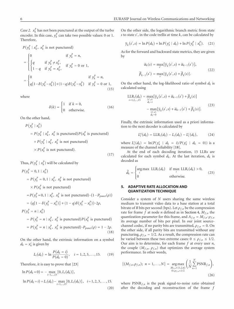
Therefore, we define the thresholds T1, T2, and T4 whichindicate the average value of the ratioCf ,n(Mf ,n) that permitsa correct decoding of a transmitted frame for Mf ,n =1, 2, and 4, respectively. These thresholds are determinedexperimentally by observing the system performance fordifferent values of the ratio Cf ,n(Mf ,n), as will be detailed inSection 6. Our proposed algorithm then proceeds with thedynamic quantization (see Figure 4) as follows.
Step 1. Initially, set Mf ,n to the lowest value that permits toreach Af ,n. This will allow for the maximum error protectionfor a given Af ,n.
Step 2. Calculate Cf ,n(1), Cf ,n(2), and Cf ,n(4).
Step 3. If M = 4 and Cf ,n(4) ≤ T4, set Mf ,n = 2 andρ f ,n = 1/2. In other words, if Af ,n could not be reachedfor Mf ,n < 4 (i.e., Af ,n > 1) and the amount of errorprotection transmitted with Mf ,n = 4 does not yield anacceptable decoding error rate, set Mf ,n to the next lowervalue and transmit all parity bits. In this case, the given frameis transmitted at a rate lower than the target bitrate since thetargetAf ,n could not be reached exactly. Similarly, ifMf ,n = 2and Cf ,n(2) ≤ T2, set Mf ,n = 1 and ρ f ,n = 1/2.
Step 4. If Mf ,n = 1 and Cf ,n(1) ≤ T1, drop the frame (setMf ,n = 0). In this case, the amount of transmitted bits willnot permit efficient decoding even if the number of quan-tization levels is reduced to its minimum. At the decoder,the dropped frame is replaced by the corresponding sideinformation. Note that other error concealment techniquescan also be envisaged in the receiver.
Step 5. If Mf ,n = 1 and Cf ,n(2) > T2, set Mf ,n = 2. In otherwords, if Af ,n is reachable with Mf ,n = 1 and 2, and it ispossible to send a sufficient amount of parity bits to correctlydecode the frame with Mf ,n = 2, set Mf ,n = 2 since it yieldsa better reconstructed output. Similarly, if Mf ,n = 2 andCf ,n(4) > T4, set Mf ,n = 4.
Step 6. If the frame was not dropped and ρ f ,n was not alreadyset to 1/2, set ρ f ,n = Af ,n/Mf ,n.
Step 7. Transmit the couple (Mf ,n, ρ f ,n) to the correspondinguser.
As it can be seen from the proposed algorithm, controlinformation is sent only once from the base station to theusers. Moreover, instantaneous decoding at the receiver isno more required, and only one decoding run is performedfor each frame. As a result, all the disadvantages related tothe return channel in traditional Wyner-Ziv applications areeliminated.
8 EURASIP Journal on Wireless Communications and Networking
Af ,n =Rf ,n
m · n · r
A f ,n ≤ 0.5No Af ,n ≤ 1 No
Yes
Set Mf ,n = 1
Yes
Set Mf ,n = 2 Set Mf ,n = 4
Cf ,n(Mf ,n) = Af ,n
H′f ,n(Mf ,n)
Mf ,n = 4,
Cf ,n(4) ≤ T4
No
Yes
Set Mf ,n = 2,
ρ f ,n = 1/2
Mf ,n = 2,
Cf ,n(2) ≤ T2
No
Yes
Set Mf ,n = 1,
ρ f ,n = 1/2
Mf ,n = 1,
Cf ,n(1) ≤ T1
No Mf ,n = 1,
Cf ,n(2) > T2
No
Yes
Drop the frame
Yes
Set Mf ,n = 2
Mf ,n = 2,
Cf ,n(4) > T4
No
Yes
Set Mf ,n = 4
ρ f ,n = 1/2 No
Yes ρ f ,n =Af ,n
Mf ,n
End the dynamic quantization process
Figure 4: Dynamic quantization algorithm with a frame droppingmechanism.
17001200700200
Total bitrate R (kbps)
TRD, M = 1TRD, M = 2TRD, M = 4
ARA, M = 1ARA, M = 2ARA, M = 4
36
37
38
39
40
41
Ave
rage
PSN
R(d
B)
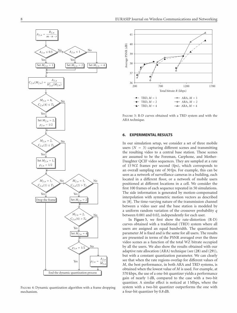
Figure 5: R-D curves obtained with a TRD system and with theARA technique.
6. EXPERIMENTAL RESULTS
In our simulation setup, we consider a set of three mobileusers (N = 3) capturing different scenes and transmittingthe resulting video to a central base station. These scenesare assumed to be the Foreman, Carphone, and Mother-Daughter QCIF video sequences. They are sampled at a rateof 15 WZ frames per second (fps), which corresponds toan overall sampling rate of 30 fps. For example, this can beseen as a network of surveillance cameras in a building, eachlocated in a different floor, or a network of mobile userspositioned at different locations in a cell. We consider thefirst 100 frames of each sequence repeated in 50 simulations.The side information is generated by motion-compensatedinterpolation with symmetric motion vectors as describedin [8]. The time-varying nature of the transmission channelbetween a video user and the base station is modeled bya uniform random variation of the crossover probability qbetween 0.001 and 0.02, independently for each user.
In Figure 5, we first show the rate-distortion (R-D)curves obtained with a traditional (TRD) system where allusers are assigned an equal bandwidth. The quantizationparameter M is fixed and is the same for all users. The resultsare presented in terms of the PSNR averaged over the threevideo scenes as a function of the total WZ bitrate occupiedby all the users. We also show the results obtained with ouradaptive rate allocation (ARA) technique (see (28) and (29)),but with a constant quantization parameter. We can clearlysee that when the rate regions overlap for different values ofM, the best performance, in both ARA and TRD systems, isobtained when the lowest value of M is used. For example, at570 kbps, the use of a one-bit quantizer yields a performancegain of nearly 1 dB, compared to the case with a two-bitquantizer. A similar effect is noticed at 1 Mbps, where thesystem with a two-bit quantizer outperforms the one witha four-bit quantizer by 0.8 dB.

Charles Yaacoub et al. 9
1700150013001100900
Total bitrate R (kbps)
TRD (D)ARA (D)ARA (F)
ARA (C)TRD (F)TRD (C)
33
35
37
39
41
43
45
Ave
rage
PSN
R(d
B)
Figure 6: Individual PSNR as a function of the total bitrate, for theCarphone (C), Foreman (F), and Mother-Dauther (D) sequences,with M = 4.
In some cases, the performance of a TRD system canbe better than that of ARA. In Figure 6, we present theindividual PSNR of the different video sequences, for thecase where M = 4. In fact, a similar behavior is observedfor different values of M. We notice that at a total bitrate of1 Mbps, the performance loss for the Mother-Daughter (D)sequence is relatively high, which degrades the average ARAsystem performance, compared to the TRD system, as alsoshown in Figure 5. The remedy for this problem is to reducethe number of quantization levels for the transmission atthis bitrate, as was explained earlier. We also notice thatthe ARA technique significantly improves the PSNR of theCarphone (C) and Foreman (F) sequences at the expenseof a reduced performance for Mother-Daughter. This canbe explained by the fact that the Mother-Daughter sequencecontains low-motion scenes, while Carphone and Foremanare characterized by average and high-motion scenes. In fact,the ARA technique allocates the lowest rates for videos withlow motion and/or experiencing good channel conditions,while the highest rates are assigned to video users capturinghigh-motion scenes and/or suffering from a bad channel.This results in an improved average system performance,especially at medium and high total transmission rates.
The analysis of the individual PSNR as a function of thetotal bitrate (as in Figure 6) can sometimes be misleading.In Figure 7, the PSNR of each video sequence is representedas a function of the effective WZ bitrate assigned for eachuser, for the case where M = 4. Figure 7 clearly showsthat the R-D curves obtained with the ARA technique areabove those obtained with a TRD system. This implies thatthe ARA technique improves not only the average systemperformance, but the individual R-D performance for eachuser as well, especially at medium and high bitrates.
This effect can be further explained by Table 1 whichshows the average bitrates (in kbps) assigned for each userwith the ARA technique. In the TRD system, all users operate
700600500400300200
Individual bitrate R (kbps)
ARA (D)TRD (D)ARA (F)
TRD (F)ARA (C)TRD (C)
33
35
37
39
41
43
45
Ave
rage
PSN
R(d
B)
Figure 7: Individual R-D curves for the Carphone (C), Foreman(F), and Mother-Dauther (D) sequences obtained with M = 4.
at the same bitrate. Indeed, we notice that in all cases, for acertain total bitrate, the ARA technique assigns the Mother-Daughter sequence the lowest bitrate compared to the twoother sequences. For example, at a total rate of 1.5 Mbps,the bitrate assigned for Mother-Daughter is almost half theone assigned for Carphone. Moreover, the bitrate assignedfor the Mother-Daughter sequence by the ARA technique isless than the one assigned by the TRD system. This allows theassignment of higher bitrates to the two other sequences, andleads to an improvement in the overall system performance.
In order to apply the dynamic quantization algorithmand the frame dropping mechanism, it is necessary todetermine suitable values for the thresholds T1, T2, andT4 defined in Section 5. For this purpose, we show, inFigure 8, the BER obtained after source-channel decoding,as a function of the ratio Cf ,n defined in (30). For each valueof M, the transmission of 22500 frames from different videosequences was simulated with variable channel conditions.In general, a BER close to 10−3 is desired to yield agood reconstructed output [8]. When M = 1, only themost significant bit in each pixel is coded and transmitted,which greatly affects the performance of the reconstructionfunction. For this reason, we chose a threshold T1 = 6 toguarantee a BER less than 10−3 in this case. Similarly, wechose T2 = 4 for a BER of 10−3 when M = 2. For the casewhere M = 4, a higher BER can be tolerated since the twoleast significant bits in the quantized pixel are less importantthan the two most significant bits. Therefore, we chose T4 =2.4. In the sequel, we will show the system performances forthese selected values of the thresholds, and compare them tothe ones obtained with other values of T2 and T4.
In Figure 9, it can be seen that the problem of overlappingrate regions is avoided by applying dynamic quantiza-tion (curves labeled “ARAQ” and “ARAQ-D”), in additionto adaptive rate allocation. When no frame dropping isperformed (ARAQ: Step 4 in the dynamic quantization

10 EURASIP Journal on Wireless Communications and Networking
Table 1: Average individual bitrates in kbps for the Carphone (C), Foreman (F), and Mother-Dauther (D) sequences.
Total TRD ARA (C) ARA (F) ARA (D)
M = 1249.5 83.16 80.1 95.5 73.9
320.8 106.92 103.2 124.4 93.2
392 130.68 127.6 150.5 113.9
M = 2499 166.32 212.9 168.3 117.7
641.5 213.84 274.2 219.9 147.4
784.1 261.36 331.1 274.4 178.6
M = 4997.9 332.64 405.4 353.4 239.2
1283 427.68 520.3 461.9 300.8
1568.2 522.72 636.5 568.5 363.1
97531
Ratio
M = 1M = 2
M = 4
1E − 06
1E − 05
1E − 04
1E − 03
1E − 02
1E − 01
1E + 00
BE
R
Figure 8: Performance curves showing the BER as a function of theratio in (30) for M = 1, 2, and 4.
algorithm is skipped), a performance gain towards the TRDsystem is observed only at high rates, for T2 = T4 = 2.7.The reason for this behavior is that, at low rates, M takesthe values 1 or 2 most of the time and T2 = 2.7 does notguarantee a good BER when M = 2, as shown in Figure 8,whereas for M = 4 (mostly at high rates), T4 = 2.7 yieldsacceptable performance. Compared to the TRD system, veryclose performances are obtained at low rates by setting T2 =4 and T4 = 2.4, while an important enhancement is noticedat medium and high rates. In fact, at very low rates, theavailable bandwidth to be allocated for the different usersis barely sufficient to protect the transmitted bitstreams.At a rate near 200 kbps, we notice a performance loss of0.5 dB, whereas a gain of 1.5 dB is observed with the framedropping mechanism (ARAQ-D curves) for T1 = 6. Whenthe bitrate increases, less frames are dropped. Starting from600 kbps, the R-D curves are the same with or without framedropping. This is expected since frames are only droppedwhen the assigned bitrate is not sufficient to guarantee acorrect decoding of the transmitted WZ frame. On the otherhand, at 500 kbps, our proposed algorithm yields similarperformance compared to the TRD system with M = 1, but
170014501200950700450200
Total bitrate R (kbps)
TRD, M = 1TRD, M = 2TRD, M = 4
ARAQ: T2 = T4 = 2.7ARAQ: T2 = 4,T4 = 2.4ARAQ-D: T1 = 6,T2 = 4,T4 = 2.4
ARA, M = 1ARA, M = 2ARA, M = 4
36
37
38
39
40
41
Ave
rage
PSN
R(d
B)
Figure 9: R-D Curves obtained with a TRD system and with theARAQ and ARAQ-D techniques.
a gain of 1.4 dB is observed towards the case where M = 2.At 1 Mbps, the gain reaches 0.6 dB compared to M = 2 and1.5 dB to M = 4.
It is important to note that when M is fixed (TRD andARA systems), the transmission bitrate for the WZ codecis limited to a narrow range. For example, a traditionalsystem with N = 3 cannot transmit at a total rate greaterthan 570 kbps when M = 1, and 1140 kbps when M = 2(assuming QCIF video sequences sampled at 15 WZ-fps).Our proposed algorithm with the ARAQ and ARAQ-Dtechniques allows the system to transmit video data at a widerrange of transmission rates and with an optimized decodingquality.
Figures 10, 11, and 12 show the individual R-D perfor-mance for the Carphone (C), Foreman (F), and Mother-Daughter (D) sequences, respectively, obtained with ourARAQ-D technique with T1 = 6, T2 = 4, and T4 = 2.4.Compared to the TRD system, it can be seen, as explainedin Section 5, that the R-D performance for each user isimproved, especially at high rates. At an individual rate of430 kbps, the gain reaches 1.5 dB for Carphone, 1.2 dB forForeman, and 0.6 dB for Mother-Daughter. Again, it can beseen that Mother-Daughter is assigned the lowest bitrates.The maximum bitrate allocated to the Mother-Daughtersequence is 430 kbps, while Carphone and Foreman are

Charles Yaacoub et al. 11
64044024040
Bitrate R (kbps)
ARAQ-D (C)TRD (C) M = 1
TRD (C) M = 2TRD (C) M = 4
32
33
34
35
36
37
38
39
40
PSN
R(d
B)
Figure 10: R-D curves for the Carphone (C) sequence obtainedwith the ARAQ-D technique, compared to the performance of aTRD system.
64044024040
Bitrate R (kbps)
ARAQ-D (F)TRD (F) M = 1
TRD (F) M = 2TRD (F) M = 4
35
36
37
38
39
40
PSN
R(d
B)
Figure 11: R-D curves for the Foreman (F) sequence obtained withthe ARAQ-D technique, compared to the performance of a TRDsystem.
assigned a maximum of 615 kbps and 610 kbps, respectively.The unequal assignment of channel resources with theproposed rate allocation techniques (ARA, ARAQ, andARAQ-D) results in an improvement in the overall systemperformance.
In our simulations, key frames were assumed to beperfectly recovered at the receiver. The case where key framesare subject to degradations due to lossy source coding orchannel impairments can be easily taken into account inour study by modifying the entropy calculations in Section 3accordingly. However, it should be noted that, in this case, allstudied systems (TRD, ARA, ARAQ, and ARAQ-D) would besubject to a similar performance degradation. As a result, theperformance analysis presented earlier would still hold.
54044034024014040
Bitrate R (kbps)
ARAQ-D (D)TRD (D) M = 1
TRD (D) M = 2TRD (D) M = 4
40
41
42
43
44
45
PSN
R(d
B)
Figure 12: R-D curves for the Mother-Daughter (D) sequenceobtained with the ARAQ-D technique, compared to the perfor-mance of a TRD system.
In Figure 13, we show a snapshot from the Carphonevideo sequence (7th WZ frame) obtained with both theTRD (Figures Figure 13(b) and Figure 13(c)) and ARAQ-D(Figures 13(d) and 13(e)) systems, for the same transmissionconditions (Rf ,n = 332.64 kbps and q = 6.4·10−3). The mid-dle column shows the turbo decoded images before recon-struction, and the right column shows the final reconstructedoutputs. In the TRD system, the quantization parameter wasset to Mf ,n = 4 and the compression rate to ρ f ,n = 0.21875,whereas the ARAQ-D system determined that Mf ,n = 2 andρ f ,n = 0.4375 would yield a better result, even though in bothcases Af ,n = 0.875. In fact, when Mf ,n = 4, more detailsabout the transmitted image are available at the receiver,as shown in Figure 13(b) compared to Figure 13(d). This issupposed to help the reconstruction function in improvingthe output video quality. However, the received frame wasdecoded with BER = 0.09 in the TRD system, giving a noise-like visual effect (see Figure 13(b)), whereas in the ARAQ-Dsystem, the frame was perfectly recovered (BER ≈ 0) withMf ,n = 2 (see Figure 13(d)). This is due to the fact that,in the latter case, the choice of ρ f ,n = 0.4375 leads to abetter protection of the transmitted bitstream. The superiorperformance of the ARAQ-D system can be observed bycomparing Figures 13(c) and 13(e). A visual inspection ofboth images shows that the reconstruction function was notable to completely remove the noise-like effect from thedecoded image in the TRD system, whereas in the ARAQ-D system, the reconstructed image is visually better. Thisperformance gain can be further observed in the outputPSNR: 31.5 dB in Figure 13(c) and 34 dB in Figure 13(e),resulting in a 2.5 dB gain. However, in both cases, the PSNRfor this frame is below the average PSNR obtained at thesame bitrate and presented in Figure 10. This is due toa higher level of motion in this particular frame, comparedto the average motion level in the sequence.
Finally, we show in Figure 14 the 40th WZ frame fromthe Foreman sequence. In the ARAQ system, the original

12 EURASIP Journal on Wireless Communications and Networking
(a) Original image (b) TRD decoded image (c) TRD reconstructed image
(d) ARAQ-D decoded image (e) ARAQ-D reconstructed image
Figure 13: Snapshot from the Carphone sequence. (a) Original image. (b) TRD turbo decoded image with M = 4 and ρ = 0.21875. (c)Reconstructed image from (b). (d) ARAQ-D turbo decoded image with M = 2 and ρ = 0.4375. (e) Reconstructed image from (d).
(a) Original image (b) ARAQ reconstructed image (c) ARAQ-D reconstructed image
Figure 14: Snapshot from the Foreman sequence. (a) Original image. (b) ARAQ reconstructed image withM = 1 and ρ = 0.25. (c) ARAQ-Doutput image obtained by replacing the frame with its corresponding side information.
WZ frame was quantized with M = 1, compressed withρ = 0.25, and transmitted at 95 kbps over a BSC with q =9·10−3. As in the previous example, the image was decodedwith a high BER (0.02) which caused undesirable noisein the reconstructed output (Figure 14(b)). The ARAQ-Dsystem determined that under these conditions, it is notpossible to recover an acceptable version of the transmittedframe. Therefore, the frame was dropped in the transmitterand replaced by the corresponding side information at thereceiver side (Figure 14(c)). It can be clearly seen that theresulting image has a smoother visual effect. The PSNR inFigure 14(b) is 30.65 dB compared to 32.61 in Figure 14(c),resulting in a 2 dB gain. However, in both images, we noticea deformation of the mouth (compared to Figure 14(a)). Infact, this frame was captured from a fast mouth openingand closing scene (high-motion of the lips), which yielded
less accurate side information for this region. In general,when the available transmission rate permits an error-freedecoding of the WZ frame, the influence of inaccurate sideinformation on the final output is reduced to a large extent.
7. CONCLUSION
In this paper, we introduced a novel rate allocation techniquefor distributed multiuser Wyner-Ziv video coding systems.Using entropy calculations, the available system bandwidth isunequally distributed among several users transmitting datato a central base station without the need for a permanentfeedback channel. The proposed rate allocation techniqueallows the system to adapt to the random variations ofthe wireless channel and to different amounts of motioncaptured by the different users. The quantization parameters

Charles Yaacoub et al. 13
are dynamically varied to optimize the decoding quality,and a frame dropping mechanism allows the system toavoid unnecessary channel use. Our results obtained bysimulating a network of multiple users show a significantimprovement in the average system performance, as well asin the individual R-D performance of each user. The gain inthe average PSNR can reach 1.5 dB compared to a traditionalsystem where the available bandwidth is equally shared by allthe users and the quantization parameters are fixed.
ACKNOWLEDGMENT
This work has been supported by a research grant from theLebanese National Council for Scientific Research (LNCSR).
REFERENCES
[1] A. Aaron and B. Girod, “Compression with side informationusing turbo codes,” in Proceedings of IEEE Data CompressionConference (DCC ’02), pp. 252–261, Snowbird, Utah, USA,April 2002.
[2] J. Garcia-Frias and Y. Zhao, “Near-Shannon/Slepian-Wolfperformance for unknown correlated sources over AWGNchannels,” IEEE Transactions on Communications, vol. 53, no.4, pp. 555–559, 2005.
[3] S. S. Pradhan and K. Ramchandran, “Distributed source cod-ing: symmetric rates and applications to sensor networks,” inProceedings of IEEE Data Compression Conference (DCC ’00),pp. 363–372, Snowbird, Utah, USA, March 2000.
[4] J. Farah, C. Yaacoub, N. Rachkidy, and F. Marx, “Binary andnon-binary turbo codes for the compression of correlatedsources transmitted through error-prone channels,” in Pro-ceedings of the 4th International Symposium on Turbo Codesand Related Topics and the 6th International ITG-Conferenceon Source and Channel Coding, Munich, Germany, April 2006.
[5] J. Farah, C. Yaacoub, F. Marx, and B. Pesquet-Popescu,“Distributed coding of video sequences transmitted througherror-prone channels,” in Proceedings of the 4th InternationalConference on Science of Electronics, Technologies of Informationand Telecommunications, Hammamet, Tunisia, March 2007.
[6] J. Farah, C. Yaacoub, F. Marx, and B. Pesquet-Popescu,“Performance analysis of a distributed video coding system—application to broadcasting over an error-prone channel,” inProceedings of the 15th European Signal Processing Conference(EUSIPCO ’07), Poznan, Poland, September 2007.
[7] R. Puri and K. Ramchandran, “PRISM: a new robust videocoding architecture based on distributed compression prin-ciples,” in Proceedings of the 40th Allerton Conference onCommunication, Control and Computing, Allerton, Ill, USA,October 2002.
[8] A. Aaron, R. Zhang, and B. Girod, “Wyner-Ziv coding ofmotion video,” in Proceedings of the Conference Record of the36th Asilomar Conference on Signals, Systems and Computers(ACSSC ’02), vol. 1, pp. 240–244, Pacific Grove, Calif, USA,November 2002.
[9] A. Aaron, S. Rane, E. Setton, and B. Girod, “Transform-domain Wyner-Ziv codec for video,” in Visual Communica-tions and Image Processing, vol. 5308 of Proceedings of SPIE,pp. 520–528, San Jose, Calif, USA, January 2004.
[10] J. Ascenso, C. Brites, and F. Pereira, “Motion compensatedrefinement for low complexity pixel based distributed video
coding,” in Proceedings of IEEE International Conference onAdvanced Video and Signal Based Surveillance (AVSS ’05), vol.2005, pp. 593–598, Como, Italy, September 2005.
[11] C. Brites, J. Ascenso, and F. Pereira, “Feedback channel inpixel domain Wyner-Ziv video coding: myths and realities,” inProceedings of the 14th European Signal Processing Conference(EUSIPCO ’06), Florence, Italy, September 2006.
[12] X. Artigas and L. Torres, “Improved signal reconstructionand return channel suppression in distributed video codingsystems,” in Proceedings of the 47th International SymposiumElectronics in Marine (Elmar ’05), pp. 53–56, Zadar, Croatia,June 2005.
[13] M. Morbee, J. Prades-Nebot, A. Pizurica, and W. Philips,“Rate allocation algorithm for pixel-domain distributed videocoding without feedback channel,” in Proceedings of IEEEInternational Conference on Acoustics, Speech and Signal Pro-cessing (ICASSP ’07), vol. 1, pp. 521–524, Honolulu, Hawaii,USA, April 2007.
[14] ITU-T and ISO/IEC JTC1, “Advanced video coding forgeneric audiovisual services,” ITU-T RecommendationH.264 – ISO/IEC 14496-10 AVC, 2003.
[15] D. Slepian and J. K. Wolf, “Noiseless coding of correlatedinformation sources,” IEEE Transactions on Information The-ory, vol. 19, no. 4, pp. 471–480, 1973.
[16] A. Wyner and J. Ziv, “The rate-distortion function forsource coding with side information at the decoder,” IEEETransactions on Information Theory, vol. 22, no. 1, pp. 1–10,1976.
[17] C. Berrou, A. Glavieux, and P. Thitimajshima, “Near Shannonlimit error-correcting coding and decoding: turbo-codes. 1,”in Proceedings of IEEE International Conference on Communi-cations (ICC ’93), vol. 2, pp. 1064–1070, Geneva, Switzerland,May 1993.
[18] B. Sklar, “A primer on turbo code concepts,” IEEE Communi-cations Magazine, vol. 35, no. 12, pp. 94–102, 1997.
[19] C. Berrou, “Turbo codes: some simple ideas for efficientcommunications,” in Proceedings of the 7th InternationalWorkshop on Digital Signal Processing Techniques for SpaceCommunications, Sesimbra, Portugal, October 2001.
[20] D. Divsalar and F. Pollara, “Multiple turbo codes,” in Pro-ceedings of the Military Communications Conference (MILCOM’95), vol. 1, pp. 279–285, San Diego, Calif, USA, November1995.
[21] S.-Y. Chung, On the construction of some capacity-approachingcoding schemes, Ph.D. thesis, Massachusetts Institute of Tech-nology, Cambridge, Mass, USA, 2000.
[22] P. Robertson, P. Hoeher, and E. Villebrun, “Optimal and sub-optimal maximum a posteriori algorithms suitable for turbodecoding,” European Transactions on Telecommunications, vol.8, no. 2, pp. 119–125, 1997.
[23] Y. Gao and M. R. Soleymani, “Triple-binary circular recursivesystematic convolutional turbo codes,” in Proceedings of the5th International Symposium on Wireless Personal MultimediaCommunications (WPMC ’02), vol. 3, pp. 951–955, Honolulu,Hawaii, USA, October 2002.

Photograph © Turisme de Barcelona / J. Trullàs
Preliminary call for papers
The 2011 European Signal Processing Conference (EUSIPCO 2011) is thenineteenth in a series of conferences promoted by the European Association forSignal Processing (EURASIP, www.eurasip.org). This year edition will take placein Barcelona, capital city of Catalonia (Spain), and will be jointly organized by theCentre Tecnològic de Telecomunicacions de Catalunya (CTTC) and theUniversitat Politècnica de Catalunya (UPC).EUSIPCO 2011 will focus on key aspects of signal processing theory and
li ti li t d b l A t f b i i ill b b d lit
Organizing Committee
Honorary ChairMiguel A. Lagunas (CTTC)
General ChairAna I. Pérez Neira (UPC)
General Vice ChairCarles Antón Haro (CTTC)
Technical Program ChairXavier Mestre (CTTC)
Technical Program Co Chairsapplications as listed below. Acceptance of submissions will be based on quality,relevance and originality. Accepted papers will be published in the EUSIPCOproceedings and presented during the conference. Paper submissions, proposalsfor tutorials and proposals for special sessions are invited in, but not limited to,the following areas of interest.
Areas of Interest
• Audio and electro acoustics.• Design, implementation, and applications of signal processing systems.
l d l d d
Technical Program Co ChairsJavier Hernando (UPC)Montserrat Pardàs (UPC)
Plenary TalksFerran Marqués (UPC)Yonina Eldar (Technion)
Special SessionsIgnacio Santamaría (Unversidadde Cantabria)Mats Bengtsson (KTH)
FinancesMontserrat Nájar (UPC)• Multimedia signal processing and coding.
• Image and multidimensional signal processing.• Signal detection and estimation.• Sensor array and multi channel signal processing.• Sensor fusion in networked systems.• Signal processing for communications.• Medical imaging and image analysis.• Non stationary, non linear and non Gaussian signal processing.
Submissions
Montserrat Nájar (UPC)
TutorialsDaniel P. Palomar(Hong Kong UST)Beatrice Pesquet Popescu (ENST)
PublicityStephan Pfletschinger (CTTC)Mònica Navarro (CTTC)
PublicationsAntonio Pascual (UPC)Carles Fernández (CTTC)
I d i l Li i & E hibiSubmissions
Procedures to submit a paper and proposals for special sessions and tutorials willbe detailed at www.eusipco2011.org. Submitted papers must be camera ready, nomore than 5 pages long, and conforming to the standard specified on theEUSIPCO 2011 web site. First authors who are registered students can participatein the best student paper competition.
Important Deadlines:
P l f i l i 15 D 2010
Industrial Liaison & ExhibitsAngeliki Alexiou(University of Piraeus)Albert Sitjà (CTTC)
International LiaisonJu Liu (Shandong University China)Jinhong Yuan (UNSW Australia)Tamas Sziranyi (SZTAKI Hungary)Rich Stern (CMU USA)Ricardo L. de Queiroz (UNB Brazil)
Webpage: www.eusipco2011.org
Proposals for special sessions 15 Dec 2010Proposals for tutorials 18 Feb 2011Electronic submission of full papers 21 Feb 2011Notification of acceptance 23 May 2011Submission of camera ready papers 6 Jun 2011
Related Documents