Computer Science and Artificial Intelligence Laboratory Technical Report massachusetts institute of technology, cambridge, ma 02139 usa — www.csail.mit.edu MIT-CSAIL-TR-2013-030 December 11, 2013 3D Tracking via Body Radio Reflections Fadel Adib , Zach Kabelac , Dina Katabi , and Robert C. Miller

Welcome message from author
This document is posted to help you gain knowledge. Please leave a comment to let me know what you think about it! Share it to your friends and learn new things together.
Transcript

Computer Science and Artificial Intelligence Laboratory
Technical Report
m a s s a c h u s e t t s i n s t i t u t e o f t e c h n o l o g y, c a m b r i d g e , m a 0 213 9 u s a — w w w. c s a i l . m i t . e d u
MIT-CSAIL-TR-2013-030 December 11, 2013
3D Tracking via Body Radio ReflectionsFadel Adib , Zach Kabelac , Dina Katabi , and Robert C. Miller
3D Tracking via Body Radio ReflectionsFadel Adib Zach Kabelac Dina Katabi Robert C. Miller
Massachusetts Institute of Technology
Abstract – This paper introduces WiTrack, a systemthat tracks the 3D motion of a user from the radio sig-nals reflected off her body. It works even if the person isoccluded from the WiTrack device or in a different room.WiTrack does not require the user to carry any wireless de-vice, yet its accuracy exceeds current RF localization sys-tems, which require the user to hold a transceiver. Empiri-cal measurements with a WiTrack prototype show that, onaverage, it localizes the center of a human body to within10 to 13 cm in the x and y dimensions, and 21 cm in the zdimension. It also provides coarse tracking of body parts,identifying the direction of a pointing hand with a me-dian of 11.2◦. WiTrack bridges a gap between RF-basedlocalization systems which locate a user through walls andocclusions, and human-computer interaction systems likeKinect, which can track a user without instrumenting herbody, but require the user to stay within the direct line ofsight of the device.
1 INTRODUCTION
Recent years have witnessed a surge in motion track-ing and localization systems. Multiple advances have beenmade both in terms of accuracy and robustness. In partic-ular, RF localization using WiFi and other communicationdevices has reached sub-meter accuracy and demonstratedits ability to deal with occlusions and non-line of sightscenarios [22, 10]. Yet these systems require the user tocarry a wireless device in order to be localized. In con-trast, systems like Kinect and depth imaging have revo-lutionized the field of human-computer interaction by en-abling 3D motion tracking without instrumenting the bodyof the user. However, Kinect and imaging systems requirea user to stay within the device’s line-of-sight and cannottrack her across rooms. We envision that if an RF systemcan perform 3D motion tracking without requiring the userto wear a radio, it will motivate the integration of such atechnology in systems like Kinect to expand their reach be-yond direct line of sight and enable through-wall human-computer interaction.
Motivated by this vision, this paper introduces WiTrack,a system that tracks the 3D motion of a user using radioreflections that bounce off her body. It works through wallsand occlusions, but does not require the user to carry anywireless device. WiTrack can also provide coarse trackingof a body part. In particular, the user may lift her hand andpoint at objects in the environment; the device detects the
direction of the hand motion, enabling the user to identifyobjects of interest.
WiTrack has one antenna for transmission and three an-tennas for receiving. At a high level, WiTrack’s motiontracking works as follows. The device transmits a radiosignal and uses its reflections to estimate the time it takesthe signal to travel from the transmitting antenna to the re-flecting object and back to each of the receiving antennas.WiTrack then uses its knowledge of the position of the an-tennas to create a geometric reference model, which mapsthe round trip delays observed by the receive antennas to a3D position of the reflecting body.
Transforming this high-level idea into a practical sys-tem, however, requires addressing multiple challenges.First, measuring the time of flight is difficult since RFsignals travel very fast – at the speed of light. To distin-guish between two locations that are closer than one footapart, one needs to measure differences in reflection timeon the order of hundreds of picoseconds, which is quitechallenging. To address this problem, we leverage a tech-nique called FMCW (frequency modulated carrier wave)which maps differences in time to shifts in the carrier fre-quency; such frequency shifts are easy to measure in radiosystems by looking at the spectrum of the received signal.
A second challenge stems from multipath effects, whichcreate errors in mapping the delay of a reflection to the dis-tance from the target. WiTrack has to deal with two typesof multipath effects. Some multipath effects are due to thetransmitted signal being reflected off walls and furniture.Others are caused by the signal first reflecting off the hu-man body then reflecting off other objects. This is furthercomplicated by the fact that in non-line-of-sight settings,the strongest signal is not the one directly bouncing offthe human body. Rather it is the signal that avoids the oc-cluding object by bouncing off some side walls. WiTrackeliminates reflections from walls and furniture by notingthat their distance (and time of flight) does not change overtime. Hence they can be eliminated by subtracting con-secutive frames of the signals. Reflections that involve acombination of a human and some static object are morecomplex and are addressed through filters that account forpractical constraints on the continuity of human motionand its speed in indoor settings.
We have built a prototype of WiTrack and evaluatedit empirically. Since off-the-shelf radios do not performFMCW, we built an analog FMCW radio frontend, which
1

operates as a daughterboard for USRP. In our evaluation,we use the VICON motion capture system to report theground truth location. VICON can achieve sub-centimeteraccuracy but requires instrumenting the human body withinfrared markers and positioning an array of infrared cam-eras on the ceiling. Since VICON cannot operate in non-line-of-sight, the human moves in the VICON room whileour device is placed outside the room and tracks the mo-tion across the wall. Our evaluation considers three typesof applications each of them uses the developed 3D track-ing primitive in a different way.
In the first application, we consider 3D tracking of hu-man motion through a wall. The objective of such an ap-plication is to augment virtual reality and gaming systemsto work in non-line-of-sight and across rooms. We com-pute the tracking error as the difference between the loca-tion reported by our device and the actual location of thebody center as reported by VICON. Our results show thatWiTrack localizes the center of the human body to within10 to 13 cm in the x and y dimensions, and 21 cm in the zdimension. This high accuracy stems from WiTrack’s abil-ity to eliminate errors due to multipath and the combinedperformance of FMCW and our geometric mapping algo-rithm. The results also show that even the 90th percentile ofthe measurements stays within one foot along the x/y-axisand two feet along the z-axis.
In the second application, we consider elderly fall de-tection. Current solutions to this problem include inertialsensors which old people tend to forget to wear [8], orcameras which infringe on privacy, particularly in bed-rooms and bathroom [12]. In contrast, WiTrack does notrequire the user to wear any device and protects her pri-vacy much better than a camera. However, simply lookingat the change in elevation cannot distinguish a fall fromsitting on the floor. Thus, WiTrack identifies a fall as a fastchange in the elevation that reaches the ground level. In apopulation of 11 users and over 133 experiments, WiTrackdistinguishes a fall from standing, walking, sitting on achair and sitting on the floor with an accuracy of 96.9%(the F-measure is 94.34%).
In the third application, we consider a user who desiresto control appliances by pointing at them (e.g., the usercan turn her monitor on or turn the lights off by simplypointing at these objects.) We consider a gesture in whichthe user lifts her arm, points at an appliance, and dropsher arm. By comparing the position of the arm over time,WiTrack can identify the pointing direction. Our prototypeestimates the pointing direction with a median of 11.2 de-grees and a 90th percentile of 37.9 degrees.
Our results also show that the prototype operates in re-altime, and outputs the 3D location within 75 ms from thetime the antennas receive the signal. Further, it operates ata fairly low-power, transmitting only 0.75 milliwatts.
These results demonstrate that WiTrack can expand the
space of human-computer interfaces and enable interac-tion across walls, and occluded spaces. We believe thatWiTrack also expands the role that wireless computer net-works may play in the future to enable them to provide avariety of services: Communication is definitely a majorservice, but other services may include motion tracking,through-wall human-computer interaction, and a gesturebased interface for controlling appliances and interactingwith the environment.
2 RELATED WORK
Indoor wireless localization: WiTrack builds on pastadvances in RF-based localization [22, 10, 19, 5]. Thesepast systems localize a wireless device using RSSI [5, 14],fine-grained-OFDM channel information [16], antenna ar-rays [22, 10], or RFID backscatter [19, 18]. In contrast,WiTrack localizes a human using radio reflections off herbody.
Some past works in radio tomography use a network oftens or hundred sensors to track a person even if she doesnot carry any wireless device [20, 21]. While WiTrackshares the objective of tracking a person’s motion with-out instrumenting her body, it differs in the technology andaccuracy. Specifically, past work that relies on a large sen-sor network measures the RSSI for each of the resultingn2 links, and attributes the variation of RSSI on a link toa human crossing that link. In contrast, WiTrack uses afew antennas that generate FMCW signals and measurethe time-of-flight of the signal reflections to infer locationof a human. Its technique extends to 3D, and its 2D accu-racy is more than 5× higher than the state of the art radiotomographic networks [23].See through-wall & gesture recognition using WiFi:WiTrack is motivated by recent research that used WiFisignals to detect users through walls and identify some oftheir gestures [4, 13, 7]. These initial systems provide aproof of concept, but their ability at tracking motion ismodest: they only sense relative human motion with re-spect to the radio, i.e., they identify whether she is get-ting closer or further away.1 Similarly to these systems,WiTrack captures and interprets radio reflections off a hu-man body. WiTrack, however, differs from these systemsboth in capability and technology. In terms of capability,WiTrack provides 3D motion tracking, pinpointing the ex-act location of a user at any time. In terms of technology,WiTrack combines FMCW radios with geometric model-ing which allows it to estimate the signal’s time-of-flight,and map it to an accurate 3D location.FMCW Radar: WiTrack builds on past work on FMCWradar, including work that used FMCW for see-through-wall that is targeted for the military [15, 6]. WiTrack how-
1The gestures recognized by WiVi and WiSee are sequences of gettingcloser or getting further away, which translate into positive and negativeDoppler shifts.
2
ever differs along multiple dimensions. First, FMCW ra-dios in past work were high-power and heavy (needed tobe mounted on a truck). Their tracking capabilities hingeon using large antenna arrays that can achieve a narrowbeam, which enables tracking a moving target. In con-trast, we present a light weight, low-power FMCW ra-dio that complies with the FCC regulations for consumerdevices. We are able to perform accurate tracking witha low-power, relatively cheap FMCW prototype becauseof two innovations: first, a geometric localization algo-rithm that combines multiple measurements from differ-ent antenna locations and fits them within a geometric ref-erence to pinpoint an accurate 3D location, and second,novel techniques that enable rejecting errors that are dueto both static and dynamic multi-path in indoor environ-ments. Further, WiTrack extends its techniques to trackingthe motion of body parts, e.g., tracking a hand as it pointsin a particular direction.Motion tracking in user interfaces: Finally, WiTrack isrelated to an emerging body of user interfaces that do notrequire any physical contact between the user and the de-vice she is interacting with. In particular, vision-based sys-tems, like Xbox Kinect [2] and Leap Motion [1] can tracka person’s movement without requiring her to hold or wearany transmitter or receiver. However, they require the userto maintain a line-of-sight path to their sensors. WiTrackcomplements these techniques and can be used in combi-nation with these techniques to enable them to track a userin non-line-of-sight and across different rooms.
3 WITRACK OVERVIEW
WiTrack is a wireless system that performs 3D motiontracking in both line-of-sight and through wall scenarios.It can also provide coarse tracking of body parts, like anarm movement. WiTrack uses multiple directional anten-nas: one antenna is used for transmitting, and three an-tennas for receiving. In its default setup, the antennas arearranged in a “T” shape, as shown in Fig. 1(a). In its cur-rent version WiTrack tracks one moving body at any time.Other people may be around but should be either behindthe antenna beam or they should be approximately static.2
WiTrack operates by transmitting an RF signal and cap-turing its reflections off a human body. It tracks the motionby processing the signals from its received antennas usingthe following three steps:
1. Time-of-Flight (TOF) Estimation: WiTrack first measuresthe time it takes for its signal to travel from its transmitantenna to the reflecting body, and then back to each ofits receive antennas. We call this time the TOF (time-of-flight). WiTrack obtains an initial measurement of the TOFusing FMCW transmission technique; it then cleans this
2Small moving objects which do not have significantis reflections,e.g., a plastic fan, create some noise but do not prevent WiTrack’s 3Dtracking.
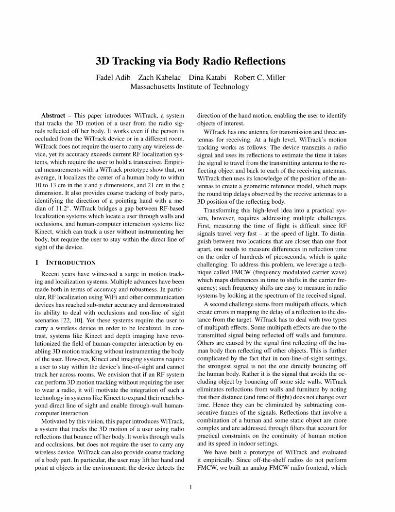
(a) Antenna “T” Setup (b) FMCW Signal Generation
Figure 1—WiTrack’s Setup and Signal Generation. (a) showsWiTrack’s directional antennas (dimension of each antenna: 5cm×5cm)arranged in a “T”: the transmit antenna is placed at the crossing pointof the T, whereas the receive antennas are on the edges. (b) shows thehardware we built to generate FMCW signals.
estimate to eliminate multipath effects and abrupt jumpsdue to noise.
2. 3D Localization: Once it obtains the TOF as perceivedfrom each of its receiving antennas, WiTrack leverages thegeometric placement of its antennas to localize the movingbody in 3D.
3. Fall Detection and Pointing: WiTrack builds on the 3D lo-calization primitive to enable new functionalities. Specifi-cally, WiTrack can detect a fall by monitoring fast changesin the elevation of a human and the final elevation afterthe change. WiTrack can also differentiate an arm motionfrom a whole body motion; it can track the motion of rais-ing one’s arm, localize the initial and final position of thearm, and determine the direction in which the arm is point-ing.
4 TIME-OF-FLIGHT ESTIMATION
The first step for WiTrack is to measure the TOF fromits transmit antenna to each of its receive antennas andclean this estimate from the effect of multi-path.
4.1 Obtaining Time-of-Flight Estimates
A straightforward approach for estimating the timeof flight is to transmit a very short pulse and measurethe delay between the transmitted pulse and its receivedecho. Such a design requires sampling the time signal atsub-nanosecond intervals i.e., it requires very high speedanalog-to-digital converters (ADCs) that operate at multi-ple GS/s. Such ADCs are high power, expensive, and havelow bit resolution, making this approach unattractive inpractice.
Instead, WiTrack measures the TOF by leveraginga technique called Frequency-Modulated Carrier Waves(FMCW). We explain FMCW at a high level, and referthe reader to [11] for a more detailed explanation. FMCWtransmits a narrowband signal (e.g., a few KHz) whosecarrier frequency changes linearly with time. To identifythe distance from a reflector, FMWC compares the car-rier frequency of the reflected signal to that of the trans-
3
f0#t#
fx(t)# fy(t)#
Δf#
TOF#
sweep#1# sweep#2#
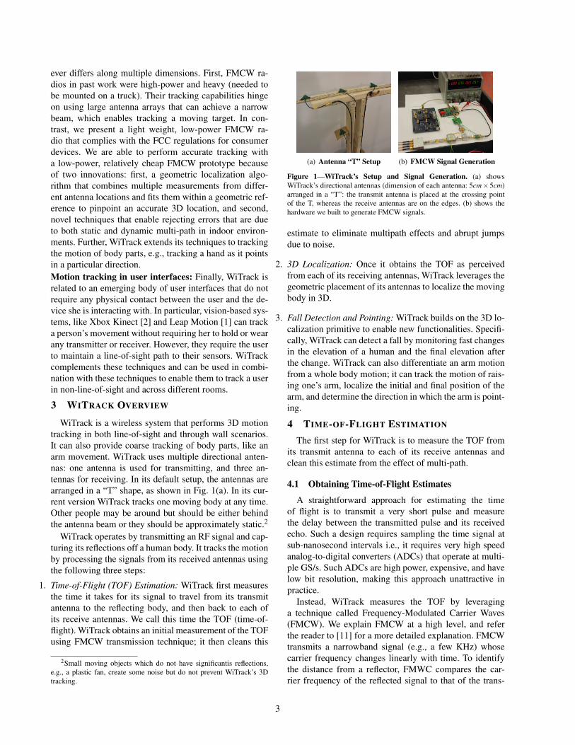
Figure 2—FMCW operation. The transmitted signal has a carrier fre-quency fx(t) that is repeatedly swept in time. Because the received signalis time-shifted with respect to the transmitted signal, its carrier frequencyfy(t) is frequency-shifted with respect to fx(t).
mitted signal. Since the carrier frequency is changing lin-early in time, delays in the reflected signals translate intofrequency shifts in comparison to the transmitted wave.Therefore, by comparing the frequency difference betweenthe transmitted signal and the received signal, one can dis-cover the time delay that the signal incurred, which corre-sponds to the TOF of that signal.
Fig. 2 illustrates this concept. The green line is the car-rier frequency of the transmitted signal which sweeps lin-early with time. The red line is the carrier frequency ofthe reflected signal as a function of time. The time shiftbetween the two is the time-of-flight (TOF) for that reflec-tor. The frequency shift ∆f between the transmitted and re-ceived signals is a function of both the slope of the sweepand the TOF, i.e.:
TOF = ∆f /slope (1)
Though the above description is for a single reflector, itcan be easily generalized to an environment with many re-flectors. In this case, the transmitted signal would still con-sist of a single carrier wave that is linearly swept in time.However, because wireless reflections add up linearly overthe medium, the received signal is a linear combination ofmultiple reflections, each of them shifted by some ∆f thatcorresponds to its own TOF. Hence once can extract allof these TOFs by taking an FFT of the received basebandsignal.3
In comparison to transmitting a very short pulse andmeasuring its sub-nanosecond delay in the time domain,FMCW does not require high speed ADCs because at anypoint in time, the received baseband signal is narrowband.FMCW Resolution: It is important to note that the reso-lution of an FMCW system is a function of the total band-width that the carrier frequency sweeps [11]. The resolu-tion is defined by the ability to distinguish between twonearby locations, which depends on the ability to distin-guish their TOFs, which itself depends on the resolution indistinguishing frequency shifts ∆f . The resolution of iden-tifying frequency shifts is equal to the size of one bin of
3The baseband signal is the received signal after mixing it by thetransmitted carrier. The mixing shifts the spectrum of the received sig-nal by the transmitted carrier frequency.
the FFT. The FFT is typically taken over a duration of onesweep of the carrier frequency and hence the size of oneFFT bin is 1/Tsweep. Since the minimum measurable fre-quency shift is ∆fmin = 1/Tsweep, the minimum measurablechange in location is:
Resolution = CTOFmin
2= C
∆fmin
2× slope, (2)
where C is the speed of light and the factor 2 accounts forthe fact that the reflected signal traverses the path back andforth.
The slope however is equal to the total swept bandwidthB divided by the sweep time Tsweep. Hence after substitut-ing for the slope in the above equation we get:
Resolution =C2B
(3)
Since C is very large, obtaining high resolution requiresa large B, i.e., the system has to take a narrowband signaland sweep its carrier frequency across a wide bandwidthof multiple GHz.
In our design we chose the following parameter for ourFMCW. We have built an FMCW system that sweeps a to-tal bandwidth of 1.69 GHz from 5.56 GHz to 7.25 GHz,and transmits at 0.75 milliWatts. The choice of this band-width has been dictated by the FCC regulations for civilianuse of spectrum [3]. Specifically, it is the largest contigu-ous bandwidth below 10 GHz which is available for civil-ian use at low power.
Based on Eq. 3, our sweep bandwidth allows us to ob-tain a distance resolution of 8.8 cm. Hence the averageerror in mapping TOF to distance in 1D is about 4.4 cm.Note that the above derivation neglects the impact of noise,and hence provides a lower bound on the achievable res-olution. In practice, the system’s resolution is affected bythe noise level. It also depends on the geometric model thatmaps TOFs to 3D locations.
4.2 Addressing Static Multi-path
The next step in WiTrack’s operation is to distinguisha human’s reflections from reflections off other objectsin the environment, like furniture and walls. Recall fromthe previous section that every reflector in the environ-ment contributes a component to the overall received sig-nal, and that component has a frequency shift that is lin-early related to the time-of-flight of the reflection based onEq. 1. Typically, reflections from walls and furniture aremuch stronger than reflections from a human, especially ifthe human is behind a wall. Unless these reflections areremoved, they would mask the signal coming from thehuman and prevent sensing her motion. This behavior iscalled the “Flash Effect”.
To remove reflections from all of these static objects(walls, furniture), we leverage the fact that since thesereflectors are static, their distance to the WiTrack device
4

0 5 10 15 20Time (seconds)
0
5
10
15
20
25
30
Dis
tan
ce
(m
ete
rs)
(a) Spectrogram
0 5 10 15 20Time (seconds)
0
5
10
15
20
25
30
Dis
tan
ce
(m
ete
rs)
(b) After Background Subtraction
0
5
10
15
20
25
30
0 5 10 15 20
Dis
tan
ce
(in
me
ters
)
Time (in seconds)
Contour Denoised Contour
(c) Contour Tracking
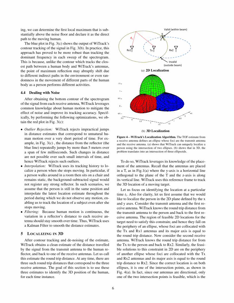
Figure 3—Obtaining the Time-of-Flight (TOF) Estimates. WiTrack takes an FFT of the received signal in baseband over every sweep period togenerate the spectogram in (a). Then, by subtracting out a given frame from the frame that precedes it, WiTrack eliminates static multipath as in (b).The blue plot in (c) shows how WiTrack can address dynamic multipath by tracking the bottom contour of (b), and then denoise the signal (red plot) toobtain a clean TOF estimate.
does not change over time, and therefore their induced fre-quency shift stays constant over time. Fig. 3(a) plots thespectrogram of the received signal as a function of time,for one of the receive antennas of WiTrack. In particular,we take the FFT of the received signal every sweep win-dow, and compute the power in each frequency as a func-tion of time. Note that there is a linear relation betweenfrequency shifts and the traveled distances as follows:
distance = C×TOF = C× ∆fslope
. (4)
Thus, instead of plotting the power in each frequency as afunction of time, we can use the above equation to plot thepower reflected from each distance as a function time, asshown in Fig. 3(a). The color code of the plot correspondsto a heat-map of the power in the reflected signal. Strongreflectors are indicated by red and orange colors, weakerreflectors are indicated by yellow and green, and the ab-sence of a reflector is indicated by blue at the correspond-ing frequency. The figure indicates the presence of verystrong static reflectors in the environment. Specifically, ithas many horizontal stripes; each of these stripes signifiesthe presence of a reflector at the corresponding round-tripdistance. Because these stripes are horizontal, their cor-responding reflectors are stationary over time. Hence, wecan eliminate the power from these static reflectors by sim-ply subtracting the output of the FFT in a given sweepfrom the FFT of the signal in the previous sweep. Thisprocess is called background subtraction because it elimi-nates all the static reflectors in the background.
Fig. 3(b) is the result of applying background subtrac-tion to Fig. 3(a). The figure shows that all static reflec-tors corresponding to the horizontal lines have been elim-inated. This has made it easier to see the much weaker re-flections from a moving human. In particular, we can seethat the distance of the dominant reflector (the red colorsignal) is varying with time, indicating that the reflector ismoving.
4.3 Addressing Dynamic Multi-path
By eliminating all reflections from static objects,WiTrack is left only with reflections from a moving hu-man (see Fig. 3(b)). These reflections include both signalsthat bounce off the human body to the receive antennas,and those that bounce off the human then bounce off otherobjects in the environment before reaching WiTrack’s an-tennas. We refer to these indirect reflections as dynamicmulti-path. It is quite possible that a human reflection thatarrives along an indirect path, bouncing off a side wall,is stronger than her direct reflection (which could be sev-erly attenuated after traversing a wall) because the formermight be able to avoid occlusion.
Our idea for eliminating dynamic multi-path is basedon the observation that, at any point in time, the direct sig-nal reflected from the human to our device has travelled ashorter path than indirect reflections. Because distance isdirectly related to TOF, and hence to frequency, this meansthat the direct signal reflected from the human would resultin the smallest frequency shift among all strong reflectorsafter background subtraction.
We can track the reflection that traveled the shortest pathby tracing the bottom contour of all strong reflectors inFig. 3(b). The bottom contour can be defined as the closestlocal maximum to our device. To determine the first localmaximum that is caused by human motion, we must beable to distinguish it from a local maximum due to a noisepeak. We achieve this distinguishability by averaging thespectrogram across multiple sweeps. In our implementa-tion, we average over five consecutive sweeps, which to-gether span a duration of 12.5 ms. For all practical pur-poses, a human can be considered as static over this timeduration; therefore, the spectrogram would be consistentover this duration. Averaging allows us to boost the powerof a reflection from a human while diluting the peaks thatare due to noise. This is because the human reflections areconsistent and hence add up coherently, whereas the noiseis random and hence adds up incoherently. After averag-
5
ing, we can determine the first local maximum that is sub-stantially above the noise floor and declare it as the directpath to the moving human.
The blue plot in Fig. 3(c) shows the output of WiTrack’scontour tracking of the signal in Fig. 3(b). In practice, thisapproach has proved to be more robust than tracking thedominant frequency in each sweep of the spectrogram.This is because, unlike the contour which tracks the clos-est path between a human body and WiTrack’s antennas,the point of maximum reflection may abruptly shift dueto different indirect paths in the environment or even ran-domness in the movement of different parts of the humanbody as a person performs different activities.
4.4 Dealing with Noise
After obtaining the bottom contour of the spectrogramof the signal from each receive antenna, WiTrack leveragescommon knowledge about human motion to mitigate theeffect of noise and improve its tracking accuracy. Specif-ically, by performing the following optimizations, we ob-tain the red plot in Fig. 3(c):
• Outlier Rejection: WiTrack rejects impractical jumpsin distance estimates that correspond to unnatural hu-man motion over a very short period of time. For ex-ample, in Fig. 3(c) , the distance from the reflector (theblue line) repeatedly jumps by more than 5 meters overa span of few milliseconds. Such changes in distanceare not possible over such small intervals of time, andhence WiTrack rejects such outliers.
• Interpolation: WiTrack uses its tracking history to lo-calize a person when she stops moving. In particular, ifa person walks around in a room then sits on a chair andremains static, the background-subtracted signal wouldnot register any strong reflector. In such scenarios, weassume that the person is still in the same position andinterpolate the latest location estimate throughout theperiod during which we do not observe any motion, en-abling us to track the location of a subject even after shestops moving.
• Filtering: Because human motion is continuous, thevariation in a reflector’s distance to each receive an-tenna should stay smooth over time. Thus, WiTrack usesa Kalman Filter to smooth the distance estimates.
5 LOCALIZING IN 3DAfter contour tracking and de-noising of the estimate,
WiTrack obtains a clean estimate of the distance travelledby the signal from the transmit antenna to the human re-flector, and back to one of the receive antennas. Let us callthis estimate the round trip distance. At any time, there arethree such round trip distances that correspond to the threereceive antennas. The goal of this section is to use thesethree estimates to identify the 3D position of the human,for each time instance.
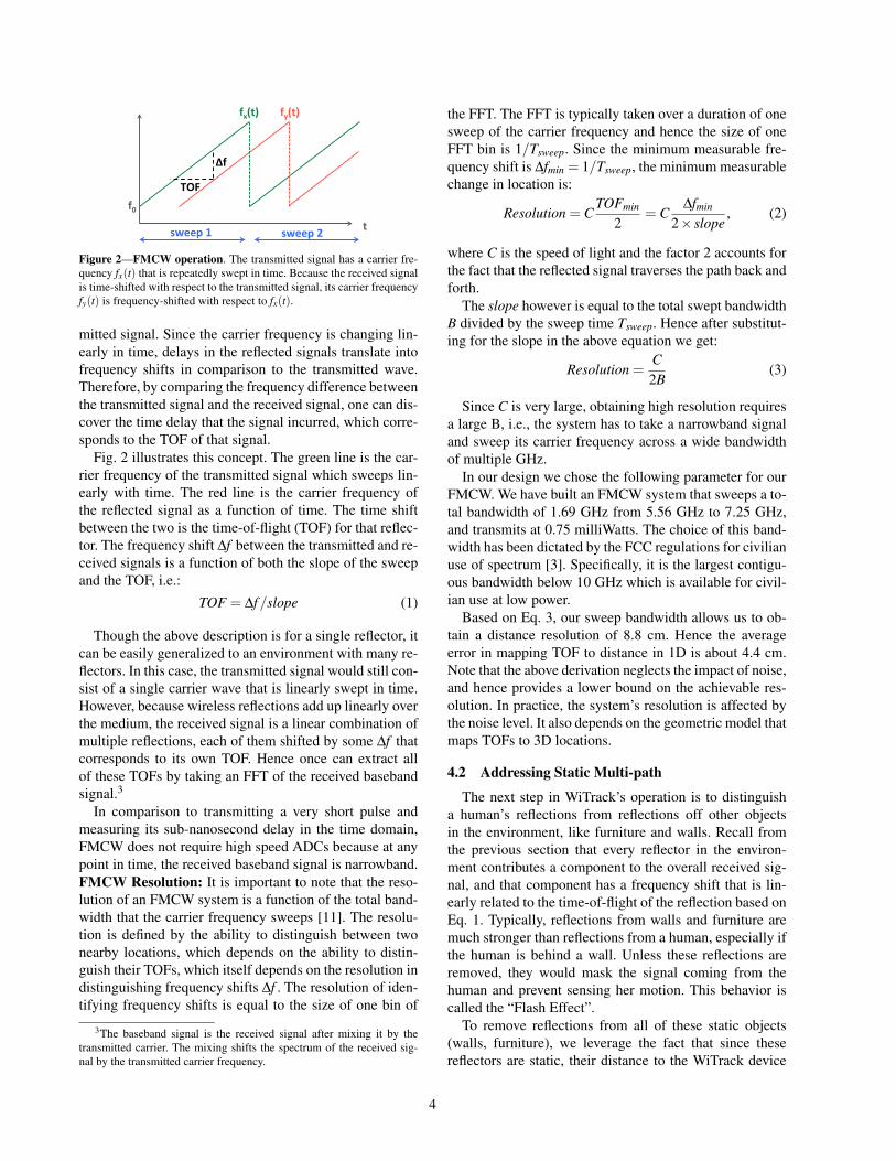
Tx Rx1 Rx2
Invalid (outside beam)
d1
Valid (within beam)
(a) 2D Localization
(b) 3D Localization
Figure 4—WiTrack’s Localization Algorithm. The TOF estimate froma receive antenna defines an ellipse whose foci are the transmit antennaand the receive antenna. (a) shows that WiTrack can uniquely localize aperson using the intersection of two ellipses. (b) shows that in 3D, theproblem translates into an intersection of three ellipsoids.
To do so, WiTrack leverages its knowledge of the place-ment of the antennas. Recall that the antennas are placedin a T, as in Fig.1(a) where the y-axis is a horizontal lineorthogonal to the plane of the T and the z-axis is alongits vertical line. WiTrack uses this reference frame to trackthe 3D location of a moving target.
Let us focus on identifying the location at a particulartime ti. Also for clarity, let us first assume that we wouldlike to localize the person in the 2D plane defined by the xand y axes. Consider the transmit antenna and the first re-ceive antenna. WiTrack knows the round trip distance fromthe transmit antenna to the person and back to the first re-ceive antenna. The region of feasible 2D locations for thetarget need to satisfy this constrain; and hence they fall onthe periphery of an ellipse, whose foci are collocated withthe Tx and Rx1 antennas and its major axis is equal tothe round trip distance. Now consider the second receiveantenna. WiTrack knows the round trip distance for fromthe Tx to the person and back to Rx2. Similarly, the feasi-ble solutions to this constraint in 2D are on the peripheryof another ellipse whose foci are collocated with the Txand Rx2 antennas and its major axis is equal to the roundtrip distance to Rx2. Since the correct location is on bothellipses, it is one of the intersection points, as shown inFig. 4(a). In fact, since our antennas are directional, onlyone of the two intersection points is feasible, which is the
6
one that yield a location in the direction of the antennasbeams.
It is straightforward to generalize the argument to lo-calizing in 3D. Specifically, in a 3D space, the round-tripdistance defines an ellipsoid whose two foci are the trans-mit antenna and one of the receive antennas. In this set-ting, the intersection of two ellipsoids would define an arcin the 3D space, and hence is insufficient to pinpoint the3D location of a person. However, by adding a third direc-tional antenna, we obtain a unique solution in 3D that iswithin the beam of all the directional antennas as shown inFig. 4(b). Therefore, our algorithm can localize a personin 3D by using three directional receive antennas.
Finally we note two points:• The T-shape placement for the antennas is chosen be-
cause we assume the user wants to localize motion be-hind a wall, in which case all the antennas would haveto be arranged in one plane facing the wall. We placeone antenna below to help determine elevation, whilethe others are on the same level.
• While the minimum number of Rx antennas necessaryto resolve a 3D location is three, adding more antennaswould result in more constraints. This would allow us toover-constrain the solution and hence add extra robust-ness to noise.
6 BEYOND 3D TRACKING
In this section, we build on WiTrack’s 3D localizationprimitive to enable two additional capabilities: estimatinga pointing direction from the corresponding arm move-ment, and detecting a fall.
6.1 Estimation of Pointing Angle
We explain how WiTrack provides coarse estimation ofbody part motion. We consider the following motion: theuser starts from a state where her arm is rested next toher body. She raises the arm in a direction of her choicewith the intention of pointing toward a device or appliance,and then drops her hand to the first position. The user maymove around and at a random time perform the pointinggesture. We require however that the user be standing (i.e.,not walking) when performing the pointing gesture. Thegoal is to detect the pointing direction.
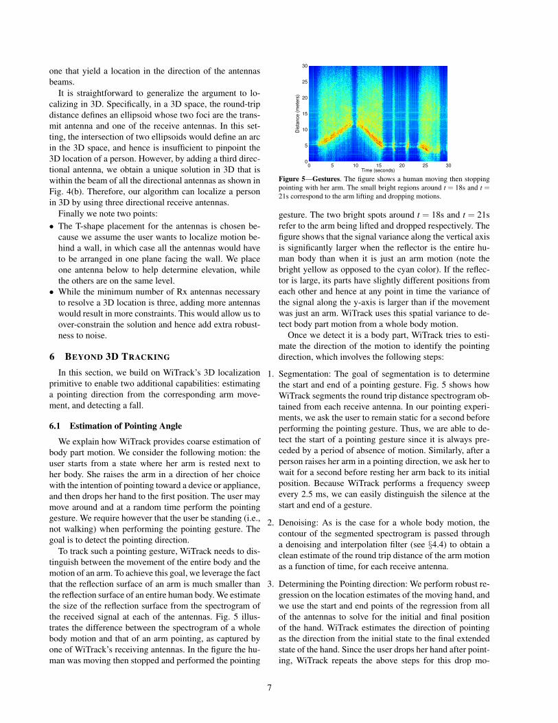
To track such a pointing gesture, WiTrack needs to dis-tinguish between the movement of the entire body and themotion of an arm. To achieve this goal, we leverage the factthat the reflection surface of an arm is much smaller thanthe reflection surface of an entire human body. We estimatethe size of the reflection surface from the spectrogram ofthe received signal at each of the antennas. Fig. 5 illus-trates the difference between the spectrogram of a wholebody motion and that of an arm pointing, as captured byone of WiTrack’s receiving antennas. In the figure the hu-man was moving then stopped and performed the pointing
0 5 10 15 20 25 30Time (seconds)
0
5
10
15
20
25
30
Dis
tance (
mete
rs)
Figure 5—Gestures. The figure shows a human moving then stoppingpointing with her arm. The small bright regions around t = 18s and t =21s correspond to the arm lifting and dropping motions.
gesture. The two bright spots around t = 18s and t = 21srefer to the arm being lifted and dropped respectively. Thefigure shows that the signal variance along the vertical axisis significantly larger when the reflector is the entire hu-man body than when it is just an arm motion (note thebright yellow as opposed to the cyan color). If the reflec-tor is large, its parts have slightly different positions fromeach other and hence at any point in time the variance ofthe signal along the y-axis is larger than if the movementwas just an arm. WiTrack uses this spatial variance to de-tect body part motion from a whole body motion.
Once we detect it is a body part, WiTrack tries to esti-mate the direction of the motion to identify the pointingdirection, which involves the following steps:
1. Segmentation: The goal of segmentation is to determinethe start and end of a pointing gesture. Fig. 5 shows howWiTrack segments the round trip distance spectrogram ob-tained from each receive antenna. In our pointing experi-ments, we ask the user to remain static for a second beforeperforming the pointing gesture. Thus, we are able to de-tect the start of a pointing gesture since it is always pre-ceded by a period of absence of motion. Similarly, after aperson raises her arm in a pointing direction, we ask her towait for a second before resting her arm back to its initialposition. Because WiTrack performs a frequency sweepevery 2.5 ms, we can easily distinguish the silence at thestart and end of a gesture.
2. Denoising: As is the case for a whole body motion, thecontour of the segmented spectrogram is passed througha denoising and interpolation filter (see §4.4) to obtain aclean estimate of the round trip distance of the arm motionas a function of time, for each receive antenna.
3. Determining the Pointing direction: We perform robust re-gression on the location estimates of the moving hand, andwe use the start and end points of the regression from allof the antennas to solve for the initial and final positionof the hand. WiTrack estimates the direction of pointingas the direction from the initial state to the final extendedstate of the hand. Since the user drops her hand after point-ing, WiTrack repeats the above steps for this drop mo-
7

tion obtaining a second estimate of the pointing direction.Then, WiTrack estimates the pointing direction as the mid-dle direction between the two.4 Being able to leverage theapproximate mirroring effect between the arm lifting andarm dropping motions adds significant robustness to theestimation of the pointing angle.
We envision that an application of the estimation ofpointing direction can be to enable a user to control house-hold appliances by simply pointing at them. Given a list ofinstrumented devices and their locations, WiTrack wouldtrack the user’s hand motion, determine the direction inwhich she points, and commands the device to change itsmode (e.g., turn on or off the lights, or control our blinds).
Finally, to demonstrate the pointing gesture within thecontext of an application, we created a setup where theuser can control the operation mode of a device or appli-ance by pointing at it. Based on the current 3D position ofthe user and the direction of her hand, WiTrack automat-ically identifies the desired appliance from a small set ofappliances that we instrumented (lamp, computer screen,automatic shades). Our instrumentation is a basic modechange (turn on or turn off). WiTrack issues a commandvia Insteon home drivers to control the devices. We en-vision that this setup can evolve to support a larger set offunctionalities and be integrated within a home automationsystems [9].
6.2 Fall DetectionOur objective is to automatically distinguish a fall from
other activities including sitting on the ground, sitting ona chair and walking. To do so, we build on WiTrack’s ele-vation tracking along the z dimension. Note that simplychecking the person’s elevation is not sufficient to dis-tinguish falls from sitting on the floor. To detect a fall,WiTrack requires two conditions to be met: First, the per-son’s elevation along the z axis must change significantly(by more than one third of its value), and the final value forher elevation must be close to the ground level. The secondcondition is the change in elevation has to occur within avery short period to reflect that people fall quicker thanthey sit.
Fig. 6 plots WiTrack’s estimate of the elevation alongthe z dimension for four activities: a person walking, sit-ting on a chair, sitting on the ground, and (simulated)falling on the ground.5 The figure confirms that walkingand sitting on a chair can be identified from falling andsitting on the floor based on elevation because the final el-evation is far from z = 0. However, to distinguish a fall onthe ground from a sitting on the ground, one has to exploitthat during a fall the person changes her elevation fasterthan when she voluntarily sits on the floor.
4by zooming on Fig. 5 the reader can see how the arm lifting anddropping motions approximately mirror each other’s tilt.
5The fall was performed in a padded room as detailed in 9.5.
0
0.5
1
1.5
2
0 5 10 15 20 25 30
Ele
va
tio
n (
in m
ete
rs)
Time (in seconds)
WalkSit on ChairSit on GroundFall
Figure 6—Fall Detection. WiTrack automatically detects falls by moni-toring the absolute value and the change in elevation.
Phase#Frequency#Detector#
VCO#
Digital#Synthesizer#
Frequency#Divider#
BandPass#Filter# Amp#
X# HighPass#Filter#USRP# LNA#
Tx#
Rx1#
Signal#Genera1on#
Rxn#
Figure 7—Schematic of the Front End Design. WiTrack’s front endconsists of an FMCW signal generation component, and a receive chainthat is connected to a USRP.
7 IMPLEMENTATION
FMCW Radio Front-End Hardware: We have builtan FMCW front-end that operates as a daughterboard forthe USRP software radio. Below, we describe our design,which is illustrated in the schematic of Fig. 7.
The first step of our front end design is the generationof an FMCW signal, which consists of a narrowband sig-nal whose carrier frequency is linearly swept over a largebandwidth. This signal can be obtained by using a voltage-controlled oscillator (VCO). Because the output frequencyof a VCO is a linear function of its input voltage, we cangenerate our desired frequency sweep by feeding a volt-age sweep as an input to the VCO. However, small errorsin the input voltage can create large non-linearities in theoutput sweep.
To obtain a highly linear sweep, we use a feedbackmechanism. Specifically, we use a phase frequency de-tector to compare the output frequency of the VCO witha highly accurate reference signal, and use the offset be-tween the two to control the VCO. Note that even thoughthe reference signal needs to be highly accurate, it doesnot need to span the same bandwidth as our desired out-put signal. In particular, rather than directly comparingthe output of the VCO to the reference signal, we firstuse a frequency divider. This allows us to use a refer-ence signal that sweeps from 136.5 MHz to 181.25 MHzto generate an FMCW signal that sweeps from 5.46 GHzto 7.25 GHz. This FMCW signal is transmitted over theair using WA5VJB directional antennas after filtering andamplification.
At the receive chain, the transmitted signal is capturedusing WA5VJB directional antennas and passed through
8

a low-noise amplifier and a high-pass filter to improveits SNR. Recall from §4 that an FMCW receiver deter-mines the TOF by measuring the frequency offset betweenthe transmitted and the received signal. This offset can beobtained by downconverting (mixing) the received signalwith the transmitted signal. The output of the mixer is thenfed to the LFRX-LF daughterboard on USRP2 which sam-ples it at 1 MHz and passes the digitized samples to theUHD driver.Real-time Software Processing: The implemented proto-type performs real-time 3D motion tracking as describedin §4, §5 and §6. Tracking is implemented directly in theUHD driver of the USRP software radio. The signal fromeach receiving antenna is transformed to the Frequency do-main using an FFT whose size matches the FMCW sweepperiod of 2.5ms. To improve resilience to noise, every fiveconsecutive sweeps are averaged creating one FFT frame.Background subtraction is performed by subtracting theaveraged FFT frame from the frame that precedes it. Thespectrogram is processed for contour tracking by identi-fying for each time instance the smallest local frequencymaximum that is significantly higher than the noise level.Outlier rejection is performed by declaring that the contourshould not jump significantly between two successive FFTframes (because a person cannot move much in 12.5ms).The output is smoothed with a Kalman filter.
To locate a person, instead of solving a system of ellip-soid equations in real-time, we leverage that the location ofthe antennas does not change and is known a priori. Thus,before running our experiments, we use MATLAB’s sym-bolic library to find a symbolic representation of the solu-tions (x,y,z) as a function of symbolic TOF to each of thereceiving antennas. This means that the ellipsoid equationsneed to be solved only once (for any fixed antenna posi-tioning), independent of the location of the tracked per-son. After it obtains the 3D location of a person, WiTrackuses python’s matplotlib library to output this location inreal-time.
Software processing has a total delay less than 75 msbetween when the signal is received an a corresponding3D location is output.
8 EVALUATION
We empirically evaluate the performance of theWiTrack prototype by conducting experiments in our labbuilding with 11 human users.(a) Ground Truth: We determine WiTrack’s localizationaccuracy by testing it against the VICON motion capturesystem. The VICON is a multi-hundred-thousand dollarsystem used in filmmaking and video game developmentto track the human motion and map it to a 3D characteranimation model. It uses calibrated infrared cameras andrecords motion by instrumenting the tracked body withinfrared-reflective markers. The VICON system has a sub-centimeter accuracy and hence we use it to determine the
ground truth location. To track a moving person with theVICON, she is asked to wear a jacket and a hat, whichare instrumented with eight infrared markers. To track asubject’s hand, she is asked to wear a glove that is also in-strumented with six VICON markers. The VICON tracksthe infrared markers on the subject’s body and fits them toa 3D human model to identify the location of the subject.
The VICON system has a built-in capability that cantrack the center of any object using the infrared-reflectivemarkers that are placed on that object. This allows us todetermine the center position of a human subject who iswearing the instrumented jacket and hat. WiTrack how-ever computes the 3D location of the body surface wherethe signal reflects. In order to compare WiTrack’s mea-surements to those by the VICON we need to have an es-timate of the depth of the center with respect to the bodysurface. Thus, we use the VICON to run offline measure-ments with the person standing and having infrared mark-ers around her body at the same height as the WiTracktransmit antenna (about the waist). We use the VICON tomeasure the average depth of the center from surface foreach person. To compare the 3D location computed by thetwo systems, we first compensate for the average distancebetween the center and surface for that person and thentake the Euclidian distance.(b) Device Setup WiTrack is placed behind the wall of theVICON room. The device uses one transmit antenna andthree receive antennas. The transmit antenna and two re-ceive antennas are lined up parallel to the wall, and a thirdreceive antenna is placed below the transmit antenna. Thedistance between the transmit antenna and each receive an-tenna is 1m, unless otherwise noted in the experimentalsetup.(c) Human Subjects The experiments are performed witheleven human subjects: two females and nine males. Thesubjects are of different heights and builds, and span anage range of 22 to 56 years. In each experiment, the subjectis asked to move at will in the VICON room; he/she istracked using both the VICON system and WiTrack. Notethat WiTrack tracks the subject through the wall, from anadjacent room, while the VICON has to be within directline of sight from the subject.
9 PERFORMANCE RESULTS9.1 Accuracy of 3D Tracking
We first focus on the developed 3D tracking primitiveand evaluate its accuracy across all three dimensions.
We run 100 experiments each lasting for 1 minute, dur-ing which a human subject moves at will in the VICONroom. The VICON room has no windows. It has 6-inchhollow walls supported by steel frames with sheet rock ontop, which is a standard setup for office buildings. TheWiTrack prototype is placed outside the room with alltransmit and receive antennas facing one of the walls ofthe VICON room. Recall that WiTrack’s antennas are di-
9
0
0.2
0.4
0.6
0.8
1
0 20 40 60 80 100
Fra
ction o
f m
easure
ments
Location Error (in centimeters)
x dimensiony dimensionz dimension
(a) CDF in line-of-sight
0
0.2
0.4
0.6
0.8
1
0 20 40 60 80 100
Fra
ction o
f m
easure
ments
Location Error (in centimeters)
x dimensiony dimensionz dimension
(b) CDF through-wall
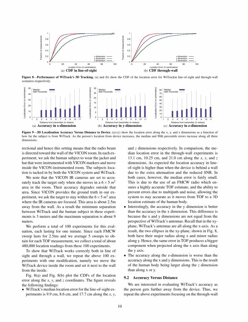
Figure 8—Performance of WiTrack’s 3D Tracking. (a) and (b) show the CDF of the location error for WiTrackin line-of-sight and through-wallscenarios respectively.
0
10
20
30
40
50
1 2 3 4 5 6 7 8 9 10 11
Lo
ca
liza
tio
n E
rro
r (in
ce
ntim
ete
rs)
Distance from transmitter (in meters)
Median90th Percentile
(a) Accuracy in x-dimension
0
5
10
15
20
25
30
1 2 3 4 5 6 7 8 9 10 11
Lo
ca
liza
tio
n E
rro
r (in
ce
ntim
ete
rs)
Distance from transmitter (in meters)
Median90th Percentile
(b) Accuracy in y-dimension
0
10
20
30
40
50
60
70
80
1 2 3 4 5 6 7 8 9 10 11
Lo
ca
liza
tio
n E
rro
r (in
ce
ntim
ete
rs)
Distance from transmitter (in meters)
Median90th Percentile
(c) Accuracy in z-dimension
Figure 9—3D Localization Accuracy Versus Distance to Device. (a)-(c) show the location error along the x, y, and z dimensions as a function ofhow far the subject is from WiTrack. As the person’s location from device increases, the median and 90th percentile errors increase along all threedimensions.
rectional and hence this setting means that the radio beamis directed toward the wall of the VICON room. In each ex-periment, we ask the human subject to wear the jacket andhat that were instrumented with VICON markers and moveinside the VICON-instrumented room. The subjects loca-tion is tacked in by both the VICON system and WiTrack.
We note that the VICON IR cameras are set to accu-rately track the target only when she moves in a 6× 5 m2
area in the room. Their accuracy degrades outside thatarea. Since VICON provides the ground truth in our ex-periment, we ask the target to stay within the 6×5 m2 areawhere the IR cameras are focused. This area is about 2.5maway from the wall. As a result the minimum separationbetween WiTrack and the human subject in these experi-ments is 3 meters and the maximum separation is about 9meters.
We perform a total of 100 experiments for this eval-uation, each lasting for one minute. Since each FMCWsweep lasts for 2.5ms and we average 5 sweeps to ob-tain for each TOF measurement, we collect a total of about480,000 location readings from these 100 experiments.
To show that WiTrack works correctly both in line ofsight and through a wall, we repeat the above 100 ex-periments with one modification, namely we move theWiTrack device inside the room and set it next to the wallfrom the inside.
Fig. 8(a) and Fig. 8(b) plot the CDFs of the locationerror along the x, y, and z coordinates. The figure revealsthe following findings:• WiTrack’s median location error for the line-of-sight ex-
periments is 9.9 cm, 8.6 cm, and 17.7 cm along the x, y,
and z dimensions respectively. In comparison, the me-dian location error in the through-wall experiments is13.1 cm, 10.25 cm, and 21.0 cm along the x, y, and zdimensions. As expected the location accuracy in line-of-sight is higher than when the device is behind a walldue to the extra attenuation and the reduced SNR. Inboth cases, however, the median error is fairly small.This is due to the use of an FMCW radio which en-sures a highly accurate TOF estimate, and the ability toprevent errors due to multipath and noise, allowing thesystem to stay accurate as it moves from TOF to a 3Dlocation estimate of the human body.• Interestingly, the accuracy in the y dimension is better
than the accuracy in the x dimension. This difference isbecause the x and y dimensions are not equal from theperspective of WiTrack’s antennas. Recall that in the xy-plane, WiTrack’s antennas are all along the x-axis. As aresult, the two ellipses in the xy-plane, shown in Fig. 8,both have their major radius along x and minor radiusalong y. Hence, the same error in TOF produces a biggercomponent when projected along the x axis than alongthe y axis.• The accuracy along the z-dimension is worse than the
accuracy along the x and y dimensions. This is the resultof the human body being larger along the z dimensionthan along x or y.
9.2 Accuracy Versus Distance
We are interested in evaluating WiTrack’s accuracy asthe person gets further away from the device. Thus, werepeat the above experiments focusing on the through-wall
10

0
10
20
30
40
50
60
70
0 0.25 0.5 0.75 1 1.25 1.5 1.75 2
Lo
ca
liza
tio
n E
rro
r (in
ce
ntim
ete
rs)
Antenna Separation (in meters)
Median90th Percentile
(a) Accuracy in x-dimension
0
5
10
15
20
25
30
35
40
0 0.25 0.5 0.75 1 1.25 1.5 1.75 2
Lo
ca
liza
tio
n E
rro
r (in
ce
ntim
ete
rs)
Antenna Separation (in meters)
Median90th Percentile
(b) Accuracy in y-dimension
0
20
40
60
80
100
120
0 0.25 0.5 0.75 1 1.25 1.5 1.75 2
Lo
ca
liza
tio
n E
rro
r (in
ce
ntim
ete
rs)
Antenna Separation (in meters)
Median90th Percentile
(c) Accuracy in z-dimension
Figure 10—3D Localization Accuracy Versus Size of Device. (a)-(c) show the median and 90th percentile location errors as a function of the antennaseparation. Along all three dimensions, a larger separation leads to a decrease in the location error.
case. As mentioned above, VICON requires the human tomove in a certain space that is in line of sight of the IRcameras. Thus, to increase the distance from WiTrack tothe human we move WiTrack away in the hallway nextto the VICON room. Again, we collect 100 experiments,each spanning one minute for a total of 480,000 locationmeasurements.
Fig. 9 plots WiTrack’s localization error as a functionof its distance to the subject. The distance to the subjectis determined using the VICON ground-truth coordinates,and rounded to the nearest meter. The figure shows themedian and 90th percentile of the estimation error for thex, y, and z coordinate.
The figure shows that the median accuracy changes by5 to 10 cm for distances that are 3 to 11 m away from thedevice. As expected, the further the human moves fromthe device, the larger the estimation error. This increase inerror with distance is expected since as the distance getslarger the signal gets more attenuated. However, a secondreason stems from the geometry of the ellipsoid-based lo-calization model. Given the equations of the ellipsoid, theTOF multiplied by the speed of light is equal to the majoraxis of the ellipsoid/ellipse that describes the user’s loca-tion, and the antenna separation is the distance between thefoci. For a fixed antenna separation, as the distance/TOFincreases the ellipsoid’s surface increases, increasing theoverall space of potential locations.
The figure also shows that the accuracy is best along they dimension, then the x, and finally the z, which is due tothe reasons discussed in the previous section.
9.3 Accuracy Versus Antenna Separation
Our default setting places the receive antennas 1 m awayfrom the transmit antenna. In this section, we examine theimpact of antenna separation on performance.
We evaluate five different configurations. In all of theseconfigurations, the transmit antenna is at an equal distancefrom all receive antennas, and is placed at the crossingpoint of a “T” whereas the receive antennas are placed atthe edges. We vary the distance between the transmit an-tenna and each of the receive antennas from 25 cm to 2 m.We run 100 one-minute experiments, 20 for each antennasetting. All experiments are run through a wall. In each ex-
periment, we ask the human subject to move at will insidethe VICON room, as we record her location using both theVICON system and WiTrack.
Fig. 10 shows WiTrack’s localization accuracy as afunction of antenna separation. The figure shows that evenif one brings the antennas to within 25cm of each other,the median location error stays less than 17 cm, 12 cm, and31 cm for the x, y, and z dimensions. The 90th of the errorbecomes 64cm, 35cm, and 116cm respectively. While thisis higher than the previous results where the antennas wereseparated by 1 m, it is still comparable to state of the artlocalization using a WiFi transmitter (in our case the userdoes not need to carry any wireless device).
The plots show that as the antenna separation increases,the localization accuracy improves along all three dimen-sions x, y, and z. This behavior is expected, because thefurther the receive antennas are from each other, the largerthe spatial diversity between them. Because of the geo-metric nature of the algorithm, a spatially diverse setupwould lead to a smaller intersection curve between anypair of ellipsoids. For this reason, in a larger setup, thesame noise variance in the TOF estimates would be con-fined to a smaller curve, thus, minimizing estimate error.
Mathematically, for any TOF, the antenna separation isthe distance between the foci of the ellipsoid that definesthe person’s location. Hence for any given TOF, increas-ing the antenna separation increases the distance betweenthe foci while keeping the ellipsoids major radius constant.Hence the ellipsoid gets more squashed and its circumfer-ence becomes smaller, reducing the region of potential so-lutions.
9.4 Accuracy of Estimating Pointing Direction
In the experiments in this section, the human subjectswear a glove that is instrumented with infrared reflexivemarkers, and are asked to stand in a given location insidethe VICON room and point in a direction of their choice.Each pointing gesture consists of raising the subject’s handin the direction of her choice, followed by the subject re-turning her hand to its original resting position. Across ourexperiments, we ask the human subjects to stand in ran-dom different locations in the VICON room and perform
11
0
0.2
0.4
0.6
0.8
1
0 20 40 60 80 100
Fra
ction o
f m
easure
ments
Orientation Accuracy (in degrees)
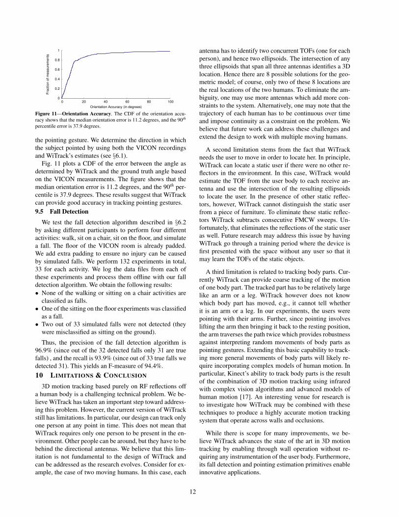
Figure 11—Orientation Accuracy. The CDF of the orientation accu-racy shows that the median orientation error is 11.2 degrees, and the 90th
percentile error is 37.9 degrees.
the pointing gesture. We determine the direction in whichthe subject pointed by using both the VICON recordingsand WiTrack’s estimates (see §6.1).
Fig. 11 plots a CDF of the error between the angle asdetermined by WiTrack and the ground truth angle basedon the VICON measurements. The figure shows that themedian orientation error is 11.2 degrees, and the 90th per-centile is 37.9 degrees. These results suggest that WiTrackcan provide good accuracy in tracking pointing gestures.9.5 Fall Detection
We test the fall detection algorithm described in §6.2by asking different participants to perform four differentactivities: walk, sit on a chair, sit on the floor, and simulatea fall. The floor of the VICON room is already padded.We add extra padding to ensure no injury can be causedby simulated falls. We perform 132 experiments in total,33 for each activity. We log the data files from each ofthese experiments and process them offline with our falldetection algorithm. We obtain the following results:• None of the walking or sitting on a chair activities are
classified as falls.• One of the sitting on the floor experiments was classified
as a fall.• Two out of 33 simulated falls were not detected (they
were misclassified as sitting on the ground).
Thus, the precision of the fall detection algorithm is96.9% (since out of the 32 detected falls only 31 are truefalls) , and the recall is 93.9% (since out of 33 true falls wedetected 31). This yields an F-measure of 94.4%.10 LIMITATIONS & CONCLUSION
3D motion tracking based purely on RF reflections offa human body is a challenging technical problem. We be-lieve WiTrack has taken an important step toward address-ing this problem. However, the current version of WiTrackstill has limitations. In particular, our design can track onlyone person at any point in time. This does not mean thatWiTrack requires only one person to be present in the en-vironment. Other people can be around, but they have to bebehind the directional antennas. We believe that this lim-itation is not fundamental to the design of WiTrack andcan be addressed as the research evolves. Consider for ex-ample, the case of two moving humans. In this case, each
antenna has to identify two concurrent TOFs (one for eachperson), and hence two ellipsoids. The intersection of anythree ellipsoids that span all three antennas identifies a 3Dlocation. Hence there are 8 possible solutions for the geo-metric model; of course, only two of these 8 locations arethe real locations of the two humans. To eliminate the am-biguity, one may use more antennas which add more con-straints to the system. Alternatively, one may note that thetrajectory of each human has to be continuous over timeand impose continuity as a constraint on the problem. Webelieve that future work can address these challenges andextend the design to work with multiple moving humans.
A second limitation stems from the fact that WiTrackneeds the user to move in order to locate her. In principle,WiTrack can locate a static user if there were no other re-flectors in the environment. In this case, WiTrack wouldestimate the TOF from the user body to each receive an-tenna and use the intersection of the resulting ellipsoidsto locate the user. In the presence of other static reflec-tors, however, WiTrack cannot distinguish the static userfrom a piece of furniture. To eliminate these static reflec-tors WiTrack subtracts consecutive FMCW sweeps. Un-fortunately, that eliminates the reflections of the static useras well. Future research may address this issue by havingWiTrack go through a training period where the device isfirst presented with the space without any user so that itmay learn the TOFs of the static objects.
A third limitation is related to tracking body parts. Cur-rently WiTrack can provide coarse tracking of the motionof one body part. The tracked part has to be relatively largelike an arm or a leg. WiTrack however does not knowwhich body part has moved, e.g., it cannot tell whetherit is an arm or a leg. In our experiments, the users werepointing with their arms. Further, since pointing involveslifting the arm then bringing it back to the resting position,the arm traverses the path twice which provides robustnessagainst interpreting random movements of body parts aspointing gestures. Extending this basic capability to track-ing more general movements of body parts will likely re-quire incorporating complex models of human motion. Inparticular, Kinect’s ability to track body parts is the resultof the combination of 3D motion tracking using infraredwith complex vision algorithms and advanced models ofhuman motion [17]. An interesting venue for research isto investigate how WiTrack may be combined with thesetechniques to produce a highly accurate motion trackingsystem that operate across walls and occlusions.
While there is scope for many improvements, we be-lieve WiTrack advances the state of the art in 3D motiontracking by enabling through wall operation without re-quiring any instrumentation of the user body. Furthermore,its fall detection and pointing estimation primitives enableinnovative applications.
12

REFERENCES
[1] Leap Motion. https://www.leapmotion.com.[2] X-box Kinect. http://www.xbox.com. Microsoft.[3] Understanding the Fcc Regulations for Low-power, Non-
licensed Transmitters. Office of Engineering and Technol-ogy Federal Communications Commission, 1993.
[4] F. Adib and D. Katabi. See through walls with Wi-Fi! InACM SIGCOMM, 2013.
[5] P. Bahl and V. Padmanabhan. RADAR: an in-building RF-based user location and tracking system. In IEEE INFO-COM, 2000.
[6] G. Charvat, L. Kempel, E. Rothwell, C. Coleman, andE. Mokole. A through-dielectric radar imaging system.IEEE Trans. Antennas and Propagation, 2010.
[7] K. Chetty, G. Smith, and K. Woodbridge. Through-the-wall sensing of personnel using passive bistatic wifi radarat standoff distances. IEEE Trans. Geoscience and RemoteSensing, 2012.
[8] J. Dai, X. Bai, Z. Yang, Z. Shen, and D. Xuan. Perfalld:A pervasive fall detection system using mobile phones. InIEEE PERCOM, 2010.
[9] C. Dixon, R. Mahajan, S. Agarwal, A. Brush, B. Lee,S. Saroiu, and V. Bahl. An operating system for the home.In Usenix NSDI, 2012.
[10] K. Joshi, S. Hong, and S. Katti. Pinpoint: Localizing inter-fering radios. In Usenix NSDI, 2013.
[11] B. R. Mahafza. Radar systems analysis and design usingMATLAB. Chapman & Hall, 2013.
[12] N. Noury, A. Fleury, P. Rumeau, A. Bourke, G. Laighin,V. Rialle, and J. Lundy. Fall detection-principles and meth-ods. In IEEE EBMS, 2007.
[13] Q. Pu, S. Jiang, S. Gollakota, and S. Patel. Whole-homegesture recognition using wireless signals. In ACM Mobi-Com, 2013.
[14] A. Rai, K. K. Chintalapudi, V. N. Padmanabhan, andR. Sen. Zee: zero-effort crowdsourcing for indoor local-ization. In ACM MobiCom, 2012.
[15] T. Ralston, G. Charvat, and J. Peabody. Real-timethrough-wall imaging using an ultrawideband multiple-input multiple-output (MIMO) phased array radar system.In IEEE ARRAY, 2010.
[16] S. Sen, B. Radunovic, R. R. Choudhury, and T. Minka. Spotlocalization using phy layer information. In ACM MobiSys,2012.
[17] J. Shotton, T. Sharp, A. Kipman, A. Fitzgibbon, M. Finoc-chio, A. Blake, M. Cook, and R. Moore. Real-time humanpose recognition in parts from single depth images. Com-munications of the ACM, 2013.
[18] J. Wang, F. Adib, R. Knepper, D. Katabi, and D. Rus. RF-Compass: Robot Object Manipulation Using RFIDs. InACM MobiCom, 2013.
[19] J. Wang and D. Katabi. Dude, where’s my card? rfid posi-tioning that works with multipath and non-line of sight. InACM SIGCOMM, 2013.
[20] J. Wilson and N. Patwari. Radio tomographic imaging withwireless networks. In IEEE Transactions on Mobile Com-puting, 2010.
[21] J. Wilson and N. Patwari. See-through walls: Motion track-ing using variance-based radio tomography networks. In
IEEE Transactions on Mobile Computing, 2011.[22] J. Xiong and K. Jamieson. ArrayTrack: a fine-grained in-
door location system. In Usenix NSDI, 2013.[23] Y. Zhao, N. Patwari, J. M. Phillips, and S. Venkatasubrama-
nian. Radio tomographic imaging and tracking of station-ary and moving people via kernel distance. In ACM ISPN,2013.
13

Related Documents