3D Surveillance Coverage Using Maps Extracted by a Monocular SLAM Algorithm Lefteris Doitsidis, Alessandro Renzaglia, Weiss Stephan, Elias Kosmatopoulos, Davide Scaramuzza, Roland Siegwart To cite this version: Lefteris Doitsidis, Alessandro Renzaglia, Weiss Stephan, Elias Kosmatopoulos, Davide Scara- muzza, et al.. 3D Surveillance Coverage Using Maps Extracted by a Monocular SLAM Algo- rithm. IEEE International Conference on Robotics and Intelligent System (IROS), Sep 2011, San Francisco, United States. 2011. <inria-00625534> HAL Id: inria-00625534 https://hal.inria.fr/inria-00625534 Submitted on 21 Sep 2011 HAL is a multi-disciplinary open access archive for the deposit and dissemination of sci- entific research documents, whether they are pub- lished or not. The documents may come from teaching and research institutions in France or abroad, or from public or private research centers. L’archive ouverte pluridisciplinaire HAL, est destin´ ee au d´ epˆ ot et ` a la diffusion de documents scientifiques de niveau recherche, publi´ es ou non, ´ emanant des ´ etablissements d’enseignement et de recherche fran¸cais ou ´ etrangers, des laboratoires publics ou priv´ es.

Welcome message from author
This document is posted to help you gain knowledge. Please leave a comment to let me know what you think about it! Share it to your friends and learn new things together.
Transcript
3D Surveillance Coverage Using Maps Extracted by a
Monocular SLAM Algorithm
Lefteris Doitsidis, Alessandro Renzaglia, Weiss Stephan, Elias Kosmatopoulos,
Davide Scaramuzza, Roland Siegwart
To cite this version:
Lefteris Doitsidis, Alessandro Renzaglia, Weiss Stephan, Elias Kosmatopoulos, Davide Scara-muzza, et al.. 3D Surveillance Coverage Using Maps Extracted by a Monocular SLAM Algo-rithm. IEEE International Conference on Robotics and Intelligent System (IROS), Sep 2011,San Francisco, United States. 2011. <inria-00625534>
HAL Id: inria-00625534
https://hal.inria.fr/inria-00625534
Submitted on 21 Sep 2011
HAL is a multi-disciplinary open accessarchive for the deposit and dissemination of sci-entific research documents, whether they are pub-lished or not. The documents may come fromteaching and research institutions in France orabroad, or from public or private research centers.
L’archive ouverte pluridisciplinaire HAL, estdestinee au depot et a la diffusion de documentsscientifiques de niveau recherche, publies ou non,emanant des etablissements d’enseignement et derecherche francais ou etrangers, des laboratoirespublics ou prives.
3D Surveillance Coverage Using Maps Extracted by a MonocularSLAM Algorithm
Lefteris Doitsidis, Alessandro Renzaglia, Stephan Weiss, Elias Kosmatopoulos,Davide Scaramuzza & Roland Siegwart
Abstract— This paper deals with the problem of deploying ateam of flying robots to perform surveillance coverage missionsover a terrain of arbitrary morphology. In such missions,a key factor for the successful completion is the knowledgeof the terrain’s morphology. In this paper, we introduce atwo-step centralized procedure to align optimally a swarmof flying vehicles for the aforementioned task. Initially, asingle robot constructs a map of the area of interest usinga novel monocular-vision-based approach. A state-of-the-artvisual-SLAM algorithm tracks the pose of the camera while,simultaneously, building an incremental map of the surroundingenvironment. The map generated is processed and serves as aninput in an optimization procedure using the cognitive adaptivemethodology initially introduced in [1], [2]. The output of thisprocedure is the optimal arrangement of the robot team, whichmaximizes the monitored area. The efficiency of our approachis demonstrated using real data collected from aerial robots indifferent outdoor areas.
I. INTRODUCTION
The use of multi-robot teams has gained a lot of attentionin the recent years. This is due to the extended capabilitiesthat multiple robots offer with respect to a single robotfor the same task. Robot teams can be used in a varietyof missions including: surveillance in hostile environments(i.e. areas contaminated with biological, chemical or evennuclear wastes), environmental monitoring (i.e. air qualitymonitoring, forest monitoring) and law enforcement missions(i.e. border patrol), etc. In all the aforementioned tasks thereare several crucial factors that affect the overall behavior ofthe robot teams. These include, but are not limited to, thesensors the robots might have, the size of the robot team,the type of robots used, etc. In this paper, we introduce atwo-step centralized procedure to align optimally a swarm offlying vehicles. Initially, a single robot constructs a map ofthe area of interest using a monocular-vision-based approach.A state-of-the-art visual-SLAM algorithm tracks the pose of
L. Doitsidis is with the Dept. of Electronics, Technological EducationalInstitute of Crete, Chania, 73133, Greece and the Informatics & TelematicsInstitute, Center for Research and Technology–Hellas (ITI-CERTH), Thes-saloniki, Greece, [email protected] Renzaglia is with INRIA Rhone-Alpes, Grenoble, France,[email protected] Weiss is with ETH Autonomous Systems Laboratory, 8092, Zurich,Switzerland, www.asl.ethz.ch, [email protected]. B. Kosmatopoulos is with the Dept. of Electrical and Computer Engi-neering, Democritus University of Thrace, Xanthi 67100, Greece and theInformatics & Telematics Institute, Center for Research and Technology–Hellas (ITI-CERTH), Thessaloniki, Greece, [email protected] Scaramuzza is with GRASP Lab, University of Pennsylvania,Philadelphia, USA, [email protected] Siegwart is with ETH Autonomous Systems Laboratory, 8092,Zurich, Switzerland, www.asl.ethz.ch, [email protected].
the camera while, simultaneously, building an incrementalmap of the surrounding environment. The generated mapis processed and serves as an input in an optimizationprocedure using the cognitive, adaptive methodology initiallyintroduced in [1], [2]. The optimization objectives are thefollowing:
(O1) The part of the terrain that is “visible” – i.e. thatis monitored – by the robots is maximized;
(O2) The team members are arranged so that for everypoint in the terrain, the closest robot is as close aspossible to that point.
The majority of existing approaches for multi-robot surveil-lance coverage, which concentrate mostly on the 2D case ofground robots, deal only with one of the objectives (O1) or(O2); see e.g. [3]-[9] and the references therein. Furthermore,in most of the existing approaches the terrain morphology isconsidered convex and/or known. In such cases the problemof multi-robot surveillance coverage can be seen to beequivalent to a standard optimization problem where therobot trajectories are generated according to a gradient-descent or gradient-descent-like methodology. However, inthe case where it is required that both of the objectives(O1) and (O2) are simultaneously addressed and the terrain’smorphology is non-convex and unknown, standard optimiza-tion tools are not applicable anymore as these tools requirefull knowledge of an objective function that depends onthe unknown terrain’s morphology. To overcome the above-mentioned shortcomings of the existing approaches for multi-robot surveillance coverage, we propose a new solutionthat is based on the recently introduced Cognitive-basedAdaptive Optimization (CAO) algorithm [11], [12]. The mainadvantage of CAO as compared to standard optimizationtools is that it does not require that the objective function tobe optimized is explicitly known; CAO instead requires thatat each time instant a value (measurement) of this objectivefunction is available. As a result, if it is possible to definean objective function which may be unknown and dependon the unknown terrain morphology but is available formeasurement for every given team configuration, the CAOmethodology will be directly applicable to the problem ofsurveillance coverage treated in this paper. By introducingan appropriate objective function, that is defined so thatboth objectives (O1) and (O2) are simultaneously fulfilled,we manage to make the CAO algorithm applicable to theparticular problem of 3D multi-robot surveillance coveragetreated in this paper. This objective function depends on the
unknown terrain’s characteristics and thus its explicit formis not known. However, for any given team configurationthe value of this objective function can be directly computedfrom the robots’ sensor measurements, and thus the CAOalgorithm can be applied to the problem at hand by usingsuch an objective function. It has to be emphasized that, apartfrom rendering the problem of simultaneously addressing(O1) and (O2) for unknown terrains solvable, the CAO-basedapproach preserves additional attributes that make it partic-ularly tractable: it can easily handle a variety of physicalconstraints and limitations and it is fast and scalable. Thesefurther attributes of the proposed CAO-based approach aredetailed in the next section. It is mentioned that CAO doesnot create an approximation or estimation of the obstacleslocation and geometry; instead, it produces on-line a localapproximation of the (unknown) cost function the robotsare called to optimize. For this reason, it requires simpleand thus scalable approximation schemes to be employed.A key issue for the successful implementation of the CAOproposed methodology in the case of a team of MicroAerial Vehicles (MAVs), is the accuracy of the input it willhave, which in this case is a 3D map. Since we deal withMAVs, the choice of sensors to perceive the environmentto be monitored and therefore to construct the 3D mapsis limited. For GPS-denied navigation and mapping, visionsensors and laser range finders are the only option. However,laser scanners are too heavy for MAVs and have a limitedfield of view. Therefore, cameras and inertial sensors are theonly viable solution for such limited weight and calculationpower budgets. For ground vehicles (cars), 3D occupancygrids built from stereo vision and GPS data have been shownto be a valid solution [13]. However, occupancy grids are nota good option for MAVs because of their limited calculationpower. Lacroix [14] presented an off-line method to map alarge outdoor scenario in fine resolution using low-altitudeaerial stereo-vision images. Because stereo vision loses itsadvantage when the baseline is too small compared to thescene depth, we rely on a monocular solution in which theappropriate baseline is provided by a keyframe-based visualSLAM framework [15].
The rest of the paper is organized as follows. In section2 we describe our visual-SLAM algorithm and how it iscombined with the cognitive based adaptive optimizationapproach, while in section 3 we provide experimental resultsusing data obtained by real aerial robots. Finally in section4 we raise issues for discussion and future work.
II. PROPOSED METHODOLOGY
In order to apply our methodology a two-step procedure isapplied. Initially, we use a single aerial vehicle to constructa map of the area of interest using a monocular-vision-based approach. This map is used as an input to the nextstep which is the optimization procedure. In this section wewill initially describe the generation of the real-time 3D-mapusing monocular SLAM and then how we use it as an inputinto the cognitive optimization algorithm.
A. Real-Time 3D-Map Generation Using Monocular SLAM
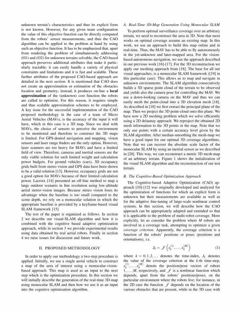
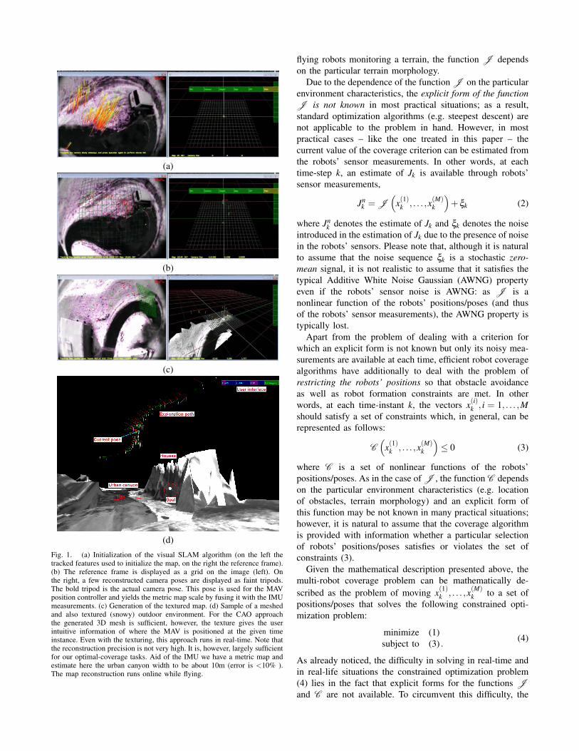
To perform optimal surveillance coverage over an arbitraryterrain, we need to reconstruct the area in 3D. Note that mostworks on optimal coverage assume an existing map. In thiswork, we use an approach to build this map online and inreal-time. Thus, the MAV has to be able to fly autonomouslyin the yet-unknown and later-mapped area. For the vision-based autonomous navigation, we use the approach describedin our previous work [16]-[17]. For the 3D reconstruction weapply our meshing approach from [18]. The base for all ourvisual approaches, is a monocular SLAM framework ([19] inthis particular case). This allows us to map and navigate inunknown environments. The SLAM algorithm consecutivelybuilds a 3D sparse point cloud of the terrain to be observedand yields also the camera pose for controlling the MAV. Weuse a down-looking camera on the MAV and thus we caneasily mesh the point-cloud into a 3D elevation mesh [18].As described in [18] we first extract the principal plane of themap. Then we project the 3D point-cloud onto this plane. Wehave now a 2D meshing problem which we solve efficientlyusing a 2D delaunay approach. We reproject the obtained 2Dmesh information to the 3D points in the map. Note that weonly use points with a certain accuracy level given by theSLAM algorithm. After median-smoothing the mesh-map wehave a good input for our optimal 3D coverage algorithms.Note that we can recover the absolute scale factor of themonocular SLAM by using an inertial sensor as we describedin [20]. This way, we can reconstruct a metric 3D mesh-mapof an arbitrary terrain. Figure 1 shows the initialization ofthe visual SLAM algorithm and the reconstruction of our testterrain.
B. The Cognitive-Based Optimization Approach
The Cognitive-based Adaptive Optimization (CAO) ap-proach [10]-[12] was originally developed and analyzed forthe optimization of functions for which an explicit form isunknown but their measurements are available as well asfor the adaptive fine-tuning of large-scale nonlinear controlsystems. In this section, we will describe how the CAOapproach can be appropriately adapted and extended so thatit is applicable to the problem of multi-robot coverage. Moreexplicitly, let us consider the problem where M robots areinvolved in a coverage task, attempting to optimize a givencoverage criterion. Apparently, the coverage criterion is afunction of the robots’ positions or poses (positions andorientations), i.e.
Jk = J(
x(1)k , . . . ,x(M)k
)(1)
where k = 0,1,2, . . . denotes the time-index, Jk denotesthe value of the coverage criterion at the k-th time-step,x(1)k , . . . ,x(M)
k denote the position/pose vectors of robots1, . . . ,M, respectively, and J is a nonlinear function whichdepends, apart from the robots’ positions/poses, on theparticular environment where the robots live; for instance, inthe 2D case the function J depends on the location of thevarious obstacles that are present, while in the 3D case with
(a)
(b)
(c)
(d)Fig. 1. (a) Initialization of the visual SLAM algorithm (on the left thetracked features used to initialize the map, on the right the reference frame).(b) The reference frame is displayed as a grid on the image (left). Onthe right, a few reconstructed camera poses are displayed as faint tripods.The bold tripod is the actual camera pose. This pose is used for the MAVposition controller and yields the metric map scale by fusing it with the IMUmeasurements. (c) Generation of the textured map. (d) Sample of a meshedand also textured (snowy) outdoor environment. For the CAO approachthe generated 3D mesh is sufficient, however, the texture gives the userintuitive information of where the MAV is positioned at the given timeinstance. Even with the texturing, this approach runs in real-time. Note thatthe reconstruction precision is not very high. It is, however, largely sufficientfor our optimal-coverage tasks. Aid of the IMU we have a metric map andestimate here the urban canyon width to be about 10m (error is <10% ).The map reconstruction runs online while flying.
flying robots monitoring a terrain, the function J dependson the particular terrain morphology.
Due to the dependence of the function J on the particularenvironment characteristics, the explicit form of the functionJ is not known in most practical situations; as a result,standard optimization algorithms (e.g. steepest descent) arenot applicable to the problem in hand. However, in mostpractical cases – like the one treated in this paper – thecurrent value of the coverage criterion can be estimated fromthe robots’ sensor measurements. In other words, at eachtime-step k, an estimate of Jk is available through robots’sensor measurements,
Jnk = J
(x(1)k , . . . ,x(M)
k
)+ξk (2)
where Jnk denotes the estimate of Jk and ξk denotes the noise
introduced in the estimation of Jk due to the presence of noisein the robots’ sensors. Please note that, although it is naturalto assume that the noise sequence ξk is a stochastic zero-mean signal, it is not realistic to assume that it satisfies thetypical Additive White Noise Gaussian (AWNG) propertyeven if the robots’ sensor noise is AWNG: as J is anonlinear function of the robots’ positions/poses (and thusof the robots’ sensor measurements), the AWNG property istypically lost.
Apart from the problem of dealing with a criterion forwhich an explicit form is not known but only its noisy mea-surements are available at each time, efficient robot coveragealgorithms have additionally to deal with the problem ofrestricting the robots’ positions so that obstacle avoidanceas well as robot formation constraints are met. In otherwords, at each time-instant k, the vectors x(i)k , i = 1, . . . ,Mshould satisfy a set of constraints which, in general, can berepresented as follows:
C(
x(1)k , . . . ,x(M)k
)≤ 0 (3)
where C is a set of nonlinear functions of the robots’positions/poses. As in the case of J , the function C dependson the particular environment characteristics (e.g. locationof obstacles, terrain morphology) and an explicit form ofthis function may be not known in many practical situations;however, it is natural to assume that the coverage algorithmis provided with information whether a particular selectionof robots’ positions/poses satisfies or violates the set ofconstraints (3).
Given the mathematical description presented above, themulti-robot coverage problem can be mathematically de-scribed as the problem of moving x(1)k , . . . ,x(M)
k to a set ofpositions/poses that solves the following constrained opti-mization problem:
minimize (1)subject to (3) . (4)
As already noticed, the difficulty in solving in real-time andin real-life situations the constrained optimization problem(4) lies in the fact that explicit forms for the functions Jand C are not available. To circumvent this difficulty, the

CAO approach, appropriately modified to be applicable tothe problem in hand, is adopted. This algorithm is capableof efficiently dealing with optimization problems for whichthe explicit forms of the objective function and constraintsare not known, but noisy measurements/estimates of thesefunctions are available at each time-step. More details abouthow the CAO approach is applied to the multi-robot coverageproblem described above can be found in [1]- [21]. In thespecific 3D case studied here the problem can be formulatedas following.
Consider a team of M flying robots that is deployed tomonitor an unknown terrain T . Let z = Φ(x,y) denote theunknown height of the terrain at the point (x,y) and assumefor simplicity that the terrain T is rectangular along the(x,y)-axes, i.e. xmin ≤ x ≤ xmax,ymin ≤ y ≤ ymax. Let P ={x(i)}M
i=1 denote the configuration of the robot team, wherex(i) denotes the position/pose of the i-th robot.
Given a particular team configuration P , let V denotethe visible area of the terrain, i.e. V consists of all points(x,y,Φ(x,y))∈T that are visible from the robots. Given therobots’ sensor capabilities, a point (x,y,Φ(x,y)) of the terrainis said to be visible if there exists at least one robot so that• the robot and the point (x,y,Φ(x,y)) are connected by
a line-of-sight;• the robot and the point (x,y,Φ(x,y)) are at a distance
smaller than a given threshold value (defined as themaximum distance the robot’s sensor can “see”).
Apparently, the main objective for the robot team is tomaximize the visible area V . However, this cannot be theonly objective for the robot team in a coverage task: tryingto maximize the visible area will simply force the robotsto “climb” as high as1 possible. In parallel to maximizingthe visible area, the robot team should make sure that itminimizes the average distance between each of the robotsand the terrain subarea the particular robot is responsiblefor, where the terrain subarea a particular robot is responsiblefor, is defined as follows: given a team configuration P ,the subarea of the terrain the i-th robot is responsible for isdefined as the part of the terrain that (a) is visible by thei-th robot and (b) each point in this subarea is closer to thei-th robot than any other robot of the team. This second,and parallel to maximizing visibility, objective for the robotteam is necessary for two practical reasons: (a) firstly, thecloser is the robot to a point in the terrain the better is,in general, its sensing ability to monitor this point and (b)secondly, in many multi-robot coverage applications there isthe necessity of being able to intervene as fast as possiblein any of the points of the terrain with at least one robot.Having in mind that the robot team has to successfully meetthe two above-described objectives, we define the followingcombined objective function the robot team has to minimize:
J(P) =∫
q∈Vmin
i∈{1,...,M}
∣∣∣x(i)−q∣∣∣2 dq+K
∫q∈T −V
dq (5)
1Note also that in the case where there are no limits for the robot’smaximum height and the maximum sensing distance, it suffices to have asingle robot at a very high position to monitor the whole terrain.
where K is a large user-defined positive constant. The firstof the terms in the above equation is related to the secondobjective (minimize the average distance between the robotsand the subarea they are responsible for) and the second termis related to the invisible area in the terrain (
∫q∈T −V dq is
the total part of the terrain that is not visible by any of therobots). The positive constant K is used to make sure thatboth objectives are met. To see this, consider the case whereK = 0, in which case we will have that the robots, in theirattempt to minimize their average distance to the subareathey are responsible for, may also seek to minimize the totalvisible area. On the other hand, in case where the first of theterms in (5) is absent, we will have the situation mentionedabove where the robots in their attempt to maximize thevisible area will have to “climb” as high as they are allowedto.
It has to be emphasized that the positive constant K shouldbe chosen sufficiently large so that the second term in (5)dominates the first term unless no or a negligible part of theterrain remains invisible. In this way, minimization of (5) isequivalent to firstly making sure that all – or almost all –of the terrain is visible and then to locate the robots so thattheir average distance to the subarea they are responsible foris minimized.
A large choice for the positive term K plays another crucialrole for the practical implementation of the CAO algorithmin multi-robot coverage applications: the problem with theperformance index defined in (5) is that its second term∫
q∈T −V dq cannot be, in general, computed in practice; asthis term involves the part of the terrain that is not currentlyvisible, its computation requires that the geometry this part isknown or equivalently, as the invisible part changes with theevolution of the team’s configuration, that the whole terrainis known. To overcome this problem, instead of minimizing(5) the following performance index is actually minimizedby the CAO approach:
J(P) =∫
q∈Vmin
i∈{1,...,M}
∣∣∣x(i)−q∣∣∣2 dq
+K∫(x,y,φ(x,y))∈T −V
I (x,y)dxdy (6)
where I (q) denotes the indicator function that is equal to1 if the point (x,y,φ(x,y)) belongs to the invisible area ofthe terrain and is zero, otherwise. In other words, in the costcriterion J(P) and for the whole invisible area, the unknownterrain points (x,y,φ(x,y)) are replaced by (x,y,1), i.e. J(P)assumes that the whole invisible area is a flat subarea.
It is not difficult for someone to see that the replacementof the cost criterion (5) by the criterion (6) has a negligibleimplication in the team’s performance: as a large choice forK corresponds to firstly making sure that the whole terrain isvisible and then to minimizing the average distance betweenthe robots and their responsible subareas, minimizing eitherof criteria (5) or (6) is essentially the same.
An efficient trajectory generation algorithm for optimalcoverage – i.e. for minimization of the cost criteria (5) or(6) – must make sure that the physical constraints are also
met throughout the whole multi-robot coverage application.Such physical constraints include, but are not limited to, thefollowing ones:• The robots remain within the terrain’s limits, i.e. they
remain within [xmin,xmax] and [ymin,ymax] in the x− andy-axes, respectively.
• The robots satisfy a maximum height requirement whilethey do not “hit” the terrain, i.e. they remain within[Φ(x,y) + d,zmax] along the z-axis, where d denotesthe minimum safety distance (along the z-axis) therobots’ should be from the terrain and zmax denotes themaximum allowable height for the robots.
• The robots do not come closer on to each other than aminimum allowable safety distance dr.
It is not difficult for someone to see that all the aboveconstraints can be easily cast in the form (3) and thus canbe handled by the CAO algorithm.
III. EXPERIMENTAL RESULTSTo validate our approach in a realistic environment, we
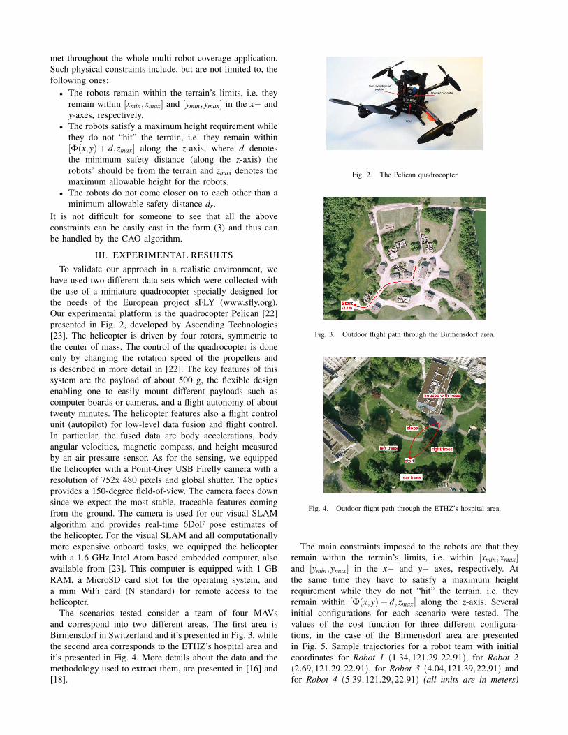
have used two different data sets which were collected withthe use of a miniature quadrocopter specially designed forthe needs of the European project sFLY (www.sfly.org).Our experimental platform is the quadrocopter Pelican [22]presented in Fig. 2, developed by Ascending Technologies[23]. The helicopter is driven by four rotors, symmetric tothe center of mass. The control of the quadrocopter is doneonly by changing the rotation speed of the propellers andis described in more detail in [22]. The key features of thissystem are the payload of about 500 g, the flexible designenabling one to easily mount different payloads such ascomputer boards or cameras, and a flight autonomy of abouttwenty minutes. The helicopter features also a flight controlunit (autopilot) for low-level data fusion and flight control.In particular, the fused data are body accelerations, bodyangular velocities, magnetic compass, and height measuredby an air pressure sensor. As for the sensing, we equippedthe helicopter with a Point-Grey USB Firefly camera with aresolution of 752x 480 pixels and global shutter. The opticsprovides a 150-degree field-of-view. The camera faces downsince we expect the most stable, traceable features comingfrom the ground. The camera is used for our visual SLAMalgorithm and provides real-time 6DoF pose estimates ofthe helicopter. For the visual SLAM and all computationallymore expensive onboard tasks, we equipped the helicopterwith a 1.6 GHz Intel Atom based embedded computer, alsoavailable from [23]. This computer is equipped with 1 GBRAM, a MicroSD card slot for the operating system, anda mini WiFi card (N standard) for remote access to thehelicopter.
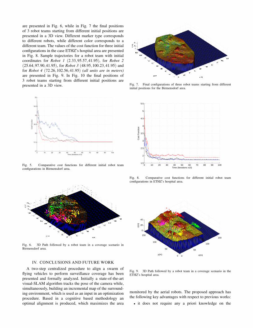
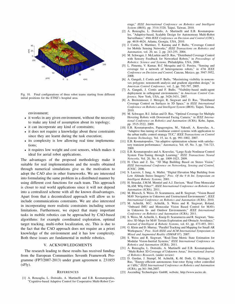
The scenarios tested consider a team of four MAVsand correspond into two different areas. The first area isBirmensdorf in Switzerland and it’s presented in Fig. 3, whilethe second area corresponds to the ETHZ’s hospital area andit’s presented in Fig. 4. More details about the data and themethodology used to extract them, are presented in [16] and[18].
Fig. 2. The Pelican quadrocopter
Fig. 3. Outdoor flight path through the Birmensdorf area.
Fig. 4. Outdoor flight path through the ETHZ’s hospital area.
The main constraints imposed to the robots are that theyremain within the terrain’s limits, i.e. within [xmin,xmax]and [ymin,ymax] in the x− and y− axes, respectively. Atthe same time they have to satisfy a maximum heightrequirement while they do not “hit” the terrain, i.e. theyremain within [Φ(x,y) + d,zmax] along the z-axis. Severalinitial configurations for each scenario were tested. Thevalues of the cost function for three different configura-tions, in the case of the Birmensdorf area are presentedin Fig. 5. Sample trajectories for a robot team with initialcoordinates for Robot 1 (1.34,121.29,22.91), for Robot 2(2.69,121.29,22.91), for Robot 3 (4.04,121.39,22.91) andfor Robot 4 (5.39,121.29,22.91) (all units are in meters)
are presented in Fig. 6, while in Fig. 7 the final positionsof 3 robot teams starting from different initial positions arepresented in a 3D view. Different marker type correspondsto different robots, while different color corresponds to adifferent team. The values of the cost function for three initialconfigurations in the case ETHZ’s hospital area are presentedin Fig. 8. Sample trajectories for a robot team with initialcoordinates for Robot 1 (2.33,95.57,41.95), for Robot 2(25.64,97.90,41.95), for Robot 3 (48.95,100.23,41.95) andfor Robot 4 (72.26,102.56,41.95) (all units are in meters)are presented in Fig. 9. In Fig. 10 the final positions of3 robot teams starting from different initial positions arepresented in a 3D view.
0 10 20 30 40 50 60 70 80 90 10017
17.5
18
18.5
19
19.5
20
Time (Iterations x10)
Cos
t Fun
ctio
n
Fig. 5. Comparative cost functions for different initial robot teamconfigurations in Birmensdorf area.
Fig. 6. 3D Path followed by a robot team in a coverage scenario inBirmensdorf area.
IV. CONCLUSIONS AND FUTURE WORK
A two-step centralized procedure to align a swarm offlying vehicles to perform surveillance coverage has beenpresented and formally analyzed. Initially a state-of-the-artvisual-SLAM algorithm tracks the pose of the camera while,simultaneously, building an incremental map of the surround-ing environment, which is used as an input in an optimizationprocedure. Based in a cognitive based methodology anoptimal alignment is produced, which maximizes the area
Fig. 7. Final configurations of three robot teams starting from differentinitial positions for the Birmensdorf area.
0 10 20 30 40 50 60 70 80 90 1001.5
2
2.5
3
3.5
4
4.5
5
5.5
Time (Iterations x10)
Cos
t Fun
ctio
n
Fig. 8. Comparative cost functions for different initial robot teamconfigurations in ETHZ’s hospital area.
0
50
100
150
0
50
100
150
0
20
40
x(m)y(m)
z(m
)
Fig. 9. 3D Path followed by a robot team in a coverage scenario in theETHZ’s hospital area.
monitored by the aerial robots. The proposed approach hasthe following key advantages with respect to previous works:
• it does not require any a priori knowledge on the
0
50
100
150
0
50
100
150
0
20
40
x(m)y(m)
z(m
)
Fig. 10. Final configurations of three robot teams starting from differentinitial positions for the ETHZ’s hospital area.
environment;• it works in any given environment, without the necessity
to make any kind of assumption about its topology;• it can incorporate any kind of constraints;• it does not require a knowledge about these constraints
since they are learnt during the task execution;• its complexity is low allowing real time implementa-
tions;• it requires low weight and cost sensors, which makes it
ideal for aerial robot applications.The advantages of the proposed methodology make itsuitable for real implementations and the results obtainedthrough numerical simulations give us the motivation toadopt the CAO also in other frameworks. We are interestedinto formulating the same problem in a distributed manner byusing different cost functions for each team. This approachis closer to real world applications since it will not dependinto a centralized scheme with all the known disadvantages.Apart from that a decentralized approach will allow us toinclude communications constraints. We are also interestedin incorporating more realistic constraints including sensorlimitations. Furthermore, we expect that many importanttasks in mobile robotics can be approached by CAO-basedalgorithms: for example coordinated exploration, optimaltarget tracking, multi-robot localization, etc. This is due tothe fact that the CAO approach does not require an a prioriknowledge of the environment and it has low complexity.Both these issues are fundamental in mobile robotics.
V. ACKNOWLEDGMENTS
The research leading to these results has received fundingfrom the European Communities Seventh Framework Pro-gramme (FP7/2007-2013) under grant agreement n. 231855(sFly).
REFERENCES
[1] A. Renzaglia, L. Doitsidis, A. Martinelli and E.B. Kosmatopoulos,”Cognitive-based Adaptive Control for Cooperative Multi-Robot Cov-
erage,” IEEE International Conference on Robotics and IntelligentSystem (IROS), pp. 3314-3320, Taipei, Taiwan, 2010.
[2] A. Renzaglia, L. Doitsidis, A. Martinelli and E.B. Kosmatopou-los, ”Adaptive-based, Scalable Design for Autonomous Multi-RobotSurveillance,” 49th IEEE Conference on Decision and Control (CDC),pp. 4618-4624, Atlanta, Georgia, USA, 2010.
[3] J. Cortes, S. Martınez, T. Karatas and F. Bullo, “Coverage Controlfor Mobile Sensing Networks,” IEEE Transactions on Robotics andAutomation, vol. 20, no. 2, pp. 243-255, 2004.
[4] M. Schwager, J. McLurkin and D. Rus, “Distributed Coverage Controlwith Sensory Feedback for Networked Robots,” in Proceedings ofRobotics: Science and Systems, Philadelphia, USA, 2006.
[5] L. Pimenta, V. Kumar, R.C Mesquita and G. Pereira, “Sensing andcoverage for a network of heterogeneous robots,” in 47th IEEEConference on Decision and Control, Cancun, Mexico, pp. 3947-3952,2008.
[6] A. Ganguli, J. Cortes and F. Bullo, “Maximizing visibility in noncon-vex polygons: nonsmooth analysis and gradient algorithm design,” inAmerican Control Conference, vol. 2, pp. 792-797, 2005.
[7] A. Ganguli, J. Cortes and F. Bullo, “Visibility-based multi-agentdeployment in orthogonal environments,” in American Control Con-ference, New York, USA, pp. 3426-3431, 2007.
[8] A. Breitenmoser, J. Metzger, R. Siegwart and D. Rus, ”DistributedCoverage Control on Surfaces in 3D Space,” in IEEE InternationalConference on Robotics and Intelligent System (IROS), Taipei, Taiwan,2010.
[9] M. Schwager, B.J. Julian and D. Rus, “Optimal Coverage for MultipleHovering Robots with Downward Facing Camera,“ in IEEE Interna-tional Conference on Robotics and Automation (ICRA), Kobe, Japan,pp. 3515-3522, 2009.
[10] E.B. Kosmatopoulos, Papageorgiou, M., Vakouli, A. Kouvelas, A.,“Adaptive fine-tuning of nonlinear control systems with application tothe urban traffic control strategy TUC,” IEEE Transactions on ControlSystems Technology, Vol. 15, no. 6, pp. 991-1002, 2007.
[11] E.B. Kosmatopoulos, “An adaptive optimization scheme with satisfac-tory transient performance,” Automatica, Vol. 45, No. 3, pp. 716-723,2009.
[12] E.B. Kosmatopoulos and A. Kouvelas, “Large-Scale Nonlinear ControlSystem Fine-Tuning through Learning,” IEEE Transactions NeuralNetworks, Vol. 20, No. 6, pp. 1009-1023, 2009.
[13] H. Chen and Z. Xu, “3D Map Building Based on Stereo Vision,”IEEE International Conference on Networking, Sensing and Control,ICNSC, 2006.
[14] S. Lacroix, I. Jung, A. Mallet, “Digital Elevation Map Building fromLow Altitude Stereo Imagery,” Proc. Of the 9 th Int. Symposium onIntelligent Robotic Systems, 2001.
[15] H. Strasdat, J.M.M. Montiel and A.J. Davison, “Real-Time MonocularSLAM: Why Filter?”, IEEE International Conference on Robotics andAutomation (ICRA), 2011.
[16] M. Bloesch, S. Weiss, D. Scaramuzza, and R. Siegwart, “Vision BasedMAV Navigation in Unknown and Unstructured Environments”, IEEEInternational Conference on Robotics and Automation (ICRA), 2010.
[17] M. Achtelik, M.C. Achtelik, S. Weiss and R. Siegwart, Roland,“Onboard IMU and Monocular Vision Based Control for MAVsin Unknown In- and Outdoor Environments,” IEEE InternationalConference on Robotics and Automation (ICRA), 2011.
[18] S. Weiss, M. Achtelik, L. Kneip D. Scaramuzza and R. Siegwart, “Intu-itive 3D Maps for MAV Terrain Exploration and Obstacle Avoidance,”Journal of Intelligent & Robotic Systems, vol. 61, pp. 473-493, 2011.
[19] G. Klein and D. Murray, “Parallel Tracking and Mapping for Small ARWorkspaces,” Proc. Sixth IEEE and ACM International Symposium onMixed and Augmented Reality (ISMAR’07), 2007.
[20] S. Weiss and R. Siegwart, “Real-Time Metric State Estimation forModular Vision-Inertial Systems,” IEEE International Conference onRobotics and Automation (ICRA), 2011.
[21] A. Renzaglia, L. Doitsidis, A. Martinelli and E.B. Kosmatopoulos,”Multi-Robot 3D Coverage of Unknown Areas,” International Journalof Robotics Research, (under review)
[22] D. Gurdan, J. Stumpf, M. Achtelik, K.-M. Doth, G. Hirzinger, D.Rus, ”Energy-efficient autonomous four-rotor flying robot controlledat 1 kHz,” IEEE International Conference on Robotics and Automation(ICRA), pp.361-366,2007.
[23] Ascending Technologies GmbH, website, http://www.asctec.de.
Related Documents


![EGO-SLAM: A Robust Monocular SLAM for …arXiv:1707.05564v2 [cs.CV] 17 Nov 2018 In this paper, we investigate the monocular SLAM prob-lem with a special emphasis on EGOcentric videos,](https://static.cupdf.com/doc/110x72/5fe2bff5b533fd76167f3e75/ego-slam-a-robust-monocular-slam-for-arxiv170705564v2-cscv-17-nov-2018-in.jpg)

![EGO-SLAM: A Robust Monocular SLAM for Egocentric Videossuvam/rslam_wacv19_camera_ready.pdf · Figure 1: Incremental nature of state of the art SLAM [32,9,19] as well as SFM [56,55,50]](https://static.cupdf.com/doc/110x72/601f57958b217666bc405b71/ego-slam-a-robust-monocular-slam-for-egocentric-suvamrslamwacv19camerareadypdf.jpg)