71 CHAPTER-5 CEMENTING Oil well cementing falls into three categories. -primary cementing job on a casing string -squeeze cementing -plugs Primary Cementing: Casing strings are usually cemented : -to isolate troublesome behind the casing from deeper formations to be drilled, -to isolate high-pressure formations below the casing from the weaker shallow zones behind the casing, -to isolate producing zones from water bearing sands. The cement is normally placed behind the casing in a single or multi-stage technique. The single stage technique pumps cement down the casing and up to annulus. The heavier cement in the annulus is prevented from U-tubing by back- pressure valves in the bottom of the casing string. The initial stage of multi- stage job is usually planned as if it were a single stage effort. Cement is pumped down and up to annulus. The next stage is pumped through a special port collar at the desired location up to annulus. The port is opened after the initial stage is cemented.

Welcome message from author
This document is posted to help you gain knowledge. Please leave a comment to let me know what you think about it! Share it to your friends and learn new things together.
Transcript

71
CHAPTER-5
CEMENTING
Oil well cementing falls into three categories.
-primary cementing job on a casing string
-squeeze cementing
-plugs
Primary Cementing:
Casing strings are usually cemented :
-to isolate troublesome behind the casing from deeper formations to be drilled,
-to isolate high-pressure formations below the casing from the weaker shallow
zones behind the casing,
-to isolate producing zones from water bearing sands.
The cement is normally placed behind the casing in a single or multi-stage
technique. The single stage technique pumps cement down the casing and up to
annulus. The heavier cement in the annulus is prevented from U-tubing by back-
pressure valves in the bottom of the casing string. The initial stage of multi-
stage job is usually planned as if it were a single stage effort. Cement is pumped
down and up to annulus. The next stage is pumped through a special port collar at
the desired location up to annulus. The port is opened after the initial stage is
cemented.
72
Squeeze Cementing:
A common method for repairing faulty primary casing jobs or performing
remedial operations on the hole is squeeze cementing. Major applications:
-supplement a faulty primary casing cement job,
-reduce water-oil, water-gas and gas-oil ratio
-repair casing leaks,
-stop lost circulation in an open hole while drilling
-bring a well under control.
Placement techniques and slurry design are important considerations
squeeze operations. Supplementing a faulty or ineffective primary casing cement
job is the most prominent application for squeeze cementing.
Cement Characteristics
The cement slurry pumped into oil and gas wells includes cement, special
additives and water. Portland cement is most commonly used. The additives are
used to control characteristics such as thickening time, density and compressive
strength. Water is an important agent in the cementing.
Portland Cement:
Portland cement is manufactured by calcining limestone, clay, shale, and
slag together at 2000-2600 oF in a rotary kiln. The resulting material, clinker, is
cooled and inters ground with small percentages of gypsum to form Portland
cement. In addition to the raw materials, other components such as sand, bauxite,

73
and iron oxide may be added to adjust the chemical composition of the clinker for
the different types of Portland cement. The principal components of the finished
Portland cement are lime, silica, alumina, and iron. Each component affects the
slurry in a different manner. When water is added to cement, setting and
hardening reactions begin immediately. The chemical compounds in the cement
undergo hydration and re-crystallization, resulting in a set product. The API has
established a classification system for cements used in oil and gas operations.
Slurry Features
Variables involved in the design of the slurry include:
yield, density, mix water, thickening time, compressive strength, fluid loss
and downhole temperature.
-The yield of the cement in cubic ft per sack, is the volume of space that will
be occupied by the dry cement, water and additives when the slurry is mixed
according to design specifications. A major factor affecting the slurry yield is
the density, since water must be added in significant volumes to achieve low
weight cements that will not fracture shallow, weak zones.
-The density of cement is an important design criterion. It must be sufficient
to prevent kick and blow-outs yet it should not cause lost circulation.
-The mixing water requirements will vary, depending primarily on cement class
and slurry density. Most cement jobs use well site water. Quality of mixing water
is an important parameter in cement planning. The hydration and curing of the

74
slurry will react differently with varying amounts of salt, calcium, or magnesium
the mix water.
-Thickening time is the amount of time that cement remains pumpable with
reasonable pressures. This is the perhaps the most critical property in the
displacement process. Factors affecting the thickening time include cement
composition and temperature. The compressive strength is measured in pounds
per square inch. A 500psi minimum compressive strength is generally
recommended before drilling operations resume, but higher strengths are
preferred.
-Temperature affects the compressive strength of the cement. Higher
temperatures reduce the time for the cement slurry to reach some compressive
levels. However, at temperatures above 230 oC, cement strength begins to
decrease.
-Fluid loss is the water lost from the slurry to the formation during slurry
placement operations. If a large volume of water is lost, the slurry becomes too
viscous or dense to pump. Neat cement, or cement with no special additives has
a fluid loss rate in excess of 1000 cc/30 min.
0-200 cc/30 min Good control
200-500 cc/30 min Moderate control
500-1000 cc/30 min Fair control
Over 1000 cc/30 min No control
75
Cement Additives
Neat slurry is a mixture of water and cement only. Special chemicals are
often added to the slurry to achieve some desired purposes. These additives are:
Accelarators, retarders, density adjuster, dispersants, fluid loss additives
Accelarators: Most operators wait for cement to reach a minimum of 500 psi
compressive strength before resuming operations. At temperatures below 100 oF
common cement may require a day or two to develop 500 psi strengths.
Accelerators are useful at reducing the amount of waiting-on-cement (WOC)
time. Low concentration of cement accelerators, usually 2-4 % by weight of
cement, shorten the setting time of cement and promote rapid strength
development. Calcium chloride is perhaps the most commonly used chemical for
this purpose.
Retarders: High formation temperatures associated with increased well depths
necessitate the use of chemicals that retard the setting time of the cement; i.e.
increase the pumping time. The most common retarder may be calcium
lignosulfonate. Its effectiveness is limited in temperatures above 200 oF. Other
retarders such as carboxymethyl-hydoxyethylcellulose, can be used to about 240
oF.
Density Adjusters: High formation pressures for neat slurry densities require
additions in cement density. Formations with low fracture gradients require
reductions in cement weight. Dispersants as an additive can increase slurry
76
densities to 17.5 ppg due to their effect on viscosity. Adding more water to the
slurry and adding materials to prevent solid separation achieve density
reductions.
Dispersants: Dispersants provide several beneficial features for the slurry.
-reduce slurry viscosity
-allow slurry turbulence at lower pump rates
-assist in providing fluid loss control for densified slurries
Fluid Loss Additives: Fluid loss agents are used in cement slurries for the
following reasons:
-minimize cement dehydration in the annulus
-reduce gas migration
-improve bonding
-minimize formation damage.
Slurry Design
A well plan is not complete until the cement slurry has been designed.
Major aspects of the design are as follows:
-Volumetric requirements for the casing and annulus
-cement
-mixing water
-density selection

77
Calculation of slurry density or “weight” usually expressed in pounds per gallon, is
based on the following equation.
Slurry weight = (lb cement + lb water + lb addit.) / (gal cement + gal water
+ gal addit.)
Cement has a bulk density of 94 lb/cu ft, an absolute density of 94/0.48 = 195.8
lb/cu ft and an specific gravity of 195.8/62.4 = 3.14.
The absolute volume of all solid constituents must be calculated in gallons, where:
Absolute Volume, gal = (lb of material) / (8.34 lb/gal x spec. grav. of
material)
The volume of slurry to be realized from 1 sack of cement when mixed with a
specified amount of water and possibly other additives is called the yield. The
yield in cubic feet per sack of cement is :
Yield = (gal cement + gal water + gal additive) / 7.48 gal/cu ft
Example 4-1
Calculate the weight, percent mix and yield or set volume of a slurry given?
Water-cement ratio = 5.5 gal/sx
Spec. Grav. of cement = 3.14
1 sx = 1 cu ft = 94 lb
Density of water = 8.34 ppg
Solution:
78
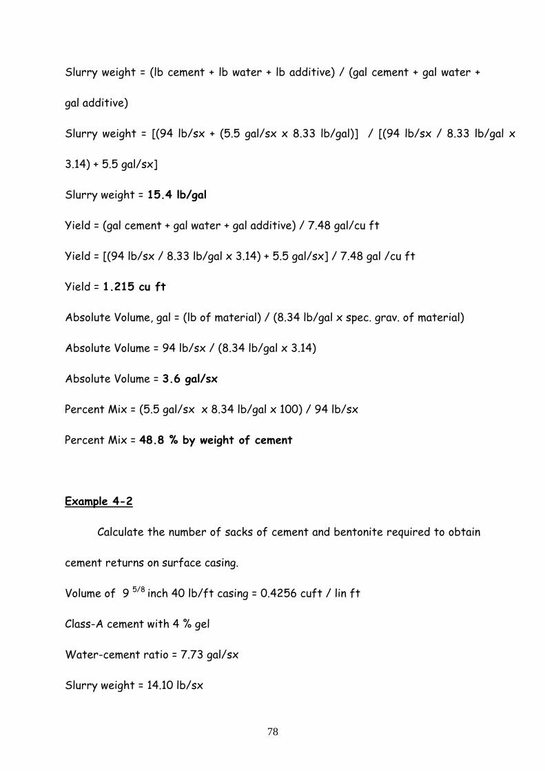
Slurry weight = (lb cement + lb water + lb additive) / (gal cement + gal water +
gal additive)
Slurry weight = [(94 lb/sx + (5.5 gal/sx x 8.33 lb/gal)] / [(94 lb/sx / 8.33 lb/gal x
3.14) + 5.5 gal/sx]
Slurry weight = 15.4 lb/gal
Yield = (gal cement + gal water + gal additive) / 7.48 gal/cu ft
Yield = [(94 lb/sx / 8.33 lb/gal x 3.14) + 5.5 gal/sx] / 7.48 gal /cu ft
Yield = 1.215 cu ft
Absolute Volume, gal = (lb of material) / (8.34 lb/gal x spec. grav. of material)
Absolute Volume = 94 lb/sx / (8.34 lb/gal x 3.14)
Absolute Volume = 3.6 gal/sx
Percent Mix = (5.5 gal/sx x 8.34 lb/gal x 100) / 94 lb/sx
Percent Mix = 48.8 % by weight of cement
Example 4-2
Calculate the number of sacks of cement and bentonite required to obtain
cement returns on surface casing.
Volume of 9 5/8 inch 40 lb/ft casing = 0.4256 cuft / lin ft
Class-A cement with 4 % gel
Water-cement ratio = 7.73 gal/sx
Slurry weight = 14.10 lb/sx
79
Casing to be landed at 1400 ft
Excess cement required = 35 %
Solution:
Cement left in casing = 30 ft x 0.4256 cu ft / ft
Cement left in casing = 12.77 cu ft
Cement required to fill annulus = 1400 ft x 0.3469 cu ft / ft x 1.35
Cement required to fill annulus = 655.64 cu ft
Total Cement required = 12.77 cu ft + 655.64 cu ft = 668.41 cu ft
Sacks of cement required = 668.41 / 1.536 = 435 sx
Pounds of cement = 435 sx x 94 lb/sx = 40890 lb
Bentonite required = 40890 x 4/100 = 1636 lb or 163.6 sx
Cement planning involves evaluating and selecting equipment to be used with the
cementing process. The down-hole equipment includes shoes and collars that are run as
integral sections of the casing string. In addition, many cementing aids attached to the
exterior of the pipe may be used, i.e., centralisers, scratchers and cement baskets.
Casing Shoe: A casing shoe is a short, heavy walled pipe run on the bottom of the
casing string. It has a rounded “nose” to guide the casing into the hole. The shoe is
screwed on the casing and generally is “glued” with a thread-locking compound. Casing
shoes are generally available in three types.

80
i) guide shoe; ii) float shoe and iii) differential fill shoe.
Figure 4-1 Guide shoe (Courtesy World Oil’s Cementing Book)
Figure 4-2 Float Collar (Courtesy World Oil’s Cementing Handbook)
A guide shoe contains an orifice through the centre that allows mud to pass
freely. A float shoe contains a back pressure valve that prevents mud from flowing into
81
the casing from the bottom yet allows fluid to be pumped through the shoe. Float valve
prevents surface casing pressure resulting from cement U-tubing. The driller must fill,
or partially fill, the casing with mud periodically to prevent casing collapse as the
annulus hydrostatic pressure increases with depth. Differential fill shoe are similar in
concept to float shoes.
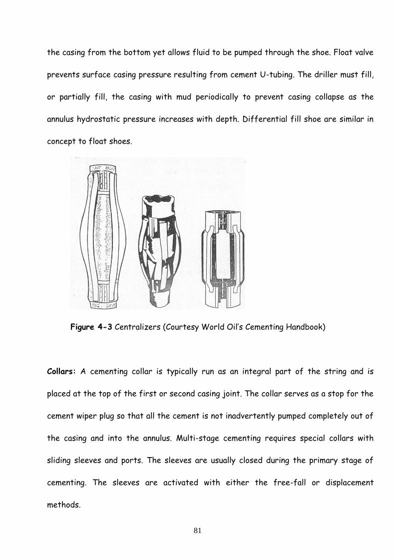
Figure 4-3 Centralizers (Courtesy World Oil’s Cementing Handbook)
Collars: A cementing collar is typically run as an integral part of the string and is
placed at the top of the first or second casing joint. The collar serves as a stop for the
cement wiper plug so that all the cement is not inadvertently pumped completely out of
the casing and into the annulus. Multi-stage cementing requires special collars with
sliding sleeves and ports. The sleeves are usually closed during the primary stage of
cementing. The sleeves are activated with either the free-fall or displacement
methods.

82
Centralizers: Centralizers are placed on the exterior of the casing string to provide
stand-off distance between the well bore and the pipe in an effort to assist in
attaining cement encirclement of the pipe. Numerous types of centralizers are
available. The bow spring type is most common.
Scratchers: To achieve an effective cement job, the slurry must bond to the
formation. Scratchers assist by scraping and scratching the mud cake on the formation
to promote bonding to the virgin formation.
Cement Baskets: Cement baskets provide support for the column of cement while it
cures, or hardens. The baskets are often placed above lost circulation zones that
cannot support a full column of cement.
Plugs: The cement slurry is normally separated from the mud column by plugs that
minimise interface contamination. The bottom plug has a diaphragm that is ruptured
with pump pressure after it seats on the collar or shoe. The top plug has a solid
aluminium insert. The plugs are mounted in a cementing head at the top of the casing.
83
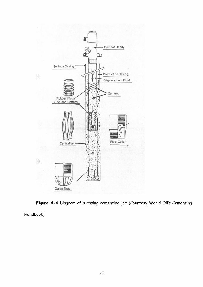
Displacement Process
Pumping the cement into the annulus is an important to the successful cementing
program as the slurry design. The displacement rate affects the flow regime in the
annulus. High flow rates convert the flow regime from laminar to turbulent. Although
annular turbulent flow is not desirable in most drilling operations, it is desirable in
cementing operations because it erodes the mud cake on the formation. Contamination
of the interface between the mud and cement is a problem that can reduce the
effectiveness of the cement job. This problem can be controlled by separating the mud
and cement with a spacer fluid (Figure 4-4, 4-5).
Primary Cementing Technique
Primary cementing operations are usually conducted in single or multiple stages.
The single stage method has been used traditionally for conductor, surface,
intermediate and production casing strings. Procedure:
1.Drill hole to desired depth.
2.Pull drill string and run intermediate casing.
3.Circulate hole with rig pump.
4.Attach cementing head with plugs to casing.
84
Figure 4-4 Diagram of a casing cementing job (Courtesy World Oil’s Cementing
Handbook)

85
Figure 4-5 Equipment typically used to install and cement a drilling liner
(Courtesy BJ-Hughes Services)

86
Figure 4-6 Setting and cementing casing (Courtesy Oil & Gas Journal)
5.Connect lines to pump truck and cementing head.
6.Start circulation with pump track.
7.Release bottom plug.
8.Pump spacer to remove mud.
9.Mix cement and displace until all cement is mixed and in casing.
10.Release plug.
a) Release top plug for a single-step job.
b) Release bottom shut-off plug for second-stage job (Figure 4-7).
87
11.Pump until sharp pressure increase is noted on pump truck gauge, indicating top plug
has bumped.
Step 12-16 is for stage cementing.
12.Drop bomb, open ports.
13.Circulate any excess cement around the stage tool.
14.Wait at least 6 hr. for cement to gain initial strength.
15.Mix second stage cement and displace until all cement is mixed and in casing.
16.Release top closing plug and displace until a sharp increase is noted on the pump
truck gauge, indicating the plug has bumped.
17.Release pressure to determine if single stage or stage tool is holding.
Liner and Squeeze Cementing
The liner is run on the bottom of the drill pipe with a hanger and setting tool.
Hangers are usually set mechanically or with a hydraulic action. A typical liner assembly
is given. Plugs sweep cement from the interior of the liner to the float collar. If the
primary cement job is nor successful, squeeze cementing will not be required. However,
potential problems must be considered to overcome poor primary jobs. Application for
squeeze cementing in drilling and producing operations include:
-casing shoe; -liner top
-perforation
-plug a producing zone or sections of the zone
-seal lost circulation problems.
88
Example 4-3
Assume that a 10000-ft well is in an area where the geothermal gradient is 1.8
oF/100 ft. Determine the bottom hole temperature (BHT) if the ambient temperature
is 70 oF.
Solution:
BHT = (D / 100 x G) + TA
BHT = (10000 / 100 x 1.8) + 70
BHT = 250 oF
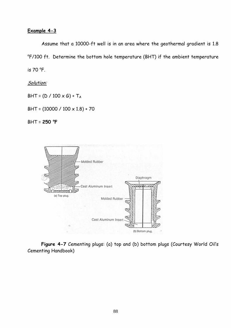
Figure 4-7 Cementing plugs: (a) top and (b) bottom plugs (Courtesy World Oil’s
Cementing Handbook)

89
Example 4-4
A cementing engineer was preparing to runcompressive strength tests on a
cement slurry prior to upcoming casing job. The following data wre available from the
logging engineer. The well had been circulated for 6 hr prior to logging.
Run No Time Diff. Btw Runs, hr Temp. oF
1 7 220
2 4.5 225
3 8 228
Estimate the bottom hole static temperatuıre (BHST) ?
Solution:
TD = time after circulation / (time of circulation + time after circulation)
Run 1, TD = 7 / (6 + 7) = 0.538
Run 2, TD = (7 + 4.5) / (6 + 7 + 4.5) = 0.657
Run 3, TD = (7 + 4.5 + 8) / (6 + 7 + 4.5 + 8) = 0.765
Plot the data and extrapolate to a BHST of 235 oF.
Figure 4-8 Estimation of BHST

90
Example 4-5
A 7 5/8 inch 39 lb/ft production casing string will be run inside 51 lb/ft, 10 ¾
surface casing set at 2000 ft. The bottom of the 9 inch hole is at 9100 ft (casing
seat). Compute the volume of casing and annulus. A 6 ½ inch x 18 inch duplex pump will
be used to pump the cement plıg against the float shoe. If the pump operates at 90 %
efficiency, how many strokes will be required? After the job was completed, the
drilling engineer at the well site observed that 1990 strokes were required to bump the
plug. What is the actual pump efficiency?
Solution:
7 5/8 inch pipe capacity = 0.2394 cu ft / lin ft; 0.0426 bbl / lin ft
7 5/8 in. x 9 inch hole annulus = 0.1247 cu ft / lin ft
7 5/8 in. x 9.85 inch annulus = 0.2148 cu ft / lin ft ; 0.0382 bbl / lin ft
Compute the pipe and annulus capacities:
7 5/8 inch pipe capacity = 910 ft x 0.0426 bbl / lin ft = 387.6 bbl
7 5/8 in. x 9 inch hole annulus = (9100 – 2000) ft x 0.0222 bbl/lin ft = 157.6 bbl
7 5/8 in. x 9.85 inch annulus = 2000 ft x 0.0382 bbl / lin ft = 76.4 bbl
The output of the 6 ½ inch x 18 inch duplex pump is obtained as:
0.2280 bbl/stroke = 100 % efficiency
0.2052 bbl/stroke = 90 % efficiency

91
Determine the pump stroke requirements to bump the plug.
387.6 bbl / (0.2052 bbl / stroke) = 1888 stroke
If the pump required 1990 strokes, determine the output.
387.6 bbl / 1990 strokes = 0.1948 bbl / stroke
Determine the actual efficiency.
(0.1948 bbl / stroke) / (0.2280 bbl / stroke) x 100 = 85.4 %
Example 4-6
A 3000 ft 13 3/8 inch surface casing is to be cemented in a 17.5 inch hole. The
1000 ft tail slurry is 14.2 lb/gal Class-A cement with 4 % gel.The remaining lead slurry
is 12.2 lb/gal Class-A cement with 16 % gel. Use 100 % volumetric wash out. Compute
the cement, water and gel requirements.
Solution:
The annulus volume is computed as:
0.6946 cu ft / lin ft x 2000 ft = 1389.2 cu ft
0.6946 cu ft / lin ft x 1000 ft = 694.6 cu ft
Accounting for 100 % wash outs:
(2000 ft lead slurry) : 1389.2 x 2 = 2778.4 cu ft
(1000 ft lead slurry) : 694.6 x 2 = 1389.2 cu ft
Lead slurry calculations are as follows:
Cement: 2778.4 cu ft / (2.55 cu ft / sx) = 1089.5 sx of cement

92
Gel: (1089.5 sx) (16 % gel) (94 lb/sx) = 16386 lb gel = 163.86 sx of gel
Water : 14.7 gal/sx x 1089.5 sx = 16015 gal = 381 bbl
Tail slurry calculations are as follows:
Cement: 1389.2 cu ft / (1.52 cu ft / sx) = 913.9 sx of cement
Gel: (913.9 sx) (4 % gel) (94 lb/sx) = 3436 lb gel = 34.4 sx of gel
Water : (913.9 sx) x 7.57 gal/sx = 6918 gal = 164.7 bbl
Applications of API Cements:
Class-A
-Used at a depth range of 0 – 6000 ft.
-Used at a temperature of up to 170 oF.
-Intended for use when special properties are not required; well conditions permit.
-Economical compared with premium cements.
Class-B
-Used at a depth range of 0 – 6000 ft.
-Used at a temperature of up to 170 oF.
-Intended for use when moderate to high sulfate resistance is required; well conditions
permit.
-Economical compared with premium cements.

93
Class-C
-Used at a depth range of 0 – 6000 ft.
-Used at a temperature of up to 170 oF.
-Intended for use when early strength is required; its special properties are required.
-High in tricalcium silicate.
Class-D & E
-Class-D is used at a depth range of 6000 – 10000 ft.
-Class-E is used at a depth range of 10000 – 14000 ft.
-Class-D is used at a temperature of 170 oF to 260 oF.
-Class-E is used at a temperature of 170 oF to 290 oF.
-Intended for use when moderately high temperature and high pressure are
encountered; its special properties are not required.
-Available in types that exhibit regular and high resistance to sulfate.
-Retarded with an organic compound, chemical composition and grind.
-More expensive than Portland cement.
Class-F
-Used at a depth range of 10000 – 16000 ft.
-Used at a temperature of 230 oF to 320 oF.
-Intended for use when extremely high temperature and high pressure are
encountered; its special properties are not required.
-Available in types that exhibit moderate and high resistance to sulfate.
94
-Retarded with an organic compound, chemical composition and grind.
Class-G & H
-Used at a depth range of 0 – 8000 ft.
-Used at a temperature up to 200 oF without modifiers. A basic cement compatible with
accelerators or retarders.
-Useable over the complete range of classes A to E with additives.
Class-J
-Used at a depth range of 12000 – 16000 ft.
-Used at a temperature of 170 oF to 320 oF without modifiers.
-Useable with accelerators and retarders.
-Will not set at temperature less than 150 oF if used as a neat slurry.
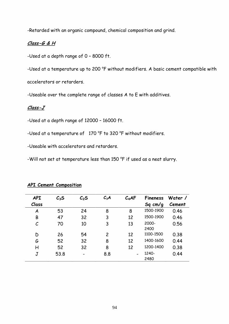
API Cement Composition
API
Class
C3S C2S C3A C4AF Fineness
Sq cm/g
Water /
Cement
A 53 24 8 8 1500-1900 0.46
B 47 32 3 12 1500-1900 0.46
C 70 10 3 13 2000-
2400 0.56
D 26 54 2 12 1100-1500 0.38
G 52 32 8 12 1400-1600 0.44
H 52 32 8 12 1200-1400 0.38
J 53.8 - 8.8 - 1240-
2480 0.44

95
API Cement Properties
Cement Class Mix Water
Gal /s x
Slurdy density
Ppg
Slurry yield
Cuft / sx
Thicken.
Time
113 oF, hr
Comp.
Streng.
110 oF, psi
A 5.2 15.6 1.18 2 ½ 4000
C 6.3 14.8 1.32 1 ¾ 2700
G 5.0 15.8 1.15 1 ¾ 3000
H 4.3 16.5 1.05 2 3700
Effect of Temperature on Compressive Strength
Curing Time 80 oF 100 oF 120 oF 140 oF 160 oF
8 203 1100 2320 2235 2900
12 750 1710 2600 3420 4150
24 1570 2720 3740 4580 5190
Effect of Gel Additions on Class H Slurries
% Gel Mixing Water
gal/sx
Slurry Density
lb/gal
Slurry Volume
cu ft /sx
0 5.18 15.7 1.17
4 7.57 14.2 1.52
8 9.96 13.3 1.86
12 12.4 12.6 2.21
16 14.7 12.2 2.55
Related Documents