Topic #625-000-002 FDOT Design Manual 301-Sequence of Plans Preparation 301 Sequence of Plans Preparation 301.1 General The set of plans depicting in detail all the desired construction work is known as the "Contract Plans Set". This set is assembled as component plans that are associated with a primary work type. See FDM 302.5 for information on contract plans components. The contract plans set should be prepared systematically, undergoing phases of review and revision to ensure technically correct and clear plans. Additional information can be found in FDM 110, 111, 112, and 120. These chapters contain a comprehensive discussion of design processes and activities from initial to final engineering. Prepare Toll Facility Plans in accordance with the Florida’s Turnpike Enterprise current General Tolling Requirements (GTR). The GTR and Addendum(s) to the GTR can be downloaded from the following link: http://www.floridasturnpike.com/design/gtr.html 301.2 Phase Submittals Requirements relating to the design submittals are given in FDM 120. Refer to that chapter for additional guidance in preparing submittals for review by the Department. For bridge submittal requirements see FDM 121. Standard submittal phases are: Phase I, Phase II, Phase III, and Phase IV. RRR, operational improvement, and safety projects typically have two phase reviews, which will be defined in the Scope of Services. Table 301.2.1 summarizes the plans sheet status for each submittal. A phase is considered complete when all review comments have been resolved and documented. An additional sheet titled "Notes for Reviewers" may be placed as the second sheet in the submittal package to call attention to conditions, issues and features unique to the project design. The sheet may be used only for Phase I, Phase II and Phase III submittals. Modification for Non-Conventional Projects: Delete FDM 301.2 and follow FDM 301.3. January 1, 2018 1

Welcome message from author
This document is posted to help you gain knowledge. Please leave a comment to let me know what you think about it! Share it to your friends and learn new things together.
Transcript

Topic #625-000-002 FDOT Design Manual
301-Sequence of Plans Preparation
301 Sequence of Plans Preparation
301.1 General
The set of plans depicting in detail all the desired construction work is known as the "Contract Plans Set". This set is assembled as component plans that are associated with a primary work type. See FDM 302.5 for information on contract plans components. The contract plans set should be prepared systematically, undergoing phases of review and revision to ensure technically correct and clear plans. Additional information can be found in FDM 110, 111, 112, and 120. These chapters contain a comprehensive discussion of design processes and activities from initial to final engineering.
Prepare Toll Facility Plans in accordance with the Florida’s Turnpike Enterprise current General Tolling Requirements (GTR). The GTR and Addendum(s) to the GTR can be downloaded from the following link:
http://www.floridasturnpike.com/design/gtr.html
301.2 Phase Submittals
Requirements relating to the design submittals are given in FDM 120. Refer to that chapter for additional guidance in preparing submittals for review by the Department. For bridge submittal requirements see FDM 121.
Standard submittal phases are: Phase I, Phase II, Phase III, and Phase IV.
RRR, operational improvement, and safety projects typically have two phase reviews, which will be defined in the Scope of Services. Table 301.2.1 summarizes the plans sheet status for each submittal. A phase is considered complete when all review comments have been resolved and documented.
An additional sheet titled "Notes for Reviewers" may be placed as the second sheet in the submittal package to call attention to conditions, issues and features unique to the project design. The sheet may be used only for Phase I, Phase II and Phase III submittals.
Modification for Non-Conventional Projects:
Delete FDM 301.2 and follow FDM 301.3.
January 1, 2018
1

Topic #625-000-002 FDOT Design Manual
301-Sequence of Plans Preparation
Table 301.2.1 Summary of Phase Submittals
Provide the sheets listed as applicable
ITEM PHASE I PHASE II* PHASE III PHASE IV Key Sheet P P C F
Signature Sheet P C F
Summary of Pay Items P C F
Drainage Map P P C F
Interchange Drainage Map P P C F
Typical Section P C C F
Summary of Drainage Structures P C F
Optional Materials Tabulation P C F
Project Layout P C C F
Project Control P C C F
Roadway Plan-Profile P P C F
Traffic Monitoring Site P C F
Special Profile P P C F
Back-of-Sidewalk Profile P C C F
Interchange Layout P P C F
Ramp Terminal Details P C F
Intersection Layout/Detail P P C F
Drainage Structures P C F
Lateral Ditch Plan-Profile P C F
Lateral Ditch Cross Section P C F
Retention/Detention Ponds P C F
Cross Section Pattern P C F
Roadway Soil Survey P C F
Cross Sections P P C F
Stormwater Pollution Prevention Plan P C F
Temporary Traffic Control Plans P P C F
Utility Adjustments P C F
Selective Clearing and Grubbing P C F
Developmental Standard Plans C C F
Mitigation Plans P C F
Miscellaneous Structures Plans P C F
Signing and Pavement Marking Plans P C F
Signalization Plans P C F
Intelligent Transportation System (ITS) Plans P C F
Lighting Plans P C F
Landscape Plans P P C F
Utility Work by Highway Contractor Agreement Plans C F
Summary of Quantities C F Toll Facility Plans
Site/Civil P P C F
Architectural P P C F
Structural P P C F
Electrical P C F
Mechanical P C F
Plumbing P C F
Communications P C F
Systems P C F
Status Key: P - Preliminary C - Complete but subject to change F - Final
* Projects with structures plans component must submit the latest set with the 60% roadway submittal.
January 1, 2018
2

Topic #625-000-002 FDOT Design Manual
301-Sequence of Plans Preparation
301.2.1 Phase I Submittal
Unless otherwise directed by the Department, the following elements are required for a Phase I set of plans:
KEY SHEET
• Location Map with location of project on map
• All applicable Financial Project IDs
• (Federal Funds) notation, if applicable
• Exceptions & Equations
• County Name
• State Road Number
• North arrow
• Approval signature lines
• Railroad crossing (if applicable)
• Revision box
• Governing Standards & Specifications dates
• Department’s Project Manager's Name
• Begin & end project station and begin mile post
• Begin & end bridge stations
• Consultant's name, address, contract number, Certificate of Authorization number and vendor number (if applicable)
DRAINAGE MAP - PLAN VIEW
• North arrow and scale
• Drainage divides and ground elevations
• Drainage areas and flow direction arrows
• Equations
• High water information as required
• Preliminary horizontal alignment
• Section, township, range lines
• Street names
• Begin & end stations of project, construction, bridge, bridge culverts & exceptions
• Existing structures & pipes with relevant information
• State, Federal, county highway numbers (as appropriate)
January 1, 2018
3

Topic #625-000-002 FDOT Design Manual
301-Sequence of Plans Preparation
DRAINAGE MAP - PROFILE VIEW
• Preliminary profile grade & existing ground line
• Horizontal & vertical scale
• Begin & end stations of project, bridges, bridge culverts & exceptions
• Equations
INTERCHANGE DRAINAGE MAP
• North arrow and scale
• Stationing along baselines
• Ramp baselines with nomenclature
• Begin and end bridge stationing
• Preliminary interchange configuration
• R/W lines
• Preliminary interchange drainage with drainage areas and flow direction arrows
TYPICAL SECTIONS
• Mainline and crossroad typical sections
• R/W lines
• Special details (e.g., bifurcated sections, high fills)
• Traffic data
PROJECT LAYOUT
• Plan-profile sheet sequence (mainline and crossroads)
PROJECT CONTROL
• Benchmarks
• Reference points
• Control points
January 1, 2018
4

Topic #625-000-002 FDOT Design Manual
301-Sequence of Plans Preparation
PLAN AND PROFILE - PLAN VIEW
• North arrow and scale
• Baseline of survey, equations
• Curve data (including superelevation)
• Existing topography including utilities
• Preliminary horizontal geometrics/dimensions
• Existing & proposed R/W lines (if available)
• Centerline of construction (if different from the baseline of survey)
• Begin and end stations for the project, bridges, bridge culverts and exceptions
• Reference points (if project layout sheet not included in plans set)
PLAN AND PROFILE - PROFILE VIEW
• Scale
• Appropriate existing utilities
• Bench mark information
• Preliminary profile grade line
• Equations
• Existing ground line with elevations at each end of sheet
• Begin and End Stations for the Project, bridges, bridge culverts and exceptions.
SPECIAL PROFILE
• Scale
• Ramp profile worksheet including nose sections
• Existing ground line of intersections
• Preliminary grade line of intersections
• Preliminary curb return profiles, if applicable
January 1, 2018
5

Topic #625-000-002 FDOT Design Manual
301-Sequence of Plans Preparation
BACK OF SIDEWALK PROFILE (Worksheet)
• Scale
• Begin and end project stations
• Begin and end sidewalk stations
• Cross street locations and elevations
• Drainage flow direction arrows
• Mainline equations
• Existing driveway locations and details
• Superelevation details
• Back of sidewalk profile grades and vertical curve information
• Building floor elevations with offset distance left and right
• Gradeline notation: Specifically the numeric difference relative to roadway profile gradeline
INTERCHANGE DETAIL
• North arrow and scale
• Schematic of traffic flow and volumes
• Proposed bridge limits
• R/W lines
• Preliminary configuration and geometrics
• Quadrant Identification
• Ramp Labels
INTERSECTION LAYOUT
• North arrow and scale
• Existing topography (if applicable)
• Proposed R/W limits
• Length of turn lanes
• Taper lengths
• Existing Utilities
• Geometric dimensions (radii, offsets, widths)
January 1, 2018
6

Topic #625-000-002 FDOT Design Manual
301-Sequence of Plans Preparation
CROSS SECTIONS
(May require accompanying cross section pattern sheet)
• Scale
• Existing ground line
• Existing survey baseline elevations
• Station numbers
• Baseline of survey labeled
• Existing utilities
• Proposed template with profile grade elevations along mainline and cross-streets
TEMPORARY TRAFFIC CONTROL PLANS
• Project specific
• Other worksheets as necessary to convey concept and scope
LANDSCAPE PLANS
• Conceptual landscape plan
301.2.2 Phase II Submittal
Unless otherwise directed by the Department, the following elements are required for a Phase II set of plans:
KEY SHEET
• Index of sheets
• Contract plans and component plans list
SIGNATURE SHEET
• Sections for each Professional of Record
• Index of sheets for each Professional of Record
• Image of the seal(s)
• Appearance of the Digital Signature only to be applied in Phase IV
• (Note: Digital Signatures are not to be applied in this Phase)
January 1, 2018
7

Topic #625-000-002 FDOT Design Manual
301-Sequence of Plans Preparation
SUMMARY OF PAY ITEMS
• Item numbers with descriptions
DRAINAGE MAP - PLAN VIEW
• Proposed structures with structure numbers
• Proposed storm drain pipes
• Flow arrows along proposed ditches
• Retention/Detention ponds, pond number and area size
• Cross drains with pipe sizes and structure numbers
• Bridges/bridge culverts with begin and end stations
• Flood data (if applicable)
DRAINAGE MAP - PROFILE VIEW
• Ditch gradients including DPIs
• Final roadway profile grade line
• Mainline storm drain pipes
• Mainline flow line elevations
• Mainline structures with structure numbers and pipes
• Bridge, Bridge Culvert
• Cross drains with pipe sizes, structure numbers and flow line elevation
OPTIONAL MATERIALS TABULATION
• Material type
• Structure number station and description
• Durability, cover requirements
• Optional culvert material application
• Culvert service life estimator
• Design service life
PROJECT LAYOUT
• Complete
January 1, 2018
8

Topic #625-000-002 FDOT Design Manual
301-Sequence of Plans Preparation
PROJECT CONTROL
• Complete
PLAN AND PROFILE - PLAN VIEW
• Curb return numbers, station ties and elevations
• Proposed drainage structures with structure no.
• Proposed R/W lines
• Existing utilities
• Proposed side drain pipe requirements (including size) for access and intersections
• Final geometrics and dimensions including radii, station pluses, offsets, widths, taper/transition lengths, curve data
• General Notes (if General Notes Sheet not included)
• Flood data if not shown elsewhere
• Limits of wetlands
PLAN AND PROFILE - PROFILE VIEW
• Final profile grades and vertical curve data
• Mainline storm drain pipes
• Proposed special ditches
• Ditch gradients with DPI station and elevation
• Nonstandard superelevation transition details
• High water elevations
• Existing utilities
• Mainline drainage structures with structure numbers
• Cross drains with structure number, size and flow line elevations
TRAFFIC MONITORING SITE
• Project Specific
January 1, 2018
9

Topic #625-000-002 FDOT Design Manual
301-Sequence of Plans Preparation
INTERCHANGE DRAINAGE MAP
• Final geometrics including PC and PT
• Proposed structures with structure numbers
• Proposed storm drain pipes
• Special ditches with DPI and elevation
TYPICAL SECTIONS
• Pavement Design
SPECIAL PROFILE
• Final intersection profile grades
• Final curb return profiles (if applicable)
• Superelevation diagrams as required
• Final ramp profile grades including nose sections
• Preliminary access and frontage road profiles (may contain one or more types of special profiles.)
BACK OF SIDEWALK PROFILE
• Complete
INTERCHANGE LAYOUT
• Curve data including superelevation and design speed
• Coordinate data, stationing and ties
• Access and frontage roads with dimensions and R/W
• Fence location
• Ramp identification
RAMP TERMINAL DETAILS
• Preliminary geometrics
• Radii, transition/taper lengths
• Ramp identification
January 1, 2018
10

Topic #625-000-002 FDOT Design Manual
301-Sequence of Plans Preparation
INTERSECTION LAYOUT
• Limits of proposed construction on side roads
• Applicable notes
• Cross drains with structure numbers and pipe sizes
• Storm drain pipes including sizes
• Final geometrics including dimensions, radii, offsets, station pluses and taper/transition lengths
DRAINAGE STRUCTURES
• Vertical and horizontal scale
• Roadway template with profile grade elevation
• Underground utilities
• Special sections at conflict points
• R/W lines (at critical locations)
• Storm drain construction notes
• Flow arrows
• Applicable notes
• Structure numbers and location station along right side of sheet
• Drainage structures with number, type, size, location and flowline elevations
OUTFALL / LATERAL DITCH SYSTEM - PLAN VIEW
• North arrow and scale
• Roadway centerline
• Existing or survey ditch centerline
• Proposed ditch centerline with stationing
• Begin and end ditch stations
• Equations
• Ditch centerline intersection stations
• R/W lines
• Bearings of ditch and mainline centerlines
• Proposed storm drain pipes
• Ditch PI stations with deflection angle left or right
• Proposed drainage structures with structure numbers
• Existing topography, drainage structures, utilities
• Limits of wetlands
January 1, 2018
11

Topic #625-000-002 FDOT Design Manual
301-Sequence of Plans Preparation
OUTFALL / LATERAL DITCH SYSTEM - PROFILE VIEW
• Bench mark information
• Scale
• Existing ground line
• Proposed ditch profile with grades
• Begin and end ditch stations
• High water elevations
• Proposed storm drain pipes with size
• Existing Utilities
• Overland flow or overtopping elevations
• Proposed drainage structures with structure numbers
• Typical section can be placed in either plan or profile
LATERAL DITCH CROSS SECTIONS
• Horizontal and vertical scale
• Existing ground line
• Station numbers
• Survey centerline and elevation
• R/W
• Begin and end ditch stations
• Begin and end excavation stations
• Earthwork quantities
• Existing utilities
• Total earthwork quantity in cubic yards
• Proposed template with ditch bottom elevation
RETENTION/DETENTION POND DETAILS
• North arrow and scale
• Roadway centerline ties
• Proposed pond centerline with stationing
• Begin and end pond stations
• Side slopes, dimensions, and elevations
• R/W lines
• Berm, fence and gate locations
• Soil boring information
• Proposed pond drainage structures with structure numbers
• Existing topography, drainage structures, utilities
• Pond sections (2 perpendicular to each other)
• Pond Typical Section
• Limits of wetlands
January 1, 2018
12

Topic #625-000-002 FDOT Design Manual
301-Sequence of Plans Preparation
RETENTION/DETENTION POND CROSS SECTIONS
• Horizontal and vertical scale
• Existing ground line
• Station numbers
• Begin and end pond stationing
• Pond centerline and elevations
• R/W
• Soil borings
• Water table
• Extent of unsuitable material
• Earthwork quantities
• Existing utilities
• Proposed template with bottom elevation
CROSS SECTION PATTERN
• North arrow and scale
• Interchange layout
• Access and frontage roads
• Mainline and ramp stationing
• Begin and end bridge stations
• Cross section location lines
• Ramp baselines with nomenclature and stationing
ROADWAY SOIL SURVEY
• Soil data
• Project specific
CROSS SECTIONS
• R/W
• Special ditch bottom elevations
• Equivalent stations for ramps and mainline
• Mainline equation stations
• Soil borings
• Water table
• Extent of unsuitable material
• Proposed template with profile grade elevation
• Earthwork Columns
• Begin and end stationing for project, construction and earthwork, bridge and bridge culvert
• Existing utilities affected by the template and where unsuitable materials are present
January 1, 2018
13

Topic #625-000-002 FDOT Design Manual
301-Sequence of Plans Preparation
STORMWATER POLLUTION PREVENTION PLANS (SWPPP)
• Narrative Description (with supplemental topographic maps, when used)
TEMPORARY TRAFFIC CONTROL PLANS
• Preliminary traffic control plan
• Detour plan
• Phasing plan
• R/W - existing and additional if required
• Existing Utilities
UTILITY ADJUSTMENTS
• All existing utilities highlighted
SELECTIVE CLEARING AND GRUBBING
• Limits of construction by station and type of selective clearing and grubbing
MITIGATION PLANS
• Project Specific
MISCELLANEOUS STRUCTURES PLANS
• Retaining walls (Cast in place, proprietary, temporary) if required
SIGNING AND PAVEMENT MARKING PLANS - KEY SHEET
• Financial Project ID
• (Federal Funds) notation, if applicable
• State Road Number
• County Name
• FDOT Project Manager's Name
• Begin/end stations & exceptions
• Station Equations (if location map is shown)
• Engineer of Record
• Consultants name & address, if applicable
SIGNING AND PAVEMENT MARKING PLANS - TABULATION OF QUANTITIES
• Project Specific
January 1, 2018
14

Topic #625-000-002 FDOT Design Manual
301-Sequence of Plans Preparation
SIGNING AND PAVEMENT MARKING PLANS - PLAN SHEETS
• North arrow and scale
• Basic Roadway Geometrics
• Begin/End Stations and Exceptions
• Station equations
• Conflicting utilities, lighting or drainage
• Pavement markings
• Sign locations
• Applicable pay items
SIGNING AND PAVEMENT MARKING PLANS - SIGN DETAIL SHEETS, GUIDE SIGN WORK SHEETS
• Project Specific
SIGNALIZATION PLANS - KEY SHEET
• Financial Project ID
• (Federal Funds) notation, if applicable
• State Road Number
• County Name
• FDOT Project Manager's Name
• Begin/end stations & exceptions
• Station Equations (if location map is shown)
• Engineer of Record
• Consultants name & address, if applicable
SIGNALIZATION PLANS - TABULATION OF QUANTITIES
• Project Specific
SIGNALIZATION PLANS - PLAN SHEET
• North arrow and scale
• Basic Roadway Geometrics
• Begin/End Stations and Exceptions
• Station Equations
• Conflicting utilities, lighting or drainage
• Signal Pole Location
• Type and location of loops
• Type and location of signal heads
• Pedestrian Signal
• Location of Stop Bars
• Location of Pedestrian Crosswalks
• Sheet Title
• Applicable pay items
January 1, 2018
15

Topic #625-000-002 FDOT Design Manual
301-Sequence of Plans Preparation
SIGNALIZATION PLANS - POLE SCHEDULE
• Pole location, number, type
• Pole dimensions
• Pay item number and quantity
• Joint use pole details, if applicable
• Foundation design
SIGNALIZATION PLANS - INTERCONNECT/ COMMUNICATION CABLE PLAN
• Placement of interconnect/communication cable
• Conflicting utilities, lighting or drainage
• Other project specific details
ITS PLANS - KEY SHEET
• Financial Project ID
• (Federal Funds) notation, if applicable
• State Road Number
• County Name
• FDOT Project Manager's Name
• Begin/end stations & exceptions
• Station Equations (if location map is shown)
• Engineer of Record
• Consultants name & address, if applicable
ITS PLANS - TABULATION OF QUANTITIES
• Project Specific
ITS PLANS - PLAN SHEETS
• Project Specific, but must include:
o North arrow and scale
o Basic Roadway Geometrics
o Begin/End Stations and Exceptions
o Station equations
o Conflicting utilities, lighting or drainage
o Applicable pay items
January 1, 2018
16

Topic #625-000-002 FDOT Design Manual
301-Sequence of Plans Preparation
ITS PLANS - DETAIL SHEETS
• Project Specific
LIGHTING PLANS - KEY SHEET
• Financial Project ID
• (Federal Funds) notation, if applicable
• State Road Number
• County Name
• FDOT Project Manager's Name
• Begin/end stations & exceptions
• Station Equations (if location map is shown)
• Engineer of Record
• Consultants name & address, if applicable
LIGHTING PLANS - TABULATION OF QUANTITIES
• Project Specific
LIGHTING PLANS - POLE DATA AND LEGEND SHEET
• Each pole by number with location, arm length, mounting height and luminaire wattage noted.
• Design value for light intensities and uniformity ratios shown.
• Legend and sheet title
LIGHTING PLANS - PLAN SHEETS
• North arrow and scale
• Basic Roadway Geometrics
• Begin/End Stations and Equations
• Station Equations
• Conflicting utilities, drainage, signal poles, etc.
• Sheet title
• Applicable pay items
• Pole symbols shown at correct station location and approximate offset
January 1, 2018
17

Topic #625-000-002 FDOT Design Manual
301-Sequence of Plans Preparation
LIGHTING PLANS - HIGH MAST
• Foundation detail sheets (project specific)
• Boring data sheets (project specific)
• Conflicting utilities, drainage, lighting
LANDSCAPE PLANS - KEY SHEET
• Financial Project ID
• (Federal Funds) notation, if applicable
• Fiscal year and sheet number
• State Road Number
• County Name
• FDOT Project Manager's Name
• Begin/end stations & exceptions
• Station Equations (if location map is shown)
• Landscape Architect of Record name and registration number
• Consultants name, address, and contract number, if applicable
• Index of landscape plans
LANDSCAPE PLANS - TABULATION OF QUANTITIES AND PLANT SCHEDULE
• Project Specific
LANDSCAPE PLANS - TABULATION OF QUANTITIES AND SCHEDULE FOR IRRIGATION AND SITE AMENITIES
• Project Specific
January 1, 2018
18
Topic #625-000-002 FDOT Design Manual
301-Sequence of Plans Preparation
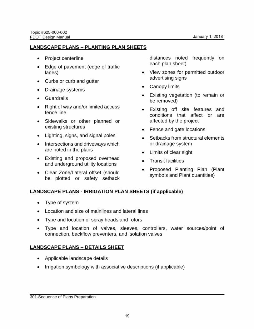
LANDSCAPE PLANS – PLANTING PLAN SHEETS
• Project centerline
• Edge of pavement (edge of traffic lanes)
• Curbs or curb and gutter
• Drainage systems
• Guardrails
• Right of way and/or limited access fence line
• Sidewalks or other planned or existing structures
• Lighting, signs, and signal poles
• Intersections and driveways which are noted in the plans
• Existing and proposed overhead and underground utility locations
• Clear Zone/Lateral offset (should be plotted or safety setback
distances noted frequently on each plan sheet)
• View zones for permitted outdoor advertising signs
• Canopy limits
• Existing vegetation (to remain or be removed)
• Existing off site features and conditions that affect or are affected by the project
• Fence and gate locations
• Setbacks from structural elements or drainage system
• Limits of clear sight
• Transit facilities
• Proposed Planting Plan (Plant symbols and Plant quantities)
LANDSCAPE PLANS - IRRIGATION PLAN SHEETS (if applicable)
• Type of system
• Location and size of mainlines and lateral lines
• Type and location of spray heads and rotors
• Type and location of valves, sleeves, controllers, water sources/point of connection, backflow preventers, and isolation valves
LANDSCAPE PLANS – DETAILS SHEET
• Applicable landscape details
• Irrigation symbology with associative descriptions (if applicable)
January 1, 2018
19

Topic #625-000-002 FDOT Design Manual
301-Sequence of Plans Preparation
301.2.3 Phase III Submittal
Typically, the remaining work to be done is to:
(1) Address Phase II comments,
(2) Complete the Summary of Quantities (SQ) sheets,
(3) Update the Financial Management (FM) system (see FDM 111.2.1), and
(4) Provide final drainage tabulations.
Estimate the Work Zone Traffic Control items paid for on a 'per day' basis and include them in the Phase III submittal. The Department’s construction office will perform a biddability review and will establish construction duration as a part of the Phase III review after receiving the plan set. This information should be included in the Phase III review comments transmitted back to the EOR.
Utility Work by Highway Contractor (UWHC) Agreement Plans, consisting of a key sheet, and mainline plan-profile showing proposed utility horizontal and vertical locations, are also to be included in the Phase III submittal.
Review comments must be provided to the EOR for incorporation of the comments into the plans. When the review comments have been resolved and documented by the designer, the plans are ready to proceed to completion.
301.2.4 Phase IV Submittal
Plans are final (Phase IV Plans) when:
(1) Corrections noted during the Phase III submittal review are complete,
(2) Work Zone Traffic Control pay items have been revised based on the established construction duration and the Summary of Quantities (SQ) sheets are finalized,
(3) The assigned Construction Contract number is placed on the Key Sheet(s), and
(4) The Engineer of Record’s construction cost estimate is complete.
301.2.5 PS&E Submittal
There are a minimum of two Plans, Specifications, and Estimates (PS&E) submittals:
(1) All specification, plans processing, or estimates comments are made.
January 1, 2018
20

Topic #625-000-002 FDOT Design Manual
301-Sequence of Plans Preparation
(2) Verify all comments from the first PS&E submittal have been addressed. Additional submittals may be required until accepted.
After all corrections noted during the 100% submittal review are complete, the plans are considered final and production ready. The plans may be shelved or proceed to PS&E Submittal in accordance with the process described in FDM 131. Coordinate with the District Plans Processing office for required submittal(s) following Phase IV submittal.
301.3 Design-Build Phase Submittals
FDM 301.3 applies exclusively to Design-Build projects. Requirements relating to the design process for various submittals are given in FDM 120. Refer to that chapter for additional guidance in preparing submittals for review by the Department. For bridge submittal requirements see FDM 220. For Design-Build projects, the standard submittal phases are:
(1) Technical Proposal
(2) 90% Component Plans
(3) Final Component Plans
Table 301.3.1 summarizes the plans sheet status required for each submittal.
An additional sheet titled "Notes for Reviewers" may be placed as the second sheet in the submittal package to call attention to conditions, issues and features unique to the project design. The sheet is to be used only in the review process and is not included in the final plans.
January 1, 2018
21

Topic #625-000-002 FDOT Design Manual
301-Sequence of Plans Preparation
Table 301.3.1 Summary of Design-Build Phase Submittals
Provide the sheets listed as applicable
ITEM TECHNICAL
PROPOSAL 90% PLANS FINAL PLANS
Key Sheet P F
Signature Sheet P F
Drainage Map P C F
Interchange Drainage Map P C F
Typical Section P C F
Summary of Drainage Structures C F
Project Layout C F
Project Control P C F
Roadway Plan-Profile P C F
Traffic Monitoring Site P C F
Special Profile C F
Back-of-Sidewalk Profile C Interchange Layout P C F
Intersection Layout/Detail P C F
Drainage Structures C F
Lateral Ditch Plan-Profile C F
Lateral Ditch Cross Section C F
Retention/Detention Pond Details C F
Roadway Soil Survey C F
Cross Sections C F
Temporary Traffic Control Plans P C F
Utility Adjustments C Selective Clearing and Grubbing C Developmental Standard Plans C F
Mitigation Plans C F
Miscellaneous Structures Plans C F
Signing and Pavement Marking Plans P C F
Signalization Plans C F
Intelligent Transportation System (ITS) Plans C F
Lighting Plans C F
Landscape Plans C F
Utility Work by Highway Contractor Agreement Plans C F
Toll Facility Plans Site/Civil P P F
Architectural P P F
Structural P P F
Electrical P F
Mechanical P F
Plumbing P F
Communications P F
Systems P F
Status Key: P – Preliminary C - Complete but subject to change F – Final
January 1, 2018
22

Topic #625-000-002 FDOT Design Manual
301-Sequence of Plans Preparation
301.3.1 Technical Proposal Submittal Requirements
Submit a complete set of 11” X 17” plan sheets for the Technical Proposal Submittal. As a supplement to the plan set, select plan sheets, no larger than 24” X 36” or roll plot(s) no larger than 24” X 96”, may be submitted. Supplemental plan sheets or roll plots are desirable for such roadway features that cannot be presented adequately on 11” X 17” sheets; e.g., complex interchanges, Maintenance of Traffic phases, large complex intersections. Unless otherwise directed by the Department, the following elements are required for a Technical Proposal Submittal:
DRAINAGE MAP - PLAN VIEW
• Drainage divides and flow direction arrows
• High water information as required
• Preliminary horizontal alignment with stationing
• State, Federal, County highway numbers (as appropriate)
• Proposed storm drain trunk line and outfall locations
• Proposed Retention/Detention Pond Location
INTERCHANGE DRAINAGE MAP - PLAN VIEW
• Preliminary interchange drainage with drainage areas and flow direction arrows
TYPICAL SECTIONS
• Mainline and crossroad typical sections
• R/W lines
• Traffic data
• Pavement Design
PROJECT CONTROL
• Benchmarks
• Reference Points
• Control Points
January 1, 2018
23

Topic #625-000-002 FDOT Design Manual
301-Sequence of Plans Preparation
PLAN AND PROFILE - PLAN VIEW
• North arrow and scale
• Baseline of survey, equations
• Curve data (including superelevation)
• Existing topography including utilities
• Preliminary horizontal geometrics/dimensions
• Existing & proposed R/W lines (if available)
• Centerline of construction (if different from the baseline of survey)
• Begin and end stations for the project and stations of equations and exceptions
• Existing utilities
• Guide sign locations
• Limits of wetlands
PLAN AND PROFILE - PROFILE VIEW
• North arrow and scale
• Appropriate existing utilities
• Preliminary profile grade line
• Existing ground line with elevations at each end of sheet
• Begin and end stations for the project and stations of equations and exceptions
• Final profile grades and vertical curve data
• High water elevations
TRAFFIC MONITORING SITE
• Project Specific
INTERCHANGE LAYOUT
• Curve data including superelevation and design speed
• Stationing and ties
• Access or frontage roads with dimensions and R/W
• Ramp identification
January 1, 2018
24

Topic #625-000-002 FDOT Design Manual
301-Sequence of Plans Preparation
INTERSECTION LAYOUT
• North arrow and scale
• Existing topography (if applicable)
• Proposed R/W limits
• Length of turn lanes
• Geometric dimensions (radii, offsets, widths)
• Limits of proposed construction along side roads
TEMPORARY TRAFFIC CONTROL PLANS
• Project specific
• Other worksheets as necessary to convey concept and scope
• Preliminary traffic control plan
• Detour plan
• Phasing plan
• R/W – existing and additional if required
SIGNING AND PAVEMENT MARKING PLANS ‑ SIGN DETAIL SHEETS
• Preliminary layout of multi-column and overhead guide sign worksheets
TOLL FACILITY PLANS
• Site/Civil
• Architectural
• Structural
January 1, 2018
25

Topic #625-000-002 FDOT Design Manual
301-Sequence of Plans Preparation
301.3.2 90% Plans Component Submittal Requirements
Unless otherwise directed by the Department, the following elements are required for a 90% Plans Component Submittal:
KEY SHEET
• Location Map with location of project on map
• All applicable Financial Project IDs
• (Federal Funds) notation, if applicable
• Exceptions & Equations
• County Name
• State Road Number
• North arrow and scale
• Approval signature lines
• Railroad crossing (if applicable)
• Revision box
• Governing Standards & Specifications dates
• Department’s Project Manager's Name
• Begin & end project station and begin mile post
• Begin & end bridge stations
• Consultant's name, address, contract number, Certificate of Authorization number and vendor number (if applicable)
• Index of sheets
• Contract plans and component plans list
SIGNATURE SHEET
• Sections for each Professional of Record
• Index of sheets for each Professional of Record
• Image of the seal(s)
• (Note: Digital Signatures are not to be applied in this Phase)
January 1, 2018
26

Topic #625-000-002 FDOT Design Manual
301-Sequence of Plans Preparation
DRAINAGE MAP - PLAN VIEW
• North arrow and scale
• Drainage divides and ground elevations
• Drainage areas and flow direction arrows
• Equations
• High water information as required
• Preliminary horizontal alignment
• Section, township, range lines
• Street names
• Begin & end stations of project, bridge, bridge culverts & exceptions
• Existing structures & pipes with relevant information
• Proposed structures with structure numbers
• Proposed storm drain pipes
• Flow arrows along proposed ditches
• Retention/Detention ponds, pond number and area size
• Cross drains with pipe sizes and structure numbers
• Bridges/bridge culverts with begin and end stations
• Flood data (if applicable)
• State, Federal, county highway numbers (as appropriate)
DRAINAGE MAP - PROFILE VIEW
• Horizontal & vertical scale
• Begin & end stations of project, bridges, bridge culverts & exceptions
• Equations
• Ditch gradients including DPIs
• Final roadway profile grade line
• Mainline storm drain pipes
• Mainline flow line elevations
• Mainline structures with structure numbers and pipes
• Bridge, Bridge Culvert
• Cross drains with pipe sizes, structure numbers and flow line elevation
January 1, 2018
27

Topic #625-000-002 FDOT Design Manual
301-Sequence of Plans Preparation
INTERCHANGE DRAINAGE MAP
• North arrow and scale
• Stationing along baselines
• Ramp baselines with nomenclature
• Begin and end bridge stationing
• Final interchange configuration
• R/W lines
• Final Interchange drainage with drainage areas and flow direction arrows
• Final geometrics including PC and PT
• Proposed structures with structure numbers
• Proposed storm drain pipes
• Special ditches with DPI and elevation
TYPICAL SECTIONS
• Mainline and crossroad typical sections
• R/W lines
• Special details (e.g., bifurcated sections, high fills)
• Traffic data
• Pavement Design
SUMMARY OF DRAINAGE STRUCTURES
• Complete
PROJECT LAYOUT
• Plan-profile sheet sequence (mainline and crossroads)
PROJECT CONTROL
• Complete
January 1, 2018
28

Topic #625-000-002 FDOT Design Manual
301-Sequence of Plans Preparation
ROADWAY PLAN PROFILE - PLAN VIEW
• North arrow and scale
• Baseline of survey, equations
• Curve data (including superelevation)
• Existing topography including utilities
• Preliminary horizontal geometrics/dimensions
• Existing & proposed R/W lines (if available)
• Centerline of construction (if different from the baseline of survey)
• Begin and end stations for the project, bridges, bridge culverts and exceptions
• Reference points (if project survey control sheet not included in plans set)
• Curb return numbers, station ties and elevations
• Proposed drainage structures with structure nos.
• Proposed R/W lines
• Existing utilities
• Limits of wetlands
• Flood data if not shown elsewhere
• Proposed side drain pipe requirements (including size) for access and intersections
• Final geometrics and dimensions including radii, station pluses, offsets, widths, taper/transition lengths, curve data
• General notes (if project layout sheet not included)
ROADWAY PLAN PROFILE - PROFILE VIEW
• Begin and end stations for the project and stations of equations and exceptions
• Existing ground line with elevations at each end of sheet
• Final profile grades and vertical curve data
• High water elevations
• Appropriate existing utilities
• Mainline storm drain pipes
• Proposed special ditches
• Ditch gradients with DPI station and elevation
• Non-standard superelevation transition details
• High water elevations
• Mainline drainage structures with structure numbers
• Cross drains with structure number, size and flow line elevations
January 1, 2018
29

Topic #625-000-002 FDOT Design Manual
301-Sequence of Plans Preparation
TRAFFIC MONITORING SITE
• Project Specific
SPECIAL PROFILE
• Scale
• Existing ground line of intersections
• Final intersection profile grades
• Final curb return profiles (if applicable)
• Superelevation diagrams as required
• Final ramp profile grades including nose sections
• Final access and frontage road profiles (may contain one or more types of special profiles.)
BACK-OF-SIDEWALK PROFILE
• Scale
• Begin and end project stations
• Begin and end sidewalk stations
• Cross-street locations and elevations
• Drainage flow direction arrows
• Mainline equations
• Existing driveway locations and details
• Superelevation details
• Back-of-sidewalk profile grades and vertical curve information
• Building floor elevations with offset distance left and right
• Grade line notation: Specifically the numeric difference relative to roadway profile grade line
INTERCHANGE LAYOUT
• North arrow and scale
• Quadrant Identification
• Ramp Labels
• Schematic of traffic flow and volumes
• Proposed bridge limits
• R/W lines
• Final configuration and geometrics
• Curve data including superelevation and design speed
• Coordinate data, stationing and ties
• Access and frontage roads with dimensions and R/W
• Fence location
January 1, 2018
30

Topic #625-000-002 FDOT Design Manual
301-Sequence of Plans Preparation
RAMP TERMINAL DETAILS
• Ramp identification
• Final geometrics
• Radii, transition/taper lengths
INTERSECTION LAYOUT
• North arrow and scale
• Existing topography (if applicable)
• Proposed R/W limits
• Length of turn lanes
• Taper lengths
• Existing Utilities
• Geometric dimensions (radii, offsets, widths)
• Limits of proposed construction on side roads
• Applicable notes
• Cross drains with structure numbers and pipe sizes
• Storm drain pipes including sizes
• Final geometrics including dimensions, radii, offsets, station pluses and taper/transition lengths
DRAINAGE STRUCTURES
• Vertical and horizontal scale
• Roadway template with profile grade elevation
• Underground utilities
• Special sections at conflict points
• R/W lines (at critical locations)
• Storm drain construction notes
• Flow arrows
• Applicable notes
• Structure numbers and location station along right side of sheet
• Drainage structures with numbers in numerical order, type, size, location and flow line elevations
January 1, 2018
31

Topic #625-000-002 FDOT Design Manual
301-Sequence of Plans Preparation
OUTFALL / LATERAL DITCH SYSTEM - PLAN VIEW
• North arrow and scale
• Roadway centerline
• Existing and survey ditch centerline
• Proposed ditch centerline with stationing
• Begin and end ditch stations
• Equations
• Ditch centerline intersection stations
• R/W lines
• Bearings of ditch and mainline centerlines
• Proposed storm drain pipes
• Ditch PI stations with deflection angle left or right
• Proposed drainage structures with structure numbers
• Existing topography, drainage structures, utilities
• Limits of wetlands
OUTFALL / LATERAL DITCH SYSTEM - PROFILE VIEW
• Bench mark information
• Scale
• Existing ground line
• Proposed ditch profile with grades
• Begin and end ditch stations
• High water elevations
• Proposed storm drain pipes with size
• Existing Utilities
• Overland flow or overtopping elevations
• Proposed drainage structures with structure numbers
• Typical section can be placed in either plan or profile
LATERAL DITCH CROSS SECTIONS
• Horizontal and vertical scale
• Existing ground line
• Station numbers
• Survey centerline and elevation
• R/W
• Begin and end ditch stations
• Begin and end excavation stations
• Existing utilities
• Proposed template with ditch bottom elevation
January 1, 2018
32

Topic #625-000-002 FDOT Design Manual
301-Sequence of Plans Preparation
RETENTION/DETENTION POND DETAILS
• North arrow and scale
• Roadway centerline ties
• Proposed pond centerline with stationing
• Begin and end pond stations
• Side slopes, dimensions, and elevations
• R/W lines
• Berm, fence and gate locations
• Soil boring information
• Proposed pond drainage structures with structure numbers
• Existing topography, drainage structures, utilities
• Pond sections (2 perpendicular to each other)
• Pond Typical Section
• Limits of wetlands
RETENTION/DETENTION POND CROSS SECTIONS
• Horizontal and vertical scale
• Existing ground line
• Station numbers
• Begin and end pond stationing
• Pond centerline and elevations
• R/W
• Soil borings
• Water table
• Extent of unsuitable material
• Earthwork quantities
• Existing utilities
• Proposed template with bottom elevation
ROADWAY SOIL SURVEY
• Soil data • Project specific
CROSS SECTIONS
• Scale
• Existing ground line
• Existing survey baseline elevations
• Station numbers
• Baseline of survey labeled
• Existing utilities
• Proposed template with profile grade elevations along mainline and cross-streets as necessary
January 1, 2018
33

Topic #625-000-002 FDOT Design Manual
301-Sequence of Plans Preparation
TEMPORARY TRAFFIC CONTROL PLANS
• Project specific
• Other worksheets as necessary to convey concept and scope.
• Final traffic control plan
• Detour plan
• Phasing plan
• R/W - existing and additional if required
• Existing Utilities
UTILITY ADJUSTMENTS
• All existing utilities highlighted
SELECTIVE CLEARING AND GRUBBING
• Limits of construction by station and type of selective clearing and grubbing
MITIGATION PLANS
• Project Specific
MISCELLANEOUS STRUCTURES PLANS
• Retaining walls (Cast in place, proprietary, temporary) if required
SIGNING AND PAVEMENT MARKING PLANS - KEY SHEET
• Financial Project ID
• (Federal Funds) notation, if applicable
• State Road Number
• County Name
• Department’s Project Manager's Name
• Begin/end stations & exceptions
• Station Equations (if location map is shown)
• Engineer of Record
• Consultants name & address, if applicable
January 1, 2018
34

Topic #625-000-002 FDOT Design Manual
301-Sequence of Plans Preparation
SIGNING AND PAVEMENT MARKING PLANS - PLAN SHEETS
• North arrow and scale
• Basic Roadway Geometrics
• Begin/End Stations and Exceptions
• Station equations
• Conflicting utilities, lighting or drainage
• Pavement markings
• Sign locations
GUIDE SIGN WORK SHEETS
• Project Specific
SIGNALIZATION PLANS - KEY SHEET
• Financial Project ID
• (Federal Funds) notation, if applicable
• State Road Number
• County Name
• Department’s Project Manager's Name
• Begin/end stations & exceptions
• Station Equations (if location map is shown)
• Engineer of Record
• Consultants name & address, if applicable
SIGNALIZATION PLANS - PLAN SHEET
• North arrow and scale
• Basic Roadway Geometrics
• Begin/End Stations and Exceptions
• Station Equations
• Conflicting utilities, lighting or drainage
• Signal Pole Location
• Type and location of loops
• Type and location of signal heads
• Pedestrian Signal
• Location of Stop Bars
• Location of Pedestrian Crosswalks
• Sheet Title
January 1, 2018
35

Topic #625-000-002 FDOT Design Manual
301-Sequence of Plans Preparation
SIGNALIZATION PLANS - POLE SCHEDULE
• Pole location, number, type
• Pole dimensions
• Joint use pole details, if applicable
• Foundation design
SIGNALIZATION PLANS - INTERCONNECT/ COMMUNICATION CABLE PLAN
• Placement of interconnect/communication cable
• Conflicting utilities, lighting or drainage
• Other project specific details
ITS PLANS - KEY SHEET
• Financial Project ID
• (Federal Funds) notation, if applicable
• State Road Number
• County Name
• Department’s Project Manager's Name
• Begin/end stations & exceptions
• Station Equations (if location map is shown)
• Engineer of Record
• Consultants name & address, if applicable
ITS PLANS - PLAN SHEETS
• Project Specific, but must include:
• North arrow and scale
• Basic Roadway Geometrics
• Begin/End Stations and Exceptions
• Station equations
• Conflicting utilities, lighting or drainage
ITS PLANS - DETAIL SHEETS
• Project Specific
January 1, 2018
36

Topic #625-000-002 FDOT Design Manual
301-Sequence of Plans Preparation
LIGHTING PLANS - KEY SHEET
• Financial Project ID
• (Federal Funds) notation, if applicable
• State Road Number
• County Name
• Department’s Project Manager's Name
• Begin/end stations & exceptions
• Station Equations (if location map is shown)
• Engineer of Record
• Consultants name & address, if applicable
LIGHTING PLANS - POLE DATA AND LEGEND SHEET
• Each pole by number with location, arm length, mounting height and luminaire wattage
• Design value for light intensities and uniformity ratios shown
• Legend and sheet title
LIGHTING PLANS - PLAN SHEETS
• North arrow and scale
• Basic Roadway Geometrics
• Begin/End Stations and Equations
• Station Equations
• Conflicting utilities, drainage, signal poles
• Sheet title
• Pole symbols shown at correct station location and approximate offset
LIGHTING PLANS - HIGH MAST
• Foundation detail sheets (project specific)
• Boring data sheets (project specific)
• Conflicting utilities, drainage, lighting
January 1, 2018
37

Topic #625-000-002 FDOT Design Manual
301-Sequence of Plans Preparation
LANDSCAPE PLANS – KEY SHEET
• Financial Project ID
• (Federal Funds) notation, if applicable
• Fiscal year and sheet number
• State Road Number
• County Name
• Department’s Project Manager's Name
• Begin/end stations & exceptions
• Station Equations (if location map is shown)
• Landscape Architect of Record name and registration number
• Consultants name, address, and contract number, if applicable
• Index of landscape plans
LANDSCAPE PLANS – PLANTING PLAN SHEETS
• Project centerline
• Edge of pavement (edge of traffic lanes)
• Curbs or curb and gutter
• Drainage systems
• Guardrails
• R/W or limited access fence line
• Sidewalks or other planned or existing structures
• Lighting, signs, and signal poles
• Intersections and driveways which are noted in the plans
• Existing and proposed overhead and underground utility locations
• Clear Zone/Lateral offset (should be plotted or safety setback distances noted frequently on each plan sheet)
• View zones for permitted outdoor advertising signs
• Canopy limits
• Existing vegetation (to remain or be removed)
• Existing off site features and conditions that affect or are affected by the project
• Fence and gate locations
• Setbacks from structural elements or drainage system
• Limits of clear sight
• Transit facilities
• Proposed Planting Plan
•
January 1, 2018
38

Topic #625-000-002 FDOT Design Manual
301-Sequence of Plans Preparation
LANDSCAPE PLANS - IRRIGATION PLAN SHEETS
(if applicable)
• Type of system
• Location and size of mainlines and lateral lines
• Type and location of spray heads and rotors
• Type and location of valves, sleeves, controllers, water sources/point of connection, backflow preventers, and isolation valves
LANDSCAPE PLANS – DETAILS SHEET
• Applicable landscape details
• Irrigation symbology with associative descriptions (if applicable)
301.3.3 Final Plans Submittal
Ordinarily, the remaining work to be done will be to:
(1) Comply with comments received as a result of the 90% review,
(2) Update all plan sheets and the Financial Management (FM) system,
(3) Provide final drainage tabulations for review, and
(4) Provide Utility Work by Highway Contractor (UWHC) Agreement Plans, consisting of a key sheet, and mainline plan-profile showing proposed utility horizontal and vertical locations.
The Department will provide a "marked up" set of the plans and review comments to the EOR for incorporation into the plan set. When the review comments have been resolved and documented by the designer, the plans are ready to proceed to completion.
301.3.4 Released For Construction Plans
After corrections noted in the Final Plans submittal have been satisfactorily resolved as determined by the Department, the Department’s Project Manager will initial, date and stamp each submittal as “Released for Construction”. Only signed and sealed plans stamped “Released for Construction” by the Department’s Project Manager are valid. Work performed by the Design-Build Firm prior to the Department’s release of Plans will be at the Design-Build Firm’s risk.
January 1, 2018
39

Topic #625-000-001 FDOT Design Manual
301-Sequence of Plans Preparation
301.4 Roundabout Review Submittal
Roundabout designs require the approval by the State Roadway Design Engineer. Provide a Roundabout Submittal Package to Central Office Roadway Design for review as early in the design process as practical.
The Roundabout Submittal Package includes the following:
(1) Plan sheets (PDF and CADD)
(a) Key Sheet with location map
(b) Roundabout typical sections
(c) Roundabout layout, including;
i. Dimensions for all major geometric components including splitter islands, circulatory roadway, truck apron, central island, bypass lanes, landscape buffers, sidewalks/multi-use paths, cross walks, bicycle bail-out ramps
ii. Existing and proposed R/W lines
iii. Significant topographic features including buildings, driveways, drainage structures, utilities, bicycle, pedestrian, and transit facilities.
(2) Traffic Forecast for Design Year (PDF), including;
(a) AM and PM peak hourly through and turning volumes
(b) AM and PM peak pedestrian crossing movements
(c) Peak hour factor
(d) Percentage of heavy vehicles
(e) Volume distribution across lanes for multi-lane entries
(3) Operational Analysis input and output (PDF)
(4) Fastest Path Speed Checks in accordance with NCHRP 672 Section 6.7.1 (PDF and CADD)
(5) Swept Path of the Design Vehicle in accordance with NCHRP 672 Section 6.7.2 (PDF and CADD)
(6) Sight Distance Checks in accordance with NCHRP 672 Section 6.7.3 (PDF and CADD)
Central Office Roadway Design will provide review comments and schedule a meeting with the project team to resolve any issues. When the agreed to changes to the design have been verified, an approval memorandum will be issued by the State Roadway Design Engineer.
January 1, 2018
40
Related Documents