3. Technical Description

Welcome message from author
This document is posted to help you gain knowledge. Please leave a comment to let me know what you think about it! Share it to your friends and learn new things together.
Transcript

3. Technical Description
38 ENGINE — 3VZ–FE ENGINE
ENGINE
3VZ–FE ENGINE
� DESCRIPTION
The 3VZ–FE engine is a V–6, 3.0–liter, 24–valve DOHC engine based on the reputable 2VZ–FE engine in the ES250.The total piston displacement is increased and other changes incorporated to deliver greater power output while enhancingquietness.
Since the 3VZ–FE and the 2VZ–FE engines are basically the same, only major differences are explained below.
39ENGINE — 3VZ–FE ENGINE
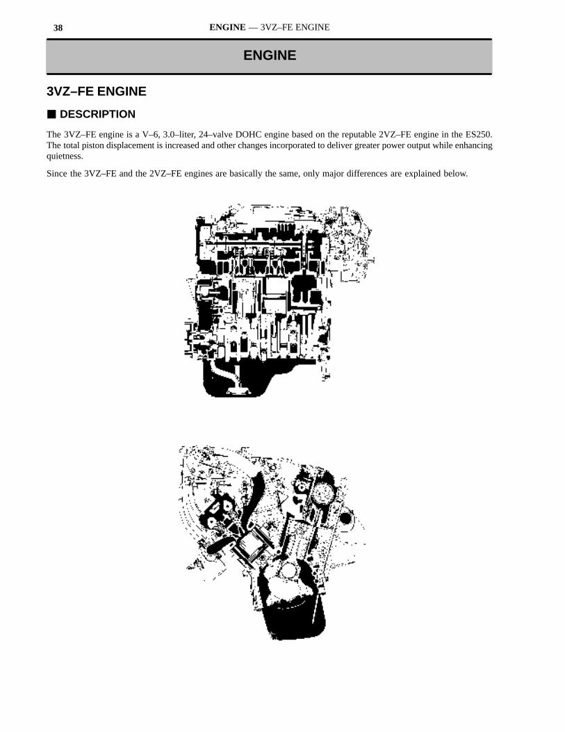
� ENGINE SPECIFICATIONS AND PERFORMANCE CURVE
Engine3VZ FE 2VZ FE
g
Item3VZ–FE 2VZ–FE
No. of Cyls. & Arrangement 6–Cylinder, V Type ←
Valve Mechanism 4–Valve DOHC,Belt & Gear Drive
←
Combustion Chamber Pentroof Type ←
Manifold Cross–Flow ←
Displacement cm3 (cu. in.) 2959 (180.6) 2508 (153.0)
Bore x Stroke mm (in.) 87.5 x 82.0 (3.44 x 3.23) 87.5 x 69.5 (3.44 x 2.74)
Compression Ratio 9.6 : 1 9.0 : 1
Max. Output [SAE–NET] 138 kW @ 5200 rpm(185 HP @ 5200 rpm)
116 kW @ 5600 rpm
(156 HP @ 5600 rpm)
Max. Torque [SAE–NET] 264 N.m @ 4400 rpm(195 ft.lbf @ 4400 rpm)
217 N.m @ 4400(160 ft.lbf @ 4400)
IntakeOpen 8� BTDC ←
Valve Timing
IntakeClose 42� ABDC 38� ABDC
Valve Timing
ExhaustOpen 46� BBDC 38� BBDC
ExhaustClose 4� ATDC ←
Fuel Octane Number RON 96 ←
Oil Grade API SG, EC–II API SG
40 ENGINE — 3VZ–FE ENGINE
� MAJOR DIFFERENCES
Major differences between the 3VZ–FE and previous 2VZ–FE engines are listed below.
Components Details
Engine Proper
� Both the total piston displacement and the compression ratio are increased toincrease the power output.
� Upright, small–diameter type intake ports are used in the cylinder head to in-crease the intake efficiency.
� The crankshaft has 9 semi–balance counterweights.
Cooling System � An electronically controlled hydraulic cooling fan system is used to improvecooling performance and reduce cooling fan noise.
Intake and Exhaust System
� The shape of the intake air chamber and intake manifold is modified to in-crease the intake efficiency.
� ACIS (Acoustic Control Induction System) is used to deliver high power out-put in all engine speed ranges.
Fuel System � An air–assisted fuel system is used to promote atomizing of the fuel for im-proved fuel economy.
Engine Control System
� A sequential multi point fuel injection system improves the engine response.
� An oxygen sensor is installed for each bank to independently implement air–fuel ratio feedback control for the left and right bank.
� A knock sensor is installed for each bank to improve knocking detection.
� A test mode function is added to the diagnostic system.
� ENGINE PROPER
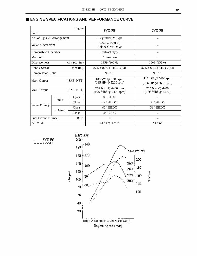
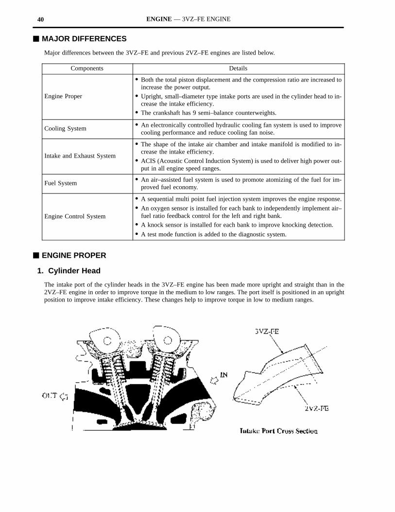
1. Cylinder Head
The intake port of the cylinder heads in the 3VZ–FE engine has been made more upright and straight than in the2VZ–FE engine in order to improve torque in the medium to low ranges. The port itself is positioned in an uprightposition to improve intake efficiency. These changes help to improve torque in low to medium ranges.
41ENGINE — 3VZ–FE ENGINE
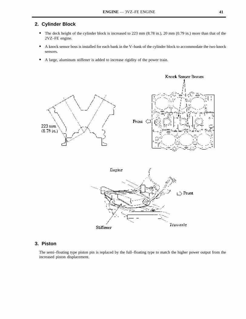
2. Cylinder Block
� The deck height of the cylinder block is increased to 223 mm (8.78 in.), 20 mm (0.79 in.) more than that of the2VZ–FE engine.
� A knock sensor boss is installed for each bank in the V–bank of the cylinder block to accommodate the two knocksensors.
� A large, aluminum stiffener is added to increase rigidity of the power train.
3. Piston
The semi–floating type piston pin is replaced by the full–floating type to match the higher power output from theincreased piston displacement.
42 ENGINE — 3VZ–FE ENGINE
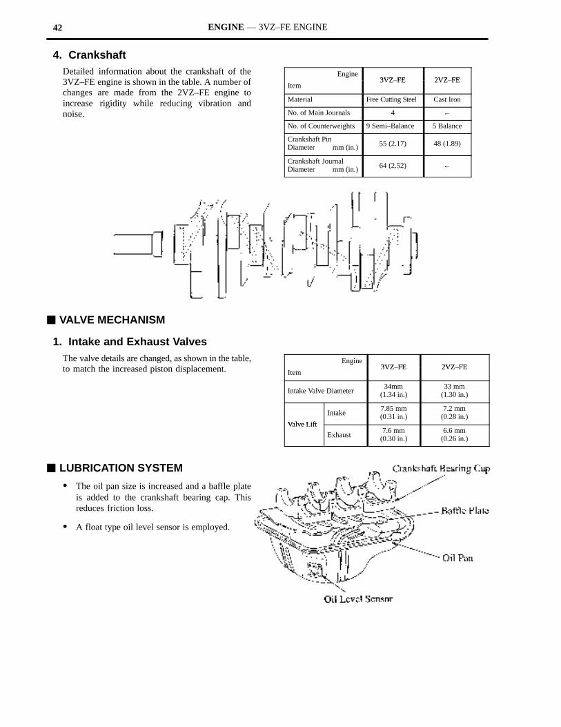
4. CrankshaftDetailed information about the crankshaft of the3VZ–FE engine is shown in the table. A number ofchanges are made from the 2VZ–FE engine toincrease rigidity while reducing vibration andnoise.
Engine3VZ FE 2VZ FE
g
Item3VZ–FE 2VZ–FE
Material Free Cutting Steel Cast Iron
No. of Main Journals 4 ←
No. of Counterweights 9 Semi–Balance 5 Balance
Crankshaft PinDiameter mm (in.) 55 (2.17) 48 (1.89)
Crankshaft JournalDiameter mm (in.) 64 (2.52) ←
� VALVE MECHANISM
1. Intake and Exhaust ValvesThe valve details are changed, as shown in the table,to match the increased piston displacement.
Engine3VZ FE 2VZ FE
g
Item3VZ–FE 2VZ–FE
Intake Valve Diameter34mm
(1.34 in.)33 mm
(1.30 in.)
Valve Lift
Intake7.85 mm(0.31 in.)
7.2 mm(0.28 in.)
Valve Lift
Exhaust7.6 mm
(0.30 in.)6.6 mm
(0.26 in.)
� LUBRICATION SYSTEM
� The oil pan size is increased and a baffle plateis added to the crankshaft bearing cap. Thisreduces friction loss.
� A float type oil level sensor is employed.
43ENGINE — 3VZ–FE ENGINE
� COOLING SYSTEM
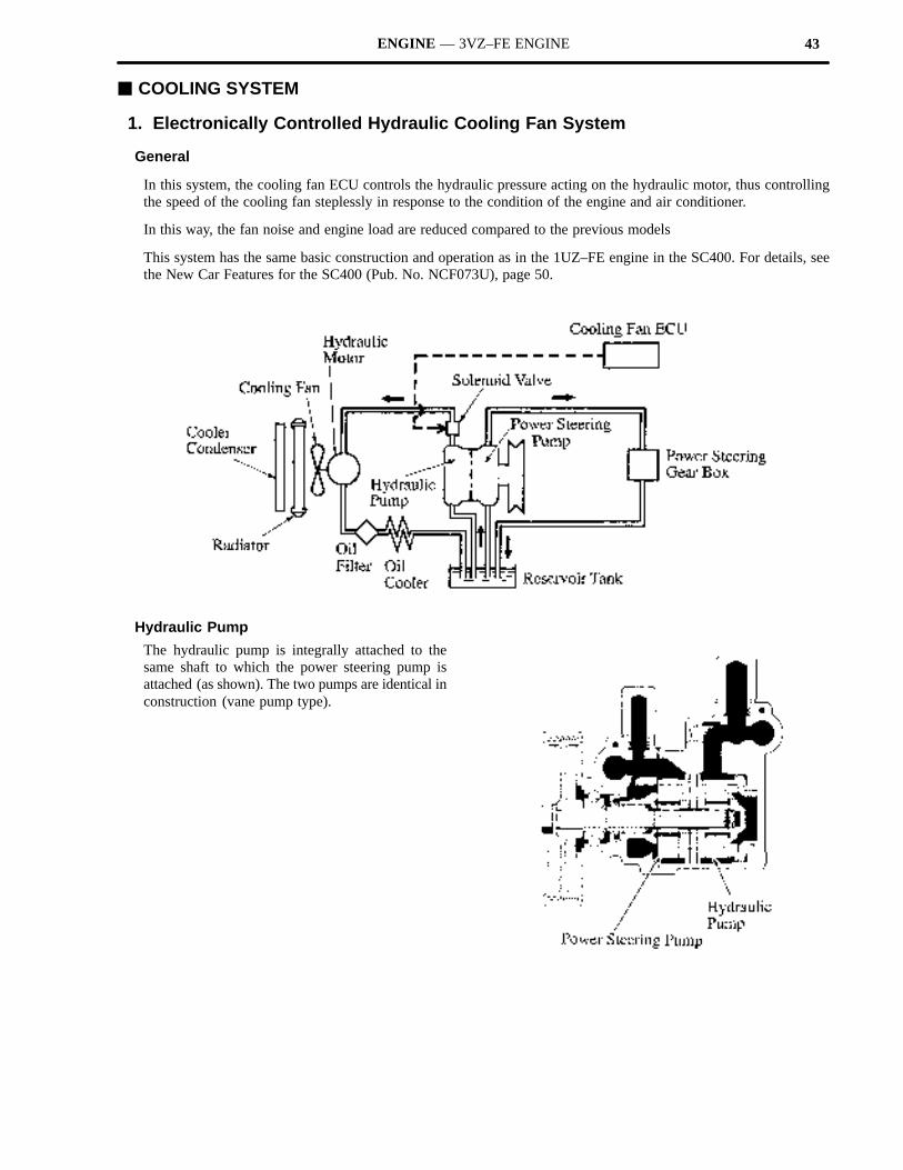
1. Electronically Controlled Hydraulic Cooling Fan System
General
In this system, the cooling fan ECU controls the hydraulic pressure acting on the hydraulic motor, thus controllingthe speed of the cooling fan steplessly in response to the condition of the engine and air conditioner.
In this way, the fan noise and engine load are reduced compared to the previous models
This system has the same basic construction and operation as in the 1UZ–FE engine in the SC400. For details, seethe New Car Features for the SC400 (Pub. No. NCF073U), page 50.
Hydraulic Pump
The hydraulic pump is integrally attached to thesame shaft to which the power steering pump isattached (as shown). The two pumps are identical inconstruction (vane pump type).
44 ENGINE — 3VZ–FE ENGINE
� INTAKE AND EXHAUST SYSTEM
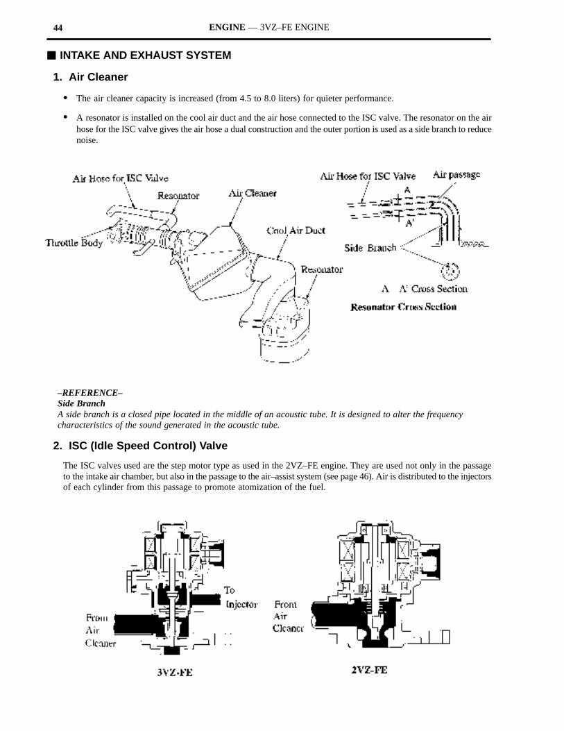
1. Air Cleaner
� The air cleaner capacity is increased (from 4.5 to 8.0 liters) for quieter performance.
� A resonator is installed on the cool air duct and the air hose connected to the ISC valve. The resonator on the airhose for the ISC valve gives the air hose a dual construction and the outer portion is used as a side branch to reducenoise.
–REFERENCE–Side BranchA side branch is a closed pipe located in the middle of an acoustic tube. It is designed to alter the frequencycharacteristics of the sound generated in the acoustic tube.
2. ISC (Idle Speed Control) Valve
The ISC valves used are the step motor type as used in the 2VZ–FE engine. They are used not only in the passageto the intake air chamber, but also in the passage to the air–assist system (see page 46). Air is distributed to the injectorsof each cylinder from this passage to promote atomization of the fuel.
45ENGINE — 3VZ–FE ENGINE
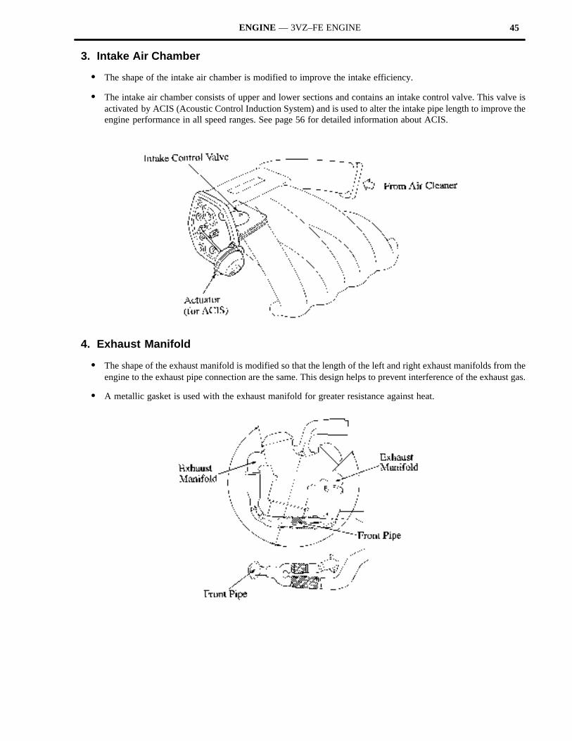
3. Intake Air Chamber
� The shape of the intake air chamber is modified to improve the intake efficiency.
� The intake air chamber consists of upper and lower sections and contains an intake control valve. This valve isactivated by ACIS (Acoustic Control Induction System) and is used to alter the intake pipe length to improve theengine performance in all speed ranges. See page 56 for detailed information about ACIS.
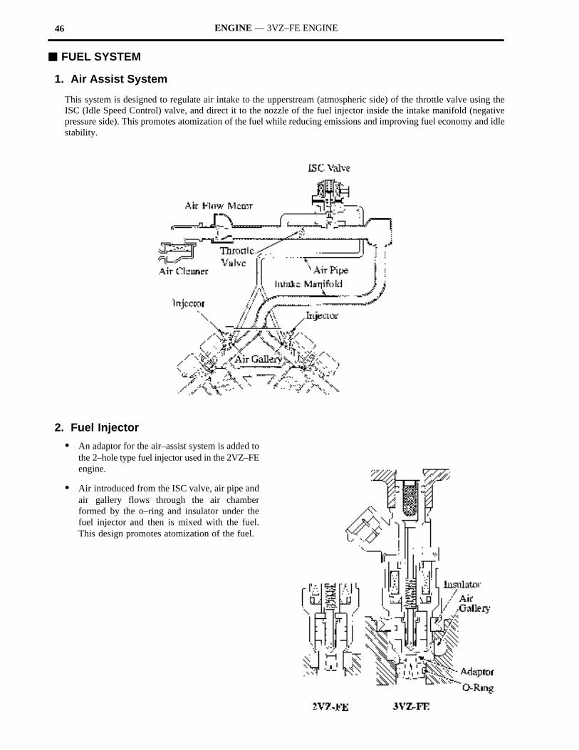
4. Exhaust Manifold
� The shape of the exhaust manifold is modified so that the length of the left and right exhaust manifolds from theengine to the exhaust pipe connection are the same. This design helps to prevent interference of the exhaust gas.
� A metallic gasket is used with the exhaust manifold for greater resistance against heat.
46 ENGINE — 3VZ–FE ENGINE
� FUEL SYSTEM
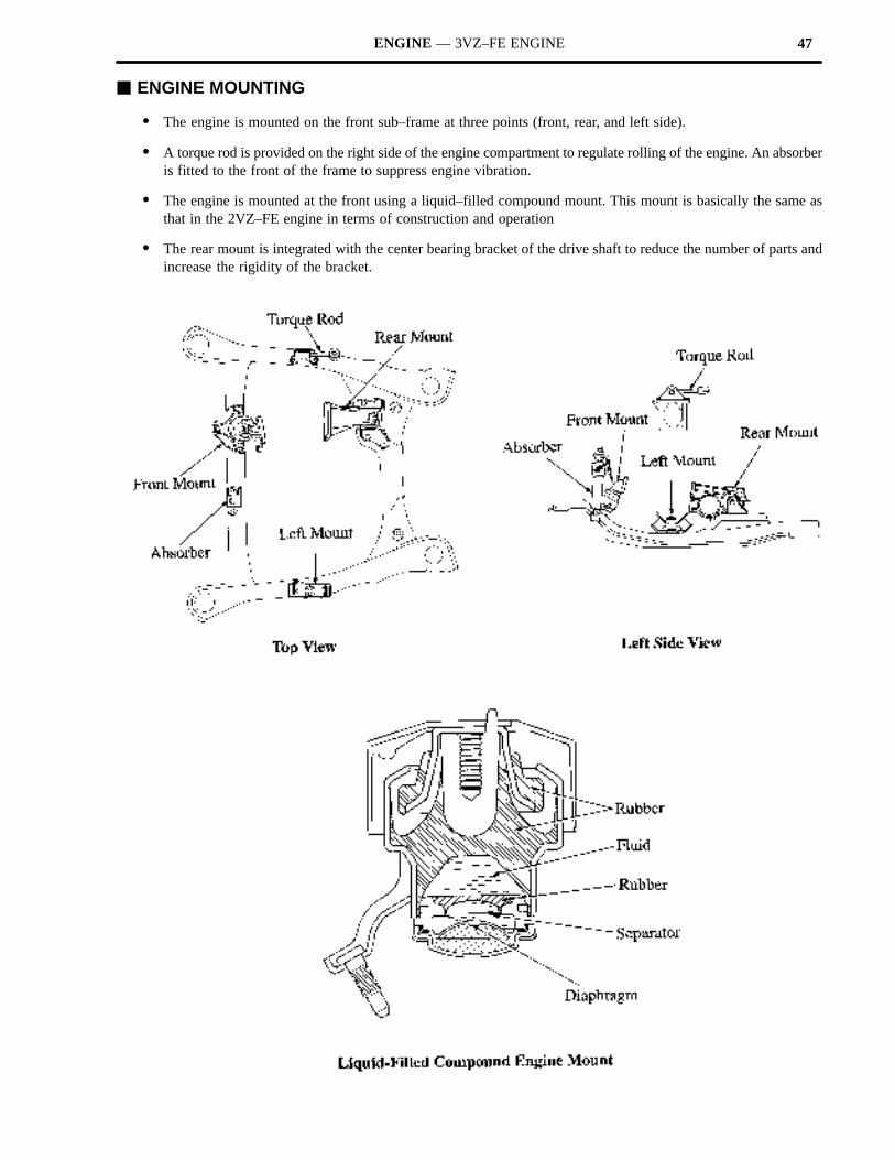
1. Air Assist System
This system is designed to regulate air intake to the upperstream (atmospheric side) of the throttle valve using theISC (Idle Speed Control) valve, and direct it to the nozzle of the fuel injector inside the intake manifold (negativepressure side). This promotes atomization of the fuel while reducing emissions and improving fuel economy and idlestability.
2. Fuel Injector
� An adaptor for the air–assist system is added tothe 2–hole type fuel injector used in the 2VZ–FEengine.
� Air introduced from the ISC valve, air pipe andair gallery flows through the air chamberformed by the o–ring and insulator under thefuel injector and then is mixed with the fuel.This design promotes atomization of the fuel.
47ENGINE — 3VZ–FE ENGINE
� ENGINE MOUNTING
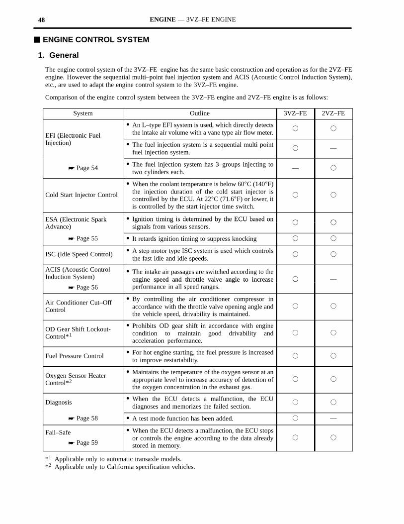
� The engine is mounted on the front sub–frame at three points (front, rear, and left side).
� A torque rod is provided on the right side of the engine compartment to regulate rolling of the engine. An absorberis fitted to the front of the frame to suppress engine vibration.
� The engine is mounted at the front using a liquid–filled compound mount. This mount is basically the same asthat in the 2VZ–FE engine in terms of construction and operation
� The rear mount is integrated with the center bearing bracket of the drive shaft to reduce the number of parts andincrease the rigidity of the bracket.
48 ENGINE — 3VZ–FE ENGINE
� ENGINE CONTROL SYSTEM
1. General
The engine control system of the 3VZ–FE engine has the same basic construction and operation as for the 2VZ–FEengine. However the sequential multi–point fuel injection system and ACIS (Acoustic Control Induction System),etc., are used to adapt the engine control system to the 3VZ–FE engine.
Comparison of the engine control system between the 3VZ–FE engine and 2VZ–FE engine is as follows:
System Outline 3VZ–FE 2VZ–FE
EFI (Electronic Fuel
� An L–type EFI system is used, which directly detectsthe intake air volume with a vane type air flow meter.
� �
EFI (Electronic Fuel Injection) � The fuel injection system is a sequential multi point
fuel injection system.� —
� Page 54 � The fuel injection system has 3–groups injecting totwo cylinders each.
— �
Cold Start Injector Control
� When the coolant temperature is below 60°C (140°F)the injection duration of the cold start injector iscontrolled by the ECU. At 22°C (71.6°F) or lower, itis controlled by the start injector time switch.
� �
ESA (Electronic Spark � Ignition timing is determined by the ECU based on� �
ESA (Electronic Spark Advance)
Ignition timing is determined by the ECU based onsignals from various sensors.
� �
� Page 55 � It retards ignition timing to suppress knocking � �
ISC (Idle Speed Control) � A step motor type ISC system is used which controlsthe fast idle and idle speeds.
� �
ACIS (Acoustic Control Induction System)
� The intake air passages are switched according to theengine speed and throttle valve angle to increase � —
� Page 56engine speed and throttle valve angle to increaseperformance in all speed ranges.
�
Air Conditioner Cut–OffControl
� By controlling the air conditioner compressor inaccordance with the throttle valve opening angle andthe vehicle speed, drivability is maintained.
� �
OD Gear Shift Lockout-Control*1
� Prohibits OD gear shift in accordance with enginecondition to maintain good drivability andacceleration performance.
� �
Fuel Pressure Control � For hot engine starting, the fuel pressure is increasedto improve restartability.
� �
Oxygen Sensor HeaterControl*2
� Maintains the temperature of the oxygen sensor at anappropriate level to increase accuracy of detection ofthe oxygen concentration in the exhaust gas.
� �
Diagnosis � When the ECU detects a malfunction, the ECUdiagnoses and memorizes the failed section.
� �
� Page 58 � A test mode function has been added. � —
Fail–Safe
� Page 59
� When the ECU detects a malfunction, the ECU stopsor controls the engine according to the data alreadystored in memory.
� �
*1 Applicable only to automatic transaxle models.*2 Applicable only to California specification vehicles.
49ENGINE — 3VZ–FE ENGINE
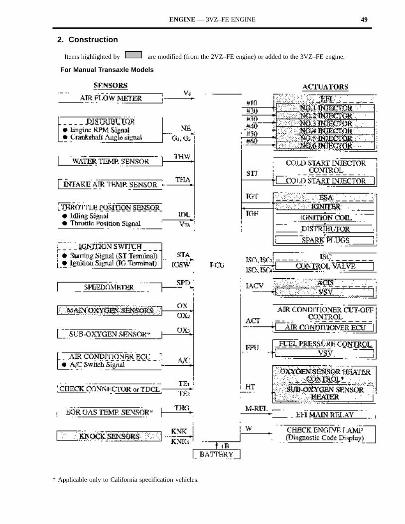
2. Construction
Items highlighted by are modified (from the 2VZ–FE engine) or added to the 3VZ–FE engine.
For Manual Transaxle Models
* Applicable only to California specification vehicles.
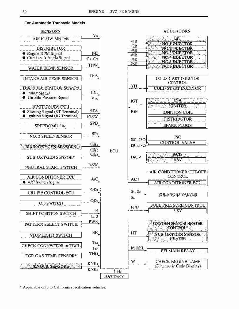
50 ENGINE — 3VZ–FE ENGINE
For Automatic Transaxle Models
* Applicable only to California specification vehicles.
51ENGINE — 3VZ–FE ENGINE
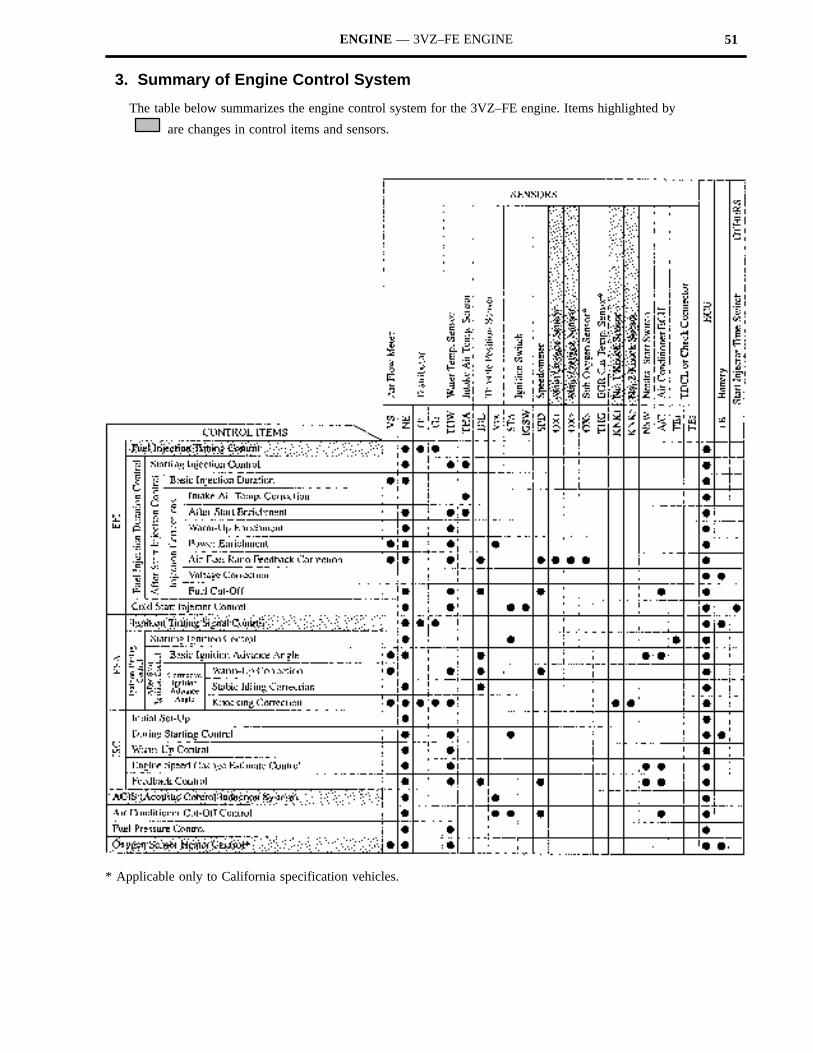
3. Summary of Engine Control System
The table below summarizes the engine control system for the 3VZ–FE engine. Items highlighted by
are changes in control items and sensors.
* Applicable only to California specification vehicles.
52 ENGINE — 3VZ–FE ENGINE
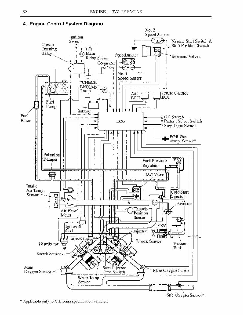
4. Engine Control System Diagram
* Applicable only to California specification vehicles.
53ENGINE — 3VZ–FE ENGINE
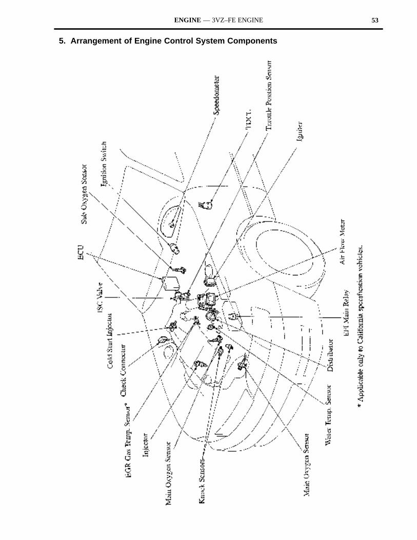
5. Arrangement of Engine Control System Components
54 ENGINE — 3VZ–FE ENGINE
6. Modification of Main Components
The main components construction and operation of the 3VZ–FE engine remain basically the same as the 2VZ–FEengine. However, the specification changes shown below have been made.
Engine3VZ FE 2VZ FE
Component3VZ–FE 2VZ–FE
Oxygen SensorMain without Heater, 1 (for Left Bank)
without Heater, 1 (for Right Bank)with Heater, 1
Oxygen SensorSub* with Heater, 1 without Heater, 1
Knock SensorBuilt–In Piezoelectric
Element Type, 2(for Left and Right Banks)
Built–In PiezoelectricElement Type, 1
(between Left and Right Banks)
* Applicable only to California specification vehicles.
7. EFI (Electronic Fuel Injection)
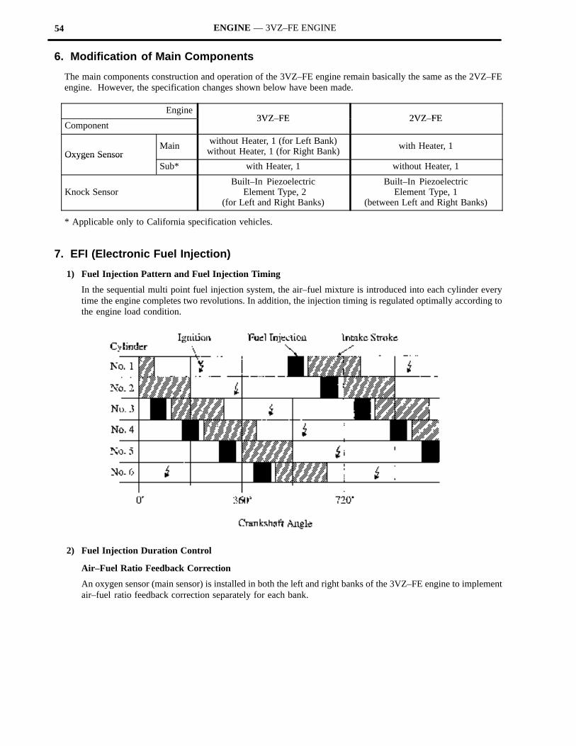
1) Fuel Injection Pattern and Fuel Injection Timing
In the sequential multi point fuel injection system, the air–fuel mixture is introduced into each cylinder everytime the engine completes two revolutions. In addition, the injection timing is regulated optimally according tothe engine load condition.
2) Fuel Injection Duration Control
Air–Fuel Ratio Feedback Correction
An oxygen sensor (main sensor) is installed in both the left and right banks of the 3VZ–FE engine to implementair–fuel ratio feedback correction separately for each bank.
55ENGINE — 3VZ–FE ENGINE
8. ESA (Electronic Spark Advance)
General
Part of the operation–sharing between the ECU and the igniter in the ESA system has been modified.
A: Determination of ignition timingB: Output of ignition timing signal (IGT)C: Calculation of primary current
(ignition coil) energizing start timingD: Interruption of primary current
Requirements for IgnitionEngine
3VZ FE 2VZ FEg
Part3VZ–FE 2VZ–FE
ECU A, B and C A and B
Igniter (C)* and D C and D
*Correction of C
Principle of Operation
1) Determination of Ignition Timing
As in the 2VZ–FE engine, the ECU calculates the basic ignition advance angle based on the engine speed andintake air volume. Additionally, it is adjusted according to the coolant temperature and other factors to determinethe ignition timing.
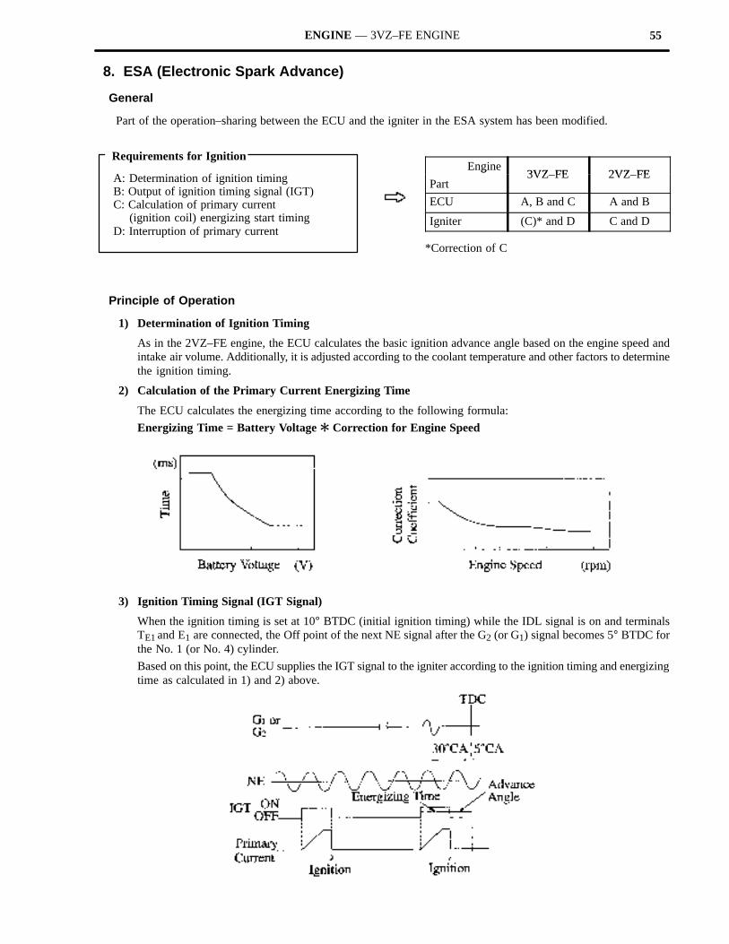
2) Calculation of the Primary Current Energizing Time
The ECU calculates the energizing time according to the following formula:
Energizing Time = Battery Voltage � Correction for Engine Speed
3) Ignition Timing Signal (IGT Signal)
When the ignition timing is set at 10° BTDC (initial ignition timing) while the IDL signal is on and terminalsTE1 and E1 are connected, the Off point of the next NE signal after the G2 (or G1) signal becomes 5° BTDC forthe No. 1 (or No. 4) cylinder.
Based on this point, the ECU supplies the IGT signal to the igniter according to the ignition timing and energizingtime as calculated in 1) and 2) above.
56 ENGINE — 3VZ–FE ENGINE
9. ACIS (Acoustic Control Induction System
General
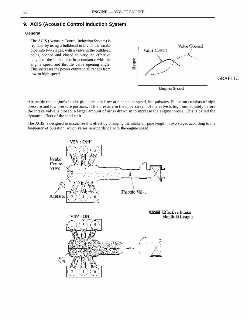
The ACIS (Acoustic Control Induction System) isrealized by using a bulkhead to divide the intakepipe into two stages, with a valve in the bulkheadbeing opened and closed to vary the effectivelength of the intake pipe in accordance with theengine speed and throttle valve opening angle.This increases the power output in all ranges fromlow to high speed.
GRAPHIC
Air inside the engine’s intake pipe does not flow at a constant speed, but pulsates. Pulsation consists of highpressure and low pressure portions. If the pressure in the upperstream of the valve is high immediately beforethe intake valve is closed, a larger amount of air is drawn in to increase the engine torque. This is called thedynamic effect of the intake air.
The ACIS is designed to maximize this effect by changing the intake air pipe length in two stages according to thefrequency of pulsation, which varies in accordance with the engine speed.
57ENGINE — 3VZ–FE ENGINE
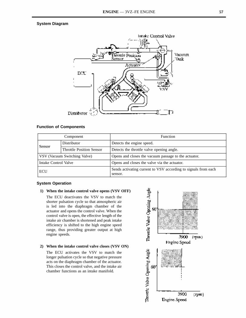
System Diagram
Function of Components
Component Function
SensorDistributor Detects the engine speed.
SensorThrottle Position Sensor Detects the throttle valve opening angle.
VSV (Vacuum Switching Valve) Opens and closes the vacuum passage to the actuator.
Intake Control Valve Opens and closes the valve via the actuator.
ECU Sends activating current to VSV according to signals from each sensor.
System Operation
1) When the intake control valve opens (VSV OFF)
The ECU deactivates the VSV to match theshorter pulsation cycle so that atmospheric airis led into the diaphragm chamber of theactuator and opens the control valve. When thecontrol valve is open, the effective length of theintake air chamber is shortened and peak intakeefficiency is shifted to the high engine speedrange, thus providing greater output at highengine speeds.
2) When the intake control valve closes (VSV ON)
The ECU activates the VSV to match thelonger pulsation cycle so that negative pressureacts on the diaphragm chamber of the actuator.This closes the control valve, and the intake airchamber functions as an intake manifold.
58 ENGINE — 3VZ–FE ENGINE
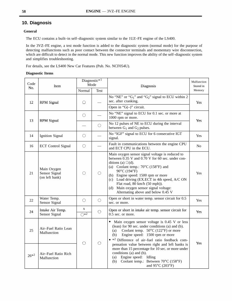
10. Diagnosis
General
The ECU contains a built–in self–diagnostic system similar to the 1UZ–FE engine of the LS400.
In the 3VZ–FE engine, a test mode function is added to the diagnostic system (normal mode) for the purpose ofdetecting malfunctions such as poor contact between the connector terminals and momentary wire disconnection,which are difficult to detect in the normal mode. This new function improves the ability of the self–diagnostic systemand simplifies troubleshooting.
For details, see the LS400 New Car Features (Pub. No. NCF054U).
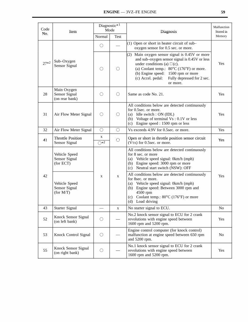
Diagnostic Items
CodeNo Item
Diagnostic*1
Mode DiagnosisMalfunction
Stored inNo. Item
Normal TestDiagnosis Stored in
Memory
12 RPM Signal � —
No “NE” or “G1” and “G2” signal to ECU within 2sec. after cranking. Yes12 RPM Signal �
Open in “G(–)” circuit.Yes
13 RPM Signal� — No “NE” signal to ECU for 0.1 sec. or more at
1000 rpm or more.Yes13 RPM Signal
— �No 12 pulses of NE to ECU during the intervalbetween G1 and G2 pulses.
Yes
14 Ignition Signal � — No “IGF” signal to ECU for 6 consecutive IGTsignal.
Yes
16 ECT Control Signal � — Fault in communications between the engine CPUand ECT CPU in the ECU.
No
21Main OxygenSensor Signal(on left bank)
� �
Main oxygen sensor signal voltage is reduced tobetween 0.35 V and 0.70 V for 60 sec. under con-ditions (a) ∼ (d).(a) Coolant temp.: 70°C (158°F) and
90°C (194°F)(b) Engine speed: 1500 rpm or more(c) Load driving (EX.ECT in 4th speed, A/C ON
Flat road, 80 km/h (50 mph)).(d) Main oxygen sensor signal voltage:
Alternating above and below 0.45 V
Yes
22 Water Temp.Sensor Signal
� �Open or short in water temp. sensor circuit for 0.5sec. or more.
Yes
24 Intake Air Temp. x�
Open or short in intake air temp. sensor circuit for Yes24 Intake Air Temp. Sensor Signal �*2
�Open or short in intake air temp. sensor circuit for0.5 sec. or more.
Yes
25 Air–Fuel Ratio LeanMalfunction
� �
� Main oxygen sensor voltage is 0.45 V or less(lean) for 90 sec. under conditions (a) and (b).(a) Coolant temp. 50°C (122°F) or more(b) Engine speed: 1500 rpm or more
� *2 Difference of air–fuel ratio feedback com-i l b i h d l f b k i Yes
26*2 Air–Fuel Ratio RichMalfunction
� � pensation value between right and left banks ismore than 15 percentage for 10 sec. or more underconditions (a) and (b).(a) Engine speed: Idling(b) Coolant temp.: Between 70°C (158°F)
and 95°C (203°F)
Yes
59ENGINE — 3VZ–FE ENGINE
CodeNo Item
Diagnostic*1 Mode Diagnosis
MalfunctionStored in
No. ItemNormal Test
Diagnosis Stored inMemory
� —(1) Open or short in heater circuit of sub–
oxygen sensor for 0.5 sec. or more.
27*2Sub–Oxygen Sensor Signal
� �
(2) Main oxygen sensor signal is 0.45V or moreand sub–oxygen sensor signal is 0.45V or lessunder conditions (a) ∼ (c).(a) Coolant temp.: 80°C (176°F) or more.(b) Engine speed: 1500 rpm or more(c) Accel. pedal: Fully depressed for 2 sec.
or more.
Yes
28Main Oxygen Sensor Signal (on rear bank)
� � Same as code No. 21. Yes
31 Air Flow Meter Signal � �
All conditions below are detected continuouslyfor 0.5sec. or more.(a) Idle switch : ON (IDL)(b) Voltage of terminal Vs : 0.1V or less(c) Engine speed : 1500 rpm or less
Yes
32 Air Flow Meter Signal � � Vs exceeds 4.9V for 0.5sec. or more. Yes
41 Throttle Position x�
Open or short in throttle position sensor circuit Yes41 Throttle Position Sensor Signal �*2
�Open or short in throttle position sensor circuit(VTA) for 0.5sec. or more.
Yes
Vehicle SpeedSensor Signal(for ECT)
All conditions below are detected continuouslyfor 8 sec. or more(a) Vehicle speed signal: 0km/h (mph)(b) Engine speed: 3000 rpm or more(c) Neutral start switch (NSW): OFF
42
Vehicle SpeedSensor Signal(for M/T)
x x All conditions below are detected continuouslyfor 8sec. or more.(a) Vehicle speed signal: 0km/h (mph)(b) Engine speed: Between 3000 rpm and
4500 rpm(c) Coolant temp.: 80°C (176°F) or more(d) Load driving
Yes
43 Starter Signal — x No starter signal to ECU. No
52 Knock Sensor Signal(on left bank)
� —No.2 knock sensor signal to ECU for 2 crankrevolutions with engine speed between 1600 rpm and 5200 rpm.
Yes
53 Knock Control Signal � —Engine control computer (for knock control)malfunction at engine speed between 650 rpmand 5200 rpm.
No
55 Knock Sensor Signal(on right bank)
� —No.1 knock sensor signal to ECU for 2 crankrevolutions with engine speed between 1600 rpm and 5200 rpm.
Yes
60 ENGINE — 3VZ–FE ENGINE
Code Item
Diagnostic*1
ModeDiagnosis
MalfunctionStored in
CodeNo.
ItemNormalMode
TestMode
Diagnosis Stored inMemory
71*2 EGR System Malfunction
� �
EGR gas temp. is 70°C (158°F) or below for 1∼4min. under conditions (a) and (b).(a) Coolant temp.: 60°C (140°F) or more(b) EGR operation possible (EX.ECT in D
range, A/C ON, 96km/h (60mph), Flat road).
Yes
51SwitchCondition Signal
— x
(1) 3 sec. or more after engine starts, idle switch OFF (IDL).
(2) Neutral start switch OFF (NSW).(Shift position in “R”, “D”, “2”, or “L” ranges)
(3) A/C switch ON.
No
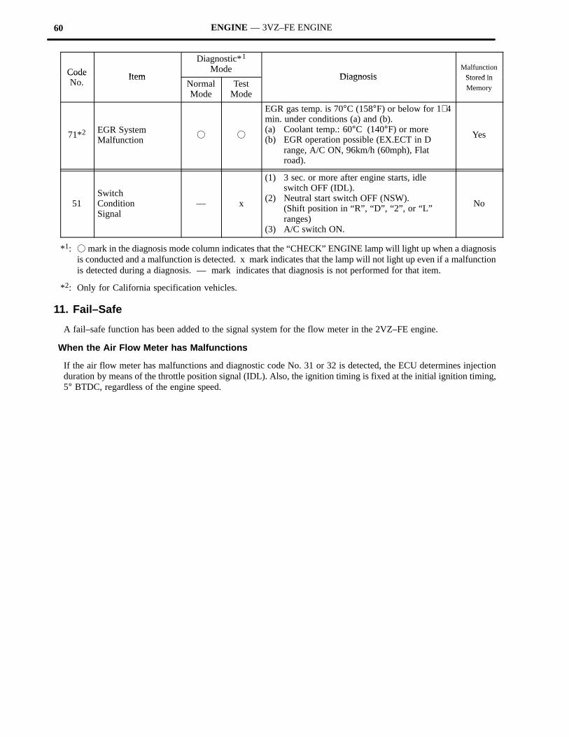
*1: � mark in the diagnosis mode column indicates that the “CHECK” ENGINE lamp will light up when a diagnosisis conducted and a malfunction is detected. x mark indicates that the lamp will not light up even if a malfunctionis detected during a diagnosis. — mark indicates that diagnosis is not performed for that item.
*2: Only for California specification vehicles.
11. Fail–Safe
A fail–safe function has been added to the signal system for the flow meter in the 2VZ–FE engine.
When the Air Flow Meter has Malfunctions
If the air flow meter has malfunctions and diagnostic code No. 31 or 32 is detected, the ECU determines injectionduration by means of the throttle position signal (IDL). Also, the ignition timing is fixed at the initial ignition timing,5° BTDC, regardless of the engine speed.
Related Documents