VIRGINIA DTVISION OF MINERAL RESOURCES PUBLICATION II9 PROCEEDINGS 26TIJ FORUM ON THE GEOLOGY OF INDUSTRIAL MINERALS May 14-L8, 1990 Edited by Palmer C. Sweet COMMONWEALTH OF VIRGINIA DEPARTMENT OF MINES, MINERALS AND ENERGY DIVISION OF MINERAL RESOURCES CHARLOTTESVILLE. VA 1992

Welcome message from author
This document is posted to help you gain knowledge. Please leave a comment to let me know what you think about it! Share it to your friends and learn new things together.
Transcript
VIRGINIA DTVISION OF MINERAL RESOURCESPUBLICATION II9
PROCEEDINGS
26TIJFORUM ON THE GEOLOGY OF INDUSTRIAL MINERALS
May 14-L8, 1990
Edited by
Palmer C. Sweet
COMMONWEALTH OF VIRGINIA
DEPARTMENT OF MINES, MINERALS AND ENERGYDIVISION OF MINERAL RESOURCES
CHARLOTTESVILLE. VA1992
VIRGINIA DTVISION OF MINERAL RESOURCESPUBLICATION II9
PROCEEDINGS
26TIdFORUM ON THE GEOLOGY OF INDUSTRIAL MINERALS
May 14-18, 1990
Edited by
Palmer C. Sweet
COMMOI\-WEALTH OF VIRGINIA
DEPARTMENT OF MINES, MINERALS AND ENERGYDIVISION OF MINERAL RESOURCES
CHARLOTTESVILLE, VA1992
DEPARTMENT OF MINES, MINERALS AND ENERGYRICHMOND, VIRGIMAO. Gene Dishner. Director
Copyright 1992, Commonwealth of Virginia
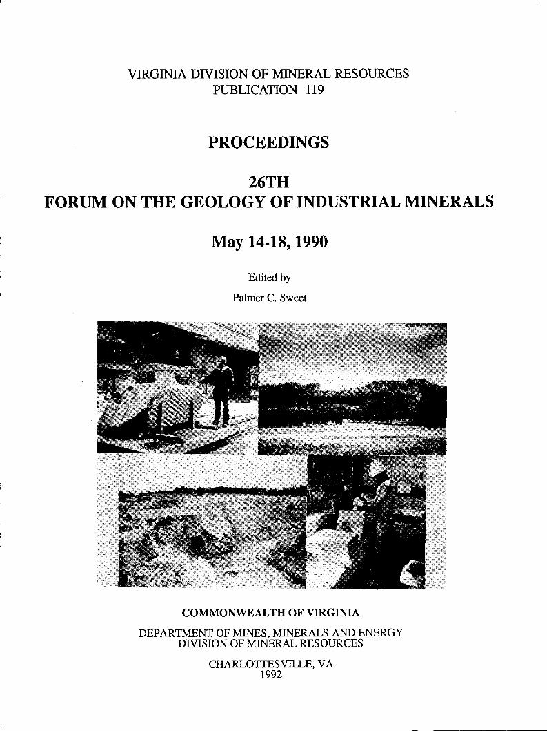
FRONT COVER: Sites and activities at the quarry operations visited during the 26th Forum on the Geology of Indusrrial Minerals,May 14-18, 1990, Charlotiesville, Virginia. Upper left photograph, clockwise: sawing soapstone at The New Alberene StoneCompany,Schuyler,NelsonCounty; kyanite-bearingquartzileridgeofWillisMountain,viewtonorth-northeast,KyaniteMiningCorporation, Dillwyn, Buckingham County; producing slate shingles at Lesueur Richmond Slate Corporation, ArvonialBuckingham County; mining vermiculite from open pit at Virginia Vermiculite, Ltd., Louisa County (Photogmphs by WilliamF. Giannini, David A. Hubbard, Jr., and Palmer C. Sweet).
hinting jointly funded by the Commonwealth of Virginia and the 26th Forum on ttre Geology of Indusrial Minerals.
VIRGINIA DTVISION OF MINERAL RESOURCESPUBLICATION TT9
PROCEEDINGS
26TIJFORUM ON THE GEOLOGY OF INDUSTRIAL MINERALS
May 14-18, 1990
Edited by
Palmer C. Sweet
COMMONWEALTH OF VIRGINIA
DEPARTMENT OF MINES, MINERALS AND ENERGYDIVISION OF MINERAL RESOURCES
CHARLOTTESVILLE, VAt992
Palmer C. SweetRonaldP. GeitgeySamuel W. Berkheiser, Jr.DaleW. ScottThomas E. Newman
Ken Santini
Palmer C. SweetWilliam F. GianniniParicia W. MarshallStanley S. JohnsonElizabeth V. M. CampbellRoy S. SitesGeraldP. Wilkes
FORI.JM STEERING COMMITTEE1990
LOCAL PLANNING COMMITTEE
ChairmanPast Chairman
Elected in 1990
General ChairmanField Trip ChairmanConference SecretaryTechnical Sessions
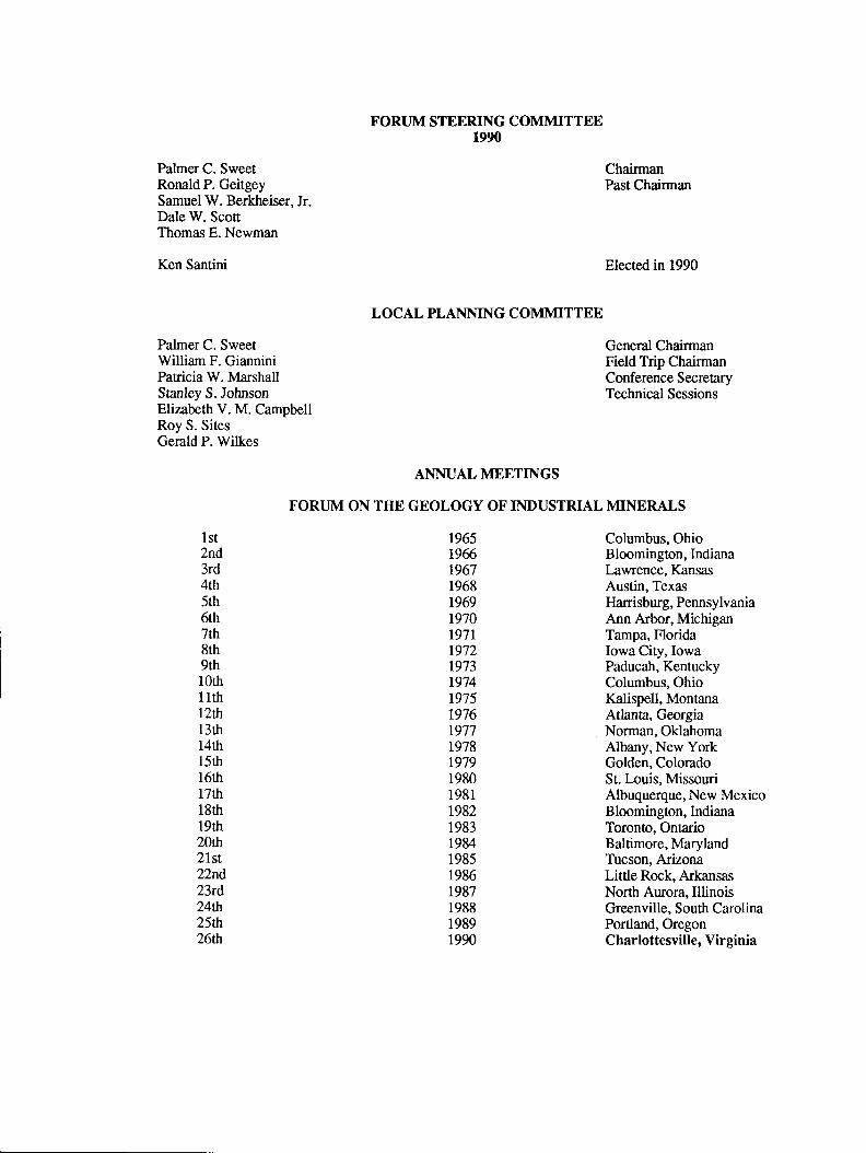
Columbus, OhioBloomington, IndianaLawrence, KansasAustin, TexasHarrisburg, PennsylvaniaAnn Arbor, MichiganTampa, FloridaIowa City, IowaPaducah, KentuckyColumbus, OhioKalispell, MontanaAdana, GeorgiaNorman, OklahomaAlbany, New YorkGolden, ColoradoSt. Louis, MissouriAlbuquerque, New MexicoBloomington, IndianaToronlo, OntarioBaltimore, MarylandTucson, ArizonaLittle Rock, ArkansasNorth Aurora,IllinoisGreenville, South CarolinaPortland, OregonCharlottesville, Virginia
lst2nd3rd4rh5th6rh7rh8th9th1Orh
1 1rh
lzth13th14th15rlt16th17rlt18thl9rtr20th21st22nd23rd,24th25th26th
ANNUAL MEETINGS
FOR{JM ON THE GEOLOGY OF INDUSTRIAL N{INERALS
19651965196719681969r970r97lr972r973r974r975r976r9771978r9'791980198119821983L984198519861987198819891990
FOREWORD
The 26th Forum on the Geology of Indusrial Minerals was held lvlay 14-18, 1990 in Charlottesville, Virginia. The forumwassponsoredbyttreVirginiaDivisionofMineralResources,DepartrnentofMines,MineralsandEnergy. Themeetingconsistedof 3 days of technical sessions and 2 days of field trips to dimension slate and soapstone operations, the only domestic kyaniteproducer and a vermiculite operation. Two excursions CI Natural Bridge and to view dinosaur footprints in Mesozoic age
sediments as well as 3 separate spouse events were provided. A total of 200 registered for the meeting.
Themeetingwaskickedoffwithapanelconsistingof governmentpersonnelfrom ttreStateof Vfuginia,U.S. Bureauof Minesand U.S. Geological Survey. They presented their agency's role in industrial minerals and then fielded questions from theaudience. Presentations during the technical sessions consisted of ppers on aggegates, brucite, carbonates, clay, dimensionstone, high-silicaresources, karst deposits, kyanite, pegmatites, slate, soapstone, and vermiculite. Papers on the use ofcompufento compile and disseminate resource data, aid in computing reserves, developing a mining plan and planning a reclamationprogram were also presented. Additional presentations were given on the role of regulatory agencies with the mining industryand the image of the mining industry.
Financial support for the meeting was received from lrsueur Richmond Slale Corporation, Luck Stone Corporation, NorthAmerican Exploration, Inc., Virginia Vermiculite, Ltd. and W.W. Boxley Company as well as from the Society of EconomicGeologist's Foundation, Inc.
This proceedings volume contains papers and abstracts of presentations at the forum. Only a "light" edit has been done onthe papers submitted for this proceedings volume.
Palmer C. Sweet
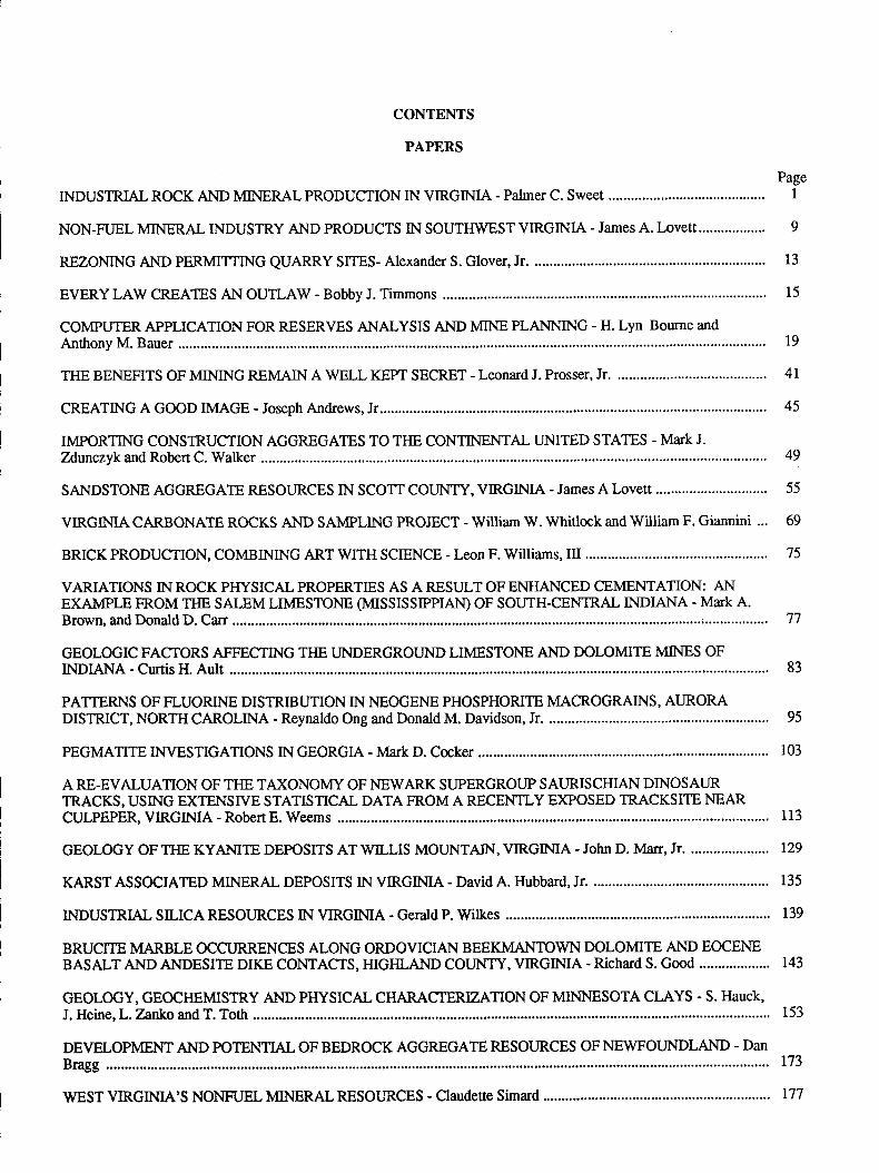
CONTENTS
PAPERS
INDUSTRIAL ROCK AND MINERAL PRODUCTION IN VIRGIMA - Palmer C. Sweet
NON-FUEL MINERAL INDUSTRY AND PRODUCTS IN SOUTHWEST VIRGINIA - JAMES A. LOVEtt.....
REZONING AND PERMITTING QUARRY SITES- Alexander S. Glover, Jr. ...............
EVERY LAW CREATES AN OUTLAW - Bobby J. Timmons
COMPUTER APPLICATION FOR RESERVES ANALYSIS AND MINE PLANNING - H. Lyn Bourne and
TIIE BENEFITS OF MINING REMAIN A WELL KEPT SECRET - Leonard J. Prosser, Jr. ...............
CREATING A GOOD IMAGE - Joseph Andrews, Jr..................
IMPORTING CONSTRUCTION AGGREGATES TO TIIE CONTINENTAL UNITED STATES - MATK J.
SANDSTONE AGGREGATE RESOURCES IN SCOTT COUNTY, VIRGINIA - James A Love[t
VIRGINIA CARBONATE ROCKS AND SAMPLING PROJECT - William W. Whitlock and William F. Giannini ...
BRICK PRODUCTION, COMBIMNG ART WITH SCIENCE - Leon F. Williams, III ................
VARIATIONS IN ROCK PHYSICAL PROPERTIES AS A RESULT OF ENHANCED CEMENTATION: ANEXAMPLE FROM THE SALEM LTMESTONE (MrSSrSSrPPrAr\o OF SOUTH-CENTRAL INDIANA - Mark A.
GEOLOGIC FACTORS AIIFECTING T}IE UNDERGROUND LIMESTONE AND DOLOMITE MINES OF
PATTERNS OF FLUORINE DISTRIBUTION IN NEOGENE PHOSPHORITE MACROGRAINS, AURORADISTRICT, NORTH CAROLINA - Reynaldo Ong and Donald M. Davidson, Jr. ..............
PEGMATITE IIWESTIGATIONS IN GEORGIA - Mark D. Cocker
A RE.EVALUATION OF TIIE TAXONOMY OF NEWARK SUPERGROUP SAURIS CHIAN DINOSAURTRACKS, USING EXTENSIVE STATISTICAL DATAFROMARECENTLY E)GOSED TRACKSITE NEARCULPEPER, VIRGIMA - RobertE. Weems
GEoLoGYoFT}IEKYANITEDEPosITsATwILLISMoUNTAIN,VIRGINIA.JohnD.Marr,Jr.
KARST ASSOCIATED MINERAL DEPOSITS IN VIRGINIA - David A. Hubbard, Jr. ...............
INDUS]RIAL SILICA RESOURCES IN VIRGIMA - Gerald P. Wilkes
BRUCITE MARBLE OCCURRENCES ALONG ORDOVICIAN BEEKMANTOWN DOLOMITE AND EOCENEBASALT AND ANDESITE DIKE CONTACTS, HIGHLAND COUNTY, VIRGINIA - Richald S. GOOd
GEOLOGY, GEOCI{EMISTRY AND PHYSICAL CHARACTERZATION OF MINNESOTA CLAYS . S. HAUCK,
DEVELOPMENT AND POTENTIAL OF BEDROCK AGGREGATE FGSOURCES OF NEWFOUNDLAND - DAN
WEST VIRGINIA'S NONFTJEL MINERAL RESOURCES - Claudese Simard
19
4l
45
PageI
9
13
15
49
55
69
75
77
83
95
103
113
r29
135
r39
r43
153
r73
177
ABSTRACTS
PageTHE ROLE OF T}IE U.S. BUREAU OF MINES IN TI{E DEVELOPMENT AND REGULATION OFINDUSTRIAL MINERALS - Atdo
OVERVIEW OF DEPARTMENT OF MINES, MINERALS AND ENERGY REGULATORY PROGRAM FORMETALA{ONMETAL NOMENCLATURE - Robert E. Morgan and Gary E. Bamey ............ 1g5
NORTH CAROLINA INDUSTRIAL MINERALS: COMMODITTES, APPLIED MINERAL RESEARCH,REGULATION, AND RESOURCES TO ASSIST MINERAL DEVELOPMENT - Jeffrey C. Reid................................ 185
U.S. GEOLOGICAL SURVEY'S MINERAL RESOURCE DATA SYSTEM - Raymond E. Arndr ........... 186
DEVELOPMENTS AND OPPORTUNITIES IN INDUSTRIAL CARBONATES ON NEWFOUNDLAND'SGREATNORTI{ERNPENINSIJLA - AmbroseF. Howse ............ 186
DIMENSION STONE IN NEWFOLINDLAND - James R. Meyer ...................... l8Z
I99I FORUM ON THE GEOLOGY OF INDUSTRIAL MINERALS. ALBERTAERITISH COL{JMBIA,CANADA - Wylie N. Hamilton and Z. Danny Hora ........... ............ lgz
INDUSTRIAL ROCK AND MINERAL PRODUCTION IN VIRGINIA
Palmer C. SweetVirginia Division of Mineral Resources
P. O. Box 3667Charlottesvill e, Y r ginia 22903.
ABSTRACT
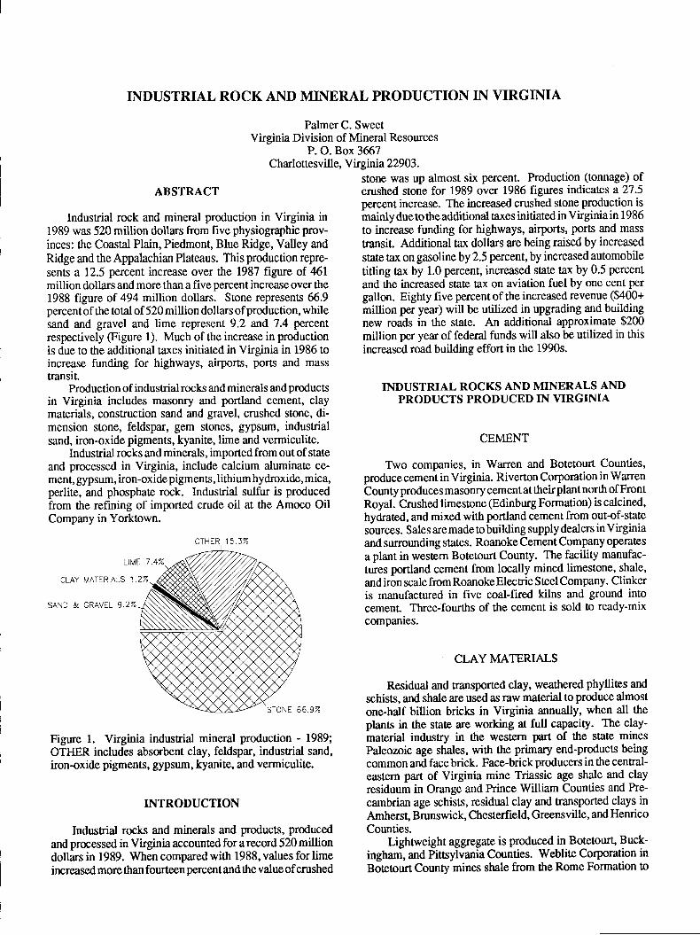
Indusrial rock and mineral production in Virginia in1989 was 520 milton dollars from five physiographic prov-inces: the Coastal Plain, Piedmont, Blue Ridge, Valley andRidge and the Appalachian Plateaus. This production repre-
sents a 12.5 percent increase over the 1987 figure of 461million dollars and more than a five percent increase over the1988 figure of 494 million dollars. Stone represents 65.9percentof the total of 520 million dollars ofproduction, whilesand and gravel and lime represent 9.2 and 7.4 percent
respectively (Figure 1). Much of the increase in productionis due to ttre additional taxes initiated in Virginia in 1986 toincrease funding for highways, airports, ports and masstransit.
Production of industrial rocks and minerals and productsin Virginia includes masonry and ponland cement, claymaterials, construction sand and gravel, crushed stone, di-mension stone, feldspar, gem stones, gypsum, industrialsand, iron-oxide pigments, kyanite, lime and vermiculite.
Indusrial rocks and minerals, imported from out of state
and processed in Virginia, include calcium aluminate ce-ment, gypsum, iron-oxide pigments, lithium hydroxide, mica,perlite, and phosphate rock. IndusEial sulfur is producedfrom the refining of imported crude oil at ttre Amoco OilCompany in Yorktown.
CLAY MATERLALS 1.
SAND & GRAVEL 9.2%
Figure 1. Virginia indusrial mineral production - 1989;OTI{ER includes absorbent clay, feldspar, industrial sand,iron-oxide pigments, gypsum, kyanite, and vermiculite.
INTRODUCTION
Indusnial rocks and minerals and products, producedand processed in Virginia accounted for arecord 520 milliondollars in 1989. When compared with 1988, values for limeincreased more than fourteen percent and the value of crushed
stone was up almost six percent. Production (tonnage) ofcrushed stone for 1989 over 1986 figures indicates a 27.5percent increase. The increased crushed stone production ismainly due to the additional taxes initiated in Virginia in 1986
!o increase funding for highways, airports, ports and mass
transit. Additional tax dollars are being raised by increased
state tax on gasoline by 2.5 percent, by increased automobile
titling tax by 1.0 percent, increased state tax by 0.5 percent
and the increased state tax on aviation fuel by one cenl per
gallon. Eighty five percent of the increased revenue ($a00+
million per year) will be utilized in upgrading and buildingnew roads in the state. An additional approximate $200million per year of federal funds will also be utilized in thisincreased road building effort in the 1990s.
INDUSTRIAL ROCKS AND MINERALS ANDPRODUCTS PRODUCED IN VIRGINIA
CEMENT
Two companies, in Warren and Botetourt Counties,produce cement in Virginia. Riverton Corporation in WarrenCounty produces masonry cement at theirplant north of FrontRoyal. Crushed limestone @dinburg Formation) is calcined,hydrated, and mixed with portland cement from out-of-statesources. Sales are made to building supply dealers in Virginiaand surrounding states. Roanoke Cement Company operates
a plant in western Botetourt County. The facility manufac-
tures portland cement from locally mined limestone, shale,
and iron scale from Roanoke Elecric Steel Company. Clinkeris manufactured in five coal-fired kilns and ground intocement. Three-fourths of the cement is sold to ready-mixcompanies.
CLAY MATERIALS
Residual and transported clay, weathered phyllites and
schists, and shale are used as raw material to produce almostone-half billion bricks in Virginia annually, when all theplants in the state are working at full capacity. The clay-material industry in the western part of ttre state mines
Paleozoic age shales, with the primary end-products beingcommon and facebrick. Face-brickproducers in the central-eastern pafi of Virginia mine Triassic age shale and clayresiduum in Orange and Prince William Counties and Pre-
cambrian age schists, residual clay and transported clays inAmherst, Brunswick, Chesterfield, Greensville, and Henrico
Counties.Lightrveight aggregate is produced in Botetourt, Buck-
ingham, and Pittsylvania Counties. Weblite Corporation inBotetourt County mines shale from the Rome Formation to
oTHtR 1 5.3%
VIRGIMA DIVISION OF MINERAL RESOURCES
prodlce lighnveight aggregate by the sintering process, usingsemi-anthracite waste coal from MontgomeryCounty to fuethe kilns . They utilize about I 00 tons of coal per day
-o yield
a lightweight-product having a weight as low as 3l lbft3for5 /16 to 314 nch particle sizes. Solite Corporarion in norrhemBuckingham County uses the Arvonia Slate of Ordovicianage to produce lightrveight aggregate. Triassic age shale isused by Virginia Solite Company southwest of Danville,Pittsylvania County, to obtain a similar product.
Clay from ttre Cold Spring kaolin deposit in sourheasrern
,Augusta County is intermittently utilized by James RiverLimestone Company,Inc. to mix with the crushed dolomiteat their operation near Buchanan, Botetourt County to pro-duce various grades of filler material and as an ingrbdient inwhite cemenl
Bennett Mineral Company in the Walkerton area of Kingand Queen County in eastern Virginia mines and processeimontmorillonite clay to produce an indusnial and sanitary
*ro1t"ry. The facility uses wood wastes as a plant fuel to drythe clay in a rotary kiln.
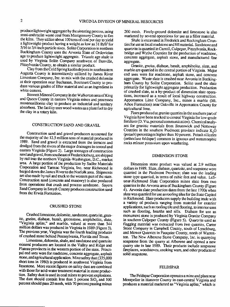
CONSTRUCTION SAND AND GRAVEL
Construction sand and gravel producers accounted for!!e lajority of the 12.5 million rons of marerial produced in1989. Sand and gravel is extracted from the terraces anddredged from the rivers of the major drainages in central andeastern Virginia (Figure 2). large tonnages of constructiongandqd gravel, from southeastofFredericksburg, areshippedby rail ino the northern Virginia-Washington, b.C., marketarea. A large portion of the production by Sadler MaterialsCorporation and Tarmac Virginia, Inc. near Richmond isbarged down the James River to the Nodolk area. Shipmentsare also madebyrail and ruckto *rewesternpartof the state.ConsEuction sand (concrete and masonry) ii also producedf_rom operations that crush and process sandstone-. SayersSand Company in Smyth County produces construction sandfrom the Erwin Formation.
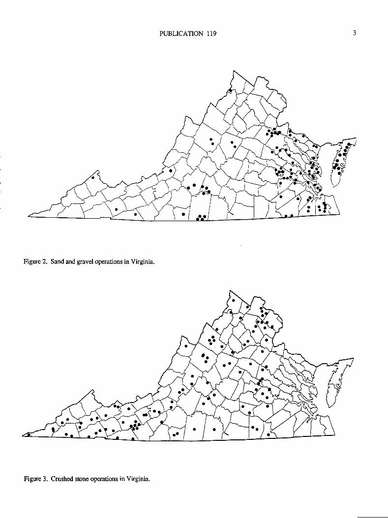
CRUSI{ED STONE
Crushed limestone, dolomite, sandstone, quartzite, gran-
iF" gneiss, diabase, basalt, greenstone, amphibolite, ilate,"Virginia aplite," and marble, valued at more than 344million dollars was produced in Virginia in 1989 (Figure 3).The previous year, Virginia was the fourth leading pioducerof crushed stone behind Pennsylvania, Florida and fexas.
Limestone, dolomite, shale, and sandstone and quartzitemineral producers are located in the Valley and Ridge andPlateau provinces in the weslem portion of ihe state. princi-pal end uses were for roadstone, concrete aggregate, asphaltstone, andagriculnral application. Minesafety dust (335,000short tons in 1980) is produced in southwest Virginia fromlimestone. More recent figures on safety dust are combinedwith ttrose foracid-water treatment material in stone produc-tion. Safety dust is used in coal mines to prevent expiosions.The dust should contain less rhan 5 percent SiO and 100percent should pass 20 mesh, with 70 percent passing minus
200 mesh. Finely-ground dolomite and limestone is alsomarketed by several operations for use as a filler material.
Shale is excavated in Frederick and Rockingham Coun-ties for use as local roadstone and fill material. Sandsone andquartzito is quarried in Carroll, Culpeper, Pittsylvania, Rock-bridge and Wythe Counties for the production of roadstone,concrete aggregate, asphalt stone, and manufactured fineaggregate.
Granite, gneiss, diabase, basalt, amphibolite, slate, andmarble are quanied in the cenftal portion of Virginia. Majorend uses were for roadstone, asphalt stone, and concreteaggegate. Waste slate is crushed near Arvonia in Bucking-ham County by Solite Corporation. Solite used the slateprimarily for lighweight aggegat€ production. productionof crushed slate, as a by-product of dimension slate opera-tions, increased as a result of local highway construction.Appomattox Lime Company, Inc., mines a marble (Mt.Athos Formation) near Oakville in Appomattox County foragricultural lime.
Fines produced at granite quarries in the southern part ofVirginia have been trucked to central Virginia for low-gradefertilizer (D. Via, personal communication). Chemical analy-ses for granitic materials from Brunswick and NottowayCounties in the southern Piedmont province indicate I(O(potash) percentages higher rhan 10 percent. Potash silicaies(orthoclase feldspar) common in igneous and metamorphicrocks release potassium upon weathering.
DIMENSION STONE
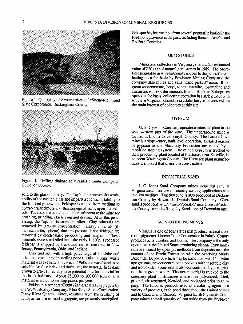
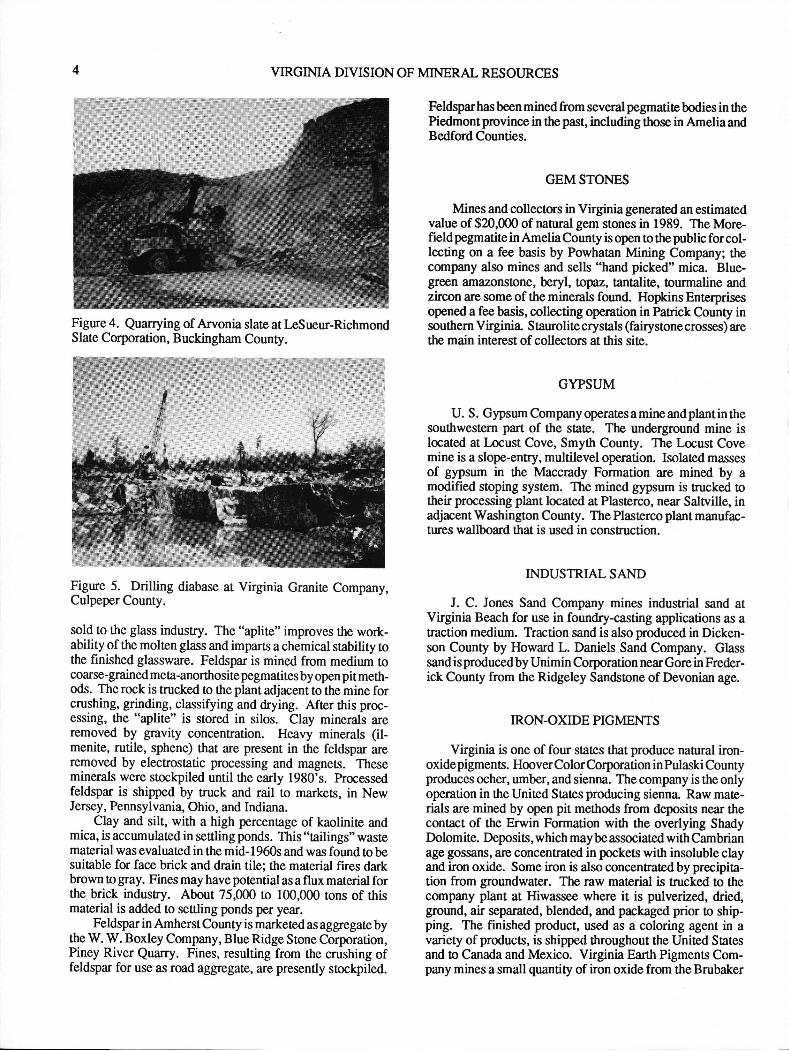
Dimension s[one product was valued at 2.9 milliondollars in 1989. Slate, diabase, quartzite, and soapstone werequarried in the Piedmont Province; slate was ttre leadingstone type quarried, in terms of cubic feet and value. LpS-ueur-Richmond Slate Corporation mines slate from twoquarries in the Arvonia area of Buckingham County (Figure4). Arvonia slate production dates from the late 1700s whenslate was quarried for use as roofing tiles for the State Capitolin Richmond. Slate producers supply the building rade witha variety of products ranging from material for exteriorapplications, such as roofing tile and flooring, to interior usessuch as flooring, hearths and sills. Diabase for use asmonument stone is produced by Virginia Granite Companyin southern Culpeper County (Figure 5). Quartzite used asflagging material was extracted from two quarries, CarterStone Company in Campbell County, south of Lynchburg,and Mower Quarries in Fauquier County, north of Warren-ton. The New Alberene Stone Company, Inc. is quarryingsoapstone from the quarry at Alberene and opened a newquarry site in late 1989. Their products include soapstonefireplaces, woodstoves, cooking ware, and otherproducts ofsolid soapstone.
FELDSPAR
The Feldspar Corporation operates a mine and plant nearMonpelier in Flanover County in east-cenEal Virginia andproduces a material marketed as "Virginia aplite," which is
PUBLICATION 119
Figure 2. Sand and gravel operations in Virginia.
Figure 3. Crushed stone operations in Virginia.
VIRGIMA DIVISION OF MINERAL RESOURCES
Figure 4. Quarrying of Arvonia slate at LeSueur-RichmondSlate Corporation, Buckingham County.
{#*iti" ,,
Figure 5. Drilling diabase ar Virginia Granite Company,Culpeper County.
sold to the glass industry. The "aplite" improves the work-ability of the molten glass and imparts a chemical stability tothe finished glassware. Feldspar is mined from medium tocoarse-grained meta-anorthosite pegmatites by open pit meth-ods. The rock is trucked to the plant adjacent to the mine forcrushing, grinding, classifying and drying. After this proc-essing, the "aplite" is stored in silos. Clay minerals areremoved by gravity concentration. Heavy minerals (il-menite, rutile, sphene) that are present in the feldspar areremoved by electrostatic processing and magnets. Theseminerals were stockpiled until the early 1980's. processedfeldspar is shipped by truck and rail to markets, in NewJersey, Pennsylvania, Ohio, and Indiana.
Clay and silt, with a high percentage of kaolinite andmica, is accumulated in settling ponds. This "tailings" wastematerial was evaluated in the mid- 1960s and was found to besuitable for face brick and drain tile; the material fires darkbrown !o gray. Fines may have potential as a flux material forthe brick industry. About 75,ffi0 to 1@,000 tons of thismat€rial is added to settling ponds per year.
Feldsparin Amherst County is marketed as aggregate bythe W. W. Boxley Company, Blue Ridge Stone Corporation,Piney River Quarry. Fines, resulting from the crushing offeldspar for use as road aggregate, are presently stockpiled.
Feldsparhas been mined from several pegmatite bodies in tlePiedmont province in the past, including those in Amelia andBedford Counties.
GEMSTONES
Mines and collectors in Virginiagenerated an estimatedvalue of $20,000 of natural gem stones in 1989. The More-field pegmatite in Amelia County is open to the public for col-lecting on a fee basis by Powhatan Mining Company; thecompany also mines and sells "hand picked" mica. Blue-grcen amazonstone, beryl, topaz, tantalite, tourmaline andzircon are some of the minerals found. Hopkins Enterprisesopened a fee basis, collecting operation in Patrick County insouthern Virginia. Staurolite crystals (fairystone crosses) arethe main interest of collectors at this site.
GYPSUM
U. S. Gypsum Company operates a mine and plant in thesouthwestern part of the sate. The underground mine islocated at l,ocust Cove, Smyth County. The Locust Covemine is a slope-entry, multilevel operation. Isolated massesof gypsum in the Maccrady Formation are mined by amodified stoping system. The mined gypsum is trucked !otheir processing plant located at Plasterco, near Sahville, inadjacent Washington County. The Plasterco plant manufac-tures wallboard that is used in construction.
INDUSTRTAL SAND
J. C. Jones Sand Company mines industrial sand atVirginia Beach for use in foundry-casting applications as atraction medium. Traction sand is also produced in Dicken-son County by Howard L. Daniels Sand Company. Glasssand is produced by Unimin Corporation near Gore in Freder-ick County from the Ridgeley Sandstone of Devonian age.
IRON-OXIDE PIGMENTS
Virginia is one of four states that produce natural iron-oxide pigments. Hoover Color Corporation inPulaski Countyproduces ocher, umber, and sienna. The company is the onlyoperation in ttre United States producing sienna. Raw mate-rials are mined by open pit methods from deposits near thecontact of the Erwin Formation with the overlying ShadyDolomite. Deposits, which may be associated with Cambrianage gossans, are concentrated in pockets with insoluble clayand iron oxide. Some iron is also concentrated by precipia-tion from groundwater. The raw material is trucked to thecompany plant at Hiwassee where it is pulverized, dried,ground, an reparated. blended, and packaged prior to ship-ping. The finished product, used as a coloring agent in avariety of products, is shipped throughout the United Statesand to Canada and Mexico. Virginia Earth Pigments Com-pany mines a small quantity of iron oxide from the Brubaker
PUBLICATION 1I9
# I mine in southeastern Wythe County. The majority of thismaterial is sold to Hoover Color Corporation.
KYANITE
Kyanite, an aluminum silicate, was first produced inPrince Edward County in the 1920s. Since September, I 986,Virginia is the only state producing kyanite. The majority ofthe world's kyanite, is produced by Kyanite Mining Corpo-ration from their deposit in Buckingham County. The com-pany produces a concentrate grade of a maximum of 61.8percent alumina and a minimum iron content of 0. I 6 percent.Calcined kyanite is converted to mullite at temperaturesgreater than 3000 degrees Fahrenheit The mullite is a super-dutyrefractory with apyrometric cone equivalentof 36 o 3?.Products, which are sold in 35, 48, 100, 200, and 325 meshsizes, are usedin the refractory, ceramic, glass, metallurgical,and foundry industries. Mullite aids ceramics and glass meltsto resist cracking, warping, slagging, and deforming fromhigh temperatures.
Kyanite Mining Corporation operatos two surface minesand processing plants in central Buckingham County, one atWillis Mountain and one at East Ridge. Kyanite-bearingquartzite is quarried from ope.n pits, run through primarycrushers, through a log washer !o remove clay, and onto theclassifiers to remove some kyanite. The material then passesthrough a rod mill which reduces it to minus 35-mesh size,and then through frottr flotation cells so kyanite can beskimmed off. The kyanite is dewatered and then dried; thehigh temperature of the drier converts the sulfide mineralsthat are present in the quartzite o oxides. Pyrite is convertedto ferrous iron oxide (F"rq) or magnetite, which is thenremoved by magnetic separators and stockpiled.
The Willis Mountain Plant processes the raw kyanitewhich is then trucked to the East Ridge facility for calcining.Mullite is ground and bagged at the Dillwyn Plant and rawkyanite is ground and bagged at Willis Mountain.
Approximately 40 percent of the production is shippedtt[ough the port of Hampton Roads to worldwide customers.The company also markets a by-product sand obtained fromthe processing of kyanite. The sand is sold for golf course,masonry, and concrete sand, and other applications.
LIME
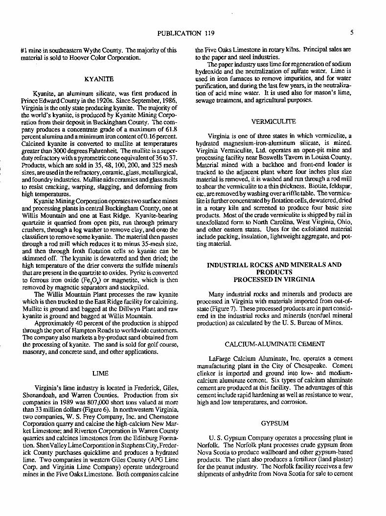
Virginia's lime industry is located in Frederick, Giles,Shenandoah, and Warren Counties. Production from sixcompanies in 1989 was 807,000 short tons valued at morcthan 33 million dollars (Figure 6). In northwestern Virginia,two companigs, W. S. Frey Company, Inc. and ChemstoneCorporation quarry and calcine the high-calcium New Mar-ket Limestone; and Riverton Corporation in Warren Countyquarries and calcines limestones from the Edinburg Forma-tion. ShenValley LimeCorporation in Stephens City, Freder-ick County purchases quicklime and produces a hydratedlime. Two companies in western Giles County (APG LimeCorp. and Virginia Lime Company) operate undergroundmines in the Five Oaks Limestone. Both companies calcine
the Five Oaks Limestone in rotary kilns. hincipal sales are
to the paper and steel industries.Thepaper industry uses lime forregeneration of sodium
hydroxide and the neutralization of sulfate water. Lime isused in iron fumaces to remove impurities, and for waterpurification, and during the last few years, in the neutaliza-tion of acid mine water. It is used also for mason's lime,sewage treatment, and agriculnrral purposes.
VERMICULNE
Vnginia is one of ttree states in which vermiculile, ahydrated magnesium-iron-aluminum silicate, is mined.Virginia Vermiculite, Ltd. operates an open-pit mine andprocessing facility near Boswells Tavem in Louisa County.lvlaterial mined with a backhoe and front+nd loader istrucked to the adjacent plant where four inches plus sizematerial is removed, it is washed and run through a rod millto shear the vermiculite !o a thin thickness. Biotite, feldspar,etc . are removed by washing over a riffle table. The vermicu-lite is further concentrated by flotation cells, dewatered, driedin a rotary kiln and screened to produce four basic sizeproducts. Most of the crude vermiculite is shipped by rail inunexfoliated form to North Carolina, West Virginia, Ohio,and other eastern states. Uses for the exfoliated materialinclude packing, insulation, lightweight aggregate, and pot-ting material.
INDUSTRIAL ROCKS ANDMINERALS ANDPRODUCTS
PROCESSED IN VIRGIMA
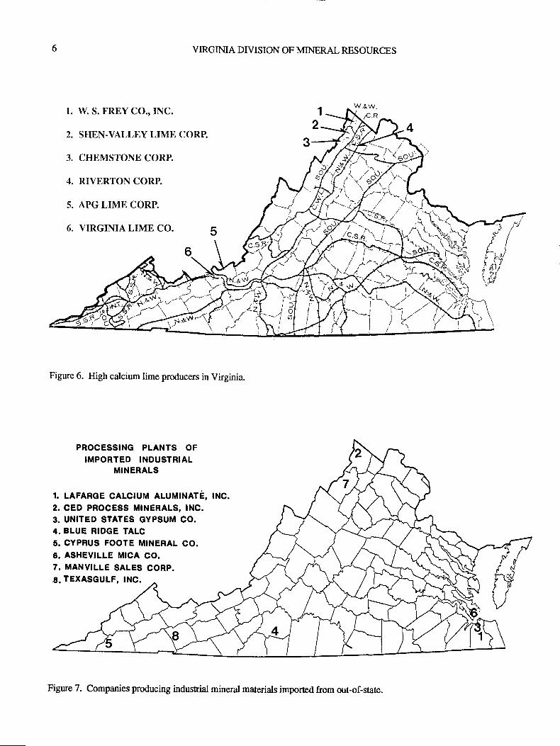
Many indusrial rocks and minerals and products areprocessed in Virginia wittr materials imported from out-of-state (Figure 7). These processed products are in part consid-ered in the indusrial rocks and minerals (nonfuel mineralproduction) as calculated by the U. S. Bureau of Mines.
CALCIUM-ALUMINATE CEMENT
LaFarge Calcium Aluminale, Inc. operates a cementmanufacturing plant in the City of Chesapeake. Cementclinker is imported and ground into low- and medium-calcium aluminate cement. Six types of calcium aluminatecement are produced at tiris facility. The advantages of thiscement include rapid hardening as well as resistance to wear,high and low temperatutes, and corrosion.
GYPSUM
U. S. Gypsum Company operates a processing plant inNorfolk. The Norfolk plant processes crude gypsum fromNova Scotia to produce wallboard and other gypsum-basedproducts. The plant also produces a fertilizer (land plaster)for the peanut industry. The Norfolk facility receives a fewshipments of anhydrite from Nova Scotia for sale to cement
VIRGINIA DIVISION OF MINERAL RESOI]RCES
1. W. S. FREY CO.,INC.
2. SHEN-VALLEY LIME CORP.
3. CHEMSTONE CORP.
4. RIVERTON CORP.
5. APG LIME CORP.
6. VIRGINIA LIME CO.
)r
--7\-J/\Jh'/'
\t
\1.r\\r.)\\ \tt\.. vtt\
\i
Figure 6. High calcium lime producers in Virginia.
PROCESSING PLANTS OF
IMPORTED INDUSTRIALMINERALS
1. LAFARGE CALCTUM ALUMTNATE, tNC.
2. CED PROCESS MINERALS, INC.3. UNITED STATES GYPSUM CO.4. BLUE RIDGE TALC5. CYPRUS FOOTE MINERAL CO.6. ASHEVILLE MICA CO,7. MANVILLE SALES CORP.6. TEXASGULF, INC.
/,{r^.),
h:,"Y
./^ -,".r 7-\$L1-.^
f* ffi1n,",'Yt..*'/"x\ _r \'-1,. I.1 i!z' ii / 7. '/
Figure 7. Companies producing industial mineral materials imported from out-of-state.
PUBLICATION 119
manufacturers. The anhydrite is used as a source of sulfi.r inproducing cement clinker.
INDUSTRIAL SAND
CED Process Minerals, Inc., Gore, inFrederickCounty,recrystallizes purchased sand in a rotary kiln to producecristobalite, which is marketed as a fine grit @gure 8).
Figure 8. Cristobalite processing plant of CED ProcessMinerals, Inc. at Gore, Frederick County.
IRON.OXIDE PIGMENTS
Blue Ridge Talc Company, Inc. imports crude iron-oxide pigments from a supplier near the Great Lakes. Thepigments are ground and calcined for use in paints andfertilizers, and forcementand mortarcoloring. Their marketsare both domestic and foreign.
LITHIUM HYDROXIDE
Cyprus Foote Mineral Company purchases lithium car-bonate produced from brines in Nevada using calcium hy-droxide from various sources to produce lithium hydroxide attheir Sunbright plant in Scott County. Lithium hydroxide isused in multipurpose gease applications. In the past,lime-stone from an underground mine at the Sunbright site wasutilized in the manufacturing process and a calcium carbon-ate precipitate was formed as a waste product. This wastematerial remains on the site and may have a potential use. Theapproximate analysis of the material is 43-50percentCaCQ,3-6 percent Ca(O$r, and 40-48 percent water.
MICA
Asheville Mica Company and an affiliate, Mica Com-pany of Canada, process mica at facilities in Newport News.The crude mica is imported from lvladagascar and India.
Asheville Mica Company produces fabricated plate-micaand the Mica Company of Canada uses splittings from theAsheville operation toproducereconstitutedplate-mica. Micahas been produced in the past from pegmatite bodies inseveral counties in Virginia, including Amelia, Henry, andPowhatan. Mica is presently being "hand picked" in AmeliaCounty.
PERLITE
Manville Sales Corporation ope.rates a plant at Wood-stock in Shenandoah County to expandperlite (volcanic glass
with high water content and "onion-skin" appearance) ob-tained from Grants, New Mexico. Expanded perlite is usedin the manufacture of roof insulationboard whichis marketedthroughout the eastern United States.
PHOSPHATE
TexasGulf,Inc. ships phosphate rock from its lre Creekoperation in North Carolina to Glade Spring, WashingtonCounty. The raw material is then transported by truck to ttreTexasGulf plant in Saltville, Smyth County. A coal-firedrotary kiln is used to defluorinate the phosphate rock. Theproduct is marketed as apoultry and animal feed supplementin the southern and midwestern states.
SLILF[.]R
Elemental sulfw is recovered from hydrogen sulfide gas
by the Claus process during crude-oil refining by Amoco OilCompany. The refinery is adjacent to the York River, nearYorktown. Crude oil is heated in a furnace and fed underpressure into a cylinder where it vaporizes, expands, andcondenses into liquid. Hydrogen sulfide is produced and isconverted into elemental sulfur. About 50 tons of sulfur isproduced per day and is marketed to a buyer for use infertilizer.
PUBLICATION 119
manufacture.rs. The anhydrite is used as a source of sulfur inproducing cement clinker.
INDUSTRIAL SAND
CED Process Minerals, Inc., Gore, in Frederick County,recrystallizes purchased sand in a rotary kiln to producecristobalite, which is marketed as a fine grit (Figure 8).
Figure 8. Cristobalite processing plant of CED ProcessMinerals, Inc. at Gore, Frederick County.
IRON-OXIDE PIGMENTS
Blue Ridge Talc Company, Inc. imports crude iron-oxide pigments from a supplier near the Great Lakes. Thepigments are gtound and calcined for use in paints andfertilizers, andforcement and mortarcoloring. Their marketsare both domestic and foreign.
LITHIUM HYDROXIDE
Cyprus Foote Mineral Company purchases lithium car-bonate produced from brines in Nevada using calcium hy-droxide from various sources to produce lithium hydroxide attheir Sunbright plant in Scott County. Lithium hydroxide isused in multipurpose grease applications. In the past, lime-stone from an underground mine at the Sunbright site wasutilized in the manufacturing process and a calcium carbon-ate precipitate was formed as a waste product. This wastematerialremainson the site andmay have apoten ial use. Theapproximate analysis of the material is 43 -50 percent CaCO.,3-6 percent Ca(OIf, and 40-48 percent water.
MICA
Asheville Mica Company and an affiliate, Mica Com-pany of Canada, process mica at facilities in Newport News.The crude mica is imported from Madagascar and India.
Asheville Mica Company produces fabricated plate-micaand the Mica Company of Canada uses splittings from theAsheville operation toproduce reconstituted plate-mica. Micahas been produced in the past from pegmatite bodies inseveral counties in Virginia, including Amelia, Henry, andPowhatan. Mica is presently being "handpicked" in AmeliaCounty.
PERLITE
Manville Sales Corporation ope.rates a plant at Wood-stock in Shenandoah County to expandperlite (volcanic glasswith high water content and "onion-skin" appearance) ob-tained from Grants, New Mexico. Expanded perlite is usedin the manufacture ofroof insulationboard which is marketedthroughout the eastern United States.
PHOSPHATE
TexasGulf, Inc. ships phosphate rock from its Ipe Creekoperation in North Carolina to Glade Spring, WashingtonCounty. The raw material is then transported by truck to theTexasGulf plant in Saltville, Smyth County. A coal-f,rredrotary kiln is used to defluorinate the phosphate rock. Theproduct is marketed as a poultry and animal feed supplementin ttre southern and midwestern states.
SULFUR
Elemental sulfur is recovered from hydrogen sulfide gas
by the Claus process during crude-oil refining by Amoco OilCompany. The refinery is adjacent to the York River, nearYorktown. Crude oil is heated in a furnace and fed underpressure into a cylinder where it vaporizes, expands, andcondenses into liquid. Hydrogen sulfide is produced and isconverted into elemental sulfur. About 50 tons of sulfur isproduced per day and is marketed to a buyer for use inferttlizer.

VIRGINIA DIVISION OF MINERAL RESOIJRCES
PUBLICATION I19
NON.FUEL MINERAL INDUSTRY AND PRODUCTS IN SOUTHWBST VIRGINH
James A. LovettVirginia Division of Mineral Resources
P. O. Box 144Abin gdon, Y r ginia 24210
ABSTRACT
Southwest Virginia is most commonly lnown for abun-dant coal and natural gas resources. However, the region hasmany non-fuel mineral resources and supports a relativelystrong and stable consfuction materials and industrial miner-als industry.
West of 8 1 degrees longitude, limestone and dolostoneare produced at twenty quarries from formations of Cam-brian, Ordovician, Silurian, and Mississippian age. Sand isproduced from two quarries in Cambrian-age sandstone andfrom two alluvial deposits. Shale and residual clays fromCambrian and Ordovician formations are worked at foursites. Gypsum is mined from Mississippian-age rocks, andgranite gneiss is quarried from Precambrian gneiss.
These operations produce a wide variety of mineralproducts. Limeslone and dolostone quarries produce a rangeof aggregate for road construction, railroad ballast, septic-tank drainfield rock, riprap, mine safety dust, glass manufac-ture, industrial fillers, agricultural and soil fteatment prod-ucts, roofing materials, and structural and architectural block.Sandstone, sand, and river gravel are used as aggegate inconcrete, asphalt, and brick mortar. Shale and clay are usedto produce brick products and clay dummies. Gypsum isprocessed to produce a variety of wallboard products. Gran-ite gneiss is quarried to produce non-polishing ag$egate.Lithium, magnetite, and phosphate from out-of-state sourcesare processed into chemical and agricultural products.
INTRODUCTION
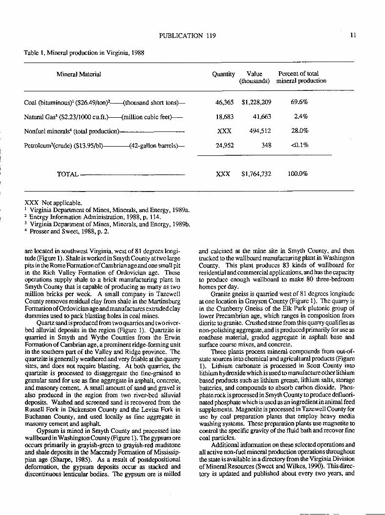
The minerals industry of Virginia has been dominated bycoal production throughout the 20th century. In 1988, thetotal value of mineral production in Virginia was almost 1.8billion dollars (Table 1). hoduction of non-fuel mineralresources was valued at about 495 million dollars in 1988, orapproximately 28 percent of the total. Coal, mined exclu-sively from the southwest Virginia coalfield located west of8l degrees longitude (Virginia Department of Mines, Miner-als, and Energy, 1989a) (Figure 1), was valued at more than1.2 billion dollars in 1988, or almost 70 percent of the total.Natural gas, which is alsoproducedexclusively from wells insouthwest Virginia, west of 81 degrees longitude (VirginiaDepartmentof Mines, Minerals, andEnergy, 1989b) (Figurel), was valued at almost 42 million dollars, or a little morethan 2 percent of the total. Collectively, coal and natural gasproduced in southwest Virginia accounted for atnlu/" 72percent of the total value of mineral production in 1988(Table 1).
Although southwest Virginia is most commonly knownfor abundant coal and natural gas resouces, the region also
has a wide variety of non-fuel mineral resources and supportsa relatively strong and stable non-fuel mineral industry. Theregion utilizes abundant carbonate and quartzite resources tosupply construction materials !o local malkets, and takes
advantage of unique geologic resoruces and manufacturingtechnology to supply specialty products used locally andshipped throughout the eastern and southern states.
NON-FUEL n/trNERAL PRODUCERS
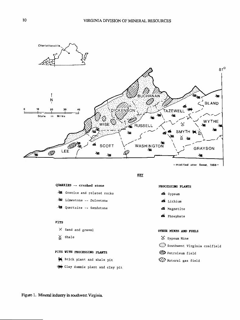
Twenty quarries produce limestone or dolostone insouthwest Virginia, west of 81 degrees longitude (Figure 1),
from the abundant carbonate resources found in the Valleyand Ridge physiographic province. Production is from sev-eral geologic formations including the Honaker Formation,Maryville-Rutledge Limestones, and Conococheague For-mation of Cambrian age; Stonehenge Limestone, MosheimLimestone, Lenoir Limestone, Effna Limestone, RockdellLimestone, Benbolt Limeslone, Hurricane Bridge Lime-stone, Woodway Limestone, and undivided limestone bedsof Ordovician age; Hancock Limestone of Silurian age; andGreenbrier Limestone of Mississip'pian age. Most quarryoperations throughout the region produce a wide variety ofcrushed stone forroad building and general construction. Themost common uses of the limestone and dolostone aggregateinclude roadbase material for public and private coal mineroads, and graded aggegate used in asphalt and concrete.Other uses include railroad ballast, septic-tank drainfieldrock, and rip-rap for reclamation of mined land and erosioncontrol.
In addition to construction aggregate, specialty lime-stone and dolostone products are produced throughout theregion. Dolostone and dolomitic limestone are produced inRussell County for use in soil treatment products, fertilizerfillers, animal feed supplements, roofing materials, structuralconcrete products, and architectural block. Chemical grade
dolostone is produced in Russell County for use in industrialfillers and glass manufacture. Quarries in Russell and Tazew-ell Counties produce mine safety dust, which is pulverizedlimestone or dolostone (at least 70 percent passing throughthe 200-mesh sieve) with low silica content (ess than 4percent free and combined silica) used in underground coalmines !o help prevent explosions from airbome coal dust.Gypsum supplied from outside of the region and locallyquarried dolomitic limestone are finely ground and pelletizedin Russell County to provide agricultural, lawn and garden
soil fieaunentproducts that dissolve quickly and are virtuallydust free. Agricultural limestone ('ag-lime") is produced inBland, Lee, Russell, Tazewell, Washington, and Wise Coun-ties.
Three shale pits, one clay pit, and two processing plants
10
0102030{0
Scale in Miles
VIRGIMA DIVISION OF MINERAL RESOT}RCES
KET
g10
IN
I
- modif ied Sweet,1988-
qIIARRISS -- crushed stone
& cranite and related rocks
& linestone -- Dolostone
& quartzite -- Sandstone
PITS
X Sand and gravel
X shate
PITS YITE PROCBSSITIG PIAI{TS
I rrict plant and shale pit
Qf c:.ay dugmie plant and clay
PROCESSIre PIATTS
d cypsum
d Lithiun
d Magnetite
d phosphate
OTEB {I!$jSS AITD FTIELS
X eyps,rn ltine
@ South*"st Virginia coalfield
@ Petroleum field
N natural gas field
Figure 1. Mineral industry in southwest Virginia.
pir
PUBLICATION 119 l1
Table 1. Mineral production in Virginia, 1988
Mineral ldaterial Quantity Value Percent of total(thousands) mineralproduction
Coal (bituminous)r ($26.49lton)2--{thousand short tons)-
Natwal G ast ($2.231 1 000 cu.ft.)--{million cubic feet) - --
Nonfuel mineral$ (total production#
Petroleum3(crude) ($13.95/bl)-(42-galton barrels)-
TOTAL
46,365 $1,228,209
18,683 41,663
xxx 494,512
24952 348
69.6Vo
2.4Vo
28.0Vo
<O.l9o
xxx $r,7&,732 l00.0%o
XXX Not applicable.I Virginia Department of Mines, Minerals, and Energy, 1989a.2 Energy Information Adminisration, 1988, p. 114.3 Virginia Depafrment of Mines, Minerals, and Energy, 1989b.a Prosser and Sweet, 1988, p. 2.
are located in southwest Virginia, west of 81 degrees longi-tude @gure 1). Shale is worked in Smyth County at two largepits in the Rome Formation of Cambrian age and one small pitin the Rich Valley Formation of Ordovician age. Theseoperations supply shale to a brick manufacturing plant inSmyth County that is capable of producing as many as twomillion bricks per week. A small company in TazewellCounty removes residual clay from shale in the MartinsburgFormation of Ordovician age and manufactues extruded claydummies used to pack blasting holes in coal mines.
Quartz sand is produced from two quarries and two river-bed alluvial deposits in the region (Figure 1). Quaruite isquarried in Smyth and Wythe Counties from the ErwinFormation of Cambrian age, a prominent ridge-forming unitin the southern part of the Valley and Ridge province. Thequartzite is generally weathered and very friable at the quarrysites, and does not require blasting. At both quarries, thequailzite is processed to disaggregat€ the fine-grained togranular sand for use as fine aggegate in asphalt, concrete,and masonry cement. A small amount of sand and gravel isalso produced in the region from two river-bed alluvialdeposits. Washed and screened sand is recovered from theRussell Fork in Dickenson County and the Irvisa Fork inBuchanan County, and used locally as fine aggegate inmasonry cement and asphalt.
Gypsum is mined in Smyth County and processed intowallboard inWashington County (Figure 1). The gypsum oreoccurs primarily in grayish-green to grayish-red mudstoneand shale deposits in the l4accrady Formation of Mississip-pian age (Sharpe, 1985). As a result of postdepositionaldeformation, ttre gypsum deposits occur as stacked anddiscontinuous lenticular bodies. The gypsum ore is milled
and calcined at the mine site in Smyth County, and thentrucked o the wallboard manufacturingplant in WashingtonCounty. This plant produces 83 kinds of wallboard forresidential andcommercial applications, and has the capacityto produce enough wallboard to make 80 three-bedroomhomes per day.
Granite gneiss is quanied west of 81 degrees longitudeat one location in Grayson County @igwe 1). The quarry isin the Cranberry Gneiss of the Elk Park plutonic group oflower Precambrian age, which ranges in composition fromdiorite to granite. Crushed stone from this quarry qualifies as
non-polishing aggregate, and is produced primarily for use as
roadbase material, graded agE.egate in asphalt base andsurface course mixes, and concrete.
Three plants process mineral compounds from out-of-s[ate sources into chemical and agricultural products (Figwe1). Lithium carbonate is processed in Scott County intolithium hydroxide which is used to manufacture other lithiumbased products such as lithium Br@se, lithium salts, storagebatteries, and compounds to absorb carbon dioxide. Phos-phate rock is processed in Smyth County to produce defluori-natedphosphate which is usedas an ingredientin animalfeedsupplements. Magnetite is processed in Tazewell County foruse by coal preparation plants that employ heavy mediawashing systems. Thesepreparation plants use magnetite tocontrol the specific gravity of the fluid bath andrecover finecoal particles.
Additional information on these selected operations andall active non-fuel mineral production operations throughoutthe state is available in a directory from the Virginia Divisionof MineralResources (Sweet andWilkes, 1990). Thisdirec-tory is updated and published abut every two years, and
t2 VIRGIMA DIVISION OF MINERAL RESOURCES
includes company names, address, telephone number, min-eral commodities produced, geologic data on the source rockworked, and location map for mue than 300 operations.
SI.JMMARY
Southwest Virginia west of 81 degrees longitude sup-ports a relatively snong and stable non-fuels minerals indus-try that produces construction aggregate, industrial minerals,agricultural products, and specialty mineral products. Mostconstruction aggregate, which includes crushed limestone,dolostone and quartzite, is used in local markets. Someproducts, such as gypsum wallboard, dolostone and lime-stone agricultural products, chemical grade dolostone, andface brick, take advanlage of geologic resources that areunique to the region and are marketed throughout the easternand southeastern states. Other products, such as mine safetydust, rip-rap used in reclamation of mined land, struchralconcrete products, manufactured clay dummies, and proc-essed magnetite, are also unique to the region and producedto supply markets directly created by the coal mining indus-try.
REFERENCES CITED
Energy Information Administration, 1988, Coal Production1988: Office of Coal, Nuclear, Electric and Alternate Fuels,U.S. Department of Energy, DOE/EIA4l18(88), 144 p.
Prosser, L. J., Jr., and Sweet, P. C., 1988, The MineralIndustry of Virginia: U. S. Bureau of Mines Mineral Year-book 1988,8 p.
Sharpe, R. D., 1985, Geology and Mining of Gypsum inVirginia, in Glaser, J. D., and Edwards, J., eds., TwentiethForum on the Geology of Indusrial Minerals, IndustrialMinerals of the Mid-Atlantic States: Maryland GeologicalSurvey, Deparrnent of Natural Resources, Special Publica-tion No. 2,p.4149.
Sweet, P. C., and Wilkes, G. P., 1990, Directory of theMineral Industry in Virginia - 1990: Virginia Division ofMineral Resources, 36 p., 1 map.
Virginia Department of Mines, Minerals, andEnergy, 1989a,1980 to 1988 coal production records: Unpublished data onfile with the Division of Mines, Big Sone Gap, Virginia.
Virginia DeparUnent of Mines, Minerals, and Energy, 1989b,1988 Summary of Oil and Gas Activity in Virginia: Unpub,lished annual reportpreparedby the Division of Gas and Oil,Abingdon, Virginia
Vulcan Materials Company was granted a rezoningclassification and special use permit for a new quarry inStafford County, Virginia on December 19, 1989. The voteof approval came after several minutes of discussion duringthe meeting; however, the road to this point involved hun-dreds of manhours of work and careful planning. The amountof work done towards each individual zoning or site permit-ting plays an important role in each case, but more impor-tantly, the company's history of operational responsibilityplays a major part in this process. In today's climate ofcontrolling urbanization and growth, the day of the inespon-sible and unconcerned mine operator are gone. The operatorwho thinks that he can ignore blasting, dust or truck problemswill soon be payrng a visit to the unemployment line, muchless getting new operations opened.
Only when acompany is confidentaboutits operationalresponsibility, public image and its efforts to become an"About Face" company, should it attempt a rezoning-permit-ting situation. The average zoning or permitting procedureoflen costs hundreds of thousands of dollars; therefore, thecompany's operating history and environmental stewardshipcommitment and concern has to be in order or the amount ofmoney invested in a rezoning situation will be of no conse-quence.
The area to be chosen for an expansion (greenfield site)shouldbe in an areaofpresent orfuture marketpotential. Thismarketphenomenon is what makes ttre location of permittingso difficult. In order to have a thriving, bustling market, alocation must have active housing, road building and agrowing economy in order to create the need for a generallylow-cost product wittr a high nansportation cost. This neces-sitates that the quarry site be close to growth areas; however,the growttr areas are the most controversial places for aquarry. Producers could get an operation zoned fifty milesfrom town; the only problem is that the product may not sellif you can't be the low cost supplier to the market.
Once apotential marketis located, thereal workbegins.A high quality deposit must be located and ample reservesproven for future growth. The mineralogy of the depositmustbe evaluated completely and concerns about environmentalmatters must b anticipated from neighbors and citizens. Adeposit needs to be located with sufficient buffer land, agree-able landowners, good transportation access and in a fairlyremote area thatprotects neighbors environmentally. Lack ofany of the abovecould spell defeat for apermitting proposal.
The next step is to acquire or lease the land involved.Once this is done, a zoning attorney needs to be brought online along with necessary consultants to present specific areasof expertise. Often mining companies attempt to do this "InHouse;" however, their credibility is diminished in that they
PUBLICATION 119 13
REZONING AND PERMITTINGQUARRY SITES
Alexander S. Glover, Jr.Vulcan Materials Company
MideastDivisionP. O. Box 1590
Manassas, Virginia 221 10
are perceived as the "biased applicant." Independent firmswhich generally are known as the tops in their field shouldpresent the facts and information in report form to thepermitting body. Much of this information must be sitespecific o the new operation. Every application will involvethe same controversial factors which include: Hydrology,Property Values, Blasting, Transportation, Trucking, Geol-ogy, Dust, Environmental, Archaeological and Engineering.You must anticipate that all of these subjects will be broughtup. The applicant should be prepared with facts to demon-strate that these factors are not adverse to the area.
Homework completed, the applicant will most likelyface emotionally concerned adjoining neighbon at a publichearing. Many of these people will be loaded with miscon-ceptions and fears about the mining industry. These fearsshould be addressed at the beginning of the meeting. Thismeeting is also where "skeletons in the closet" of an opera-tions past can kill the application. A producer, applying fora permit, who has consistently ignored neighbors and good
operating practices, will be shouted out of the room uponstating that he will comply with all regulations for his pro-posed sites. What is this producer to do? He cannot go backand change what has gone on in the past. The answer,therefore, is that he must begin a responsible mode of opera-tion today and return with a proposal in five to ten years. Onthe other hand, the responsible producer will have adjoiningneighbors of existing operations testify to the permittingbody, favorable experiences with the operator. The industrycannot place a value on favorable statements that are theresult of well managed, concerned operators. Once thepermitting body hears these comments from neighbors toexisting operations, thepolitical decision thatthey will makeon a proposed similar operation in their disrict will be morefavorable.
In conclusion, an existing expansion (greenfield site)proposal mustbe in therightplace - at therighttime, with theright conditions, and have sister operations which have con-sistently operated in a responsible manner in the past; afterall, is it not often said "One's furure is judged by his pasL"

t4 VIRGIMA DIVISION OF MINERAL RESOURCES
PUBLICATION 119
EVERY LAW CREATES AN OUTLAW{'
15
Bobby J. TimmonsTimmons Associates
P.O.Box 50606Jacksonville B each, Floida 32240
ABSTRACT
Adversarial relationships, between the Regulator and the Regulated, are expanding daily and resulting in prejudicial deci-
sions instead of practical onis. One upmanship has gone beyond romance, politics, sports and ttre stage into an area where reason
should be paramount, and is necessary for the continuation of our way of life.This paper will discuss the rhetoric, response/retaliation and lack of re?^soning affecting the industrial minerals mining
industry. T'o^ttreOegreepossible,itwillbeabipartisanpresentationreflectiveof theauthor'sexperienceinbotharenas. Suggested
modus operanOi w'iU be offered to promote cooperation in lieu of confrontation and therefore, with consequent benefits to
everyone.
The purpose of this presentation is not to critique existingmining laws but rather !o appeal for a fair and cooperativeenforcement of those laws. Early mining laws and for themost part, Federal, beginning with the Mining Law of 1872,were primarily concemed with land or mineral lease acquisi-tion and maintenance of possession. Today, clear title does
not necessarily guamntee the right of development due to the
advent of hundreds of thousands of laws by various entities.Frustration and conftadiction stemming from minerals
regulatory authorities is not Johnny-come-lately. @ease beaware of the distinction between the 'tegulations" and the"regulators".) Profits were allowable to Roman individualsforthe useof aproperty under theJustinian Codeof theSixthCentury. Under this usuftuct system, stat€ mines wereoperated as long as no damage was done to the property butthe opening of new mines on the property was a violation ofthe uSufuicl. Pliny the Elder indicated in his writings that heItalians considered mining as a land abuse to be discouagedin the Motherland but permissible in conquered lands. These
are ancient laws but with modern day rings of familiarity tomost of us.
To set, to the degree possible, the bipartisan tone of thispresentation, be reminded that the previous paragraph istaken almost verbatim from a planned presentation entitled,"Both Sides of the Coin." Byron Cooper (1966) further set
the stage at the First Midwest Forum in this bipartisandiscussion:
"...Some of the government experts took positions thatwere on occasion ludicrous and indefensible. Geologist "X"deprecatedthe opinions of allexperts who did notagree withhim, and alsorejected many authoritativepublications of thegovernment by saying all were "unEustworthy," whereuponhe interposed his own definitions and added "I am moredefinite about it than most people who work with the field""
* "Title borrowed from and used with the full permission ofMaxine Stewart,I{azen Research, Golden Colorado - from anewsleser article wiuen by ItIs. Stewarl'
"In theErie Stone Company case, Geologist"Y" identi-fied as "sloppy" those definitions of limestone that did notagree with his own, and said he felt very poorly toward somegeologists because of their sloppy definitions. Geologist'Z"appeared as a govemment witness in the James River HydrateCompany's case and argued that dolomites were not classed
with limestone by most geologists. I think these gentlemen
missed ttre main point ttrat was before the courts; ttreirindividual opinions were irrelevant." The quoting of Mr.Cooper here is to emphasize that regulatorS do not hold thepatent on ludicrousness.
We have allbroken laws! If there is onepe,rson herewhohas not, I will end this presentation now. Okay, we have nowestablished the common tlread of criminality, henceforth we
will discuss degrees of guilt. Now ttrat the sanctimonioushave been brought o their knees, I would like to lay a guilt tripon everyone, and particularly on the regulators brave enough
!o be in the audience. Please remember that yQ!, all of you,
are consuming, and I will be so bold as to state an equal
amount, of mined products as the rest of us. Therefore, Iwould like for you to consider yourself apart of any problems
allegedly caused by mining rather than an extra-terrestrialbeing without extractive mineral indusry sins.
My aim here today could perhaps best be accomplishedby asking ttrat all attendees and others who may review the
Proceedings, would reread the many presentations with asimilar purpose given at a number of previous forums. Manyof those specific presentations are quoted and/or listed as
references for this paper. I have excerpted freely, with proper
credit and sincere appreciation.A sampling follows: Ian Campbell (1967) said at the
ThirdForum, "The future of theindusrial minerals is indeed
bright and the touchstones for assuring and further brighten-ing that future lie in research, (researcI in exploration'mining, beneficiation, transportation and applications), ininnovative thinking and planning, and - most important ofall- in social and political cooperation."
I-anceMeade (1969) asked therhetorical question attheFifth Forum, "How can an industry which has been the
16 VIRGINIA DIVISION OF MINERAL RESOURCES
supplier of the raw materials tlat have enabled our presentday technically advanced society to develop, allow iself to befaced with possible extinction by this same society?',
To aid in your search for humility, I hope, read LarryRooney's (1970) Keynote Address from the proceedings ofthe Sixth Forum - held in Michigan.
To show that the ag$egates industry is and has beenaware of problems/solutions, critique William E. Hole, Jr.'spresentation, "Environmental Problems and the ConstructionAggregates Industry," also presented at the Sixth Forum.
Peter T. Flawn (1972) said: "It seems clear that withoutan enlightened national mineral policy that defines the inter-ests and objectives of the nation and sets out specific actionsrequired to accomplish those objectives, United States' in-dusfy will face potentially destructive supply problems inobtaining raw materials, including mineral fuels, and poten-tially destructive economic problems in maintaining opera-tions. Indeed, the economic impact will extend far beyond themineral industry. The solution to the anticipated problemslies in the public policy area."
Jim Dunn (1982) asked the question: "How can we solvethe basic riddle of resource management in the broad publicinterest? The changes needed are educational, mental andIegal." I would add, and without a thought of correction ofMr. Dunn, an education for the legal profession.
I perceive as a basic problem in the "laVoutlaw" di-lemma, that we have too many lawyers acting as pseudogeologists, hydrologists, engineers and certainly, aspoliti-cians. Perhaps the reverse is true as well for I fi nd that inireas-ingly I'm asked an opinion as to what some rule or regulationm-eans or how some agency is likely to respond. The epitomeof this dilemma is the familiar, "What was the intent?"
We, as geologists, must bear our fair share of tre res-ponsibility for this dilemma. For too long; and would that itcould continue, we have been content, maybe even pom-pously so, to be closet scientists and leave the politicking tosomeone else. The plethora of laws written to thwart orbenefit developers but which affect, and normally adversely
19, !!-te mining industry, are well known to most of you.Similarly, there are blanket laws written, and often pas'seO,rggarding "Mining operations will, musl.. etc.," when theyshould read so as to apply to a certain commodity at worst, andin a certain geologic province. As dislasteful as it may be,you,{ need to be sure that legislatorsftegulators know whereofthey speak.
the contrary, some laws have favored mining asindicated by Wally Fields (1971) at the Sevenrh Forum,l'...from ttre beginning of time until 1967, the only Floridalaws directly governing mining operations were the threesimple little laws..."
"In 1891, Sec. 768.10F.S. was adopted. This law made
1t unlaivful for any person to leave a pit or hole open whichhad a depth orbreadth of more than two feet, unless the samewas enclosed by a fence to prevent horses, cattle or otherdomestic animals from falling into the same. The actgoes onto say, however, that ttre law shall not apply to personsengaged in mining operations so long as those operationscontinue."
The following statement has been used on several occa-sions and to those of you who may have heard it, I apologize
for repeating it. However, Professor R.A.L. Black's state-ment, "Society should be reminded that nearly g!! the ameni-ties of modern life which it takes for granted are products ofthe minerals industry and the engineers and others who serveit" is as true today as almost 12 years ago when I first quotedhim (Timmons, 1978). W. L. Dare, a Wilderness and RiverBasin Coordinator for the U.S. Bureau of Mines recognizedthis paradox in saying, "...while affluence has motivated oursupporttopreserve the quality ofthe natural environment, in-dusfial development is needed to support the affluence."
To you here who may be regulators, now the fourthbranch of govemment, with EPA a cabinet level agency, Irecommend as required reading, "Industrial Minerals, CanWe Live Without Them?", by Hal McVey from the April,1989 issue of Industrial Minerals. To the pure and puritangeologists in attendance, I suggest reading and practicing thecomments by Karl W. Mote in the March, 1990 issue ofGeotimes.
My contention of several years ago that the RegulatoryBranch was now the fourth branch of government is sup-ported by this Rock Products statement:
"As early as 1952, Supreme Court Justice Robert H.Jackson warned: 'The rise of administrative bodies probablyhas been the most significant legal trend of the last centuryand perhaps more values today are affected by their decisionsthan by those of all the courts. They have become a veritablefourth branch of the government, which has deranged ourthree-branch legal theories as much as the concept of a fourthdimension unsettles our three dimensional rhinking (Tim-mons, 1978)."'
Most adversarial relationships are fostered by egotisticalmaniacs,pompous donkeys, orin thecaseof the extractivein-dustry, overzealous regulators or stubborn industry person-nel. Quite often, the players are similar to reformed smokers,former drug abusers or alcoholics and please, I mean nodisrespect whatsoever. The point is their reformed halosrestrict their ability for clear, objective reasoning. Remem-ber, a halo has but to slip a liEle to become a noose. However,an appreciation borne ofexperience on both sides ofthe coin,may be tle only fair and effective way legislationfegulationcan be designed. To reiterate,renlize you are also part of theproblem, even more so than a part of the solution.
The MMBY syndrome has become so commonplacethat the acronym itself needs no explanation. The extent towhich this syndrome is active is virtually all inclusive. n&,and notice the inclusive pronoun, under the MMBY syn-drome, object to rock quarries, rock concerts, rock haultrucks, rock dusl..everything with a rock description exceptwhen it applies to a diamond. We also object to shoppingcenters, landfi lls, airports, highways, offi ce buildings, manu-facturers, chemical plants, light noise, vibration, dirty air,dirty water, dirty language, insurance costs, high medicalbills, gas prices, ad infinitum. Name me one of thoseobjections to which any of you can say you do notconribute.
A NIMBY story and in ggy backyard - The City ofJacksonville - needs a new landfill site desperately. Ifyouconsider our geographic position, and would hazard (no punintended) an educated guess at the geology, you realize theinherent problems; a high water table wirh a highly permeableand comparatively thin sand covering, overlying the Florid-
PUBLICATION IT9 17
ian Aquifer, the source of most of our water supply. From allindications, the solution to this site search hasbeen to beginwith the legal aspects and add in, Uaybg, the geology as anafterthought. Partof the legal evaluation has been to have the"City's lawyer walk over the property at $175.00/hour."(This fee was recently raised to $ 190.00lhour, but public dis-closure and subsequent outcry caused it o become "a mis-take.') To this counry boy, approach the problem in the sameorder as occurence; geology first and the lawyerssubsequently, g@ physical suitability has been determined.
The proposed Jacksonville landfrll is complicated by thefact that the proposed site is located adjacent to the St. JohnsCounty line, in the extreme southeastern corner of DuvalCounty-Jacksonville. Need I further tell you that Sr Au-gustine, reputedly the oldest permanent settlement in NorthAmerica, is in St Johns County. Jacksonville's ldayor,presumably, according to the local newspaper, filed a suit tocompel the existing landfill site in St. Johns County (servingSt. Augustine) to conform to the same regulations as theproposed site to serve Jacksonville. Adversarial relation-ships? You be the judge!
At a city council meeting in Tallahassee a few years ago,a council member proposed that all bonow areas, mined pits,etc., be filled back to original grade. This seemed like a goodidea until the State Geologist, who luckily was in attendance,pointed out that in order to do that, other holes would have tobe dug. Sounds like a good military exercise, eh? Be carefullest your laws create outlaws or more problems than theysolve.
On March 12 of ttris year, a quarry operator in theNorttreast (no state names by choice, notby request) told meof a runoff water controversy at one of his operations. Aseries of settling ponds were utilized to clarify process waterfor recycling, with releases from the clarified pond onlyduring periods of heavy rainfall and plant inactivity. Toinsure that no turbid water would leave the site, he designeda collection system for casual water also to flow into hissettling ponds to fully clarify that water. DEP said "no",because that now becomes process water. So, he is nowdesnoying the casual water collecting system and allowing itto flow directly into ttre natural system, turbidity norwithstanding. Practical, prejudicial, by the book,whatever...another outlaw created, government mandatedand supported.
Unfortunately, another paradox exists which strikes atthe very roots of what this country has stood for throughoutthe centuries. A little story about Francesca Monjiardo ofWhitesburg, Kentucky as an illustration: Francesca came 0o
this country from S an Andrea through Ellis Island in I 902 andbecame part of the sizable Italian community in Whitesburg(Caudill, 1980). Because of pronunciation difficulties andother reasons, he became Americanized as Frank Majorityand tle name became commonplace to him. The conditionsof immigration for many in the Italian community were quitesimilar to the Mariel Boatlift, but Frank Majority sEove,almost too hard, to be an exemplary citizen. As such, duringWWII, he dug coal for himself and a couple of his neighborsfrom a thin seam which outcropped next to his house. Toolsof recovery were a mattock and shovel, pick and wheelbar-row. The S.F.A., Solid Fuels Administation, having decreed
that nearly all coal should be used in the war effort, notifiedeveryone by post office poster that any "person, firm orcorporation engaged directly or indirectly in the productionof coal"...must register with the S.F.A., receive a code num'ber, have his ouput allocated andprice fixed. Failure to do
so could mean a'$ I 0,000.00 fine, ten yean imprisonment orboth." Frank Majority was inundated with mail; wanting oknow whatvein he was mining andits prox analysis, numberof employeas, amount of elecricity he was consuming,number of rubber-tired vehicles (I don't know if the wheel-barrow qualified) and diesel or gas powered, wages per hour,day and week, tons produced daily, names and addresse's ofall customers and price charged per ton, probable productionfor each month of the coming year and that he could charge
$3.85 perton andmustship to the "designated warindustry."Frank abandoned thelittle coalpitand the stoveran short,butthe torrent of mail continued. One day Frank gave up andquit. He said, "I just serva tlp time, but I no answer thequestions. Ten years onna rock pile is better thanna ten years
answer the questions!" The entrepreneur, the small business-man, the backbone of this country, forced (literally) out ofbusiness. I wonder if Frank became one of those facelessfigures in the commodity lines of Eastern Kentucky? Con-sider the total consequences of your actions!
Two ridiculous stories, from opposite sides of the coin,and these are but two of thousands, no doubL R. Lee Astonin the December, 1989 issue of Pit & Quarry, states:
. "In an unusual case, Town ofNorth }lampton vs. Sander-son, a sand and gravel producer in New Hampshire tried !ooperate without permits by spoofing the courts into believinghe was actually a home builder.
Although the producer operated a 14-acrc gravel pit in aresidential subdivision for more than eight years, he claimedhis main purpose was to prepare building sites.
The producer said he was merely trying to lower the
elevation of the lots o that of the road. Since he was not'offrcially' a mining operation, he claimed he was not re-quired to obtrin mining permits from the state or use permitsfrom the town zoning board."
Having had very recent experience in the area, I canvouch for numerous similar permits issued to prepare resi-dential lots. Equally questionable are the permits issued for"digging a lake" in Dade County, Florida. Childish, yes, butI have often statedrhat if you persist in childish treatment, youwill eventually evokeftrovoke childish responses.
And now the other side - a Citizens Advisory Group tothe St. Johns Water Management Disrict in Florida recentlyexperienced a unique attempt at regulatory enforcement.Brmklyn Lake, north of Keystone Heighs, has been dryingup as have many sinkhole type lakes in Florida, due to thecontinuing drought (Guerry McClellen, 1990, personal
communications). Their (the Advisory Group) concern andsubsequent efforts resulted in obtaining a work force from theLawtey Conectional Institute to clean out an inflow dirch inhopes of raising the water level. A member of the Sr JohnsWater Management District Board told the group no permitwould be needed for such activities. While performing the"clean-out" chores, tle convicts were leveling or smoothingthe bottom and sides of the ditch. A cruising DER memberquestioned the activity without a permit and threatened to
18 VIRGIMA DIVISION OF MINERAL RESOURCES
arest everyone. This overzealous regulator was informed ofwhat a neat trick this would be inasmuch as all currently wereassigned numbers, cells, etc. Newspapers had a fieldday.
Solutions, I can only suggest.To the regulators, be as informed as possible to the total
consequences of your effors and as educated as possibleaboutthe entityygg ggenfusted toregulate. your subjectivetasks mustbe approached with as much objectivity as you canmuster. Be reminded that complete objectiviry is possibleonly with machines...and they are being influenced by theprogrammer.
The miners/geologists must be active in the politicaVpublic policy arena. Become involved before the crisis stageandbefore adversarialrelationshipsbegin to form. Ourworldis too confined fon our activities as either law-makers or law-breakers, as maybe I have suggested, not !o affect fellowhuman beings. So, approach your tasks with a purpose ofcooperation, not confrontation.
REFERENCES CITED
Campbell,Ian, 1967, The Industrial Minerals: In Retrospect,Introspect and in Prospect Special Disribution publication34, State Geological Survey of Kansas, A symposium onIndusrial Mineral Exploration and Development, proceed-ings of the Third Forum on Geology of Industrial Minerals,p.6.
Caudill, Ilarry, 1980, The Mounlain, The Miner and TheLord: The University hess of Kentucky, p. I0g-121.
Cooper, B. N., 1966, Limestone and Dolomite: Geologistsand Percentage Depletion Allowances: The Ohio Journal ofScience, Vol.66, No.2, p. 148, A symposium on Geology ofIndusrial Limestone and Dolomite.
Dunn, J. R., 1982, Dispersed Benefit Riddle, (Keynote Ad-dress), Proceedings of the Eighteenth Forum on Geology ofIndusrial Minerals, Indiana Geological Survey OccasionalPapr37,p.6.
Fields, D. W., 1971, Mineral Resource laws: The Specre ofEcology: Special Publication No. 17, Florida Bureau ofGeology, Proceedings of Seventh Forum on Geology ofIndustial Minerals, p. 7.
Flawn, P. T., l97Z,Impctof Environmental Concerns on theMineral Industry, 1975-2000: Symposium on tlre MineralPosition of the United Srar€s 1975-2000, Society of Eco-nomic Geologists, p.6.
McClellan, Guerry, 1990, Penonal Communication in refer-ence to the Brmklyn Lake comments.
Meade,I-ance, 1969, Industrial Minerals and the Community- An Alienation Gap (Absract), Mineral Resources ReportM64, Bureau of Topographic and Geologic Survey of Penn-sylvania, Proceedings Fifth Forum on Geology IndusrialMineral, p.225.
Rooney, L.F.,1970, The Party's Over: A Rambling Dis-course on Suspended Contempt, The Bittersweet Boom andOther Heresies, Proceedings Sixth Forum on Geology ofIndustrial Minerals, p.2 - 3.
Timmons, B. J., 1978, Minerals Depletion by Legislation,Regulation and Procrastination, Presentation fo the SertomaClub of Orange Park, Florida.
COMPUTER APPLICATION
ABSTRACT
The process of determining the finished land form of asand and gravel operation, before mining begins, involves thesystematic integration of a variety of data. This informationconsists of local land use policies, environmencal regulations,reclamation standards, mining procedures, earth movingequipment, site conditions and mostimportant of all, depositcharacteristics. The quantity, quality and distribution of boththe overburden and the deposit are crucial for pre-mineplanning. Equally important is the need tn predict theultimate configuration of the mined-out deposit relative toadjacent landelevation, ground water table and contour of thedeposit floor. This paper presents a caso study of a sand andgravel pre-mine reclamation project. It illustrates the interac-tion betwern thO geologist and landscape architect and thepre-mine planning process.
Our client had data from 75 test borings that had beendrilled to evaluate a sand and gravel deposit. Surfer, acomputerprogram,required an x, y andz coordinate foreachtest hring. In addition, the program used drill logs and testdata to supply information about the overburden thickness,the depth [o water, the thickness of tlo minable sand andgravel and the amount of tle deposit that lies above and belowwater. Output from theprogram consisted of the followingmaps: a topographic map, aproperty map with a grid to showtest boring locations and isopach maps of overburden, depositthickness, and thickness above and below water. Thesegraphics illusrated the characteristics of the deposit as thekey daa for the mining and reclamation plans.
These datawere tlen analyzed to resolve threequestions.First, what areas of the deposit have the best reserves and thehighest potential for land development? Second, how can theoverburden be used most efficiently to create usable land?And third, what extraction pattern would be most beneficialto both the mining and the land development operations?
INTRODUCTION
The projectbegan with ameetingbetween theclient, thelandscape architect and tle geologist. The client owns nearly800 acres from which they expect to mine sand and gravel. Inthe interest of making maximum use of the land and re-sources, the client wanted to develop a mining and reclama-
PUBLICATION 119
FOR RESERVES ANALYSIS AND MINE PLANNING
IL Lyn BourneP.O. Box 293
Northville, Michigan 48 I 67
and
Anthony M. BauerMichigan State University
4528 Herron RoadOkemos, Michigan 48864
19
tion plan at the beginning of the program . Not only would theplan be the basis for their operation, but it would also serve as
the foundation for acquiring the necessary mining permits.The landscape architect outlined the geologic informa-
tion that would be needed to initiate their work. They needed
to know the boundaries of the deposit, the thicfrness ofoverburden, the depttr !o water, and the amount of depositabove and below water. These characteristics of the depositwere necessary for the development of a long range miningand reclamation plan.
A review of the existing drill data showed thatpars of theproperty had not been drilled and that additional drilling andtesting was necessary to complete the required information.Previous drilling consisted of 60 test borings, but sampleswere collected and tested from only l7 of those. We decidedto drill 16 additional holes to better define the boundaries ofthe deposit and to collect samples fo1 analysis to confirminformation about the 43 holes where no samples had beentaken.
The landscape architect and geologist discussed howbest to present this information and decided that a series ofcontour maps plus a table of information would provide thebest format. The goal of the information phase of the projectwas to develop this series of maps and to tabulate theinformation from the drilling and testing for the landscapearchitect Quantitative data sought to show overburdenthickness, boundaries of the deposit and total minable thick-ness (both above and below water). The qualitative dataneeded to identify the proportion of sand, gravel and clay.The amount of clay (wash loss) was important for helpingpredict volumes of material that could be available for recla-mation.
METHODS
For the 16 additional testborings a drill rig equipped wittthollow stem augers was used. Samples were collected at five-foot intervals with a two-inch diameter split spoon sampler.Standard sieve analyses were run o determine not only thequality of material that would be available but also theamount of wash loss. Wash loss data usually only givesnegative information, butin this case thevolume of wash losswas considered in the reclamation plan.
During the drilling, the thickness of overburden and
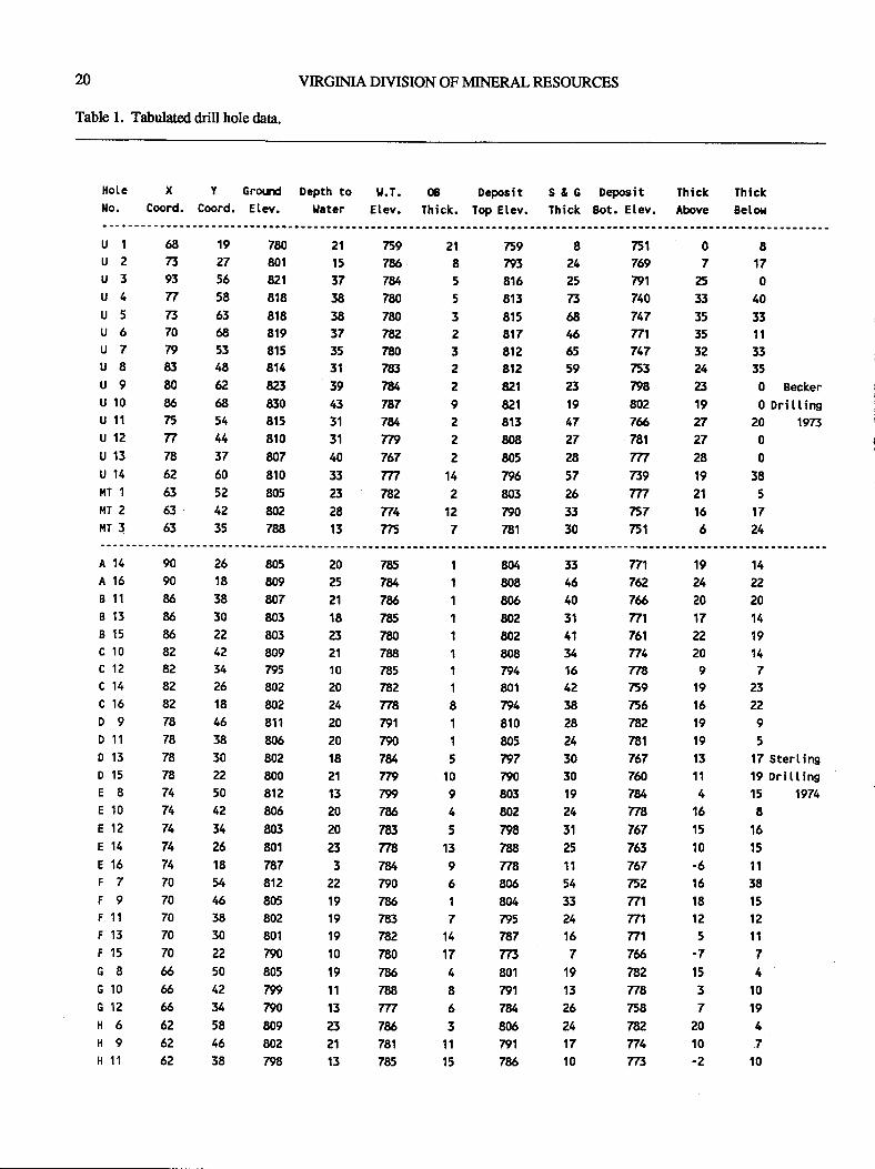
20
Table 1. Tabulated drill hole daa.
VIRGIMA DIYISION OF MINERAL RESOURCES
817
0
40
33
t1
33
35
0 Eecker
0 Drittins20 1973
0
0
38
5
17
24
Hote X Y Grorrd Depth to tf.T. OB Deposit S & G Deposit Thick Thickllo. Coord. Coord. Etev. Uater Etev. Thick. Top Etev. Thick 8ot. Etev. Above Beton
0
7
25
33
35
35
32
24
a19
27
27
28
t921
16
6
ul 68 19 780 21 E9 21 E9 8 751
u 2 T3 27 801 t5 7% I 793 24 769u 3 93 56 821 37 7U 5 816 2' 791u 4 n 58 818 38 780 5 S13 73 740u 5 73 63 818 38 780 3 8r5 68 747u 6 70 68 819 37 782 2 817 46 771u 7 79 53 815 35 78 3 812 65 747u 8 83 48 814 3t 783 2 El2 59 753u 9 80 62 823 39 784 2 821 23 W8u 10 85 68 830 43 787 9 821 19 802u 11 75 54 E15 3t 7U e 813 47 76u 12 n 44 810 3r Ttt 2 808 27 781u 13 78 37 807 40 757 2 805 28 mu 14 62 60 810 33 m ft 795 57 739l,fT 1 63 52 805 23 782 2 803 26 milT 2 63 42 802 28 774 12 790 33 E7r,fT 3 63 35 788 13 775 7 781 30 fr1
14
22
20
14
19
14
723
22
9
5
17 Sterting19 Drittinst5 1974
8
16
15
1l58
15
12
11
7
4
10
19
4
7
10
19
24
20
17
22
m9
19
16
19
19
13
1l4
16
15
10
-616
18
1Z
5
-7
t53
720
10
-2
A 14 90 26 805 20 785 I 804 33 771A 16 90 18 809 25 7U I 808 46 762B 1t 86 38 807 21 7U l 806 40 76B 15 86 30 803 18 785 t 802 3,t 7:71
B 15 86 22 803 23 780 I 802 41 761c 10 82 42 809 21 788 I 808 34 774c 1? 82 U 795 10 7E5 1 794 16 778c 14 82 26 802 20 782 I 801 42 E9c 16 82 18 802 24 Tn 8 794 38 E6D 9 78 46 811 20 791 I 810 28 782D 11 78 38 805 20 790 t 805 24 781D 13 78 30 802 18 7g 5 n7 30 767D 15 78 22 800 21 7n 10 790 30 760E 8 74 50 812 13 799 9 803 19 7eE 10 74 42 806 20 7U 4 802 24 TnE 12 74 34 803 20 783 5 n8 31 767E 14 74 26 801 23 778 13 788 25 763E16 74 18 787 3 7U 9 n8 11 767F 7 70 54 812 22 790 6 806 54 62F 9 70 46 805 19 7& I 804 33 771F 11 70 38 E02 19 763 7 795 24 T7'lF 13 70 30 801 19 782 14 787 16 771
F15 70 22 n0 10 730 17 TR 7 76c 8 & 50 805 19 7U6 4 801 19 782G 10 6 42 799 11 788 8 791 t3 Tt8c12 6 U 790 13 Tn 6 7U 25 758H 6 62 58 809 23 7% 3 806 24 78?H 9 62 46 802 21 781 11 791 17 774H 11 62 38 798 13 785 15 7% 10 773
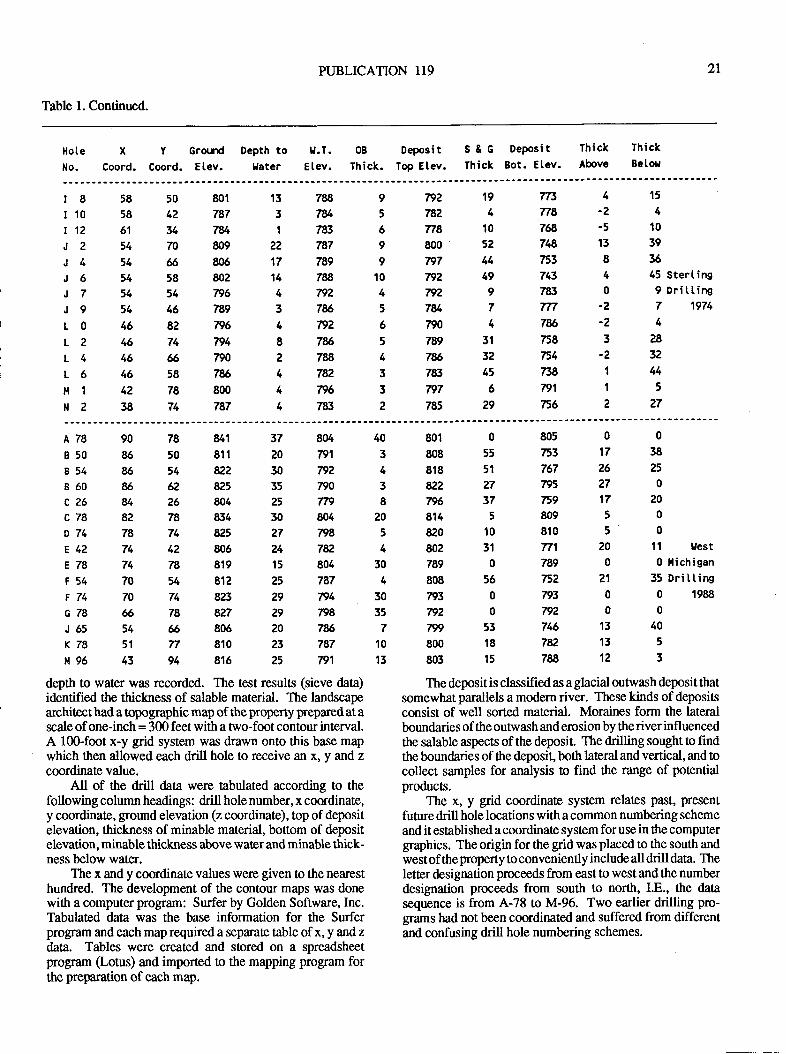
PUBLICATION 119 2l
Table l. Continued.
Hote X
No. Coord.
Y GroodCoord. Elev.
0B DepositThick. Top Etev.
S&G DePosit ThickThick Bot. Etev. Above
Depth togater
U.T.E tev.
ThickBetor
t8 58
r 10 58
t12 61
J2 54
J4 54
J6 54
J7 54
J9 54
L0 46
L2 46
L4 46
L6 46
lr1 42
N2 38
13 788
378/I 783
22 787
17 789
14 784 792
37e64nz87%27884 782
4n64 783
9 792
5 782
6n89 800
9n710 792
4 792
5784-6 7lN5 789
47865 7&3
3 797
2 785
77t 4
Tt$ -Z
78 -5
748 15
753 8
743 4
783 0
Tn -2
7U -2
758 3
754 -2
738 1
791 I75,62
15
4
10
39
56
45 Sterting9 Dritting7 1974
4
28
32
44
5
27
801
787
7U809
806
802
796
789
n6794
790
7%800
787
50
42
34
70
658
54
46
82
74
$58
78
v4
19
4
10
52
44
49
9
74
31
32
45
6
29
A78 90 78
850 86 50
8s1 86 54
860 86 62
c26 U 26
c78 82 78
D74 78 74
E42 74 42
E78 74 78
t54 70 54
F74 70 74
G78 6 78
J65 54 66
K78 51 77
lf 96 43 94
u1 37 804
811 20 791
82? 30 792
825 35 790804 25 Tl9834 30 804
825 27 W8806 24 782
819 t5 804
812 25 787
823 29 794
827 A 7%806 20 7%810 23 787
816 25 n1
40
3
4
3
8
20
5
4
30
4
30
35
7
10
13
801 0
808 55
818 51
822 27
796 37
814 5
820 l0802 31
789 0
808 56
793 0
792 0
799 53
800 18
803 15
The deposit is classified as a glacial outwash deposit thatsomewhat parallels a modem river. These kinds of deposisconsist of well sorted material. Moraines form the lateralboundaries of the outwash and erosion by the river influencedthe salable aspects of the deposit. The drilling sought to findthe boundaries of the deposit, both lateral and vertical, and tocollect samples for analysis to find the range of potentialproducts.
The x, y grid coordinate system relates p:lst, present
future drill hole locations with a common numbering scheme
and it established a coordinate system for use in the computergraphics. The origin for the grid was placed to the south andwestof theproperty to conveniently include all drill data. Theletter designation proceeds from east to west and the numberdesignation proceeds from south to north, I.8., the datasequen@ is from A-78 to M-96. Two earlier drilling pro-grams had not been coordinated and suffered from differentand confusing drill hole numbering schemes.
80500753 17 38
767 26 25
795 27 0
E9 17 20
8095081050Tl1 20 11 Llest
789 0 0 llichiganfr? Z'l 35 Dri tting793 0 0 1988
79200746 13 40
782 13 5
78a123depth to water was recorded. The test results (sieve data)identified the thiclness of salable material. The landscapearchitect had a opographic map of the property prepared at ascale of one-inch = 300 feet with a trvo-foot contour interval.A 100-foot x-y gnd system was drawn onto this base mapwhich then allowed each drill hole to receive an x, y and zcoordinate value.
All of the drill data were tabulated according to thefollowing column headings: drill holenumber, x coordinate,y coordinate, ground elevation (z coordinate), top ofdepositelevation, thickness of minable material, bottom of depositelevation, minable thickness above water and minable thick-ness below water.
The x and y coordinate values were given to the nearesthundred. The development of the contour maps was donewith a computer program: Surfer by Golden Soffware, Inc.Tabulated data was the base information for the Surferprogrcm and each map required a separate table of x, y andzdata, Tables were created and stored on a spreadsheetprogilm (Lotus) and imported to the mapping progam forthe preparation of each map.
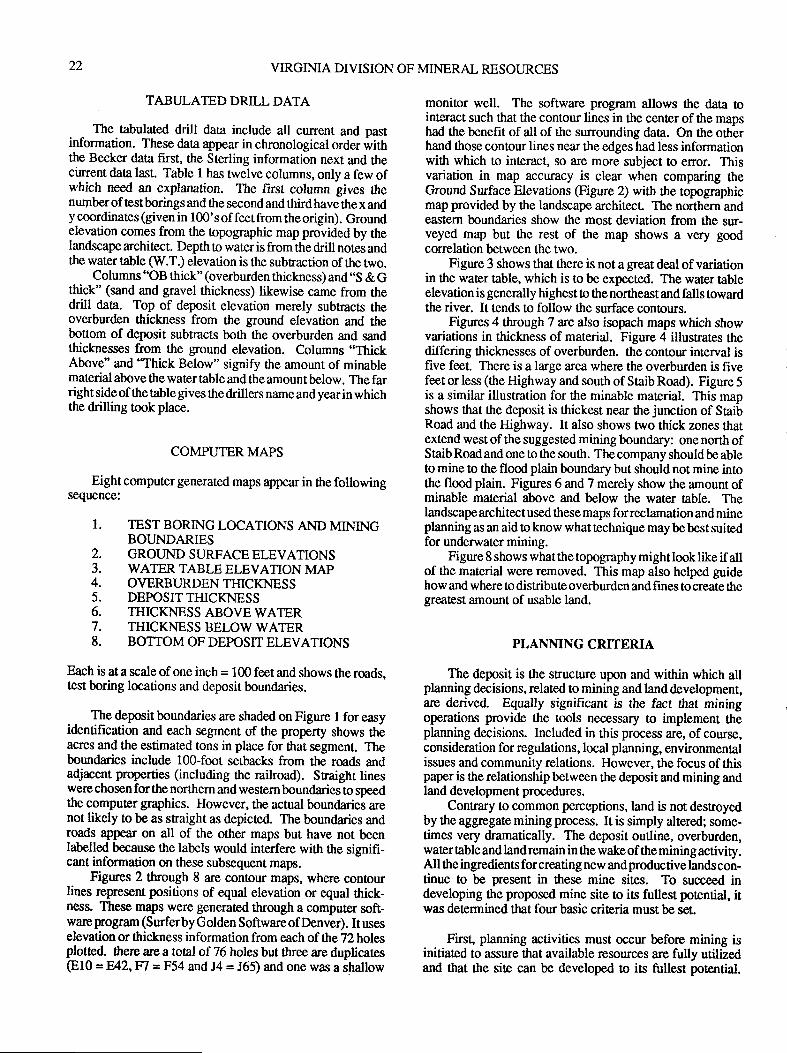
22 VIRGIMA DIVISION OF MINERAL RESOURCES
TABULATED DRILL DATA
The tabulated ddll data include all current and pastinformation. These data appear in chronological order withthe Becker data first, the Sterling information next and thecunent daa last. Table t has fwelve columns, only a few ofwhich need an explanation. The first column gives thenumhr of test borings and the second and third have the x andy coordinates (given in 100' s of feet from the origin). Groundelevation comes from the topographic map provided by thelandscape architect. Depth 0o water is from the drill notes andthe water iable (W.T.) elevation is the subfiaction of the trvo.
Columns "OB thick" (overburden thickness) and..S & Gthick" (sand and gravel thickness) likewise came from thedrill data. Top of deposit elevation merely subtracts theoverburden thickness from the ground elevation and thebotrom of deposit subtracts both the overburden and sandthicknesses from the ground elevation. Columns ..ThickAbove" and'"Thick Below" signify the amount of minablematerial ahve the water table and the amount below. The farright side of the table gives the drillers name and year in whichthe drilling took place.
COMPUTER MAPS
Eight computer generated maps appear in the followingsequence:
1. TEST BORING LOCATIONS AND MININGBOUNDARIES
2. GROT]NDSURFACEELEVATIONS3. WATER TABLEELEVATIONMAP4. OVERBURDENTHICKNESS5. DEPOSIT THICKNESS6. TI{ICKNESSABOVEWATER7. THICKNESS BELOWWATER8. BOTIOMOFDEPOSITELEVATIONS
Each is at a scale of one inch = 100 feet and shows the roads,test boring locations and deposit boundaries.
The depcitboundaries are shaded on Figure I foreasyidentification and each segment of the property shows theacres and the estimated tons in place for that segment. Theboundaries include 100-foot setbacks from the roads andadjacent properties (including rhe railroad). Straighr lineswerechosen forthe northern and westernboundaries to speedthe computer graphics. However, the actual boundaries arenot likely to be as snaight as depicted. The boundaries androads appear on all of the other maps but have not beenlabelled because the labels would interfere with the signifi-cant information on these subsequent maps.
Figures 2 through 8 are contour maps, where contourlines represent positions of equal elevation or equal thick-ness. These maps were generated through a computer soft-ware Fogmm (Surferby Golden Softwareof Denver). It useselevation or thickness information from each of the 22 holesplotted. there are a total of 76 holes but three are duplicates(810 = EAZ,V| = F54 and J4 = 165\ and one was a shallow
monitor well. The software program allows the data tointeract such that the contour lines in the cenler of the mapshad the benefit of all of the surrounding data. On the otherhand those contour lines near the edges had less informationwith which to interact, so are more subject to error. Thisvariation in map accuracy is clear when comparing theGround Surface Elevations (Figure 2) with ttre topographicmap provided by the landscape architecl The northem andeastern boundaries show the most deviation from tle sur-veyed map but the rest of the map shows a very goodcorrelation between the two.
Figure 3 shows that there is not a $eat deal of variationin the water table, which is to be expected. The water tableelevation is generally highest to the northeast and falls towardthe river. It tends to follow the surface contours.
Figures 4 through 7 are also isopach maps which showvariations in thickness of material. Figure 4 illustrates thediffering thicknesses of overburden. tle contour interval isfive feet. There is a large area where the overburden is fivefeet or less (the Highway and south of Staib Road). Figure 5is a similar illustration for the minable material. This mapshows that the deposit is thickest near the junction of StaibRoad and the Highway. It also shows two thick zones lhatextend west of the suggested mining boundary: one north ofStaib Road and one to the souttr. The company should be ableto mine to the flood plain boundary but should not mine intothe floodplain. Figwes 6 and7 merely show the amount ofminable mat€rial above and below the water table. Thelandscape architect used *rese maps for reclamation and mineplanning as an aid toknow whattechnique maybebestsuitedfor underwater mining.
Figure 8 shows what the topography might look like if allof the material were removed. This map also helped guidehow and where !o distribute overburden and fines to create thegeatest amount of usable land.
PLANMNG CRITERIA
The deposit is the sructure upon and within which allplanning decisions, related to mining and land development,are derived. Equally significant is the fact ttrat miningoperations provide the tools necessary to implement theplanning decisions. Included in this process are, of course,consideration for rcgulations, local planning, environmentalissues and communiry relations. However, the focus of thispaper is the relationship between the deposit and mining andland development procedures.
Contrary to common pe.rceptions, land is not destroyedby the aggregate mining process. It is simply altered; some-times very dramatically. The deposit outline, overburden,water tiable and land remain in the wake of the mining activity.All the ingredients for creating new and productive lands con-tinue to be present in these mine sites. To succeed indeveloping the proposed mine site to is fullest potential, itwas determined that four basic criteria must be set.
First, planning activities must occur before mining isinitiated to assure that available resources are fully utilizedand that the site can be developed to irs fullest potential.
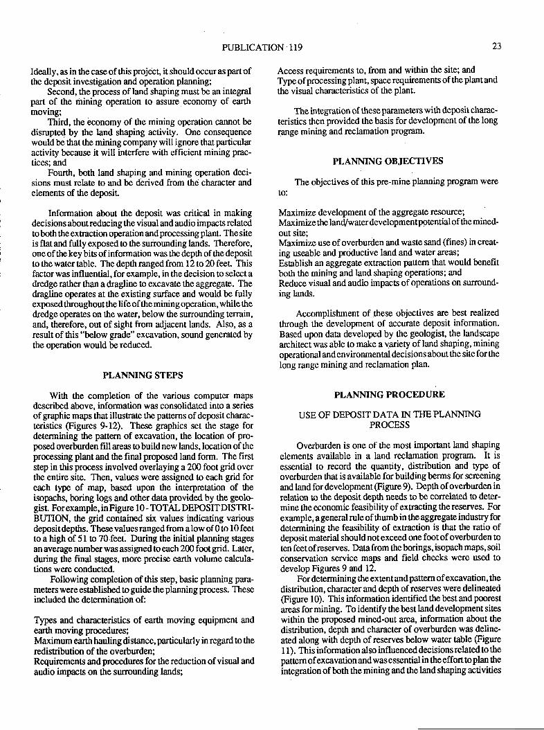
PUBLICATION 119 23
Ideally, as in the case ofthis project, it should occur as part ofthe deposit investigation and operation planning;
Second, the process of land shaping must be an integralpart of the mining operation to assure economy of earthmoving:
Third, the bconomy of the mining operation cannot bedisrupted by tle hnd shaping activity. One consequencewould be that the mining company will ignore that particularactivity because it will interfere with efficient mining prac-tices; and
Fourth, both land shaping and mining operation deci-sions must relate to and be dbrived from the character andelements of the deposit
Information about the deposit was critical in makingdecisions about reducing the visual and audio impacts relatedto both the extraction operation and processing plant. The siteis flat and fully exposed to the surrounding lands. Therefore,one of the key bits of information was tle depth of the depositto the water table. The depth ranged from 12 to 20 feer Thisfactor was influential, for example, in the decision to select adredge rather than a dragline to excavate the aggregate. Thedragline operates at the existing surface and would be fullyexposedthroughoutthe life of the mining operation, while thedredge operates on the water, below the surrounding terrain,and, therefore, out of sight from adjacent lands. Also, as aresult of this "below grade" excavation, sound generated bythe operation would be reduced.
PLANNING STEPS
With the completion of the various computer mapsdescribed above, information was consolidated into a seriesof graphic maps that illustrate the patterns of deposit charac-teristics (Figures 9-12). These graphics set the stage fordetermining the pattern of excavation, the location of pro-posed overburden fill areas to build new lands, location of theprocessing plant and ttre final proposed land form. The firststep in this process involved overlaying a 200 foot grid overthe entire site. Then, values were assigned to each grid foreach tlpe of map, based upon the interpretation of theisopachs, boring logs and other data provided by the geolo-gisL For example, in Figure 1 0 - TOTAL DEPOSIT DISTRI-BUTION, the grid contained six values indicating variousdeposit depttrs. These values ranged from a low of 0 to I 0 feetto a high of 5l o 70.feet. During the initial planning stagesan average number was assigned to each 200 foot grid. Later,during the final stages, more precise earth volume calcula-tions were conducted.
Following completion of this step, basic planning para-met€rs were established to guide the planning process. Theseincluded the determination of:
Types and characteristics of earth moving equipment andearth moving procedures;Maximum earth hauling distance, particularly in regard to theredisribution of the overburden;Requiremens and procedures for the reduction of visual andaudio impacs on the surrounding lands;
Access requirements to, from and within the site; andType ofprocessing plant, space requirements ofthe plant and
the visual characteristics of the plant.
The integration of these parameters with deposit charac-
teristics then provided the basis for development of the longrange mining and reclamation prognm.
PLANNING OBJECTIVES
The objectives of this pre-mine planning program were
to:
Maximize development of the aggregate resource;Maximize the land/water developmentpotential of the mined-out site;Maximize use of overburden and waste sand (fines) in creat-ing useable and productive land and water areas;
Establish an aggregate extraction pattem that would benefitboth the mining and land shaping operations; andReduce visual and audio impacts of operations on surround-ing lands.
Accomplishment of .these objectives are best realizedthrough the development of accurate deposit information.Based upon data developed by ttre geologist, the landscape
architect was able to make a variety of land shaping, miningoperational and environmental decisions about the site for thelong range mining and reclamation plan.
PLANMNG PROCEDURE
USE OF DEPOSITDATA IN T}IEPLANNINGPROCESS
Overburden is one of the most important land shaping
elements available in a land reclamation progam. It is
essential to record the quantity, disribution and type ofoverburden that is available for building berms for screening
and land for development (Figure 9). Depttr of overburden inrelation to the deposit depth needs to be correlated o deter-mine the economic feasibility of extracting the reserves. Forexample, a general rule of thumb in the aggegate industry fordetermining the feasibility of extraction is that the ratio ofdeposit material should not exceed one foot ofoverburden toten feet of reserves. Data from the borings, isopach maps, soilconservation service maps and field checks were used todevelop Figures 9 and 12.
For determining ihe extent and pattern of excavation, the
distribution, character and depttr of reserves were delineated(Figure 10). This information identified the best and poorest
areas for mining. To identify the best land development siteswithin the proposed mined-out area, information about the
distribution, depth and character of overburden was deline-ated along with depth of reserves below water table (Figure
1 1). This information also influenced decisionsrelated to thepattern of excavation and was essential in the effort o plan theintegration of both the mining and the land shaping activities
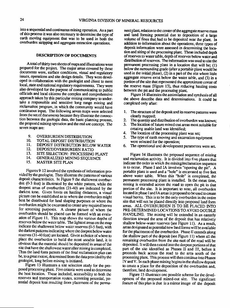
24 VIRGINIA DryISION OF MINERAL RESOURCES
into a sequential and continuous mining operation. As a partof this process it was also necessary o determine the type ofearth moving equipment 0rat was to be used in boitr theoverburden sripping and aggregate extraction operations.
nent plant, relation to the center of the aggregate reserve massand land forming potential due to deposition of a largevolume of fines that had to be deposited near the plant. Inaddition o information about the operations, three types ofdeposit information were assessed in determining the loca-tion and siting of the processing plant. These included depthof reserves to water table, depth of reserves below water anddisribution ofreserves. The information was used to site thepermanent processing plant in a location that will be; (1)below the surounding grade (after apottable plant would beused in the initial phase), (2) in a part of the site where littleaggregate reserve exist below the water table, and (3) in aportion of the site thatrepresented the approximate center oftlp reserve mass (Figure l3), thus reducing hauling costsbetween the pit and the processing plant.
Figure 14 illusraes the assimilation and synthesisof allthe above describe data and determinations. It could becornpleted only after:
l. The structure of the depositand its reserve patterns wereclearly mapped;
DESCRIPNON OF DOCTJMENTS
A total of thirty two sheets of maps and illusEations werep_repared for the projecf The major areas covered by thesedocuments were, surface conditions, visual and regulatcyissues, operations and site design deails. They were devel-oped in collaboration with the geologist and client to meetlocal, state and national regulatory requirements. Ttey werealry developed for the pupose of communicating to publicofficials and local citizens the complex and comprehensiveapprorch taken by this particular mining company to under-take a responsible and sensitive long range mining andreclamation progr:rm, in which the community would havecontinuous inpur The following seven maps were selectedfrom the setof documents because they illustrate the connec-tion between the geologic data, the basic planning process,the proposed mining operation and the end use coniepr Theseven maps are:
9. OVERBURDENDISTRIBUTIONIO. TOTAL DEPOSITDISTRIBUTION11. DEPOSIT DISTRIBUTION BELOW WATER12. DEPOSIT/OVERBURDEN RATIO13. SITE SELECTION: PROCESSING PLANT14. GENERALZED MINTNG SEQUENCE15. MASTER SITE PLAN
ligures 9-12 involved the synthesis of informarion pro-vided by the geologist. They illusrate the patterns of variousdeposit characteristics. In Figure 9 the shallowest overbur-den (G3 feet) is illustrated by the white paftern, while thedeepest areas of overburden QI40) are indicated by ttedarkest tone. Given limits on hauling distances, a visualpicture can be established as to where 0re overburden mightbest be disfibuted for land shaping purposes or where iheoverburden mightbe excavated to create any requiredbermsfor screening purposes. A clearer picture of where theoverburden should be placed can be formed with an evalu-ation of Figure I l. This map shows the various depths ofreserves below the water table. The lightest areas on the mapindicate the shallowestbelow waterreserves (0-5 feet), witirthe darkestpatterns indicating where the deepesthlow waterreserves (3 I a0 fee$ are located. Given a choice of where toplace the overburden ro build the most useable land, it isobvious that the mat€rial should be deposited in areas of thesite that have the shallowest water after mining is completed.Thus the land form pattern of the final reclamation ptan canbe, to a greatextent, determined from ttre dataprovided by thegeologist, long before mining is initiated.
Figure 13 illustrates a site selection study for the pro-posed processing plant. Five criteria were used to determinethe best location. These included, accessibility to both therese.ryes and transportation routes, screening potential, po-tential deposit loss resulting from placement of the perma-
The quantity and distribution of overburden was known;The location of future mined-out areas most suitable forcreating usable land was identified;The location of the processing plant was seqThe type of earth moving and excavation equipmentwere selected for the operation;The operational and development parameters were seL
Figure 14 illusrates the proposed sequence of miningand reclamation activity. It is divided into five phases thatindicate the order in which ttre mining&eclamation sequenceis to occur. Phase I and IA involves "opening the pit". Aportable plant is used and a "hole" is excavated o five feetabove water table. When this "hole" is completed, thepermanent processing plant is insElled. In the mean time,mining is extended across the road to open the pit in thatportion of the site. It is important to note, all overburdenlocatedinphasel andlAareas is proposedto beused to createvisual berms. This is to be ttre only overburden in the entiresite that will not be placed directly into proposed land formareas. ALL OVERBURDEN IS TO BE PLACED INTOPRE.DETERMINED LOCATIONS TO AVOID DOUBLEIIANDLING. The mining will be extended in an easterlydirection toward the area of the deposit that has relativelyshallow below-water reserves (see Figure 11). As a result,areas designated as potential new land forms will be availablefor the placement of the overburden. Phase II extends alongthe shallow part of the deposit (see Figure I l) where all theremaining overburden from the site east of the road will bedeposited. It will then extend into the deepest portions of thatpart of the site identified as Phases II and III, before itproceeds back across the road to the area south of theprocessing planr This process will then continue into phases
IV and V. In each phase mining begins in the shallow deposit0o create a place for the deposition of the overburden and,therefore, land development.
Figure 15 illusrates one possible scheme for the devel-opment of the proposed mined-out site. The significantfeature of this plan is that is a mirror image of the deposit
2.3.
4.5.
6.
PUBLICATION 119
stnrcture. Review of Figures 10 and 1 I indicates the correla-tion between thedepositpatterns and the finalproposed landforms.
CONCLUSION
The interaction between the geologist and landscapearchitectin thepreparation of longrange mining andreclama-tion plans is essential. The quality of planning decisions canonly be as good as the quality of the geologic data upon whichthose decisions are made. The ultimate configuration of thereclaimed is adirectreflection of the depositconfiguration. Itisessential to havea thoroughpicture of the depositconfigu-ration in order to assure that tlrc site can be developed to itsfullest potential, during and upon completion of the miningactivity.
25
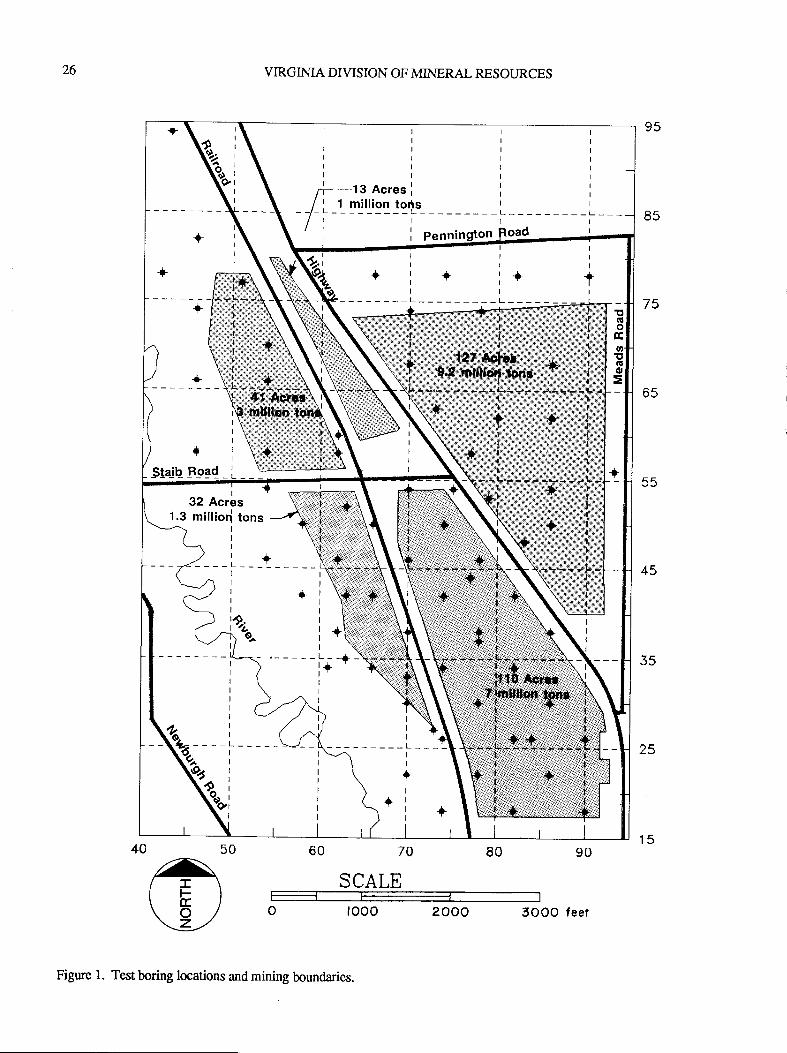
26 VIRGINIA DIVISION OF MINERAL RESOURCES
60 70 E0 90
SCALEI
O IOOO 2OOO 3OOO feet
rF--ts Acres I
I ', 1 million toqts
/ | ---i__-- -:-
I
I
I
I
I
I
I
I
L___
;a!oGotGo
=
Figure l. Test boring locations and mining boundaries.
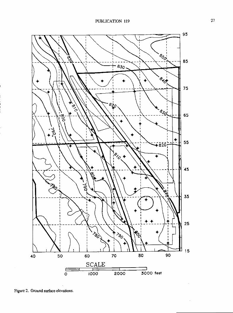
PUBLICATION 119
s0 60 70 E0
qnAT E'u vlllrjJ
O fOOO 2OOO 3OOO feet
21
I
I
I
---lI
:)
6
.o;
Figure 2. Ground surface elevations.
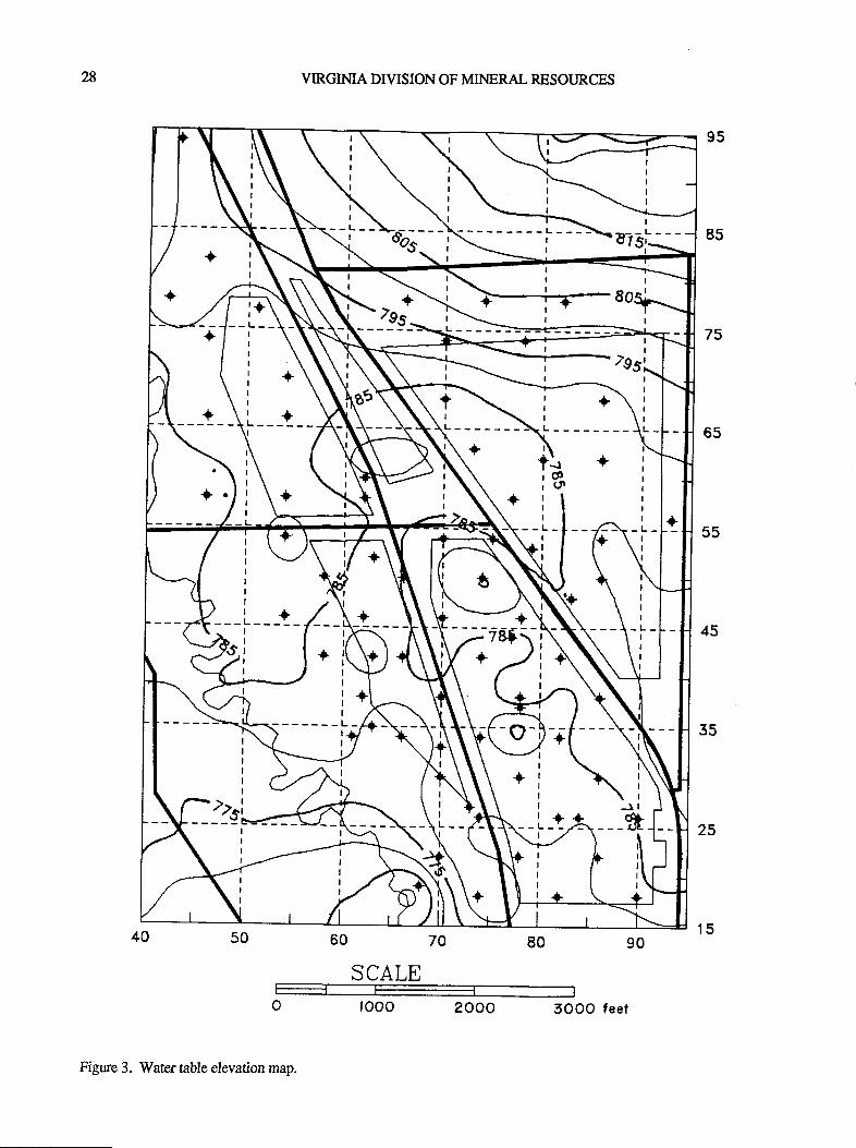
28 VIRGIMA DIVISION OF MINERAL RESOURCES
60 70 8o 90
qnAT E\J vfl'Ltl
O IOOO 2OOO SOOO feer
I
I
III
I
L
Figure 3. Water table elevation map.
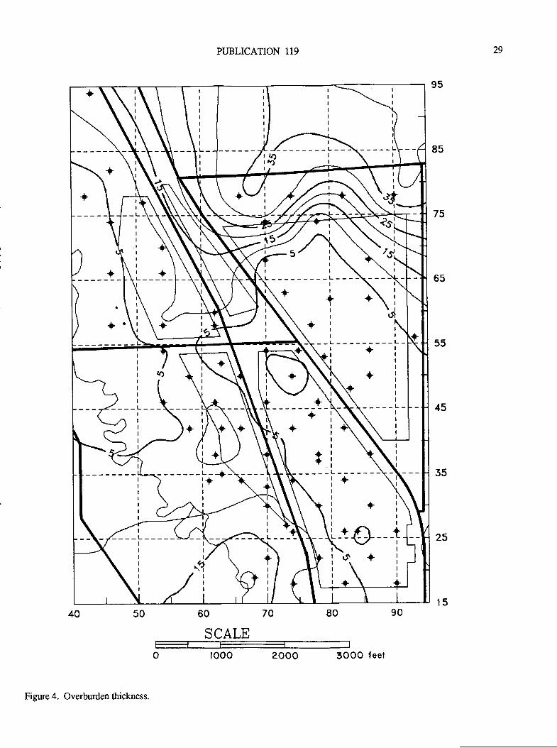
PUBLICATION 119
50 60 70 E0
SCALE
O IOOO 2OOO 3OOO feet
29
---L-
--iI
I
.at'\l/1
II
Figure 4. Overburden thickness.
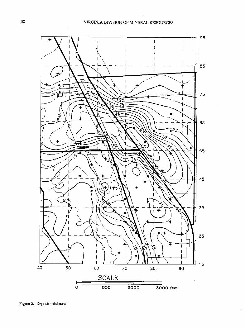
30 VIRGINIA DIVISION OF MINERAL RESOURCES
60 7A 30"
SCALE
O fOOO 2OOO SOOO feer
tlrtlttlttlL____L____Ltl
Figure 5. Deposit thickness.
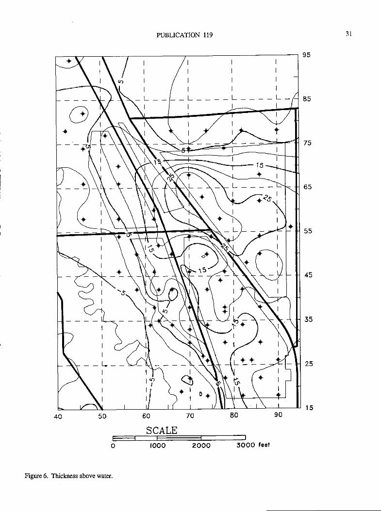
I
I
I
_L__
I
____L
I
I
I
I
I
I
I
L__
+\
?-
tl+l
PUBLICATION 119
50 60 70 E0 90
SCALE
O IOOO 2OOO 3OOO feet
JI
Figure 6. Thickness above water.
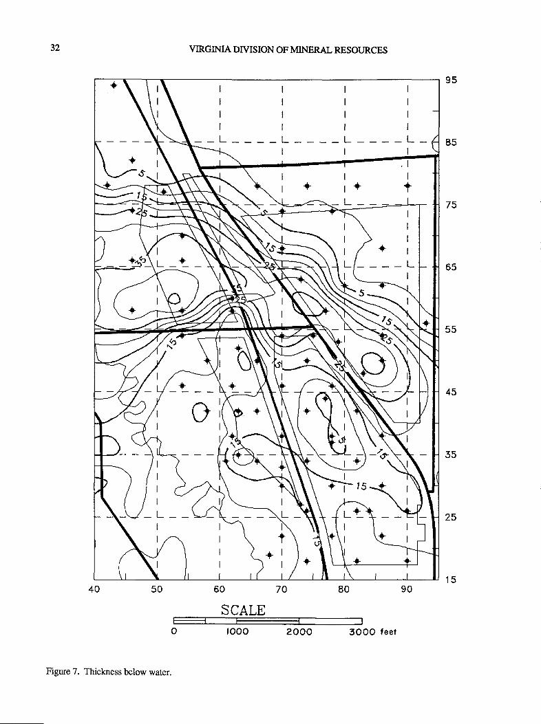
tllllllllltl
_L_ L___-L-_ttl
I
I
I
I
__L
I
I
I
I
LI
I
LI
I
L+_I
I
32 VIRGIMA DIVISION OF MINERAL RESOURCES
50 60 70 E0
SCALE
O IOOO 2OOO 3OOO feet
Figure 7. Thickness blow water.
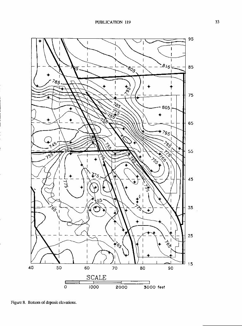
PUBLICATION 119
50 60 70 E0
qnAT El}Jvf1Lul-1l-_1|
O IOOO 2OOO 3OOO feet
JJ
I
I
L- Et
1_*__
9.)
Figure 8. Bottom of deposit elevations.
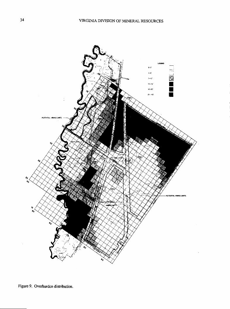
34 VIRGIMA DIVISION OF MINERAL RESOURCES
G3'
+e'
11-t5
r€-20'
21- 40'
TrWtII
Figure 9. Overburden disribution.
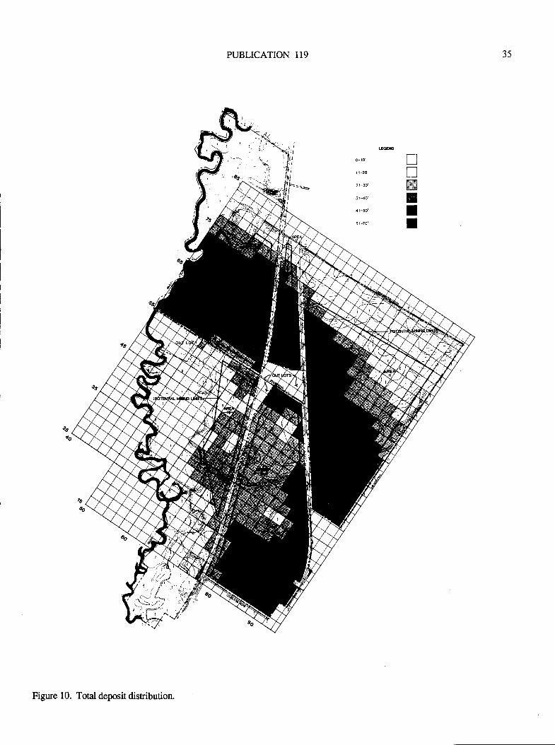
PUBLICATION 119
I
{,'
\.ia
35
o- ro
1 1-20
21-30
3 1-40'
41-50'
5 l-70'
IlWIII
rifS;:.A;&#^
Figure 10. Total deposit disribution.
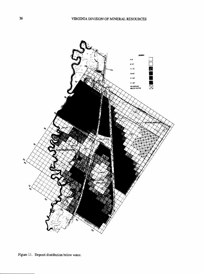
36 VIRGIMA DIVISION OF MINERAL RESOURCES
E@D
ero'
! t-t5'
1Fm'
2t-s
3r-{'rcD€ffi€oww^r
TnBIIIx
Figure I l. Deposit distribution below water.
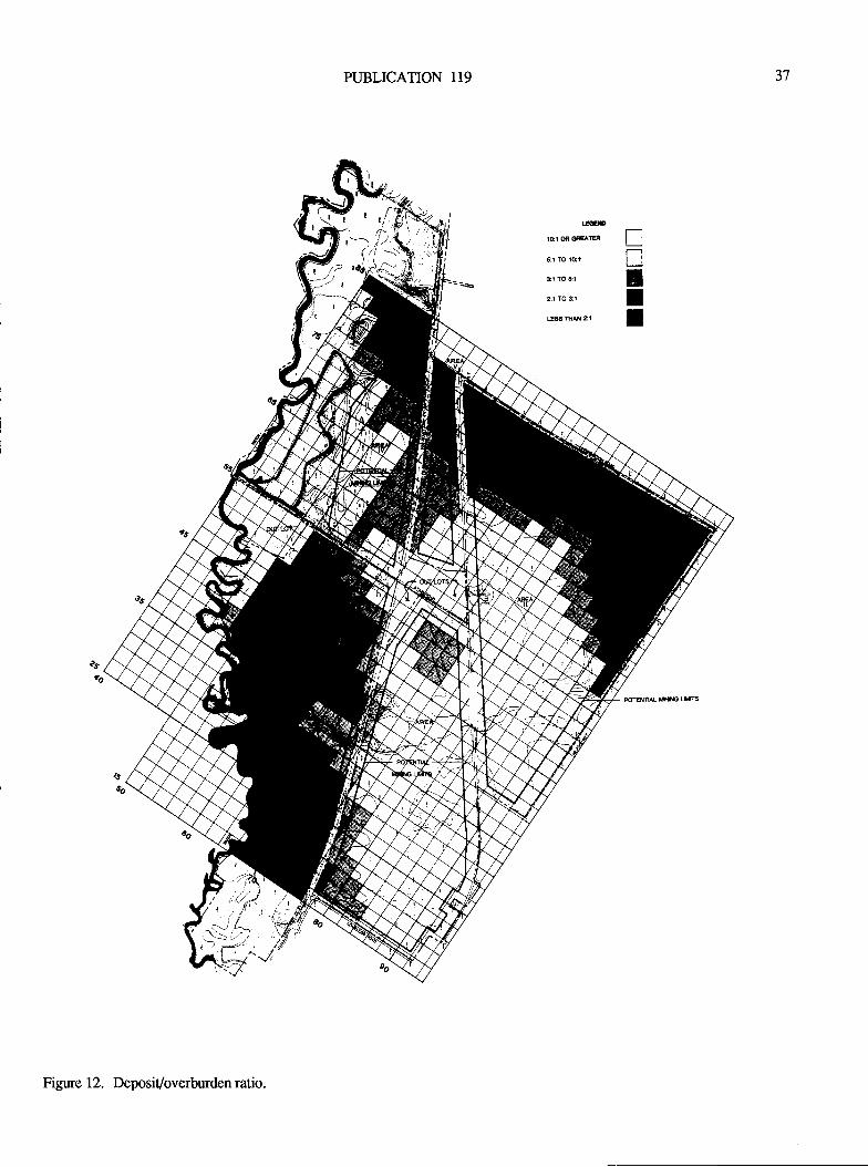
PUBLICATION 119 )t
l.EMlCI G C'EATER
5:r lO loi
31 lO 5l
al TO 3:1
ESg fiN a1
TntII
Figure 12. Deposit/overburden ratio.
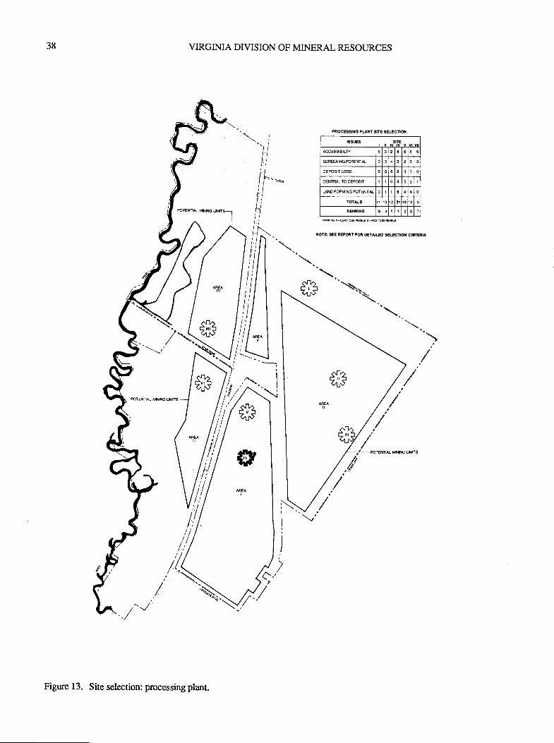
38 VIRGINIA DIVISION OF MINERAL RESOURCES
PFGES9re PLANT SITE SELECNOX
6SUEA strE
ACCESSIBTLt 5 3 5 5
$REENIrercrelm 0 3 3 3
oEPOSTT LOSS 5 5 5 3 3 0
CENRL TO OErcSI I 0
0 I 0
TOIAIS n t9 € 9
BANXIXO I 2
NOE: SEE RErcBT Ffi DflAILED SEUCnd CmRIA
Figure 13. Site selection: processingplant.
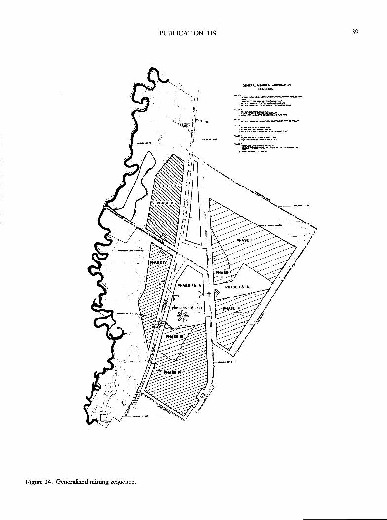
PUBLICATION 119 39
GENER L IIXIXO I UXDSXAHreSEOUErcE
*T **'-"^***
"'"f "** * -**""T"L***"^*"*,,
Figure 14. Generalized mining sequence.
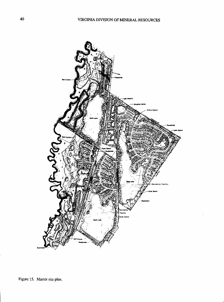
40 VIRGIMA DIVISION OF MINERAL RESOURCES
Figure 15. Master site plan.
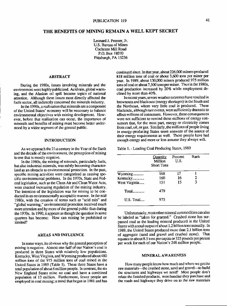
PUBLICATION 119
THE BENEFITS OF MINING REMAIN A WELL KEPT SECRET
I-eonard J. Prosser, Jr.U.S. Bureau of MinesCochrans Mill Road
P.O. Box 18070Pirsburgh, PA15236
4l
ABSTRACT
During the 1980s, issues involving minerals and theenvironment were highly publicized. Acid rain, global warm-ing, and the Alaskan oil spill became topics of nationalattention. Although these issues most directly affected ttpfuels sector, all indirectly concerned the minerals industry.
In the 1990s, a realization that minerals are a componentof the United States' economy will be necessary to balanceenvironmental objectives with mining developmenl How-ever, before that realization can occur, the imporlance ofminerals and benefits of mining must become better under-stood by a wider segment of the general public.
INTRODUCTION
As we approach the 21st century in the Year of the Eartltand the decade of tlte environment, tle perception of miningis one that is mostly negative.
In the 1980s, the mining of minerals, particularly fuels,but also industrial minerals, was subtly becoming character-ized as an obstacle to environmental protection. In the past,
specific mining activities were categorized as causing spe-
cific environmental problems. In the 1970s, State and Fed-
eral legislation, such as the Clean Air and Clean Water Acts,were enacted increasing regulation of the mining industry.The intention of the legislation was for mining to be con-ducted in an environmentally acceptable manner. In the mid1980s, with the creation of terms such as "acid rain" and"global warming," environmencal protection received muchmore attention and by more of the general public than duringthe 1970s. In 1990, itappean as though the question in somequarters has become: How can mining be prohibited orlimited?
AREAS ANDINFLUENCE
In some ways, its obvious why the general perception ofmining is negative. Almost one-half of our Nation's coal isproduced in three Sates with relatively low populations.Kentucky, West Virginia, and Wyoming produced about 480million tons of the 975 million tons of coal mined in theUnited States in 1989 (Table 1). These three States have atotal population of about 6 million people. In contrast, the sixNew England States mine no coal and have a combinedpopulation of 13 million. Furthermore, fewer people are
employed in coal mining; a trend that began in 1981 and has
continued since. In that year, about 226,000 miners prodrced818 million tons of coal or about 3,600 tons per miner peryear. In 1989, about 130,000 miners produced 975 milliontons of coal or about7,500 tons per miner. Thus in the 1980s,
coal production increased by 207o while employment de-
clined by more than 407o.In recentyears, severe weatherextremes have resulted in
brownouts andblackouts (energy shortages) in theSoutl and
the Norttreast, where very little coal is produced. These
blackouts, although rare events, were sufficiently dramatic toaffect millions of consumers. However, these consequences
were not sufficient to remind these millions of energy con-sumers that, for the most part, energy or electricity comes
from coal, oil, or gas. Similarly, the millions of people livingin energy-producing States seem unaware of the source oftheir energy requirements as well. These people have had
enough energy and more or less assume they always will.
Table 1. - Leading Coal Producing States, 1989
Ouantity Percent RankMillion U.S.
Short Tons
Wyoming...........Kentucky............West Virginia.....
Total 479
975U.S. Total....
168 17
160 16
151 15
I2J
Unfortunately, most other mineral commodities can also
be labeled as "taken for granted." Crushed stone has sur-passed coal as tlre leading mineral produced in the UnitedStates with a total output of about 1.2 billion tons annually. In1989, ttre United States produced more than 2.1 billion tons
of aggregate (sand and gravel and crushed stone). Thatequates to about 8.5 tons per capita or 325 pounds per person
per week for each of our Nation's 248 million people.
MINERAL AWARENESS
How many people know how much and where we gettieraw materials-the crushed stone, sand and gravel-to buildthe structures and highways we need? Most people don'trelate t}re finishedproducts, merchandise they purchase and
the roads and highways they drive on !o the raw materials
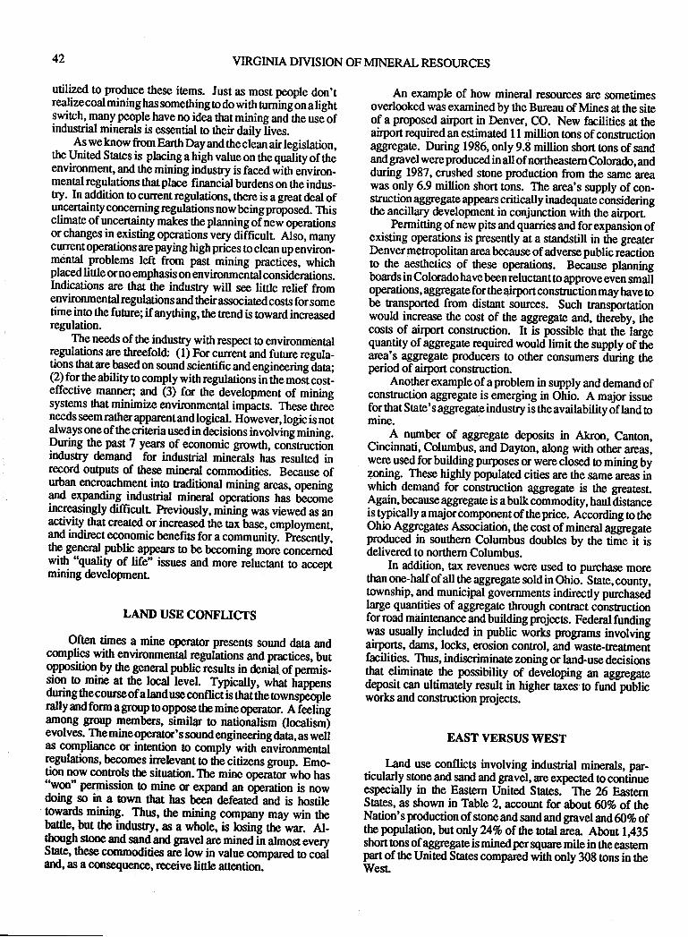
42 VIRGINIA DTVISION OF MINERAL RESOI.JRCES
utilPed tolroduce these items. Just as most people don'trealizecoal mininghas something o do with nrningbn atght9wjrch,-ryany people have no idea that mining and-the usJofindusrial minerals is essential to ttreir daily lives.
As we know from Earttr Day and the clean air legislation,the United Sratesis phcing a high value on the quatlty of theenvironment, and the mining indusry is faced with environ-menAl regulations thU place financial burdens on the indus_try. In addition to current regulations, there is a great deal ofuncercainty concerning regulations now being proposed. Thisclimate of uncertainty makes the planning ofnew operationsor changes in existing operations very difficull Also, manycurrent operations arepaying high prices to clean up environ_menal problems left from past mining practicis, whichplaced little or no emphasis on environmental considerarions.Indications are that the industry will see little relief fromenvironmental regulations and their associated costs for sometimeinto the funre; if anything, the uend is towardincreasedregulation.
The needs of the industry with respect to environmen0alregulations are threefold: (l) For cunent and future regula_tions that are based on sound scientific and engineeringiaa;(2) for the ability to comply with regularions in the moJt cost_effective manner; and (3) fo the development of miningsystems that minimize environmental impacts. These thrdneeds seem rather apparent and logical. However, logic is not{w1ys one of the criteria used in decisions involvinghining.P*ing the past 7 years of economic growth, constructionindustry demand for industrial mineials has resulted inrecord outputs of these mineral commodities. Because ofurban encroachment inlo faditional mining areas, openingand expanding indusrial mineral operations has trecomlincreasingly difficulr previously, mining was viewed as anactility ftat created orincreased the Ax base, employment,and indirect economic benefits for a community. neiently,the-general public app@rs to be becoming more concernedwit{ 'lualiry of life" issues and more dlucanr to acceprmining development
LAND USE CONFLICTS
Often times a mine operator presen8 sound data andcomplies with environmental regularions and practices, butoplosrtiq by thegencral public resulrs in den-ial. of permis_sion to mine at the local level. Tlpically, what happensduring thecourse of a land use conniit is ttraine rownqpeopterally and form a gloup to oppose the mineoperator. A ieelingamo-ng group members, similar to nationalism Qocalisrn)evolves.'The mineoperatc's sound engineeringda'a, as welias compliance or intention o comply with environmenlalregulations, becomes irrelwant to fire citizens group. Emo-tion now controls the situation. The mine operitc who has"won'permission to mine m expand an olration is nowdoing so in a town that has been defeated and is hostileowards mrling. Thus, the mining company may win thebattle, but the indrstry, as a wholC, is losin! the war. Al-though-s8oneand sandand gravel are mined in almosteveryState, these commodities arc low in value compared to coatand, as a cqlsequence, receive little afiention.
An example of how mineral resources are sometimesoverlooked was examined by the Bureau of Mines at the siteof a proposed airport in Denver, CO. New facilities at theairport required an estimated I 1 million lons of consfuctionaggregate. During 1986, only 9.8 million short tons of sandand gravel were produced in all ofnortheastern Colorado, andduring 1987, crushed stone production from the same areawas only 6.9 million short tons. The area's supply of con-sguctio.l aggregate appears critically inadequate consideringthe ancillary development in conjunction wittr ttre airporr -
Permiring of new pits andquarries and forexpansion ofexisting operations is presently at a standstill in ttre greaterDenver metropolitan area because of adverse public reactionto the aesthetics of these operations. Because planningboards in Colorado have been reluctant !o approve even smaloperations, aggregate for the 4irport construction may have Obe transported from distant sources. Such ransportationwould increase the cost of the aggregate and, thereby, thecosts of airport construction. It is possible that the largequantity of aggregate required would limit the supply of thearea's_ ag-gr€gate producers to other consumers during theperiod of airport construction.
Another example of a problem in supply and demand ofconstruction aggregate is emerging in Ohio. A major issuefor that Sbte's aggregateindusry is theavailability of land tomme.
A number of aggregate deposis in Akron, Canton,Cincinnati, Columbus, and Dayton, along with other aleas,wery usedfor building purposes or were closed to mining byzoning. These highly populated cities are the same arcas i;which demand for construction aggregate is the greatest.Again, because aggregate is a bulk commodity, haul distanceistypically a major component of the price. According o theOhio AggregatesAssociatioir, the cost of mineral aggregateproduced in southern Columbus doubles by the time it isdelivered to northern Columbus.
In addition, iax revenues were used !o purchase morethan one-half of all the aggregate sold in Ohio. State, county,township, and municipal governments indirectly purchasedlarge quantities of aggregate through contract constructionfor road maintenance and building projects. Federal fundingwas usually included in public worls programs involvingairports, dams, locks, erosion control, and wase-reatmentfacilities. Thus, indiscriminate zoning or land-use decisionsqrat eliminare rhe possibility of developing an aggregaredeposit can ultimately result in higher taxesto fund puUticworks and construction projects.
EASTVERSUSWEST
Iand use conflicts involving indusrial minerals, par-ticularly stone and sand and gravel, are expected to continueespecially in the Easrern United Sates. The ?6 EaslernStates, as shown in Table 2, account for about &% of theNation's production of stone and sand and gnvel and60% ofthe population, but only ?tl%o of the total area About l;435short ons of aggregate is mined per square mile in the easternpart of the United States compared with only 308 ons in theWest
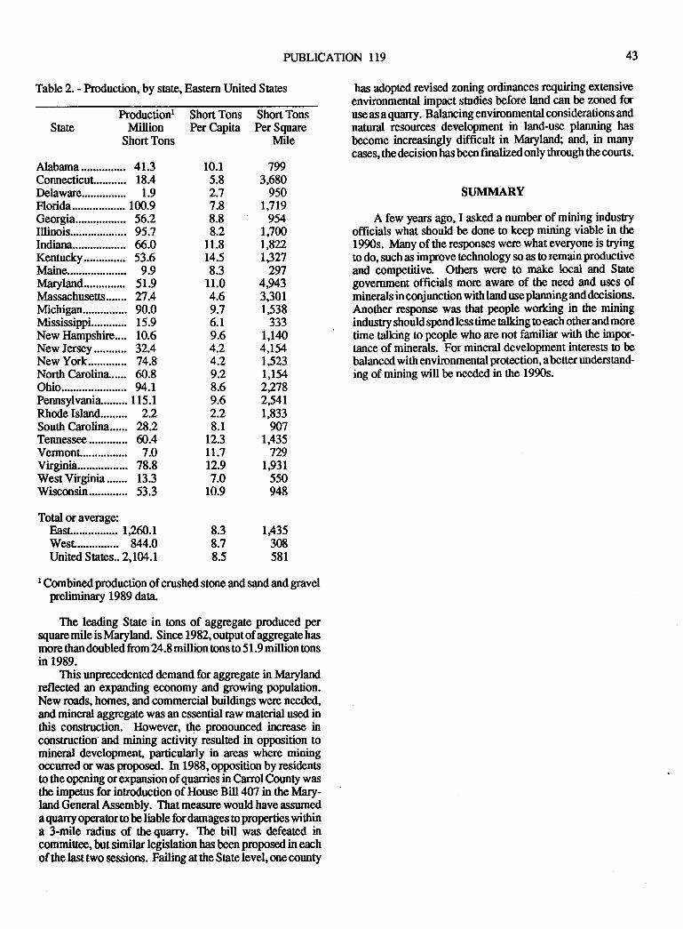
PUBLICATION I19 43
Table 2. - Production, by stale, Eastern United Sates
Productionr ShortTons ShortTonsState Million Per Capita Per Square
ShortTons Mile
has dopted revised zoning ordinances requiring extensive
environmental impact sfirdies before land can be zoned foruse as a quarry. Balancing environmental considerations andnatural resources development in land-use planning has
become increasingly difficult in lvlaryland; and, in manycases, the decision has been finalized only through the courts.
SI.JMMARY
A few years ago, I asked a number of mining industyofficials what should be done to keep mining viable in the1990s. lvlany of the responses were what everyone is tryingtodo, suchas improvetechnology so as toremainprodwtiveand competitive. Others wef,e !o make local and Sategovernment officials more aware of the need and uses ofminerals in conjunction with land use planning and decisions.Another response was that people working in the miningindustry shouldspendless time talking oeach otherandmoretime talking to people who are not familiar with the impor-tance of minerals. For mineral development interests to bebalanced with environmental protection, a better undentand-ing of mining will be needed in the 1990s.
Alabama............... 41.3Connecticul.......... 18.4Delaware............... 1.9Florida.................. 100.9Georgia................. 56.2Illinois.......... ......... 95.7Indiana.................. 66.0Kentucky.............. 53.6Maine.................... 9.9IvlaryIand.............. 51.9lvlassachusetts....... n.4Mchigan............... 90.0Mississippi............ 15.9New Hampshire.... 10.6New Jersey........... 32.4New York............. 74.8North C:rolina..... 60.8Ohio............. ......... 94.rPennsylvania......... I 15. IRhodeIsland......... 2.2South Carolim...... 28.2Tennessee............. ffi.4VermonL............... 7.0Virginia................. 78.8WesqVirginia....... 13.3Wisconsin............. 53.3
Total or average:East............... 1,260.1Wesr.............. 844.0United Sates.. 2,lM.l
l0.l 7995.8 3,6802.7 9507.8 rJrg8.8 9548.2 1JOOll.8 1,822t4.5 t,3278.3 297r1.0 49qz4.6 3,3019.7 1,5386.1 3339.6 1,1404.2 4,t544.2 1,5239.2 1,1548.6 22tt9.6 2,5412.2 1,8338.r w7t2.3 rA35rL.1 729r2.9 19317.0 55010.9 948
8.3 1F358.7 3088.5 581
l Combinedproduction of crushed stone and sandandgravelpneliminary 1989 data.
The leading State in tons of aggegate produced persquare mileis ltlaryland. Since 1982, output of aggregate hasmore thandoubled from 24.8 million ons to 51.9 million tonsin 1989.
This unprecedented demand for aggregate in lvlarylandreflected an expanding economy and growing population.New roads, homes, and commercial buildings were needed,and mineral aggregate was an essential raw material used inthis construction. However, the pronounced increase inconstruction and mining activity resulted in opposition tomineral development" particularly in areas where miningoccurred c was poposed. In 1988, opposition by residentso the opening or expansion of quarries in Carrol County wasthe impetus for introduction of House Bill 407 in the lMary-land General Assembly. That measure would have assumeda quary operator !o be liable for damages to properties withina 3-mile radius of the quarry. The bill was defeated incommifiee, but similar legislation has been proposed in eachof the last two sessions. Failing at the State level, one county

M VIRGIMA DIVISION OF MINERAL RESOURCES
At Luck Stone Corporation we have a motto "We Care".The motto reflects the attitude of the company towards itsemployees, its plantoperations and stone centers, its custom-en, its neighbors and the communities in which it operates.
As you know, "'We Care", "CommitrnentofExcellence"and other similar phrases are used liberally by many compa-nies. Luck Stone Corporation, however, does not onlybelieve in such ideals, it preaches them and most of allpractices them. It is through this commitment to caring forour employees, plant operations and stone centers, custom-ers, neighbors andcommunities thatluck Sonehas enjoyedthe success tlnt it has.
EMPLOYEES
EifSL we care for our employees. Every company cansay "People are Our Most Valuable Asset", but do they reattlrem that way? If employees are treated fairly they respondin a very positive manner. They respond by announcing totheir friends, neighbon and the community what a goodcompany they work for. This goes a long way in how acompany is perceived by individuals on the outside. You canimagine what happens when you have disgruntled employeestalking bad about the company.
How do we create this good will that is carried forwardout into the community?
1. We involve our employees - they are given oppor-tunities for input. Their supervisors and managers areavailable to discuss their ttroughts, suggestions and prob-lems. Our President personally visis with each em-ployee at his or her job location.
2. We give them training and reimburse them for jobrelated courses that are taken.
3. The production employees are challenged and re-warded by a "Productivity Improvement Proglam."
4. Employees are recognized for doing well:- Safety banquets- Service pins- Family picnics- Outings- Newsletter- Benefits such as Medical, Pension Plan
q. Profit sharing.
6. Mission Statement Whattheemployeecanexpectfrom the company and what the company expects fromthe employee.
PUBLICATION I19 45
CREATING A GOOD IMAGE
Joseph Andrews, Jr.Luck Stone Corporation
P. O. Box2!}682Richmond, Yhgnia23229
Weareforfirnate enough to have maintained anonunionenvironmentwhere employeeshave individualrighs andcan
strive for improvement and are personally recognized forttreir performance. Even though individuals are recognized,a team workconcept is utilized throughout - we all depend onone another in order to accomplish a clear cut mission. Weall have to haveamission ortarget. When wemeetthese goitls
we have eamed our success and therefore can take pride inourselves and in our company.
PRODUCTION
The work place is one of gmd equipment and facilities.Wereplaceold equipment,andbuild new, with the latestandmost up-to-date equipmentpossible. Mostof these improve-ments offer improved productivity but a lot of them make a
safer and cleaner work environment. Also they make us a
better neighbor.
l. Dust controls - such as collecors and high pressure
water trucks.
2. Noise reduction efforts, jaw crusher in the hole.
3. Stockpiling by conveyor vs. trucks.
We have our own SOP for blasting; more stringent thanmost standards for the communities where we are in business.
We have been able to increase production without addedovertime by automating parts of our plans. Not only is theremore stone produced but this method saves on electricalpower by leveling out power demands, reduces amount ofovertime, which also saves on wear and tear of our employ-ees.
We provide our plants with good equipment and facili-ties and we expect it to be taken care of. Good housekeeping
and beautification go hand-in-hand with good production.Pride in what they have to workwith causes employees to doa better job and to have pride in themselves and their com-pany.
CUSTOMER
This is where itakes a special effortby everyone withinthe company. Successful companies do notrely on their sales
force to be ttre only sales-oriented people within the organi-zation. That customer is the one who ultimately pays the bills.We constantly have to gain his respect and give him theservice he needs.
Of course, we have our sales force in the field making
46 VIRGINIA DIVISION OF MINERAL RESOIJRCES
calls on customers, but as one of our salesmen used to say hecould sell anyone the first load of stone but it woutd betheplant personnel who would keep him as a customer. Theoffice manager has toreceive his call and orderwith courtesvand professionalism, the loader ope.rator has to load his truclexpediently and carefully, and the product had to be producedto the required specifrcations and the office manager mustweigh them out in an efficient but quick manner. So thesalesman is right, it takes a lot of effort at ttrc plant to serviceand keep the customer.
Other things we do in our sales effort:
1. Work closely with customers to determine theirspecific requirements and schedule timely deliveries.
2. All orders, both large and small, are important !o usand receive the same prompt courteous attention.
3. Truckers are constantly reminded of their effect oncustomers and the community. Maintain a firm stand onlegal weight limits and required tarps. Hold courtesymeetings.
4. Work o achieve good communications betrpeen alldepartrnents to guarantee customer satisfaction.
5. See that our office managers and plant managers getto know our customers on a personal basis.
6 . Customers are invited to tour our plants and meet the'people who produce our products.
7. Ilave promotional ilems to give to our customers -hats, pens, pencils and other things.
8. Use pamphlets and brochures that are availablefrom the Virginia Aggregates Association, NationalSOne Association for distribution to interested custom-ers. An example is the erosion conEol brochure which isin constant demand.
9. Diqplay "Thank You" signs.
A lot of what we do to care fq the customer comes as aresult of surveying our employees - at all levels - to see howwe could service our customer best. lvlany of the suggestionsarebeingused- Ideas comefrom many unexpectedplaces, thethank you sign is an example.
Not only does a satisfied cuslomer offer mue sales, butthey too aremembers of a local community and if they speakwell of your company, it enhances your image.
NEIGHBORS
As much goes ino the consideration of neighbors inselectinganew siteasanything. Howcan weoperatehereandget along with property owners that surround us? We alsogive the same consideration to those who live near our
existing operations.Earthen berms have been one way in which we have
lessened the effect of our activities. They block the view ofthe operation, they muffle the sound and ttrey can be plantedand shaped to enhance the landscape.
We set out a seismograph, sometimes two, on everyblast. This not only gives a permanent record of the blast butitgives exposures to the neighbors ttratwe careenough aboutthem to put out the seismograph. It gives one an opportunityto talk to a complainant and have something positive to alkabout.
Along these lines, ourplant managers and area managersperiodically visit our neighbors. Certain ones at times arevisited by officers of the company. This personal contactgoes a long way.
We haveremoved snow from drivewaysandin suMivi-sions where the roads are not in ttre state system. In a veryunsystematic way we give stone to our neighbors. Free useof equipment for such purposes as welding and weighing ofgrain is allowed. We draw the line if we feel we are beingabused by our willingness to assist.
We beautify our enEances and maintain tlpm neat andclean. Maintaining the entrance is just as important, or evenmore important, than beautifying. This is what reminds ttreneighbors the most of what the quarry is about. So put on yourbest face, and then see that it is carried inside to the plant andpit area, notjust a facade.
We are most proud of our "About Face Awards" forbeautification and improvements to the environment andworking conditions at our plants. If you are not involved inmaking improvements towards a goal of entering a similarprogram - do so. You will find the results very rewarding.
We were before a local board for rezoning and one of thesupervisors stated he had read where we had won a nationalaward for beautification and he was impressed that we hadgone 0o such efforts. Programs that have been recognized assEong and credible offer a great deal to those who enter andwin.
Two unsolicited awards received at Luck were from the"Virginia Society of Iandscape Architecrs" (as caretakers ofttre land) and the local City and County Council of GardenClubs (for beautification at our entrance and along the road).Most of this is not so much what we did in ttre way oflandscaping or qpending big dollars, it was just maintainingtle grounds, as we call it, good housekeeping.
The impression you make on your neighbors or whatthey can see is the image they will have in their minds of thewhole operation.
COMMI.JNITY
Your neighbors are, to you, a very important part of thecommunity where you do business, but let's look at thehoader picure - your local community. You must have icsupport to run your business.
\Ve get involved by:
1. Donations & conributions, primarily:a. Fire-Rescue Squad
PUBLICATION 119
b. Youth organizations2. Talents of employees are used witlin the area to:
a. Speak to grcups and organizationsb. Serve on boards and commissions
3. Volunteers
4. Participate in local celebrations or parades
5. Exhibit at community fairs or trade shows
6. We give group tours
7. Hold open houses
8. Contact of local officials
9. We offer our facilities to groups for meetings
10. Our road equipment that travels through the com-munities is kept neat and clean.
Things in our industry can be changed and we must allstrive to change and make our industry more readily acceptedby the public. Our forefathers did not leave us with an easy
task, but let us take the initiative to make conducting businessin the minerals industry an easier task for those that mayfollow us.
I hope you have gained some ideas about improving theminerals industry's image and how to get more exposure forthe good things that are being done in the industry. But mostof all, this will not do us any good, unless we go back to ourindividual locations and emphasize to others how importantgood public relations is to the minerals industry and to eachof oul jobs. You have to make it happen. And believe me, thebenefits of a good image will pay dividends in many ways.
47

48 VIRGINIA DIVISION OF MINERAL RESOURCES
PUBLICATION TI9
IMPORTING CONSTRUCTION AGGREGATES TOTHE CONTINENTAL UNITED STATES
Mark J. Zdunczyk and Robert C. WalkerDunn Geoscience Corporation
12 Mero Park RoadAlbany, New York 12205
49
ABSTRACT
In recent years, there has been increasing interest !odevelop and promote aggegats imports to the United States.
Unlike cement, which has been imported for decades, import-ing of road aggegate by domestic and foreign producers has
been increasing along the eastern, southeastem, and Gulf ofMexico ports. Currently, other producers have either ex-plored or delineated areas of potential deposits for crushedstone which can be mined and shipped economically to theUnited States.
This interest is sparked by environmental concerns inopening new deposits in the United States. However, theimporters of aggregates must also be concemed with varyingaggegate specifications among the states. This paper willoutline and discuss these concerns and will also discuss somefactors regarding the production of construction aggregates,such as geology, market economics and transportation.
INTRODUCTION
Crushed stone and sand and gravel for use in road base,portland cement concrete and bituminous concrete mixturesis an important commodify in the United States. In 1989 ttre
total crushed stone sold in the U.S., according to tie U.S.Bureau of Mines, was estimated at 1220,000,000 short tons.Sand and gravel use for tle same end products accounted foran estimated 888,000,000 short tons in the same year (U.S.Bureau of Mines, 1990). Tonnages such as these haveincreased activity to explore and open new deposits through-out the United States. However, it has also become increas-ingly more difficult to permit a quarry site in urban areas
where the aggregate is needed.The complexity of permitting new deposits in the U.S. is
costly and time-consuming. This factor, along with others,has helped foster some companies, both foreign and domes-tic, to explore and develop deposits in Nova Scotia, New-foundland, Bahamas, Dominican Republic, Mexico, andJamaica to produce and ship aggregate to the United States.
Shipping bulk commodities by vessels on major water-ways is not new as cement has been shipped from foreignports to the United States and construction aggpgates havemoved via river courses to their destination for decades.
Generally, water transportation is less expensiveperton milethan rail or truck.
Perhaps the importing of construction aggegate on alarge-scale movement was Foster Yeoman's 1985 shipmentof granitic rock from Glensanda, Scotland to Houston, Texas.
Since then, major aggregate companies have sfategically
located potential quality stone for import purposes. Sand andgnvel impors increasedfrom 123,000 tons in 1983 to250,000tons in 1983 (U.S. Bureau of Mines, 1988-1989).
The importing of construction aggegates to the UnitedStates is controlled by many factors: environmental, specifi-cations, geology, production, and transportation costs (eco-
nomics).
ENVIRONMENTAL
One of the foremost factors which may play an importantrole for domestic producers 0o se€k rock sources in othercountries is environmental permitting. Like other miningindustries, crushed stone and sand and gravel must complywith various state, local, and federal regulations before the
site can be mined. The process is sometimes time-consumingand expensive procedure in most populous areas.
Pre-emption of aggregate deposits by local zoning laws
is becoming akey issue in their development. Proximity tothe consdmer is vital to the aggregate producer. To minimizetransportation costs, quarry sites need to be located close tothe population centers. Transportation costs can increase the
delivered price of the aggregate by over 100 percent of the
f.o.b. price. Implementation of land-use regulations is in-creasing throughout the United States. This tends to displace
aggregate production further away from its markelUrban growth (which creates much of the construction
aggregate market) has often expanded over once-potentialresoruces, mainly with sand and gravel deposits. A primeexample of urban encroachment was the focus of recent
studies by the Maryland Geological Survey. Within AnneArundel County, a suburban area near Baltimore and Wash-
ington, D.C., the effects of zoning, exhausted aggregate
resources, and urban encroachment were studied' In 1940,
nearly 70 percent of the original sand and gravel resources
were available to production. As of 1980, this percentage had
dropped to less than 20 percent (Langer, 1988). In addition,two proposed quarry sites were denied zoning change in the
Frederick Valley and one in Montgomery County in the State
of lvlaryland. In Georgia, it was reported that Vulcan Mate-rials Company has had a difficult time rezoning a proposed
site north of Atlanta. Convenely, it seems that foreign gov-
emments such as Canada, Bahamas andMexico promote newmining oppornrnities.
The monies from foreign investors, especially the United
States, have helped improve some local economies of these
areas and, in some places, employment by these operations
arc extremely welcome.
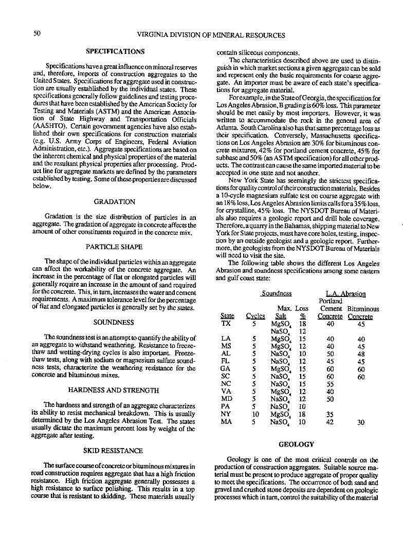
50
SPECIFICATIONS
Specifi cations have a great influence on mineral reservesg1{, thgrefore, imports of construction aggegates to theUnited S tates. Specifications for aggregate used in construc-tion are usually established by the individual states. Theses-necifigations generally follow guidelines and testing proce-dures that havebeen establishedby the American Society forTesting and Materials (ASTM) and the American Associa-tion of State Highway and Transportation Officials(AASIITO). Certain govemment agencies have also estab-lished their own specifications for construction materials(e.g. U.S. Army Corps of Engineers, Federal AviationAdminisradon, etc.). Aggregate specifications are based onthe inherent chemical and physical properties of the materialand the r-esultant physical properties after processing. hod-uct line for aggregate markets are defined by the parametersestablished by testing. Some of these properties are discussedbelow.
GRADATION
Gradation is the size distribution of particles in anaggregat€. The gradation of aggregate in concrete affects theamount of other constituents required in the concrete mix.
PARTICLE SHAPE
The shape of the individual particles within an aggegatecan affect the workability of the concrele aggregate.
-An
increase in the percentage of flat or elongated particles willgenerally require an increase in the amount of sand requiredfor the concrete. This, in turn, increases the water and cementrequirements. A maximum tolerance level for thepercentageof flat and elongated particles is generally set by the satei.
SOIJNDNESS
The soundness test is an atfempt O quantify the ability ofan aggegate o withstand weathering. Resistance to freeze-thaw and wetting-drying cycles is also important. Freeze-thaw tests, along with sodium or magnesium sulfate sound-ness t€sts, characterize the weathering resistance for theconcreoe and biurminous mixes.
HARDNESS AND STRENGTH
The hardness and strength ofan aggregate characterizesits ability to resist mechanical breakdown. This is usuallydetermined by the Los Angeles Abrasion Test. The stateiusually dictate the maximum percent loss by weight of theaggegate after testing.
SKIDP€SISTANCE
The surfacecourseofconcreteorbinrminous mixtures inroad construction requires aggregate that has a high frictionlasislange. High friction aggregate generally possesses ahigh resistance to surface polishing. This results in a topcoruse that is resisant !o skidding. These materials usually
VIRGINIA DIVISION OF MINERAL RESOURCES
Soundness
contain siliceous components.The characteristics described above are used to distin-
guish in which market sections a given aggregate can be soldand represent only the basic requirements for coarse aggre-gate. An importer must be aware of each state's specifica-tions for aggregate maferial.
Forexample, in the StateofGeorgia,the specification forlns Angeles Abrasion, B grading is 607o loss. This parametershould be met easily by most importers. However, it waswritten to accommodate the rock in the general area ofAtlanta. South carolina also has that same percentage loss astheir specification. Conversely, Massachusetts specifica-tions on Los Angeles Abrasion arc307o for bituminous con-crete mixtures,42Vo for portland cement concrete, 457o forsubbase and 507o (an ASTM specification) forall otherprod-ucts. The conEast can cause the same imported material to beaccepted in one state and not another.
New York State has seemingly the strictest specifica-tions for quality contol of their construction materials. Besidesa l0-cycle magnesium sulfate test on coarse aggregate withan 187o loss,Lns Angeles Abrasion limits callsfora 357o loss,for crystalline,45Vo loss. The I.{YSDOT Bureau of Materi-als also requires a geologic report and drill hole coverage.Therefore, a quarry in the Bahamas, shipping material to NewYork for State projects, must have core holes, testing, inspec-tion by an outside geologist and a geologic report. Further-more, the geologists from the NYSDOT Bureau of Materialswill need to visit the site.
The following table shows the different Los AngelesAbrasion and soundness specifications among some easternand gulf coast state:
lvlax. lossSalr %
MgsQ 18NaSQ 12MesQ 15
MgSQ 12NaSQ 10NaSQ 12MesQ lsNaSQ 15
NaSQ 15
MgSQ 12NaSQ 12NaSQ 10MgsQ 18NaSQ 10
GEOLOGY
L.A. AbrasionPortlandCement Bituminous
Concrete Concrete40 45
StateTX
LAMSAL
C!'cles5
555)555555105
FLGAscNCVAMDPAl{YMA
40 4040 4550 4845 4560 6060 60554050
3542 30
Geology is one of the most critical controls on theproduction of construction aggegates. Suiable source ma-terial must be present to produce aggregate ofproper qualityto meet the specifications. The occurrence of both sand andgravel and crushed stone deposits are dependent on geologicprocesseswhich in turn, conrol thesuitability of thematerial
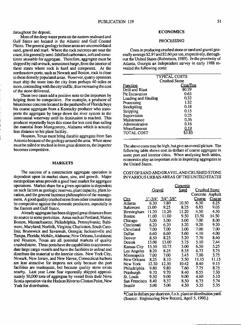
PUBLICATION 119 51
throughout the deposit.Mostof thedeep waterports on the eastern seaboardand
Gulf Sates are located in the Atlantic and Gulf CoastalPlains. The general geology in these areas are unconsolidatedsand, gravel and mad. Where the rock outcrops are near thecoast, it is generally semi-lithified carbonates, soft and some-times unusable foraggregate. Therefore, aggegate mustbeshipped by rail or truck, sometimes barge, from the interior ofthese states where rock is hard and competent. At thenortheastern ports, such as Newark and Boston, rock is closeto these densely populated areas. However, quarry operatorsmust ship the stone into the city from perhaps 40 miles ormore,contending with thecity haffic, thus increasing the costof the stone delivered.
These two cases add a positive note to the importen byhelping them be competitive. For example, a producer ofbituminous concrete located in the panhandle of Florida buyshis coane aggregate from a Kentucky producer who trans-ports the aggegate by barge down the river system to tleinlercoashl waterway until its destination is reached. Thisproducer reportedly buys ttris stone for less cost than railingthe material from Montgomery, Alabama which is actuallyless distance CI his plant facility.
Houston, Texas must bring durable aggegate from SanAnonio because of the geology around the area. When stonemustbe railed or trucked in from grea.t distances, the importerbecomes competitive.
MARKETS
The success of a construction aggregate operation isdependent upon is market share, size, and growth. Majormetropolitan areas provide a goodbase marketfor aggregateoperations. Market share fora given operation is dependenton such factors as geologic reserves, plant capacity, plant lo-cation, and the general business philosophies ofthe manage-menL A good quality crushed stone from othercountries maybe competitive against the domestic producers, especially inthe Easteni and Gulf States.
Already aggregate has been shipped great distances fromits source to some port cities. Areas such as Portland, Maine;Boston, Massachusetts; Philadelphia, Pennsylvania; Balti-more, lvlaryland; Norfolk, Virginia; Charleston, South Caro-lina; Brunswick and Savannah, Georgia; Jacksonville andTampa, Florida; Mobile, Alabama; New Orleans, Louisiana;and Houston, Texas are all potential markets of qualitycrushed stone. These ports have the capabilities to accommodate large cargo vessels and have the facilities to unload anddisFibute the material to the interior cities. New York City,Newark, New Jersey, and New llaven, Connecticut harborsare less attractive for imports not only because the portfacilities are inadequate, but because quality stone existsnearby. I ast year Lone Star reportedly shipped approxi-mat€ly 30,000 mns of aggregate by vessel from their NovaScotiaoperation viathe Hudson Riverto Clinton Point,NewYork for disribution.
ECONOIVtrCS
PROCESSING
Coss in producing crushed stone or sand and gravel gen-
erally average $2.97 and $2.60 per ton, respectively, through-out the United States (Robertson, 1989). In the proximity ofAtlanta, Georgia an independent survey in early 1988 re-vealed the following costs:
TYPICAL COSTSCrushed Stone
FunctionDrill and BlastPit ExcavationLoading and llaulingProcessingStockpilingStrippingSupervisionMaintenanceAdminisrativeMiscellaneousTOTALCOST
The above costs may be high, but give an overall picture. Thefollowing table shows cost in dollars of coarse aggregate insome port and interior cities. When analyzing both tables,economics play an important role in importing aggrcgates tothe United States.
COST OF SAND AND GRAVEL AND CRUSI{ED STONEIN VARIOUS URBANAREAS OFTHEUNITED STATES
ConcreteGravel Sand
Cost/Ton$0.29
0.630.32r.320.180.150.250.360.160.19
$3.85
c.!u l"-314"Atlanta 6.30Baltimore 15.mBirmingham 1I.20Boston 11.00Chicago 5.00Cincinnati 6.20Cleveland 7.00Dallas 6.60Denver 8.50Deroit 13.mKansas City 15.50Los Angeles 8.20Minneapolis 7.00New Orleans 8.25New York 12.30Philadelphia 9.80Piusburgh 9.70St.Inuis 9.50San Francisco 8.40Seattle 5.00
Crushed StoneConcrete Asphalt
Coarse Coarse6.30 8.256.85 9.054.50 4.5013.50 14.507.00 8.009.20 9.207.00 7.004.10 4.007.70 8.405.10 7.M6.50 5.256.73 5.757.00 5.7511.15 ll.l58.40 9.157.75 8.756.55 7.304.ffi 5.106.75 5.745.35 5.35
314"-318"7.809.25rr.2011.005.006.207.006.608.25
13.0010.758.257.008.10
12.309.809.709.008.375.00
10.508.25
11.209.505.005.203.005.605.205.753.008.353.455.50
rc.427.ffi8.409.008.504.50
*Cost in dollars per short ton, f.o.b. plantordisribution yard.(Source: Engineering New Record, April 5, 1990.)
52 VIRGINIA DIVISION OF MINERAL RESOURCES
TRANSPORTATION
Three major modes of aggregate ransporation in theUnited States are tuck, rail, and water. Baseline costs forthese tlpes of transporadon are generalized below:
Truck - $0.07 to 0.25lton-mile; $0.10 average.Rail - $0.02 o 0.08/ton-mile; $0.05 averageWater - Less than $0.01 o 0.05/ton-mile; 90.03 average
These baseline costs do not include factors, such asreloading, lock and port fees, and demurrage. These addedexpenses can have amajoreffecton the deliveredpriceof theaggregate. Due to increasing urban congestion, there hasbeen a Eend to a ton-hour rate for aggega0e disribution inurban areas. Local conditions also control ttre fansputationmethods and costs for consEuction aggegates. Truck trans-portation has hisorically dominated the movementof aggre-gate from plants to their markets. Tmck transport providesflexibility in meeting shifting market areas. In cases whererail or water tansport is used, the aggregat€ is shipped fromdisribution yards to the final consumer by truck.
As a direct result of the distancing of producers fromtheir market by urbanization, rail transport of aggregate odistibution yards has been increasing. Deregulation and isreduction in freight rates has also confibuted to this. Unittrains of 50 to 100 rail cars (usually 90 tons per car) shipaggregate into metropolitan areas such as Denver, Colorado.In other cases, a lack of local material that can meet specifi-cations has generated transportation of aggregate by rail. InVirginia, crushed granitic rock is railed from Emporia, Vir-ginia to the Suffolk-Norfolk metropolitan area along theAtlantic Coastal Plain. The lack of coarse aggregate materidalong the coast justifies this 60-miles rail haul.
Water transport of aggregates also occurs in select re-gions of the United States. Lack of adequate source materialproximal !o an urban area can encowage sup'pliers !o bargeaggregates in from another area. Skid resistance aggregate iscommonly shipped from lvlaryland to Atlantic coast citieswhere such mat€rial is needed.
How transportation affecs the import competitivenesswas approached by Timmons and llarben (1987). His ex-ample follows:
To reach a Gulf Coast market, aggegate from inlandsources incurs M.00 per ton in freight costs (by rail).With the avemge f.o.b. plantprice of $8.86 per ron, thisbrings the total price to $12.86 f.o.b. at the Gulf Coastdisribution yard. For Scottish granite, the otal price was$10.70 to $11.15 perton f.o.b. attheGulfCoastterminal.In boft cases, the cost for disribution to the final cus-tomer would be added.
SITES AND COMPAMES
Excluding those companies shipping material acrosslocal international boundaries, the following list of compa-nies indicates expanding interest of impors to the UnitedStates via oceanic shipping.
o Foster Yeoman Limited, Glensanda Quarry, Scotlandhas shipped gnnitic crushed stone to Houston, Texas startingin 1985.
o Ione Star Indushies, Auld Cove, Nova Scotia, shippedgranitic rock to Charleston, South Carolina, New York Sta0eand other eastern seaboard cities.
o DravoBasiclvlaterialsCompany,Freeport"GrandBaha-mas began in 1989 shipping limestone to Mobile, Alabamaand Tamp4 Florida
o Vulcan ldaterials Company is developing a limestorpquarry in the Yuca0anpeninsulaof Mexico. Shipments maybegin in late f 990 or 1991 to Houston, Texas and other GulfStates.
o TheNewfoundlandResources&MningCo.Ltd.,ownedby Explaura Holdings PLC, has recently (October 1989)taken fteir first shot (blas$ and may begin shipping limestoneto the eastern states. The quarry is located on the Port au PortPeninsula.
o lvlarcona Oceanic Minerals, Ltd. has been producinglimestone and aragonite from its operation at Sandy Caysouth of the Bahama Islands. Their production mainly is usedin the glass industry; however, some shipments were madefor construction purposes.
o Ideal Basics has been producing chemical gade lime-stone in the Dominican Republic and shipping it along theeast coast. Reports have indicated their interest in producingconstruction aggegate for import purposas.
o Riverside Construction Materials have interest in a sitein Nova Scotia,95 miles north of Yarmouth.
o Other sites which have been explored include one in theSoutleastem Dominican Republic near the Haitian border byVulcan Materials in 1986 before they settled on YucatanPeninsula According to the January, 1989 Rock Products
Mg@!!g Dravo Basic Materials Company is exploringpossible sites in Mexico. Reports have indicated that twocompanies have expressed interest in exploring the Baja ofMexico for aggregate with thoughts of shipping the materialby vessel into Los Angeles, California.
In Newfoundland, nearLong Harbour, a group of enfe-preneurs are developing interest in that site. The wharf andloading facility are in place from previous owners whoimported phosphate from Florida for their manufacturingprocess. The facility has shipped slag as a by-product fromtheir process to Jacksonville, Florida for use by Dravo insome of their construction pr-ojects.
Major companies are exploring other sites in Mexico,Caribbean Islands and Ireland. In January 1989, a newsletterpublished by the Geological Survey of Ireland stated thatseveral companies are examining the Ireland coast as a sourceof aggregate for the eastern United States.
PUBLICATION 119
SI.JMMARY
Thispaperhasbrieflyexplored some of the factorswhichdetermine whether an importer of aggregates to the UnitedStates can be competitive. It was determined that among thefive factors discussed, all have influenced in some mannerboth the importer and those wishing to become importers ofaggregate to the united saes.
o Environmental and zoning concerns have made it diffi-cult to open new qrlarry sites in populous areas in the UnitedStales where consruction aggregate is needed.
o Increased transportation costs related to higher unit costsper mile, longer dis0ances and newer truck weight laws haveincreased delivered costs.
o Specifications which are different in every state cancause some stone to be accepted in our State and not another.
o Costs of producing the product as related to energy andlabor may be less expensive in countries outside the UnitedStates; however, production costs for crushed stone remainessentially the same throughout the United States and othercountries.
Although impors of crushed stone and sand and gravelincreased since 1987, only 0.5 percent is consumed by theUnited States. Industry leaders seem very cautious whenasked the future impacts of imported aggregate to the Unit€dStates. The interest and development of these sites takescareful planning and cost accounting.
REFERENCES CITED
Langer, W.H., 1988, Natural Aggregates of the Conterminous United States: U.S. Geological Survey Bulletin 1594,33 p.
Robertson, J.L., 1989, Operating Cost Survey, RockProductsMagazine,v.92,n. l, p. 33.
Tepordei, V.V., 1989, Perspectives on Sand and Stone, RockProducts Magazine, v. 92, n. l, p. 42.
Timmons, BJ. and llarben, P.W., 1987, I{ave Aggegates-Will Travel Society of Mining Engineers Preprint Number87-131, 5 p.
U.S. Bureau of Mines, Mineral Commodity Summaries,1988-r990.
53

54 VIRGINIA DIVISION OF MINERAL RESOURCES
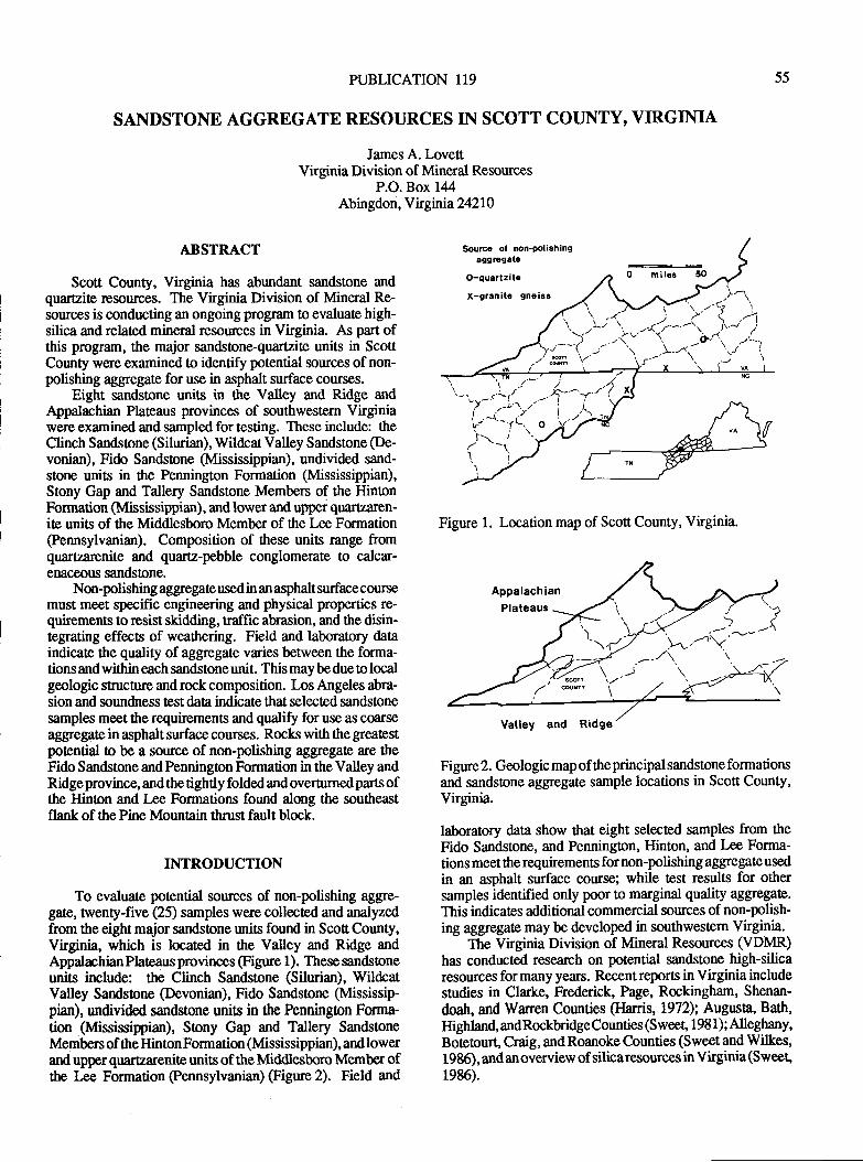
PUBLICATION I19
SANDSTONE AGGREGATE RESOURCES IN SCOTT COUNTY, VIRGINIA
James A. LovettVirginia Division of Mineral Resources
P.O. Box 144Abingdon, Ykgnia242l0
55
ABSTRACT
Scott County, Virginia has abundant sandstone andq:rlrlzitr resouces. The Virginia Division of Mineral Re-sources is conducting an ongoing program to evaluate high-silica and related mineral resources in Virginia. As part ofthis program, the major sandstone-quartzite units in ScottCounty were examined to identify potential sources of non-polishing aggegate for use in asphalt surface courses.
Eight sandstone units in the Valley and Ridge andAppalachian Plateaus provinces of southwestem Virginiawere examined and sampled for testing. These include: theClinch Sandstone (Silurian), Wildcat Valley Sandstone (De-vonian), Fido Sandsone (Mississippian), undivided sand-stone units in the Pennington Formation (Mississippian),Stony Gap and Tallery Sandstone Members of the HintonFormation (Mississippian), and lower and uppei quartzaren-ite units of ttre Middlesboro Member of the Lee Formation
@ennsylvanian). Composition of these units range ftomquartzarenite and quartz-pebble conglomerate to calcar-enacsors sandstone.
Non-polishing aggregate used in an asphalt surface coursemust meet specific engineering and physical properties re-quirements to resist skidding, traffic abrasion, and the disin-tegrating effects of weathering. Field and laboratory dataindicate the quality of aggregate varies between tle forma-tions and within each sandstone unit. This may be due to localgeologic structure and rock composition. Los Angeles abra-sion and soundness test data indicate that selected sandstonesamples meet the requirements and qualiS for use as cfrrseaggegate in asphalt surface courses. Rocks with the greatestpotential to be a soruce of non-polishing aggregate are theFido Sandstone and Pennington Formation in the Valley andRidge province, and the tightly folded and overturned parts ofthe Hinton and Lee Formations found along the southeastflank of the Pine Mountain thrust fault block.
INTRODUCTION
To evaluate potential sources of non-polishing aggre-gate, twenty-five (25) samples were collected and anaiyzedfrom the eight major sandstone units found in Scofi County,Virginia, which is located in the Valley and Ridge andAppalachian Plateaus provinces @igure 1). These sandsfoneunits include: the Clinch Sandstone (Silurian), WildcatValley Sandstone (Devonian), Fido Sandstone (Mississip-pian), undivided sandstone units in the Pennington Fsma-tion Mssissippian), Stony Gap and Tallery SandstoreMembers of the HintonFormation (Mississippian), and lowerand upper quarearenite units of the Middlesboro Member ofttre I€e- Formation @ennsylvanian) (Figue 2). Field and
Figure 1. Location map of Scott County, Virginia.
Figure 2. Gmlogic map of ttreprincipal sandstone formationsand sandstone aggegate sample locations in Scott County,Virginia.
laboratory data show that eight selected samples from theFido Sandstone, and Pennington, Hinton, and Lee Forma-tions meet the requirements for non-polishing aggregale used
in an asphalt surface course; while test results for othersamples identified only poor to marginal qualrty aggegate.This indicates additional commercial sources of non-polish-ing aggregate may be developed in southwestem Virginia.
The Virginia Division of Mineral Resources (VDMR)has conducted research on potential sandstone high-silicaresources for many years. Recent reports in Virginia includestudies in Clarke, Frederick, Page, Rockingham, Shenan-
doah, and Warren Counties (Ilarris, 1972); Augusta, Bath,Highland, andRockbridgeCounties (Sweet, 198 1); Alleghany,Boteourt, Craig, and Roanoke Counties (Sweet and Wilkes,1985), and anoverview of silicaresources in Virginia(Sweet,1986).
.8--I
^'t't'(
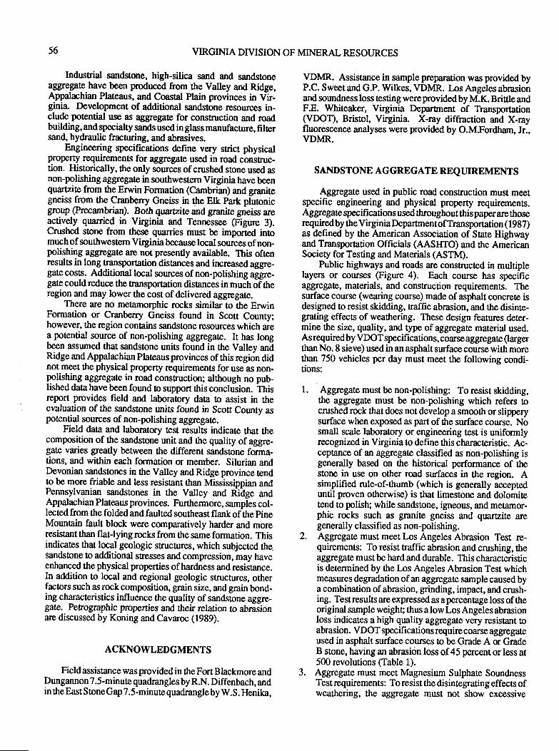
56 VIRGINIA DIVISION OF MINERAL RESOIJRCES
Industrial sandstone, high-silica sand and sandsloneaggregate have been produced from the Valley and Ridge,Appalachian Plateaus, and Coastal Plain provinces in Vir-ginia Development of additional sandstone resources in-clude potential use as aggregate for construction and roadbuilding, and specialty sands used in glass manufacture, filtersand, hydraulic fracnuing, and abrasives.
Engineering specifications define very strict physicalproperty requirements for aggregate used in road construc-tion. Historically, the only sources of crushed stone used asnon-polishing aggregate in southwestern Virginia have beenquartzite from the Erwin Formation (Cambrian) and granitegneiss from the Cranberry Gneiss in the Elk park pfuonicgroup (Precambrian). Both quartzite and granite gneiss areqctively quanied in Virginia and Tennessee (Figure 3).Crushed stone from these quarries must be imported inomuch of southwestern Virginia because local sources of non-polishing aggregate arc not presently available. This oftenresults in long nansportation distances and irrcreased aggre-gate costs. Additional local sources of non-polishing aggre-gatecouldreduce the ransportation distances in much of theregion and may lower the cost of delivered aggregate.
There are no metamorphic rocks similar 0o the ErwinFormation or Cranberry Gneiss found in Scott County;however, the region contains sandstone resources which area potential source of non-polishing aggregate. It has longbeen assumed that sandstone units found in the Vallev andRidge and Appatachian Plateaus provinces of this region didnot meet the physical property requirements for use as non-polrling aggregate in road consruction; although no pub-lished data have been found to support this conclusion. thisreport provides field and laboratory data to assist in theevaluation of the sandstone units found in Scott County aspotential sources of non-polishing aggregate.
Field daa and laboralory test results indicate Ont thecomposition of the sandstone unit and ttre quality of aggre-gate varies greatly betrpeen the different sandstone forma-tions, and within each formation or mernber. Silurian andDevonian sandstones in the Valley and Ridge province tendto be more friable and less resistant than Mississippian andPennsylvanian sandstones in the Valley and Ridge andAppatachian Plateaus provinces. Furilrermore, sampies col-lected from the folded and faulted southeast flank of the pineMounain fault block were comparatively harder and moreresistant than flat-lying rocks from the same formation. Thisindicates that local geologic strucfires, which subjected the_sandstone to additional stresses and compression, may haveenhanced the physical properties ofhardness and resiitance.In addition to local and regional geologic structures, otherfactors such as rock composition, grain size, and grain bond-ing characteristics influence the quality of sandstnne aggre-gate. Petrogmphic properties and their relation to abrasionare discussed by Koning and Cavaroc (1989).
ACKNOWLEDGMENTS
Field assistance was provided in ttre Fort Blackmore andDungannon 7.5-minute quadrangles by R.N. Diffenbach, andin theEast StoneGap 7.5-minute quadrangle by W.S. Henika,
VDMR. Assistance in sample preparation was provided byP.C. Sweet and GP. Wiftes, VDMR. los Angeles abrasionand soundness loss testing were provided by M.K. Brittle andF.E. Whiteaker, Virginia DeparEnent of Transportation(VDOT), Bristol, Virginia. X-ray diffraction and X-rayfluorescence analyses were provided by O.M.Fordham, Jr.,VDMR.
SANDSTONE AGGREGATE REQTIIREMENTS
Aggregate used in public road construction must meetspecific engineering and physical property requirements.Aggregate specifications used throughout thispaperarethoserequired by the Virginia Department of Transportation ( I 987)as defined by the American Association of State Highwayand Transporation Officials (AASlffO) and ttre AmericanSociety for Testing and Materials (ASTM).
Public highways and roads are constructed in multiplelayers or courses @gure 4). Each course has specificaggregata, materials, and construction requirements. Thesurface course (wearing course) made of asphalt concrete isdesigned to resist skidding, traffic abrasion, and the disinte-grating effects of weathering. These design featurcs deter-mine the size, quality, and type of aggregate material used.Asrequiredby VDOTspecifications, coarseaggegate Qargerthan No. 8 sieve) used in an asphalt surface course with morethan 750 vehicles per day must meet the following condi-tions:
1. Aggegate must be non-polishing: To resist skidding,the aggregate must be non-polishing which refers ocrushed rock ttrat does not develop a smooth or slipperysurface when exposed as part of the surface course. Nosmall scale laboratory or engineering test is uniformlyrecognized in Virginia to define this characteristic. Ac-ceptance of an aggregate classified as non-polishing isgenerally based on the historical performance of thestone in use on other road surfaces in the region. Asimplified rule-of-thumb (which is generally accepteduntil proven othenvise) is that limestone and dolomitelend to polish; while sandsone, ign@us, and metamor-phic rocks such as granite gneiss and qufizite aregenerally classified as non-polishing.
2. Aggregate must meet Los Angeles Abrasion Test re-quirements: To resist naffic abrasion and crushing, theaggregate must be hard and durable. This characteristicis determined by the los Angeles Abrasion Test whichmeasures degradation of an aggregate sample caused bya combination of abrasion, grinding, impact, and crush-ing. Test results are expressed as a percentage loss of theoriginal sample weighg thus a low Los Angeles abrasionloss indicates a high quality aggegare very resistant toabrasion. VDOT specifications requirecoarse aggregateused in asphalt surface courses to be Grade A or GradeB stone, having an abrasitin loss of45 percent or less at500 revolutions (Table 1).
3. Aggregate must meet Magnesium Sulphate SoundnessTest requirements: To resist the disintegrating effects ofweatlering, the aggregate must not show excessive
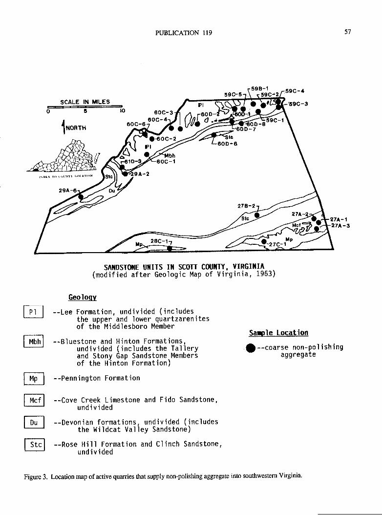
SCALE IN MILES
PUBLICATION 119
60c-360c-
57
o6tlronrnI
27A-',l?7A-3
SAIIDSTOIIE UIIITS IlI SCOTT COUIITY, YIRGI]IIA(modified after Geologic Map of Virginia, 1963)
rl@
E@EE
Geoloqv
--Lee Formation, undivjded (includesthe upper and lower quartzarenitesof the Middlesboro Member
--Bluestone and Hinton Formations,undivided (includes the Talleryand Stony Gap Sandstone.Membersof the Hintoh Formatjon)
--Penn'ington Formation
--Cove Creek Ljmestone and Fido Sandstone,undivided
--Devonian formations, undivided ('includesthe Wildcat Valley Sandstone)
--Rose Hjll Formation and Clinch Sandstone,undivided
Sanle Location
| --coarse non-po1 ish'ingaggregate
\0ott
Figure 3. Location map of active quanies that supply non-polishing aggegate into southwestern Virginia.
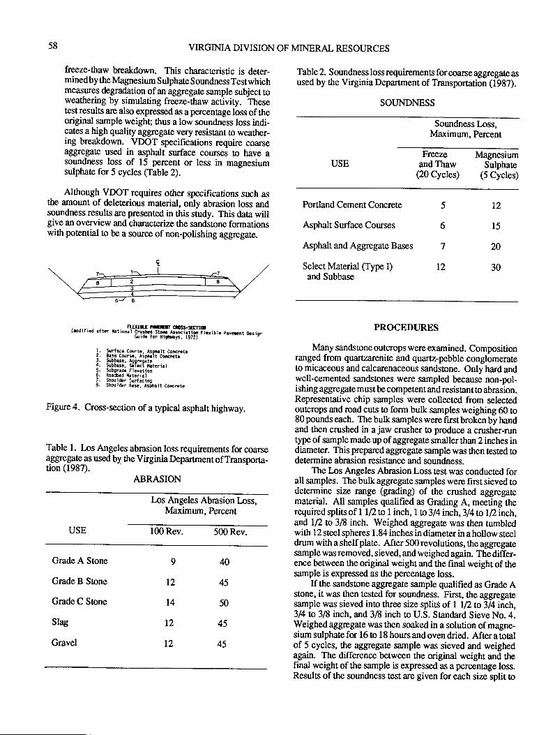
58 VIRGINIA DIVISION OF MINERAL RESOURCES
freeze-thaw breakdown. This characteristic is deter-minedby the lvlagnesium Sulphate Soundness Testwhichmqslres degradation of an aggregate sample subject toweathering by simulating freeze-thaw activity. Thesetest results are also expressed as a percentage loss of theoriginal sample weight; thus a low soundness loss indi-cates a high quality aggegate very resistant !o weather-ing breakdown. VDOT specifications require coaxseaggegate used in asphalt surface courses to have asoundness loss of 15 percent or less in magnesiumsulphate for 5 cycles (Table 2).
Although VDOT requires other specifications such asthe amount of deleterious material, only abrasion loss andsoundness results are presented in this study. This daA willgive an overview and characterize the sanditone formationswi*r potential to be a source of non-polishing aggregate.
. N.gII.f DEII G'-5ITTIC(D0rrrco atr.r t.tion.l Cruthd Stil.lrsirtid Fl.riblc p.ycnt ltliign6uide for Higlr.ys, 1972)
Figure 4. Cross-section of a typical asphalt highway.
Table 1. Los Angeles abrasion loss requirements for coarsea€i€iregat€ as used by the Virginia Department of Transporta-tion (1987)'
ABRA'T.N
L,os Angeles Abrasion lnss,Maximum, Percent
USE 100 Rev. 5ffiRev.
Grade A Stone
Grade B Sone
Grade C Stone
Slag
Gravel
Table 2. S oundness loss requirements for coarse aggregate asused by the Virginia Depafiment of Transportation (1987).
SOUNDNESS
Soundness Loss,Maximum, Percent
USEFrenzn lvlagnesium
and Thaw Sulphate(20 Cycles) (5 Cycles)
Portland Cement Concrete
Asphalt Surface Courses
Asphalt and Aggregate Bases
Select Material (Type I)and Subbase
PROCEDURES
Many sandsOne outcrops were examined. Compositionranged from quartzarenite and quartz-pebble conglomerateto micaceous and calcarenaceous sandstone. Only hard andwell-cemented sandstones were sampled because non-pol-ishing aggregate mustbe competent and resistant to abrasion.Representative chip samples were collected from selectedoutcrops and road cuts !o form bulk samples weighing 60 to80 pounds each. The bulk samples were first broken by handand then crushed in a jaw crusher o produce a crusher-runtype of sample made up of aggegate smaller than 2 inches indiameter. This prepared aggregate sample was then tested todetermine abrasion resistance and soundness.
The Los Angeles Abrasion Loss test was conducted forall samples. The bulk aggregate samples were first sieved todetermine size range (grading) of the crushed aggregatematerial. All samples qualified as Grading A, meeting therequiredsplits of I U2n I inch, 1to3/4inch,3l4nt|inch,and I2 to 3i8 inc$. Weighed aggregatg was then rumbledwith I 2 steel spheres I . 84 inches in diameter in a hollow steeldrum with a shelf plate. After 500 revolutions, the aggegatesample was removed, sieved, and weighed again. The differ-ence between the original weight and the final weight of thesample is expressed as the percentage loss.
If the sandstone aggregate sannple qualified as Grade Astone, it was then tested for soundness. First, the aggegatesample was sieved into three size split$ of 1 12 to 3/4 inch,3/4 to 318 inch, and 36 inch to U.S. Srandard Sieve No.4.Weighed aggregate was then soaked in a solution of magne-sium sulphate for 16 to 18 hours and oven dried. After a totalof 5 cycles, the aggregate sample was sieved and weighedagain. The difference between the original weight and thefinal weight of the sample is expressed as a percentage loss.Results of the soundness test are given for each size split to
t2
l5
20
30
5
6
7
t2
l. Slrfacc Course, Arplialt Concrcta?. !.se Course, Asphlt CftrctrJ. $DDrsc. Aaqrdata4. Subbisr, Sileci xatcrial5. Subgradr Eleyation6. Roadbcd llat.rial7. Shouider:urfacino8. Shoul4er 8a5., Ar;h.lt Concrotc
40
45
50
45
45
9
12
t4
T2
T2
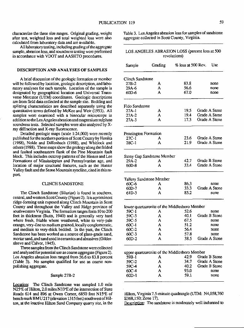
PUBLICATION 119 59
chnactet'ae the three size ranges. Original grading, weightafter test, weighted loss and total weighted loss were alsocalculated from laboratory data and are available.
All laboraory testing, including grading of the aggregatesample, abrasion loss, and soundness testing were performedin accordance with VDOT and AASHTO procedures.
DESCRIPTION AND ANALYSES OF SAMPLES
A brief discussion of the geologic formation or memberwill be followed by location, geologic description, and labo-ratory analyses for each sample. Location of the sample isdesignated by geographical location and Universal Trans-verse Mercator GfnO coordinates. Geologic descriptionsare from field data collected at the sample site. Bedding andsplitting characteristics are described separately using thequantitative terms defined by McKee and Weir (1953). Allsamples were examined with a binocular microscope inaddition o the Los Angeles abrasion and magnesium sulphatesoundness tests. Selected samples were also analyzed by X-ray diffraction and X-ray fluorescence.
Detailed geologic maps (scale l:24,000) were recentlypublished for the northern portion of Scott County by Henika(1988), Nolde and Diffenbach (1988), and Whitlock andothers ( 1 988). These maps show the geology along the foldedand faulted southeastern flank of the Pine Mountain faultblock. This includes outcrop patterns of the Hinton and LeeFormations of Mississippian and Pennsylvanian age, andlocation of major structunl features, such as the HunterValley faultandthe StoneMountrin syncline, citedin this re-port.
CLINCHSANDSTONE
The Clinch Sandstone (Silurian) is found in southern,central, and western ScoS County (Figure 2). It is a prominentridge-forming unit exposed along Clinch Mountain in ScottCounty and throughout the Valley and Ridge province ofsouthwestern Virginia. The formation ranges form 10 to 200feet in thickness @utts, 1940) and is generally very hardwhere fresh, friable where weathered, white to very-paleorange, very-fine !o medium grained, locally conglomeratic,and medium to very-thick bedded. In the past, the ClinchSandsone has been worked as a source ofglass-grade sand,mortar sand, and sandusedin ceramics andabrasives (Gilder-sleeve and Calver, 1945).
Three samples from the Clinch Sandstone were collectedand analyzed forpotential use as coarse aggegate (Figue 2).Ios Angeles abrasion loss ranged from 56.6 to 83.8 percent(fable 3). No samples qualified for use as c@rse non-polishing ag$egate.
Sample 278-2
Location: The Clinch Sandstone was sampled 1.0 mileN25"E of Hilton,2.0 miles N33"E of the intersection of StateRoads 614 and 896 at Owen Corner, 6850 feet N1598 ofbench mark BM U 2 I 7 (elevation 1 3 I 5 feet) southwest of Hil-ton, at the inactive Hilton Sand Company quarry site, in tle
Table 3. Los Angeles abrasion loss for samples of sandstone
aggegate collected in Scott County, Virginia.
LOS ANGELES ABRASION LOSS (percent loss at 500revolutions)
Sample Grading 7o loss at 500 Rev. Use
Clinch Sandstone278.229A460D-6
83.856.667.0
AAA
nonenonenone
Fido Sandstone274-r27p^-227A-3
AAA
19.5 Grade A Stone19.4 Grade A Stone17.3 Grade A Stone
Pennington Formation27C-r A28C-l A
23.6 Grade A Stone21.9 Grade A Sone
Stony Gap Sandstone Member294-2 A60D-8 A
42.7 Grade B Stone33.4 Grade A Stone
Tallery Sandstone Member60c-6 A60D-7 A61D-3 A
noneGrade A Stone
none
86.333.385.2
lower quartzarenite of the Middlesboro Member59C-l A59C-3 A59C-5 A60c-1 Affi,-2 A60c-3 A60D-2 A
52.6 none40.1 Grade B Stone67.5 none51.2 none56.4 none57.8 none38.5 Grade A Stone
upper quartzarenite of the Middlesboro Member598-159C-259C460c460D-1
AAAAA
42.9 Grade B Stone34.7 Grade A Sone40.2 Grade B Stone93.0 none59.1 none
Hilton, Virginia 7.5-minute quadmngle (UTM: N4,058,7608368,150; Tnne l7).Descriotion: The sandstone is moderately well indurated o
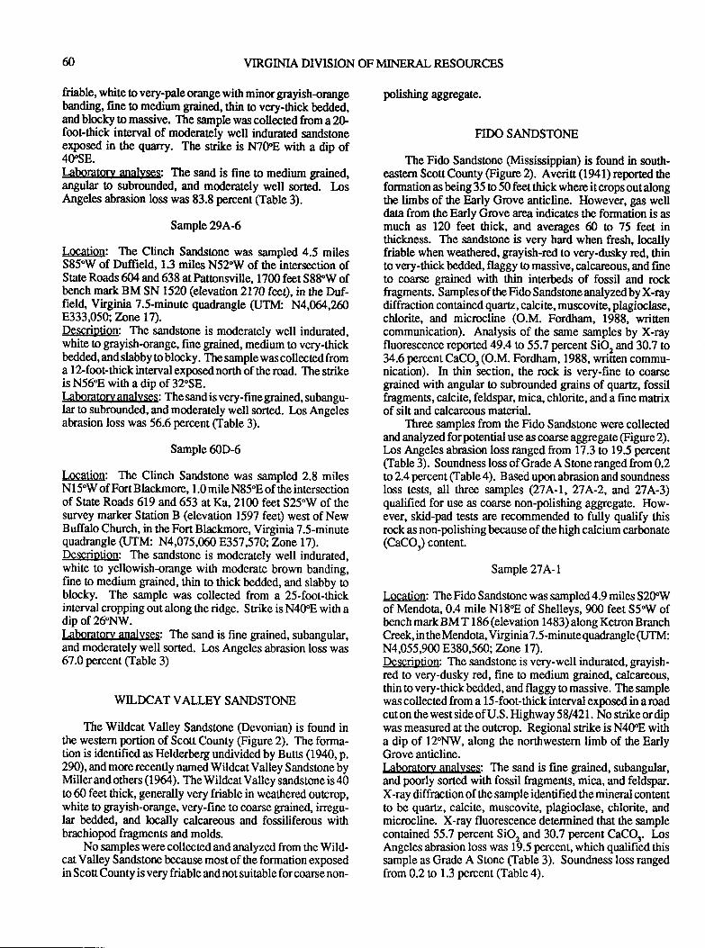
VIRGIMA DTISION OF MINERAL RESOURCES
friable, white o very-pale orange with minor grayish-orangebanding, fine to medium grained, thin to very-thick bedded,and blocky to massive. The sample was collected from a 2Gfoot-thick interval of moderately well indurated sandstoneexposed in the quarry. TIp snike is N7trE with a dip of40sE.Iaboratm.v analyses: The sand is fine to medium grained,angular o subrounded, and moderately well sorted. losAngeles abrasion loss was 83.8 percent Cfable 3).
Sample 29A-6
Location: The Ctnch Sandstone was sampled 4.5 milesS85'W of Duffield, 1.3 miles N52'W of the intersection ofState Roads 604 and 638 ar Panonsville, 1700 feet S88"W ofbench mark BM SN 1520 (elevation2lT0 feet), in rhe Duf-fiel( Virginia 7.5-minute quadrangle (UTM: N4,064,2608333,050; Tanel7'1.Description: The sandstone is moderately well indurated,white to grayish-orange, fine grained, medium to very-thickbedded, and slabby to blocky. The sample was collected froma l2-foot-thick interval exposed north of the road. The strikeis N5698 with a dip of 32"58.Laboratory analyses: The sand is very-fine grained, subangu-lar to subrounded, and moderately well sorted. Los Angelesabrasion loss was 56.6 percent (Table 3).
Sample 60D-6
l,ocation: The Clinch Sandstone was sampled 2.8 milesN 1 5'W of Fort Blackmore, 1.0 mile N85.8 of the intersectionof Slate Roads 619 and 653 at Ka,2100 feet S25.W of thesurvey marker Station B (elevation 1597 fee$ west of NewBuffalo Church, in the Fort Blackmore, Virginia 7.5-minutequadrangle (UTM: N4,075,060 8357,57 0; Zone l7).Description: The sandstone is moderately well indurated,white to yellowish-orange with moderate brown banding,fine to medium grained, thin to thick bedded, and slabby toblocky. The sample was collected from a 2S-foot-thickinterval cropping out along ttre ridge. Strike is N4ffE with adip of 26"NW.Laboratory anallrses: The sand is fine grained, subangular,and moderately well sorted. Los Angeles abrasion loss was67.0 percent (Table 3)
WILDCAT VALLEY SANDSTONE
The Wildcat Valley Sandstone (Devonian) is found intle western portion of Scott County (Figure 2). The forma-tion is identified as Helderberg undivided by Buts (1940, p.290), and more recently named Wildcat Valley Sandstone byMiller and others ( I 964). The Wildcat Valley sandstone is 40to 60 feet thick, generally very friable in weathered outcrop,white to grayish-orange, very-fine to coarse grained, irregu-lar bedded, and locally calcareous and fossiliferous withbrachiopod fragments and molds.
No samples were collected and analyzed from the Wild-cat Valley Sandstone because most of the formation exposedin Scott County is very friable and not suitable for coarse non-
polishing aggregate.
FTDO SANDSTONE
The Fido Sandstone (Mississippian) is found in south-eastem Scott County (Frgure 2). Averir (1941) reported treformation asbeing 35 to 50 feetthickwhereitsopsoutalongthe limbs of the Early Grove anticline. However, gas welldata from the Early Grove area indicates the formation is asmuch as 120 feet thick, and averages 60 o 75 feet inthickness. The sandsone is very hard when fresh, locallyfriable when weathered, grayish-red to very-dusky red, thinto very-thick bedded, flaggy to massive, calcareous, and fineto coarse grained with thin interbeds of fossil and rockfragments. Samples of the Fido Sandstone analyzed by X-raydiffraction contained quartz, calcite, muscovite, plagioclase,chlorite, and microcline (O.M. Fordham, 1988, wrirencommunication). Analysis of the same samples by X-rayfluorescence reported 49.4 w 55.7 percent SiQ and 30.7 to34.6 percentCaCOr(O.M. Fordham, 1988, wriiten commu-nication). In thin section, the rock is very-fine to coarsegrained with angular to subrounded grains of quartz, fossilfragments, calcite, feldspar, mica, chlorite, and a fine matrixof silt and calcareous material.
Three samples from the Fido Sandstone were collectedand analyzed forpotential use as coarse aggregate (Figure2).I-os Angeles abrasion loss ranged from 17.3 to 19.5 percent(Table 3). Soundness loss of Grade A Sone ranged from 0.2to 2.4 percent Cfable 4). Based upon abrasion and soundnessloss tests, all three samples (27A-1,27A-2, and 27A-3)qualified for use as coarse non-polishing aggegate. How-ever, skid-pad tests are recommended to fully qualify thisrock as non-polishing because of the high calcium carbonate(CaCQ) content.
Sample 27A-1
Location: The Fido Sandstone was sampled 4.9 miles S2OWof Mendota, 0.4 mile N18'Il of Shelleys, 900 feet S5'W ofbench mark BM T 186 (elevation 1483) along Ketron BranchCreek, in the Mendota, Virginia 7.5-minute quadrangle (UTM:N4,055,900 E380,560; Znne 17).Description: The sandstone is very-well indurated, grayrsh-red to very-dusky red, fine to medium grained, calcareous,thin to very-thick bedded, and flaggy o massive. The samplewas collected from a l5-foot-thick interval exposed in a roadcut on the west side of U.S. Highway 5 8/42 1 . No strike or dipwas measured at the outcrop. Regional srike is N48E witha dip of 12"NW, along the northwestern limb of the EarlyGrove anticline.I:boratory anal)rses: The sand is fine grained, subangular,and poorly sorted with fossil fragments, mica, and feldspar.X-ray diffraction of the sample identified the mineral contentto be quartz, calcite, muscovite, plagioclase, chlorite, andmicrocline. X-ray fluorescence determined that the samplecontained 55.7 percent SiO, and 30.7 percent CaCOr. LnsAngeles abrasion loss was 19.5 percent, which qualified thissample as Grade A Stone (Table 3). Soundness loss rangedfrom 0.2 to 1.3 percent (Iable 4).
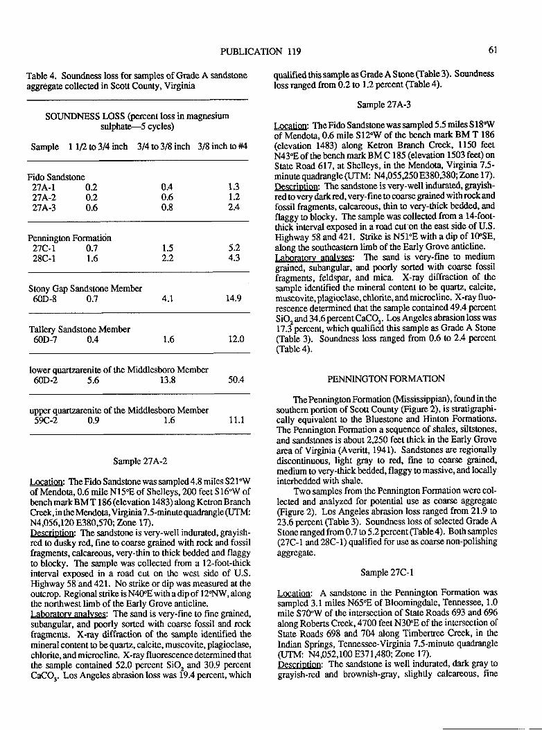
PUBLICATION 1I9 6L
Table 4. Soundness loss for samples of Grade A sandstoneaggregate collected in Scou County, Virginia
SOIJNDNESS LOSS (percent loss in magnesiumsulphate-5 cycles)
Sample ll2w3l4nch 3/4to3l8inch 3/8inchto*t4
Fido Sandstone27A-1 0.227A-2 0.2274-3 0.6
Pennington Formation27C-r 0.728C-l 1.6
Stony Gap Sandstone Member60D-8 0.7
Tallery Sandstone Member60D-7 0.4
lower quartzarenite of the Middlesboro MemberffiD-2 5.6 13.8
upper quartzarenite of ttre Middlesboro Member5rc.-2 0.9 1.6
Sample 274-2
Location: The Fido Sandstone was sampled 4.8 miles 52l"Wof Mendota, 0.6 mile N15"E of Shelleys, 200 feet S 16'W ofbench mark BM T 186 (elevation 1483) along Ketron BranchCreek, in the Mendota, Virginia 7.5-minute quadrangle (UTM:N4O56,120 E380,570; Zone 17).Description: The sandstone is very-well indurated, grayish-red to dusky red, fine to coarse grained with rock and fossilfragments, calcareous, very-thin o thick bedded and flaggyto blocky. The sample was collected from a l2-foot-thickinterval exposed in a road cut on the west side of U.S.Highway 58 and 421. No strike or dip was measured at theoutcrcp. Regional strike is N4trE with a dip of 12'NW, alongthe northwest limb of the Early Grove anticline.Laboratory analyses: The sand is very-fine to fine gtained,subangular, and poorly sorted with coarse fossil and rockfragments. X-ray diffraction of the sample identified themineral content to be quartz, calcite, muscovite, plagioclase,chlorite, and microcline. X-ray fluorescence determined thatthe sample contained 52.0 percent SiO, and 30.9 percent
CaCOr. Los Angeles abrasion loss was 19.4 percent, which
qualified this sample as Grade A Sone (Iable 3). Soundness
loss ranged ftom 0.2 to 1.2 percent (Table a).
Sample 274-3
Location: TheFido Sandstonewas sampled 5.5 miles S18'Wof Mendora, 0.6 mile S12'W of the bench mark BM T 186(elevation 1483) along Ketron Branch Creek, 1150 feetN439E of the bench mark BM C 185 (elevation 1503 feet) onState Road 617, at Shelleys, in ttre Mendota, Virginia 7.5-minute quadrangle (JTM: N4,055250 8380,380; Zone l7).Descriotion: The sandstone is very-well indurated, graytsh-red to very dark red, very-fine to coarse grained with rock andfossil fragments, calcareous, thin to very-tltick bedded, and
flaggy to blocky. The sample was collected from a l4-foot-thick interval exposed in a road cut on the east side of U.S.Highway 58 and 421. Strike is N51'E with a dip of IOSE,along the southeastern limb of the Early Grove anticline.Laboratorv analyses: The sand is very-fine to mediumgrained, subangular, and poorly sorted with coarse fossilfragments, feldspar, and mica. X-ray diffraction of thesample identified the mineral content to be quartz, calcite,muscovite, plagioclase, chlorite, and microcline. X-ray fluo-rescence determined that the sample contained 49.4 percent
SiO, and 34.6 percent CaCQ. Los Angeles abrasion loss was
l7.f percent, which qualifieO ttris sample as Grade A Stone(Table 3). Soundness loss ranged from 0.6 w 2.4 petcent(Table4).
1.3t.22.4
0.40.60.8
1.52.2
5.24.3
t4.94.1
12.01.6
50.4 PENNINGTON FORMATION
The Pennington Formation (Mississippian), found in thesouthern portion of Scott County (Figure 2), is stratigraphi-cally equivalent to the Bluestone and Hinton Formations.The Pennington Formation a sequence of shales, siltstones,
and sandstones is about 2,250 fentthick in the Early Grovearea of Virginia (Averitt, 1941). Sandstones are regionallydiscontinuous, light $ay to red, fine to coarse grained,
medium to very-thickbedded, flaggy to massive, and locallyinterbedded with shale.
Two samples from the Pennington Formation were col-lected and analyzed for potential use as coarse aggregate(Figure 2). Los Angeles abrasion loss ranged from 21.9 to23.6 percent (Iable 3). Soundness loss of selected Grade AStone ranged from 0.7 to 5.2 percent (Iable 4). Both samples(27C-I and 28C-1) qualified for use as coarse non-polishingaggregate.
Sample 27C-1
Location: A sandstone in the Pennington Formation wassampled 3.1 miles N659E of Bloomingdale, Tennessee, 1.0
mile S?SW of the intersection of State Roads 693 and 696along Roberts Creek, 4700 feet N3OE of the intersection ofState Roads 698 and 7M along Timbertree Creek, in theIndian Springs, Tennessee-Virgrnia 7.5-minute quadrangle(UTM: N4,052,100 8371,480; Tnne l7).Descriotion: The sandsone is well indurated, dark gray tograyish-red and brownish-gray, slightly calcareous, fine
11.1
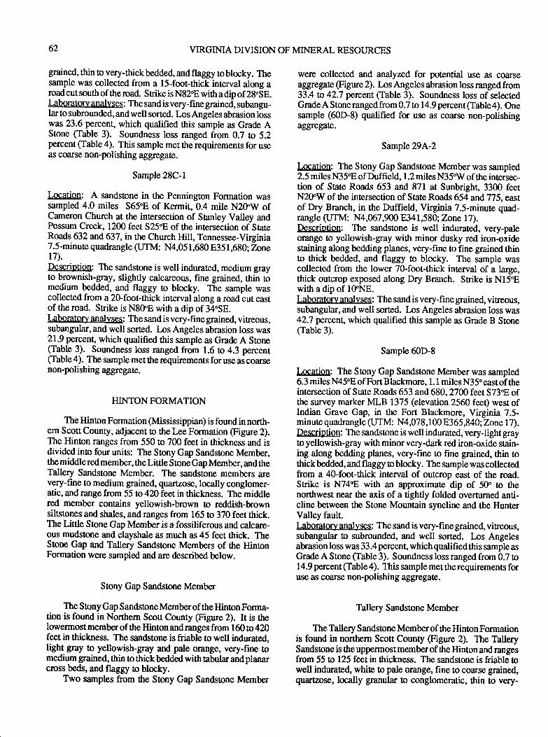
62 VIRGINIA DIVISION OF MINERAL RESOURCES
grained, thin to very-thick bedded, and flaggy to blocky. Thesample was collected from a lS-foot-thick interval along aroad cut south of the road. Srike is N829E with a dip of 28.SE.laborator.v analyses: The sand is very-fine grained, subangu-lar to subrounded, and well sorted. Los Angeles abrasion losswas 23.6 percent, which qualified this sample as Grade AStone (Iable 3). Soundness loss ranged from 0.7 to 5.2percent (Table 4). This sample met the requfuements for useas coarse non-polishing aggegat€.
Sample 28C-l
I"ocation: A sandstone in the Pennington Formation wassampled 4.0 miles S65.E of Kermit, 0.4 mile N2OW ofCameron Church at the intersection of Sanley Valley andPossum Creek, 1200 feet 525"8 of the intersection of stateRoads 632 and 637, in the Church Hill, Tennessee-Virginia7.5-minute quadrangle (UTM: N4,051,680 8351,680; Zoner7).Description: The sandstone is well indurated, medium grayto brownish-gray, slightly calcareous, fine grained, thin tomedium bedded, and flaggy to blocky. The sample wascollected from a 20-foot-thick interval along a road cut eastof the road. Strike is N8fE with a dip of 34"58.laboratory analyses: The sand is very-fine grained, vitreous,subangular, and well sorted. Los Angeles abrasion loss was21.9 perexnt, which qualified this sample as Grade A Stone(Iable 3). Soundness loss ranged from 1.6 ro 4.3 percent(Iable 4). The sample met the requirement"s for use as coarsenon-polishing aggregare.
HINTONFORMATION
The Hinton Formarion (Mississippian) is found in north-ern Scott County, adjacent to the Lee Formation @gure 2).The Hinton ranges from 550 to 7m feet in thickness and isdivided into four units: The Stony Gap Sandsrone Member,the middlered member, theLittle Stone Gap Member, andtheTallery Sandstone Member. The sandstone members arevery-fine to medium grained, quartzose, locally conglomer-atic, and range from 55 to 420 feet in thickness. The middlered member con[ains yellowish-brown to reddish-b,rownsiltstones and shales, and ranges from 165 to 370 feet ttrick.The Little Stone Gap Member is a fossiliferous and calcare-ous mudstone and clayshale as much as 45 feet ttrick. TheStone Gap and Tallery Sandstone Members of the HintonFormation were sampled and are described below.
Stony Gap Sandsoone Member
The Sony Gap Sandstone Memberof the Hinton Forma-tion is found in Northern Scott County (Figure 2). It is rtplowermost member of the Hinton andranges from 160 to 420feet in thickness. The sandstorp is friable !o well indurated,hght gay to yellowish-gray ard pale orange, very-fine !omedium grained, thin !o thick bedded with tabular and planarcross beds, and flaggy to blocky.
Two samples from the Stony Gap Sandstone Member
were collected and analyzed for potential use as coarseaggegat€ (Figure 2). Los Angeles abrasion loss ranged from33.4 to 42.7 percent (Table 3). Soundness loss of selectedGradeA Stonerangedfrom 0.7 to 14.9 percent(Table4). Onesample (60D-8) qualified for use as coarse non-polishingaggrcgate.
Sample 294-2
Location: The Stony Gap Sandstone Member was sampled2.5 miles N3 5'E of Duffield, 1.2 miles N3 5'W of the intersec-tion of State Roads 653 and 871 at Sunbright, 3300 feetN2fIV of the intersection of State Roads 654 and 775, eastof Dry Branch, in the Duffield, Virginia 7.5-minute quad-rangle (UTM: N4,067,m0 8341,580; ZonelT).Description: The sandstone is well indurated, very-paleorange o yellowish-gray with minor dusky red iron-oxidestaining along bedding planes, very-fine to fine grained thinto ttrick bedded, and flaggy to blocky. The sample wascollected from the lower 70-foot-thick interval of a large,thick outcrop exposed along Dry Branch. Strike is N159Ewith a dip of 10'NE.Laboratory analyses: The sand is very-fine grained, vitreous,subangular, and well sorted. Ios Angeles abrasion loss was42.7 prcens which qualified this sample as Grade B StoneClable 3).
Sample 60D-8
l,ocation: The Stony Gap Sandstone Member was sampled6.3 mile,s N45'E of FortBlackmore, 1.1 milesN35.eastof theintersection of State Roads 653 and 680,27C0 feet 573"8 ofthe survey marker MLB 1375 (elevation 2560 feet) west ofIndian Grave Gap, in the Fort Blackmore, Virginia 7.5-minute quadrangle ({.J'IM: N4,078,100 E365,840;Zone l7).Descriotion: The sandstone is well indurated, veryJight grayto yellowish-gray with minor very-dark red iron-oxide stain-ing along bedding planes, very-fine to fine grained, thin tothick bedded, and flaggy to blocky. The sample was collectedfrom a 4O-foot-thick interval of outcrop east of the road.Strike is N749E with an approximate dip of 50 to ttrenorthwest near the axis of a tightly folded overturned anti-cline between the Stone Mountain syncline and the HunterValley fault.Iaboratory analyses: The sand is very-fine grained, viEeous,subangular to subrounded, and well sorted. I-os Angelesabrasion loss was 33.4 percent, which qualified this sample asGrade A Stone (Table 3). Soundness loss ranged from 0.7 o14.9 percent (Table 4). This sample met tle requirements foruse as ccrse non-polishing aggregate.
Tallery Sandstone Member
The Tallery Sandstone Memberof the Hinton Formationis found in northern Scott County (Figure 2). The TallerySandstone is the uppermost member of the Hinton and rangesfrom 55 to 125 feet in thickness. The sandstone is friable owell indurated, white to pale orange, fine to coarse grained,quartzose, locally granular to conglomeratic, thin to very-
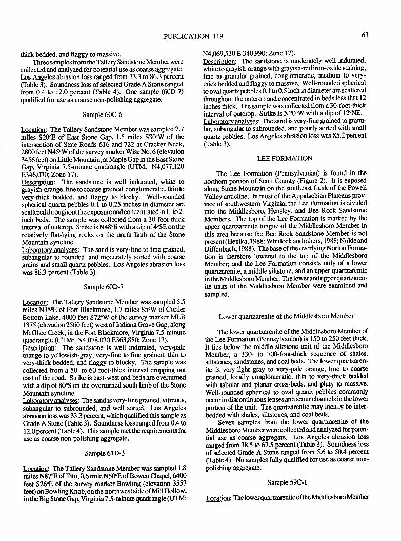
PUBLICATION 119 63
thick bedded, and flaggy to massive.Three samplesfrom the Tallery Sandstone Memberwere
collectedand analyzed forpotential use as coarse aggegate.Ios Angeles abrasion loss ranged from 33.3 to 86.3 percent(Table 3). Soundness loss of selected Grade A Stone rangedfrom 0.4 to 12.0 percent (Iable 4). One sample (60D-7)qualified for use as coarse non-polishing aggegate.
Sample 60C-6
Location: The Tallery Sandstone Member was sampled 2.7miles S2,OE of East Stone Gap, 1.5 miles S3OW of theintersection of State Roads 616 and722 at Cracker Neck,2800 feetN45"W of the survey marker Wise No. 6 (elevation3456 feet) on Little Mountain, at Maple Gap in the East StoneGap, Virginia 7.5-minute quadrangle (UTM: N4,077,1208346,0?0; T.r:lnel1).Description: The sandstone is well indurated, white tograyish-orange, fine to coarse grained,conglomeratic, thin tovery-ttrick bedded, and flaggy to blocky. Well-roundedspherical quartz pebbles 0.1 to 0.25 inches in diameter arescattered throughoutthe exposure and concenEatedin l- taz-inch beds. The sample was collected from a 30-foot-thickinterval of ourcrop. Strike is N48'E with a dip of 4'SE on therelatively flat-lying rocks on the north limb of the StoneMountrin syncline.Laboratorv anallrses: The sand is very-fine to fine grained,subangular to rounded, and moderately sorted with coarsegrains and small quartz pebbles. Ins Angeles abrasion losswas 86.3 percent Cfable 3).
SamPle 60D-7
l4gatiq: The Tallery Sandstone Member was sampled 5.5miles N359E of Fort Blackmore, 1.7 miles S5"V/ of CorderBotrom Iake, 4000 feet S72"W of the survey marker MLB1375 (elevation 2560 feet) west of Indiana Grave Gap, alongMcGhee Creek, in the Fort Blackmore, Virginia 7.5-minutequadrangle (UTM: N4,078,030 E363,880; Zone l7).Description: The sandstone is well indurated, very-paleorange to yellowish-glay, very-fine to fine grained, tttin tovery-thick bedded, and flaggy to blocky. The sample wascollected from a 5O. to 6&foot-thick interval cropping outeast of the road. Srike is east-west and beds are overturnedwith a dip of 8OS on tie overturned south limb of the StoneMountain syncline.Laboratorv anallrses: The sand is very-fine grained, vitreous,subangular to subrounded, and well sorted. Los Angelesabrasion loss was 33.3 percent, which qualihed this sample as
Grade A Stone (Table 3). Soundness loss ranged from'0.4 o12.0 percent (Iable 4). This sample met the requirements fon
use as c@rse non-polishing ag$egate.
Sample 6lD-3
Location: The Tallery Sandstone Member was sampled 1.8
miles N87:E of Tito, 0.6 mile N5trE of Bowen Chapel, 6400feet S26'E of the survey marker Bowling (elevation 3557feet) on Bowling Knob, on the northwest side of Mill Hollow,in the Big Sone Gap, VirginiaT.S-minute quadrangle (UTM:
N4,069,530 E 340,990; Zone l7).Description: The sandstone is moderately well indurated,white to grayish-orange with grayish-red iron-oxide staining,fine to granular grained, conglomeratic, medium to very-
thick bedded and flaggy to massive. Well-rounded spherical
!o oval quartz pebbles 0.1 to 0.5 inch in diameter are scatrered
throughout the outcrop and concentrated in beds less that 12
inchei thick. The sample was collected from a 30-foot-thickinterval of outcrop. Strike is N2trW with a dip of 12"N8.Laboratorv anallrses: The sand is very-fine grained to grcnu-
lar, subangular to subrounded, and poorly sorted with smallquartz pebbles. l,os Angeles abrasion loss was 85.2 percent
(Table 3).
LEE FORMATION
The Lee Formation @ennsylvanian) is found in the
northern portion of Scott County (Figure 2). It is exposed
along Stone Mountain on the southeast flank of the PowellValley anticline. In most of the Appalachian Plateaus prov-
ince of southwestem Virginia, the l*e Formation is dividedinto the Middlesboro, Hensley, and Bee Rock Sandstone
Members. The top of the Lee Formation is marked by the
upper quartzarenite longue of the Middlesboro Member inthis area because the Bee Rock Sandstone Member is notpresent (Henika, 1988; Whitlock and others, 1988; Nolde and
Diffenbach, 1988). Thebase of the overlying Norton Forma-tion is therefore lowered to the top of the MiddlesboroMember; and the Lee Formation consists only of a lowerquartzarenite, a middle siltstone, and an upper quartzarenite
in the Middlesboro Member. Thelowerandupperquartzaren-ite units of the Middlesboro Member were examined and
sampled.
Inwer quartzarenite of the Middlesboro Member
The lower quartzarenite of the Middlesboro Member ofthe lre Formation (Pennsylvanian) is 150 o 250 feet tttick.It lies below the middle siltstone unit of the MiddlesboroMember, a 33G to 700-foot-ttrick sequence of shales,
siltstones, sandstones, and coal beds. The lower quartzaren-
ite is veryJight gray to very-pale orange, fine to coarse
grained, locally conglomeratic, thin to very-thick bedded
with tabular and planar cross-beds, and platy to massive.
Well-rounded spherical to oval quartz pebbles commonlyoccurin discontinuous lenses and scourchannels in the lowerportion of the unit The quartzarenite may locally be inter-
bedded with shales, siltstones, and coal beds.
Seven samples from the lower quartzarenite of the
Middlesboro Member wqre collected and analyzed forpoten-
'ial use as coarse aggregate. I-os Angeles abrasion loss
ranged from 38.5 to 67.5 percent (Table 3). Soundness loss
of selected Grade A Stone ranged from 5.6 to 50.4 percent
Cfable 4). No samples fully qualified for use as coarse non-polishing aggregate.
SamPle 59C-1
Location: The lowerquartzarenite of the Middlesboro Member
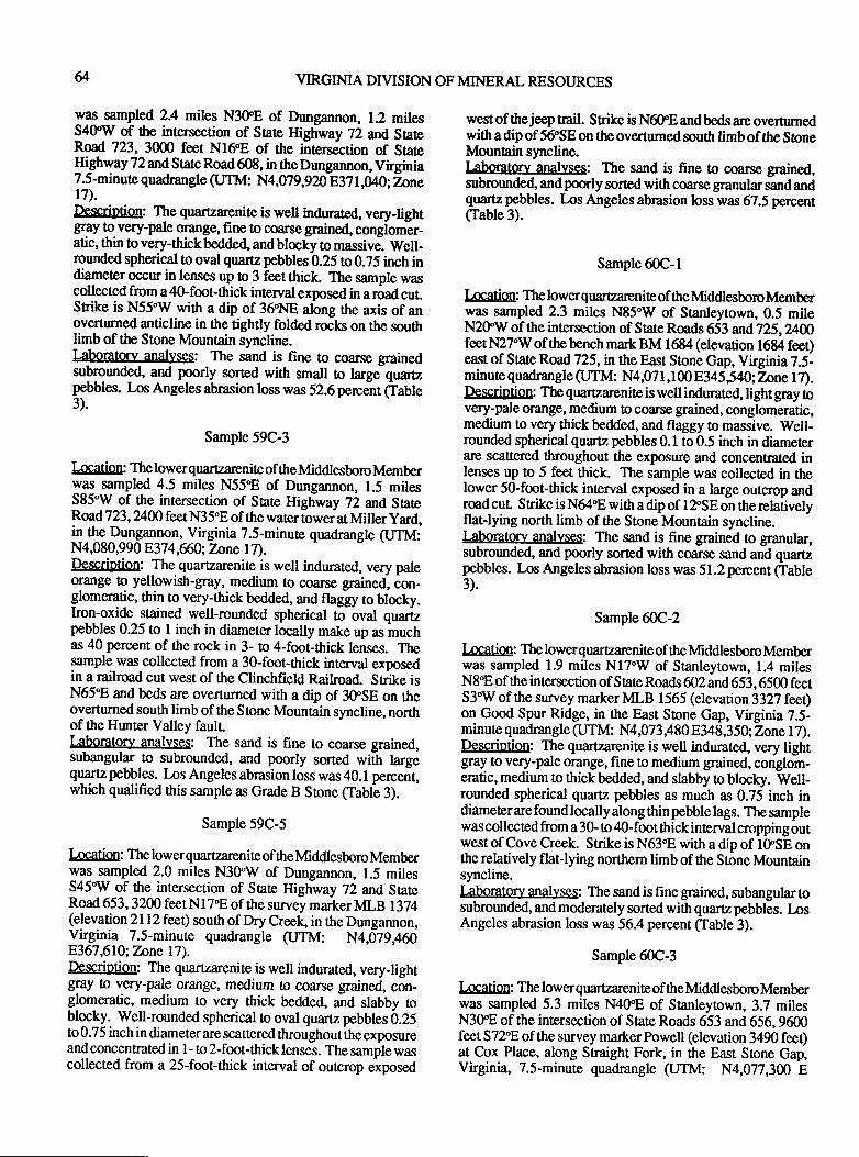
VIRGIMA DTVISION OF MINERAL RESOURCES
was sampled 2.4 miles N3trE of Dungannon, 1.2 milesS4fW of the intersecrion of Sate Highway 22 and SateR;oad 723,3000 feet Nf6'E of the intersection of SAteHi_ghway 72 and State Road 608, in the Dungannon, Virginia7.5-minute quadrangle (UTM: N4,079,920 E37 l,M};Znnel7).Description: The quarearenite is well indurated, very-lightBfV lo-very-pale orange, fine to coarse grained, conglomer-atic, thin to very-thick bedde4 and blocky to massive. Well-rounded spherical to oval quartz pebblas 0.25 to 0.75 inch indiameter occu in lenses up to 3 feet thick. The sample wascollected from a 40-foot-thick interval exposed in a road cut.Srike is N55.W with a dip of 36'NE along the axis of anovertumed anticline in the tightly folded rocls on the soutlrlimb of the Stone Mountain syncline.L4borato.ry. anallrses: The sand is fine to coarse grainedsubrounded, and poorly sorted with smail to large quarupebblas. Los Angeles abrasion loss was 52.6 percent (fable3).
Sample 59C-3
Location: The lowerquartzarenite of ttreMddlesboroMemberwas sampled 4.5 miles N55'E of Dungannon, 1.5 milesS85"W of the intersection of State Highway 72 and StateRcgid,723,2l00 feet N35.8 of the water tower at Miller yard,
il.4g Orygunlon, Virginia 7.5-minute quadrangle (UTM:N4080,990 837 4,60; Tnne t7).Description: The quartzarenite is well indurated, very paleorange to yellowish-gray, medium to coarse grained, ion-glomeratic, thin to very-thick bedded, and flaggy to blocky.Iron-oxide stained well-rounded spherical to oval quarizpebbles 0.25 to I inch in diameter locally make up as muchas 40 percent of the rock in 3- to 4-foot-ttrick lenses. Thegample was collected from a 3O-foot-thick interval exposedin a railroad cut west of the Clinchfreld Railroad. Strike isN65E and beds are overfiirned with a dip of 3OSE on theoverturned south limb of the Stone Mountain syncline, northof the Hunter Valley faulrl"Aboratery anal],ses: The sand is fine to coarse grained,subangular to subrounded, and poorly sorted with largequaru pebbles. los Angeles abrasion loss was 40.1 percent,which qualified this sample as Grade B Stone (Table 3).
Sample 59C-5
Location: The lower quartzarenite of ttre Middlesboro Memberwas sampled 2.0 miles N3OW of Dungannon, 1.5 milesS45'W of the intersection of State Highway 72 and SateRoad 653, 3200 feet Nl 7E of the survey marker MLB I 374(elevation 2112 fee$ south of Dry Creek, in the Dungannon,Virginia 7.5-minute quadrangle (UTM: N4,079,460E367,610; Tnne l7).Description: The quartzarenite is well indurated, very-lightgray b very-pale orange, medium to coarse grained, con-glomeratic, medium to very thick bedded, and slabby toblocky, Well-rounded spherical to oval quartz pebbles 0.25to 0.75 inch in diameter are scattered throughout the exposureand concentrated in 1- to 2-foot-thick lenses. The sampte wascollected from a 25-foot-thick interval of ourcrop e*posed
west of the jeep trail. Srike is N6OE andbeds arc overturnedwith a dip of 5ESE on the overturned south limb of the SoneMountain syncline.kboratc.v analyses: The sand is fine to coarse grained,subrounded, andpoorly sorted with coarse granular salrd andquartz pebbles. Ios Angeles abrasion loss was 67.5 percent(Table 3).
Sample 60C-1
[OCaliOU: Thelowerquaraarenite of the MddlesboroMemberwas sampled 2.3 miles N85'W of Stanleytown, 0.5 mileN2SWof the intersection of StaleRoads653 and725,24,Nfeet N27'W of the bench mark BM 16&4 (elevation 1684 fee$east of State Ro&725, in the East Stone Gap, Virginia 7.5-minute quadrangle (UTM: N4,07 l,lm E345 540;2one L7).Description: The quartzarenite is well indurated, light gray tovery-pale cange, medium o coarse grained, conglomeratic,medium to very thick bedded, and flaggy to massive. lVell-rounded spherical quartz pebbles 0.1 to 0.5 inch in diameterarc sca$ered throughout the exposure and concentrated inlenses up to 5 feet thick. The sample was collected in thelower S0-fmt-thick interval exposed in a large outcrop androad cul Srike is N64"8 with a dip of l2"SE on the relativelyftat-lying north limb of the Stone Mountain syncline.kboratorv anal]rses: The sand is fine grained to granular,subrounded, and poorly sorted with coarse sand and quartzpebbles. Los Angeles abrasion loss was 51.2 percent Cfable3).
Sample &C-2
Iaation: The lower quartzarenite of the Mddlesboro Memberwas sampled 1.9 miles N17"W of Stanleytown, 1.4 milesN8"E of the intersection of state Roads 602 and 653,6500 feetS3"W of the survey marker MLB 1565 (elevation 3327 feet)on Good Spur Ridge, in the East Stone Gap, Virginia 2.5-minute quadrangle (UTM: N4,073 380 8348,3 50; Zone 1 7).Description: The quartzarenite is well indurated, very lightgray to very-pale orange, fine to medium grained, conglom-eratic, medium lo thick bedded, and slabby to blocky. Well-rounded spherical quartz pebbles as much as 0.75 inch indiameterare foundlocally along thin pebble lags. The samplewas collected from a 30- to 40-foot thick interval cropping outwest of Cove Creek. Srike is N63.8 with a dip of IOSE onthe relatively flaflying northern limb of the Stone Mountainsyncline.I"aboratory anallrsqs: The sand is fine grained, subangular tosubrounded, and moderately sorted with quaru pebbles. LosAngeles abrasion loss was 56.4 percent (Table 3).
Sample 60C-3
Location: Thelowerquartzareniteof theMddlesboroMemberwas sampled 5.3 miles N4fE of Sranleytown, 3.7 milesN3fE of the intersection of State Roads 653 and 656,9600feet S72"E of the survey markerPowell (elevation 3490 feeDat Cox Place, along Straight Fork, in the East Stone Gap,Virginia, 7.5-minute quadrangle (JTM: N4,077,300 E
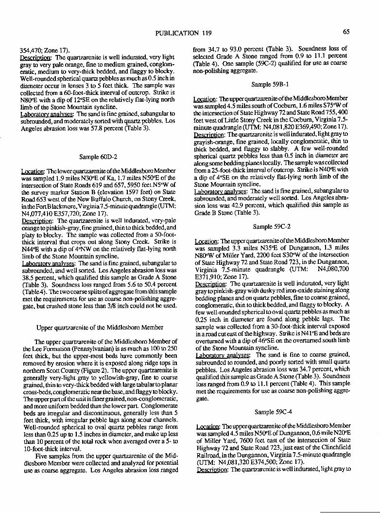
PUBLICATION 1T9 65
35aA70;ZonelT).Description: The quartzarenite is well indurated, very lightgray to very pale orange, fine to medium grained, conglom-eratic, medium to very-thick bedded, and flaggy to blocky.Well-rounded spherical quartz pebbles as much as 0.5 inch indiameter occur in lenses 3 to 5 feet thick. The sample was
collected from a 60-fmt-thick interval of outcrop. Stike is
N8OE with a dip of 12"SE on the relatively flat-lying northlimb of the Stone Mountain syncline.Laboratcy analyses: The sand is fine grained, subangular tosubrounded, and moderately sorted with quartz pebbles. LosAngeles abrasion loss was 57.8 percent (fable 3).
SamPle ffiD-2
I-ocation: The lowerquartzareniteof the Middlesboro Memberwas sampled 1.9 miles N3OE of Ka, 1.7 miles N5OE of theintersection of State Roads 619 and 657 ,5950 feet N5'W ofthe survey marker Station B (elevation 1597 feet) on StateRoad 653 west of the New Buffalo Church, on Stony Creek,in theFortBlaclrnore, Virginia?.5-minute quadrangle (UTM:N4,077,4 10 E357,720; Znne l7).Descrilltion: The quartzarenite is well indurated, very-paleorange to pinkish-gray, fine grained, thin to thick bedded, andplaty to blocky. The sample was collected from a 50-foot-thick interval that crops out along Stony Creek. Strike isN44'E with a dip of 4"NW on the relatively flat-lying northlimb of tte Stone Mountain syncline.Laboratorv analyses: The sand is fine grained, subangular !osubrounded, and well sorted. Los Angeles abrasion loss was38.5 percent, which qualified this sample as Grade A Stone(fable 3). Soundness loss ranged from 5.6 to 50.4 percent(Table4). Thetwocoarse splits of aggregate from this samplemet tlp requirements for use as coarse non-polishing aggre-gate, but crushed stone less than 3/8 inch could not be used.
Upper quartzarenite of the Middlesboro Member
The upper quartzarenile of the Middlesboro Member ofthe Lee Formation @ennsylvanian) is as much as 100 to 250feet thick, but the upper-most beds have commonly beenremoved by erosion where it is exposed along ridge tops innorthern Scott County (Frgure 2). The upper quartzarenite isgenerally very-light gray to yellowish-gray, fine to coarsegrained, thin to very-thick bedded with large tabular to planarcross-beds, conglomeratic near the base, and flaggy to blocky.The upperpartof the unitis finer grained, non-conglomeratic,and mors uniform bedded than the lower part. Conglomeratebeds are irregular and discontinuous, generally less than 5feet thick, with inegular pebble lags along scour channels.Well-rounded spherical to oval quartz pebbles range fromless than 0.25 up to 1.5 inches in diameter, and make up less
than l0 percent of ttre total rock when averaged over a 5- to1 0-foot-thick interval.
Five samples from the upper quaflzarenite of the Mid-dlesboro Member were collected and analyzed for potentialuse as coarse aggregate. Los Angeles abrasion loss ranged
from ?4.7 to 93.0 percent Clable 3). Soundness loss ofselected Grade A Sone ranged from 0.9 to 1l.l percent
(Table 4). One sample (59C-2) qualified for use as coarse
non-polishing agg! egate.
Sample 59B-l
l,ocation: The upperquartzarenite of the Middle.sboro Memberwas sampled 4.5 miles sqrth of Coeburn, 1 .6 miles S75"W ofttre intersection of State Highway 72 and State Road 755,400feet west of Linle Stony Creek in the Coeburn, Virginia ?.5-minute quadrangle (JTM: N4 ,08 I ,820 8369 A90;7nne 17) .
Description: The quartzarenite is well indurated, light gray tograyish-orange, fine grained, locally conglomeratic' thin tothick beded, and flaggy to slabby. A few well-roundedspherical quartz pebbles less than 0.5 inch in diameter are
along somebedding planes locally. The sample wascollectedft,oma 25-foot-thick interval of outcrop. Srike is N4fE witha dip of 4"SE on the relatively flat-lying north limb of the
Stone Mountain syncline.Laboratory analyses: The sand is fine grained, subangular 0o
subrounded, and moderately well sorted. Los Angeles abra-
sion loss was 42.9 percent, which qualified tltis sample as
Grade B Sone (Table 3).
Sample 59C-2
I-ocation: The upperquartzarenite of the Middlesboro Memberwas sampled 3.3 miles N35E of Dungannon, 1.3 milesN8OW of Milter Yud,2200 feet S3fW of the intersectionof State Highway T2andstate Road 723,inthe Dungannon,Virginia 7.5-minute quadrangle (UTM: N4,080,700E,371,910; Tnnel7).Descriotion: The quartzarenite is well indurated, very lightgmy topinkish-gray with dusky red iron-oxide staining along
bedding ptanes and on quartz pebbles, fine to coarse grained,
conglomeratic, thin to thickbedded, and flaggy to blocky. Afew well-rounded spherical to oval quartz pebbles as much as
0.25 inch in diameter are found along pebble lags. The
sample was collected from a 30-foot-thick interval exposedin a road cut east of the highway. Srike is N4 19E and beds are
overturned with a dip of 46"SE on the overturned south limbof the Stone Mountain syncline.Iaboratory anal]'ses: The sand is hne to coarse gtained,
subrounded to rounded, and poorly sorted with small quartz
pebbles. Los Angeles abrasion loss was 34.7 percent, whichqualified this sample as Grade A Stone (Table 3). Soundness
loss ranged from 0.9 to 11.1 percent (Table 4). This sample
met the requircments for use z$ coarse non-polishing aggre-gate.
Sample 59C-4
Location: The upperquartzarenite of the Middlesboro Memberwas sampled 4.5 miles N5OE of Dungannon, 0.6 mile N2098
of Miller Yard, 7600 feet east of the intersection of State
Highway 72 and State Road 723, just east of ttre ClinchfieldRailroad, in the Dungannon, Virginia 7.5-minute quadrangle
(UTM: N4081,320 8374,500; Tnne l7).Description: The quartzarenite is well indwated, light gray o
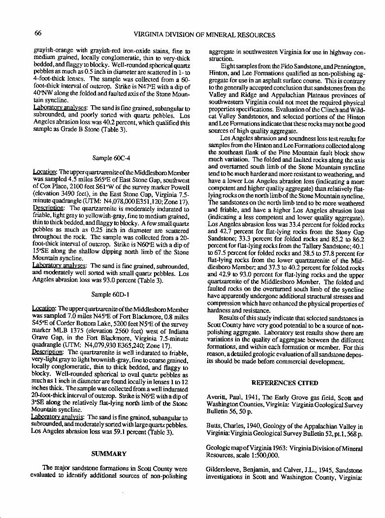
VIRGINIA DIVISION OF MINERAL RESOURCES
grayish-orange with grayish-red iron-oxide stains, fine [oledium grained, locally conglomeratic, thin to very-thickbedded, and flaggy to blocky. Well-rounded spherical quartzpebbles as much as 0.5 inch in diameter are scaaered in t- to4-foot-thick lenses. The sample was collected from a 60-foot-thick interval of outcrop. Strike is N47'E with a dip of4ffNW along the folded and faulted axis of ttre Stone Moun-tain syncline.I-Aborato.ry.anallrses: The sand is fine grained, subangular tosubrounded, and poorly sorted with quartz pebblei. LosAngeles abrasion loss was 40.2 percent, which qualified thissample as Grade B Srone (Table 3).
Sample 60C-4
lncation: The upperquartzarenite of ttre Mddlesboro Memberwas sampled 4.5 miles S65"E of East Stone Gap, southwestof Cox Place,2100 feet S61"W of the survey markerpowell(elevation 3490 feet), in the East Stone Gap, Virginia 7.5-minure quadrangle (JTM: N4,078,000 8351,120;hne l7).Dp$pdo$on: The quartzarenite is moderately indurated iofriable,_light gray to yellowish-gray, fine to medium grained,thin to thick bedded, and flaggy to blocky. A few small quartzpebbles as much as 0.25 inch in diame0er are scatteredthroughout the rock. The sample was collected from a 20-foot-thick interval of outcrop. Srike is N6OE with a dip of15'SE along the shallow dipping north limb of the StoneMountain syncline.Laboratory anal),ses: The sand is fine grained, subrounded,and moderately well sorted with small quartz pebbles. LosAngeles abrasion loss was 93.0 percent (Table 3).
Sample 60D-l
Iaation: The upperquartzareniteof the Middlesboro Memberwas sampled 7.0 miles N45"E of Fort Blackrnore,0.g milesS45t ofCorder Bouom lake,5200 feetN5E ofthe surveyqrarker MLB 1375 (elevation 2560 feet) west of IndianiGrave Gap, in the Fort Blackmore, Virginia 7.5-minutequadrangle (JTM: N4,079,930 8365,24A; Zone l7).Description: The quartzarenite is well indurated to friable,very--light gray to light brownish-gray, fine to coarse grained,
lfulty conglomeraric, thin n thick bedded, and fllggy toblocky. Well-rounded spherical to oval quartz pebUles asmuch as 1 inch in diameter are found locally in lenses I to 12inches thick. The sample was collected from a well indurated2O-foot-ttrick interval of ourcrop. Srike is N6"E with a dip of3"SE atong the relarively flat-lying norttr limb of the SloneMountain syncline.LAboratolv_analvsis: The sand is fine grained, subangular tosubrounded and moderately sorted with large quartz pelUtes.lns Angeles abrasion loss was 59.1 percent Gabb 3).
SUMMARY
- The lajor sandstone formations in Scotr County were
evaluated !o identify additional sources of non-polishing
aggegate in southwestern Virginia for use in highway con-stnrction.
Eight samples from the Fido Sandstone, andpennington,Hinton, and Lee Formations qualified as non-polishing ag-gegate for use in an asphalt surface course. This is contraryto the generally accepted conclusion that sandstones from theValley and Ridge and Appalachian Plateaus provinces ofsouthwestern Virginia could not meet the required physicalproperties specifications. Evaluation of the Clinch and Wild-cat Valley Sandstones, and selected portions of the Hintonand Lee Formations indicate that these rocks may not be goodsources of high quality aggegate.
Ins Angeles abrasion and soundness loss testresults forsamples from the Hinton and Lee Formations collected alongthe southeast flank of the Pine Mountain fault block showmuch variation. The folded and faulted rocks along the axisand overnrned south limb of the Stone Moun[ain synclinetend tobe much harderand moreresistant to weathering, andhave a lower Los Angeles abrasion loss (indicating a morecompetent and higher quality aggregate) than relatively flat-lying rocks on the north limb of the Stone Mountain syncline.The sandstones on the north limb tend to be more weatleredand friable, and have a higher lns Angeles abrasion loss(indicating a less competent and lower quality aggegate).Los Angeles abrasion loss was 33.4 percent for folded rocksand 42.7 percent for flat-lying rocks from the Sony GapSandstone; 33.3 percent for folded rocks and 85.2 n 86.1percent for flat-lying rocks from the Tallery Sandstone;40.1to 67 .5 percent for folded rocks and 38.5 !o 57.8 percent forflat-lying rocks from the lower quartzarenite of the Mid-dlesboro Member; and 37.3 w 40.2 percent for folded rocksafi 42.9 to 93.0 percent for flat-lying rocks and the upperquartzarenite of the Middlesboro Member. The folded andfaulted rocks on the overhrned south limb of the synclinehave apparently undergone additional sructural stresses andcompression which have enhanced the physical properties ofhardness and resistance.
Results of ttris study indicate that selected sandstones inScott County have very gmd potential to be a source of non-polishing aggegate. I:boratory test results show there arevariations in the quality of aggregate between the differentformations, and within each formation or member. For thisreason, adetailedgeologic evaluation of all sandstone depos-its should be made before commercial development.
REFERENCES CITED
Averi$, Paul, 1941, The Early Grove gas field, Scofi andWashington Counties, Virginia: Virginia Geological SurveyBulletin 56, 50 p.
Buus, Charles, 1940, Geology of the Appalachian Valley inVirginia:Viryinia Geological Survey Bulletin 52, pt.l, 568 p.
Geologic map of Virginia 1963: VirginiaDivision ofMineralResources, scale 1 :500,000.
Gildersleeve, Benjamin, and Calver, JL.,Ig4S, Sandstoneinvestigations in Scott and Washington County, Virginia:
PUBLICATION 119
Tennessee Valley Authority Open-File Report, ll p.
Ilarris, W.B. , 1972, High-silica resources of Clarke, Freder-ick, Page, Rockingham, Shenandoah, andWanen Counties,Virginia: Virginia Division of Mineral Resources MineralResources Report Il, 42 p.
Henika, W.S., 1988, Geology of the East Stone Gap quad-rangle, Virginia: Virginia Division of Mineral ResourcesPublication 79.
Koning, T.L., and Cavaroc, V.V., 1 989, Infl uence of geologicfactors on the abrasion of quartzitic aggregates: Unpublishedreport of the Department of Marine, Earth, and AtmosphericSciences, North Carolina State University, Raleigh, NorthCarolina,47 p.
McKee, E.D., and Weir, G.W., I 953, Terminology for srati-fication and cross-stratification in sedimentary rocks: Geological Society of America Bulletin, v. 64, p. 381-390.
Miller, R.L., Harris, L.D., and Roen, J.B., 1964, The WildcatValley Sandstone (Devonian) of southwest Virginia: in U.S.Geological Survey Professional Paper 501-8, p.B.49-B.52.
National Crushed Stone Associatton,1972, Flexible pave-ment design guide for highways, Washington, D.C.,40 p.
Nolde, J.E., and Diffenbach, R.N., 1988, Geology of theCoeburn quadrangle and coal-bearing portion of the Dungan-non quadrangle: Virginia Division of Mineral ResourcesPublication 81.
Sweet, P.C., 1981, High-silica resources in Augusta, Bath,Highland, and Rockbridge Counties, Virginia: VirginiaDivision of Mineral Resources Publication 32,22p.
Sweet, P.C., and Wilkes, G.P., 1 986, High-silica resources inAlleghany, Botetourt, Craig, and Roanoke Counties, Vir-ginia: Virginia Division of Mineral Resources Publication67,21p.
Sweet, P.C., 1986, Virginia's indusrial silica resources:Virginia Division of Mineral Resources Virginia Minerals, v.32,n.1,p.1-9.
Virginia Department of Transportation, 1987, Road andbridge specifications: Virginia DeparEnent of Transporta-tion, 721p.
Whitlock, W.W., Lovetl J.A., and Diffenbrch, RN., 1988,Geology of the Wise quadrangle and the coal-bearing portionof the Fort Blackmore quadrangle, Virginia Virginia Divi-sion of Mineral Resources Publication 80.
67

68 YIRGINIA DTVISION OF MINERAL RESOURCES
PUBLICATION II9
VIRGINIA CARBONATE ROCKS AND SAMPLING PROJECT
William W. WhitlockVirginia Division of Mineral Resources
P.O. Box 144Abingdon,VA242n
andWilliam F. Giannini
Virginia Division of Mineral ResourcesP.O. Box 3667
Charlottesvill e, Y A 22903
69
ABSTRACT
Virginia has abundantreserves of carbonaterocls. Lime-stones and dolostones fum a large portion of the surfaceformations in the Valley and Ridge province of Virginia.Minor occurrences of carbonate rocks are also found in thePiedmontprovince as limestoneand marbleand in the CoastalPlain province as shell deposits.
In 1987,52 quarries and 2 underground mines produced21,U2,600 short tons of carbonate material. Major uses forhigh-purity limestone supplied by Virginia operations in-clude lime to treat water and sewage, in the paper and steelindustries, and for agricultural use to stabilize soil and toenhance its fertility. Environmentally oriented markets in-clude use in control of sulfur and nitrogen emissions fromstacks of coal-fired boilers, and acid-conrol sone. Othermarkets utilizing high-purity carbonate-rock products in-clude cement-mortrar manufacture; glass and steel industries;and fillen and extenders such as in fertilizer, animal feed,wallboard joint compound, paint, rug backing, anti-stickagents, the manufacture of chemicals, and rubber. Majormarkets not requiring high-purity carbonate rocks include ag-gregate stone for concrete, asphalt, highway base mix, con-crete block, railroad ballasL soil-fertility enhancement, andfor coal-mine dust.
In 1981, the Virginia Division of Mineral Resources(VDMR) initiated a sampling project to determine chemistryand reflectance (brightness, tint, whiteness) values ofVirginia' s carbonate rocks. To date, 3 963 samples have beencollected and 3548 chemically analyzed. Of those analyzed,128 qualify as high-reflectance material. These results willbe published in a series of VDMR repors . These reports willform a database which will provide valuable information !oprivate individuals, companies, consuhants, and local andstate govemments.
INTRODUCTION
Virginia has abundantreserves of carbonaterocks. Theserocks range from the high-calcium New Market, Five Oaks,and Rockdell Limestones with as much as 98 percent calciumcarbonate (CaCO) to high-magnesian Shady Dolomite andHonakerFormation containing as much as 45 percent magne-sian carbonate (MgCO) and 53 percent CaCOr. As a result"Virginia's carbonate rocks have potential use for a variety of
chemical applications as well as aggregate, which isbased onphysical properties. During 1987-89, carbonate rocks valuedatapproximately $80 million per yearwere produced in Vir-ginia"
This paper focuses on the chemical compositions and
chemical uses of Virginia's carbonate rocks. The VirginiaDivision of Mineral Resources is conducting a study tosample, analyze,and inventory the chemical andreflectancecharacteristics of these rocks. Determination of the chemicalcomposiiion and reflectance values identifies formationssuitable for various uses. Several major uses are discussedbelow and several formations are described which meet therequirements for each use.
SAMPLING PROJECT
Between 1845 and 1981, approximately 700 carbonate-rock samples were collected in Virginia and analyzed forchemical composition. In 1981, the Virginia Division ofMineral Resources initiated a project 0o collect and analyze
samples for all carbonate-bearing formations of Virginia Todate, 3963 samples have been collected of which 3548
samples have been chemically analyzed for 10 elements, 147
have been tested for reflectance values, 152 for chlorinecontent, and 119 have been arnlyzeA for ftace elements.
PROCEDUREFOR SAMPLING
An acempt is made to obtain representative samples ofeach formation in an area. Chip samplas as much as 3 inches
in diameter are taken across continuous rock outcrops. Samples
are taken at s-foot intervals of true thickness on large out-crops, or closer when needed tn sample variations in thelithology. Formations are sampled at approximately l-mileintervals along srike. Across strike, samples may be taken atcloser intervals if folds or faults are present. Impurities such
as chert or shale are noted but not sampled.Sampling continues in an area until the geologist deter-
mines sample density is sufficient to give a reasonable repre-
sen0ation of each formation.Initial sampling for this project began in the northern
Valley and Ridge province of Virginia. Sampling will con-tinue to progress southwardby penonnel from the Charlot-tesvilleoffice. Sampling began in southwestVirginia in 1984
70 VIRGIMA DIVISION OF MINERAL RESOURCES
and will continue northward by a geologist from the Divisionof Mineral Resources' Abingdon field office.
Three publications in preparation will report results ofanalyses for l) northern Virginia (Winchester and Frederick0.5"x 1" quadrangles), (Giannini, in prep.,a), 2) north-centralVirgrnia @ront Royal and Washington West 0.5tr l. quad-rangles), (Giannini, in prep.,b), and 3) north-cenEal andcentral Virginia (Charlottesville and Fredericksburg 0.55r l0quadrangles), (Giannini, in prep.,c).
TESTING
Samples are tested in the Division of Mineral Resourceslaboratory in Charlottesville for l0 elements:
CaCO, MgCQ
qo Nqo
SiO2 F"P, NP,
Tio2 PrQ S
Samples are crushed until 95 percent passes the 325-mesh and then they are composited; 2 grams are mixed with2 grams of chromatographic cellulose and pressed into 1.25-inchpellets under 25 tons pressure. Pellets are analyzed usingaDiano XRD 700 wavelength dispersiveX-ray fluorescenceunit. A flow-proportional counter, coarse collimator, andpulse height discriminator are used for all analyses andcorrections are made for background levels, dead time, anddrift.
To test for reflectance, all samples collected are com-pared visually to a sample of the same mesh size which isknown !o reflect 70 percent brightness. Samples whichappear to have the same or greater brightness are tested usinga Photovolt Corporation reflectance spectrophotometer and amagnesian-carbonate primary standard. The sample is pul-veizrdto 325-mesh size andpressedinto a briquette. Bright-ness percent is determinedby reflecting agreen filtered lightfrom the briquette. Tint is determined by using brighrresspercent minus the percent reflection through a blue filter, andwhiteness percent is derived by calculations as follows:
Brightness - (Tint X 4) = Whireness
The testing procedure was adapted from the "Method ofTest 5-68T, Determination of Dry Brightrress of GroundLimestore", @ulverized Limestone Association, 1984). Toda0e, 147 samples have qualified as high reflectance material.
CHEMICAL USES
High-purity limestone and dolostone have a variety ofuses including: limeproduction and lime fo treat waterandsewage, use in the paper and steel industries, and agriculturaluse to stabilize soil and to enhance its fertility. Environmen-tally oriented markets include use in control of sulfur andnitrogen emissions from stacks of coal-fired boilers and foracid-control stone. Ofter markets utilizing high-purity car-bonate-rock include fillers and extenders used in fertilizer,animal feed, wallboard joint compound, paint, rug backing,
anti-stick agents, the manufacture of chemicals, and rubber.Five of the highest demand chemical uses are discussed
below. These uses include: l)treating water and sewage,2)chemical and metallurgical uses, 3)agricultural limestone,4)fillers and extenders, and 5) control of sulfur emissionsfrom stacks of coal-fired boilers.
WATER AND SEWAGE
The main function of limestone in this category is as thesource of quicklime (CaO) or hydrated lime (Ca(OH)r).Treating water and sewage is a major use of lime @oynton,1980; Sweet, 1986).
In water treatrnent, lime is introduced to improve thewater quality in several ways. Adding lime will raise the pHlevel, resulting in reduction of bacteria. At the same time thelime will reduce bicarbonate in the water. Lime will alsoreduce the suspended solids and turbidity in water. Industrieswhich require large volumes of water use lime to allow thewater to be recycled.
Lime is used in sewage treatrnent to elevate pH levels.This results in precipitation of phosphorian and nitiancompounds and destruction of pathogens.
Generally a high-calcium limestone with 95 percent orgrcater CaCO, is required for the manufacture of lime forthese applications.
C}IEMICAL AND METALLURGICAL USES
Limestone and dolostone and the calcined forms of bothhave a variety of chemical and metallurgical uses. Theirapplication in the production of glass, paper, or steel aregeneral examples of how the carbonate rocks are used in thiscategory.
High-calcium limestone, high-magnesian doloslone, andlimeare used in the manufacture of glass. These malerials actas a flux and also make the glass less brittle. Glass made withdolostone has enhanced resistance to quick temperaturechanges. Chemical requirements for the rock or lime mayvary slightly with each producer; however, high-quality glassgenerally requires 98 percent or greater CaCO" for limestoneand 98 percent or greater CaCO. + MgCO" ior dolostone.Also Fepr generally must be lesi than 0.0ipercent"
Lime is used in the paper industry in several ways. It iscombined with chlorine gas to form-a stable bleach. firisproduct is then combined with the pulp to bleach the paper. Inaddition,lime is mixed with sodium carbonate which is awaste product of the paper-making process. It reacts formingsodium hydroxide which can then be reused. Chemicalrequirements dicate that the limestone source for the lime has95 percent or grcater CaCO".
Limestone, dolos0one, dnd time are used as flux in mostmetallurgical processes. The rock u lime react with the ore!o flux out (seprale) impurities such as silica, alumin4manganese, phosphorous, or sulfur (Boynlon, 1980). Lime-soorp mustcontainaminimum 95 percent CaCQand dolos-tone should contain a minimum of 95 percenf combinedCaCOr+ MgCQfor use as a metallurgical flux. Impurities
PUBLICATION 119 71
such as SiOrwill reduce the ability of the lime to react withimpurities in the ore, and therefore should be minimal.
AGRICULTURAL LIMESTONE
Agricultural lime is a general term which can actuallyrefer to pulverized limestone, dolostone or calcined andhydrated lime. The material is spread over soil to regulate theacidity and to introduce the plant nutrients Ca and Mg into thesoil. Dolostone actually has a higher acid neutralizing valueper unit of weight than limestone.
Virginia state regulations require limestone or dolostoneto have a calcium carbonate equivalent [CCE= VoCaCOr+(1.19 x ToMgCO)l of 85 percent or greater to be utilized forsoil enhancemenl Calcined lime must have a CCE of 140percent and hydrated lime a CCB of 110 percent (Va. Deptof Agri. and Consumer Services, 1986).
FILLERS ANDEXTENDERS
Calcium carbonate has many uses as an industrial filleror extender. It increases body or bulk which reduces costs inmaking rubber, it adds whiteness and opacity to paint, and isused for loading (filling the voids of paper fiber) and coatingpaper. In these uses the physical characteristic, brightness, isa main consideration, although limestone used in rubbergenerally requires 98 percent CaCO, content. Often, ttrespecific requirements vary from oneuser to another, but thereare industry-wide minimum standards (Boynton, 1980).Generally, a minimum brighrness value of 70 percent isrequired for a material to be considered for use as a filler orextender.
Calcium carbonateis generallyprefenedover lime (CaO)
because the calcium carbonate is more inert to other chemi-cals in the mixture. The form of the CaCO3 may varydepending on its use; however, it generally is produced aspulverized limestone, whiting (finer, more intensely gtoundlimestone), and precipitated calcium carbonate (produced bychemical processes which result in a uniform, micro-fine,white material).
CONTROL OF SULFUR EMISSIONS
The use of limestone to reduce emission from the stacksof coal-fired plants came into existence with the passage ofclean air legislation of the mid-1970's. New clean airlegislation, if enacted, will increase demand for limestoneusage as sulfur dioxide(SOr) emissions are resricted to 1980levels. Five proposed coal-fired power plants to be built inVirginia will require an additional 300,000 ons of limestoneannually to reduce SOremissions (personal communication,Alex Glover, 1990).
Two basic methods, scrubbers (or flue-gas desulfuriza-tion) and fluidized bed combustors, may use limestone toreduce SO, emissions.
In the scrubber method the exhausted gas is sprayed witha limestone medium above the zone of firing. Through a
series of chemical reactions, the SOrcombines with the Ca inthe limesone to form CaSQ.
In the fluidized bed combustor method, limestone and
coal are inroduced onto an air distribution grid in ttre fuingzone. Air forced through the grid creates a suspended bed.
Initially oil is introduced into the system to facilitate ignition.After ignition, crushed limestone and coal are continuouslyfed into the system. The limestone is calcined to CaO, reacts
with the SOrliberated from ttre coal, and forms CaSQ(Sweetand others, 1987).
Experimentation continues on new types of scrubbers
and fluidized bed systems. Also, experimencation continues
as to the best type of carbonate rocks to use in these methods'
Generally the requirements for limestone composition are a
mini{num 90 percent CaCO, and a maximum 5 percent
MgCO, In addition o chemical requirements, other rockproperties such as permeability are factors in the utilization oflimestone in flue gas desulfurization. In 1987, the Divisionof Mineral Resources conducted a preliminary study of 15
samples from selected quarries and pits in Virginia to deter-mine suitability of selected limestone formations. The NewMarket Limestone shows greatest potential for this use.
GEOLOGY
Most of the carbonate rocks in the state occur as lime-stone and dolostone in the Valley and Ridge province ofwestern Virginia. They crop out in long northeast- to sbuth-west-trending valleys between sandstone or siltstone cappedridges. Thebeds havebeen folded and faulted andrange fromflat-lying to vertical and overturned. The limestone and
dolostone formations are Cambrian o Mississippian in age
with a few, thin limestones of Pennsylvanian age. Potentialcommercial quantities of high-calcium limestone resources
are restricted to Middle andUpper Ordovician agerocks and
high-magnesian dolostone reserves are restricted to Cam-brian and Ordovician age rocks. In addition to the limestones
and dolostones, small Quaternary travertine-marl deposisare present in ttre Valley and Ridge province.
Minor amounts of carbonate-rock resowces are in cen-
tral and eastem Virginia. hecambrian-age marbles and Tri-assic limestone and dolostone conglomerates are in thePied-mont province. Tertiary age shell-marl deposits are present
in the Coastal Plain.Several formations that have the greatest economic po-
tential based on purity of rocks and extent of available re-
sources include: the New Market, Five Oa}s, and RockdellLimestones and the Shady Dolomite and Honaker Formation(Figure 1). These formations are described below.
NEW MARKET LIMESTONE
The Middle Ordovician New Market Limestone is in the
northern Valley and Ridge province of Virginia. It uncon-formably overlies the Beeknantown Formation or RockdaleRun Formation of ttre Beekmantown Group and is conforma-bly overlain by the Lincolnshire Limesone @gure l). The
New Market is as much as 300 feet thick in Rockingham
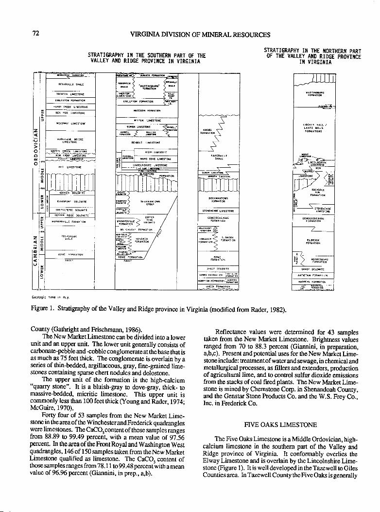
72 VIRGIMA DIVISION OF MINERAL RESOT.JRCES
STRATIGRAPHY III THE SOUTHERI{ PART OF THEVALLEY AI{D RIDGE PROVII{CE II{ VIRGII{IA
z
9ooEo
lsllolo
l=r"i]lot-
F€EDSVILLE SXAIE \EEair^Rrti$uR6- ( IrlrERTArcf,
\ sllr< ir'TRENTM LHESTOXE
TESTOXE
E@ESTON mRilArrOX €GLESrd FoRrAiox <*iIffARd CiE€X LIM€STONE
x@srr rciuAnot!EI HUR LIMESfON€
fIMESTOTE*[E{ UTESTOtE
a\
r|oSs s..
.\*__5
"^:ill!..,
____s___s-
ws LTMESUE <qdl!
LIXESTONE
> r^rrorrorrtor >
6€ta&r LrxEstoxE
TARTIN CRE€K IISESTON€ --t EEd UESFI'
i;
waiD @v€ LrMEsTot€
DOT LITESTONE
llt I T.-!|tL i
MAscor dolofrrE
BEEXMANTOIN /GR@P //
(INGSPORI DOLOHITE
CHEPULTEE @SMIII STNEA€NGE LITESiON€
zaao
=
l
o
=
to
coPPaR R|oGE 0oLot[E
,.;lil",li*. < -13fii* /CONOCOCNEAGUE
MAfrAMVILLE FOfiMATIO{
NOLICHUCKY FORHAiIOX
vil-id-h <nouE roRMATroN /
enrN roauarror illt-r.EJli
nxrro romrnor iglllfl
Geolo0ic limc in h.t.
Figure l. Snatigraphy of ttre Valley and Ridge province in Virginia (modified from Rader, 1982).
STRATIGRAPHY III THE I{ORTHERI{ PARTOF THE VALLEY AIID RIDGE PROVIIICE
II{ VIRGIIIIA
Reflectance values were detennined for 43 samplestaken from the New Market Limestone. Brightness valuesranged from 70 to 88.3 percent (Giannini, in preparation,a,b,c). Present and potential uses for ttre New Market Lime-stone include: treatmentof waterand sewage, in chemical andmetallurgical processes, as fillers and extenders, productionof agricultrual lime, and to control sulfur dioxide emissionsfrom the stacks of coal flred plants. The New lvlarket Lime-stone is mined by Chemstone Corp. in Shenandoah County,and the Genstar Sone hoducts Co. and the W.S. Frey Co.,Inc. in Frederick Co.
FIVE OAKS LIMESTONE
The Five Oaks Limestone is a Middle Ordovician, high-calcium limestone in the southern part of the Valley andRidge province of Virginia. It conformably overlies theElway Limestone and is overlain by the Lincolnshire Lime-stone (Figure 1). It is well developed in the Tazewell to GilesCounties area. In Tazewell County the Five Oaks is generally
County (Gathright and Frischmann, 1986).The New lvlarket Limestone can be divided into a lower
unit and an upper unit. The lower unit generally consists ofcarbonat€-pebble and +obble conglomerate at the base that isas much as 75 feet thick. The conglomerate is overlain by aseries of thin-bedded, argillaceous, gray, fine-grained lime-stones containing sparse chert nodules and dolostone.
The upper unit of the formation is the high-calcium"quarry stone". It is a bluish-gay to dove-gray, thick- tomassive-bedded, micritic limestone. This upper unit iscommonly less than 100 feet thick (Young and Rader,l974;McGuire,1970).
Forty four of 53 samples from the New Market Lime-stone in the area of the Winchester and Frederick quadrangleswere limestones. The CaCOrcontent of those samples rangesfrom 88.89 to 99.49 percedt, with a mean value of 9?.56porcent. In tre area of the Front Royal and Washington Westquadrangles, 146 of 150 samples taken from theNew MarketLimestone qualified as limestone. The CaCOa content ofthose samples ranges from 78.1 I to 99.48 percent-with a meanvalue of 96.96 percent (Giannini, in prep., a,b).
LIOERiY iAlI /LAtlz ttLls
PUBLICATION 119 73
less than 45 fee,t thick, although in one place in northernTazewell County it measured 1 17 feet thick In Giles Countythe Five Oaks Limeslone is as much as 130 feet thick. AtKimballon, Giles County, the upper 40-65 feet is high+al-cium limestone (Cooper, 1944).
The Five Oaks Limestone is equivalent to the Newlvlarket Limesone of the northern part of the Valley andRidge province in Virginia. The Five Oaks is generally mic-ritic to fine-grained, dove-gray to dark-gray limestone be-coming more argillaceous to the south and conaining occa-sional chert zones. Thirteen samples taken in Russell, Taze-well, and Gile,s Counties, contained 93.8 to 98.37 percent
CaCO" (Cooper, 1944, 1945). Cunent and potential uses forthe Five Oaks Limestone include: production of quicklimeand hydrated lime for water and sewage treatment, produc-tion of agricultural lime, use in chemical and metallurgicalprocesses, and use in the control of sulfur emissions from thestacks of cml fired plants. The Five Oaks Limestone is minedin Giles County by APG Lime Corp. and Virginia Lime Co.
ROCKDELLLIMESTONE
The Upper Ordovician Rockdell Limesone is present inScott and Russell Counties and the southern part of TazewellCounty. To the north it is called the Ward Cove and PeeryLimeslones. The Rockdell conformably overlies the Lin-colnshire Limestone and is overlain by the Benbolt Lime-stone (Figure l).
The formation ranges from 85-300 feet in thickness andis comprised of several rock types. In some areas theRockdell is mostly pure high-calcium limestone, in others itis interbedded with dark-bluish-gray limestone or dark-gray,granular, cherty limestone. The high-calcium part is gener-ally light gray o pinkish gray with a coarse-grained texture.Thirty one samples from Russell and Scott Counties have aCaCO" content of 94.5 to 98.28 percent (Cmper, 1%5).Chemical values indicate the Rockdell Limestone could beused in chemical and metallurgical processes, water and sew-age treafnent, production of agficultural lime, and control ofsulfur dioxide emissions from the stacks of coal fired planrs.The Rockdell Limesone was recently mined at Speers Ferryin Scott County.
SHADY DOLOMITE
The Lower Cambrian Shady (fomstown) Dolomiteextends the entire lenglh of the Valley and Ridge province inVirginiaalong thebaseof ttre westem limb of the BlueRidgeMountains. It is the oldest carbonate-bearing formation inthat area, overlying lower Cambrian sandstones of the Erwinand Antietam Formations and overlain by red and green
shale, sandstone, dolos3one, and limestone of the Rome andWaynesboro Formations (Figure 1). The Shady Dolomitegenerally averages 1800 feet thickness except for an anomal-ously ttrick section (50CI fee$ near Austinville in WytheCounty.
The Shady Dolomite is predominantly a high-magnesian
unit that is generally fine- to medium-grained, very thick- to
massive-bedded, bluish gray to gray and buff to white. Insome areas itcontains zones of dark-gray oblack, very-fine-grained, thin-bedded limesone @utts, 1940)l
Fifteen of 18 samples takenin theareaof theWinchesterand Frederick quadrangles, were dolostone with 42.Y lo45.11 percent MgCOrand 51.35 to 56.69 percent CaCQ. 11
the Front Royal and -Washingon
West quadrangles, 5 of 6samples were dolostone with 39.98 n 4.63 percent MgCO,and 50.23 to 53.56 percent CaCO, . Reflectrnce values for 6samples taken in the area of the Winchester and Frederickquadrangtes range from 70.3 to 83.3 percent brightness(Giannini, in prep, a,b). Cunent and potential use.s of the
Shady Dolomite include: chemical and metallurgical proc-
esses, production ofagricultural limeslone, and in fillers and
exrcnders. The Shady Dolomite is being mined in Clarke,Boteourt" and Wythe Counties and the City of Roanoke.
HONAKER FORMATION
The Middle Cambrian Honaker Formation crops out inthe southem Valley and Ridge province of Virginia. Itoverlies shale, sandstone, limestone, and dolostone of theRomeFormation and is cappedby shale and dolostone of fteNolichucky Formation. In the exEeme southwest the Ho-naker Formation grades into the Rutledge Limestone, Ro-gersville Shale, and Maryville Limestone. To the northeast
it gradas into the Elbrook Dolomite (Figure 1).
The Honaker Formation averages 130G1400 feet inthickness. It is finely-granular, dark-bluish-gray dolostonewith zones of light- to brownish-gray dolostone (Cooper,1945). Twenty seven of 34 samples taken in WashingonCounty qualify as dolostone with 31.32 to 45.05 percent
MqCO. and 41.96 to 58.97 percent CaCO.. Seventeen of 2lsailple,i taken in Russell and Tazewell Cbunties qualify as
dolostone with 37.08 tD 45.94 percent MgCOrand 52.77 to57.76 percent CaCOr. Present and potential uses for the
Honaker Formation include: chemical and metallurgicalprocesses, fillen and exlenders, and agricultural lime. It isquarried in Washington, Scott, and Russell Counties.
REFERENCES CITED
Boynton,R.S., 1980, Chemistry and technology of lime and
limestone: New York, John Wiley and Sons,Inc., 578 p.
Buus, Charles, 1940, Geology of the Appalachian Valley inVirginia: Virginia Geological Survey Bulletin 52, Part I, 586p.
Cooper, B.N., 1944, Industrial limestones and dolomites inVirginia: New River-Roanoke River Districu Virginia Geological Survey Bulletin 62,98 P.
Cooper, B.N., 1945,Industrial limestones and dolomites inVirginia: Clinch River Districc Virginia Geological SurveyBulletin 66,259p.
VIRGINIA DIVISION OF MINERAL RESOURCES
Gathright, T.M., II, and Frischmann, p.S., 19g6, Geology of$9 t{qnisonburg and Bridgewater quadrangles, Virginia:Virginia Division of Mineral Resources publication 60, 2t p.
Giannini, W.F., in preparation, a, Analyses of carbonaterocks- northern Virginia: Virginia Division of Mineral Re-sources Publication.
Giannini, W.F., in preparation, b, Analyses of carbonaterocks- north-central Virginia: Virginia Division of MineralResources Publication.
Giannini, W-F., in preparation, c, Analyses of carbonaterocks- north-central and central Virginia: Virginia Divisionof Mineral Resources Publication.
McGuire, O.S., 1970, Geology of the Eagle Rock, Strom,9t-*-y, and Salisbury quadrangles, Virginia: Virginia Di-vision of Mineral Resourses Report of Investigation2, 39 p.
Pulverized Limestone Association, I 984, Determination ofdry brighrress of ground limestone: Method 5,68T, p. 19-21.
Rader, 8.K., 1982, Valley and Ridge stratigraphic correla-tions, Virginia: Virginia Division of Min-eral ResourcesPublication 37, chm.
Swee! P.C., 1986, Virginia's lime industry: Virginia Divi-sion of Mineral Resources Virginia Minerali,v.32,n.4,p. 33-43.
l*""t, P.C., Fordham, O.M., Jr., and Giannini, W.F., 19g?,Carbonate materials suitable for desulfurization of flue gas:Virginia Division of Mineral Resources Virginia Mineils,v.33,n.4,p.33-36.
Virginia Department of Agricultrue and Consumer Services,1986, Virginia Agricultural Liming ldaterials Law, 5 p.
Young, R.S., and Rader, 8.K., 1974, Geology of the Wood-stock, Wolf Gap, Conicville, and Edinburg quadrangles, Vir-ginia: Virginia Division of Mineral Resources Report of In-vestigation 35, 69 p.
PUBLICATION II9
BRICK PRODUCTION, COMBINING ART WITH SCIENCE
Iron F. Williams,ItrBrick and Tile Corporation of Lawrenceville
P.O. Box 45Lawrenceville, Virginia 23 868
75
Brick production involves the processing of clay andshale into abuilding material thatisboth durable and aestheti-callypleasing in form. AtBrickandTile Corporation, apartlyweathered schist and a highly weathered shale and clayresiduum are used to produce brick.
Our pnocess starts at the mine site. Successful operationand production of high quality products requires that depositsbe located and tested far in advance of actual use. Wecurrently have enough proven reserves to operate at fullcapacity until the year 2010.
The schist materialwe useis afairly hard depositthathasbeen formed under a $eat deal of heat and pressure. Weutilize a Cat D-8 ripper to loosen up this material and use pansto transport it to stockpiles of up to 100,000 cubic yards. Wemine the material in "benches" to blend the material bothvertically and horizontally. This material gets progpssivelyharder as we mine deeper. We occasionally encounter somequartz veins in this deposit as well as some sericite. Theseaffect the finished color and are not desirable. We rip up theexposed part of the deposit in the fall and allow the freeze-thaw action in the winter to weather this portion of thematerial. We can then mine this material, to depths of 30 feet"and place it in stockpiles.
The weathered shale and clay rcsiduum deposit is ap-proximately l0 miles east of the schist deposit at the pointwhere the foothills andcoastal plain meet This shale is fairlysoft and layered with a great deal of weathered residuum. Wealso use the D-8 ripper on this material and pans to transportitto stockpiles. Wealso mine this material in "benches" forblending purposes. The material is placed in thin layers,which allows a mixture of matedal from different elevationsand areas within the pit and results in uniform properties. Wehave !o be very careful about blending in order to provide auniform raw mat€rial. These piles are approximately 12-15feet in height and contain from 50,000 !o 100,000 cubic yards.
These materials, which are hauled into the plant andstored separately, are currently used in a l:1 ratio. Approxi-mately 480 tons of material per day, 5 days per/week areground in hammermills and screened through 6 12 meshscr@ns.
The next step in the process is the forming of the brick.We extrude our brick on npo exrusion lines. Tln ground mixis de-aired in a chamber over the augers before extrusion. Anabsolute pressure of 2 inches s about 28 inches of vacuum ismaintained. This densifies the bnick and provides a betterquality producl The material is extruded in a continuouscolumn by the augers. A bridge inside of the die forms thecse holes continuously. These dies can be made to extrudea variety of shapes. The augers in tlre machine send twocontinuous ribbons of clay through the die which must knitbrck together. Occasionally on some solidbrick we may seea small surface defect, which means there are severe lamina-
tions inside. We try to make our brick as free of laminationsas possible; however the nature ofthe process is that there arealways lamination layers even if you cannot see them. Strangethings can also happen if impurities such as carbon get intoourmaterial. Carbon mustbe oxidizedcarefully during firingfor removal or bloating and black coring will occur.
After the brick are extruded they are cut either by realcutters orbypush-through cutters and setonkiln carsby hand
or machine. During this forming and setting part of theprocess we must carefully warch the green strength of ourware. This is done by occasionally checking the breakingstrength of these green brick. This concern with green
sfiength also requires us to run checks on the particle sizedisribution of our groundraw material mix. We also vary themix on small test runs to monior the properties resulting fromthe various combinations.
People tend o concen8ate their interest on the firing partof the process after they leave the forming area; however, thedrying process may be and in fact with us is the more criticalarea in terms of potential losses. These older plants requireabout 5200 BTU's to dry and fire each single brick. Thedrying portion requires about 3,100 BTU's or about 607o ofttre total input. The temperature and humidity conditionsunder which we dry the brick are very critical. We must firstrun the brick through a predryer that is supplied by heat fromthe cooling end of the kiln. This energy is applied indirectlyto achieve drying at a gradual rate.
The brick leave this area after about Z hours. They enter
a dryer at about I l0 degrees F, and 28 hours later they leave
dry at 525 de,grees F. They then enter the kiln and are heatedto about 2000 degrees F. and are then cooled ro about 150
degrees F. in 30 hours. We have taken a brick with 20Vo
moisture as 80 degees F. dried it, heated it to 2000 degreas
and cooled it in about 82 hours. They are then either hand
unloaded and gnded or unloaded by nnchine.There is also interest in brick sculpturing wall size
murals today. These mustbe carefully hand craftedby artistsand given special care in every step of the drying and fhingprocess !o achieve the desired product
The end result of all of this is a building which has adistinctive appearance with durability and low maintenance.

76 VIRGINIA DTVTSION OF MINERAL RESOI]RCES
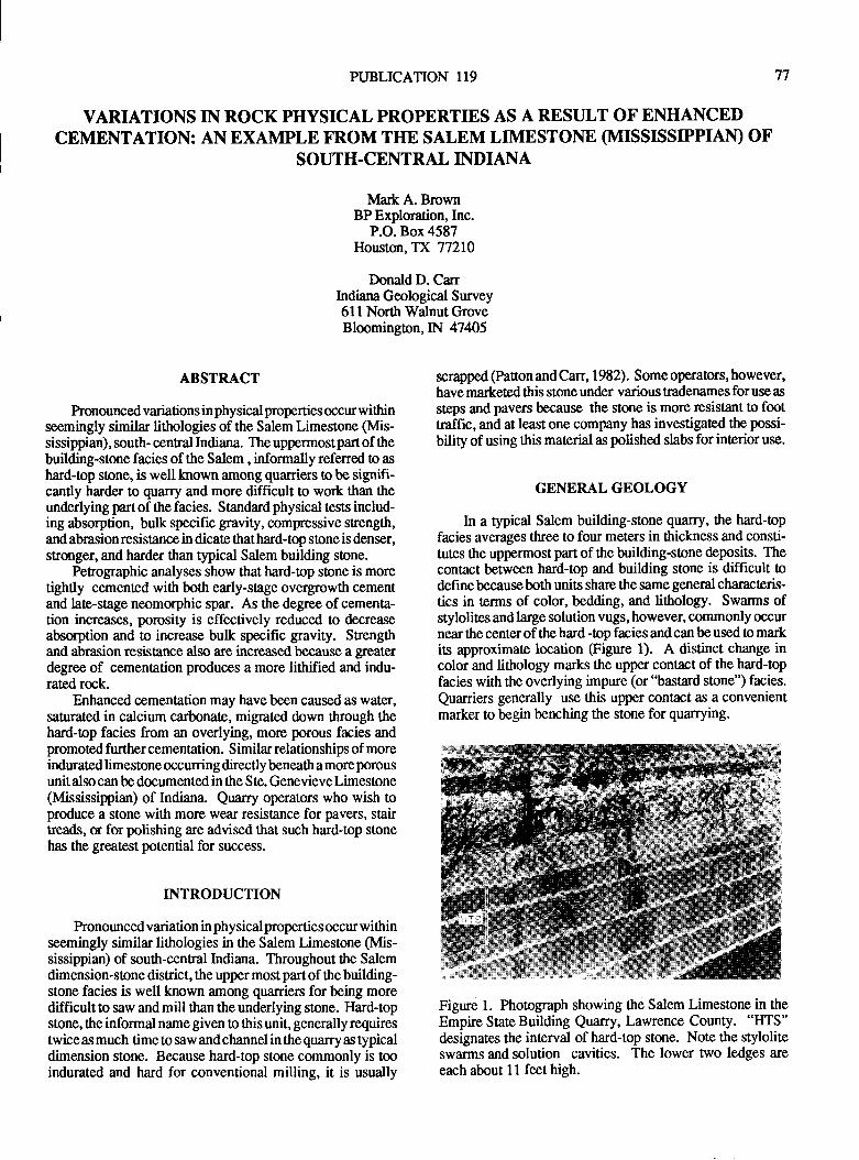
PUBLICATION 119 77
VARIATIONS IN ROCK PHYSICAL PROPERTIES AS A RESULT OF ENHANCEDCEMENTATION: AN EXAMPLE FROM THE SALEM LIMESTONE (MISS$SIPPIAN) OF
SOUTH-CENTRAL INDIANA
lvlaft A. BrownBP Exploration, Inc.
P.O. Box 4587Houston, TX 77210
Donald D. CarrIndiana Geological Survey6ll North Walnut GroveBloomingon,IN 47405
ABSTRACT
Pronounced variations in physical properties occur withinseemingly similar lithologies of the Salem Limestone (Mis-sissippian), south- cenral Indiana. The uppermostpartof thebuilding-stone facies of the Salem , informally referred to as
hard-op stone, is well tnown among quarriers to be signifi-cantly harder to quarry and more difficult to work than theunderlying part of the facies. Smndard physical tests includ-ing absorption, bulk specific gravity, compressive strength,and abrasion resistance in dicate that hard-top stone is denser,stronger, and harder than typical Salem building stone.
Petographic analyses show that hard-top stone is moretightly cemented with both early-stage overgrowth cementand late-stage neomorphic spar. As the degree of cementa-tion increases, porosity is effectively reduced to decreaseabso,rption and to increase bulk specific gravity. Strengtlrand abrasion resistance also are increased because a greaterdegree of cementation produces a more lithified and indu-rated rock.
Enhanced cementation may have been caused as water,saftrated in calcium carbonate, migrated down through thehard-top facies from an overlying, more porous facies andpromoted further cementation. Similar relationships of moreindurated limestone occurring directly beneath a more porousunit also can be documented in the Ste. Genevieve Limestone(Mississippian) of Indiana. Quarry operators who wish toproduce a stone with more wear resistance for pavers, stairheads, u for polishing are advised that such hard-top stonehas the geatest potential for success.
INTRODUCTION
Pronounced variation in physicalproperties occur withinseemingly similar lithologies in the Salem Limestone (Mis-sissippian) of south-cenral Indiana. Throughout the Salemdimension-stone district, the upper most part of the building-stone facies is well known :rmong quarrien for being moredifficult to saw and mill than the underlying stone. Ilard+opstone, the informal name given to this unit, generally requirestwice as much time to saw and channel in the quarry as typicaldimension stone. Because hard-top stone commonly is tooindurated and hard for conventional milling, it is usually
scrapped (Pafton and Carr, 1982). Some operators, however,have marketed this stone under various tradenames for use as
steps and pavers because the stone is more resistant to foottraffic, and at least one company has investigated the possi-
bility of using this material as polished slabs for interior use.
GENERAL GEOLOGY
In a typical Salem building-stone quarry, the hard-topfacies averages tlree to four meters in $rickness and consti-tutes the uppermost part of the building-stone deposirs. Thecontact between hard-top and building stone is difficult todefine becauseboth units share the same general charrcteris-tics in terms of color, bedding, and lithology. Swarms ofstylolites and large solution vugs, however, commonly occurnear the center of the hard -top facies and can be used to markits approximate location (Figure 1). A distinct change incolor and lithology marks the upper contact of the hard+opfacies with the overlying impwe (or "bastard stone") facies.
Quarriers generally use this upper contact as a convenientmarker to begin benching the stone for quarrying.
Figure 1. Photograph showing the Salem Limestone in theEmpire StateBuilding Quarry, tawrence County. "HTS"designates the interval of hard+op stone. Note the styloliteswarms and solution cavities. The lower two ledges are
each about 11 feethigh.
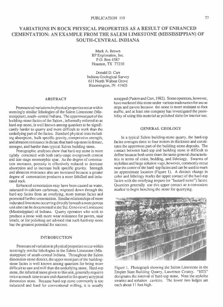
PUBLICATION 119 77
VARIATIONS IN ROCK PHYSICAL PROPERTIES AS A RESULT OF ENHANCEDCEMENTATION: AN EXAMPLE FROM THE SALEM LIMESTONE (MISS$SIPPIAN) OF
SOUTH.CENTRAL INDIANA
Ma* A. BrownBP Exploration, Inc.
P.O. Box 4587Houston, TX 77210
Donald D. CarrIndiana Geological Survey6ll North Walnut GroveBloomington,IN 47405
ABSTRACT
Pronounced variations inphysicalproperties occurwithinseemingly similar lithologies of the Salem Limestone (Mis-sissippian) , south- central Indiana. The uppermost part of thebuilding-stone facies of the Salem , informally referred to as
hard-op stone, is well known among quarriers o be signifi-cantly harder !o quarry and more difficult to work than theunderlying part of the facies. Standard physical tests includ-ing absorption, bulk specific gravity, compressive strength,andabrasionresislance in dicate thathard-top stone is denser,stronger, and harder than typical Salem building stone.
Penographic analyses show that hard-top stone is moretightly cemented with both early-stage overgrowth cementand late-stage neomorphic spar. As the degree of cementa-tion increases, porosity is effectively reduced to decreaseabsorption and to increase bulk specific gravity. Srengtlrand abrasion resistance also are increased because a Eeaiterdegree of cementation produces a more lithified and indu-rated rock.
Enhanced cementation may have been caused as water,sanrrated in calcium carbonate, migrated down through thehard-top facies from an ovedying, more porous facies andpromoted further cementation. Similar relationships of moreindurated limestone occurring directly beneath a more porousunitalsocan be documentedin the Ste. GenevieveLimestone(Mississippian) of Indiana. Quarry operators who wish toproduce a stone with more wear resistance for pavers, stairtleads, or for polishing are advised that such hard-top stonehas the greatest potential for success.
INTRODUCTION
honounced variation in physicalproperties occur withinseemingly similar littrologies in the Salem Limestone (Mis-sissippian) of south-central Indiana. Throughout the Salemdimension-stone district, the upper most part of the building-stone facies is well known among quarriers for being morediff,rcultto saw andmill than the underlying sone. Hard+opstone, the informal name given to this unit, generally requirestwice as much time to saw and channel in the quarry as typicaldimension stone. Because hard-top stone commonly is tooindurated and hard for conventional milling, it is usually
scrapped @aton and Carr, 1982). Some operators, however,have marketed this stone under various tradenames for use as
steps and pavers because the slone is more resistant !o foottraffic, and at least one company has investigated the possi-
bility of using this material as polished slabs for interior use.
GENERAL GEOLOGY
In a typical Salem building-stone quarry, the hard-opfacies averages three to four meters in thickness and consti-tutes the uppermost part of tlre building-stone deposits. Thecontact between hard-top and building stone is difficult todefine because both units share the same general charrcteris-tics in terms of color, bedding, and lithology. Swarms ofstylolites andlarge solution vugs, however, commonly occurnear the center of the hard -top facies and can be used to markits approximate location (Figure 1). A distinct change incolor and lithology marks the upper contact of the hard+opfacies with the overlying impure (or "bastard stone") facies.
Quarriers generally use this upper contact as a convenientmarker to begin benching the stone for quarrying.
Figure 1. Photograph showing the Salem Limestone in theEmpire StateBuilding Quarry, Lawrence County. "I{TS"designates the interval of hard-top stone. Note the styloliteswarms and solution cavities. The lower two ledges are
each about 11 feethigh.
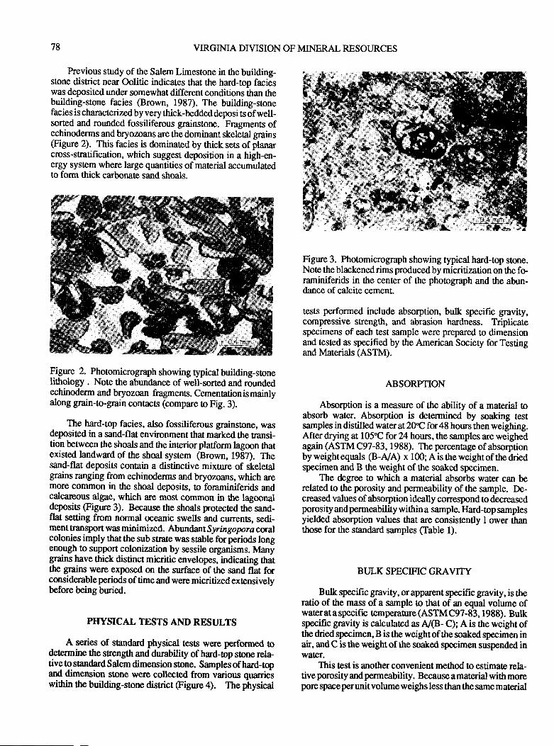
78 VIRGINIA DIVISION OF MINERAL RESOURCES
Previous study of the Salem Limestone in ttre building-stone district near Oolitic indicates that the hard-top facieswas deposited under somewhat different conditions than thebuilding-stone facies (Brown, 1987). The building-stonefacies is characterized by very thick-bedded deposi ts of well-sorted and rounded fossiliferous grainstone. Fragments ofechinoderms and bryozoans are the dominant skeletal grains(Figure 2). This facies is dominated by thick sets of planarcross-stratification, which suggest deposition in a high-en-ergy system where large quantities of material accumulatedto form thick carbonate sand shoals.
Figure 2. Photomicrograph showing typical building-stonelithology . Note the abundance of well-sorted and roundedechinoderm and bryozoan fragments. Cemenadon is mainlyalong grain+o-grain contacts (compare to Fig. 3).
The hard-top facies, also fossiliferous grainstone, wasdeposited in a sand-flat environment that marked the transi-tion between the shoals and the interior platform lagmn thatexisted landward of the shoal system (Brown, 1987). Thesand-flat deposits contain a distinctive mixture of skeletalgrains ranging from echinoderms and bryozoans, which aremore common in the shoal deposits, o foraminiferids andcalcar_eous algae, which are most common in the lagoonaldeposits (Figure 3). Because the shoals protected the sand-flat sering from normal oceanic swells and cunents, sedi-ment transport was minimized. Abundant Syrizgopo ra coralcolonies imply that the sub strate lvas sfable forperiods longenough to support colonization by sessile organisms. Manygrains have thick distinct micritic envelopes, indicating thatthe grains were exposed on the surface of the sand flat forconsiderable periods of time and were micritized extensivelybefore being buried.
PHYSICAL TESTS AND RESULTS
A series of sandard physical tests were performed odetermine the srength and durability of hard-top stone rela-tive !o s0andard Salem dimension stone. Samples of hard-topard dimension stone were collected from various quarrieswithin the building-stone disnict (Figure 4). The physical
Figure 3. Photomicrograph showing typical hard+op stone.Note theblackenedrims producedby micritization on the fo-raminiferids in the center of the photograph and the abun-dance of calcite cement.
tests perfonned include absorption, bulk specific gfavity,compressive sEength, and abrasion hardness. Triplicatespecimens of each test sample were prepared to dimensionand tested as specified by the American Society for Testingand Materials (ASTM).
ABSORPTION
Absorption is a measure of the ability of a material toabsorb water. Absorption is determined by soaking testsamples in distilled waterat20t for48 hours then weighing.After drying at 105€ for 24 hours, the samples are weighedagain (ASTM C97-83,1988). The percentage of absorptionby weight eqruls (B-A/A) x 100; A is the weight of the driedspecimen and B the weight of ttre soaked specimen.
The degree to which a material absorbs water can berelated to the porosity and permeability of the sample. De-creased values of absorption ideally correspond to decreasedporosity andpermeability within a sample. tlard+op samplesyielded absorption values that are consistently I ower thanthose for the standard samples Clable l).
BULK SPECIFIC GRAVITY
Bulk specific gravity, or apparent specific gravity, is theratio of the mass of a sample to ftat of an equal volume ofwaterata specific tempera0re (ASTMC97-83, 1988). Bulkspecific gravity is calculated as A/(B- C); A is the weight ofttrcdriedspecimen, B is the weightof the soaked specimen inair, and C is the weight of the soaked specimen suspended inwater.
This test is anoilrcr convenient method to estimate rela-tive pcosity and permeability. Because a material with morepore spirceperunitvolume weighs less than the same material

VIRGINIA DIVISION OF MINERAL RESOURCES
Previous shrdy of the Salem Limestone in the building-stone district near Oolitic indicates that the hard+op facieswas deposited under somewhat differentconditions than thebuilding-stone facies (Brown, 1987). The building-stonefacies is characterizedby very thick-beddeddeposi tsof well-
cross-stratification, which suggest deposition in a high-en-ergy syst€m where large quantities of material accumulatedto form thick carbonate sand shoals.
figure 2. Photomicrograph showing typical building-stonelithology . Note the abundance of well-sorted and roundedechinoderm and bryozoan fragments. Cementation is mainlyalong grain+o-grain contacts (compare to Fig. 3).
The hard-top facies, also fossiliferous grainstone, wasdeposited in a sand-flat environment that marked the transi-tion between the s
existed landwardsand-flat deposisgrains ranging from echinoderms and bryozoans, which aremore common in the shoal deposis, to foraminiferids and
, which are most common in the lagoonal3). Because the shoals protected ttre sand-normal oceanic swells and currents, sedi-
considerable periods of time and were micritized extensivelybefore being buried.
PHYSICAL TESTS AND RESULTS
Figure 3. Photomicrograph showing typical hard-top stone.Note the blackened rims produced by micritization on the foraminiferids in the center of the photograph and the abun-dance of calcite cement.
tests performed include absorption, bulk specific gravity,compressive strength, and abrasion hardness. Triplicatespecimens of each test sample were prepared to dimensionand tested as specified by ttre American Society for Testingand Materials (ASTM).
ABSORPTION
Absorption is a measure of the ability of a material to
Xf"lg"fi:again (ASTM cs7-83,1988). rhe perce"rr"
"fliol.?fl3fby weightequals (B-A/A) x 100; A is the weightof the driedspecimen and B the weight of ttre soaked specimen.
The degree to which a material absorbs water can berelated to the porosity and permeability of the sample. De-creased values ofabsorption ideally correspond o decreasedporosity and permeability wittrin a sample. tlard-top samplesyielded absorption values that are consistently I ower thanthose for the standard samples (Table 1).
BULK SPECIFIC GRAVITY
Bulk specific gravity, or apparent specific gravity, is theratio of the mass of a sample to that of an equal volume ofwater at a specific bmperature (ASTM C97-83, 1988). Bulkspecific gravity is calculated as A/(B- C); A is the weight ofthe dried qpecimen, B is the weight of the soaked specimen inair, and C is the weight of the soaked specimen suspended in\vater.
This test is another convenient method to estimate rela-tive porosity and permeability . Because a material with morepore speeperunitvolume weighs less than the same material
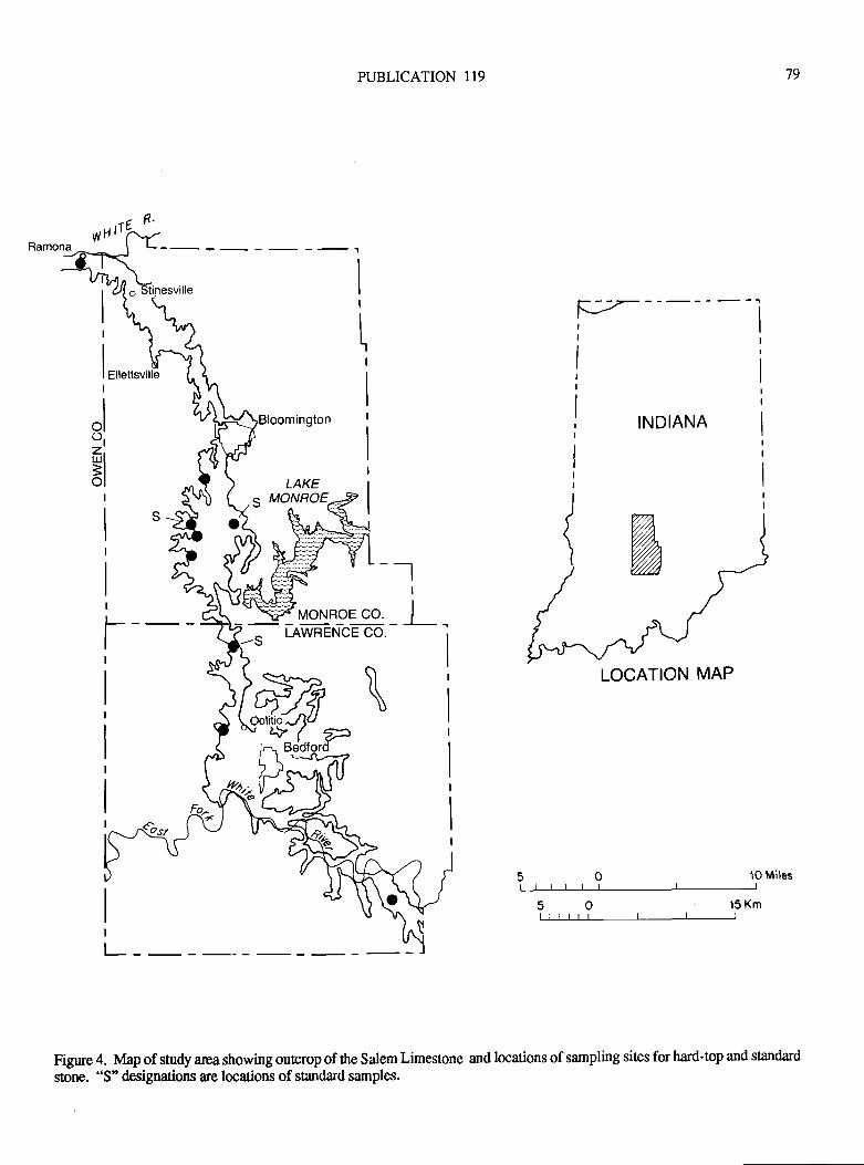
PUBLICATION 119
-_l
Y"o[tgE co - ]- _
-; Inwn-rr'r-ce co - - I
'79
,-l R'yyH |, r\.,
tr7
I
"lot
xt
INDIANA
LAKEMONROES
10 Miles
'15 Km
Figrne 4. Map of study area showing outcrop of the Salem Limestone and locations of sampling sites for hard+op and standard
stone. "S" designations are locations of standard samples.
LOCATION MAP
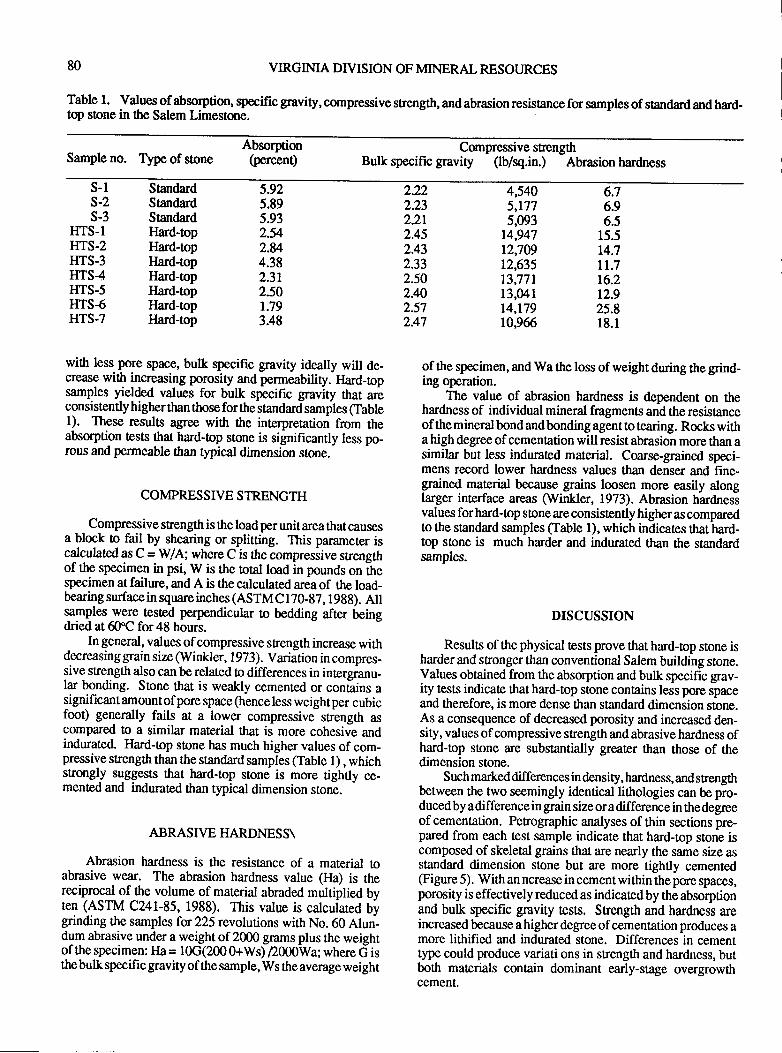
80 VIRGIMA DIVISION OF MINERAL RESOURCES
Table l. Values of absorption, specific gravity, compressive strength, and abrasion resistance for samples of standard and hard-top stone in the Salem Limestone.
Sample no. Type of soneAbsorption
(percent)Compressive srength
Bulk specific gravity (lb/sq.in.) Abrasion hardness
s-ls-2s-3
HTS-1IITS-2IilS.3IITS4IITS-5ITTS-6r{rs-7
StandardStandardStandardIlard-topIlard-lopllard+opIlard-topIlard-lopIlard-topIlard+op
5.925.895.932.542.U4.382.3r2.501.793.48
4,5405,1775,093
14,94712,70912,635t3,77113,04114,I7910,966
2.222.232.212452.432.332.502.442.572.47
6.76.96.5
15.514.7It.7t6.212.925.8r8.1
with less pore space, bulk specific gravity ideally will de-crease with increasing porosity and permeability. Ilard-topsamples yielded values for bulk specific gravity that areconsistently higher than those for the standarA samptas (Table1). These results agree with the interpretation from theabsorption tests that hard-top stone is significantly less po-rous and permeable than fypical dimension stone.
COMPRESSIVE STRENGTH
Compressive srength is the loadperunit areathatcausesa block o fail by shearing or splitting. This parameter iscalculated as C = WAi where C is the compressive strengthof the specimen in psi, W is the total load in pounds on thespecimen at failure, and A is the calculated area of the load-bearing surface in square inches (ASTM C I TG.8Z, 1 9Sg). Allsamples,were lested perpendicular to bedding after beingdried at 60"C for 48 hours.
In general, values of compressive strength increase withdecreasing grain size (tVinkl er, 1973). Variation in compres-sive strength also can be related to differences in intergranu-lar bonding. Stone that is weakly cemented or con6ins asignificantamountofpore space (henceless weightper cubicfoot) generally fails at a lower compressivc strength ascompared to a similar material that is more cohesive andindurated- Flard-top stone has much higher values of com-pressive strength than the standard samples (Table 1) , whichstrongly suggests that hard*op stone is more tightly ce-ment€d and indurated than typical dimension stone.
ABRASIVE HARDNESS\
Abrasion hardness is the resistance of a material toabrasive wear. The abrasion hardness value (Ha) is thereciprocal of the volume of material abraded multiplied byten (ASTM C241-85, 1988). This value is calculated bvgrinding the samples for225 revolutions with No.60 Alun-dum abrasive under a weight of 2000 grams plus the weightof the specimen: Ha = 10G(200 0+Ws) Z000Wa; where d isthe bulk specific gravity of the sample, Ws the average weight
of the specimen, and Wa the loss of weight during the grind-ing operation.
The value of abrasion hardness is dependent on thehardness of individual mineral fragments and the resistanceof the mineral bond andbonding agent to tearing. Rocks witha high degreeof cementation will resist abrasion more than asimilar but less indurated material. Coarse-grained speci-mens record lower hardness values than denser and fine-grarned material because gtains loosen more easily alonglarger interface areas (Winkler, 1973). Abrasion hardnesivalues forhard-top stone are consistently higheras comparedto the standard samples (Iable 1), which indicates that hard-top stone is much harder and indurated than the standardsamples.
DISCUSSION
Results of the physical tests prove that hard-op stone isharderand stronger than conventional Salem building stone.Values obtained from the absorption and bulk specific grav-ity tests indicate that hard-top stone contains less pore spaceand therefore, is more dense than standad dimension stone.As a consequence of decreased porosity and increased den-sity, values ofcompressive sfiength and abrasive hardness ofhard-top stone are substantially greater than those of thedimension stone.
Such markeddifferences in density, hardness, and srengthbetween the two seemingly identical lithologias can be pro-duced by a difference in grain size or a difference in the degreeof cementation. Perographic analyses of thin sections pre-pared from each test sample indicate that hard-top stone iscomposed of skeletal grains that are nearly the same size asstandard dimension stone but are more tightly cemented(Figure 5). With an ncrease in cement within the pore spaces,porosity is effectively reduced as indicated by the absorptionand bulk specific gravity tests. Strength and hardness areincreased because a higher degree ofcementation produces amore lithified and indurated stone. Differences in cement.type could produce variati ons in strength and hardness, butboth materials contain dominant early-stage overgrowtfrcemenL
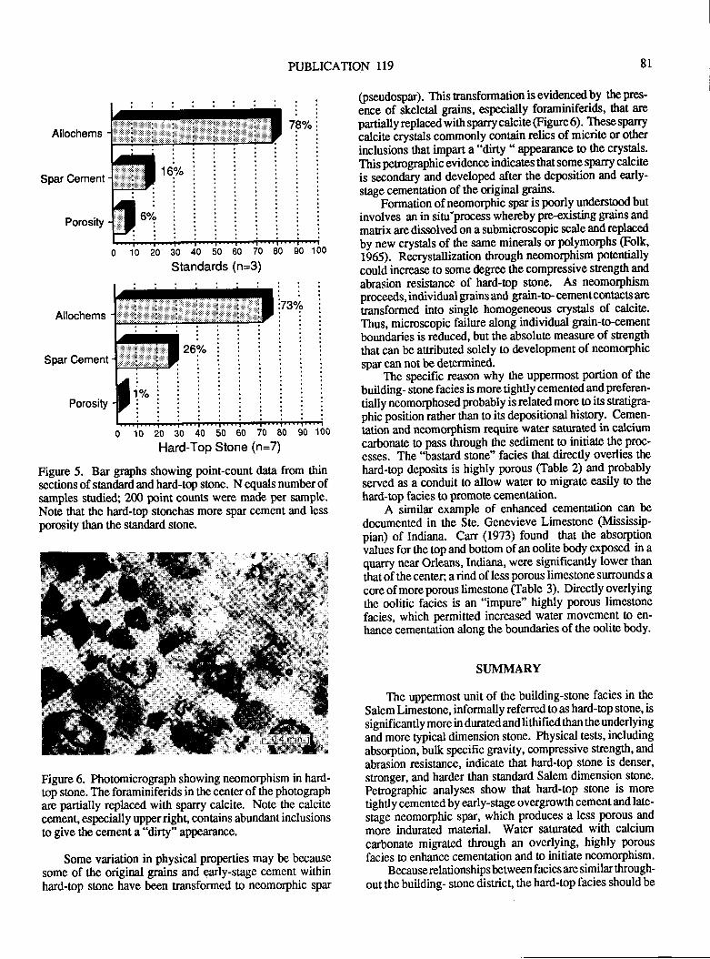
PUBLICATION 119 8r
Allochems
Spar Cement
Porosity
Allochems
Spar Cement
Porosity
0 10 20 30 40 50 60 70 E0 90 ]u(
Hard-Top Stone (n=7)
Figure 5. Bar graphs showing point-count data from thinsections of standard and hard-top stone. N equals number ofsamples snrdied; 200 point counts were made per sample.Note that the hard-top stonehas more spar cement and less
porosity than the standard stone.
Figure 6. Photomicrograph showing neomorphism in hard-top sone. The foraminiferids in the center of the photographare partially replaced with sparry calcite. Note the calcitecement" especially upper righl contains abundant inclusionso give the cement a "dirty" appeiuance.
Some variation in physical properties may be becausesome of the original grains and early-stage cement withinhard-top stone have been transformed to neomorphic spar
(pseudoqpar). This ransformation is evidenced by the pres-
ence of skeletal grains, especially foraminiferids, that arepartially replaced with sparry calcite (Figure 6) . These sparry
iAcite cryitals commonly contain relics of micrile or other
inclusions that impart a "difty " appearance to the crystals.
This petrographic evidence indicates that some sparry calcite
is secondary and developed after the deposition and early-
stage cementation of the original grains'-
Formation of neomorphic spar is poorly understood butinvolves an in sinr'process whereby pre-existing grains and
matrix are dissolved on a submicroscopic scale and replaced
by new crystals of the same minerals or polymorphs (Folk,t9OS1. necrystallization ttrough neomorphism potentially
could increase to some degree the compressive strength and
abrasion resistance of hard-op sone. As neomorphismproceeds, individual grains and grain-o- cementcontacts are
transformed into single homogeneous crystals of calcite.Thus, microscopic failure along individual grain-to-cement
boundaries is reduced, but the absolute measrue of sfengththat can be auributed solely to development of neomorphic
spar can not be determined.- The specific reason why the uppermost portion of the
building- stone facies is more tightly cemented and preferen-
tially neomorphosed probably is related more to its stratiga-phic position ra*rer than to its depositional history. Cemen--tation
and neomorphism require water saturated in calcium
carbonate to pass through the sediment to initiate the proc-
esses. The "bastard stone" facies that directly overlies the
hard-top deposits is highly porous (Iable 2) nd probably
served as a conduit to allow wat€r to migrate easily o the
hard-top facies to promote cemenbtion.A similar example of enhanced cementation can be
documented in the Ste. Genevieve Limestone (Mississip-
pian) of Indiana. Can (1973) found that the absorptionvalues for the top and bouom of an oolite body exposed in aquarry near Orleans, Indiana, were significantly lower than
thatof thecenter; arind of less porous limestone surrounds a
core of more porous limesone (Table 3). Directly overlyingthe oolitic facies is an "impure" highly porous limestone
facies, which permitted increased water movement to en-
hance cementation along the boundaries of the oolite body.
SI.JMMARY
The uppermost unit of ttre building-stone facies in the
Salem Limestone, informally referredto as hard-top stone, is
significantly more in durated and lithified than the underlyingand more typical dimension stone. Physical tes[s, includingabsorption, bulk specific gravity, compressive strength, and
abrasion rgsistance, indicate that hard+op stone is denser'
stronger, and harder than standard Salem dimension stone.
Perographic analyses show that hard-top stone is more
tightly cemented by early-stage overgrowtl cement and late-
stage neomorphic spar, which produces a less porous and
moie indurated material. Water saturated with calcium
carbonate migrated through an overlying, highly porous
facies to enhance cementation and to initiate neomorphism.Because relationships between facies are similar through-
out the building- sone district, the hard-top facies should be
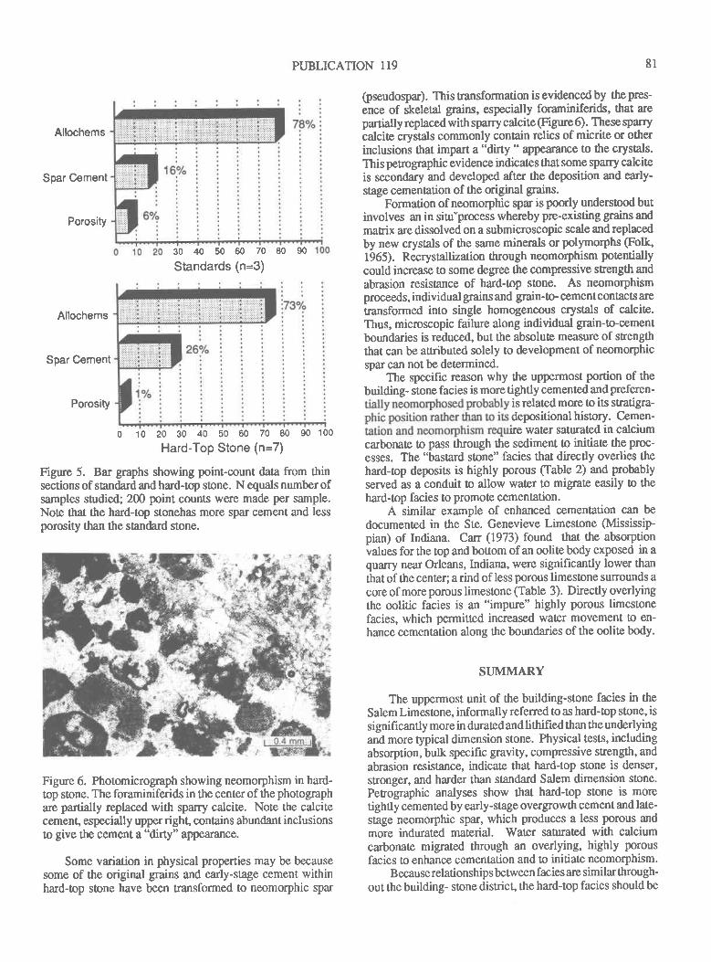
PUBLICATION I19 8l
Allochems
Spar Cement
Porosity
30 40 50 60 70 80 90
Standards (n=3)
Allochems
Spar Cement
Porosity
o 10 20 30 40 50 60 70 80 90 100
Hard-Top Stone (n=7)
Figure 5. Bar graphs showing point-count data from thinsections of standard and hard-top stone. N equals number ofsamples sfirdied; 200 point counts were made per sample.Note that the hard+op slonehas more spar cement and lessporosity than the soandard stone.
Figure 6. Photomicrograph showing neomorphism in hard-top stone. The foraminiferids in the center of tlre photographare partially replaced with sparry calcite. Note the calcitecement" especially upper right, contains abundant inclusionslo give the cement a "dirty" appearance.
Some variation in physical properties may be becausesome of the original grains and early-stage cement withinhard-top stone have been transformed to neomorphic spar
(pseudospar). This tansformation is evidenced by the pres-
ence of sketetal grains, especially foraminiferids, that arepartially replaced with sparry calcite (Figure 6). These sparrycalcite crystals commonly contain relics of micrite or otherinclusions ttrat impart a "dirty " appearance to the crystals.
This perographic evidence indicates that some sparry calciteis secondary and developed after the deposition and early-stage cementation of the original grains.
Formation of neomorphic spar is poorly understood butinvolves an in sinr-process whereby pre-existing grains andmatrix are dissolved on a submicroscopic scale and replaced
by new crystals of the same minerals or polymorphs @olk,1965). Recryslallization through neomorphism potentially
could increase to some degree the compressive strength and
abrasion resistance of hard-top sone. As neomorphismproceeds, individual grains and gfain-o- cementcontacts are
transformed into single homogeneous crystals of calcite.Thus, microscopic failure along individual grain-to-cementboundaries is reduced, but the absolute measure of sfengththat can be auributed solely to development of neomorphicspar can not be determined.
The specific reason why ttre uppennost portion of thebuilding- stone facies is more tightly cemented and preferen-
is related more to its stratigra-depositional history. Cemen-ire water saturated in calcium
carbonate to p:rss through the sediment to initiate the proc-esses. The "bastard stone" facies that directly overlies thehard-top deposits is highly porous Clable 2) and probably
served as a conduit to allow water to migrate easily o thehard-top facies to promote cementation.
A similar example of enhanced cementation can be
documented in the Ste. Genevieve Limestone (Mississip-pian) of Indiana. Can (1973) found that the absorptionvalues for the top and bouom of an oolite body exposed in aquarry near Orleans, Indiana, were significantly lower than
that of the center; a rind of less porous limestone sulrounds a
core of more porous limestone (Table 3). Directly overlyingthe oolitic facies is an "impure" highly porous limestonefacies, which permitted increased water movemen[ to en-hance cementation along the boundaries of the oolite body.
SI.JMMARY
The uppermost unit of the building-stone facies in the
Salem Limestone, informally refened to as hard-top stone, is
signif,rcantly more in durated and lithified than the underlyingand more typical dimension stone. Physical tests, includingabsorption, bulk specific gravity, compressive strengti, and
abrasion resistance, indicate that hard-op stone is denser,
stronger, and harder than standard Salem dimension stone.
Petrographic analyses show Otat hard-top stone is more
tightly cemented by early-stage overgrowth cement and late-stage neomorphic spar, which produces a less porous andmore indurated material. Water sa[rated wittt calciumcarbonate migrated through an overlying, highly porous
facies to enhance cemenlation and o initiate neomorphism.Becauserelationships between facies are similar through-
out the building- sone district, the hard-top facies should be
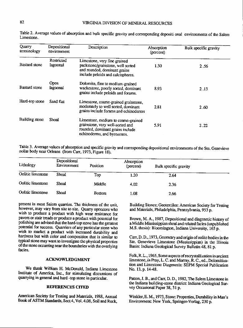
82 VIRGIMA DIVISION OF MINERAL RESOURCES
JSble 2' Average values of absorption and bulk specific gravity and corresponding depositi onal environments of the SalemLimestone.
Quarryterminology
Depositionalenvironment
Description Absorption(percent)
Bulk specific gravity
Bastard stone
Bastard stone
Ilard-top stone
Resrictedlagoonal
Openlagoonal
Sand flat
Building stone Shoal
Limestone, very fine grainedpackstone/gfainstone, well sortedand rounded, dominant grainsinclude peloids and calcispheres.
Dolomite, fine to medium-grainedwackestone, poorly sorted, dominantgrains include peloids and forams.
Limestone, coarse-grained grainstone,moderately to well sorted, dominantgrains include forams and echinoderms
Limestone, medium to coarse-grainedgrainstone, very well-sorted androunded, dominant grains includeechinoderm s, and byrozoans.
1.30 2.56
2.r3
2.ffi
2.22
8.93
2.8r
5.91
ralb J. Average-values ofabsorption and specific gravity and corresponding depositional environments of the Ste. Genevieveoolite body near Orleans (from Carr, 1973, Figure iS).
-
LithologyDepositionalEnvironment
AbsorptionPosition (percent) Bulk specific gravity
Oolitic limestone
Oolitic limestone
Oolitic limestone
Shoal
Shoal
Shoal
Top
Middle
Bottom
r.20
4.02
1.08
2.&
2.36
2.6
Building Stones; Geotextiles: American Society for Testingand Materials, Philadelphia, Pennsylvania, 953 p.
Brown, M. A., 1987, Depositional and diagenetic history ofa Middle Mississippian shoal and related facies (unpublishedM.S. thesis): Blmmington, Indiana University, 165 p.
Carr, D. D. , I 973 , Geometry and origin of mlite bodies in theSte. Genevieve Limestone (Mississippian) in the IllinoisBasin: Indiana Geological Survey Bulletin 48, 8l p.
Folk, R. L., 1965, Someaspects ofrecrystallization inancientlimestone, iz Pray, L. C. and Murray, R. C., ed., Dolomitiza-tion and Limestone Diagenesis: SEPM Special PublicationNo. 13, p. 1448.
Pason, J. B., and Carr, D. D., 1982, The Salem Limestone inthe Indiana building-stone districc Indiana Geological Sur-vey Occasional Paper 38, 3l p.
Winkler,E. M., 1973, Stone: Properties, Durability in Man'sEnvironmenu New Yor*, Springer-Verl ag, 230 p.
present in most Salem quarries. The thickness of the unit,hgryever, may vary from site o site. euarry operators whowish to produce a product with high wear resistance forpavers or stair reads or produce a product with potential forpolishing are advised that the hard+op stone hasthe geatestpotential for success. Quarriers of any particular stone whowish to yarkel a product with increased durability andhardness but with color and composition that is similar tot{pi"ul stone may want to investigate the physical propertiesof the stone occurring near the boundaries with Brebverlyingfacies.
ACKNOWLEDGMENT
We thank William H. McDonald, Indiana LimestoneInstitute of America, [nc., for stimulating discussions ofquarrying in general and hard -top stone in particular.
REFERENCES CITED
American Society for Testing and lvlaterials, l9gg, AnnualBook of ASTM Standards, Sect4, VoI.4.08, Soil and Rock,
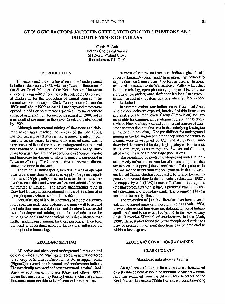
PUBLICATION 119
GEOLOGIC FACTORS AFFECTING THE UNDERGROUND LIMESTONE ANDDOLOMITE MINES OF INDIANA
Curtis H. AultIndiana Geological Survey611 North Walnut GroveBloomington, IN 47405
83
INTRODUCTION
Limestone and dolomite have been mined undergroundin Indiana since about 1832, when argillaceous limestone ofthe Silver Creek Member of the North Vernon Limestone(Devonian) was minedfrom thenorth bankof theOhioRiverat Clarksville for the production of natural cemenL Thenatural-cement indus!ry in Clark County boomed from the1860s until about 1900; at least I 1 underground mines wereopened in addition to numerous quarries. Portland cementreplaced natural cement for most uses soon after 1900, and asa result all of the mines in the Silver Creek were abandonedby 1909.
Altlough underground mining of limestone and dolo-mite never again reached the heyday of the late 1800s,shallow underground mining has assumed gireater impor-tance in recent years. Limestone for crushed-stone uses isnow produced from three modern underground mines in andnear Indianapolis and from one in Crawford County; lime-stone forgliass flux is mined undergroundin MonroeCounty;and limesone for dimension stone is mined underground inl,awrence County. The latter is the first underground dimen-sion-slone mine in the sAe.
The mines at Indianapolis, two drift mines in open-pitquarries and one slope-shaft mine, supply a large metropoli-tan areawith high-quality construction stone in an area whereoverburden is thick and where surface land suiable for open-pit mining is limited. The active underground mine inCrawford County allows continued mining of limestone at anopen-pit quarry where overburden is thick.
As surface use of land in other areas of the state becomesmore concentrated, more underground mines will be neededto obtain limestone and dolomite, and the already successfuluse of underground mining methods to obtain stone forbuilding materials and the chemical indusries will encouragefurther underground mining for these purposes. Therefore,the need to understand geologic faclors that influence themining is also increasing.
GEOLOGIC SETTING
All active and abandoned underground limestone anddolomiteminesin Indiana @gurel) are atornear theoutcropor subcrop of Silurian , Devonian, or Mississippian rocks
@gure 2) in cenral, south-central, and southeastern Indiana.These rocks dip westward and southwestward into the IllinoisBasin in southwestern Indiana (Gray and others, 1987),where they are ovedain by Pennsylvanian rmks that containlimestone straca too thin to be of economic importance.
In most of central and northern Indiana, glacial driftcovers Silurian, Devonian, and Mississippian age bedrock todepths that reach more than 400 feet in places. In somerestricted areas, such as the Wabash River Valley where driftis thin or missing, open-pit quarrying is possible. In these
areas, shallow underground shaft or drift mines also have po-tential, particularly in stone quarries where surface expan-sion is limited.
In extreme southeaslern Indiana on the Cincinnati Arch,where older rocks are exposed, interbedded thin limestonesand shales of the Maquoketa Group (Ordovician) that are
unsuitable for commercial development are at the bedrocksurface. Nevertheless, potential coinmercial sources of lime-stone occur at depth in this area in the underlying LexingtonLimestone (Ordovician). The possibilities for undergroundmining in *re Lexington and other deep limesone strata inIndiana were investigated by Carr and Ault (1983), whodescribed the potential for deep highquality carbonate rockin IaPorte, Vigo, Vanderburgh, and Switzerland Counties,all of which have or are near large populations.
The orientation of joins in undergtound mines in Indiana directly affects the orienadon of rooms and pillars thatare needed 0o support jointed roof rock. Joint patterns inIndiana are consistent with regional patterns in the midwest-em United States, which arebelieved to be related to contem-porary stress conditions in the littrosphere @ngelder, 1982) .
As mapped by Ault (1989) in most of Indiana, primary joins(the most prominent joints) have a prefened east-northeast-erly direction, and secondary joints (less prominent) have anorth-northwesterly direction.
The prediction of jointing directions has been investi-gated in open-pit quarries in northern Indiana (Ault" 1988),in two underground limestone and dolomite mines atlndian-apolis (Ault and llaumesser, 1990), and in the New AlbanyShale (Devonian-Silurian) of southeastern Indiana (Ault,1990). These studies found that, even though local variationsmay be present, major joint directions can be predicted owithin a few degees.
GEOLOGIC CONDITIONS AT MINES
CLARK COUNTY
Abandoned naBral-cement mines
An argillaceous dolomitic limestone thatcan be calcineddirectly into cement without 0re addition of other raw mate-rials was extracted from the Silver Creek Member of theNorth Vernon Limestone (Table l) in underground limesonq
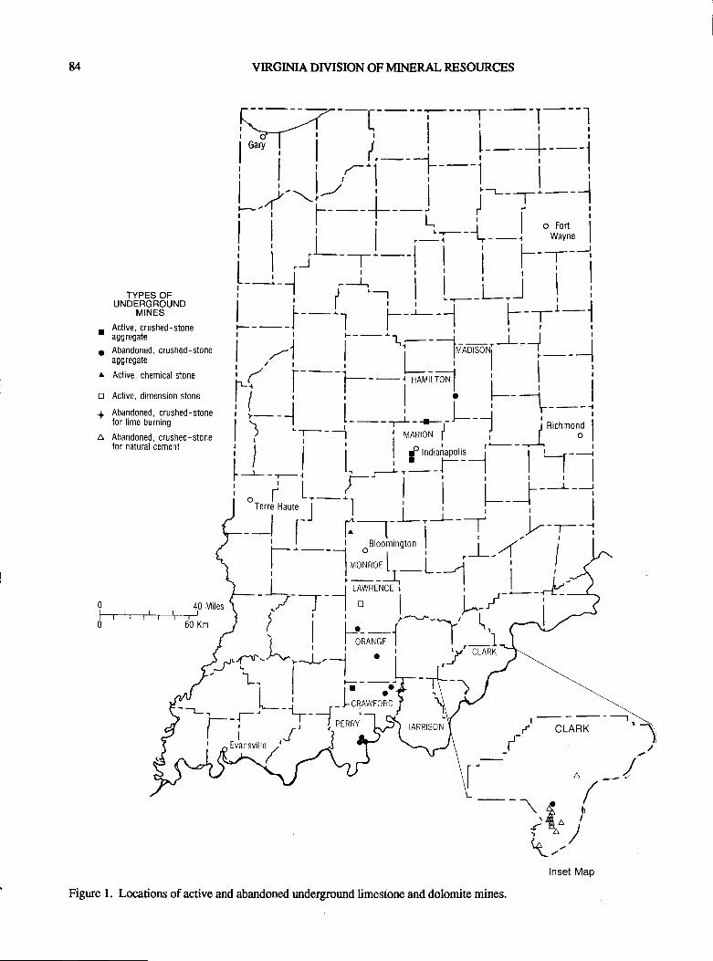
u VIRGINIA DIVISION OF MINERAL RESOURCES
ll-lli,i i I L__L '
I r.----l r i-]leavi I l,-) f-+-1i | , '''1, i-l---_l__jl_..2--Y_f _l j--T'---,i i i i ,5,- r, -l ''^r,n,
i
I
O
A
D
+
A
| | i i .:r-t-l ',,f;,n, 1
i iir--,r-l I i f -[-iTYPES.F i-j i*'-, I i--t---J I i
uruoenGnouru" I i___l_, ; i j---F_-.'_i_jActive,crushed_stgne |____l | | I i i r
aggregate | | ^r --
i | | |
Abandoned, crushed-stone | ) |
tl lrvrnosor{ -]assresate ! .,tl : I i^"'""''l i--',
Acrive, chemicarsrone ;( [-- 1----i*r-A-l I I '
Acrive d,mensi'n stone l-i i i I i t-- -i I
Abandoned.crushed-srone I l--l | | r i F----1
itlffiI:i:lhed-stone l) l---j-,fi;;fr-/ --l fncn'o'olr0rnaturalcement i I i i I gornoi.irpo'l_j -l*-----..
l_ { _.,_l r. _--L,- r-_l | | |itt r'li i F-i---r| ;l )I
orr..,'J Hrrtr'i-'l
t__t__i oo,uu,,,,,,stu,, i , )r_-4 I
I lrvroNROE [,_ L__-1 i J
I l---+ | | t.;I ILAWRENCET | | --l/
-a L--
4oMiles t- ? -:--J'Y*'*" i L^-/---{-f*') ( iF:,^,*1'--l'lr-*l{iI p.4rl-l'r-"J-tJ!l
i ;'-cmnR
; t r I i t__f ..'oTe..JHartr'i-'l i i | ,
-l i' f-:-, ti- -r .v T
t-t- 1,.':':i:' L ; )-'1 !
a) dt4-r-\' -"^J--- - | ,,J,r( ti- ] i:--x:F t- );-F-[* r $:fJ***M / CLARK
d-liJ'idHT'
^a\:A\2s a
-< 4"">4(^\.-
I
Figure 1. Locations of active and abandoned underground limestone and dolomite mines.
Inset Map
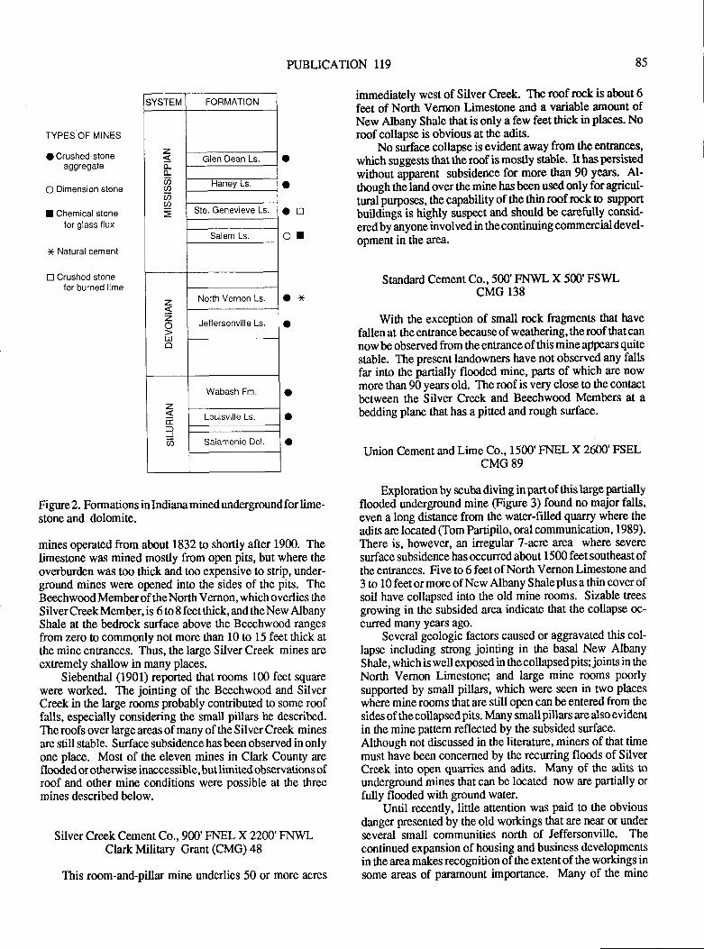
PUBLICATION 119 85
TYPES OF MINES
O Crushed-stoneaggregale
O Dimension stone
I Chemical stonefor glass flux
* Natural cement
E Crushed stoneJor burned lime
SYSTEM FORMATION
z
6U)U)
Glen Dean Ls
Haney Ls
Ste. Genevieve Ls.
Salem Ls
zzLUo
North Vernon Ls
Jeffersonville Ls.
zgE.:)J
Wabash Fm.
Louisville Ls
Salamonie Dol.
o
aoor
oxa
Figure 2. Formations in Indiana mined undergtound for lime-stone and dolomite.
mines operated from about 1832 to shortly after 1900. Thelimestone was mined mostly from open pits, but where theoverbuden was too thick and too expensive to strip, under-gound mines were opened into the sides of the pits. TheBeechwood Member of the North Vernon, which overlies theSilver Creek Member, is 6 to 8 feet ttrick, and the New AlbanyShale at the bedrock surface above the Beechwood rangesfrom zero to commonly not more than l0 to 15 feet thick atthe mine entrances. Thus, the large Silver Creek mines areextremely shallow in many places.
Siebenthal (1901) reported tlat rooms lCI feet squarewere worked. The jointing of the Beechwood and SilverCreek in the large rooms probably contributed to some rooffalls, especially considering the small pillars he described.The roofs over large areas of many of the Silver Creek minesare still stable. Surface subsidence has been observed in onlyone place. Most of the eleven mines in Clark County areflooded or otherv/ise inaccessible, but limited observations ofroof and other mine conditions were possible at the threemines described below.
Silver Creek Cement Co., 900'FNEL X 2200'FNWLClark Military Grant (CMG) 48
This room-and-pillar mine underlies 50 or more acres
immediately west of Silver Creek. The roof rock is about 6feet of North Vernon Limeslone and a variable amount ofNew Albany Shate that is only a few feet thick in places. Noroof collapse is obvious at the adits.
No surface collapse is evident away from the entrances,
which suggests that the roof is mostly stable. It has persisted
without apparent subsidence for more tlnn 90 years. Al-though theland over the mine hasbeen used only foragricul-tural purposes, the capability of the thin roof rock o supportbuildings is highly suspect and should be carefully consid-ered by anyone involved in the continuing commercial devel-opment in the area.
Standard Cement Co.,500'FIML X 500'FSWLcMG 138
With the exception of small rock fragments that have
fallen at lhe entrance because of weathering, tle roof that can
now be observed from the entrance of this mine appears quite
stable. The present landowners have not observed any fallsfar into the partially flooded mine, parts of which are nowmore than 90 years old. The roof is very close to fite contactbetween the Silver Creek and Beechwood Members at abedding plane that has a piced and rough surface.
Union Cement and Lime Co., 1500'FNEL X 2600'FSELCMG 89
Exploration by scuba diving in part of this large partiallyflooded undergtound mine (Figure 3) found no major falls,even a long distance from the water-filled quarry where the
adis are located (Tom Partipilo, oral communication, 1989).There is, however, an irregular 7-acre area where severe
surface subsidence has occuned about I 500 feet southeast ofthe entrances. Five to 6 feet of North Vernon Limestone and
3 to 10 feet or more of New Albany S hale plus a thin cover ofsoil have collapsed into the old mine rooms. Sizable treesgrowing in the subsided area indicate that the collapse oc-
curred many years ago.Several geologic factors caused or aggravated this col-
lapse including strong jointing in ttre basal New AlbanyShale,whichiswell exposed in thecollapsedpis; joints in theNorth Vernon Limestone; and large mine rooms poorlysupported by small pillan, which were seen in nvo places
where mine rooms that are still open can be entered from the
sidesof thecollapsedpits. Many smallpillars are also evidentin the mine patlern reflected by the subsided surface.Although not discussed in the literature, miners of tlnt timemust have been concerned by the recurring floods of SilverCreek into open quarries and adis. Many of the adis ounderground mines thatcan be located now are partially orfully flooded with ground water.
Until recently, little attention was paid to the obviousdanger presented by the old workings that are near or underseveral small communities north of Jeffenonville. Thecontinued expansion of housing and business developmentsin the area makes recognition of the extentof the workings insome areas of paramount importance. Many of the mine
o
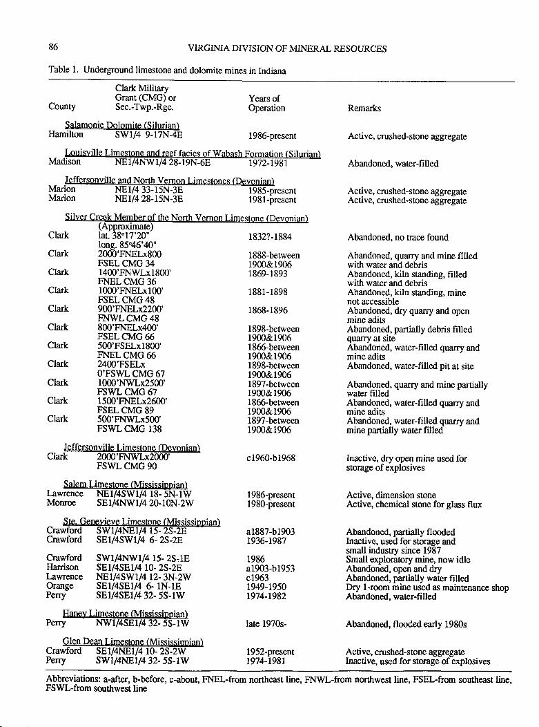
86 VIRGINIA DIVISION OF MINERAL RESOLR.CES
Table 1. Underground limestone and dolomite mines in Indiana
- - .l.ouisvitte t-irlgslrl!=ejulqryMadison NEI/4NW1/4 28-19N-6E --ffiT.'9{r-
Clark MilitaryGrant (CMG) or
County Sec.-Twp.-Rge.
$alamonie Dolomite (Silurian)Hamilton SWI/4 9-17N-48
Remarks
Active, crushed-stone aggrcgate
Abandoned, water-fi lled
Active, crushed-sione aggegateActive, crushed-stone aggregate
Abandoned, no oace found
Abandoned, quarry and mine filledwith water and debrisAbandoned, kiln standing, filledwith water and debrisAbandoned, kiln standing, minenot accessibleAbandoned, dry quarry and openmine aditsAbandoned, partially debris filledquarry at siteAbandoned, water-filled quarry andmine aditsAbandoned, water-filled pit at site
Abandgned, quarry and mine paniallywater filledAbandoned, water-filled quarry andmine aditsAbandoned, water-filled quarry andmine partially water filled
Inactive, dry open mine used forstorage ofexplosives
Active, dimension stoneActive, chemical stone for glass flux
Abandoned, partially flmdedInactive, used for storage andsmall industry since 1987Small exploratory mine, now idleAbandoned, open and dryAbandoned, partially water filledDry l-room mine used as maintenance shopAbandoned, water-filled
Abandoned, flooded early 1980s
Active, crushed-stone aggregateInactive, used for storage of explosives
NE1/4 33-tNEl/4 28-15N-38
Years ofOperation
1986-present
l98l-presentMarionMarion
Silver Crgek Meqrber qf the North Vernon Limestone (Devonian)(Approximate)
Clark lat.38"17'20" 1832?-1884
Clark
Clark
Clark
Clark
Clark
Clark
Clark
Clark
Clark
Clark
FSWL CMG 90
Salem Limestone (Mississionian)Lawrence NE1/4SW1/4 18- 5N-1WMonroe SE1/4l.IlV1/420-10N-2W
_ SIe. 9ene=vieve Limestone (Mississipnian)Crawford SWI/4NEI/4 15-25-2E.Crawford SEl/4SWl/4 6- 25-28
Crawford SWl/4f.nVl/4 15- 25.18Ilarrison SE1/4SE1/4 10- 2S-2ELawrence NE1/4SW1/4 12- 3N-2WOrange SE1/4SEI/4 G lN-lEPerry SEl/4SEl/4 32- 5S-1W
Haney Lilnestone (Mississippian)Psrry l.Mli4SEl/4 32- 5S-lW
long.85'46'40"2000'FNELx800FSEL CMG 341400'FNWLx1800'FNELCMG 361000'FNELx100'FSEL CMG 48900'FNELX2200'F\T}VLCMG48800'FNELx400'FSEL CMG 65500'FSELx1800'FNEL CMG 662400'FSELxO'FswL cMG 671000'NWLx2500'FSWL CMG 671500'FNELx2600'FSEL CMG 89500'FNWLx500'FSWLCMG 138
1888-between1900&19061869-1893
1881-1898
1868-1896
1898-benveen1900&19061865-between1900&19061898-benveen19m&19061897-between1900&r9061866-between1900&19061897-betrveen1900&1906
c1960-b1968
1986-present1980-present
a1887-b19031936-1987
1986a1903-b1953c19631949-1950r974-1982
late 1970s-
1952-present1974-r98rPerry swl/4NE1/4 32- 55-lW
Abbreviations: a-after, b-before, c-about, FNEL-from northeast line, FNWL-from northwest line, FSEL-from southeast line,FSWL-from southwest line
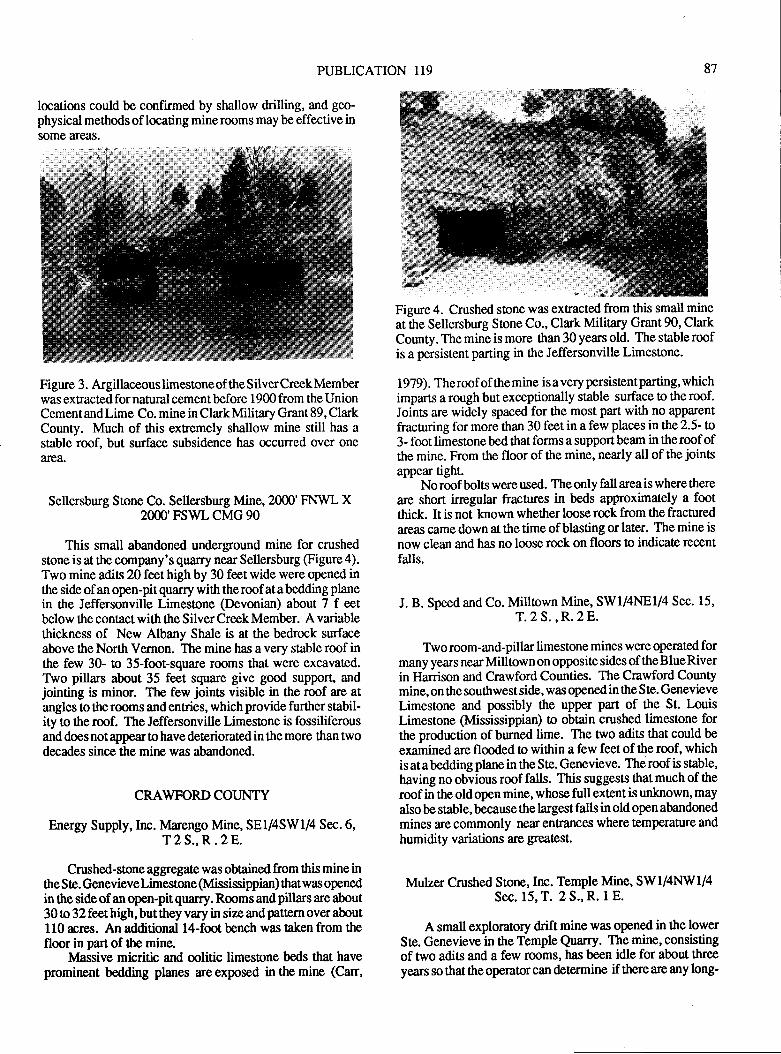
PUBLICATION 119
locations could be confirmed by shallow drilling, and geo-physical methods of locating minerooms maybe effective insome areas.
Figure 3. Argillaceouslimestoneof the SilverCreekMemberwas extracted for natual cement before 1900 from the UnionCement and Lime Co. mine in Clark Military Grant 89, ClarkCounty. Much of this extremely shallow mine still has astable roof, but surface subsidence has occurred over onearea.
Sellersburg Stone Co. Sellersburg Mine,2000'FNWL X2000'FswL cMG 90
This small abandoned underground mine for crushedstone is at the company's quarry near Sellersbwg @gure4).Two mine adis 20 feet high by 30 feet wide were opened inthe side of an open-pitquarry with theroof atabedding planein the Jeffersonville Limestone (Devonian) about 7 f eetbelow the contact with the Silver Creek Member. A variablethickness of New Albany Shale is at the bedrock surfaceabove the North Vernon. The mine has a very stable roof inthe few 30- o 35-foot-square rooms that were excavated.Two pillars about 35 feet square give good support, andjointing is minor. The few joins visible in the roof are atangles to therooms andentries, which provide further stabil-ity o the roof. The Jeffenonville Limestone is fossiliferousand does not appear to have deteriorated in the more than twodecades since the mine was abandoned.
CRAWFORD COUNTY
Energy Supply,Inc. Marengo Mine, SE1/4SW1/4 Sec.6,T2S.,R.2E.
Crushed-stone aggregale was obtained from this mine inthe Ste. Genevieve Limestone (Mississippian) that was openedin the side of an open-pit quarry. Rooms and pillars are about30 o 32 feet high, but they vary in size and pattern over about110 acres. An additional l4-foot bench was taken from thefloor in part of the mine.
Massive micritic and mlitic limestone beds that haveprominent bedding planes are exposed in the mine (Can,
Figure 4. Crushed stone was extracted from this small mineat the Sellersburg Stone Co., Clark Miliary Grant 90, ClarkCounty. The mine is more than 30 years old. The stable roofis a persistent paring in the Jeffersonville Limestone.
1979). The roof of the mine is a very persistent parting, whichimparts a rough but exceptionally stable surface to the roof.Joints are widely spaced for the most part with no apparent
fracturing for more than 30 feet in a few places in the 2'5- to3 - foot limestone bed that forms a support beam in the roof ofthe mine. From the floor of the mine, nearly all of the joints
appear tight.No roof bolts were used. The only fall area is where there
are short irregular fractures in beds approximately a footthick. It is not lnown whether loose rock from the fractured
areas came down at the time of blasting or later. The mine is
now clean and has no loose rock on floors o indicate recent
falls.
J. B. Speed and Co. Milltown Mine, SW1/4NE1/4 Sec. 15,
T.2 S.,R.28.
Two room-and-pillar limestone mines were operated formany years nearMilltownon oppositesides of theBlueRiverin Harrison and Crawford Counties. The Crawford Countymine, on the southwest side, was opened in the Ste. Genevieve
Limestone and possibly ttre upper part of the St. LouisLimestone (Mississippian) o obtain crushed limestone forthe production of burned lime. The two adits that could be
examined are flooded o within a few feet of the rmf, whichis at a bedding plane in the S te. Genevieve. The roof is stable,having no obvious roof falls. This suggests that much of the
roof in the oldopen mine, whose full extentis unlnown, mayalso be stable, because the largest falls in old open abandonedmines are commonly near enhances where temperature and
humidity variations are grcatest.
Mulzer Crushed Stone, Inc. Temple Mine, SW1/4NW1/4Sec. 15, T. 2 S., R. 1 E.
A small exploratory drift mine was opened in the lowerSte. Genevieve in the Temple Quarry. The mine, consistingof two adits and a few rooms, has been idle for about threeyears so that the operator can determine if there are any long-
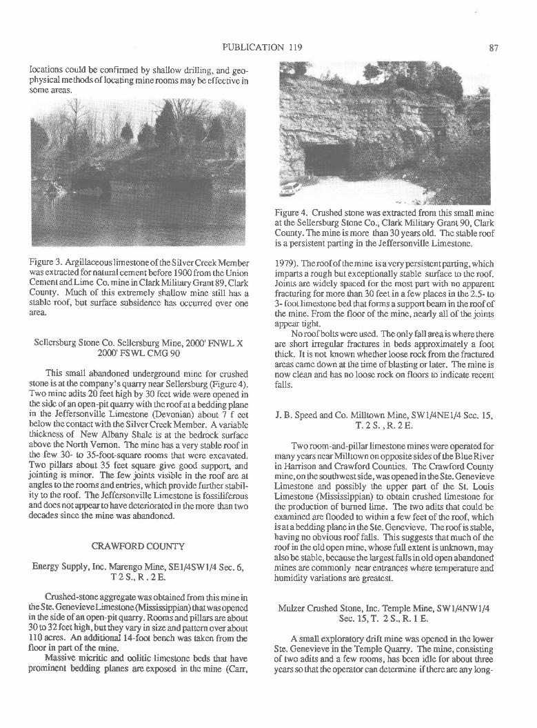
PUBLICATION I19
locations could be conf,rmed by shallow drilling, and geo-physical methods of locating minerooms may be effective insome areas.
Fi gure 3. Argillaceous lim estone of the S ilver Creek Memberwas extracted for natural cement before 1900 from the UnionCement and Lime Co. mine in Clark Military Grant 89, ClarkCounty. Much of this extremely shallow mine still has astable roof, but surface subsidence has occurred over onearea,
Sellersburg Stone Co. Sellersburg Mine,2000'FI.WVL X2000'FswL cMG 90
This small abandoned underground mine for crushedstone is at the company's quarry near Sellersburg (Figure 4).Two mine adits 20 feet high by 30 feet wide were opened inthe side of an open-pitquarry with theroof atabedding planein the Jeffersonville Limestone (Devonian) about 7 f eetbelow the contact with the Silver Creek Member. A variablethickness of New Albany Shale is at the bedrock surfaceabove the North Vernon. The mine has a very stable roof inthe few 30- o 35-foot-squarc rooms that were excavated.Two pillars about 35 feet square give good support" andjointing is minu. The few joints visible in the roof are atangles to the rooms and entries, which provide further stabil-ity to the rmf. The Jeffenonville Limestone is fossiliferousand does not appear to have deteriorated in the more than twodecades since the mine was abandoned.
CRAWFORD COI.JNTY
Energy Supply,Inc. lvlarengo Mine, SEI/4SWI/4 Sec.6,T2S.,R.2E.
Crushed-sone aggregate was obtained from this mine inthe S te. Genevieve Limeslone (Mississippian) that was openedin the side of an open-pitquarry. Roomsandpillars are about30 o 32feethigh, butthey vary in sizeandpatternoveraboutll0 rcrqs. An additional l4-foor bench was taken from thefloor in part of the mine.
lvlassive micritic and mlitic limestone beds that havepromirrcnt bedding planes are exposed in the mine (Can,
Figure 4. Crushed stone was extracted from this small mineat the Sellenburg Sone Co., Clark Military Grant 90, ClarkCounty. The mine is more than 30 years old. The sable roofis a persistent parting in ttre Jeffersonville Limestone.
1979). Theroofof themine isavery persistentparting, whichimparts a rough but exceptionally stable surface to the roof.Joints are widely spaced for tlre most part with no apparentfracturing for more than 30 feet in a few places in the 2.5- to3- footlimestonebed ttratforms a suppoflbeam in theroof ofthe mine. From the floor of the mine, nearly all of the jointsappear tight.
No roof bolts were used. The only fall area is where thereare short irregular frachres in beds approximately a footthick. It is not lnown whether loose rock from the fracturedareas came down at the time of blasting or later. The mine isnow clean and has no loose rock on floors to indicate recentfalls.
J. B. Speed and Co. Milltown Mine, SW1/4NE1/4 Sec. 15,T.2S.,R.28.
Two room-and-pillar limestone mines were operated formany years nearMilltown on oppositesides of theBlueRiverin Harrison and Crawford Counties. The Crawford Countymine, on the southwest side, was opened in the Ste. GenevieveLimestone and possibly the upper part of the St. LouisLimestone (Mississippian) o obtain crushed limeslone forthe production of burned lime. The nvo adis that could beexamined are flmded to within a few feet of the rmf, whichis at a bedding plane in the S te. Genevieve. The roof is stable,having no obvious roof falls. This suggests that much of theroof in the oldopen mine, whose full extent is unlmown, mayalsobe stable, because the largestfalls in old open abandonedmines are commonly near entrances where temperature andhumidity variations are great€st.
Mulzer Crushed Stone,Inc. Temple Mine, SWI/4NW1/4Sec. 15, T. 2 S., R. 1 E.
A small exploratory drift mine was opened in the lowerSte. Genevieve in the Temple Quarry. The mine, consistingof two adits and a few rooms, has been idle for about threeyears so that the operator can determine if there are any long-
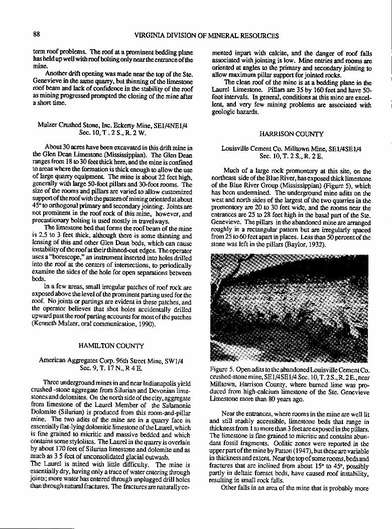
88 VIRGIMA DIVISION OF MINERAL RESOURCES
term rcof problems. The roof at a fominent bedding planehas heldupwell withroof boltingonly nearttreenrancb of themine.
_ Anothq drift opening was made near the top of the Ste.Genevieve in the same quarry, but thinning of the limestoneroof beam and lrck of confidence in the stability of the roofas mining progressedprompted the closing of the mine aftera short time.
Mulzer Crushed Storrc, Inc. Eckerty Mine, SEI/4NE1/4Sec. 10, T . 2 S., R.2 W.
About 30 acres have been excavated in this drift mine inthe Glen Dean Limestone (Mississippian). The Glen Deanranges from 18 to 30 feet thick here, and the mine is confinedto areas where the formation is thick enough o allow the useof large quarry equipmenL The mine is about 22 feothigh,generally with large 50-fmt pillars and 30-foot rooms. fhesize of the rooms andpillan are varied to allow cuslomizedsupport of theroof with thepattern of mining oriented at about45'o orttrogonal primary and secondary jointing. Joints arenot prominent in the roof rock of this mine, however, andprecagtionary bolting is used mostly in travelways.
The limestone bed that forms the roof beam of the mineis 2.5 to 3 feet thick, although there is some thinning andlensing of this and other Glen Dean beds, which can causeinstabilityof theroof attheir ttrinned-out edges. Theoperatoruses a "borescope," an instrument inserted into holes-drilledinto the roof at the centers of intersections, to periodicallyexamine the sides of the hole for open separations benveenbeds.
In a few areas, small inegular patches of roof rock areexposedabove thelevel of the prominentparting used for theroof. No joints u partings are evident in these patches, andthe operator believes ttrat shot holes accidentally drilledupward past ttre roof parting accounts for most of the patches(Kenneth Mulzer, oral communication, 1990).
HAMIL'TON COUNTY
American Aggregate,s Corp. 96th Street Mine, SWI/4Sec. 9, T. 17 N., R 4 E.
Three underground mines in and nearlndianapolis yieldcrushed -stone aggegate from Silurian and Devonian lime-stones and dolomites. On the north side of the city, aggregatefrom limestone of the Laurel Member of the SalamonieDolomitel (Silurian) is produced from this room-and-pillarmine. The nvo adits of the mine are in a quarry faie insssentiail y flat_lying dolomitic limestone of theLaurel, whichis fine grained to micritic and massive bedded and whichcontains somestylolites. Thelaurel in thequarry is overlainby about 170 feet of Silurian limestone and dolomite and asmuch as 3 5 feet of unconsolidated glacial outwash.The Laurel is mined with little difficulty. The mine isgs.sntially dry, having only a trace of water entering throughjoints; more waler has entered through unplugged drill holesthan through natural fractures. The fractures are naturally ce-
mented inpart with calcite, and the danger of roof fallsassociated with jointing is low. Mine entries and rooms areoriented at angles to the primary and secondary jointing toallow maximum pillar support for jointed rocks.
The clean roof of the mine is at a bedding plane in theLaurel Limestone. Pillars are 35 by 160 feet and have 50-foot int8rvals. In general, conditions at this mine are excel-lent, and very few mining problems are associated withgeologic hazards.
HARRISON COUNTY
Louisville Cemenr Co. Milltown Mine, SEI/4SEI/4Sec. 10, T. 2 S., R. 2 E.
Much of a large rock promontory at this site, on thenortheast side of the Blue River, has exposed thick limestoneof the Blue River Group (Mississippian) (Figure 5), whichhas been undermined. The underground mine adits on thewest and north sides of the largest of the two quarries in thepromontory are 20 to 30 feet wide, and the rooms near theentrances ae 25 ta 28 feet high in the basal part of the Ste.Genevieve. The pillars in the abandoned mine are arrangedroughly in a rectangular pa$ern but are irregularly spacedfrom 25 to 60 feet aprt in places. Irss than 50 percent of thestone was left in the pillars (Baylor,1932).
Figure 5. Open adis to theabandonedlnuisvilleCementCo.crushed-stone mine, SE 1/4SE 1/4 Sec. I 0, T. 2 S., R. 2 8., nearMilltown, Harrison County, where burned lime was pro-duced from high-calcium limestone of the Ste. GenevieveLimestone more tlan 80 years ago.
Near the entrances, where rooms in the mine are well litand still readily accessible, limestone beds that range inthickness from I to more than 3 feet are exposed in the pillars.The limestone is fine grained to micritic and contains abun-dant fossil fragments. Oolitic zones were reported in theupper part of the mine by Paton ( 1 947), but these are variablein thickness and extent. Nearttre top of somerooms,beds andfractures that are inclined from about l5o to 45o, possiblypartly in deltaic foreset beds, have caused roof instability,resulting in small rock falls.
Other falls in an area of the mine that is probably more
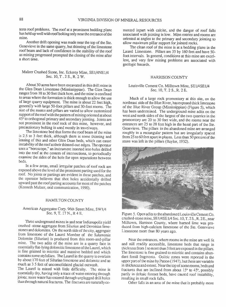
88 VIRGIMA DIVTSION OF MINERAL RESOI.'RCES
lerm rcof problerns. The roof at a p,ominent bedding planehas held up well with roof bolting only near ttre entranc-e of ttremine.
a short time.
Mulzer Crushed Slorrc, Inc. Eckerty Mine, SEI/4N81/4Sec. 10, T . 2 S., R.2 W.
About 30 acres have been excavated in this drift mine inthe Glen Dean Limestone (Mississippian). The Glen Deanranges from l8 to 30 feet thick here, and the mine is confinedto areas where the form allow the useoflarge quarry equipm 22 feethigh,generally with large 50 t rooms. fhesize of the rooms and pillars are varied !o allow customized
preclutionary bolting is used mostly in travelways.The limestone bed that forms the roof beam of the mine
is 2.5 to 3 feet thick, although there is some thinning andlensing of this and other Glen Dean beds, which can causeinstabitty of ttreroof attheir thinned-out edges. The operatoruses a "borescope," an instrument inserted into holesdrilledinto the roof at the centers of intersections, to periodicallyexamine the sides of the hole for open sepantions Uetweenbeds.
In a few areas, small inegular patches of roof rock are
HAMILTON COUNTY
American Aggregates Corp. 96ttr Street Mine, SWI/4Sec. 9, T. 17 N., R 4 E.
Three underground mines in and near Indianapolis yieldcrushed -stone aggrcgate from Silurian and Devonian iime-stones and dolomites. On the norttr side of the city, aggregatefrom limestone of the Laurel Member of the Salamonie
contains some stylolites. The I-aurel in ttre quarry is overlainby about 170 feet of Silurian limesrone and dolomite and asmuch as 3 5 feet of unconsolidated glacial outwash.The Laurel is mined with little difhculty. The mine isessentially dry, having only a trace of water entering throughjoins; more water has entered through unplugged Oritt trotqsthan through natural fractures. The fractures arc naturallv ce-
mented inpart with calcite, and the danger of roof fallsassociated with jointing is low. Mine entries and rmms areoriented u angles to the primary and secondary jointing oallow maximum pillar support for jointed rocks.
The clean roof of the mine is at a bedding plane in theIaurel Limestone. Pillars are 35 by 160 feet and have 50-foot intervals. [n general, conditions at this mine are excel-lent, and very few mining problems are associated withgeologic hazards.
HARRISONCOIJNTY
Iouisville Cement Co. Millown Mine, SEI/4SEI/4Sec. 10, T. 2 S., R. 2 E.
Much of a large rock promontory at this site, on thenortheast side of ttre Blue River, has exposed thick limestoneof the Blue River Group (Mississippian) (Figure 5), whichhas been undermined. The underground mine adits on thewest and north sides of the largest of the two quarries in thepromontory are 20 to 30 feet wide, and the rooms near theentrances arc 25 n 28 feet high in the basal part of the S te.Genevieve. The pillars in the abandoned mine are arrangedroughly in a rectangular pattern but are inegularly spacedfrom 25 to 60 feet apart in places. Irss than 50 percent of thestone was left in the pillars (Baylor,1932).
Figure 5. Open adis to the abandoned Louisville Cement Co.crushed-stone mine, SE l/4SE l/4 Sec. I 0, T. 2 S., R. 2 E., nearMilltown, llarrison County, where burned lime was pro-duced from high-calcium limestone of the Ste. GenevieveLimestone more than 80 years ago.
Near the entrances, where rooms in the mine are well litand still readily accessible,thickness from 1 to more thanThe limestone is fine graineddant fossil fragments. Oolitic zones were reported in theupperpart of the mineby Paton (1947), butrheseare variablein thickness and extent. Near the top of some rooms, beds andfractures that are inclined from about 15" to 45o, possiblypartly in deltaic foreset beds, have caused roof instability,resulting in small rock falls.
Other falls in an area of the mine that is probably more

PUBLICATION 119 89
than 40 years old involve lrins that extend down corridorspast several pillars . Some falls, bordered in part by joints,havedislodgedfrom theroofat bedding planes from less thanone foot o nearly five feet apart vertically @gure 6), al-ttnugh some falls may have involved several beddingplanesatdifferent times. Away from the entrances, tlre largest fallsin the old mine are in areas where the pillars are far apart.Closely spaced ilints have caused small falls in at least onearea One large fall of approximately 12 vertical feet at an
intersection of conidors is bounded in part by prominentjoins.
Figure 6. Roof-fall area near open adits of the abandonedMillown Mine (see Figure 5). In this photograph, falls fromatleastfivebedding planes in ttre Ste. Genevieve areboundedby joints oriented nearly parallel to corridors. Also note thesmall size of the pillar in the foreground.
A large fall of more than 15 feet is exposed at an aditentrance on the southeast side of the promontory. The fallseparated from bedding planes in the Ste. Genevieve, andjoints border parts of ttre fall. Here, the mine is directlyexposed o the climatic changes of the outside air with fresh-aircirculation through this and other nearby connecting adits.The changes in temperature and humidity in the mine are thusparticularly severe in this area, which may account in part forthe large fall. It should be noted that no roof bols were usedin this mine; roof bolts did not come into common use in coalmines until after World War II @enver Harper, oral communication, 1989), and their widespread use in limestone mines
was probably no earlier,The durability and good condition of many parts of the
old mine indicate ttrat if properly spaced and oriented pillarshadbeen usedandifrmf bolts couldhavebeen used when themine was operating, most of the mine would still be in as goodcondition as when it was opened.
Because ttre limesone from the mine was used forbumed lime, it was important to the company that the stonebe low in magnesium, and chemical analyses of samples ofthe Ste. Genevieve Limestone at this location by the IndianaGeological Survey shows an average MgCO, of less ttran 2percent where sampled. But the percentage of MgCO, inlimestone varies, and at least part of the reason for theabandonment of the mine, according to Dennis Sarels, a 35-year employee at the mine, was an increase in magnesium in
parts of the mine (oral communication, 1970). Mr. Sarelsalso
said that "soapstone" (probably shaly limestone or shale) was
encounlered and conributed to the decision to close the mine.
LAWRENCE COIJNTY
Mitchell Crushed Stone Co. Mitchell Mine, NE1/4SW1/4Sec. 12, T. 3 N., R. 2 W.
ThenvoadisofttrisabandonedmineintheSte. Genevieve
arc 28 feet high, and the mine is partially flooded. The mine
was operated for a short time in 1963 until a large section ofthe roof about 8 feet thick fell during an idle shift, and the
mine was then abandoned. Mr. Lee Powell (oral communi-cation, 1989), superintendent of the operation, believes thatthin shale bands in the limestone above the mine were the
prohble main cause of the fall and made the operation toodangerous to continue. Roof bolts were used extensively inthe hine but were ineffective in places according to Mr.Powell. The entrance to the mine, which is heavily bolted, has
held up well.
Elliott Sone Co., Inc. Eureka Mine, NE1/4SW1/4 Sec. 18,
T5N.,R.lW.
Dimension limestone is mined from the Salem Lime-stone (Mississ ippian) in an underground room, 80 feet wideand 30 o 35 feet high, in the face of a dimension-stone quarry
nearEureka (Figqre 7). The rough roof ataprominentpartingin the Salem is very stable. Precautionary roof bolting i s used
routinely. Joints in the Salem at this mine are spaced as far
apart as 200 feer The few joints that were observed at thismine appear to be well cemented for the most part and
apparently pose little danger of rock falls. Long rib pillars are
used to keep jointed rocks well supported' One side of the
mine room excavated thus far is at a prominent joint, givingan irregular side to the dimension-stone blocks removed fromttr,at part of the mine.
MADISON COUNTY
Martin Marietta Aggregates Corp. Lapel Mine, NEl/4NWl/4 Sec. 2 8, T. 19 N.,R. 6 E.
Crushed-stone aggegate was produced from this aban-
doned under ground mine at Lapel. The mine was opened inthe north quarry face of an open-pit mine in flatJying louis-ville Limeione (Silurian) at the edge of tilted flank beds ofa reef of the Wabash Formation (S ilurian). Rooms and pillarsare about 40 by 40 feet wide. The rooms are 23 feet high, and
a second bench, also 23 feet high, was removed from part ofthe floor of the mine before it was abandoned. Scaling crews
helped clear loose rock from theroof and pillars, but the tiltedbeds of the reef caused some difficulties in roof control and
mining operations where they were encountered (Glen
Campheld, oral communications, 1989). The mine is now
completely flooded.
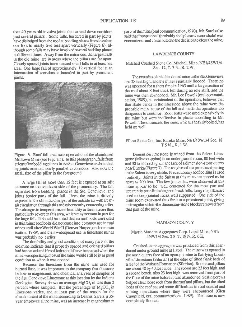
PUBLICATION 119 89
than 40 years old involve joints that extend down corridorspast several pillars . Some falls, bordered in part by joins,have dislodged from theroof at bedding planes from less thanone foot to nearly five feet aprt vertically (Figure 6), al-though some falls may have involved several beddingplanesat different times. Away from the entrances, the largest fallsin the old mine are in areas where the pillars are far apart.Closely spacedirins have caused small falls in at leastonearea One large fall of approximately 12 vertical feet at anintersection of conidors is bounded in part by prominentjoints.
Figure 6. Roof-fall area near open adits of the abandonedMilltown Mine (see Figure 5). In this photograph, falls fromatleastfivebedding planes in the Ste. Genevieve areboundedby joints oriented nearly parallel o corridors. Also note thesmall size of the pillar in the foreground.
A large fall of more than 15 feet is exposed at an aditentrance on the southeast side of the promontory. The fallseparated from bedding planes in the Ste. Genevieve, andjoins border parts of the fall. Here, the mine is directlyexposed to the climatic changes of ttre outside air with fresh-aircirculation through this and otlrer nearby connecting adis.The changes in temperature and humidity in the mine are thusparticularly severe in this area, which may account in part forthe large fall. It should be noted that no roof bols were usedin this mine; roof bolts did notcome into common use in coalmines until after World War II @enver I{arper, oral communication, 1989), and their widespread use in limestone mineswas probably no earlier.
The durability and good condition of many parts of theold mine indicate that if properly spaced and oriented pillarshad been used and if rmf bols could have been used when themine was operating, most of the mine would still be in as goodcondition as when it was opened.
Because the limestone from the mine wa.s used forburned lime, it was important to the company that the stonebe low in magnesium, and chemical analyses of samples oftlre Ste. Genevieve Limestone at this location by the IndianaGeological Survey shows an average MgCO, of less than 2percent where sampled. But the percentage of MgCO, inlimeslone varies, and at least part of the reason for theabandonment of the mine, according to Dennis Sarels, a 35-year employee at the mine, was an increase in magnesium in
parts of the mine (oral communication, 1970). Mr. Sarelsalso
said that "soapstone" (probably shaly limestone or shale) was
encountered and conributed to the decision !o close the mine.
LAWRENCE COUNTY
Mirchell Crushed Stone Co. Mirchell Mine, NEI/4SW1/4Sec. 12,T.3 N.,R.2W.
The nro adits of ttris abandoned mine in the S te. Genevieve
are 28feet high, and the mine is partially flooded. The minewas operated for a short time in 1963 until a large section ofthe roofabout 8 feet thick fell during an idle shift, and themine was then abandoned. Mr. Lee Powell (oral communi-cation, 1989), superintendent ofthe operation, believes thatthin shale bands in the limestone above the mine were theprobable main cause of ttre fall and made the operation too
dangerous to continue. Roof bols were used extensively inthe mine but were ineffective in places according to Mr.Powell. The entrance !o the mine, which is heavily bolted, has
held up well.
Elliott Stone Co., Inc. Eureka Mine, NEI/4SWI/4 Sec. 18,
T5N.,R. lW.
Dimension limestone is mined from the Salem Lime-stone (Mississ ippian) in an underground room, 80 feet wideand 30 o 35 feet high, in the face of a dimension-stone quarrynearEureka (Figure 7). The rough roof ataprominentpartingin the Salem is very stable. Precautionary roof bolting i s used
routinely. Joints in the Salem at this mine are spaced as farapart as 200 feet" The few joints that were observed at thismine appear to be well cemented for the most part and
apparently pose little danger ofrock falls. Long rib pillars are
used to keep jointed rocks well supported. One side of themine room excavated thus far is at a prominent joint, givingan irregular side o the dimension-stone blocks removed fromthat part of the mine.
MADISON COUNTY
Martin Marietta Aggregates Corp.Iapel Mine, NEl/4NW1/4 Sec. 2 8, T. 19 N.R. 6 E.
Crushed-stone aggregate was produced from this aban-
doned under ground mine at Iapel. The mine was opened inthe north quarry face of an open-pit mine in flat-lying Louis-ville Limestone (Silurian) at the edge of tilted flank beds ofa reef of the Wabash Formation (S ilurian). Room s and pillarsare about 40 by 40 feet wide. The rooms are 23 feet high, and
a second bench, also 23 feet high, was removed from part ofthe fl oor of the mine before it was abandoned. Scaling crews
helped clear loose rock from the roof and pillars, but ttte tiltedbeds of the reef caused some difficulties in roof control and
mining operations where they were encountered (Glen
Campheld, oral communications, 1989). The mine is nowcompletely flooded.
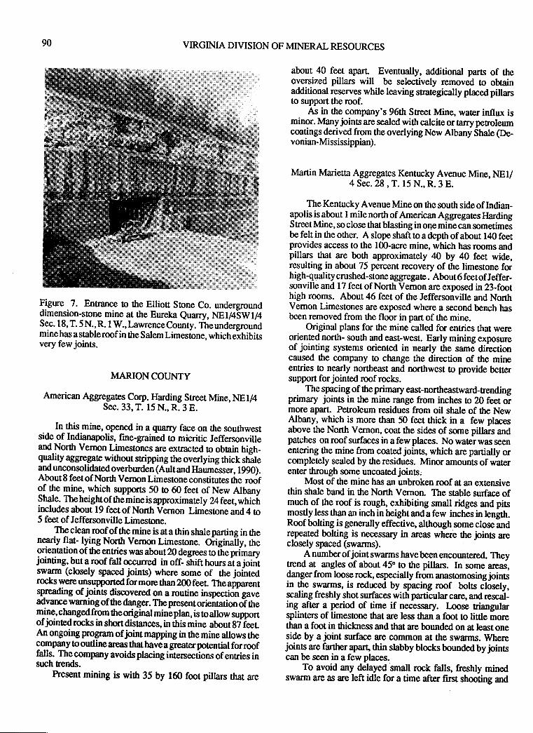
90 VIRGINIA DIVISION OF MINERAL RESOURCES
Figure 7. Entrance o the Elliou Stone Co. undergrounddimension-srone mine at the Eureka euarry, Ngt/+SWt/+Sec. I 8, T. 5 N., R. 1 W., Lawrence County. The undergroundmine has a stableroof in the Salem Limestone, which exhibisvery few joints.
MARION COUNTY
American Aggregates Corp. Ilarding Street Mine, NE1/4Sec. 33, T. 15 N., R. 3 E.
In this mine, opened in a quarry face on the southwestside of Indianapolis, fine-grained to micritic Jeffersonvilleand North Vernon Limestones are exmcted to obtain high-quality aggregate without sripping ttn overlying thick sh-aleand unconsolidated overburden (Aultand llaumesser, 1990).About 8 feet of North Venron Limestone constitutes the roofof the mine, which- supports 50 to 60 feet of New AlbanyStnle. Theheightof themineis approximately Z feet, whicfiincludes about 19 feetof North Vbrnon Limestone and4 to5 feet of Jeffersonville Limesone.
Theclean roof of the mine is ata thin shaleparting in ttrenearly flat- lying North Vernon Limesone. Original'ly, theorientrtion of theentries was about20degrees to theprimaryjointing, but a roof fall occurred in off- shift hours at ajointswarm (closely spaced.i<rints) where some of the lointedrocks were unsupported for more than 200 feet. The apparentspreading of lrinc_discovered on a routine inspection gaveadvance warning of the danger. The present orientation oT ttremjlg,changedfrom heoriginal mineplan, is toallow supportofjointed rocks in short distances, in this mine about g7 feerAn ongoing program ofjoint mapping in ttre mine allows thegornpany Eo outline areas that have a greater potential for rooffalls. Thecompany avoids placing intenections of entries insuch trends.
Present mining is with 35 by 160 foot pillars that are
about 40 feet apart Eventually, additional pars of theoversized pillars will be selectively removed lo obtainadditional reserves while leaving srategically placed pillarsto support the roof.
As in the company's 96th Sreet Mine, water influx isminor. Many joints are sealed with calcite or tarry peroleumcoatings derived from the overlying New Albany Shale (De-vonian-Mississippian).
Martin Marietta Aggregates Kentucky Avenue Mine, NEI/4 Sec.28, T. 15 N., R.3 E.
The Kentucky Avenue Mine on the south side of Indian-apolis is about I mile north of American Aggregates llardingStreet Mine, so close that blasting in o4e mine can sometimesbe felt in the ottrer. A slope shaft to a depth ofabout 140 feetprovides access to the 100-acre mine, which has rooms andpillars that are both approximately 40 by 40 feet wide,resulting in about 75 percent recovery of the limestone forhigh-quatity crushed-stone aggregata. About6 feetofJeffer-sonville and 17 feet of North Vemon are exposed in 23-foothigh rooms. About 46 feet of the Jeffersonville and NorthVemon Limestones are exposed where a second bench hasbeen removed from the floor in part of the mine.
Original plans for the mine called fon entries that wereoriented north- south and east-west. Early mining exposureof jointing systems oriented in nearly the same directioncaused the company to change the direction of the mineentries o nearly northeast and northwest o provide bettersupport for jointed roof rocks.
. The spacing of theprimary east-northeasnvard-rendingprimary joints in the mine range from inches o 20 feet oimore apart. PeEoleum residues frOm oil shale of the NewAlbany, which is more than 50 feet rhick in a few placesabove the North Vernon, coat the sides of some pillars andpatches on roof surfaces in a few places. No water was seenentering the mine from coated joints, which are partially orcompletely sealed by the residues. Minor amounts of waterenter through some uncoated joints,
Most of the mine has an unbroken roof at an extensivethin shale band in the North Vernon. The stable surface ofmuch of the roof is rough, exhibiting small ridges and pitsmostly less than an inch in height and a few inches in length.Roof bolting is generally effective, although some close andrgpealed bolting is necessary in areas wherb the joints areclosely spaced (swarms).
A number ofjoint swarms have been encounlered. Theytrend at angles of about 45" to the pilla$. In some areas,danger from loose rock, especially from anastomosing jointsin the swarms, is reduced by spacing roof bolrs closely,scaling freshly shot surfaces with particular care, and rescal-ing after a period of time if necessary. Ioose riangularsplinters of limestone that are less than a foot to little morethan a foot in thickness and that are bounded on at le,ast oneside by a joint surface are common at the swarms. Wherejoints are farther apart, thin slabby blocks bounded by jointscan be seen in a few places.
To avoid any delayed small rock falls, freshly minedswarm are as are left idle for a time after frst shooting and

90 VIRGINIA DIVISION OF MINERAL RESOURCES
Figure 7.dimensionSec.18,T.minehasavery few joins.
MARION COUNTY
American Aggregates Corp. tlarding Street Mine, NEI/4Sec. 33, T. 15 N., R. 3 E.
In this mine, opened in a quarry face on the southwestside of Indianapolis, fine-grained o micritic Jeffersonville
5 feet of Jeffersonville Limestone.
An ongoing program oflrint mapping in the mine allows thecompany to outline areas that have a grealer potential for rooffalls. The company avoids placing intenections of entries insuch trends.
hesent mining is wittr 35 by 160 foot pillan rhar are
about 40 feet apart Eventually, additional parts of theoversized pillars will be selectively removed to obtainadditional reserves while leaving strategically placed pillarsto support the roof.
As in the company's 96th Sreet Mine, water influx isminor. Many joinb are sealed with calcite or tarry petroleumcoatings derived from the overlying New Albany Shale (De-vonian-Mississippian).
Martin Marietta Aggregates Kentucky Avenue Mine, NEI/4 Sec.28, T. 15 N., R.3 E.
The Kentucky Avenue Mine on the south side of Indian-apolis is about I mile north of American Aggegates }lardingS treet Mine, so close ttrat blasting in o4e mine can sometimesbe felt in the other. A slope shaft to a depttr of about 140 feetprovides access to the 100-acre mine, which has rooms andpillars Orat are both approximately 40 by 40 feet wide,resulting in about 75 percent recovery of the limestone forhigh-quality crushed-srone aggegat€ . About 6 feet of Jeffer-sonville and 17 feet of North Vemon are exposed in 23-foothigh rooms. About 46 feet of the Jeffersonville and NorthVernon Limestones are exposed where a second bench hasbeen removed from the floor in part of the mine.
Original plans for the mine called for entries that wereoriented north- south and east-west. Early mining exposureof jointing systems oriented in nearly the same directioncaused the company to change the direction of the mineentries to nearly northeast and northwest to provide bettersupport for jointed roof rocks.
The spacing of the primary east-northeasnvard-rendingprimary joints in the mine range from inches o 20 feet ormore apart. Petroleum residues from oil shale of tlre NewAlbany, which is more than 50 feet thick in a few placesabove the North Vemon, coat the sides of some pillars andpatches on roof surfaces in a few places. No water was seenentering the mine from coated joints, which are partially orcompletely sealed by the residues. Minor amounts of waterenter through some uncoated joints.
Most of the mine has an unbroken roof at an ext€nsivethin shale band in the Norttr Vernon. The stable surface ofmuch of ttre roof is rough, exhibiting small ridges and pitsmostly less than an inch in height and a few inches in lengltr.Roof bolting is generally effective, alttrough some close andrepeated bolting is necessary in areas where the joins areclosely spaced (swarms).
A number ofjoint swarms have been encountered. TheyEend at angles of about 45" to the pillan. In some areas,danger from loose rock, especially from anasomosing jointsin the swarms, is reduced by spacing roof bols closely,scaling freshly shot surfaces with particular care, and rescal-ing after a period of time if necessary. I-oose riangularsplinters of limestone tlrat are less than a foot to little morethan a foot in thickness and that are bounded on at least oneside by a joint surface are common at the swarms. Wherejoints are farther apart thin slabby blocks bounded byjoinscan be seen in a few places.
To avoid any delayed small rock falls, freshly minedswarm are as are left idle for a time after first shooting and
PUBLICATION 119 9r
bolting. As in the American Aggregates mine a short distancesouthward, the swarms tend to stay on nend with the majorjoint directions, but the ex[ent of individual swarms alongnend is unpredictable. But the prediction of the direction ofthe swarms, if not their extent, allows extra caution to be taksnalong the swarm trends as mining proceeds.
Fein (1983) indicated that blast damage in the roof rockwas also the cause ofroof falls in this mine,particularly wherethe roof sloped in the direction of mining.
MONROE COUNTY
Hoosier Calcium Corp. Gosport Mine, SEI/4NW1/4 Sec.20, T. 10 N., R. 2 W.
High-calcium limestone crushed for glass flux is pro-duced from an underground mine in the Salem Limestonenear Gosport The mine occupies about 12 acres with rooms45 to 50 feet wide and pillars 50 to 55 feet square. The rooms,which are mined in a roughly rectangular pattern orientedeast-west, are 25 to 30 feet high, and a small part of ttre minehas a floor bench removed to a depth of about 12 feet.
The roof of the mine is at or near the contact between thefine- to medium-grained Salem Limestone and the overlyingfine-grained to nearly micritic St. Louis Limestone. Al-though much of the mine roof appears stable ataparting in theSalem, fractures and inclined bedding in the upper beds of theSalem and in the basal Sr Louis have caused roof problemsin pars of the mine. The fractures appear to trend nearly east-west in part but are irregular and allow some unstable roofconditions, particularly at the thinned-out edges of someinclined beds. Roof bolting has been used only at the mineentrance thus far.
ORANGE COI.JNTY
Calcar Quanies, Inc. Paoli Mine, SEl/4SEli4 Sec. 6, T. IN., R. I E.
At this operation near Paoli, a one-room undergroundmine in the Ste. Genevieve Limestone is used as a shop forservicing equipment for the quarry operation. The roof at aprominent bedding plane has been bolted and appears stable.
PERRY COI]NTY
Mulzer Crushed Stone,Inc. Derby Mine, SE1/4SEI/4 Sec.32,T.5 S.,R. I W.
About 5 acres of the upper part of ttre Ste. GenevieveLimestone was minedhere forcmshed-stone aggregate. Thinshale partings in the roof rock caused some rmf falls and theneed forclosely sprced roof bolts. Corrosion of the roof boltsby seeps of acidic waterwas alsoaproblem (Kennettr Mulzer,oral communication, 1990).
Mulzer Crushed Stone,Inc. Derby Mine, NW1/4SEI/4Sec. 32, T. 5 S., R. 1 W.
A room-and-pillar mine of about 5 acres w:ls operatedhere for about 4 years in the llaney Limestone (Mississip-pian). The Haney contains ttrin limestone beds and shalypartings, which required roof bolts for roof control duringmuch of the operation of the mine. Mining in other stratigra-phic positions in the Haney was attempted, but the need forroof bolts made the operations overly expensive for crushed
stone.
Conex,Inc. Derby Mine, SWl/4NEl/4 Sec 32, T. 5 S.,R. 1W.
This 25-acre drift mine in the Glen Dean Limestone wasoriginally operated by Mulzer Crushed Stone for crushed-stone agglegate. Rooms are about 20 fent high near the
entrance, and rooms and pillars vary in width, some beingmore than 30 feet long. Extra large pillars were left routinely.Where observed in the mine, jointing is widely spaced andonly slightly developed. No roor falls are associated withjointing that was examined near the entrance. Rooms andpillars are oriented at abut4Sto45"to whatlittle jointing ispresenL
Roof bolting near the entrance was used to help controla thin limestone bed that ranges from less than 2 inches tonearly a foot ttrick and which has remained securely in place
since shortly after the mine was opened . The overlyinglimestone bed forming most of the roof in the mine stillappearc quite stable over a large area near the entrance.Kenneth Mulzer (oral communication, 1990) reported thatthe roof rock deeper in the mine was also stable during activeoperations.
The Glen Dean Limestone does not maintain a consistentthickness, and usable reserves were limited. The necessityfor useof large quarry equipment in theGlen Deanpresentedproblems with a shaly floor and a thin limestone roof inplaces. These were the main factors that caused the companyto stop underground crushed-stone operations.
Conex, Inc. now uses a few rooms near the front of themine to store explosives and equipment
DISCUSSION
Rooney and Carr (197I) discussed ttle advantages and
disadvantages of mining industrial limestone undergroundincluding ttre advantage of selective mining to obtain particu-lar beds. This is a major factor for all of the active mines inIndiana as it was for most of the abandoned mines. NearIndianapolis, sources of limestone and dolomite for high-quality crushed-stone aggregate are either overlain by car-
bonate rock of lesser quality or are overlain by thick shale and
unconsolidated overburden, which are ttre main reasons the
three active underground mines at Indianapolis were opened.Protection ftom the weather and confinement of environ'mental problems underground are lesser facors that make theoperations of these mines atrractive.
92 VIRGIMA DIVISIOI
The nvo active underground mines in ttre Salem Lime-slone, Elliott Soone's dimension-sone mine in lawrenceCounty and Hoosier Calcium's flux stone mine in MonroeCounty, were opened o exploit the Salem's distinctive quali-ties as a source of dimension sone and for its chemical purityfor glass flux. Other important facors confibuting to thedecisions to open the mines were the ability to mine dimen-sion sorn throughout the year, the preserrce of thick overbur-den at one location (Figue 7), and the ability to minechemically pure fluxstone without surface contamination.Two geologic facors are by far the most importantfor the safeand economic design of the shallow mines. Bed thicknessesard jointing conditions in the rmf rock determine the stabilityof the roof and the potential for roof falls, which is the singlemost hazardous and expensive problem that can occur in anunderground limes0one mine. If mine desrgn and mineoperations take these conditions inlo account, undergroundmining of shallow carbonate rock in Indiana can be highlysuccessful. These factors are of great importance in all of theformations that were or are mined in Indiana. The softestrock mined is probably the Salem Limestone, and jointingand bedding are as important in this formation as in the hardand brittle fine -grained to micritic beds of other formations.
In all of the mines that could be examined, primaryjointing directions are generally east-northeasterly and sec-ondary joints are north-northwesterly, following regionalpatt€rns. Where the primary joins are far apart (20 feet ormore) and well cemented, roof conditions are excellent andsmall falls are rare. Commonly, no rmf bolting is necessaryunder these conditions. Where joints are close together,particularly in swarms (inches o less than about two feetapart), roof falls are a distinct possibility, andprecautions areneeded. Roof bolting is necessary in most places whereswarms occur, but even roof bolting is not always or every-where successful.
Additional precautions that may help control roof condi-tions where swarms are present include:1) orienting the mine at acute angles to ttre orttrogonal jointingto give maximum support to jointed rocks in short distances(as opposed to having prominent jointing parallel to andalong curidors),2) allowing closely jointed rocks to set for a sufficient periodof time to allow for small falls that may occur immediatelyafter mining, 0ren rescaling and rebolting,3) leaving long pillars under and completely across swarmtrends orkeeping long rib pillars entirely under swarms (noteasily accomplished because the length of swarms are diffi-cult to predict),4) and keeping entry intersections away from the swannEends as much as possible.
In some of the old abandoned mines, even where jointingis widely spaced and mostly tightly cemented, roof fallsbounded by joints occur where primary jointing runs downlong corridors past several pillars. Poor roof conditions areexacerbated in the mines where pillars are small.
The second of the two most important geologic factors,thin bedding in the roofrock, caused the closure ofat least oneunderground operation and probably was a contributingfacor in the closing of others. The carbonate roof be4m, thelowermost bed that forms the roof of the mine, is at least 2.5
VIRGIMA DIVISION OF MINERAL RESOURCES
!o 3 feet thick in all of Indiana mines with sable roofs.Because all of the mines in Indiana are less ttran 200 feet fromthe bedrock surface and most are less than 100 feet, thestrength of theroof beams for these shallow mines may notbesufficient for deeper mines. No durability or srength tesswere performed in this study.
Some bedding separations are at thin shale laminationsor at stylolites; other separations appear o be cemented bycalcite o the bed above. It was not determined what effectdifferent conditions at bedding separations have on roofstability, but intuitively it would seem that ttre tighter thebond between beds fte better.
Limestone and dolomite roof beds that ttrin over the largeareas of some mines present a hazard that may not be easilydetected. The thin edges of such beds make for an unsableroof that may require roof bolting. As mentioned above, oneoperator, MulzerCrushed Stone,looks forthin roof beds andopen separations between beds by drilling holes into 0re roofat mine intersections and by using an optical instrument toexamine the sides of the hole.
Some roof falls in abandoned mines involve both thinbeds and poorly supported jointed rocks. This was prticu-larly noticeable at the abandoned Millown Mine in llarrisonCounty. Here at least one and probably several falls occurredat the same place in the mine at separations between thin bedsthat occur on top of each other. Some falls are also boundedbyjoints in rocks that are not supported for long distances bypillars. An addirional cause for some of the falls, mentionedabove in the mine descriptions, may be the varying tempera-tures and humidities that occur in old open mines. Roofbolting would undoubtedly have prevented many falls.
Inclined bedding and fracturing within essentially flat-lying beds, especially where such beds are at or near the roofof a mine, may allow small falls, and such beds may not bedetected until the mine has been opened If possible, the mineroof should be raised or lowered !o other partings to helpcontrol falls.
Facies changes, particularly where clay content or shaleincreases in a limesone mine, are obviously unfavorable. Soare increases in magnesium in mines that are being used as asource of high-calcium limestone. Color changes, texturalchanges, or an increase in the number of stylolites in adimension-stone mine are also detrimental. Here again, aclosely controlled exploratory drilling prograrn can detectmany of these conditions before mining stars.
The underground mining of Silurian reef rock, present ina small part of the abandoned underground mine at lapel,Madison County, has not been attempted elsewhere in Indi-ana, although much high-quality reef rock is quanied fromopen pits in north-central Indiana. The steeply tilted flankbeds in the generally dome-shaped reefs present operationalmining problems that will have to be overcome to makeunderground mining practical in the reefs.
As faras is known, waterinflux into the shallow Indianamines has not been much of a problem. Small amounts entersome mines through open joints, but many joints are ce-mented by calcite or, in tle case of mines in limestone beneaththe New Albany oil shale, sealed with petroleum residues.
Because many of the underground mines in Indiana areso shallow , the danger of surface subsidence would appear to
PUBLICATION 119 93
be grear Surprisingly, it was found that nearly all of themines in Indiana, active or abandoned , are stable for the mostpart with surface subsidence caused by hazardous geologicconditions occurring in only a few places. It was alsoapparent that even where mines had been abandoned formany years and some roof falls had occurred, the worst fallshad worked up through not more than 10 to 15 feet ofcarbonate rock This speaks well for the stability of the oldmines and for the environmental safety of active and futuremines.
In the most extensive area of surface subsidence known(approximately 7 acres in Clark County), a pre-1900 mine isin extremely shallow bedrock, probably less thick than theheight of the mine itself. Other old mines in this area may beat similar shallow depths, and where these conditions arepresent, surface subsidence is still a hazard.
CONCLUSIONS
Most of the 28 underground limestone and dolomitemines in Indiana were opened to exploit particular beds as analternative for open-pit mining where removal of thick over-burden is economically prohibitive on where overlying mate-rials are marketed more slowly than the materials minedunderground. Other, but less significant reasons, includeyear-round production because ofprotection from adveneweather conditions, confinement of undesirable environ-mental conditions underground, and protection of chemicalstone from surface contamination.
Generally, the mines have or have had good operatingconditions with mostly stable roofs, many of which do notrequire roof bolting. T here is very little water influx in activemines, and all except a few extremely shallow abandonedmines havelong-term resistance to surface subsidence. Care-ful planning of mine design and mine operations furtherenharrce the safe and economic operations of the activemines.
The two most important geologic factors that have af-fected the mines are jointing and bedding conditions in theroofrock. Jointing orientation and spacing andbed thiclnessin carbonate roof rock determine in large part the stability ofthe roof, the need for roof bolting, and the likelihood ofsurface subsidence in extremely shallow mines. Other fac-tos that affect the mines include variable thicknesses of roofbeds resulting in very thin or feather-edge roof beams in partsof some mines; overall thinning of some minable rock unitslimiting minable reserves; inclined bedding and fracturing insome rock units; facies changes, particulady increases ofmagnesium content in high-calcium limestone mines andirrcreases in clay or shale in other mines; and steeply tiltedflankbeds in reef rock.
Some effective measures ttnt can be taken o anticipateand reduce hazards in shallow mines in Indiana includesufficient exploratory and development test drilling, orienta-tion of mines to support unstable roof rock, strategic place-ment of large pillars to help support jointed rocks , and roofbolting in hazardous areas.
REFERENCES CITED
Ault, C. H., 1988, Cause and effect of jointing in quarries incentral and northern Indiana, iz Colton, G. W., ed, Proceed-
ings of the 22nd Forum on Geology of Indusuial Minerals:Arkansas Geological Commission Miscellaneous Publica-tions MP-21, p.17-29.
Ault, C. H., 1989, Map of Indiana showing directions ofbedrock jointing: Indiana Geological Survey MiscellaneousMap52.
Ault, C. H., 1990, Directions and characteristics of jointing
in theNew Albany Shale (Devonian-Mississippian) of south-
eastern Indiana, in hoceedings, 1989 Eastern Oil Shale
Symposium, Institute for Mining and Mirerals Research,
I:xington, Kenurcky, p. 239'252.
Ault, C. H., and Haumesser, A. F., 1990, A central Indianamodel for predicting jointing characteristics in undergroundlimestone mines, in Proceedings of the 24th Forum on theGeology of Industrial Minerals: South Carolina GeologicalSurvey, Columbia, SC, P. 1-8.
Baylor, H. D., 1932, Method and cost of quarrying limestoneat the Mill town quarry of the l,ouisville Cement Company:U.S. Bureau of Mines Information Circular 6603,9 p.
Carr, D. D., 1979, Marengo Mine: Open-file MemorandumRepott, Industrial Minerals Sectiou Indiana GeologicalSurvey, 3 p.
Carr, D. D., and Ault, C. H., 1983, Potential for deep under-ground limestone mining in Indiana: American Instiurte ofMining, Metallurgical, and PeEoleum Engineers Transac-tions, v. 772, p. 1912-1916.
Engelder, Terry,1982, Is there a genetic relationship be-
tween selectedregional joins andcontemporary stress withinthe litlrosphere of North America?: Tectonics, p. 16l-177.
Fein, M. R., 1983, An engineering geology investigation ofan undergtound limestone mine, Indianapolis, Indiana (un-published M.S. thesis): West l-afayette, Purdue Univenity,170 p.
Gray, H. H., Ault, C. H., and Keller, S. J., 1987, Bedrockgeologic map of Indiana: IndianaGeologica I Survey Miscel-laneous Map 48.
Patton, J. B., 1 947, Milltown Mine: Open-fi le MemorandumRepott, Industrial Minerals Section, Indiana GeologicalSurvey, 2 p.
Rooney, L. F., and Carr, D. D.,1971, Applied geology ofindustrial limestone and dolomite: Indiana Geological Sur-vey Bulletin 46,59 p.
Siebenthal, C. 8., 1901, The Silver Creek hydraulic lime-stone of southeastern hdiana: Indiana Department of Geol-ogy and Natural Resources, Annual Report 25, p. 331-389.

94 VIRGINIA DIVISION OF MINERAL RESOURCES
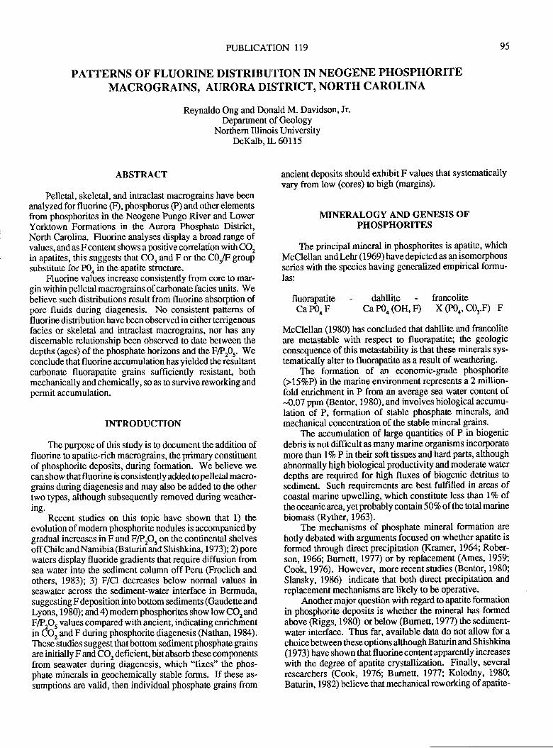
PUBLICATION 119
PATTERNS OF FLUORINE DISTRIBUTION IN NEOGENE PHOSPHORITEMACROGRAINS, AURORA DISTRICT, NORTH CAROLINA
Reynaldo Ong and Donald M. Davidson, Jr.Department of Geology
Northern Illinois UniversityDeKalb,IL 60115
95
ABSTRACT
Pelletal, skeletal, and intraclast macrograins have beenanalyzed for fluorine (F), phosphorus @) and other elementsfrom phosphorites in the Neogene Pungo River and LowerYorktown Formations in the Aurora Phosphate District,Nortlr Carotna. Fluorine analyses display a broad range ofvalues, and as F content shows a positive conelation with CQin apatites, this suggests that CO, and F or the C0r/F $oupsubstitute for P0" in the apatite structure.
Fluorine values increase consistently from core to mar-gin within pelletal macrograins of carbonate facies units. Webelieve such distributions result, from fluorine absorption ofpore fluids during diagenesis. No consistent patterns offluorine distribution have been observed in either terrigenousfacies or skeletal and intraclast macrograins, nor has anydiscemable relationship been observed to date between thedepths (ages) of ttre phosphate horizons and the F/PrOr. Weconclude that fluorine accumulation has yielded the resultantcarbonate fluorapatite grains sufficiently resistant, bottlmechanically and chemically, so as !o survive reworking andpermit accumulation.
INTRODUCTION
The purpose of this study is to document ttre addition offluorine to apatite-rich macrograins, ttre primary constituentof phosphorite deposits, during formation. We believe wecan show that fl uorine is consistently added to pelletal macro-grains during diagenesis and may also be added to the othertwo types, although subsequently removed during weather-ing.
Recent studies on this topic have shown that 1) theevolution of modern phosphorite nodules is accompaniedbygradual increases in F and F/Pp, on the continental shelvesoff ChileandNamibia (Baturin and Shishkina, 1973);2) porewaters display fluoride gradients that require diffusion fromsea water into the sediment column off Peru (Froelich andothers, 1983); 3) F/Cl decreases below normal values inseawater across the sediment-water interface in Bermuda,suggesting F deposition into bottom sediments (Gaudette andLyons, 1980); and 4) modem phosphorites show low CO, andF/PPs values compared with ancient, indicating enrichmentin CO, and F during phosphorite diagenesis (Nathan, 1984).These studies suggest that bottom sediment phosphate grainsare initially F and CQ deficient, birt absorb these componentsfrom seawater during diagenesis, which "fixes" the phos-phate minerals in geochemically stable forms. If these as-
sumptions are valid, then individual phosphate grains from
ancient deposits should exhibit F values that systematicallyvary from low (cores) o high (margins).
MINERALOGY AND GENESIS OFPHOSPHORITES
The principal mineral in phosphorites is apatite, whichMcClellan andl-ehr (1969) have depicted as an isomorphousseries with the species having generalized empirical formu-las:
fluorapatite-dahllite-francoliteCa P0. F Ca POo (OH, D X (P04, C03.F) F
McClellan (1980) has concluded that dahllite and francoliteare metastable with respect to fluorapatite; the geologicconsequence of this metastability is that these minerals sys-
tematically alter to fluorapatite as a result of weatlering.The formation of an economic-grade phosphorite
(>lSVoP) in the marine environment represents a 2 million-fold enrichment in P from an average sea water content of-0.07 ppm (Bentor, 1980), and involves biological accumu-lation of P, formation of stable phosphate minerals, andmechanical concentration of the stable mineral grains.
The accumulation of large quantities of P in biogenicdebris is not difficult as many marine organisms incorporatemore than lVoP ntheir soft tissues and hard parts, althoughabnormally high biological productivity and moderate waterdepths are required for high fluxes of biogenic detritus tosedimenl Such requirements are best fulfilled in areas ofcoastal marine upwelling, which constitute less than l%o oftlre oceanic area, yet probably contan 501oof the total marinebiomass S.yther, 1963).
The mechanisms of phosphate mineral formation are
hotly debated with arguments focused on whether apatite is
formed through direct precipitation (Kramer, 1964; Rober-son, 1966; Burnett, L977) or by replacement (Ames, 1959;
Cook, 1976). However, more recent studies (Bentor, 1980;
Slansky, 1986) indicate that both dfuect precipitation andreplacement mechanisms are likely to be operative.
Another major question with regard to apatite formationin phosphorite deposits is whether the mineral has formedabove (Riggs, 1980) or below (Burne[, 1977) the sediment-water interface. Thus far, available data do not allow for achoice between these options although Baturin and S hishkina(1973) have shown that fluorine contentapparently increases
with the degree of apatite crystallization. Finally, severalresearchers (Cook, 1976; Burnea, 1977; Kolodny, 1980;
Baturin, 1982) believe that mechanical reworking of apatite-
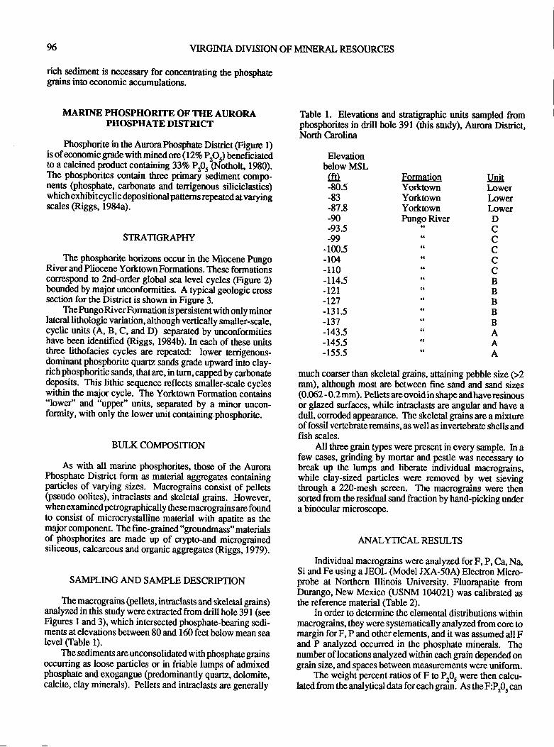
96 VIRGIMA DTVISION OF MINERAL RESOI.JRCES
rich sediment is necessary for concentrating the phosphategrains into economic accumulations.
MARINE PHOSPHORITE OF THE AUR.ORAPHOSPHATE DISTRICT
Phosphorite in the AurmaPhosphate District @gure l)is of economic grade with minedore(lT%o Pp.) beneficiatedto a calcined product containing 337o Pp.-(N-otholt, 1980).The phosphorites contain three primalry -sediment
compo-nents (phosphate, carbonate and terrigernus siliciclastics)which exhibit cyclic depositional patrerns repeated at varyingscales @iggs, 1984a).
STRATIGRAPHY
The phosphorite horizons occur in the Miocene FungoRiver and Pliocene Yorktown Formations. These formationscoreqpond o 2nd-order global sea level cycles (Frgure 2)boundedby major unconformities. A typical geologic crosssection for the District is shown in Figure 3.
ThePungoRiverFormation is persistentwith only minorlateral lithologic variation, although vertically smaller-scale,cyclic units (A, B, C, and D) separated by unconformitieshave been identified (Riggs, 1984b). In each of ttrese unitsthree lithofacies cycles are repea.ted: lower terrigenous-dominant phosphorite quartz sands grade upward into clay-richphosphoritic sands, thatare, in Orn, cappedby carbonatedeposits. This lithic sequence reflects smaller-scale cycleswithin the major cycle. The Yorktown Formation contains"lower" and "uppe.r" units, separated by a minor uncon-formity, with only the lower unit containing phosphorite.
BULK COMPOSITION
As with all marine phosphorites, those of the AuroraPhosphate District form as material aggegates containingparticles of varying sizes. Macrograins consist of pellets(pseudo oolites), inEaclasts and skeletal grains. However,when examined penographically these maoograins are forndto consist of microcrystalline material with apatite as themajor component. The fine-grained "groundmass" materialsof phosphorit€s are made up of crypto-and micrograinedsiliceous, calcareous and organic aggegates @iggs- 1979).
SAMPLING AND SAMPLE DESCRIPTION
The macrograins (pellets, intaclasts and skeletal grains)analyzed in this study were extracted from drill hole 391 (seeFigures 1 and 3), which intersected phosphate-bearing sedi-ments at elevations between 80 and 160 feet below mean sealevel (Table 1).
The sedimen6 are unconsolidated with phosphate grainsoccurring as loose particles or in friable lumps of admixedphosphate and exogangue (predominantly quartz, dolomite,calcite, clay minerals). Pellets and innaclasts are generally
Table 1. Elevations and sratigraphic units sampled fromphosphorites in drill hole 391 (this surdy), Aurora Disrict,North Carolina
Elevationbelow MSL
GTI-80.5-83-87.8-90-93.5-99
-100.5-104-110-il4.5-t2l-L27-131.5-r37-r43.5-r45.5-155.5
Formation UnitYorktown ItwerYorktown LowerYorktown LowerPungoRiver D"c"c"c"c"c
"B"BttB*B"B"A"A"A
much coarser than skeleal grains, attaining pebble size (>2mm), although most are between fine sand and sand sizes(0.062 -0.2mm). Pellets areovoid in shape andhaveresinousor glazed surfaces, while intraclasts are angular and have adull, corroded appearance. The skeletal grains are a mixtureof fossil vertebrate remains, as well as invertebrate shells andfish scales.
All three grain types were present in every sample. In afew cases, grinding by mortar and pestle was necessary tobreak up tlrc lumps and liberate individual macrograins,while clay-sized particles were removed by wet sievingthrough a 220-mesh screen. The macrograins were tlensorted from the residual sand fraction by hand-picking undera binocular microscope.
ANALYTICAL RESULTS
Individual macrograins were analyzed forF, P, C4 Na,Si and Fe using a JEOL (Model JXA-50A) Electron Micro-probe at Northem Illinois Univenity. Fluorapatite fromDurango, New Mexico (USNM 104021) was calibrated asthe reference material (Table 2).
In order to determine the elemental disnibutions withinmacrograins, they were systematically analyzed from core tomargin for F, P and other elements, and it was assumed all Fand P analyzed occuned in the phosphate minerals. Thenumber of locations analyzed within each grain depended ongrain size, and spaces between measurements were uniform.
The weight percent ratios of F o P,0. were then calcu-lated from the analytical data for each grain. As the F:P'O, can
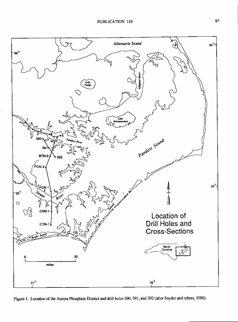
PUBLICATION I19 97
Albenarle Sourd 36
a.t(st
!
Paali"o nire,
d-\ t'"t$il
,d*oJzt//
A-N-
I
35q
Location otDrill Holes andCross-Sections
77o 76o
DB cNN'l
Figrue l. Location of the Auora Phosphate Disrict and drill holes 390, 391, and 392 (after Snyder and others, 1986).
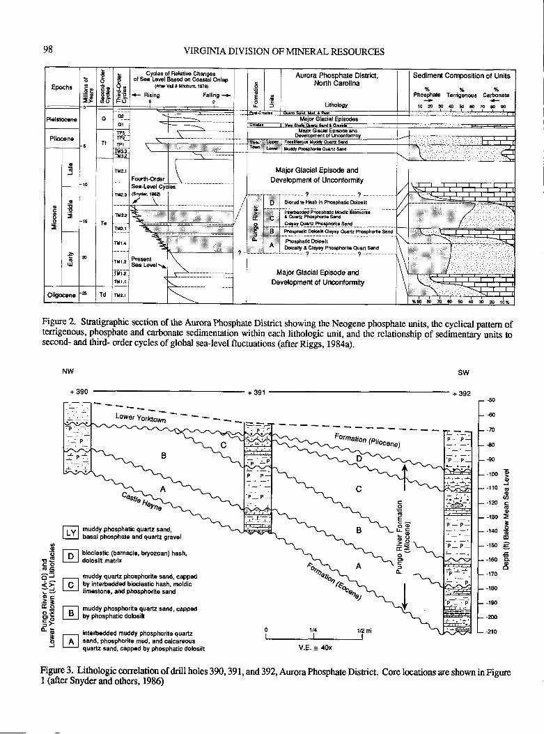
98
interbedded muddy phosphorite quartzsand, phosphorhe mud, and calcareousquartz sand, capped by phosphatic dolosilt
VIRGIMA DIVISION OF MINERAL RESOURCES
+ 391
V.E. = 40x
Fig$e 2. Sqtigraphic section of the Aurora Phosphate District showing rhe Neogene phosphate units, rhe cyclical pauern ofterrigenous, phosphate and carbonat€ sedimentation within each lithologic unit, inO tlie reiationship of sedimentary units tosecond- and thfud- order cycles of global sea-level fluctuations (after Riggs, 1994a).
NW
+ 390
sw
+ 392
T.-._: P
'-p--: ;N4€4\z\2r
co(,Eo(l)
P_ P.
.P- P.:-P--
!'r.-p :l\.2\-/P- P_
!-r-!'P- P.
-26*
ir.;P- P
t LYj ;;;ifi;"p["t"'",i-qu"rr. g'"""r
l-;l bioclastic (barnacle, bryozoan) hash,ljl dolosih matrix
-, muddy quartz phosphorite sand, cappsd
I C I UV interbedded bioclasric hash, moldic! limeslone, and phosphorhe sand
=l muddy phosphorile quartz sand, capped
D I by phosphatic dolosih
69>.Y \ii= \o\-CDcfo-
r\.\
P-P:.-
'P-.,:- '- P,
----:.P.-. P
- -50
-€0
- -70
-€0
- -90
- -100
- -120
- -130
- -140
- -150
- -160
- -170
- -t8o
- -190
- -200
- -2r0
oo
J(6ooc(!(D
3-9(Do
;o.(l,o
@.q,(,
rScoa!5^'-tt-J9c..'tfoOJ96=>o.b
3oJ
fig{" 3a Lithologic conelation of drill holes 390, 391,and,392. Aurora Phosphate Disrict. Core locarions are shown in FigureI (after Snyder and ottrers, 1986)
EpochsE
=e
=t
*
-g60
E
t-9E>F()
Cyclos ol R€laliw Chanoegot S€a'Lswl Bas€d on Coastil Onlap
(Atr vrlt I Mh.fiu4 1979)
+ Ri8ing Falling +o6tror
Aurora Phosphate Districi,North Carolina
Urhology
Sediment Composition of Units
%%%Pho8phato Tenigenoue Carbonata+1020s4050s70&s
Plelsto6n.
n
Major Glacial Episod€s
PlioceneT'
_'tt3__I!2_
HAls Gla*l Eprsode aodDevdopmst ol Unqlmiv
Yfilq
ooE
=
o6
J
IU9J
7
L#
t
\. E
Fourth-OrderSea-Lev-iT!(Snydr. l$a
MaFr Glacial Episode and
Development of Uncontormity
Te
T*2.
\Ilr2.3
1U22
TM2.I
-lPEp=
f-.-,::r------- ! --------------- f -'I O,"::l Sion ib lbsh in Pholphatjc Dol6ilt
\H:<-r
t j l Inr{b€dd€dPhooDhdlcl+ohtcBtomtcdleli I C I tQu.rEPholphdfiesod:::O i | ,:::::::l Cbyet Oi!ro Phorphqit. Sod
PrsrentS€a Lewl\
I .,f . l- -l -teryr-rg:l9i:r gqtgryr 91A I . I PholphsricDobsitr
| ^ | Ootoaity a Clayay Phosphtrib Ouan Ssd
\GIJJ
TIII J
Ilt r.3
-rut; -ru:I'.,.1i
:.:.:.:.:,t\ Major Glacial Episode andDevelopment of Urrconlormilyn 1.1 \l--.iFOligocene
.6Td TH2. l
6b 5b d, si: * ti*
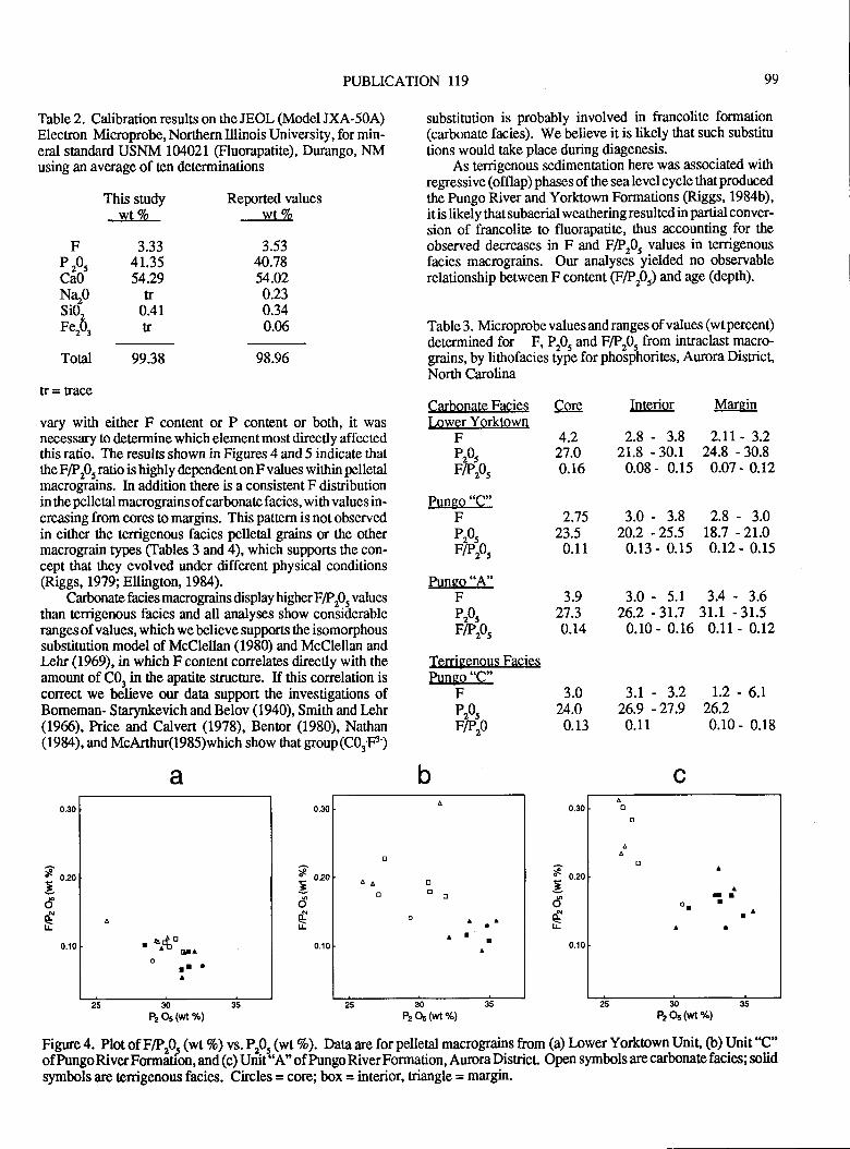
PUBLICATION 119 99
Table 2. Calibration results on the JEOL (Model JXA-50A)Electron Microprobe, Northern Illinois University, for min-eral standard USNM lMWl. @uorapatite), Durango, NMusing an average of ten determinations
substitution is probably involved in francolite formation(carbonate facies). We believe it is likely that such substitu
tions would take place during diagenesis.As terrigenous sedimentation here was associated with
regressive (offlap) phases ofthe sealevel cycle thatproducedthe Pungo River and Yorktown Formations (Riggs, 1984b),it is likely that subaerial weathering resulted in partial conver-sion of francolite to fluorapatite, thus accounting for theobserved decreases in F and F7P"0. values in terrigenousfacies macrogains. Our analysel yietOed no observablerelationship between F content (tprOrl and age (depth).
Table 3. Microprobe values and ranges of values (wt percent)
determined for F, P.0. and F/P"O. from intraclast macro-grains, by littrofacies tyfe for phoiphorites, Aurora District,North Carolina
Carbonate Facies Core Interior MarqinLower Yorktown
4.2 2.8 - 3.8 2.rr - 3.227.0 21.8 - 30.1 24.8 - 30.80.16 0.08 - 0.15 0.47 - 0.12
F 3.33P r0, 41.35CaO 54.29NqO trsi02 0.4rFerq a
This studywtTo
Reported valueswIlo
3.5340.7854.020.230.340.06
Toal 99.38
[r = trace
98.96
vary with either F content or P content or both, it wasnecessary to determine which element most directly affectedthis ratio. The results shown in Figures 4 and 5 indicate thatttre F/Pr0, ratio is highly dependenton F values within pelletalmacrograins. In addition there is a consistent F disributionin the pelletal macrograins of carbonate facies, with values in-creasing from cores to margins. This pattern is not observedin either the terrigenous facies pelletal grains or the othermacrograin types (Iables 3 and 4), which supports the con-cept that they evolved under different physical conditions(Riggs, 1979; Ellington, 1984).
Carbonate facies macrograins display higher F/Pr0, values
than tenigenous facies and all analyses show considerableranges of values, which we believe supports the isomorphoussubstitution model of McClellan (1980) and McClellan andl*hr (1969), in which F content correlates directly with theamount of C0, in the apatite structure. If this correlation iscorrect, we believe our data support the investigations ofBomeman- Starynkevich and Belov (1940), Smith and lrhr(1966), Price and Calvert (1978), Bentor (1980), Nathan(1984), and McArttrur(l985)which show that group (C03'F)
a
. 64o'- ota
orl 'A
30
P2 05 (wt %)
b
o
aalr
I
3.0 - 3.8 2.8 - 3.020.2 -25.5 18.7 -21.0
0.13 - 0.15 0.12 - 0.15
3.0 - 5.1 3.4 - 3.626.2 -3r.7 31.1 -31.50.r0 - 0.16 0.11 - 0.12
3.r - 3.2 r.2 - 6.r26.9 -27.9 26.20.11 0.10 - 0.18
c
-t^l
a
30
P2 05 (wl 7")
FP&FlPz0s
Pungo "C"FP"0.FIpr0,
Pungo "A"FP&F/p205
Terrigenous Facig$Pungo "C"
FP&FErA
2.7523.5
0.11
3.927.30.14
3.024.0
0.13
8 o.*
';odtr
3'5oaN
tr
s o.m
';odtr
0.10
30
P2 Os (wt 7")
Fignre 4. Plot of F/P,Q (wt%o\ vs. P,0. (wtVo). Data are for pelletal macrognins from (a) lower Yorkown Unit" O) Unit'C"ofPungoRiverFormfuion,and(c)Uriitr'A"ofPungoRiverFormation,AuroraDisrict Opensymbolsarecarbonatefacies;solidsymbols are tenigenous facies. Circles = corei box = interior, triangle = margin.
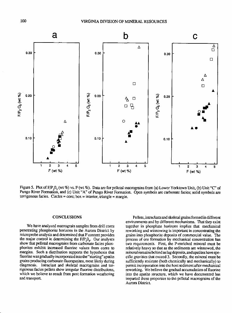
100 VIRGIMA DIVISION OF MINERAL RESOURCES
0.10
23F (wt %)
0.10
23F (wt %)
CONCLUSIONS
We have amlyzed,macrograin samples from drill corespenefating phosphorite horizons in the Aurora Disfict bymicroprobe analysis and determined that F content providesthe major control in determining the FlPp.. Our analysesshow that pelletal macrograins from carb5nate facies phos-phorites exhibit increased fluorine values from cores tomargins. Such a distribution supports the hypothesis ttratfluorine was gradually incorporated into the "starting" apatitegrains producing carbonate fluorapatites, most likely duringdiagenesis. Intraclast and skeletal macrograins and ter-rigenous facies pellets show inegular fluorine distributions,which we believe to result from post formation weatheringand transport.
cba
0.300.300.30
S o.2o
5d"f,[L-
S o.2o
;d"
N(Ll!-
S o.2o
3
ddli-
0.10
Figure 5. Plot of F/Pr0, (wt 7o) vs. F (wt 7o). Data are for pelletal macrograins from (a) Lower Yorktown Unit, (b) Unit "C" ofPungo River Formation, and (c) Unit "A' of Pungo River Formation. Open symbols are carbonate facies; solid symbols areterrigenous facies. Circles = coroi box = interior, triangle = margin.
23F (wt %)
Pellets, intraclasts and skeletal grains formed in differentenvironments and by different mechanisms. That they existtogether in phosphate horizons implies that mechanicalreworking and winnowing is important in concentrating thegrains into phosphorite deposits of commercial value. Theprocess of ore formation by mechanical concentration hastwo requirements. First, the P-enriched mineral must berelatively heavy so that as the sediments are winnowed, themineral remains behind as lag deposits, and apatites have spe-cific gravities that exceed 3. Secondly, the mineral must besufficiently resistate (both chemically and mechanically) topermit incorporation into the host sediment aft€r mechanicalreworking. We believe the gradual accumulation of fluorineinto the apatite structure, which we have documented hasimparted these properties to the pelletal macrograins of theAurora District
A
oaaO
AII
D
tr-tl"'ll
AD
tr
A
AA
D
Aa9rI
AOA
-AFfI
rtA
FF&
FP&FlPz0s
Terrigenous Facies
Pungo "C"F 3.0P"0. 30.0FlPro, o.1o
2.5 - 2.7 2.5 - 3.83r.2 -33.2 30.5 -32.90.08 0.07 - 0.12
REFERENCES CITED
Ames, L.L., Jr., 1959, The genesis of carbonate apatites:Econ. Geol., v. 54, p. 829-84l.
Baturin, G.N., 1982, Phosphorites on the sea floor<rigin,composition and disribution: Elsevier, New Yolk, 343 p.
Baturin, G.N., and Shishkina, O.V., 1973, Behavior of fluo.rine during phosphorite formation in the ocean: Oceanology,v.13,p.523-527.
Bentor, Y.K., 1980, Phosphorites-the unsolved problems:in Bentor, Y.K., (ed.): Marine phosphorites-geochemsitry,occurrence, genesis: SEPM Special Publication 29, p. 3-18.
Bomeman-Starynkevich, I.D., and Belov, N.V., 1940, Iso-morphic substitutions in carbonate-apatite: C.R. Ac. Sci.,USSR, v. ?6,p.804-806.
Burnett, W.C .,1977 ,Geochemistry and origin of phosphoritedeposits from off Peru and Chile: Geol. Soc. Amer. Bull., v.88, p. 813-823.
Cook, PJ., 1976, Sedimentary phosphate deposits, in Wolf,K,H., (ed.), Handbookof strata-hundand stratiform depos-its: Elsevier, New York, v. 7, p. 505-535.
Ellington, M.D., 1984, Major and race element compositionof phosphorites of the North Carolina continental margin:East Carolina University, unpublished M.S. thesis,96 p.
PUBLICATION 119
Froelich, P.N., Kim, K.H., Jahnke, R., Burnett" W.C., Sontar,
A., and Deakin, M., 1983, Pore water fluoride in Peru conti-nental margin sediments-uptake from sea watec Geochim.Cosmochim. Acta, v. 47, p. 1605-1612.
Gaudette, H.8., and Lyons, W.B., 1980, Phosphate geochem-
istry in nearshore carbonate sedimens-a suggestion ofapatite formation: in Bentor, Y.K., (ed.): ldarine phosphor'
ites-geochemistry, occturence, genesis: SEPM Special
Publication 29, p. 215 -225.
Kolodny, Y., 1980, The origin of phosphorite deposits in the
light of occurences of recent sea-floor phosphorites, inBLntor, Y.K., (ed.): Marine phosphorites--geochemistry,occrurence, diagenesis: SEPM Special Publication 29, p.
249.
Kramer, J.R., 1964, Seawater-saturation with apatites and
carbonates: Science, v. L46, p. 637 -638.
McArthur, J.M, 1985, Francolite geochemistry---composi-tional controls during formation, diagenesis, metamorphismand weathering: Geochim. Cosmochim. Acta,v. 49,p.23'25.
McClellan, G.H., 1980, Mineralogy of carbonate fluora-patites: J. Geol. Soc. london,v.137,p. 675681.
McClellan, G.H. and l€hr, J.R., 1969, Crystal chemicalinvestigation of natural apatites: Amer. Mineral., v. 54, p'r374-r39r.
McClellan, G.H., Van Kauwenburgh, and Ishording, W.C.,1986, Mineralogical overview of phosphorite deposits: inRiggs, S.R. and Snyder, S.W., (eds.): Pattems of cyclic sedi-mentation of the Upper Cenozoic Section, North Carolina-
Coastal Plain: SEPM Third Annual Midyear Meeting,FieldTrip Guidebook, No. 9, p.336-372.
Nathan, Y., 1984, The mineralogy and geochemisry ofphosphorites: iz Nriagu, J.O. and Moore, P.8., (eds): Phos-phate Minerals, New York Springer-Verlag, p.TI6-291.
Notholt, A.J.G., 1980, Economic phosphatic sediments-mode of occurrence and sfiatigraphical distribution: J. Geol.Soc. London,v. I3'1, p. 793- 805.
Price, N.B, and Calvert, S.E., 1978, The geochemisry ofphosphorites from the Namibian shelf: Chem. Geol, v. 23, p.
151-170.
Riggs, S.R, 1979, Petrology of the Tertiary phosphorite
system of Florida: Econ. Geol, v.74,p.195-220.
Riggs, S.R., I 9 80, Inraclast and pellet phosphorite sedimen-
tation in theMioceneofFlorida: J. Geol. Soc.London, v. 137,p.74r-748.
Riggs, S.R., 1984a, Patterns of Miocene phosphate sedimen-
cation on the southeastern United States continental margin:Proceedings of the 2Tth lnternational Geological Congress,
v. 15, p. 201-222.
101
Table 4 . Microprobe values and ranges of values (wt percent)
determined foF, Pp, and F7Pr0, from skeletal macrograinsby lithofacies type icir phosph6rins, Aurora District, NorthCarolina
Carbonate FaciesCore Interior Margin
Lnwer Yorktown2.8 3.1 - 3.5 3.1 - 3.8
28.2 30.8 - 34.7 29.7 -35.90.10 0.10 - 0.1I 0.09 - 0.12
FP&
Pungo "C"F 3.2P"0. 27.2F-lPrq, 0.12
Pungo "A:3.5
19.20.18
2.3 - 2.623.8 -29.50.09 - 0.10
3.8 - 4.225.2 -25.40.16 - 0.17
1.8 - 3.022.2 -30.0
0.10
3.2 - 4.7r7.6 -2r.30.19 - 0.25
r02 VIRGINIA DIVISION OF MINERAL RESOURCES
RiSBs, S.R., 1984b, Paleoceanographic model of Neogenephosphorite deposition, U.S. Atlantic conrinental margin:Science, v.223,p. 123- 131.
Roberson, C.8., 1966, Solubility implications of apatite insea water: U.S. Geol. Surv. Prof. Paper 55GD, p. D1Z8-D185.
Ryther, J.H., 1963, Geographical variation in productivity: inI{ill, N.M., (ed.): The Sea, New York: Interscience, v. 2, p.347-380.
Slansky, M., 1986, Geology of sedimentary phosphates:Elsevier, New Yok, 210 p.
Smith, J.P., and Lehr, J.R,., 1966, An X-ray investigation ofcarbonate-apatite: J. Agric. Fmd Chem., v. 14, p. 342-yg.
Snyder, S.W., Crowson, R.A., Riggs, S.R., and Mallette,P.M., 1986, Geology of the Aurora Phosphate District" inRiggs, S.R., and Snyder, S.W., (eds.): patterns of cyclic sedi-mentation of the Upper Cenozoic Section, North CarolinaCoastal Plain, SEPM Third Annual Midyear Meeting,FieldTrip Guidebook No. 9, p. 345-357.
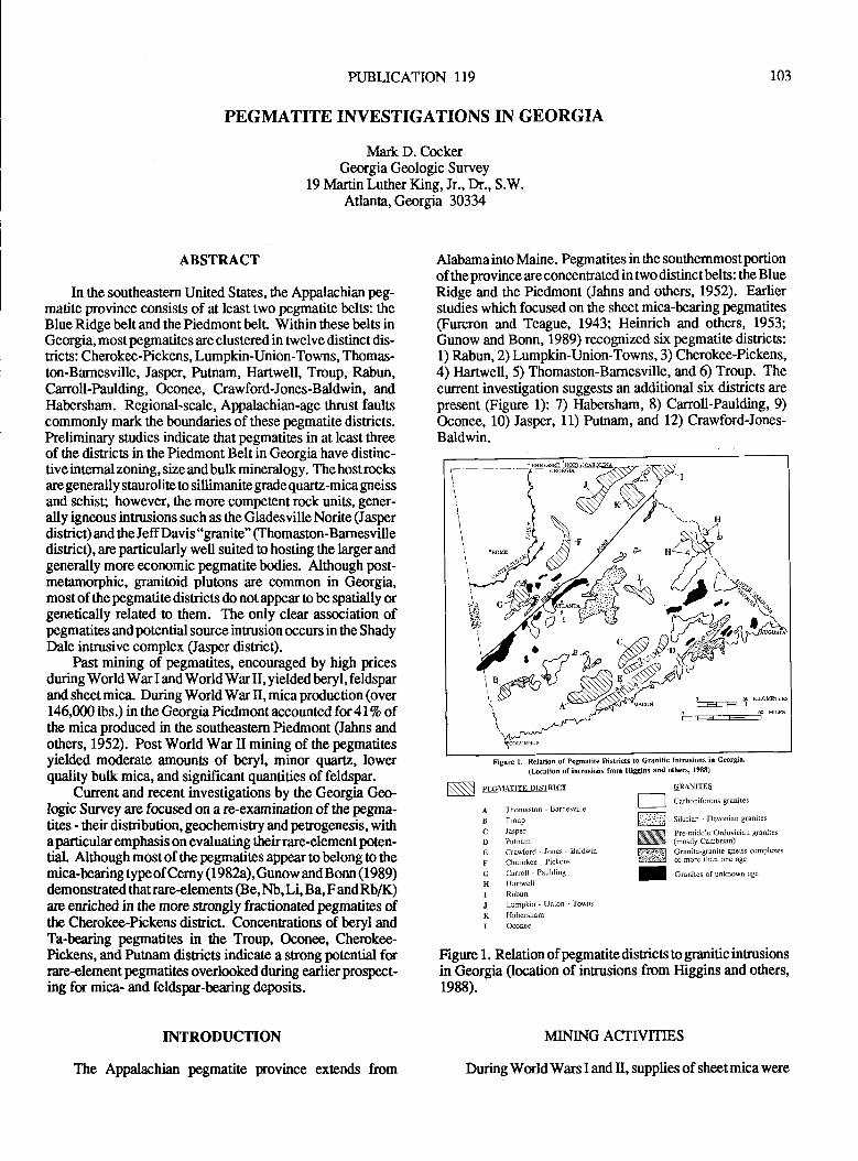
PUBLICATION T19
PEGMATITE INVESTIGATIONS IN GEORGIA
Mark D. CockerGeorgia Geologic Survey
19 Martin Luther King, Jr., Dr., S.W.Atlanta, Georgia 30334
103
ABSTRACT
In the southeastern United States, the Appalachian peg-matite province consisls of at least two pegmatite belts: theBlue Ridge belt and the Piedmont belr Within these belts inGeorgia, mostpegmatites are clustered in twelve distinct dis-rics: Cherokee-Pickens, Lumpkin-Union-Towns, Thomas-ton-Barnesville, Jasper, Putnam, Harfwell, Troup, Rabun,Canoll-Paulding, Oconee, Crawford-Jones-Baldwin, andHabersham. Regional-scale, Appalachian-age thrust faultscommonly mark the boundaries of these pegmatite disnicts.Preliminary studies indicate that pegmatites in at least threeof the districts in the Piedmont Belt in Georgia have distinc-tive internal zoning, size andbulk mineralogy. The hostrocksare generally staurolite to sillimanite grade quarz-mica gneissand schist; however, the more competentrock units, gener-ally igneous inftusions such as the Gladesville Norite (Jasperdisrict) and the Jeff Davis "granite" (Thomaston-Barnesvilledisrict), are particularly well suited o hosting the larger andgenerally more @onomic pegmatitebodies. Although post-metamorphic, granitoid plutons are common in Georgia,most of thepegmatite districts do notappear to be spatially orgenetically related to them. The only clear association ofpegmatites and potential source intrusion occurs in the ShadyDale intrusive complex (Jasper disnict).
Past mining of pegmatites, encouraged by high pricesduring WorldWar I and World War II, yielded beryl, feldsparand sheet mica. During World War II, mica production (over146,0001bs.) in the Georgia Piedmont accountedfor4l%o ofthe mica produced in the southeastem Piedmont (Jahns andothers, 1952). Post World War II mining of the pegmatitesyielded moderate amounts of beryl, minor quartz, lowerquality bulk mica, and significant quantities of feldspar.
Cunent and recent investigations by the Georgia Geo-logic Survey are focused on a re-examination of the pegma-tites - their distribution, geochemistry and petrogenesis, withaparticular emphasis on evaluating theirrare-element poten-tial. Although most of the pegmatites appear to belong to themica-bearing typeof Cerny (1982a),Gunew andBonn (1989)demonstrated thatrare-elements (Be, Nb, Li, Ba,F andRb/K)are emiched in the more strongly fractionated pegmatites ofthe Cherokee-Pickens disnict. Concentrations of beryl andTa-bearing pegmatites in the Troup, Oconee, Cherokee-Pickens, and Putnam disricts indicate a strong potential forrare-element pegmatites overlooked during earlier prospect-ing fu mica- and feldspar-bearing deposis.
INTRODUCTION
The Appalachian pegmatite province extends from
Alabama ino Maine. Pegmatites in the southemmostportionof theprovince areconcenEated in two distinctbelts: the BlueRidge and the Piedmont (Jahns and others, 1952). Earlierstudies which focused on the sheet mica-bearing pegmatites(Furcron and Teague, 1943; Heinrich and others, 1953;Gunow and Bonn, 1989) recognized six pegrnatite districts:1) Rabun, 2) Lumpkin-Union-Towns, 3) Cherokee-Pickens,4) Hartwell, 5) Thomaston-Barnesville, and 6) Troup. Thecurent investigation suggests an additional six disnics arepresent figure 1): ?) Habersham, 8) Carroll-Paulding, 9)Oconee, 10) Jasper, 11) Putnam, and 12) Crawford-Jones-Baldwin.
'\-^. H
N$na<\i{f )':.
9***s
O S KrcWEE
o----_-+ m
Figure l. Relation of Pcgmatite Districts to Gnnitic Intrusions in G@rgi8'
(Ircation of ihtrusions fmm Higgins and oth€rs' 19E8)
Nl ot.nn^tt"" ottt*t"t
A Thomaslon - Barneslille
B Troup
C Jasper
D Putnam
E Craw{ord - Jones _ Baldwin
F Cherokee - Pickens
G Carroll - Paulding
H Hartwell
I Rabutr
J LumPkin - Union - Towns
K llabersham
L Oconee
GRAh-ITES
l--l cu.bonif".ou, gruni,",
Fffl situ,ion - Devonian g.anites
N,t;:.liitgi""3:*w)ician eranites
lDTll) Cranitc-grnile gneiss complexes[1642 of nore Lhxn one age
! Groni,", ofunknown age
Figure 1. Relation of pegmatite disrics o granitic intrusionsin Georgia (location of intrusions from Higgins and others,1988).
MINING ACTIVITMS
DuringWorldWars Iand tr, supplies of sheetmicawere
104 VIRGIMA DIVISION OF MINERAL RESOURCES
restricted, causing an increase in demand. Higher, subsidizedprices encouraged prospecting and mining of mica-bearingpegmalites in Georgia. Beryl was also mined locally as astrategic mineral. Exlensive mining of potassic and sodicfeldspar-bearing pegmatites began during the 1950s. Al-though current production of feldspar, sheet and flake mica,andberyl from pegmatites is greatly reduced in Georgi4 thepotential is encouraging for further development.
Initial mica production in Georgia was cen&ered in thenorthem part of tlre Blue Ridge pegmatite belt. prior to 1908,most of the mica production in Geogia was from the Lump-kin-Union-Towns disrict. From 1909 to 1918, the Chero-kee-Pickens district was the leading producer. Dwindling re-serves in the Blue Ridge, the discovery of rich, mica-bearingpegmatites in thePiedmont,and theeaseof saprolite vs hard-rock mining all probably conributed to the shift of produc-tion to the Thomaston-Barnesville and llartwell disrics inthe Piedmont belf During the period lg|7-24,output fromtlp Thomaston-Barnesville disnict is estimated ai severalhundred thousand pounds of rimmed mica (Heinrich andothers, 1953). During World War II, the Thomaston-Bar-nesville disrict was ttre leading producer of sheet and punchmica in the southeastern Piedmont of *re United States with114,165 pounds c 32 percent of the toal production (Jahnsand others, 1952). Sixty-two percent of this production camefrom 4 mines: Adams, Battles, Early Vaughn and MtchellCreek (Heinrich and others, 1953). Although published,comprehensive data is incomplete following World War II,productionof sheet micaapparentlycontinuedin a few of thelarger mines at a decreased level into the early 1960s whenprice subsidies were discontinued. Yearly production ofsheet mica in Georgia ranged from 9,000 to l?,000 lbslyearduring this period. Scrap and sheet mica production contin-ues at the present time in a few mines in the Hartwell andCherokee-Pickens districts (Gunow and Bonn, 1989).
Feldspar production from pegmatites is historicallycentered in the Jasper district, although several of the large,zoned pegmatites in the Thomaston-Bamesville districtapparently produced potassic feldspar as a by-product ofmica production. The Jasper disrict pegmatites containmainly high-potassium (6-13%o) feldspar (Whitlarch, 1962),although a soda-rich feldspar was produced from a largepegmatite near Enon Church toward the southern end of thedisrict.
During the period 1952-1957,178,300 pounds of berylwere produced from 5 pegmatite mines. Most of the produc-tion ( I 72,400 lbs.) was from the Foley or Hogg mine in TroupCounty. The remainder was produced from the Bennett andCochran mines (4,000lbs.). (Reno, 1956) and the DensonMines (1,500lbs.) in the Cherokee-Pickens district, and fromthe High Shoals area (400lbs.) in the Oconee district (Furcron,1959). Renewed production is currently underway at theCochran mine (J. Connor, 1990, personal communication)with 200,00G240,000 lbs. of beryl produced during 1985(Gunow and Bonn, 1989).
The large quartz-cored pegnatites in putnam Countywere briefly mined by the Quanz International Corporation(Koch and ottrers, 1984 and 1987). The amountofproductionis unknown, but based on the size of tfre workings, amountedto less than 100 ons.
PREVIOUS STUDIES
Prior to World War I, there are no comprehensive s$diesof Georgia pegmatites. The first investigation (Galpin,1915), located and described numerous aplite dikes in addi-tion !o the feldspar and mica pegmatites. Because of thescarcityof prospectingor development up to thattime, manypegmatites were not recognized. Furcron and Teague (1943)described a significantly larger number of mica-bearingpegmatite.s that had been discovered and developed duringthe war and during the initial stages of World War II. Peg-matite investigations (Beck, 1948; Jahns and others, 1952;Grifliss andOlson, 1953; Heinrich andothers, 1953) ataineda high level of intensity with the exiensive prospecting foranddevelopment of mica-bearing pegmatites throughout the sou0r-eastern Piedmont These investigations provide imporantinformation on the mineralogy, internal zoning and sEuctureof thepegmatites in the soufteastern Piedmont. Because ofthe extensive weathering and the present scarcity of fresh ex-posures, this information on the pegmatites is impossible overify at this time.
Despite the continuation of mica mining into the early1960s and the development of feldspar-rich pegmatites, peg-matites in Georgia generally have been ignored in the geo-logic literature. Occasional mineral resource studies oncounties or regions contain locations and brief descriptions ofthe pegmatite mineralogy (Hurst and Crawford, 1964; Huntand Otwell, 1964). Pegmatites often are noted as mineralcollecting localities (Cook, 1978), but litrle new informationhas been generated.
Recently, Gunow andBonn (1989) studied the geochem-istry of pegmatite micas in the Cherokee-Pickens disfict aspad of the Accelerated Minerals hogram of the GeorgiaGeologic Survey. Current investigations involve the sam-pling of mica and feldspar from pegmatites throughout Geor-gia.
CLASSIFICATION OF GRAMTIC PEGMATITES
Granitic pegmatites are coarse-grained, dike-like inru-sions generally composed of various proportions of quartz,mica (generally muscovite), and feldspar (generally potassicor sodic). One or more accessory minerals atso may bepresenL Granitic pegmatites are classified on the basis ofgeological-petrogenetic criteria developed by Ginsburg andothers ( 1 979) and recently introduced into North America byCerny (1982a). The four basic types of pegmatites are: l)miarolitic pegmatites, 2) rare-element pegmatites, 3) mica-bearing pegmatites, and4) maximal depth pegmatites (Cerny,1982a). Brief descriptions of each type given below are basedon Cemy (1982a).
Miarolitic pegmatitesoccur as pods in the upperpar$ ofepizonal granite intrusions that are emplaced into low-grademetamorphic country rocks. These pegmatites are character-iz.ed by crystal-lined cavities containing quartz, fluorite,beryl, topaz, etc.
Rare-element pegmatites generally occur in cordierite -amphibolite facies metamorphic rocks peripheral to differen-tiated allochtonous granites. These pegmatites are formed at
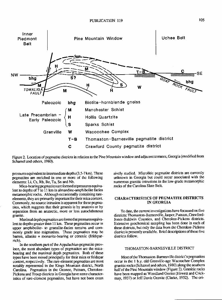
PUBLICATION 119
Pine Mountain Window
105
lnnerPiedmont
BeltUchee Belt
NWbhg S- bhg4F ,94F---)
TOWALIGAFAULT
FAd
Paleozoic
Late Precambrian -Early Paleozoic
bhg
Grenville wT.Bc
pressures equivalentto intermediate depths (3.5-7 km). Thesepegmatites are enriched in one or more of ttre followingelements: Li, Cs, Rb, Be, Ta, Sn andNb.
Mica-bearing pegmatites are formed at pressures equiva-lent to depths of 7 to 11 km in almandine-amphibolite faciesmetamorphic rocks. Although occasionally containing rare-elements, they are primarily important for their mica content.Commonly, no source inEusion is apparentfor these pegma-
tites, which suggests that their genesis is by anatexis or byseparation from an anatectic, more or less autochthonousgranite.
Maximal depth pegmatites are formed atpressures equiva-lent to depths greater than 11 km. These pegmatites occur inupper amphibolite- to granulite-facies tenains and com-monly grade into migmatites. These pegmatites may bebarren, allanite + monazite-bearing or ceramic (feldspar-rich).
In the southern part of the Appalachian pegmatite prov-ince, the most abundant types of pegmatites are the mica-bearing and the maximal depth pegmatites. Both of these
types have been mined principally for their mica or feldsparcontent, respectively. The rare-element pegmatites are mostnotably represented in the Kings Mountain district, NorthCarolina. Pegmatites in the Oconee, Putnam, Cherokee-Pickens and Troup districts in Georgiahave some chinacter-istics of rare-element pegmatites, but have not been exten
Biotite-horn blende gneiss
Manchester Schist
Hollis Quartzite
Sparks Schist
Wacoochee ComPlex
Thomaston-Barnesville pegmatite district
Crawford County pegmatite district
f'1"Is
Figure 2. Location of pegmatite districts in relation to the Pine Mountain window and adjacent terranes, Georgia (modified from
Schamel and others, 1980).
sively studied. Miarolitic pegmatite disricts are cunentlyunlnown in Georgia but could occur associated with the
numerous granitic intrusions in the low-grade metamorphicrocks of the Carolina Slate Belt.
CHARACTERISTICS OF PEGMATITE DISTRICTSIN GEORGIA
To date, the current investigations have focussed on fivedisricts: Thomaston-Barnesville, Jasper, Putnam, Crawford-Jones-Baldwin Counties, and Cherokee-Pickens districts.Extensive geochemical sampling has been done in each ofthese districts, but only the data from the Cherokee-Pickens
disrict is presently available. Brief descriptions of these fivedisricts follow.
TI{OMASTON.BARNE S VILLE DIS TRICT
Most of the Thomaston-Barnesville district' s pegmatites
occur in the 1 b.y. old Grenville-age Wacoochee Complexgranitic rocks (Schamel and others, 1980) along t}e southern
haf of tne pine Mountain window @gure 2). Granitic rockshave been mapped as Woodland Gneiss (Hewett and Crick-may, 1937) or Jeff Davis Granite (Clarke, 1952). The ori-
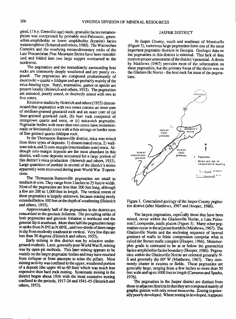
106 VIRGINIA DIVISION OF MINERAL RESOURCES
ginal, (l b.y. Grenville-age) static, granulite facies mecamor-phism was overprinted by probably mid-paleozoic, green-schist-amphibolite or lower amphibolite (kyanite) laciesmetamorphism (Schamel and others, 1980). The WacoocheeComplex and the overlying metasedimentary rocks of thel,ate Precambrian Pine Mountain Series have been remobil-ized and folded into two large nappes overturned to thenorthwest.
The pegmatites and the immediately surrounding hostrocks are commonly deeply weathered and are poorly ex-posed. The pegmatites are composed predominantiy ofmuscovite + quartz + feldsparandareprobably mainly of themica-bearing type. Beryl, tourmaline, g,lmet or apatite arepresent locally (Heinrich and others, 1953). The pegmatitesare unzoned, poorly zoned, or distinctly zoned with two tofive zones.
Extensivesrudiesby Heinrich and others (1953) demon-strated that pegmatites with two zones contain an inner coreof medium-grained granitoid rock and an outer core of (a)finer-grained granitoid rock, (b) burr rock composed ofintergrorvn quartz and mica, or (c) mica-rich pegmatite.Pegmatite bodies with more than two zones have monomin-eralic or bimineralic cores with a thin selvage or border zoneof fine-grained quartz-feldspar rock.
In the Thomaston-Barnesville disrict, mica was minedfrom three types of deposits: 1) disseminated mica,2) wall-zone mica, and 3) core-margin (intermediate zone) mica. Al-though core-margin deposits are the most abundant in thisdisEigt, wall-zone deposits accounted for a large portion ofthis district's mica prodrrction (Heinrich and others, 1953).Iarge quantities of perthite in several of the disrict's minesapparently were recovered during post-World War II opera-tions.
The Thomaston-Barnesville pegmatites are small tomedium in size. Theyrangefrom2irrches to25 feetinwidth.Most of the pegmatites are less than 200 feet long, althougha few are 200 to 1,000 feet in length. The vertical extentbfthese pegmatites is largely unknown, because mining rarelyextended below 100 feet or the depth of weathering (Heinrichand others, 1953).
Approximarely half of the pegmatires in the disrict areconcsdant !o the gneissic foliation. Theprevailing sEike ofboth pegmatites and gneissic foliation is northeast and thegeneral dip is sourheast. Moe than half the pegmatites nmgein strike from N.CIE to N.6OE., and nvo-ttrirdsof them range
in dip fror-nmodestly southeast to vertical. Very few dips areless than 30 degreas (Heinrich and others, 1953).
Early mining in this district was by selective under-ground methods. Later, generally post-Worldwar II, miningwas by open-pit methods. This later mining appears !o bemainly on the larger pegmatite bodies and may have resultedfrom collapse or from att€mpts to mine the pillars. Mostmining activity was confined to the upper, weathered portionof a deposit (the upper 40 to CI feet) which was much lessexpensive than hard rock mining. Systematic mining in thedisfict began about 1916 with the most extensive miningconfined to the periods, l9l7-M ndl94l45 (Heinrich andothers, 1953).
JASPER DISTRICT
In Jasper County, south and southeast of Monticello(Frgure 3), numerous large pegmatites form one of the mostimporant pegmatite disricts in Georgia. Geologic data onthe pegmatites in this district is minimal. This lack of datarestricts proper assessment of ttre district's potentiat, A thesisby ldatthews (1967) provides most of the informarion onthese pegmatites, but the primary focus of the thesis was onthe Gladesville Norite - the host rock for most of tlrc pegma-tites.
Peg matite
Strike and dip ofcompositional layering
O I 2 KLOME]EFS
0 I i M]LES
Figure 3. Generalized geology of the Jasper County pelina-tite district (after lvlatthews,1967 and Hooper, 1986).
The largest pegmatil.es, espeiiatty those that have beenmined, occur within the Gladesville Norite, aLate Paleo-zoic?, composite, mafic pluton (Figure 3). lvlany otherpeg-matites occur in the adjacent hornfels (ldatthews, 1967). TheGladesville Norite and the enclosing sequence of layeredgneisses of mafic o felsic composition comprise what iscalled the Bemer mafic complex (Hooper, 198Q. Mefamor-phic grade is estimated !o be at or below the greenschistfacies-amphibolite facies boundary (Hooper, 1986). Pegma-tiles within the Gladesville Norite are oriented generally N-S and generally dip 6tr W (Matthews, 1967). They com-monly cluster in swarms or fields. These pegmatites aregenerally large, ranging from a few inches !o more than 50feet wide and up to 1000 feet in length (Cameron and Sparks,1976\.
The pegmatites in the Jasper disrict are distinct fromthose in adjacent districts in that they are composed mainly ofgraphic granite with only minor muscovite. Zoning is gener-ally poorly developed. Where zoning is developed, it appears
N
I
PUBLICATION 119 t07
to consist ofa fine-grained granitoid border zone that gradu-
ally becoming coarser over a distance of 1 foot. Where thegrain sizebecomes greaterthan 1 inch, azoneof pinkgraphicgranite of microcline and quartz occurs. Small masses (<2feet) of quartz scattered on the mine dumps suggest a smallcore of massive qu:rtz may be developed in some of thesepegmatites. A pegmatite near Enon Church is conspicuouslyzoned with a sugary-texhred, quartz-feldspar border zone, ablocky perthite intermediate zone and a quartz core (Mat-thews, 1967). Unusual vermiculite veins (altered from bi-otite) commonly cut across the wall zones of these pegma-
tites.Prior to 1947, the pegmatites in the Jasper district were
mined for road gravel. Recognition of their potential forceramic feldspar led to the development of this district.Pegmatites within the district are no longer mined, becausethe open pit mining methods of dragline and bulldozerreached maximum safety and economic deptlts. Apparentlynone of ttre pegmatites have been bottomed by mining(Matthews, 1967).
Arareassociation in Georgiaof pegmatites within a hostsodic ganitic inEusion is currently being mined near ShadyDale, Jasper Co. The pegmatites are K-feldspar rich withminor quartz and muscovite. In addition to numerous epi-sodes of pegmatite intrusion and quartz veining, quartz andfeldspar textures within one of the pegmatites are strikinglysimilar to the crenulate textures present in the porphyry-hosted molybdenum inrusive systems at Henderson and MLEmmons in Colorado and at Cave Peak in Texas (White andothers, 1981). Thesepegmatites occur in a weakly foliatedtonon-foliated, muscovite + feldspar + quartz + garnet granite.Further study of this association at Shady Dale may provideevidence for a genetic link benveen the pegmatites and asoruce inEusion at Shady Dale and elsewhere in the Jasperdisnict.
PUTNAMDISTRICT
The pegmatites of the Pumam district occur in rockssimilar to the Berner mafic complex in the Jasper disrict.These pegmatites are characterized by their large quartz cores(>20 feet wide). The quartz cores, which are resistant toweathering and erosion, are exposed as conspicuous out-cnps. The large, prehistoric "Rock Eagle" mound north ofEa8onton is constructed of quartz blocks from one of thesepegmatites. A narrow rim of feldspar and mica is occasion-ally exposed by mining or prospecting activity. Tantalum-bearing minerals are reported from at least one of thesepegmatites (Cook, 1978). Predominantly feldspar-bearingpegmatites occur in the district, a few of which have beenselectively mined. Scauered quartz-molybdenite veins arealso reported nearby (Cmk, 1978). Minimal exposures inthis disrict limit determination of the geologic relationshipsbetween the different pegmatites.
C}IEROKEE-PICKENS DISTRICT
In this disricf the pegmatites occur in two fields (Holly
Springs and Ball Ground) located in different thrust sheets
which are sepamted by a barren thrust sheet. The host rocksare late Precambrian to early Paleozoic metasedimentary andmetaigneous rocks metamorphosed to the kyanite grade
(middle amphibolite- facies). The pegmatites are inegular,tabular or lenticular bodies which have widttrs ranging fromless ttran 3 feet to 100 feet and lengttrs ranglng from 15 feetto nearly 2000 feet (Gunow and Bonn, 1989).
While pegmatites in the two fieldsboth appearto belongto the muscovite class of Cerny (1982a), they differ in min-eralogy and geochemistry. In addition to muscovite, micro-cline, perthite, albite or oligoclase, and quartz, pegmatites inthe Ball Ground field contain tourmaline +/- beryl. Gunowand Bonn further divide the Ball Ground pegmatites based on
whether they are beryl-poor, beryl-bearing, or beryl-rich (the
Cochran pegmatite). Several pegmatites are zoned with aquartz core, an intermediate feldspar-quartz-muscovite-gar-net-tourmaline zone and a fine-grained border zone of feld-spar-quartz-muscovite. Beryl, garnet or tourmaline mayoccur in ttre quartz core (Gunow and Bonn, 1989).
CRAWFORD-JONES -B ALDWIN DISTRICT
Little data is available regarding the pegmatites or the ge-
ology of this disrict. No production is known, so informationis restricted to the early work by Galpin (1915) and to thecurrent investigation.
Pegnatites in the Crawford-Jones-Baldwin district oc-
cur within a poorly known metarnorphic sequence known as
the Uchee belr The Uchee belt consists of layered, mig-matitic biotite-hornblende gneiss and amphibolite of inter-mediate to mafic composition (Schamel and others, 1980).These are believed to be mainly metavolcanics metamor-phosed to the sillimanite facies. In western Georgia, the
Uchee belt consists of hornblende gneisses, amphibolites,gneissic metasediments, migmatites, and granitic to mon-zonitic gneisses (Ilanley, 1986). It is separated from the PineMountain belt by the Goat Rock Fault (Figure 2), a major,regional thrust fault.
This district's pegmatites consist principally of potassic
and sodic feldspar with minor quartz and uncommon musco-vite. Most are relatively nalrow (1 to 20 feet), although onemay be as much as several hundred feet wide. In CrawfordCounty, one swann, which includes the previously men-
tioned thick pegmatite, trends northeast across the entirelength of the county (Galpin, 1915) and may be of economicsignificance for its feldspar content.
BOUNDARIES OF DISTRICTS
Numerous NE-SW trending, major, regional ttrust faultsdivide ttre Blue Ridge and Piedmont crystalline rocls inothrust slices. Pegmatite districs in Georgia are containedwittrin individual thrust slices and are commonly bordered bya thrust fault @gure 2). The location of apegmatite disrictwithin a particular thrust slice is controlled by the favorabledevelopment of fractures within suitably competent and
brittle host rocks (Jeff Davis Granite in the Thomaston-
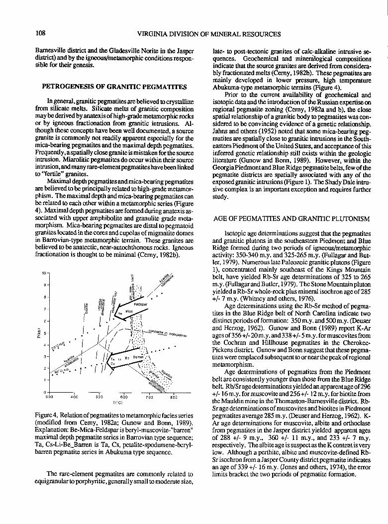
108 VIRGIMA DIVISION OF MINERAL RESOT.JRCES
Barnesville disrict and the Gladesville Nsite in the Jasperdisrict) and by the igneous/meamorphic conditions respon-sible for their genesis.
PETROGENESIS OF GRANTTIC PEGMATITES
In general, granitic pegmatites are believed to crysallizefrom silicate melts. Silicate melts of granitic compositionmay be derived by anatexis of high-grade metamorphic rocksor by igneous fractionation from granitic intrusions. Al-though these concepg have been well documented, a sourcegranite is commonly not readily apparent especially for themica-bearing pegmatite,s and the maximal depth pegmatites.Frequently, a spatially close granite is mistaken for the sourceintrusion. Miarolitic pegmatites do occur within their sourceintrusion,andmanyrare-elementpegmatites havebeen linkedto'fertile" granites.
ldaximal depth pegmatites and mica-bearing pegmatitesare believed to be principally related to high-grade metamor-phism. The maximal depth and mica-bearing pegmatites canbe related to each other within a methmorphic series (Figure4). Maximal depttr pegmatites are formed during anatexis as-sociated with upper amphibolite and granulite grade meta-morphism. Mica-bearing pegmatites are distal to pegmatoidgranites located in the cores and cupolas of migma'tite domesin Barrovian-type metamorphic terrain. These granites arebelieved to be anatectic, near-autochthonous rocks. Igneousfractionation is thought !o be minimal (Cerny, 1982b).
600T('C)
Figure4. Relation ofpegmatites to metamorphic facies series(modified from Cemy, I982a: Gunow and Bonn, 1989).Explanation: Be-Mica-Feldspar is beryl-muscovite-"barren"maximal depth pegmatite series in Barrovian tlpe sequence;Ta, Cs-Li-Be_Barren is Ta, Cs, petalite-spodumene-beryl-barren pegmatite series in Abukuma type sequence.
The rare-element pegmatites are commonly related toequigranular to porphyritic, generally small to moderate size,
late- to post-tectonic granites of calc-alkaline intrusive se-quences. Geochemical and minerilogical compositionsindicate that the source granites are derived from considera-bly fractionated melts (Cerny, 1982b). These pegmatites aremainly developed in lower fnessure, high temperatureAbukuma-type metamorphic terrains (Figure 4).
Prior to the current availability of geochemical andisotopic data and the infoduction of the Russian expertise onregional pegmatile zoning (Cerny, 1982a and b), the closespatial relationship of a granitic body o pegmatites wzls con-sidered to be convincing evidence of a genetic relationship.Jahns and others (1952) noted that some mica-bearing peg-matites are spatially close lo granitic intrusions in the South-eastern Piedmont of the United States, and accepunce of ttrisinfened genetic relationship still exists within the geologicliterature (Gunow and Bonn, 1989). However, within theGeorgia Piedmont and Blue Ridge pegmatite belts, few of thepegmatite disficts are spatially associated with any of theexposed granitic intrusions (Figure 1). The Shady Dale intru-sive complex is an important exception and requires fur*rerstudy.
AGE OF PEGMATITES AND GRANITIC PLUTOMSM
Isotopic age determinations suggest that the pegmatitesand granitic plutons in the southeastern Piedmont and BlueRidge formed during two periods of igneous/metamorphicactivity: 350-340 m.y. and 325-265 m.y. (Fullagar and But-ler, 1979). Numerous late Paleozoic granitic plutons (Figure1), concentrated mainly southeast of the Kings Mountainbelt, have yielded Rb-Sr age determinations of 325 ta 265m.y. (Fullagarand Butler, 1979). The Stone Mountain plulonyielded a Rb-Sr whole-rock plus mineral isochron age of 285+l- 7 m.y. (Whitney and others, 1976).
Age determinations using the Rb-Sr method of pegma-tites in the Blue Ridge belt of North Carolina indicate wodistinct periods of formation: 350 m.y. and 500 m.y. (Deuserand Herzog, 1962). Gunow and Bonn (1989) report K-Arages of 356+/- 20 m.y. and338 +/- 5 m.y. formuscovites fromthe Cochran and Hillhouse pegmatites in ttre Cherokee-Pickens district. Gunow and Bonn suggest that these pegma-tites were emplaced subsequent, to or near the peak of regionalmetamorphism.
Age determinations of pegmatites from the Piedmontbelt are consistently younger than those from the Blue Ridgebelr Rb/Sr age determinations yielded an apparent age of 296+/- 16 m.y. formuscovite and256+/- 12m.y.forbiotite fromthe Mauldin mine in the Thomaston-Barnesville district. Rb-Sr age determinations of muscovites and biotites in Piedmontpegmatites average 285 m. y. @euser and Herzog, I 962). K-Ar age determinations for muscovite, albite and orthoclasefrom pegmatites in the Jasper district yielded apparent agesof 288 +l- 9 m.y., 3ffi +/- 1l m.y., and,233 +l- 7 m.y.respectively. The albite age is suspect as the K content is verylow. Although a perthite, albite and muscovite-defined Rb-Sr isochron from a Jasper County district pegmatite indicatesan age of 339 +/- 16 m.y. (Jones and others, 1974), the errorlimits bracket the two periods of pegmatite formation.
6
J: 5
300 800
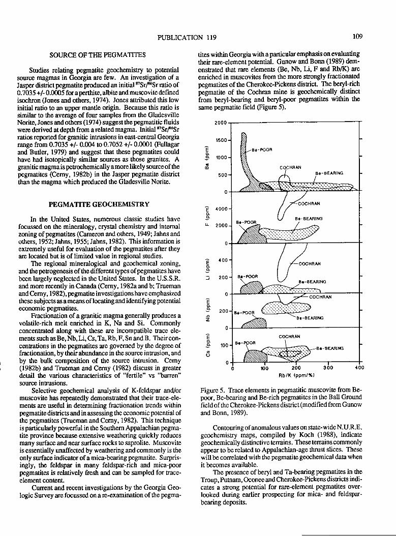
PUBLICATION I19 109
SOURCE OF THE PEGMATITES
Studies relating pegrnatite geochemistry to potentialsourice magmas in Georgia are few. An investigation of aJasper disrictpegmatite produced an initial eSrl6Sr ratio of0.7035 +/- 0.0005 fu aperthite, albite and muscovite definedisochron (Jones and others, 1974). Jones attributed this lowinitial ratio to an upper mantle origin. Because this ratio issimilar to the average of four samples from the GladesvilleNorite, Jones and others (1974) suggest the pegmatitic fluidswere derived at depth from a related magma. Initial nSrf6Sr
ratios reported for granitic intnasions in east-central Georgiarange from 0.7035 +/- 0.004 to0.7052+/- 0.0001 @ullagarand Butler, 1979) and suggest that these pegmatites couldhave had isotopically similar sources as those granites. Agranitic magmais petrochemically amorelikely source of thepegmatites (Cerny, 1982b) in the Jasper pegmatite disrictthan the magma which produced the Gladesville Norite.
PEGMATITE GEOCHEMISTRY
In the United Saes, numerous classic studies havefocussed on the mineralogy, crystal chemistry and internalzoning of pegmatites (Cameron and others, 1949; Jahns andothers, 1952; Jahns, 1955; Jahns, 1982). This information isextremely useful for evaluation of the pegmatites after theyare located but is of limited value in regional studies.
The regional mineralogical and geochemical zoning,and 0reperogenesis of the differenttypes of pegmatites havebeen largely neglected in the United States. In the U.S.S.R.and more recently in Canada (Cerny, 1982a and b; Truemanand Cerny, 1982), pegmatite investigations have emphasizedthese subjects as ameans of locating andidentifyingpotentialeconomic pegmatites.
Fractionation of a granitic magma generally produces avolatile-rich melt enriched in K, Na and Si. Commonlyconcentrated along with these are incompatible trace ele-ments such as Be, Nb, Li, Cs, Ta, Rb, F, Sn and B. Their con-centrations in the pegmatites are govemed by the degree offractionation, by their abundance in the source intrusion, andby the bulk composition of the source intrusion. Cerny(1982b) and Trueman and Cerny (1982) discuss in greaterdetail the various characteristics of "fertile" vs "barren"source intrusions.
Selective geochemical analysis of K-feldspar and/ormuscovite has repeatedly demonstrated that their trace-ele-ments are useful in determining fractionation rends withinpegmatite districts and in assessing the economic potential ofthe pegmatites (Trueman and Cerny, 1982). This techniqueisparticularly powerful in the Southern Appalachian pegma-tite province because extensive weathering quickly reducesmany surface and near surface rocks to saprolite. Muscoviteis essentially unaffected by weathering and commonly is theonly surface indicator of a mica-bearing pegmatite. Surpris-ingly, the feldspar in many feldspar-rich and mica-poorpegmatites is relatively fresh and can be sampled for trace-element content.
Current and recent investigations by the Georgia Geo-logic Survey are focussed on a re-examination of the pegma-
tites within Georgia with a particular emphasis on evaluatingtheir rare-element potential. Gunow and Bonn (1989) dem-
onsEated that rare elements (Be, Nb, Li, F and Rb/K) are
emiched in muscovites from the more strongly fractionatedpegmatites of the Cherokee-Pickens disrict. The beryl-richpegmatite of the Cochran mine is geochemically distinctfrom beryt-bearing and beryl-poor pegmatites within the
same pegmatite field (Figure 5).
2000
1500
?o._o 1000a
500
0
,1000
2000
0
Rb/K (ppm/x)
Figure 5. Trace elements in pegmatitic muscovite from Be-poor, Be-bearing and Be-rich pegmatites in the Ball Groundfield of the Cherokee-Pickens district (modified from Gunowand Bonn, 1989).
Contouring of anomalous values on state-wide N.U.R.E.geochemistry maps, compiled by Koch (1988), indicategeochemically distinctive terrains . These terrains commonlyappear to be related to Appalachian-age thrust slices. Thesewill be correlated with thepegmatite geochemical data whenit becomes available.
The presence of beryl and Ta-bearing pegmatites in theTroup, Putnam, Oconee and Cherokee-Pickens disricts indi-cates a sfiong potential for rare-element pegmatites over-looked during earlier prospecting for mica- and feldspar-bearing deposits.
co.
L
? 400co.
-o: 200
Eo
z
coao
110 VIRGIMA DIVISION OF MINERAL RESOURCES
SI.JMMARY
Initially mined for sheet mica, pegmatites in Georgiahave also been important sources of feldspar, "scrap" mica,and beryl. Preliminary results of current investigations by theGeorgia Geologic Survey, suggest that the economic poten-tial for pegmatites has not been realized in Georgia.
Most pegmatites occur within twelve distinct disrictswhich form the Blue Ridge and Piedmont belrs of the Appa-lachian pegmatite province. These districts , generally are notspatially related to exposed granitic inrusions, thereby sug-gesting that the origin of the pegmatites is more closelyrelated to regional scale metamorphism and anatexis.
Isotopic age determinations of granites and pegmatitesindicate that they did form during the same nvo periods.Genesis and emplacement of the granitic intrusions, regionalscale metamorphism and anatexis may thus be broadly re-lated. The Blue Ridge belt granites and pegmatites appear tobe older than the Piedmont belt innusions.
Fractionation of rare-elements during pegmatite genesiscan be identified through geochemical analysis of muscoviteand,/or K-feldspar. Current investigations are focussed onthis use of ftace-element geochemistry to determine regionalzoning relations and evaluate poorly exposed pegmatites.
REFERENCES CITED
Beck, W.A., 1948, Georgia mica spots, Cherokee, Upson,Iamarand Monroe Counties, United States Bureau of MinesReport of Investigations4239,29 p. plus figures.
Cameron, 8.N., Jahns, R.H., McNair, A. and Page, L.R.,1949, Internal structure of granitic pegmatites: EconomicGeology Monograph 2, 115 p.
Cameron, W.L., and Sparks, L.,1976, Feldspar deposis ofthe Glade,sville Norite: Twelfth Forum on the Geology ofIndusrial Minerals, Georgia Geologic and Water ResourcesDivision (abstract).
Cerny, P., 1982a, Anatomy and classification of graniticpegmatites: in Cemy, P. (ed.), Short Course in GraniticPegmatites in Science and Industry, Mineralogical Associa-tion of Canada, v. 8, p. 140.
Cerny, P., 1982b, Petrogenesis of granitic pegmatites: izCerny, P. (ed.), Short Cornse in Granitic Pegmatites inScience and Industry, Mineralogical Association of Canad4p.405462.
Clarke, J.W., 1952, Geology and mineral resources of theThomaston quadrangle, Georgia: Georgia Geologic SurveyBulletin 59, 103 p.
Cook, R.B., 1978, Minerals of Georgia - their properties andoccunences: Gecgia Geologic Survey Bulletin 92, 189 p.
Deuser, W.G., and Herzog, L.F., 1962, Rubidium-Srontiumage determinations of muscovites and biotites of the Blrrc
Ridge andPiedmont, Journal of Geophysical Research, v. 67,p. 1998-2003.
Fullager, P.D., and Butler, RJ., 1979, 325 tD265 M.Y.-oldgranitic plutons in the Piedmont of the southeastem Appala-chians, American Journal of Science, v.279,p. 161-185.
Furcron, A.S., 1959, Beryl in Georgia: Georgia MineralNewsletter, v. 12, no. 3, p. 91-95.
Furcron, A.S., and Teague, K.H., 1943, Mica-bearing peg-matites of Georgia: Georgia Geological Survey Bulletin 48,r92p.
Galpin, S.L., 1915, A preliminary report on the feldspar andmica deposirs of Georgia: Georgia Geologic Survey Bulletin30, 190 p.Ginsburg, A.I., Tinofeyev, I.N., and Feldman, L.G., 1979,Prirrciples of geology of the granitic pegmatites: NedraMoscow,296 p.
GriffiEs, W.R., and Olson, J.C., 1953, Mica deposits of theSoutheastem Piedmont, Part 7, Ilartwell district, Georgia andSouth Carolina: United Sates Geological Survey Profes-sional Paper 248-F,, p. 293 -316.
Gunow, AJ., and Bonn, G.N., 1989, The geochemisury andorigin of pegmatites Cherokee-Pickens district, Georgia:Geogia Geologic Survey Bulletin 103, 93 p.
Flanley, T.8., 1986, Perography and srucnral geology ofUctpe belt rocks in Columbus, Georgia and Phenix City, Ala-bama: Geological Society of America Centennial Field Guide,Southeastem Section, v. 6, p. 297-300.
Heinrich, E.W., Klepper, M.R., and Jahns, R.H., 1953, Micadeposic of the Southeastern Piedmont" Part 9. Thomaston-Barnesville District, Georgia and Part 10. Outlying Deposisin Georgia: United States Geological Survey ProfessionalPaper 248F, p.3274ffi.
Hewett DF., andCrickmay, G.W., 1937, TheWarm Springsof Georgia, their geologic relations and origin, a summaryreport United States Geological Survey Water Supply Paper819,40 p.
Higgins, M.W., Atkins, R.L., Crawford, T.J., Crawford, R.F.,III, Brooks, R., and Cook, R.8., 1988, The structure, strati-graphy, tectonostratigraphy, and evolution of the southern-most part of the Appalachian trogen: United States Geologi-cal Survey Professional Papr 1475, L73 p.
Hooper, RJ., 1986, Geologic studies at the East end of thePine Mountain Window and adjacent Piedmont, CenralGeagia: Unpublished report for the Georgia Geologic Sur-vey, Conftact Number 7 0l-39O148, 322 p.
Hurst, V.J., and Crawford ,T J., I9&, Exploration for min-eral deposits in llabersham County, Georgia: Georgia Geo-logic Survey Reprint Series, 180 p.
PUBLICATION 119 11r
Hurst, VJ., and Otwell, W.L., 1964, Exploration for mineraldeposis in White County, Georgia: Georgia Geologic Sur-vey Reprint Series, 166 p.
Jahns, R.H., 1955, The study of pegmatites: Economic Geol-ogy,50th Anniversary Volume - 1955, p. 1025-1130.
Jahns, R.H., 1982, Internal evolution of granitic pegmatites,
ln Cerny, P. (ed.), Short Course in Granitic Pegmatites inScience and Industry: Mineralogical Association of Canada,p.463494.
Jahns, R.H., Griffitts, W.R., and Heinrich, E.W., 19 52, MicaDeposits of the Southeastern Piedmont" Part 1. General Fea-tures: United States Geological Survey Professional Paper248-4,p. 1-102.
Jones, L.M., Carpenter, R.H., and Whitney, J.4., 1974,Rubidium-Srontium age and origin of the pegmatites associ-ated with the Gladesville norite, Jasper County, Georgia:Geological Society of America Southeastern Section Meet-ing Absracts with Programs, v. 6, No.4, p. 369.
Koch, G.S., Koch, R.S., and Kapatov, A., 1984 and 1987,Geologic Atlas of Georgia - An atlas of mine workings,quarries, and prospects in part ofnorthern Georgia: GeorgiaGeologic Survey Open File Atlas, on open file, 7.5-minutequadrangle maps and unpaginated listings.
Koch, G.S., 1988, A geochemical atlas of Georgia: GeorgiaGeologic Survey Geologic Atlas,42 pl.
lvlatthews, III, V., 1967, Geology and petrology of the peg-
matite district in southwestern Jasper County, Georgia:University of Georgia, unpublished M.S. thesis,68 p.
Reno, H.C., 1956, Beryllium, jg Minerals Facts and Prob-lems: U.S. Bureau of Mines Bulletin 556, p. 95-102.
Schamel, S., Hanley, T.B., and Sears, J.W., 1980, Geologyof the Pine Moun[ain Window and adjacent tenanes in thePiedmont Province of Alabama and Georgia: GeologicalSociety of America Guidebook The Geological Society ofAmerica 29ttr Annual Meeting, p. 1-69.
Trueman, D.L., and Cerny, P., 1982, Exploration for rare-element granitic pegmatites: in Cemy, P. (ed.), ShortCoursein Granitic Pegmatites in Science and Indusfy, Mineralogi-cal Association of Canada, v. 8, p. 463494.
White, W.H., Bmkstrom, A.A., Kamilli, RJ., Ganster, M.W.,Smith, R.P., Ranta, D.E., and Steiniger, R.C., 1981, Charac-ter and origin of Climax-Type molybdenum deposits: inSkinnner, BJ., Economic Geology Seventy-Fifth Anniver-sary Volume,p.270-316.
Whitlach, G.I.,l962,Georgia's Mineral Resources: A sum-
mary of available daa on tlreir past, present and future status:Geugia Institute of Technology publication, 130 p.
Whiurey, J.A., Jones, L.M., andWalker, R.L., 1976, Age and
origin of the Stone Mountain granite, Lithonia District,Georgia: Geological Society of America Bulletin, v. 82, p'2827-2844.

t12 VIRGINIA DIVISION OF MINERAL RESOURCES
PUBLICATION 119
A RE.EVALUATION OF THE TAXONOMY OF NEWARK SUPERGROUPSAURISCHIAN DINOSAUR TRACKS, USING EXTENSWE STATISTICAL DATA
FROM A RECENTLY EXPOSED TRACKSITE NEAR CULPEPER, VIRGINIA
RobertEWeemsMail Stop 928
U.S. Geological SurveyReslon, Ytrginna220f2
r13
ABSTRACT
An Upper Triassic bedding surface, recently exposed inthe Culpeper Stone Company, Inc. quarry, has revealed about2,000 reptile tracfts. About 1,500 of these tracks, anayed in20 rackways, probably represent a single biological species
of ridactyl bipedal dinosaur. Critical measurements of 243of the best preserved tracks have established the range ofmorphological variability within single trackways and pro-vided limits of reliability (LOR) for using ichnospecies ofblpeAA dinosaur fmtprints to estimate biological species
diversity. These LOR are an important method of evaluatingpreviously described ichnospecies of dinosaur fooprints inthe Newark Supergroup of eastern North America. Thisevaluation suggests that eadier workers overinterpreted subtledifferences among fracks. Of 7 ichnogenera and 23 ichnospe-cies of tridactyl saurischian dinosaur tacks described previ-ously from theNewark Supergroup, only 3 ichnogenera and8 ichnospecies can be consistently recognized. The rest fallinto therange of morphological variability exhibited by these
8 ichnospecies. Kayentapus hopii fromArizona represents aninth closely related valid ichnospecies.
INTRODUCTION
Recent quarrying by the Culpeper Stone Company, Inc.has uncovered footprints on a bedding suface in the BallsBluff Siltstone about 130 feet below a previously discoveredfooprint-bearing surface described by Weems (1987). Thegeologic setting of the newly discovered surface is in manyways similar to the previously described surface. Both are ontop of massive, calcareous cemented siltstone beds. The mostabundantbedding features on these surfaces areripple marks,fooprints, and mudcracks recording the progressive dryingof a mudflat along a lake margin. In both cases, afterprolonged drying which hardened the mud, an influx of waterinto the lake probably caused it to expand and rapidly coverthe exposed margin so that the footprina and other beddingfeatures were preserved intact. Initially, only calcium car-bonate was deposited on the fooprint-bearing surfaces. Inthe case of the previously described layer, much of thecarbonate was rolled into oolitic pellets which occur inpatches across the track-bearing surface (Young and Edmund-son, 1954 ; Carro zi, 1964). In the case of ttre newly discoveredlayer, the carbonate was broken but not rolled, so that frag-ments of stromatolites, tufa tubes, and conchostracan or mol-luscan bivalve shells were deposited in patches across the
track-bearing surface. Two bone fragments, a parasuchian
looth, and fish scales have been found within the carbonatepatches. The nacks and carbonate deposits on both rack-bearing surfaces subsequently were covered by one to three
feet of well laminated gtay shale, representing lacusEinedeposition. So far, fish scraps have not been found in the gray
shale.The prints in the upper layer were less distinct but
relatively more diverse and numerous, being densely concen-trated over much of the exposed surface. However, because
much more of the lower layer has been exposed the totalnumber of prints found on the lower layer (about 2,000)greatly exceeds the number found on ttre upper layer (about
830 in recognizable trackways). The lower layer, whichincludes numerous tracks of high quality, may be the mostextensively exposed Triassic dinosaur trackway beddingplane in the world (compare to Gillette and Inckley, 1989).
CHALLENGES OF FOOTPRINT TAXONOMY
A good naturalist can use tracks and trackways of mod-em animals to estimate their abundance and diversity in areas
where sitings are uncommon. In theory, this apprmch can be
ap'plied o prehistoric communities as well. Apaleoichnolo-gist should be able to extract much diverse information on
terrestrial faunas from examination of tracksites on beddingplane,s. In practice, however, modern naturalists do notencounter two obstacles that commonly hinder paleoichnolo-gists. The first obstacle is that extensive trackway exposures
on bedding planes are rare. Usually a small area of a beddingplane with perhaps a few nacks is aU that is found, and oftenthese are on isolated blocks of rock, out of their originalstratigraphic context. The Culpeper Stone Company, lnc.quarry represents a remarkable exception to t}is, because itexposes an unusually large surface of a lacustrine shorelinemudflat and looks much as it did only days after Triassicanimals crossed it.
A second obstacle confionting paleoichnologists, espe-
cially pre-Cenozoic specialists, is that the nature and diver-sity of the animals that left tracks at a given site often are
unlnown. In a modern setting, naturalists have a good
(perhaps perfect) knowledge of what animals exist in an arca
and what they look like. This information usually is lackingfor animals that made fossil Fackways. Thus paleoichnolo-gists are compelled to use Eacks u prinn facie evidence
rather than as secondary aids for estimating abundance and
diversity of animals that are already known. Althoughfooprints of an individual animal are preserved differently indifferent settings (depending on the speed and gait of the
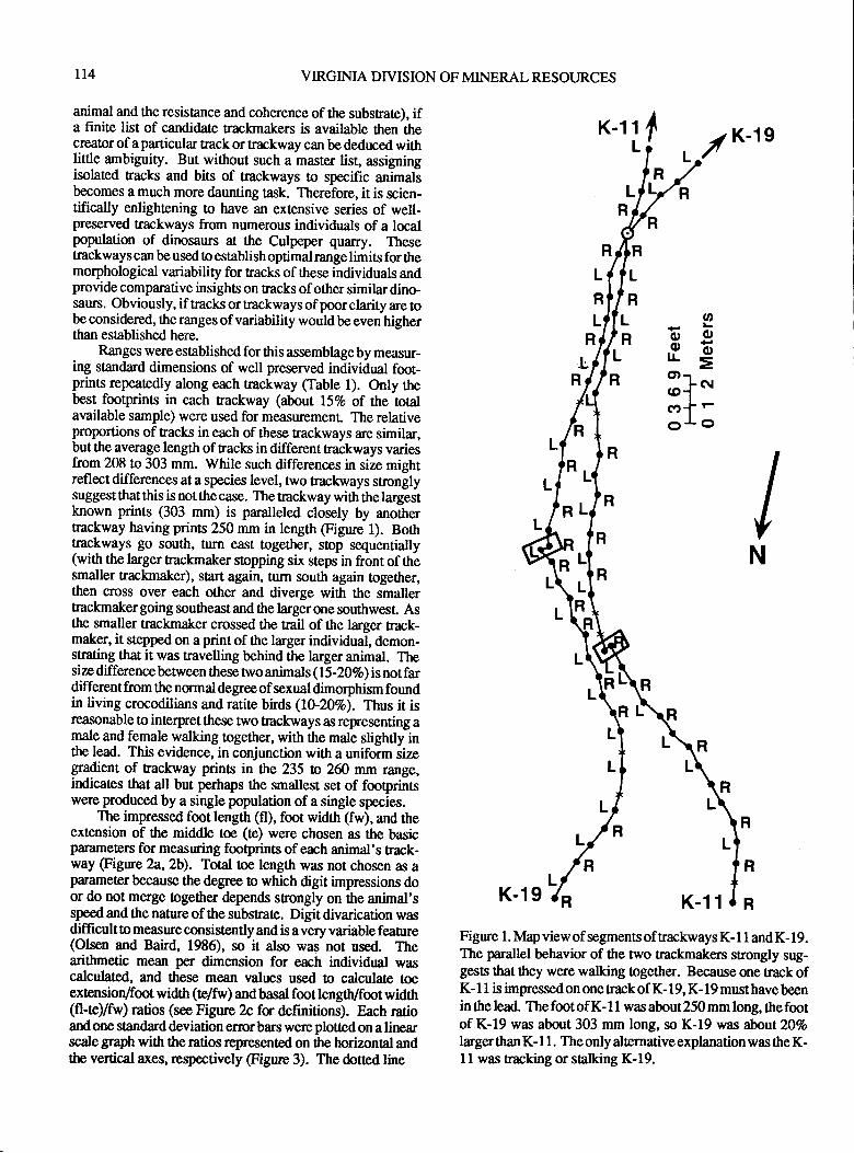
t14 VIRGINIA DIVISION OF MINERAL RESOURCES
animal and the resistance and coherence of the substrate), ifa finite list of candidate trackmakers is available then thecrcator of aparticular track or fiackway can bededuced withlittle ambiguity. But without such a master list, assigningisolated tacks and bits of trackways lo specific animalsbecomes a much more daunting task. Therefore, it is scien-tifically enlightening to have an extensive series of well-preserved Eackways from numerous individuals of a localpopulation of dinosaurs at the Culpeper quarry. Thesetrackways can be used o establish optimal range limirs fon themorphological variabiliry for tracks of these individuals andprovide comparative insights on tracks of other similar dino-saurs. Obviously, if tracks or trackways of poor clarity are obeconsidered, the ranges of variability wouldbe even higherthan established here.
Ranges were established for this assemblage by measur-ing standard dimensions of well preserved individual foot-prints repeatedly along each trackway (Table l). Only ttnbest footprints in each fiackway (about l57o of the totalavailable sample) were used for measuremenL The relativeproportions of tracks in each of these trackways are similar,but the average length of tracks in different kackways variesfrom 208 to 303 mm. While such differences in size mightreflect differences at a species level, two ftackways stnonglysuggest that this is not the case. The fiackway with the largestknown prints (303 mm) is paralleled closely by anotherEackway having prints 250 mm in length @gure 1). Borhtrackways go south, Urrn east togetler, stop sequentially(with the larger trackmaker stopping six steps in front of thesmaller trackmaker), start again, turn south again together,then cross over each other and diverge with the smallertrackmaker going southeast and the larger one southwesl Asthe smaller trackmaker crossed the trail of the larger rack-maker, it s0epped on a print of the larger individual, demon-smting that it was travelling behind the larger animal. Thesize differencebenveen these nvo animals (15-202o) is notfardifferent from the normal degree of sexual dimorphism foundin living crocodilians and rarite birds (10-202o). Thus it isreasonable to interpret these two trackways as representing amale and female walking together, with the male slightly inthe lead. This evidence, in conjunction with a uniform sizegradient of trackway prints in the 235 tn zffi mm range,irdicates that all but perhaps the smallest set of fooprintswere produced by a single population of a single species.
The impressed fmt length (fl), foot width (fw), and theextension of the middle toe (!e) were chosen as the basicparameters for measuring fmtprints of each animal's track-way (Figure 2a,2b). Total toe length was not chosen as aparameter because the degree o which digit impressions door do not merge together &pends strongly on the animal'sspeed and the nature of the subsrate. Digit divarication wasdifficult o measure consistently and is a very variable feaure(Olsen and Baird, 1986), so it also was not used. Thearithmetic mean per dimension for each individual wascalculated, and these mean values used to calculate toeexlensiory'foot width (te#w) and basal foot lengtly'fmt widttr(fl-te)/fw) ratios (see Figure 2c for definitions). Each rarioandone sAndarddeviation errorbars were plotted on alinearscalegraph with theratios represented on the horizonal andthe vertical axes, respectively @gure 3). The dotted line
IK-11L
fiL
o
F*E=
CDrr{*cDf -o!o
IN
L
L
R
R
y'K-1s
R
L
R
LR
K-19 K-11
Figure 1. Map view of segments of rackways K- I 1 and K- 19.The parallel behavior of the two trackmakers sEongly sug-gests that they were walking together. Because one track ofK- I I is impressed on one track of K- I 9, K- 1 9 must have beenin the lead. The foot of K- 1 I was about 250 mm long, the footof K-19 was about 303 mm long, so K-19 was aboat}}%olarger than K- I 1. The only alternative explanation was the K-11 was tracking or stalking K-19.
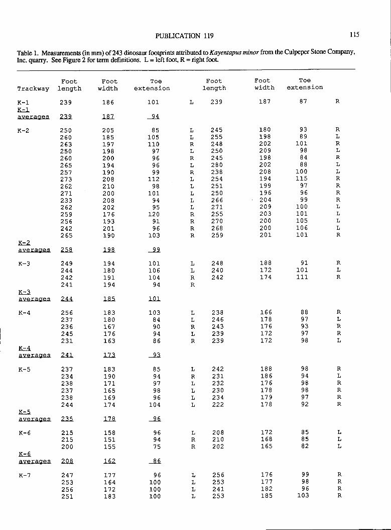
PLIBLICATION 119 115
Table 1. Measurements (in mm) of 243 dinosaur footprinB attributed to Koyentapus minor ftom the Culpeper Stone Company,Inc. quarry. See Figure 2 for term definitions. L = left foot, R = right foot
Trackway
K-l_K-1averag:es
K-2
K-2averages
K-3
K-3averages
K-4
K-4averages
K-5
T{- R
averages
K-6
K-6averages
K-7
Footlength
239
239
2502602632s0260265257273262271-2552622592s6242265
258
24924424224L
244
256237236245231.
24t
237234256237238244
235
2152r5200
208
24725325625L
Footwidth
r.8 6
L87
205185LYIr.982001941902082L0200208202l./bL9320t190
r_98
19418019r.194
l nq
'l R?
180167j-76153
173
L83190171165169Ltq
11Q
1CQ
1_5 1155
r62
177]-64I721R?
Toeextension
r.0 r_
94
85105110
9lvovo99
rL298
10194
t209196
103
r.01J-UO
r.0 494
1n1
1n?84909486
94vt9896
r_04
9694
vbl_0 0100r.0 0
Footlength
239
24525s248250245280238254z>L250zoo2"t1-255270268259
Footwidth
r-87
r_8 0
198202209L98202208t94199rvb204209203200200zvL
Toeextension
87
9389
101988488
1_00
Lr597OA
99100101105106101
LLt{,
Lt(
LRTLLLL
Rt(R
RLt(TRLLRRRRLLL
n
I,LRLR
LtlLLLL
RLn
LLRR
LLL
Aq
82
LRR
RRRR
LL!
L
248240242
238246243z5Y259
r_88t"t2t74
166178L16L72L72
188185l/o178L79178
t72r_6816s
1761,7 7t82IU5
r.0 L111
25625324t253
8897YJYIYU
989498989792
999896
l_03
K
LRRL
RLRt(RR
24223tzJz230234222
2082t0202
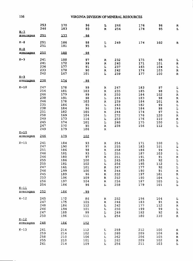
l16
253246
K-?averagres 251
K-8 25t25L
K-8
VIRGINIA DTVISION OF MINERAL RESOI'RCES
1?0183
L77
186181
180
180t72L77178t67
r74
178181L79191178185184t82169173I74170179
779
r.8 4190186181180185181151199189195rvt186
1R6
t72175196194r.8 8J-vb
146
2t42142102102L4
9693
98
98
97999190
101
98
99103
9998
1039596
105104r. r.5101
95r.0 5
ro2
939798YJ97
100t021n1
t_0 0
96r.0 9104
96
99
86105r]-2r.0 1
99111
]-02
tt2t02J.Ubr.01109
246254
249
t75t74
9695
R9895
LR
174 t02
averagres
K-9
K-9averages
K-t_0
K- 10averages
K-L1
K-1 1
averaoes
K-12
K-L2averages
K-13
250
24L24t236233240
238
24725624623824623523825L250249245247249
246
24L24725L24624625525s247246245255256254
252
245247248246247250
248
26r259258255261
232240237242239
175171155r-.74L77
95101104103100
LRLRR
RRL
R?u
RRRLRLLR!
RRRLRL?
RRRRRL
LI!
Rt(
RRLLLL
LLLLL
2472352s0244239243244244272253240238
25425525825525r2452s6247244252z5z2562s8
183185184183184L82184L74L76L76175156
r.7 1L83185r.8 7191185195177190r97190187t79
9798
L0298
101999897
L20110100tt2
100r_0 1
99103
9192
LI29291
10 r.
10410sr.01
L?
RRRLLLRRLL
LLLLRLLLRl(
LLL
LRRLRR
z5z246242250249254
259260262262256
-Lvb1n?t"t7199182180
2t22092062092Lt
10491
LL29992
1'!n
100106105L02103
RRt(RL
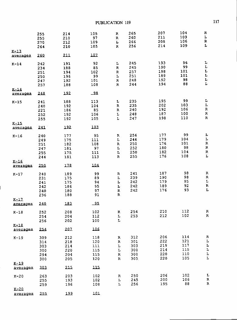
PUBLICATION 119 11?
K-13averages
K-14
K-14averages
K-15
K-15averages
K-16
K-t_ 6
averages
K-L7
255255270264
260
24223425L250247257
248
24L240227252255
241-
24024925l.247255244
250
24023L24L242240236
2142L02t22t0
UJ191188L94196r92188
192
188L92185L92t92
L92
]-17175L82181175181
1?8
189L75175186180188
183
208204202
20'l
2t22r82L4220204205
zL5
203r.93L96
199
10597
109r-0s
107
9285
70299
101108
q8
11?104
85106r.05
103
95L11108
97l_ 11113
104
998994959791
95
r027L2100
106
118]-201_11
115L20
115
L02L02108
1n1
2652602662s6
2072Ll2082L4
104109106109
9699
10l_101
9888
99103106100110
99104101
98104108
LRRtRR
RRLR
LRRLL
24524525725L248244
235235240248247
256246250252250255
193190198189L92L94
195202t92187198
I,LLLLt
RLRL
tLRRR
RRLRL
LRR
RLRLLR
241239242242242
L77t't9176180L82t't 6
187190L79L89].76
9898959Z93
LLRRRL
RLLLRR
K-1?averagres 240
K-18 252254256
K-18avera9tes
K-l 9
K-19averagies
K-20
K-20averages
RLL
l(LL
2542s3
2L02t2
LT2L02
254
309314303300294300
303
263255259
255
3t2301303?nn30030s
206222ZLY2t4220220
114t2t1-17
110105
t(t(LLRR
RLLLLL
250245256
206200195
t02L06
88

1r8 VIRGINIA DIVISION OF MINERAL RESOURCES
Figure 2. A. Outline drawing of a Grallator-l:ke dinosaur footprint showing ttre parameters of the foot measured for this srudy.fl = geatest foot length from rear pad of digit IV to the tip of ttre claw of digit III, as measured along ttre axis of the foot; fw =geatest foot width; te = extension of digit trI beyond a line drawn across the tips of digits II and IV, measured down the axis ofdigit III. B' Outline drawing of a Eubronteslike footprint, showing method of measurement used when the width of the padsof digia II and IV are wider than the tips of the claws. fw' = point at which fmt widttr is measured on this kind of rack. te stillisdeterminedfromalinedrawnacrossthetipsofdigitsllandlV(fu)asincaseA. C. OutlinedrawingofaGraltaror-likefootprintshowingthehvoratiosdeterminedfromthemeasuredparameters. Becauseteandflusuallyarenotquitemeasuredalongthesameline, fl-te is a close estimate of the line labelled fl-te rather than an exact measurement. These ratios basically define a footprintas two triangles, one facing anteriorly and one facing posteriorly.
BA
enclosing the composited values represents the minimummorphological range expected within this well preservedsingle population of tridactyl blpedal dinosaur footprints.The field defined by these mean values and error bars consti-tutes the minimum inherent variability that reasonably maybe expected within this population. If conditions ofpreserva-tion were less favorable, the fooprint measruements wouldhave less reliability than found here.
The mean values of the Culpeper quarry trackways(shown by X's in Figure 4) vary from 0.50 ro 0.58 for tefw,and from 0.71 to 0.87 for (fl-te)fw. Because these trackwaysyielded a considerable range of values, and because thesevalues presumably represent a single biological populationleaving prints made and preserved under exceptionally favor-able circumstance,s, it is improbable that closely related andmorphologically very similar biological species would leavetrackways that could be consistently differentiated. As thevariability documented here is a well supported minimumvalue for the variability that must be incorporated into thedefinition of a field-useful ichnospecies, it is therefore quiteprobable that closely related biological species with similarfoot proponions could not be consistently differentiated.
Forms with the same critical dimensions could be differenti-ated meaningfully only if they have other distinctive attrib-utes (such as differences in the number ofpads in the digits ordemonsEably different digit proportions or shapes that can-not be attributed to substrate effects). This supports Baird's(1957) contention that ichnospecies conespond roughly tobiological genera.
COMPARISONS WITH PREYIOUSLY DESCRIBEDBIPEDAL
NEWARK SUPERGROUP ICHNOSPECIES
Using these minimum limis of variability, the authorvisited the Pratt Museum at Amherst, College and measuredthe critical dimensions of type specimens of most tridactyl bi-pedal saurischian ichnospecies in that collection. OnlyEubrontes, tuberosus, Eubrontes approimatus, and Gralla-tor gracillis were not measured from the type specimens.Conesponding ratios based on these types were plotted in thesame manner as the Culpeper quarry prints (Figure 4) Opermit reasonable comparison. Specimens not available for
LI-\l -t!vj
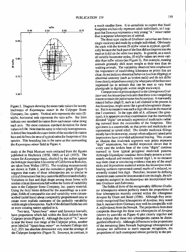
PUBLICATION 119 r19
Figure 3. Diagram showing the mean ratio values for twenty
trackways of Kayentapus minor in the Culpeper Stone
Company,Inc. quarry. Vertical axis represents the ratio (fl-te)/fw, horizontal axis represents the ratio te/fw. Bar lines
indicate one standard deviation from each mean value along
each axis. The most common standard deviation for these
values is 0.04. Note that the array is relatively homogeneous.
A dotted line bounds the outer limits of the standard deviation
bars and defines the area oftypical ratios for footprints ofthisspecies. This bounding line is the same as that surroundingthe Kayentapus minor field in Figure 4.
study at ttre Prau Museum were extracted from the figurespublished in Hirchcock (1858, 1865) or Lull (1953). Thevalues for Kayentapus lapii, checked by the author againstthe holotype material at University of California at Berkeley ,
are taken from Welles (1971). The resulting measuementsare shown in Table 2, and the cumulative graph (Figure 4)suggests that many of these ichnospecies are so similar incritical dimensions that they cannotbe differentiated reliably.Variations in foot and digit shape among those forms withsimilarcritical dimensions fall within the limis of variabilityseen in the Culpeper Stone Company, Inc. quarry material.Using the field limis defined by the assemblage as a tem-plate, fields of comparable size and variability were circum-scribed (solid linas) about comparably proportioned taxa ocreate more realistic estimates of the probable variabilitywithin single ichnospecies. Each of the defined fields has oneor more existing names applied to ir
Two taxa, 'Apatichnu" minor and Stenonyx lateralis,have proportions which fall within the field defined by theCulpeper prins (Figure 4). Although the type of "A." miiloris near the lower size range of the Culpeper prints, anotherprint labelled "Apatichnw minar" on Amherst College slabA.C.25ll has absolute dimensions very near the average ofthe Culpeper footprints (Figure 5). Stenonyr, in conrast, is
a much smaller form. It is unrealistic to expect that fossil
footprints exclusively represent adult individuals, so I sug-
gestihat Sten onyx r epresents a very youn g " A-" minor ralher
than a separate ichnospecies of animal.Theihree type tracks of Grallator cwsorius are from a
single nackway and made by a single individual. Obviouslythe track with the lowest (fl-te)/fw value is atypical, specifi-
cally because the back part of the foot did not impress into ttre
mud as it did on the other two Eacks. In general, as a result
of variable locomotor styles, (fl-te)/fiv values are more vari-able than tefw values (see Figure 3). For example, running
animals generally shift more weight to their oes ttran do
walking animals. The variability observed here emphasizes
the importance of establishing ichnotaxa on prints that are
clear, do not indicate abnormal behavior (such as slipping) orabnormal anatomy (such as broken nails) and do not differfrom closely related taxa simply by what parts of the foot were
impressed (as in animals that can be seen to vary fromplantigrade to digitigrade within single trackways).-
Comparisons ofprints assigned to the ichnogenera Gratlabr and Anchisauripus indicates that there is no compellingreason to re[ain thejuniorname Anchisaurlpzs. A rearwardly
rotated hallux (digit I), such as Lull claimed to be present inAnchisauripus, mightseem like a good ichnogeneric charac-
ter. B ut in no instance was such a digit obvious in the material
that I examined. In the type slab of A. sillimani (the geno-
type), it is apparent on close examination that ttre rearwardlydirected "digits" are actually segments of mudcracks radiat-ing outward from the extremities of the footprints. This
specimen is a counterslab, so that prints and mudcracks are
represented in raised relief. The slender mudcrack fillingsmostly have broken away, except where adjacent raised printimpressions have provided additional bracing. This creates
an illusion ttrat mudcrack segments near prints represent
"digit" impressions, but careful inspection shows that inevery case the broken base of the extra "drgits" continueoutward to form typical polygonal mudcrack patterns.
Alttrough Gigandipus caudatus does clearly possess a mod-
erately reduced and mesially rotated digit I, in no ins[ance
was there clear or convincing evidence ttrat any of the smallnicks and depressions scattered across Anchi sauripus f:ack'bearing surfaces represented toenail marks of a reduced, re-
arwardly rotated first digit. Therefore, because its defining
character state cannot be demonstrated convincingly, the ich-nospecies assigned n Anchisauripzs are incorporated here
into G r al lat or and E ubr o nt e s.The fields of three of the recognizably different Gralla'
tor ichnospecies almost perfectly match the proportions offour ichnospecies recently erected within the ichnogenus
Atreipus by Olsen and Baird (1986). Altttough they tenta-
tively recognized four ichnospecies of Atreipus, they noted
tlmtt A. nrctircri from Germany may well be conspecific witttA. milfordensis from the Newark. The proportions from theircomposite drawings for these two ichnospecies of. Atreipus(shown by asterisks on Figure 4) plot closely together and
thus indicate that these two ichnospecies cannot be distin-guished effectively. Although differences in the proportions
of the remaining three Newark Supergroup ichnospecies ofAtreipus are sufficient to merit separate recognition, the
proportions of each correspond almost perfectly to the pro
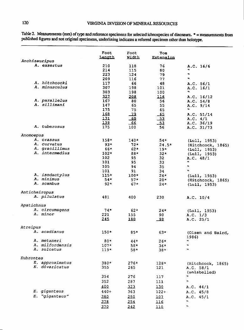
I2O VIRGINIA DIVISION OF MINERAL RESOURCES
Table 2. Measurements (mm) of type and reference specimens for selected ichnospecies of dinosaurs, * = measurpments from
published figures and not original specimens, underlining indicates a referred qpecimen other than holotype.
AncllisauripusA. exsertus
A. hitchcockiA. minuscufus
A. paralJelusA. si]l.imani
A. tu.berosus
AnomoepusA. crassusA. curvatusa. gracillimusA. intermedius
A. isodactyLusA. minimusA. scambus
AnticheiropusA. pilulatus
ApatichnusA. circumagensA. minor
AtreipusA. acadianus
A. metzneriA. milfordensisA. su-Lcatus
EubrontesE. approximatusE. divaricatus
E. giganteusE. "giganteus"
FootLength
2t02L4223209l_17307303327L67r47175168131139175
158 *g3*66*
t02*t021011051011 15*54*92*
481
74*22t245
150 *
80*107 *119*
380*3s5
3543s2400440+3803783?0
footwidrh
118115L24116
66198198208
806575796066
100
140 *72*62r,88*95959491
100 *57*67't
400
62t,155180
g5*
44*58*58*
27 6*265
2752873233632s0254242
ToeExtension
7680797748
101100116
5655656553s356
54*24.5*1g*32t3233353426*20r,24*
230
24*9098
63*
26*36*3g*
12g*t27
11?Lt1130122+1071l- 611n
1.". L6 / 6
A.C.56/LA.C. L6/t
A.C. L6/L2A.C.54/8A.C.9/L4
A.C. 5L/L4A.C. 4/tA.C.36/19A.C.3L/73
(LuIl, 1953)(Hitchcock, 1 8 65 )(LuIL,1953)(LuII,1953)
I " 48/L
(Lull, 1953)(Hitchcock, 18 65 )(LulI,1953)
A.C. r0/4
(LuIl,1953)A.C. t/3A.C.25/L
(Olsen and Baird,1986)
(Hitchcock, 1865)A.C.58/L(unlabelled)
A.C.44/rA.C. 45/8A.C. 45/t
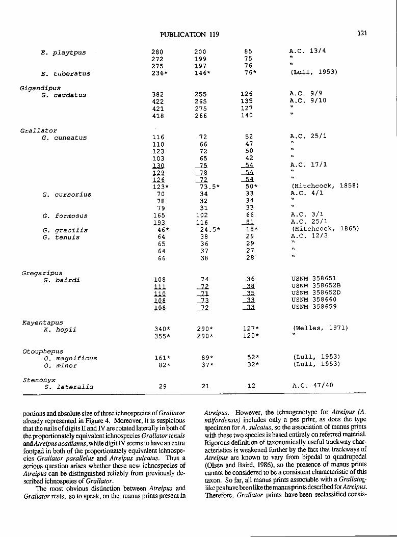
PUBLICATION II9 tzl
E. playtpus
E. tuberatus
GigandipusG. caudatus
GraIIatorG. cuneatus
G. cursorius
G. formosus
G. graciTisG. tenuis
GregaripusG. bairdi
KayentapusK. hopii
OtouphepusO. magnificusO. minor
StenonyxS. faterafis
280272275236*
38242242L418
t16110t23103130t29]-26t23*
707879
1Aq193
46*64bJ64
1_0 I111110108108
340*?qq*
1 61*82r,
z9
200199197L46*
255265275265
't266725575787273.5*343231
L02t_t_5
24.5*38363'7<x
74727773'72
290*290*
gg*3"1 r'
2t
85757616*
L26135127140
5Z475042q4
545450*3334??
668118*29292728
36?a?q3333
I27'r1-20*
521'321'
I2
A.C. L3/4
(l,ull, 1953)
A.C.9/9
1.".e/10
A.C.25/t
A.C. L7 /L:(Hitchcock' 1858)A.C. 4/L
A.C.3/tA.C.25/L(Hitchcock, 1865)
l" r2/3
USNM 358651usNM 3586528usNM 358652DUSNM 358660usNM 358659
(Welles I I97l')
(LulI,1953)(LulI,1953)
A.C. 47 / 40
portions and absolute size of three ichnospecies of Grallatoralready represented in Figure 4. Moreover, it is suspiciousthat ttre nails of digits II and IV are rotated laterally in both ofthe proportionately equivalent ichnospecies Grallator t enuisandAtreipus acadianus,while digit IV seems to have an extrafootpad in both of the proportionately equivalent, ichnospe-cies Grallator parallelus and Atreipus sulcatus. Thus a
serious question arises whether these new ichnospecies ofAtreipus can be distinguished reliably from previously de-scribed ichnospeies of Grallator.
The most obvious distinction between Atreipus andGrallator rests, so !o speak, on the manus prints present in
Atreipus. However, the ichnogenotype for Atreipus (A.
milfordensis) includes only a pes print, as does the typespecimen for A. sulcatus, so the association of manus prints
with these two species is based entirely on referred material.Rigorous definition of taxonomically useful trackway char-
acteristics is weakened further by the fact that trackrxays ofAtreipus are known to vary from bipedal to quadrupedal
(Olsen and Baird, 1986), so the presence of manus prints
cannot be considered to be a consistent characteristic of this
taxon. So far, all manus prints associable with aGrallatoy-like pes havebeen like the manus prints descibelfor Atreipus.Therefore, Grallator prints havebeen reclassifiedconsis-
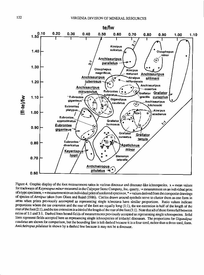
r22 VIRGINIA DIVISION OF MINERAL RESOURCES
telfw0.10 0.20 0.30 0.40 0.50 0.60 0.70 1 .101.50
1.10
1.00
0.90
0.70
0.60
Figure 4. Graphic display of the foot measurement ratios in various dinosaur and dinosaur-like ichnospecies. x = mean valuesfor trackways of Kayentapus rzinor measured in the culpeper Stone company, Inc. quarry, .
= measurement on an individual printofa type specimen, + = measurementonan individualprintof areferred specimen, *
j values derivedfrom thecomp,ositedrawings
of species of Ateipus taken from Olsen and Baird (1936). Circles drawn around symbols serve to cluster them as one form inareas when prints previously accewpted as representing single ichnotaxa have similar proportions. Ratio values indicateproportions where the toe extension and the rear of the foot arc equally long (1:1), ttre toe extension is half of the length of therearofthefmt(2:1),andthetoeextensionisathirdofthelengthoftherearofthefoot(3:1). Notethatalloftheseformsfattbenueenratios of I : 1 and 3: 1. Dashed lines bound fields of measurements previously accepted as representing single ichnospecies. Solidlines represent fields accepted here as representing single ichnospecies of nidactyl dinosaurs. I'ne proponions foi Gigandipuscaudatus arc shown for comparison, but the bounding line is left dashed because it is a four-toed, rather than a three-toed, form.Anticheiropus pilulatus is shown by a dashed line because it may not be a dinosaur.
3\o
#I
h
0.80 0.90 1.00
Atreipussulcatus
Anchisauripus,minot.Jr(:t
I
Atreipusmetzneri
Otouphepus
(rr', parallelus
Otouphepus.+ +
Anchisauripussillimani
gracilis cursoriusAnchisauripus
Atreipusacadianus
AnchisauripustuberosusI
Anchisauripus
approximatus
"Eubrontesgiganteus'
EubronteSplatypus
I
Eubrontesdivaricatus
Eubrontesgiganteus
I cuneatus
AnticheiropuS zr-.plg!et"" .:t':l
fXY\€yi j,
-g)
7,
b,''lII
Ye
?u\$,3{f ,,/
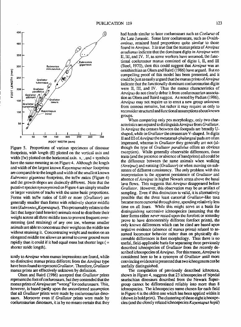
PUBLICATION 119 r23
E
i zsoF(9zu.l
i zoo
oL
0 50 100 150 200 250 3
FOOT WIDTH (mm)
Figure 5. Proportions of various specimens of dinosaurfootprints, with length (fl) plotted on the vertical axis andwidth (fw) plotted on the horizontal axis. x,., and + symbolshave the same meaning as on Figure 4. Although the lengthand width of the largest kn own Kayentapzs ninor footprintsare comparable to the length and width of the smallest knownEubrontes giganteus footprints, the tefw ratios (Figue 4)and the growth slopes are distinctly different. Note that theputative species synonymized on Figure 4 are simply smalleror larger versions of tracks wittr the same basic proportions.Forms with tefw ratios of 0.60 or more (Grallator) wegenerally smaller than forms with relatively shorter middletoes (Eubrontes,.Kayentapzs). This presumably relates to thefact ttrat larger (and heavier) animals need to distribute theirweight across all three middle toes to prevent frequent over-stressing (and sraining) of any one toe, whereas smalleranimals are able to concentrate their weight on ttre middle toewithout sEaining it. Concenrating weight and motion on anelongated middle toe allows an animal to cover ground morerapidly than it could if it had equal mass but shorter legs ( =shorter stride length).
tenlly toAtrelpas when manus impressions are found, whileno distinctive manus prints different from the Atreipus typhavebeen found to represent Grallator. Thereforc,Grallatormanus prints are effectively unknown by definition.
Olsen and Baird (1986) accepted that Grallator prinsrepresent the feetof coelurosaurs, but they contended that themanus prints of Atreipus arc"wrong" for coelurosaurs. This,however, is based partly upon the unconfirmed assumptionthat aU Grallator gints were made by coelurosaurian dino-saurs. Moreover even if Grallator prints were made bycoelurosaurian dinosaun, it is by no means certain that they
had hands similar to later coelurosaurs such as Coelurus ofthe Late Jurassic. Some later coelurosaurs, such as Ornith-omiruts, retained hand proportions quite similar to thosefound in Atrelpzs. It is true that the manus prints of Atreipusacadianus indicate that the dominant digitsinAtreipil.T wereII, III, and IV. If, as some workers have assumed, the func-tional coelurosaur manus consisted of digits I, II, and trI(Steel, 1970), then this could suggest that Atreipur was an
ornithischian as Olsen and Baird (1986) have argued. But nocompelling proof of this model has been presented, and itcould be just as easily argued that the manus prints ofAtrelpusindicate that ttre functionally dominant coelurosaurian digitswere II, III, and IV. Thus the manus characteristics ofAtreipus do not clearly debar it from coelurosaurian associa-tion as Olsen and Baird suggest. As noted by Padian (1986),Atreipus may not require us !o erect a new group unknownfrom osseous remains, but rather it may require us only toreconsider structural and functional assumptions aboutknowngroups.
When comparing only pes morphology, only two char-acteristics are reputed to distinguishAtrelp us from Grallator.ln Atreipus the creases between the footpads are broadly U-shaped, while inGrallatorthecreases are V-shaped. In digitsII and III ofA treipus themetatarsal-phalangeal pads are oftenimpressed, whereas in Grallator they generally are not (al-though tlre type of Grallator parallelus offers an obviousexception). While generally observable differences, thesetraits (and ttre presence or absence ofhandprins) all could bethe difference between the same animals when walking(Atreipus)and running (Grallator) or when moving on sub-strates of different consistency. The only problem wi*t thisinterpretation is the apparent persistence of Grallator andabsence of Atreipus in higher Newark strata above the basallava flows. This suggests tl:n;t Atreipus disappeared beforeGrallator. However, this observation may be an artifact ofsampling. Even if this distinction is valid, it is alternativelypossible that the three least cursorial Grallator-hke taxabecame more cursorial through time, spending relatively less
time on all fours. While this might serve as a basis fordistinguishing successive ichnospecies (assuming that thelater forms either never rested upon the forefeet or somedayprove to have demonsrably different forefoot prints), theonly known differences which can be cited are based uponnegative evidence (absence of manus prints) related to as-
sumed locomotor behavior rather than on physically dis-cernable differences in foot morphology. Thus there is nouseful, field-applicable basis for separating three previouslydescribed ichnospecies of. Grallator from the recently de-scribed ichnospecies of Atrelpzs. For this rcason, Atreipus isconsidered here to be a synonym of Grallator until moreconvincing evidence is presented that two ichnogenera can beusefully distinguished.
The compilation of previously described ichnotrxa,shown in Figure 4, suggests lhatz3 ichnospecies of bipedalsaurischian dinosaurs described from the Newark Super-group cannot be differentiated reliably into more than 8ichnospecies. The ichnospecies name chosen for each fieldin Figure 4 is the oldest one which has been applied within it(shown in bold print). The clustering of these eight ichnospe-cies (and the closely related ichnospecies Kayentapus lwpil
Kayentapus
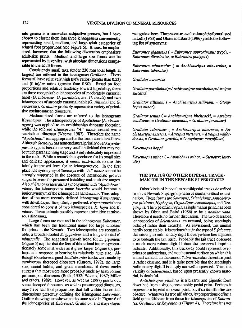
ta YIRGINIA DIVISION OF MINERAL RESOURCES
into genera is a somewhat subjective process, but I havechosen to cluster them ino three ichnogenera convenientlyrepresenting small, medium, and large adult categories ofrelated foot proportions (see Figure 5). It must be empha-sized, however, that the following discussion emphasizesadult-size prints. Medium and large size forms can berepresented by juveniles, with absolute dimensions oompa-rable to the adult forms.
Consistently small taxa (under 230 mm toal length atlargesg are referred to the ichnogents Grallator. Theseforms all have relatively high telfiv ratios Greater than 0.53)and (fl-te)fw ratios (greater than 0.90). Based on footproportions and relative tendency toward bipedality, thereare tlree recognizable ichnospecies of moderately cursorialhabit (G. tuberosus, G. parallelus, and G. tenuis) and twoichnospecies of srongly cursorial habit (G. sillimani and G.cwsorius). Grallator probably represents a variety of primi-tive coelurosaurian dinosaurs.
Medium-sized forms are referred to the ichnogenusKayentapus. The ichnogenotyp of Apatichnus {A. circum-agens\ was applied to an ornithischian dinosaur footprint,while the referred ichnospecies "A." minor instead was asaurischian dinosaur (Weems, 1987). Therefore the name"Apatichnus" is inappropriate for the forms considered here.Alttrough Ste nonyr has nomenclatural pri oity over Kayenta-prs, its rype is based on a very small individual that may notbe much past hatchling stage and is only delicately impressedin the rock. While a remarkable specimen for is small sizeand delicate appearance, it seems inadvisable to use thisfaintly impressed form for an ichnogenotype. In 0re lrstplace, the synonymy of Stenonyx with %." minor cannotbestrongly supported in the absence of intermediate growthstages between thepresumed hatchling and adult sizeranges.Also, if Steno ny x laterali s is synonymou s with " Apatic hnus"mirar, the ichnospecies name lateralis would become ajunior synonym of ttre ichnospecies name minor. Thus, adop-tion of the more recently defined ichnogenus Kayentapus,with its valid specific epithet, is prefened. Kayentapusishereconsidered to consist of two ichnospecies, K. hopii and K.mircr. These animals possibly represent primitive carnivo-rous dinosaurs.
Large forms are retained in the ichnogenus Eubrontes,which has been the traditional name for laree dinosaurfootprints in the Newark. Two ichnospecies ie recogniz-able, a broader-fmted E. giganteus and a longer-footed E.minusculis. The suggested growth trend for E. giganteus(Frgure 5) implies that the feet of this animal became propor-tionately somewhat wider as it grew larger (Figure 6), per-haps as a response to bearing its relatively huge size. Al-though some have argued th atEubrontes ttacks were made bycarnivorous theropod dinosaurs (Ostrom, 1972), the largesize, social habits, and great abundance of these trackssuggest that most were more probably made by herbivorousprosauropod dinosaurs (Bock, 1952; Weems, 1987; Millerand others, 1989). However, as Weems (1987) points out,some theropod dinosaurs, as well as prosauropod dinosaurs,may have had foot proportions that fall within $re criticaldimensions presently defining the ichnogenls Eubrontes.Outline drawings are shown to the same scale in Figure 6 ofthe ichnospecies of Eubrontes, Grallator, and Kayentapus
recognized here. The presentre-evaluation of the fcms listedin Lull (1953) andOlsen and Baird (1986) yields the follow-ing list of synonyms:
Eubrontes giganteus (= Eubrontes approimatw (type), =Eubronte s divaricatw, = Eubrontes plarypus)
Eubrontes minusculus ( = Anchisauripus minusculus, =Eubrontes uberatus)
Grallator cursorius
Grallator parallelus (= lnshisauripus parallelus,= l17sirussulcatw)
Grallator sillinani ( = Anchisauripus sillitnani, = Q16uO-hepus minor)
Grallator tenuis (= Anchisauripus hitchcocki, = Atreipusacadianus, = Grallator cuneatus, = Grallator fornnsus)
Grallator tuberosus ( = Anchisauipus tuberosils, = lJ1-c hisauripus exsertus, = l17sipus mz tzneri, = Atreipus milfur-de nsis, = Grallator gracilis, = O touphepus nagnificus)
Kayentapus hoppi
Kayentapus minor (= Apatichnus minor,= Stenonyx later-alis)
THE STATUS OF OTHER BIPEDAL TRACK.MAKERS IN THE NEWARK SUPERGROUP
Other kinds of bipedal to semibipedal racks describedfrom the Newark Supergroup deserve similar critical exami-nation. These forms are Sawopus, Selenichnus, Anticheiro-pus pilulatus, Hyphepw , Gigandipus , Anomoepus, and Gre-garipus. The typeof Sawopus,asingle manusprint, hasbeenshown by Olsen and Baird (1986) to be a nomina vana.Therefore it needs no further discussion. The two describedichnospecies of Selenichnu.r are unusual, being seeminglybidactyl rather than ridactyl. As envisioned, this animalhardly seem stable. It is curious that, in the typeof S.falcatus,the missing to rudimentary digit II everywhere lies adjacentto or beneath the tail trace. Probably the rail trace obscureda much more robust digit II than the preserved imprintsindicate. Additionally, this uackway could represent over-prints or underprints, and not the actual surface on which thisanimal walked. In the case of S. breviuscalrs the entire printis rather obscure, and it is quite possible that the seeminglyrudimentary digit II is simply not well impressed. Thus, thevalidity of Selenichnus, based upon presently lnown mate-rial, is doubtful.
Anticheiropus pilulatus is a bizarre and gigantic formdescribed from a single, presumably pedal print. Perhaps itrepresents a bipedal dinosaurprint, but ifso its affinities areobscure. Whatever its true affinities, its proportions define afield quite different from tlose for ichnospecies of Eubron-tes, Grallator, or Kayentapus (Figure 4). Therefore it is not
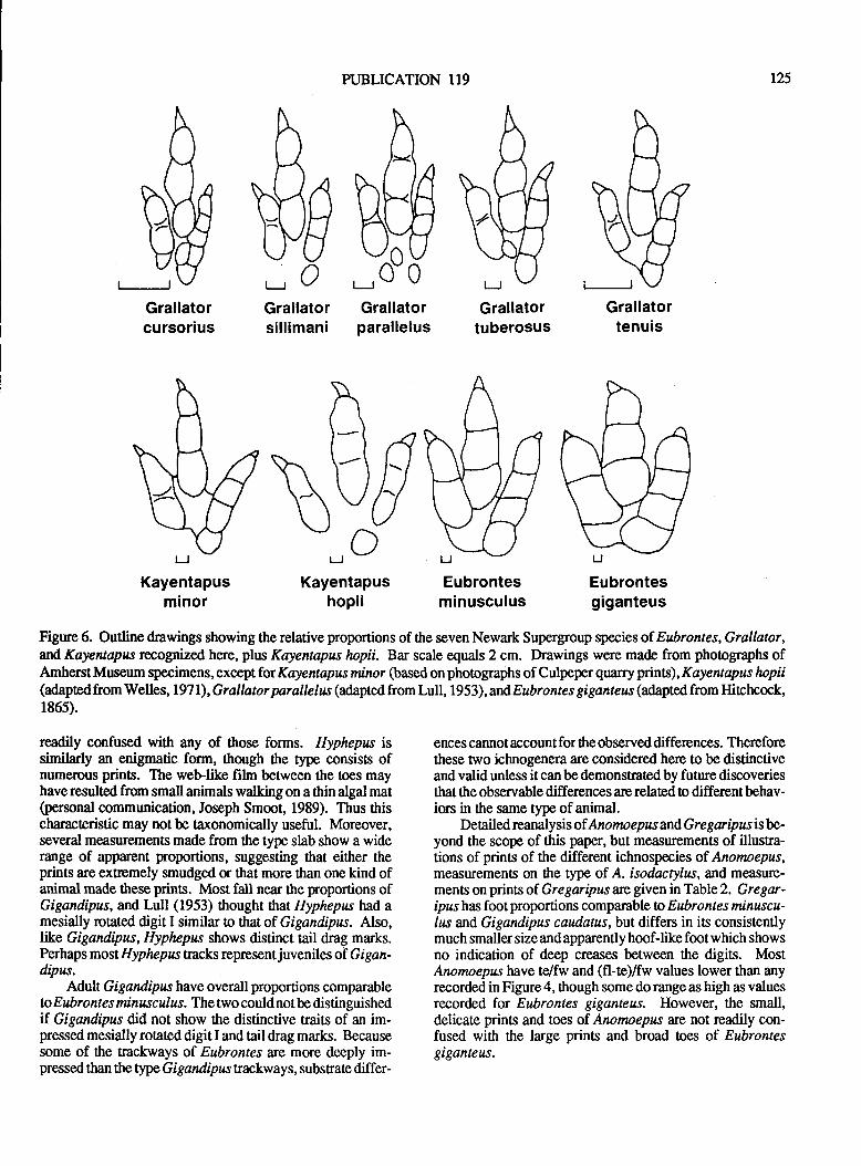
Grallatorcursorius
PUBLICATION II9
Grallatorparallelus
Grallatortuberosus
125
Kayentapusminor
Grallatortenuis
Eubrontesgiganteus
t-r OGrallatorsillimani
P\
\u []r._,dKayentapus
hopii
Figtne 6. Outline drawings showing the relative proportions of the seven Newark Supergroup species of Enbrontes, Grallator,and Kayentapus recognized here, plus Kayentapus hopii. Bar scale equals 2 cm. Drawings were made from phoographs ofAmherst Museum specimens, except for Kayentapus minor (based on phoographs of Culpeper quarry prints), Kcye ntapus hopii(adaptedfromWelles, l97l),Grallator parallelw (adapted from Lull, 1953),and Eubrontes giganteus (adaptdfrom Hitchcock,1865).
readily confused with any of those forms. Hyphepw issimilarly an enigmatic form, though the type consists ofnumerous prints. The web-like film betrveen the toes mayhave resulted from small animals walking on a thin algal mat(personal communication, Joseph Smoot, 1989). Thus thischaracteristic may not be taxonomically useful. Moreover,several measurements made from the type slab show a widerange of apparent proportions, suggesting that either theprints are extremely smudged or that more than one kind ofanimal made these prints. Most fall near the proportions ofGigandipus, and Lull (1953) thought that Hyphepw tuid amesially rotated digit I similar o that of Gigandipus. Also,hke Gigandipus, Hyphepus shows distinct tail drag marks.Perhaps most Hyphepwtacks representjuveniles of Gigaz-dipus.
Adult Gigandipzs have overall proportions comparableto Eubronte s minusculus. The two could not be distinguishedif Gigandipus did not show the distinctive traits of an im-pressed mesially rotated digit I and tail drag marks. Becausesome of the trackways of EubronteJ are more deeply im-pressed than the typeGigandiplr trackways, substrate differ-
Eubrontesminusculus
ences cannot account for the observed differcnces. Thereforethese two ichnogenera are considered here 0o be distinctiveand valid unless it can be demonstrated by funre discoveriesthat the observable differences are related o different behav-iors in the same type of animal.
Deailed reanaly sis of Ano rno e pus and G r e gar ip us is be-yond the scope of this paper, but measurements of illusra-tions of prints of the different ichnospocies of Anomoepus,measurements on the type of A. isodacrylw, and measure-ments on prints of. Gregaripns are given in Table 2. Gregar-ipzs has foot proportions comparable to Eubrontes minuscu-lres and Gigandipus caudatus, but diffen in its consistentlymuch smaller size and apparently hoof-like foot which showsno indication of deep creases between the digis. MostAnomoepus have tefw and (fl-te)fw values lower than anyrecorded in Figure 4, though some do range as high as valuesrecorded for Eubrontes giganteus. However, the small,delicate prints and toes of Anomoepus arc not readily con-fused with the large prins and broad toes of Eubrontesgiganteus.
126 VIRGIMA DIVISION OF MINERAL RESOURCES
CURRENT TAXONOMIC STATUS OF THECULPEPER STONE COMPANY, INC.
QUARRY FOOTPRINTS
In view of this taxonomic revision, tlte current taxonomyof the new and previously described footprints from theCulpeper quarry are summarized here. Agrestipus hottoni,Gregaripus bairdi,and,Eubrontes sp., described by Weems(1987) from the upper track bearing surface, remain un-changed. The footprints described as "Apatichnus" minor,on the basis of the preceding taxonomic analysis, are nowreferable to the new combinatton Kayentap,ns mjnor withoutfurther change (Figure 7). Measurementof the middle toe ex-tension to ftack width ratio for Grallator? yields a value ( I . I 5in USNM 358657) which is larger rhan rhar recorded fromany well preserved material. This is probably because the tipof the toedraggedas the animal moved forward in deep mud,artificially elongating the apparenl length of the toe print inUSNM 358657. But besides the telfw rario, the speedestimates for this animal and the size of these prints alsosuggest that these tracks are referable to a long-toed ichno-species. Their general proportions and molphology do notsuggest anything other ttran Grallator ,so these prinB here areassigned to Grallator cf. G. sillinwni.
The prints previously referre dtn Anchisauripus paralle-/ru probably do not belong to tlat form. On reanalysis, thespecimen on which that identification was based seems toinclude an impression of the metatarsal region, which gavethe print an artificially long appearance. The best estimatesfor'the tefw ratio (0.57 to 0.62) and fl-te)fw rario (0.99 ro1.14) range between and slighrly into the fields of borhEubrontes minusculus and Grallator tuberosus. However,considering its poor preservation, its size (smaller than anyknoJvn Eubrontes),and geologic age (older than any previ-ously reported Eubrontes minusculus), this trackway can belinked circumstantially to Grallator tuberosus. Therefore itis here termed Grallator cf. G. tuberosus.
On the lower track bearing surface, most footprints arcreferableta Kayentapus minor. A few small isolated ridactylprins have telfw proportions (0.84) typical of Grallatorsillinnni udthus are referred o that taxon. Elongate scratchmarks which curve at the end probably represent claw marksleft on the shallow lake bottom by swimming parasuchians(represented osteologically by an isolated tooth). Althoughtoo poorly preserved to be certain, tlese are tentatively refer-able to the ichnotaxon Apatopus lineatus. A fourth (quadrup-sdal) taxon, apparently a short-tailed banel-bodied aetosaursimilar o Typo thorax, apyars to represent a new ichnotaxonas yet unnamed.
ACKNOWLEDGEMENTS
I would like to thank the numerous individuals who atone time or another have aided me in exposing trackways,recording dat4 and mapping the footprints on the lowerCulpeper quarry trackway bedding plane. Jonathon Bach-man, Virginia Gonzalez, Robert Hodge, Frank Tseng, Elean-ora Robbins, and Su-Chiu Weems deserve special mentionfor the exceptional amountsof timeandeffort they provided.
The ownen and operators of the Culpeper Stone Company,Inc. quarry, especially Gordon Willis, Fred Harris, and RobertClore (who discovered the tracks on this surface), wereexceptionally helpful and deserve commendation for ttreirgenerous and public-spirited effors on behalf of this study.Linda Thomas, Walter Coombs, and Margery Coombs pro-videdvaluable insights, assistance, andhospirality during myvisit to the marvelous and invaluable Pratt Museum collec-tions of dinosaur footprints at Amherst College. Finally, Iwish to thank Ronald Litwin and Glen Kuban for theirthorough and insightful reviews of this paper.
REFERENCES CITED
Baird, Donald, 1957, Triassic reptile footprint faunules fromMilford, New Jersey: Museum of Comparative Zoology ofHarvard College, Bulletin, vol. 117, no. 5, p. 449-520.
Bock, Wilhelm,l952,Triassic reptilian tracks and trends ofloconrotive evolution: Journal of Paleontology, vol. 26,no.3,p.395-433.
Carrozi, A.V., 1964, Complex ooids from Triassic lakedeposit, Virginia: American Journal of Science, vol.262,no.2,p.231-241.
Gillette, M.G., and Lockley, D.D., 1 989, Dinosaur tracks andtraces: an overview: in Gillette, M.G., and Lockley, D.D.(eds.), Dinosaur Tracks and Traces: Cambridge UniversiryPress, New York, p. 3-10.
Hitchcock, Edward, 1858, Ichnology of New England. Areport on the sandstone of the Connecticut valley, especiallyits fossil footmarks: Boston, William White, p.l-220.
Hitchcock, Edward, 1865, Supplement to the ichnology ofNew England: Wright and Potter, Boston, p. 1-96.
Lull, R.S., 1953, Triassic life of the Connecticut valley:Connecticut State Geological and Natural History Survey,Bulletin 24,p.l-285.
Miller, W.8., Britt, B.B., and S tadtman, K.L., I 979, Tridactyltrackways from the Moenave Formation of southwesternUmh: rn Gillette, M.G., and Lockley, D.D., (eds.), DinosaurTracks and Traces: Cambridge University Press, New York,p.N9-215.
Olsen, P.E., and Baird, Donald, 1986, The ichnogenusArreipresand is significance for Triassic biosratigraphy: iz KevinPadian (ed.), The beginning of the age of dinosaurs: Faunalchange across the Triassic-Jurassic boundary: CambridgeUniversity Press, Cambridge, MA, p. 61-87.
Ostrom, J.H., 1972, Were some dinosaurs gregarious?: Pale-ogeography, Paleoclimatology, Paleoecology, vol. ll, p.287-30t.
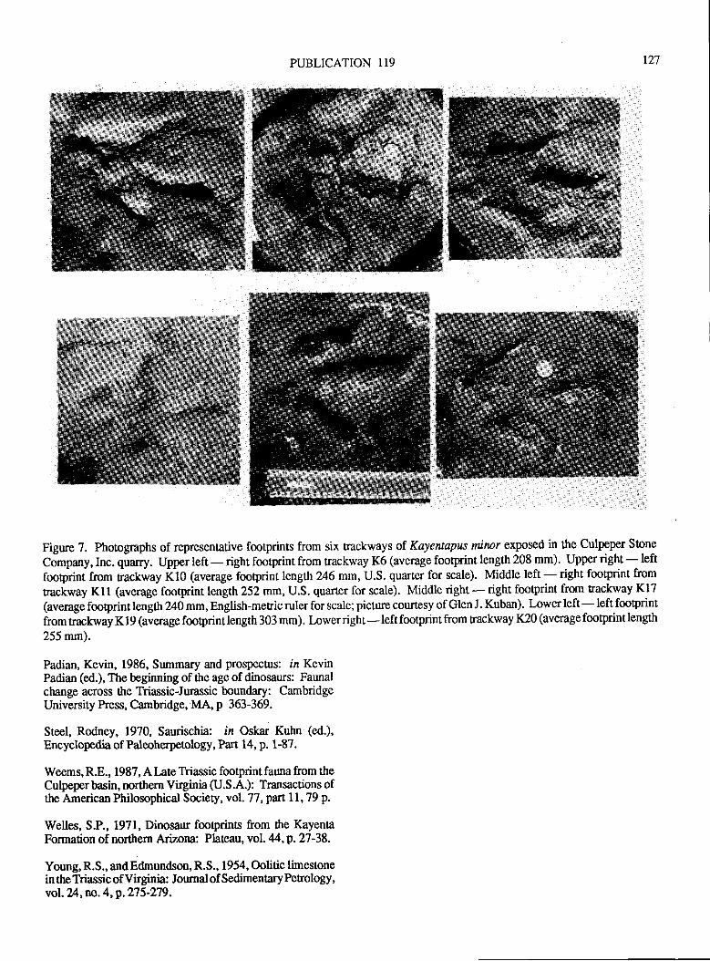
PUBLICATION 119
Figure ?. photographs of representative fmtprints from six trackways of Kayentapus mirnr exposed in the Culpeper Stone
Company, Inc. quarry. Upper tet - right footprint from trackway K6 (average footprint length 208 mm). Upper right - left
tooprint from rackway t<10 lauerage footprint length%6 mm, U.S. quarter for scale). Middle left - right footprint from
nackway Kll (average footprint length 252 mm, U.S. qua.rter for scale). Middle right * right footprint from trackway K17
(averagefooprintlength240mm,English-metricrulerforscale;picturecourtesyofGlenJ.Kuban). Lowerleft-leftfootprintfromrackwayKlg(averagefooprintlength303mm).I-owerright-leftfootprintfromtrackwayK20(averagefootprintlength255 mm).
Padian, Kevin, 1986, Summary and prospectus: in KevinPadian (ed.), The beginning of the age of dinosaurs: Faunalchange across the Triassic-Jurassic boundary: CambridgeUniversity Press, Cambridge, MA, p 363-369.
Steel, Rodney, 1970, Saurischia: in Oskar Kuhn (ed.),
Encyclopedia ofPaleoherpetology, Part 14, p. 1-87.
Weems, R.E., 1987, A Late Triassic footprint fauna from theCulpeper basin, northern Virginia (U.S.A.): Transactions ofthe American Philosophical Society, vol. 77, part ll, 79 p.
Welles, S.P., 1971, Dinosaur fooprins from the KayenaFormation of northern Arizona: Plateau, vol. 44, p. 27-38.
Young, R.S., and Edmundson, R.S., 1954, Oolitic limestonein theTriassic of Virginia: Journal of SedimentaryPerology,vol. ?t4,no. 4, p. n 5-279.
r27
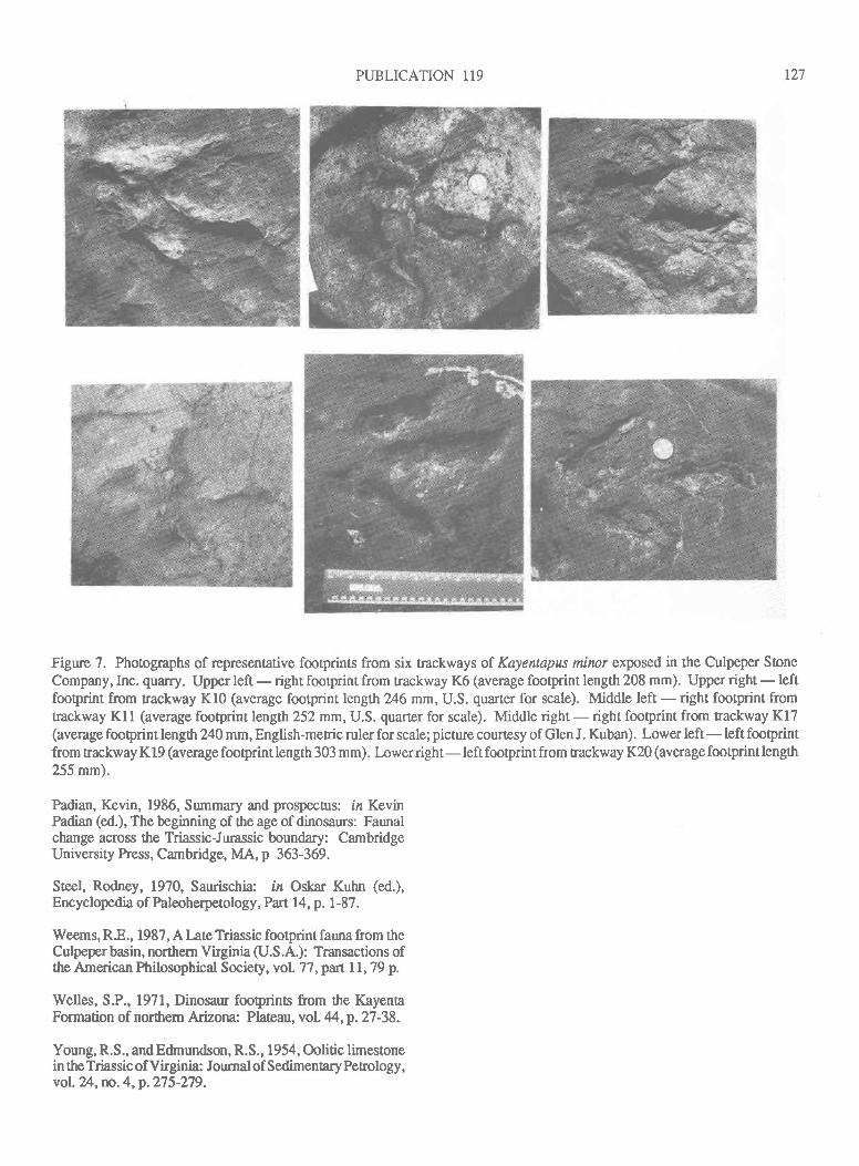
PUBLICATION 119
Figure 7. Photographs of representative fmtprints from six trackways of Kayentapus minor exposed in the Culpeper SoneCompany, Inc. quarry. Upper left - right footprint from trackway K6 (average footprint length 208 mm). Upper right - leftfooprint from trackway KlO (average footprint lengt\246 mm, U.S. quarter for scale). Middle left - right footprint fromtrackway Kll (average footprint length252 mm, U.S. quarter for scale). Middle right - right footprint from trackway Kl7(averagefooprintlengtlr240mm,English-metricrulerforscale;picturecourtesyofGlenJ.Kuban). Lowerleft-leftfootprintfromtrackwayKl9(averagefooprintlength303mm). Lowerright-leftfootprintfromtrackwayK20(averagefootprintlength255 mm).
Padian, Kevin, 1986, Summary and prospecurs: in KevinPadian (ed.), The beginning of the age of dinosaurs: Faunalchange across the Triassic-Jurassic boundary: CambridgeUniversity Press, Cambridge, MA, p 363-369.
Steel, Rodney, 1970, Saurischia: iz Oskar Kuhn (ed.),Encyclopedia ofPaleoherpetology, Part 14, p. l-87.
Weems, R.8., 1987, A late Triassic footprint fauna from theCulpeper basin, northem Virginia (U.S.A.): Transactions ofthe American Philosophical Society, vol. 77 , part I l, 79 p.
Welles, S.P., 1971, Dinosaur fooprins from the KayentaFormation of northem Arizona: Plateau, vo1.44,p.27-38.
Young, R.S., andEdmundson, R.S., 1954, Oolitic limestonein the Triassic of Virginia: Journal of SedimentaryPetrology,vol.2A, no. 4, p. 275-279.
r27

t28 VIRGINIA DIVISION OF MINERAL RESOT'RCES
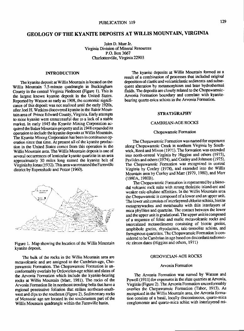
PUBLICATION I19
GEOLOGY OF THE KYANITE DEPOSITS AT WILL$ MOUNTAIN, VIRGINIA
John D. Man Jr.Virginia Division of Mineral Resources
P.O. Box 3667Charlottesvill e, Y k gnria 22903
r29
INTRODUCTION
The kyanite deposit atWillis Mountain is located on theWillis Mountain 7.5-minute quadrangle in BuckinghamCounty in the central Virginia Piedmont (Figue l). This is
the largest known kyanite deposit in the United States.
Reported by Watson as early as 1908, the economic signifi-cance of this deposit was not realized until the early 1920s,
afterJoel H. Watkins discoveredkyanitein the Baker Moun-tain area of Prince Edward County, Virginia. Early attemptsto mine kyanite werg unsuccessful due to a lack of a stablemarket.In early 1945 the Kyanite Mining Co'rporation ac-quired the Baker Mountain property and in 1948 expanded itsoperation to include thekyanite deposits atWillis Mountain.The Kyanite Mining Corporation has been in continuous operation since that time. At present all of the kyanite produc-tion in the United States comes from this operation in theWillisMountain area. TheWillis Mountain depositis one ofseveral occurrences of lenticular kyanite quartzite in an area
approximately 30 miles long named 0re kyanite belt ofVirginiaby Jonas (1932). This areawasrenamedtheFarmvilledisrict by Espenshade and Potter (1%0).
Figue 1. Map showing ttre location of the Willis Mountainkyanite deposit.
The bulk of the rocks in the Willis Mountain area are
metavolcanic and are assigned to the Cambrian-age, Cho-pawamsic Formation. The Chopawamsic Formation is un-
conformably overlain by Ordovician-age schist and slates ofthe Arvonia Formation which include the kyanite-bearingrocks at Willis Mountain (Marr, 1981). The rocks of theArvonia Formation lie in northeast trending belts that have aregional penetrative foliation that stikes northeast-south-west and dips to the southeast @gure 2). Sedimentary roclsof Mesozoic age are located in the southeastern part of theWillis Mountain quadrangle within the Farmville basin.
The kyanite deposits at Willis Mountain formed as a
result of a combination of processes that included originaldeposition of clastic and volcaniclastic sediments and subse-
quent alteration by metamorphism and later hydrothermal
fluids. The deposits are closely related o the Chopawamsic-Arvonia Formation boundary and conelate with kyanite-
bearing quartz-mica schists in the ArvoniaFumation.
STRATIGRAPHY
CAMBRIAN.AGE ROCKS
Chopawamsic Formation
The Chopawamsic Formation was named fm exposures
along Chopawamsic Creek in northern Virginia by Soutlt;wick, Reed and Mixon (1971). The formation was extended
into north-central Virginia by Higgins and others (1973),
Pavlides and others (1974), and Conley and Johnson (1975)'
The Chopawamsic Formation was recognized in cenFal
Virginia by Conley (1978), and extended into the WillisMountain area by Conley and Marr (1979,1980)' and Man(1980A,19808).
The Chopawamsic Formation is representedby abimo-dal volcanic rock suite with strong tholeiitic island-arc and
weaker calc-alkaline affinities. In the Willis Mountain area
the Chopawamsic is composed of a lower and an upper unilThe lower unit consists of interlayered chlorite schists, biotitemetagraywackes and metabasalts with thin interlayers ofmica phyllites and quartzite. The contact between the lowerand the upper unit is gradational. The upper unitis composed
of a sequence of felsic and mafic metavolcanic rocks and
intercalated metasediments consisting of biotite gneiss,
amphibole gneiss, rhyodacites, talc-Eemolite schists, and
femrginous quartzites. The Chopawamsic Formation is con-
sidered to be Cambrian in age based on discordant radiomet-
ric zircon dates (Higgins and othen, 1971)
ORDOVICIAN-AGE ROCKS
Arvonia Formation
The Arvonia Formation was named by Watson and
Powell (1911) for exposures in ttre slate quarries at Arvonia,Virginia (Figure 2). The AwoniaFormation unconformably
oveilies the Chopawamsic Formation (Tabor, 1913). As
recosnized in the Willis Mountain area, the Arvonia forma-
tionionsists of a basdl, locally discontinuous, quartz'mica
conglomerate and quartz-mica schist with interlayered mi-
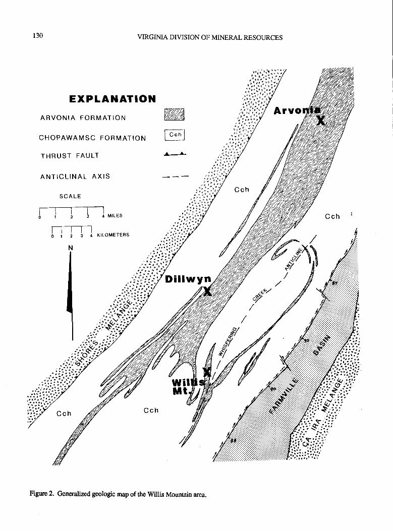
130 VIRGIMA DIVISION OF MINERAL RESOURCES
Arvo
Cch '
Figure 2. Generalized geologic map of the Willis Mountain area.
PUBLICATION 119 131
caceous quartzite. This interlayered interval is overlain by amoderately persistent, banded quartzite which is in turnoverlain by a thick interval of porphyroblastic, garnet-mica-graphite schist. The Arvonia Formation also includes thekyanite-schists and conglomerates located on Willis Moun-tain. These kyanite-bearing quartz-mica schists and con-glomerates were correlated with the basal units of the ArvoniaFormation by Conley and Marr (1980). At Willis Mountainkyanite constitutes as much as3l%o of the rock. It occurs as
stringers andlenses within schistbeds atWillis Mountain andat Arvonia it occurs as disseminated blades in the quartz-micaconglomerate of the basal Arvonia Formation @vans andMar, 1988). Sillimanite is also found in the conglomerate atboth Willis Mountain and at Arvonia as fibrous prismaticcrystals.
At Willis Mountain and at Woods Mountain the kyaniteschist exhibits primary sedimentary sEuctures. These in-clude: repeated pairs of wedge-shaped quartzite and metape-lite interlayers, conglomerates, fining-upward sequences,channel-fillings and both large-scale and small-scale cross-beds (Conley and Man, 1980).
The rocks of the ArvoniaFormation are considered o beMiddle to Late Ordovician in age based on fossils identifiedat Arvonia, Virginia. Fossils that have been identified in-clude: brachiopods, bryozoans, crinoids, pelecypods andtrilobites (Darton, 1892; Dale, 1906; Watson and Powell,191 1; Smith, Milici and Greenburg, 1964; Brown, 1969; andTillman, 1970). The slales at Arvonia have been dated at 300m.y. using the whole-rockK-Ar method (Harper, andotlers,1973). This date does not correspond to any known orogenicevent affecting the rocks of the Virginia Piedmont andprobably represents a time of cooling following a metamor-phic event when the rocks formed a closed K-Ar system(Iladley, 1964).
JURASSIC-AGE ROCKS
Diabase Dikes
Diabase dikes of Jurassic-age intude all crystallinerocks of thearea,as well as, theTriassic-agesediments in theFarmville Basin. The diabase is dark-gray to black, fine- tomedium-grained and has an ophitic textue. One of thesedikes inrudes the kyanite schist at Willis Mountain near thesouthern end of the quarry.
STRUCTURAL CONSIDERATIONS
The roc*s in the Willis Mountain area record four dis-tinctperiods of folding, one of which is foundonly wittrin theChopawamsic Formation which preceded deposition of therocks of the Arvonia Formation. Major structural featurespresent include the Whispering Creek anticline, synclinalinfolds of Arvonia Formation rocks, several small-scaleshearzones associated with tightly folded rocks. The Farmvillebasin was formed by normal faulting following the compres-sional event that produced the folds in both the Chopawamsicand Arvonia Formations. See Man ( I 980A) and ( I 9808) for
more complete structural discussion.
FOLDS
Isoclinal, intrafolial, rootless, Fl fold hinges can be
observed in outcrop on the limbs of largerF2 folds. TheseFlfolds were only observed within ttre rocks of the Cho-pawamsic Formation. This same relationship was described
Letween the folded rocks of the Chopawamsic and Quanticoformations in northern Virginia by Pavlides (1973).
F2 folds include tight, isoclinal synclines and broader,
more open anticlines. These folds generally strike to the
northeast and are overturned to ttre northwest. 52 penetrative
foliation is seen in all Paleozoic rocks of the area and is best
developed in the rocks of the Arvonia Formation.F3 folds are recognizeable at map scale where the pene-
trative 52 foliation is wapped around F3 structures.F4 Folds are also recognizeable at map scale where F3
folds have been warped by northeast-trending F4 structues.
FAULT
A fault zone bounds the Farmville basin on its western
side. This fault is a high-angle normal fault that strikes
northeast and dips to the southeast. The fault consists offine-grained siliceous mylonite and extensively brecciated and
silica-cemented cataclastic rock.
STMARZONES
There are several nalTow, discontinuous shear zones
developed in the rocks ofthe area. These zones are developed
along the flanks of major folds and are believed to begenetically related to the folding mechanism. These shear
zones are particularly well developed along the flanks oftheArvonia Formation.
MELANGEZONES
Thelowerunitof ttre ChopawamsicFormationis bounded
along its western side by a melange zone consisting of quartz-
feldspar metadiamictite that contains exotic blocks of maficand ulramafic material. This melange occulrence is alongstrike to the northeast with the Shores Complex as described
by Brown, (1986). This melange might also correlate withmelange described in northern Virginiaby Drake (1986) and
Pavlides (1989). Subsurface reflection profiling across the
cenral Virginia Piedmont indicates that the Shores Complexis bounded on the south-east side by an east-dipping low-angle thrust fault (Glover and Costain, 1982; Wehr and
Glover, 1985).A second previously unrcported melange unit bounds
the Farmville basin along its eastem boundary. This melange
is informally named the Ca Ira melange for exposures in Rock
Creek and other northwest trending drainages along the east
side of the Willis River at Ca Ira, Virginia. This melange unit
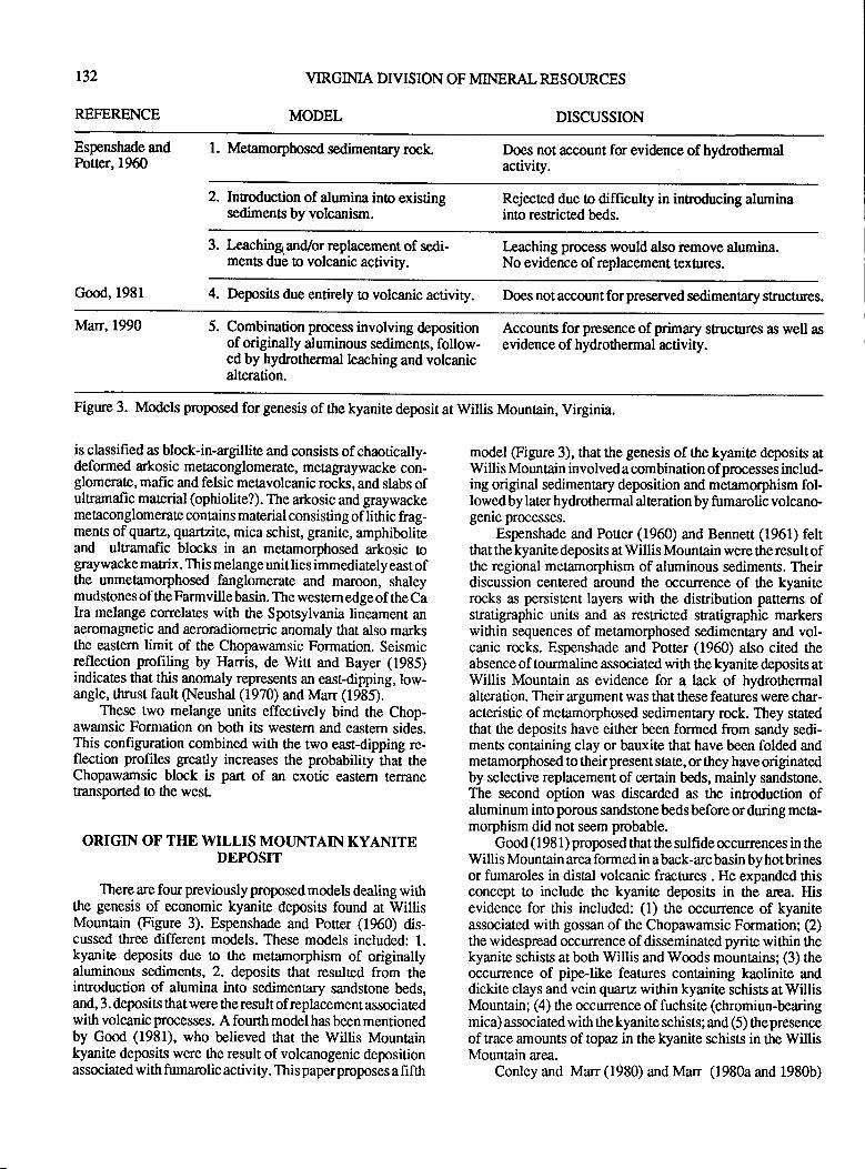
r32
REFERENCE
VIRGINIA DIVISION OF MINERAL RESOURCES
MODEL DISCUSSION
Espenshade andPotter,1960
l. Mehmorphosed sedimentary rock. Does not account for evidence ofhydrothermalactivity.
2. Inroduction of alumina ino existingsediments by volcanism.
Rejected due to difficulty in inroducing aluminainto resnicrcd beds.
3. Leachingl and/or replacement of sedi-ments due to volcanic activity.
Ieaching process would also remove alumina.No evidence of replacement tex$res.
Good, l98l 4. Deposits due entirely to volcanic activity. Does not account for preserved sedimenary structures.
Man,1990 5. Combination process involving depositionof originally aluminous sediments, follow-ed by hydrothermal leaching and volcanicalteration.
Accoun8 for presence of primary struchrres as well asevidence of hydrothermal activity.
Figure 3. Models proposed for genesis of the kyanite deposit at Willis Mountain, Virginia.
is classified as block-in-argillite and consists of chaotically-deformed arkosic metaconglomerate, metagraywacke con-glomerate, mafic and felsic metavolcanic rocks, and slabs ofulramafic mat€rial (ophiolite?). The arkosic and graywackemetaconglomerate contains material consisting of lithic frag-ments of quartz, quafiite, mica schist" granite, amphiboliteand ultramafic blocks in an metamorphosed arkosic tograywacke matrix. This melange unit lies immediately east oftle unmetamorphosed fanglomerate and maroon, shaleymudstones of theFarmvillebasin. The westernedgeof the Caka melange correlates with the Spotsylvania lineament anaeromagnetic and aeroradiometric anomaly that also marksthe eastern limit of the Chopawamsic Formation. Seismicreflection profiling by }Iarris, de Witt and Bayer (1935)indicates that this anomaly represents an east-dipping,low-angle, thrust fault (Neushal (1970) and Man (1935).
These two melange units effectively bind the Chop-awamsic Formation on both its western and eastern sides.This configuration combined with the two east-dipping re-flection profiles greatly increases the probability that theChopawamsic block is part of an exotic eastern teranetransported t0 the wesl
ORIGIN OF THE WILLIS MOT.JNTAIN KYANITEDEPOSIT
There are four previously proposed models dealing wittrthe genesis of economic kyanir deposits found at WillisMountain (Figure 3). Espenshade and Poner (1960) dis-cussed three different models. These models included: 1.kyanite deposits due to the metamorphism of originallyaluminous sediments, 2. deposits that resulted from theintroduction of alumina into sedimentary sandstone beds,and, 3. deposits that were the result of replacement associatedwith volcanic processes. A fourth model has been mentionedby Good (1981), who believed that the Willis Mountainkyanite deposits were the result of volcanogenic depositionassociated with fumarolic activity. This paperproposes a fi fth
model @gure 3), that the genesis of ttre kyanite deposis atWillis Mountain involved a combination of processes includ-ing original sedimentary deposition and metamorphism fol-lowed by later hydrothermal alteration by fumarolic volcano-genic processes.
Espenshade and Potter (1960) and Bennert (1961) feltthat the kyanite deposis at Willis Mountain were the result ofthe regional metamorphism of aluminous sediments. Theirdiscussion centered around the occurrence of the kyaniterocks as persistent layers with the distribution panerns ofstratigraphic units and as restricted sratigraphic markerswithin sequences of metamorphosed sedimentary and vol-canic rocks. Espenshade and Potter (1960) also cited theabsence of tourmaline associated with the kyanite deposits atWillis Mountain as evidence for a lack of hydrothermalalteration. Their argument was that these features were char-acteristic of metamorphosed sedimenrary rock. They statedthat the deposits have either been formed from sandy sedi-ments containing clay or bauxite that have been folded andmetamorphosed to their present state, or they have originatedby selective replacement of certain beds, mainly sandstone.The second option was discarded as the inroduction ofaluminum into porous sandstonebedsbefore orduring meta-morphism did not seem probable.
Good (1981) proposed that the sulfide occurrences in theWillis Mountain area formed in a back-arc basin by hot brinesor fumaroles in distal volcanic fractures . He expanded ttrisconcept to include the kyanite deposits in the area. Hisevidence for this included: (1) the occurence of kyaniteassociated wittr gossan of the Chopawamsic Formation; (2)the widespread occrurence of disseminated pyrite within thekyanite schists at both Willis and Woods mountains; (3) theoccurence of pipe-like features containing kaolinite anddickite clays and vein quartz within kyanite schists at WillisMountain; (a) the occurence of fuchsite (chromiun-bearingmica) associated wittr thekyaniteschists; and (5) ttrepresenceof trace amounts of topaz in the kyanite schists in the WillisMountain area.
Conley and Marr (1980) and Man (1980a and 1980b)
PUBLICATION 119 133
ctrrelat€d the kyanite schists at Willis Mountain with thequartz-mica schists in ttre basal portion of the Arvonia For-mation. This conelation was based on similar stratigraphicsequences and the presence of preserved pnmary sedimen-tary structure.s. The internal stratigraphy atWillis Mountainconsists of a lower kyanite-quartz-mica schist and an upperunit ofkyanite-quartz schist ovedain by a resricted occur-rence of graphitic meapelite. This sratigraphy at WillisMountain matches the internal sratigraphy of the ArvoniaFormation at its type locality.
The kyanite schistcontains preservedprimary structuresconsisting of wedge-shaped sedimentary packages composedof quartzite and quartzose kyanite couples. The basal beds ofmany of these packages contain conglomerates that grade
upward into quartzite and terminate at the top as a layer ofalmostpure quartzite. These features are interpreted as repre-senting originally deposited fining-upward sequences. Eachsequence was originally composed of a basal quartz gravel orcoarse quartz sand that fines upward into silt and clay. Eachpackage is truncatedby the nextoverlying package. There aresmall-scale cross-beds in some packages. Channel fill struc-tures truncate some of the cross-beds. All of these features areconsidered as evidence of original sedimentary deposition forthe kyanite-quartz schiss at Willis Mountain.
Barly Paleozoic metamorphism of the rocks in the WillisMountain area reached the upper amphibolite facies ofmedium- to high- gnde regional dynamothermal metamor-phism andimposedaregional foliation on all the rocks of thearea. At this time the clay portion of the sedimentary se-quence at Willis Mountain was converted to kyanite. Meta-morphism was followed by late Paleozoic thrusting whichproduced ttre linear configuration of rock units shown inFigure 2.
Hydrothermal volcanogenic activity is also present inthe rocks atWillis Mountain as evidenced by: (1) the presenceof disseminated pyrite within the kyanite schists; (2) thepresence of fuschite, and topaz as accessory minerals in thekyanite schists; and (3) the presence of tourmaline-quartzpegmatites which are abundant ttrroughout the willis Moun-tain area
From the available evidence it appean that the kyanitedeposits at Willis Mounain are the result of a combination ofprocesses. These processes included original sedimentarydeposition and subsequent alteration by metamorphism andlater hydrothermal fl uids.
REFERENCES CITED
Bennett, P. J., 1 !)6 1, The economic geology of some Virginiakyanite deposits: Unpublished Ph. D. thesis, Univenity ofArizona, 131p.
Brown, W, R., 1969, Geology of the Dillwyn quadrangle,Virginia: Virginia Division of Mineral Resources Report ofInvestigation 10,77p.
Brown, W, R, 1986, Shores Complex and Melange in thecentral VirginiaPiedmont; in Neathery, T. L., (editor), Cen-
tennial Field Guide Volume 6; Southeastern Section of the
Geological Society of America: The Decade of North Ameri-can Geology, p. 209-214.
Conley, J.F., 1978, Geology of the Piedmont of Virginia-Interpretations and problems, iz Contributions to VirginiaGeotogy-Ill: Virginia Division of Mineral Resources Publi-cation7,p. I15-149.
Conley, J.F., and Johnson, S.S., 1975, Road log of thegeology from lvladison to Cumberland Counties in the Pied-mont, central Virginia: Virginia Division of Mineral Re-
soruces, Virginia Minerals, v.21, n. 4,p.29'38.
Conley, J.F., and Marr, J.D.Jr., 1979, Reintorpretation of theArvonia syncline, central Virginia(abs.): Geotogical Societyof America Abstracts with Programs, v. 11, n. 2,p.175'176.
Conley, J.F., and Marr, J.D.Jr., 1980, Evidence for thecorrelation of the kyanite quartzites of Willis and WoodsMountains with the Arvonia Formation, in Conributions toVirginia Geology-IV: Virginia Division of Mineral Re-
sources Publication 27,p. l-12.
Dale, T.N., 1906, Shale deposits and industry of the UnitedStates: U.S. Geological Survey Bulletin 275,13/.p.
Darton, N.H., 1892, Fossils in the "Archean" rocks in centralPiedmont, Virginia: American Journal of Science, series 3, v.44,p.50-52.
Drake, A.A., Jr., 1986, Geologic map of the Fairfax quad-
rangle, Fairfax County, Virginia: U.S. Geological Survey,
Quadrangle Map GQ-1600
Espenshade, G.H., and Potter, D.B., 1960, Kyanite, silli-manite, and andalusite deposits of the southeastern states:
U.S. Geological Survey Professional Paper 336,l2l p.
Evans, N.H., and Marr, J.D.,Jr., 1988, Geology and the slateindustry in the Arvonia district, Buckingham County, Vir-ginia: Virginia Division of Mineral Resources, Virginiaminerals, v. 34, n. 4,p.3744.
Glover, L.,III, and Costain, J.K., 1982, Vibroseis reflectionstructure along the Blue Ridge and Piedmont, James Riverprofile, north central Virginia (abs.): Geological Society ofAmerica Abstracts with Programs, v. 14, n.7,p.497.
Good, R.S., 1981, Geochemical exploration and sulfidemineralization, in Geological investigations in the WillisMountain and Andersonville quadrangles, Virginia: VirginiaDivision of Mineral Resources Publication 29,p.48'69.
Hadley, J.8., 1964, Correlation of isotopic ages, crusialheating and sedimentation in the Appalachian region, inTectonics of the southem Appalachians: Virginia Polytech-nic Institute and Stale University, Department of GeologyStudies Memoir I,p. 33-45.
t34 VIRGINIA DIVISION OF MINERAL RESOIJRCES
Harper, C.T., and otlers, 1973, The Arvonia Slate: A usefulstandard for IVAr dating: Geological Society of AmericaAbstracts with Programs, v. 5, n,5,p.402.
Ilarris, L.D., de Witt, W., Jr., and Bayer, K.C., I 98 5, Interpre-tive seismic profile along Interstate I-64 from the Valley andRrdge to the Coasal Plain in central Virginia: Virginia bivi-sion of Mineral Resources Publication 66.
Higgins, M.W., and otlrcrs, 197 l,Conehtion of the metavol-canic rocks in the Maryland, Delaware, and Virginia pied-mont (abs.): Geological Society of America Absracts withPrograms, v.3, n. 5,p.32U321,
Higgins, M.W., and others, 1973, Preliminary interpretationsof an aeromagnetic map of the crystalline rocks ol Virginia(abs.): Geological Society of America Abstracts with pro-gftuns, v. 5, n. 2,p.178.
Jonas, A.L, 1932, Structure of the metamorphic belt of thesou*rern Appalachians: American Journal of Science, v. 24,p.228-243.
lvlarr, J.D., Jr., 1980a, The geology of the Willis Mountainquadrangle, Virginia: VirginiaDivision of Mineral ResourcesPublication 25,textand 1:2,000 scale map.
Mar, J.D., Jr., 1980b, The geology of the Andersonvillequadrangle, Virginia: VirginiaDivision of MineralResourcesPublication 26,textand 1:2,000 scale map.
Marr, J.D., Jr., 1981 , Sfadgraphy and structure: in Geologicinvestigations in the Willis Mountain and Andersonvillequadrangles, Virginia: Virginia Division of Mineral Re-sources Publication 29, p. 3-8.
Mar, J.D., Jr., 1 985, Geology of the crystalline portion of theRichmond Lo x 2" quadrangle: A progress reporfi in Geologyof portions of the Richmond 1" x 2' quadrangle: Seventeenth
4"loul Virginia Geological Field Conference, Field TripGuidebmk, Day 1, p. 1-15.
Neushal, S.K., 1970, Correlation of aeromagnetic and aero-radiometric activity with lithology in the Spotsylvania area,Virginia: Geological Society of America Bulletin, v. 81, n.12,p.3575-3582.
Pavlides, Louis, 1973, Sradgraphic relationships and meta-morphism in the Fredericksburg area, Virginia: U.S. Geo-logical Survey Professional Paper 850, p. 37-38.
Pavlides, Louis, 1989, Early Paleozoic composite melangeterrane, cenhal Appalachian Piedmont, Virginia and Mary-land: Its origin and tectonic histoy: Geological Society ofAmerica Special Papr 228, 193 p.
Pavlides, Louis, and othen, 1974, Conelation benveen geo-physical daa and rock types in the piedmont ard CoastalPlain of norttrern Virginia and related areas: U.S. GeologicatSurvey Joumal of Research, v. 2, n. 5, p. 569-580.
Smith, J.W., Milici, R.C., anmd Greenberg, S.S., 1964,Geology and mineral resoruces of Fluvanna County, Vir-ginia: Virginia Division of Mineral Resouces Bulletin 79,62p.
Southwick, D.L., Reed, J.C.Jr., andMixon,R.B., 1971, TheChopawamsic Formation - A new stratigaphic unit in thePiedmont of northeastem Virginia: U.S. Geological SurveyBulletin 1324-D,llp.
Taber, Stephen, 19 13, Geology of the gold belt in the JamesRiverbasin, Virginia: Virginia Geological Survey Bulletin 7,27Ip.
Tillman, C.G., 1970, Metamorphosed trilobitesfrom Arvonia,Virginia: Geological Society of America Bulletin, v. 81, p.I 189-1200.
Watson, T .L., 1907 , The mineral resources of Virginia: TheVirginia Jamestown Exposition Commission, J.P. BellCompany, Lynchburg, Virginia, 618 p.
Watson, T.L., and Powell, S.L., 1911, Fossil evidence of theage of the Virginia Piedsront slates: American Journal ofScience,4th series, v. 31, p. 3344.
Wehr, Frederick, and Glover, L.,I[, 1985, Snatigraphy andtectonics of the Virginia-North Carolina Blue Ridge: Evolu-tion of a late Proterozoic-early Paleozoic hinge zone: Geo-logical Society of America Bulletin, v . 96, p. 285-295.
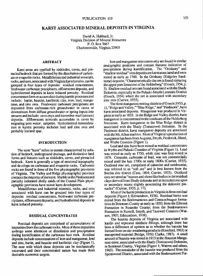
PUBLICATION 119
KARST ASSOCIATED MINERAL DEPOSITS IN VIRGINIA
David A. Hubbard, Jr.Virginia Division of Mineral Resources
P. O. Box 3657Charlottesville, Virginia 22903
135
ABSTRACT
Kant areas are typified by sinkholes, caves, and pin-nacled bedrock ttrat are formed by the dissolution of carbon-ate or evaporite rocks. Metalliferous and industrial minerals,rocks, andores, associated with Virginiakarstterrains, can begrouped in four types of deposits: residual concentrates,freshwater carbonate precipitates, efflorescent deposits, andhydrothermal deposits in karst induced porosity. Residualconcentrates form or accumulate during karstic processes andinclude: barite, bauxite, kaolinitic clay, iron, lead, manga-nese, and zinc ores. Freshwater carbonate precipitates aredeposited from carbonate-rich groundwater in caves ordownsEeam from diffuse groundwater or spring inputs inostreams and include: cave onyx and travertine-marl (sneam)deposits. Efflorescent minerals accumulate in caves bymigraring pore water: saltpetre. Hydrothermal mineraliza-tion in karstic porosity includes lead and zinc ores andprobably Iceland spar.
INTRODUCTION
The term "karst" refers to terrain characterized by solu-tion of bedrock, underground drainage, and distinctive landforms and features such as sinkholes, caves, and pinnacledbedrock. Karst is generally a type of erosional topographyand develops on carbonate and evaporite rocks. Carbonaterocks are found in three ofthe five physiographic provincesof Virginia. The Valley and Ridge physiographic provincecontains the majority of thekarst. Marble in thePiedmontandparrially indurated shelly sands of the Coastal Plain physi-ographic provinces have minor karst development.
Metalliferous and industrial minerals, rocks, and oresassociated with karst can be grouped into four types ofdeposits: residual concentrates, freshwater carbonate pre-cipitates, efflorescent deposits, and hydrothermal deposits inkarst induced porosity.
RESIDUAL CONCENTRATES
Re.sidual deposits are comprised of accumulations ofimpurities from the carbonate rocks. Mostof these impuritiasundergo some alteration or dissolution and precipitationduring karstification of the carbonate host rock. Residualdeposis include concentrations ofiron and manganese, leadand zinc, barite, and bauxite and kaolinitic clay (Figure 1).
The ease with which these deposits can be mechanicallyexcavated and their concentrated nature has made themdesirable economic targets.
hon and manganese ores commonly are found in similarstratigraphic positions and contain features indicative ofprecipitation during karstification. The "Oriskany" and
"shallow residual" iron deposits are karst associated and weremined as early as 1760. In the Oriskany S.idgeley Sand-
stone) deposits, "Characteristically the oreis foundreplacingthe upper pure limestone of the Helderberg" (Gooch, 1954,p.
3). Shallow residual ores are found associated with the Shady
Dolomite, especially in the Pulaski-Smyth Limonite District(Gooch, 1954) where the ore is associated with secondaryzinc ores (Currier, 1935).
The three manganesemining districts ofGooch (1955,p.
I ), "Ridge and Valley," "Blue Ridge," and "Piedmont", have
karst associated deposits. Manganese was produced in Vir-ginia as early as 1832. In the Ridge and Valley disnict" karstmanganese is concentrated in the residuum of the Helderberglimestone. Karst manganese in the Blue Ridge district isassociated with the Shady (Tomstown) Dolomite. In the
Piedmont district, karst manganese deposits are associated
with the Mt. Athos marbles. Most of Virginia's production ofmanganese has been from Augusta, Smyth, Frederick, Bland,
and Wythe Counties (Figure 1).
I-ead and zinc have been mined as residual concenEatesin Wythe and Pulaski Counties of Virginia (Figure 1). Leadwas mined as early as 1750, while zinc was first mined in1879. Cerussite, carbonate of lead, was not commerciallymined until the late 1700s or early 1800s (Cunier, 1935).
Oxidized zinc ore, comprised of calamine and smithsonite,was referred to as "soft ore" and is best known from the
Bertha zinc disrict (Case, 1894; Currier, 1935). Oxidized
ores occurred as "masses and sheet-like bodies in the residualclays derived from Shady dolomite and as incrustations upon
or secondary seams slightly penerating ttre dolomite pin-
nacles" (Currier, 1935, P. 7 7).Most of the barite production in Virginia is from residual
deposits (Figue 1; Edmundson ,1936). Residual barite was
mined from the Beekmantown and Conococheague forma-tions in Boteourt County as early as 1850; from the ElbrookFormation in Roanoke County; from tle BeekmantownFormation in Russell, Smyth, and Tazewell Counties (Wat-
son, 1907; Edmundson, 1938).The bauxite deposits of Virginia are associated with
kaolin and represent sinkhole fillings, although there has
been a difference of opinion as to whether the bauxite has
formed from on site weathering products (Knechtel, f 963) ortransporled material (Bridge, 1950; Clarke, 1987). A small
amount of bauxite was mined in I 9 1 5 at the Houson Manga-nesemine, associated with ttre Shady (Tomstown) Dolomite,in Botetourt County, Virginia @gure 1; Warren and others,
1965). The remainder of the bauxite was produced from ttre
Spottswood District, associated wittr the Beekmantown For-
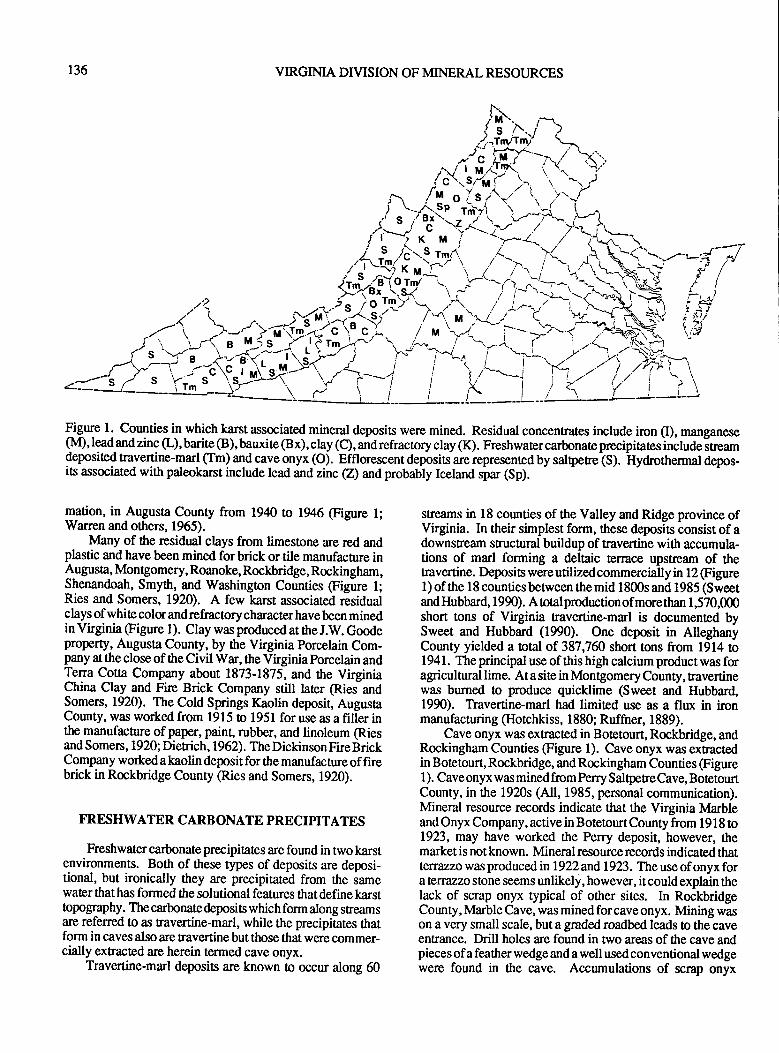
136 VIRGINIA DIVISION OF MINERAL RESOURCES
Figure 1. Counties in which karst associated mineral deposits were mined. Residual concentrates include iron (I), manganese(M),leadandzinc(L),barite@),bauxite@x),clay(C),andrefractoryclay(K). Freshwatercarbnateprecipitatesinclude'sneamdeposited travertine-marl (Tm) and cave onyx (O). Efflorescent depbsisare represented by saltperclS). Hydrothermal depos-its associated with paleokarst include lead and znc (z) and probably Iceland spu (sp).
mation, in Augusta County from 1940 to 1946 (Figure l;Warren and others, 1965).
lvlany of the residual clays from limestone are red andplastic and have been mined for brick or tile manufacture inAugusta, Montgomery, Roanoke, Rockbridge, Rockingham,Shenandoah, Smyth, and Washington Counties (Figure 1;Ries and Somers, 1920). A few karst associated residualclays of white color andrefraclory characler have been minedin Virginia (Figure 1). Clay was produced at theJ.W. Goodeproperty, Augusta County, by the Virginia Porcelain Com-pany at thecloseof the Civil War, the Virginiaporcelain andTerra Cotta Company about 1873-1875, and the VirginiaChina Clay and Fire Brick Company still later (RieJ andSomers, f920). The Cold Springs Kaolin deposit, AugustaCounty, was worked from 1915 to 1951 for use as a filier inthe manufacture of paper, paint, rubber, and linoleum @iesand Somers, 1920; Dierich, I 962). The Dickinson Fire BrickCompany worted akaolin deposit for the manufacture of firebrick in Rockbridge County @ies and Somers, 1920).
FRESHWATER CARBONATE PRECIPITATES
Freshwater carbonateprecipiarcs are found in two karstenvironments. Both of these types of deposits are deposi-tional, but ironically they are precipitated from the samewater that has formed the solutional features that define karsttopography. Thecarbonatedeposis which form along sFeamsare referred to as travertine-marl, while the precipitates thatform in caves also are travertine but those that werecommer-cially extracted are herein termed cave onyx.
Travertine-marl deposits are known to occur along 60
streams in 18 counties of the Valley and Ridge province ofVirginia. In their simplest form, these deposits consist of adownstream structural buildup of travertine with accumula-tions of marl forming a deltaic terrace upsheam of thetravertine. Deposits were utilized commercially in 12 (Figure1)of the 18 countiesbetrveen themid 1800sand 1985 (SweetandHubbard, 1990). A totalproduction ofmorethan 1,570,000short tons of Virginia travertine-marl is documented bySweet and Hubbard (1990). One deposit in AlleghanyCounty yielded a total of 387,760 short tons from 1914 to1941 . The principal use of this high calcium product was foragricultural lime. At a site in Montgomery County, Eavertinewas burned to produce quicklime (Sweet and Hubbard,1990). Travertine-marl had limited use as a flux in ironmanufacturing (Hotchkiss, I 880; Ruffrrer, 1889).
Cave onyx was extracted in Botetourt, Rockbridge, andRockingham Counties (Figure 1). Cave onyx was extractedin Botetourt, Rockbridge, and Rockingham Counties (Figure1). Cave onyx was minedfrom Perry SaltpetreCave, BotetourtCounty, in fte 1920s (All, 1985, personal communication).Mineral resource records indicate ttnt the Virginia Marbleand Onyx Company, active in Botetourt County from 1918 to1923, may have worked the Perry deposit, however, themarket is not known. Mineral resource records indicated thatterrazzo was produced in 1922 and 1923. The use of onyx fora terazzo stone seems unlikely, however, it could explain thelack of scrap onyx typical of other sites. In RockbridgeCounty, Marble Cave, was mined for cave onyx. Mining wason a very small scale, but a graded roadbed leads to the caveentrance. Drill holes are found in two areas of the cave andpieces of a feather wedge and a well used conventional wedgewere found in the cave. Accumulations of scrap onyx
PUBLICATION 119 137
indicate that the onyx was probably worked to block dimen-sions. The onyx was cut by a gang saw at Rapps Millaccording to local lore. The dates of mining and market forthis onyx is unknown. The Onyx Hill depositof RockinghamCounty was mined by the Virginia Minerals and MiningCompany accuding to the present landowner (PaulRohrer,1988, personal communication). Deed searches did not turnup any information on this company, however, they didreveal that the Virginia Onyx Company paid for property and
onyxrights atthis sitein 1893. Mining evidenceincludes twolarge onyx debris piles and a2- to l2-foot wide by 60-fmtlong by 15-fmt deep cut. Drill hole marks can be seen on
some of the onyx debris. The destination of this onyx and itseventual form are not known. The Miller onyx deposit ofRockingham County was reportedly worked between 1870and 1892 for ombsones (Hess, 1976). A second reference tothis site mentions that J.E. Miller and Sons "...began makingin 1892 tombstones of onyx found on ttreir land. They usedacircularrubbing bed operated by water power to polish thehard onyx" (t'/Iay,1976, p. 518). Several onyx gravestones
have been located at J.E. Miller's church (Beaver CreekChurch of the Bretlnen) in Rockingham County. The stones
are dated from 1852 ta 1872, but the date of the churchbuilding is 1868. Possibly the gravestones significantlypostdate theburials andeven the building of the church, or thegraves were moved to tle new church location after 1868.
Two additional onyx graveslones, dated 1860(?) and 1870,are located in the GreenWoodCemetery,approximately twomiles from the Miller deposit. Two pits, 25 feet by 50 feet by6- to 8-feet deep and 35 feet by 60 feet by l0-feet deep, and
two onyx debris piles are visible atthe Miller site. In 1892 the
Virginia Onyx Company was organized to mine and marketonyx (Allen, 1 893 ; May, 1 976). The Miller site was the initialholding of this company. In addition to the Miller and OnyxHill (Hinton) sites, onyx was reported from Garber's Church(May, 1976), but this site has not been located. The VirginiaOnyx Company is known to have "shipped a large um, twocones and apyramid made of beautifully dressed onyx to NewYork in February, 1897" (May, 1976, p. 519).
EFFLORESCENT DEPOSITS
Efflorescent deposits are formed by the precipitation ofminerals from pore water in rock or sediment. These mineralsare soluble and usually accumulate only in locations wherethe sediment or rock and air contacts are sheltered. Althoughsome of these minerals were utilizedprehistorically (Watson,
1974), the only minerals of historical economic concern inVirginia are nitrates. The nitrate minerals of interest are
nitrocalcite, nitromagnesite, and niter. The common namefor niter is saltpeter, the archaic spelling of which has beenused for the nitrate minerals mined from caves and refined forthe making of black powder (gunpowder). Saltpetre was avery important commodity when imports were restrictedduring the American Revolution, the War of 1812, and the
CivilWar. Within thepresentboundaries of Virginia, whichwere different during each of the above conflics,76 saltperecaves arc known in the Valley and Ridge physiographicprovince (Figure 1; Hubbard, 1988; Hubbard and others,
1939). Saltpetre mining relicts include the remains of leach-
ing vats, leachate and water collecting troughs, dtgging and
scraping tools, boiling kettles, and evidence of mining such
as leached petre dfut piles, digging matks, tally marks, and
torch perches.
HYDROTHERMAL DEPOSITS IN KARSTINDUCED POROSITY
The hydrothermal deposits in karst induced porosity are
generally associated with paleokarst. The paleokarst topo-graphic surface may have been destroyed or may be virnrallyunrecognized in the stratigraphic sequence and indicated
only by an unconformity. Irad and zinc deposits occurringin the Ordovician-aged Knox and Beekmantown carbonate
rocks have been identified as hydrothermal in origin and
associated with paleokarst. An optical grade calcite depositis included cautiously in this category, although further study
is needed for a definitive genesis of this deposit'Commercial deposits of zinc were deposited by mineral-
forming solutions in the paleoaquifer associated with the
Knox-Middle Ordovician unconformity, a former karst to-pography, at the top of the Mascot Dolomite in Tennessee and
iouthern Virginia (Hanis, 1971). The unconformity at the
top of the laterally equivalent Beekmantown Formation ofOidovician age was the karst surface associated with the
secondary permeability along which zinc and lead ores were
deposited in the cenrral and northern Valley and Ridgeprovince.
Icelandspar,a variety of calcite, was minedforis opticalproperties in the vicinity of Timberville, Virginia during thelgth century $igure 1). Located in the Ordovician-ageEdinburg Formation, the deposit is of probable hydrothermalorigin and may have been deposited along kant induced
porosity. Spar deposition on a solutional surface of Edinburglimesbne can be observed near the north end of the approxi-mately 300 foot by 5 to 20 foot site. Isotope work needs to be
done to determine the origin of the deposit.
FUTURE RESOURCE POTENTIAL
The potential for mineable manganese and clay, forrefractory and whiteware uses, deposits associated with karstexists in Virginia. The more challenging and rewardingdeposis will be associated with hydrothermal depositionasiociated with paleokarsl The identification of these sites
is dependent on the recognition ofboth compositional signa-
tures and paleosolutional features proximal to unconformi-ties and fauls capable of transmitting ore-bearing fluids.
World-wide, other ore-grade deposits of possible hydrother-mal and karst origin include copper, mercury, silver, ura-
nium, and vanadium (Quinlan, 1972).
REFERENCES CITED
Allen, R.B., 1893, Report for the Virginia Onyx Company:
company report of Virginia Onyx Company (available from
138 VIRGIMA DIVISION OF MINERAL RESOURCES
U.S. Geological Survey Library), p. 1-18.
Bridge, Josiah, 1950, Bauxite deposits of the southeasternUnited States, ln Snyder, F.G., ed., Symposium on mineralresources of the southeastern United States, 1949 proceed-ings: University of Tenness@ Press, p.170-201.
Case,W.H., lS94,TheBerthazinc-minesatBertha, Viryinia:American Institute of Mining Engineering Transact"ions, v.22,p.51I-536.
Clarke, O.M., Jr., 1987, Karst Bauxite deposits in the U.S.A.:TRAVAUX, v. 16-17,p. 1-11.
Currier, L.W., 1935, Lead and Zinc region of SouthwesternVirginia: Virginia Geological Survey Bulletin 43,122p.
Dietrich, R.V., 1962, Southern field excursion guidebook:Washington, D.C., Intemational Mineralogical Association,Third General Congress, 59 p.
Edmundson, R.S., 1936, Barite deposits of Virginia: Ameri-can Institute of Mining and Metallurgical Engineers, Techni-cal Publication No. 725, p.l-17.
Fdmundson, R.S., 1 938, Barite deposits of Virginia: VirginiaGeological Survey, Bullerin 53, 85 p.
Gooch,8.O., 1954, hon in Virginia: Virginia Division ofGeology Mineral Resources Circular No. l,17 p.
Gooch, E.O., 1955, Current manganese operations in Vir-ginia: Virginia Division of Geology, Virginia Minerals, v. I ,n. 5, p. 1-6.
l-farris, L.D., 1972, A lower Paleozoic paleoaquifer - theKingsportFormation and Mascot Dolomite of Tennessee andsouthwest Virginia: Economic Geology, v. 66, p. 735-743.
H€ss, N.B., 1976, The heartland "Rockingham County":Hanisonburg, Virginia, Park View Press, 375 p.
Hotchkiss, Jed, 1880, Marl as a blast fumace flux: TheVirginias, v. 1, n. 2,p. L73.
Hgbbard, Dave, 1988, Virginia saltpetre caves: Chantilly,Virginia, Virginia Cellars, v.2,n.1, p. 8-10.
Hubbard, D.A., Jr., Herman, J.S., Mitchell, R.S., and IIam-merschmidt, Elmar, 1989, Cave saltpetre: chemical, histori-cal and mineralogical aspects: Budapest, Hungary, proceed-ings-l0th International Congress of Speleology, p. 148-150.
Knechtel, M.M., 1963, Bauxitization of terra rossa in thesouthern Appalachian region: U.S. Geological Survey Professional Paper 475-C, p. Cl5 1-C155.
lday, C.8., 1976, Life under four flags in the North RiverBasin of Virginia: Verona, Virginia McClure Press, p. 518-519.
Quinlan, J .F., 1972, Karst-related mineral deposits and pos-sible criteria for the recognition ofpaleokarsts: A review ofpreservable characteristics of Holocene and olderkarst terra-nes: 24ttr International Geological Congress, Section 6 -Stratigraphy and Sedimentology, p. 156-168.
Ries, H., and Somers, R.E., 1920, The clays and shales ofVirginia west of the Blue Ridge: Virginia Geological SurveyBulletin 20, 118 p.
Ruffner, W.H., 1889, Report on the landed property of theBuena Vista Company: Philadelphia, Pennsylvania, DandoPrinting and Publishing Co., 354 p.
Sweet, P.C., and Hubbard, D.A., Jr., 1990, Economic legacyand disnibution of Virginia's Valley and Ridge provincetravertine-marl deposits, iz Herman, J.S., and Hubbard, D.A.,Jr., eds., Travertine-marl: stream deposits in Virginia: Vir-ginia Division of Mineral Resources Publication 101, p. 123-r32.
Warren, W.C., Bridge, Josiah, and Overstreet, E.F., 1965,Bauxite deposits of Virginia: U.S. Geological Suney Bulle-tin ll99-K, 17 p.
Watson, P.J., 1974, Archeology of the Mammoth Cave area:New York, New York, Academic Press, Inc.,255 p.
Watson, T.L., 1907 , Mineral Resources of Virginia: Lyn-chbug, Virginia, J.P. Bell Company, Printers and Binden,618 p.
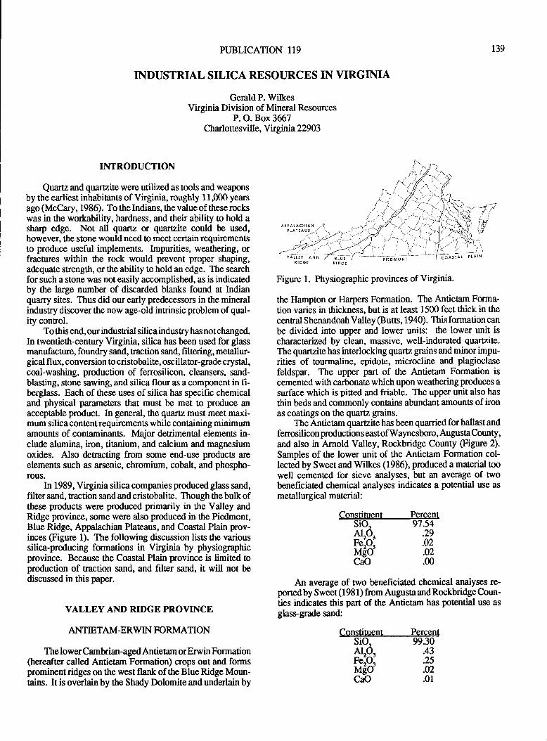
PUBLICATION II9
INDUSTRIAL SILICA RESOURCES IN VIRGINIA
GeraldP. WilkesVirginia Division of Mineral Resources
P. O. Box 3667Charlottesvill e, Y k gnia 22903
r39
INTRODUCTION
Quartz and quartzite were utilized as tools and weaponsby the earliest inhabiants of Virginia, roughly 1 I,000 yearsago (McCary, 1986). To the Indians, the value of these rockswas in tJre workability, hardness, and their ability to hold asharp edge. Not all quartz or quafrzite could be used,however, the stone would need o meet certain requirementsto produce useful implements. Impurities, weatlering, orfractures within the rock would prevent proper shaping,adequate strength, or the ability to hold an edge. The searchfor such a stone was not easily accomplished, as is indicatedby the large number of discarded blanks found at Indianquarry sites. Thus did ow early predecessors in the mineralindustry discover the now age-old intrinsic problem of qual-iry conrol.
To this end, our indusnial silica indusry has not changed.In twentieth-cen0lry Virginia, silica has been used for glassmanufacture, foundry sand, traction sand, filtering, metallw-gical flux, conversion to cristobalite, oscillator-grade crystal,coal-washing, production of fenosilicon, cleansers, sand-blasting, stone sawing, and silica flour as a component in fi-berglass. Each of these uses of silica has specific chemicaland physical parameters that must be met to produce anacceptable product. In general, the quartz must me€t maxi-mum silica content requirements while containing minimumamounts of contaminants. Major derimenal elements in-clude alumina, iron, titanium, and calcium and magnesiumoxides. Also detracting from some end-use products arcelements such as arsenic, chromium, cobalt, and phosptn-rous.
In 1989, Virginia silica companies produced glass sand,filter sand, traction sand and crisobalite. Though the bulk ofthese producfs werc produced primarily in the Valley andRidge province, some were also produced in the Piedmont,Blue Ridge, Appalachian Plateaus, and Coastal Plain prov-irrces (Figure 1). The following discussion lists the varioussilica-producing formations in Virginia by physiographicprovince. Because the Coastal Plain province is limited oproduction of traction sand, and filter sand, it will not bediscussed in this paper.
VALLEY AND RIDGE PROYINCE
ANTIETAM-ERWIN FORMATION
The lower Cambrian-aged Antietam or Erwin Formation(hereafter called Antietam Formation) crops out and formsprominent ridges on the west flank of the Blue Ridge Moun-tains. It is overlain by the Shady Dolomite and underlain by
Figure l. Physiographic provinces of Virginia.
tlre llampton or Harpen Formation. The Antietam Forma-tion varies in thickness, but is at least 1500 feet thick in thecenral Shenandoah Valley (Butts, 1940). This formation canbe divided into upper and lower units: the lower unit iscbarrcteraed by clean, massive, well-indurated quafizite.The quartzite has interlocking quartz grains andminor impu-rities of tourmaline, epidote, microcline and plagioclasefeldspar. The upper part of the Antietam Formation iscemented with carbonate which upon weathering produces a
surface which is pitted and friable. The upper unit also has
thin beds and commonly contains abundant amounts of ironas coatings on the quartz grains.
The Antieam quartzite has been quarriedforballastandfenosilicon productions east of Waynesboro, Augusta County,and also in Arnold Valley, Rockbridge County (Ftgure 2).Samples of fte lower unit of the Antietam Formation col-lected by Sweet and Wilkes (1986), produced a material toowell cemented for sieve analyses, but an aYeurge of twobeneficiated chemical analyses indicates a potential use as
metallurgical material:
Constituent Percent97.54
.29.02.02.m
An average of two beneficiated chemical analyses re-ported by Sweet (1981) from Augusta andRockbridge Coun-ties indicates this part of the Antietam has potential use as
glass-grade sand:
Constituent Percent99.30
.43
.25
.02
.01
sio"A"O"Fe,O.McoCaO
sio,
*3rMgoCaO
) - "t-i
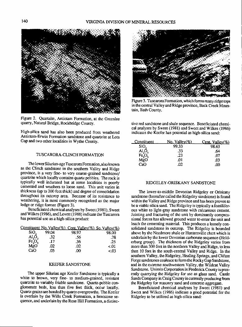
140 VIRGINIA DIVISION OF MINERAL RESOURCES
98.97 98.00.78.25
<.01<.03
Figure 2. Quartzite, Antietam Formation, at the Greenleequarry, Natural Bridge, Rockbridge County.
High-silica sand has also been produced from weatheredAntietam-Erwin Formation sandstone and quartzite at LotsGap and two orher localities in Wythe County.
TUSCARORA-CLINCH FORMATION
The lower Silurian-age TuscaroraFormation, also knownas the Clinch sandstone in the southem Valley and Ridgeprovince, is a very fine- to very coarse-gnined sandsone/quartzite which locally contains quartz pebbles. The rock istypically well indwated but ar some localities is poorlycemented and weathers to loose sand. This unit varies inthickness (up to 200 feet thick) and degree of consolidationthroughout iE outcrop area. Because of its resistance toweathering, it is most commonly recognized as the majorledge or ridge former Sigure 3).
Beneficiated chemical analyses by Sweet (1981), Sweetand Wilkes (1986), and Lovett (1988) indicate the Tuscarorahas potential use as a high-silica product:
Constituent No. Valley(7o) Cent. Valley(7o) So. Valle),(Zo)sio2 99.MNro3 '32 .56
Figure 3. TuscaroraFormation, which forms manyridgetopsin the central Valley and Ridge province, Back Creek Moun-tain, Bath County.
tive red sandstone and shale sequence. Beneficiated chemi-cal analyses by Sweet (1981) and Sweet and Wilkes (1986)indicates the Keefer has potential as high-silica sand:
Constituent No. Valle],(7o) Cent. Valley(7o)
KEEFER SANDSTONE
The upper Silurian age Keefer Sandstone is typically awhite to brown, very fine- to medium-grained, resistantquartzite to variably friable sandstone. Quartz-pebble con-glomerate beds, less than five feet thick, occur locally.Quartz grains are bonded by quartz overgrowths. The Keeferis overlain by the Wills Creek Formation, a limestone se-quence, and underlain by the Rose Hill Formation, a distinc-
sio2AP,Fe' ,MgoCaO
99.33 98.63
RIDGELEY.ORISKAI{Y SANDSTONE
The lower-to-middle Devonian Ridgeley or Oriskanysandstone (hereafter called the Ridgeley sandstone) is foundwithin the Valley and Ridge province and has been proven tobe a viable silica sand. The Ridgeley is typically a fossilifer-ous white to light-gray sandstone with calcareous cement.Jointing and fracturing of fte unit by dominantly compres-sional forces has allowed gfound water to enter the unit andleach the cementing material. This produces a loosely con-solidated sandstone in outcrop. The Ridgeley is boundedabove by the Needmore shale or Huntersville chert which isunderlain by the lower Devonian carbonate sequence (Held-erburg group). The thickness of the Ridgeley varies frommore tlan 300 feet in the northern Valley and Ridge, to lessthan l0 feet in the south-cenral Valley and Ridge. In thesouthem Valley, the Ridgeley, Healing Springs, and CliftonForge sandstones coalesce to form the Rocky Gap Sandstone,and in the extreme soutlwestem Valley, the Wildcat ValleySandstone. Unimin Corporation in Frederick County is pres-ently quarrying the Ridgeley for use as glass sand. CastleSands Company in CraigCounty is currently producingfromthe Ridgeley for masonry sand and concrete aggregate.
Benehciated chemical analyses by Sweet (1981) andSweet and Wilkes (1986) indicate a good potential for theRidgeley to be utilized as high-silica sand:
.&
.07
.03
.m
.33
.23
.01
.42
FeP, .17 .36MgO .02 .02CaO .05 .00
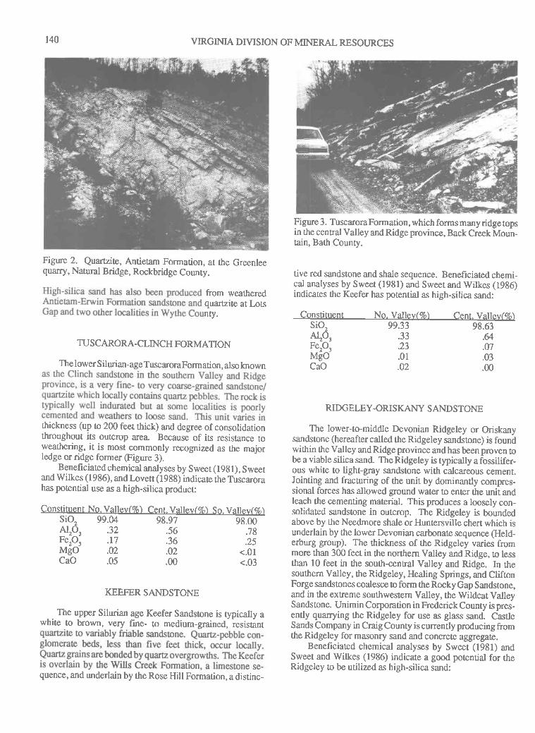
140 VIRGINIA DIVISION OF MINERAL RESOURCES
Figure 2. Qtarrzik, Antietam Formation, at the Greenleequarry, Natural Bridge, Rockbridge County.
from weatheredquartzite at L,otsnty.
TUSCARORA-CLINCH FORMATION
The lower Silurian-age TuscaroraFormation, also lnown
thickness (up o 200 feet rhick) and degree ofconsolidarionthroughout its outcrop area. Because of its resistance toweathering, it is most commonly recognized as the majorledge or ridge former @igure 3).
Beneficiated chemical analyses by Sweet (19g1), Sweetand Wilkes (1986), and Lovett (1988) indicate the Tuscarorahas potential use as a high-silica product:
Cons dtUen t No. Vallel,(7o) Cent. Valley ( 7o) S o. Valle],(Zo )sio2 99.u 98.97 98J0NP, .32 .s6 .78F"P, .17 .36 .25MgO .02 .02 <.01CaO .05 .00 <.03
KEEFER SANDSTONE
The upper Silurian age Keefer Sandstone is typically awhite to brown, very fine- to medium-grained, resistant
quence, and underlain by the Rose Hill Formation, a distinc-
Figure 3. Tuscarora Formation, which forms many ridge topsin the central Valley and Ridge province, Back Creek Moun-tain, Bath County.
tive red sandstone and shale sequence. Beneficiated chemi-cal analyses by Sweet (1981) and Sweet and Wilkes (1936)indicates the Keefer has potential as high-silica sand:
Constituent No. Valley(7o) Cent. Vallev(Zo)sio2AP,F"P,MgoCaO
99.33 98.63.33.23.01.02
.&
.07
.03
.m
RIDGELEY.ORIS KANY SANDSTONE
The lower-to-middle Devonian Ridgeley or Oriskanysandstone (hereafter called the Ridgeley sandstone) is foundwithin the Valley and Ridge province and has been proven tobe a viable silica sand. The Ridgeley is rypically a fossilifer-ous white to light-gray sandstone with calcareous cement.Jointing and fracturing of the unit by dominantly compres-sional forces has allowed gtound water to enter the unit andleach the cementing material. This produces a loosely con-solidated sandstone in outcrop. The Ridgeley is boundedabove by the Needmore shale or Huntersville chert which isunderlain by the lowerDevonian carbonate sequence (Held-erburg group). The thickness of the Ridgeley varies frommore than 300 feet in the northern Valley and Ridge, to lessthan l0 feet in the south-cenral Valley and Ridge. In thesouthern Valley, the Ridgeley, Healing Springs, and CliftonForge sandstones coalesce to form the Rocky Gap Sandstone,and in the extreme southwestem Valley, the Wildcat ValleySandstone. Unimin Corporation in Frederick County is pres-ently quarrying the Ridgeley for use as glass sand. CastleSands Company in Craig County is currently producing fromthe Ridgeley for masonry sand and concrete ag$egate.
Benefrciated chemical analyses by Sweet (1981) andSweet and Wilkes (1986) indicare a good potential for rheRidgeley to be utilized as high-silica sand:
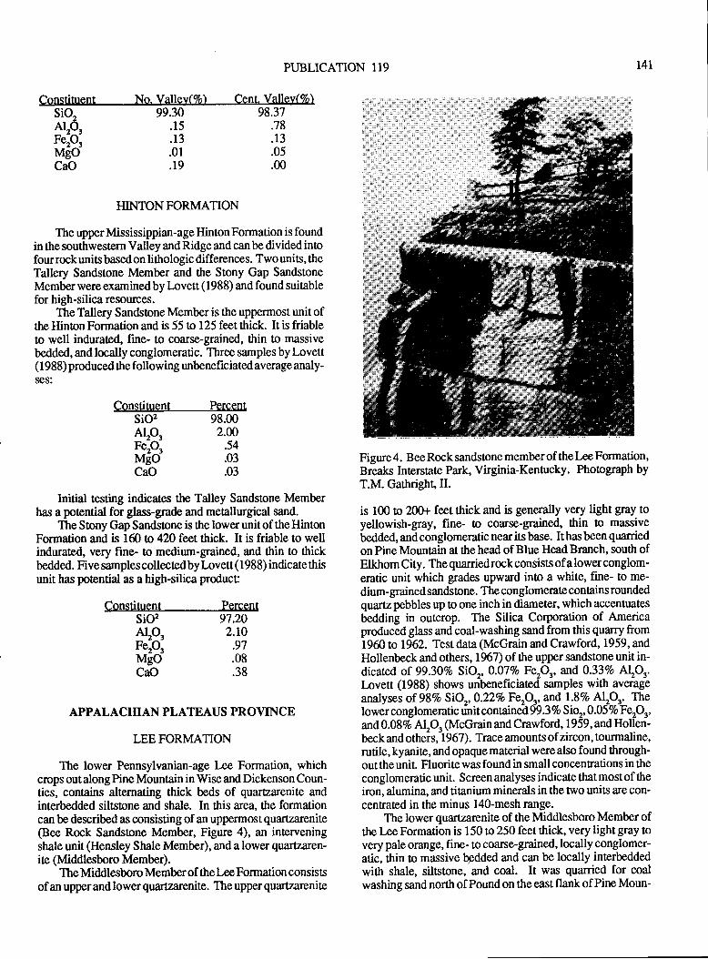
PUBLICATION 119
Constituent No. Valley(7o) Cent. Valle)'(7o) , :,
141
sio2AP'FeP,MsoCaO
99.30.15.13.01.19
98.37.78.13.05.00
HINTONFORMATION
The upper Mississippian-age Hinton Formation is foundin the southwestern Valley and Ridge and can be divided inofour rock units based on lithologic differences. Two units, theTallery Sandstone Member and the Stony Gap SandstoneMemberwereexaminedby lnvett (1988) and found suitablefor high-silica resources.
The Tallery Sandstone Member is the uppermost unit ofthe Hinton Formation and is 55 to 125 feet tltick. It is friableto well indurated, fine- to coarse-grained, thin to massivebedded, and locally conglomeratic. Three samples by Lovett( 1988) produced the following unbeneficiated average analy-ses:
Constituent Percentsio,NP,F"P,MgoCaO
98.002.00
.54
.03
.03
Initial testing indicates the Talley Sandstone Memberhas a potential for glass-grade and metallurgical sand.
The Stony Gap Sandsrone is the lowerunitof theHintonFormation and is lCI ta 420 feet thick. It is friable to wellindurated, very fine- lo medium-grained, and tlin to thickbedded. Five samples collectedby lovett ( 1988) indicate thisunit has potential as a high-silica produc[
Constituent Percent97.202.r0
.97
.08
.38
Figure 4. Bee Rock sandstone member of the Lee Formation,Breaks Interstate Park, Virginia-Kentucky. Phoograph byT.M. Gathright,II.
is 100 to 20Gr feet thick and is generally very light gray toyellowish-gray, fine- to coarse-grained, thin to massive
bedded, and conglomeratic near its base. It has been quarried
on Pine Mountain at the head of Blue Head Branch, south ofElkhom City. The quarriedrockconsists ofa lower conglom-eratic unit which grades upward into a white, fine- to me-
dium-grained sandstone. The conglomerate contains roundedquartz pebbles up to one inch in diameter, which accentuates
bedding in outcrop. The Silica Corporation of Americaproduced glass and coal-washing sand from this quarry from1960 to 1962. Test data (McGrain and Crawford, 1959, andHollenbeck and others, 1967) of the upper sandstone unit in-dicated of 99.307o SiO., 0.077o FeoO", and 0.33Vo A\O^'Invett (1988) shows uribeneficiated samples with averag-e
analyses of 98Vo5iO",0.227o Fe.O,, andl.SVo Al,O.. Thelower conglomeratic uiit conrainet 99.3 Vo Sio",0.\SVoF P'and 0.087o Al"O. (McGrain and Crawford, 1959, and Hollen-beck and otheis, 1967). Trace amounts of zircon, tourmaline,rutile, kyanite, and opaque material were also found through-out the unit. Fluorite was found in small concentrations in the
conglomeratic unit. Screen analyses indicate thatmostof theiron, alumina, and titanium minerals in the two units are con-centrated in the minus 140-mesh range.
The lower quutzarenite of the Middlesboro Member ofthe l-ee Formation is 150 to 250 feet thick, very light gray tovery pale orange, fine- to coarse-grained, locally conglomer-atic, thin to massive bpdded and can be locally interbedded
wittr shale, siltstone, and coal. It was quanied for coalwashing sand north of Pound on the east flankof Pine Moun-
sio,AlP3F"P,MgoCaO
APPALACMAN PLATEAUS PR OYINCE
LEE FORMATION
The lower Pennsylvanian-age Lee Formation, whichcrcps out along Pine Mountain in Wise and Dickenson Coun-ties, concains alternating thick beds of quartzarenite andinterbedded siltstone and shale. In this atea, the formationcan be described as consisting of an uppermost quailzarenite(Bee Rock Sandstone Member, Figure 4), an interveningshale unit (Hensley Shale Member), and a lower quafizarcn-ite (Middlesboro Member).
The Middlesboro Member of thel-ee Formation consiseof an upper and lower quartzarenite. The upper quartzarenite

PUBLICATION I19
Constituent No. Valley(7o) Cent. Vallel,(7o)98.37
.78
.13
.05
.00
HINTON FORMATION
The upper Mississippian-age Hinton Formation is foundin the southwestern Valley andRidgeand canbe dividedintofour rock units based on lithologic differences. Two units, theTallery Sandstone Member and the Stony Gap SandstoneMemberwere examinedbyLovett (1988) and found suitablefor high-silica resources.
The Tallery Sandsone Member is the uppermost unit ofthe Hinton Formation and is 55 to 125 feet thick. It is friableto well indurated, firne- to coarse-grained, thin to massivebedded, and locally conglomeratic. Three samples by Lovett( I 988) produced the following unbeneficiated average analy-ses:
Constituent Percentsio, 98.00NP, 2.00F"P, .54MgO .03CaO .03
Initial testing indicates the Talley Sandstone Memberhas a potential for glass-grade and metallurgical sand.
The Stony Gap Sandsone is the lower unit of the HintonFormation and is 160 tD 420 feet thick. It is friable to wellindurated, very fine- to medium-grained, and thin to thickbedded. Five samples collected by Lovett ( I 98 8) indicate thisunit has potential as a high-silica product
Constituent Percent97.202.r0
.97.08.38
APPALACHIAN PLATEAUS PROVINCE
LEE FORMATION
The lower Pennsylvanian-age l-ee Formation, whichcrops out along Pine Mountain in Wise and Dicken son Coun-ties, contains alternating thick beds of quartzarenite andinterbedded silstone and shale. In this alea, the formationcan be described as consisting of an uppermost quartzarenite(Bee Rock Sandstone Member, Figure 4), an inteweningshale unit (Hensley Shale Member), and a lower quartzaren-ite (Middlasboro Member).
The Middlesboro Member of the Lee Formation consistsof an uppe.r and lower quartzarenite. The upper quartzarenite
Figure 4. Bee Rock sandstone member of the Lee Formation,Breaks Interstate Park, Virginia-Kentucky. Phoograph byT.M. Garhright,II.
is 100 o 20Gr feet thick and is generally very light gray toyellowish-gray, fine- to coarse-grained, thin to massivebedded, and conglomeratic near its base. It has been quarriedon Pine Mountain at the head of Blue Head Branch, south ofElkhom City. The quanied rock consists of a lower conglom-eratic unit which grades upward into a white, fine- to me-dium-grained sandstone. The conglomerate contains roundedquartz pebbles up to one inch in diameter, which accentuatesbedding in outcrop. The Silica Corporation of Americaproduced glass and coal-washing sand from this quarry from1960 to 1962. Test data (McGrain and Crawford, 1959, andHollenbeck and others, 1967) of the upper sandstone unit in-dicated of 99.30Vo SiOr,0.07Vo F"P' and 0.33Vo A\Or.Lovett (1988) shows unbenef,rciated samples with averageanalyses of 98VoSiOr,O.22Vo FerO' andl.SVo Alp' Thelower conglomeratic unit contuned99.3Vo Sior, 0.05 7o Fep'and 0.087o AlO, (McGrain and Crawford, 1959, and Hollen-beck and others, 1967). Trace amounts of zircon, tourmaline,rutile, kyanite, and opaque material were also found through-out the unil Fluorite was found in small concentrations in theconglomeratic unit. Screen analyses indicate that most of theiron, alumina, and titanium minerals in the two units are con-centrated in the minus 140-mesh range.
The lower quartzarenite of the Middlesboro Member ofthe I,ee Formation is 150 to 250 feet thick, very light gray tovery pale orange, fine- to coarse-grained, locally conglomer-atic, thin to massive bgdded and can be locally interbeddedwitlr shale, siltstone, and coal. It was quarried for coalwashing sand north of Pound on the east flank of Pine Moun-
t4l
sio2 99.30a,o" .15reioi .13MgO .01CaO .19
sio2NP,FeP,MgoCaO
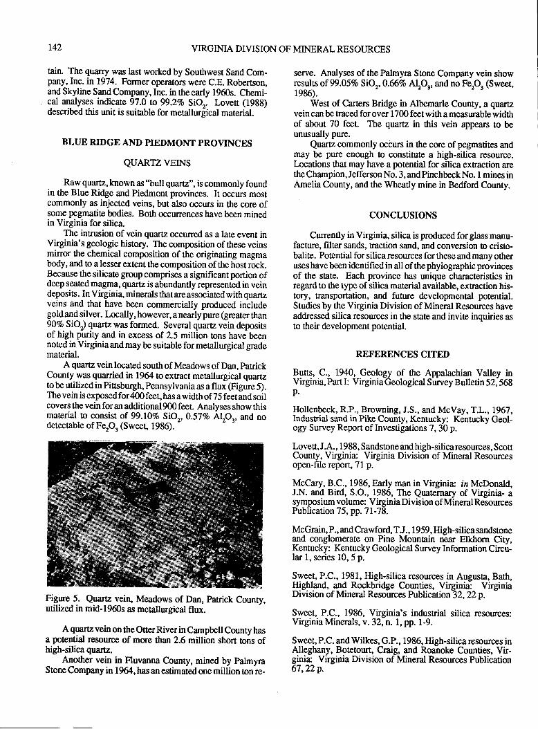
r42 VIRGINIA DIVISION OF MINERAL RESOURCES
tain. The quarry was last worked by Southwest Sand Com-pany, Inc. in1974. Former operators were C.E. Robertson,and Skyline Sand Company, Inc. in the early 1960s. Chemi-cal analyses indicate 97.0 to 99.27o SiO,. Loven (1938)described this unit is suitable for metallurgical material.
BLUE RIDGE AND PIEDMONT PROVINCES
QUARTZVEINS
Raw quartz,known as "bull quartz", is commonly foundin the Blue Ridge and Piedmont provinces. It occurs mostcommonly as injected veins, but also occurs in the core ofsome pegmatite bodies. Both occurrences have been minedin Virginia for silica-
The intrusion of vein quartz occurred as a late event inVirginia's geologic history. The composition of these veinsmirror the chemical composition of the originating magmabody, and to a lesser extent the composition of the host rock.Because the silicate group comprises a significantportion ofdeep seated magma, quartz is abundantly represented in veindeposis. In Virginia, minerals thatare associated with quartzveins and that have been commercially produced includegold and silver. Locally, however, a nearly pure (greater than907o SiOr) quartz was formed. Several quartz vein depositsof high purity and in excess of 2.5 million tons have beennoted in Virginiaand may be suitable formetallurgical gradematerial.
A quartz vein located south of Meadows of Dan, patrickCounty was quarried n 19& to extract metallurgical quartzto be utilized in Pittsburgh, Pennsylvania as a flux (Figure 5).The vein is exposed for 400 feet, has a width of 75 feet and soilcovers the vein for an additional g00 feet Analyses show thismaterial to consist of 99.l0Vo SiO, O.57Vo Alp., and nodetectable of Fep, (Sweet, 1986).
-
Figure 5. Quartz vein, Meadows of Dan, Panick County,utilized in mid-1960s as merallurgical flux.
A quartz vein on the Ouer River in Campbell County hasa potential resource of mse than 2.6 million short tons ofhigh-silica quartz.
Another vein in Fluvanna County, mined by palmyraStone Company in 1964, has an estimated one million ton re-
serve. Analyses of the Palmyra Stone Company vein showresults of 99.05Vo SiOr,0.667o AtO' and no Fep, (Sweet,1986).
West of Carters Bridge in Albemarle County, a quartzvein can be traced for over 1700 feet with a measurable widthof about 70 feet. The quartz in this vein appears to beunusually pure.
Quaru commonly @curs in the core of pegmatites andmay be pure enough to constitute a high-silica resource.lncations that may have a polential for silica exEaction arethe Champion, Jefferson No. 3, and Pinchbeck No. 1 mines inAmelia County, and the Wheatly mine in Bedford County.
CONCLUSIONS
Cunently in Virginia, silica is produced for glass manu-facture, filter sands, traction sand, and conversion to cristo-balite. Potential for silica resources for these and many otheruses have been identified in all ofthe phyiographic provincesof the state. Each province has unique characteristics inregard to the type of silica material available, extraction his-tory, transportation, and future developmental potential.Studies by the Virginia Division of Mineral Resources haveaddressed silica resources in the state and invite inquiries asto their development potential.
REFERENCES CITED
Butts, C., 1940, Geology of ttre Appalachian Valley inVirginia, Part I: Virginia Geological Survey Bulletin 52,568p.
Hollenbeck, R.P., Browning, J.S., and McVay, T.L., 1967,Indusrial sand in Pike County, Kentucky: Kentucky Geol-ogy Survey Report of Investigations 7, 30 p.
Lovett, J.A., 1988, Sandstone and high-silicaresources, ScottCounty, Virginia: Virginia Division of Mineral Resourcesopen-file report, 7l p.
McCary, 8.C., 1986, Early man in Virginia: in McDonald,J.N. and Bird, S.O., 1986, The Quaternary of Virginia- asymposium volume: Virginia Division of Mineral ResourcesPublication 75, pp. 7l-78.
McGrain, P., and Crawford, TJ., 1959, High-silica sandsloneand conglomerate on Pine Mountain rear Elkhorn City,Kentucky: Kentucky Geological Survey Information Circu-lar 1, series 10, 5 p.
Sweet, P.C., 1981, High-silica resources in Augusta, Bath,$iglland, and Rockbridge Counties, Virginia: VirginiaDivision of Mneral Resources Publication 32,22p.
Sweet, P.C., 1986, Virginia's indusuial silica resources:Virginia Minerals, v.32,n.1, pp. 1-9.
Sweet, P.C. and Wilkes, G.P., 1986, High-silica resources inAlleghany, Botetourt, Craig, and Roanoke Counties, Vir-ginia: Virginia Division of Mineral Resources Publication67,22p.
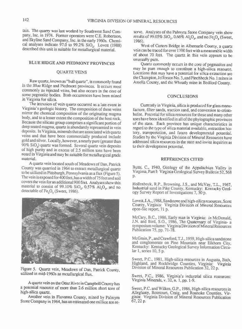
r42 VIRGINIA DIVISION OF MINERAL RESOURCES
tain. The quarry was last worked by Southwest Sand Com_
BLUE RIDGE AND PIEDMONT PROVINCF,S
QUARTZ VEINS
Raw quartz, known as "bull quaflz',, is commonly foundin the Blue Ridge and Piedmont provinces. It occurs mostcommonly as injected veins, but also occurs in the core ofsome pegmatite bodies. Both occurrences have been minedin Virginia for silica
The intrusion of vein quartz occurred as a late event in
noted in Virginia and may be suitable for metallurgical gradematerial.
feel Analysesshowthis
,,0.57Vo A!O' and no
Figyre 5. Qgarc vein, Meadows of Dan, patrick County,utilized in mid-1960s as mecallurgical flux.
A quarz vein on the Otrer River in Campbell County hasa potential resouce of mue than 2.6 million short tons ofhigh-silica quartz.
Another vein in Fluvanna County, mined by palmyraStone Company in 1964, has an estimated one million on re-
serve. Analyses of the Palmyra Stone Company vein showresults of 99.05Vo SiO,,0.66Vo Atq,and no Fep, (Sweet,1e86).
West of Carters Bridge in Albemarle County, a quartzvein can be traced for over 1700 feet wittr a measurable widthof about 70 feet. The quartz in ttris vein appears to beunusually pure.
Quartz commonly occurs in the core of pegmatites andmay be pure enough to constitute a high-silica resource.Locations that may have a potential for silica extraction arethe Champion, Jefferson No. 3, and Pirrchbeck No. I mines inAmelia County, and the Wheatly mine in Bedford County.
CONCLUSIONS
Cunently in Virginia, silica is produced for glass manu-facture, hlter sands, traction sand, and conversion o cristo-balite. Potential foruses havebeen idenof the state. Eachregard to the type of silica material available, extraction his-tory, transportation, and future developmental potential.Studies by the Virginia Division of Mineral Resources haveaddressed silica resources in the state and invite inquiries asto their development potential.
REFERENCES CITED
P_gtt!, C.. 1940, Geology of the Appalachian Valley inVirginia, Part I: Virginia Geological Suney Bullerin 52;568p.
Hollenbec McVay, T.L.,1967,Industrial ky: Kentucky Geol-ogy Surve 30p.
Lovett, J.A, 1988, Sandstone and high-silica resources, ScottCounty, Virginia: Virginia Division of Mineral Resourcesopen-file report, 7l p.
man in Virginia:The Qrntemary
iaDivisionofMin
, Bath,irgnia
Sweet, P.C., 1986, Virginia's industrial silica resources:Virginia Minerals, v.32,n.1, pp. 1-9.
Sweet,P.C.Alleghany,ginia: Virg67,22p.
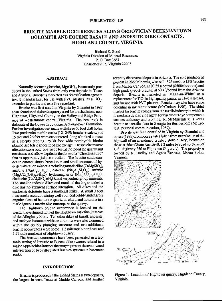
PUBLICATTON 119 r43
BRUCITE MARBLE OCCURRENCES ALONG ORDOVICIAN BEEKMANTOWNDOLOMTTE AND EOCENE BASALT AND ANDESITE DIKE CONTACTS,
HIGHLAND COUNTY, VIRGINIA
Richard S. GoodVirginia Division of Mineral Resources
F. O. Box 3667Charlottesville, Virginia 22903
ABSTRACT
Naturally occurring brucite, Mg(O$, is currently pro-duced in $re United States from only nro deposits in Texasand Arizona. Brucite is marketed as a detoxificalion agent intextile manufacture, for use with PVC plastics, as a TiOr-extender in paints, and as a fire retardant.
Brucite was first noted in Virginia by Giannini in 1987at an abandoned dolomite quarry used for crushed stone nearHightown, Highland County, in the Valley andRidge Prov-ince of westernmost central Virginia. The host rock isdolomite of ttre Lower Ordovician Beekmantown Formation.Further investigation was made withthree 60 footdrillholes.Two predazzite marble zones (12- 24%obrucits + calcite) of1 5 feet and 26 feet were encountered along a kinked contactin a steeply drpping, 25-30 foot wide porphyritic biotiteplagioclase felsic andesite of Eocene age. The brucite marblealteration zone outcrops for 36 feet at the top of the quarry andcontinues at shallow depths in the form of a "Christmas tree"that is apparently joint-controlled. The brucite-calcite/an-desite contact shows brecciation and small amounts of hy-drated alteration minerals including monticellite (CaMgS iO),analcite (NaAlpu.Hp), natrolite (NazAlrsipr), artinite(MgrCOr(OfDr.3I{rO), hydromagnesite (Mgr(CO ) n.4\O,chab-azite (CaAlrSiO4.6[O, and serpentine group minerals.The smaller andlesite dikes and much of the larger andesitedike has no apparent surface alteration. All dikes and theenclosing dolomite have a northeast strike. A small 3 footdiatreme breccia containing well-rounded pebbly and sharplyangular clasts of hematitic quartzite, chert, and dolomite in amafic igneous matrix also outcrops in the quarry.
The Hightown brucite occwrence is located on thewestern, overturned limb of the Hightown anticline, just eastof the Allegheny Fronl Ten other dikes of basalt, andesite,and rachyte in contact with the dolomite were also exam inedwithin the doubly plunging structure and two additionalbrucite occurrences were noted: I .5 mile north-norttreast and1.75 mile northeast of Hightown quarry.
The brucite occurences have been generated in a tec-tonic setting of Jurassic to Eocene dike swarms related to amajor Appalachian hospot that may represent the reactivatedintersection of two rift-related fracture systems in basementrocks.
INTRODUCTION
Brucite is produced in the United States at two deposits,
ttre largest in west Texas at Marble Canyon, and another
recently discovered deposit in Arizona. The sole producer atpresent is RMcMinerals, who sell -325 mesh, >157o brucite
from Marble canyon, at $0'25 a pound ($500/short ton) and
high grade (>NVo brucite) at $0.40/pound fromrhe Arizonadeposir Brucite is marketed as "Magnum-White" as areplacement for TiO, in high quality paints, as a fire retardant,
and for use with PVC plastics. Brucite may also have somepotential in ink manufacture (McCreless, 1990). The chiefmarket for brucite comes from the textile industry in which itis used as a deoxifying agent for hazardous dye componenfs
such as antimony and bromine. R. McMinerals sells Texas
brucite to a textile plant in Georgia for this purpose (McCre-
less, personal communication, 1989).Brucite was first identified in Virginia by Giannini and
ottrers (1987) from loose shalesfallenfrom nearthe top of the
highwall of an abandoned crushed stone quarry, located onthe east side of State Road 640, 2.3 miles by road northeast ofU.S. Highway 250 at Hightown (Figure 1). The property is
owned by N. Dudley and Agnes Rexrode, Mount Solon,
Virginia.
Figure l. Location of Hightown quary, Highland County,
Virginia.
-t,l
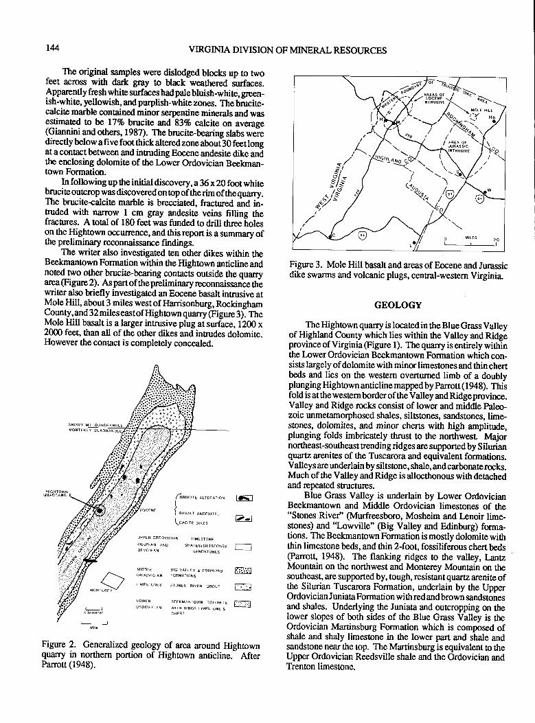
144 VIRGINIA DIVISION OF MINERAL RESOURCES
Figure 3. Mole Hill basalt and areas of Eocene and Jurassicdike swarms and volcanic plugs, central-western Virginia.
tD-t
e-l
wnr{aFrii.:l
GEOLOGY
The Hightown quarry is located in the Blue Grass Valleyof Highland County which lies within the Valley and Ridgeprovince of Virginia @igure I ). The quarry is entirely withinthe Lower Ordovician Beekmantown Formation which con-sists largely of dolomite with minor limestones and thin chertbeds and lies on the western overturned limb of a doublyplunging Hightown anticline mappedby Panott(1948). Thisfold is atthe westernborder of theValley andRidgeprovince.Valley and Ridge rocks consist of lower and middle paleo-zoic unmeiamorphosed shales, siltstones, sandstones, lime-stones, dolomites, and minor cherts with high amplitude,plunging folds imbricately thrust to the northwesl tvlajornortheast-southeast trending ridges are supportedby Silurianquartz arenites of the Tuscarora and equivalent formations.Valleys are underlain by siltstone, shale, andcarbona8erocks.Much of the Valley and Ridge is allocthonous with deachedand repeated structures.
Blue Grass Valley is underlain by Lower OrdovicianBeekmantown and Middle Ordovician limestones of the"Stones River" (Murfreesboro, Mosheim and Lenoir lime-stones) and "Lowville" (Big Valley and Edinburg) forma-tions. The Beekmantown Formation is mostly dolomite withthin limestone beds, and thin 2-foot, fossiliferous chert beds(Panott" 1948). The flanking ridges to the valley, LantzMountain on the northwest and Monterey Mountain on thesoutheast, are supported by, tough, resistant quartz arenite ofthe Silurian Tuscarora Formation, underlain by the UpperOrdovician Juniata Formation with red and brown sandstonesand shales. Underlying the Juniata and outcropping on thelower slopes of both sides of ttre Blue Grass Valley is theOrdovician Martinsburg Formation which is composed ofshale and shaly limestone in the lower part and shale andsandstone near the top. The Martinsburg is equivalent o theUpper Ordovician Reedsville shale and the Ordovician andTrenton limestone.
- The original samples were dislodged blocks up to twofeet rcross with dark gray !o black weathered s-urfaces.
lpnqgntly fresh white surfaces had pale bluish-whire, green-ish-white, yellowish, and purptsh-white zones. The bircite-calcite marble contained minor serpentine minerals and wasestimated ra be lTVo brucite and 83% calcite on average(Giannini and others, 1987). The brucite-bearing slabs weiedirectly below a five foot ttrick altered zone about 30 feet longat a contact between and intruding Eocene andesite dike andthe enclosing dolomite of the Lower Ordovician Beekman-town Formation.
In following up the initial discovery,t36x20 foot whitebtucite oqrcroprvas discovered on op of the rim of the quarry.The bnrcite+alcite marble is brecciated, fractured anC in-truded with narrow I cm gray andesite veins filling thefrachres. A total of 180 feet was funded to drill three f,oleson the Hightown occurrence, and this report is a summary ofthe preliminary reconnaissance findings.
The writer also investigated ten other dikes wittrin theBeekmantown Formation within the Hightown anticline andnofed two other brucite-bearing contacts outside the quarryarea @gure 2). As partof thepreliminary reconnaissance thbwriter also briefly investigated an Eocene basalt intrusive atMole Hill, about 3 miles west of llarrisonburg, RockinghamCounty, and 32 miles east of Highown quarry @gue 3). fheMole Hill basalt is a larger inrusive plug at surface, 1200 x2000 feet, than all of the other dikes and inrudes dolomite.However the contact is completely concealed.
MOXT€FEY QUAOq
MON T
AEEKMANTOWN OOLOMITE
WITH MINOR LIMESTONE &CHEFT
fnuc,-r o..enalo*
)
I ersert, eroesrre,
\DAC|TE DTKES
{.1r,s1::"-o:::l!
3.,;?
UPPERORDOVICIAN LIMESTONE
SIIURIAN ANO SHAL€S/SILTSTONESD€VONIAN SANDSTONES
MIODL€ AIG VAL'EY A EDINBORGORDoVIcIAN FoFMATIoNs
LIMESTONES STONES qIVEF GROUP-\*/
Figure 2. Generalized geology of area around Hightownquarry in northem portion of Hightown anticline.- AfterPanott (1948).
^']''-d/r*-"rp
,.t-.*fY/
7r++*effi,:h\./] ,"'"""'"./\\ .,("^ \,1:)* "'l'
"'--' ,/ \kr:\. H
/ / \r. ",/$o t' / \<'(
^a-t
(
0 MrrEs 20
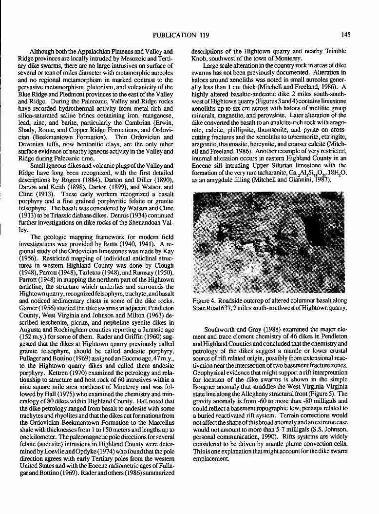
PUBLICATION 1T9 r45
Althoughboth the Appalachian Plateaus and Valley andRidge provinces are locally inruded by Mesozoic and Terti-ary dike swarms, there are no large intrusives on surface ofseveral or tens of miles diameter with metamorphic aureolesand no regional metamorphism in marked confrast to thepervasive metamorphism, plutonism, and volcanicity of theBlue Ridge and Piedmont provinces to the east of the Valleyand Ridge. During the Paleozoic, Valley and Ridge rockshave recorded hydrothermal activity from metal-rich andsilica-saurated saline brines containing iron, manganese,lead, zinc, and barite, particularly the Cambrian @rwin,Shady, Rome, and Copper Ridge Formations, and Ordovi-cian (Beekmantown Formation). Thin Ordovician andDevonian tuffs, now bentonitic clays, are the only othersurface evidence of nearby igneous activity in the Valley andRidge during Paleozoic time.
Small igneous dikes and volcanic plugs of the Valley andRidge have long been recognized, with the first detaileddescriptions by Rogers (1884), Darton and Diller (1890),Darton and Keith (1898), Darton (1899), and Watson andCline (1913). These early workers recognized a basaltporphyry and a fine grained porphyritic felsite or granitefelsophyre. The basalt was considered by Watson and Cline( 1 9 1 3) to be Triassic diabase dikes. Dennis ( I 934) continuedfurther investigations on dike rocks of the Shenandoah Val-ley.
The geologic mapping framework for modern fieldinvestigations was provided by Butts (1940, 1941). A re-gional study of the Ordovician limestones was made by Kay(1956). Resricted mapping of individual anticlinal sruc-tures in western Highland County was done by Clough(1948), Parroa (1948), Tarleton (1948), and Ramsay (1950).Parrott (1948) in mapping the northern part of the Hightownanticline, the structure which underlies and surrounds theHightown quarry, recognized felsophyre, trachyte, and basaltand noticed sedimentary clasts in some of the dike rocks.Gamer (1956) studied the dike swarms in adjacentPendletonCounty, West Virginia and Johnson and Milton (1963) de-scribed teschenite, picrite, and nepheline syenite dikes inAugusta and Rockingham counties reporting a Jurassic age(152 m.y.) for some of them. Rader and Griffin (1960) sug-gested that the dikes at Hightown quarry previously calledgranite felsophyre, should be called andesite porphyry.Fullager and Bottino ( 1 969) assigned an Eocene age, 47 m.y.,to the Hightown quarry dikes and called them andesiteporphyry. Kettren (1970) examined the petrology and rela-tionship to structure and host rock of 60 intrusives within anine square mile area northeast of Monterey and was fol-lowed by Hall (1975) who examined the chemistry and min-eralogy of 80 dikes within Highland County. Hall noted thatthe dike petrology ranged from basalt to andesite with sometrachytes andrhyolitesand that the dikes cut formations fromthe Ordovician Beekmantown Formation to the Marcellusshale with thicknesses from 1 to 150 meters and lengths up toone kilometer. The paleomagnetic pole directions for severalfelsite (andesite) intrusions in Highland County were deter-minedby Loevlie and Opdyke (1974) who found that the poledirection agrees with early Tertiary poles from the westernUnited States andwith the Eoceneradiomeric ages of Fulla-gar and Bottino ( 1 969). Rader and others (1 986) summarized
descriptions of the Hightown quarry and nearby TrimbleKnob, southwest of the town of Montercy.
Large scale alteration in the country rock in areas of dikeswarms has not been previously documented. Alteration inhaloes around xenotths was noted in small aureoles gener-
ally less than 1 cm thick (Mitchell and Freeland, 1986). Ahighly altered basaltic-andesitic dike 2 miles south-south-west of Hightown quarry (Figures 3 and4) contains limestonexenoliths up !o six cm across with haloes of melilite groupminerals, magnetite, and perovskite. Iater alteration of thedike converted the basalt to an analcite-rich rock with arago-nite, calcite, phillipsite, thomsenite, and pynte on cross-cutting fractures and the xenoliths to tobermorite, etFingite,aragonite, tlaumasite, hercynite, and coaner calcile (Mitch-ell and Freeland, 1986). Another example of very restricted,internal alteration occurs in eastem Highland County in anEocene sill intruding Upper Silurian limestone with theformation of the very rare tacharanite, Cqy'l2silsql.18I{2O,as an amygdule filling (Mitchell and Giannini, 1987).
Figure 4. Roadside outcrop of altered columnar basalt alongS tate Road 637, 2 miles south-southwest of Hightown quarry.
Southworth and Gray (1988) examined the major ele-ment and trace element chemistry of 46 dikes in Pendletonand Highland Counties and concluded that the chemisry andpetrology of the dikes suggest a mantle or lower crustalsource of rift related origin, possibly from extensional reac-tivation near the intersection of two basement fracture zones.
Geophysical evidence that might support arift interpretationfor location of the dike swarms is shown in the simpleBouguer anomaly that straddles the West Virginia-Virginiastate line along the Allegheny structural front @gure 5). Thegravity anomaly is from -60 to more than -80 milligals andcould reflect a basement topographic low, perhaps related toa buried reactivated rift system. Terrain corrections wouldnotaffectthe shape of thisbroad anomaly and an extreme casewould not amount to more than 5-7 milligals (S.S. Johnson,personal communication, 190). Rifts systems are widelyconsidered to be driven by mantle plume convection cells.This is one explanation that might account for the dike swarmemplacemenL
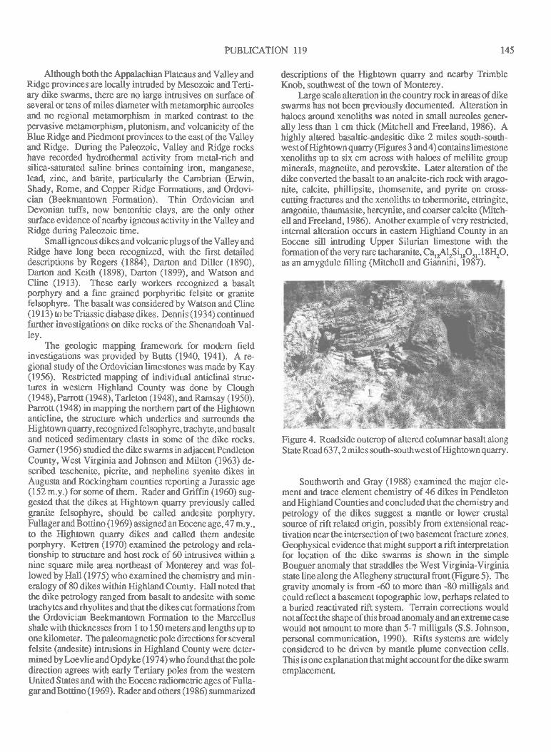
PUBLICATION II9 r45
Although bottr the Appalachian Plateaus and Valley andRidge provinces are locally intruded by Mesozoic and Terti-ary dike swanns, there are no large intnrsives on surface ofseveral or tens of miles diameter with metamorphic aureolesand no regional metamorphism in marked contrast to thepervasive metamorphism, plutonism, and volcanicity of theBlue Ridge and Piedmont provinces to the east of the Valleyand Ridge. During the Paleozoic, Valley and Ridge rockshave recorded hydrothermal activity from metal-rich andsilica-sanrated saline brines containing iron, manganese,lead, zinc, and barite, particularly the Cambrian @rwin,Shady, Rome, and Copper Ridge Formations, and Ordovi-cian (Beekmantown Formation). Thin Ordovician andDevonian tuffs, now bentonitic clays, are the only othersurface evidence of nearby igneous activity in the Valley andRidge during Paleozoic time.
Small igneous dikes and volcanic plugs of the Valley andRidge have long been recognized, with the first detaileddescriptions by Rogers (1884), Darton and Diller (1890),Darton and Keith (1898), Darton (1899), and Watson andCline (1913). These early workers recognized a basaltporphyry and a fine grained porphyritic felsite or granitefelsophyre. The basalt was considered by Watson and Cline( 1 9 I 3) to be Triassic diabase dikes. Denn is ( 1 934) continuedfurther investigations on dike rocks of the Shenandoah Val-ley.
The geologic mapping framework for modern fieldinvestigations was provided by Butts (1940, 1941). A re-gional study of the Ordovician limestones was made by Kay(1956). Resricted mapping of individual anticlinal sruc-tures in western Highland County was done by Clough(1948), Parroa (1948), Tarleton (1948), and Ramsay (1950).Parrott (1948) in mapping the northern part of the Highrownanticline, the structure which underlies and surrounds theHightown quarry, recognized felsophyre, tnchyte, and basaltand noticed sedimentary clasts in some of the dike rocks.Gamer (1956) studied ttre dike swarms in adjacent PendletonCounty, West Virginia and Johnson and Milton (1963) de-scribed teschenite, picrite, and nepheline syenite dikes inAugusta and Rockingham counties rcporting a Jurassic age(152 m.y.) for some of them. Rader and Griffin (1960) sug-gested that the dikes at Hightown quarry previously calledgranite felsophyre, should be called andesite porphyry.Fullager and Bottino ( I 969) assigned an Eocene age, 47 m.y.,to the Hightown quarry dikes and called them andesiteporphyry. Kettren (1970) examined the petrology and rela-tionship to structure and host rock of 60 intrusives within anine square mile area northeast of Monterey and was fol-lowed by Hdl (1975) who examined the chemisry and min-eralogy of 80 dikes within Highland County. Hall noted thatthe dike petr,ology ranged from basalt to andesite with sometrachytes and rhyolites and that the dikes cut formations fromthe Ordovician Beekmantown Formation to the Marcellusshale with thicknesses from I to 150 meters and lengths up toone kilometer. The paleomagnetic pole directions for severalfelsite (andesite) inmrsions in Highland County were deter-mined by l-oevlie and Opdyke ( 1 974) who found that the poledirection agees with early Tertiary poles from the westernUnited States andwith the Eoceneradiometric ages of Fulla-gar and Bottino ( I 969). Rader and others ( I 986) summarized
descriptions of the Highown quarry and nearby TrimbleKnob, southwest of the town of Mont€rey.
Iarge scale alleration in the country rock in areas of dikeswarms has not been previously documented. Alteration inhaloes around xenoliths was noted in small aureoles gener-ally less than I cm thick (Mirchell and Freeland, 1986). Ahighly altered basaltic-andesitic dike 2 miles south-south-west of Hightown quarry @gures 3 and4) contains limestonexenoliths up to six cm across with haloes of melilite groupminerals, magnetite, and perovskite. Later alteration of tlrcdike converted the basalt to an analcite-rich rock with arago-nite, calcite, phillipsite, thomsenite, and pynte on cross-cutting fractures and the xenoliths to tobermorite, ettringite,aragonite, thaumasite, hercynite, and coarser calcite Mtch-ell and Freeland, I 986). Another example of very restricted,internal alteration occurs in eastern Highland County in anEocene sill intruding Upper Silurian limestone with theformation of the very rare tacharanite, Cqy'lrSirrOsr.l84O,as an amygdule filling (Mitchell and Giannini, 1987).
Figure 4. Roadside outcrop of altered columnar basalt alongStateRoad637, 2 miles south-southwestofHightown quarry.
Southworth and Gray (1988) examined the major ele-ment and trace element chemistry of 46 dikes in PendletonandHighlandCounties andconcluded that the chemisry andpetrology of tlre dikes suggest a mantle or lower crustalsourc€ of rift related origin, possibly from extensional reac-tivation near the intersection of two basement fracture zones.Geophysical evidence that might support a rift interpretationfor location of the dike swarms is shown in the simpleBouguer anomaly that straddles the West Virginia-Virginiastate line along the Allegheny structural front (Figure 5). Thegravity anomaly is from -60 to more than -80 milligals andcould reflect a basement topographic low, pe.rhaps related toa buried reactivated rift system. Terrain corrections wouldnotaffect the shape of this broad anomaly and an exfreme casewould not amount to more than 5-7 milligals (S.S. Johnson,personal communication, 190). Rifts systems are widelyconsidered to be driven by mantle plume convection cells.This is one explanation that might account for the dike swarmemplacemenL

146
81"40" -l
.!
VIRGINIA DIVISION OF MINERAL RESOURCES
on Jchorlollesville
)l qo"
78"
I
39" i
Eoceneintrusion
ofHighlon,
Counly
38"
3T'
Figure 5. Eocene and Jurassic intrusions of west centralVirginia in relation to simple Bouguer gravity values.
RESULTS OF INVESTIGATION
The Beekmantown Formation at the Hightown quarrydips at about 75 degrees fo the southeast and is overturned tothe northwest. It is a bluish gray, ttrick bedded fine to mediumgrained dolomite with minor ttrin limestone beds. At ttrcupper highwall the dolomite is light gray @gure 6). Someexposures at the quarry are finely laminated and contain algalmat mudcracks indicating a peritidal shoreline environment(Frgure 7). In plain view there are three felsic biotite andesitedikes trending northeast cutting the dolomite beds @gure 8).A view of the quarry highwall showing exposures of the dikesnear and at the top is shown in Figure 9. Note the top of thedrill rig in the extreme op right corner showing the locationof drill holes # | md#2. The trvo dikes exposed in the quarryface are 3 to 5 feet wide and contain carbonate xenoliths attheir contacts. The andesite dike at the top of ttre high wall isabout 25-30 feet thick near the center of the quarry and dipssteeply to the southeast as does the dolomite which it cus.The andesite dike on the top of the quarry is gray to mediumgray with light gray in fresh core. It weatlrers to a brown,punky rock with biotite visible as hydrobiotite flakes in thesoil. The upper dike is porphyritic, with biotite, pyroxene,and plggioclase phenochrysts. The plagioclase phenochrystsare 1-2 mm wide laths 2-12 mm long and 10-l5mm rhombs,some of which might be sanidine. In thin secrion the plagio-clase is zoned and nnges from oligoclase to labradorite incomposition. Some grains show Carlsbad twinning. Thegroundmass is microcrysalline plagioclase, homblende, andcontains accessory magnetite, pynte, and apatite. The dikecontactwith theBeekmantown dolomite on a slopeback fromtte quarry face on the southern end of the quarry shows no
Figure 6. View to northeast from top of Hightown quarry ofexposures of Beekmantown dolomi0e.
Figure 7. Algal mudcracks on surface of steeply dipping,overturned beds of Beekmantown dolomite. View is tosoutheast and scale is indicated by hardhaf
HIGHIOWN OUABRY
HIGHLAXD COUNIY. VIAGINIA
ro,{r aBUL,rr LArc,rr v^"e,' fll(PR€DAZZITE)
EOCENE ANDESITE OIKE
LOWEA A€€KMA{IOWN
OFDOVICIAI OOLOMIIE
ffiE
t
Figure 8. Geologic map, pliain view, Hightown quarry.
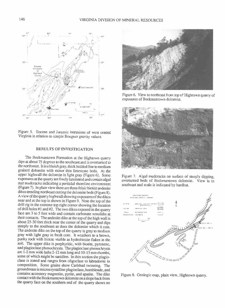
T46 VIRGINIA DIVISION OF MINERAL RESOURCES
81" 80. 79. 78.40. i
tigure 6. View to northeast fiom top of Hightown quarry of)xposures of BeekmanOwn dolomite.)xposures of BeekmanOwn dolomite.
)tMdt- |
| .--/i .\gr'^
l4;<;-*; ) t?h;;""," o
*'Lovt':L"
-."o@/re/- .ll aoorohe o ro
)/ .ao"1 / v,rtsJ7.)L 1 / 1L I I r37"
78"
Figure 5. Eocene and Jurassic intrusions of west centralVirginia in relation to simple Bouguer glavity values.
RESULTS OF INVESTIGATION
The Beekmantown Formation at the Highown quarrydips at about 75 degrees to the southeast and is overtumed tothe northwest. It is abluish gray, ttrick bedded fine to mediumgrained dolomite with minor thin limestone beds. At theupper highwall the dolomite is light gray (Figure 6). Someexposures at the quarry are finely laminated and contain algalmat mudcracks indicating a peritidal shoreline environment(Frgure 7). In plain view there are tluee felsic biotite andesitedikes trending northeast cutting the dolomite beds (Figure g).A view of the quarry highwall showing exposures of ttrl dikes
The andesite dike on the top of the quarry is gray to mediumgray with light gray in fresh core. It weathen to a brown,punky rock wittr biotite visible as hydrobiotite flakes in thesoil with biotite, pyroxene,ard agioclasephenochryssarc and 10-15 mm rhombs,some of which might be sanidine. In thin section the plagio-clase is zoned and ranges from oligoclase to labradorite in
Figure 7. Algal mudcracks on surface of steeply dipping,overturned beds of Beekmantown dolomite. View is tosoutheast and scale is indicated by hardhaf
HIGHLAND COUNTY VIRGINIA
eRU' rrr - catr.rrr '^""' nIPREDAZZITE)
A{D€SIIF OIKT
LOWEN BEEKMANIOWN
mE
Figure 8. Geologic map, pliain view, Hightown quarry.
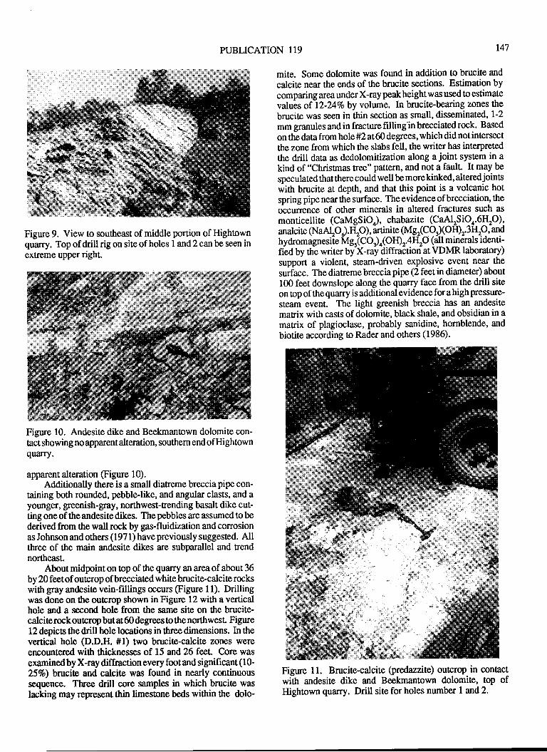
PUBLICATION 119 t4'l
Figure 9. View to southeast of middle portion of Hightownquarry. Top of drill rig on site of holes I and 2 can be seen inextreme upper right.
Figure 10. Andesite dike and Beekmanlown dolomite con-trct showing no apparent alteration, southem end of Hightownquarry.
apparent alteration (Figure 10).Additionally there is a small diatreme breccia pipe con-
taining both rounded, pebble-like, and angular clasts, and ayounger, greenish-gray, northwest-trending basalt dike cut-ting one of the andesite dikes. The pebbles are assumed to bederived from the wall rock by gas-fluidization and corrosionas Johnson and others (197 1) have previously suggested. Allthree of the main andesite dikes are subparallel and trendnortheast.
About midpoint on lop of ttre quarry an area of about 36by 20 feet of outcrop of brecciated white brucite-calcite rockswith gray andesite vein-fillings occurs (Figure l1). Drillingwas done on the outcrop shown in Figure 12 with a verticalhole and a second hole from the same site on the brucite-calciterockoutcrop but at60degrees o the northwesl Figure12 depics the drill hole locations in three dimensions. In thevertical hole (D.D.H. #l) two brucite-calcite zones wereencountered wittr ttricknesses of 15 and 26 fent Core wasexaminedby X-ray diffraction every foot and significant (10-257o) bracite and calcite was found in nearly continuoussequence. Three drill core samples in which brucite waslacking may repesent thin limestone beds within the dolo-
mite. Some dolomite was found in addition to brucite and
calcite near the ends of ttre brucite sections. Estimation bycomparing area under X-ray peak height was used to estimate
values of 12-24Voby volume. In brucite-bearing zones the
brucite was seen in thin section as small, disseminated, 1-2
mm granules and in fracture filling'in brecciated rock. Based
on the data from hole #2 at 60 degrees, which did not intersect
the zone from which the stabs fell, the writer has interpretedthe drill data as dedolomitization along a joint system in akind of "Christmas tree" pattern, and not a fault. It may be
speculated that there could well be more kinked, altered joints
with brucite at depth, and ttrat ttris point is a volcanic hot
spring pipe near the surface. The evidence ofbrecciation, the
occurrence of other minerals in altered fractures such as
monticellite (CaMgSiO.), chabazite (CaAlrSiO4.6Hp)'analcite (NaAtO).tlO), aninite (tvtgr(Co. lOtD"3!Ip' anp
hydromagnesile Mgr(Cor)o(orDr.+np (all minerals identi-fied by the writer by X-ray diffraction at VDMR laboratory)support a violent, steam-driven explosive event near the
surface. The diatreme breccia pipe (2 feet in diameter) about100 feet downslope along the quarry face from the drill site
on top ofthequarry is additional evidence fora highpressure-steam event. The light greenish breccia has an andesite
matrix with casts of dolomite, black shale, and obsidian in amatrix of plagioclase, probably sanidine, hornblende, and
biotite according to Rader and others (1986).
Figure 11. Brucite-calcite (predazzite) outcrop in contactwith andesite dike and Beekmantown dolomite, top ofHightown quarry. Drill site for holes number I and 2.
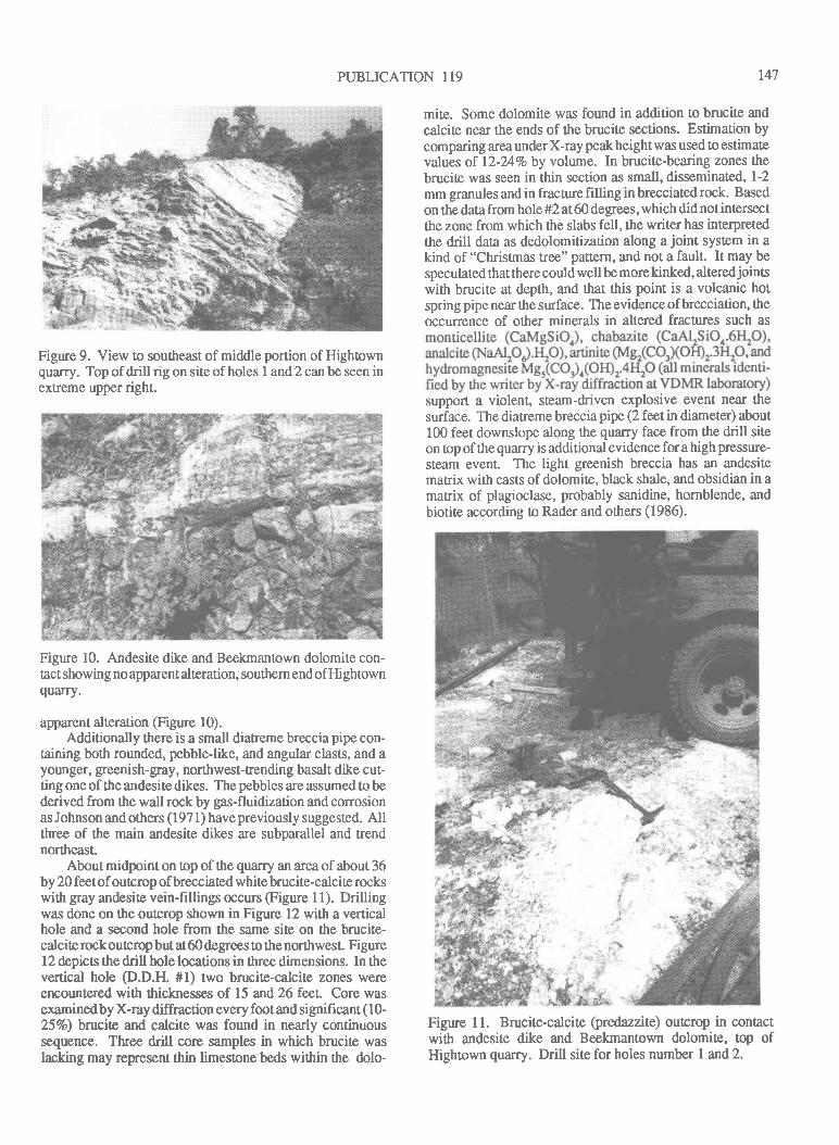
PUBLICATION 119 t47
Figure 9. View to southeast of middle portion of Hightownquarry. Top of drill rig on site of holes I and 2 can be seen inextreme upper right.
Figure 10. Andesite dike and Beekmantown dolomite con-tact showing no apparent alteration, southem end of Hightownquarry.
apparent alteration (Figure l0).Additionally there is a small diatreme breccia pipe con-
taining both rounded, pebble-like, and angular clasts, and ayounger, greenish- gray, northwest-trendin g basalt dike cut-ting one of the andesite dikes. The pebbles are assumed to bederived from the wall rock by gas-fluidization and corrosionas Johnson and others (197 1) have previously suggested. Allthree of the main andesite dikes are subparallel and trendnortheast.
About midpoint on top of the quarry an area of about 36by 20 feetof outcrop of brecciated whitebrucite-calcite rockswith gray andesite vein-fillings occurs (Figure 11). Drillingwas done on the outcrop shown in Figure 12 with a verticalhole and a second hole from the same site on the brucite-calciterockoutcrop but at 60 degrees to the northwesl Figure12 depics the drill hole locations in three dimensions. In thevertical hole @.D.H. #1) two brucite-calcite zones wereencounlered with thicknesses of 15 and 26 feet Core wasexamined by X-ray diffraction every foot and significant ( l0-25Vo) brucite and calcite was found in nearly continuoussequence. Three drill core samples in which brucite waslacking may repesent thin limestone beds within the dolo-
mite. Some dolomite was found in addition to brucite and
calcite near the ends of the brucite sections. Estimation bycomparing area under X-ray peak height was used to estimatevalues of l2-24%o by volume. In brucite-bearing zones thebrucite was seen in thin section as small, disseminated, 1-2
mm granules and in fracture frlling in brecciated rock. Based
on the data from hole #2 at 60 degrees, which did not intersectthe zone from which the slabs fell, the writer has interpretedthe drill data as dedolomitization along a joint syst€m in akind of "Christmas tree" pattern, and not a fault. It may bespeculated that there could well be more kinked, altered jointswith brucite at depth, and that this point is a volcanic hotspring pipe near the surface. The evidence of brecciation, theoccurrence of other minerals in altered fractures such as
support a violent, steam-driven explosive event near thesurface. The diatreme breccia pipe (2 feetn diameter) about100 feet downslope along the quarry face from the drill siteon top ofthe quarry is additional evidence for a high pressure-
steam event. The light greenish breccia has an andesitematrix with casts of dolomite, black shale, and obsidian in amatrix of plagioclase, probably sanidine, hornblende, andbiotite according to Rader and others (1986).
Figure 11. Brucite-calcite (gredazzite) outcrop in contactwith andesite dike and Beekmantown dolomite, top ofHightown quarry. Drill site for holes number I and 2.
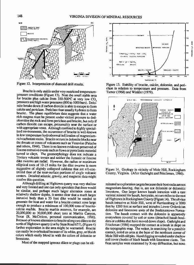
148
NW
----- mlomrt
I rc@urrrI
uETASTABIF BRUCTTI I rerrsreAre eenrctrst
c.Is(CO3)2 - C.CO3 + MsO + zCOz
DOLO{ITE CALCITE} P€RICLASE
uso+H2O-Mq(OHlz
Figure 12. Interpretation of diamond drill results.
Brucite is only stable under very restricted temperatue-pressure conditions (Figure l3). Note the small stable areafor brucite plus calcite from 350-500qC at very low CO,pressures and high water pressures (800 o 1000 bars). Dololmite breaks down if carbon dioxide is able to escape to formcalcite and periclase. Periclass than usrreily hydraies to formbrucite. The phase equilibnium data suggests that a waterrich-magma must be present under viobnl pressure to ded-olomitize the rock and form periclase and brucite, but only ifcarbon dioxide can escape, presumably near $re surfacs orwith appropriat€ vents. Although confined to highly special-ized environments, the occurence of brucite is well-knownin low temperanre hydrothermal infilfation of magnesium-rich carbonate rocks. Brucite occurs in dolomite blocks nearthe throats or cones of volcanoes such as Vesuvius @alacheand others, 1944). There is no lnown evidence preserved ofEocene extrusive events such as flows orpyroclastic materialtumed to clays. The geomorphology does not indicate aTertiary volcanic terrain and neither the Jurassic or Eocenedike swarms are radial. However, the radius or maximumelliptical axes of 10-15 miles for the dike swarms is moresuggestive of slightly collapsed calderas that are rift-con-trolled than of lhe near-surface portions of single volcaniccenters. Detailed seismic, gravity, and magnetic data mightresolve this question.
Alttrough drilling at Hightown quarry was very shallowand very limited and one can only speculate that there wouldbe similar, and perhaps much larger alteration zones atlelatively shallow depths, it seems clear that a much largerintrusive body than a 35 foot dike would be needed ogenerate the heat and water for a brucite con0act zone largeenough to produce a minimum of 100,000 tons of brucire-calcite marble. Brucite marble reserves, for example, are20,000,000 to 30,000,000 short tons at Marble Canyon,Texas @. McCreless, personal communication, 1990).Because of known alteration tobrucitealong two dikes to thenorth of Hightown quarry (cur by Stare Ro ad 637),(Figure 4)further exploration in the area might be warranted. Brucitecan easily be overlooked because ofits white, gray, or bluishcolors which easily blend in with the colors of dolomite orlimestone.
Most of the mapped igneous dikes or plugs can be eli-
o 1000300 35O aoo a50 50o 55O 600 650 ?OO 750 AOO
Figure 13. Sability of brucite, calcite, dolomite, and peri-clase in relation to tempera0re and pressure. Data fromTumer (1968) and Winkler (1979).
MOLE HILL ROCKINGHAM COUNTY VIRGINIA
to*u,.*""ot IBEEKTAITOWN FM
UPPER AIOMIODL€ IIMESTON€ I I
,r"a* ooao*'ru ffi
oo,o*,au ffiF'.!
FAULT Z
Rgure 14. Geology in vicinity of Mole Hill, RockinghamCounty, Virginia. (After Gathright and Frischman, 1986).
minated as exploration targets because their host rocks arc notmagnesium-bearing, that is, are not dolomite or dolomiticlimestone. One larger known basalt inrusion with a rarevarietal mineral for basalt, hercynite, occurs miles to the eastof Hightown in Rockingham County @gure 14). The olivinebasalt inrusive at Mole Hill, west of llanisonburg is 2000feet by 1200 feet at surface and intrudes Lower Ordoviciandolomite and limestone units of the Beekmantown Forma-tion. The basalt conlact wittr the dolomite is apparentlyeverywhere covered by soil or scree (detached basalt boul-ders or cobbles that have moved down slope). Gattright andFrischman (1986) mapped the contact at a break in slope onthe topographic map. The writer, in searching for a possiblecontact" not€d an area at the base of the northeast corner ofMole Hill with old pits. Hand digging revealed under shallowsoil cover chunks of black basalt with limestone clasts. Tenfloat samples were examined by X-ray diffraction, but none
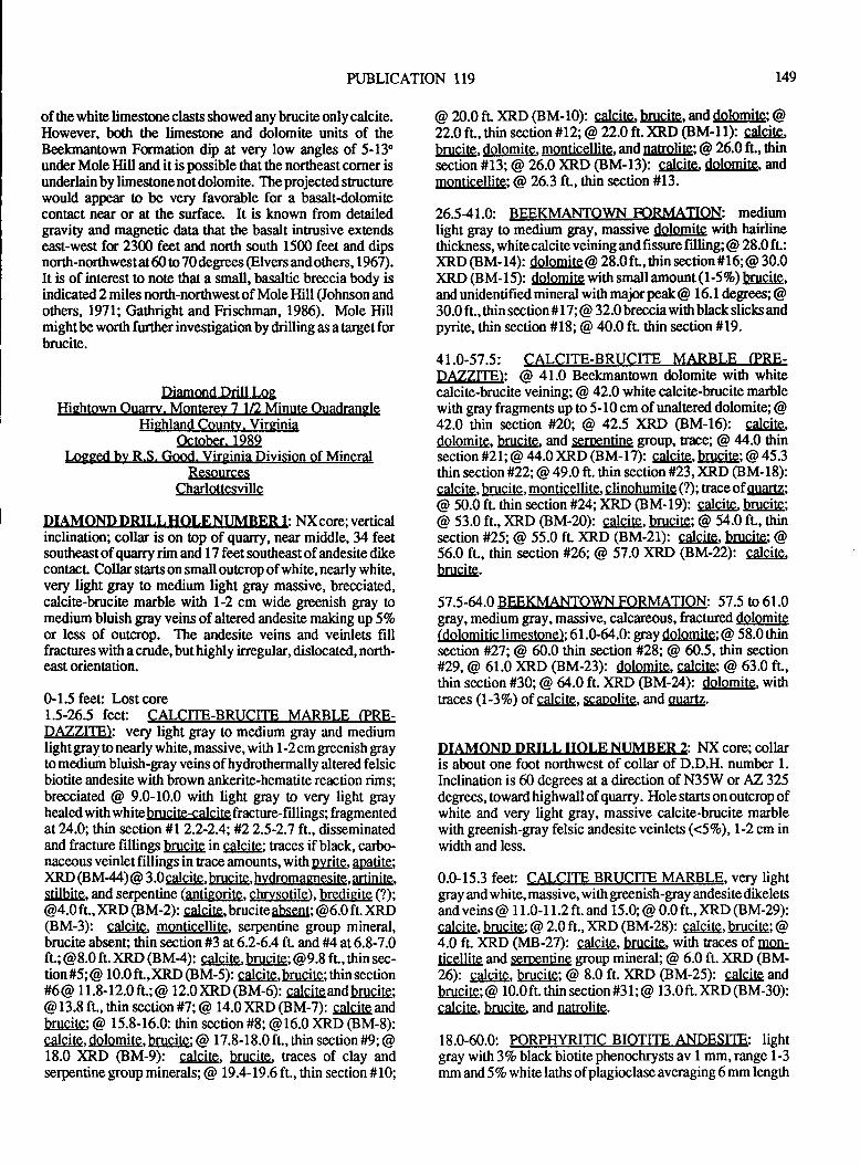
PUBLICATION 119 r49
of the white limestone class showed any brucite only calcite.However, both the limestone and dolomite units of theBeekmantown Formation dip at very low angles of 5-13"under Mole Hill and it is possible that the northeast corner isunderlain by limestone not dolomite. The projected structurewould appear to be very favorable for a basalt-dolomitecontact near or at the surface. It is known from detailedgravity and magnetic data ttnt the basalt intmsive extendseast-west for 2300 feet and north south 1500 feet and dipsnorth-nonthwestat60 o 70 degrees @lvers andothers, 1967).It is of interest to note that a small, basaltic breccia body isindicated 2 miles north-northwest of Mole Hill (Johnson andothers, l97l; Gathright and Frischman, 1986). Mole Hillmight be worth further investigation by drilling as a target forbrucite.
Diamond Drill LosHightown Ouarry. Montere)r 7 1/2 Minute Ouadransle
Highland Countv. VireiniaOctober. 1989
Logged by R.S. Good. Virsinia Division of MineralResources
Charlottesville
DIAMOND DRILLHOLENUMBER 1: NXcore; verticalinclination; collar is on top of quarry, near middle, 34 feetsoutheast ofquarry rim and 17 feet southeast ofandesite dikecontacL Collar starts on small outcrop of white, nearly white,very light gray to medium light gray massive, brecciated,calcite-brucite marble with 1-2 cm wide greenish gray tomedium bluish gray veins of altered andesite making up 5Vo
or less of outcrop. The andesite veins and veinlers fillfractures with a crude, but highly inegular, dislocated, north-east orientation.
0-1.5 feeu Lostcore1.5-26.5 feet: CALCITE-BRUCITE MARBLE (PRE-DAZZIIBI: very light glay to medium gray and mediumlight gray to nearly white, massive, with 1-2 cm greenish grayto medium bluish-gray veins of hydrothermally altered felsicbiotite andesite with brown ankerite-hematite reaction rims;brecciated @ 9.0-10.0 with light gray to very light grayhealed with whitebnrcite+alcite fracture-fillings; fragmentedat 24.0; thin section #l 2.2-2.4: #2 2.5-2.7 ft., disseminatedand fracture fillings brucite in calcite; traces if black, carbo-naceous veinlet fi llings in race amounts, with py!19, aoati te;)(RD (8M44) @ 3.0 calcite, brucite, hydromagnesite, Q4!!d&,rtllbitg, and serpentine (a$igAr!!e, @!etri!g), bredigite (?);
@4.0 ft., XRD @M-2) : galgilg, brucite absent; @ 6.0 fL XRD(BM-3): calcite. monticellite, serpentine group mineral,brucite absent; thin section #3 at6.2-6.4 ft. and #4 at6.8-7.0fU @8.0 ft. )(RD (BM4): g4!sig, brucite; @9.8 fr, ilrin sec-tion #5; @ 1 0.0 fL, XRD (BM-5): calcire, brucire; rhin secrion# 6 @ lI.8-I2.0 ft . ; @ I 2.0 )(RD (BM-6) : calcite and bruci te;
@ 13.8 ft., thin section #7; @ 14.0 )(RD (BM-7): calcite andbrucite; @ 15.8-16.0: thin section #8; @ 16.0 XRD (BM-8):calcite, dolomite, brucite; @ 17.8-18.0 ft., thin section #9; @18.0 )(RD @M-9): gdgilg, brucite, Eaces of clay andserpentine group minerals:@ I9.a-D.6 ft., ttrin section #10;
@ n.0 fr )(RD (BM-10): cdc!!g,b$ciE, anddolomite; @22.0 fL,thin section #12; @ 22.0 ft )(RD (BM-l l): Calcilg,brucite, dolomite, !M!!t!gd!!Ig, and natrolite; @ 26.0 ft., thinsection #13; @ 26.0 )(RD (BM-13): calcite. dolomite, andmonticellite; @ 26.3 ft., thin section #13.
26541.0: BEEKMANTOWN FORMATION: mediumlight gray to medium gray, massive dolomite with hairlinethickness, whitecalciteveining and fissure filling; @ 28.0 fr:)(RD (BM- 14): da!@ilg @ 28.0 ft., thin section # 1 6; @ 30.0)(RD (BM-15): dolomite with small amount (l-5%) brucite,and unidentified mineral with majorpeak@ 16.1 degrees; @30.0 ft., thin section # 1 7; @ 32.0 breccia with black slicts andpynle, thin section *18; @ 40.0 ft. thin section #19.
41.0-57.5: CALCITE-BRUCITE MARBLE (PRE-DATZITE\: @ 41.0 Beekmantown dolomite with whitecalcite-brucite veining; @ 42.0 white calcite-brucite marblewith gray fragments up to 5-10 cm of unaltered dolomite; @42.0 thin section #20; @ 42.5 XRD (BM-16): calcite.dolomite, brucite. and serpentine group, trace; @ 44.0 thinsection #21; @ 44.0 )(RD (BM-17): calcite, bgtgilE; @ 45.3thin section#22;@ 49.0 ft. thin section#23,XRD (BM-18):calcite, btrs:ils, !!!e!!tic9!!it9, s!i.Esh@!Ig (?); trace of quartz;
@ 50.0 fr thin section #Z; XRD (BM-19): calcite. brucite;
@ 53.0 ft., XRD @M-20): gdg!.!q, brucite; @ 54.0 ft., thinsection *25; @ 55.0 ft )(RD (BM-21): calcite, brucite; @56.0 ft., thin section #26; @ 57.0 XRD (BM-22): calcite.brucite.
57.5-64.0 BEEKMANTOWN FORMATION: 57.5 to 61.0gray, medium gray, massive, calcareous, fractured dolomite(dolomitic limestone);61.G64.0: gray dolomite; @ 58.0 thinsection #27; @ 60.0 thin section *28; @ 60.5, thin section#29,@ 61.0 XRD (BM-23): dolomite, calcite: @ 63.0 ft.,thin section *30; @ &.0 ft.)RD (BM-24): dslsitrq, withtraces (l-37o) of calcite, lCaDelilg, and quartz.
DIAMOND DRILL HOLE NUMBER 2: NX core; collaris about one foot northwest of collar of D.D.H. number 1.
Inclination is 60 degrees at a direction of N35W or A2325degrees, toward highwall of quarry. Hole starts on outcrop ofwhite and very light gray, massive calcite-brucite marblewi0r greenish-gray felsic andesite veinlets (<57o), l-2 cm inwidth and less.
0.0-15.3 feeu CALCITE BRUCITE MARBLE, very lightgray and white, massive, with greenish-gray andesite dikeletsand veins @ I 1.0- 1 1.2 ft. and 15.0; @ 0.0 ft., )G.D (BM-29):calcite, brucite; @ 2.0 fr., xRD (BM-28): calcite, brucite; @4.0 ft. )(RD (MB-27): gdg!!e,, brucite. with Eaces of lqEticellite and serpentine group mineral; @ 6.0 ft. )(RD (BM-26): galCllg, brucite: @ 8.0 ft. )(RD (BM-25): calcite andbrucite; @ 10.0 ft. thin section #3 I ; @ I 3.0 ft. XRD (BM-30):gdcj.!g, brucib, and narolite.
18.0-60.0: PORPHYRITIC BIOTITE ANDESITE: lightgray with 37o black biotite phenochrysts av 1 mm, range 1-3
mm and 57o whitelaths ofplagioclaseaveraging6mm length
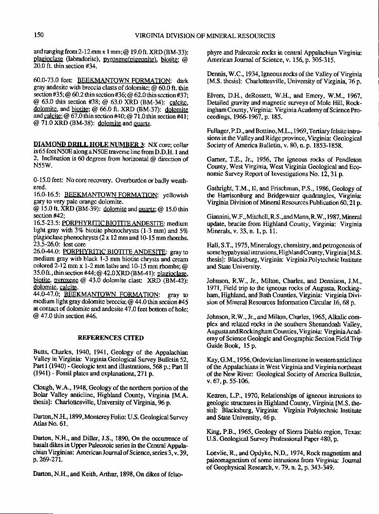
150 VIRGINIA DIVISION OF MINERAL RESOURCES
and ranging from 2-12 mm x 1 mm ; @ 1 9.0 fr. )(RD (BM-3 3):olaEioclase (labradorite), oyroxene(niqeonite). biotite; @20.0 ft. ttrin section #34-
60.0-73.0 feec BEEKMANTOWN FORMATION: dartgray andesite with breccia clasts of dolomite; @ 60.0 ft. thinsection #35; @ 60.2 thin secti on#36;@ 62.0 thin section #37;@ 63.0 thin section #38; @ 63.0 )(RD (BM-34): catcite.de!@itrg, and biotite; @ 66.0 ft. )RD (BM-37): dolomireand calcite; @ 67.0 thin section #40; @ 71.0 thin section #4 I :@ 71.0 )(RD (BM-38): dolomite and Erartz.
DIAMOND DRILL HOLE NUMBER 3: NX core; collaris 65 feet N50E along a N50E traverse line from D.D.H. 1 and2. Inclination is 60 degrees from horizontal @ direction ofN55W.
0-15.0 feet No corerecovery. Overburden orbadly weath-ered.16.0-16.5: BEEKMANTOWN FORMATION: yellowishgary to very pale orange dolomite.@ 15.0 ft. )(RD (BM-39): dolomite and quartz; @ 15.0 thinsection #42;16.5-23.5: PORPHYRITIC BIOTITE ANDESITE: mediumlight gray with 3Vo biotite phenochrysts (1-3 mm) and 5Toplagioclasephenochryss (2 x 12 mm and 10-15 mm rhombs.23.5-2-6.0: lost core26.044.0: PORPHYRITIC BIOTITE ANDESITE: gray tomedium gray with black 1-3 mm biotite chrysts and creamcolored 2-l2mm x 1-2 mm laths and 10-15 mm rhombs; @35.0 fr, ilrin sec uon #44; @ 42.0 XRD (B M4 1) : plagiOghsg,biel&, LyrcISUe @ 43.0 dolomite clasr XRD (BM42):dolomite, calcite.44.047.0: BEEKMANTOWN FORMATION: gray romedium light gray dolomite brecciq @ 44.0 thin section tt45at contact of dolomite and andesite 47.0 feet bottom of hole:@ 47.0 thin section #46.
REFERENCES CITED
Buss, Charles, 1940, 1941, Geology of the AppalachianValley in Virginia: Virginia Geological Survey Bulletin 52,Part I (1940) - Geologic text and illusrnations, 5tr p.; Part II(1941) - Fossil plates and explanations ,271p.
Clough, W.A., 1948, Geology of the northern portion of theBolar Valley anticline, Highland County, Virginia tM.A.tttesisl: Charlouesville, University of Virginia, *i p.
Darton, N.II., 1899, Monterey Folio: U.S. Geological SurveyAtlasNo.6l.
Darton, N.H., and Diller, J.S., 1890, On the occurrence ofbasalt dikes in Upper Paleozoic series in the Cenral Appala-chian Virginias: American Joumal of Science, series 3, v. 39,p.?69-27r.
Dafion, N.H., and Keith, Arthur, 1898, On dikes of felso-
phyre and Paleozoic rocks in central Appalachian Virginia:American Joumal of Science, v. 156, p. 305-315.
Dennis, W.C.,l934,Igneous rocks of the Valley of Virginia[M.S. thesis]: Charlottesville, University of Virginia, 76 p.
Elvers, D.H., deRossett, W.H., and Emery, W.M., 1967,Detailed gravity and magnetic surveys of Mole Hill, Rock-ingham County, Virginia: Virginia Academy of Science Pro-ceedings, 196f,-1967, p. 185.
Fullager, P.D., and Bottino, M.L., 1969,Tertiary felsite intru-sions in the Valley and Ridge province, Virginia: GeologicalSociety of America Bulletin, v. 80, n. p. 1853-1858.
Gamer, T.E., Jr., 1956, The igneous rocks of PendletonCounty, West Virginia, West Virginia Geological and Eco-nomic Sunrey Report of Investigations No. 12,31p.
Gathright, T.M., II, and Frischman, P.S., 1986, Geology ofthe llarrisonburg and Bridgewater quadrangles, Virginia:Virginia Division of Mineral Resources Publication 60, 21 p.
Giannini, W.F., Mitchell, R.S., andl\[ann, R.W., 1987, Mineralupdate, brucite from Highland County, Virginia: VirginiaMinerals, v. 33, n. 1, p. 11.
Ilall, S.T., 1975, Mineralogy, chemistry, and petrogenesis ofsome hypabyssal intrusions, HighlandCounty, Virginia [M.S.thesisl : Blacksburg, Virginia: Virginia Polytechnic Instituteand Sate University.
Johnson, R.W., Jr., Milton, Charles, and Dennison, J.M.,1971, Field nip to the igneous rocks of Augusta, Rocking-ham, Highland, and Bath Counties, Virginia: Virginia Divi-sion of Mineral Resources Information Circular 16,68 p.
Johnson, R.W., Jr., and Milton, Charles, 1965, Alkalic com-plex and related rocks in the southem Shenandoah Valley,AugustaandRockingham Counties, Vfuginia: VirginiaAcad-emy of Science Geologic and Geographic Section Field TripGuide Book, 15 p.
Kay, G.M., 1956, Ordovician limestone in western anticlinesof the Appalachians in West Virginia and Virginia northeastof the New River: Geological Society of America Bulletin,v.67,p.55-106.
Keffren, L.P., 1970, Relationships of igneous intrusions togeologrc structures in Highland County, Virginia [M.S. the-sisl: Blacksburg, Virginia Virginia Polytechnic krstifirteand State University,46 p.
King, P.B., 1965, Geology of Sierra Diablo region, Texas:U.S. Geological Survey hofessional Paper 480, p.
Loevlie, R., and Opdyke, N.D., 1974, Rock magnetism andpaleomagnetism of some in8usions from Virginia Journalof Geophysical Research, v.79, n. 2,p.343-349.
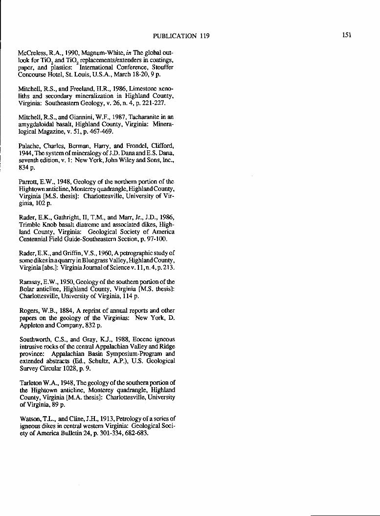
PUBLICATION 119
McCreless, R.A., 1990, Magnum-White, in The global out-lmk for TiQ and TiQ replacements/extenders in coatings,paper, and plastics: International Conference, StoufferConcourse Hotel, St.Iouis, U.S.A., lvlarch 18-20, 9 p.
Mitchell, R.S., and Freeland, H.R., 1986, Limestone xeno-liths and secondary mineralization in Highland County,Virginia: Southeastern Geology, v. 26, n. 4, p. 221-227 .
Mirchell, R.S., and Giannini, W.F., 1987, Tacharanite in anamygdaloidal basalt, Highland County, Virginia: Minera-logical Magazine, v. 51, p. 467-469.
Palache, Charles, Bsrman, Harry, and Frondel, Clifford,1944,Thesystemof mineralogy of J.D. DanaandE.S. Dana,seventh edition, v. 1 : New York, John Wiley and Sons, Inc.,834 p.
Parrott" 8.W., 1948, Geology of the northern portion of theHightown anticline, Monterey quadrangle, Highland County,Virginia [M.S. thesis]: Charlottesville, University of Vir-ginia, 102 p.
Rader, 8.K., Gathright, II, T.M., and Marr, Jr., J.D., 1985,Trimble Knob basalt diaueme and associated dikes, High-land County, Virginia: Geological Society of AmericaCentennial Field Guide-Southeastern Section, p. 97- I 00.
Rader, E.K., andGriffin, V.S., 1960, Aperographic study ofsome dikes in aquarry in Bluegass Valley, HighlandCounty,Virginia [abs.] : Virginia Journal of Science v. 1 1, n. 4, p. 2 1 3.
Ramsay, 8.W., 1 950, Geology of the soutrern portion of theBolar anticline, Highland County, Virginia [M.S. thesis]:Charlottesville, University of Virginia, 114 p.
Rogers, W.B., 1884, A reprint of annual reports and otherpapers on the geology of the Virginias: New York, D.Apploton and Company, 832 p.
Southworth, C.S., and Gray, KJ., 1988, Eocene igneousintrusive rocks of the central Appalachian Valley and Ridgeprovince: Appalachian Basin Symposium-Program andextended abstracts @d., Schultz, A.P.), U.S. GeologicalSurvey Circular 1028, p. 9.
Tarleton W.A., 1948, The geology of the southern portion ofthe Hightown anticline, Monterey quadrangle, HighlandCounty, Virginia [M.A. thesis]: Charlottesville, Universityof Virginia,89 p.
Watson, TI., and Cline, J.H., 19 I 3, Petrology of a series ofigneous dikes in central western Virginia: Geological Soci-ety of America Bulletin 24, p. 301-334, 682-683.
151

152 VIRGINIA DTVISION OF MINERAL RESOI.JRCES
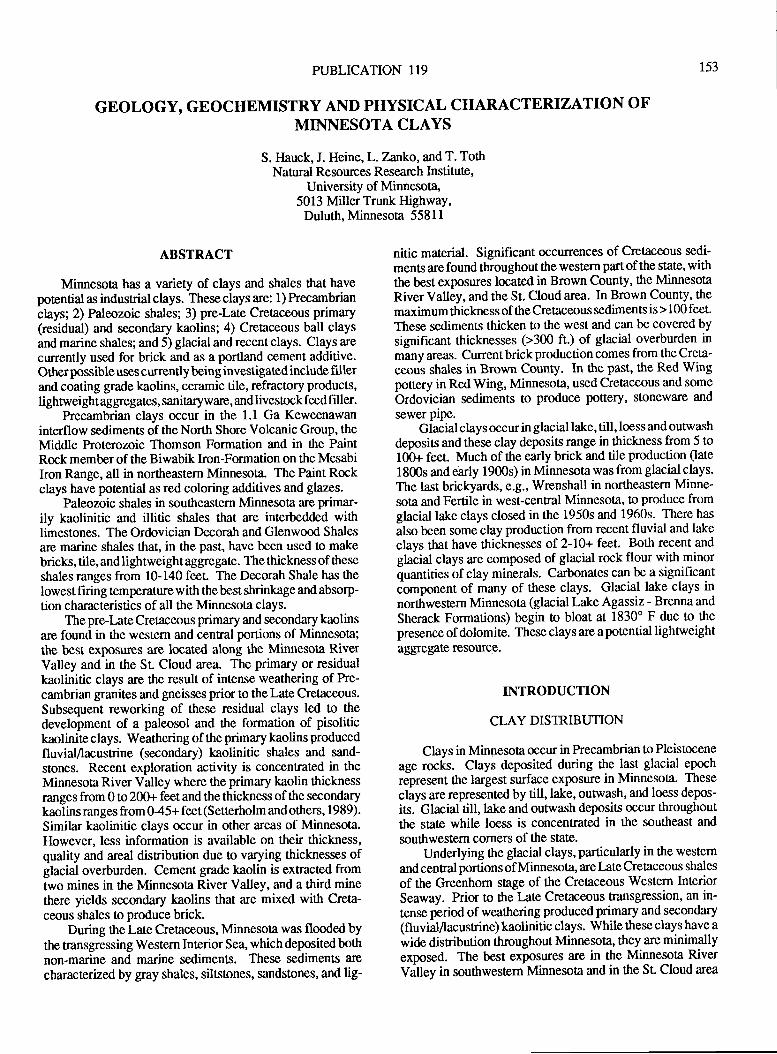
PUBLICATION 119
GEOLOGY, GEOCHEMISTRY AND PHYSICAL CHARACTERIZATION OFMINNESOTA CLAYS
S. Ilauck, J. Heine, L.Zanko, and T. TothNatural Resources Research Institute,
University of Minnesota,5013 Miller Trunk HighwaY,
Duluth, Minnesota 5581 I
153
ABSTRACT
Minnesota has a variety of clays and shales that havepotential as industrial clays. These clays are: 1) Precambrianclays; 2) Paleozoic shales; 3) pre-Late Cretaceous primary(residual) and secondary kaolins; 4) Cretaceous ball claysand marine shales; and 5) glacial and recent clays. Clays are
currently used for brick and as a portland cement additive.Other possible uses currently being investigated include frllerand coating grade kaolins, ceramic tile, refractory products,lighnveightaggregates, sanitaryware, and livestock feed filler.
Precambrian clays occur in the 1.1 Ga Keweenawaninterflow sediments of the North Shore Volcanic Group, theMiddle Proterozoic Thomson Formation and in the PaintRock member of the Biwabik Iron-Formation on the Mesabihon Range, all in northeastern Minneso0a. The Paint Rockclays have potential as red coloring additives and glazes.
Paleozoic shales in southeastern Minnesota are primar-ily kaolinitic and illitic shales that are interbedded withlimestones. The Ordovician Decorah and Glenwood Shales
are marine shales that, in the past, have been used to make
bricks, tile, and lightweight aggregate. The thickness of these
shales ranges from 10-140 feet. The Decorah Shale has thelowest firing temperaturewith thebest shrinkage and absorp-tion characteristics of all the Minnesota clays.
The pre-Late Cretaceous primary and secondary kaolinsare found in the western and cenEal portions of Minnesota;the best exposwes are located along the Minnesota RiverValley and in the Sr Cloud area. The primary or residualkaolinitic clays are the result of intense weathering of he-cambrian granites and gneisses prior to tlte Late Cretaceous.
Subsequent reworking of these residual clays led to thedevelopment of a paleosol and the formation of pisolitickaolinite clays. Weathering of the primary kaolins producedfluviaVlacustrine (secondary) kaolinitic shales and sand-
stones. Recent exploration activity is concentrated in the
Minnesota River Valley where the primary kaolin thicknessranges from 0 to 20Gr feet and the thickness of the secondarykaolins ranges from 045+ feet (Setterholm and others, 1989).
Similar kaolinitic clays occur in other areas of Minnesota.However, less information is available on their thickness,quality and areal disribution due to varying thicknesses ofglacial overburden. Cement grade kaolin is extracted fromtwo mines in the Minnesota River Valley, and a third minethere yields secondary kaolins that are mixed with Creta-
ceous shales to produce brick.During the Late Cretaceous, Minnesota was flooded by
the transgressing Western Interior Sea, which depositedbothnon-marine and marine sediments. These sediments arc
characterized by gay shales, siltstones, sandstones, and lig-
nitic material. Significant occurences of Cretaceous sedi'ments arefound throughout the western partof the state, withthe best exposures located in Brown County, the Minnesota
River Valley, and the St. Cloud area. In Brown County, the
maximum thickness of the Cretaceous sediments is > 100 feet.
These sediments thicken to the west and can be covered bysignificant thicknesses (>300 ft.) of glacial overburden in
many arqts. Current brick production comes from the Creta-
ceous shales in Brown County. In the past, the Red Wingpottery in Red Wing, Minnesota, used Cretaceous and some
Ordovician sediments to produce pottery, stoneware and
sewer pipe.Glacial clays occur in glacial lake, till, loess and outwash
deposis and these clay deposits range in thickness from 5 tot0O+ feet. Much of the early brick and tile production (late
1800s and early 1900s) in Minnesota was from glacial clays.
The last brickyards, e.g., Wrenshall in northeastern Minne-sota and Fertile in west-central Minnesota, to produce fromglacial lake clays closed in the 1950s and 1960s. There has
also been some clay production from recent fluvial and lakeclays that have thicknesses of2-10+ feet. Both recent and
glacial clays are composed of glacial rock flour with minorquantities of clay minerals. Carbonates can be a significantComponent of many of these clays. Glacial lake clays innorttrwestern Minneso[a (glacial Lake Agassiz - Brenna and
Sherack Formations) begin to bloat at 1830' F due to the
presence of dolomite. These clays are apotential lightweightaggregats resource.
INTRODUCTION
CLAY DISTRIBUTION
Clays in Minnesota occur in Precambrian to Pleistocene
age rocks. Clays deposited during the last glacial epoch
represent the largest surface exposue in Minnesota. These
clays are represented by till, lake, oug'va.sh, and loess depos-
its. Glacial till, lake and outwash deposits occur throughout
the state while loess is concentrated in the southeast and
southwestem corners of the state.
Underlying the glacial clays, particularly in the westem
and cenral portions of Minnesota, are Late Crelaceous shales
of the Greenhom stage of the Cretaceous Western InteriorSeaway. Prior to the Late Cretaceous transgression, an in-tense period of weathering produced primary and secondary
(fluviallacustrine) kaolinitic clays. While these clays have a
wide disribution throughout Minnesota, they are minimallyexposed. The best exposures are in the Minnesota RiverValley in southwestern Minnesota and in the Sr Cloud area
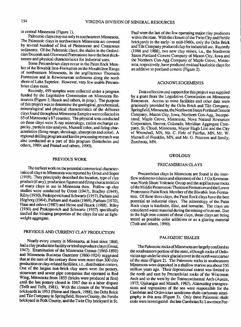
154 VIRGINIA DIVISION OF MINERAL RESOURCES
Paul were the last of the few operating major clay producerswithin the state. With ttre closure of the Twin City and Fertilebrickyards in the early- to mid-1960s, only the Ochs Brickand Tile Company produced clay for industrial use. Recently(1986 and 1988), nvo new clay mines, i.e., the NorthwestStates Portland Cement Company of Mason City, Iowa andthe Northern Con-Agg Company of Maple Grove, Minne-sota, respectively, have produced residual kaolinitic clays foran additive to portland cement (Figure 2).
ACKNOWLEDGEMENTS
Data collection and support for this project was suppliedby a grant from the I-egislative Commission on MinnesotaResources. Access to mine facilities and other data weregaciously provided by the Ochs Brick and Tile Company,Springfield, Minnesota, theNorthwest States portland CementCompany, Mason City, Iowa, Northern Con-Agg, Incorpo-rated, Maple Grove, Minnesota, Nova Natural ResourcesCorporation, Denver, Colorado, Meridian Aggregate Com-pany, St. Cloud, Minnesota, Mayor Hugh Line and the Cityof Wrenshall, MN, Mr. C. Firle of Fairfax, MN, Mr. W.Munsell of Franktn, MN, and Mr. G. Peterson and family,Zumbrota, MN.
GEOLOGY
PRECAMBRIANCLAYS
Precambrian clays in Minnesota are found in the inter-fl ow sediments (shales and siltstones) of the 1 . I Ga Keweena-wan North Shore Volcanic Group and the argillaceous rocksof the Middle Proterozoic Thomson Formation and the IowerProterozoic Paint Rock Member of the Biwabik hon-Forma-tion. Of these three clays, the Paint Rock clays have the bestpotential as indusrial clays. The mineralogy of the PaintRock clays is kaolinite, illite, and hematite. The clays areconsidered waste material during the mining of iron ore. Dueto the high iron content of these clays, these clays are beinglssted as possible color additives or as a glazng material(Toth and others, 1990).
PALEOZOIC SHALES
The Paleozoic rccks of Minnesota are largely confined tothe southeastern portion ofthe state, although rocks ofOrdo-vician age underlie thick glacial cover in the nortlwest comerof the state (Figure 2). The Paleozoic rocks in southeastemMinnesota weredeposited in a shallow marine seaabout 550million ye:trs ago. Their depositional extent was limited tothe north and east by Precambrian rocks of the WisconsinArch and to the west by the Transcontinental Arch (Austin,1972; Ojatangas and lvlatsch, 1982). Alternating mnsgres-sions and regressions of the sea were responsible for theCambrian and Ordovician sandstone-shale-carbonate strati-graphy in this area (Figure 3). Only three Paleozoic shaleunits were investigated: the late Cambrian S L Lawrence For-
in central Minnesota (Figure 1).Paleozoic clays crop out only in southeastem Minnesota.
The Paleozoic clays in northwestern Minnesota are coveredby several hundred of feet of pleistocene and Cretaceoussediments. Of the Paleozoic clays, the shales in the O,rdovi-cian Decorah and GlenwoodFormations have thebestthick-nesses and physical characteristics for industrial uses.
Some Precambrian clays occur in the paint Rock Mem-berof the Biwabik lron-Formation on the Mesabi hon Rangeof northeastern Minnesota, in the argiltaceous ThomdnFormation and in Keweenawan sediments along the northshore of Lake Superior. However, very few usable precam-brian clays exist.
Recently,499 samples were collected under a programfunded by the Legislative Commission on Minneiota Re-sources @igure 1; Ilauck and others, in prep.). The purposeof this project was Eo determine *re geological, geochemical,mineralogical and physical characleristics of the differentclays found throughout Minnesota Samples were collected in65 of Minnesota's 87 counties. The physical tests conductedon these clays were X-ray mineralogy, cation exchange ca-pacity, particle size analysis, Munsellcolor, and firing char-acteristics (firing range, shrinkage, absorption and colo|. Aregional drilling progam and kaolin processing research wasalso conducted as a part of this prograrn (Setterholm andothers, 1989; and Prasad and others, 1990).
PREVIOUS WORK
The earliestworkon the potential commerical character-
iqti^gs-gf c9fs in Minnesota was reportedby Grout and Soper(1919). Tlrey pnncipally described the locar,ion, type of ciayproduct (ifany), production figures and firing characteristicsof many clays in use in Minnesota then. Foilow up claystudies were conducted by Grout (1947), Bradley liXl),Riley ( I 950), Prokopovich and Schwartz ( I 957), parham andHogberg (1964), Parham and Austin (1969), parham (1970),
l!3g and gthers (1987) and Heine and }Iauck (1988), Riley(1 95O)- and Prokopovich and Schwartz ( 1957) specifrcallystulied the bloating properties of *re clays for usi as lighi-weight aggregate.
PREVIOUS AND CURRENT CLAY PRODUCTION
Nearly every county in Minnesota, at least since 1g60,had a clay production facility or ried to produce clays (Grout,1947). Examinuion of the Minnesora Census (lti60-1g90)and Minnesota Business Gaznttenr (1860-1924) suggestedthat at the turn of the century there were more than 300 clayproduction u clay-related facilities, i.e., distribution centers.One of the largest non-brick clay users were the potbry,storewarc and sewer pipe companies that opemted in RedWing, Minnesoa from 1855 (bricks were produced at firsQultif the last pottery closed in 1962 due to a labo dispure(Tefft and Tefft, l98l). With ttre closure of the Wrenshallbrickyards in 1953 (Heine and llauck, 1988), the Ochs Brickand Tile Company in Springfield, Brown County, the Fertilebrickyard in Polk County, and theTwin City brickyard in St.
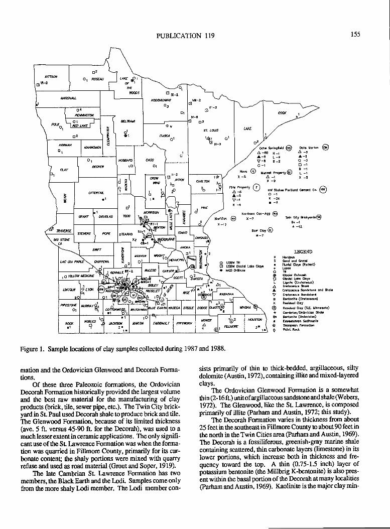
nnsoil
DvFr
tr2
O1 r$9{r
L-'."}*;ItE \r-'vel
6 u-tk&cilcilN6
tr1
lrA*A -
\,^-vn-z v \\
- vil-3utv-!
3oJ
9r- aal/s
141 olv lt-5
uA8sr141 I noors
I.ME
^2r/k
A.t-
M sprhsfDH @-to H -lf L-eE E-2
Ochr lDrtona-5a-ao-t
o{/{tll{li/6fa,Vn
I*lHIE'tslill
dLtPAU
A6rg2
N&t|*ltrt
HAIt{O#n
cAssIXJPAffi
Itr
(
o,ECXfRI o^,
trl- utnll
9tr
F
rcw@ unrcfl Pep*] @a-r L-lx-5
offEatAL
r'!
aTT
cFor,ile
rbtl
cARtTtN
bvlaT
Fkrc Pporrv frl' \--l Nw slot.r Ptrilffd c.mhi Ca
i-l o-1v-r x -21
a-zr-+s PNE -/
./ ud*2,t
o'
lt ttOr
'8 rt< |
t; I
ti t-tl
I\p"l&ANf
1
DdLld-AS'gcl
FFisol I
J
4 n.",\ "" "r*,\o.
*@ X-z - Twh (:itY IE-1* -12
8or cb, (9)*-7
I.ECEND
Itcttivs NPE---:5\E**s?E^/ws \jDF- l' ivn t
1l
swf \_>k,*,-- / \tr|
LAC C
-\ !! vffi
^l"r-fit) =
\*l w '-l r€l{,u*\F
kffilc {I A l. o usaM Trl
I S 1' I usSM clockl Lok. clqcI a MG tktlhoL
"orr-)'-J.-- at\i:'"11-r^\
I+oOIL4A
Sond @d &d.lfkrbl ools (R.ent)LCaatT'{clocid Oltsdh€losi.l Ld@ CLrtLiinitr (Cr.toc!a5)Cratdilt s}rdaCrat@aaa Sondrlona
LA^/ll,fR )\_,/st
r i\8alowt&tow I lea*ltef,rr-l
t! r ttrl.L r-ildrfr
ugINE-I
wcqt .1(1
o tYatq9A[EY l"f
'&' fldol
rrilr4aEr14 rtrl
aptsralcQt
t*t*^rd,."t
p (9o. sY -#?;ILUE EARI' 6#C/ s'Ea-€ aO,6E
1' a1fMSTEJDtr
tt* X R.rtu Oattrlor,r \ @ Rtidd oor (rE, r
i Combn'm&ovic'M*P*
atffiRt
d:tAro4w
R@<t1
,*rr" tlg'
a1
AA@Nz.
1r
I
HRW ,^rno, | ,oro. rcWA b,
FATRE
ltqJsTov
2,)t K?i*nrun SadFn6ls* lhwso fmltis0 Ps'ht i€k
PUBLICATION 119
Figure 1. Sample locations of clay samples collected during 1987 and 1988.
mation and the Ordovician Glenwood and Decorah Forma-tions.
Of the,se three Paleozoic formations, the OrdovicianDecorah Formation hislorically provided the largest volumeand ttre best raw material for the manufacturing of clayproducts (brick, tile, sewer pipe, etc.). The Twin City brick-yard in St. Paul used Decorah shale to produce brick and tile.The Glenwmd Formation, because of its limited thickness(ave. 5 fL versus 45-90 fr for the Decorah), was used to amuch lesser extent in ceramic applications. The only signifi-cant use of the St Lawrence Formation was when the forma-don was quanied in Fillmore County, primarily for its car-bonate confonq tre shaly portions were mixed with quarryrefuse and used as road material (Grout and Soper, 1919).
The late Cambrian St lawrence Formation has npomembrs, the Black Earth and the Lodi. Samples come onlyfrom the more shaly lodi member. The Lodi member con-
sists primarily of thin to thick-bedded, argillaceous, siltydolomite (Austin, 1972), containing illite and mixed-layeredclays.
The Ordovician Glenwood Formation is a somewhat
ttrin (2- 16 fr) unitof argillaceous sandstone and shale (Webers,
1972). The Glenwood,like the St.lawrence, is composedprimarily of illite @arham and Austin, 1972; tltis study).
The Decorah Formation varies in thiclness from about25 feet in the southeast in Fillmore County to about 90 feet inthe north in theTwin Cities area (Parham and Austin, 1969).
The Decorah is a fossiliferous, grcenish-gray marine shale
containing scattered, thin carbonate layers (limestone) in itslower portions, which increase both in thickness and fre-quency toward the top. A ttrin (0.75-1.5 inci) layer ofpotassium bentonite (the Millbrig K-benonite) is also pres-
ent within the basal portion of the Decorah at many localities
@arham and Austin, 1969). Kaolinite is the major clay min-
155
(0M/
q9
Brickprdr@
md Shol.
Miu.rotq)r Shol.
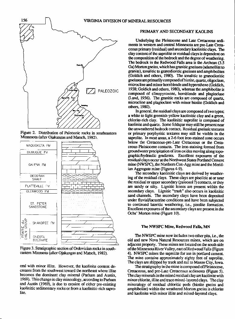
VIRGINIA DIVISION OF MINERAL RESOURCES
V- earcozotc
Figure 2. Distribution of Paleozoic rocks in southeasternMinnesoa (after Oiakangas and Matsch. 1982).
I./AQUOKETA FM
DUBUQUE FIil
GALENA Ffvl
DECORAHSHALE
PLATTIVILLE FM
GLENWOOD FM
ST. PETERSANDSTONE
L!our6t<=&!9
SHAKOPEE FM
ONEOTADOLOMITE
Figure 3. Snatigraphic section of Ordovician rocks in south-eastern Minnsota (after Ojakangas and lvlatsch, 1982).
eral with minor illite. However, the kaolinite content de-creases from the southwest toward the northeast where illitebecomes the dominant clay mineral @arham and Austin,1969). This change in clay mineralogy, according to parhamand Austin (1969), is due to erosion of either pre-existingkaolinitic sedimentary rocks or from a kaolinitic-rich sapro-lite.
PRIMARY AND SECONDARY KAOLINS
Underlying the Pleistocene and Late Cretaceous sedi-ments in western and central Mnnesota are pre-Iate crca-ceous primary (residual) and secondary kaolinitic clays. Theclay content of the saprolite or residual clays is dependent onthe composition of thebedrock and the degree of weathering.The bedrock in fte Redwmd Falls area is the Archean (3.5Ga) Moron gneiss, which has granitic gneisses (adamellite togranite), onalitic o granodioritic gneisses and amphibolites(Goldich and others, 1980). The tonalitic to granodioriticgneisses are pimarily composed of biotite, quartz, oligoclase,microcline and minor hornblende and hypenthene (Goldich,1938; Goldich and others, 1980), whereas 0re amphibotite iscomposed of clinopyroxene, hornblende and plagioclase(Lund, 1956). The granitic raks are composed of quartz,microcline ard plagioclase with minor biotite (Goldich andotlrcrs,1980).
In general, the residual clays are comlnsed of two types;a white o light greenish-yellow kaolinitic clay and a green,chlorite-rich clay. The kaolinitic saprolite is composed ofkaolinite and quartz. Some feldspar may still be present nearthe unweathered bedrock contact. Residual gneissic texturesor primary porphyritic texhres may still be visible in thesaprolite. In most areas, a 2-6 fmt iron-stained zone (rccurs
below the CreAceous-pne-Late Cretaceous d the Creta-ceous-Pleistocene contacts. The iron-staining formed fromgroundwaterprecipiation of iron oxides moving along topo-graphicThydraulic gradients. Excellent exposures of therasidual clays occur at tlrc Northwest Sta[es Portland Cernentmine (NWSPC), the Northern Con-Agg mine and the Merid-ian Aggregate mine @gures 4-9).
The secordary kaolinitic clays are derived by weather-ing of the residual clays. These clays are pisolitic at $ nearttp residual orupper secondary (paleosol ?) contacts, or theyare sandy u silty. Lignitic lenses are present within thesecondary clays. Lignitic "Eash'also occun in kaoliniticsand channels. The secondary clays have been depositedunder fluvial,/lacustrine conditions and have been subjectedto continued lateritic weathering, i.e., pisolite formation.Excellent exposures of the secondary clays are present in theOchs'Morton mine @gure 10).
The NVI/SPC Mine, Redwood Falls, MN
TheNWSPC mine now includes trvootherpis, i.e., theold and new Nova Natural Resources mines, which are onadjacent property. These mines are located on the souttr sideof the Minresota River Valley, east of Redwood Falls (Figure4). NIVSPC mines the saprolite for use in portland cement.The mine contains approximately eighty feet of saprolite.The clays are shipped by truok and rail !o ldason City, Iowa.
The sratigraphy in the mine is composed ofPleistocene,Cretac@us, and pre-Late Cretaceous sediments (Figure 5).The clay minerals in the mined residual clay are kaolinite withminor chlorite, illite and trace mixed-layered clays. The claymineralogy of residual chloritic pods @iotite gneiss andamphibolite) within the weathered Morton gneiss is chloriteand kaolinite with minor illite and mixed-layered clays.
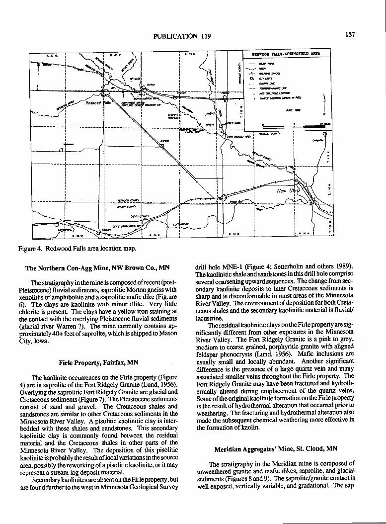
-m--{- dpffi
Bam...... &u-- ffiE|,r
. Fn'ffiLdllu
. #w(Eaa@t
tE r-
II
-+------------IIT
I+-trl
__-______:,rg+Z
I
a------------+-I
iI
III
II
-----------L
I
1-----------III
i it;IIIII
iI
PI'BLICATION 1I9 r57
Figrne 4. Redwood Falls area location map.
The Northern Con-Agg Mine, N\il Brown Co., MN
The stratigraphy in the mine is composed of recent (post-Pleistocene) fluvial sediments, saprolitic Morton gneiss withxenoliths of amphibolite and a saprolitic mafic dike (Fig.ure6). The clays are kaolinite with minor illite. Very litttechlorite is presenl The clays have a yellow iron staining atthe contact with the overlying Pleistocene fluvial sediments(glacial river Warren ?). The mine currently contains ap-proximately 4Gr feet of saprolite, which is shipped to MasonCity,Iowa.
Firle Property, Fairfax' MN
The kaolinite @curences on the Firle property (Figure4) are in saprolite of ttre Fort Ridgely Granite (Lund, 1956).Overlying the saprolitic FortRidgely Granite are glacial andCretaceous sediments (Figure 7). The Pleisocene sedimentsconsist of sand and gravel. The Cretaceous shales and
sandstones are similar to other Cretaceous sedimeng in theMinnesota River Valley. A pisolitic kaolinitic clay is inter-bedded with these shales and sandstones. This secondarykaolinitic clay is commonly found between the residualmaterial and the Cretaceous shales in other parts of theMinnesota River Valley. The deposition of this pisolitickaoliniteisprobably theresultof local variations in the sourcearea, possibly thereworking of apisolitic kaolinite, or it mayrepresent a stream lag deposit material.
Secondarykaolinites are absenton theFirleproperty,butare found further 0o the west in Minnesota Geological Survey
dritl hole MNE-I @gure 4; Seuerholm and othen 1989).
The kaolinitic shale and sandstones in this drill hole compnseseveral coarsening upward sequerrces. The change from sec-
ondary kaolinit€ deposits to later Cretaceous sediments is
sharp and is disconformable in most areas of the Minnesotanivel Valley. The environment of deposition for both Creta-
ceous shales and the secondary kaolinitic material is fluviaVlacusrine.
Theresidualkaolinitic clays on theFirleproperty are sig-nificantly different from other exposures in the MinnesotaRiver Valley. The Fort Ridgely Granite is a pink to grey'
medium to coarse grained, porphyritic granite with alignedfeldspar phenocrysts (Lund, 1956). lvIafic inclusions are
usually small and locally abundant Another significantdifference is the presence of a large quartz vein and many
associated smaller veins throughout the Firle property. TheFort Ridgely Granite may have been fracnred and hydroth-
ermally altered during emplacement of the quartz veins.
Some of the original kaolinite formation on the Firle property
is the result of hydrcttrermal alteration that occurred prior toweathering. The fracturing and hydrothermal alteration also
made the subsequent chemical weathering more effective inthe formation of kaolin.
Meridian Aggregates' Mine, St. Cloud' MN
The sratigraphy in the Meridian mine is composed ofunweathered granite and mafic dikes, saprolite, and glrcialsedimenc @gures 8 and 9). The saprolite/granite contact is
well exposed, vertically variable, and gradational. The sap
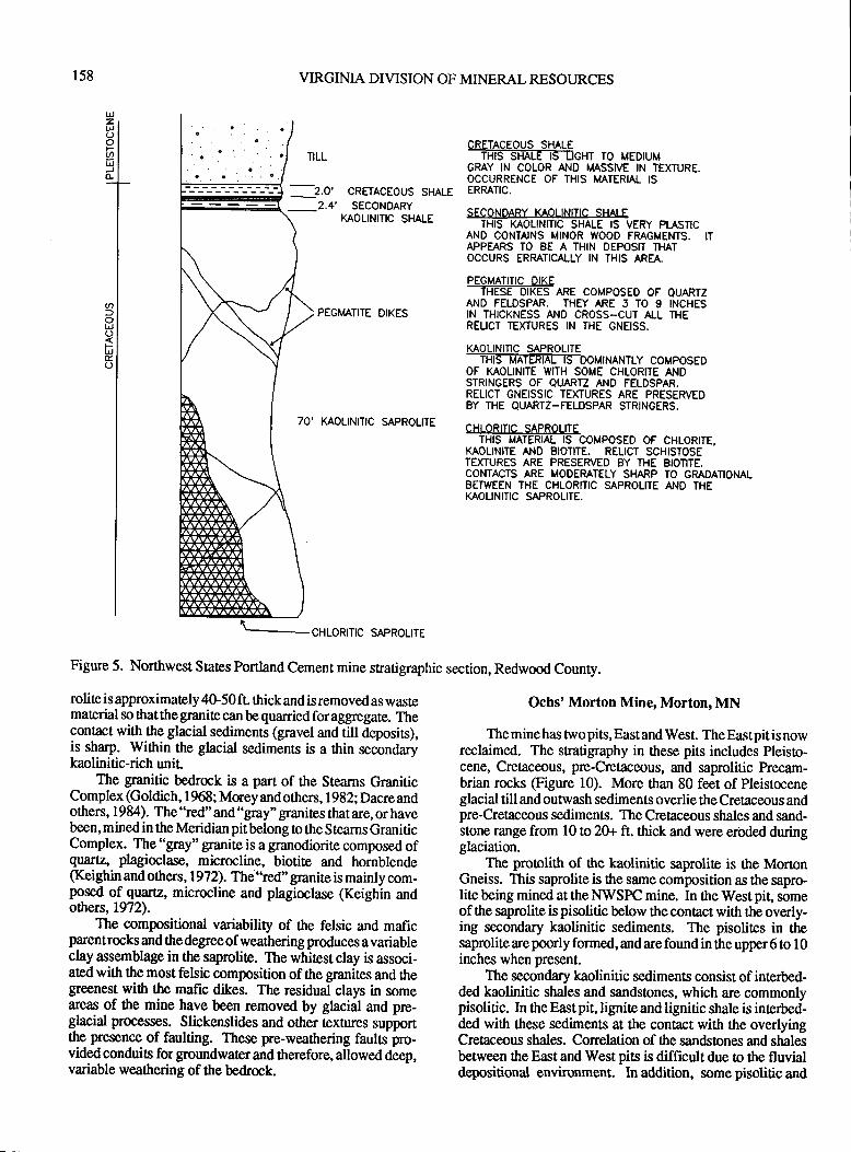
158 VIRGINIA DIVISION OF MINERAL RESOURCES
PEGIvIATITE DIKES
70' KAOLINITIC SAPROLITE
Figure 5. Northwest States Portland Cement mine stratigraphic section, Redwood County.
%W^tE#E*T To MEDT,MGRAY IN COLOR AT.ID MASSTIE N TEXIURE.OCCURRENCE OF THIS MATERIAL ISERRATIC,
SECONDARY KAOLINITIC SHAI FTHIS MOLINITIC SHALE IS VERY PI.ASTIC
AND CONTAINS MINOR WOOD FMGMENTS, ITAPPEARS TO 8E A THIN DEPOSIT THATOCCURS ERMTICALLY IN THIS AREA,
PEGMATITIC DIKETHESE DIKES ARE COMPOSED OF QUARTZ
AND FELDSPAR. THPf ARE 5 TO 9 INCHESIN THICKNESS AND CROSS-CUT ALL THERELICT TEXTURES IN THE GNEISS.
KAOLINITIC SAPROLITE_TFTFNTETIITIS-DoMINANTLY coMPoSED
OF KAOLINITE WIIH SOME CHLORITE ANDSTRINGERS OF OUARTZ AND FELDSPAR.RELICT GNEISSIC TEXTURES ARE PRESERVEDBY THE QUARTZ-FELDSPAR STRINGERS.
CHLORITIC SAPROLITETHIS MATERIAL IS COMPOSED OF CHLORITE,
KAOLINITE AND EIOTITE. RELICT SCHISTOSETEXTURES ARE PRESERVED BY THE BIOTITE,CONTACTS ARE MODEMTELY SHARP TO GMDATIONALBETWEEN THE CHLORITIC SAPROLITE AI.ID THEKAOLINITIC SAPROLITE,
Ochs' Morton Mine, Morton, MN
The mine has two pits, East and West. The East pit is nowreclaimed. The sratigraphy in these pits includes Pleisto-cene, Cretaceous, pre-Cretiaceous, and saprolitic Precam-brian rocks (Figure 10). More ttran 80 feet of Pleistoceneglacial till and outwash sediments overlie the Cretaceous andpre-Cretaceous sediments. The Cretaceous shales and sand-stone ftrnge from 10 to 20+ ft. thick and were erirded duringglaciation.
The proolith of the kaolinitic saprolire is the MoronGneiss. This saprolite is the same composition as the sapro-lite being mined at the NWSPC mine. In the West pit" someof the saprolite is pisottic below the contact with the overly-ing secondary kaolinitic sediments. The pisolites in thesaprolite are poorly formed, and are found in the upper 6 to 10inches when present.
The secondary kaolinitic sediments consist of interbed-ded kaolinitic shales and sandstones, which are commonlypisolitic. In the East pit, lignite and lignitic shale is interbed-ded with these sediments at the contact with the overlyingCretaceous shales. Correlation of the sandsones and shalesbetween the East and West pits is difficult due to the fluvialdepositional environment. In addition, some pisolitic and
TILL
_2.0'_2.4',
CRFTACEOUS SHALESECONDARY
KAOLINITIC SHALE
rolite is approximately 4G50 ft. thick and is removed as wastemat€rial so that the granite can be quarried for aggregate. Thecontact with the glacial sediments (gravel and till deposits),is sharp. Within the glacial sediments is a ttrin secbndarykaolinitic-rich unit
The granitic bedrock is a part of the Stearns GraniticComplex (Goldich, 1 968 ; Morey and others, 1 982; Dacre andothers, 1984). The "red" and "gray" granites tlnt are, or havebeen, mined in the Meridian pit belong to the Stearns GraniticComplex. The "gray" granite is a granodiorite composed ofqvutz, plagioclase, microcline, biotite and hornblende(Keighin and others, 1972). The "red" granite is mainly com-posed of quattz, microcline and plagioclase (Keighin andothers, 1972).
The compositional variability of the felsic and maficparentrocks and the degreeof weathering produces avariableclay assemblage in the saprolite. The whitest clay is associ-ated with tlrc most felsic composition of the granites and thegreenest with the mafic dikes. The residual clays in someareas of the mine have been removed by glacial and pre-glacial prooesses. Slickenslides and other t€xtures supportthe presence of faulting. These pre-weathering fauls pro-vided conduits for groundwater and herefore, allowed deep,variable weathering of the bedrock.
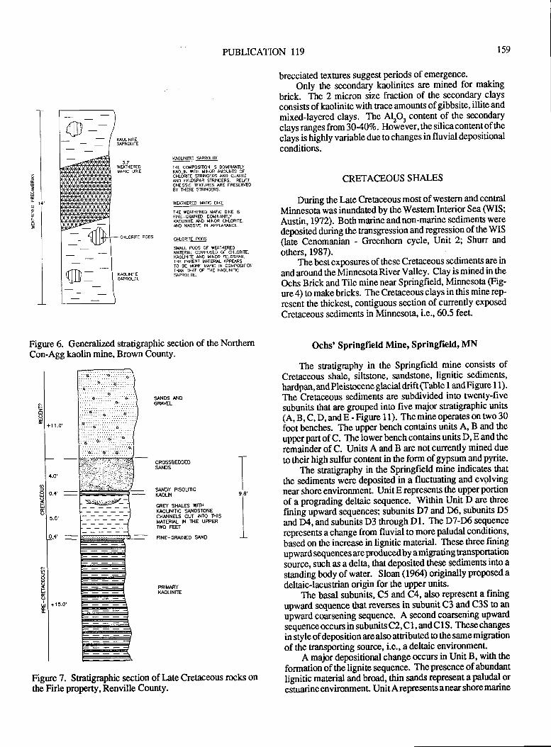
PUBLICATION 119 r59
1
I
3-
Figure 6. Generalized stratigaphic section of the NorthemCon-Agg kaolin mine, Brown County.
brecciated textures suggest periods of emergence.
Only ttre secondary kaolinites are mined for making
brick. The 2 micron size fraction of the secondary claysconsists of kaolinite with trace amounts of gibbsite, illite and
mixed-layered clays. The AlO, content of the secondary
clays ranges from *T-qOEo. Hoivever' the silica content of the
clays is highly variable due to changes in fluvial depositionalconditions.
CRETACEOUS SHALES
During the Late creAceous most of western and central
Minnesota was inundatedby theWestem Interior Sea (WIS;
Austin, 19?2). Both marine and non-marine sediments were
deposited during the nansgression and regression of the WIS(late Cenomanian - Greenhorn cycle, Unit 2; Shun and
others, 1987).The best exposures of these Cretaceous sediments are in
and around the Minnesota River Valley. Clay is mined in the
Ochs Brick and Tile mine near Springfield, Minnesota (Fig-
ure 4) to make bricks. The Cretaceous clays in this mine rep-
resent the thickest, contiguous section of currently exposed
Crebceous sediments in Minnesota, i.e.,60.5 feet.
Ochs' Springfield Mine, Springfield' MN
The snatigraphy in the Springfield mine consists ofCretaceous shale, siltstone, sands[one, lignitic sediments,
hardpan, and Pleistocene glacial drift (Table I andFig* I t).The
-Cretaceous sediments are subdivided inio twenty-five
subunits that are grouped into five major stratigraphic units(A, B, C, D, and E - Figure I 1). The mine operates on wo 30foot benches. The upper bench contains units A, B and the
upper part of C. The lower bench contains units D, E and the
remainder of C. Unis A and B are not currently mined due
to their high sulfur content in the form of gypsum and pynte.
The stratigraphy in ttre Springfield mine indicates that
the sedimens were deposited in a fluctuating and evolvingnear shore environment. Unit E represents the upper portion
of a prograding delaic sequence. Within Unit D are three
fining upward sequences; subunits D7 and D6, subunits D5
and Dl, and subunits D3 tlrough Dl. The D7-D6 sequence
represents a change from fluvial to more paludal conditions,
based on the increase in lignitic material. These three finingupward sequences are produced by a migrating tansportationsource, such as a dela, *rat deposited these sediments ino a
standing body of water. Sloan (1964) originally proposed a
deltaic-lacusrian origin for the upper units.The basal subunits, C5 and C4, also represent a fining
upward sequence that revenes in subunit C3 and C3S to an
upward coarsening sequence. A second coarsening upwardsequence occurs in subunits C2, C 1, and C I S. These changes
in style of deposition arealso attributed to the samemigrationof the transporting source, i.e., a deltaic environment.
A major depositional change occtus in Unit B, with the
formation of the lignite sequence. The presence of abundant
lignitic material and broad, ttrin sands represent a paludal oreJtuarine environment. Unit A represents a near shore marine
NOUNIiC SAPROLITE
THE COMPOSITION IS DOMIMI{TLYNOLIN WIH MINOR AMOUNTS OFCHLORITE STRINGERS NO QUARTZNO FEOSPAR SMINCERS. REUCTCNEISSIC EXTURES ARE PRESERVEO8Y THESE SRINCERS.
WTIIHEREO I.{AFIC OIKE
THE WF}THEREO MfIC OIKE IS
FNE_CRAINEO, OOUINAITLY$OLINITE ND MINOR CHLORITE,NO USSIVE )N APPANCE,
CHLORITE POOS
SMIL POOS OF WSTHEREDMIERAL COMPOSEO OF CHLORIIE,SOLINIE NO MINOR FELOSPAR.THE PAFENT MAIERII APPEARSTO AE MORE MMC IN COMPOSII]ONTHAN THAT OF NE KAOUNITIC9PROLIE.
CHLORIIE PODS
".1zl
HI*
|
+r r.o'
I
I
I
I r'o'
alilo.*'
-EIEIal
l'"'lo.4'
-I"l5l8l
EIol$ l+ts.o''l
I
I
I
SANOS AI.IDCRAVEL
CROSSBEDOEDSANOS
SANOY PISOUTICKAOLIN
GRFI SI{ALES VYITH
K^OUNINC SANDSTONECHANNELS CUT INTO THISMATRhL IN THE UPPERIWO FEfi
NNE-GRAINEO S\ND
i9,8'
PRITARYKAOLINITE
Figure 7. Statigraphic section of late Cretaceous rocks onttre Firle property, Renville County.
fiT\ -\il il _ -
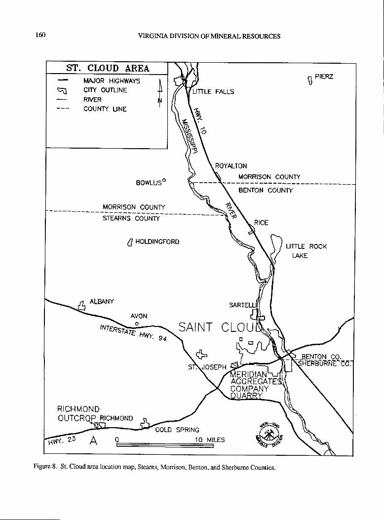
160 VIRGINIA DIVISION OF MINERAL RESOURCES
ST. CLOUD AREA
BOWLUSO
MORRISON COUNTY---->sSTEARNS COUNTY
4l HOLDTNGFORD
ALBANY
AVONe-.* SAINT CLOUFo
*\,tosEpH
MAJOR H|GHWAYS tE crw ouruNE tRIVER flCOUNTY LINE
,.u*r*-iit)
RICHMONDOUTCRQP RICHMOND
BENTON CO.itie-n-eT,r-n-lrE-Cd.
ERIDIANAGGREGACOMPANY
O 10 MILES
Figure 8. St. Cloud area location map, Stearns, Morrison, Benton, and Sherburne Counties.
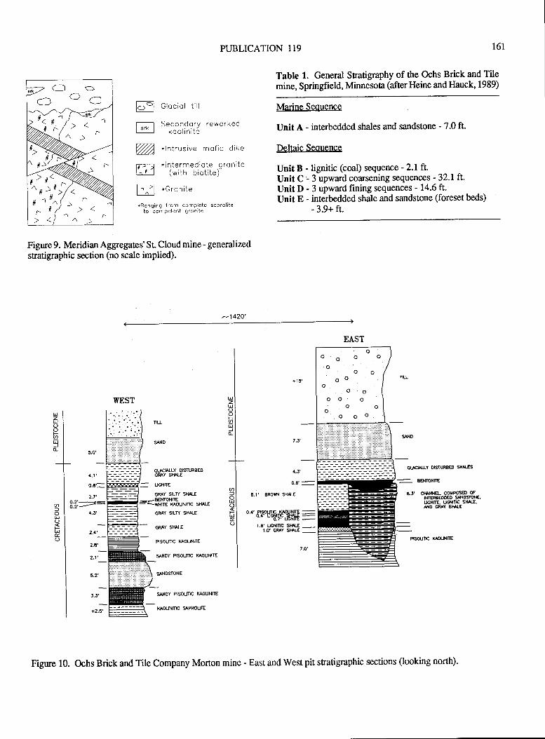
PUBLICATION 119 161
Glocial iill
Secondory reworkedko o linite
*lntrusive mofic dike
*intermediote .gronite(with biotite)
B *G'onii"
*Ronging from complete soprolileto compelent gronite
Figure 9. Meridian Aggregates' St Cloud mine - generalized
sftatigaphic section (no scale implied).
Table 1. General Sratigraphy of ttre Ochs Brick and Tilemine, Springfield, Minnesota (after Heine and llauck, 1989)
Marine Seouence
Unit A - interbedded shales and sandstone - 7.0 ft.
Deltaic Sequence
Unit B - lignitic (coal) sequence -2.1ft.Unit C - 3 upward coarsening sequences '32.I ft.Unit D - 3 upward fining sequences - 14.6 ft.Unit E - interbedded shale and sandstone (foreset beds)
- 3.9+ ft.
cLro tLY usn RBeo sH^tls
l^ -llvl
lsrkl
mffi
-142Q'
UzU
Fatro-
6=U(JsUE(J
UzUoq.U)
v)l
Ostru
3:1:-:
5.0'
4.1'
2.7'
a.J'
2.+',_
2.6
2.1'_
CTACIAITY OEIURSEOORAY SHALE
= ucNlrE
CRAY SIL]Y SMLE
K OUN|TIC 5|l l-E
SANOSrcNE
ORAY SILW SHALE
GRAY S}TALE
RSOUIIC kAOUNIIE
SANOY PISOUTIC XAOUNITE
5.1, BRoVX SIULE
."EfpHrt,}{$HiuiiF=
I .6' UGNmC ${^rr -_1.0' cn^Y S||rlE _
,+.J'
0.6'::
Ptsoulrc laouN[E
SAIIOY PISOLMC KAOUNITE
KAO{"INIIIC SAPROUTE
t-,, >* lna(
EAST
ITEST
Figure 10. Ochs Brick and Tile Company Morton mine - East and West pit stratigaphic sections (looking north).
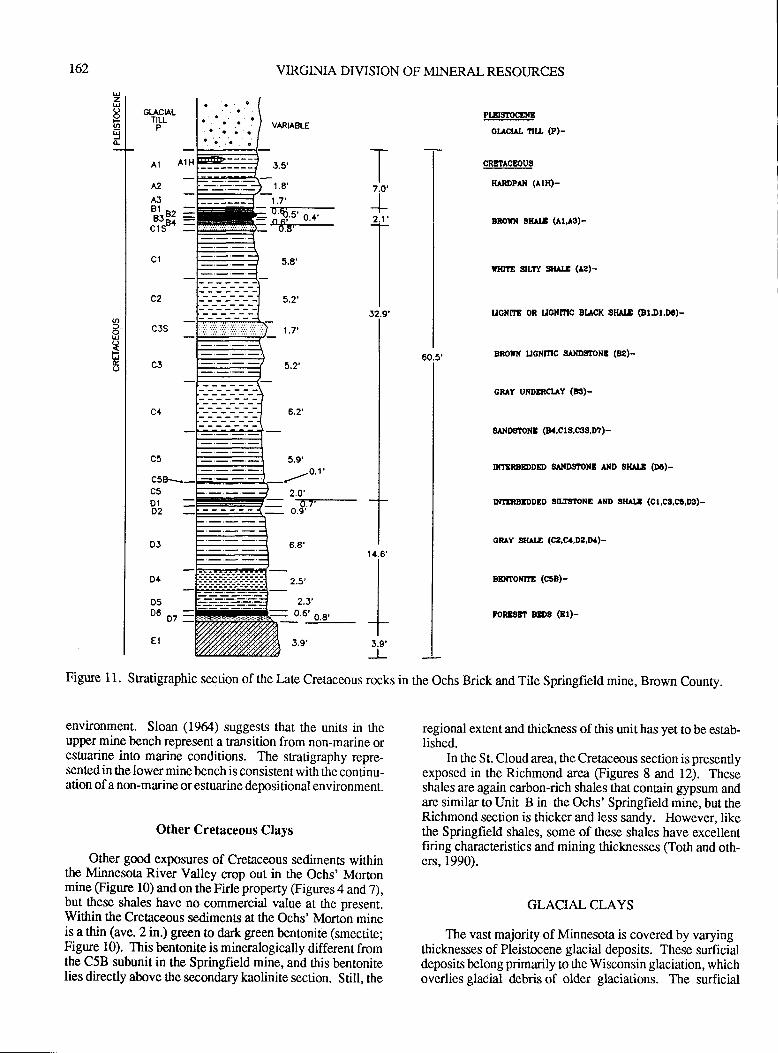
r62 VIRGINIA DIVISION OF MINERAL RESOURCES
5.9'
2,O'-d.7--o.9'
6.8'
_r.t'2.3'
FJ6-os--
environment. Sloan Q964) suggests that the units in theupper mine bench represent a transition from non-marine orestuarine into marine conditions. The sradgraphy repre-sentedin the lower minebench is consistentwith the continu-ation of a non-marine or estuarine depositional environment.
Other Cretaceous Clays
Other good exposures of Cretaceous sediments withinthe Minnesota River Valley crop out in the Ochs' Mortonmine Sigure 10) and on rhe Firle property (Figures 4 and,1),but these shales have no commercial value at the present.Within the Cretaceous sediments at the Ochs' Morton mineis a thin (ave.2 in.) green to dark green bentonite (smectite;Figure 10). This bentonite is mineralogically different fromthe C5B subunit in the Springfield mine, and ttris bentonitelies directly above the secondary kaolinite section. Still, the
PtxrsrocrxE
or.lctlt. nu, (P)-
cRgtAcEous
HIRDPAN (AlH)-
BROIT 8l|^rl (A1"a3)-
rHnE $LTY sr^ll (A2)-
ucilnE 0R uGNnrc Bucl( sHr|x @l,Dr,Dc)-
tRorx ucilt?rc lrlxDsrol|l (Be)-
cRrY UNDERCUY (e!)-
SATDSiONB (8.,C rs,C3S,D?)-
nranaSDDED SAilDS'ONE AXD Sl{Al.E (D6)-
INilRBIDDED SILG'IIONE AND SK^T.B (CI.C3,CI.D3)-
GR Y $rrl.f (c2,oa,D2,IX)-
BEnroxm (coB)-
FoR$rBr 8ED3 (Et)-
regional extent and tlickness of this unit has yet to be estab-lished.
In the St. Cloud area, the Cretaceous section is presentlyexposed in the Richmond area (Figures 8 and 12). Theseshales are again carbon-rich shales that contain gypsum andare similar to Unit B in the Ochs' Springfield mine, but theRichmond section is thicker and less sandy. However, likethe Springfield shales, some of these shales have excellentfiring characteristics and mining thicknesses (Toth and oth-ers, 1990).
GLACIAL CLAYS
The vast majority of Minnesota is covered by varyingthicknesses of Pleistocene glacial deposits. These surficialdeposis belong primarily to the Wisconsin glaciation, whichoverlies glacial debris of older glaciations. The surficial
GLACIALTILL
P
T7.O'
I
2.1'
I52.9'
I
I
I
I
+I
1 4.6',
I
+
J.5'
1.8',-t,l'
:F;r-T.g'-
Figure I 1. Stratigraphic section of the l,ate Crelaceous rocks in the Ochs Brick and Tile Springfield mine, Brown Counry.
AI
t2.
AJot
ut5
c2
c4
c5
c5B'\
D1o2
3.9',
D.+
n<Dt o,
E1
60.5'
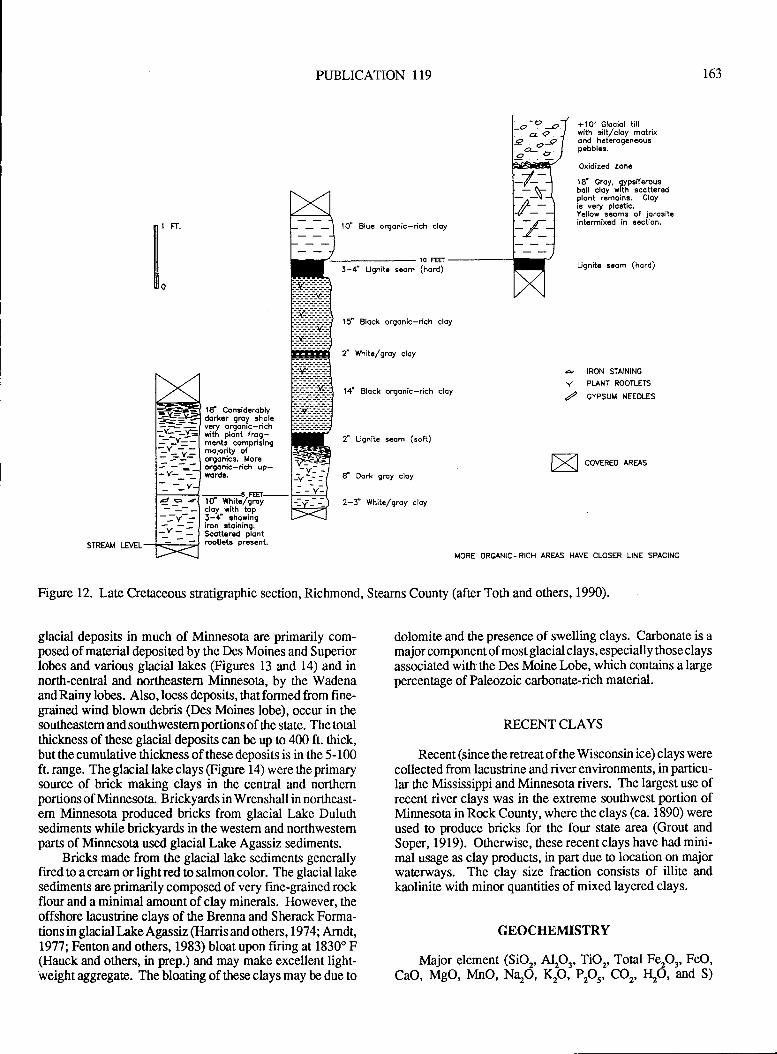
PUBLICATION 119
t O' Bluc orgonic-rich cloy
10 FEET
3-,t' Llgnit€ smm (hord)
I5l Block orgonic-rich cloy
2" White/groy clcy
'l.f Block orgonic-rich cloy
/ Lignitc scom (soft)
d Dork grcy cloy
2-J" White/groy cloy
+10' Glociol tillwith silt/cloy motrixond hcterggcn.ousp€bbl€s.
Oxidized zon.
l8f Groy, gypsiferousboll cloy with scqtt€redplont remoins. Cloyis v€ry plostic.Yello, scoms of jorositcintcrmixcd in section,
Ugnite s€om (hord)
163
il:"
d IRCI.I STAINING
Y PLANT ROOTLETS
Z GYPSUM NEEDLES
td Consideroblydork€r grcy 3holevcry orgonic-richwith plont frog-ments omprisingmo jority oforgonics, Moreorgonic-rich up-words.
-5
FEET-lC Whitcrzgrcycloy vith tqpJ-,t: ehowirigtroo ltornrn9.Ssttered plontmUcts prcsent.
glacial deposits in much of Minnesota are primarily com-posed of material depositedby the Des Moines and Superiorlobes and various glacial lakes @gures 13 and 14) and innorth-cenEal and northeastem Minnesota, by the WadenaandRainy lobes. Also,loess deposits, thatformed from fine-grained wind blown debris (Des Moines lobe), occur in thesouthqntem and southwestem portions of the state. The totalthickness of these glacial deposits can be up to 400 ft. thick,but the cumulative thickness of these deposits is in the 5- 100ft. range. Theglacial lake clays (Figure 14) were theprimarysource of brick making clays in the central and northernportions of Minnesota. Brickyards in Wrenshall in northeast-em Minnesota produced bricks from glacial Lake Duluthsediments while brickyards in tle western and northwestemparts of Minnesota used glacial Lake Agassiz sediments.
Bricks made from the glacial lake sediments generallyfired to a cream or light red to salmon color. The glacial lakesediments are primarily composed of very fine-grained rockflour and a minimal amount of clay minerals. However, theoffshore lacustrine clays of the Brenna and Sherack Forma-tions in glacial Lake Agassiz (Hanis and others, 1974; Arndt,1977; Fenton and others, 1983) bloat upon firing at 1830' F(Hauck and others, in prep.) and may make excellent light-weight ag$egate. The bloating of these clays may be due to
-Y=
lY coueaeo *ans
STRAM LEVRMORE ORGANIC-RICH AREAS HAVE CLOSER LINE SPACING
Figure 12. Late Cretaceous stratigaphic section, Richmond, Stearns County (after Toth and ottrers, 1990).
dolomite and the presence of swelling clays. Carbonate is amajor component of most glacial clays, especially those claysassociated with ttre Des Moine Lobe, which contains a largepercentage of Paleozoic carbonate-rich material.
RECENTCLAYS
Recent (sincetheretreatof theWisconsin ice) clays werecollected from lacustrine and river environments, in particu-lar the Mississippi and Minnesota rivers. The largest use ofrecent river clays was in the extreme southwest portion ofMinnesota in Rock County, where the clays (ca. 1890) wereused to produce bricks for the four state area (Grout andSoper, 1919). Otherwise, these recent clays have had mini-mal usage as clay products, in part due !o location on majorwaterways. The clay size fraction consists of illite andkaolinite with minor quantities of mixed layered clays.
GEOCHEIVIISTRY
Major element (SiO2, AIP' TiO' Total Fep' FeO,
CaO, MgO, MnO, NqO, I!O, PP' CO2, ILO, and S)
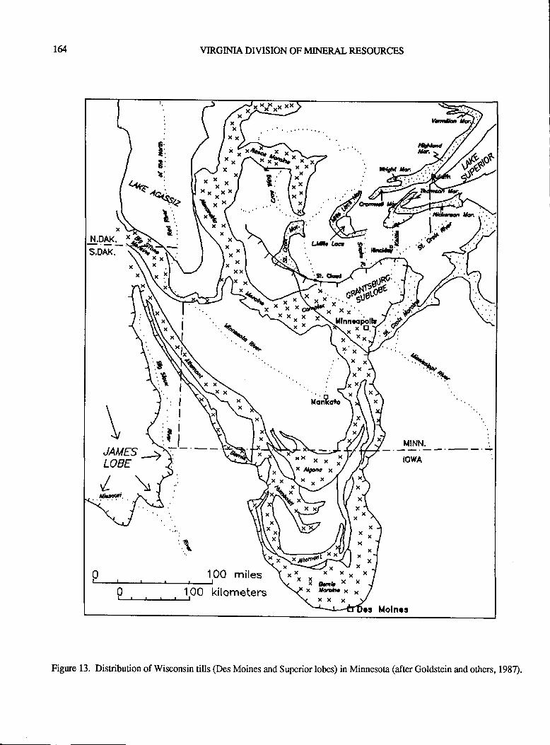
r& VIRGINIA DTVISION OF MINERAL RESOURCES
Figure 13. Distribution of Wisconsin tills (Des Moines and Superior lobes) in Minnesota (after Goldstein and others, 1987).
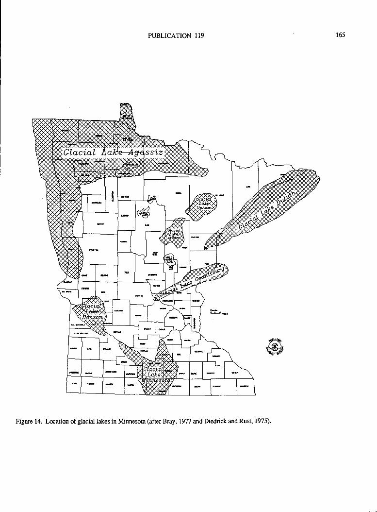
PUBLICATION 119 165
GLacial
ffi'
Figure 14. Location of glacial lakes in Minnesota (after Bray, 1977 and Diedrick and Rust, 1975).
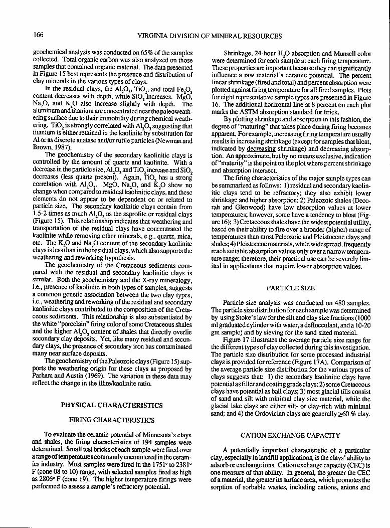
t6 VIRGINIA DIVISION OF MINERAL RESOURCES
geochemical analysis was conducledon65Vo of the samplescollected. Total organic carbon was also analyzeAon tlosesamples that contained organic material. The data presentedin Figure 15 best represents the presence and distribution ofclay minerals in the various types of clays.
In the residuul gluyl, the A!p'T!O' and toral Fep,content decreases with depth, wtiitrj Sio"increases. V{O,Nap, and IlO also increase slightly wittr depn. Thealuminum and titanium are concentrated near the paleoweath-ering surfacedue o their immobility during chemical weath-ering. TiO, is strongly correlated with AlO, suggesting thattitanium is eitherretained in the kaoliniteby substitution forAl or as discrete anatase and/or rutile particles (Newman andBrown, 1987).
The geochemistry of the secondary kaolinitic clays iscontrolled by the amount of quaru and kaolinite. With adecrease in the particle size, AlO, and TiO, increase and Siedecreases (less quartz presen[).
- Again, iiO, has a srong
correlation with Alpr. MgO, Nap, and Kp show nochange when compared to residual kaolinitic clays, and theseelements do not appear to be dependent on or related topafticle size. The secondary kaolinitic clays contain from1.5-2 times as much ALQ * the saprolite or residual clays(Figure l5). This relationihip indicates that weattrering anOtransportation of the residual clays have concentrated thekaolinite while removing other minerals, e.g., quartz, mica,erc. The \O and NqO content of the secondary kaoliniteclays is less-than in theiesidual clays, which also supports ttreweathering and reworking hypothesis.
The geochemistry of the Cretaceous sediments com-pared with the residual and secondary kaolinitic clays issimilar. Both the geochemistry and the X-ray mineralogy,i.e., presence of kaolinite in both types of samples, suggestsa common genetic association between the trpo clay types,i.e., weathering and reworking of the residual and secondarykaolinitic clays conributed to ttre composition of the Creta-ceous sediments. This relarionship is also substantiated bythe white "porcelain" firing color of some Cretaceous shalesand the higher AlO, content of shales that directly overliesecondary clay deposits. Yet, like many residual and secon-dary clays, the presence of secondary iron has contaminatedmany near surface deposis.
The geochemistry of thePaleozoic clays (Figure 15) sup-ports the weathering origin for these clays as proposed byParham and Austin (1969). The variation in these data mayreflect the change in the illite/kaolinite ratio.
PHYSICAL CHARACTERISTICS
FIRING CHARACTERISTICS
To evaluate the ceramic potential of Minnesota's claysand shales, the firing characteristics of 194 samples weredetermined Small test bricks of each sample were fired overa range of temperatur€s commonly encountered in ttre ceram-ics indusry. Most samples were fired in the 1751" to 2381'F (cone 08 to l0) range, with selected samples fired as highas 2806" F (cone 19). The higher temperature firings wereperformed 0o assess a sample's refractory potential.
Shrinkage, 24-hour {O absorption and Munsell colorwere determined for each sample at each firing temperature.These properties are important because they can significantlyinfluence a raw material's ceramic potential. The percentlinear shrinkage (fired and total) and percent absorption wereplotted against firing temperature for all fred samples. Plosfor eight representative sample types are presented in Figure16. The additional horizontal line at 8 percent on each plotmarks the ASTM absorption standard for brick.
By plotting shrinkage and absorption in this fashion, thedegree of "maturing" that takes place during firing becomesapparenl For example, increasing firing temperature usuallyresults in increasing shrinkage (except for samples that bloat,indicated by decreasing shrinkage) and decreasing absorp-tion. An approximate, butby no means exclusive, indicationof "maturity" is the point on the plot where percent shrinkageand absorption intersect.
The fuing characteristics of the major sample types canbe summarized as follows: l) residual and secondary kaolin-itic clays tend to be refractory; ttrey also exhibit lowershrinkage and higher absorption; 2) Paleozoic shales (Deco-rah and Glenwood) have low absorption values at lowertemperatues; however, some have a tendency to bloat (Fig-ure 16); 3) Cretaceous shales have the widestpotential utility,based on their ability to fire over a broader (higher) range oftemperatures than most Paleozoic and Pleistocene clays andshales; 4) Pleistocene materials, while widespread, frequentlyreach suitable absorption values only over a narrow tempera-ture range; tlerefore, their practical use can be severely lim-ited in applications that require lower absorption values.
PARTICLE SIZE
Particle size analysis was conducted on 480 samples.The particle size distribution for each sample was determinedby using Stoke's law for the silt and clay size fractions (1000ml graduated cylinder with water, a deflocculant, and a 10-20gm sample) and by sieving for the sand sized material.
Figure 17 illustrates the average particle size range forrhe different types of clay collected during this investigation.The particle size disribution for some processed industrialclays is provided forreference @gure 17A). Comparison ofthe average particle size distribution for the various types ofclays suggests that 1) the secondary kaolinitic clays havepotential as fi ller and coating grade clays; 2) some Cretaceousclays have potential as ball clays; 3) most glacial tills consistof sand and silt with minimal clay size material, while theglacial lake clays are either silt- or clay-rich with minimalsand; and 4) the Ordovician clays are generally 2ffi Vo clay.
CATION EXCHANGE CAPACITY
A potentially important characteristic of a particularclay, especially in landfill applications, is the clays' ability toadsorb or exchange ions. Cation exchange capacity (CEC) isone measure of that ability. In general, the greater ttre CECof a material, the grcater its surface are4 which promotes thesorption of sorbable wastes, including cations, anions and
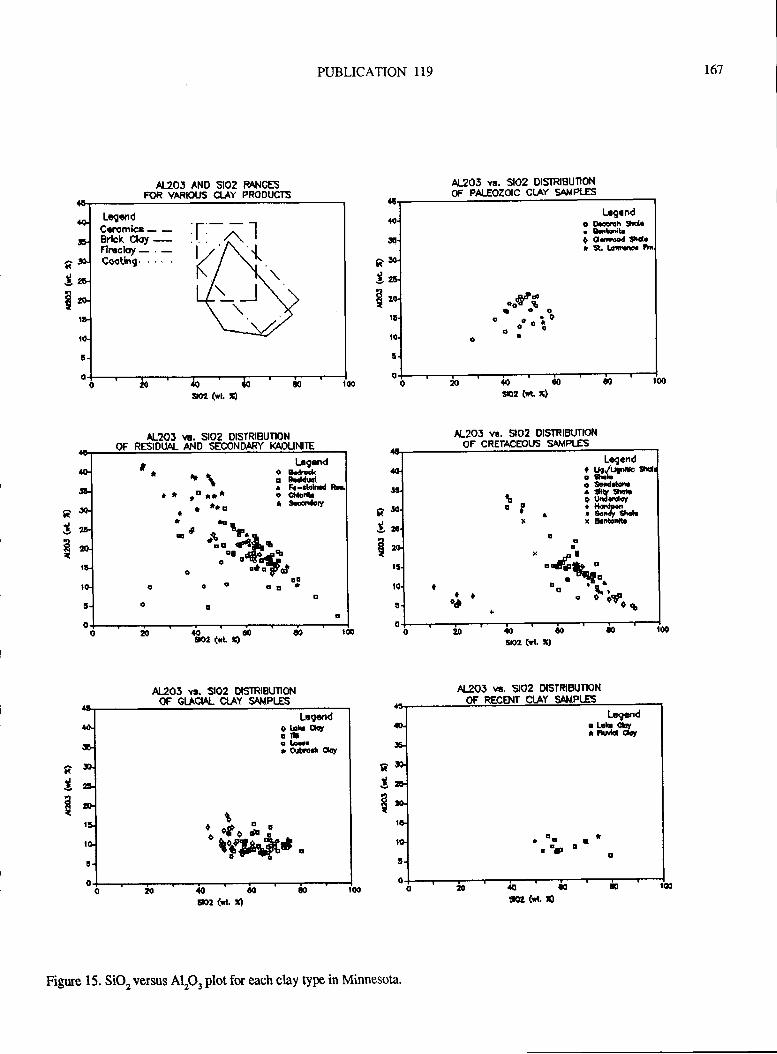
PUBLICATION 119
Al20J AND SlO2 Ml.lGiESFOR VARIOUS CLAY PROOUCTS
r6'7
n3
E
al
3FI
AlJ05 vs. SlO2 D|S|REU[S{OF PALEOZOIC CLAY SAXPI-ES
lrl-2oJ vt. 5lO2 USTRIzuTIONOF CRETACEOUS SAT.IPI-ES
xg
E
nIR
f;$?lt
xspll
soa (rl r)
l,rg.ndo DFqlh War Eataib0 Orrbad td.
snu (*c :)
[rgond* *\ lijffi..f ro'.. 3!;,-.*l*
a 't
'-o I 3'oondolt
I t.-, o of,.-
+io dtilto"t o4"i*,*
o q," fdo o o oo ol
Lcgcnd0 uq.4jF|f,c! gr.bo $rdrlctr tlU trcbO thdrdot+ llattimr Sody Srokx E trtodtr
oo,./!':B;,
t ol .
-.'ot';*o*
5O7r (vt, X)
Al2O5 vs. S|O2 DISTRIBUTIONOF GIICIAL C1AY SAilPtIS
5o1 (rl. r)
tibbi#*"
AJOS w. StOz DlSTRlzuTKlil
ga' (r( S
Figure 15. SiO, versus Alp, plot for each clay type in Minnesota.
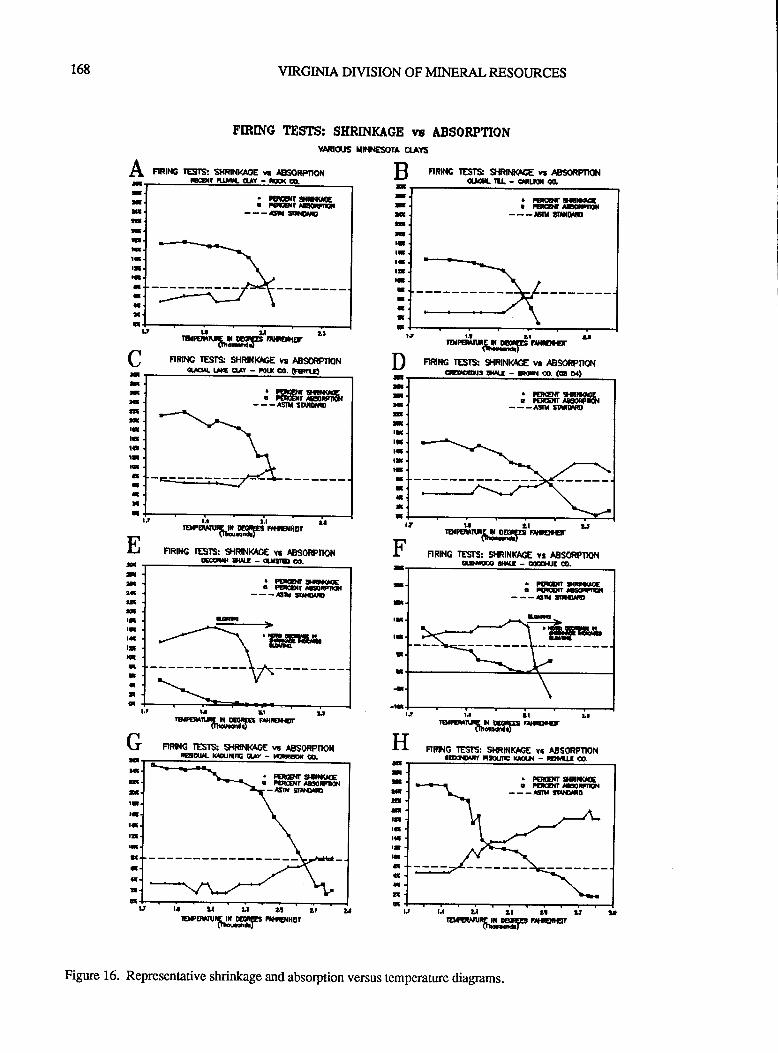
168 VIRGINIA DIVISION OF MINERAL RESOURCES
FIRING TESTS: SHAINKACE w ABSORpTIONvAF|qJli Xtl[\ES(m A yS
BI
-:T!nrlItt-t!f,rTctG
IITtta
A ** rEilIi: slftNt4EE vr TESOFFTKI{
. PqCO|t l'|OtqEC! ftrl{t t!!r'|nl---sn rmru
T-:ICt!TIGrEltrtt
tr,arftiar_
RRP{G IESI* SHRIilMC€ r! AESffiONqraru |JtE tl Y - iIX O0. (FErn-E}
RRlt{G IESIS SlRb{4c€ }r ABSQRflONotL[ ru - G|itrai 00,
. luco? tltlarlcCr rE|Ear aHP|tna---Etx tilftoro
f,l lt-o*tlhl,IIHF ?frEr€
FRNG IESIS: SHRINKrcE rn ABSORPITO{Etnatur! tr(t - r(lr{ o. (c D0'Ja
3:nallrtttl'lIIITIIaa]a
t.t
11
E-T*frTr-T!tlltlHaIIII
t:tt-/.9t
-artcrtrlItI'lIC;IaI
-
G
rr tJ r;l"' 'urriirufrgleelFi''r*m,xat
,
FIRIHG IESI$ s|{RtNlficE vr AB!}ORpItOtlEoA{l trfal - qJ$El oO.
. FW-t{t ltQltoEE! F|'EF{I .BFf,OI---rlrx 3flNut!}
tJ lrtD..E{|.rfi##$rE F|r|rEr+:r
FIRING TEIS: SltRlNKqOt \6 tBSOFPnOilE! UrrL kqjl|tE nLrY - |tltiE( ao.
. FqB|I g\Rt|(|tEE FftE{t
'|!EFIX'{I - Elx li?rfQrtrl
. maofi ttraqcE! ?ftE{r lSlnFDOl---ASr{ t9ItSiO
t.a 2t urEBruffigsF lttE nr
FIRING lESrS: SflRltll(lcE vr AESoRPIXXct5\r@ Tx{I - qE{E Ca.
. PEEttrr tilta(tot. r|ncErr |!gl|rE{- - -tt|r. tfl.OrG
'dl'A_-_-)
.rq--,- I 'ir#:F
\l.l llt tt
-o-ET"gH:5l8 m{o.rtr
FIRING IESrS: SHRF{I$6E vc ABSORPTIONtltxro.Ft Fu.mc ucr{ - rDa^JJ o.
F
aattrarlItqtt-*!r
*I:t|ltanIElqllr-G;C{!ail
Lt uftttt!2lDPErnrhgg[F Hria.Hur
tr ',t
tt !t ,.1*T'{,.H3prEtGrGr
Figure 16. Representative shrinkage and absorption versus temperature diagrams.
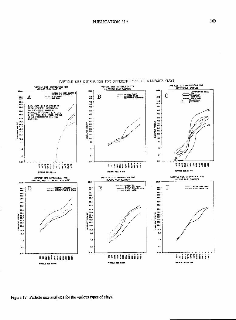
PUBLICATION 119
PARTICLE SIZE DISTRIBUTION FOR DIFFERENT TYPES OF MINNESOTA CTAYS
r69
0,1
0.01
0.1
q01
t.n
-g9l€5s3BO
F.0
F.q
&.0
F 70.0
B E.qE S.o1*.0Eu=
a.o
=o to.o
F.S
s.taaJ
9!i9.0F'
s-os-o
t0,F ?Dt
H;;t to.oI a.ot5 r.00 to.o
ao
1.0
S,F
et.999.4
s.5gs-o
s.o
t!.os.o
&.o
- 70.0
6 *.0ff s.0t *.0> 30.0
= 8.O
=' to.o
1-O
E.r
tr.3s.tP59-0*.0
E.q
F,O
&.0
Fru3rufr o.0aaolru=ru3o rdo
!!
t9,9e
*.9F,E
F,tB',40
t5.0
$.0
DJF ?o-o
F m.o
F oo,- s-o! w-o
5 ZOpto l[o
1.0
99-€
t.9ttt,!x4ta.0
$Tis,0
ra0
t D-D
f ooI bo,- {.0I rc-o
i 20J
a toJiD
1.O
PAET]CIE SIZE OISTRIBUNON TSIVARIOIIS CIAY SA,IPLES
PrP9P9p9pPe9sEEETEC:gEFEmEMtu|E
PTRTICIE SIZE DISTRIgUTION FORRESDTIL t]10 SEOOfDAF/ t(^OLNm
PAR'TEIE SIZE OSTNtsIMON FOR
- DEootr s{4tr
LJ - -GreSIEjJ ---- s.r,tft€icE FDR*IJX'N
N-ooeoo9999pbBEBiEq:EER9PAXTrcIT S{E H m
PIRTICIE s|ZE TTSTRIEUTION FOR
oJiDlal c[.qY SAuFLES
H:GI CACtrl/.i[d.st
ruuxE cuEffiuEtlEss
broooeoOaP99irBbitit?3!F$cffiUxm
PAfftCtE SIZE o{STRlEUTlOfl FoR
CRETTEOUS sr{'tLES
P.999PP99P99EEEEEFg:EEEEmEU EZE N nF
PARTICN-E $ZE DISIRBI'TIOil TOR
RECEM CIAY S,{'PLES
[]
-
MKchYL ---- n@T ffiR u
$rgE;gqSEEE!
T\
-EoqN| , ---- E$(lA Cri-fiTE drYS'........ 6daMm cus
NJoFoqosocooEbEBbE,iiS9lS9ilElgX m
q1
0.ol
-
ffic ct f FNE NttlmCqN qY W3n -..- fi-trn usn . &cuY
OATA USED IN TI-II5 FXIJfiE 15
FROT4 INDUSTRI NFORMATIOTIOH PROCESSED MATERIAL.5A}IPI.ES III FIGT,IRES B. C. A€O T4AY FALL h{TO TI-IESE RAIIG€SAFTER PROCESSf.IG'IHE RAJIMATERFL
/// '/.i' I
/i1..- .2r: ".'.:V
-.._ reffALKrc rur EsSffiru :..... s{rY $+{E,,----,,$MruB-!EmffE
Figure 17. Particle size analyses for the various tlpes ofclays.
r70 VIRGIMA DIVISION OF MINERAL RESOURCES
Univ. Minn., Minneapolis,53 p.
Bray, 8.C., 1977, Billions of years in Minnesota: Thegeological story of the State: St. Paul, North Cenral publish-ing Co., 102 p.
Dacre, G.A., Him melberg, G.R., and Morey, G.8., 1984, Pre-Penokean igneous and metamorphic rocks, Benton and SteamsCounties, central Minnesota: Minn. Geol. Survey, Rept. Inv.31, 16 p.
Dawson, G.W., and Mercer, B.W., 1986, Hazardous wastemanagemenf John Wiley and Sons, New York,522 p.
Diedrick, R.T., and Rust, R.H., 1975, Glacial lake evidencein western Minnesota as interpreted from the soil survey: J.Minn. Acad. Sci., v.41, p. 9-13.
Fenton, M.M., Moran, S.R.,.Teller, J.T., and Clayton, L.,1983, Quaternary stratigaphy and history in the sou*rern partof the Lake Agassiz basin: in Teller, J.T., and Clayton, L.,(eds.), Glacial Lake Agassiz: Geol. Assoc. Canada, Spec.Papr26,p.49-74.
Goldich, S.S., 1938, A study in rock weathering: J. Geol., v.46,p.17-58.
Goldich, S.S., 1968, Geochronology in the Lake Superiorregion: Can. J. Earth Sci., v. 5, p. 715-724.
Goldich, S.S., Wooden, J.L., Ankenbauer, Jr., G.A., Levy,T.M., and Suda, R.U., 1980, Origin of the Morton Gneiss,southwestern Minnesota: Part 1. Lithology: Geol. Soc.America, Spec. Paper 182, p. 45-56.
Goldstein, 8., Mooen, H., Keen, K., Norton, A., and Cherni-coff, S., 1987, Geomorphology and Pleistocene glacial geol-ogy of central Minnesota: Minn. Geol. Survey, GuidebookSer. No. 16,p.146.
Grout, F.F., 1947, Minnesota building brick and tile: Minn.Geol. Survey., Summary Rept 2,7 p.
Grout, F.F., and Soper, E.K., 1919, Clays and shales ofMinnesota: U.S. Geol. Survey, Bulletin 678,259 p.
Haas, L.A., Aldinger, J.A., Blake, R.L., and Swan, S.A.,1987, Sampling, characterization, and evaluation of midwestclays for iron ore pellet bonding: U.S. Bur. Mines, Rept.Inv.9116,44 p.
Ilarris, K.L., Moran, S.R., and Clayton, L., 1974, Late eua-ternary sfatigraphic nomenclature, Red River valley, NorthDakota and Minnesota: N. Dak. Geol. Survey, Misc. Ser. 52,47 p.
Ilauck, S.A., Heine, J.J., Zanko, L., Power, B., Geerts, S., andReichhoff, J . , in prep. , LCMR Clay Projecu NRRI ExecutiveSummary: Natural Resources Research Instihrte, Tech. Rept.NRRVGMIN.TR.89.12A.
organics (Dawson and Mercer, 1986). The cation exchangecapacity (CEC) of 493 samples was determined using themethylene blue test (American Petroleum Institute, 19gg)that was modified by the Bureau of Mines (Haas and others,1987). The methylene blue test provides an estimate of thetotal cation exchange capacity, or reactivity, of solids indrilling fluids. Since the solids of interest are generally clays,the tesl is applicable not only to drilling fluid clays (ben-tonites), but clays in general.
The highest CEC was obtained on the green bentoniticshale in the Ochs' Morton East pit (CEC of 50; Figure g).Overall, the Paleozoic shales had the highest average CEC(12.5) followed by the glacial sedimenrs (lake [12.4], loess[9.3], till [8.9], respectively), recenr clays [7.8] and theresidual and secondary kaolinitic clays [4.6-6.9].
Many orthese.J:ffi being investigated rorpossible industrial uses, i.e., ceramic tile, lightweiglt aggre-gates, and livesbck feed filler (Toth and others, teeO;. etso,exploration for paper and filler grade kaolinite is presentlyunderway in the Minnesota River Valley. The aulhors arecurrently conducting a regional mapping and sampling proj-ect to determine the chemical and fluvial/mechanical con-noison the distribution and grade of the kaolinitic clays in theI{inneryaRiver Valley. In addirion, preliminary processingof somekaolinitic clays from theFirleproperty iuggess thatthese clays can meet filler gmde standards (prasad and ottrers,1eeo).
Minnesota has a variety of clays thathave notbeen orarenot presently being used as an industrial mineral. Many ofthese clays have sufficient thickness, grade and homogeneityto support an ongoing operation, besides favorable physicaland chemical properties. Possible uses for these clays areceramic tile (glazed and unglazed), lightweighr aggregate,refractory products, saniAry ware and fillers for iivesioctfeed, plastics, erc.
REFERENCES CITED
American Petroleum Insdnrte, 1988, Standard procedure forfield testing drilling fluids: Recommended practice l3B:Washingoon, D.C., l2th edition, p. lg-19.
Arndt" 8.M., 1977, Stratigraphy of offshore sediment,lakeAgassiz-North Dakoa: N. Dak. Geol. Survey, Rept.Inv.60,58 p.
Austin, G.S., 1963, Geology of clay deposits, Red Wing tr€,Cloodhue and Wabasha counties, Minnesota: tvtinn.-GeolSurvey, Rept. Inv. 2,23 p.
Austin, C.S., 1972, Cretaceous Rocks: lz Sims, p.K., andMorey, G.B., (eds.), Geology of Minnesota: A CentennialVolume: Minn. Geol. Sunrey, p. 509-512.
Bradley,8., 1949, The physical and mineralogical propertiesof several groups of Minnesoa clays: Unpubl. M.S. ttresis,
PUBLICATION II9 17r
Heine, J.J., and }Iauck, S.A., 1988, Preliminary assessment ofthe indusrial clays at Wrenshall, Minnesota: Natural Re-sources Research Institute, Tech. Rept, NRRVGMIN-TR-88-05, 18 p.
Heine, J., and llauck, S.A., 1989, Geology, geochemistry andsedimenology of the Cretaceous shales in the Ochs' Spring-field mine, Brown County, MN (abs.): Dept. Nat. Res.,Hibbing, MN, State of Minnesota Sixth Ann. Current Activi-ties Forum, Chisholm, MN.
Keighin, C.W., Morey, G.B., and Goldich, S.S., 1972, East-cenEal Minnesota: in Sims, P.K., and Morey, G.8., (eds.),Geology of Minnesota ACentennial Volume: Minn. Geol.Survey, p.240-255.
Lund, E.H., 1956, Igneous and metamorphic rocks of theMinnesota River Valley: Geol. Soc. America Bull., v. 67, p.r475-1490.
Morey, G.B., Sims,P.K., Cannon, W.F., Mudrey, M.G.,Jr.,and Southwick, DI., 1982, Geologic map of thel"ake Supe-rior region: Minnesota, Wisconsin, and northern Michigan:Minn. Geol. Survey, Map Ser. S-13, scale l:1,000,000.
Newman, A.C.D., and Brown, G., 1987, The chemicalconstihrtion of clays: inNewman, A.C.D.,(ed.), Chemisry ofclays and clay minerals: Mineralogical Soc. Monograph No.6, John Wiley & Sons, New York, p. 1-128.
Ojakangas, R.W., and Matsch, C.L., 1982, Minnesota'sgeology: University Minnesota Press, Minneapolis,255 p.Parham, W.E., 1970, Clay mineralogy and geology ofMinnesota's kaolirt clays: Minn. Geol. Survey, Spec. Publ.Ser., SP-10, 142 p.
Parham, W.E., and Austin, G.S., 1969, Clay mineralogy, fab-ric, andindusrial uses of the shale of the Decorah Formation,southeastem Minnesota: Minn. Geol. Survey,Repl Inv. 10,32p.
Parham, W-8., and Hogberg, R.K., 1964, Kaolin clay re-sources of the Minnesota River valley: Brown,Redwood andRenville counties, Apreliminaryreport Minn. Geol. Survey,Rept. Inv. 3,43 p.
Prasad, M.S., Katsoulis, M.P., and Reid, K.J., 1990, Processoptions and market considerations for paper grade kaolinfrom Minnesotaresources: SME Ann. Mtg., Pre-printno.9G'72,16p.
Prokopovich, N., and Schwartz, G.M., 1957, Preliminarysurvey of bloating clays and shales of Minnesota: Minn.Geol. Survey, Summary Rept. 10, 68 p.
Riley, C.M., 1950, The possibilitias of bloating clays inMinnesota: Minn. Geol. Survey, Summary Repr 5, 19 p.
Seuerholm, D.R., Morey, G.B., Boerboom, TJ.,andLamons,R.C., 1989, Minnesota kaolin clay deposits: A subsurface
study in selected areas of south*estern and east-centralMinnesota: Minn. Geol. Survey, Inf. Circ. 27,99 p.
Shurr, G.W., Gilbertson, JP., Ilammond, R.H., Setterholm,D.R., and Whelan, P.M., 1987, Cretaceous rocks on the east-
em margin of the Western Interior Seaway: A field guide forwestern Minnesota and eastern South Dakota: Minn. Geol.Survey., Guidebook Ser. No. 16,p.47-84.
Sloan, R.8., 1954, The Cretaceous system in Minnesota:Minn. Geol. Survey, Rept.Inv. 5,64p,
Tefft, G., and Tefft, B., I 98 l, Red Wing potters & their wares:
Locust Enterprises, Menomonee Falls, WI, 192 p.
Toth, T.A., Oreskovich, J.A., Ilauck, S.A., and Bresnahan,R., Jr., 1990, Characterization of New and Traditional ClayProducts Using Wrenshall, Spingfield and St. Cloud AreaClays: Natural Resources Research Institute, Univ. Minn.,Duluth, Tech. Repr NRRVGMIN-TR-89-18,89 p,
Webers, G.F., L972, Paleoecology of the Cambrian and
Ordovician strata of Minnesota: ln Sims, P.K., and Morey,G.B., eds., Geology of Minnesota: A Centennial Volume;Minn. Geol. Survey, p.4744M.

172 VIRGINIA DIVISION OF MINERAL RESOURCES
PUBLICATION I19 I73
DEVELOPMENT AND POTENTIAL OF BEDROCK AGGREGATE RESOURCES OFNEWFOUNDLAND
Dan BraggNewfoundland Deparrnent of Mines andEnergy
Geological Survey BranchP.O. Box 8700
St. John's, Newfoundland A1B 4J6
ABSTRACT
The demand for high quality aggregate, for use in con-crete and road construction along the eastern seaboard of theUnited States currently exceeds supply. Development of newreserves in this densely populated region is difficult, due toenvironmental and municipal regulations.
Sources ofbedrock aggregate to supply this market andothers, are currently being developed in Newfoundland; onesuch operation has already begun production on the Port auPort Peninsula. In addition a study to assess the bedrockaggegate potential of Newfoundland's south coast is nearingcompletion. This project involved a detailed investigation of131 sites, of which 23 show excellent potential for high-quality aggtegate at tide water. The proximity ofNewfoundland's south coast to both the United Sates ofAmerica and the European markets, and the low cost ofshipping, suggest that there is excellent potential for addi-tional development of aggregate resources.
INTRODUCTION
Sources along the eastern seaboard of the United Stateshave been regularly importing aggegate for a number ofyears, which would indicate that the local producers do nothave the necessary quantity of aggregate to supply local need.There are a number ofreasons why aggregate quantity may beaproblem in an area: lackof material, depletion of reserves,municipal boundary encroachment on reserves, environ-mental restrictions, etc.
Newfoundland's geographical position and tfre rela-tively low cost of shipping provides a competitive edge in theAmerican and possibly the European markets. At present,Nova Scotia and Scotland are exporting high quality - bed-rock aggregate to the United States markets. Newfoundlandis currently being innoduced to thesemarkets with itslowerCove development.
The production potential of Newfoundland should beconsidered on the basis of five imporrant points:
(l) Favorable location to world markets as Newfound-land is ideally located and tlrc distarpe to Florida and GreatBritain are virfirally the same.
(2) High-quality aggregate for concrete and road con-struction. Since l985,rock samples havebeen collected fromaround the province and to date over 1200 samples have beenrerieved. Initial geotechnical testing on these samples indi-cate that well over 70 percent are of high quality.
(3) Unlimited production potential. The souttr coast of
the island has relatively high relief, which ranges from 100,
to well over 1200 feet, and in some places reaches up to 1400feeq these mountain ranges continue along the coasL
(4) Safe, deep, ice-free ports with tide water access. Thesouth coast of the island, has numerous fiords and bays. It isice-free all year round and tide water access is common allalong the coast.
(5) Minimal land-use conflicts. The south coast issparsely populated with only four communities on the coast,and has large areas ofbanen outcrop.
A reconnaissance study of the south coast of Newfound-land was initiated to find possible sites for bedrock aggregatepotential, for export (Figure 1). The scope of the investiga-tion consisted of collecting field-data, which involved therecording of any geologcal features which may be deleteri-ous orbeneficial to the rock.
These irrclude:(1) Faults@ Fractures(3) Joints(4) Folds(5) Flow structures(6) Bedding(7) Grain size(8) Alteration zones(9) Mineralization(10) Degree of weathering
Also, the laboratory investigation consisted of:(1) Petrographic examination (ASTM C295-85)(2) Magnesium Sulphate Soundness (ASTM C88-83)(3) Los Angeles Abrasion (ASTM C535-89) (ASTM
cl3l-89)(4) Alkali-reactivity (ASTM C289 -87t.
Although the reconnaissance shrdy is directed on thesouth coast of Newfoundland, a brief comment should bemade on the lower Cove quarry which is the only bedrockaggegate quarry for export in the province.
LOWER COVE
lower Cove is situated on thePort Au PortPeninsula ofthe west coast of Newfoundland (Figure 2). It is a limestonequarry owned and operated by Newfoundland Resources andMining Co. Ltd" The construction cost of setting up theoperation was approximately 28 million dollars and the
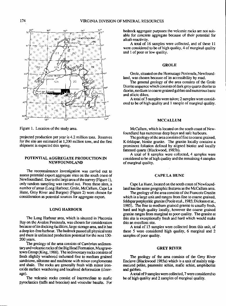
2M NEtFOUilo{-AltD
an ' ho nyoL,--*---To
r74 VIRGINIA DIVISION OF MINERAL RESOURCES
Figure l. Location of the study area.
projected production per year is 4.2 million tons. Reservesfor the site are estimated at 1,200 million tons, and the firstshipment is expected this spring.
POTENTIAL AGGREGATE PRODUCTION INNEWFOTJNDLAND
The reconnaissance investigation was carried out toassess potenfql export aggregate sites on the south coast ofNewfoundland. Due to the large areaof the survey (Figure 1),only random sampling was carried ouL From these sites, anumber of areas (-ong Harboul, Grole, McCallum, Cape LaHune, Grey River and Burgm) (Figure 2) were chosen forconsideration as potential sources for aggregate exporl
LONG HARBOUR
The Long Harbour area, which is situated in PlacentiaBay on the Avalon Peninsula, was chosen for considerationbecause ofits docking facilities, large storage area, and it hasa deep ice-free harbour. The bedrock passed all physical testsand there is unlimited production potential for the next 150-200 years.
The geology of ttre area consists of Cambrian sedimen-taryandvolcanicrocksof the BigHeadFormation, Musgrave-town Group (King, 1988). The sedimentary rocks consists offresh slightly weathered indurated fine to medium grainedsandstone, siltstone and mudslone with minor conglomerateand shale. The rocks are generally fresh with minor iron-oxide surface weathering and localized deformation (cleav-age).
The volcanic rocks consist of intermediate to maficpyroclastics (tuffs and breccias) and vesicularbasalts. For
bedrock aggregate purposes the volcanic rocks are not suit-able for concrcte aggregate because of their potential foralkali-reactivity.
A otal of 16 samples were collected, and of these 1lwere considered to be of high quality,4 of marginal qualityand 1 ofpoor or low quality.
GROLE
Grole, situated on the Hermatage Peninsula, Newfound-land, was chosen because of its accessibility by road.
The general geology of the area consists of the GroleDiorite sequence which consists of dark $ey quartz diorite todiorite, medium to coarse grained gabbro and numerous basicand silicic dikes.
A toal of 3 samples were taken; 2 samples were consid-ered to be of high quality and I sample of marginal quality.
MCCALLI.]M
McCallum, which is located on the south coast of New-foundland has numerous deep bays and safe harbours.
The geology of the area consists of fine to coarse grained,K-feldspar, biotite granite. The granite locally contains aprominent foliation defined by aligned biotite and locallyfattened quartz (Blackwood, 1985b).
A total of 8 samples were collected,4 samples wereconsidered to be of high quality and the remaining 4 samplesof marginal quality.
CAPE LA HI.JNE
Cape La Hune, located on the south coast of Newfound-land has the same geographic features as the McCallum area.
The geology of the area consists of the Francois Granitewhich is a large unit and ranges from fine to coarse grained,feldsparporphyritic granite @ooleetal., 1985; Dickson etal,1985). The fine to medium grained granite is usually fresh,hard and high quality locally, however the coarse grainedgranite ranges from marginal to poor quality. The granite atthis site is exceptionally fresh and hard which would makethis an excellent site.
A total of 13 samples were collected from this unit, ofthese 5 were considered high quality, 6 marginal and 2samples of poor quality.
GREY RIVER
The geology of the area consists of the Grey RiverEnclave @lackwood 1985a) which is a unit of mainly mig-matized pelite, psammite schist, mafic schist, amphiboliteand gabbro.
A total of 9 samples were collected, 7 were considered obe of high quality and 2 samples of marginal quality.
6o"
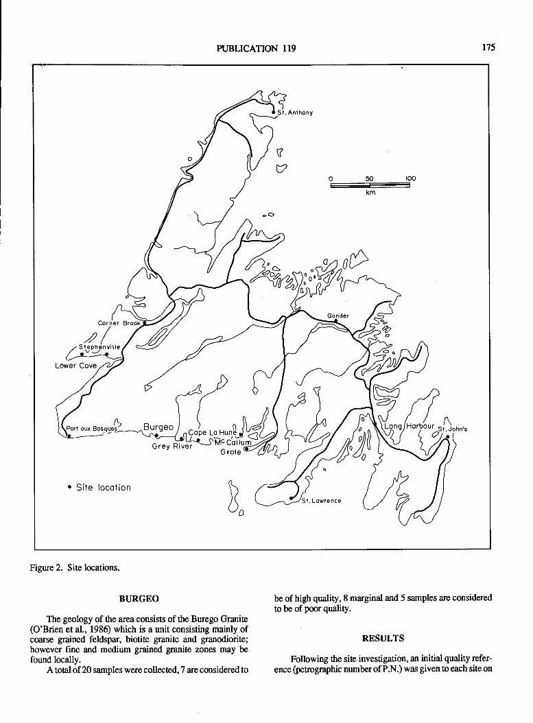
PUBLICATION II9 175
o 50 loo
--
KM
ODa'o^r0
Lower Cove
/Lt oux Bosque'gl
. Sile locotionn
)(\./D
l. Lowrence
Corner
s(nlnuiue
Figure 2. Sile locations.
BURGEO
The geology of the area consists of the Burego Granite(O'Brien et al., 1986) which is a unit consisting mainly ofcoarse grained feldspar, biotite ganite and granodiorite;however fine and medium grained granite zones may befound locally.
Atotal of 20 samples were collected, T are considered to
be of high quality, 8 marginal and 5 samples are consideredto be of poor quality.
RESULTS
Following the site investigation, an initial quality refer-ence (petrographic numberof P.N.) was given to each site on
r76 VIRGINIA DIVTSION OF MINERAL RESOI.]RCES
the following considerations. The rock types were rated onthe basis of the amornt of deleterious substances present andtlre perographic number.
Deleterious substances are materials that occur in or onrocks and are capable of producing adverse effects; e.g.,chemical reactions with other minerals resulting in a deterib-ration of the rock or cement binder used in concrete or asphalt.Some common deleterious substances include clays, organicmatlgr, mica, iron and manganese oxide staining and chertyor fine grained siliceous material. alteration zones, encrusta-tions and the &gree of weathering are also factors consideredto be delirious to the rock.
The penographic number was calculated for each siteand this measuredthe initial quality of material foraggregatepurposes. The perographic number is calculated by sam-pling 100 clasts or rock fragments and assigning a petrogra-phic frcto to each clast u fragment. The perographicfactors range from I (best) o 10 (worst) depending on iocktypes, weathering, and hardening. Each clast is given aperographic factor of l, 3,6 and 10 (Canadian SnndardsAssociation, 1973; Table l). A modified petrographic seriesof factms (from Bragg, 1986) is given in table-2. Thesefactors provide an initial assessment of the rocks for aggre-gate use. The penographic number of a rock is the sum of thepetrographic factors for 100 clasts orrock fragments and thuscan range between 100 and 1000. The perographic fxtorlnumber is usually affected by the degree of weathering (Table3). Table 4 shows the petrographic number ranges oi differ-entrock units found in the study area.
Table 5 shows the initial assessment of the quality of thedifferent rock groups based on field observations and perographic number. The Burgeo, Francois and McCallurngran-ites and the gabbros of the Grey River Enclave are allconsidered to be of high potential for concrete aggregatbQable 4) and should be investigated further. The majoriiy ofsamples (50) came from these units, and 23 samples wereconsidered tobeof high potential (P.N. I l0-130),20 samplaswere considered to be marginal quality (p.N. 150-200) andonly 7 samples, 5 of which were Burgeo granite, wereconsidered pou quality (P.N. 215-300).
Of the26 samples taken from theBayd' Espoirmeasedi-ments and theGaultois granite, only I sample of the measedi-ments is considered high quality (P.N. 110), 5 samples areconsidered marginal (P.N. 155-200) and the remainder 12samples are considered to be of poor quality (p.N. 225ffi).
Table 6 grves the results of detailed testing of represen-tative samples from each gfoup or formation.
CONCLUSION
Wittr its geographic location, deep and ice free bays,unlimited production potential, minimal land use conflicts,low cost of shipping and results from initial and selectivedetailed testing shows the Newfoundland's south coast to beof high potential for concrete aggegate supplier for export.
ACKNOWLEDGEMENTS
The author wishes to thank Mr. Lloyd St. Croix forproviding capable, cheerful and interesting assisance. Mr.I:wson Dickson, who mapped the area is thanked for hisassistance and interpretation of the geology.
REFERENCES CITED
Blackwood, R.F., 1985a, Geology of the Grey River area,southwest coast of Newfoundland: in Current Research.Newfoundland Department of Mines and Energy, MineralDevelopment Division, Report 85-1, p. 153-16/.
Blackwood, R,F., 1985b, Geology of tte Facheux Bay area(llPB), Newfoundland Deparrnent of Mines and Energy,Mineral Development Division, Report 854, 56 p.
Bragg, D., 1986, Reconnaissance snrdy of bedrock aggegatepotential foroffshore and industrial use: in CurrentResearch.Newfoundland Department of Mines and Energy, MineralDevelopment Division, Report 86-1, p. 297-301.
Canadian Standards Association 1973: CSA standard423.2.30, Rexdale, Ontario, p. 207 -209.
Dickson, W.L., Delaney, P.W., and Pmle, J., 1985, Geologyof the BurgeoGranite and associatedrocks in theRameaandIa Hune areas, southern Newfoundland, in Current Re-search. Newfoundland Department of Mines and Energy,Mineral Development Division, Report 85-1, p. L37-l4F'.
King, A.F., 1988, Geology of the Avalon Peninsula, New-foundland (pars of lK, lL, lM, and 2C): NewfoundlandDepartrnentof Mines, Mineral Development Division, Map88-01.
O'Brien, S.J., Dickson, W.L., and Blackwood, R.F., 1986,Geology of the central portion of the Hermitage Flexure area,Newfoundland: in Current Research. Newfoundland Depart-ment of Mines and Energy, Mineral Development Division,Report 861, p. 189-208.
Poole, J., Delaney, P.W., and Dickson, W.L., 1985, Geologyof the Francois Granite, south coast of Newfoundland: lzCurrent Research. Newfoundland Department of Mines andEnergy, Mineral Development Division, Report85- l, p. 145-r52.
PUBLICATION II9
WEST VIRGINIA'S NONFUEL MINERAL RESOURCES
Claudette M. SimardWest Virginia Geological and Economic Suney
P.O. Box 879Morgantown, WV 26505-0879
177
INTRODUCTION
Nonfuel minerals are some of West Virginia's mostimportant products. They are essential raw materials for theState's construction, chemical, manufacfirring, agricultural,and mining industries. West Virginia's most significant non-fuel minerals, in order of tonnage produced, include lime-stone and dolomite, sand and gnvel, sandstone, salt, and clayand shale. In 1988, about 15 million short lons ofnonfuelminerals valued atabout$ 150 million wereproduced in WestVirginia.
GEOLOGIC SETTING
The geology of the state plays an important role in thetype, availability, and location of West Virginia's nonfuelmineral resources. Most of West Virginia's bedrock is sedi-mentary except for small areas of igneous and metamorphicrocks in some of the extreme eastern counties. The State isdivided physiographically by the Allegheny Front into twoareas: the eastern Valley and Ridge Province and the westernAppalachian Plateau Province (Figure 1). The Valley andRidgeincludes olderrockunits from Cambrian ttnough Mis-sissippian age which outcrop as narrow northeast-southwestrrending bands. The Appalachian Plateau is comprised ofgenerally younger rock, Mississippian o Permian in age,which crop out as wide, arcuate bands subparallel o theValley and Ridge ourcrops. In general, all of the rock unitsthicken southward and eastward (Price and ottprs, 1938).
Quaternary alluvial and lake deposits occur in major sEeamvalleys.
The easlern third of West Virginia is in ttre Valley andRidge Physiographic Province (Figure 1). The Valley andRidge is characterized by tightly folded and sometimesfaulted srucfirres eroded to subprallel valleys and ridgestrending northeast- southwesl As a result of intense foldingand faulting, beds commonly dip steeply and crop out as
parallel belts of rock sequences which may be repeatedseveral times. Ridges are generally capped by resistant sand-stones, and the intervening valleys are of soluble limestones
and easily eroded shales. The oldest units, Cambrian in age,
are fornd in the eastemmost counties in the Great Valleysection of the Valley and Ridge. Ordovician, Silurian, De-voniaru and Mississippian-age units crop outin ttre remainderof the Valley and Ridge.
The western two-thirds of WestVirginia is in the Appa-lachian Plateau Province (Figure l). Younger sedimenc ofthe Appalachian Plateaus were deposited in the DunkardBasin over the older units now exposed in the Valley andRidge. Rock strata are relatively flat- lying with a gentle
regional dip toward the basin's cent€r in northwestern West
Virginia. A band of the oldest units of the AppalachianPlateaus, Mississippian limestones, sandstones, and shales,
rim the basin's edge at the Allegheny Fronl Farther west,
Pennsylvanian cyclic sequerrces of sandstone, shale, clay,limes0one, and coal deposited in deltaic and alluvial fan en-
vironments, crop out in a wide band that encompasses almost
50Vo of. the State. tn northwestern West Virginia, rock units
similar to the Pennsylvanian sequences but with more shales
and thinner limestones and coals are believed to be Permianin age.
The Allegheny Mountain Section of the AppalachianPlateau, located at the base of the eastern panhandle, includes
stnrcturally conrolled open folds. Erosion of these open
folds has exposed Mississippian and Devonian units in the
midstof youngerPennsylvanian strata. As aresult, economi-cally imporant Mississippian limestones are exposed innorthern Wast Virginia.
Quatemary alluvial and lakedeposits also occuron many
of the major rivers in West Virginia. The western border ofthe Sate , the Ohio River, contains up to 145 feet of sand and
gravel outwash from Pleistocene glacien in neighboringFennsylvania and Ohio. The sand and gravel is located innested terraces, floodpliains, and in the river channel. Quater-nary clay deposits also occur in the Ohio River Valley' the
Monongahela and Potomac River valleys, and in the aban-
dornd Teays Valley (Figure 1).
CONSTRUCTION AGGREGATE
Consrucdon aggegate is West Virginia's major non-
fuel commodity in terms of production value and tonnage. Ofover 14 million tons of limestone, dolomite, sand and gravel,
and sandstone quanied in the State during 1988, almost I 1.5
million lons wereprocessed fc aggregate. Thattonnage was
valued atabout $46 million, equalling almostone-third of the
State's total value of nonfuel mineral production. Aggregatehas a wide variety of applications in construction including
use in concrete, asphalt, as railroad ballast, road base, and fill.Limestorrc and dolomite are West Virginia's leading con-
stnrction aggregales followed by sand and gnvel, and sand-
stone. Artificial construction aggregate produced in the State
includes slag and ash from coal-fired power plants.
West Virginia can be roughly divided ino tlree aggregateproducing regions, based on geology.Ohio River sand and
gravel is produced in the westem part of he State; sandsonein ttre center; ard limestone in eastern West Virginia. The
type of aggregate used fc a construction project pq:tiallrdebnds on local geology because agpgate is a high-vol-ume, low-value commodity that is expensive to transporl At
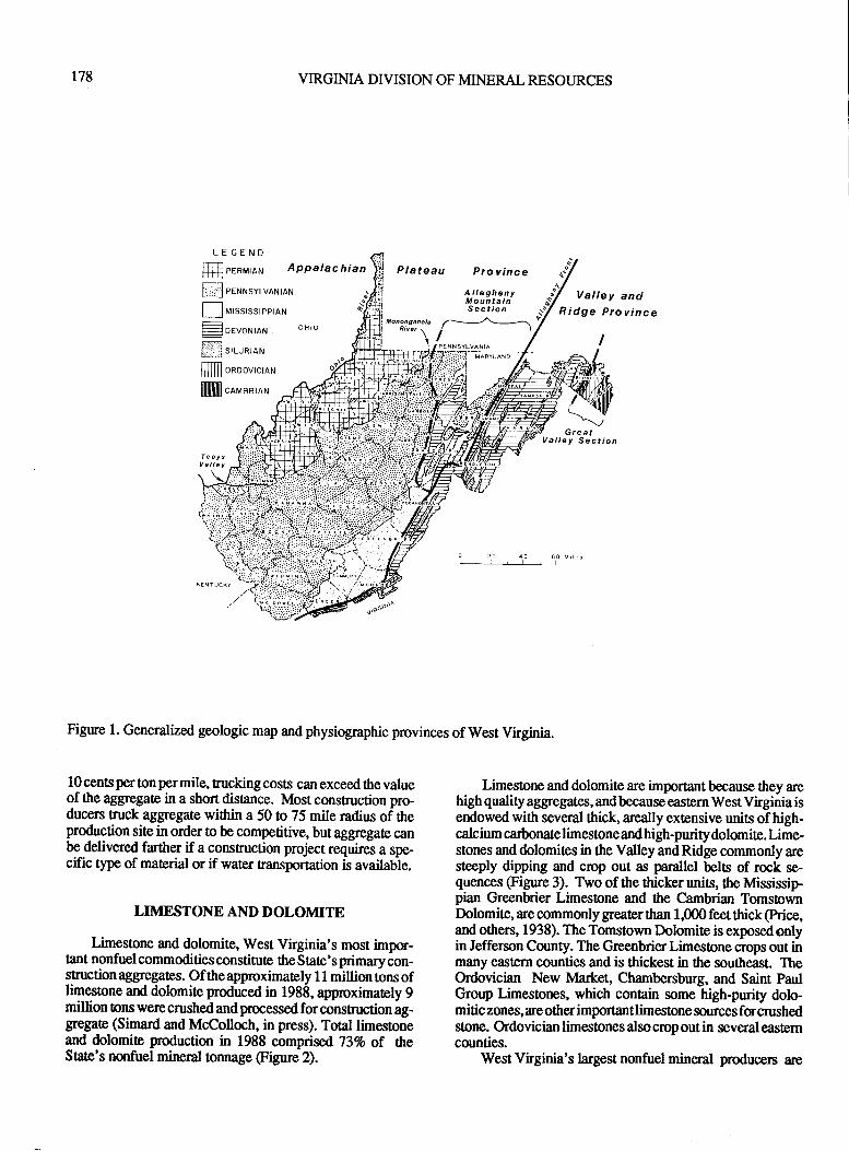
178 VIRGINIA DIVISION OF MINERAL RESOURCES
Plateau Province
Valley andR idge Province
Limes0one and dolomite are important because they arehigh quality aggregates, and because eastern West Virginia isendowed with several thick, areally extensive units of high-calcium carbonate limestone and high-purity dolomite. Lime-stones and dolomites in the Valley and Ridge commonly aresteeply dipping and crop out as parallel belts of rock se-quences (Figure 3). Two of the thicker units, fte Mississip-pian Greenbnier Limestone and the Cambrian TomstownDolomite, are commonly greater than 1,000 feet thick (Price,and others, 1938). The Tomstown Dolomite is exposedonlyin Jefferson County. The Greenbrier Limestone crops out inmany eastem counties and is thickest in the southeast. TheOrdovician New lvlarket, Charnbersburg, and Saint PaulGroup Limestorps, which conain some high-purity dolo-mitic zones, are other important limestone sources for crushedstone. Ordovician limestones also crop out in seve,ral easterncounties.
West Virginia's largest nonfuel mineral producers are
LEGEND
ffi ernr",,ar.r Appalac hian
ffi eeruusvrvaruraru
f-l urss,ssrc"raruF:-F- DEVONIAN
N t,.r^,on,
flfllTl oaoovrcraru
llJlllllllllll ca"'^, o,
Figure l. Generalized geologic map and physiographic provinces of west virginia.
10 cents per ton per mile, trucking costs can exceed the valueof the aggregate in a short distance. Most construction pro-ducers ruck aggregate within a 50 to 75 mile radius of theproduction site in order to be competitive, but aggregate canbe delivered farther if a constuction project requires a spe-cific type of material or if water transportation is available.
LIMESTONE AND DOLONdITE
Limestone and dolomite, West Virginia's most imptr-tant nonfuel commodities constitute the Sate's primary con-struction aggegates. Ofthe approximately I 1 million tons oflimestone and dolomite produced in 1988, approximately 9million tons werecrushed andprocessed forconstruction ag-gregate (Simard and McColloch, in press). Total limesoneand dolomite production in 1988 comprised 73Vo of heStaie's nonfuel mirpral tonnage (Figure 2).
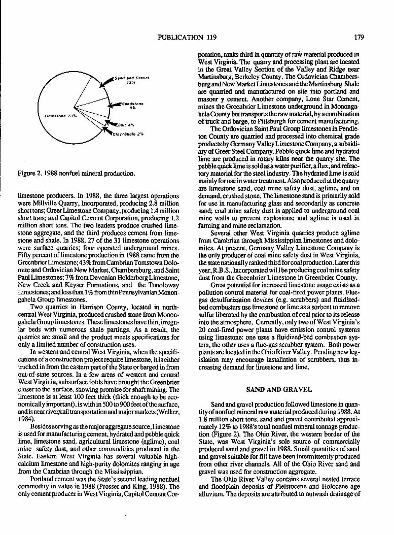
Limestone 73Y"
PUBLICATION II9 179
Figure 2. 1988 nonfuel mineral production.
limestone prodrcers. In 1988, the three largest operationswere Millville Quarry, Incorporated, prodrrcing 2.8 millionshort tons; Greer Limestone Company, producing 1 .4 millionshort tons; and Capitol Cement Corporation, producing 1.2million short tons. The two leaders produce crushed lime-stone aggegate, and ttre third goduces cement from lime-stone and shale. In 1988,n of the 3l limesone operationswere surface quarries; four operated underground mines.Fifty percent of limestone production in 1988 came from theGreenbrierlimestone; 43 7o from Cambrian Tomstown Dolo-mite and Ordovician New Market, Chambersburg, and SaintPaul Limestones; 77o from Devonian Helderberglimestone,New Creek and Keyser Formations, and the TonolowayLimestones; andless than I 7o from thinPennsylvanian Monon-gahela Group limestones.
Two quarries in }larrison County, located in north-central West Virginia, produced crushed stone from Monon-gahela Group limestones. These limestones have thin, inegu-lar beds with numerous shale partings. As a result, thequarries are small and the product meets specifications foronly a limited number of construction uses.
In western and central West Virginia, when the specifi-cations of a construction projectrequire limestone, it is eithertmckedin from the eastern partof the Stateorbargedin fromout-of-state sources. In a few areas ofwestern and cenFalWest Virginia, subsurface folds have brought the Greenbriercloser to the surface, showing promise for shaft mining. Thelimestone is at least 100 feet thick (thick enough to be eco-nomically important), is with in 500 to900 feetof the surface,andis nearriverrtail transpor0ation and majormarkets (Welker,1984).
Besides serving as the major aggrcgate source, I imestoneis used fm manufacaring cement, hydrated and pebble quicklime, limestone sand, agricultural limestone (aglime), coalmine safety dust, and other commodities produced in theState. Eastem West Virginia has several valuable high-calcium limestone and high-purity dolomites ranging in agefrom the Cambrian through the Mississippian.
Portland cement was the State's second leading nonfuelcommodity in value in 1988 (Prosser and King, 1988). Theonly cementproducer in West Virginia, Capitol CementCor-
poration, ranls ftird in quantity of raw marerial produced inWest Virginia. The quarry and processing plant are locatedin the Great Valley Section of the Valley and Ridge nearldartinsburg, Berkeley County. The Ordovician Chambers-burgandNew Marketlimestones andtheMartinsbug Shaleare quarried and manufacfired on site ino portland andmasonr y cement. Another company, Ione Star Cement,mines the Grcenbrier Limestone underground in Mononga-helaCounty but transpots theraw material,by acornbinationof tuck and barge, to Pittsburgh for cement manufacnring.
The Ordovician Saint Paul Group limestones in Pendle-ton County are quanied and processed inO chemical gradeproducts by Germany Valley Limestone Company, a subsidi-ary of Greer Steel Company. Pebble quick lime and hydratedlime are goduced in rotary kilns near the quarry site. Thepebble quick lime is sold as a water purifier, a flux, and refrac-tay material for the steel industry. The hydrated lime is soldmainly forusein watertreatmenL Alsoproduced atthequarryare limestone sand, coal mine safety dust, aglime, and ondemand, crushed stone. The limestone sand is primarily soldfor use in manufacturing glass and secondarily as concretesan( coal mine safety dust is applied 0o underground coalmine walls to prevent explosions; and aglime is used infarming and mine reclamation.
Several other West Virginia quanies produce aglimefrom Cambrian through Mississippian limestones and dolomites. At present, Germany Valley Limestone Company isthe only producer of coal mine safety dust in West Virginiathe state nationally ranked third for coal production. Later thisyear,R.B.S., Incorporatedwil lbeproducing coal mine safetydust from the Greenbrier Limestone in Greenbrier County.
Great potential for increased limestone usage exists as apollution control material for coal-fired power plants. Flue-gas &sulfurization devices (e.g. scrubbers) and fluidized-bed combusters use limestone or lime as a sorbent to removesulfur liberated by the combustion of coal prior to its releaseinto the atmosphere. Currently, only two of West Virginia's20 coal-fired power planc have emission control systemsusing limestone: one uses a fluidized-bed combustion sys-tem, the other uses a flue-gas scrubber system. Both powerplants are located in the Ohio River Valley. Pending new leg-islation may encourage installation of scrubbers, thus in-creasing demand for limestone and lime.
SAND AND GRAVEL
Sand and gravel production followed limestone in quan-tityofnonfuelmineralraw materialproducedduring 1988. At1.8 million short 0ons, sand and gravel contributed approxi-mately lLVo to 1988's total nonfuel mineral tonnage produc-tion @gure 2). The Ohio River, the western border of theState, was West Virginia's sole source of commerciallyproduced sand and gravel in 1988. Small quantities of sandand gravel suitable for fill havebeen intermittentlyproducedfrom other river channels. All of fte Ohio River sand andgravel was used for construction aggregate.
The Ohio River Valley concains several nested terraceand floodplain deposits of Pleistocene and Holocene agealluvium. The deposits are attributed to outwash drainage of
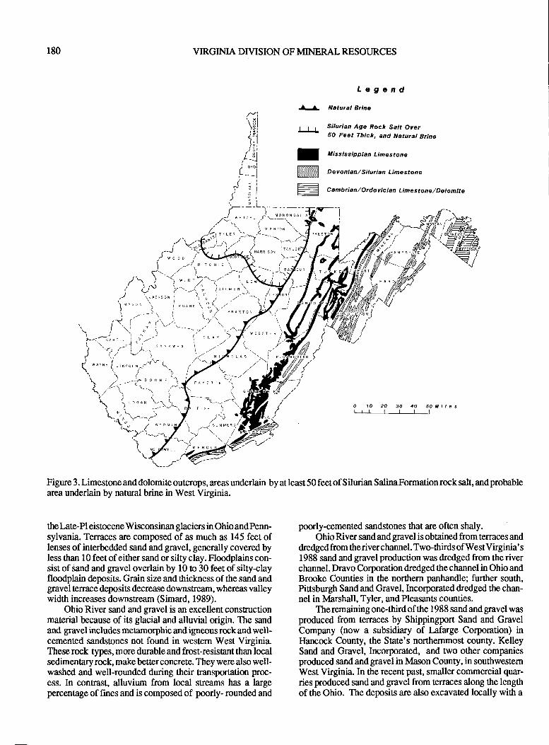
180 VIRGINIA DIVISION OF MINERAL RESOURCES
LegendNatual Brine
Silurian Age Rock Satt Oyer50 Feet Thick, and Naturc! Brine
f Mississippian Limestone
N Devonian,/siturian Limestone
Figure3.Limestoneanddolomiteoutcrops,areasunderlain byatleast50feetofSilurianSalinaFormationrocksalt,andprobablearea underlain by natural brine in West Virginia.
the Late-Pl eistocene Wisconsinan glaciers in Ohio and Penn-sylvania. Terraces are composed of as much as 145 feet oflenses of interbedded sand and gravel, generally covered byless than 10 feet of either sand or silty clay. Floodplains con-sist of sand and gravel overlain by 10 to 30 feet of silty-clayfloodplain deposits. Grain size and thickness ofthe sand andgravel terrace deposits decrease downstream, whereas valleywidth increases downstream (Simard, 1989).
Ohio River sand and gtavel is an excellent constructionmaterial because of its glacial and alluvial origin. The sandand gravel includes metamorphic and igneous rock and well-cemented sandstones not found in western West Virginia.These rock types, more dwable and frost-resistant than localsedimentaryiock, make betterconcrete. They were also well-washed and well-rounded during their transportation proc-ess. In contrast, alluvium from local streams has a largepercentage of fines and is composed of poorly- rounded and
poorly-cemented sandstones that are often shaly.Ohio River sand and gravel is obtained from terraces and
dredged from theriver channel. Two-thirds of WestVirginia's1988 sand and gnvel production was dredged from the riverchannel. Dravo Corporation dredged the channel in Ohio andBrooke Counties in the northern panhandle; further south,Pittsburgh Sand and Gravel, Incorporated dredged the chan-nel in Marshall, Tyler, and Pleasants counties.
The remaining one-third of the 1988 sand and gravel wasproduced from terraces by Shippingport Sand and GravelCompany (now a subsidiary of l,afarge Corporation) inIlancock County, the State's northernmost county. KelleySand and Gravel, Incorporated, and two other companiesproduced sand andgravel in Mason County, in southwestemWest Virginia. In the recent past, smaller commercial quar-ries produced sand and gravel from terr:rces along the lengthof the Ohio. The deposits are also excavated locally with a
-\:
\___,>/ ,,-,,\-,\\ cLAy .'r
)'u J
PUBLICATION 119 181
backhoe for fill and skid-resistance grit by city and countyhighway departments and land owners. Commercially po-duced sand and gravel is either ruckedwithin a 50 mileradiusof the operation or shipped by river barge o more distantareias.
SANDSTONE
Sandstone, a widely available source for constructionaggregate, is primarily quarried in cenfral West Virginia.Most of the State's sandstone aggegate is produced fromabundant Pennsylvanian sandstones of the Appalachian Pla-teau, but it is also prcduced from an older unit in the Valleyand Ridge. Crushed sandstone is an important aggregate fucenEal West Virginia because it is used in the region'sextensive coal mining and reclamation, and oil and gas
driltng industries, and by cities and towns for construction.Alttrough eastem limestones and western sand and gravel areconsistently of bener quality than aggregate produced frommany of the sandstone units, transportation costs into the areacan quickly exceed the value ofthe aggregate.
In 1988, 12 sandstone quarries produced about 650,000short tons of aggregate, approximately 5 percent of the totalnonfuel mineral production. The greatest amount was Fo-duced from southern and eastern areas of the AlleghenyPlateau where Pennsylvanian sandstones are massive, thick,and of higher quality than in the rest of the Sate. Almost halfof the tonnage was prodrrced in Raleigh County by RaleighStone Company from fte Upper Raleigh Sandstone, andBeckley Stone Company from the Iower Nutall Sandstone(both of the Pottsville Group).
The next three largest producen, each producing be-tween 100,000 and 50,000 tons annually, quarried the thickPenns ylvanian Conemaugh and Pottsville Group sandstonesin Preston, Tucker, and Logan Counties. In ttrc Valley andRidgehovince, asmall quarry in GrantCountyproducedlessthan 10,000ons of aggregateduring f 988 from the extremelyhard Silurian Tuscarora Formation. The remaining sandsoneaggregate producers are in cenral West Virginia where thePennsylvanian sandslones are thin, discontinuous delaic andalluvial fan deposits with numerous shale partings.In 1988,each produced less than 10,000 lons each ofrelatively poorquality aggregate suitable for fill u roadbase.
West Virginia's sandstone is equally as imporant forhigh-purity silica sand prodrrction as it is for construction ag-gregate. Minor amounts of sandstone are also quanied in theState for dimension slone. The Devonian Oriskany(Ridgeley)Sandstone, composed of well- sorted, well-rourdedgrains of at least 98% silica" is of excellent quality for ttteglass industry. U.S. Silica Company, the Sate's sole fo-ducerof silica sand, operates a quarry near Berkeley Springs,Morgan County. Their annrul production tonnage is approxi-mately equal !o the State's sandstone aggregate production.U.S. Silicaprocesses theOriskany (Ridgeley) Sandsoneinosilica sand, ground silica, and micron-sized silica mainly foruse by the glass industry. The ceramics, electronic prts, andpaint indusries, to name a few, also purchase specialty silicasand from ttre Morgan County operation. In the past, thePennsylvanian Homewoo4 Connoquenessing, and Eastlynn
Sandsones, and the Silurian Tuscaroa Sandstone were alsoquanied for glass sand.
Dimension stone, more important in the past than now,is currently produced in minor amounts fo facing as asideline to sandstone aggegate. Mazella Quarries, Incorln-rated, located in Kanawha County near Charleslon, produces
hand-hewn frcing fr,om the Pennsylvanian-age East LynnSandsone. Many of the Siate's high- quality sandstones ofall ages have been quarried in the past for use as dimensionstone.
ARTIFICIAL AGGREGATE
Artificial construction aggregate includes slag (a by-product of steel making), and fly ash ard bosom ash (coal-fired power plant waste). Slag from the Weirton SteelCompany in Weirton,Ilancock County, is sold for construc-tion aggregate ofcompanable quality to sand and gravel andcrushed stone. One company processes steel slag wlrereas
two other companies process iron blast-furnace slag. Steelslag can be used in road base, in asphalt, and as fill. hon blast-furnace slag has the same uses as steel slag and can also beused in concrete.
Fly ash can be substituted for sand and cement in con-crete producs. West Virginia's 20 coal-fired power plants,located primanily in the western half of fte State, producelarge amounts of fly ash. Considerable research and prometional effort on use of fly ash as a construction material has
been condrrcted in the past 20 years. In West Virgini4 thismaterial has been used in road construction, power plant con-stnrction, and in concrete block for several West VirginiaUniversity buildings.
SALT
West Virginia has enormous salt resources in deep rocksalt beds and in nanual brines. Most of northwestern WestVirginia is underlainby greater ttran 50 feet of rock salt of tlrcSilurian SalinaFormation (Figure 3). Depth from the surfaceto the top of the Salina varies from appnoximately 5,000 feetby ttre OhioRiveratChester,Ilancock County, to 9,000 feetat Morgantown, Monongalia County (Martens, l%3). TIteSalina Formation consists of layered beds of salt, limeslone,dolomite, and anhydrite. The individual salt beds are nevermuch more than lm feet thick and the greatest cumulativethictness of salt in one place is V10 feet in MonongaliaCounty (S mosna and others, I 977). To the south and east, theSalinaFormation gades into limestone and shale.
Commercial development of the Salina Fumation has
occurred along the Ohio River where the salt beds both attainmaximum thickness and are closest 0o the surface. Currentsalt production is in lvlarshall County (at the base of thenorthern panhandle) by PPG Indus8ies, Incorporated andLCP Chemicals-West Virginia Both companies solution-mine the top saltbed which is about lCI feet thick (ldartens,1943). Solution mining is the technique of pumping fresh wa-ter down a well into the salt fqmation and pumping the salt-sanrated solution to the surface forprocessing. Both compa-
r82 VIRGINIA DIVISION OF MINERAL RESOURCES
nies produce caustic soda and chlorine which are marketed tothe plastic, pulp and paper, metal fabricating, petroleumrefining, and rubber reclaiming industries (Prosser and King,1988).
Natural brine underlies tlp western half of ttre SAte es-peciatly in the Silurian Tuscarora Formation, the DevonianOriskany Formation, the Mississippian Greenbrier Lime-stone and Pocono Group, and the Pennsylvanian PonsvilleGroup (Price and others, 1937). Salt production from brinesfrom salt springs in Kanawha County was the first mineralindustry in the State. Later wells were drilled all over westernWest Virginia to reach deeper brines. Commercial produc-tion of the natural brine continued to boom until World WarII when the deep Salina salts were discovered and apped.Abundant natural brine resources remain.
CLAYAND SHALE
West Virginia has extensive clay and shale resources dis-tributed throughout the Sate. Principle types of clay/ shatedeposi6 that have been or are presently mined include shaleformations, coal seam underclays, and Quaternary lake andriver clays. In 1988, West Virginia had three clay/shaleproducers whose combined tonnage connibuted,2%o to WestVirginia's toAl nonfuel mineralproduction (Figure 2). Andy-ses of Statewide samples of the different fypes and ages ofclay and shale deposits show grcatpotential for use in manyceramic products including light weight aggegate (I-essingand Thomson,1973). The tests have shown that some Ordo-vician through Permian clays and shales have potential foruse as expanded aggregate.
The Ordovician Martinsburg Shale is one of the Stale'seconomically important shale formations. The MartinsburgShale is exposed in ttre folded strata of the Valley and Ridgeas steeply dipping northeast-southwest fiending bels (Figure1). The formation outcrop, occurring only in the S[aoe'seastern border counties, ranges in thickness from a fewhundred to 1,500 feet thick . The most extensive out$opsoccur in the eastern panhandle in Jeffe rson and BerkeleyCounties. Currently, the lvlartinsburg Shale is quarried neartle lown of Martinsburg, Berkeley County, forraw materialused in manufacturing cement and brick. Capitol CementCompany quarries the Martinsburg Shale and Ordovicianlimestones to produce portland and masonry cemenl
Continental Brick Company is the State's remaining producer of a once-thriving West Virginia bnick industry. Con-tinental Brick produces face brick used for buildings of alltypes. Their main market is the Washington and Baltimoreareabutbrick is shipped as faras Minnesota, New York, andVirginia. Outcrops of Devonian shale of equal or greaterthickness than the Martinsburg Shale satisfactorily test foruse in sewer pipe, building brick, face brick, and lightweightaggregate (Lassing and Thomson,197 3).
Smaller Pennsylvanian and Permian age shale units havebeen historically important raw materials for brick and stuc-tural clay products. Although they are ubiquitous in the Ap-palrchian Plateau, ttre flat-lying individual shale units arethinner and less continuous ttran the thick Ordovician orDevonian shales. Thickness of Pennsylvanian and Permian
shales range from a few feet to about 50 feet. In the past, shaledeposits of this age were used in manufacturing many kindsof products including different kinds of tile, paving block,sewer pipes, and brick.
Coal seam underclays (commonly called fireclays) areanother important, widespread resource in West Virginia.Underclays of minable thickness occur in association withmany of the State's Pennsylvanian and Permian coal seams.Cunently, thePenns ylvanian BolivarFire Clay is quarriedbythe Sanders Dummy Company in Lincoln County, southemWest Virginia. The fireclay is ground into a powder andshaped into clay dummies (the size and shape of a stick ofdynamite) for use in spacing explosive charges in blast holes.Sanders sells the dummies by the ruckload to another com-pany for resale to coal mines. Several different underclayshave historical significance in the prodrrction of numeroustypes of clay products including refuctory brick, pavingbrick, face brick, tiles, sewer pipes, and pottery.
Quaternary alluvial and lake clays also have historicaleconomic importance. Production has occurred from thelake Monongahela clays (produced primarily along theMonongahelaRiver), clays from the Ohio River Valley andsome of its tributaries, and tle abandoned Teays River Valleylake clay. These deposits were used by the once-thrivingposery, earthenware, and chinaware indusries. Today, onlyindependentpotters locally use Quatemary deposits for theircraff Great potential exists for use of these Quat€rnary clays.
SI.]MMARY
West Virginia's nonfuel minerals are vital to the S0ate'seconomy. They are essential raw materials for a wide varietyof applications in the construction, chemical, manufacturing,and coal mining indusries of the State and surrounding areas.Their otal production value annually exceeds $125 million.Great potential exists for further utilization of tle vast quan-tity and high-quality nonfuel mineral resources of ttre State.
The WestVirginia Geological andEconomic Survey hasa number of products and services available to assist indi-viduals, companies, and govemmental agencies in determin-ing location, quantity, and quality of the State's nonfuelmineral resources. Anyone interested in our publications,open-file reports, maps, data files, knowledge, and experi-enceon the nonfuel minerals of WestVirginiacan contactus.We will be hap,py to serve you.
REFERENCES SITED
Irssing, P., and Thomson, R. D., 1973, Clays of WestVirginia, Part l: West Virginia Geological Survey MRS-3,190 p.
Martens, J. H., 1943, Rock salt deposits of West Virginia:West Virginia Geological Survey Bulletin 7,67 p.
Price, P. H., Ilare, C. 8., McCue, J. 8., and Hoskins, H. A.,1937, Sdtbrines of West Virginia: West Virginia GmlogicalSurvey, v. 8,203 p.
PUBLICATION 119
Price, P. H., Tucker, R. C., and llaught, O. L., 1938, Geologyand naturd resouces of West Virginia: West Virginia Geological Survey, v. 10,462p .
Prosser, L. J., Jr., and King, H. M., 1988, We'st Virginiaminerals yearbmk U. S. Department of ttre Interior, Bureauof Mines,6 p.
Simard C. M., 1989, Geologic history of the lower terrrcesand floodplains of the upper Ohio River Valley: West Vir-ginia Geological Survey open-file repr 8903, 16l p.
Simard, C. M., and McColloch,G., 1990, 1990WestVirginiamineral indusries direcory: West Virginia Geological Sur-vey MRS-9, 194 p.
Smosha, R. A., Patclrcn, D.G., Warshauer, S. M., and Perry,W. J., Jr., 1977, Relationships benveen depositional environ-ments, Tonol oway Limestone, and distribution of evaporitesin the Salin a Formation, West Virginia ir Studies in GeologyNo. 5: American Association of Petroleum Geologists, p.r25-r43.
Welker, D., 19&4, Deep mining the Greenbrier Limestone inwestern West Virginia: West Virginia Geol. Suney Moun-tain State Geology Magazine, p.29-34.
183

184 VIRGINIA DIVISION OF MINERAL RESOURCES
PUBLICATION 119
ABSTRACTS
r85
THE ROLE OF THE U.S. BUREAU OFMINES IN THE DEVELOPMENT AND
REGULATION OFINDUSTRIAL MINERALS
Aldo F. BarsottiU.S. Bureau of Mines24AIE. Street, N.W.
Washington, D.C. 202,41
For years, ttre United States Bureau of Mines has beenthe principal agency of the federal govemment charged witltthe responsibility of collecting, analyzing, and disseminatinginformation on over 100 mineral commodities, half of whichare industrial minerals. Many of these minerals are ubiquitous in the industrialeconomy, butall arebasicraw materialsvital to major sections of our domestic economy. With anever-increasing growth in population and urban develop-ment, growing concern for rebuilding of the nation's infra-structure, major shifs in materialrequirements for changingmanufacturing and chemicals indusries, and an increasedfocus on the environment, the issues surrounding indusfialminerals have never been greater. The Bureau of Mines willcontinue to play a major and proactive role in addressingthese issues and in fostering a sound domestic mineralsindus8y.
OVERVIEW OF DEPARTMENT OFMINES, MINERALS AND ENERGY
REGULATORY PROGRAM FOR METAL/NONMETAL NOMENCLATURE
RobertE. Morganand
Gary E.BarneYVirginia Division of Mineral Mining
P.O. Box4499Lynchburg, Y tr gima V4 502
The Commonwealth of Virginia, through the Depart-ment of Mines, Minerals and Energy maintains a staff of 24Division of Mineral Mining personnel to regulate the safety,health and environmental impact of metaVnonmetal mines.This includes the certification training for mine foremen andblasters. Permits issued by this Division must be obtained byindustry prior to any mining activity. OperationaVdeveloPment plans must be filed with a permit application addressingthe safety and environmental issues for the proposed miningoperation. The subject matter of this plan may includehydrologic impact, geologic structure of the deposit and anyinherent safety cotrcerns, gnding plans including storm sur-face runoff management, mine maps, hazardous materialhandling, andtheproposedpost-mining land use. Thepermitprocess can also include$reholding of public hearings con'
cerning any application.--. d.id;t d-o"iurring
"t tining operations involving me-
dical treaEnent, lost time, serious injury or faality are inves-tigated by Division staff. Regulations concerning_ grorydc6nEol, fireprevention, airquality, explosives, mobile equip-ment, personal protection, elecFicity, and materials handlinghave been adopted. These regulations are enforced throughregular inspections made by Division personnel.-
This Deparrnentalsoadministers a stateprogram,uniquein the nation, for abandoned metaVnon-metal mines. Funds
are available to correct safety and environmental hazards leftby mining operations prior legislation o cover these respon-
sibilities.- The priority of reclamation projecc is determinedby an Orphanedland Advisory Committee saffedbyrepre--sintatives of various state agencies, state universities, citi-zens, and the mining industry.
NORTH CAROLINA INDUSTRIALMINERALS: COMMODITIES' APPLIEDMINERAL RESEARCH, REGULATION,
AND RESOURCES TO ASSISTMINERAL DEVELOPMENT
Jeffrey C. ReidNorth Carolina Geological Survey
Division of Land ResourcesDepartment of Environment, Health,
and Natural ResourcesP.O.Box27687
Raleigh, Nuth Carolin a 27 6Il -7 687
North Carolina is richly endowed with and produces asignificant amount of industial minerals. These includeclays, feldspar, gemstones, mica, pea.t sand and gravel(cohstruction and industrial), stone (crushed and dimension),talc and pyrophyllite, lithium minerals, olivine, 91d p,hoq-
phate rmk. Prodrrction was $584 million for 1989. NorthCarolina ranked 19th nationally in the output of all mineralsand llth in industrial mineral sales. The State continues tolead the nation in the output of feldspar, mica, olivine,pyrophyllite, and lithium (spodumene) and in 1989 rankedseconC in the production of common clay, crushed granite,and phosphaorock according to ttrc U.S. Bureau of Mines.
Resources for mineral exploration andbeneficiation are
diverse. The sate geological survey provides basic geologicinformation. It has a sample repository which includes drillcue, cu$ings, and geophysical borehole records. The con-tents of the repository are computer-based to make informa-tion rerieval-easier. The geological survey has a modernheavy mineral labmatory.
The North Carolina Departrnent of Commerce and
Economic Development and the Govemor's office provideinformation on business development. The Minerals Re-
search Laboratory,located in Asheville, can perform a widevariety of mineral dressing and pilot plant sudies. The
186 VIRGINIA DIVISION OF MINERAL RESOURCES
State's geogaphic information service has extensive digiraldata which is useful for siting and for environmental impactstudies.
Regulation is governed by the Mining Act, which re-qlires that a mining permit be obtained for operations largerthan one acre. The Land Quality Section of the Division ofland Resources administers the act. Also, air and waterquality permits are required from the Division of Environ-mental Managemenl
Applied minerals research is active in North Carolina.lelected projects of the North Carolina Geological Surveyinclude: high-silica resources of the Chilhowee Gt*i(westernNorth Carolina); heavy mineral investigations in thbFall Zong (in cgnjunction with planned regional geologicmapping beginning in late 1990); evaluarionof aeroradioh-efric anomalies for heavy minerals in the Inner Coastal plain;and offshore hearry- and industrial-mineral assessment instate wators. The Minerals Research Laboratory is workingon a number of indusrial-minerals beneficiatio-n projects.-- Significant economic reserves of ilmenite-bearing sandsin upland sediments along the Fall Line in North Carolinahave been discovered. At least eight exploration companiesare actively exploring and delineating this resource. Theseterrace deposis are located primarily in Northampton, Hal-ifax, and Wilson Counties. In addition to ilmenite, otherminerals of potential economic worth include leucoxene,rutile, monazite, and zircon.
A geochemical atlas of the State is in preparation. Thegeochemical atlas is based on the National Uranium Re-sources Eraluation (NURE) data. The atlas is possiblebecause North Carolina has nearly complete statewide sam-pling from that program.
The North Carolina Geological Survey is an affiliateoffice of theEarth Science Information Cenrer @SIC) whichp_rovides free searches of available aerial photography. Thedata set is maintained on CD-ROM to providarapid clientresponse. Orthophotographs are available at nominal cost.Topographic maps axe not sold but a comprchensive mapreference collection is maintained. A publication list iiavailable upon request.
U.S. GEOLOGICAL SURVEY'SMINERAL RESOURCES DATA SYSTEM
RaymondE. AmdtU.S. Geological SurveyNational Cenrer MS 920Reston, YhginiaZ2@2
TheU.S. Geological Survey (USGS) hasbeen compilingand using the Mineral Resources Data System (MRDS) fornearly 20 years. The MRDS consists of a minerals site file,ttematic data files, and public information reference file,s. Itserves as an essential repository of metallic and indusnialminerals deposit and occurrence information for use in min-eral-resource assessments, national and international, and asa source of mineral information for the public.
The MRDS data is collected and used as an essentialbuildingblock in USGS mineral-resource s&dies and assess-ments. The MRDS data base supports National Mineral
Resource Assessment Program (NAMRAP) activities, in-cluding regional and state-wide studies and assessments; landmanagement agency studies and assessments for administra-tive units such as national forests and wilderness study areas;and quadrangle-sized studies and assessments, often in co-operation with Sate geological surveys. MRDS data is alsocollected and used in USGS-assisted studies and assessmentsin foreign countries.
Throughout its history, the MRDS has been a source ofmineral information for the public. This role was enlarged in1988 when the USGS opened the first of four MineralInfumation Offices to provide walk-in facilities for themineral community and the general public. These officesfeanre the MRDS in a user-friendly graphics environment;this is the same system that is available for viewing at thismeeting. Tlre Mineral Information Offices provide an oppor-tunity for us to work directly with the public. The creation ofthese offices has stimulated our development of graphicscapabilities and thematic graphics data sets to enhance accessto and the interpretation of the mineral-resources informationavailable through the MRDS.
More MRDS users also means more scrutiny and feed-back concerning its daa. We recently instituted a compre-hensive data quality :tssurance initiative, which includesinsallation of a series of data completeness and accuracychecks and the designation of a MRDS data editor to coordi-nate data-quality assurance and daa-gathering activities.
The MRDS mineral sites file currently includes 85,000site recuds. Although in the past the emphasis for MRDSdata gathering has been focused on metallic mineral re-sounces, and since the early 1970s on strategic and criticalminerals, a considerable numberof records contain informa-tion on industrial mineral deposits and occurrences. In-creased gathering of indusrial minerals information reflectsourgrowing awareness of the importance of ttris sectorof theminerals industry.
DEVELOPMENTS AND OPPORTUNITIESIN INDUSTRIAL CARBONATES ON
NEWFOUNDLAND'S GREAT NORTHERNPENINSULA
Ambrose F. HowseNewfoundland Deparrnent of Mines and Energy
P.O. Box 8700St. John's, Newfoundland AIB 4J6
White, high purity marble deposits with potential fu useas premium grade indusrial filler have been identified on theGreat Northern Peninsula by the Newfoundland Departmentof Mine,s. The marble occurs along a metamorphosed belt ofIower Or&vician carbonate rocks that structurally underliethe llare Ray Allochthon. The high degree of purity andbrightrrcss of the marble, and itsproximity to deep waterportshave attracted the attention of developen. Current activitiesinclude diamond drilling and bulk sample testing.
The Iower Orrdovician, carbonate platform rocks of $reGreat Northern Peninsula also host large deposits of dolo-mitic and limestone. heliminary tests on dolomite near Port
PUBLICATION 119 187
aux Choix and Cape Norman show thatit may be of metallur-gical grade. The carbonate sequences also host large depositsof limestone on tidewater that have yet to be assessed.
DIMENSION STONE INNBWFOUNDLAND
James R. MeYerNewfoundland Deparnnent of Mines and Energy
P.O. Box 8700St. John's, Newfoundland AIB 4J6
Exploration for dimension stone in Newfoundland andl^abrador is on the upswing. There are no commercialoperations at present, but megacrystic pink granite tiles wererecently installed at the new Earth Science building atMemorial University in St. John's, and interest in the availa-bility of this sone has followed. Considerable efforthasbeendirected towards locating a suitable quarry site in a large bodyof fine-grained gabbro, a "black granite" virtually identical tothe South African "Britts Blue". Examination of a variety ofpink, red, green and grey granites, as well as black and whitemarbles, continues. In Labrador interest is focused on me-dium- to coarse-grained anorthosites composed of chatoyantlabradorite crystals.
Despite intermittent production over the last 140 years,
renewed development of the province's high quality slatereserves is now imminent. Current negotiations are aimed ata redevelopment of an old slate quarry at Nut Cove, and thedevelopment of a new quarry at Keels. Both of these depositsoccur in the Cambrian aged slate in Eastern Newfoundland,which hosts green, prrple, and red slate deposits.
1991FORUM ON THE GEOLOGY OFINDUSTRIAL MINERALS:
ALBERTA/BRITISH COLUMBIA,CANADA
Wylie N. llamiltonAlbertia Geological SurveYAlberta Research CouncilP.O. Box 8330, Station F
Edmonton, Alberta, CanadaT6H 5X2
and
Z. DannY HoraBritish Columbia Geological Survey
Parliament BuildingsVictoria, British Columbia, Canada V6V 1X4
The 27th Forum on the Geology of Indusrial Mineralswill be held in Banff, Alberta, Canada in early lvlay of 1991,hosted jointly by the provinces of Alberta and British Colum-bia. Banff, an internationally famous resort town in the
Canadian Rockies, adjoins regions of both provinces richlydeveloped in indusrial mineral resources. The meeting willcompriisenvodays of technical sessions andtrvo fie1dtips tovisit-some unique mineral operations in each province. The
firstfield rip is aone-day excursion in the Bow V-alley region
of Alberta scheduled between the npo days of talks. Thesecond is a two-day rip following the talks (with an gPtig1tql
one-day extension), in the gast Kootenays region of BritishColumbia.
The Bow Valley rip will visitoperations representative
of Alberta's major industrial mineral prodrrcts; sulphur,limestone (cement and lime), and aggregate. Sulphur exmac-
tion from natural gas is conducted at Shell Canada's JumpingPound gas plant" where 600 tpd are recovered from sour gas
produced from Mississippian reservoir strata at depths below2950 m (9000 ft.). This plant is one of more than 50 ttrat make
Alberta ihe world's leaderin sulphurproduction from hydrocarbon sources. Limestones are quarried by I-afarge Canada
Inc. and Continental Lime Ltd. for cement and lime produc-tion respectively. The quanies are uniquely {ev9lop9{ inscenic mountain settings, in steeply drpping beds of De-vonian and Mississippian carbonate formations" Lafarge'solant site at Exsha* is also the location of the calciningiacility for Baymag's magnesite quarry production in BritishColumbia. The aggregate operation of Burnco Ltd. is amajor-scale working of alpine outwash gravels, which are
65im (20Cr ft.) thick in the Bow Valley and ar, e deposition-ally unique. Another possible stop is a small-stone qxq-ry
wtrictr pioduces "Rundlestone", the characteristic buildingstorrc oT Banff (including Banff Springs Hotel-the Forummeeting site).
ttie Eajt foo@nays trip will focus on several of BritishColumbia's important indusftial mineral products: magne-
site, silica, gypsum, limestone/dolomite, and dimension stone.
Magnesite is quarriedby Baymag Mines Co. Ltd' from ahugedefrsit at Mount Bmssilof, tho largest andpurestPaglsiledeiosit known in North America. Host unit is the MiddleCamUrian CathedralFormation, a thick (370 m) dolomite unitin which magnesite forms massive lenticular beds up to 100
m thick. Silica quarrying occun at two localities near
Golden, in the Ordovician Mount Wilson Quartzite. Moun-tain MineralsLtd. quarries afriablephase of ttre quartzite for-mation for processing ino a glass-grade silica sand" BertMiller Construction Ltd. quanies massive quartzite for a
lump silica product. Gypsum is quanied by Wesroc Indus-tries near Windermere and by Domtar Construction Materialsnear Canal FXats. Both quarrying operations are in sronglydisturbed, steeply dipping beds of the host evaporite unit, the
Devonian Burnais Formation, givingrise to some spectaculargypsum exposures.-- - An optional extension to the East Kootenays trip willexamine limestone/dolomite fine-grinding operations near
Creslon, where International Marble and Stone Companyproduces white calcium carbonate filler and various crushed-and
sized white rock products, from Lower Cambrian lime-store anddolomite formations quarried in the area also in the
area, Kootenay Slone Center quarries a Lower Cambrianquartzite for use as flagstone. The return journey {"oog!tCrowsnestPass to Calgary includes apossible stop at SummitLime Works' unique quairying and vertical kiln operations.

188 VIRGINIA DIVISION OF MINERAL RESOURCES
Related Documents