Magnet-less Non-reciprocal Metamaterials with Magnetic or Electric Gyrotropy Toshiro Kodera #1 , Dimitrios L. Sounas ∗2 , Christophe Caloz ∗3 # Department of Electrical Engineering, Yamaguchi University, Ube, 7558611 Japan 1 [email protected] ∗ Department of Electrical Engineering, ´ Ecole Polytechnique de Montr´ eal, Montr´ eal, QC, H3T 1J4 Canada 2 [email protected] 3 [email protected] Abstract—Two magnet-less non-reciprocal metamaterials with magnetic or electric gyrotropy are presented. Both are based on the traveling-wave resonance of transistor-loaded rings, ac- companied by rotating magnetic or electric dipole moments. Their gyrotropic properties are validated by measuring Faraday rotation of a wave reflected by or transmitted through them. I. I NTRODUCTION Magnetic gyrotropy is the key phenomenon enabling non- reciprocal devices, such as isolators and circulators, which are ubiquitous in communications systems. At microwave frequencies, ferrites have been the essential commercial gy- rotropic materials since the 1950’s, due to their high-power capability and operation stability [1] and due to the absence of alternatives. However, ferrites require a static magnetic field for biasing bias. This field is usually produced by a permanent magnet, which results in bulky components, high fabrication cost and upper-frequency limitations for resonant-type devices. The letter presents two recently introduced metamaterial structures that provide non-reciprocal gyrotropy without fer- rites and without magnets. We refer to these metamaterials as magnet-less non-reciprocal metamaterials (MNMs). The first one exhibits magnetic gyrotropy via the traveling-wave resonance of transistor-loaded microstrip-line ring resonator particles [2], where rotating magnetic dipole moments mimic the operation of a biased ferrite. This artificially created mag- netic gyrotropy is validated through reflection-type Faraday rotation (or magneto-optic Kerr effect). The second structure exhibits electric gyrotropy via the traveling-wave resonance of transistor-loaded slot-ring resonator particles[3], where rotating electric dipole moments mimic cyclotron orbits in plasmas. In contrast, to the magnetically gyrotropic struc- ture, the electrically gyrotropic structure is electromagnetically transparent, thus providing transmission-type Faraday (real Faraday) rotation, also verified experimentally. II. MAGNETICALLY GYROTROPIC TRAVELING- WAVE MICROSTRIP- LINE RING RESONATOR PARTICLE A. Principle Figure 1 shows the principle of the magnetic magnet-less non-reciprocal metamaterial (M-MNM). Magnetic moment precession associated to electron spin precession in a ferrite material, illustrated in Fig. 1(a), is mimicked by a microstrip- line ring resonator loaded by a unilateral element, as depicted in Fig. 1(b). This results in a traveling-wave resonance, as shown in Fig. 1(c), where the electrical circumference of the ring is a multiple of 2π but where the wave is traveling (as opposed to standing) due to the presence of the unilateral element. The corresponding magnetic dipole moment rotation is illustrated in Fig. 1(d). (b) dielectric substrate conducting ground plane conducting ring resonator z isolator (a) electron z t = t 0 t = t 0 +T/4 t = t 0 +T/2 t = t 0 +3T/4 H E E ring resonator θ ideal isolator z θ t = t0+T/2 2π 0 Ez t = t0+T/4 traveling-wave resonance t = t0 π 3π/2 π/2 t = t0+3T/4 0 x y z (c) (d) H E E H H H H H H E E E E Fig. 1. Principle of the magnet-less non-reciprocal metamaterial providing magnetic gyrotropy (M-MNM). (a) Rotating magnetic moment in a ferrite. (b) Rotating magnetic moment in the proposed M-MNM structure, corresponding to the local rotating electromagnetic field of the traveling-wave resonance. (c) Time evolution of the electric field along the ring resonator at four quarter- period spaced time instants for a ring loaded with an ideal isolator. (d) Elec- tromagnetic field between the ring and the ground plane and corresponding effective magnetic moment at the time instants of Fig. 1(c). B. Prototype Figure 2 shows an M-MNM prototype based on the princi- ple in Fig. 1. The structure consists of two dielectric layers and three metallic layers, where the former two are used as sub- strates. The top layer consists of the FET-loaded microstrip- Copyright 2013 IEICE Proceedings of the "2013 International Symposium on Electromagnetic Theory" 23AM1C-06 397

Welcome message from author
This document is posted to help you gain knowledge. Please leave a comment to let me know what you think about it! Share it to your friends and learn new things together.
Transcript
Magnet-less Non-reciprocal Metamaterialswith Magnetic or Electric Gyrotropy
Toshiro Kodera #1, Dimitrios L. Sounas ∗2, Christophe Caloz ∗3
# Department of Electrical Engineering, Yamaguchi University, Ube, 7558611 Japan1 [email protected]
∗ Department of Electrical Engineering, Ecole Polytechnique de Montreal, Montreal, QC, H3T 1J4 Canada2 [email protected] [email protected]
Abstract—Two magnet-less non-reciprocal metamaterials withmagnetic or electric gyrotropy are presented. Both are basedon the traveling-wave resonance of transistor-loaded rings, ac-companied by rotating magnetic or electric dipole moments.Their gyrotropic properties are validated by measuring Faradayrotation of a wave reflected by or transmitted through them.
I. INTRODUCTION
Magnetic gyrotropy is the key phenomenon enabling non-reciprocal devices, such as isolators and circulators, whichare ubiquitous in communications systems. At microwavefrequencies, ferrites have been the essential commercial gy-rotropic materials since the 1950’s, due to their high-powercapability and operation stability [1] and due to the absenceof alternatives. However, ferrites require a static magnetic fieldfor biasing bias. This field is usually produced by a permanentmagnet, which results in bulky components, high fabricationcost and upper-frequency limitations for resonant-type devices.
The letter presents two recently introduced metamaterialstructures that provide non-reciprocal gyrotropy without fer-rites and without magnets. We refer to these metamaterialsas magnet-less non-reciprocal metamaterials (MNMs). Thefirst one exhibits magnetic gyrotropy via the traveling-waveresonance of transistor-loaded microstrip-line ring resonatorparticles [2], where rotating magnetic dipole moments mimicthe operation of a biased ferrite. This artificially created mag-netic gyrotropy is validated through reflection-type Faradayrotation (or magneto-optic Kerr effect). The second structureexhibits electric gyrotropy via the traveling-wave resonanceof transistor-loaded slot-ring resonator particles[3], whererotating electric dipole moments mimic cyclotron orbits inplasmas. In contrast, to the magnetically gyrotropic struc-ture, the electrically gyrotropic structure is electromagneticallytransparent, thus providing transmission-type Faraday (realFaraday) rotation, also verified experimentally.
II. MAGNETICALLY GYROTROPIC TRAVELING-WAVEMICROSTRIP-LINE RING RESONATOR PARTICLE
A. Principle
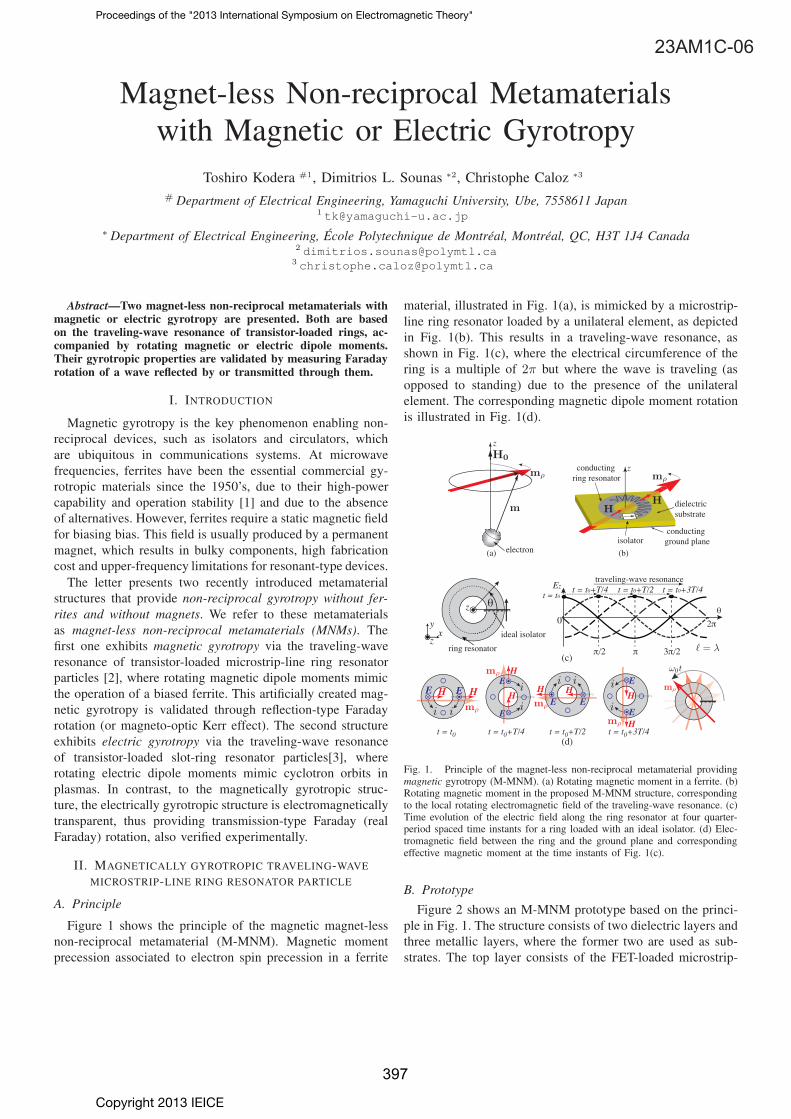
Figure 1 shows the principle of the magnetic magnet-lessnon-reciprocal metamaterial (M-MNM). Magnetic momentprecession associated to electron spin precession in a ferrite
material, illustrated in Fig. 1(a), is mimicked by a microstrip-line ring resonator loaded by a unilateral element, as depictedin Fig. 1(b). This results in a traveling-wave resonance, asshown in Fig. 1(c), where the electrical circumference of thering is a multiple of 2π but where the wave is traveling (asopposed to standing) due to the presence of the unilateralelement. The corresponding magnetic dipole moment rotationis illustrated in Fig. 1(d).
(b)
dielectricsubstrate
conductingground plane
conducting ring resonator
z
isolator
(a) electron
z
t = t0 t = t0+T/4 t = t0+T/2 t = t0+3T/4
HEE
ring resonator
θ
ideal isolator
z θ
t = t0+T/2
2π0
Ez t = t0+T/4traveling-wave resonance
t = t0
π 3π/2π/2
t = t0+3T/4
0x
y
z
(c)
(d)
HE
E
H
HH H
H
H
E
EEE
Fig. 1. Principle of the magnet-less non-reciprocal metamaterial providingmagnetic gyrotropy (M-MNM). (a) Rotating magnetic moment in a ferrite. (b)Rotating magnetic moment in the proposed M-MNM structure, correspondingto the local rotating electromagnetic field of the traveling-wave resonance. (c)Time evolution of the electric field along the ring resonator at four quarter-period spaced time instants for a ring loaded with an ideal isolator. (d) Elec-tromagnetic field between the ring and the ground plane and correspondingeffective magnetic moment at the time instants of Fig. 1(c).
B. Prototype
Figure 2 shows an M-MNM prototype based on the princi-ple in Fig. 1. The structure consists of two dielectric layers andthree metallic layers, where the former two are used as sub-strates. The top layer consists of the FET-loaded microstrip-
Copyright 2013 IEICE
Proceedings of the "2013 International Symposium on Electromagnetic Theory"
23AM1C-06
397
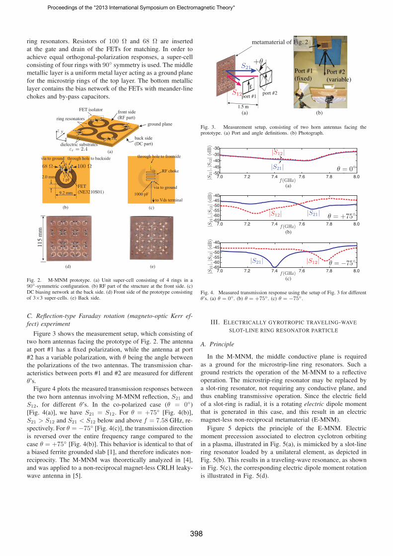
ring resonators. Resistors of 100 Ω and 68 Ω are insertedat the gate and drain of the FETs for matching. In order toachieve equal orthogonal-polarization responses, a super-cellconsisting of four rings with 90◦ symmetry is used. The middlemetallic layer is a uniform metal layer acting as a ground planefor the microstrip rings of the top layer. The bottom metalliclayer contains the bias network of the FETs with meander-linechokes and by-pass capacitors.
ground plane
front side(RF part)
back side(DC part)dielectric substrates
FET isolator
ring resonators
x
yz
G 10068
S
S
through hole to backsidevia to ground
1 pF
through hole to frontside
via to ground1000 pF
to Vds terminal
RF choke
(a)
(b)
FET(NE3210S01)9.2 mm
2.0 mm
(c)
D
(d)
115
mm
(e)
Fig. 2. M-MNM prototype. (a) Unit super-cell consisting of 4 rings in a90◦-symmetric configuration. (b) RF part of the structure at the front side. (c)DC biasing network at the back side. (d) Front side of the prototype consistingof 3×3 super-cells. (e) Back side.
C. Reflection-type Faraday rotation (magneto-optic Kerr ef-fect) experiment
Figure 3 shows the measurement setup, which consisting oftwo horn antennas facing the prototype of Fig. 2. The antennaat port #1 has a fixed polarization, while the antenna at port#2 has a variable polarization, with θ being the angle betweenthe polarizations of the two antennas. The transmission char-acteristics between ports #1 and #2 are measured for differentθ’s.
Figure 4 plots the measured transmission responses betweenthe two horn antennas involving M-MNM reflection, S21 andS12, for different θ’s. In the co-polarized case (θ = 0◦)[Fig. 4(a)], we have S21 = S12. For θ = +75◦ [Fig. 4(b)],S21 > S12 and S21 < S12 below and above f = 7.58 GHz, re-spectively. For θ = −75◦ [Fig. 4(c)], the transmission directionis reversed over the entire frequency range compared to thecase θ = +75◦ [Fig. 4(b)]. This behavior is identical to that ofa biased ferrite grounded slab [1], and therefore indicates non-reciprocity. The M-MNM was theoretically analyzed in [4],and was applied to a non-reciprocal magnet-less CRLH leaky-wave antenna in [5].
Port #1(fixed)
Port #2(variable)
(b)
metamaterial of Fig. 2
port #1port #2
1.5 m(a)
Fig. 3. Measurement setup, consisting of two horn antennas facing theprototype. (a) Port and angle definitions. (b) Photograph.
-50-45-40-35-30
7.6 7.2 7.4 7.0 7.8 8.0
(a)
-65-60-55-50-45-40
7.6 7.2 7.4 7.0 7.8 8.0
(b)
-65-60-55-50-45-40
7.6 7.2 7.4 7.0 7.8 8.0
(c)
Fig. 4. Measured transmission response using the setup of Fig. 3 for differentθ’s. (a) θ = 0◦. (b) θ = +75◦. (c) θ = −75◦.
III. ELECTRICALLY GYROTROPIC TRAVELING-WAVESLOT-LINE RING RESONATOR PARTICLE
A. Principle
In the M-MNM, the middle conductive plane is requiredas a ground for the microstrip-line ring resonators. Such aground restricts the operation of the M-MNM to a reflectiveoperation. The microstrip-ring resonator may be replaced bya slot-ring resonator, not requiring any conductive plane, andthus enabling transmissive operation. Since the electric fieldof a slot-ring is radial, it is a rotating electric dipole momentthat is generated in this case, and this result in an electricmagnet-less non-reciprocal metamaterial (E-MNM).
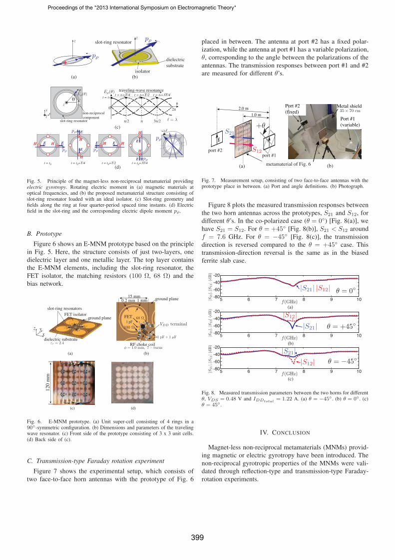
Figure 5 depicts the principle of the E-MNM. Electricmoment precession associated to electron cyclotron orbitingin a plasma, illustrated in Fig. 5(a), is mimicked by a slot-linering resonator loaded by a unilateral element, as depicted inFig. 5(b). This results in a traveling-wave resonance, as shownin Fig. 5(c), the corresponding electric dipole moment rotationis illustrated in Fig. 5(d).
Proceedings of the "2013 International Symposium on Electromagnetic Theory"
398
(b)
dielectricsubstrate
slot-ring resonatorz
isolator(a)
z
(c)
θ
slot-ring resonator
non-reciprocalcomponent
xy
z
z
ρ
θ
t = t0+T/2
2π0
t = t0+T/4traveling-wave resonance
t = t0
π 3π/2π/2
t = t0+3T/4
0
t = t0 t = t0+T/4 t = t0+T/2 t = t0+3T/4(d)
E
E
H
H
HE EH
E
E
H
H
E E HH
Fig. 5. Principle of the magnet-less non-reciprocal metamaterial providingelectric gyrotropy. Rotating electric moment in (a) magnetic materials atoptical frequencies, and (b) the proposed metamaterial structure consisting ofslot-ring resonator loaded with an ideal isolator. (c) Slot-ring geometry andfields along the ring at four quarter-period spaced time instants. (d) Electricfield in the slot-ring and the corresponding electric dipole moment pρ.
B. Prototype
Figure 6 shows an E-MNM prototype based on the principlein Fig. 5. Here, the structure consists of just two-layers, onedielectric layer and one metallic layer. The top layer containsthe E-MNM elements, including the slot-ring resonator, theFET isolator, the matching resistors (100 Ω, 68 Ω) and thebias network.
ground plane
dielectric substrate
FET isolatorslot-ring resonators
xyz
(a) (b)
68
100
100
68
GS
DS
FET1 pF
15 mm1 mm0.2 mm ground plane
RF choke coil
(c) (d)
120
mm
Fig. 6. E-MNM prototype. (a) Unit super-cell consisting of 4 rings in a90◦-symmetric configuration. (b) Dimensions and parameters of the travelingwave resonator. (c) Front side of the prototype consisting of 3 x 3 unit cells.(d) Back side of (c).
C. Transmission-type Faraday rotation experiment
Figure 7 shows the experimental setup, which consists oftwo face-to-face horn antennas with the prototype of Fig. 6
placed in between. The antenna at port #2 has a fixed polar-ization, while the antenna at port #1 has a variable polarization,θ, corresponding to the angle between the polarizations of theantennas. The transmission responses between port #1 and #2are measured for different θ’s.
Port #1(variable)
(a) (b)metamaterial of Fig. 6
Port #2(fixed)
Metal shield
port #1port #2
2.0 m
1.0 m
Fig. 7. Measurement setup, consisting of two face-to-face antennas with theprototype place in between. (a) Port and angle definitions. (b) Photograph.
Figure 8 plots the measured transmission responses betweenthe two horn antennas across the prototypes, S21 and S12, fordifferent θ’s. In the co-polarized case (θ = 0◦) [Fig. 8(a)], wehave S21 = S12. For θ = +45◦ [Fig. 8(b)], S21 < S12 aroundf = 7.6 GHz. For θ = −45◦ [Fig. 8(c)], the transmissiondirection is reversed compared to the θ = +45◦ case. Thistransmission-direction reversal is the same as in the biasedferrite slab case.
5 6 7 8 9 10
-20
-40
-60
-80
(c)
5 6 7 8 9 10
-20
-40
-60
-80
5 6 7 8 9 10
-20
-40
-60
-80
(a)
(b)
Fig. 8. Measured transmission parameters between the two horns for differentθ, VDS = 0.48 V and IDDtotal
= 1.22 A. (a) θ = −45◦. (b) θ = 0◦. (c)θ = 45◦ .
IV. CONCLUSION
Magnet-less non-reciprocal metamaterials (MNMs) provid-ing magnetic or electric gyrotropy have been introduced. Thenon-reciprocal gyrotropic properties of the MNMs were vali-dated through reflection-type and transmission-type Faraday-rotation experiments.
Proceedings of the "2013 International Symposium on Electromagnetic Theory"
399
ACKNOWLEDGMENT
This work was supported by the NSERC Discovery Accel-erator Supplement Grant # 396116-10 and by the KAKENHIGrant-in-Aid # 23686054.
REFERENCES
[1] B. Lax and K. J. Button, Microwave Ferrites and Ferrimagnetics,McGraw-Hill, 1962.
[2] T. Kodera, D. L. Sounas, and C. Caloz, “Artificial Faraday rotation usinga ring metamaterial structure without static magnetic field,” Appl. Phys.Lett., vol. 99, pp. 031114:1-3, July 2011.
[3] T. Kodera, D. L. Sounas, and C. Caloz, “Faraday Rotation by artificialelectric gyrotropy in a transparent slot-ring metamaterial structure, inIEEE APS Int. Symp., Chicago, IL, USA, July 2012.
[4] D. L. Sounas, T. Kodera, and C. Caloz, “Electromagnetic modelingof a magnet-less non-reciprocal gyrotropic metasurface,” IEEE Trans.Antennas and Propagations, in press.
[5] T. Kodera, D. L. Sounas, and C. Caloz, “Non-Reciprocal Magnet-less CRLH Leaky-Wave Antenna based on a Ring Metamaterial Struc-ture,” IEEE Antennas Wireless Propagat. Lett., vol. 10, pp. 15511554,Jan. 2012.
Proceedings of the "2013 International Symposium on Electromagnetic Theory"
400
Related Documents