Plasmonics and Metamaterials Nick Fang ME 598 © 2006-2009 Nick Fang, University of Illinois. All rights reserved. 1 Nick Fang University of Illinois [email protected]

Welcome message from author
This document is posted to help you gain knowledge. Please leave a comment to let me know what you think about it! Share it to your friends and learn new things together.
Transcript
Plasmonics and Metamaterials
Nick Fang
ME 598 © 2006-2009 Nick Fang, University of Illinois. All rights reserved. 1
Nick FangUniversity of [email protected]
Outline• Introduction to Metamaterials
• New Physics of Metmaterials– Artificial PlasmaArtificial Plasma– High Frequency Magnetism– Negative Refraction– Negative Refraction– Cloaking
• Outlook
ME 598 © 2006-2009 Nick Fang, University of Illinois. All rights reserved. 2
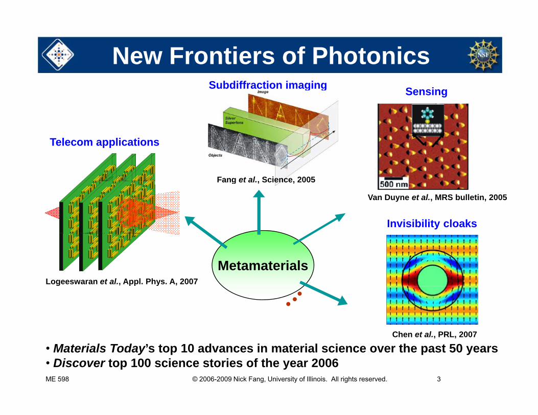
New Frontiers of PhotonicsSubdiffraction imaging Sensing
Fang et al., Science, 2005
Telecom applications
Fang et al., Science, 2005
Invisibility cloaks
Van Duyne et al., MRS bulletin, 2005
MetamaterialsLogeeswaran et al., Appl. Phys. A, 2007
Chen et al., PRL, 2007
ME 598 © 2006-2009 Nick Fang, University of Illinois. All rights reserved. 3
• Materials Today’s top 10 advances in material science over the past 50 years • Discover top 100 science stories of the year 2006
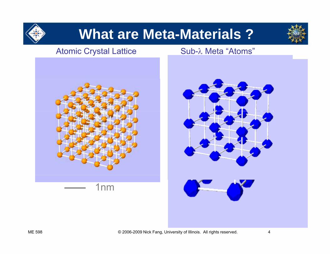
What are Meta-Materials ?Atomic Crystal Lattice Sub- Meta “Atoms”
1nm 10 nm -100 m
ME 598 © 2006-2009 Nick Fang, University of Illinois. All rights reserved. 4
Metamaterials
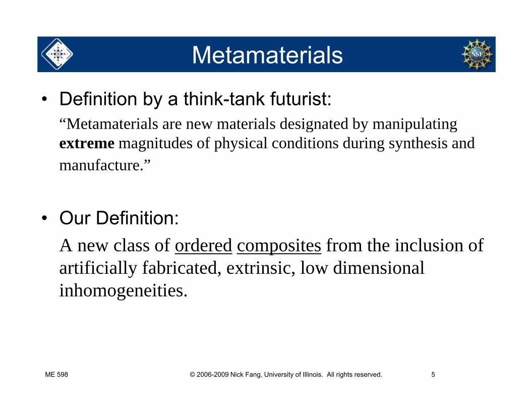
• Definition by a think-tank futurist: “Metamaterials are new materials designated by manipulatingMetamaterials are new materials designated by manipulating extreme magnitudes of physical conditions during synthesis and manufacture.”
• Our Definition:A new class of ordered composites from the inclusion of artificially fabricated, extrinsic, low dimensional inhomogeneities.
ME 598 © 2006-2009 Nick Fang, University of Illinois. All rights reserved. 5
Metamaterial vs Natural Medium
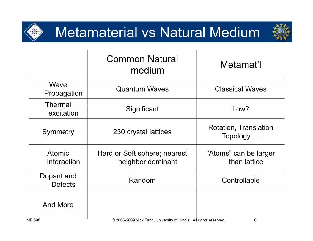
Common Natural medium Metamat’l
Wave Propagation Quantum Waves Classical Waves
ThermalThermal excitation Significant Low?
Symmetry 230 crystal lattices Rotation, TranslationTopologyTopology …
Atomic Interaction
Hard or Soft sphere; nearest neighbor dominant
“Atoms” can be larger than lattice
Dopant and Defects Random Controllable
ME 598 © 2006-2009 Nick Fang, University of Illinois. All rights reserved. 6
And More
Electromagnetic Metamaterials
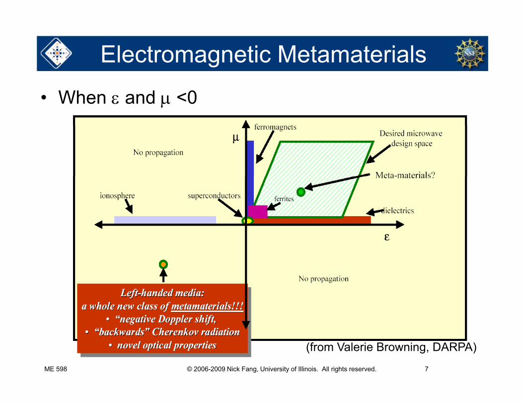
• When and <0
ME 598 © 2006-2009 Nick Fang, University of Illinois. All rights reserved. 7
(from Valerie Browning, DARPA)
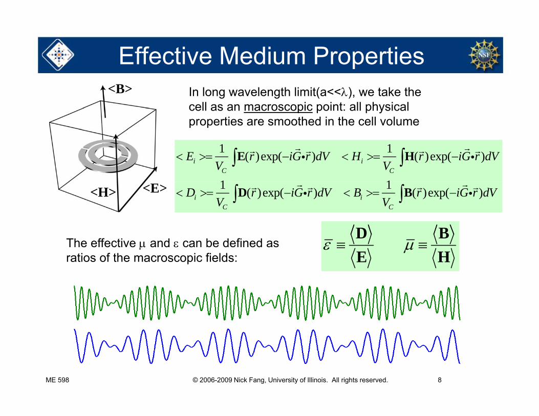
Effective Medium Properties<B> In long wavelength limit(a<<), we take the
cell as an macroscopic point: all physical properties are smoothed in the cell volume
1 1( )exp( ) ( )exp( )
1 1
i iC C
E r iG r dV H r iG r dVV V
E H
1 1( )exp( ) ( )exp( )i iC C
D r iG r dV B r iG r dVV V
D B
D B
<H> <E>
D BE H
The effective and can be defined as ratios of the macroscopic fields:
ME 598 © 2006-2009 Nick Fang, University of Illinois. All rights reserved. 8
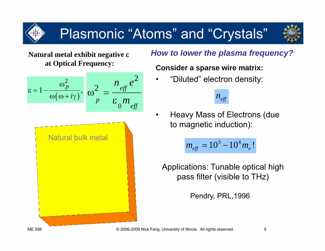
Plasmonic “Atoms” and “Crystals”
Consider a sparse wire matrix:• “Diluted” electron density:
Natural metal exhibit negative at Optical Frequency:
2
How to lower the plasma frequency?
effn
• Diluted electron density:
21 ,p
i
0
22 eff
peff
n e
m
3 4
• Heavy Mass of Electrons (due to magnetic induction):
Natural bulk metal3 410 10 !eff em m
aApplications: Tunable optical high
Pendry, PRL,1996
2r pass filter (visible to THz)
ME 598 © 2006-2009 Nick Fang, University of Illinois. All rights reserved. 9
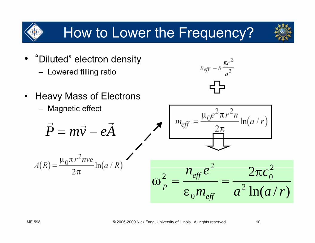
How to Lower the Frequency?
• “Diluted” electron density– Lowered filling ratiog
• Heavy Mass of ElectronsM ti ff t– Magnetic effect
P mv eA
2 22
)/ln(2
2
20
0
22
raac
men
eff
effp
ME 598 © 2006-2009 Nick Fang, University of Illinois. All rights reserved. 10
)(0 eff
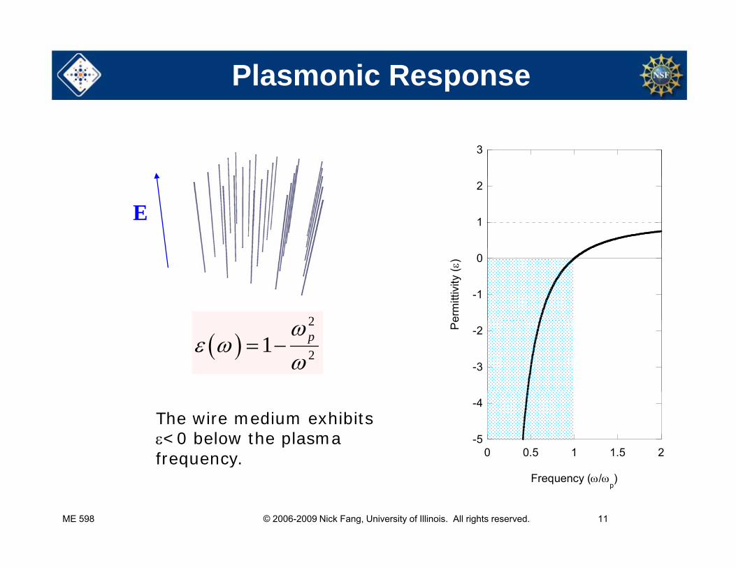
Plasmonic Response
3
E 1
2
2
-1
0
erm
ittiv
ity (
)
2
21 p
-3
-2Pe
-5
-4
0 0.5 1 1.5 2
The wire medium exhibits <0 below the plasma frequency.
ME 598 © 2006-2009 Nick Fang, University of Illinois. All rights reserved. 11
Frequency (/p)
frequency.
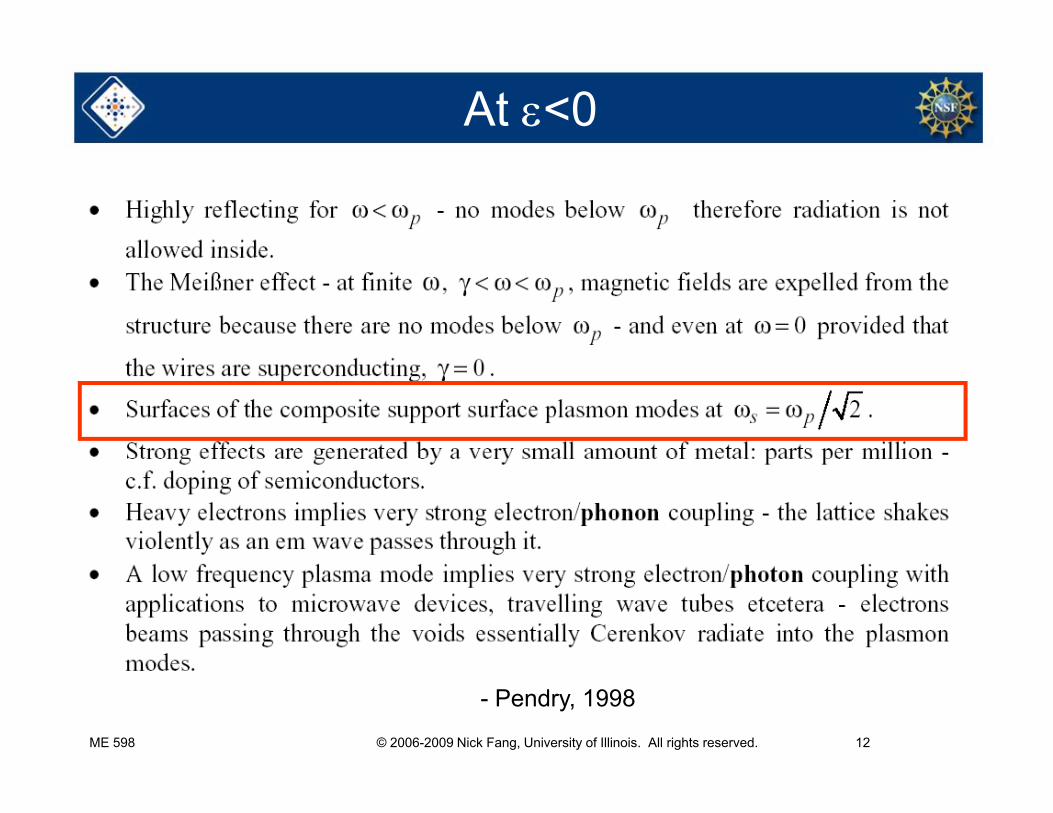
At <0
ME 598 © 2006-2009 Nick Fang, University of Illinois. All rights reserved. 12
- Pendry, 1998
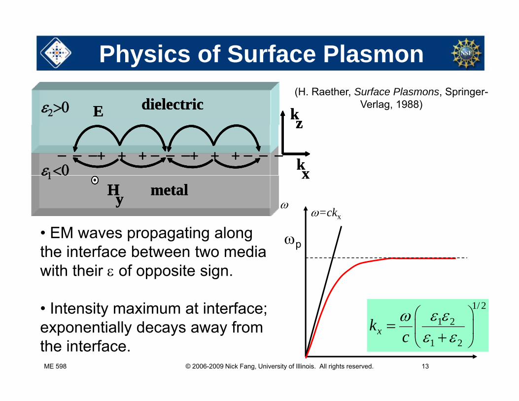
Physics of Surface Plasmon
dielectricE kzdielectricE kzdielectricE kz
(H. Raether, Surface Plasmons, Springer-
Verlag, 1988)
kx + + + + + +
z
+ + + + + +
z
z
kxxmetalHy metalHy metal
Hy
x
=ckx
• EM waves propagating along the interface between two media with their of opposite sign.
p
pp g
• Intensity maximum at interface; exponentially decays away from
1/ 21 2k
ME 598 © 2006-2009 Nick Fang, University of Illinois. All rights reserved. 13
exponentially decays away from the interface. kx1 2
xkc
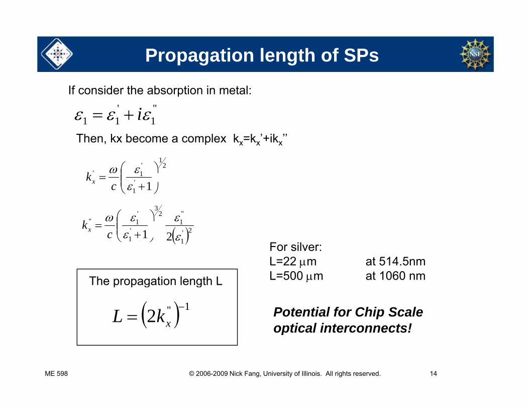
Propagation length of SPs
If consider the absorption in metal:''
1'11 i
Then, kx become a complex kx=kx’+ikx’’
21
'1'
k '1 1
c
kx
2'
''1
23
'
'1''
1
kx 2'
11 21
cx
The propagation length L
For silver: L=22 m at 514.5nmL=500 m at 1060 nmThe propagation length L
1''2 xkL
Potential for Chip Scale optical interconnects!
ME 598 © 2006-2009 Nick Fang, University of Illinois. All rights reserved. 14
p
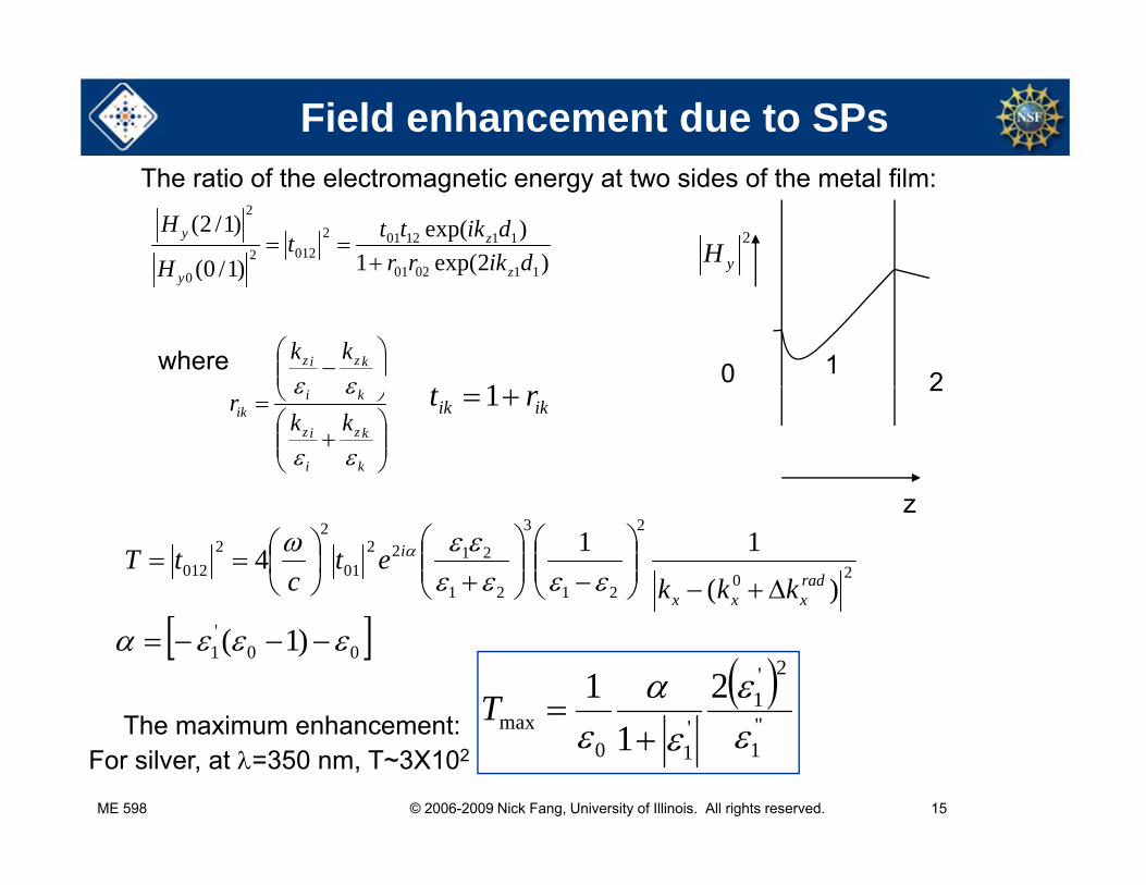
Field enhancement due to SPs
)2exp(1)exp(
)1/0(
)1/2(
110201
11120120122
0
2
dikrrdikttt
H
H
z
zy
2
yH
The ratio of the electromagnetic energy at two sides of the metal film:
)1/0( 1102010H zy
0 12
kziz kk 1
where2
k
kz
i
iz
kiik kk
r
ikik rt 1
z
20
2
21
3
21
212201
22
012)(
114radxxx
i
kkket
ctT
00'1 )1(
''
2'1
'max21
TThe maximum enhancement:
ME 598 © 2006-2009 Nick Fang, University of Illinois. All rights reserved. 15
''1
'10
max 1 The maximum enhancement:For silver, at =350 nm, T~3X10²

High f Magnetism?
e-B a
2r
Magnetism in natural materials f d b 100 GH !
Atome-
fades away above 100 GHz !
(Pendry et al, IEEE MTT, 1999)j Array of Split Ring Resonators
---
+
++
H0C
Bg
The strong capacitive coupling bet een ind cti e c rrent loops
ME 598 © 2006-2009 Nick Fang, University of Illinois. All rights reserved. 16
between inductive current loops leads the magnetic resonance
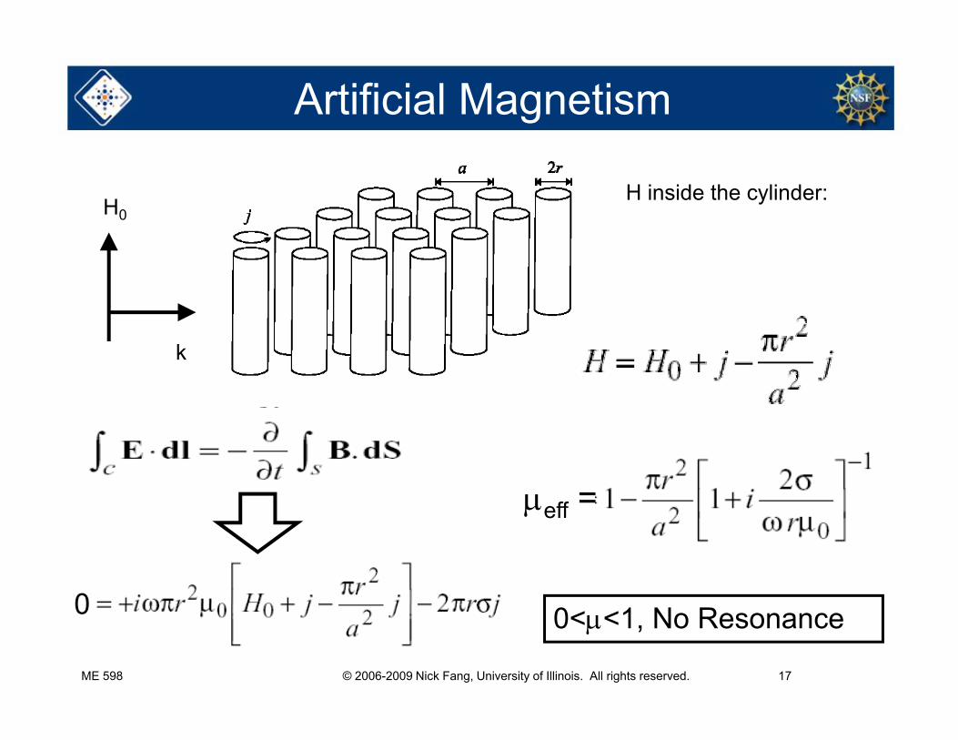
Artificial Magnetism
H0H inside the cylinder:
k
eff =
0
eff
ME 598 © 2006-2009 Nick Fang, University of Illinois. All rights reserved. 17
0 0<<1, No Resonance
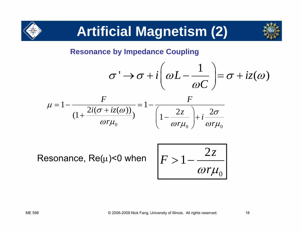
Artificial Magnetism (2)
1' ( )i L i
Resonance by Impedance Coupling
' ( )i L izC
1 1F F
0 0 0
1 12 ( ( )) 2 2(1 ) 1
F Fi iz z ir r r
Resonance, Re()<0 when 21 zF Resonance, Re() 0 when0
1Fr
ME 598 © 2006-2009 Nick Fang, University of Illinois. All rights reserved. 18
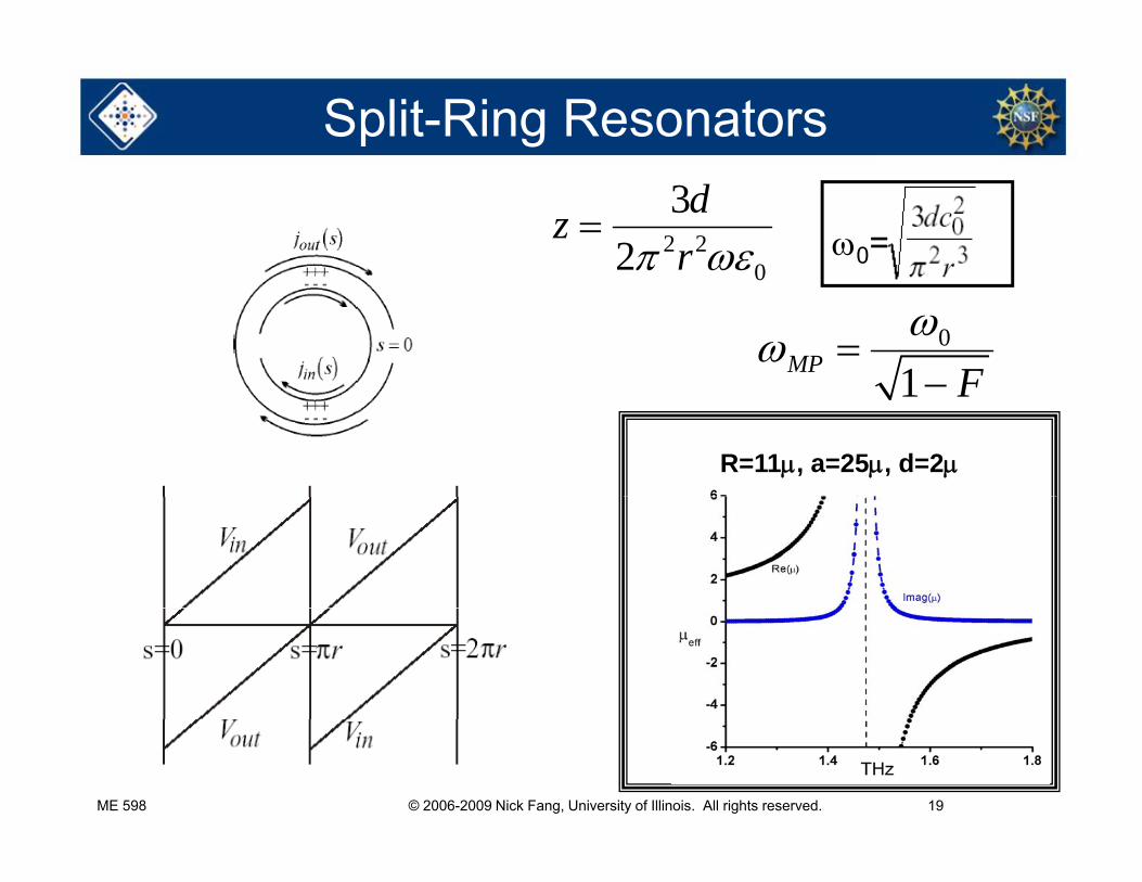
Split-Ring Resonators
2 20
32
dzr
0=0
0
1MP F 1 F
R=11, a=25, d=2
ME 598 © 2006-2009 Nick Fang, University of Illinois. All rights reserved. 19
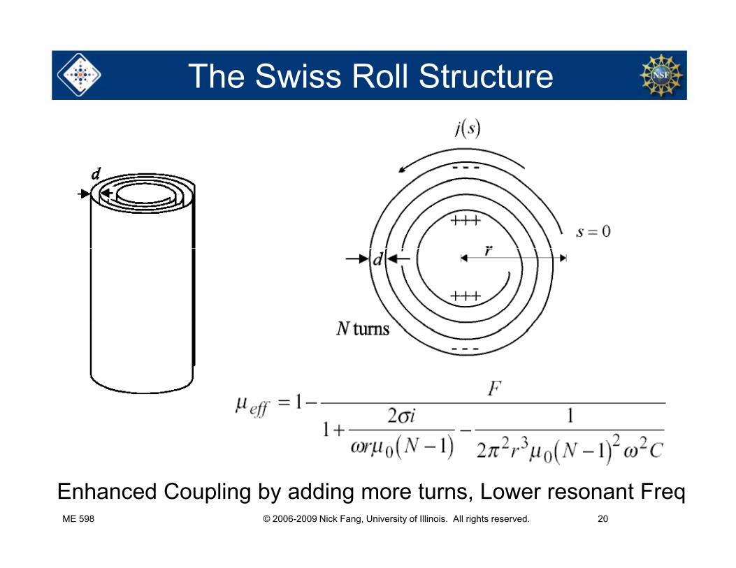
The Swiss Roll Structure
ME 598 © 2006-2009 Nick Fang, University of Illinois. All rights reserved. 20
Enhanced Coupling by adding more turns, Lower resonant Freq
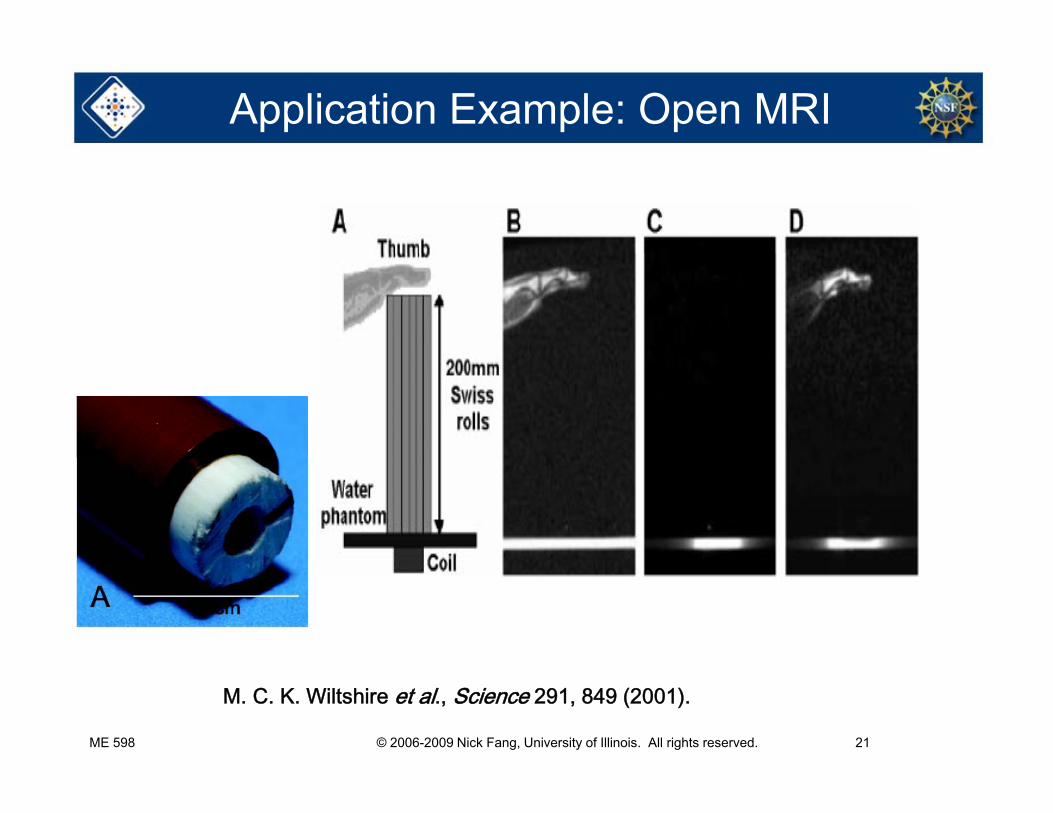
Application Example: Open MRI
ME 598 © 2006-2009 Nick Fang, University of Illinois. All rights reserved. 21
M. C. K. Wiltshire et al., Science 291, 849 (2001).
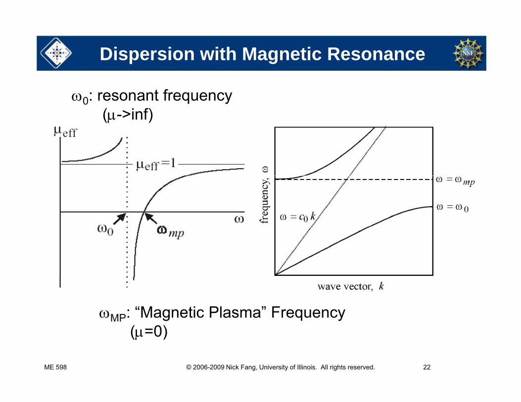
Dispersion with Magnetic Resonance
0: resonant frequency(->inf)
MP: “Magnetic Plasma” Frequency( 0)
ME 598 © 2006-2009 Nick Fang, University of Illinois. All rights reserved. 22
(=0)
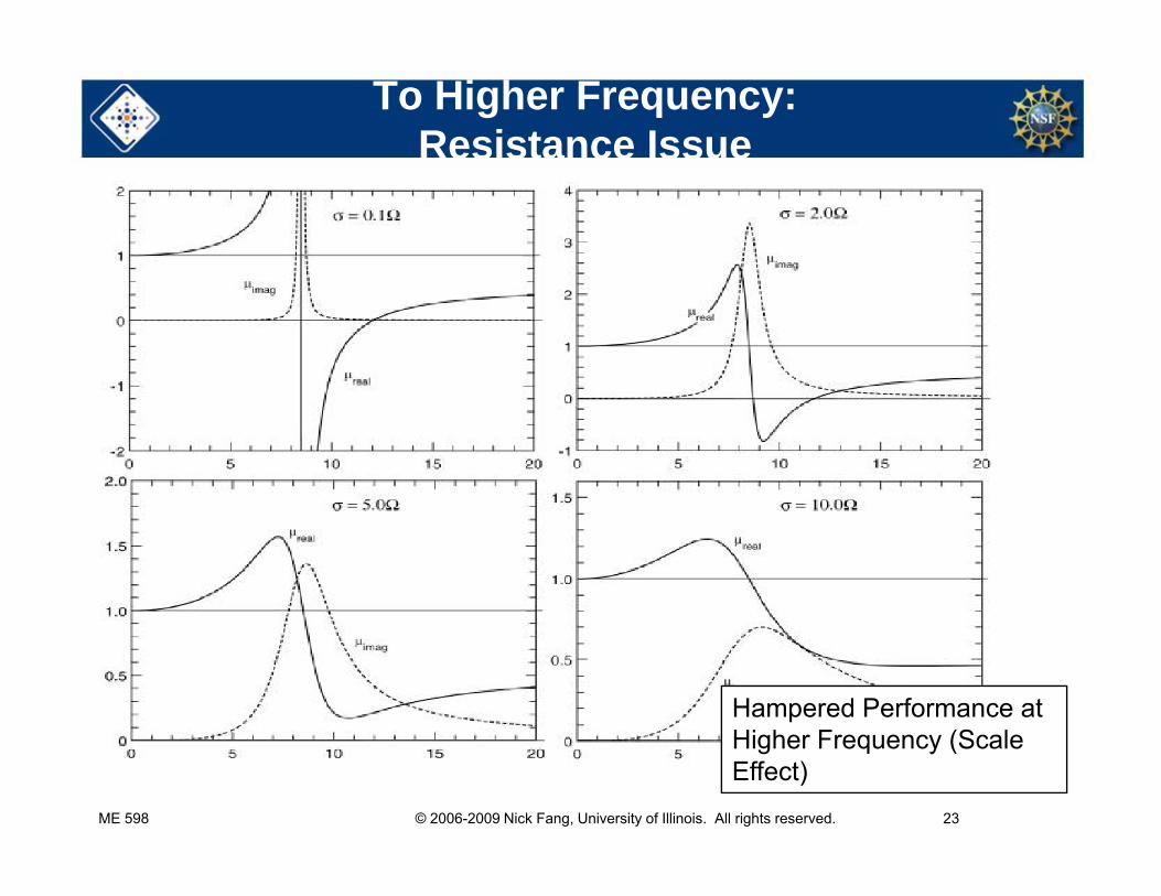
To Higher Frequency: Resistance Issue
Hampered Performance at Hi h F (S l
ME 598 © 2006-2009 Nick Fang, University of Illinois. All rights reserved. 23
Higher Frequency (Scale Effect)
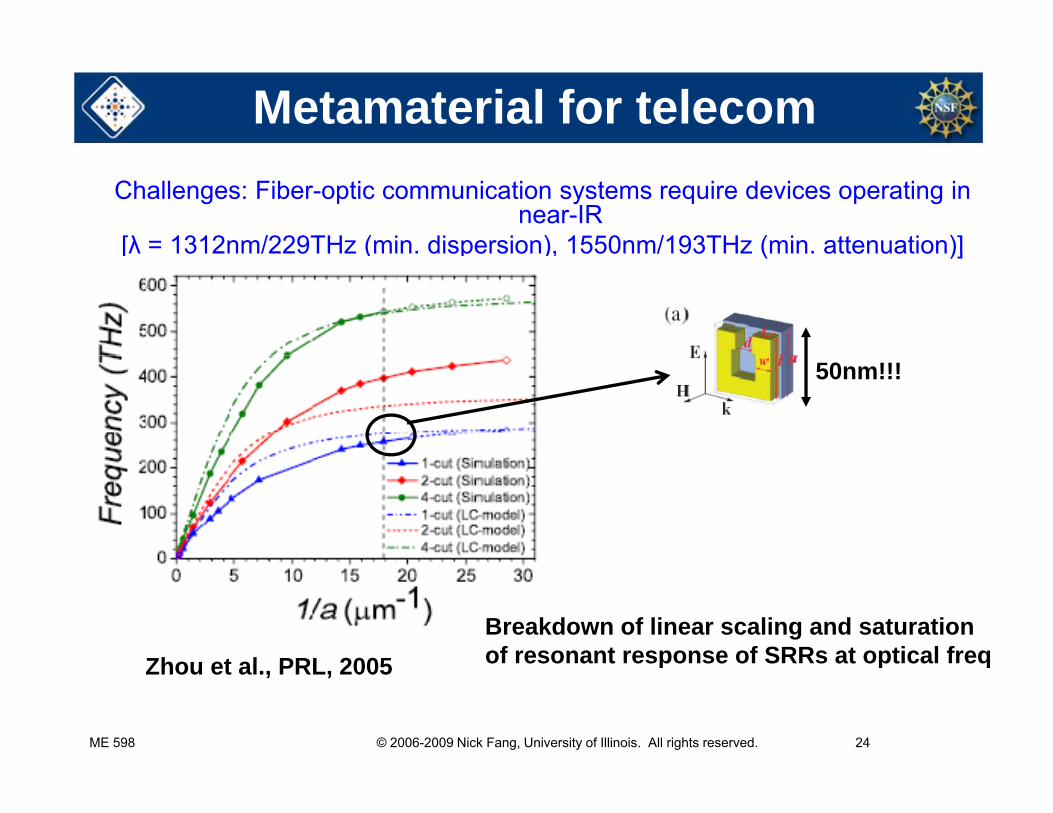
Metamaterial for telecomChallenges: Fiber-optic communication systems require devices operating in
near-IR [λ = 1312nm/229THz (min. dispersion), 1550nm/193THz (min. attenuation)][λ 1312nm/229THz (min. dispersion), 1550nm/193THz (min. attenuation)]
50nm!!!
Breakdown of linear scaling and saturation of resonant response of SRRs at optical freqZhou et al PRL 2005
ME 598 © 2006-2009 Nick Fang, University of Illinois. All rights reserved. 24
of resonant response of SRRs at optical freqZhou et al., PRL, 2005
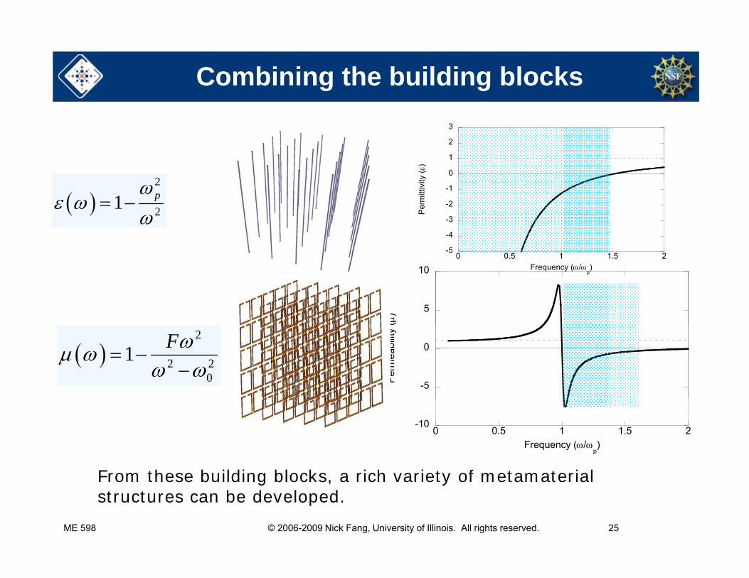
Combining the building blocks
20
1
2
3
ty (
)
2
21 p
-5
-4
-3
-2
-1
Per
mitt
ivit
5
10
()
50 0.5 1 1.5 2
Frequency (/p)
2
2 20
1 F
-5
0
Per
mea
bilit
y
-100 0.5 1 1.5 2
Frequency (/p)
F th b ildi bl k i h i t f t t i l
ME 598 © 2006-2009 Nick Fang, University of Illinois. All rights reserved. 25
From these building blocks, a rich variety of metamaterial structures can be developed.
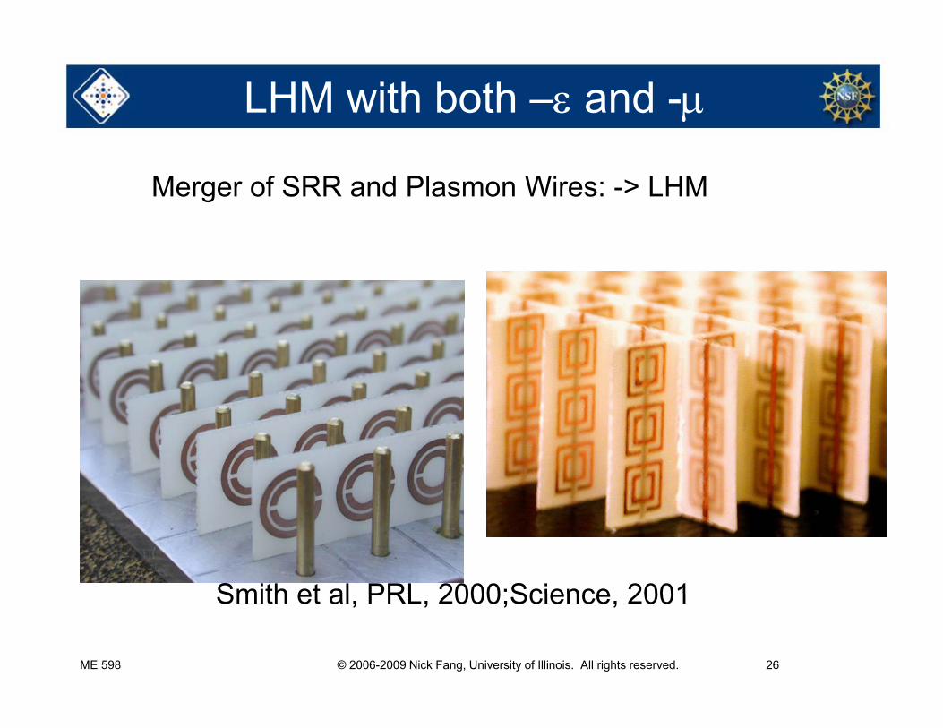
LHM with both – and -
Merger of SRR and Plasmon Wires: -> LHM
Smith et al PRL 2000;Science 2001
ME 598 © 2006-2009 Nick Fang, University of Illinois. All rights reserved. 26
Smith et al, PRL, 2000;Science, 2001
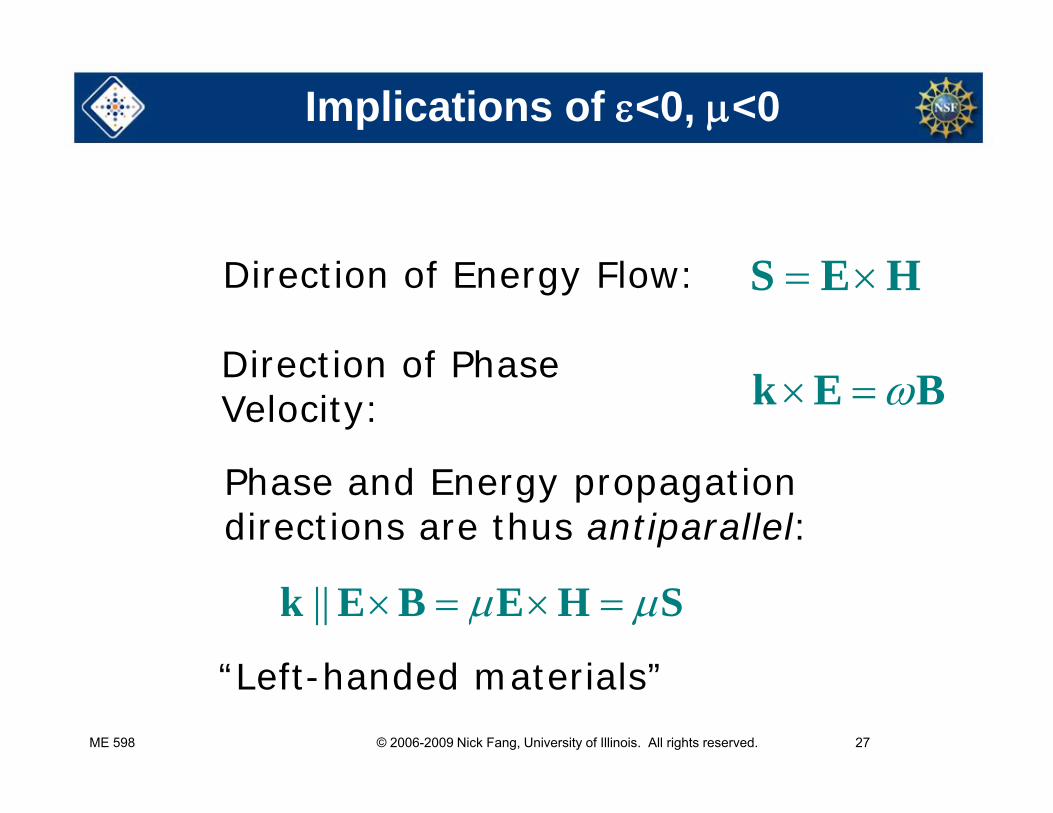
Implications of <0, <0
Direction of Energy Flow: S E H
Di ti f Ph k E BDirection of Phase Velocity:
Phase and Energy propagation directions are thus antiparallel:
|| k E B E H S
“L f h d d i l ”
ME 598 © 2006-2009 Nick Fang, University of Illinois. All rights reserved. 27
“Left-handed materials”
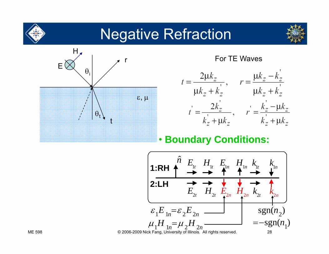
Negative Refractionr
i
For TE WavesH
E
,
• Boundary Conditions:
tt
y
1tE 1tH 1nE 1nH 1tk 1nkn̂1:RH
2tE 2tH 2nE 2nH 2tk 2nk2:LH
E E ( )
ME 598 © 2006-2009 Nick Fang, University of Illinois. All rights reserved. 28
1 1 2 2 n nE E
1 1 2 2 n nH H2
1
sgn( )sgn( )
nn
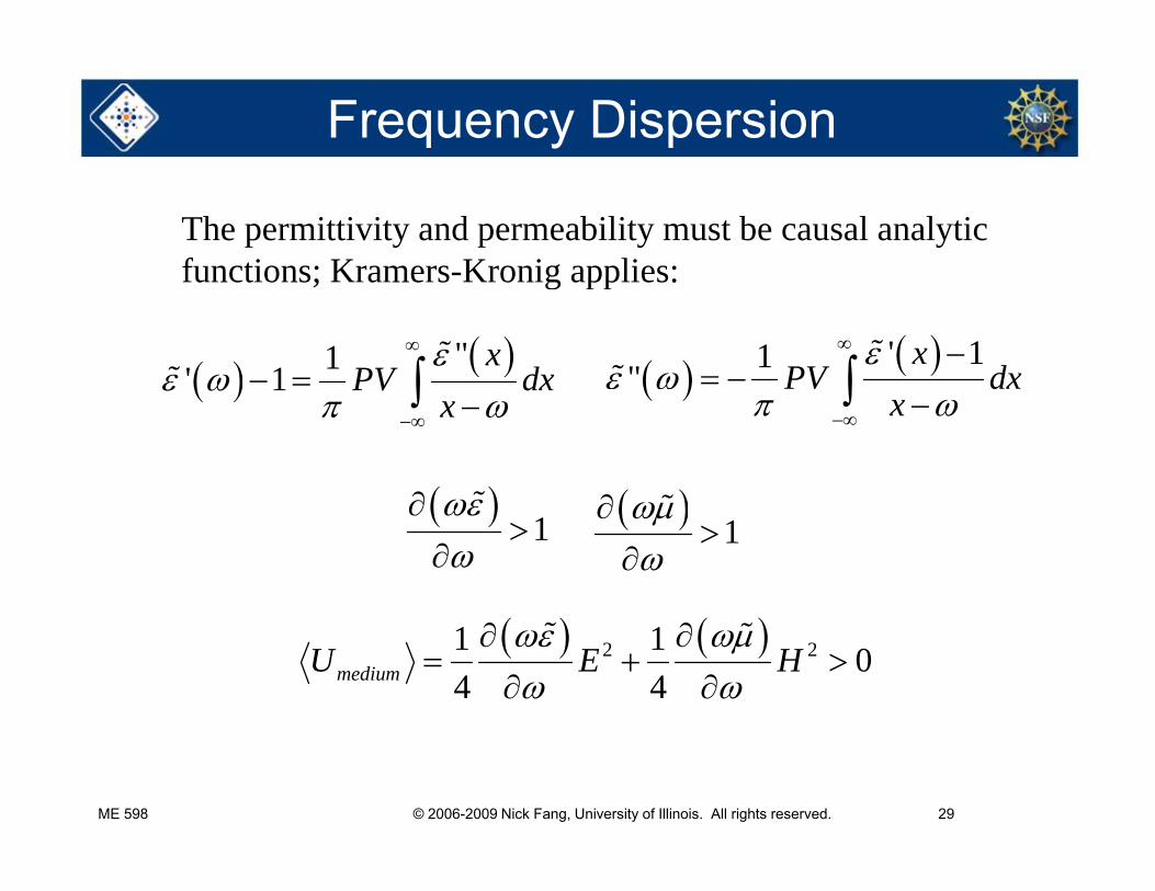
Frequency Dispersion
The permittivity and permeability must be causal analytic functions; Kramers-Kronig applies:
"1' 1x
PV dx
' 11"x
PV dx
functions; Kramers Kronig applies:
1 PV dxx
x
1
1
2 21 1 04 4mediumU E H
ME 598 © 2006-2009 Nick Fang, University of Illinois. All rights reserved. 29
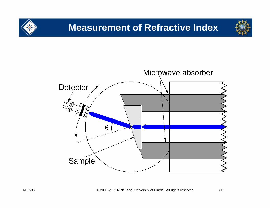
Measurement of Refractive Index
ME 598 © 2006-2009 Nick Fang, University of Illinois. All rights reserved. 30
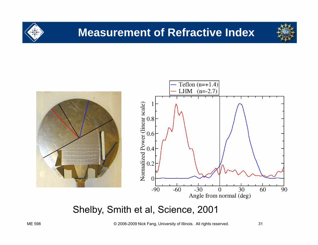
Measurement of Refractive Index
ME 598 © 2006-2009 Nick Fang, University of Illinois. All rights reserved. 31
Shelby, Smith et al, Science, 2001
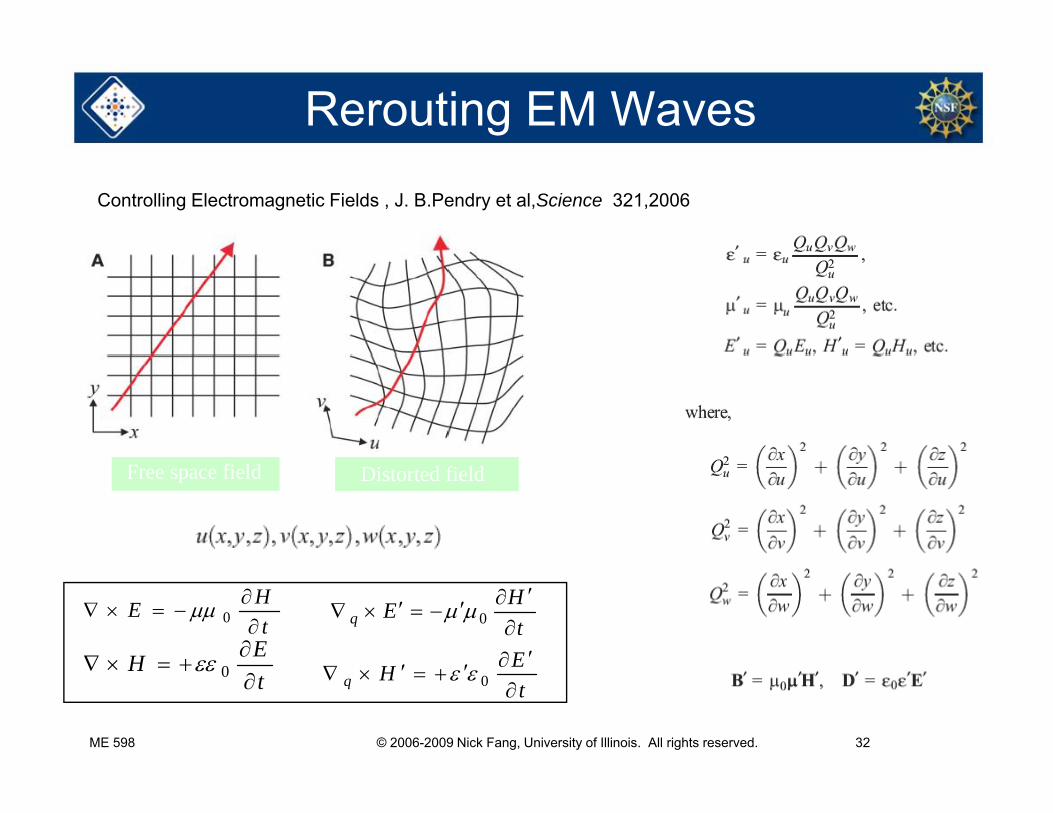
Rerouting EM Waves
Controlling Electromagnetic Fields , J. B.Pendry et al,Science 321,2006
Distorted fieldFree space field
tHE
0
EH
tHEq 0
E
ME 598 © 2006-2009 Nick Fang, University of Illinois. All rights reserved. 32
tH
0
tEHq
0
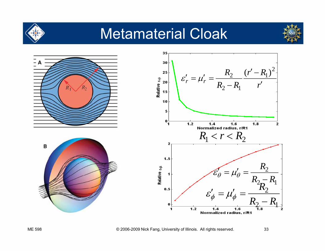
Metamaterial Cloak
RrR
212 )(
rRRrr
12
21 RrR 21
2R
12 RR
12
2
RRR
ME 598 © 2006-2009 Nick Fang, University of Illinois. All rights reserved. 33
12
Invisibility cloak
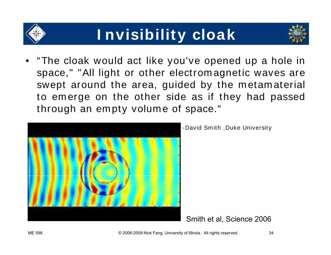
• “The cloak would act like you've opened up a hole inspace," "All light or other electromagnetic waves areswept around the area, guided by the metamaterialto emerge on the other side as if they had passedthrough an empty volume of space.“through an empty volume of space.
-David Smith ,Duke University
ME 598 © 2006-2009 Nick Fang, University of Illinois. All rights reserved. 34
Smith et al, Science 2006
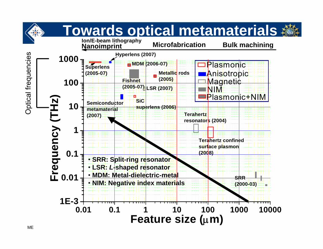
Towards optical metamaterialsNanoimprintIon/E-beam lithography Microfabrication Bulk machining
1000Nanoimprint Microfabrication
AnisotropicMetallic rods(2005)
MDM (2006-07)
Hyperlens (2007)
Superlens(2005-07)
Plasmonic
Bulk machining
uenc
ies
10
100Plasmonic+NIMNIMMagnetic
p
SiC superlens (2006)
(2005)
LSR (2007)
Semiconductormetamaterial
Fishnet(2005-07)
Hz)
ptic
al fr
eq
1
10 p ( )metamaterial (2007) Terahertz
resonators (2004)
Terahertz confinedncy
(THO
0.1Terahertz confined surface plasmon(2008)
requ
en
• SRR: Split-ring resonator• LSR: L-shaped resonator
1E-3
0.01 SRR(2000-03)
Fr • MDM: Metal-dielectric-metal• NIM: Negative index materials
ME 598 © 2006-2009 Nick Fang, University of Illinois. All rights reserved. 35
0.01 0.1 1 10 100 1000 100001E 3
Feature size (m)
Other interesting Topics
• The Maxwell Stress Tensor: how the artificial atoms interactatoms interact
• Moving media: Negative Doppler effectMoving media: Negative Doppler effect
• High f magnetism: how to demonstrate magnetic• High f magnetism: how to demonstrate magnetic effect?– The Meissner effect and phase transitionp– Magnonic lattice?
ME 598 © 2006-2009 Nick Fang, University of Illinois. All rights reserved. 36
References• Extremely-Low-Frequency Plasmons in Metallic Mesostructures,J.B. Pendry,
A.T. Holden, W.J. Stewart and I. Youngs, Phys. Rev. Lett., 25, 4773 (1996).
• Low Frequency Plasmons in Thin Wire Structures, J.B. Pendry, AJ Holden, DJ Robbins, and WJ Stewart, J. Phys. Cond. Matt., 10, 4785 (1998).
• Magnetism from Conductors, and Enhanced Non-Linear Phenomena, JB Pendry, AJ Holden, DJ Robbins, and WJ Stewart, IEEE transactions on microwave theory and techniques 47,2075 (1999).
• Metamaterials and Negative Refractive Index, DR Smith, JB Pendry, MCK Wiltshire, Science 305 788-92 (2004)
• Metamaterials and the Control of Electromagnetic Fields, JB Pendry, Proceedings of the Ninth Rochester Conference on Coherence and Quantum Optics (2007)
ME 598 © 2006-2009 Nick Fang, University of Illinois. All rights reserved. 37
Optics (2007)
Related Documents


