eng i Declaration of Conformity ‑ For Recreational Craft Propulsion Engines with the Requirements of Directive 94/25/EC as amended by Directive 2003/44/EC Name of engine manufacturer: Mercury Marine Address: W6250 W. Pioneer Road, P.O. Box 1939 Town: Fond du Lac, WI Post Code: 54936‑1939 Country: USA Name of Authorized Representative: Brunswick Marine in EMEA Inc. Address: Parc Industriel de Petit‑Rechain Town: Verviers Post Code: B‑2800 Country: Belgium Name of Notified Body for exhaust emission assessment: Det Norske Veritas AS Address: Veritasveien 1 Town: Hovik Post Code: 1322 Country: Norway ID Number: 0575 Name of Notified Body for noise emission assessment: Det Norske Veritas AS Address: Veritasveien 1 Town: Hovik Post Code: 1322 Country: Norway ID Number: 0575 Conformity assessment module used for exhaust emissions: ☐ B +C ☐ B +D ☐ B +E ☐ B +F ☐ G ☒ H Conformity assessment module used for noise emissions: ☐ A ☐ Aa ☐ G ☒ H Other Community Directives applied: Safety of Machinery Directive 2006/42/EC; Electromagnetic Compatibility Directive 2004/108/EC Description of Engines and Essential Requirements Engine Type Fuel Type Combustion Cycle ☒ Outboard engine ☒ Petrol ☒ 4 stroke © 2013 Mercury Marine 225/250/250-300 Pro/300 Verado FourStroke 90-8M0078341 113

Welcome message from author
This document is posted to help you gain knowledge. Please leave a comment to let me know what you think about it! Share it to your friends and learn new things together.
Transcript
eng i
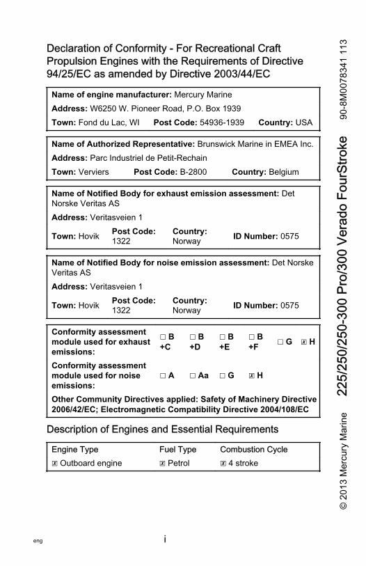
Declaration of Conformity ‑ For Recreational CraftPropulsion Engines with the Requirements of Directive94/25/EC as amended by Directive 2003/44/EC
Name of engine manufacturer: Mercury MarineAddress: W6250 W. Pioneer Road, P.O. Box 1939Town: Fond du Lac, WI Post Code: 54936‑1939 Country: USA
Name of Authorized Representative: Brunswick Marine in EMEA Inc.Address: Parc Industriel de Petit‑RechainTown: Verviers Post Code: B‑2800 Country: Belgium
Name of Notified Body for exhaust emission assessment: DetNorske Veritas ASAddress: Veritasveien 1
Town: Hovik Post Code:1322
Country:Norway ID Number: 0575
Name of Notified Body for noise emission assessment: Det NorskeVeritas ASAddress: Veritasveien 1
Town: Hovik Post Code:1322
Country:Norway ID Number: 0575
Conformity assessmentmodule used for exhaustemissions:
☐ B+C
☐ B+D
☐ B+E
☐ B+F ☐ G ☒ H
Conformity assessmentmodule used for noiseemissions:
☐ A ☐ Aa ☐ G ☒ H
Other Community Directives applied: Safety of Machinery Directive2006/42/EC; Electromagnetic Compatibility Directive 2004/108/EC
Description of Engines and Essential Requirements
Engine Type Fuel Type Combustion Cycle☒ Outboard engine ☒ Petrol ☒ 4 stroke
© 2
013
Mer
cury
Mar
ine
225/
250/
250-
300
Pro/
300
Vera
do F
ourS
troke
90-8
M00
7834
1 11
3
ii eng
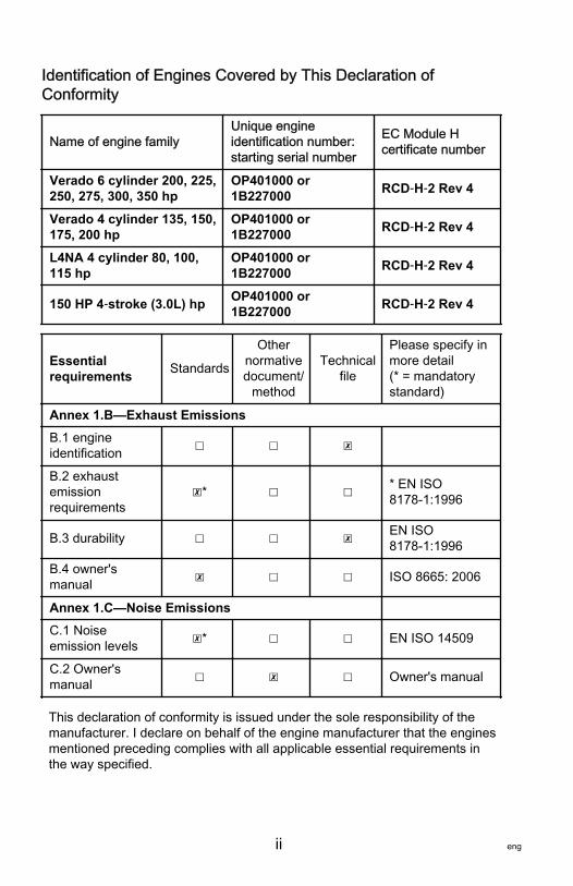
Identification of Engines Covered by This Declaration ofConformity
Name of engine familyUnique engineidentification number:starting serial number
EC Module Hcertificate number
Verado 6 cylinder 200, 225,250, 275, 300, 350 hp
OP401000 or1B227000 RCD‑H‑2 Rev 4
Verado 4 cylinder 135, 150,175, 200 hp
OP401000 or1B227000 RCD‑H‑2 Rev 4
L4NA 4 cylinder 80, 100,115 hp
OP401000 or1B227000 RCD‑H‑2 Rev 4
150 HP 4‑stroke (3.0L) hp OP401000 or1B227000 RCD‑H‑2 Rev 4
Essentialrequirements Standards
Othernormativedocument/
method
Technicalfile
Please specify inmore detail(* = mandatorystandard)
Annex 1.B—Exhaust EmissionsB.1 engineidentification ☐ ☐ ☒
B.2 exhaustemissionrequirements
☒* ☐ ☐ * EN ISO8178‑1:1996
B.3 durability ☐ ☐ ☒ EN ISO8178‑1:1996
B.4 owner'smanual ☒ ☐ ☐ ISO 8665: 2006
Annex 1.C—Noise EmissionsC.1 Noiseemission levels ☒* ☐ ☐ EN ISO 14509
C.2 Owner'smanual ☐ ☒ ☐ Owner's manual
This declaration of conformity is issued under the sole responsibility of themanufacturer. I declare on behalf of the engine manufacturer that the enginesmentioned preceding complies with all applicable essential requirements inthe way specified.
eng iii
Name / function:Mark D. Schwabero, President,Mercury Outboard
Date and place of issue:September 04, 2012Fond du Lac, Wisconsin, USA
WelcomeYou have selected one of the finest outboards available. Itincorporates numerous design features to ensure operating easeand durability.With proper care and maintenance, you will thoroughly enjoyusing this product for many boating seasons. To ensuremaximum performance and carefree use, we ask that youthoroughly read this manual.The Operation, Maintenance and Warranty Manual containsspecific instructions for using and maintaining your product. Wesuggest that this manual remain with the product for readyreference whenever you are on the water.Thank you for purchasing one of our products. We sincerelyhope your boating will be pleasant!Mercury Marine
EPA Emissions RegulationsOutboards sold by Mercury Marine in the United States arecertified to the United States Environmental Protection Agencyas conforming to the requirements of the regulations for thecontrol of air pollution from new outboard motors. Thiscertification is contingent on certain adjustments being set tofactory standards. For this reason, the factory procedure forservicing the product must be strictly followed and, whereverpracticable, returned to the original intent of the design.Maintenance, replacement, or repair of the emission controldevices and systems may be performed by any marine enginerepair establishment or individual.
iv eng
Engines are labeled with an Emission Control Information decalas permanent evidence of EPA certification.
! WARNINGThe engine exhaust from this product contains chemicalsknown to the state of California to cause cancer, birth defectsor other reproductive harm.
Warranty MessageThe product you have purchased comes with a limited warrantyfrom Mercury Marine. The terms of the warranty are set forth inthe Warranty Information section of this manual. The warrantystatement contains a description of what is covered, what is notcovered, the duration of coverage, how to best obtain warrantycoverage, important disclaimers and limitations of damages, andother related information. Please review this importantinformation.The description and specifications contained herein were ineffect at the time this manual was approved for printing. MercuryMarine, whose policy is one of continued improvement, reservesthe right to discontinue models at any time, to changespecifications, designs, methods, or procedures without noticeand without incurring obligation.Mercury Marine, Fond du Lac, Wisconsin U.S.A.Printed in the U.S.A.© 2013, Mercury MarineAlpha, Axius, Bravo One, Bravo Two, Bravo Three, Circle M withWaves Logo, K‑planes, Mariner, MerCathode, MerCruiser,Mercury, Mercury with Waves Logo, Mercury Marine, MercuryPrecision Parts, Mercury Propellers, Mercury Racing,MotorGuide, OptiMax, Quicksilver, SeaCore, Skyhook,SmartCraft, Sport‑Jet, Verado, VesselView, Zero Effort, Zeus,and #1 On the Water are registered trademarks of BrunswickCorporation. Mercury Product Protection is a registered servicemark of Brunswick Corporation.
eng v
Mercury Premier ServiceMercury evaluates the service performance of its dealers andassigns its highest rating of "Mercury Premier" to thosedemonstrating an exceptional commitment to service.Earning a Mercury Premier Service rating means a dealer:• Achieves a high 12‑month service Customer Satisfaction
Index (CSI) score for warranty service.• Possesses all of the necessary service tools, test
equipment, manuals, and parts books.• Employs at least one certified or master technician.• Provides timely service for all Mercury Marine customers.• Offers extended service hours and mobile service, when
appropriate.• Uses, displays, and stocks an adequate inventory of
genuine Mercury Precision Parts.• Offers a clean, neat shop with well‑organized tools and
service literature.

vi eng
eng vii
WARRANTY INFORMATION
Warranty Registration United States and Canada....................... 1Transfer of Warranty United States and Canada.........................1Transfer of Mercury Product Protection (Extended ServiceCoverage) Plan United States and Canada.................................2FourStroke Outboard Limited Warranty United States andCanada........................................................................................ 3FourStroke Outboard Limited Warranty Europe andConfederation of Independent States.......................................... 6FourStroke Outboard Limited Warranty Middle‑East and Africa................................................................................................... 103 Year Limited Warranty Against Corrosion.............................. 14Warranty Coverage and Exclusions.......................................... 17U.S. EPA Emissions Limited Warranty...................................... 19Emission Control System Components..................................... 19California Emissions Limited Warranty...................................... 20California Air Resources Board Explanation of Your CaliforniaEmission Control Warranty Statement.......................................24Emission Certification Star Label............................................... 25Warranty Policy—Australia and New Zealand........................... 26
viii eng
General Information
Boater's Responsibilities............................................................ 33Before Operating Your Outboard............................................... 33Boat Horsepower Capacity........................................................ 34High‑Speed and High‑Performance Boat Operation................. 34Outboard Remote Control Models ............................................ 34Lanyard Stop Switch.................................................................. 35Protecting People in the Water.................................................. 38Exhaust Emissions.................................................................... 39Passenger Safety Message ‑ Pontoon Boats and Deck Boats................................................................................................... 41Wave and Wake Jumping.......................................................... 43Impact with Underwater Hazards...............................................44Selecting Accessories for Your Outboard.................................. 45Safe Boating Recommendations............................................... 45Recording Serial Number.......................................................... 49Specifications.............................................................................49Component Identification........................................................... 51Propeller Selection.....................................................................51
Transporting
Trailering Boat/Outboard .......................................................... 55
Fuel and Oil
Fuel Recommendations............................................................. 57Low Permeation Fuel Hose Requirement ................................. 59EPA Pressurized Portable Fuel Tank Requirements................. 59Fuel Demand Valve (FDV) Requirement................................... 60Mercury Marine's Pressurized Portable Fuel Tank.................... 60Filling Fuel Tank........................................................................ 62Engine Oil Recommendations................................................... 62Checking and Adding Engine Oil............................................... 63
eng ix
Features and Controls
Panel Mount Control Features and Operation........................... 66Single Handle Console Control Features and Operation...........69Slim Binnacle Control Features and Operation......................... 74Dual Handle Console Control Features and Operation............. 78Dual Handle Console Control with CAN Trackpad Features andOperation................................................................................... 83Shadow Mode Control Features and Operation........................ 88Shadow Mode Control with CAN Trackpad Features andOperation................................................................................... 96Warning System...................................................................... 105Power Trim and Tilt..................................................................108
Operation
Important Daily Inspection Before Each Use .......................... 113Prestarting Check List..............................................................113Operating in Freezing Temperatures....................................... 114Operating in Saltwater or Polluted Water................................ 114Operating at High Elevations................................................... 114Effects of Elevation and Weather on Performance.................. 115Setting Trim Angle While Running Engine at Idle Speed........ 116Engine Break‑in Procedure......................................................116Starting the Engine.................................................................. 116Gear Shifting............................................................................ 119Stopping the Engine................................................................ 121
x eng
Maintenance
Outboard Care......................................................................... 122EPA Emissions Regulations.................................................... 122Inspection and Maintenance Schedule.................................... 123Flushing the Cooling System................................................... 126Cowl Removal and Installation................................................ 127Cleaning Care for Top and Bottom Cowls............................... 129Cleaning Care for the Powerhead (Saltwater Use)..................129Battery Inspection ................................................................... 130Verado Engine Battery Specifications..................................... 130Air Filter................................................................................... 132Fuel System............................................................................. 134Corrosion Control Anodes....................................................... 139Propeller Replacement ‑ 25.4 mm (1.0 in.) Diameter PropellerShaft........................................................................................ 139Propeller Replacement ‑ 31.75 mm (1‑1/4 in.) Diameter PropellerShaft........................................................................................ 142Spark Plug Inspection and Replacement.................................143Fuses....................................................................................... 146DTS Wiring System................................................................. 148Accessory Drive Belt Inspection.............................................. 148Checking Power Trim Fluid......................................................148Checking Power Steering Fluid............................................... 150Changing Engine Oil ............................................................... 150Gearcase Lubrication...............................................................154
Storage
Storage Preparation.................................................................159Protecting External Outboard Components............................. 160Protecting Internal Engine Components.................................. 160Gearcase................................................................................. 160Positioning Outboard for Storage............................................ 161Battery Storage........................................................................ 161
eng xi
Troubleshooting
Starter Motor Will Not Crank the Engine..................................162Engine Will Not Start................................................................162Engine Starts But Will Not Shift Into Gear............................... 162Engine Runs Erratically........................................................... 163Performance Loss....................................................................163Battery Will Not Hold Charge................................................... 163
Owner Service Assistance
Local Repair Service................................................................165Service Away from Home........................................................ 165Parts and Accessories Inquiries.............................................. 165Service Assistance.................................................................. 165Ordering Literature...................................................................168
Installation
Installing Outboard...................................................................170Propeller Selection...................................................................173
Maintenance Log
Maintenance Log..................................................................... 174

xii eng
WARRANTY INFORMATION
eng 1
Warranty Registration United States and CanadaTo be eligible for warranty coverage, the product must beregistered with Mercury Marine.At the time of sale, the selling dealer should complete thewarranty registration and immediately submit it to MercuryMarine via MercNET, e‑mail, or mail. Upon receipt of thiswarranty registration, Mercury Marine will record the registration.A copy of the warranty registration should be provided to you byyour selling dealer.NOTE: Registration lists must be maintained by Mercury Marineand any dealer of Mercury Marine products sold in the UnitedStates, should a safety recall notification under the FederalSafety Act be required.You may change your registered address at any time, includingat time of warranty claim, by calling Mercury Marine or sending aletter or fax with your name, old address, new address, andengine serial number to Mercury Marine’s warranty registrationdepartment. Your dealer can also process this change ofinformation.Mercury MarineAttn: Warranty Registration DepartmentW6250 W. Pioneer RoadP.O. Box 1939Fond du Lac, WI 54936-1939920-929-5054Fax +1 920 907 6663
OUTSIDE UNITED STATES AND CANADAFor products purchased outside the United States and Canada,contact the distributor in your country, or the Marine PowerService Center closest to you.
Transfer of Warranty United States and CanadaThe limited warranty is transferable to a subsequent purchaser,but only for the remainder of the unused portion of the limitedwarranty. This will not apply to products used for commercialapplications.
WARRANTY INFORMATION
2 eng
To transfer the warranty to the subsequent owner, send or fax acopy of the bill of sale or purchase agreement, new owner’sname, address, and engine serial number to Mercury Marine’swarranty registration department. In the United States andCanada, mail to:Mercury MarineAttn: Warranty Registration DepartmentW6250 W. Pioneer RoadP.O. Box 1939Fond du Lac, WI 54936-1939920-929-5054Fax +1 920 907 6663Upon processing the transfer of warranty, Mercury Marine willrecord the new owner's information.There is no charge for this service.
OUTSIDE THE UNITED STATES AND CANADAFor products purchased outside the United States and Canada,contact the distributor in your country, or the Marine PowerService Center closest to you.
Transfer of Mercury Product Protection (ExtendedService Coverage) Plan United States and CanadaThe remaining coverage period of the Product Protection Plan istransferable to the subsequent purchaser of the engine withinthirty (30) days from the date of sale. Contracts not transferredwithin thirty (30) days of the subsequent purchase will no longerbe valid and the product will no longer be eligible for coverageunder the terms of the contract.To transfer the plan to the subsequent owner, contact MercuryProduct Protection or an authorized dealer to receive a Requestfor Transfer form. Submit to Mercury Product Protection areceipt/bill of sale, a completed Request of Transfer form, and acheck payable to Mercury Marine in the amount of $50.00 (perengine) to cover the transfer fee.Plan coverage is not transferable from one product to anotherproduct or for noneligible applications.The certified preowned engine plans are not transferable.
WARRANTY INFORMATION
eng 3
For help or assistance, contact Mercury Product ProtectionDepartment at 1‑888‑427‑5373 from 7:30 a.m. to 4:30 p.m. CST,Monday–Friday or e‑mail [email protected].
FourStroke Outboard Limited Warranty UnitedStates and CanadaOutside the United States and Canada ‑ Check with your localdistributor.WHAT IS COVERED: Mercury Marine warrants its new productsto be free of defects in material and workmanship during theperiod described below.DURATION OF COVERAGE: This Limited Warranty providescoverage for three (3) years from the date the product is first soldto a recreational use retail purchaser, or the date on which theproduct is first put into service, whichever occurs first.Commercial users of these products receive warranty coverageof one (1) year from the date of first retail sale, or one (1) yearfrom the date on which the product was first put into service,whichever occurs first. Commercial use is defined as any work oremployment related use of the product, or any use of the productwhich generates income, for any part of the warranty period,even if the product is only occasionally used for such purposes.The repair or replacement of parts, or the performance of serviceunder this warranty, does not extend the life of this warrantybeyond its original expiration date. Unexpired warranty coveragecan be transferred from one recreational use customer to asubsequent recreational use customer upon proper reregistrationof the product. Unexpired warranty coverage cannot betransferred either to or from a commercial use customer.Warranty coverage may be terminated for used repossessedproduct; or product purchased at auction, from a salvage yard, orfrom an insurance company.
WARRANTY INFORMATION
4 eng
CONDITIONS THAT MUST BE MET IN ORDER TO OBTAINWARRANTY COVERAGE: Warranty coverage is available onlyto retail customers that purchase from a Dealer authorized byMercury Marine to distribute the product in the country in whichthe sale occurred, and then only after the Mercury Marinespecified predelivery inspection process is completed anddocumented. Warranty coverage becomes available upon properregistration of the product by the authorized dealer. Inaccuratewarranty registration information regarding recreational use, orsubsequent change of use from recreational to commercial(unless properly reregistered) may void the warranty at the solediscretion of Mercury Marine. Routine maintenance outlined inthe Operation and Maintenance Manual must be timelyperformed in order to maintain warranty coverage. MercuryMarine reserves the right to make warranty coverage contingentupon proof of proper maintenance.WHAT MERCURY WILL DO: Mercury's sole and exclusiveobligation under this warranty is limited to, at our option,repairing a defective part, replacing such part or parts with newor Mercury Marine certified remanufactured parts, or refundingthe purchase price of the Mercury product. Mercury reserves theright to improve or modify products from time to time withoutassuming an obligation to modify products previouslymanufactured.
WARRANTY INFORMATION
eng 5
HOW TO OBTAIN WARRANTY COVERAGE: The customermust provide Mercury with a reasonable opportunity to repair,and reasonable access to the product for warranty service.Warranty claims shall be made by delivering the product forinspection to a Mercury dealer authorized to service the product.If purchaser cannot deliver the product to such a dealer, writtennotice must be given to Mercury. We will then arrange for theinspection and any covered repair. Purchaser, in that case, shallpay for all related transportation charges and/or travel time. If theservice provided is not covered by this warranty, purchaser shallpay for all related labor and material, and any other expensesassociated with that service. Purchaser shall not, unlessrequested by Mercury, ship the product or parts of the productdirectly to Mercury. Proof of registered ownership must bepresented to the dealer at the time warranty service is requestedin order to obtain coverage.WHAT IS NOT COVERED: This limited warranty does not coverroutine maintenance items, tune‑ups, adjustments, normal wearand tear, damage caused by abuse, abnormal use, use of apropeller or gear ratio that does not allow the engine to run in itsrecommended wide‑open throttle RPM range (see the Operationand Maintenance Manual), operation of the product in a mannerinconsistent with the recommended operation/duty cycle sectionof the Operation and Maintenance Manual, neglect, accident,submersion, improper installation (proper installationspecifications and techniques are set forth in the installationinstructions for the product), improper service, use of anaccessory or part not manufactured or sold by us, jet pumpimpellers and liners, operation with fuels, oils, or lubricants whichare not suitable for use with the product (see the Operation andMaintenance Manual), alteration or removal of parts, waterentering the engine through the fuel intake, air intake or exhaustsystem, or damage to the product from insufficient cooling watercaused by blockage of the cooling system by a foreign body,running the engine out of water, mounting the engine too high onthe transom, or running the boat with the engine trimmed out toofar. Use of the product for racing or other competitive activity, oroperating with a racing type lower unit, at any point, even by aprior owner of the product, voids the warranty.
WARRANTY INFORMATION
6 eng
Expenses related to haul‑out, launch, towing, storage, telephone,rental, inconvenience, slip fees, insurance coverage, loanpayments, loss of time, loss of income, or any other type ofincidental or consequential damages are not covered by thiswarranty. Also, expenses associated with the removal and/orreplacement of boat partitions or material caused by boat designfor access to the product are not covered by this warranty.No individual or entity, including Mercury Marine authorizeddealers, has been given authority by Mercury Marine to makeany affirmation, representation, or warranty regarding theproduct, other than those contained in this limited warranty, andif made, shall not be enforceable against Mercury Marine.For additional information regarding events and circumstancescovered by this warranty, and those that are not, see theWarranty Coverage section of the Operation and MaintenanceManual, incorporated by reference into this warranty.
DISCLAIMERS AND LIMITATIONS:
THE IMPLIED WARRANTIES OF MERCHANTABILITY AND FITNESS FORA PARTICULAR PURPOSE ARE EXPRESSLY DISCLAIMED. TO THEEXTENT THAT THEY CANNOT BE DISCLAIMED, THE IMPLIEDWARRANTIES ARE LIMITED IN DURATION TO THE LIFE OF THEEXPRESS WARRANTY. INCIDENTAL AND CONSEQUENTIAL DAMAGESARE EXCLUDED FROM COVERAGE UNDER THIS WARRANTY. SOMESTATES/COUNTRIES DO NOT ALLOW FOR THE DISCLAIMERS,LIMITATIONS AND EXCLUSIONS IDENTIFIED ABOVE, AS A RESULT,THEY MAY NOT APPLY TO YOU. THIS WARRANTY GIVES YOUSPECIFIC LEGAL RIGHTS, AND YOU MAY ALSO HAVE OTHER LEGALRIGHTS WHICH VARY FROM STATE TO STATE AND COUNTRY TOCOUNTRY.
FourStroke Outboard Limited Warranty Europeand Confederation of Independent StatesOutside Europe and Confederation of Independent States ‑check with local distributor.WHAT IS COVERED: Mercury Marine warrants its new productsto be free of defects in material and workmanship during theperiod described below.
WARRANTY INFORMATION
eng 7
DURATION OF COVERAGE: This Limited Warranty providescoverage for two (2) years from the date the product is first soldto a recreational use retail purchaser, or the date on which theproduct is first put into service, whichever occurs first.Commercial users of these products receive warranty coverageof one (1) year from the date of first retail sale, or one (1) yearfrom the date in which the product was first put into service,whichever occurs first. Commercial use is defined as any work oremployment related use of the product, or any use of the productwhich generates income, for any part of the warranty period,even if the product is only occasionally used for such purposes.The repair or replacement of parts, or the performance of serviceunder this warranty, does not extend the life of this warrantybeyond its original expiration date. Unexpired warranty coveragecan be transferred from one recreational use customer to asubsequent recreational use customer upon proper reregistrationof the product. Unexpired warranty coverage cannot betransferred either to or from a commercial use customer.Warranty coverage may be terminated for used or repossessedproduct; or product purchased at auction, from a salvage yard, orfrom an insurance company.CONDITIONS THAT MUST BE MET IN ORDER TO OBTAINWARRANTY COVERAGE: Warranty coverage is available onlyto retail customers that purchase from a Dealer authorized byMercury Marine to distribute the product in the country in whichthe sale occurred, and then only after the Mercury Marinespecified predelivery inspection process is completed anddocumented. Warranty coverage becomes available upon properregistration of the product by the authorized dealer. Routinemaintenance outlined in the Operation and Maintenance Manualmust be timely performed in order to maintain warrantycoverage. Mercury Marine reserves the right to make futurewarranty coverage contingent on proof of proper maintenance.
WARRANTY INFORMATION
8 eng
WHAT MERCURY WILL DO: Mercury’s sole and exclusiveobligation under this warranty is limited to, at our option,repairing a defective part, replacing such part or parts with newor Mercury Marine certified remanufactured parts, or refundingthe purchase price of the Mercury product. Mercury reserves theright to improve or modify products from time to time withoutassuming an obligation to modify products previouslymanufactured.HOW TO OBTAIN WARRANTY COVERAGE: The customermust provide Mercury with a reasonable opportunity to repair,and reasonable access to the product for warranty service.Warranty claims shall be made by delivering the product forinspection to a Mercury dealer authorized to service the product.If purchaser cannot deliver the product to such a dealer, writtennotice must be given to Mercury. We will then arrange for theinspection and any covered repair. Purchaser in that case shallpay for all related transportation charges and/or travel time. If theservice provided is not covered by this warranty, purchaser shallpay for all related labor and material, and any other expensesassociated with that service. Purchaser shall not, unlessrequested by Mercury, ship the product or parts of the productdirectly to Mercury. Proof of registered ownership must bepresented to the dealer at the time warranty service is requestedin order to obtain coverage.
WARRANTY INFORMATION
eng 9
WHAT IS NOT COVERED: This limited warranty does not coverroutine maintenance items, tune‑ups, adjustments, normal wearand tear, damage caused by abuse, abnormal use, use of apropeller or gear ratio that does not allow the engine to run in itsrecommended wide‑open throttle RPM range (see the Operationand Maintenance Manual), operation of the product in a mannerinconsistent with the recommended operation/duty cycle sectionof the Operation and Maintenance Manual, neglect, accident,submersion, improper installation (proper installationspecifications and techniques are set forth in the installationinstructions for the product), improper service, use of anaccessory or part not manufactured or sold by us, jet pumpimpellers and liners, operation with fuels, oils or lubricants whichare not suitable for use with the product (see the Operation andMaintenance Manual), alteration or removal of parts, or waterentering the engine through the fuel intake, air intake or exhaustsystem, or damage to the product from insufficient cooling watercaused by blockage of the cooling system by a foreign body,running the engine out of water, mounting the engine too high onthe transom, or running the boat with the engine trimmed out toofar. Use of the product for racing or other competitive activity, oroperating with a racing type lower unit, at any point, even by aprior owner of the product, voids the warranty.Expenses related to haul out, launch, towing, storage, telephone,rental, inconvenience, slip fees, insurance coverage, loanpayments, loss of time, loss of income, or any other type ofincidental or consequential damages are not covered by thiswarranty. Also, expenses associated with the removal and/orreplacement of boat partitions or material caused by boat designfor access to the product are not covered by this warranty.No individual or entity, including Mercury Marine authorizeddealers, has been given authority by Mercury Marine to makeany affirmation, representation or warranty regarding theproduct, other than those contained in this limited warranty, andif made, shall not be enforceable against Mercury Marine.
WARRANTY INFORMATION
10 eng
For additional information regarding events and circumstancescovered by this warranty, and those that are not, see theWarranty Coverage section of the Operation and MaintenanceManual, incorporated by reference into this warranty.
DISCLAIMERS AND LIMITATIONS:
THE IMPLIED WARRANTIES OF MERCHANTABILITY AND FITNESS FORA PARTICULAR PURPOSE ARE EXPRESSLY DISCLAIMED. TO THEEXTENT THAT THEY CANNOT BE DISCLAIMED, THE IMPLIEDWARRANTIES ARE LIMITED IN DURATION TO THE LIFE OF THEEXPRESS WARRANTY. INCIDENTAL AND CONSEQUENTIAL DAMAGESARE EXCLUDED FROM COVERAGE UNDER THIS WARRANTY. SOMESTATES/COUNTRIES DO NOT ALLOW FOR THE DISCLAIMERS,LIMITATIONS AND EXCLUSIONS IDENTIFIED ABOVE, AS A RESULT,THEY MAY NOT APPLY TO YOU. THIS WARRANTY GIVES YOUSPECIFIC LEGAL RIGHTS, AND YOU MAY ALSO HAVE OTHER LEGALRIGHTS WHICH VARY FROM STATE TO STATE AND COUNTRY TOCOUNTRY.
FourStroke Outboard Limited WarrantyMiddle‑East and AfricaWHAT IS COVERED: Mercury Marine warrants its newOutboard and Jet Products to be free of defects in material andworkmanship during the period described below.
WARRANTY INFORMATION
eng 11
DURATION OF COVERAGE: This Limited Warranty providescoverage for one (1) year from the date the product is first sold toa recreational use retail purchaser, or the date on which theproduct is first put into service, whichever occurs first.Commercial users of these products receive warranty coverageof one (1) years from the date of first retail sale, or one (1) yearfrom the date on which the product was first put into service,whichever occurs first. Commercial use is defined as any work oremployment related use of the product, or any use of the productwhich generates income, for any part of the warranty period,even if the product is only occasionally used for such purposes.The repair or replacement of parts, or the performance of serviceunder this warranty, does not extend the life of this warrantybeyond its original expiration date. Unexpired warranty coveragecan be transferred from one recreational use customer to asubsequent recreational use customer upon proper reregistrationof the product. Unexpired warranty coverage cannot betransferred either to or from a commercial use customer.CONDITIONS THAT MUST BE MET IN ORDER TO OBTAINWARRANTY COVERAGE: Warranty coverage is available onlyto retail customers that purchase from a Dealer authorized byMercury Marine to distribute the product in the country in whichthe sale occurred, and then only after the Mercury Marinespecified predelivery inspection process is completed anddocumented. Warranty coverage becomes available upon properregistration of the product by the authorized dealer. Routinemaintenance outlined in the Operation and Maintenance Manualmust be timely performed in order to maintain warrantycoverage. Mercury Marine reserves the right to make warrantycoverage contingent on proof of proper maintenance.WHAT MERCURY WILL DO: Mercury’s sole and exclusiveobligation under this warranty is limited to, at our option,repairing a defective part, replacing such part or parts with newor Mercury Marine certified remanufactured parts, or refundingthe purchase price of the Mercury product. Mercury reserves theright to improve or modify products from time to time withoutassuming an obligation to modify products previouslymanufactured.
WARRANTY INFORMATION
12 eng
HOW TO OBTAIN WARRANTY COVERAGE: The customermust provide Mercury with a reasonable opportunity to repair,and reasonable access to the product for warranty service.Warranty claims shall be made by delivering the product forinspection to a Mercury dealer authorized to service the product.If purchaser cannot deliver the product to such a dealer, writtennotice must be given to Mercury. We will then arrange for theinspection and any covered repair. Purchaser in that case shallpay for all related transportation charges and/or travel time. If theservice provided is not covered by this warranty, purchaser shallpay for all related labor and material, and any other expensesassociated with that service. Purchaser shall not, unlessrequested by Mercury, ship the product or parts of the productdirectly to Mercury. Proof of registered ownership must bepresented to the dealer at the time warranty service is requestedin order to obtain coverage.WHAT IS NOT COVERED: This limited warranty does not coverroutine maintenance items, tune‑ups, adjustments, normal wearand tear, damage caused by abuse, abnormal use, use of apropeller or gear ratio that does not allow the engine to run in itsrecommended wide‑open throttle RPM range (see the Operationand Maintenance Manual), operation of the product in a mannerinconsistent with the recommended operation/duty cycle sectionof the Operation and Maintenance Manual, neglect, accident,submersion, improper installation (proper installationspecifications and techniques are set forth in the installationinstructions for the product), improper service, use of anaccessory or part not manufactured or sold by us, jet pumpimpellers and liners, operation with fuels, oils or lubricants whichare not suitable for use with the product (see the Operation andMaintenance Manual), alteration or removal of parts, or waterentering the engine through the fuel intake, air intake or exhaustsystem, or damage to the product from insufficient cooling watercaused by blockage of the cooling system by foreign body,running the engine out of water, mounting the engine too high onthe transom, or running the boat with the engine trimmed out toofar.
WARRANTY INFORMATION
eng 13
Use of the product for racing or other competitive activity, oroperating with a racing type lower unit, at any point, even by aprior owner of the product, voids the warranty.Expenses related to haul out, launch, towing, storage, telephone,rental, inconvenience, slip fees, insurance coverage, loanpayments, loss of time, loss of income, or any other type ofincidental or consequential damages are not covered by thiswarranty. Also, expenses associated with the removal and/orreplacement of boat partitions or material caused by boat designfor access to the product are not covered by this warranty.No individual or entity, including Mercury Marine authorizeddealers, has been given authority by Mercury Marine to makeany affirmation, representation or warranty regarding theproduct, other than those contained in this limited warranty, andif made, shall not be enforceable against Mercury Marine.For additional information regarding events and circumstancescovered by this warranty, and those that are not, see theWarranty Coverage section of the Operation and MaintenanceManual, incorporated by reference into this warranty.
DISCLAIMERS AND LIMITATIONS:
THE IMPLIED WARRANTIES OF MERCHANTABILITY AND FITNESS FORA PARTICULAR PURPOSE ARE EXPRESSLY DISCLAIMED. TO THEEXTENT THAT THEY CANNOT BE DISCLAIMED, THE IMPLIEDWARRANTIES ARE LIMITED IN DURATION TO THE LIFE OF THEEXPRESS WARRANTY. INCIDENTAL AND CONSEQUENTIAL DAMAGESARE EXCLUDED FROM COVERAGE UNDER THIS WARRANTY. SOMESTATES/COUNTRIES DO NOT ALLOW FOR THE DISCLAIMERS,LIMITATIONS AND EXCLUSIONS IDENTIFIED ABOVE, AS A RESULT,THEY MAY NOT APPLY TO YOU. THIS WARRANTY GIVES YOUSPECIFIC LEGAL RIGHTS, AND YOU MAY ALSO HAVE OTHER LEGALRIGHTS WHICH VARY FROM STATE TO STATE AND COUNTRY TOCOUNTRY.
WARRANTY INFORMATION
14 eng
3 Year Limited Warranty Against CorrosionWHAT IS COVERED: Mercury Marine warrants that each newMercury, Mariner, Mercury Racing, Sport‑Jet, M2 Jet Drive,Tracker by Mercury Marine Outboard, Mercury MerCruiserInboard or Sterndrive Engine (Product) will not be renderedinoperative as a direct result of corrosion for the period of timedescribed below.DURATION OF COVERAGE: This limited corrosion warrantyprovides coverage for three (3) years from either the date theproduct is first sold, or the date on which the product is first putinto service, whichever occurs first. The repair or replacement ofparts, or the performance of service under this warranty, doesnot extend the life of this warranty beyond its original expirationdate. Unexpired warranty coverage can be transferred tosubsequent (noncommercial use) purchaser upon properreregistration of the product.CONDITIONS THAT MUST BE MET IN ORDER TO OBTAINWARRANTY COVERAGE: Warranty coverage is available onlyto retail customers that purchase from a Dealer authorized byMercury Marine to distribute the product in the country in whichthe sale occurred, and then only after the Mercury Marinespecified predelivery inspection process is completed anddocumented. Warranty coverage becomes available upon properregistration of the product by the authorized dealer. Corrosionprevention devices specified in the Operation and MaintenanceManual must be in use on the boat, and routine maintenanceoutlined in the Operation and Maintenance Manual must betimely performed (including, without limitation, the replacement ofsacrificial anodes, use of specified lubricants, and touch‑up ofnicks and scratches) in order to maintain warranty coverage.Mercury Marine reserves the right to make warranty coveragecontingent upon proof of proper maintenance.
WARRANTY INFORMATION
eng 15
WHAT MERCURY WILL DO: Mercury's sole and exclusiveobligation under this warranty is limited to, at our option,repairing a corroded part, replacing such part or parts with newor Mercury Marine certified remanufactured parts, or refundingthe purchase price of the Mercury product. Mercury reserves theright to improve or modify products from time to time withoutassuming an obligation to modify products previouslymanufactured.HOW TO OBTAIN WARRANTY COVERAGE: The customermust provide Mercury with a reasonable opportunity to repair,and reasonable access to the product for warranty service.Warranty claims shall be made by delivering the product forinspection to a Mercury dealer authorized to service the product.If purchaser cannot deliver the product to such a dealer, writtennotice must be given to Mercury. We will then arrange for theinspection and any covered repair. Purchaser, in that case, shallpay for all related transportation charges and/or travel time. If theservice provided is not covered by this warranty, purchaser shallpay for all related labor and material, and any other expensesassociated with that service. Purchaser shall not, unlessrequested by Mercury, ship the product or parts of the productdirectly to Mercury. Proof of registered ownership must bepresented to the dealer at the time warranty service is requestedin order to obtain coverage.WHAT IS NOT COVERED: This limited warranty does not coverelectrical system corrosion; corrosion resulting from damage,corrosion which causes purely cosmetic damage, abuse, orimproper service; corrosion to accessories, instruments, steeringsystems; corrosion to factory installed jet drive unit; damage dueto marine growth; product sold with less than a one year limitedProduct warranty; replacement parts (parts purchased bycustomer); products used in a commercial application.Commercial use is defined as any work or employment relateduse of the product, or any use of the product which generatesincome, for any part of the warranty period, even if the product isonly occasionally used for such purposes.
WARRANTY INFORMATION
16 eng
Corrosion damage caused by stray electrical currents (onshorepower connections, nearby boats, submerged metal) is notcovered by this corrosion warranty and should be protectedagainst by the use of a corrosion protection system, such as theMercury Precision Parts or Quicksilver MerCathode systemand/or Galvanic Isolator. Corrosion damage caused by improperapplication of copper base antifouling paints is also not coveredby this limited warranty. If antifouling protection is required,Tri‑Butyl‑Tin‑Adipate (TBTA) base antifouling paints arerecommended on Outboard and MerCruiser boating applications.In areas where TBTA base paints are prohibited by law, copperbase paints can be used on the hull and transom. Do not applypaint to the outboard or MerCruiser product. In addition, caremust be taken to avoid an electrical interconnection between thewarranted product and the paint. For MerCruiser product, anunpainted gap of at least 38 mm (1.5 in.) should be left aroundthe transom assembly. Refer to the Operation and MaintenanceManual for additional details.For additional information regarding events and circumstancescovered by this warranty, and those that are not, see theWarranty Coverage section of the Operation and MaintenanceManual, incorporated by reference into this warranty.
DISCLAIMERS AND LIMITATIONS:
THE IMPLIED WARRANTIES OF MERCHANTABILITY AND FITNESS FORA PARTICULAR PURPOSE ARE EXPRESSLY DISCLAIMED. TO THEEXTENT THAT THEY CANNOT BE DISCLAIMED, THE IMPLIEDWARRANTIES ARE LIMITED IN DURATION TO THE LIFE OF THEEXPRESS WARRANTY. INCIDENTAL AND CONSEQUENTIAL DAMAGESARE EXCLUDED FROM COVERAGE UNDER THIS WARRANTY. SOMESTATES/COUNTRIES DO NOT ALLOW FOR THE DISCLAIMERS,LIMITATIONS AND EXCLUSIONS IDENTIFIED ABOVE, AS A RESULT,THEY MAY NOT APPLY TO YOU. THIS WARRANTY GIVES YOUSPECIFIC LEGAL RIGHTS, AND YOU MAY ALSO HAVE OTHER LEGALRIGHTS WHICH VARY FROM STATE TO STATE AND COUNTRY TOCOUNTRY.
WARRANTY INFORMATION
eng 17
Warranty Coverage and ExclusionsThe purpose of this section is to help eliminate some of the morecommon misunderstandings regarding warranty coverage. Thefollowing information explains some of the types of services thatare not covered by warranty. The provisions set forth followinghave been incorporated by reference into the Three Year LimitedWarranty Against Corrosion Failure, the International LimitedOutboard Warranty, and the United States and Canada LimitedOutboard Warranty.Keep in mind that warranty covers repairs that are needed withinthe warranty period because of defects in material andworkmanship. Installation errors, accidents, normal wear, and avariety of other causes that affect the product are not covered.Warranty is limited to defects in material or workmanship, butonly when the consumer sale is made in the country to whichdistribution is authorized by us.Should you have any questions concerning warranty coverage,contact your authorized dealer. They will be pleased to answerany questions that you may have.
GENERAL EXCLUSIONS FROM WARRANTY1. Minor adjustments and tune‑ups, including checking,
cleaning, or adjusting spark plugs, ignition components,carburetor settings, filters, belts, controls, and checkinglubrication made in connection with normal services.
2. Factory installed jet drive units ‑ Specific parts excludedfrom the warranty are: the jet drive impeller and jet driveliner damaged by impact or wear, and water damageddriveshaft bearings as a result of improper maintenance.
3. Damage caused by neglect, lack of maintenance, accident,abnormal operation, or improper installation or service.
4. Haul‑out, launch, towing charges, removal and/orreplacement of boat partitions or material because of boatdesign for necessary access to the product, all relatedtransportation charges and/or travel time, etc. Reasonableaccess must be provided to the product for warranty service.Customer must deliver product to an authorized dealer.
WARRANTY INFORMATION
18 eng
5. Additional service work requested by customer other thanthat necessary to satisfy the warranty obligation.
6. Labor performed by other than an authorized dealer may becovered only under the following circumstances: whenperformed on emergency basis (providing there are noauthorized dealers in the area who can perform the workrequired or have no facilities to haul‑out, etc., and priorfactory approval has been given to have the work performedat this facility).
7. All incidental and/or consequential damages (storagecharges, telephone or rental charges of any type,inconvenience or loss of time or income) are the owner'sresponsibility.
8. Use of other than Mercury Precision or Quicksilver partswhen making warranty repairs.
9. Oils, lubricants, or fluids changed as a matter of normalmaintenance is customer's responsibility unless loss orcontamination of same is caused by product failure thatwould be eligible for warranty consideration.
10.Participating in or preparing for racing or other competitiveactivity or operating with a racing type lower unit.
11.Engine noise does not necessarily indicate a serious engineproblem. If diagnosis indicates a serious internal enginecondition which could result in a failure, conditionresponsible for noise should be corrected under thewarranty.
12.Lower unit and/or propeller damage caused by striking asubmerged object is considered a marine hazard.
13.Water entering engine through the fuel intake, air intake, orexhaust system or submersion.
14.Failure of any parts caused by lack of cooling water, whichresults from starting motor out of water, foreign materialblocking inlet holes, motor being mounted too high, ortrimmed too far out.
15.Use of fuels and lubricants which are not suitable for usewith or on the product. Refer to the Maintenance section.
WARRANTY INFORMATION
eng 19
16.Our limited warranty does not apply to any damage to ourproducts caused by the installation or use of parts andaccessories which are not manufactured or sold by us.Failures which are not related to the use of those parts oraccessories are covered under warranty if they otherwisemeet the terms of the limited warranty for that product.
U.S. EPA Emissions Limited WarrantyConsistent with the obligations created by 40 CFR Part 1045,Subpart B, Mercury Marine provides a five year or 175 hours ofengine use, whichever occurs first, to the retail customer, thatthe engine is designed, built, and equipped so as to conform atthe time of sale with applicable regulations under section 213 ofthe Clean Air Act, and that the engine is free from defects inmaterials and workmanship which cause the engine to fail toconform with applicable regulations. This emission‑relatedwarranty covers all the components listed in the EmissionControl System Components.
Emission Control System ComponentsThe EPA and California emission‑related warranty covers all thefollowing list of components:
COMPONENTS OF THE EMISSIONS CONTROL SYSTEM:1. Fuel metering system
a. Carburetor and internal parts (and/or pressure regulatoror fuel injection system)
b. Cold start enrichment systemc. Intake valves
2. Air induction systema. Intake manifoldb. Turbocharger or supercharger systems (where
applicable)3. Ignition system
a. Spark plugsb. Magneto or electronic ignition systemc. Spark advance/retard system
WARRANTY INFORMATION
20 eng
d. Ignition coil and/or control modulee. Ignition wires
4. Lubrication system (4‑Stroke engines excluded)a. Oil pump and internal partsb. Oil injectorsc. Oil meter
5. Exhaust systema. Exhaust manifoldb. Exhaust valves
6. Miscellaneous items used in above systemsa. Hoses, clamps, fittings, tubing, sealing gaskets or
devices, and mounting hardwareb. Pulleys, belts, and idlersc. Vacuum, temperature, check and time sensitive valves
and switchesd. Electronic controls
The emission‑related warranty does not cover componentswhose failure would not increase an engine's emissions on anyregulated pollutant.
California Emissions Limited WarrantyThe California Air Resources Board has promulgated airemission regulations for outboard engines. The regulations applyto all outboard engines sold to retail consumers in California, andwhich were manufactured for the 2001 model year and later.Mercury Marine, in compliance with those regulations, providesthis limited warranty for the emission control systems (see thecomponents listed in the Emission Control SystemComponents), and further warrants that the outboard enginewas designed, built, and equipped to conform with all applicableregulations adopted by the California Air Resources Boardpursuant to its authority in Chapters 1 and 2, Part 5, Division 26of the Health and Safety Code. For information regarding thelimited warranty for the nonemission‑related components of theoutboard, please see the limited warranty statement for youroutboard.
WARRANTY INFORMATION
eng 21
WHAT IS COVERED: Mercury Marine warrants the componentsof the emissions control systems (see the components listed inthe Emission Control System Components) of its new, 2001model year and later outboards, sold by a California dealer toretail customers residing in California, to be free from defects inmaterial or workmanship, that cause the failure of a warrantedpart to be identical in all material respects to that part asdescribed in the application of Mercury Marine for certificationfrom the California Air Resources Board, for the period of time,and under the conditions, identified below. The cost to diagnosea warranty failure is covered under the warranty (if the warrantyclaim is approved). Damage to other engine components causedby the failure of a warranted part will also be repaired underwarranty.DURATION OF COVERAGE: This limited warranty providescoverage for the components of the emissions control systems ofnew, 2001 model year and later outboards, sold to retailcustomers in California for four (4) years from either the date theproduct is first sold, or first put into service, whichever occursfirst, or the accumulation of 250 hours of engine operation (asdetermined by the engine's hour meter, if any). Emission‑relatednormal maintenance items such as spark plugs and filters, thatare on the warranted parts list, are warranted up to their firstrequired replacement interval only. Refer to Emission ControlSystem Components and Maintenance Schedule. The repair orreplacement of parts, or the performance of service under thiswarranty, does not extend the life of this warranty beyond itsoriginal expiration date. Unexpired warranty coverage can betransferred to a subsequent purchaser. (See instructions ontransfer of warranty.)
WARRANTY INFORMATION
22 eng
HOW TO OBTAIN WARRANTY COVERAGE: The customermust provide Mercury with a reasonable opportunity to repairand reasonable access to the product for warranty service.Warranty claims shall be made by delivering the product forinspection to a Mercury dealer authorized to service the product.If purchaser cannot deliver the product to such a dealer, pleasenotify Mercury Marine and Mercury will then arrange for theinspection and any covered repair. Purchaser, in that case, shallpay for all related transportation charges and/or travel time. If theservice provided is not covered by this warranty, purchaser shallpay for all related labor and material, and any other expensesassociated with that service. Purchaser shall not, unlessrequested by Mercury, ship the product or parts of the productdirectly to Mercury.WHAT MERCURY WILL DO: Mercury Marine's sole andexclusive obligation under this warranty is limited to, at ourexpense and at our option, repairing or replacing defective partswith new or Mercury Marine certified remanufactured parts, orrefunding the purchase price of the Mercury product. Mercuryreserves the right to improve or modify products from time totime without assuming an obligation to modify productspreviously manufactured.WHAT IS NOT COVERED: This limited warranty does not coverroutine maintenance items, tune‑ups, adjustments, normal wearand tear, damage caused by abuse, abnormal use, use of apropeller or gear ratio that does not allow the engine to run in itsrecommended wide‑open throttle RPM range (see GeneralInformation ‑ Specifications), operation of the product in amanner inconsistent with the recommended operationprocedures, neglect, accident, submersion, improper installation(proper installation specifications and techniques are set forth inthe installation instructions for the product), improper service, jetpump impellers and liners, operation with fuels, oils, or lubricantswhich are not suitable for use with the product (see Fuel andOil), alteration or removal of parts.
WARRANTY INFORMATION
eng 23
Expenses related to haul‑out, launch, towing, storage, telephone,rental, inconvenience, slip fees, insurance coverage, loanpayments, loss of time, loss of income, or any other type ofincidental or consequential damages are not covered by thiswarranty. Also, expenses associated with the removal and/orreplacement of boat partitions or material caused by boat designfor access to the product are not covered by this warranty.Nonwarranty maintenance, replacement, or repair of emissioncontrol devices and systems may be performed by any marineengine repair establishment or individual. The use ofnon‑Mercury parts for nonwarranty maintenance or repairs willnot be grounds for disallowing other warranty work. The use ofadd‑on (as defined at section 1900 (b)(1) and (b)(10) of Title 13of the California Code of Regulations) or modified parts notexempted by the California Air Resources Board may begrounds for disallowing a warranty claim, at the discretion ofMercury Marine. Failures of warranted parts caused by the useof a nonexempted add‑on or modified part will not be covered.
DISCLAIMERS AND LIMITATIONSTHE IMPLIED WARRANTIES OF MERCHANTABILITY AND FITNESS FORA PARTICULAR PURPOSE ARE EXPRESSLY DISCLAIMED. TO THEEXTENT THAT THEY CANNOT BE DISCLAIMED, THE IMPLIEDWARRANTIES ARE LIMITED IN DURATION TO THE LIFE OF THEEXPRESS WARRANTY. INCIDENTAL AND CONSEQUENTIAL DAMAGESARE EXCLUDED FROM COVERAGE UNDER THIS WARRANTY. SOMESTATES/COUNTRIES DO NOT ALLOW FOR THE DISCLAIMERS,LIMITATIONS AND EXCLUSIONS IDENTIFIED ABOVE, AS A RESULT,THEY MAY NOT APPLY TO YOU. THIS WARRANTY GIVES YOUSPECIFIC LEGAL RIGHTS, AND YOU MAY ALSO HAVE OTHER LEGALRIGHTS WHICH VARY FROM STATE TO STATE AND COUNTRY TOCOUNTRY.
If you have any questions regarding your warranty rights andresponsibilities, you should contact Mercury Marine at1‑920‑929‑5040.
WARRANTY INFORMATION
24 eng
California Air Resources Board Explanation ofYour California Emission Control WarrantyStatementYOUR WARRANTY RIGHTS AND OBLIGATIONS: TheCalifornia Air Resources Board is pleased to explain theemission control system warranty on your 2012–2013 modelyear outboard engine. In California, new outboard engines mustbe designed, built, and equipped to meet the State's stringentanti‑smog standards. Mercury Marine must warrant the emissioncontrol system on your outboard engine for the periods of timelisted below, provided there has been no abuse, neglect, orimproper maintenance of your outboard engine.Your emission control system may include parts such as thecarburetor or fuel injection system, the ignition system, andcatalytic converter. Also included may be hoses, belts,connectors, and other emission‑related assemblies.Where a warrantable condition exists, Mercury Marine will repairyour outboard engine at no cost to you, including diagnosis,parts, and labor.MANUFACTURER'S WARRANTY COVERAGE: Select emissioncontrol parts from model year 2001 and later outboard enginesare warranted for four (4) years, or for 250 hours of use,whichever first occurs. However, warranty coverage based onthe hourly period is only permitted for outboard engines andpersonal watercraft equipped with hour meters as defined in s2441(a)(13) or their equivalent. If any emission‑related part onyour engine is defective under warranty, the part will be repairedor replaced by Mercury Marine.OWNER'S WARRANTY RESPONSIBILITIES: As the outboardengine owner, you are responsible for the performance of therequired maintenance listed in the Maintenance section.Mercury Marine recommends that you retain all receipts coveringmaintenance on your outboard engine, but Mercury Marinecannot deny warranty solely for the lack of receipts or yourfailure to ensure the performance of all scheduled maintenance.
WARRANTY INFORMATION
eng 25
As the outboard engine owner, you should, however, be awarethat Mercury Marine may deny you warranty coverage if youroutboard engine or a part has failed due to abuse, neglect,improper maintenance, or unapproved modifications.You are responsible for presenting your outboard to a Mercurydealer authorized to service the product as soon as a problemexists. The warranty repairs will be completed in a reasonableamount of time, not to exceed 30 days.If you have any questions regarding your warranty rights andresponsibilities, you should contact Mercury Marine at1‑920‑929‑5040.
Emission Certification Star LabelOutboards are labeled on the cowl with one of the following starlabels.The symbol for a cleaner marine engine means:Cleaner air and water ‑ for a healthier lifestyle and environment.Better fuel economy ‑ burns up to 30–40 percent less gas and oilthan conventional carbureted two‑stroke engines, saving moneyand resources.Longer emission warranty ‑ protects consumer for worry‑freeoperation.
22531
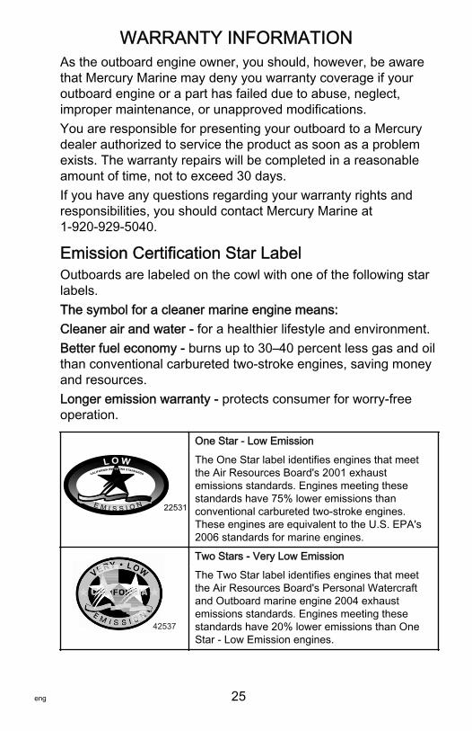
One Star ‑ Low Emission
The One Star label identifies engines that meetthe Air Resources Board's 2001 exhaustemissions standards. Engines meeting thesestandards have 75% lower emissions thanconventional carbureted two‑stroke engines.These engines are equivalent to the U.S. EPA's2006 standards for marine engines.
42537
Two Stars ‑ Very Low Emission
The Two Star label identifies engines that meetthe Air Resources Board's Personal Watercraftand Outboard marine engine 2004 exhaustemissions standards. Engines meeting thesestandards have 20% lower emissions than OneStar ‑ Low Emission engines.
WARRANTY INFORMATION
26 eng
42538
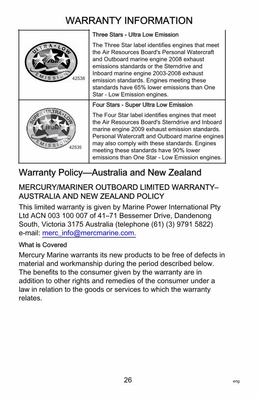
Three Stars ‑ Ultra Low Emission
The Three Star label identifies engines that meetthe Air Resources Board's Personal Watercraftand Outboard marine engine 2008 exhaustemissions standards or the Sterndrive andInboard marine engine 2003‑2008 exhaustemission standards. Engines meeting thesestandards have 65% lower emissions than OneStar ‑ Low Emission engines.
42539
Four Stars ‑ Super Ultra Low Emission
The Four Star label identifies engines that meetthe Air Resources Board's Sterndrive and Inboardmarine engine 2009 exhaust emission standards.Personal Watercraft and Outboard marine enginesmay also comply with these standards. Enginesmeeting these standards have 90% loweremissions than One Star ‑ Low Emission engines.
Warranty Policy—Australia and New ZealandMERCURY/MARINER OUTBOARD LIMITED WARRANTY–AUSTRALIA AND NEW ZEALAND POLICYThis limited warranty is given by Marine Power International PtyLtd ACN 003 100 007 of 41–71 Bessemer Drive, DandenongSouth, Victoria 3175 Australia (telephone (61) (3) 9791 5822)e‑mail: [email protected] is CoveredMercury Marine warrants its new products to be free of defects inmaterial and workmanship during the period described below.The benefits to the consumer given by the warranty are inaddition to other rights and remedies of the consumer under alaw in relation to the goods or services to which the warrantyrelates.
WARRANTY INFORMATION
eng 27
Guarantees Under Australian Consumer LawOur goods come with guarantees that cannot be excluded underthe Australian Consumer Law. You are entitled to a replacementor refund for a major failure and compensation for any otherreasonably foreseeable loss or damage. You are also entitled tohave the goods repaired or replaced if the goods fail to be ofacceptable quality and the failure does not amount to a majorfailure.Warranty Period for Recreational UseThis Limited Warranty provides coverage for three (3) years fromthe date the product is first sold to a recreational use retailpurchaser, or the date on which the product is first put intoservice, whichever occurs first. Unexpired warranty coveragecan be transferred to a subsequent recreational use customerupon proper registration of the product.Warranty Period for Commercial UseCommercial users of these products receive warranty coverageunder this Limited Warranty of one (1) year from the date of firstretail sale, or one (1) year from the date on which the productwas first put into service, whichever occurs first. Commercial useis defined as any work or employment related use of the product,or any use of the product which generates income, for any partof the warranty period, even if the product is only occasionallyused for such purposes. Unexpired warranty coverage cannot betransferred either to or from a commercial use customer.
WARRANTY INFORMATION
28 eng
Conditions That Must Be Met to Obtain Warranty CoverageWarranty coverage under this Limited Warranty is available onlyto retail customers that purchase from a Dealer authorized byMercury Marine to distribute the product in the country in whichthe sale occurred, and then only after the Mercury Marinespecified predelivery inspection process is completed anddocumented. Warranty coverage becomes available upon properregistration of the product by the authorized dealer. Inaccuratewarranty registration information regarding recreational use, orsubsequent change of use from recreational to commercial(unless properly registered) may void the warranty at the solediscretion of Mercury Marine. Routine maintenance outlined inthe Operation and Maintenance Manual must be timelyperformed in order to maintain warranty coverage. MercuryMarine reserves the right to make warranty coverage contingentupon proof of proper maintenance.What Mercury Will DoMercury Marine's sole and exclusive obligation under thisLimited Warranty is limited to, at our option, repairing a defectivepart, replacing such part or parts with new or Mercury Marinecertified remanufactured parts, or refunding the purchase price ofthe Mercury Marine product. Mercury Marine reserves the rightto improve or modify products from time to time withoutassuming an obligation to modify products previouslymanufactured.
WARRANTY INFORMATION
eng 29
How to Obtain Warranty Coverage Under This Limited WarrantyThe customer must provide Mercury Marine with a reasonableopportunity to repair and reasonable access to the product forwarranty service. Warranty claims shall be made by deliveringthe product for inspection to a Mercury Marine dealer authorizedto service the product. A list of dealers and their contact details isavailable at www.mercurymarine.com.au. If the purchaser cannotdeliver the product to such a dealer, written notice must be givento Mercury Marine at the address shown above. Mercury Marinewill then arrange for the inspection and any covered repair. ThisLimited Warranty will not cover the purchaser for all relatedtransportation charges and travel time. If the service provided isnot covered by this limited warranty, the purchaser shall pay forall related labor and material and any other expenses associatedwith that service, provided that a consumer will not be obligatedto pay where the service has been carried out to remedy a failureof an acceptable quality guarantee which is binding on MercuryMarine under the Australian Consumer Law. The purchaser shallnot, unless requested by Mercury Marine, ship the product orparts of the product directly to Mercury Marine. Proof ofregistered ownership must be presented to the dealer at the timewarranty service is requested in order to obtain coverage underthis Limited Warranty.
WARRANTY INFORMATION
30 eng
What is Not CoveredThis limited warranty does not cover routine maintenance items,tune‑ups, adjustments, normal wear and tear, damage causedby abuse, abnormal use, use of a propeller or gear ratio thatdoes not allow the engine to run in its recommended wide‑openthrottle RPM range (see the Operation and MaintenanceManual), operation of the product in a manner inconsistent withthe recommended operation/duty cycle section of the Operationand Maintenance Manual, neglect, accident, submersion,improper installation (proper installation specifications andtechniques are set forth in the installation instructions for theproduct), improper service, use of an accessory or part notmanufactured or sold by us, jet pump impellers and liners,operation with fuels, oils or lubricants which are not suitable foruse with the product (see the Operation and MaintenanceManual), alteration or removal of parts, water entering the enginethrough the fuel intake, air intake or exhaust system, or damageto the product from insufficient cooling water caused by blockageof the cooling system by a foreign body, running the engine outof water, mounting the engine too high on the transom, orrunning the boat with the engine trimmed out too far. Use of theproduct for racing or other competitive activity, or operating witha racing type lower unit, at any point, even by a prior owner ofthe product, voids the warranty.Expenses related to haul‑out, launch, towing, storage, telephone,rental, inconvenience, slip fees, insurance coverage, loanpayments, loss of time, loss of income, or any other type ofincidental or consequential damages are not covered by thisLimited Warranty. Also, expenses associated with the removaland/or replacement of boat partitions or material caused by boatdesign for access to the product are not covered by thiswarranty.
WARRANTY INFORMATION
eng 31
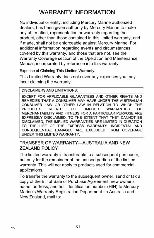
No individual or entity, including Mercury Marine authorizeddealers, has been given authority by Mercury Marine to makeany affirmation, representation or warranty regarding theproduct, other than those contained in this limited warranty, andif made, shall not be enforceable against Mercury Marine. Foradditional information regarding events and circumstancescovered by this warranty, and those that are not, see theWarranty Coverage section of the Operation and MaintenanceManual, incorporated by reference into this warranty.Expense of Claiming This Limited WarrantyThis Limited Warranty does not cover any expenses you mayincur claiming the warranty.
DISCLAIMERS AND LIMITATIONS:
EXCEPT FOR APPLICABLE GUARANTEES AND OTHER RIGHTS ANDREMEDIES THAT A CONSUMER MAY HAVE UNDER THE AUSTRALIANCONSUMER LAW OR OTHER LAW IN RELATION TO WHICH THEPRODUCTS RELATE, THE IMPLIED WARRANTIES OFMERCHANTABILITY AND FITNESS FOR A PARTICULAR PURPOSE AREEXPRESSLY DISCLAIMED. TO THE EXTENT THAT THEY CANNOT BEDISCLAIMED, THE IMPLIED WARRANTIES ARE LIMITED IN DURATIONTO THE LIFE OF THE EXPRESS WARRANTY. INCIDENTAL ANDCONSEQUENTIAL DAMAGES ARE EXCLUDED FROM COVERAGEUNDER THIS LIMITED WARRANTY.
TRANSFER OF WARRANTY—AUSTRALIA AND NEWZEALAND POLICYThe limited warranty is transferable to a subsequent purchaser,but only for the remainder of the unused portion of the limitedwarranty. This will not apply to products used for commercialapplications.To transfer the warranty to the subsequent owner, send or fax acopy of the Bill of Sale or Purchase Agreement, new owner’sname, address, and hull identification number (HIN) to MercuryMarine’s Warranty Registration Department. In Australia andNew Zealand, mail to:
WARRANTY INFORMATION
32 eng
Mercury MarineAttn: Warranty Registration DepartmentBrunswick Asia Pacific GroupPrivate Bag 1420Dandenong South, Victoria 3164Australia
Upon processing the transfer of warranty, Mercury Marine willsend registration verification to the new owner of the product bymail. There is no charge for this service.You may change your address at any time, including at the timeof the warranty claim, by calling Mercury Marine or sending aletter or fax with your name, old address, new address, and hullidentification number (HIN) to Mercury Marine’s WarrantyRegistration Department.
GENERAL INFORMATION
eng 33
Boater's ResponsibilitiesThe operator (driver) is responsible for the correct and safeoperation of the boat and the safety of its occupants and generalpublic. It is strongly recommended that each operator read andunderstand this entire manual before operating the outboard.Be sure that at least one additional person onboard is instructedin the basics of starting and operating the outboard and boathandling in case the driver is unable to operate the boat.
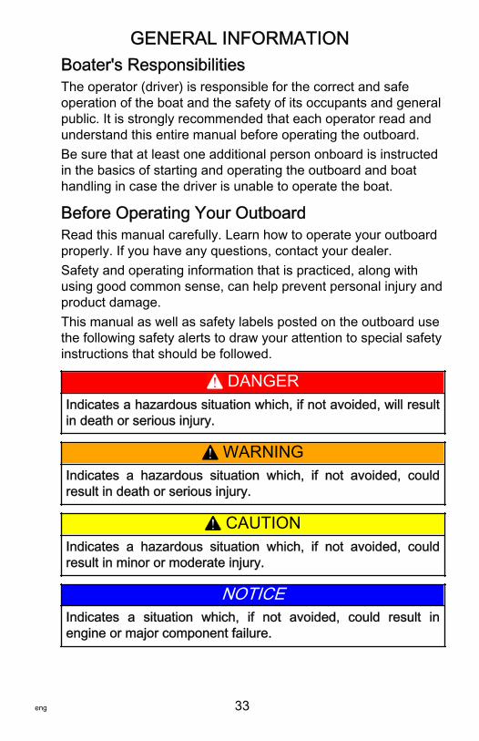
Before Operating Your OutboardRead this manual carefully. Learn how to operate your outboardproperly. If you have any questions, contact your dealer.Safety and operating information that is practiced, along withusing good common sense, can help prevent personal injury andproduct damage.This manual as well as safety labels posted on the outboard usethe following safety alerts to draw your attention to special safetyinstructions that should be followed.
! DANGERIndicates a hazardous situation which, if not avoided, will resultin death or serious injury.
! WARNINGIndicates a hazardous situation which, if not avoided, couldresult in death or serious injury.
! CAUTIONIndicates a hazardous situation which, if not avoided, couldresult in minor or moderate injury.
NOTICEIndicates a situation which, if not avoided, could result inengine or major component failure.
GENERAL INFORMATION
34 eng
Boat Horsepower Capacity
! WARNINGExceeding the boat's maximum horsepower rating can causeserious injury or death. Overpowering the boat can affect boatcontrol and flotation characteristics or break the transom. Donot install an engine that exceeds the boat's maximum powerrating.
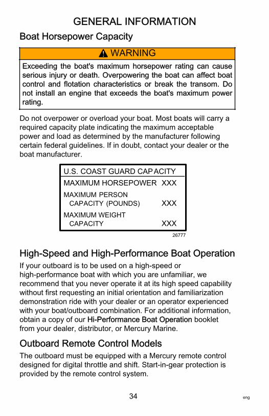
Do not overpower or overload your boat. Most boats will carry arequired capacity plate indicating the maximum acceptablepower and load as determined by the manufacturer followingcertain federal guidelines. If in doubt, contact your dealer or theboat manufacturer.
U.S. COAST GUARD CAPACITYMAXIMUM HORSEPOWER XXXMAXIMUM PERSON CAPACITY (POUNDS) XXXMAXIMUM WEIGHT CAPACITY XXX
26777
High‑Speed and High‑Performance Boat OperationIf your outboard is to be used on a high‑speed orhigh‑performance boat with which you are unfamiliar, werecommend that you never operate it at its high speed capabilitywithout first requesting an initial orientation and familiarizationdemonstration ride with your dealer or an operator experiencedwith your boat/outboard combination. For additional information,obtain a copy of our Hi‑Performance Boat Operation bookletfrom your dealer, distributor, or Mercury Marine.
Outboard Remote Control ModelsThe outboard must be equipped with a Mercury remote controldesigned for digital throttle and shift. Start‑in‑gear protection isprovided by the remote control system.
GENERAL INFORMATION
eng 35
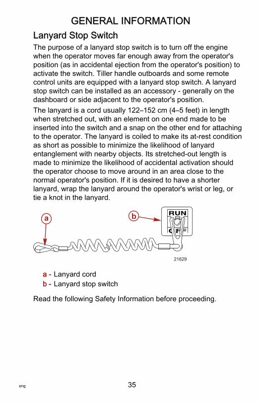
Lanyard Stop SwitchThe purpose of a lanyard stop switch is to turn off the enginewhen the operator moves far enough away from the operator'sposition (as in accidental ejection from the operator's position) toactivate the switch. Tiller handle outboards and some remotecontrol units are equipped with a lanyard stop switch. A lanyardstop switch can be installed as an accessory ‑ generally on thedashboard or side adjacent to the operator's position.The lanyard is a cord usually 122–152 cm (4–5 feet) in lengthwhen stretched out, with an element on one end made to beinserted into the switch and a snap on the other end for attachingto the operator. The lanyard is coiled to make its at‑rest conditionas short as possible to minimize the likelihood of lanyardentanglement with nearby objects. Its stretched‑out length ismade to minimize the likelihood of accidental activation shouldthe operator choose to move around in an area close to thenormal operator's position. If it is desired to have a shorterlanyard, wrap the lanyard around the operator's wrist or leg, ortie a knot in the lanyard.
a - Lanyard cordb - Lanyard stop switch
Read the following Safety Information before proceeding.
21629
a b
GENERAL INFORMATION
36 eng
Important Safety Information: The purpose of a lanyard stopswitch is to stop the engine when the operator moves far enoughaway from the operator's position to activate the switch. Thiswould occur if the operator accidentally falls overboard or moveswithin the boat a sufficient distance from the operator's position.Falling overboard and accidental ejections are more likely tooccur in certain types of boats such as low sided inflatables,bass boats, high performance boats, and light, sensitive handlingfishing boats operated by a hand tiller. Falling overboard andaccidental ejections are also likely to occur as a result of pooroperating practices such as sitting on the back of the seat orgunwale at planing speeds, standing at planing speeds, sittingon elevated fishing boat decks, operating at planing speeds inshallow or obstacle infested waters, releasing your grip on asteering wheel or tiller handle that is pulling in one direction,drinking alcohol or consuming drugs, or daring high speed boatmaneuvers.While activation of the lanyard stop switch will stop the engineimmediately, a boat will continue to coast for some distancedepending upon the velocity and degree of any turn at shutdown. However, the boat will not complete a full circle. While theboat is coasting, it can cause injury to anyone in the boat's pathas seriously as the boat would when under power.We strongly recommend that other occupants be instructed onproper starting and operating procedures should they berequired to operate the engine in an emergency (if the operatoris accidentally ejected).
! WARNINGIf the operator falls out of the boat, stop the engine immediatelyto reduce the possibility of serious injury or death from beingstruck by the boat. Always properly connect the operator to thestop switch using a lanyard.
GENERAL INFORMATION
eng 37
! WARNINGAvoid serious injury or death from deceleration forces resultingfrom accidental or unintended stop switch activation. The boatoperator should never leave the operator's station without firstdisconnecting the stop switch lanyard from the operator.
Accidental or unintended activation of the switch during normaloperation is also a possibility. This could cause any, or all, of thefollowing potentially hazardous situations:• Occupants could be thrown forward due to unexpected loss
of forward motion ‑ a particular concern for passengers inthe front of the boat who could be ejected over the bow andpossibly struck by the gearcase or propeller.
• Loss of power and directional control in heavy seas, strongcurrent, or high winds.
• Loss of control when docking.
KEEP THE LANYARD STOP SWITCH AND LANYARDCORD IN GOOD OPERATING CONDITIONBefore each use, check to ensure the lanyard stop switch worksproperly. Start the engine and stop it by pulling the lanyard cord.If the engine does not stop, have the switch repaired beforeoperating the boat.Before each use, visually inspect the lanyard cord to ensure it isin good working condition and that there are no breaks, cuts, orwear to the cord. Check that the clips on the ends of the cord arein good condition. Replace any damaged or worn lanyard cords.
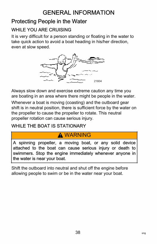
GENERAL INFORMATION
38 eng
Protecting People in the WaterWHILE YOU ARE CRUISINGIt is very difficult for a person standing or floating in the water totake quick action to avoid a boat heading in his/her direction,even at slow speed.
21604
Always slow down and exercise extreme caution any time youare boating in an area where there might be people in the water.Whenever a boat is moving (coasting) and the outboard gearshift is in neutral position, there is sufficient force by the water onthe propeller to cause the propeller to rotate. This neutralpropeller rotation can cause serious injury.
WHILE THE BOAT IS STATIONARY
! WARNINGA spinning propeller, a moving boat, or any solid deviceattached to the boat can cause serious injury or death toswimmers. Stop the engine immediately whenever anyone inthe water is near your boat.
Shift the outboard into neutral and shut off the engine beforeallowing people to swim or be in the water near your boat.
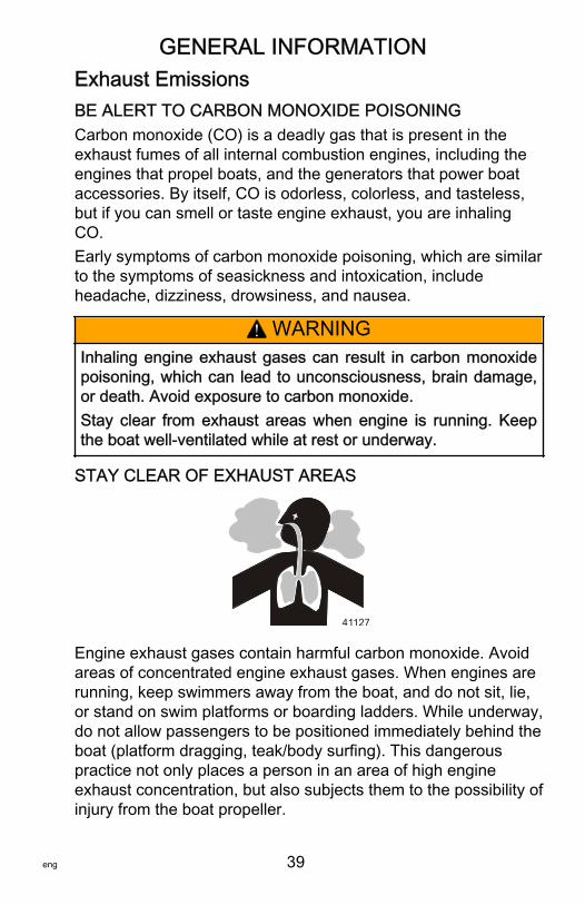
GENERAL INFORMATION
eng 39
Exhaust EmissionsBE ALERT TO CARBON MONOXIDE POISONINGCarbon monoxide (CO) is a deadly gas that is present in theexhaust fumes of all internal combustion engines, including theengines that propel boats, and the generators that power boataccessories. By itself, CO is odorless, colorless, and tasteless,but if you can smell or taste engine exhaust, you are inhalingCO.Early symptoms of carbon monoxide poisoning, which are similarto the symptoms of seasickness and intoxication, includeheadache, dizziness, drowsiness, and nausea.
! WARNINGInhaling engine exhaust gases can result in carbon monoxidepoisoning, which can lead to unconsciousness, brain damage,or death. Avoid exposure to carbon monoxide.Stay clear from exhaust areas when engine is running. Keepthe boat well‑ventilated while at rest or underway.
STAY CLEAR OF EXHAUST AREAS
41127
Engine exhaust gases contain harmful carbon monoxide. Avoidareas of concentrated engine exhaust gases. When engines arerunning, keep swimmers away from the boat, and do not sit, lie,or stand on swim platforms or boarding ladders. While underway,do not allow passengers to be positioned immediately behind theboat (platform dragging, teak/body surfing). This dangerouspractice not only places a person in an area of high engineexhaust concentration, but also subjects them to the possibility ofinjury from the boat propeller.
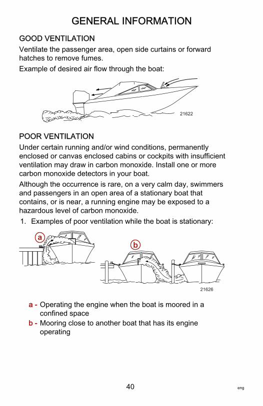
GENERAL INFORMATION
40 eng
GOOD VENTILATIONVentilate the passenger area, open side curtains or forwardhatches to remove fumes.Example of desired air flow through the boat:
21622
POOR VENTILATIONUnder certain running and/or wind conditions, permanentlyenclosed or canvas enclosed cabins or cockpits with insufficientventilation may draw in carbon monoxide. Install one or morecarbon monoxide detectors in your boat.Although the occurrence is rare, on a very calm day, swimmersand passengers in an open area of a stationary boat thatcontains, or is near, a running engine may be exposed to ahazardous level of carbon monoxide.1. Examples of poor ventilation while the boat is stationary:
a - Operating the engine when the boat is moored in aconfined space
b - Mooring close to another boat that has its engineoperating
21626
ab
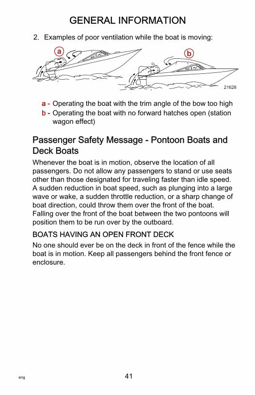
GENERAL INFORMATION
eng 41
2. Examples of poor ventilation while the boat is moving:
a - Operating the boat with the trim angle of the bow too highb - Operating the boat with no forward hatches open (station
wagon effect)
Passenger Safety Message ‑ Pontoon Boats andDeck BoatsWhenever the boat is in motion, observe the location of allpassengers. Do not allow any passengers to stand or use seatsother than those designated for traveling faster than idle speed.A sudden reduction in boat speed, such as plunging into a largewave or wake, a sudden throttle reduction, or a sharp change ofboat direction, could throw them over the front of the boat.Falling over the front of the boat between the two pontoons willposition them to be run over by the outboard.
BOATS HAVING AN OPEN FRONT DECKNo one should ever be on the deck in front of the fence while theboat is in motion. Keep all passengers behind the front fence orenclosure.
a b
21628
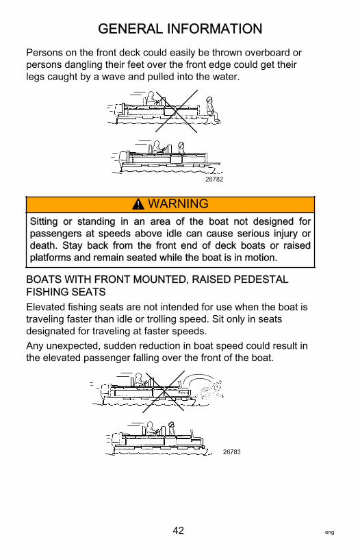
GENERAL INFORMATION
42 eng
Persons on the front deck could easily be thrown overboard orpersons dangling their feet over the front edge could get theirlegs caught by a wave and pulled into the water.
26782
! WARNINGSitting or standing in an area of the boat not designed forpassengers at speeds above idle can cause serious injury ordeath. Stay back from the front end of deck boats or raisedplatforms and remain seated while the boat is in motion.
BOATS WITH FRONT MOUNTED, RAISED PEDESTALFISHING SEATSElevated fishing seats are not intended for use when the boat istraveling faster than idle or trolling speed. Sit only in seatsdesignated for traveling at faster speeds.Any unexpected, sudden reduction in boat speed could result inthe elevated passenger falling over the front of the boat.
26783
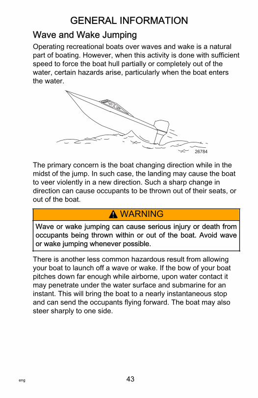
GENERAL INFORMATION
eng 43
Wave and Wake JumpingOperating recreational boats over waves and wake is a naturalpart of boating. However, when this activity is done with sufficientspeed to force the boat hull partially or completely out of thewater, certain hazards arise, particularly when the boat entersthe water.
26784
The primary concern is the boat changing direction while in themidst of the jump. In such case, the landing may cause the boatto veer violently in a new direction. Such a sharp change indirection can cause occupants to be thrown out of their seats, orout of the boat.
! WARNINGWave or wake jumping can cause serious injury or death fromoccupants being thrown within or out of the boat. Avoid waveor wake jumping whenever possible.
There is another less common hazardous result from allowingyour boat to launch off a wave or wake. If the bow of your boatpitches down far enough while airborne, upon water contact itmay penetrate under the water surface and submarine for aninstant. This will bring the boat to a nearly instantaneous stopand can send the occupants flying forward. The boat may alsosteer sharply to one side.
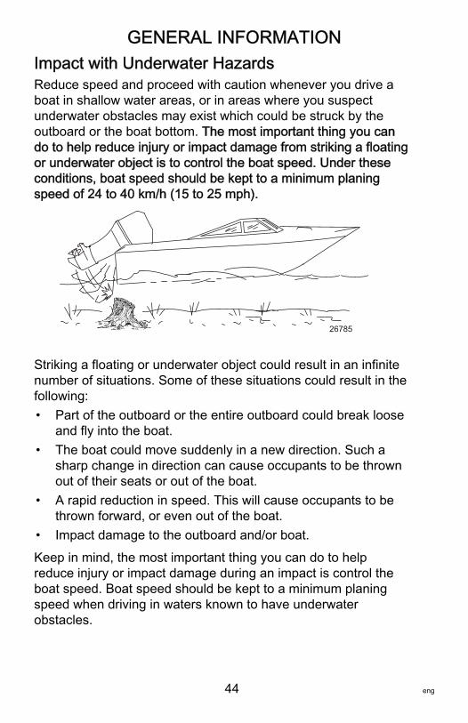
GENERAL INFORMATION
44 eng
Impact with Underwater HazardsReduce speed and proceed with caution whenever you drive aboat in shallow water areas, or in areas where you suspectunderwater obstacles may exist which could be struck by theoutboard or the boat bottom. The most important thing you cando to help reduce injury or impact damage from striking a floatingor underwater object is to control the boat speed. Under theseconditions, boat speed should be kept to a minimum planingspeed of 24 to 40 km/h (15 to 25 mph).
26785
Striking a floating or underwater object could result in an infinitenumber of situations. Some of these situations could result in thefollowing:• Part of the outboard or the entire outboard could break loose
and fly into the boat.• The boat could move suddenly in a new direction. Such a
sharp change in direction can cause occupants to be thrownout of their seats or out of the boat.
• A rapid reduction in speed. This will cause occupants to bethrown forward, or even out of the boat.
• Impact damage to the outboard and/or boat.
Keep in mind, the most important thing you can do to helpreduce injury or impact damage during an impact is control theboat speed. Boat speed should be kept to a minimum planingspeed when driving in waters known to have underwaterobstacles.
GENERAL INFORMATION
eng 45
After striking a submerged object, stop the engine as soon aspossible and inspect it for any broken or loose parts. If damageis present or suspected, the outboard should be taken to anauthorized dealer for a thorough inspection and necessaryrepair.The boat should also be checked for any hull fractures, transomfractures, or water leaks.Operating a damaged outboard could cause additional damageto other parts of the outboard, or could affect control of the boat.If continued running is necessary, do so at greatly reducedspeeds.
! WARNINGOperating a boat or engine with impact damage can result inproduct damage, serious injury, or death. If the vesselexperiences any form of impact, have an authorized MercuryMarine dealer inspect and repair the vessel or power package.
Selecting Accessories for Your OutboardGenuine Mercury Precision or Quicksilver Accessories havebeen specifically designed and tested for your outboard. Theseaccessories are available from Mercury Marine dealers.IMPORTANT: Check with your dealer before installingaccessories. The misuse of approved accessories or the use ofnonapproved accessories can damage the product.Some accessories not manufactured or sold by Mercury Marineare not designed to be safely used with your outboard oroutboard operating system. Acquire and read the installation,operation and maintenance manuals for all your selectedaccessories.
Safe Boating RecommendationsTo safely enjoy the waterways, familiarize yourself with local andall other governmental boating regulations and restrictions andconsider the following suggestions.Know and obey all nautical rules and laws of the waterways.
GENERAL INFORMATION
46 eng
• We recommend that all powerboat operators complete aboating safety course. In the U.S., the U.S. Coast GuardAuxiliary, the Power Squadron, the Red Cross, and yourstate or provincial boating law enforcement agency providecourses. For more information in the U.S., call the Boat U.S.Foundation at 1‑800‑336‑BOAT (2628).
Perform safety checks and required maintenance.• Follow a regular schedule and ensure that all repairs are
properly made.
Check safety equipment onboard.• Here are some suggestions of the types of safety equipment
to carry when boating:Approved fire extinguishersSignal devices: flashlight, rockets or flares, flag, andwhistle or hornTools necessary for minor repairsAnchor and extra anchor lineManual bilge pump and extra drain plugsDrinking waterRadioPaddle or oarSpare propeller, thrust hubs, and an appropriate wrenchFirst aid kit and instructionsWaterproof storage containersSpare operating equipment, batteries, bulbs, and fusesCompass and map or chart of the areaPersonal flotation device (one per person onboard)
Watch for signs of weather change and avoid foul weatherand rough‑sea boating.Tell someone where you are going and when you expect toreturn.Passenger boarding.
GENERAL INFORMATION
eng 47
• Stop the engine whenever passengers are boarding,unloading, or are near the back (stern) of the boat. Shiftingthe drive unit into neutral is not sufficient.
Use personal flotation devices.• Federal law requires that there be a U.S. Coast
Guard‑approved life jacket (personal flotation device),correctly sized and readily accessible for every persononboard, plus a throwable cushion or ring. We stronglyadvise that everyone wear a life jacket at all times while inthe boat.
Prepare other boat operators.• Instruct at least one person onboard in the basics of starting
and operating the engine and boat handling in case thedriver becomes disabled or falls overboard.
Do not overload your boat.• Most boats are rated and certified for maximum load
(weight) capacities (refer to your boat capacity plate). Knowyour boat's operating and loading limitations. Know if yourboat will float if it is full of water. When in doubt, contact yourauthorized Mercury Marine dealer or the boat manufacturer.
Ensure that everyone in the boat is properly seated.• Do not allow anyone to sit or ride on any part of the boat that
was not intended for such use. This includes the backs ofseats, gunwales, transom, bow, decks, raised fishing seats,and any rotating fishing seat. Passengers should not sit orride anywhere that sudden unexpected acceleration, suddenstopping, unexpected loss of boat control, or sudden boatmovement could cause a person to be thrown overboard orinto the boat. Ensure that all passengers have a proper seatand are in it before any boat movement.
Never operate a boat while under the influence of alcohol ordrugs. It is the law.• Alcohol or drugs can impair your judgment and greatly
reduce your ability to react quickly.
Know your boating area and avoid hazardous locations.
GENERAL INFORMATION
48 eng
Be alert.• The operator of the boat is responsible by law to maintain a
proper lookout by sight and hearing. The operator musthave an unobstructed view particularly to the front. Nopassengers, load, or fishing seats should block theoperator's view when the boat is above idle or planingtransition speed. Watch out for others, the water, and yourwake.
Never drive your boat directly behind a water skier.• Your boat traveling at 40 km/h (25 mph) will overtake a
fallen skier who is 61 m (200 ft) in front of you in fiveseconds.
Watch fallen skiers.• When using your boat for waterskiing or similar activities,
always keep a fallen or down skier on the operator's side ofthe boat while returning to attend to the skier. The operatorshould always have the down skier in sight and never backup to the skier or anyone in the water.
Report accidents.• Boat operators are required by law to file a boating accident
report with their state boating law enforcement agency whentheir boat is involved in certain boating accidents. A boatingaccident must be reported if 1) there is loss of life orprobable loss of life, 2) there is personal injury requiringmedical treatment beyond first aid, 3) there is damage toboats or other property where the damage value exceeds$500.00, or 4) there is complete loss of the boat. Seekfurther assistance from local law enforcement.
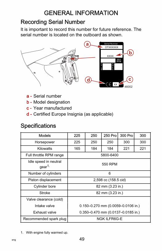
GENERAL INFORMATION
eng 49
Recording Serial NumberIt is important to record this number for future reference. Theserial number is located on the outboard as shown.
a - Serial numberb - Model designationc - Year manufacturedd - Certified Europe Insignia (as applicable)
SpecificationsModels 225 250 250 Pro 300 Pro 300
Horsepower 225 250 250 300 300
Kilowatts 165 184 184 221 221
Full throttle RPM range 5800‑6400
Idle speed in neutralgear1. 550 RPM
Number of cylinders 6
Piston displacement 2,598 cc (158.5 cid)
Cylinder bore 82 mm (3.23 in.)
Stroke 82 mm (3.23 in.)
Valve clearance (cold)
Intake valve 0.150–0.270 mm (0.0059–0.0106 in.)
Exhaust valve 0.350–0.470 mm (0.0137–0.0185 in.)
Recommended spark plug NGK ILFR6G‑E
XX
OTXXXXXX
XXXX
a
b
cd46002
1. With engine fully warmed up.
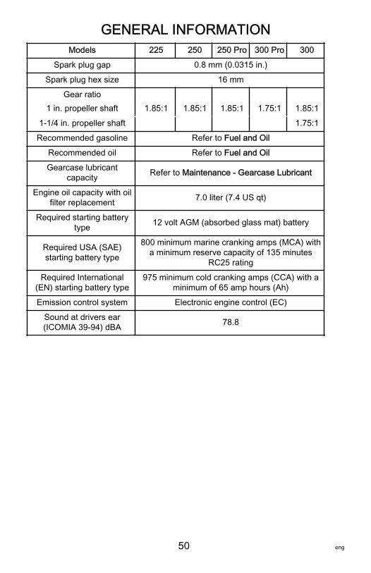
GENERAL INFORMATION
50 eng
Models 225 250 250 Pro 300 Pro 300
Spark plug gap 0.8 mm (0.0315 in.)
Spark plug hex size 16 mm
Gear ratio1 in. propeller shaft 1.85:1 1.85:1 1.85:1 1.75:1 1.85:1
1‑1/4 in. propeller shaft 1.75:1
Recommended gasoline Refer to Fuel and Oil
Recommended oil Refer to Fuel and Oil
Gearcase lubricantcapacity Refer to Maintenance ‑ Gearcase Lubricant
Engine oil capacity with oilfilter replacement 7.0 liter (7.4 US qt)
Required starting batterytype 12 volt AGM (absorbed glass mat) battery
Required USA (SAE)starting battery type
800 minimum marine cranking amps (MCA) witha minimum reserve capacity of 135 minutes
RC25 rating
Required International(EN) starting battery type
975 minimum cold cranking amps (CCA) with aminimum of 65 amp hours (Ah)
Emission control system Electronic engine control (EC)
Sound at drivers ear(ICOMIA 39‑94) dBA 78.8
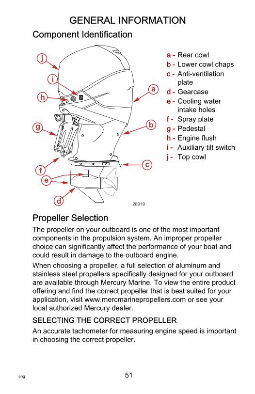
GENERAL INFORMATION
eng 51
Component Identification
a - Rear cowlb - Lower cowl chapsc - Anti‑ventilation
plated - Gearcasee - Cooling water
intake holesf - Spray plateg - Pedestalh - Engine flushi - Auxiliary tilt switchj - Top cowl
Propeller SelectionThe propeller on your outboard is one of the most importantcomponents in the propulsion system. An improper propellerchoice can significantly affect the performance of your boat andcould result in damage to the outboard engine.When choosing a propeller, a full selection of aluminum andstainless steel propellers specifically designed for your outboardare available through Mercury Marine. To view the entire productoffering and find the correct propeller that is best suited for yourapplication, visit www.mercmarinepropellers.com or see yourlocal authorized Mercury dealer.
SELECTING THE CORRECT PROPELLERAn accurate tachometer for measuring engine speed is importantin choosing the correct propeller.
j
i
h
g
fe
d
c
b
a
28919
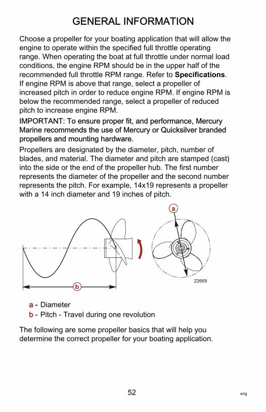
GENERAL INFORMATION
52 eng
Choose a propeller for your boating application that will allow theengine to operate within the specified full throttle operatingrange. When operating the boat at full throttle under normal loadconditions, the engine RPM should be in the upper half of therecommended full throttle RPM range. Refer to Specifications.If engine RPM is above that range, select a propeller ofincreased pitch in order to reduce engine RPM. If engine RPM isbelow the recommended range, select a propeller of reducedpitch to increase engine RPM.IMPORTANT: To ensure proper fit, and performance, MercuryMarine recommends the use of Mercury or Quicksilver brandedpropellers and mounting hardware.Propellers are designated by the diameter, pitch, number ofblades, and material. The diameter and pitch are stamped (cast)into the side or the end of the propeller hub. The first numberrepresents the diameter of the propeller and the second numberrepresents the pitch. For example, 14x19 represents a propellerwith a 14 inch diameter and 19 inches of pitch.
a - Diameterb - Pitch ‑ Travel during one revolution
The following are some propeller basics that will help youdetermine the correct propeller for your boating application.
a
b22669
GENERAL INFORMATION
eng 53
Diameter ‑ The diameter is the distance across the imaginarycircle that is made when the propeller rotates. The correctdiameter for each propeller has been predetermined for thedesign of your outboard. However, when more than onediameter is available for the same pitch, use a larger diameter forheavy boat applications and a smaller diameter for lighterapplications.Pitch ‑ The pitch is the theoretical distance, in inches, that apropeller travels forward during one revolution. Pitch can bethought of similar to gears in a car. The lower the gear, the fasterthe car will accelerate, but with lower overall top speed.Likewise, a lower pitch propeller will accelerate quickly, buttop‑end speed will be reduced. The higher the propeller pitch thefaster the boat will usually go; though typically slowingacceleration.Determining the correct pitch size ‑ First, check the full throttleRPM under normal load condition. If the full throttle RPM iswithin the recommended range, select a replacement or upgradepropeller with the same pitch as the current propeller.• Adding 1 inch of pitch will reduce the full throttle RPM by
150 to 200• Subtracting 1 inch of pitch will increase full throttle RPM by
150 to 200• Upgrading from a 3‑blade propeller to a 4‑blade propeller
will generally decrease full throttle RPM by 50 to 100
IMPORTANT: Avoid damage to the engine. Never use apropeller which allows the engine to exceed the recommendedfull throttle RPM range when under normal full throttle operation.
GENERAL INFORMATION
54 eng
PROPELLER MATERIALMost propellers manufactured by Mercury Marine are made fromeither aluminum or stainless steel. Aluminum is suitable forgeneral purpose use and is standard equipment on many newboats. Stainless steel is over five times more durable thanaluminum and typically provides performance gains inacceleration and top end speed due to design efficiencies.Stainless steel propellers also come in a larger variety of sizesand styles that allow you to dial in the ultimate performance foryour boat.
3 BLADE VS. 4 BLADEAvailable in many sizes of both aluminum and stainless, 3 and4‑blade propellers have unique performance characteristics. Ingeneral, 3‑blade propellers offer good all around performanceand higher top speed than 4‑blade propellers. However, 4‑bladepropellers are usually faster to plane and more efficient atcruising speeds, but lack the top end speed of a 3‑bladepropeller.
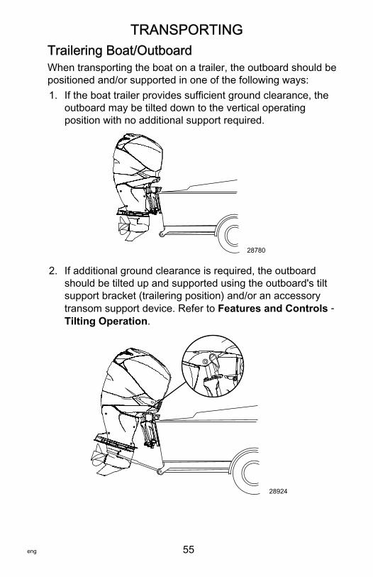
TRANSPORTING
eng 55
Trailering Boat/OutboardWhen transporting the boat on a trailer, the outboard should bepositioned and/or supported in one of the following ways:1. If the boat trailer provides sufficient ground clearance, the
outboard may be tilted down to the vertical operatingposition with no additional support required.
28780
2. If additional ground clearance is required, the outboardshould be tilted up and supported using the outboard's tiltsupport bracket (trailering position) and/or an accessorytransom support device. Refer to Features and Controls ‑Tilting Operation.
28924
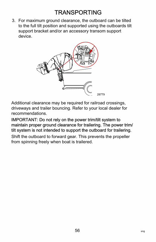
TRANSPORTING
56 eng
3. For maximum ground clearance, the outboard can be tiltedto the full tilt position and supported using the outboards tiltsupport bracket and/or an accessory transom supportdevice.
28779
Additional clearance may be required for railroad crossings,driveways and trailer bouncing. Refer to your local dealer forrecommendations.IMPORTANT: Do not rely on the power trim/tilt system tomaintain proper ground clearance for trailering. The power trim/tilt system is not intended to support the outboard for trailering.Shift the outboard to forward gear. This prevents the propellerfrom spinning freely when boat is trailered.
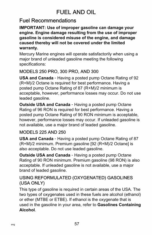
FUEL AND OIL
eng 57
Fuel RecommendationsIMPORTANT: Use of improper gasoline can damage yourengine. Engine damage resulting from the use of impropergasoline is considered misuse of the engine, and damagecaused thereby will not be covered under the limitedwarranty.Mercury Marine engines will operate satisfactorily when using amajor brand of unleaded gasoline meeting the followingspecifications:
MODELS 250 PRO, 300 PRO, AND 300USA and Canada ‑ Having a posted pump Octane Rating of 92(R+M)/2 Octane is required for best performance. Having aposted pump Octane Rating of 87 (R+M)/2 minimum isacceptable, however, performance losses may occur. Do not useleaded gasoline.Outside USA and Canada ‑ Having a posted pump OctaneRating of 96 RON is required for best performance. Having aposted pump Octane Rating of 90 RON minimum is acceptable,however, performance losses may occur. If unleaded gasoline isnot available, use a major brand of leaded gasoline.
MODELS 225 AND 250USA and Canada ‑ Having a posted pump Octane Rating of 87(R+M)/2 minimum. Premium gasoline [92 (R+M)/2 Octane] isalso acceptable. Do not use leaded gasoline.Outside USA and Canada ‑ Having a posted pump OctaneRating of 90 RON minimum. Premium gasoline (98 RON) is alsoacceptable. If unleaded gasoline is not available, use a majorbrand of leaded gasoline.
USING REFORMULATED (OXYGENATED) GASOLINES(USA ONLY)This type of gasoline is required in certain areas of the USA. Thetwo types of oxygenates used in these fuels are alcohol (ethanol)or ether (MTBE or ETBE). If ethanol is the oxygenate that isused in the gasoline in your area, refer to Gasolines ContainingAlcohol.
FUEL AND OIL
58 eng
These reformulated gasolines are acceptable for use in yourMercury Marine engine.
GASOLINES CONTAINING ALCOHOLIf the gasoline in your area contains either methanol (methylalcohol) or ethanol (ethyl alcohol), you should be aware ofcertain adverse effects that can occur. These adverse effects aremore severe with methanol. Increasing the percentage of alcoholin the fuel can also worsen these adverse effects.Some of these adverse effects are caused because the alcoholin the gasoline can absorb moisture from the air, resulting in aseparation of the water/alcohol from the gasoline in the fuel tank.The fuel system components on your Mercury Marine engine willwithstand up to 10% alcohol content in the gasoline. We do notknow what percentage your boat's fuel system will withstand.Contact your boat manufacturer for specific recommendations onthe boat's fuel system components (fuel tanks, fuel lines, andfittings). Be aware that gasolines containing alcohol may causeincreased:• Corrosion of metal parts• Deterioration of rubber or plastic parts• Fuel permeation through rubber fuel lines• Starting and operating difficulties
! WARNINGFuel leakage is a fire or explosion hazard, which can causeserious injury or death. Periodically inspect all fuel systemcomponents for leaks, softening, hardening, swelling, orcorrosion, particularly after storage. Any sign of leakage ordeterioration requires replacement before further engineoperation.
Because of possible adverse effects of alcohol in gasoline, it isrecommended that only alcohol‑free gasoline be used wherepossible. If only fuel containing alcohol is available, or if thepresence of alcohol is unknown, increased inspection frequencyfor leaks and abnormalities is required.
FUEL AND OIL
eng 59
IMPORTANT: When operating a Mercury Marine engine ongasoline containing alcohol, storage of gasoline in the fuel tankfor long periods should be avoided. Long periods of storage,common to boats, create unique problems. In cars, alcohol‑blendfuels normally are consumed before they can absorb enoughmoisture to cause trouble, but boats often sit idle long enough forphase separation to take place. In addition, internal corrosionmay take place during storage if alcohol has washed protectiveoil films from internal components.
Low Permeation Fuel Hose RequirementRequired for outboards manufactured for sale, sold, or offeredfor sale in the United States.• The Environmental Protection Agency (EPA) requires that
any outboard manufactured after January 1, 2009, must uselow permeation fuel hose for the primary fuel hoseconnecting the fuel tank to the outboard.
• Low permeation hose is USCG Type B1‑15 or Type A1‑15,defined as not exceeding 15/gm²/24 h with CE 10 fuel at23 °C as specified in SAE J 1527 ‑ marine fuel hose.
EPA Pressurized Portable Fuel TankRequirementsThe Environmental Protection Agency (EPA) requires portablefuel systems that are produced after January 1, 2011, for usewith outboard engines to remain fully sealed (pressurized) up to34.4 kPa (5.0 psi). These tanks may contain the following:• An air inlet that opens to allow air to enter as the fuel is
drawn out of the tank.• An air outlet that opens (vents) to the atmosphere if
pressure exceeds 34.4 kPa (5.0 psi).
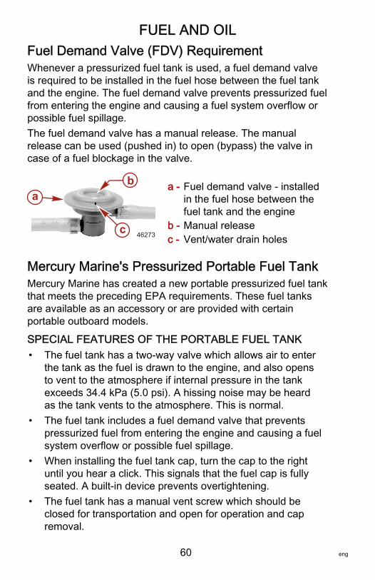
FUEL AND OIL
60 eng
Fuel Demand Valve (FDV) RequirementWhenever a pressurized fuel tank is used, a fuel demand valveis required to be installed in the fuel hose between the fuel tankand the engine. The fuel demand valve prevents pressurized fuelfrom entering the engine and causing a fuel system overflow orpossible fuel spillage.The fuel demand valve has a manual release. The manualrelease can be used (pushed in) to open (bypass) the valve incase of a fuel blockage in the valve.
a - Fuel demand valve ‑ installedin the fuel hose between thefuel tank and the engine
b - Manual releasec - Vent/water drain holes
Mercury Marine's Pressurized Portable Fuel TankMercury Marine has created a new portable pressurized fuel tankthat meets the preceding EPA requirements. These fuel tanksare available as an accessory or are provided with certainportable outboard models.
SPECIAL FEATURES OF THE PORTABLE FUEL TANK• The fuel tank has a two‑way valve which allows air to enter
the tank as the fuel is drawn to the engine, and also opensto vent to the atmosphere if internal pressure in the tankexceeds 34.4 kPa (5.0 psi). A hissing noise may be heardas the tank vents to the atmosphere. This is normal.
• The fuel tank includes a fuel demand valve that preventspressurized fuel from entering the engine and causing a fuelsystem overflow or possible fuel spillage.
• When installing the fuel tank cap, turn the cap to the rightuntil you hear a click. This signals that the fuel cap is fullyseated. A built‑in device prevents overtightening.
• The fuel tank has a manual vent screw which should beclosed for transportation and open for operation and capremoval.
a
c
b
46273
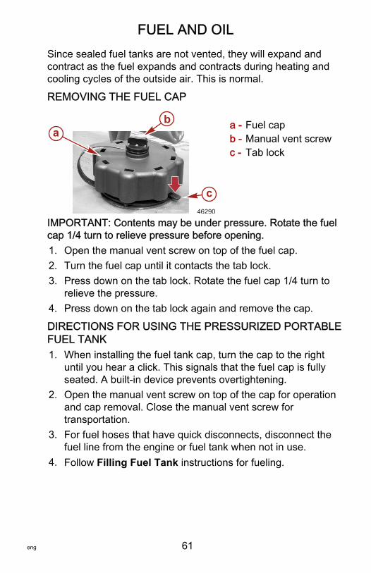
FUEL AND OIL
eng 61
Since sealed fuel tanks are not vented, they will expand andcontract as the fuel expands and contracts during heating andcooling cycles of the outside air. This is normal.
REMOVING THE FUEL CAP
a - Fuel capb - Manual vent screwc - Tab lock
IMPORTANT: Contents may be under pressure. Rotate the fuelcap 1/4 turn to relieve pressure before opening.1. Open the manual vent screw on top of the fuel cap.2. Turn the fuel cap until it contacts the tab lock.3. Press down on the tab lock. Rotate the fuel cap 1/4 turn to
relieve the pressure.4. Press down on the tab lock again and remove the cap.
DIRECTIONS FOR USING THE PRESSURIZED PORTABLEFUEL TANK1. When installing the fuel tank cap, turn the cap to the right
until you hear a click. This signals that the fuel cap is fullyseated. A built‑in device prevents overtightening.
2. Open the manual vent screw on top of the cap for operationand cap removal. Close the manual vent screw fortransportation.
3. For fuel hoses that have quick disconnects, disconnect thefuel line from the engine or fuel tank when not in use.
4. Follow Filling Fuel Tank instructions for fueling.
ab
c46290
FUEL AND OIL
62 eng
Filling Fuel Tank
! WARNINGAvoid serious injury or death from a gasoline fire or explosion.Use caution when filling fuel tanks. Always stop the engine anddo not smoke or allow open flames or sparks in the area whilefilling fuel tanks.
Fill the fuel tanks outdoors away from heat, sparks, and openflames.Remove portable fuel tanks from the boat to fill them.Always stop the engine before filling the tanks.Do not completely fill the fuel tanks. Leave approximately 10% ofthe tank volume unfilled. Fuel will expand in volume as itstemperature rises and can leak under pressure if the tank iscompletely filled.
PORTABLE FUEL TANK PLACEMENT IN THE BOATPlace the fuel tank in the boat so the vent is higher than the fuellevel under normal boat operating conditions.
Engine Oil RecommendationsMercury Verado NMMA FC‑W certified synthetic blend 25W‑50multi‑viscosity 4‑Stroke Outboard Oil is recommended forgeneral, all‑temperature use. As an optional choice, Mercury orQuicksilver NMMA FC‑W certified synthetic 25W‑40multi‑viscosity 4‑Stroke Outboard Oil may be used. If therecommended Mercury or Quicksilver NMMA FC‑W certified oilsare not available, a major outboard manufacturers brand ofNMMA FC‑W certified 4‑Stroke Outboard Oil of similar viscositymay be used.

FUEL AND OIL
eng 63
IMPORTANT: The use of non‑detergent oils, multi‑viscosity oils(other than Mercury or Quicksilver NMMA FC‑W certified oil or amajor brand NMMA FC‑W certified oil), synthetic oils, low qualityoils, or oils that contain solid additives are not recommended.
VERADO ENGINE OIL
SAE 25W-50
OIL CAPACITY: 7.0L (7.4 U.S. qt.)
C
+100+80+60+40+20
0
+38+120 +49
+27+16+4-7-18
F
7.0L
29430
Checking and Adding Engine OilIMPORTANT: Do not overfill. Tilt the outboard out/up pastvertical for approximately one minute to allow trapped oil to drainback to the oil sump. The outboard must be in a vertical (nottilted) position when checking engine oil. For accurate readings,check oil only when engine is cold or after engine has not run forat least an hour.1. Before starting (cold engine) tilt outboard out/up past vertical
to allow trapped oil to drain back to the oil sump. Allowoutboard to remain tilted for approximately one minute.
2. Tilt the outboard to a vertical operating position.3. Remove the top cowl. Refer to Maintenance ‑ Cowl
Removal and Installation.4. Pull out the dipstick. Wipe the dipstick end with a clean rag
or towel and push it back in all the way.5. Pull the dipstick back out again and observe the oil level. Oil
should be in the operating range (cross hatched region).
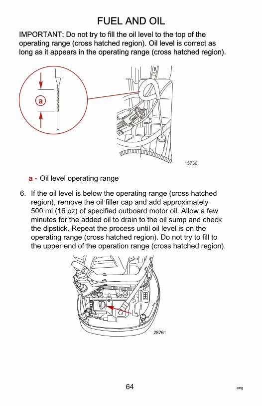
FUEL AND OIL
64 eng
IMPORTANT: Do not try to fill the oil level to the top of theoperating range (cross hatched region). Oil level is correct aslong as it appears in the operating range (cross hatched region).
a - Oil level operating range
6. If the oil level is below the operating range (cross hatchedregion), remove the oil filler cap and add approximately500 ml (16 oz) of specified outboard motor oil. Allow a fewminutes for the added oil to drain to the oil sump and checkthe dipstick. Repeat the process until oil level is on theoperating range (cross hatched region). Do not try to fill tothe upper end of the operation range (cross hatched region).
28761
a
15730

FUEL AND OIL
eng 65
IMPORTANT: Inspect oil for signs of contamination. Oilcontaminated with water will have a milky color to it; oilcontaminated with fuel will have a strong fuel smell. Ifcontaminated oil is noticed, have the engine checked by yourdealer.7. Push the dipstick back in all the way.8. Install the oil fill cap hand tight.9. Install the top cowl.
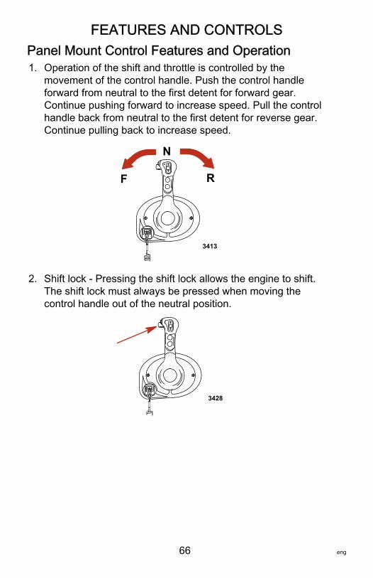
FEATURES AND CONTROLS
66 eng
Panel Mount Control Features and Operation1. Operation of the shift and throttle is controlled by the
movement of the control handle. Push the control handleforward from neutral to the first detent for forward gear.Continue pushing forward to increase speed. Pull the controlhandle back from neutral to the first detent for reverse gear.Continue pulling back to increase speed.
F
N
R
3413
2. Shift lock ‑ Pressing the shift lock allows the engine to shift.The shift lock must always be pressed when moving thecontrol handle out of the neutral position.
3428
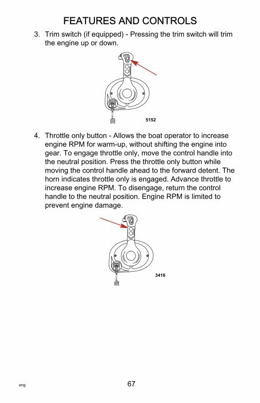
FEATURES AND CONTROLS
eng 67
3. Trim switch (if equipped) ‑ Pressing the trim switch will trimthe engine up or down.
5152
4. Throttle only button ‑ Allows the boat operator to increaseengine RPM for warm‑up, without shifting the engine intogear. To engage throttle only, move the control handle intothe neutral position. Press the throttle only button whilemoving the control handle ahead to the forward detent. Thehorn indicates throttle only is engaged. Advance throttle toincrease engine RPM. To disengage, return the controlhandle to the neutral position. Engine RPM is limited toprevent engine damage.
3416
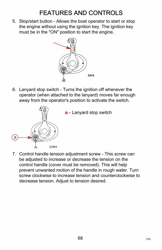
FEATURES AND CONTROLS
68 eng
5. Stop/start button ‑ Allows the boat operator to start or stopthe engine without using the ignition key. The ignition keymust be in the "ON" position to start the engine.
3414
6. Lanyard stop switch ‑ Turns the ignition off whenever theoperator (when attached to the lanyard) moves far enoughaway from the operator's position to activate the switch.
a - Lanyard stop switch
7. Control handle tension adjustment screw ‑ This screw canbe adjusted to increase or decrease the tension on thecontrol handle (cover must be removed). This will helpprevent unwanted motion of the handle in rough water. Turnscrew clockwise to increase tension and counterclockwise todecrease tension. Adjust to tension desired.
a
22964
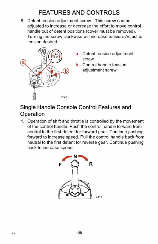
FEATURES AND CONTROLS
eng 69
8. Detent tension adjustment screw ‑ This screw can beadjusted to increase or decrease the effort to move controlhandle out of detent positions (cover must be removed).Turning the screw clockwise will increase tension. Adjust totension desired.
a - Detent tension adjustmentscrew
b - Control handle tensionadjustment screw
Single Handle Console Control Features andOperation1. Operation of shift and throttle is controlled by the movement
of the control handle. Push the control handle forward fromneutral to the first detent for forward gear. Continue pushingforward to increase speed. Pull the control handle back fromneutral to the first detent for reverse gear. Continue pushingback to increase speed.
FN
R
3417
5171
+-a
b
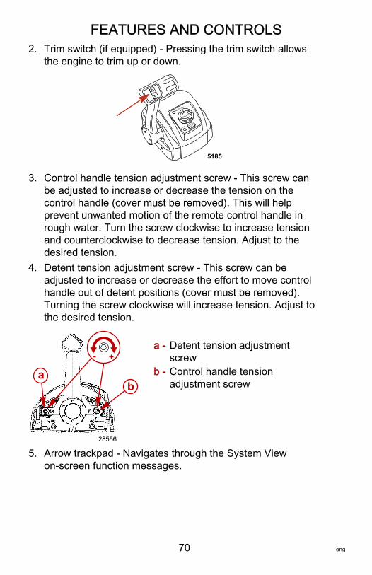
FEATURES AND CONTROLS
70 eng
2. Trim switch (if equipped) ‑ Pressing the trim switch allowsthe engine to trim up or down.
5185
3. Control handle tension adjustment screw ‑ This screw canbe adjusted to increase or decrease the tension on thecontrol handle (cover must be removed). This will helpprevent unwanted motion of the remote control handle inrough water. Turn the screw clockwise to increase tensionand counterclockwise to decrease tension. Adjust to thedesired tension.
4. Detent tension adjustment screw ‑ This screw can beadjusted to increase or decrease the effort to move controlhandle out of detent positions (cover must be removed).Turning the screw clockwise will increase tension. Adjust tothe desired tension.
a - Detent tension adjustmentscrew
b - Control handle tensionadjustment screw
5. Arrow trackpad ‑ Navigates through the System Viewon‑screen function messages.
ab
28556
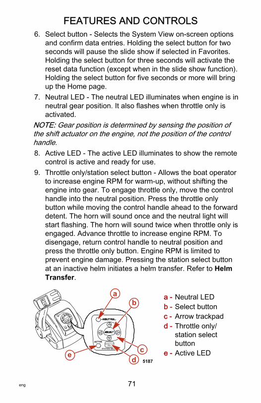
FEATURES AND CONTROLS
eng 71
6. Select button ‑ Selects the System View on‑screen optionsand confirm data entries. Holding the select button for twoseconds will pause the slide show if selected in Favorites.Holding the select button for three seconds will activate thereset data function (except when in the slide show function).Holding the select button for five seconds or more will bringup the Home page.
7. Neutral LED ‑ The neutral LED illuminates when engine is inneutral gear position. It also flashes when throttle only isactivated.
NOTE: Gear position is determined by sensing the position ofthe shift actuator on the engine, not the position of the controlhandle.8. Active LED ‑ The active LED illuminates to show the remote
control is active and ready for use.9. Throttle only/station select button ‑ Allows the boat operator
to increase engine RPM for warm‑up, without shifting theengine into gear. To engage throttle only, move the controlhandle into the neutral position. Press the throttle onlybutton while moving the control handle ahead to the forwarddetent. The horn will sound once and the neutral light willstart flashing. The horn will sound twice when throttle only isengaged. Advance throttle to increase engine RPM. Todisengage, return control handle to neutral position andpress the throttle only button. Engine RPM is limited toprevent engine damage. Pressing the station select buttonat an inactive helm initiates a helm transfer. Refer to HelmTransfer.
a - Neutral LEDb - Select buttonc - Arrow trackpadd - Throttle only/
station selectbutton
e - Active LEDd
ba
ce5187
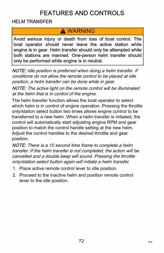
FEATURES AND CONTROLS
72 eng
HELM TRANSFER
! WARNINGAvoid serious injury or death from loss of boat control. Theboat operator should never leave the active station whileengine is in gear. Helm transfer should only be attempted whileboth stations are manned. One‑person helm transfer shouldonly be performed while engine is in neutral.
NOTE: Idle position is preferred when doing a helm transfer. Ifconditions do not allow the remote control to be placed at idleposition, a helm transfer can be done while in gear.NOTE: The active light on the remote control will be illuminatedat the helm that is in control of the engine.The helm transfer function allows the boat operator to selectwhich helm is in control of engine operation. Pressing the throttleonly/station select button two times allows engine control to betransferred to a new helm. When a helm transfer is initiated, thecontrol will automatically start adjusting engine RPM and gearposition to match the control handle setting at the new helm.Adjust the control handles to the desired throttle and gearposition.NOTE: There is a 10 second time frame to complete a helmtransfer. If the helm transfer is not completed, the action will becancelled and a double beep will sound. Pressing the throttleonly/station select button again will initiate a helm transfer.1. Place active remote control lever to idle position.2. Proceed to the inactive helm and position remote control
lever to the idle position.
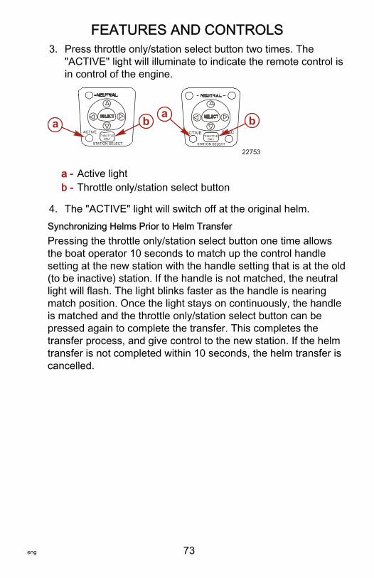
FEATURES AND CONTROLS
eng 73
3. Press throttle only/station select button two times. The"ACTIVE" light will illuminate to indicate the remote control isin control of the engine.
a - Active lightb - Throttle only/station select button
4. The "ACTIVE" light will switch off at the original helm.Synchronizing Helms Prior to Helm TransferPressing the throttle only/station select button one time allowsthe boat operator 10 seconds to match up the control handlesetting at the new station with the handle setting that is at the old(to be inactive) station. If the handle is not matched, the neutrallight will flash. The light blinks faster as the handle is nearingmatch position. Once the light stays on continuously, the handleis matched and the throttle only/station select button can bepressed again to complete the transfer. This completes thetransfer process, and give control to the new station. If the helmtransfer is not completed within 10 seconds, the helm transfer iscancelled.
ACTIVE
STATION SELECT
ACTIVE SYNC
STAT ION SELECT
THROTTLEONLY
THROTTLEONLY
22753
a ba b
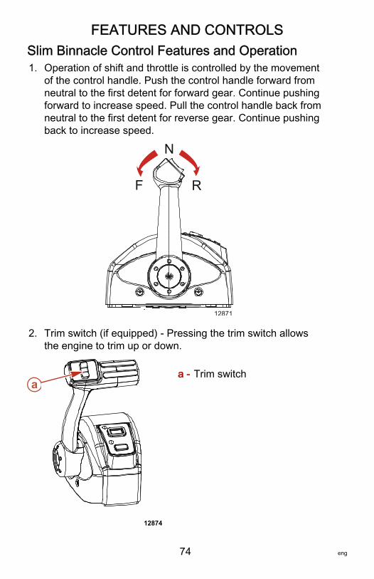
FEATURES AND CONTROLS
74 eng
Slim Binnacle Control Features and Operation1. Operation of shift and throttle is controlled by the movement
of the control handle. Push the control handle forward fromneutral to the first detent for forward gear. Continue pushingforward to increase speed. Pull the control handle back fromneutral to the first detent for reverse gear. Continue pushingback to increase speed.
F
N
R
12871
2. Trim switch (if equipped) ‑ Pressing the trim switch allowsthe engine to trim up or down.
a - Trim switch
12874
a
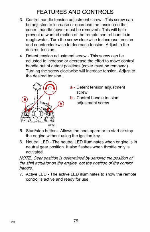
FEATURES AND CONTROLS
eng 75
3. Control handle tension adjustment screw ‑ This screw canbe adjusted to increase or decrease the tension on thecontrol handle (cover must be removed). This will helpprevent unwanted motion of the remote control handle inrough water. Turn the screw clockwise to increase tensionand counterclockwise to decrease tension. Adjust to thedesired tension.
4. Detent tension adjustment screw ‑ This screw can beadjusted to increase or decrease the effort to move controlhandle out of detent positions (cover must be removed).Turning the screw clockwise will increase tension. Adjust tothe desired tension.
a - Detent tension adjustmentscrew
b - Control handle tensionadjustment screw
5. Start/stop button ‑ Allows the boat operator to start or stopthe engine without using the ignition key.
6. Neutral LED ‑ The neutral LED illuminates when engine is inneutral gear position. It also flashes when throttle only isactivated.
NOTE: Gear position is determined by sensing the position ofthe shift actuator on the engine, not the position of the controlhandle.7. Active LED ‑ The active LED illuminates to show the remote
control is active and ready for use.
ab
28556
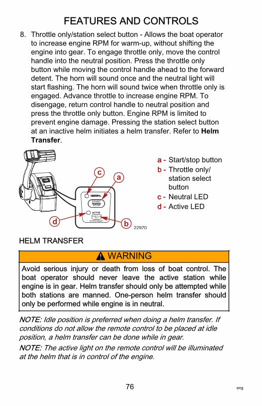
FEATURES AND CONTROLS
76 eng
8. Throttle only/station select button ‑ Allows the boat operatorto increase engine RPM for warm‑up, without shifting theengine into gear. To engage throttle only, move the controlhandle into the neutral position. Press the throttle onlybutton while moving the control handle ahead to the forwarddetent. The horn will sound once and the neutral light willstart flashing. The horn will sound twice when throttle only isengaged. Advance throttle to increase engine RPM. Todisengage, return control handle to neutral position andpress the throttle only button. Engine RPM is limited toprevent engine damage. Pressing the station select buttonat an inactive helm initiates a helm transfer. Refer to HelmTransfer.
a - Start/stop buttonb - Throttle only/
station selectbutton
c - Neutral LEDd - Active LED
HELM TRANSFER
! WARNINGAvoid serious injury or death from loss of boat control. Theboat operator should never leave the active station whileengine is in gear. Helm transfer should only be attempted whileboth stations are manned. One‑person helm transfer shouldonly be performed while engine is in neutral.
NOTE: Idle position is preferred when doing a helm transfer. Ifconditions do not allow the remote control to be placed at idleposition, a helm transfer can be done while in gear.NOTE: The active light on the remote control will be illuminatedat the helm that is in control of the engine.
STARTSTOP
22970d
c a
b
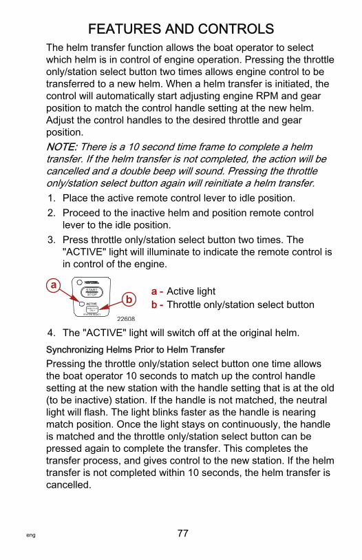
FEATURES AND CONTROLS
eng 77
The helm transfer function allows the boat operator to selectwhich helm is in control of engine operation. Pressing the throttleonly/station select button two times allows engine control to betransferred to a new helm. When a helm transfer is initiated, thecontrol will automatically start adjusting engine RPM and gearposition to match the control handle setting at the new helm.Adjust the control handles to the desired throttle and gearposition.NOTE: There is a 10 second time frame to complete a helmtransfer. If the helm transfer is not completed, the action will becancelled and a double beep will sound. Pressing the throttleonly/station select button again will reinitiate a helm transfer.1. Place the active remote control lever to idle position.2. Proceed to the inactive helm and position remote control
lever to the idle position.3. Press throttle only/station select button two times. The
"ACTIVE" light will illuminate to indicate the remote control isin control of the engine.
a - Active lightb - Throttle only/station select button
4. The "ACTIVE" light will switch off at the original helm.Synchronizing Helms Prior to Helm TransferPressing the throttle only/station select button one time allowsthe boat operator 10 seconds to match up the control handlesetting at the new station with the handle setting that is at the old(to be inactive) station. If the handle is not matched, the neutrallight will flash. The light blinks faster as the handle is nearingmatch position. Once the light stays on continuously, the handleis matched and the throttle only/station select button can bepressed again to complete the transfer. This completes thetransfer process, and gives control to the new station. If the helmtransfer is not completed within 10 seconds, the helm transfer iscancelled.
STARTSTOP
22608
ab
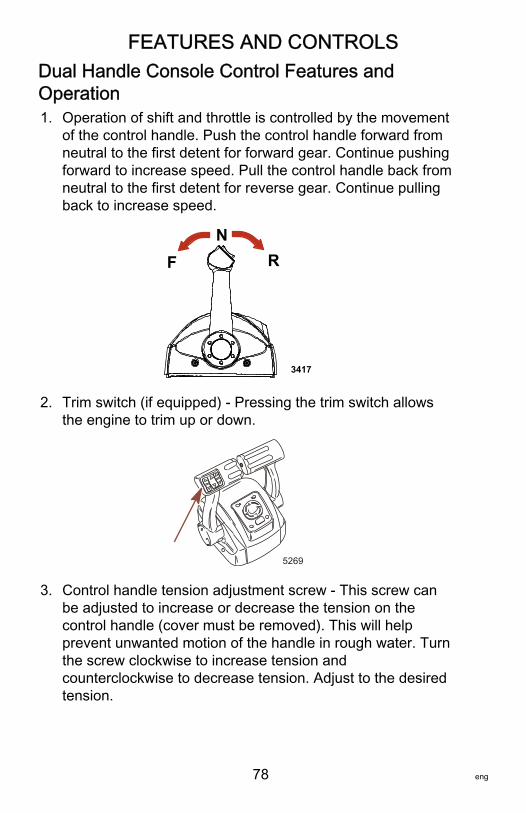
FEATURES AND CONTROLS
78 eng
Dual Handle Console Control Features andOperation1. Operation of shift and throttle is controlled by the movement
of the control handle. Push the control handle forward fromneutral to the first detent for forward gear. Continue pushingforward to increase speed. Pull the control handle back fromneutral to the first detent for reverse gear. Continue pullingback to increase speed.
FN
R
3417
2. Trim switch (if equipped) ‑ Pressing the trim switch allowsthe engine to trim up or down.
5269
3. Control handle tension adjustment screw ‑ This screw canbe adjusted to increase or decrease the tension on thecontrol handle (cover must be removed). This will helpprevent unwanted motion of the handle in rough water. Turnthe screw clockwise to increase tension andcounterclockwise to decrease tension. Adjust to the desiredtension.
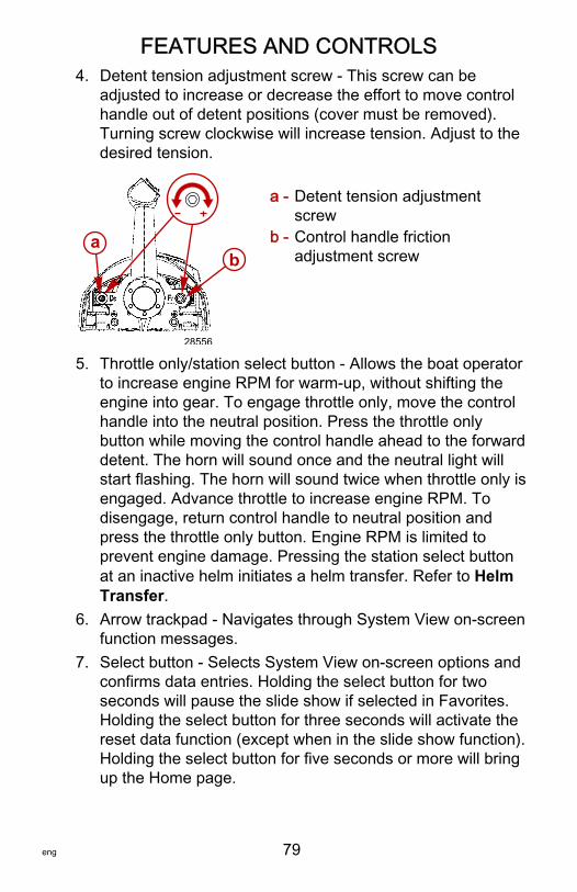
FEATURES AND CONTROLS
eng 79
4. Detent tension adjustment screw ‑ This screw can beadjusted to increase or decrease the effort to move controlhandle out of detent positions (cover must be removed).Turning screw clockwise will increase tension. Adjust to thedesired tension.
a - Detent tension adjustmentscrew
b - Control handle frictionadjustment screw
5. Throttle only/station select button ‑ Allows the boat operatorto increase engine RPM for warm‑up, without shifting theengine into gear. To engage throttle only, move the controlhandle into the neutral position. Press the throttle onlybutton while moving the control handle ahead to the forwarddetent. The horn will sound once and the neutral light willstart flashing. The horn will sound twice when throttle only isengaged. Advance throttle to increase engine RPM. Todisengage, return control handle to neutral position andpress the throttle only button. Engine RPM is limited toprevent engine damage. Pressing the station select buttonat an inactive helm initiates a helm transfer. Refer to HelmTransfer.
6. Arrow trackpad ‑ Navigates through System View on‑screenfunction messages.
7. Select button ‑ Selects System View on‑screen options andconfirms data entries. Holding the select button for twoseconds will pause the slide show if selected in Favorites.Holding the select button for three seconds will activate thereset data function (except when in the slide show function).Holding the select button for five seconds or more will bringup the Home page.
ab
28556
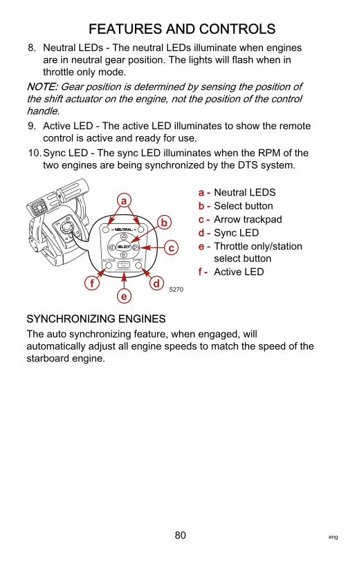
FEATURES AND CONTROLS
80 eng
8. Neutral LEDs ‑ The neutral LEDs illuminate when enginesare in neutral gear position. The lights will flash when inthrottle only mode.
NOTE: Gear position is determined by sensing the position ofthe shift actuator on the engine, not the position of the controlhandle.9. Active LED ‑ The active LED illuminates to show the remote
control is active and ready for use.10.Sync LED ‑ The sync LED illuminates when the RPM of the
two engines are being synchronized by the DTS system.
a - Neutral LEDSb - Select buttonc - Arrow trackpadd - Sync LEDe - Throttle only/station
select buttonf - Active LED
SYNCHRONIZING ENGINESThe auto synchronizing feature, when engaged, willautomatically adjust all engine speeds to match the speed of thestarboard engine.
5270
ACTIVE SYNCTHROTTLE
ONLY
STATION SELECT
a
b
c
de
f
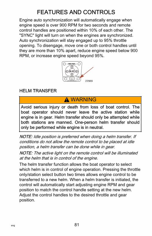
FEATURES AND CONTROLS
eng 81
Engine auto synchronization will automatically engage whenengine speed is over 900 RPM for two seconds and remotecontrol handles are positioned within 10% of each other. The"SYNC" light will turn on when the engines are synchronized.Auto synchronization will stay engaged up to 95% throttleopening. To disengage, move one or both control handles untilthey are more than 10% apart, reduce engine speed below 900RPM, or increase engine speed beyond 95%.
22969
ACTIVE SYNC
STAT ION SELECT
THROTTLEONLY
HELM TRANSFER
! WARNINGAvoid serious injury or death from loss of boat control. Theboat operator should never leave the active station whileengine is in gear. Helm transfer should only be attempted whileboth stations are manned. One‑person helm transfer shouldonly be performed while engine is in neutral.
NOTE: Idle position is preferred when doing a helm transfer. Ifconditions do not allow the remote control to be placed at idleposition, a helm transfer can be done while in gear.NOTE: The active light on the remote control will be illuminatedat the helm that is in control of the engine.The helm transfer function allows the boat operator to selectwhich helm is in control of engine operation. Pressing the throttleonly/station select button two times allows engine control to betransferred to a new helm. When a helm transfer is initiated, thecontrol will automatically start adjusting engine RPM and gearposition to match the control handle setting at the new helm.Adjust the control handles to the desired throttle and gearposition.
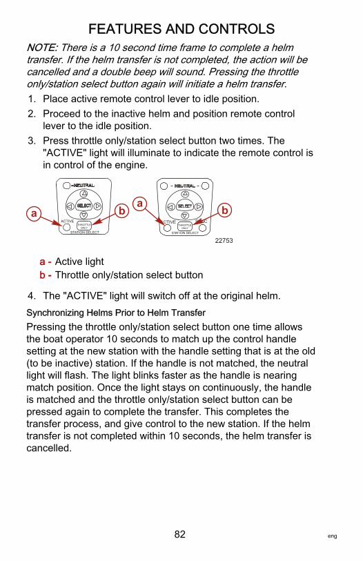
FEATURES AND CONTROLS
82 eng
NOTE: There is a 10 second time frame to complete a helmtransfer. If the helm transfer is not completed, the action will becancelled and a double beep will sound. Pressing the throttleonly/station select button again will initiate a helm transfer.1. Place active remote control lever to idle position.2. Proceed to the inactive helm and position remote control
lever to the idle position.3. Press throttle only/station select button two times. The
"ACTIVE" light will illuminate to indicate the remote control isin control of the engine.
a - Active lightb - Throttle only/station select button
4. The "ACTIVE" light will switch off at the original helm.Synchronizing Helms Prior to Helm TransferPressing the throttle only/station select button one time allowsthe boat operator 10 seconds to match up the control handlesetting at the new station with the handle setting that is at the old(to be inactive) station. If the handle is not matched, the neutrallight will flash. The light blinks faster as the handle is nearingmatch position. Once the light stays on continuously, the handleis matched and the throttle only/station select button can bepressed again to complete the transfer. This completes thetransfer process, and give control to the new station. If the helmtransfer is not completed within 10 seconds, the helm transfer iscancelled.
ACTIVE
STATION SELECT
ACTIVE SYNC
STAT ION SELECT
THROTTLEONLY
THROTTLEONLY
22753
a ba b
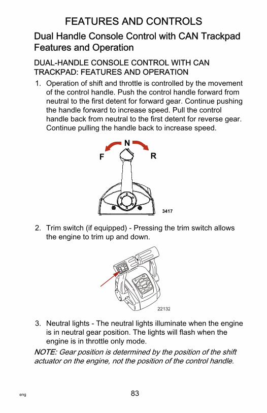
FEATURES AND CONTROLS
eng 83
Dual Handle Console Control with CAN TrackpadFeatures and OperationDUAL-HANDLE CONSOLE CONTROL WITH CANTRACKPAD: FEATURES AND OPERATION1. Operation of shift and throttle is controlled by the movement
of the control handle. Push the control handle forward fromneutral to the first detent for forward gear. Continue pushingthe handle forward to increase speed. Pull the controlhandle back from neutral to the first detent for reverse gear.Continue pulling the handle back to increase speed.
FN
R
3417
2. Trim switch (if equipped) ‑ Pressing the trim switch allowsthe engine to trim up and down.
N E U T R A L
SYNC
THROTTLE
ONLY
+
-TROLL
TRANSFER
DOCK
1 LEVER
22132
3. Neutral lights ‑ The neutral lights illuminate when the engineis in neutral gear position. The lights will flash when theengine is in throttle only mode.
NOTE: Gear position is determined by the position of the shiftactuator on the engine, not the position of the control handle.
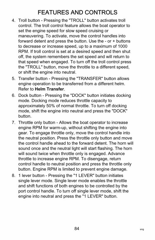
FEATURES AND CONTROLS
84 eng
4. Troll button ‑ Pressing the "TROLL" button activates trollcontrol. The troll control feature allows the boat operator toset the engine speed for slow speed cruising ormaneuvering. To activate, move the control handles intoforward detent and press the button. Use the ‑ or + buttonsto decrease or increase speed, up to a maximum of 1000RPM. If troll control is set at a desired speed and then shutoff, the system remembers the set speed and will return tothat speed when engaged. To turn off the troll control pressthe "TROLL" button, move the throttle to a different speed,or shift the engine into neutral.
5. Transfer button ‑ Pressing the "TRANSFER" button allowsengine operation to be transferred from a different helm.Refer to Helm Transfer.
6. Dock button ‑ Pressing the "DOCK" button initiates dockingmode. Docking mode reduces throttle capacity toapproximately 50% of normal throttle. To turn off dockingmode, shift the engine into neutral and press the "DOCK"button.
7. Throttle only button ‑ Allows the boat operator to increaseengine RPM for warm‑up, without shifting the engine intogear. To engage throttle only, move the control handle intothe neutral position. Press the throttle only button and movethe control handle ahead to the forward detent. The horn willsound once and the neutral light will start flashing. The hornwill sound twice when throttle only is engaged. Advancethrottle to increase engine RPM. To disengage, returncontrol handle to neutral position and press the throttle onlybutton. Engine RPM is limited to prevent engine damage.
8. 1 lever button ‑ Pressing the "1 LEVER" button initiatessingle lever mode. Single lever mode enables the throttleand shift functions of both engines to be controlled by theport control handle. To turn off single lever mode, shift theengine into neutral and press the "1 LEVER" button.
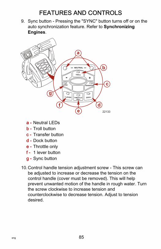
FEATURES AND CONTROLS
eng 85
9. Sync button ‑ Pressing the "SYNC" button turns off or on theauto synchronization feature. Refer to SynchronizingEngines.
a - Neutral LEDsb - Troll buttonc - Transfer buttond - Dock buttone - Throttle onlyf - 1 lever buttong - Sync button
10.Control handle tension adjustment screw ‑ This screw canbe adjusted to increase or decrease the tension on thecontrol handle (cover must be removed). This will helpprevent unwanted motion of the handle in rough water. Turnthe screw clockwise to increase tension andcounterclockwise to decrease tension. Adjust to tensiondesired.
N E U T R A L
22133
SYNC
1 LEVER
NEUTRAL
TROLL
THROTTLE ONLY
DOCK
TRANSFER
+-
a
b
c
e
g
f d
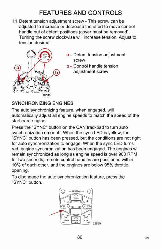
FEATURES AND CONTROLS
86 eng
11.Detent tension adjustment screw ‑ This screw can beadjusted to increase or decrease the effort to move controlhandle out of detent positions (cover must be removed).Turning the screw clockwise will increase tension. Adjust totension desired.
a - Detent tension adjustmentscrew
b - Control handle tensionadjustment screw
SYNCHRONIZING ENGINESThe auto synchronizing feature, when engaged, willautomatically adjust all engine speeds to match the speed of thestarboard engine.Press the "SYNC" button on the CAN trackpad to turn autosynchronization on or off. When the sync LED is yellow, the"SYNC" button has been pressed, but the conditions are not rightfor auto synchronization to engage. When the sync LED turnsred, engine synchronization has been engaged. The engines willremain synchronized as long as engine speed is over 900 RPMfor two seconds, remote control handles are positioned within10% of each other, and the engines are below 95% throttleopening.To disengage the auto synchronization feature, press the"SYNC" button.
SYNC
1 LEVER
NEUTRAL
TROLL
THROTTLE ONLY
DOCK
TRANSFER
+-
22590
ab
28556
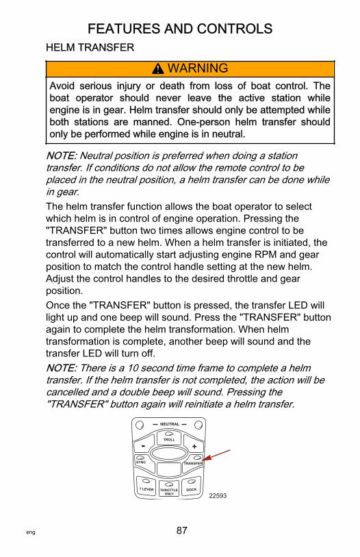
FEATURES AND CONTROLS
eng 87
HELM TRANSFER
! WARNINGAvoid serious injury or death from loss of boat control. Theboat operator should never leave the active station whileengine is in gear. Helm transfer should only be attempted whileboth stations are manned. One‑person helm transfer shouldonly be performed while engine is in neutral.
NOTE: Neutral position is preferred when doing a stationtransfer. If conditions do not allow the remote control to beplaced in the neutral position, a helm transfer can be done whilein gear.The helm transfer function allows the boat operator to selectwhich helm is in control of engine operation. Pressing the"TRANSFER" button two times allows engine control to betransferred to a new helm. When a helm transfer is initiated, thecontrol will automatically start adjusting engine RPM and gearposition to match the control handle setting at the new helm.Adjust the control handles to the desired throttle and gearposition.Once the "TRANSFER" button is pressed, the transfer LED willlight up and one beep will sound. Press the "TRANSFER" buttonagain to complete the helm transformation. When helmtransformation is complete, another beep will sound and thetransfer LED will turn off.NOTE: There is a 10 second time frame to complete a helmtransfer. If the helm transfer is not completed, the action will becancelled and a double beep will sound. Pressing the"TRANSFER" button again will reinitiate a helm transfer.
SYNC
1 LEVER
NEUTRAL
TROLL
THROTTLE ONLY
DOCK
TRANSFER
+-
22593
FEATURES AND CONTROLS
88 eng
Synchronizing Helms Prior to TransferPressing the "TRANSFER" button allows the boat operator 10seconds to match up the control handle settings at the new helmwith the handle settings that are at the old (to be inactive) helm.If the handles are not matched, the neutral lights will flash. Thelight blinks faster as the handles are nearing match position.Once the light stays on continuously, the handles are matchedand the button can be pressed again to complete the transfer.This completes the transfer process, and gives control to thenew station. If the helm transfer is not completed within 10seconds, the action will be cancelled.
Shadow Mode Control Features and OperationTRIPLE ENGINE THROTTLE AND SHIFT OPERATIONMovement of the handles on the remote control allows the boatoperator to control the engine throttle speed and gear shiftpositions of all three engines.The throttle and shift function is dependant on what engines arerunning. Refer to the following table.
Port Engine CenterEngine
StarboardEngine Control Handle Function
Running Running Running
Port engine throttle and shift =controlled by port control handle
Starboard engine throttle and shift= controlled by starboard controlhandle
Center engine throttle = average ofport and starboard engines
Center engine shift = neutralunless both engines are in thesame gear
Running Running OffPort and center engine throttle andshift = controlled by port controlhandle
Off Running RunningStarboard and center enginethrottle and shift = controlled bystarboard control handle
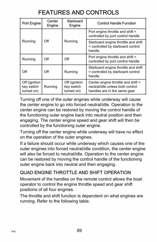
FEATURES AND CONTROLS
eng 89
Port Engine CenterEngine
StarboardEngine Control Handle Function
Running Off Running
Port engine throttle and shift =controlled by port control handle
Starboard engine throttle and shift= controlled by starboard controlhandle
Running Off Off Port engine throttle and shift =controlled by port control handle
Off Off RunningStarboard engine throttle and shift= controlled by starboard controlhandle
Off (ignitionkey switchturned on)
RunningOff (ignitionkey switchturned on)
Center engine throttle and shift =neutral/idle unless both controlhandles are in the same gear
Turning off one of the outer engines while underway will causethe center engine to go into forced neutral/idle. Operation to thecenter engine can be restored by moving the control handle ofthe functioning outer engine back into neutral position and thenengaging. The center engine speed and gear shift will then becontrolled by the functioning outer engine.Turning off the center engine while underway will have no effecton the operation of the outer engines.If a failure should occur while underway which causes one of theouter engines into forced neutral/idle condition, the center enginewill also be forced to neutral/idle. Operation to the center enginecan be restored by moving the control handle of the functioningouter engine back into neutral and then engaging.
QUAD ENGINE THROTTLE AND SHIFT OPERATIONMovement of the handles on the remote control allows the boatoperator to control the engine throttle speed and gear shiftpositions of all four engines.The throttle and shift function is dependent on what engines arerunning. Refer to the following table.
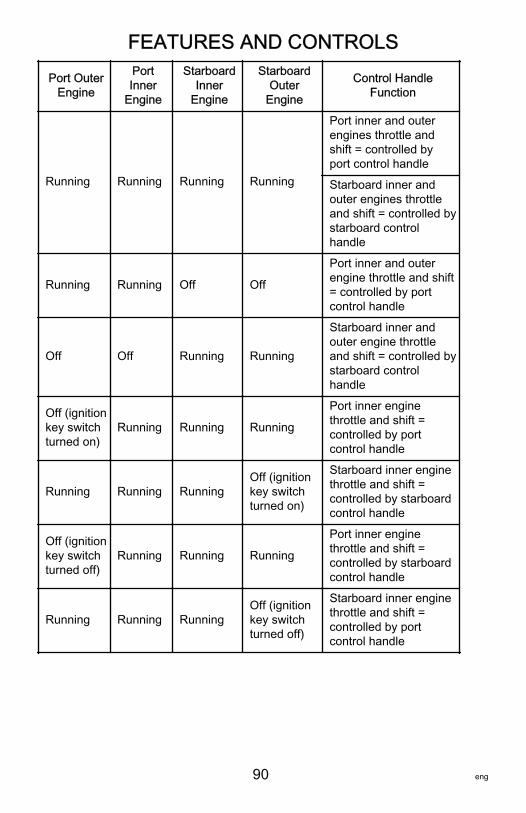
FEATURES AND CONTROLS
90 eng
Port OuterEngine
PortInner
Engine
StarboardInner
Engine
StarboardOuter
Engine
Control HandleFunction
Running Running Running Running
Port inner and outerengines throttle andshift = controlled byport control handle
Starboard inner andouter engines throttleand shift = controlled bystarboard controlhandle
Running Running Off Off
Port inner and outerengine throttle and shift= controlled by portcontrol handle
Off Off Running Running
Starboard inner andouter engine throttleand shift = controlled bystarboard controlhandle
Off (ignitionkey switchturned on)
Running Running Running
Port inner enginethrottle and shift =controlled by portcontrol handle
Running Running RunningOff (ignitionkey switchturned on)
Starboard inner enginethrottle and shift =controlled by starboardcontrol handle
Off (ignitionkey switchturned off)
Running Running Running
Port inner enginethrottle and shift =controlled by starboardcontrol handle
Running Running RunningOff (ignitionkey switchturned off)
Starboard inner enginethrottle and shift =controlled by portcontrol handle
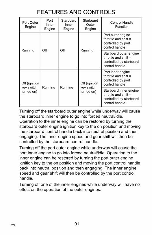
FEATURES AND CONTROLS
eng 91
Port OuterEngine
PortInner
Engine
StarboardInner
Engine
StarboardOuter
Engine
Control HandleFunction
Running Off Off Running
Port outer enginethrottle and shift =controlled by portcontrol handle
Starboard outer enginethrottle and shift =controlled by starboardcontrol handle
Off (ignitionkey switchturned on)
Running RunningOff (ignitionkey switchturned on)
Port inner enginethrottle and shift =controlled by portcontrol handle
Starboard inner enginethrottle and shift =controlled by starboardcontrol handle
Turning off the starboard outer engine while underway will causethe starboard inner engine to go into forced neutral/idle.Operation to the inner engine can be restored by turning thestarboard outer engine ignition key to the on position and movingthe starboard control handle back into neutral position and thenengaging. The inner engine speed and gear shift will then becontrolled by the starboard control handle.Turning off the port outer engine while underway will cause theport inner engine to go into forced neutral/idle. Operation to theinner engine can be restored by turning the port outer engineignition key to the on position and moving the port control handleback into neutral position and then engaging. The inner enginespeed and gear shift will then be controlled by the port controlhandle.Turning off one of the inner engines while underway will have noeffect on the operation of the outer engines.
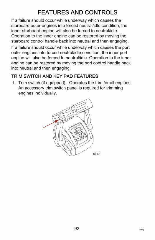
FEATURES AND CONTROLS
92 eng
If a failure should occur while underway which causes thestarboard outer engines into forced neutral/idle condition, theinner starboard engine will also be forced to neutral/idle.Operation to the inner engine can be restored by moving thestarboard control handle back into neutral and then engaging.If a failure should occur while underway which causes the portouter engines into forced neutral/idle condition, the inner portengine will also be forced to neutral/idle. Operation to the innerengine can be restored by moving the port control handle backinto neutral and then engaging.
TRIM SWITCH AND KEY PAD FEATURES1. Trim switch (if equipped) ‑ Operates the trim for all engines.
An accessory trim switch panel is required for trimmingengines individually.
B O T H
N E U T R A L
S E L E C T
A C T I V E O N L Y T H R O T T L E
S T A T I O N S E L E C T
S Y N C
13853
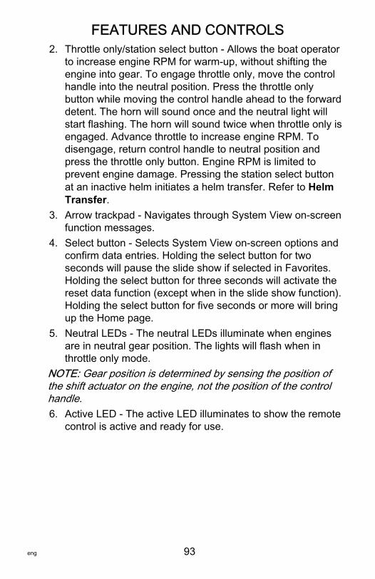
FEATURES AND CONTROLS
eng 93
2. Throttle only/station select button ‑ Allows the boat operatorto increase engine RPM for warm‑up, without shifting theengine into gear. To engage throttle only, move the controlhandle into the neutral position. Press the throttle onlybutton while moving the control handle ahead to the forwarddetent. The horn will sound once and the neutral light willstart flashing. The horn will sound twice when throttle only isengaged. Advance throttle to increase engine RPM. Todisengage, return control handle to neutral position andpress the throttle only button. Engine RPM is limited toprevent engine damage. Pressing the station select buttonat an inactive helm initiates a helm transfer. Refer to HelmTransfer.
3. Arrow trackpad ‑ Navigates through System View on‑screenfunction messages.
4. Select button ‑ Selects System View on‑screen options andconfirm data entries. Holding the select button for twoseconds will pause the slide show if selected in Favorites.Holding the select button for three seconds will activate thereset data function (except when in the slide show function).Holding the select button for five seconds or more will bringup the Home page.
5. Neutral LEDs ‑ The neutral LEDs illuminate when enginesare in neutral gear position. The lights will flash when inthrottle only mode.
NOTE: Gear position is determined by sensing the position ofthe shift actuator on the engine, not the position of the controlhandle.6. Active LED ‑ The active LED illuminates to show the remote
control is active and ready for use.
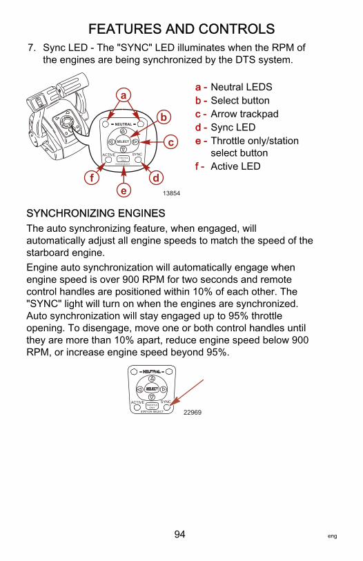
FEATURES AND CONTROLS
94 eng
7. Sync LED ‑ The "SYNC" LED illuminates when the RPM ofthe engines are being synchronized by the DTS system.
a - Neutral LEDSb - Select buttonc - Arrow trackpadd - Sync LEDe - Throttle only/station
select buttonf - Active LED
SYNCHRONIZING ENGINESThe auto synchronizing feature, when engaged, willautomatically adjust all engine speeds to match the speed of thestarboard engine.Engine auto synchronization will automatically engage whenengine speed is over 900 RPM for two seconds and remotecontrol handles are positioned within 10% of each other. The"SYNC" light will turn on when the engines are synchronized.Auto synchronization will stay engaged up to 95% throttleopening. To disengage, move one or both control handles untilthey are more than 10% apart, reduce engine speed below 900RPM, or increase engine speed beyond 95%.
22969
ACTIVE SYNC
STAT ION SELECT
THROTTLEONLY
ACTIVE SYNCTHROTTLE
ONLY
STATION SELECT
a
b
c
de
f
NEUTRAL
SELECT
13854
FEATURES AND CONTROLS
eng 95
HELM TRANSFER
! WARNINGAvoid serious injury or death from loss of boat control. Theboat operator should never leave the active station whileengine is in gear. Helm transfer should only be attempted whileboth stations are manned. One‑person helm transfer shouldonly be performed while engine is in neutral.
NOTE: Idle position is preferred when doing a helm transfer. Ifconditions do not allow the remote control to be placed at idleposition, a helm transfer can be done while in gear.NOTE: The active light on the remote control will be illuminatedat the helm that is in control of the engine.The helm transfer function allows the boat operator to selectwhich helm is in control of engine operation. Pressing the throttleonly/station select button two times allows engine control to betransferred to a new helm. When a helm transfer is initiated, thecontrol will automatically start adjusting engine RPM and gearposition to match the control handle setting at the new helm.Adjust the control handles to the desired throttle and gearposition.NOTE: There is a 10 second time frame to complete a helmtransfer. If the helm transfer is not completed, the action will becancelled and a double beep will sound. Pressing the throttleonly/station select button again will initiate a helm transfer.1. Place active remote control lever to idle position.2. Proceed to the inactive helm and position remote control
lever to the idle position.
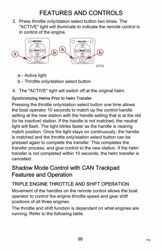
FEATURES AND CONTROLS
96 eng
3. Press throttle only/station select button two times. The"ACTIVE" light will illuminate to indicate the remote control isin control of the engine.
a - Active lightb - Throttle only/station select button
4. The "ACTIVE" light will switch off at the original helm.Synchronizing Helms Prior to Helm TransferPressing the throttle only/station select button one time allowsthe boat operator 10 seconds to match up the control handlesetting at the new station with the handle setting that is at the old(to be inactive) station. If the handle is not matched, the neutrallight will flash. The light blinks faster as the handle is nearingmatch position. Once the light stays on continuously, the handleis matched and the throttle only/station select button can bepressed again to complete the transfer. This completes thetransfer process, and give control to the new station. If the helmtransfer is not completed within 10 seconds, the helm transfer iscancelled.
Shadow Mode Control with CAN TrackpadFeatures and OperationTRIPLE ENGINE THROTTLE AND SHIFT OPERATIONMovement of the handles on the remote control allows the boatoperator to control the engine throttle speed and gear shiftpositions of all three engines.The throttle and shift function is dependant on what engines arerunning. Refer to the following table.
ACTIVE
STATION SELECT
ACTIVE SYNC
STAT ION SELECT
THROTTLEONLY
THROTTLEONLY
22753
a ba b
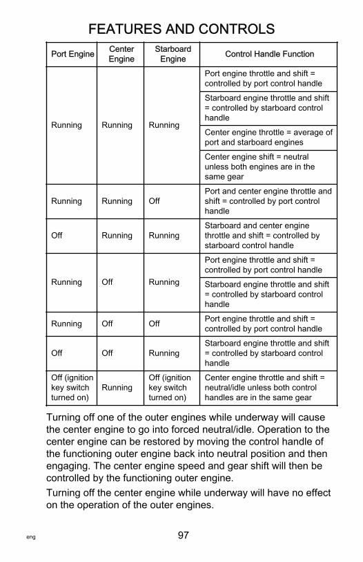
FEATURES AND CONTROLS
eng 97
Port Engine CenterEngine
StarboardEngine Control Handle Function
Running Running Running
Port engine throttle and shift =controlled by port control handle
Starboard engine throttle and shift= controlled by starboard controlhandle
Center engine throttle = average ofport and starboard engines
Center engine shift = neutralunless both engines are in thesame gear
Running Running OffPort and center engine throttle andshift = controlled by port controlhandle
Off Running RunningStarboard and center enginethrottle and shift = controlled bystarboard control handle
Running Off Running
Port engine throttle and shift =controlled by port control handle
Starboard engine throttle and shift= controlled by starboard controlhandle
Running Off Off Port engine throttle and shift =controlled by port control handle
Off Off RunningStarboard engine throttle and shift= controlled by starboard controlhandle
Off (ignitionkey switchturned on)
RunningOff (ignitionkey switchturned on)
Center engine throttle and shift =neutral/idle unless both controlhandles are in the same gear
Turning off one of the outer engines while underway will causethe center engine to go into forced neutral/idle. Operation to thecenter engine can be restored by moving the control handle ofthe functioning outer engine back into neutral position and thenengaging. The center engine speed and gear shift will then becontrolled by the functioning outer engine.Turning off the center engine while underway will have no effecton the operation of the outer engines.
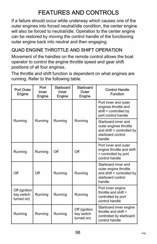
FEATURES AND CONTROLS
98 eng
If a failure should occur while underway which causes one of theouter engines into forced neutral/idle condition, the center enginewill also be forced to neutral/idle. Operation to the center enginecan be restored by moving the control handle of the functioningouter engine back into neutral and then engaging.
QUAD ENGINE THROTTLE AND SHIFT OPERATIONMovement of the handles on the remote control allows the boatoperator to control the engine throttle speed and gear shiftpositions of all four engines.The throttle and shift function is dependent on what engines arerunning. Refer to the following table.
Port OuterEngine
PortInner
Engine
StarboardInner
Engine
StarboardOuter
Engine
Control HandleFunction
Running Running Running Running
Port inner and outerengines throttle andshift = controlled byport control handle
Starboard inner andouter engines throttleand shift = controlled bystarboard controlhandle
Running Running Off Off
Port inner and outerengine throttle and shift= controlled by portcontrol handle
Off Off Running Running
Starboard inner andouter engine throttleand shift = controlled bystarboard controlhandle
Off (ignitionkey switchturned on)
Running Running Running
Port inner enginethrottle and shift =controlled by portcontrol handle
Running Running RunningOff (ignitionkey switchturned on)
Starboard inner enginethrottle and shift =controlled by starboardcontrol handle
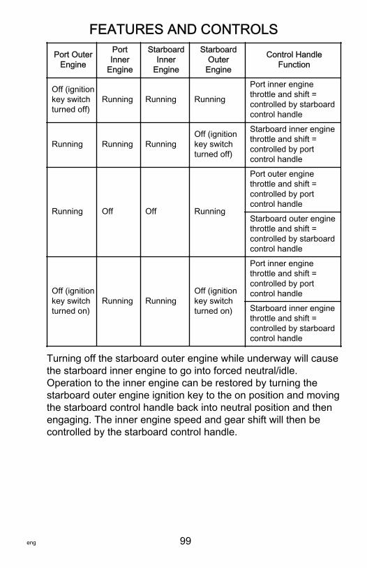
FEATURES AND CONTROLS
eng 99
Port OuterEngine
PortInner
Engine
StarboardInner
Engine
StarboardOuter
Engine
Control HandleFunction
Off (ignitionkey switchturned off)
Running Running Running
Port inner enginethrottle and shift =controlled by starboardcontrol handle
Running Running RunningOff (ignitionkey switchturned off)
Starboard inner enginethrottle and shift =controlled by portcontrol handle
Running Off Off Running
Port outer enginethrottle and shift =controlled by portcontrol handle
Starboard outer enginethrottle and shift =controlled by starboardcontrol handle
Off (ignitionkey switchturned on)
Running RunningOff (ignitionkey switchturned on)
Port inner enginethrottle and shift =controlled by portcontrol handle
Starboard inner enginethrottle and shift =controlled by starboardcontrol handle
Turning off the starboard outer engine while underway will causethe starboard inner engine to go into forced neutral/idle.Operation to the inner engine can be restored by turning thestarboard outer engine ignition key to the on position and movingthe starboard control handle back into neutral position and thenengaging. The inner engine speed and gear shift will then becontrolled by the starboard control handle.
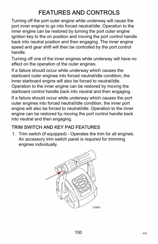
FEATURES AND CONTROLS
100 eng
Turning off the port outer engine while underway will cause theport inner engine to go into forced neutral/idle. Operation to theinner engine can be restored by turning the port outer engineignition key to the on position and moving the port control handleback into neutral position and then engaging. The inner enginespeed and gear shift will then be controlled by the port controlhandle.Turning off one of the inner engines while underway will have noeffect on the operation of the outer engines.If a failure should occur while underway which causes thestarboard outer engines into forced neutral/idle condition, theinner starboard engine will also be forced to neutral/idle.Operation to the inner engine can be restored by moving thestarboard control handle back into neutral and then engaging.If a failure should occur while underway which causes the portouter engines into forced neutral/idle condition, the inner portengine will also be forced to neutral/idle. Operation to the innerengine can be restored by moving the port control handle backinto neutral and then engaging.
TRIM SWITCH AND KEY PAD FEATURES1. Trim switch (if equipped) ‑ Operates the trim for all engines.
An accessory trim switch panel is required for trimmingengines individually.
22943
TRANSFER
DOCK
THROTTLE
ONLY
I LEVER
ALL
SYNC
TROLLNEUTRAL
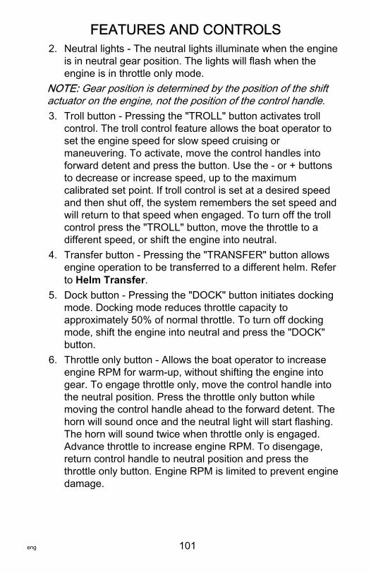
FEATURES AND CONTROLS
eng 101
2. Neutral lights ‑ The neutral lights illuminate when the engineis in neutral gear position. The lights will flash when theengine is in throttle only mode.
NOTE: Gear position is determined by the position of the shiftactuator on the engine, not the position of the control handle.3. Troll button ‑ Pressing the "TROLL" button activates troll
control. The troll control feature allows the boat operator toset the engine speed for slow speed cruising ormaneuvering. To activate, move the control handles intoforward detent and press the button. Use the ‑ or + buttonsto decrease or increase speed, up to the maximumcalibrated set point. If troll control is set at a desired speedand then shut off, the system remembers the set speed andwill return to that speed when engaged. To turn off the trollcontrol press the "TROLL" button, move the throttle to adifferent speed, or shift the engine into neutral.
4. Transfer button ‑ Pressing the "TRANSFER" button allowsengine operation to be transferred to a different helm. Referto Helm Transfer.
5. Dock button ‑ Pressing the "DOCK" button initiates dockingmode. Docking mode reduces throttle capacity toapproximately 50% of normal throttle. To turn off dockingmode, shift the engine into neutral and press the "DOCK"button.
6. Throttle only button ‑ Allows the boat operator to increaseengine RPM for warm‑up, without shifting the engine intogear. To engage throttle only, move the control handle intothe neutral position. Press the throttle only button whilemoving the control handle ahead to the forward detent. Thehorn will sound once and the neutral light will start flashing.The horn will sound twice when throttle only is engaged.Advance throttle to increase engine RPM. To disengage,return control handle to neutral position and press thethrottle only button. Engine RPM is limited to prevent enginedamage.
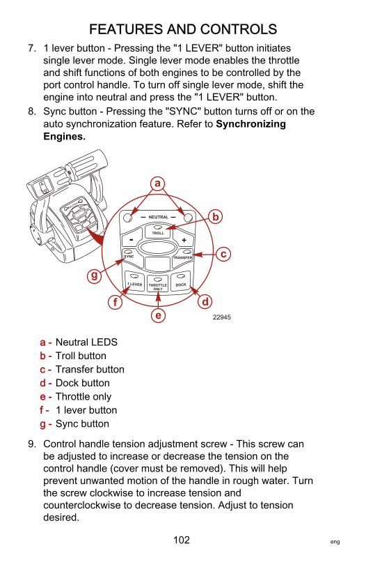
FEATURES AND CONTROLS
102 eng
7. 1 lever button ‑ Pressing the "1 LEVER" button initiatessingle lever mode. Single lever mode enables the throttleand shift functions of both engines to be controlled by theport control handle. To turn off single lever mode, shift theengine into neutral and press the "1 LEVER" button.
8. Sync button ‑ Pressing the "SYNC" button turns off or on theauto synchronization feature. Refer to SynchronizingEngines.
a - Neutral LEDSb - Troll buttonc - Transfer buttond - Dock buttone - Throttle onlyf - 1 lever buttong - Sync button
9. Control handle tension adjustment screw ‑ This screw canbe adjusted to increase or decrease the tension on thecontrol handle (cover must be removed). This will helpprevent unwanted motion of the handle in rough water. Turnthe screw clockwise to increase tension andcounterclockwise to decrease tension. Adjust to tensiondesired.
N E U T R A L
22945
SYNC
1 LEVER
NEUTRAL
TROLL
THROTTLE ONLY
DOCK
TRANSFER
+-
a
b
c
e
g
f d
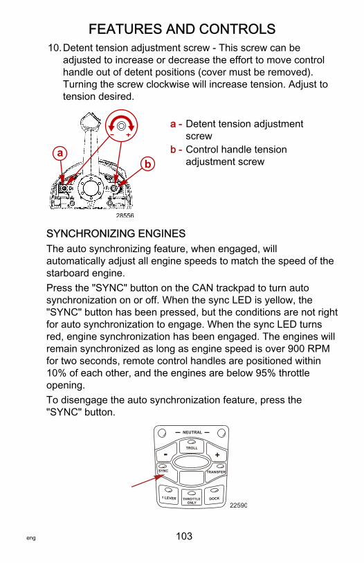
FEATURES AND CONTROLS
eng 103
10.Detent tension adjustment screw ‑ This screw can beadjusted to increase or decrease the effort to move controlhandle out of detent positions (cover must be removed).Turning the screw clockwise will increase tension. Adjust totension desired.
a - Detent tension adjustmentscrew
b - Control handle tensionadjustment screw
SYNCHRONIZING ENGINESThe auto synchronizing feature, when engaged, willautomatically adjust all engine speeds to match the speed of thestarboard engine.Press the "SYNC" button on the CAN trackpad to turn autosynchronization on or off. When the sync LED is yellow, the"SYNC" button has been pressed, but the conditions are not rightfor auto synchronization to engage. When the sync LED turnsred, engine synchronization has been engaged. The engines willremain synchronized as long as engine speed is over 900 RPMfor two seconds, remote control handles are positioned within10% of each other, and the engines are below 95% throttleopening.To disengage the auto synchronization feature, press the"SYNC" button.
SYNC
1 LEVER
NEUTRAL
TROLL
THROTTLE ONLY
DOCK
TRANSFER
+-
22590
ab
28556
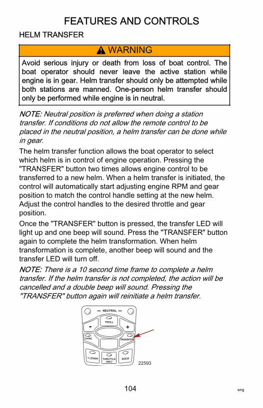
FEATURES AND CONTROLS
104 eng
HELM TRANSFER
! WARNINGAvoid serious injury or death from loss of boat control. Theboat operator should never leave the active station whileengine is in gear. Helm transfer should only be attempted whileboth stations are manned. One‑person helm transfer shouldonly be performed while engine is in neutral.
NOTE: Neutral position is preferred when doing a stationtransfer. If conditions do not allow the remote control to beplaced in the neutral position, a helm transfer can be done whilein gear.The helm transfer function allows the boat operator to selectwhich helm is in control of engine operation. Pressing the"TRANSFER" button two times allows engine control to betransferred to a new helm. When a helm transfer is initiated, thecontrol will automatically start adjusting engine RPM and gearposition to match the control handle setting at the new helm.Adjust the control handles to the desired throttle and gearposition.Once the "TRANSFER" button is pressed, the transfer LED willlight up and one beep will sound. Press the "TRANSFER" buttonagain to complete the helm transformation. When helmtransformation is complete, another beep will sound and thetransfer LED will turn off.NOTE: There is a 10 second time frame to complete a helmtransfer. If the helm transfer is not completed, the action will becancelled and a double beep will sound. Pressing the"TRANSFER" button again will reinitiate a helm transfer.
SYNC
1 LEVER
NEUTRAL
TROLL
THROTTLE ONLY
DOCK
TRANSFER
+-
22593
FEATURES AND CONTROLS
eng 105
Synchronizing Helms Prior to TransferPressing the "TRANSFER" button allows the boat operator 10seconds to match up the control handle settings at the new helmwith the handle settings that are at the old (to be inactive) helm.If the handles are not matched, the neutral lights will flash. Thelight blinks faster as the handles are nearing match position.Once the light stays on continuously, the handles are matchedand the button can be pressed again to complete the transfer.This completes the transfer process, and gives control to thenew station. If the helm transfer is not completed within 10seconds, the action will be cancelled.
Warning SystemWARNING HORN SIGNALSWhen the key switch is turned to the "ON" position, the horn willturn on for a moment as a test to indicate the horn is working.There are two types of warning horns to alert the operator of anactive problem within the engine’s operating system.1. Continuous six second beep: Indicates a critical engine
condition. Depending on the condition, the Engine Guardiansystem may engage and protect the engine by limiting it’spower. You should return to port immediately and contactyour servicing dealer.
2. Intermittent short beeps for six seconds: Indicates anoncritical engine condition. This condition does not requireimmediate attention. You may continue using your boat,however, depending on the nature of the problem, theengine’s power may be limited by the Engine Guardiansystem (see Engine Guardian System following) to protectthe engine. You should contact your servicing dealer at yourearliest convenience.
It is important to note that in either of the above scenarios, thehorn will only sound one time. If you key the engine off andrestart it, the horn will sound again, one time, if the fault is stillpresent. For visual display of the specific engine functions andadditional engine data, refer to SmartCraft Product information,following.
FEATURES AND CONTROLS
106 eng
A few of the noncritical conditions indicated by the intermittentshort beeps for six seconds can be corrected by the operator.These operator correctable conditions are as follows:• Water in the engine mounted fuel filter. Refer to
Maintenance – Water Separating Fuel Filter.• Cooling system (water pressure or engine temperature)
problem. Stop the engine and check the water intake holesin the lower unit for obstruction.
• Low engine oil level. Refer to Fuel and Oil – Checking andAdding Engine Oil.
ENGINE GUARDIAN SYSTEMThe Engine Guardian system monitors the critical sensors on theengine for any early indications of problems. Engine Guardian isfunctional whenever your engine is operating, so you never haveto be concerned about whether or not you are protected. Thesystem will respond to a problem by sounding the warning hornfor six seconds and/or reducing engine power in order to provideengine protection.If Engine Guardian has been activated, reduce the enginespeed. The problem will need to be identified and corrected. Thesystem must be reset before the engine will operate at higherspeeds. Moving the throttle lever back to the idle position willreset the Engine Guardian system. If the Engine Guardiansystem has determined the reset has not corrected the problem,Engine Guardian will remain activated, limiting the throttle. Theproblem must be identified and corrected before EngineGuardian will allow the engine to reach a normal operating RPM.
OVERSPEED REV LIMITThe overspeed rev limit is set at an RPM greater than theoperating range. In the event that the engine is operated at anRPM greater than or equal to the overspeed limit, the PCM doesnot allow the engine to maintain the power requested by theoperator. Refer to Specifications to determine this engine’sRPM limit.
FEATURES AND CONTROLS
eng 107
Upon reaching the beginning of the rev limit, Engine Guardianwill cut‑out the ignition to specific cylinders. If the operator doesnot reduce engine speed, Engine Guardian will cut‑out theignition to all the cylinders. There is no audible warning whileEngine Guardian overspeed limit is active.To reset the Engine Guardian protection:1. Completely reduce the throttle for three seconds.2. Engage the throttle. If the engine does not respond, repeat
step one.
SMARTCRAFT PRODUCTA Mercury SmartCraft System instrument package can bepurchased for this outboard. A few of the functions theinstrument package will display are engine RPM, coolanttemperature, oil pressure, water pressure, battery voltage, fuelconsumption, and engine operating hours.The SmartCraft Instrument package will also aid in EngineGuardian diagnostics. The SmartCraft Instrument package willdisplay critical engine alarm data and potential problems.
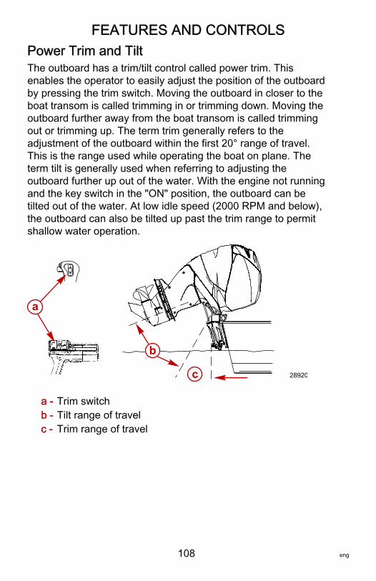
FEATURES AND CONTROLS
108 eng
Power Trim and TiltThe outboard has a trim/tilt control called power trim. Thisenables the operator to easily adjust the position of the outboardby pressing the trim switch. Moving the outboard in closer to theboat transom is called trimming in or trimming down. Moving theoutboard further away from the boat transom is called trimmingout or trimming up. The term trim generally refers to theadjustment of the outboard within the first 20° range of travel.This is the range used while operating the boat on plane. Theterm tilt is generally used when referring to adjusting theoutboard further up out of the water. With the engine not runningand the key switch in the "ON" position, the outboard can betilted out of the water. At low idle speed (2000 RPM and below),the outboard can also be tilted up past the trim range to permitshallow water operation.
a - Trim switchb - Tilt range of travelc - Trim range of travel
a
b
c 28920
FEATURES AND CONTROLS
eng 109
POWER TRIM OPERATIONWith most boats, operating around the middle of the trim rangewill give satisfactory results. However, to take full advantage ofthe trimming capability there may be times when you choose totrim the outboard all the way in or out. Along with animprovement in some performance aspects comes a greaterresponsibility for the operator, this being an awareness of somepotential control hazards.Consider the following lists carefully:1. Trimming in or down can:
• Lower the bow.• Result in quicker planing off, especially with a heavy load
or a stern heavy boat.• Generally improve the ride in choppy water.• In excess, can lower the bow of some boats to a point
where they begin to plow with their bow in the water whileon plane. This can result in an unexpected turn in eitherdirection (called bow steering or oversteering) if any turnis attempted, or if a significant wave is encountered.
! WARNINGOperating the boat at high speeds with the outboard trimmedtoo far under can create excessive bow steer, resulting in theoperator losing control of the boat. Install the trim limit pin in aposition that prevents excessive trim under and operate theboat in a safe manner.
2. Trimming out or up can:• Lift the bow higher out of the water.• Generally increase top speed.• Increase clearance over submerged objects or a shallow
bottom.• In excess, can cause boat porpoising (bouncing) or
propeller ventilation.• Cause engine overheating if any cooling water intake
holes are above the waterline.
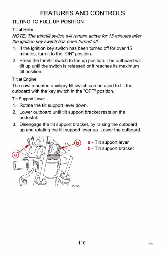
FEATURES AND CONTROLS
110 eng
TILTING TO FULL UP POSITIONTilt at HelmNOTE: The trim/tilt switch will remain active for 15 minutes afterthe ignition key switch has been turned off.1. If the ignition key switch has been turned off for over 15
minutes, turn it to the "ON" position.2. Press the trim/tilt switch to the up position. The outboard will
tilt up until the switch is released or it reaches its maximumtilt position.
Tilt at EngineThe cowl mounted auxiliary tilt switch can be used to tilt theoutboard with the key switch in the "OFF" position.Tilt Support Lever1. Rotate the tilt support lever down.2. Lower outboard until tilt support bracket rests on the
pedestal.3. Disengage the tilt support bracket, by raising the outboard
up and rotating the tilt support lever up. Lower the outboard.
a - Tilt support leverb - Tilt support bracket
a
b
28922
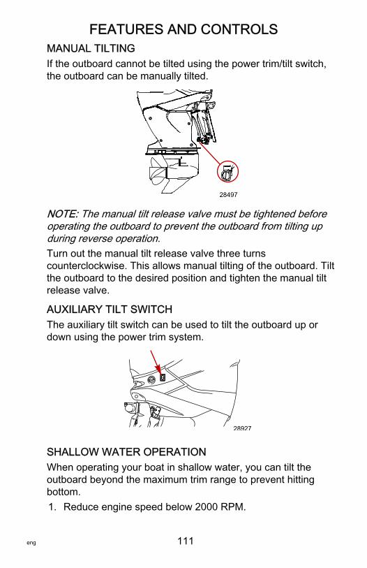
FEATURES AND CONTROLS
eng 111
MANUAL TILTINGIf the outboard cannot be tilted using the power trim/tilt switch,the outboard can be manually tilted.
28497
NOTE: The manual tilt release valve must be tightened beforeoperating the outboard to prevent the outboard from tilting upduring reverse operation.Turn out the manual tilt release valve three turnscounterclockwise. This allows manual tilting of the outboard. Tiltthe outboard to the desired position and tighten the manual tiltrelease valve.
AUXILIARY TILT SWITCHThe auxiliary tilt switch can be used to tilt the outboard up ordown using the power trim system.
28927
SHALLOW WATER OPERATIONWhen operating your boat in shallow water, you can tilt theoutboard beyond the maximum trim range to prevent hittingbottom.1. Reduce engine speed below 2000 RPM.
FEATURES AND CONTROLS
112 eng
2. Tilt outboard up. Make sure all the water intake holes staysubmerged at all times.
3. Operate the engine at slow speed only. With the outboardtilted past 20° trim limit, the warning horn will sound andengine speed will be automatically limited to approximately2000 RPM. The outboard must be tilted (trimmed) downbelow the maximum trim range to allow operation above2000 RPM.
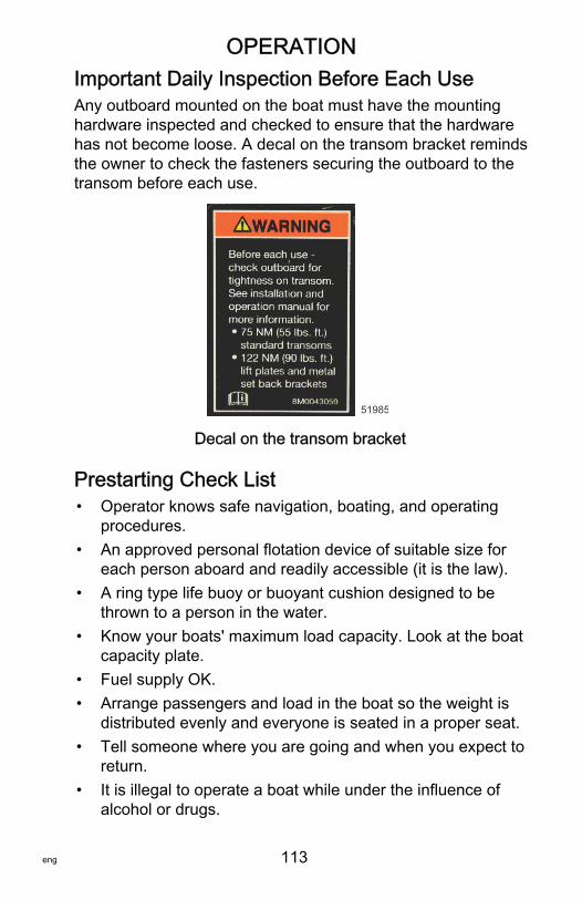
OPERATION
eng 113
Important Daily Inspection Before Each UseAny outboard mounted on the boat must have the mountinghardware inspected and checked to ensure that the hardwarehas not become loose. A decal on the transom bracket remindsthe owner to check the fasteners securing the outboard to thetransom before each use.
51985
Decal on the transom bracket
Prestarting Check List• Operator knows safe navigation, boating, and operating
procedures.• An approved personal flotation device of suitable size for
each person aboard and readily accessible (it is the law).• A ring type life buoy or buoyant cushion designed to be
thrown to a person in the water.• Know your boats' maximum load capacity. Look at the boat
capacity plate.• Fuel supply OK.• Arrange passengers and load in the boat so the weight is
distributed evenly and everyone is seated in a proper seat.• Tell someone where you are going and when you expect to
return.• It is illegal to operate a boat while under the influence of
alcohol or drugs.
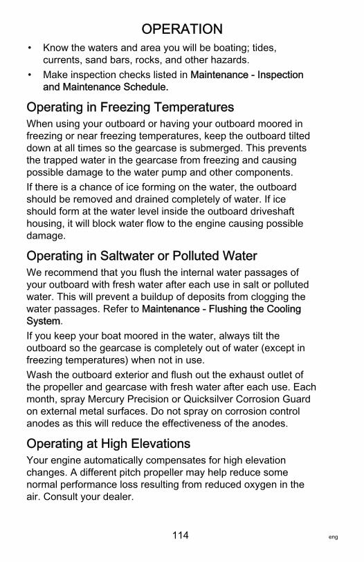
OPERATION
114 eng
• Know the waters and area you will be boating; tides,currents, sand bars, rocks, and other hazards.
• Make inspection checks listed in Maintenance ‑ Inspectionand Maintenance Schedule.
Operating in Freezing TemperaturesWhen using your outboard or having your outboard moored infreezing or near freezing temperatures, keep the outboard tilteddown at all times so the gearcase is submerged. This preventsthe trapped water in the gearcase from freezing and causingpossible damage to the water pump and other components.If there is a chance of ice forming on the water, the outboardshould be removed and drained completely of water. If iceshould form at the water level inside the outboard driveshafthousing, it will block water flow to the engine causing possibledamage.
Operating in Saltwater or Polluted WaterWe recommend that you flush the internal water passages ofyour outboard with fresh water after each use in salt or pollutedwater. This will prevent a buildup of deposits from clogging thewater passages. Refer to Maintenance ‑ Flushing the CoolingSystem.If you keep your boat moored in the water, always tilt theoutboard so the gearcase is completely out of water (except infreezing temperatures) when not in use.Wash the outboard exterior and flush out the exhaust outlet ofthe propeller and gearcase with fresh water after each use. Eachmonth, spray Mercury Precision or Quicksilver Corrosion Guardon external metal surfaces. Do not spray on corrosion controlanodes as this will reduce the effectiveness of the anodes.
Operating at High ElevationsYour engine automatically compensates for high elevationchanges. A different pitch propeller may help reduce somenormal performance loss resulting from reduced oxygen in theair. Consult your dealer.
OPERATION
eng 115
Effects of Elevation and Weather on PerformanceThe following conditions lower engine performance and cannotbe compensated by the engine fuel or electronic managementsystems:• Above sea level elevations• High temperature• Low barometric pressure• High humidity
These conditions above reduce air density to the engine, whichin turn lowers the following:• Boost pressure on supercharged engines• Horsepower and torque throughout the RPM range• Peak RPM• Cranking compression
EXAMPLE: An engine running at an elevation of 8,000 feet willhave over a 30% power loss while a loss of engine power on ahot and humid day could be as much as 14%. These lossesapply to normally aspirated and supercharged engines.Compensating for power robbing conditions:• Switch to lower pitch propeller.• Change gear ratio.
Some boat performance can be improved by dropping to a lowerpitch propeller, but engine performance will still remain lower. Insome cases, a gear ratio reduction may be more beneficial. Tooptimize engine performance, prop the engine to allow it tooperate at or near the top end of the recommended maximumRPM range at wide‑open throttle with a normal boat load.Other advantages to propeller or gear ratio changes:• Reduces the possibility of detonation• Enhances overall reliability and durability of the engine
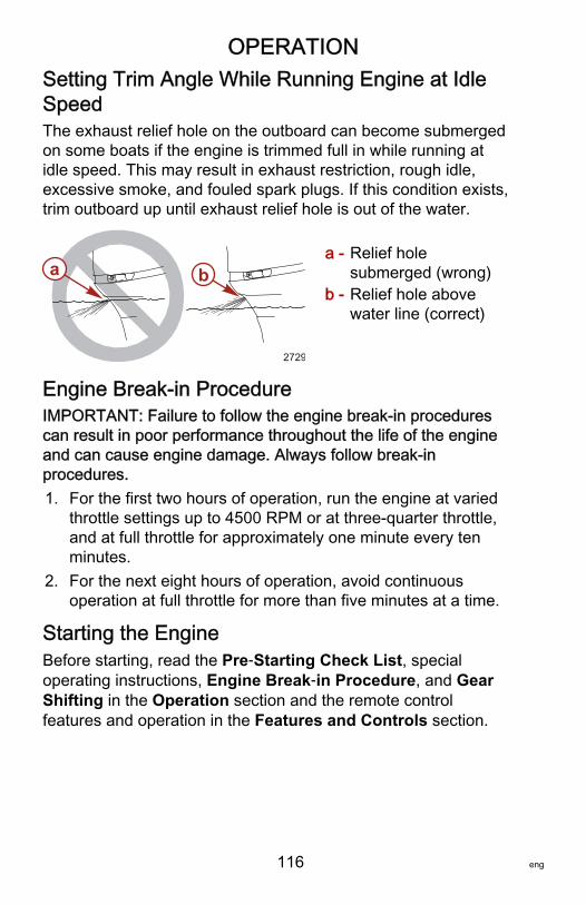
OPERATION
116 eng
Setting Trim Angle While Running Engine at IdleSpeedThe exhaust relief hole on the outboard can become submergedon some boats if the engine is trimmed full in while running atidle speed. This may result in exhaust restriction, rough idle,excessive smoke, and fouled spark plugs. If this condition exists,trim outboard up until exhaust relief hole is out of the water.
a - Relief holesubmerged (wrong)
b - Relief hole abovewater line (correct)
Engine Break‑in ProcedureIMPORTANT: Failure to follow the engine break‑in procedurescan result in poor performance throughout the life of the engineand can cause engine damage. Always follow break‑inprocedures.1. For the first two hours of operation, run the engine at varied
throttle settings up to 4500 RPM or at three‑quarter throttle,and at full throttle for approximately one minute every tenminutes.
2. For the next eight hours of operation, avoid continuousoperation at full throttle for more than five minutes at a time.
Starting the EngineBefore starting, read the Pre‑Starting Check List, specialoperating instructions, Engine Break‑in Procedure, and GearShifting in the Operation section and the remote controlfeatures and operation in the Features and Controls section.
a b
2729
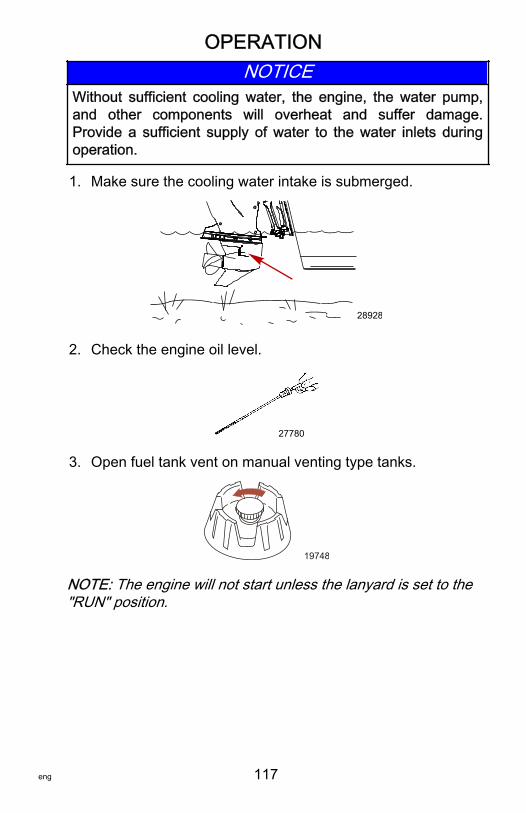
OPERATION
eng 117
NOTICEWithout sufficient cooling water, the engine, the water pump,and other components will overheat and suffer damage.Provide a sufficient supply of water to the water inlets duringoperation.
1. Make sure the cooling water intake is submerged.
28928
2. Check the engine oil level.
27780
3. Open fuel tank vent on manual venting type tanks.
19748
NOTE: The engine will not start unless the lanyard is set to the"RUN" position.
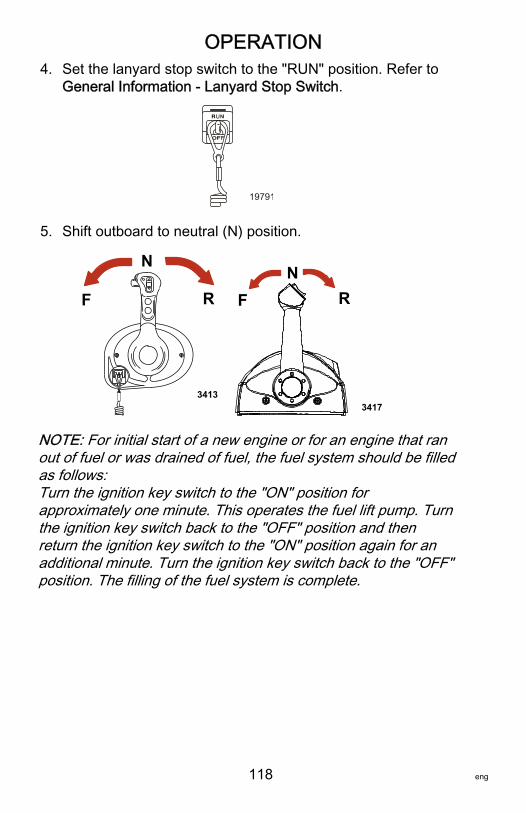
OPERATION
118 eng
4. Set the lanyard stop switch to the "RUN" position. Refer toGeneral Information ‑ Lanyard Stop Switch.
19791
5. Shift outboard to neutral (N) position.
F
N
R
3413
FN
R
3417
NOTE: For initial start of a new engine or for an engine that ranout of fuel or was drained of fuel, the fuel system should be filledas follows:Turn the ignition key switch to the "ON" position forapproximately one minute. This operates the fuel lift pump. Turnthe ignition key switch back to the "OFF" position and thenreturn the ignition key switch to the "ON" position again for anadditional minute. Turn the ignition key switch back to the "OFF"position. The filling of the fuel system is complete.
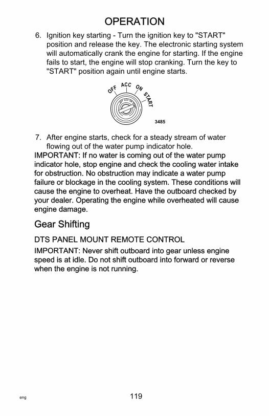
OPERATION
eng 119
6. Ignition key starting ‑ Turn the ignition key to "START"position and release the key. The electronic starting systemwill automatically crank the engine for starting. If the enginefails to start, the engine will stop cranking. Turn the key to"START" position again until engine starts.
START
OFF ACC ON
START
OFF ACC ON
3485
7. After engine starts, check for a steady stream of waterflowing out of the water pump indicator hole.
IMPORTANT: If no water is coming out of the water pumpindicator hole, stop engine and check the cooling water intakefor obstruction. No obstruction may indicate a water pumpfailure or blockage in the cooling system. These conditions willcause the engine to overheat. Have the outboard checked byyour dealer. Operating the engine while overheated will causeengine damage.
Gear ShiftingDTS PANEL MOUNT REMOTE CONTROLIMPORTANT: Never shift outboard into gear unless enginespeed is at idle. Do not shift outboard into forward or reversewhen the engine is not running.
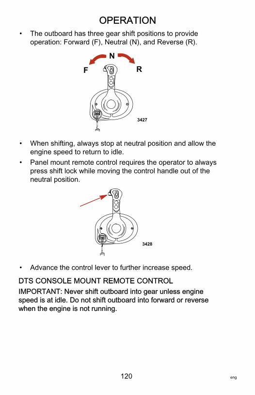
OPERATION
120 eng
• The outboard has three gear shift positions to provideoperation: Forward (F), Neutral (N), and Reverse (R).
3427
F
NR
• When shifting, always stop at neutral position and allow theengine speed to return to idle.
• Panel mount remote control requires the operator to alwayspress shift lock while moving the control handle out of theneutral position.
3428
• Advance the control lever to further increase speed.
DTS CONSOLE MOUNT REMOTE CONTROLIMPORTANT: Never shift outboard into gear unless enginespeed is at idle. Do not shift outboard into forward or reversewhen the engine is not running.
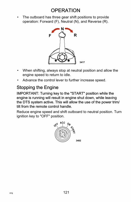
OPERATION
eng 121
• The outboard has three gear shift positions to provideoperation: Forward (F), Neutral (N), and Reverse (R).
FN
R
3417
• When shifting, always stop at neutral position and allow theengine speed to return to idle.
• Advance the control lever to further increase speed.
Stopping the EngineIMPORTANT: Turning key to the "START" position while theengine is running will result in engine shut down, while leavingthe DTS system active. This will allow the use of the power trim/tilt from the remote control handle.Reduce engine speed and shift outboard to neutral position. Turnignition key to "OFF" position.
START
OFF ACC ON
START
OFF ACC ON
3482
MAINTENANCE
122 eng
Outboard CareTo keep your outboard in the best operating condition, it isimportant that your outboard receive the periodic inspections andmaintenance listed in the Inspection and MaintenanceSchedule. We urge you to keep it maintained properly to ensurethe safety of you and your passengers, and retain itsdependability.Record maintenance performed in the Maintenance Log at theback of this book. Save all maintenance work orders andreceipts.
SELECTING REPLACEMENT PARTS FOR YOUROUTBOARDWe recommend using original Mercury Precision or Quicksilverreplacement parts and Genuine Lubricants.
EPA Emissions RegulationsAll new outboards manufactured by Mercury Marine are certifiedto the United States Environmental Protection Agency, asconforming to the requirements of the regulations for the controlof air pollution from new outboard motors. This certification iscontingent on certain adjustments set to factory standards. Forthis reason, the factory procedure for servicing the product mustbe strictly followed and, wherever practicable, returned to theoriginal intent of the design. Maintenance, replacement, or repairof the emission control devices and systems may be performedby any marine spark ignition (SI) engine repair establishment orindividual.
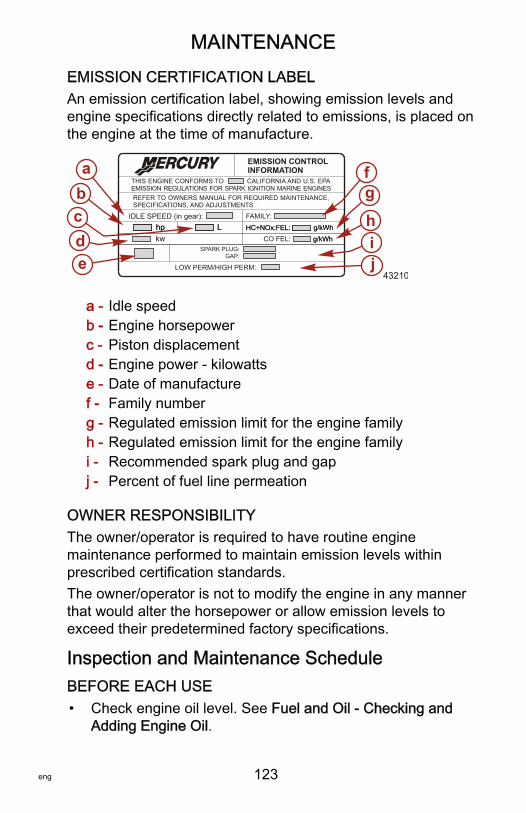
MAINTENANCE
eng 123
EMISSION CERTIFICATION LABELAn emission certification label, showing emission levels andengine specifications directly related to emissions, is placed onthe engine at the time of manufacture.
a - Idle speedb - Engine horsepowerc - Piston displacementd - Engine power ‑ kilowattse - Date of manufacturef - Family numberg - Regulated emission limit for the engine familyh - Regulated emission limit for the engine familyi - Recommended spark plug and gapj - Percent of fuel line permeation
OWNER RESPONSIBILITYThe owner/operator is required to have routine enginemaintenance performed to maintain emission levels withinprescribed certification standards.The owner/operator is not to modify the engine in any mannerthat would alter the horsepower or allow emission levels toexceed their predetermined factory specifications.
Inspection and Maintenance ScheduleBEFORE EACH USE• Check engine oil level. See Fuel and Oil ‑ Checking and
Adding Engine Oil.
SPARK PLUG:GAP:
EMISSION CONTROLINFORMATION
THIS ENGINE CONFORMS TOEMISSION REGULATIONS FOR SPARK IGNITION MARINE ENGINES
CALIFORNIA AND U.S. EPA
REFER TO OWNERS MANUAL FOR REQUIRED MAINTENANCE,SPECIFICATIONS, AND ADJUSTMENTS
IDLE SPEED (in gear): FAMILY:
HC+NOx:FEL:
LOW PERM/HIGH PERM:
g/kWhhp L
edcba f
g
hi
HC+NOx:FEL: g/kWhhp LCO FEL: g/kWhkw g/kWh
j43210
MAINTENANCE
124 eng
• Check that lanyard stop switch stops the engine.• Check the outboard for tightness to the boat transom. If any
looseness of the outboard or mounting fasteners exist,Tighten the outboard mounting fasteners to 75 Nm (55 lb‑ft).
• Visually inspect the fuel system for deterioration or leaks.• Check steering system for binding or loose components.• Visually check power steering fittings and hoses for leaks or
signs of damage. Check tie bar fasteners (multiple outboardrigs) for proper tightness.
• Check propeller blades for damage.
AFTER EACH USE• Flush out the outboard cooling system if operating in salt or
polluted water. See Flushing the Cooling System.• Wash off all salt deposits and flush out the exhaust outlet of
the propeller and gearcase with fresh water if operating insaltwater.
EVERY 100 HOURS OF USE OR ONCE YEARLY,WHICHEVER OCCURS FIRST• Change engine oil and replace the oil filter. The oil should
be changed more often when the engine is operated underadverse conditions such as extended trolling. See ChangingEngine Oil.
• Check the outboard for tightness to the boat transom. If anylooseness of the outboard or mounting fasteners exist,Tighten the outboard mounting fasteners to 75 Nm (55 lb‑ft).1.
• Inspect thermostat visually for corrosion and/or for a brokenspring. Make sure thermostat closes completely at roomtemperature.1.
• Check engine water separating fuel filter for contaminants.Clean and/or replace filter. See Fuel System.
• Check corrosion control anodes. Check more frequentlywhen used in saltwater. See Corrosion Control Anode.
1. These items should be serviced by an authorized dealer.
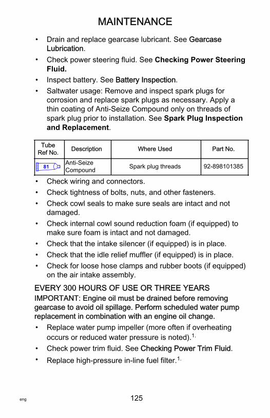
MAINTENANCE
eng 125
• Drain and replace gearcase lubricant. See GearcaseLubrication.
• Check power steering fluid. See Checking Power SteeringFluid.
• Inspect battery. See Battery Inspection.• Saltwater usage: Remove and inspect spark plugs for
corrosion and replace spark plugs as necessary. Apply athin coating of Anti‑Seize Compound only on threads ofspark plug prior to installation. See Spark Plug Inspectionand Replacement.
TubeRef No. Description Where Used Part No.
81 Anti-SeizeCompound Spark plug threads 92-898101385
• Check wiring and connectors.• Check tightness of bolts, nuts, and other fasteners.• Check cowl seals to make sure seals are intact and not
damaged.• Check internal cowl sound reduction foam (if equipped) to
make sure foam is intact and not damaged.• Check that the intake silencer (if equipped) is in place.• Check that the idle relief muffler (if equipped) is in place.• Check for loose hose clamps and rubber boots (if equipped)
on the air intake assembly.
EVERY 300 HOURS OF USE OR THREE YEARSIMPORTANT: Engine oil must be drained before removinggearcase to avoid oil spillage. Perform scheduled water pumpreplacement in combination with an engine oil change.• Replace water pump impeller (more often if overheating
occurs or reduced water pressure is noted).1.
• Check power trim fluid. See Checking Power Trim Fluid.• Replace high‑pressure in‑line fuel filter.1.
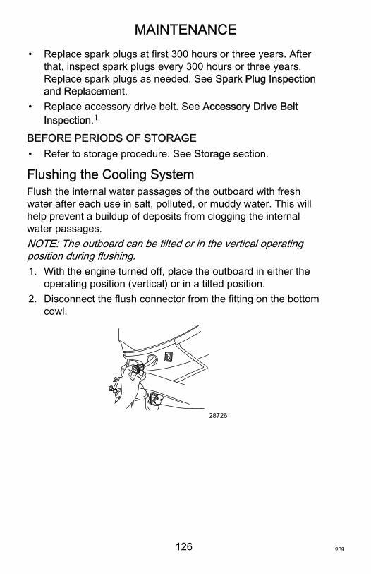
MAINTENANCE
126 eng
• Replace spark plugs at first 300 hours or three years. Afterthat, inspect spark plugs every 300 hours or three years.Replace spark plugs as needed. See Spark Plug Inspectionand Replacement.
• Replace accessory drive belt. See Accessory Drive BeltInspection.1.
BEFORE PERIODS OF STORAGE• Refer to storage procedure. See Storage section.
Flushing the Cooling SystemFlush the internal water passages of the outboard with freshwater after each use in salt, polluted, or muddy water. This willhelp prevent a buildup of deposits from clogging the internalwater passages.NOTE: The outboard can be tilted or in the vertical operatingposition during flushing.1. With the engine turned off, place the outboard in either the
operating position (vertical) or in a tilted position.2. Disconnect the flush connector from the fitting on the bottom
cowl.
28726
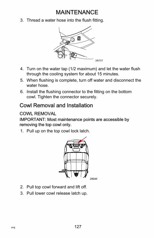
MAINTENANCE
eng 127
3. Thread a water hose into the flush fitting.
28727
4. Turn on the water tap (1/2 maximum) and let the water flushthrough the cooling system for about 15 minutes.
5. When flushing is complete, turn off water and disconnect thewater hose.
6. Install the flushing connector to the fitting on the bottomcowl. Tighten the connector securely.
Cowl Removal and InstallationCOWL REMOVALIMPORTANT: Most maintenance points are accessible byremoving the top cowl only.1. Pull up on the top cowl lock latch.
28946
2. Pull top cowl forward and lift off.3. Pull lower cowl release latch up.
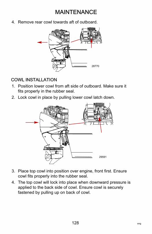
MAINTENANCE
128 eng
4. Remove rear cowl towards aft of outboard.
28770
COWL INSTALLATION1. Position lower cowl from aft side of outboard. Make sure it
fits properly in the rubber seal.2. Lock cowl in place by pulling lower cowl latch down.
29591
3. Place top cowl into position over engine, front first. Ensurecowl fits properly into the rubber seal.
4. The top cowl will lock into place when downward pressure isapplied to the back side of cowl. Ensure cowl is securelyfastened by pulling up on back of cowl.
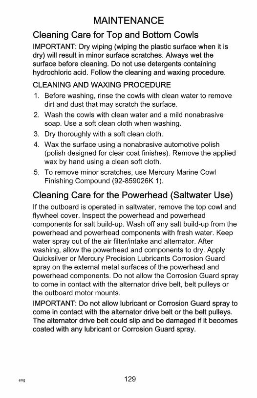
MAINTENANCE
eng 129
Cleaning Care for Top and Bottom CowlsIMPORTANT: Dry wiping (wiping the plastic surface when it isdry) will result in minor surface scratches. Always wet thesurface before cleaning. Do not use detergents containinghydrochloric acid. Follow the cleaning and waxing procedure.
CLEANING AND WAXING PROCEDURE1. Before washing, rinse the cowls with clean water to remove
dirt and dust that may scratch the surface.2. Wash the cowls with clean water and a mild nonabrasive
soap. Use a soft clean cloth when washing.3. Dry thoroughly with a soft clean cloth.4. Wax the surface using a nonabrasive automotive polish
(polish designed for clear coat finishes). Remove the appliedwax by hand using a clean soft cloth.
5. To remove minor scratches, use Mercury Marine CowlFinishing Compound (92‑859026K 1).
Cleaning Care for the Powerhead (Saltwater Use)If the outboard is operated in saltwater, remove the top cowl andflywheel cover. Inspect the powerhead and powerheadcomponents for salt build‑up. Wash off any salt build‑up from thepowerhead and powerhead components with fresh water. Keepwater spray out of the air filter/intake and alternator. Afterwashing, allow the powerhead and components to dry. ApplyQuicksilver or Mercury Precision Lubricants Corrosion Guardspray on the external metal surfaces of the powerhead andpowerhead components. Do not allow the Corrosion Guard sprayto come in contact with the alternator drive belt, belt pulleys orthe outboard motor mounts.IMPORTANT: Do not allow lubricant or Corrosion Guard spray tocome in contact with the alternator drive belt or the belt pulleys.The alternator drive belt could slip and be damaged if it becomescoated with any lubricant or Corrosion Guard spray.
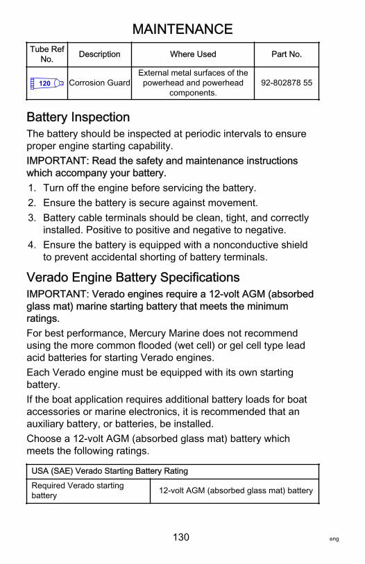
MAINTENANCE
130 eng
Tube RefNo. Description Where Used Part No.
120 Corrosion GuardExternal metal surfaces of thepowerhead and powerhead
components.92-802878 55
Battery InspectionThe battery should be inspected at periodic intervals to ensureproper engine starting capability.IMPORTANT: Read the safety and maintenance instructionswhich accompany your battery.1. Turn off the engine before servicing the battery.2. Ensure the battery is secure against movement.3. Battery cable terminals should be clean, tight, and correctly
installed. Positive to positive and negative to negative.4. Ensure the battery is equipped with a nonconductive shield
to prevent accidental shorting of battery terminals.
Verado Engine Battery SpecificationsIMPORTANT: Verado engines require a 12‑volt AGM (absorbedglass mat) marine starting battery that meets the minimumratings.For best performance, Mercury Marine does not recommendusing the more common flooded (wet cell) or gel cell type leadacid batteries for starting Verado engines.Each Verado engine must be equipped with its own startingbattery.If the boat application requires additional battery loads for boataccessories or marine electronics, it is recommended that anauxiliary battery, or batteries, be installed.Choose a 12‑volt AGM (absorbed glass mat) battery whichmeets the following ratings.
USA (SAE) Verado Starting Battery Rating
Required Verado startingbattery 12‑volt AGM (absorbed glass mat) battery
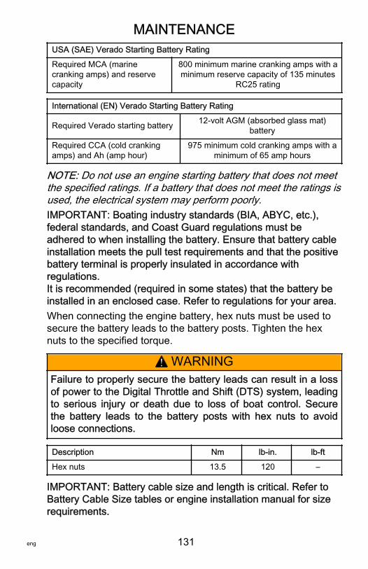
MAINTENANCE
eng 131
USA (SAE) Verado Starting Battery Rating
Required MCA (marinecranking amps) and reservecapacity
800 minimum marine cranking amps with aminimum reserve capacity of 135 minutes
RC25 rating
International (EN) Verado Starting Battery Rating
Required Verado starting battery 12‑volt AGM (absorbed glass mat)battery
Required CCA (cold crankingamps) and Ah (amp hour)
975 minimum cold cranking amps with aminimum of 65 amp hours
NOTE: Do not use an engine starting battery that does not meetthe specified ratings. If a battery that does not meet the ratings isused, the electrical system may perform poorly.IMPORTANT: Boating industry standards (BIA, ABYC, etc.),federal standards, and Coast Guard regulations must beadhered to when installing the battery. Ensure that battery cableinstallation meets the pull test requirements and that the positivebattery terminal is properly insulated in accordance withregulations.It is recommended (required in some states) that the battery beinstalled in an enclosed case. Refer to regulations for your area.When connecting the engine battery, hex nuts must be used tosecure the battery leads to the battery posts. Tighten the hexnuts to the specified torque.
! WARNINGFailure to properly secure the battery leads can result in a lossof power to the Digital Throttle and Shift (DTS) system, leadingto serious injury or death due to loss of boat control. Securethe battery leads to the battery posts with hex nuts to avoidloose connections.
Description Nm lb‑in. lb‑ft
Hex nuts 13.5 120 –
IMPORTANT: Battery cable size and length is critical. Refer toBattery Cable Size tables or engine installation manual for sizerequirements.
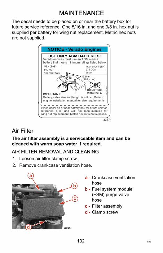
MAINTENANCE
132 eng
The decal needs to be placed on or near the battery box forfuture service reference. One 5/16 in. and one 3/8 in. hex nut issupplied per battery for wing nut replacement. Metric hex nutsare not supplied.
NOTICE - Verado EnginesUSE ONLY AGM BATTERIES!
Verado engines must use an AGM marinebattery that meets minimum ratings listed below.
IMPORTANT:Battery cable size and length is critical. Refer toengine installation manual for size requirements.
Place decal on or near battery box for future servicereference. 5/16” and 3/8” hex nuts supplied forwing nut replacement. Metric hex nuts not supplied.
DO NOT USEWING NUTS.
13.5Nm(120 lbs. in.)
USA (SAE)800 MCA135 min RC25
International (EN)975 CCA65 Ah
8M00
3405
0
33871
Air FilterThe air filter assembly is a serviceable item and can becleaned with warm soap water if required.AIR FILTER REMOVAL AND CLEANING1. Loosen air filter clamp screw.2. Remove crankcase ventilation hose.
a - Crankcase ventilationhose
b - Fuel system module(FSM) purge valvehose
c - Filter assemblyd - Clamp screw
3664
a
b
c
d
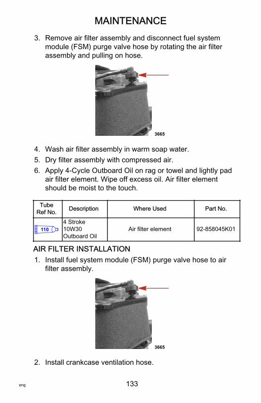
MAINTENANCE
eng 133
3. Remove air filter assembly and disconnect fuel systemmodule (FSM) purge valve hose by rotating the air filterassembly and pulling on hose.
3665
4. Wash air filter assembly in warm soap water.5. Dry filter assembly with compressed air.6. Apply 4‑Cycle Outboard Oil on rag or towel and lightly pad
air filter element. Wipe off excess oil. Air filter elementshould be moist to the touch.
TubeRef No. Description Where Used Part No.
1104 Stroke10W30Outboard Oil
Air filter element 92-858045K01
AIR FILTER INSTALLATION1. Install fuel system module (FSM) purge valve hose to air
filter assembly.
3665
2. Install crankcase ventilation hose.
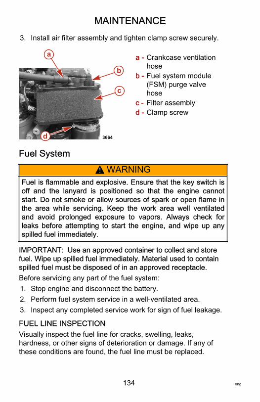
MAINTENANCE
134 eng
3. Install air filter assembly and tighten clamp screw securely.
a - Crankcase ventilationhose
b - Fuel system module(FSM) purge valvehose
c - Filter assemblyd - Clamp screw
Fuel System
! WARNINGFuel is flammable and explosive. Ensure that the key switch isoff and the lanyard is positioned so that the engine cannotstart. Do not smoke or allow sources of spark or open flame inthe area while servicing. Keep the work area well ventilatedand avoid prolonged exposure to vapors. Always check forleaks before attempting to start the engine, and wipe up anyspilled fuel immediately.
IMPORTANT: Use an approved container to collect and storefuel. Wipe up spilled fuel immediately. Material used to containspilled fuel must be disposed of in an approved receptacle.Before servicing any part of the fuel system:1. Stop engine and disconnect the battery.2. Perform fuel system service in a well‑ventilated area.3. Inspect any completed service work for sign of fuel leakage.
FUEL LINE INSPECTIONVisually inspect the fuel line for cracks, swelling, leaks,hardness, or other signs of deterioration or damage. If any ofthese conditions are found, the fuel line must be replaced.
3664
a
b
c
d
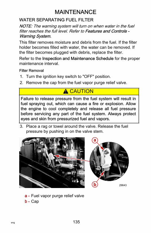
MAINTENANCE
eng 135
WATER SEPARATING FUEL FILTERNOTE: The warning system will turn on when water in the fuelfilter reaches the full level. Refer to Features and Controls ‑Warning System.This filter removes moisture and debris from the fuel. If the filterholder becomes filled with water, the water can be removed. Ifthe filter becomes plugged with debris, replace the filter.Refer to the Inspection and Maintenance Schedule for the propermaintenance interval.Filter Removal1. Turn the ignition key switch to "OFF" position.2. Remove the cap from the fuel vapor purge relief valve.
! CAUTIONFailure to release pressure from the fuel system will result infuel spraying out, which can cause a fire or explosion. Allowthe engine to cool completely and release all fuel pressurebefore servicing any part of the fuel system. Always protecteyes and skin from pressurized fuel and vapors.
3. Place a rag or towel around the valve. Release the fuelpressure by pushing in on the valve stem.
a - Fuel vapor purge relief valveb - Cap
a
b 29643
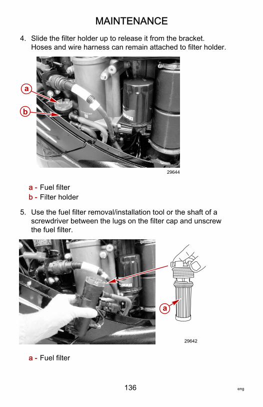
MAINTENANCE
136 eng
4. Slide the filter holder up to release it from the bracket.Hoses and wire harness can remain attached to filter holder.
a - Fuel filterb - Filter holder
5. Use the fuel filter removal/installation tool or the shaft of ascrewdriver between the lugs on the filter cap and unscrewthe fuel filter.
a - Fuel filter
b
29644
a
a
29642
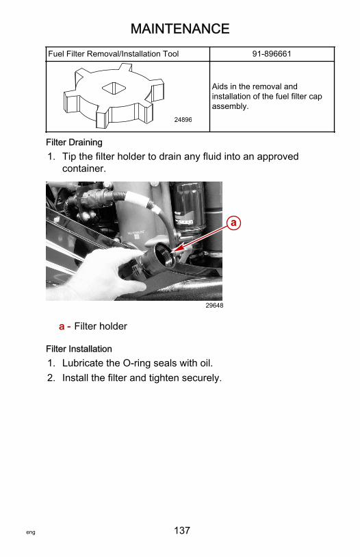
MAINTENANCE
eng 137
Fuel Filter Removal/Installation Tool 91‑896661
24896
Aids in the removal andinstallation of the fuel filter capassembly.
Filter Draining1. Tip the filter holder to drain any fluid into an approved
container.
a - Filter holder
Filter Installation1. Lubricate the O‑ring seals with oil.2. Install the filter and tighten securely.
a
29648
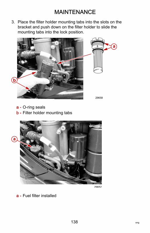
MAINTENANCE
138 eng
3. Place the filter holder mounting tabs into the slots on thebracket and push down on the filter holder to slide themounting tabs into the lock position.
a - O‑ring sealsb - Filter holder mounting tabs
a - Fuel filter installed
29658
b
a
a
29652
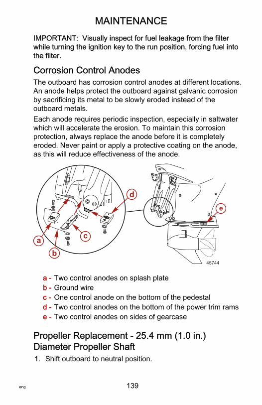
MAINTENANCE
eng 139
IMPORTANT: Visually inspect for fuel leakage from the filterwhile turning the ignition key to the run position, forcing fuel intothe filter.
Corrosion Control AnodesThe outboard has corrosion control anodes at different locations.An anode helps protect the outboard against galvanic corrosionby sacrificing its metal to be slowly eroded instead of theoutboard metals.Each anode requires periodic inspection, especially in saltwaterwhich will accelerate the erosion. To maintain this corrosionprotection, always replace the anode before it is completelyeroded. Never paint or apply a protective coating on the anode,as this will reduce effectiveness of the anode.
a - Two control anodes on splash plateb - Ground wirec - One control anode on the bottom of the pedestald - Two control anodes on the bottom of the power trim ramse - Two control anodes on sides of gearcase
Propeller Replacement ‑ 25.4 mm (1.0 in.)Diameter Propeller Shaft1. Shift outboard to neutral position.
a c
b
de
45744
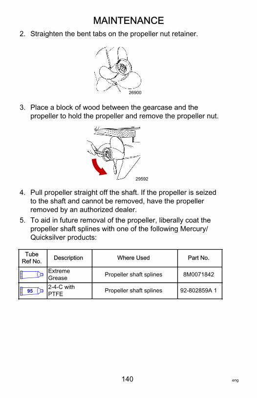
MAINTENANCE
140 eng
2. Straighten the bent tabs on the propeller nut retainer.
26900
3. Place a block of wood between the gearcase and thepropeller to hold the propeller and remove the propeller nut.
29592
4. Pull propeller straight off the shaft. If the propeller is seizedto the shaft and cannot be removed, have the propellerremoved by an authorized dealer.
5. To aid in future removal of the propeller, liberally coat thepropeller shaft splines with one of the following Mercury/Quicksilver products:
TubeRef No. Description Where Used Part No.
ExtremeGrease Propeller shaft splines 8M0071842
952-4-C withPTFE Propeller shaft splines 92-802859A 1
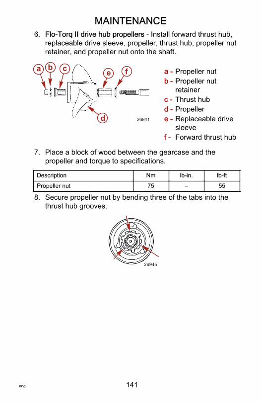
MAINTENANCE
eng 141
6. Flo‑Torq II drive hub propellers ‑ Install forward thrust hub,replaceable drive sleeve, propeller, thrust hub, propeller nutretainer, and propeller nut onto the shaft.
a - Propeller nutb - Propeller nut
retainerc - Thrust hubd - Propellere - Replaceable drive
sleevef - Forward thrust hub
7. Place a block of wood between the gearcase and thepropeller and torque to specifications.
Description Nm lb‑in. lb‑ft
Propeller nut 75 – 55
8. Secure propeller nut by bending three of the tabs into thethrust hub grooves.
26945
a b c
d
e f
26941
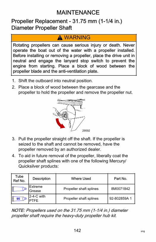
MAINTENANCE
142 eng
Propeller Replacement ‑ 31.75 mm (1‑1/4 in.)Diameter Propeller Shaft
! WARNINGRotating propellers can cause serious injury or death. Neveroperate the boat out of the water with a propeller installed.Before installing or removing a propeller, place the drive unit inneutral and engage the lanyard stop switch to prevent theengine from starting. Place a block of wood between thepropeller blade and the anti‑ventilation plate.
1. Shift the outboard into neutral position.2. Place a block of wood between the gearcase and the
propeller to hold the propeller and remove the propeller nut.
29592
3. Pull the propeller straight off the shaft. If the propeller isseized to the shaft and cannot be removed, have thepropeller removed by an authorized dealer.
4. To aid in future removal of the propeller, liberally coat thepropeller shaft splines with one of the following Mercury/Quicksilver products:
TubeRef No. Description Where Used Part No.
ExtremeGrease Propeller shaft splines 8M0071842
952-4-C withPTFE Propeller shaft splines 92-802859A 1
NOTE: Propellers used on the 31.75 mm (1‑1/4 in.) diameterpropeller shaft require the heavy‑duty propeller hub kit.
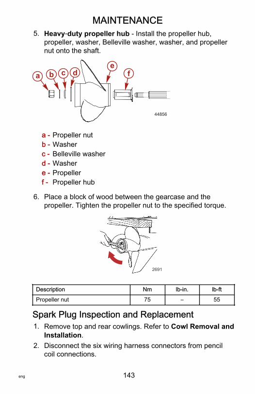
MAINTENANCE
eng 143
5. Heavy‑duty propeller hub ‑ Install the propeller hub,propeller, washer, Belleville washer, washer, and propellernut onto the shaft.
a - Propeller nutb - Washerc - Belleville washerd - Washere - Propellerf - Propeller hub
6. Place a block of wood between the gearcase and thepropeller. Tighten the propeller nut to the specified torque.
2691
Description Nm lb‑in. lb‑ft
Propeller nut 75 – 55
Spark Plug Inspection and Replacement1. Remove top and rear cowlings. Refer to Cowl Removal and
Installation.2. Disconnect the six wiring harness connectors from pencil
coil connections.
a b c de
f
44856
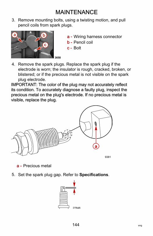
MAINTENANCE
144 eng
3. Remove mounting bolts, using a twisting motion, and pullpencil coils from spark plugs.
a - Wiring harness connectorb - Pencil coilc - Bolt
4. Remove the spark plugs. Replace the spark plug if theelectrode is worn; the insulator is rough, cracked, broken, orblistered; or if the precious metal is not visible on the sparkplug electrode.
IMPORTANT: The color of the plug may not accurately reflectits condition. To accurately diagnose a faulty plug, inspect theprecious metal on the plug's electrode. If no precious metal isvisible, replace the plug.
a - Precious metal
5. Set the spark plug gap. Refer to Specifications.
27848
a b
c
3658
a
9381
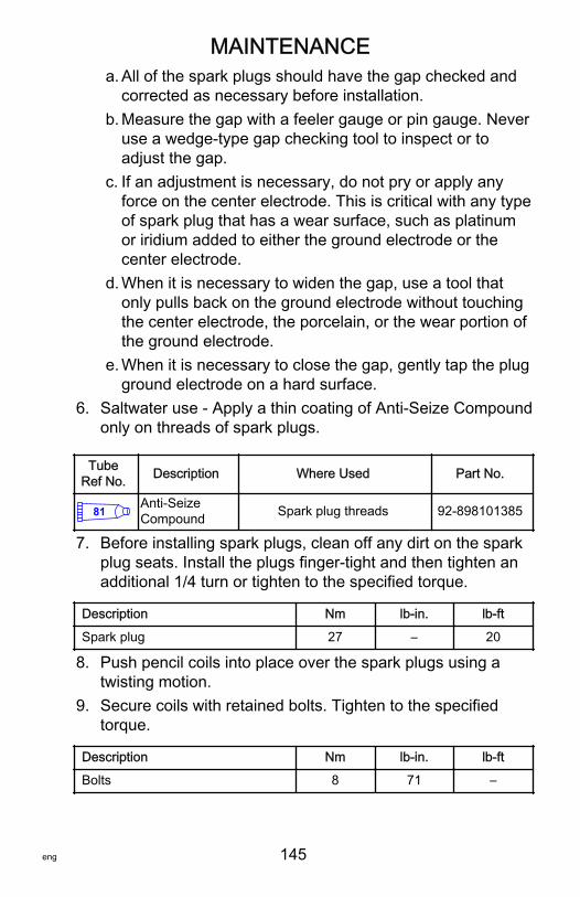
MAINTENANCE
eng 145
a. All of the spark plugs should have the gap checked andcorrected as necessary before installation.
b. Measure the gap with a feeler gauge or pin gauge. Neveruse a wedge‑type gap checking tool to inspect or toadjust the gap.
c. If an adjustment is necessary, do not pry or apply anyforce on the center electrode. This is critical with any typeof spark plug that has a wear surface, such as platinumor iridium added to either the ground electrode or thecenter electrode.
d. When it is necessary to widen the gap, use a tool thatonly pulls back on the ground electrode without touchingthe center electrode, the porcelain, or the wear portion ofthe ground electrode.
e. When it is necessary to close the gap, gently tap the plugground electrode on a hard surface.
6. Saltwater use ‑ Apply a thin coating of Anti‑Seize Compoundonly on threads of spark plugs.
TubeRef No. Description Where Used Part No.
81 Anti-SeizeCompound Spark plug threads 92-898101385
7. Before installing spark plugs, clean off any dirt on the sparkplug seats. Install the plugs finger‑tight and then tighten anadditional 1/4 turn or tighten to the specified torque.
Description Nm lb‑in. lb‑ft
Spark plug 27 – 20
8. Push pencil coils into place over the spark plugs using atwisting motion.
9. Secure coils with retained bolts. Tighten to the specifiedtorque.
Description Nm lb‑in. lb‑ft
Bolts 8 71 –
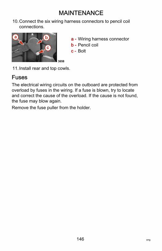
MAINTENANCE
146 eng
10.Connect the six wiring harness connectors to pencil coilconnections.
a - Wiring harness connectorb - Pencil coilc - Bolt
11. Install rear and top cowls.
FusesThe electrical wiring circuits on the outboard are protected fromoverload by fuses in the wiring. If a fuse is blown, try to locateand correct the cause of the overload. If the cause is not found,the fuse may blow again.Remove the fuse puller from the holder.
a b
c
3658
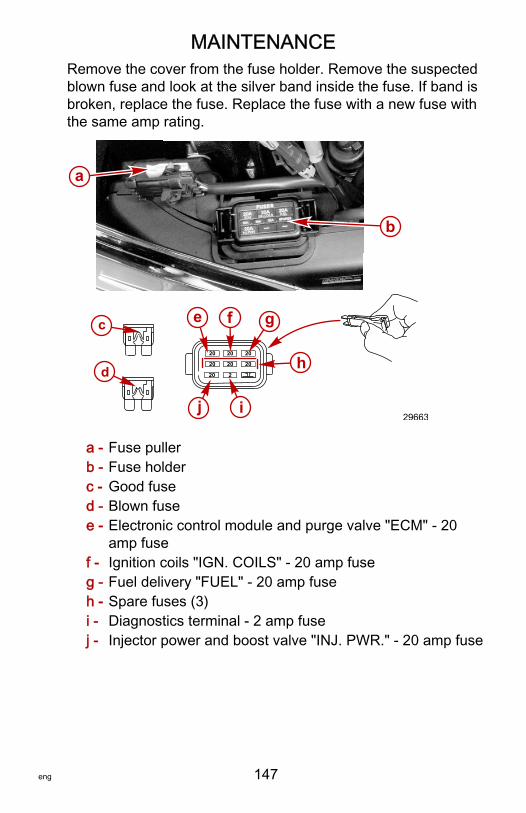
MAINTENANCE
eng 147
Remove the cover from the fuse holder. Remove the suspectedblown fuse and look at the silver band inside the fuse. If band isbroken, replace the fuse. Replace the fuse with a new fuse withthe same amp rating.
a - Fuse pullerb - Fuse holderc - Good fused - Blown fusee - Electronic control module and purge valve "ECM" ‑ 20
amp fusef - Ignition coils "IGN. COILS" ‑ 20 amp fuseg - Fuel delivery "FUEL" ‑ 20 amp fuseh - Spare fuses (3)i - Diagnostics terminal ‑ 2 amp fusej - Injector power and boost valve "INJ. PWR." ‑ 20 amp fuse
20 20 20
20 20 20
20
e g
h
j
2
i
fc
d
a
b
29663
MAINTENANCE
148 eng
DTS Wiring System
! WARNINGSplicing or probing will damage the wire insulation allowingwater to enter the wiring. Water intrusion may lead to wiringfailure and loss of throttle and shift control. To avoid thepossibility of serious injury or death from loss of boat control,do not splice or probe into any wire insulation of the DTSsystem.
• Verify the harnesses are not routed near sharp edges, hotsurfaces, or moving parts.
• Verify all unused connectors and receptacles are coveredwith a weather cap.
• Verify the harnesses are fastened along the routing path.
Accessory Drive Belt InspectionInspect the accessory drive belt and have it replaced by anauthorized dealer if any of the following conditions are found.• Cracks in the back of the belt or in the base of V grooves.• Excessive wear at the roots of the grooves.• Rubber portion swollen by oil.• Belt surfaces roughened.• Signs of wear on edges or outer surfaces of belt.
Checking Power Trim Fluid1. Tilt outboard to the full up position.2. Rotate the tilt support bracket down.3. Lower outboard until tilt support bracket rests on pedestal.
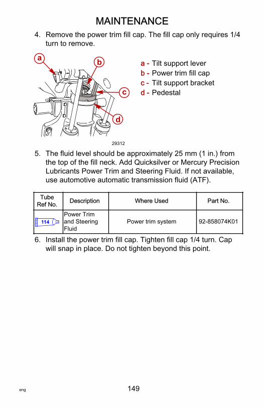
MAINTENANCE
eng 149
4. Remove the power trim fill cap. The fill cap only requires 1/4turn to remove.
a - Tilt support leverb - Power trim fill capc - Tilt support bracketd - Pedestal
5. The fluid level should be approximately 25 mm (1 in.) fromthe top of the fill neck. Add Quicksilver or Mercury PrecisionLubricants Power Trim and Steering Fluid. If not available,use automotive automatic transmission fluid (ATF).
TubeRef No. Description Where Used Part No.
114Power Trimand SteeringFluid
Power trim system 92-858074K01
6. Install the power trim fill cap. Tighten fill cap 1/4 turn. Capwill snap in place. Do not tighten beyond this point.
a
c
d
b
29312
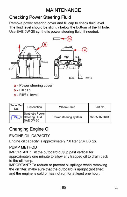
MAINTENANCE
150 eng
Checking Power Steering FluidRemove power steering cover and fill cap to check fluid level.The fluid level should be slightly below the bottom of the fill hole.Use SAE 0W‑30 synthetic power steering fluid, if needed.
a - Power steering coverb - Fill capc - Fill/full level
Tube RefNo. Description Where Used Part No.
138Synthetic PowerSteering FluidSAE 0W-30
Power steering system 92-858076K01
Changing Engine OilENGINE OIL CAPACITYEngine oil capacity is approximately 7.0 liter (7.4 US qt).
PUMP METHODIMPORTANT: Tilt the outboard out/up past vertical forapproximately one minute to allow any trapped oil to drain backto the oil sump.IMPORTANT: To reduce or prevent oil spillage when removingthe oil filter, make sure that the outboard is upright (not tilted)and the engine is cold or has not run for at least one hour.
ab
c
29315
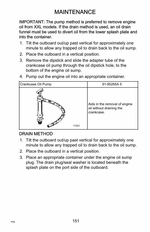
MAINTENANCE
eng 151
IMPORTANT: The pump method is preferred to remove engineoil from XXL models. If the drain method is used, an oil drainfunnel must be used to divert oil from the lower splash plate andinto the container.1. Tilt the outboard out/up past vertical for approximately one
minute to allow any trapped oil to drain back to the oil sump.2. Place the outboard in a vertical position.3. Remove the dipstick and slide the adapter tube of the
crankcase oil pump through the oil dipstick hole, to thebottom of the engine oil sump.
4. Pump out the engine oil into an appropriate container.
Crankcase Oil Pump 91‑90265A 5
11591
Aids in the removal of engineoil without draining thecrankcase.
DRAIN METHOD1. Tilt the outboard out/up past vertical for approximately one
minute to allow any trapped oil to drain back to the oil sump.2. Place the outboard in a vertical position.3. Place an appropriate container under the engine oil sump
plug. The drain plug/seal washer is located beneath thesplash plate on the port side of the outboard.
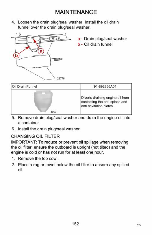
MAINTENANCE
152 eng
4. Loosen the drain plug/seal washer. Install the oil drainfunnel over the drain plug/seal washer.
a - Drain plug/seal washerb - Oil drain funnel
Oil Drain Funnel 91‑892866A01
4993
Diverts draining engine oil fromcontacting the anti‑splash andanti‑cavitation plates.
5. Remove drain plug/seal washer and drain the engine oil intoa container.
6. Install the drain plug/seal washer.
CHANGING OIL FILTERIMPORTANT: To reduce or prevent oil spillage when removingthe oil filter, ensure the outboard is upright (not tilted) and theengine is cold or has not run for at least one hour.1. Remove the top cowl.2. Place a rag or towel below the oil filter to absorb any spilled
oil.
ba
28778
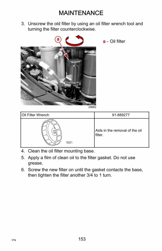
MAINTENANCE
eng 153
3. Unscrew the old filter by using an oil filter wrench tool andturning the filter counterclockwise.
a - Oil filter
Oil Filter Wrench 91‑889277
5221
Aids in the removal of the oilfilter.
4. Clean the oil filter mounting base.5. Apply a film of clean oil to the filter gasket. Do not use
grease.6. Screw the new filter on until the gasket contacts the base,
then tighten the filter another 3/4 to 1 turn.
a
29662
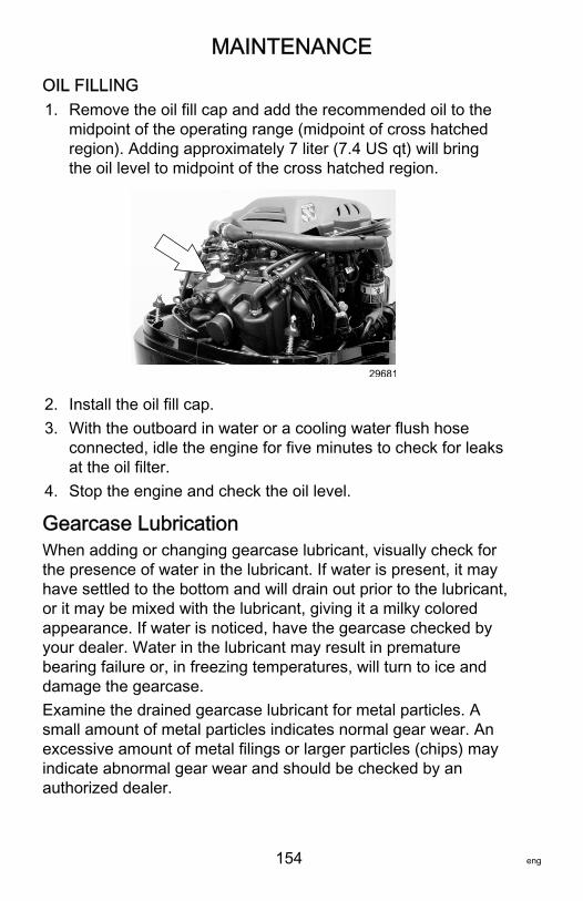
MAINTENANCE
154 eng
OIL FILLING1. Remove the oil fill cap and add the recommended oil to the
midpoint of the operating range (midpoint of cross hatchedregion). Adding approximately 7 liter (7.4 US qt) will bringthe oil level to midpoint of the cross hatched region.
29681
2. Install the oil fill cap.3. With the outboard in water or a cooling water flush hose
connected, idle the engine for five minutes to check for leaksat the oil filter.
4. Stop the engine and check the oil level.
Gearcase LubricationWhen adding or changing gearcase lubricant, visually check forthe presence of water in the lubricant. If water is present, it mayhave settled to the bottom and will drain out prior to the lubricant,or it may be mixed with the lubricant, giving it a milky coloredappearance. If water is noticed, have the gearcase checked byyour dealer. Water in the lubricant may result in prematurebearing failure or, in freezing temperatures, will turn to ice anddamage the gearcase.Examine the drained gearcase lubricant for metal particles. Asmall amount of metal particles indicates normal gear wear. Anexcessive amount of metal filings or larger particles (chips) mayindicate abnormal gear wear and should be checked by anauthorized dealer.
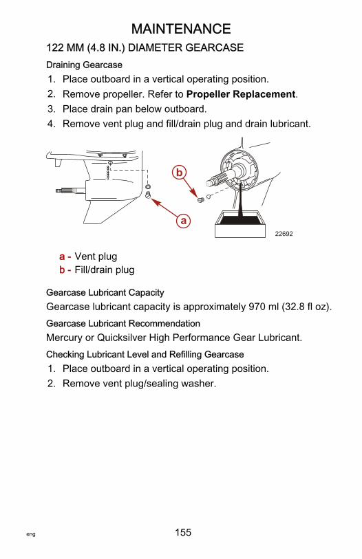
MAINTENANCE
eng 155
122 MM (4.8 IN.) DIAMETER GEARCASEDraining Gearcase1. Place outboard in a vertical operating position.2. Remove propeller. Refer to Propeller Replacement.3. Place drain pan below outboard.4. Remove vent plug and fill/drain plug and drain lubricant.
a - Vent plugb - Fill/drain plug
Gearcase Lubricant CapacityGearcase lubricant capacity is approximately 970 ml (32.8 fl oz).Gearcase Lubricant RecommendationMercury or Quicksilver High Performance Gear Lubricant.Checking Lubricant Level and Refilling Gearcase1. Place outboard in a vertical operating position.2. Remove vent plug/sealing washer.
a
b
22692
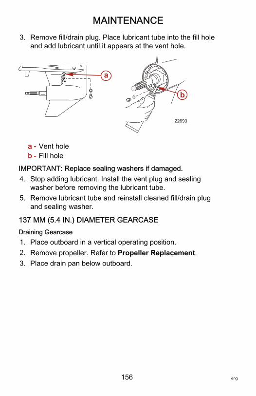
MAINTENANCE
156 eng
3. Remove fill/drain plug. Place lubricant tube into the fill holeand add lubricant until it appears at the vent hole.
a - Vent holeb - Fill hole
IMPORTANT: Replace sealing washers if damaged.4. Stop adding lubricant. Install the vent plug and sealing
washer before removing the lubricant tube.5. Remove lubricant tube and reinstall cleaned fill/drain plug
and sealing washer.
137 MM (5.4 IN.) DIAMETER GEARCASEDraining Gearcase1. Place outboard in a vertical operating position.2. Remove propeller. Refer to Propeller Replacement.3. Place drain pan below outboard.
a
b
22693
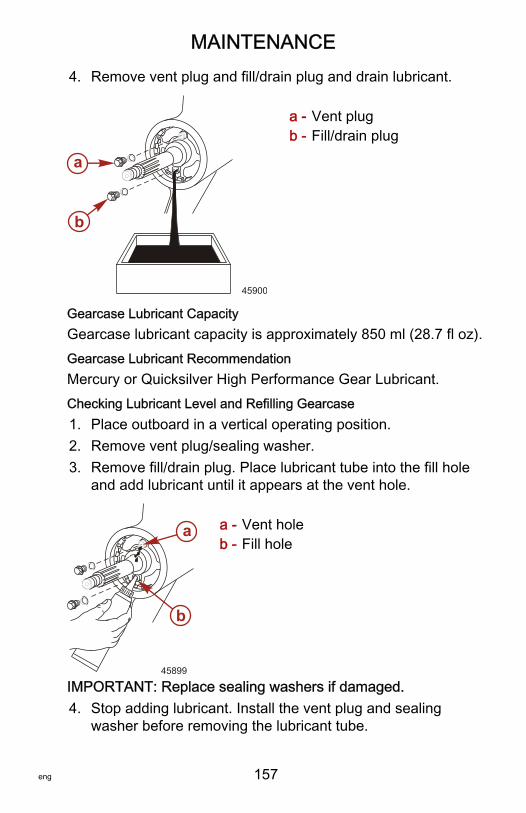
MAINTENANCE
eng 157
4. Remove vent plug and fill/drain plug and drain lubricant.
a - Vent plugb - Fill/drain plug
Gearcase Lubricant CapacityGearcase lubricant capacity is approximately 850 ml (28.7 fl oz).Gearcase Lubricant RecommendationMercury or Quicksilver High Performance Gear Lubricant.Checking Lubricant Level and Refilling Gearcase1. Place outboard in a vertical operating position.2. Remove vent plug/sealing washer.3. Remove fill/drain plug. Place lubricant tube into the fill hole
and add lubricant until it appears at the vent hole.
a - Vent holeb - Fill hole
IMPORTANT: Replace sealing washers if damaged.4. Stop adding lubricant. Install the vent plug and sealing
washer before removing the lubricant tube.
a
b
45900
a
b
45899

MAINTENANCE
158 eng
5. Remove lubricant tube and reinstall cleaned fill/drain plugand sealing washer.
STORAGE
eng 159
Storage PreparationThe major consideration in preparing your outboard for storage isto protect it from rust, corrosion, and damage caused by freezingof trapped water.The following storage procedures should be followed to prepareyour outboard for out of season storage or prolonged storage(two months or longer).
NOTICEWithout sufficient cooling water, the engine, the water pump,and other components will overheat and suffer damage.Provide a sufficient supply of water to the water inlets duringoperation.
FUEL SYSTEMIMPORTANT: Gasoline containing alcohol (ethanol or methanol)can cause a formation of acid during storage and can damagethe fuel system. If the gasoline being used contains alcohol, it isadvisable to drain as much of the remaining gasoline as possiblefrom the fuel tank, remote fuel line, and engine fuel system.IMPORTANT: This outboard is equipped with a closed fuelsystem when the engine is not running. With this closed system,fuel within the engine's fuel system, other than the fuel tank, willremain stable during normal storage periods without the additionof fuel treatment stabilizers.Fill the fuel tank and engine fuel system with treated (stabilized)fuel to help prevent formation of varnish and gum. Proceed withthe following instructions.• Portable fuel tank ‑ Pour the required amount of Fuel
System Treatment and Stabilizer (follow instructions oncontainer) into fuel tank. Tip fuel tank back and forth to mixstabilizer with the fuel.
• Permanently installed fuel tank ‑ Pour the required amountof Fuel System Treatment and Stabilizer (follow instructionson container) into a separate container and mix withapproximately one liter (one quart) of gasoline. Pour thismixture into fuel tank.
STORAGE
160 eng
TubeRef No. Description Where Used Part No.
124Fuel SystemTreatment andStabilizer
Fuel tank 92-8M0047932
Protecting External Outboard Components• Touch up any paint nicks. See your dealer for touch‑up
paint.• Spray Quicksilver or Mercury Precision Lubricants Corrosion
Guard on external metal surfaces (except corrosion controlanodes).
TubeRef No. Description Where Used Part No.
120CorrosionGuard External metal surfaces 92-802878 55
Protecting Internal Engine ComponentsIMPORTANT: Refer to Maintenance ‑ Spark Plug Inspection andReplacement for correct procedure for removing spark plugs.• Remove pencil coils and spark plugs.• Spray approximately 30 ml (1 fl oz) of Storage Seal Rust
Inhibitor into each spark plug hole.
TubeRef No. Description Where Used Part No.
119Storage SealRust Inhibitor Spark plug holes 92-858081K03
• Actuate key/push button start switch to crank the enginethrough one start cycle, which will distribute the storage sealthroughout the cylinders.
• Install spark plugs and pencil coils.
Gearcase• Drain and refill the gearcase lubricant (refer to Gearcase
Lubrication).
STORAGE
eng 161
Positioning Outboard for StorageStore outboard in an upright (vertical) position to allow water todrain out of the outboard.
NOTICEStoring the outboard in a tilted position can damage theoutboard. Water trapped in the cooling passages or rain watercollected in the propeller exhaust outlet in the gearcase canfreeze. Store the outboard in the full down position.
Battery Storage• Follow the battery manufacturer's instructions for storage
and recharging.• Remove the battery from the boat and check water level.
Recharge if necessary.• Store the battery in a cool, dry place.• Periodically check the water level and recharge the battery
during storage.
TROUBLESHOOTING
162 eng
Starter Motor Will Not Crank the EnginePOSSIBLE CAUSES• Lanyard stop switch not in "RUN" position.• Blown 5 amp fuse. Check DTS power harness circuit fuse.
Refer to Maintenance section.• Outboard is not shifted to neutral position.• Shift actuator failure. "Gear Shift Diff" error message shown
on System View. Refer to Maintenance section.• Weak battery or battery connections are loose or corroded.• Ignition key switch failure.• Wiring or electrical connection faulty.• Starter motor solenoid or slave solenoid failure.
Engine Will Not StartPOSSIBLE CAUSES• Incorrect starting procedure. Refer to Operation section.• Old or contaminated gasoline.• Fuel is not reaching the engine.
• Fuel tank is empty.• Fuel tank vent not open or restricted.• Fuel line is disconnected or kinked.• Fuel filter is obstructed. Refer to Maintenance section.• Fuel pump failure.• Fuel tank filter obstructed.
• Ignition system component failure.• Spark plugs fouled or defective. Refer to Maintenance
section.
Engine Starts But Will Not Shift Into Gear• Shift actuator failure. "Gear Shift Diff" error message shown
on System View. Refer to Maintenance section.
TROUBLESHOOTING
eng 163
Engine Runs ErraticallyPOSSIBLE CAUSES• Overheating ‑ Warning horn not working.• Low oil pressure. Check oil level.• Spark plugs fouled or defective. Refer to Maintenance
section.• Incorrect setup and adjustments.• Fuel is being restricted to the engine.
a. Engine fuel filter is obstructed. Refer to Maintenancesection.
b. Fuel tank filter obstructed.c. Stuck anti‑siphon valve located on permanently built‑in
type fuel tanks.d. Fuel line is kinked or pinched.
• Fuel pump failure.• Ignition system component failure.
Performance LossPOSSIBLE CAUSES• Overheating ‑ Warning horn not working.• Low oil pressure. Check oil level.• Throttle not opening fully.• Damaged propeller or improper propeller size.• Incorrect engine timing, adjustment, or setup.• Boat overloaded or load improperly distributed.• Excessive water in bilge.• Boat bottom is dirty or damaged.
Battery Will Not Hold ChargePOSSIBLE CAUSES• Battery connections are loose or corroded.• Low electrolyte level in battery.• Worn out or inefficient battery.

TROUBLESHOOTING
164 eng
• Excessive use of electrical accessories.• Defective rectifier, alternator, or voltage regulator.• Open circuit in the alternator output wire (fused link).
OWNER SERVICE ASSISTANCE
eng 165
Local Repair ServiceAlways return your outboard to your local authorized dealershould the need for service arise. Only he has the factory trainedmechanics, knowledge, special tools, equipment, and genuineparts and accessories to properly service your engine should theneed occur. He knows your engine best.
Service Away from HomeIf you are away from your local dealer and the need arises forservice, contact the nearest authorized dealer. Refer to theYellow Pages of the telephone directory. If, for any reason, youcannot obtain service, contact the nearest Mercury MarineService Office.
Parts and Accessories InquiriesAll inquiries concerning genuine replacement parts andaccessories should be directed to your local authorized dealer.The dealer has the necessary information to order parts andaccessories for you. When inquiring on parts and accessories,the dealer requires the model and serial number to order thecorrect parts.
Service AssistanceLOCAL REPAIR SERVICEIf you need service for your Mercury‑outboard‑powered boat,take it to your authorized dealer. Only authorized dealersspecialize in Mercury products and have factory‑trainedmechanics, special tools and equipment, and genuineQuicksilver parts and accessories to properly service yourengine.NOTE: Quicksilver parts and accessories are engineered andbuilt by Mercury Marine specifically for your power package.
OWNER SERVICE ASSISTANCE
166 eng
SERVICE AWAY FROM HOMEIf you are away from your local dealer and the need arises forservice, contact the nearest authorized dealer. If, for any reason,you cannot obtain service, contact the nearest Regional ServiceCenter. Outside the United States and Canada, contact thenearest Marine Power International Service Center.
STOLEN POWER PACKAGEIf your power package is stolen, immediately advise the localauthorities and Mercury Marine of the model and serial numbersand to whom the recovery is to be reported. This information ismaintained in a database at Mercury Marine to aid authoritiesand dealers in the recovery of stolen power packages.
ATTENTION REQUIRED AFTER SUBMERSION1. Before recovery, contact an authorized Mercury dealer.2. After recovery, immediate service by an authorized Mercury
dealer is required to reduce the possibility of serious enginedamage.
REPLACEMENT SERVICE PARTS
! WARNINGAvoid fire or explosion hazard. Electrical, ignition, and fuelsystem components on Mercury Marine products comply withfederal and international standards to minimize risk of fire orexplosion. Do not use replacement electrical or fuel systemcomponents that do not comply with these standards. Whenservicing the electrical and fuel systems, properly install andtighten all components.
Marine engines are expected to operate at or near full throttle formost of their lives. They are also expected to operate in bothfresh and saltwater environments. These conditions requirenumerous special parts.
OWNER SERVICE ASSISTANCE
eng 167
PARTS AND ACCESSORIES INQUIRIESDirect any inquiries concerning Quicksilver replacement partsand accessories to your local authorized dealer. The dealer hasthe necessary information to order parts and accessories for youif they are not in stock. Only authorized dealers can purchasegenuine Quicksilver parts and accessories from the factory.Mercury Marine does not sell to unauthorized dealers or retailcustomers. When inquiring about parts and accessories, thedealer requires the engine model and serial numbers to orderthe correct parts.
RESOLVING A PROBLEMSatisfaction with your Mercury product is important to your dealerand to us. If you ever have a problem, question or concern aboutyour power package, contact your dealer or any authorizedMercury dealership. If you need additional assistance:1. Talk with the dealership's sales manager or service
manager. Contact the owner of the dealership if the salesmanager and service manager have been unable to resolvethe problem.
2. If your question, concern, or problem cannot be resolved byyour dealership, please contact the Mercury Marine ServiceOffice for assistance. Mercury Marine will work with you andyour dealership to resolve all problems.
The following information will be needed by the CustomerService:• Your name and address• Your daytime telephone number• The model and serial numbers of your power package• The name and address of your dealership• The nature of the problem
CONTACT INFORMATION FOR MERCURY MARINECUSTOMER SERVICEFor assistance, call, fax, or write to the geographic office in yourarea. Please include your daytime telephone number with mailand fax correspondence.
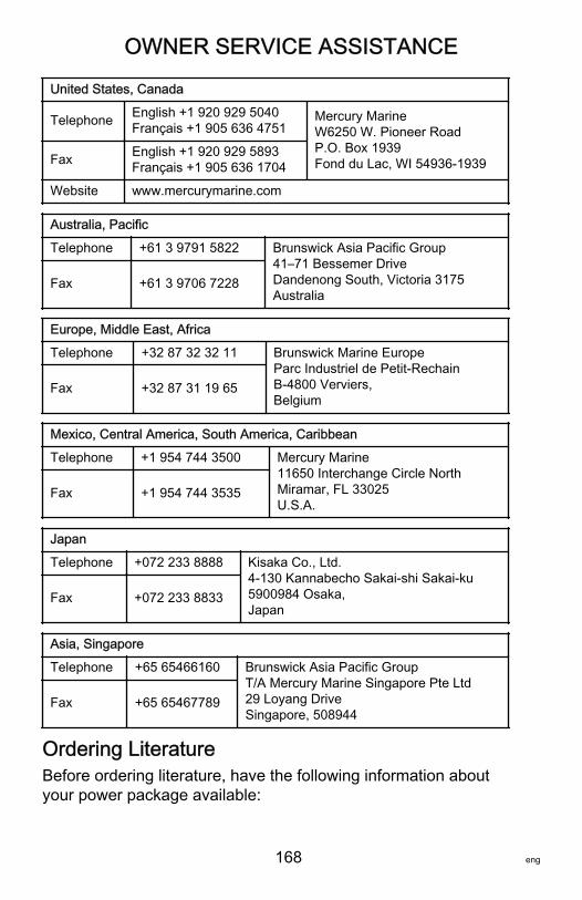
OWNER SERVICE ASSISTANCE
168 eng
United States, Canada
Telephone English +1 920 929 5040Français +1 905 636 4751
Mercury MarineW6250 W. Pioneer RoadP.O. Box 1939Fond du Lac, WI 54936-1939Fax English +1 920 929 5893
Français +1 905 636 1704
Website www.mercurymarine.com
Australia, Pacific
Telephone +61 3 9791 5822 Brunswick Asia Pacific Group41–71 Bessemer DriveDandenong South, Victoria 3175Australia
Fax +61 3 9706 7228
Europe, Middle East, Africa
Telephone +32 87 32 32 11 Brunswick Marine EuropeParc Industriel de Petit-RechainB-4800 Verviers,Belgium
Fax +32 87 31 19 65
Mexico, Central America, South America, Caribbean
Telephone +1 954 744 3500 Mercury Marine11650 Interchange Circle NorthMiramar, FL 33025U.S.A.
Fax +1 954 744 3535
Japan
Telephone +072 233 8888 Kisaka Co., Ltd.4-130 Kannabecho Sakai-shi Sakai-ku5900984 Osaka,Japan
Fax +072 233 8833
Asia, Singapore
Telephone +65 65466160 Brunswick Asia Pacific GroupT/A Mercury Marine Singapore Pte Ltd29 Loyang DriveSingapore, 508944
Fax +65 65467789
Ordering LiteratureBefore ordering literature, have the following information aboutyour power package available:
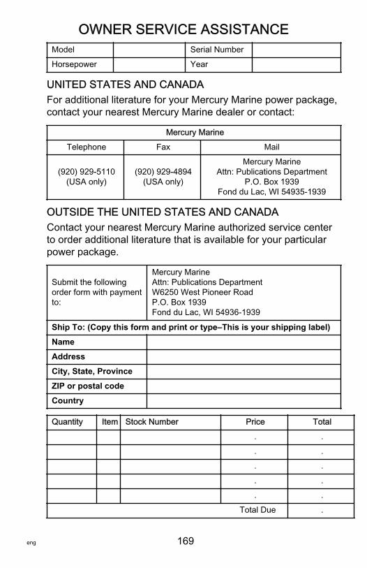
OWNER SERVICE ASSISTANCE
eng 169
Model Serial Number
Horsepower Year
UNITED STATES AND CANADAFor additional literature for your Mercury Marine power package,contact your nearest Mercury Marine dealer or contact:
Mercury Marine
Telephone Fax Mail
(920) 929‑5110(USA only)
(920) 929‑4894(USA only)
Mercury MarineAttn: Publications Department
P.O. Box 1939Fond du Lac, WI 54935-1939
OUTSIDE THE UNITED STATES AND CANADAContact your nearest Mercury Marine authorized service centerto order additional literature that is available for your particularpower package.
Submit the followingorder form with paymentto:
Mercury MarineAttn: Publications DepartmentW6250 West Pioneer RoadP.O. Box 1939Fond du Lac, WI 54936-1939
Ship To: (Copy this form and print or type–This is your shipping label)
Name
Address
City, State, Province
ZIP or postal code
Country
Quantity Item Stock Number Price Total
. .
. .
. .
. .
. .
Total Due .
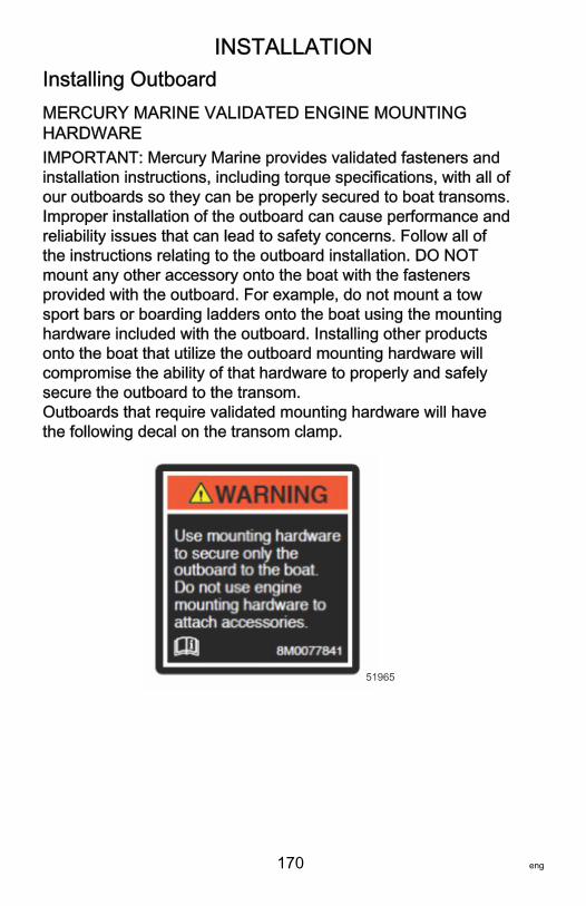
INSTALLATION
170 eng
Installing OutboardMERCURY MARINE VALIDATED ENGINE MOUNTINGHARDWAREIMPORTANT: Mercury Marine provides validated fasteners andinstallation instructions, including torque specifications, with all ofour outboards so they can be properly secured to boat transoms.Improper installation of the outboard can cause performance andreliability issues that can lead to safety concerns. Follow all ofthe instructions relating to the outboard installation. DO NOTmount any other accessory onto the boat with the fastenersprovided with the outboard. For example, do not mount a towsport bars or boarding ladders onto the boat using the mountinghardware included with the outboard. Installing other productsonto the boat that utilize the outboard mounting hardware willcompromise the ability of that hardware to properly and safelysecure the outboard to the transom.Outboards that require validated mounting hardware will havethe following decal on the transom clamp.
51965
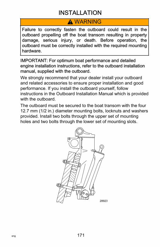
INSTALLATION
eng 171
! WARNINGFailure to correctly fasten the outboard could result in theoutboard propelling off the boat transom resulting in propertydamage, serious injury, or death. Before operation, theoutboard must be correctly installed with the required mountinghardware.
IMPORTANT: For optimum boat performance and detailedengine installation instructions, refer to the outboard installationmanual, supplied with the outboard.We strongly recommend that your dealer install your outboardand related accessories to ensure proper installation and goodperformance. If you install the outboard yourself, followinstructions in the Outboard Installation Manual which is providedwith the outboard.The outboard must be secured to the boat transom with the four12.7 mm (1/2 in.) diameter mounting bolts, locknuts and washersprovided. Install two bolts through the upper set of mountingholes and two bolts through the lower set of mounting slots.
28923
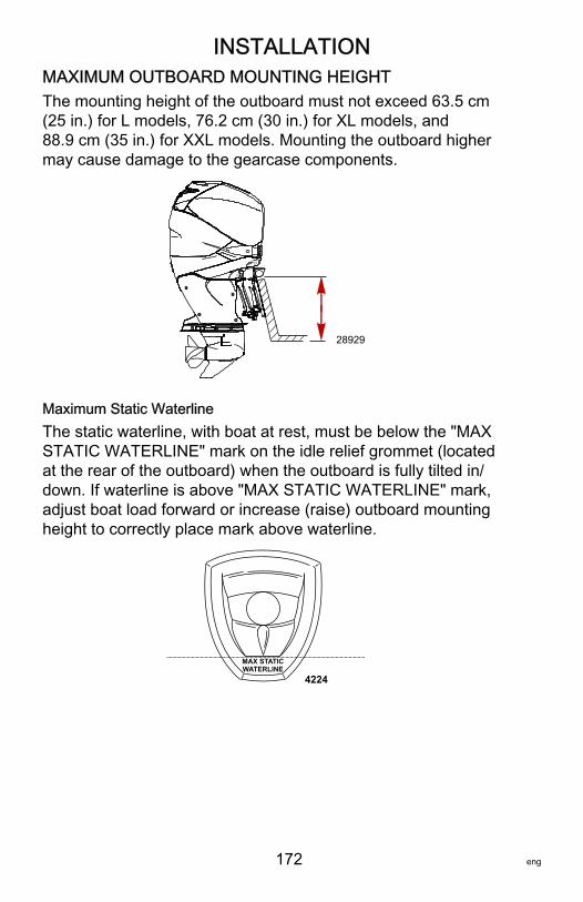
INSTALLATION
172 eng
MAXIMUM OUTBOARD MOUNTING HEIGHTThe mounting height of the outboard must not exceed 63.5 cm(25 in.) for L models, 76.2 cm (30 in.) for XL models, and88.9 cm (35 in.) for XXL models. Mounting the outboard highermay cause damage to the gearcase components.
28929
Maximum Static WaterlineThe static waterline, with boat at rest, must be below the "MAXSTATIC WATERLINE" mark on the idle relief grommet (locatedat the rear of the outboard) when the outboard is fully tilted in/down. If waterline is above "MAX STATIC WATERLINE" mark,adjust boat load forward or increase (raise) outboard mountingheight to correctly place mark above waterline.
MAX STATICWATERLINE
4224
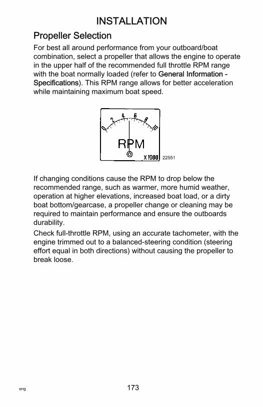
INSTALLATION
eng 173
Propeller SelectionFor best all around performance from your outboard/boatcombination, select a propeller that allows the engine to operatein the upper half of the recommended full throttle RPM rangewith the boat normally loaded (refer to General Information ‑Specifications). This RPM range allows for better accelerationwhile maintaining maximum boat speed.
22551
If changing conditions cause the RPM to drop below therecommended range, such as warmer, more humid weather,operation at higher elevations, increased boat load, or a dirtyboat bottom/gearcase, a propeller change or cleaning may berequired to maintain performance and ensure the outboardsdurability.Check full‑throttle RPM, using an accurate tachometer, with theengine trimmed out to a balanced‑steering condition (steeringeffort equal in both directions) without causing the propeller tobreak loose.
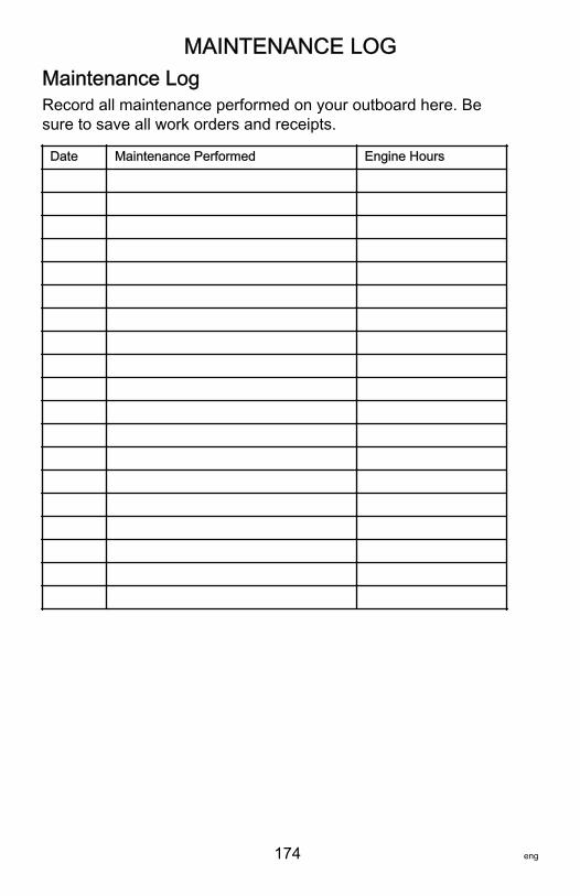
MAINTENANCE LOG
174 eng
Maintenance LogRecord all maintenance performed on your outboard here. Besure to save all work orders and receipts.
Date Maintenance Performed Engine Hours
Related Documents