Shielding and Reflecting Effectiveness of Carbon Fiber Reinforced Polymer (CFRP) Composites Javad Fouladgar #1 , Guillaume Wasselynck #1 , Didier Trichet #1 #1 IREENA Institut de Recherche en Energie Electrique de Nantes Atlantique 37 bd de l’université, 44600 Saint Nazaire, France 1 [email protected] Abstract—In this paper, the Shielding (SE) and Reflecting Effectiveness (RE) of a multilayer CFRP composites is studied. To avoid the costly composites, the low concentration carbon materials, far below the percolation threshold, are used. To maintain the current circulation which is indispensable for shielding, the fiber orientations are changed between two adjacent layers. The current circulation is then calculated through the capacities between the fibers. The finite elements method is used to solve a multilayer A-V formulation of Maxwell equations. The shielding and reflecting effectiveness of a thin composite sheet are then calculated for near fields of a square loop antenna. I. INTRODUCTION The shielding mechanisms of composite materials especially those with carbon nanotube have been largely studied by many authors interested in electromagnetic compatibility [1,2,3]. The Carbon Fiber Reinforced Polymer (CFRP) composites, used especially in aeronautic industry, could have also a good shielding and absorbing effectiveness while presenting high mechanical and chemical resistance per unit weight[4,5]. A CFRP is a pileup of several layers, as shown in Fig. 1(a). In each layer, the carbon fibers have the same direction and maintain together by a dielectric resin. However, the fibers direction should be different between adjacent layers in order to facilitate the current circulation between layers as shown in Fig. 1(b). Fig. 1(a). Stratified composite Fig. 1(b). Fibers orientation Fig.2 shows the schematization of the current circulation in a two layer composite excited by a square loop antenna parallel to the surface of the composite. On the current loops, the white parts correspond to paths with high conductivities and the black parts to those with weak conductivities, i.e. the conductivity transversal to the fibers. When the fibers of the two layers are in the same direction (UD composite), the currents are forced to follow long paths with weak conductivity to follow the square antenna. But in the 0-90 composite with orthogonal fibers in the successive layers, the currents go from one layer to the next thanks to the small layer thickness (136μm) relative to the antenna size. UD 0-90 (orthogonal) Fig. 2 Current circulation between the fibers and layers To obtain a relevant model for current circulation in composite materials, several difficulties have to be overcome due to the fact that composites are highly anisotropic and heterogeneous. The main difficulty is the important scale factor between fiber’s diameter (7 μm) and composite size. Furthermore, fibers are randomly positioned in the section of one layer. Due to the important scale factor, it is impossible to simulate directly the whole material. One should use then a homogenization technique in order to obtain the electrical conductivities tensor which is used then in a multi-layer electromagnetic model based on Finite Element Method (F.E.M). II. HOMOGENIZATION METHOD Fig.3 shows the fibers arrangement in a cross section of composite with several fibers orientation at a filling rate of 59%. From this figure, several information can be extracted: • The fibers are randomly distributed in the section; • The fibers are separated by a dielectric resin; • The fibers are not parallel to each other and contact between them may occur; • These contacts are randomly distributed and the number of contact depends of the filling rate. Fig. 3. Section of CFRPC. Copyright 2013 IEICE Proceedings of the "2013 International Symposium on Electromagnetic Theory" 21AM1F-03 104

Welcome message from author
This document is posted to help you gain knowledge. Please leave a comment to let me know what you think about it! Share it to your friends and learn new things together.
Transcript
Shielding and Reflecting Effectiveness of Carbon Fiber Reinforced Polymer (CFRP) Composites
Javad Fouladgar #1, Guillaume Wasselynck #1, Didier Trichet #1 #1 IREENA Institut de Recherche en Energie Electrique de Nantes Atlantique
37 bd de l’université, 44600 Saint Nazaire, France 1 [email protected]
Abstract—In this paper, the Shielding (SE) and Reflecting
Effectiveness (RE) of a multilayer CFRP composites is studied. To avoid the costly composites, the low concentration carbon materials, far below the percolation threshold, are used. To maintain the current circulation which is indispensable for shielding, the fiber orientations are changed between two adjacent layers. The current circulation is then calculated through the capacities between the fibers. The finite elements method is used to solve a multilayer A-V formulation of Maxwell equations. The shielding and reflecting effectiveness of a thin composite sheet are then calculated for near fields of a square loop antenna.
I. INTRODUCTION The shielding mechanisms of composite materials especially those with carbon nanotube have been largely studied by many authors interested in electromagnetic compatibility [1,2,3]. The Carbon Fiber Reinforced Polymer (CFRP) composites, used especially in aeronautic industry, could have also a good shielding and absorbing effectiveness while presenting high mechanical and chemical resistance per unit weight[4,5].
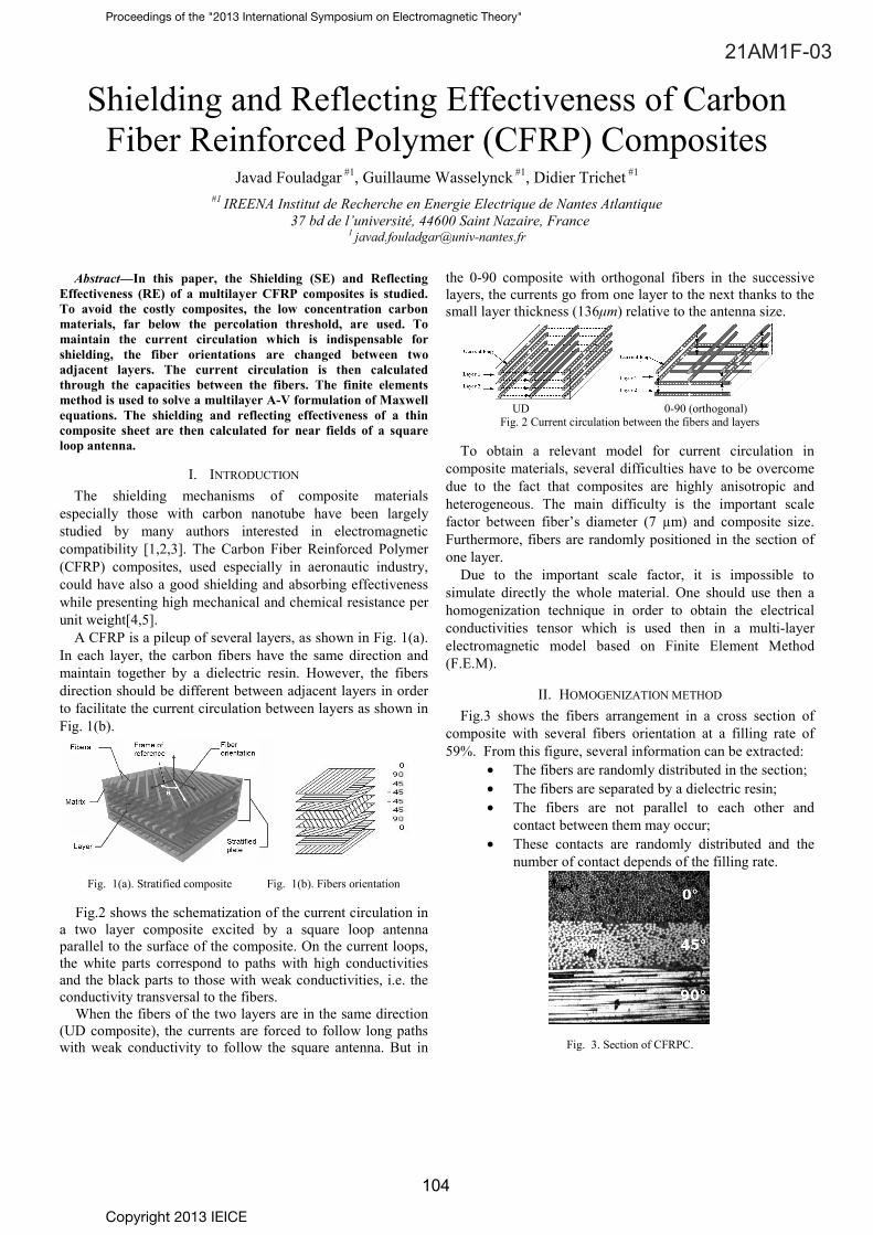
A CFRP is a pileup of several layers, as shown in Fig. 1(a). In each layer, the carbon fibers have the same direction and maintain together by a dielectric resin. However, the fibers direction should be different between adjacent layers in order to facilitate the current circulation between layers as shown in Fig. 1(b).
Fig. 1(a). Stratified composite Fig. 1(b). Fibers orientation
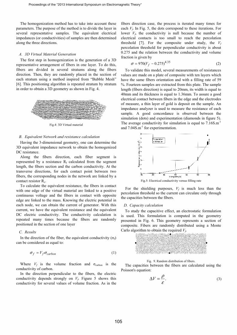
Fig.2 shows the schematization of the current circulation in
a two layer composite excited by a square loop antenna parallel to the surface of the composite. On the current loops, the white parts correspond to paths with high conductivities and the black parts to those with weak conductivities, i.e. the conductivity transversal to the fibers.
When the fibers of the two layers are in the same direction (UD composite), the currents are forced to follow long paths with weak conductivity to follow the square antenna. But in
the 0-90 composite with orthogonal fibers in the successive layers, the currents go from one layer to the next thanks to the small layer thickness (136μm) relative to the antenna size.
UD 0-90 (orthogonal)
Fig. 2 Current circulation between the fibers and layers
To obtain a relevant model for current circulation in composite materials, several difficulties have to be overcome due to the fact that composites are highly anisotropic and heterogeneous. The main difficulty is the important scale factor between fiber’s diameter (7 µm) and composite size. Furthermore, fibers are randomly positioned in the section of one layer.
Due to the important scale factor, it is impossible to simulate directly the whole material. One should use then a homogenization technique in order to obtain the electrical conductivities tensor which is used then in a multi-layer electromagnetic model based on Finite Element Method (F.E.M).
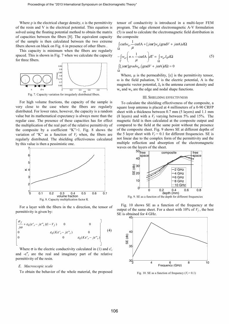
II. HOMOGENIZATION METHOD Fig.3 shows the fibers arrangement in a cross section of
composite with several fibers orientation at a filling rate of 59%. From this figure, several information can be extracted:
• The fibers are randomly distributed in the section; • The fibers are separated by a dielectric resin; • The fibers are not parallel to each other and
contact between them may occur; • These contacts are randomly distributed and the
number of contact depends of the filling rate.
Fig. 3. Section of CFRPC.
Copyright 2013 IEICE
Proceedings of the "2013 International Symposium on Electromagnetic Theory"
21AM1F-03
104
The homogenization method has to take into account these parameters. The purpose of the method is to divide the layer in several representative samples. The equivalent electrical impedances (or conductivities) of samples are then determined along the three directions.
A. 3D Virtual Material Generation The first step in homogenization is the generation of a 3D
representative arrangement of fibers in one layer. To do this, fibers are divided in several stratums along the fibers direction. Then, they are randomly placed in the section of each stratum using a method inspired from “Bubble Mesh” [6]. This positioning algorithm is repeated stratum by stratum in order to obtain a 3D geometry as shown in Fig. 4.
Fig.4: 3D Virtual material
B. Equivalent Network and resistance calculation Having the 3-dimensional geometry, one can determine the
3D equivalent impedance network to obtain the homogenized DC resistance.
Along the fibers direction, each fiber segment is represented by a resistance Rf calculated from the segment length, the fibers section and the carbon conductivity. At the transverse directions, for each contact point between two fibers, the corresponding nodes in the network are linked by a contact resistor Rc.
To calculate the equivalent resistance, the fibers in contact with one edge of the virtual material are linked to a positive continuous voltage and the fibers in contact with opposite edge are linked to the mass. Knowing the electric potential in each node, we can obtain the current of generator. With this current, we have the equivalent resistance and the equivalent DC electric conductivity. The conductivity calculation is repeated many times because the fibers are randomly positioned in the section of one layer
C. Results In the direction of the fiber, the equivalent conductivity (σf)
can be considered as equal to:
f f carbonVσ σ= (1)
Where Vf is the volume fraction and σcarbon is the
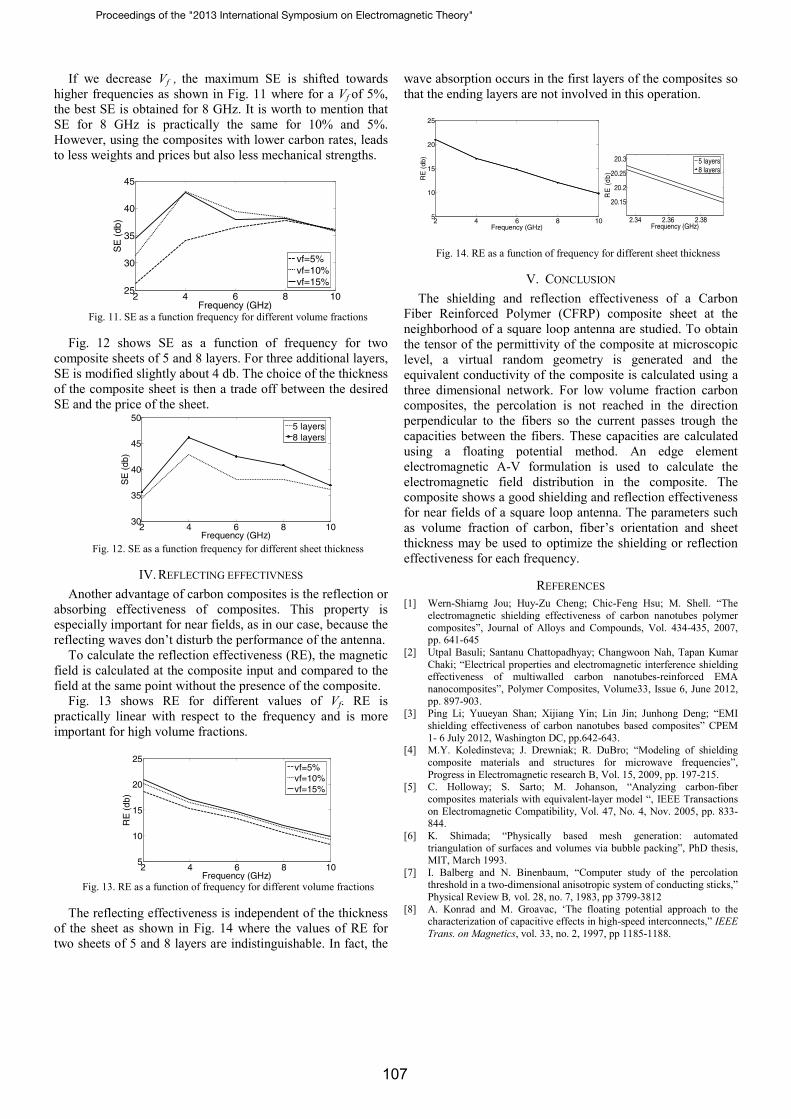
conductivity of carbon. In the direction perpendicular to the fibers, the electric
conductivity depends strongly on Vf. Figure 5 shows this conductivity for several values of volume fraction. As in the
fibers direction case, the process is iterated many times for each Vf. In Fig. 5, the dots correspond to these iterations. For lower Vf, the conductivity is null because the number of electrical contacts is too small to reach the percolation threshold [7]. For the composite under study, the Vf percolation threshold for perpendicular conductivity is about 0.275 and the relation between the conductivity and volume fraction is given by 4.35970( 0.275)fVσ = − (2)
To validate this model, several measurements of resistances values are made on a plate of composite with ten layers which have the same fibers orientation and with a filling rate of 59 %. Fourteen samples are extracted from this plate. The sample length (fibers direction) is equal to 20mm, its width is equal to 40mm and its thickness is equal to 1.36mm. To assure a good electrical contact between fibers in the edge and the electrodes of measure, a thin layer of gold is deposit on the sample. An impedance analyzer is used to measure the resistance of each sample. A good concordance is observed between the simulation (dots) and experimentation (diamonds in figure 5). The average conductivity for simulation is equal to 7.16S.m-1 and 7.04S.m-1 for experimentation.
Fig.5: Electrical conductivity versus filling rate
For the shielding purposes, Vf is much less than the
percolation threshold so the current can circulate only through the capacities between the fibers.
D. Capacity calculation To study the capacitive effect, an electrostatic formulation
is used. This formulation is computed in the geometry presented in Fig. 6. This geometry represents a section of composite. Fibers are randomly distributed using a Monte Carlo algorithm to obtain the required Vf.
Fig. 9. Random distribution of fibers. The capacities between the fibers are calculated using the
Poisson's equation:
.ερ=ΔV (3)
Proceedings of the "2013 International Symposium on Electromagnetic Theory"
105
Where ρ is the electrical charge density, ε is the permittivity of the resin and V is the electrical potential. This equation is solved using the floating potential method to obtain the matrix of capacities between the fibers [8]. The equivalent capacity of the sample is then calculated between the two extreme fibers shown on black on Fig. 6 in presence of other fibers .
This capacity is minimum when the fibers are regularly spaced. This is shown in Fig. 7 when we calculate the capacity for three fibers.
0 0.2 0.4 0.6 0.8 1
0.65
0.7
0.75
0.8
0.85
0.9
0.95
x/d
C/C
max
Fig. 7. Capacity variation for irregularly distributed fibers.
For high volume fractions, the capacity of the sample is
very close to the case where the fibers are regularly distributed. For lower rates, however, the capacity is a random value but its mathematical expectancy is always more than the regular case. The presence of these capacities has for effect the multiplication of the real part of the relative permittivity of the composite by a coefficient “K”>1. Fig. 8 shows the variation of “K” as a function of Vf when, the fibers are regularly distributed. The shielding effectiveness calculated by this value is then a pessimistic one.
0 0.1 0.2 0.3 0.4 0.5 0.6 0.71
2
3
4
5
6
7
volume fraction
K
Fig. 8. Capacity multiplication factor K
. For a layer with the fibers in the x direction, the tensor of
permittivity is given by:
0
0
0
( ' " )(1 ) 0 0
0 ( ' " ) 00 0 ( ' " )
fr r f
r r
r r
j Vj
K jK j
σε ε ε
ωε ε ε
ε ε ε
⎡ ⎤+ − −⎢ ⎥
⎢ ⎥⎢ ⎥−⎢ ⎥
−⎢ ⎥⎢ ⎥⎣ ⎦
(4)
Where σ is the electric conductivity calculated in (1) and ε'r and -ε″r are the real and imaginary part of the relative permittivity of the resin.
E. Macroscopic scale To obtain the behavior of the whole material, the proposed
tensor of conductivity is introduced in a multi-layer FEM program. The edge element electromagnetic A-V formulation (5) is used to calculate the electromagnetic field distribution in the composite
( )
0
1curl . curlA [ ] (grad A)
1. curlA
[ ] . grad A 0
a a
a a
n
w j w V j d
w n d w J d
j gradw V j d
ωε ωμ
μωε ω
Ω
Γ Ω
Ω
+ + Ω
⎛ ⎞− ∧ Γ = Ω⎜ ⎟⎜ ⎟
⎝ ⎠+ Ω =
∫
∫ ∫
∫
(5)
Where, μ is the permeability, [ε] is the permittivity tensor, ω is the field pulsation, V is the electric potential, A is the magnetic vector potential, J0 is the antenna current density and wa and wn are the edge and nodal shape functions.
III. SHIELDING EFFECTIVNESS To calculate the shielding effectiveness of the composite, a
square loop antenna is placed at 4 millimeters of a 0-90 CRFP sheet with a thickness between 0.7 mm (5 layers) and 1.1 mm (8 layers) and with a Vf varying between 5% and 15%. The magnetic field is then calculated at the composite output and compared to the field at the same point without the presence of the composite sheet. Fig. 9 shows SE at different depths of the 5 layer sheet with Vf = 0.1 for different frequencies. SE is not linear due to the complex form of the permittivity and the multiple reflection and absorption of the electromagnetic waves on the layers of the sheet.
0 0.2 0.4 0.6 0.80
10
20
30
40
50freespace
composite freespace
depth (mm)
SE
(db
)
2 GHz4 GHz6 GHz8 GHz10 GHz
Fig. 9. SE as a function of the depth for different frequencies
Fig. 10 shows SE as a function of the frequency at the
output of the same sheet. For a sheet with 10% of Vf , the best SE is obtained for 4 GHz.
2 4 6 8 1030
35
40
45
Frequency (GHz)
SE
(db
)
Fig. 10. SE as a function of frequency (Vf = 0.1)
x d-x
Proceedings of the "2013 International Symposium on Electromagnetic Theory"
106
If we decrease Vf , the maximum SE is shifted towards higher frequencies as shown in Fig. 11 where for a Vf of 5%, the best SE is obtained for 8 GHz. It is worth to mention that SE for 8 GHz is practically the same for 10% and 5%. However, using the composites with lower carbon rates, leads to less weights and prices but also less mechanical strengths.
2 4 6 8 1025
30
35
40
45
Frequency (GHz)
SE
(db
)
vf=5%vf=10%vf=15%
Fig. 11. SE as a function frequency for different volume fractions
Fig. 12 shows SE as a function of frequency for two
composite sheets of 5 and 8 layers. For three additional layers, SE is modified slightly about 4 db. The choice of the thickness of the composite sheet is then a trade off between the desired SE and the price of the sheet.
2 4 6 8 1030
35
40
45
50
Frequency (GHz)
SE
(db
)
5 layers8 layers
Fig. 12. SE as a function frequency for different sheet thickness
IV. REFLECTING EFFECTIVNESS Another advantage of carbon composites is the reflection or
absorbing effectiveness of composites. This property is especially important for near fields, as in our case, because the reflecting waves don’t disturb the performance of the antenna.
To calculate the reflection effectiveness (RE), the magnetic field is calculated at the composite input and compared to the field at the same point without the presence of the composite.
Fig. 13 shows RE for different values of Vf. RE is practically linear with respect to the frequency and is more important for high volume fractions.
2 4 6 8 105
10
15
20
25
Frequency (GHz)
RE
(db
)
vf=5%vf=10%vf=15%
Fig. 13. RE as a function of frequency for different volume fractions
The reflecting effectiveness is independent of the thickness
of the sheet as shown in Fig. 14 where the values of RE for two sheets of 5 and 8 layers are indistinguishable. In fact, the
wave absorption occurs in the first layers of the composites so that the ending layers are not involved in this operation.
2 4 6 8 105
10
15
20
25
Frequency (GHz)
RE
(db
)
2.34 2.36 2.38
20.15
20.2
20.25
20.3
Frequency (GHz)
RE
(db
)
5 layers8 layers
Fig. 14. RE as a function of frequency for different sheet thickness
V. CONCLUSION The shielding and reflection effectiveness of a Carbon
Fiber Reinforced Polymer (CFRP) composite sheet at the neighborhood of a square loop antenna are studied. To obtain the tensor of the permittivity of the composite at microscopic level, a virtual random geometry is generated and the equivalent conductivity of the composite is calculated using a three dimensional network. For low volume fraction carbon composites, the percolation is not reached in the direction perpendicular to the fibers so the current passes trough the capacities between the fibers. These capacities are calculated using a floating potential method. An edge element electromagnetic A-V formulation is used to calculate the electromagnetic field distribution in the composite. The composite shows a good shielding and reflection effectiveness for near fields of a square loop antenna. The parameters such as volume fraction of carbon, fiber’s orientation and sheet thickness may be used to optimize the shielding or reflection effectiveness for each frequency.
REFERENCES [1] Wern-Shiarng Jou; Huy-Zu Cheng; Chic-Feng Hsu; M. Shell. “The
electromagnetic shielding effectiveness of carbon nanotubes polymer composites”, Journal of Alloys and Compounds, Vol. 434-435, 2007, pp. 641-645
[2] Utpal Basuli; Santanu Chattopadhyay; Changwoon Nah, Tapan Kumar Chaki; “Electrical properties and electromagnetic interference shielding effectiveness of multiwalled carbon nanotubes-reinforced EMA nanocomposites”, Polymer Composites, Volume33, Issue 6, June 2012, pp. 897-903.
[3] Ping Li; Yuueyan Shan; Xijiang Yin; Lin Jin; Junhong Deng; “EMI shielding effectiveness of carbon nanotubes based composites” CPEM 1- 6 July 2012, Washington DC, pp.642-643.
[4] M.Y. Koledinsteva; J. Drewniak; R. DuBro; “Modeling of shielding composite materials and structures for microwave frequencies”, Progress in Electromagnetic research B, Vol. 15, 2009, pp. 197-215.
[5] C. Holloway; S. Sarto; M. Johanson, “Analyzing carbon-fiber composites materials with equivalent-layer model “, IEEE Transactions on Electromagnetic Compatibility, Vol. 47, No. 4, Nov. 2005, pp. 833-844.
[6] K. Shimada; “Physically based mesh generation: automated triangulation of surfaces and volumes via bubble packing”, PhD thesis, MIT, March 1993.
[7] I. Balberg and N. Binenbaum, “Computer study of the percolation threshold in a two-dimensional anisotropic system of conducting sticks,” Physical Review B, vol. 28, no. 7, 1983, pp 3799-3812
[8] A. Konrad and M. Groavac, ‘The floating potential approach to the characterization of capacitive effects in high-speed interconnects,” IEEE Trans. on Magnetics, vol. 33, no. 2, 1997, pp 1185-1188.
Proceedings of the "2013 International Symposium on Electromagnetic Theory"
107
Related Documents