Welcome message from author
This document is posted to help you gain knowledge. Please leave a comment to let me know what you think about it! Share it to your friends and learn new things together.
Transcript

IPPJ-T-38
PROCEEDINGSOF
THE JAPAN-U.S. WORKSHOP P-118ON
VACUUM TECHNOLOGIES FOR FUSION DEVICESAugust 1-5,1988
Edited by
A. MIYAHARA
Institute of Plasma Physics, Nagoya UniversityChikusa-ku, Nagoya 464-01, Japan
TABLE OF CONTENTS
OPENING ADDRESS, A. Miyahara 1
EXECUTIVE SUMMARY
Executive Summary 7
List of Participants 13
Program 14
PLENARY SESSION
1. Overview of Vacuum-Related R&D Efforts in U.S., J. R. Haines ... 21
2. Assessment of the Vacuum and Gas Handling Systems for the TFTR
Project, H. F. Dylla 23
3. Vacuum Technological Experiences of JT-60 Operation, M. Shimizu . . 36
4. Design of CIT Vacuum Pumping System, J. K. Jones 57
5. Conceptual Design of a Closed Vacuum Pumping System Using
Turbomolecular Pump for Fusion Reactor, K. Akaishi 66
6. Tritium Consumption and Tritium Inventory in TFTR and CIT,
H. F. Dylla 73
7. Complete Fuel Processing Loop Operation at the Tritium Systems
Test Assembly with 100 Grams-Level Tritium, S. Hirata 87
8. Outline of the Tritium Process Laboratory at JAERI, T. Konishi . . 95
9. Submitting to International Symposium on Fusion Nuclear
Technology, K. Watanabe 107
10. Outgassing Mechanisms from the Surface and the Bulk, G. Horikoshi .117
11. ITER Vacuum Pumping System. J. R. Haines 124
12. Outgassing of Hydrogen from Metal Wall, M. Yamawaki 132
TOPICS ORIENTED SESSION
PUMPING
1. Development of Ceramic Turbomolecular Pumping System for Fusion
Reactors, Y. Murakami 145
2. Performance Test of Ceramic Rotor Turbomolecular Pumps, T. Abe. . 153
3. Industrial Experience with Magnetic Bearing Turbomolecular Pumps,
J. K. Jones 165
GAUGING
4. New Helium Detection System "A-U Gauge", K. Akaishi 174
5. Compatibility of Spinning Rotor Gauge with Tritium Handling
System, K. Watanabe 182
REMOTE MAINTENANCE
B. TFTR In-Vessel Maintenance, H. F. Dylla 191
7. CIT In-Vessel Remote Maintenance, R. Gallix 206
8. Experience with In-Vacuum Remote Manipulators for Fusion Research,
Y. Murakami 218
9. Design and Testing of a Manipulator Arm Used in High Vacuum,
M. Kondo 227
FIRST WALL. PUMP LIMITER, DIVERTOR
10. Pump Limiter Analysis in Vacuum Physics Viewpoints, T. Kawamura . 235
11. Calculation of Duct Conductance for Energetic Gases by Monte-Carlo
Method, K. Nakamura 240
12. CIT Vacuum Vessel, First Wall and Divertor Conceptual Design,
R. Gallix 247
13. ITER First Wall, Divertor, and Vacuum Vessel, J. R. Haines ... 276
14. Low Activation Al-Alloy Vacuum Vessel with Honeycomb Structure,
H. Ishimaru, H. Takemura and A. Miyahara 288
OTHER TOPICS
15. Particle Balance of Thermal Neutrals in an Ultrahigh Vacuum System
Measured by the Conductance Modulation Method, K. Terada, T. Okano
and Y. Tuzi 295
16. Design and Operation of Pellet Injector, T. Uchikawa 299
17. Plasma Driven Permeation of Hydrogen Isotopes,
Y. Fujii and M. Okamoto 307
Opening Address
Akira Miyahara
Institute of Plasma Physics, Nagoya University
Nagoya 464-01, Japan
It is not necessary to re-emphasize the importance of vacuum
technologies in fusion research as it has been recognized since the
beginning of the fusion work. However, fusion community does not seem
to appreciate it to the same extent as the accelerator community does.
This is so because in case of accelerators, specially storage ring
systems the requirement namely attainment of ultra high vacuum in order
to avoid collisional losses is well defined. On the other hand, it is
not possible to define the requirements so precisely in case of fusion
devices. One of the reasons being that the core plasma interacts with
vessel wall so strongly and unpredictably that it becomes difficult to
identify the role played by the individual components. Consequently
plasma physicists have so far generally asked for reliable vacuum
components to ensure greater availability of the machine. However, in
the next step and the next generation machines like CIT, LHS, ITER, FER
and NET, vacuum technologies would play a more significant role because
CIT will introduce tritium in vacuum vessel and the aim of ITER project
is to demonstrate particle balance, namely to achieve steady state
operation with D-T fuels.
I hope, during this workshop, we may discuss frankly the problems
we have met and identify the anticipated problems to be solved in
future.
-1-
Copies of Presented Transparencies
Importance of vacuum technologies is well recognizedfrom the beginning of the fusion research.
1. Pump down: To start operation of the devices.
2. Baking and discharge cleaning: To reduce oxygen,contamination.
3. Gettering: To control the neutral particles.
4. Leak detection, Gauging and so on: To achieve betteravailability of the device operation.
Recent plasma physics experiments asked us to developadvanced vacuum science and technologies.
1. Unloading of plasma particles such as fuels, ashes andimpurities by divertors and pump limiters.
2. Interpretation of dynamic retentions such as super shot,wall pumping and so on.
3. Special coating technique for example boronization toclarify edge core correlation plasma physics.
New era of fusion research will come very soon throughintroduction of D-T fuels into tokamaks like TFTR, JET and CIT.New vacuum technologies are needed.
1. What kind of procedure is necessary to perform powerfuldischarge in tokamaks?
2. How about the influence of 14 MeV neutron environment?
3. It is necessary to identity the specific requirements oftritium compatible vacuum system.
-2-
The mission of the next generation machines like ITER,
FER, NET and T-20 is to demonstrate steady state operation,
namely, particle balance of the fusion devices.
It means, unloading of fuel particles, compression or
condensation.of unloaded particles, purification of fuels,
preparation for refueling and fueling by pellet injector.
Almost all items closely relate to vacuum technology.
Usually fusion research and development are too much
project oriented.
In order to design realistic fusion reactor, it is
necessary to introduce innovative idea more and more.
Communications to research group other than fusion is needed.
Encourage to deepen and broaden the basic knowledge of vacuum
science under the well defined fusion reactor design problem •
are quite important in future.
Many items will be presented during the workshop. I
j hope you can identify the status of the key research for long
pulse hydrogen device like LHS, ignition machine like CIT and
experimental reactor like ITER, and list up the problems to be
solved and discussed in the next workshop.
-3-

EXECUTIVE SUMMARY
Executive Summary of Workshop P-118
on Vacuum Technologies for Fusion Devices
1. Introduction
The Japan-U.S . Workshop P-118 on "Vacuum Technologies for Fusion
Devices" was held a t the I n s t i t u t e of Plasma Physics , Nagoya Universi ty
on August 1-5, 1988. Altogether 33 pa r t i c ipan t s including 4 pa r t i c ipan t s
from the U.S. attended the workshop. The l i s t of pa r t i c i pan t s is attached
in Appendix I of th is summary.
I t i s commonly recognized that one of the major obstacles to achieving
high a v a i l a b i l i t y of present day large devices i s the vacuum system, but
i t has not been sys temat ica l ly discussed so f a r . Moreover, in t roduct ion
of t r i t i u m in to the vesse l of DT burning machines wi l l have impact on
design of vacuum system. In tegra t ion of the vacuum pumping system into
the o v e r a l l design of an ITER l i k e machine i s e s s e n t i a l for achieving
s t e a d y - s t a t e fue l cycle o p e r a t i o n s . I t i s e s p e c i a l l y impor t an t to
care fu l ly evaluate the vacuum system requirements for t h i s type of device
in o r d e r to e n s u r e adequa te per formance wi th minimum c o s t . These
considera t ions provided the motivations to hold the workshop. Final ly we
intend to examine if the s t a t e of a r t of the bas ic vacuum sc ience and
technology is advanced enough to allow c r i t i c a l discussion on performance
and budget for vacuum systems of large fusion devices.
2. Workshop Procedure
The workshop l a s t e d for four days . The f i r s t day was devoted to
plenary ta lk to define the problem area , p resen ta t ions of present s ta tus
of the machines and so on. The second day was dedicated to the topics
o r i en ted p r e s e n t a t i o n s . On the t h i r d day, the US p a r t i c i p a n t s v i s i t e d
Mitsubishi Heavy I n d u s t r i e s , Hiroshima Works, for de t a i l ed diuscussions
on ceramic turbomolecular pumps under development. Drs. Y. Murakami and
T. Abe guided the t o u r . On t h i r d day. Japanese p a r t i c i p a n t s prepared
-I-
summary of the workshop. The fourth day was se t for summary discussion.
The t ab l e s 1-3 which conta in the r e s u l t s of d iscuss ions on th i s day are
appended to th i s executive summary. The complete program of the workshop
is given in Appendix I I .
A workshop document which included each p resen ta t ion and an abs t r ac t
or extended abstract was compiled.
3. Cr i t ica l Issues
During the workshop, in tens ive d iscuss ions were held. Foliowings are
the c r i t i c a l issues to be solved in near future .
1) Actual performance data on the vacuum opera t ion of e x i s t i n g fusion
devices ( i . e . pumping speeds , leak r a t e s , ou tgass ing r a t e s , e t c . ) ,
inc luding comparisons of achieved r e s u l t s vs . s p e c i f i c a t i o n s will be
valuable in the spec i f i ca t i on and design of the vacuum pumping system
and vacuum components for the next generat ion of fusion devices (CIT,
LHS, FER. ITER).
2) Accurate performance da ta on e x i s t i n g dev ices demands c a l i b r a t e d
measurements of p r e s s u r e , p a r t i a l p r e s s u r e and pumping speed. The
cont inued development of vacuum s t a n d a r d s , c a l i b r a t i o n methods for
to t a l pressure and p a r t i a l pressure measurements should be encouraged.
In addi t ion , the development of new gauges compatible with the fusion
( e l e c t r o m a g n e t i c and r a d i a t i o n ) environment should be promoted.
Organized a c t i v i t i e s in basic science and technology with well defined
problems are needed to establ ish r igid and precise data base.
3) The next generat ion of fusion devices wi l l r equ i re t r i t i um compatible
vacuum pumping systems tha t should be optimized for the pumping of D-T
and helium and allow for e f f i c i e n t downstream separa t ion of hydrogen
i so topes , helium ash, and impurity gases . The ceramic turbomolecular
pumping system under development a t JAERI/Mitsubishi i s a pa r t i cu l a r ly
promising cand ida te . Other pumping op t ions such as "dry" mechanical
pumps, compound cryopumps and ge t te r pumps should also be pursued.
- 8 -
4) We do n o t s e e t h e n e e d f o r d e v e l o p m e n t of h e a v y d u t y , i n - v a c u u m
m a n i p u l a t o r s . H o w e v e r , d e v e l o p m e n t of s p e c i a l p u r p o s e , l i g h t d u t y
m a n i p u l a t o r s f o r a c t i v i t i e s s u c h a s l e a k d e t e c t i o n and i n - v e s s e l
c o m p o n e n t i n s p e c t i o n a r e h i g h l y d e s i r a b l e . M a i n t e n a n c e o p e r a t i o n s
c a r r i e d o u t u s i n g o i l l u b r i c a t e d m a n i p u l a t o r s in a c o n t r o l l e d , i n e r t
g a s e n v i r o n m e n t i s l i k e l y t o be an a c c e p t a b l e a p p r o a c h f o r f u t u r e
f u s i o n e x p e r i m e n t s w h i c h i n c o r p o r a t e w i t h s t a t e - o f - t h e - a r t w a l l
c o n d i t i o n i n g t e c h n i q u e s s u c h a s h i g h t e m p e r a t u r e b a k i n g and d i s c h a r g e
c l e a n i n g ( ~ 3 5 0 t ) .
5) To r e d u c e u n c e r t a i n t i e s in t h e d e s i g n of l a r g e , c o s t l y m a c h i n e s l i k e
CIT a n d I T E R , x n - t o k a m a k e n g i n e e r i n g t e s t s of p l a s m a / m a t e r i a l
i n t e r a c t i o n phenomena a r e needed t o v e r i f y a s s u m p t i o n s beyond t h e range
of l a b o r a t o r y e x p e r i m e n t s .
6) I n t e n s e U S - J a p a n c o l l a b o r a t i o n s i n c l u d i n g u t i l i z a t i o n
of s m a l l t e s t f a c i l i t i e s , e x c h a n g e of i n f o r m a t i o n on i n - t o k a m a k t e s t
r e s u l t s of key c o m p o n e n t s a r e n e c e s s a r y . C o o p e r a t i o n among f u s i o n
s c i e n t i s t s , e n g i n e e r s a n d v a c u u m d e v i c e m a n u f a c t u r e r s i s q u i t e
e s s e n t i a l .
7) Activation of vacuum vessel and component by 14MeV neutrons has not
been seriously discussed. Is it really no problem?
4. Conclusion
The workshop was quite beneficial for all the participants. The next
one has to be held at proper time after having completed the homework
described in the list of critical issues. Also the workshop must be
expanded to international framework in future, but please keep in mind,
that it must not be too large to discuss unexpected results, failures and
accidents frankly.
-9-
TABLE 1 . REQUIREMENTS TO THE VACUUM SYSTEM ;
^ - ^ - ^ ^ ^ DEVICE
ITEM ^ ~ " " ^ - - ^ ^ ^
MASS NUMBER CONCERNED
PUMPING SPEED
PUMPING TIME (1/e)
PRESSURE REDUCTION
BETWEEN CONSECUTIVE SHOTS
FILLING PRESSURE
AT BREAK DOWN
PRESSURE AT THE END OF SHOT
LEAK RATE SPECIFICATION
LEAK RATE MAX. TOLERABLE
LEAK RATE ACHIEVED
BASE PRESSURE SPECIFICATION
BASE PRESSURE ACHIEVED
BASE PRESSURE MAX.TOLERABLE
OUTSASSING RATE
VACUUM VESSEL (TOTAL)
REMARK
GRAPHITE / c-c
SS OR INCONEL
COMPOSITION
OF PLASMA EXHAUST
TFTR
2anui(H,D,T) lanu(He) 28omu(C0,N!)
9.0 m'/sec 5.0 m'/sec
9.5 sec 17.2 sec
1x10"' Torr i/sec
< 5x10'* Torr */sec
1x10"' - <txlO"! Torr */sec
1-3x10"*.Torr (TOTAL PRESSURE)
(Z>2) < 10"* Torr (IMPURITIES)
AT BASE PRESSURE CONDITIONSAFTER VESSEL CONDITIONING
JT-60
2amu(H,D,T) (tomu(He) 28omu(C0,Nj)
29.0 m'/sec 13.6 mVsec
V/S = 180 / 13.6 = 13.2 sec (FOR NO
co 10"s PQ Torr.
~ 10"' Pa (FILLING PRESSURE AT THE
BEGINNING OF THE PLASMA DISCHARGE)
10"' Po - 10"* Pa
7x10"' Pa-mVsec
DEPENDS ON THE AIM OF THE PLASMA EXPERIMENT
LOWER THAN 10'* Pa-mVsec
1.3x10"' Pa (TOTAL PRESSURE) 1.3X10"' Pa
(PARTIAL PRESSURE OF GASES OTHER THAN HTOSOGEN)
i)xl0"' Pa (TOTAL PRESSURE)
Vf" Po
3.7x10"' Pa n'/sec (IN TOTAL)
2.3x10"" Pa-m'/sec-m1
(MEASURED USING TEST SAMPLES)
5x10"' Pa-mVsec-m1
(MEASURED PRIOR TO ASSEMBLING)
IU, an, co, am, co>
DIII-D
28cmu(N>)i*.3 mVs (TUPS) *23.5 m'/s
(CRYO PANELS/BEAH LINES)10 S
4 x 10"' Torr tfrom neutral beamlines, all Hi)
3 x 5"5 Torr to 2 x 10"* Torr(ABSOLUTE)
< 1 x 1 0 - Torr(without plasma disruption)
5 x 10"' Torr^/sec
2 x 10"' TorrVsec
8 x 10 •• TorrVsec
H D T He Z>2 Total2 x 10"' Torr
2 x 10"' Torr
This is a function of gas species. LeaKrate Is our criteria not base pressure.
H D T He Z>2
At base pressure condiconditionino at 100'C
Total2 x 10"' Torr2 x 10"' Torr
tlon after vessel
~ * x 1O'S Torrf/sec
Negligible
Not Available
TABLE 2. STATISTICS OF FAILURE & ACCIDENT
~-~-^_^^ DEVICES
ITEMS -—^^^
PUMP MAIN
ROUGHING
AUXILIARY
INTERLOCK
LEAK GASKET
VALVE
WELDING
BULK (BODV)
ACCIDENT ASSOCIATED WITH
DIAGNOSTICS
HEATING
PELLET INJ.
WINDOW
FAULT OPERATION
PUMP
GAS INLET
PLASMA (RUNAWAY)
PLASMA (DISRUPTION)
TFTR JT-6Q
17
2
) 8
3 (NBI)
S.
2 FAULT OPERATION OF DIAGNOSTICS
PUMPING SYSTEMS
DIll-D
FAILURE (WORN BEARINGS)-AT LEAST1 PUMP WAS REBUILT
to PROBLEM
SEVERAL PROBLEMS WITH LIMIT SWITCHES, ETC.
» 100 (BEFORE REPAIR OF FLANGES WITCHWERE NOT ROUND)
> 5
> 25 (MOSTLY AT PORTS)
No PROBLEM
NO PROBLEM
•HO PROBLEM
>5 MOSTLY SMALL WINDOWS AND
BERYLLIUM WINDOW
>5 (TOP)>10 (VALVES)
INTERLOCIL SHUTS DOWN MACHINE INCASE OF RUM AWAY
>1000
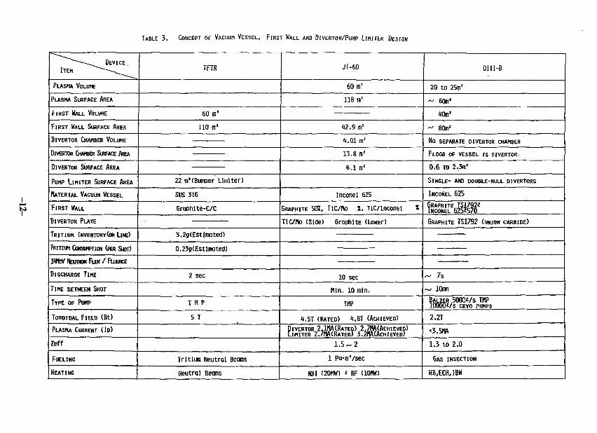
TABLE 3. CONCEPT OF VACUUM VESSEL, FIRST WALL AND DIVERTOR/PUMP LIMITER DESIGN
* " ~ - — ^ ^ ^ DEVICE .
ITEM ^ ~ ~ ' ~ \ ^ ^ ^
PLASMA VOLUME
PLASMA SURFACE AREA
FIRST HALL VOLUHE
FIRST WALL SURFACE AREA
DIVERTOR CHAMBER VOLUME
DIVERTOR CHAMBER SURFACE AREA
DIVERTOR SURFACE AREA
PUMP LIMITER SURFACE AREA
MATERIAL VACUUM VESSEL
FIRST HALL
DIVERTOR PLATE
T R I T I U M INVENTORY(ON Lite)
TRITIUM CONSUMPTION (PER SHOT)
1<KV feunuN FLUX / FLUSNCE
DISCHARGE TIME
TIME BETWEEN SHOT
TYPE OF PUMP
TOROIDAL FIELD (Bt)
PLASMA CURRENT ( I P )
Zeff
FUELING
HEATING
TFTR
60 m1
110 m1
22 m2(Bumger Limiter)
SUS 316
Graphite-C/C
3.2g(Estimated)
0.23g(Estlmated)
2 sec
T 11 P
5 T
Tritium Neutral Beams
neutral Beams
JT-60
60 m'
118 m2
12.9 m2
1.01 m1
13.8 m2
6.1 m2
Inconel 625
GRAPHITE 50Z, TIC/fto X, TiC/lnconel *
Tlc/Mo (Side) Graphite (Lower)
10 sec
Min. 10 mln.
THP
t .5T (RATED) 1.8T (ACHIEVED)
DIVERTOR 241MA(RATED) 2.7MA(ACHIEVED)L IH ITER Z.7HA(RATED) 3.JHA(ACHIEVED)
1.5-2
1 Pa-m'/sec
NBI (20HH) t RF (10HW)
DIII-D
20 to 25m'
~ 60m2
10mJ
^ 80m2
NO SEPARATE DIVERTOR CHAMBER
FLOOR OF VESSEL IS DIVERTOR-
0,6 to 2.3m2
SINGLE- AND DOUBLE-NULL DIVERTORS
INCONEL 625
GRAPHITE IS1792*INCONEL 625*570
GRAPHITE TS1792 (UNION CARBIDE)
- 7s
— lOmn
BAUER ,5000t/s TMPl O O O W S CRYO i>UMPS
2.2T
*3.5MA
1.3 to 2.0
GAS INSECTION
HB,EOUBW
Appendix I
U.S./Japan Workshop on Vacuum Technologies for Fusion Devices
List of Participants
U.S.:H.P.DyllaJ. K. JonesJ. R. HainesR. Gallix
Japan:Y. MurakamiT.AbeM. ShimizuT. AraiK. NakamuraS. HirataT. KonishiY. FujiiG. HorikoshiH. IshimaruY.TuziT. OkanoK. TeradaM. YamawakiT. BannoK. KanekoK. WatanabeS. GotoM. KondoT. UchikawaY. MikasaA. MiyaharaT. KawamuraN. NodaK. AkaishiY. SakumaA. SagaraT. KomotoY.Oka
PPPLORNLORNLGA Technologies
JAERIJAERIJAERIJAERIJAERIJAERIJAERITokyo Institute of TechnologyNational Laboratory for High Energy Physics (KEK)National Laboratory for High Energy Physics (KEK)University of TokyoUniversity of TokyoUniversity of TokyoUniversity of TokyoUniversity of TokyoUniversity of TokyoToyama UniversityHitachi Ltd.Toshiba CorporationMitsubishi Heavy Industries, Ltd.Mitsubishi Al.IPP Nagoya UniversityIPP Nagoya UniversityIPP Nagoya UniversityEPP Nagoya UniversityBPP Nagoya UniversityIPP Nagoya UniversityIPP Nagoya UniversityIPP Nagoya University
- 1 3 -
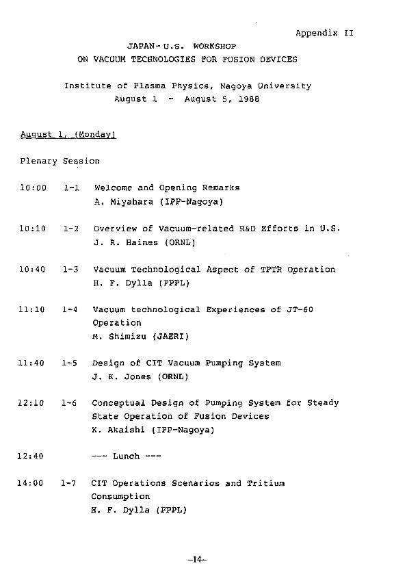
Appendix II
JAPAN -U.S. WORKSHOP
ON VACUUM TECHNOLOGIES FOR FUSION DEVICES
Institute of Plasma Physics, Nagoya University
P.ugust 1 - August 5, 1988
August 1, (Monday)
Plenary Session
10:00 1-1 Welcome and Opening Remarks
A. Miyahara (IPP-Nagoya)
10:10 1-2 Overview of Vacuum-related R&D Efforts in U.S.
J. R. Haines (ORNL)
10:40 1-3 Vacuum Technological Aspect of TFTR Operation
H. F. Dylla (PPPL)
11:10 1-4 Vacuum technological Experiences of JT-60
Operation
M. Shimizu (JAERI)
11:40 1-5 Design of CIT Vacuum Pumping System
J. K. Jones (ORNL)
12:10 1-6 Conceptual Design of Pumping System for Steady
State Operation of Fusion Devices
K. Akaishi (IPP-Nagoya)
12:40 Lunch
14:00 1-7 CIT Operations Scenarios and Tritium
Consumption
H. F. Dylla (PPPL)
-14-
14:30 1-8 Operational Experiences with Integrated Fuel
Processing at the Tritium Systems Test Assembly
(Including Operation of Compound Cryopumps with
Tritium)
S. Hirata (LANL/JAERI)
15:00 Coffee Break
15:15 1-9 Outline of the Tritium Processing Laboratory
at JAERI
T. Konishi (JAERI)
15:45 1-10 Several Experiences of Tritium-including Vacuum
Systems for Fusion Research
K. Watanabe (Toyama University)
16:15 1-11 Outgassing Mechanism from Surface and Bulk
G. Horikoshi (KEK)
16:45 1-12 ITER Vacuum Pumping System
J. R. Haines (ORNL)
17:15 1-13 Outgassing of Hydrogen from Metal Wall
M. Yamawaki (Tokyo University)
17:30 Reception
August 2, (Tuesday)
Topics Oriented Session
Pumping
9:00 2-1 Ceramic Turbomolecular Pumping System
Y. Murakami (JAERZ)
-15-
9:20 2-2 Performance Test of Ceramic Rotor
Turbomolecular Pumps
T. Abe (JAERI)
9:40 2-3 Industrial Experience with Magnetic-bearing
Turbomolecular Vacuum Pumps
J. K. Jones (ORNL)
Gauging
10:00 2-4 New Helium Detection System 'A-U Gauge'
K. Akaishi(IPP-Nagoya)
10:20 2-5 Use of Spinning Rotor Gauge for Tritium System
K. Watanabe (Toyama University)
10:40 Coffee Break
Remote Maintenance
11:00 2-6 TFTR In-vessel Remote Maintenance Manipulator
H. F. Dylla (PPPL)
11:20 2-7 CIT In-vacuum Remote Maintenance Manipulator
R. Gallix (GA)
11:40 2-8 Experience with In-vacuum Remote Manipulators
for Fusion Research
y. Murakami (JAERI)
11:55 2-9 Design and Testing of a Manipulator Arm Used in
High Vacuum
M. Kondo (Toshiba)
12:10 Lunch
First Wall, Pump Limiter, Divertor
13:30 2-10 Vacuum Scientific Interpretation of Pump
Limiters and Divertors
T. Kawamura (IPP-Nagoya)
-16-
14:00 2-11 Calculation of Pipe Conductance for Energetic
Gases by Monte Carlo Method
K. Nakamura (JAERI)
14:20 2-12 CIT Vacuum Vessel, First Wall, and Divertor
Conceptual Design
R. Gallix (GA)
14:50 2-13 ITER First Wall, Divertor, and Vacuum Vessel
J. R. Haines (ORNL)
15:20 2-14 Low Activation Al-alloy Vacuum Vessel with
Honeycomb Structure
H. Ishimaru (KEK), H. Takeraura (Mitsubishi
Al. ), A. Miyahara (IPP-Nagoya)
15:50 Coffee Break
Other Topics
16:00 2-15 Particle Balance of Thermal Neutrals in an
Ultrahigh Vacuum System Measured by the
Conductance Modulation Method
K. Terada, T. Okano and Y. Tuzi {University of
Tokyo)
16:30 2-16 Design and Operation of Pellet Injector for
JT-60
T. Uchikawa (MHI)
17:00 2-17 Plasma Driven Permeation of Hydrogen Isotopes
Y. Fujii and M. Okamoto (RLNR Tokyo Institute
of Technology)
19:00 Dinner
-17-
August 3, (Wednesday)
One Day Trip to Hiroshima
August 4, (Thursday)
Summary Session
9:30 (1) Discussion on Conceptual Design and Hardware
Requirement for the Next Step Machines,
Necessity of Background Vacuum Physics
(2) Nomination (Designation)of Collaboration Items
for the Next Workshop in U.S.
August 5, (Friday)
Visit JABRI
-18-

PLENARY SESSION
OVERVIEW
OF
VACUUM-RELATED R&D EFFORTS IN U.S.
BY
J.R.HAINES
(ORNL)
-21-
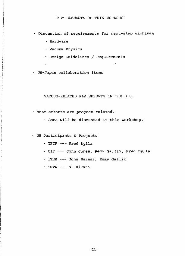
I KEY ELEMENTS OF THIS WORKSHOP
| • Discussion of requirements for next-step machines
• HardwareI! • Vacuum Physics
• Design Guidelines / Requirements
• US-Japan collaboration items
VACUUM-RELATED R&D EFFORTS IN THE U.S.
Most efforts are project related.
• Some will be discussed at this workshop.
US Participants & Projects
. TFTR Fred Dylla
• CIT —'-- John Jones, Remy Gallix, Fred Dylla
• ITER John Haines, Remy Gallix
• TSTA S. Hirata
-22-
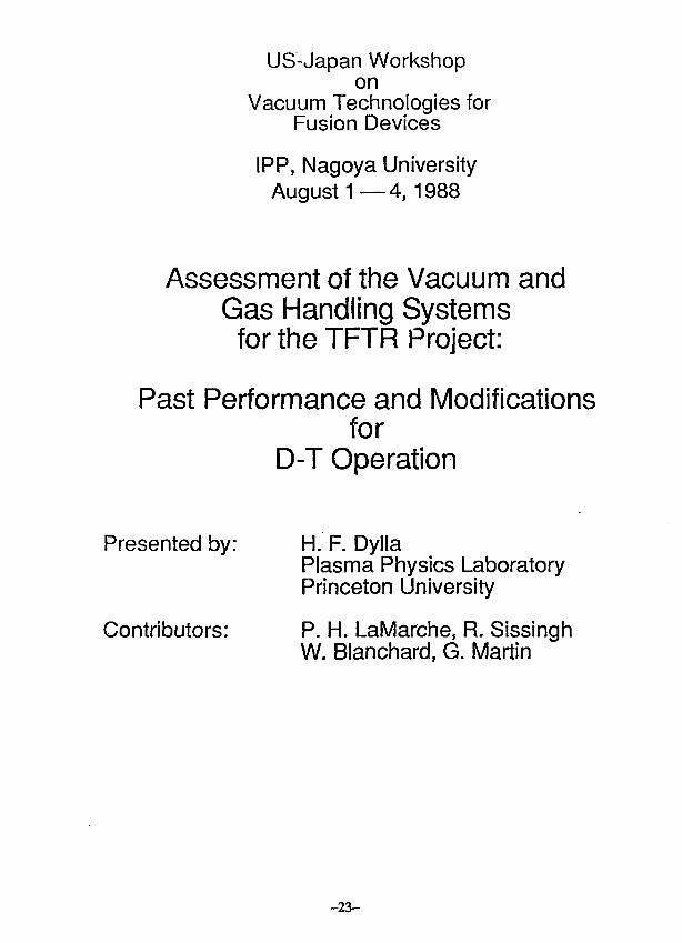
US-Japan Workshopon
Vacuum Technologies forFusion Devices
IPP, Nagoya UniversityAugust 1 — 4 , 1988
Assessment of the Vacuum andGas Handling Systemsfor the TFTR Project:
Past Performance and Modificationsfor
D-T Operation
Presented by:
Contributors:
H. F. DyllaPlasma Physics LaboratoryPrinceton University
P. H. LaMarehe, R. SissinghW. Blanchard, G. Martin
-23 -
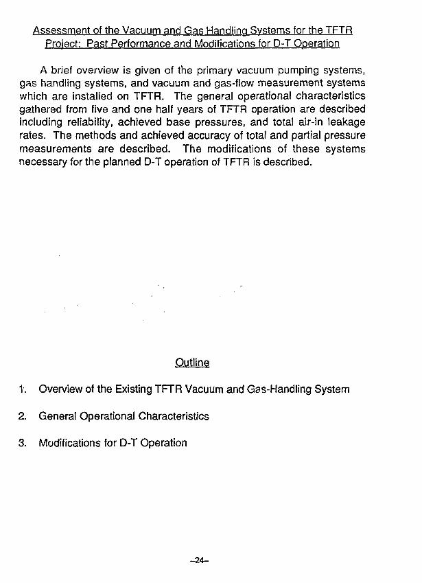
Assessment of the Vacuum and Gas Handling Systems for the TFTRProject: Past Performance and Modifications for D-T Operation
A brief overview is given of the primary vacuum pumping systems,gas handling systems, and vacuum and gas-flow measurement systemswhich are installed on TFTR. The general operational characteristicsgathered from five and one half years of TFTR operation are describedincluding reliability, achieved base pressures, and total air-in leakagerates. The methods and achieved accuracy of total and partial pressuremeasurements are described. The modifications of these systemsnecessary for the planned D-T operation of TFTR is described.
Outline
1. Overview of the Existing TFTR Vacuum and Gas-Handling System
2. General Operational Characteristics
3. Modifications for D-T Operation
- 24 -
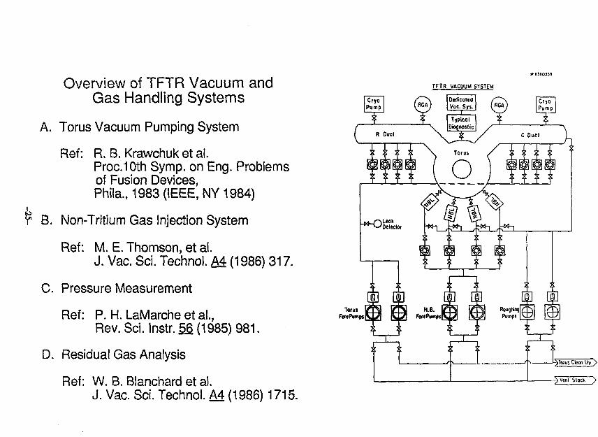
Overview of TFTR Vacuum andGas Handling Systems
A. Torus Vacuum Pumping System
Ref: R. B. Krawchuk et al.Prod Oth Symp. on Eng. Problemsof Fusion Devices,Phila., 1983 (IEEE, NY 1984)
B. Non-Tritium Gas Injection System
Ref: M. E. Thomson, et al.
J. Vac. Sci. Techno!. M (1986) 317.
C. Pressure Measurement
Ref: P. H. LaMarche et al.,
Rev. Sci. Instr. f>§ (1985) 981.
D. Residual Gas Analysis
Ref: W. B. Blanchard et al.J. Vac. Sci. Technol. A4 (1986) 1715.
TFTR VACUUM SYSTEM
TorusFwePumpj
TFTR Vacuum Svstems: Performance
TVPS28amu
5,000 l/s
2amu
Pumping Speeds 9,000 l/s
Pumping Time Constant 9.5 s 17.2 s
Torus
Leak Rate (air equivalent)
Specification 1 x 10⁻⁷ Torr - l/s
Achieved Range 4x10⁻⁶-4x10⁻⁵ Torr - l/s
Desired Range 5 5x10⁻⁶ Torr - l/s
Base Pressures
Total 1 -3x10⁻⁹ Torr
Impurities (Z > 2) < 10-9 Torrs
~ omi
•. S00 31
8
3 :09
m -J w
"1
Discussion Topic:
What parameters are relevant for sizing thevacuum pumping requirements for the nextgeneration of tokamaks?
1. Net hydrogenic pumping speed (amu)— pumping time constant (V /SH)
2. Net impurity pumping speedsjb (16,18,28,44 amu)f1 — pumping time constant (V/S{)
3. Maximum acceptable hydrogenic basepressures
4. Maximum acceptable impurity basepressures
Contention: Requirement four sizes:— vacuum pumping system— maximum leak rate— maximum outgassing rates
#84X1106
SELECTEDvGAS } ORUS
PPL
TFTR GAS INJECTOR
- 2 & -
o
175
150
125
100
75
50
25
0
1 < 1
Volve Volts
1 5 0 A^-""""
" ^ ^ ^ 120
B J2~~^~°'"
' ^ (0) -
-
-
- Q
1 1
1000 I ZOO 1400 1600 1800 2000
FILL PRESSURE (TORRl
0.025
8
Plasma
Im
#84X1275
TF Coil
AMU"
£,.
Vacuum Metrology on TFTR
Primary vacuum standard is a spinning rotor gaugelocated on an off-site calibration system
Secondary standards (capacitance manometers)are checked against the S.R.G.
Torus ionization gauges are calibrated prior toinstallation:
— after installation, calibration is checked 1-2per year against torus capacitancemanometer and more frequently as part ofgas injection valve calibration.
RGA is calibrated in-situ during every maintenanceperiod (monthly)
Estimated accuracy of absolute pressurecalibrations
typical ± 10%best ± 5%
RGa-i
TFTR Torus Vacuum
Pumping Ouct
TMPI
j. /^l Gas HandlingW \ ] """ System
Quadrupole MassSpeclromeler
TMP2
Oiflereniial Pumping
TFTR RESIDUAL GAS ANALYZER IRGA)
Dynamic ton Gauge Calibration (He)
600
600-
20 40 60 80 100
Ion Gauge F low (N2 eqlv.)
- 3 1 -
TORR RCA • « IAV)
UNPROCESSED TEST SCAN
FIRST MASSSCAN UIOTHRESOLUTIONSEM UOLTAGESCAM flS/ATIUClIRR RANGRnM FACTORFILTER MSEC
a.OS44.eeS3.tW1698.ie«.
-5.ee1.00
te.eaCALIBRATION FACS
USER SUPPLIED
« U TORR/WIPi.eee+9i.eoeta.««£•«.ee£+8.eeE+e
11*3ee
to.-7
eeEe.oee+o.eee+e.eee+eeee«
o .eee+eSCAN SEARCH BEGAN
ON 0/ 00 01 0
t«
10
1-8-
ION
GAS TCWAflPHVDROCEN 2 . 8 S E * *HE1IUN 1.44E+1rCTHANE 3.S7E*«OH 4.01E+4UATER 4.«lE+«CON .89E41NITROGENmoonSet 1.2«H-5 TORR
10ATU
SCAN ERROR! NONE
-37r-
Modification for D-T Operation
A. Vacuum Pumping Systems
• Tie in of all vacuum systems (TVPS, NBVS,Diagnostics) exhausts to Tritium RecoverySystems
— Plasma Exhaust Tankor
— Gas Holding Tank
• Removal of one pumping duct (Bay R) andreplacement by maintenance manipulator
• Removal of two TMP's from Bay C pumpingduct and replace with two 20°K cryopumpsfor impurity pumping during dischargecleaning.
— Gas conservative discharge cleaningmodes have been proposed for D-Toperation
• All high power plasma pumping will beprovided by four Neutral Beams (140 kl/s netfor 2 amu)
B. Gas Injection Systems
• Three new Gas Injection Assemblies will beadded for tritium gas injection (one requiredfor 150 tl/s input and two for backup).
• Tritium gas injectors being installed on fourneutral beam lines (only six sources will betritium fueled at maximum)
C. Pressure Measurement
• RGA being re-installed outside iglooshielding
• Differential pumping used on RGA (standardGDC mode) to minimize tritium exposure toelectron multiplier.
TRITIUM GAS HANDLING DURING VESSEL CONDITIONING
Conditioning Modes Pressure(Torr)
GDC-Standard 5 x 1 0 ' 3
GDC-Low-Throughput1 >2 5 x 10"3
TDC-Standard 1 x 10"4
TDC-Low-Throughpuf .2 1 x 10"4
PDC-Standard 1 x 1(rs
PDC-Low-Throughput1'2 1x10" 5
He-Ohmic Discharge3 3 x 10 - s
Pumping Speed Gas(liters/sec)
5 x 1 0 3
see note 2
1 x10*
see note 2
1 x i O 4
see note 2
1 x 1 0 4
HydrogenicThroughput(Torr liters/hr)
H,D,T
H,D,T
H.D.T
H.O.T
H,D,T
H.D.T
1 x 10⁵
4 x 1 0 2
4 x 1 0 3
1 x10
4 x 1 0 2
1
He,(H,D,T) 24minority
Time
1 day
1 day
2 days
2 days
2 days
2 days
2hrs
Quantity(torr liters)
- 2 x 1 0 6
-1 x10 4
- 2 x 1 0 5
- 5 x 1 0 2
- 2 x t O 4
50
48
1. Assumes operation only with proposed torus ciyopumps with an elfective impurity speed ol 5,000 liters/s.2. Assumes one exchange ol hydrogenic gas level per hour through TVPS.3. Assume 24 pjlse/hr.
GDC: Glow Discharge CleaningPDC: Pulse Discharge CleaningTDC: Taylor-type Pulse Discharge Cleaning
TRITIUM FLOW THROUGH TFTR
_J
-34 -
rtJLTiPLIEK WMHWeS
CUUATK T2 KOSUt TDRR-S
MJLTIPLIER CUIPUIS DURING DPOSURES
nr° 10" 7 10" 6 W5
T 2 EXPOSURE WESSURE, TORR
-35 -
VACUUM TECHNOLOGICAL EXPERIENCES OF JT-60 OPERATION
M. SHIMIZU AND T. ARAI PRESENTED BY SHIMIZU
JAPAN ATOMIC ENERGY RESEARCH INSTITUTE
NAKA FUSION RESEARCH ESTABLISHMENT
MUKOYAMA, NAKA-MACHI, IBARAKI-KEN, 311-01 JAPAN
- VACUUM PROPERTY
- CONDITIONING
- VACUUM LEAK
- VACUUM CONTROL CRITERIA
-36-
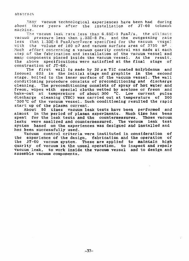
abstract
Many vacuum technological experiences have been had duringabout three years after the installation of JT-60 tokamakmachine.
The vacuum leak rate less than 6.65E-S Pam3/s. the u J'l fniai-:-vacuuc pressure less than 1.33E-6 Pa, and the outg-assing- rateless than 1.33E-S Pau!3/scn-2-,vere specified for the vacuum vesselwith the volume of 160 s>3 and vacuum surface area of 2750 m2 .Much effort concerning a vacuum quarity control was made at eachstep of the fabrication and installation of the vacuum vessel andmany conponents placed inside the vacuum vessel. As the result,the above specifications were satisfied at the final stage ofconstraction of JT-60.
The first wall is made by 20 vm TiC coated molybdenum andInconel 625 in the initial stage and graphite in the secondstage, bolted to the inner surface of the vacuum vessel. The wallconditioning procedure consists of preconditioning and dischargecleaning. The preconditioning consists of spray of hot water andfreon, wipes with special cloths wetted by acetone or freon andbake-out at temperature of about 300 CC. Low current pulsedischarge cleaning (TDC) was carried out at temperature of 200"300°C of the vacuum vessel. Such conditioning resulted the rapidstart up of the plasma current.
About 50 times vacuum leak tests have been performed andalmost in the period of plasma experiments. Much time has beenspent for the leak tests and the countermeasures. Those vacuumleaks were analized and countermeasured. The vacuum leak testsystem based on the experiences was designed and installed andhas been successfully used.
Vacuum control criteria were instituted in consideration ofthe experience of the design, fabrication and the operation ofthe JT-60 vacuum system. These are applied to maintain highquarity of vacuum in the usual operation, to Inspect and repairvacuum leak, to work inside the vacuum vessel and to design andassemble vacuum components.
-37-
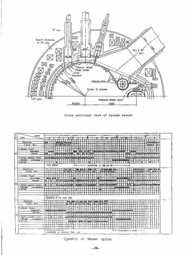
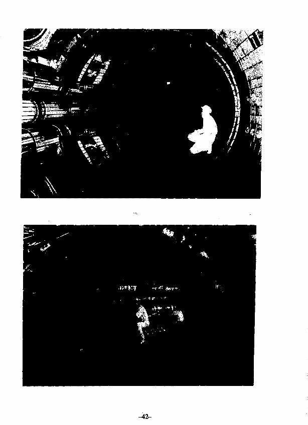
Cross sectional view of vacuum vessel
M i l l ' n n T P i T m i i i i n r r i T T n
Operoiion of Vacuum system
- 3 8 -
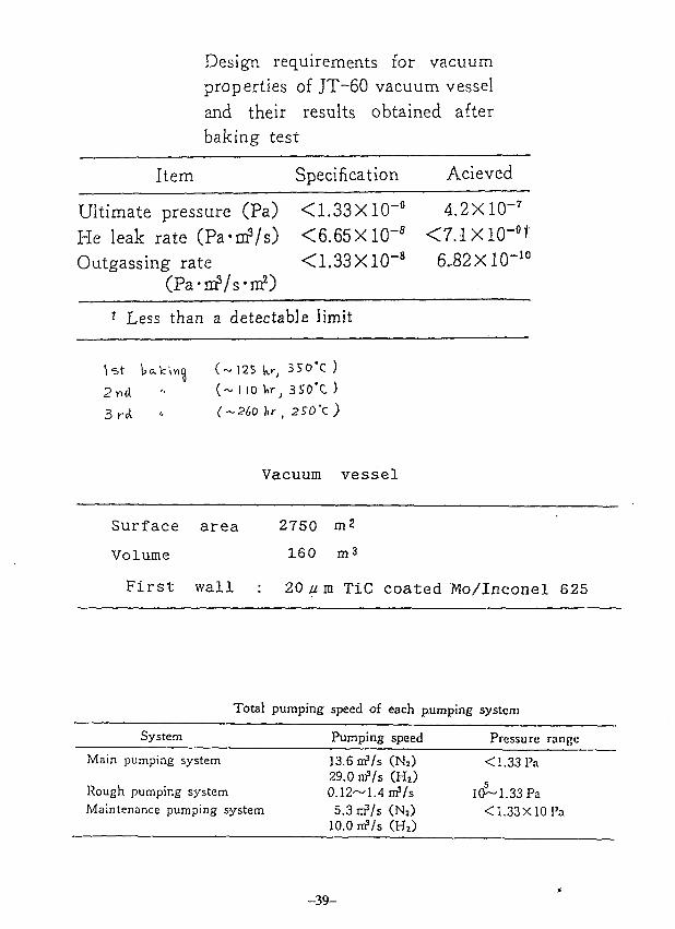
Item
Design requirements for vacuumproperties of JT-60 vacuum vesseland their results obtained afterbaking test
Specification Acieved
Ultimate pressure (Pa) <1.33Xl(r6 4.2X10⁻⁷
He leak rate (Pa-cop/s) <6.65Xl(r8 <7.1X10"BtOutgassmg rate <1.33X10⁻⁸ 6..82XKT10
(Pa-DD?/s'irf)r Less than a detectable limit
2 n d
(~ 125 k<-, 3SO'C )
(~ I 10 Vr, 3S0*C )
(~2bO hr , )
Vacuum vessel
Surface area
Volume
First wall
2750 m2
160 m3
20/im TiC coated Mo/Inconel 625
Total pumping speed of each pumping system
System Pumping speed Pressure; range
Main pumping system
Rough pumping systemMaintenance pumping system
13.6 nrVs (Ns)29.0 niVs CH2)0.12~1.4irf/s5.3 nf/s (Ns)
10.0 nfVs (H2)
< 1.33 Pa
10~1.33 Pa< 1.33X10 Pa
-39-
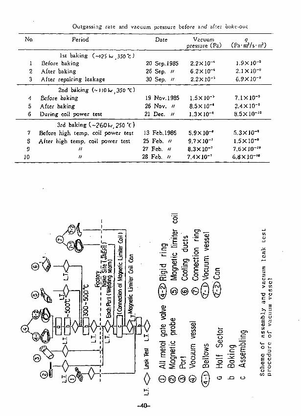
No.
Outgassing rate and vacuum pressure before and after balcc-out
Period Date Vacuumpressure (Pa) (Pa-rrrVs-ni2)
123
/(
56
7
S9
10
1st baking (~I2S hr _330"c )Before bakingAfter bakingAfter repairing leakage
2nd baking (-)l0Kr,350 X)Before bakingAfter bakingDuring coil power test
3rd baking (~26(Hr,250 *c)Before high temp, coil power testAfter high temp, coil power test
//
20 Sep.198526 Sep. //30 Sep. //
19 Nov. 198526 Nov. //21 Dec. //
13 Feb. 198625 Feb. //27 Feb. "28 Fab. "
2.2 X10⁻¹
6.2X10'°2.2X10⁻¹
1.5X10⁻¹
8.5X10-°1.3X10-"
5.9 X10-'9.7X10"'8.3X10"'7.4 X10"'
1.9X10-°2. IX 10"'
.G.9X10-"
7.1X10"°2.4X10-"{J.5X10-10
5.3X10"'1.5X10"'7.GX10"'0
6.8 X10⁻¹⁰
JQ O
5 >xr.
O •-
a ~
J= Oo i.
GO 2.
-40-
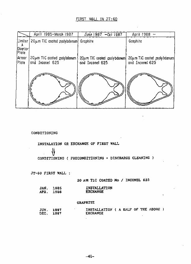
FIRST WALL IN J T - 6 0
April 1985-March 1987 June 1987 -0cfl987 April 1988 -
Limiter4
Diver forPlateArmorPlate
20/xm TiC coated molybdenum
20/im TiC coated molybdenumand Inconel 625
Graphite
20/xm TiC coated molybdenumGnd Inconel 625
Graphite
20,umTiC coated jn.olybdenumand Inconel 625
CONDITIONING
INSTALATION OR EXCHANGE OF FIRST WALL
CONDITIONING ( PRECONDITIONING + DISCHARGE CLEANING )
JT-60 FIRST WALL
JAN. 1985APR. 1986
20 UK TiC COATED Mo / INCONEL 625
INSTALLATIONEXCHANGE
JUN. 1987DEC. 1987
GRAPHITE
INSTALLATION { A HALF OF THE ABOBE )EXCHANGE
-41-
-42-
PRECONDITIONING OF VACUUM VESSEL
(1) REMOVAL OF DUST IN AIR BY USING A MICRON FILTER CLEANER
(2) SPRAY OF HOT WATER BY JET SPRAY GUN
(3) SPRAY OF FREON BY JET SPRAY GUN
(4) WIPING OF INNER SURFACES BY SPECIAL CLOTHS WETTED
WITH ACETONE OR FREON
(5) BAKE OUT OF VACUUM VESSEL
-43-
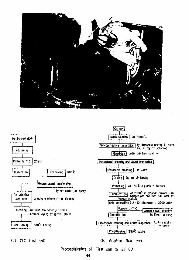
Mo.inconel 625
±Machining
Coated by TiC 20 pm
Inspection Prebaking 500°C
Vacuum vessel precltaning
InstallationOust free
by hot water jet sproy
by using o micron filter deoner
Cleaning by freon and water jet sproyAcetone wiping by special cloths
Conditioning 35C*C baking
U ) T i C firs? wol!
| Grophilizolion [ ot 3000°C
II Non-destructive inspection I by ultrasonic testing in water
1 ' and K-ray CT scorming
| Machining | under oil- free condition
I ,[Dimensional checking and visuol inspcciion |
| Ultrasonic cleaning | in water
| Prying | by hot air blowing
| PreboKing | ot l 5 0 t in graphite furnocc
I Purif irntionl n ' 2000*C in graphite furnace wiih| purification [ ^ ^ 0 * j wjUi jncr( ^IVacuum pocking
| Unit assembling | 2 - 1 0 tilcs/unil x ZGOO units
\ftcuum pocking
| Instollotion |j Vbojjm vessel clcaniivi j
by Frcon jet sproy
I Dimenskmol checking and visual inspection I Awtonu wipiny1 1—*— ' i! nci:cssary
[ Conditioning 1 350*C coking
(b) Graphite first wall
Preconditioning of First wall in JT -60
o—— o 10101 f»C• • M/e 2
M/e 14M/e 16M/e 18
*• * M/e 28x x M/e 43x x M/e 44
M/e 57
1010' 14 18 22 2 6 10 14 18 22 2 6 10 14 18 22 2 6 10 14 16 22 2 6 10
Ain/13 II 15 16 17
Pressure curve of typical Boking in J T - 6 0
10'
RGA(A)
I 0 7
10'
10s
0 1 2 3 4 5 6 7!„ — xl00(A)
Ip(kA)
10
RGA(A)
io6
id7
IO8
: f> :
i :: i
i
\ / i
\
i i i t
10'
P(PO)
10*
- 10J
100
sotIp
(kA)
0 0.4 0.8 1.2 1.6Q(Po-mVs)-*
I6
Studies of TDC optimized condition by vertical field currcnt(J.v) ,gas feed rate(Q) and toroidal field(Bt)
o
S
Final vacuum pressure in TiC wall and Graphite wall
Patial pressure
Total Pressure
M/e=2(H2)
M/e = 12 (C)
M/e = l6 (C 2 H 4 )
M/e = I 8 ( H 2 0 )
M/e=28(C0,C2H4)
M/e=44 (C02>
TiC Wall fAip/7/1985)(Pa)
4.05 x IO"T
3.32 x IO"7 (82%)
6.3 x i 6 "
4.4 x | J 9
4.49 x 10'9
1.22 x I0 8
4.88 x 10⁹
Graphite Wall (Aug./I4/I987)(Pa)
1 "3.99
8.2
1.96
8.7
6.8
8.2
X
X
X
X
X
X
X
I 0 7
10'7 (62% 1
16"
to8
,68
Id8
.69
CDcc
od
U J
iRA
PH
I"
1
S6
2.6
c
C3ooo
1111
CO
M/e
= 1
X
CO
M/e
=
1
o •
Ay/
1
CO
M/e
=5
< •<
x 4
X
//
A
/X
/
x'X
1
-
•
o
O 00— O!
HS I
- oI— -3
CJ
5to0!G
(V)
-47-
kf
Time (sec)
Irm
SF ?
S 9.
5 8" 'i
Tl»c history or naln plasma discharges Just a f t t r conditioning.Hunbcr M?3S corre.iponds Lo the f i rs t t r i a l .
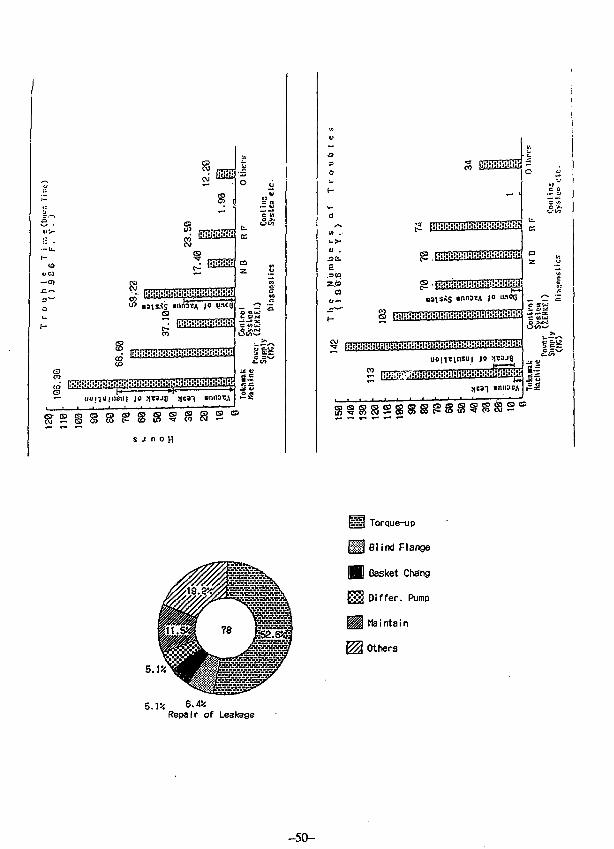
Cause of Uacuum Leakage
3.8%5.1*
2.
| Elect.mag. F
| Torque-down
| Misassembl.
I Thermal Strn
| Bad danufac.
t Others
] Metal 0 r i ng
] Copper Gaskt
| Bonnet of GU
j Disk Seal GU
| Others
I Not clear
Place of Uacuum Leakage
-49-
41 CO
— o
- - j
Jo -1
until
.3(0
z.c>
fc.c
az
C C— O
C SUJ
•ss
3 Torque-up
I Blind Flange
I Gasket Chang
I Differ. Pump
I Maintain
Others
Repair of Leakage
-50-
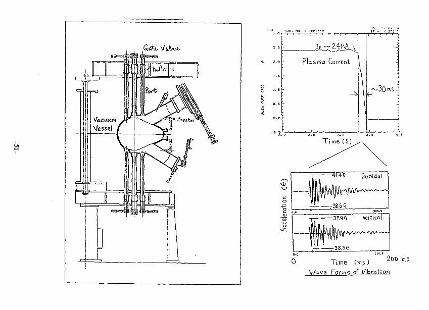
2-.sE-
.= 2.eh
4 * * • " I
Plasma Current
3 .0 3.S
T i m e ( S '
oo
0-0
0
•1.4 fr Toroidal
38.5 5
Vertical
38.55.
Time (ms)
Wave Forms of Vibration
2oo vn 5
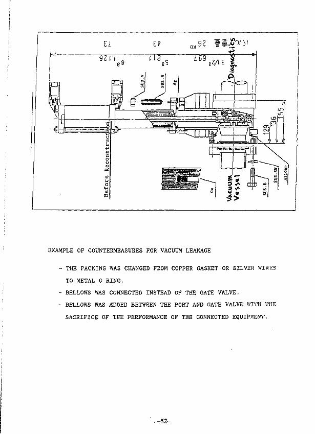
EXAMPLE OF COUNTERMEASURES FOR VACUUM LEAKAGE
- THE PACKING WAS CHANGED FROM COPPER GASKET OR SILVER VVIIUCS
TO METAL 0 RING.
- BELLOWS WAS CONNECTED INSTEAD OF THE GATE VALVE.
- BELLOWS WAS ADDED BETWEEN THE PORT AND GATE VALVE WITH THE
SACRIFICE OF THE PERFORMANCE OF THE CONNECTED EQUIPMENT.
.-52-
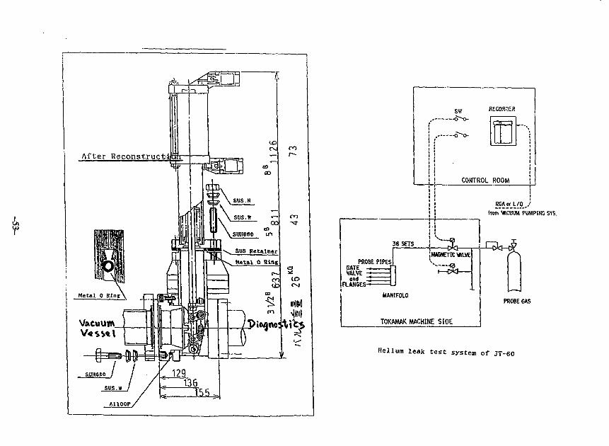
A,
After Reconstruct!
j Metal 0 Bint'
i
COCO
--tJ_5>
s w RECOSOEfi
--o-o-
36 SETS
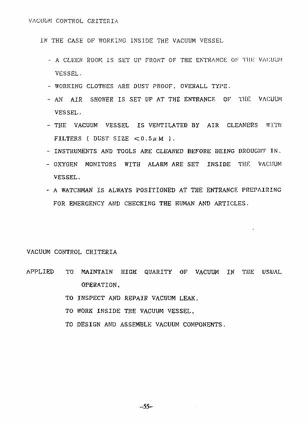
CONTROL ROOM
from VftCUUM PUMPING SYS.
MAGNETIC VALVEPROBE PIPES!
GATEVALVE
ond _FLANGES-
'.
MANIFOLD
TOKAMAK MACHINE SIDE
PROBE GAS
Helium leak t e s t system of JT-60
10
I—' I I . ' I l l l l T i i i i mi|—i i i MI»|—i i > IIIII|—i i i inn)—i—m
level I : watching under theplasma operation
level u : imposible plasma operation
evaluation on H.L.Oevoluotion on vacuumpressure gage
' 1 ' I l l l l l 1—I I I l l l l l i i ' m i l l I i I m i l l ' i i l l i l i i l i i i I I I I I I i i i i i l i i l I I I i u l i
10"8 \67 I0'6 I0"5 I 0 4 I0"3 10'2
leak rate (Pa m3/s)
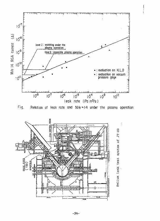
Fig. Relation of leak rate and M/e = l4 under the plasma operation
•<mr
o
E0)
•p
E
- 5 4 -
VACUUM CONTROL CRITERIA
IN THE CASE OF WORKING INSIDE THE VACUUM VESSEL
- A CLEEN ROOM IS SET UP FRONT OF THE ENTRANCE OK Till.-: VACUUM
VESSEL.
- WORKING CLOTHES ARE DUST PROOF. OVERALL TYPE.
- AN AIR SHOWER IS SET UP AT THE ENTRANCE OF THE VACUUM
VESSEL.
- THE VACUUM VESSEL IS VENTILATED BY AIR CLEANERS WITH
FILTERS ( DUST SIZE <0.5^M ).
- INSTRUMENTS AND TOOLS ARE CLEANED BEFORE BEING BROUGHT IN.
- OXYGEN MONITORS WITH ALARM ARE SET INSIDE THE VACUUM
VESSEL.
- A WATCHMAN IS ALWAYS POSITIONED AT THE ENTRANCE PREPAIRING
FOR EMERGENCY AND CHECKING THE HUMAN AND ARTICLES.
VACUUM CONTROL CRITERIA
APPLIED TO MAINTAIN HIGH QUARITY OF VACUUM IN THE USUAL
OPERATION,
TO INSPECT AND REPAIR VACUUM LEAK,
TO WORK INSIDE THE VACUUM VESSEL,
TO DESIGN AND ASSEMBLE VACUUM COMPONENTS.
-55-
- WE HAVE HAD MANY VACUUM TECHNOLOGICAL EXPERIENCES.
- VACUUM PROPERTY
- CONDITIONING
- VACUUM LEAK
- VACUUM CONTROL CRITERIA
- OUR VACUUM TECHNIQUES FRUITFULLY CONTRIBUTED TO PLASMA
EXPERIMENT.
- WE WILL PREPAIR TO INPROVE OUR VACUUM TECHNIQUES IN
CONSIDERING OF OUR EXPERIENCE AND THE OTHER EXAMPLES ETC.
VACUUM CONTROL CRITERIA
MAIN DESIGN CRITERIA OF THE VACUUM COMPONENT
- A GASKET IS ICF COPPER GASKET OR METAL 0. RING.
- BAKING TEMPERATURE IS AS RULE MORE THAN 250°C.
- OUTGASSING RATE IS LESS THAN 1.3 X 10~8 Pam3/sm2.
- HELIUM LEAK RATE IS LESS THAN 1.3 x 10~10Pain3/s.
- AN EQUIPMENT CONNECTED TO THE VACUUM VESSEL HAS
AN EXCLUSIVE PUMPING SYSTEM.
-56-
DESIGN OF CIT VACUUM PUMPING SYSTEM
JOHN K. JONESOAK RIDGE NATIONAL LABORATORY
PRESENTED ON AUGUST I, 198«AT THE INSTITUTE OF PLASMA PHYSICS
NAGOYA UNIVERSITY
-57-
Abstract
The design of the CIT vacuum system is discussed.
A conceptual design of the vacuum system has been completed
to accommodate the vacuum pumping requirements of the CIT
with a torus major radius increased to 2.1m. A description
of the current CIT facility configuration is given, along
with the location of the vacuum pumping equipment to permit
hands-on maintenance of the vacuum equipment. The design of
the vacuum system design is described and utilizes equipment
capable of handling tritium. Proposed vacuum equipment
design utilizes turbomolecular, scoll and diaphragm pumps,
and other components. Information on the operational
experience with any of these proposed components as a system
by other delegates is requested.
-58-
CIT OVERVIEW
• LOCATED AT PPPL ADJACENT TO TFTR
• UTILIZES TFTR SYSTEMS TO MINIMIZE COST
• TEST CELL IS RECTANGULAR IN CROSS SECTION
• REMOTE MAINTENANCE ACCESS TO CENTER CELL
• VACUUM PUMPING OF TORUS THROUGH SINGLE DUCT
• VACUUM EQUIPMENT LOCATED IN BASEMENT
PRESENTATION OUTLINE
• CIT OVERVIEW
• VACUUM SYSTEM REQUIREMENTS
• SYSTEM DESIGN
• PUMPING EQUIPMENT
• SUMMARY
-59-
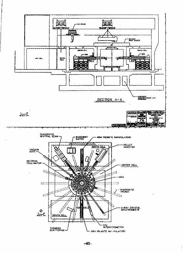
DIAGNOSTICNEUTRAL BEAM ABM [REMOTE MANIPULATOR)
-CENTER CELL
-X-RAV CRYSTALSPECTROMEETR
THOMSONSCATTERING
CO}INTERFEROMETER
ABM (REMOTE MAVPULATOR)
-40-
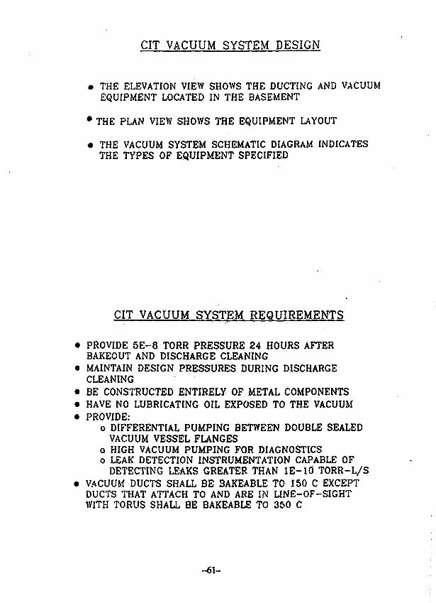
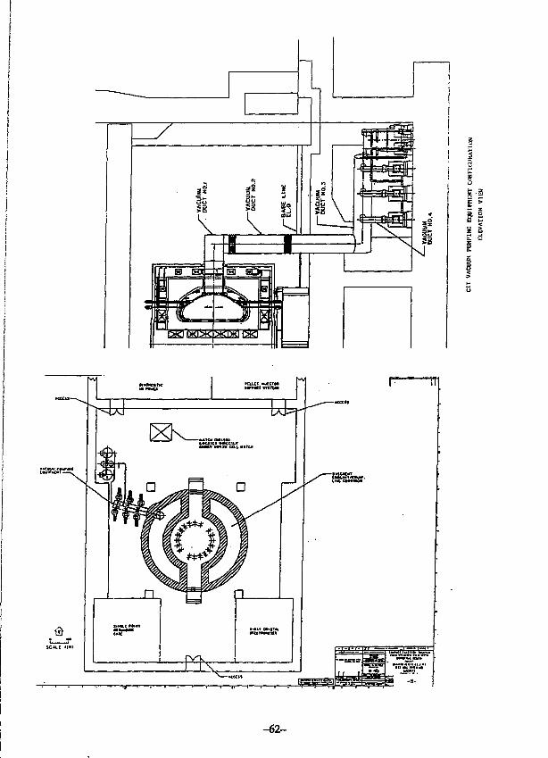
CIT VACUUM SYSTEM DESIGN
• THE ELEVATION VIEW SHOWS THE DUCTING AND VACUUMEQUIPMENT LOCATED IN THE BASEMENT
• THE PLAN VIEW SHOWS THE EQUIPMENT LAYOUT
• THE VACUUM SYSTEM SCHEMATIC DIAGRAM INDICATESTHE TYPES OF EQUIPMENT SPECIFIED
CIT VACUUM SYSTEM REQUIREMENTS
PROVIDE 5 E - 8 TORR PRESSURE 24 HOURS AFTERBAKEOUT AND DISCHARGE CLEANINGMAINTAIN DESIGN PRESSURES DURING DISCHARGECLEANINGBE CONSTRUCTED ENTIRELY OF METAL COMPONENTSHAVE NO LUBRICATING OIL EXPOSED TO THE VACUUMPROVIDE:
o DIFFERENTIAL PUMPING BETWEEN DOUBLE SEALEDVACUUM VESSEL FLANGES
o HIGH VACUUM PUMPING FOR DIAGNOSTICSo LEAK DETECTION INSTRUMENTATION CAPABLE OF
DETECTING LEAKS GREATER THAN I E - i d TORR-L/SVACUUM DUCTS SHALL BE 3AKEABLE TO 150 C EXCEPTDUCTS THAT ATTACH TO AND ARE IN LINE-OF-SIGHTWITH TORUS SHALL BE BAKEABLE TO 350 C
- 6 1 -
i i
SiS §
-62-
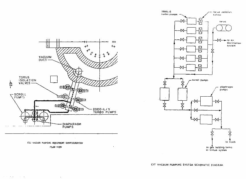
TORUSISOLATIONVALVES
2OOO-L/STURBO PUMPS
DIAPHRAGMPUMPS
CIT VACUUM PUMPING EQUIPMENT CONFIGURATION
I'LAN VIEW
2000L/Sturbo pumps —•,
/—• torus isolationVi'll VCS
—1X1-
-S[X]— +- to air
dctritioiionsystem
) /— scroll pumps
31
T T
/pumps
HXh - t > 4 -
to gis holding tanksin Iritum system
CIT VACUUM PUMPING SYSTEM SCHEMATIC DIAGRAM
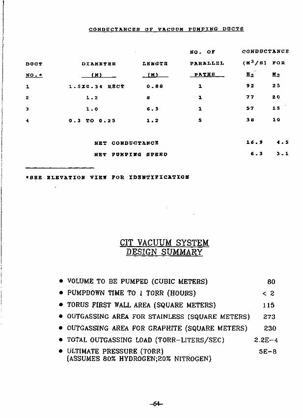
CONDPCTAMCEB OF VACPPH PPMPXNG DOCTS
DUCT
NO. *
1
2
3
4
DZAKETER
(H)
1.SZ0.34 RBCT
1. 2
1.0
0.3 TO 0.25
LENGTH
(H)
0.88
8
6.3
1.2
NET CONDDCTAHCE
NET PUHPIWG SPEED
NO. OF
PARALLEL
PATHS
1
1
1
5
CONDUCTANCE
(M3/8) FOR
H 2 5.2
92 25
77 20
57 15
38 10
16.9 4.5
6.3 3.1
•SEE ELEVATION VIEW FOR IDENTIFICATION
CIT VACUUM SYSTEMDESIGN SUMMARY
• VOLUME TO BE PUMPED (CUBIC METERS) 80
• PUMPDOWN TIME TO 1 TORR (HOURS) < 2
• TORUS FIRST WALL AREA (SQUARE METERS) 115
• OUTGASSING AREA FOR STAINLESS (SQUARE METERS) 273
• OUTGASSING AREA FOR GRAPHITE (SQUARE METERS) 230
• TOTAL OUTGASSING LOAD (TORR-LITERS/SEC) 2 . 2 E - 4
• ULTIMATE PRESSURE (TORR) 5 E - 8(ASSUMES 80% HYDR0GEN;20% NITROGEN)
- 6 4 -
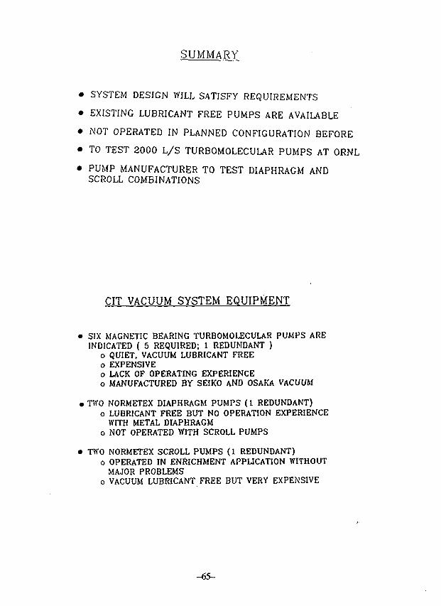
SUMMARY
• SYSTEM DESIGN WILL SATISFY REQUIREMENTS
• EXISTING LUBRICANT FREE PUMPS ARE AVAILABLE
• NOT OPERATED IN PLANNED CONFIGURATION BEFORE
• TO TEST 2000 L / S TURBOMOLECULAR PUMPS AT ORNL
• PUMP MANUFACTURER TO TEST DIAPHRAGM ANDSCROLL COMBINATIONS
CIT VACUUM SYSTEM EQUIPMENT
• SIX MAGNETIC BEARING TURBOMOLECULAR PUMPS AREINDICATED ( 5 REQUIRED: 1 REDUNDANT )
o QUIET. VACUUM LUBRICANT FREEo EXPENSIVEo LACK OF OPERATING EXPERIENCEo MANUFACTURED BY SEIKO AND OSAKA VACUUM
• TWO NORMETEX DIAPHRAGM PUMPS (1 REDUNDANT)o LUBRICANT FREE BUT NO OPERATION EXPERIENCE
WITH METAL DIAPHRAGMo NOT OPERATED WITH SCROLL PUMPS
• TWO NORMETEX SCROLL PUMPS (1 REDUNDANT)o OPERATED IN ENRICHMENT APPLICATION WITHOUT
MAJOR PROBLEMSo VACUUM LUBRICANT FREE BUT VERY EXPENSIVE
-65-
Conceptual Design of a Closed Vacuum
Pumping System Using Turbomolecular Pump for Fusion Reactor
BY
K. Akaishi
Institute of Plasma Physics
Nagoya University
Nagoya 464-01
Japan
-66-
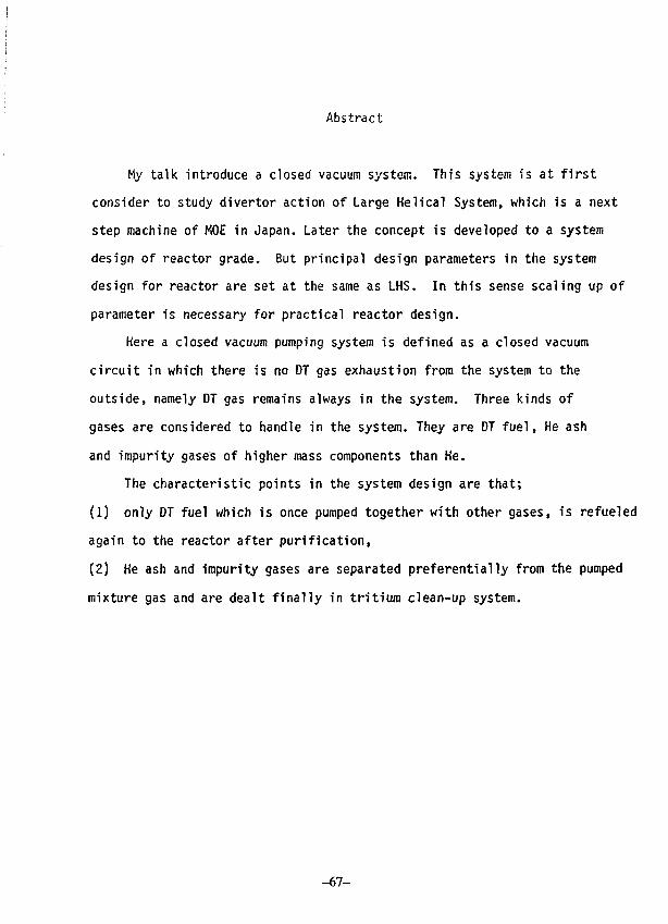
Abstract
My talk introduce a closed vacuum system. This system is at first
consider to study divertor action of Large Helical System, which is a next
step machine of MOE in Japan. Later the concept is developed to a system
design of reactor grade. But principal design parameters in the system
design for reactor are set at the same as LHS. In this sense scaling up of
parameter is necessary for practical reactor design.
Here a closed vacuum pumping system is defined as a closed vacuum
circuit in which there is no DT gas exhaustion from the system to the
outside, namely DT gas remains always in the system. Three kinds of
gases are considered to handle in the system. They are DT fuel, He ash
and impurity gases of higher mass components than He.
The characteristic points in the system design are that;
(1) only DT fuel which is once pumped together with other gases, is refueled
again to the reactor after purification,
(2) He ash and impurity gases are separated preferentially from the pumped
mixture gas and are dealt finally in tritium clean-up system.
-67-
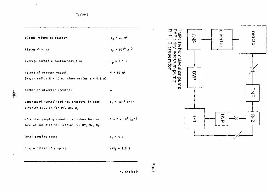
Table-1
Plasma volume 1n reactor
Plasma density
average particle confinement tine
Yp - 30 m3
ne • 1020 m'3
T p - 0.1 s
volume of reactor vessel V « 50 n^
(najor radius R • 10 m, minor radius » • 0.5 n)
number of dlvertor sections •
compressed neutralized gas pressure In each PQ • 10"^ Torr
dlvertor section for DT, He, Ng
effective pumping speed of a turboraolecular s • S > 10^ is"*
pump at one dlvertor section for OT, Ne, N2
Total pumping speed
time ocnstant of punpfng
ST - 4 S
V/ST • 2.5 S
K. Akafshf-
T«bU-:
Conventional t ip- (Ktt-nol-M. Co. "*-»»*)
tnn")
I
r.•tt/t(Torr)
-
a
•S/I
5X101
10*
sxio-"
1IS0
o.on
io-»
5X10'
IX10*"
1(50
11.033
I-IX10**
10"
„,,.-.
1150
l . 'S
IX 10"*
. . .
1 X 1 0 "
1(5.0
11. *
1.
1.
Sxio-'
10
Sxio-f
£<00
<0
•
10'
„-..
1100
I.IX10
t
1
IX 101
IX 10""
1100
-• 1.11
I IIM (Ouli • « • • . . C. TC-SSI)
r>(T«rr)
t
r.•f i / t•(t.rr)
S
•J / I .
hI I - 1 i.Sxil-
S«ll' II*
tx !«-'• |SX10"
Sll 111
l.t >
III II
ix ll-taxil-'
HI i l l
1x.ll-> J.) l.t. l.tx||-'
ii*1 I.
Ixn" 1
-x,.-.
I l l
l.lxll-I
1 .
xll-
,x, l
SSI
ixll' itxil*
IX1I-*
Sll XSSI
1 1.HXII-".1X10** - IXH-*
Ixll-
I I 1
Ixll-
SSI
S.IX
11 J
I I '
IX11"
SSI
<
IX10*
sxii-'
SSI
1
I I '
I x l l "
ssi
•-• I.IXII-*S.Sxll" I.Sxll-*
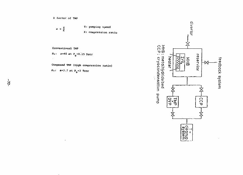
A factor of TMP
"ftS: pumping speed
K: compression ratio
Conventional TMP
I!,: a=40 at Pb-0.15 Torr
Compound TMP (High compression ratio)
tit: a=3.7 at P =3 Toxrb
<
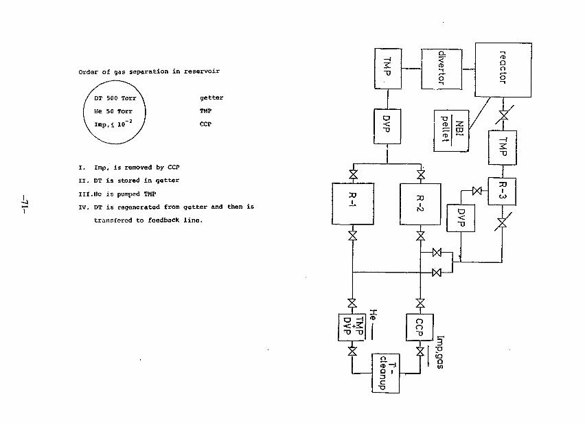
Order of gas separation in reservoir
getter
TMP
CCP
I. Imp, is removed by CCP
II. DT is stored in getter
III.He is pumped TMP
IV. DT is regenerated from getter and then is
transfcred to feedback line.
Summary
1. The closed vacuum pumping system which consists of TMP, OVP,
reservoir, gas separator, is considered.
2. The role of DVP as a compressor is important and its
reliability becomes important in future.
3. To use two kinds of TMPs which have different values of a
factor is required for circulation and feedback of OT fuel.
4. The important role of reservoir is to perform the function of
gas separation and the R&D is needed for the best design.
-72-
US-Japan Workshopon
Vacuum Technologies forFusion Devices
IPP, Nagoya University
August 1—4,1988
Tritium Consumption and TritiumInventory in TFTR and CIT
Presented by:
Contributors:
H. F. DyllaPlasma Physics LaboratoryPrinceton University
G. Schmidt, R. Sissingh, PPPLR. Causey, A. Pontau, K. WilsonSandia National Laboratory
-73 -
Tritium Consumption and Tritium Inventory in TFTR and CIT
The tritium delivery and recovery systems for the TFTR and CITprojects are described. Estimates are made for tritium consumptionbased on projected operational cycles. Tritium inventory estimates aremade based on measurements of D-T retention in TFTR first-wallcomponents, in-situ measurements of plasma fuel particle balance, andlaboratory measurements of hydrogen isotope-graphite interactions.Methods for limiting and reducing the in-vessel inventory are presented.
Outline
1. Tritium Delivery and Recovery in the TFTR/CIT System
— projected operational cycle— projected tritium consumption
2. Tritium Inventory
3. Inventory Reduction Techniques
4. Areas of Current/Future Studies
-74 -
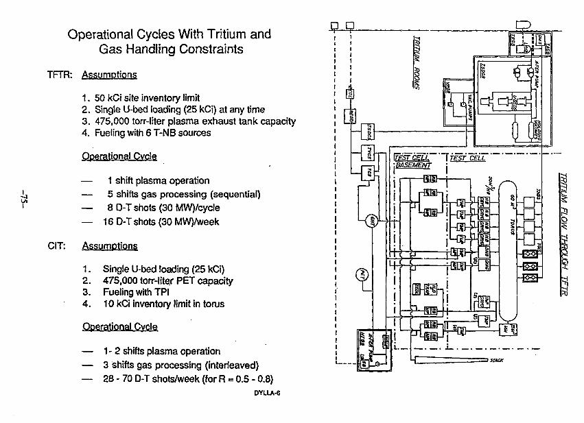
Operational Cycles With Tritium andGas Handling Constraints
TFTR: Assumptions
1. 50 kCi site inventory limit2. Single U-bed loading (25 kCi) at any time3. 475,000 torr-liter plasma exhaust tank capacity4. Fueling with 6 T-NB sources
Operational Cycle
— 1 shift plasma operation— 5 shifts gas processing (sequential)— 8 D-T shots (30 MW)/cycle— 16 D-T shots (30 MW)/week
CIT: Assumptions
1. Single U-bed loading (25 kCi)2. 475,000 torr-liter PET capacity3. Fueling with TPI4. 10 kCi inventory limit in torus
Operational Cycle
— 1-2 shifts plasma operation— 3 shifts gas processing (interleaved)— 28-70 D-T shots/week (for R - 0.5 - 0.8)
DYLLA-6
FESTCELL "liesf CELL-.BASEMENT
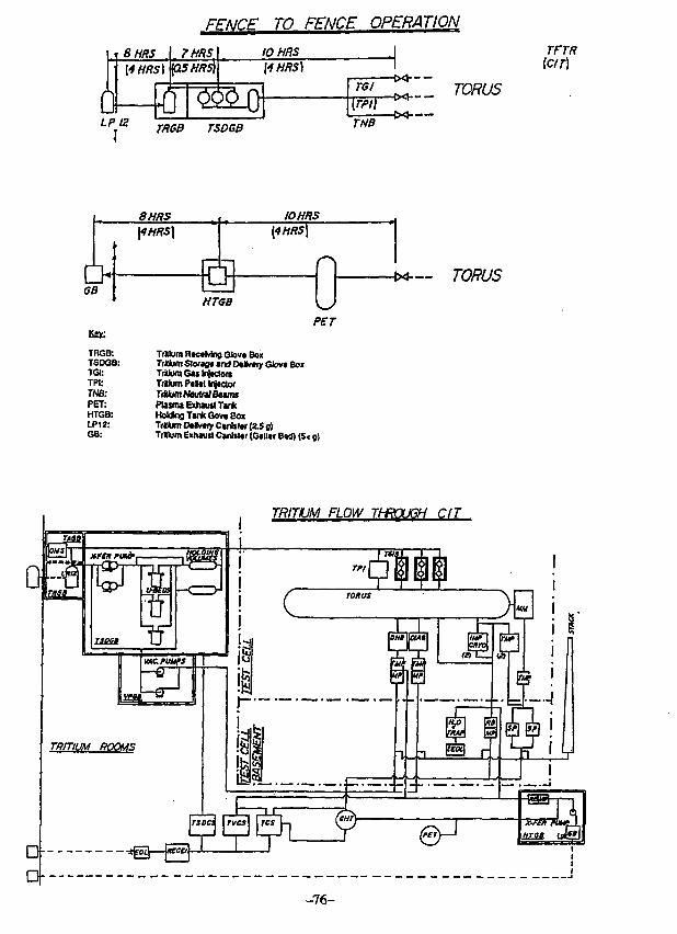
FENCE TO FENCE OPERATION
Pi0LP
1
8HRS[4HR-.
12
1 7HRSy| p5HR$\
iTRGB
VVV \JTSDGB
IOHRS\4HRS)
TGI\rpi)TNB
TORUS
TFTR[CIT]
6B
Key;
TRGB:TSDGB:TGI:TPI:TNB:PET:HTGB:LP12:GB:
8HRS\4HRS)
IOHRS[4HRS\
HTGB
PET
Tritium RtctMng Glov* BoxTrMum SUxtgt ana O*lv«iy Glov* BoxTriUumG«tni«clof$Tr»lumP*MH(ii«aofTriiiufflNeuinlBeimsPlasmi Exhaust TankHolding T«nkGov« BoxTrtlum D*lv«iy Canbtor (2.5 o)TrMuin Exhaust Canlsttr (Gtlltr B*d) (S< g)
TRITIUM FLOW THROUGH C/T
-76-
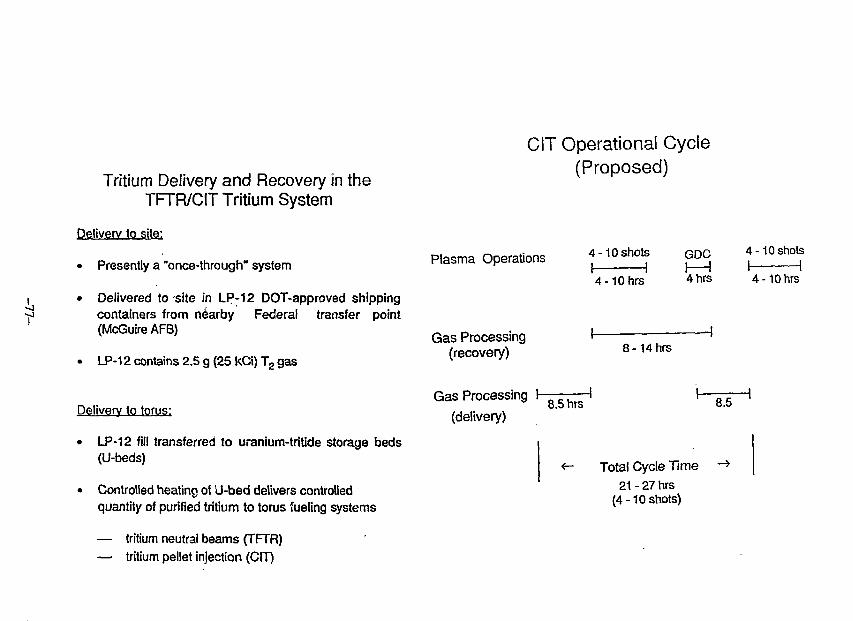
Tritium Delivery and Recovery in theTFTR/CIT Tritium System
Delivery to site:
• Presently a "once-through" system
• Delivered to site in LP-12 DOT-approved shippingcontainers from nearby Federal transfer point(McGuire AFB)
• LP-12 contains 2.5 g (25 kCi) T2 gas
Delivery to torus:
• LP-12 fill transferred to uranium-tritide storage beds(U-beds)
• Controlled heating of U-bed delivers controlledquantity of purified tritium to torus fueling systems
— tritium neutral beams (TFTR)— tritium pellet injection (CIT)
CIT Operational Cycle(Proposed)
Plasma Operations
Gas Processing(recovery)
4-10 shots GDC 4-10 shots
Gas Processing
(delivery)
4-10 hrs 4 hrs 4-10hrs
8 -14 hrs
8.5 hrs 8.5
<- Total Cycle Time ->21 - 27 hrs
(4-10 shots)
Jo
f
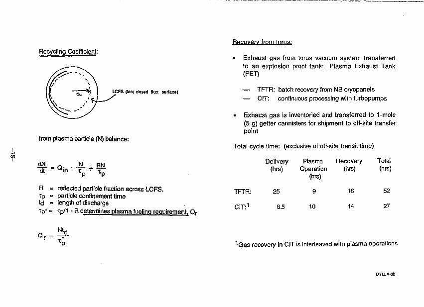
Recycling Coefficient:
LCFS (last closed flux surface)
from plasma particle (N) balance:
dt
RTptd
N
reflected particle fraction across LCFS.particle confinement timelength of dischargetp/1 - R determines plasma fueling requirement. Qr
Recovery from torus:
• Exhaust gas from torus vacuum system transferredto an explosion proof tank: Plasma Exhaust Tank(PET)
— TFTR: batch recovery from NB cryopanels— CIT: continuous processing with turbopumps
• Exhaust gas is inventoried and transferred to 1-mole(5 g) getter cannisters for shipment to off-site transferpoint
Total cycle time: (exclusive of off-site transit time)
Delivery Plasma Recovery Total(hrs) Operation (hrs) (hrs)
(his)
TFTR:
CIT:1
25
8.5
9
10
18
14
52
27
Qr = - ?1Gas recovery in CIT is interleaved with plasma operations
DYLLA-3b
RETENTION FACTOR:
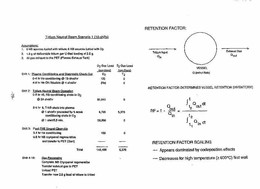
Tritium Neutral Beam Scenario 1 (10-shifts^
Assumptions:1. 6 NB sources fueled with tritium; 6 NB sources fueled with Dj.
2. 1.8 g of deliverable tritium par U-Bed loading of 2.5 g.
3. All gas exhaust to the PET (Plasma Exhaust Tank)
Shift 1: Plasma Conditioning and Diagnostic Check-Out
0-4 hr He conditioning <3> 10 shot/hr
4-8 hr He OH fiduoials @ 4 shot/hr
Shift 2: Tritium Neutral Beam Operation
C-2 hr 48, NB conditioning shots in D2
@ 24 shot/hr
2-9 hr 8, T-NB shots into plasma
@ 1 shot/hr preceded by 5 accelconditioning shots in Dg
@ 1 shot/2.5 min.
Shift 3: Post-TNB Vessel Clean-Up
0.4 hr He conditioning
0.8 hr NB cryopanel regeneration
and transfer to PET (Start)
Total
D2 Gas Load T j Gas Load
(torr-lilersl dorr-liters^D2 T 2
120 0(He) 0
80,640
6,720
58,800
120
146,400
Shift 4-10: Gas Processing
Complete NB Cryopanel regeneration
Transfer exhaust gas to PET
Unload PET
Transfer new 2.5 g load of tritium to U-bed
5.376
0
5,376
Tritium Input Exhaust Gas
Qout
VESSEL
Q (in/out Bate)
RETENTION FACTOR DETERMINES VESSEL RETENTION (INVENTORY)
RF =QoutQ:
J Qt
Q ,t2 out
dt
in
dt
RETENTION FACTOR SCALING
— Appears dominated by codeposition effects
— Decreases for high temperature (> 600°C) first wall
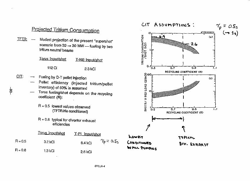
Projected Tritium Consumption
TFTR: — Modest projection of the present "supershot"scenario from 20 -»30 MW—fueling by twotritium neutral beams
C1I:
Torus Inpuf/shnt
112 Ci
T-NB Input/shr.t
2.3 kCi
— Fueling by D-T pellet injection— Pellet efficiency (injected tritium/pellet
inventory) of 50% is assumed— Torus fueling/shot depends on the recycling
coefficient (R):
R = 0.5 lowest values observed(TFTR-He conditioned)
R = 0.5
R = 0.8
R = 0.8 typical for divertor exhaustefficiencies
Torus Input/shot
3.2 kCi
1.3 kCi
T-PI Input/shot
6.4 kCi
2.6 kCi
DYLU-4
CiT
0.7 0.9RECYCLING COEFFICIENT <R>
O.7 0.9RECYCLING COEFFICIENT CR)
I.I
00
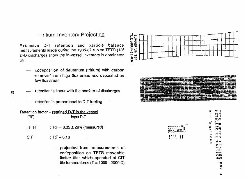
Tritium Inventory Projection
Extensive D-T retention and particle balancemeasurements made during the 1985-87 run on TFTR (104
D-D discharges show the in-vessel inventory is dominatedby:
— codeposition of deuterium (tritium) with carbonremoved'from high flux areas and deposited onlow flux areas
— retention is linear with the number of discharges
— retention is proportional to D-T fueling
Retention factor = retained D-T in the vessel(RF) input D-T
TFTR : RF = 0.35 ± 20% (measured)
CIT : RF = 0.10
— projected from measurements ofcodeposition on TFTR moveablelimiter tiles which operated at CITtile temperatures (T = 1000 - 2000 C)
> TJai m33 33
li
Him
mmKim
Il'.i II
II
0>
«Q
in
oin
pBBWtJ
3 - 1
rr n« cO S
am
o r
-{ —•—•—i
omX 7 3
CO
-c
Ol
oo
DEUTERIUM CIO17 /cm2)
Oo
| 5 ?S3S
a?»2
>
CDoo o
1 » o§ S ro2 g w
— W
CO "
51z&
1 IV4 11
•V
•
-
~ V I
#
•
o
C=
0.
111
•
\ *
ft ___F *m
\ •
\
\
\
1
D/C
=
s 9en
•L%
* \• \
- •
I 1
bW
% •
••
\
\\
f I
• #
\
\
\
i i
i i i 11
»
^ V• \
%• •
•\\ .1 N 1 1 1
SPS
o
> -ialy
s *••><•O
-
m
\ • -\ t
D-T RETENTION IN TFTR
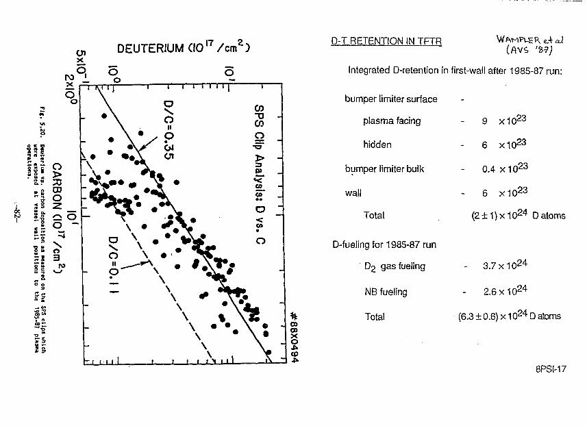
Integrated D-retention in first-wall after 1985-87 run:
%rrt38X
0494
bumper limiter surface
plasma facing
hidden
bumper limiter bulk
wall
Total
D-fueling for 1985-87 run
D2 gas fueling
NB fueling
Total
-
9 x10² 3
6 x10² 3
0.4 x10 2 3
6 x10 2 3
(2 + 1)x1024 D atoms
- 3.7 X10² 4
- 2.6 X1024
(6.3 ± 0.6) x1024D atoms
8PSI-17
oo
r
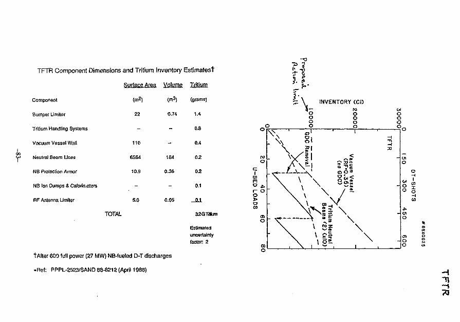
TFTR Component Dimensions and Tritium Inventory Estimatest
Surface Area Volume Tritium
Component
Bumper Limiter
Tritium Handling Systems
Vacuum Vessel Wall
Neutral Beam Lines
NB Protection Armor
NB Ion Dumps & Calorimeters
RF Antenna Limiter
TOTAL
• 3
(m2)
22
-
110
6564
10.9
-
5.0
(m3)
0.74
-
-
184
0.36
--
0.05
(grams)
1.4
0.8
0.4
0.2
0.2
0.1
_O1
32GTi*m
Estimateduncertaintyfactor 2
t After 600 full power (27 MW) NB-fueled D-T discharges
.Ref: PPPL-2523/SAND 88-8212 (April 1988)
*Vooo
INVENTORY (CD
oooo
roo
ci
CDrno *.r oo>oCO
o
oooo.
. \
** A
\
a
oRemo
\. <
\
\\
M\
\
11
1j
\\C D _ , X
» X "
, \§-1 1
I
-n
<
i l l/ ~
\ \ \1 .
1to
10'
o1018
I io"
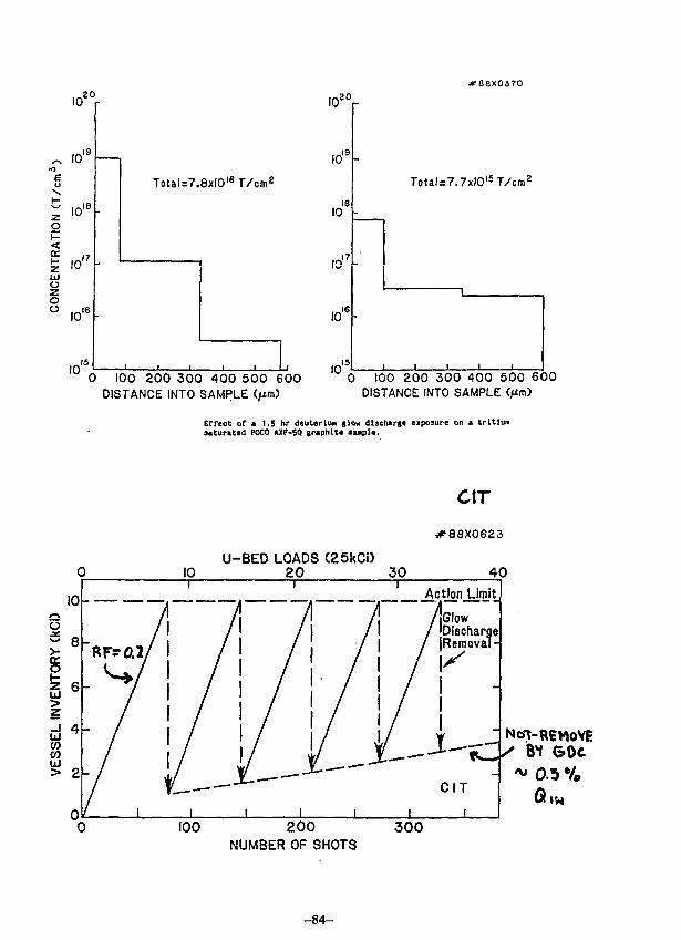
io1
10
Total=7.8xlO'sT/cm2
0 100 200 300 400 500 600DISTANCE INTO SAMPLE C/xnO
IO2Or
10'
is10
10'
1016
10'is
#88X0370
Total=7.7xlOl5T/cm2
0 100 200 300 400 500 600DISTANCE INTO SAMPLE
Effect or a l.S hr deuterium slow discharge exposure on a tritiumsaturated POCO AXF-5Q graphite sanpU.
10
10U-BED LOADS (25kCi)
20 30
ctrVT88X0623
4 0Action JJmit
Glow'DischargeiRemoval-
I100 2 0 0
NUMBER OF SHOTS300
-84-
In-Vessel Inventorv Reduction Techniques
Experiments at Sandia's Tritium Plasma Experiment(TPX) have shown 90% reduction of tritium retention intritium saturated graphite with
— 1.5 hr deuterium glow discharge exposure
Experiments on underway to optimize tritium releasefrom codeposited layers using hydrogen, deuterium, orhelium GDC
Aggressive removal methods for end-of-run
— He/5% O2 GDC (complete oxidation ofcodeposited films)
DYLLA-7
Areas of Future Studies
Optimized in-vessel inventory reduction techniques
Kinetics of tritium release / HTO conversion for airexposed graphite
Optimized operational cycles with modest tritiumrecycling loop for CIT
OYLLA-8
#88X0368
tol -OIto
06-
Idm
0.35 0.55 0.75 0.95 (.15
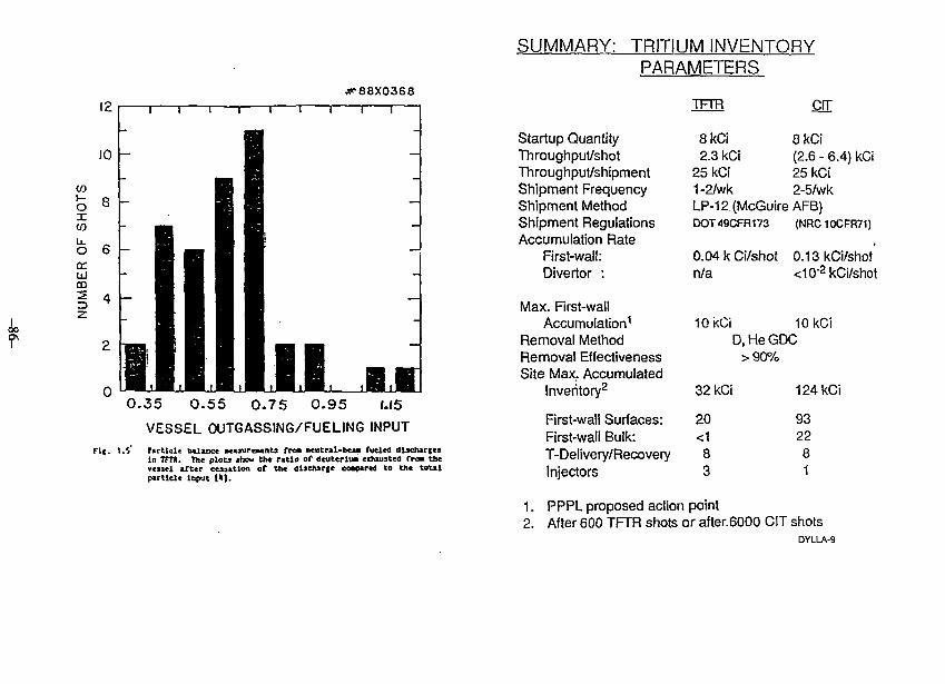
VESSEL OUTGASSING/FUELING INPUTFit. t-S" Farliele balance peaaurcaenu fraa neutral-beaa fueled i
In TfTH. Vtt plou shou tb« ratio of dcueerlua cihiuited fro« the*<3Ml tfter cuutlon of Uu dl5elur|e coapartd to the toutparticle Input (»].
SUMMARY: TRITIUM INVENTORYPARAMETERS
TFTR errStartup QuantityThroughput/shotThroughput/shipmentShipment FrequencyShipment MethodShipment RegulationsAccumulation Rate
First-wall:Divertor :
Max. First-wallAccumulation1
Removal MethodRemoval EffectivenessSite Max. Accumulated
Inventory2
First-wall Surfaces:First-wall Bulk:T-Delivery/RecoveryInjectors
8kCi2.3 kCi
25kCi1-2/wk
8kCi(2.6 - 6.4) kCi25 kCi2-5/wk
LP-12(McGuireAFB)DOT49CFR173
0.04 k Ci/shotn/a
lOkCi
(NRC10CFR71)
0.13kCi/shot<10"2kCi/shot
10kCiD, He GDC
>90%
32kCi
20<183
1. PPPL proposed action point2. After 600 TFTR shots
124kCi
932281
or after.6000 CIT shotsDYLLA-9
COMPLETE FUEL PROCESSING LOOP OPERATION
AT THE TRITIUM SYSTEMS TEST ASSEMBLY
WITH 100 GRAMS-LEVEL TRITIUM
. Hiroshi TOSHIDA, Shingo HIRATA
Japan Atomic Energy Research Institute
J.L. ANDERSON, J.R. BARTLIT
Los Alamos National Laboratory
-87-
Abstract
The joint work of TSTA (Tritium Systems Test Assembly) loop
operation started in June 1987 as a part of Japan-US cooperation
program on fusion energy research and development. During the
first year of this joint collaboration work, three major loop
operations were successfully performed. The loop operation in
June and July, 1987 were the first loop operations with 100
grams-level of tritium. The July run was a resumption of the June
run, which was halted because of a loss of cryogenic refrigerant
in the .hydrogen isotope separation system. The February-March
1988 run was the first full functional test of the fuel cleanup
system with an integrated process loop. The May-June 1988 run'was
the first loop operation in which compound cryopump was
integrated to the TSTA main process loop. Both the pumping and
regenerating performances were successfully demonstrated.
-88-
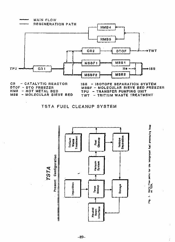
MAIN FLOWREGENERATION PATH
TPU
HMB4
HMB5
CR1
CR2
M3BF1
DTOF • T W T
MSB1
He
MSBF2 MSB2
•ISS
CR - CATALYTIC REACTOROTOF - DTO FREEZERHMB - HOT METAL BEDMSB - MOLECULAR SIEVE BED
ISS - ISOTOPE SEPARATION SYSTEMMSBF - MOLECULAR SIEVE BED FREEZERTPU - TRANSFER PUMPING UNITTWT - TRITIUM WASTE TREATMENT
TSTA FUEL CLEANUP SYSTEM
CO 5
6 , 13 M E
*~ *.
(A©
Impu
i
a
l i
.E E
sS9 >>S w
4
o .1o **
IIen
1
2 •?
i
o
Slo
ra
Neu
tral
Bea
mIn
terf
ac
e
Ii
Sc
-89-
1
aex2I•d
•sCO
HEUTIiflL BEHn RETURH
D, T —iUHc
EQUIL
CoLUnNH
He. HO. *H* , "H<URSTE
HT<H°
•i EQUIL
coLunND
DT
Te
TSTA ISOTOPE SEPARATION SYSTEM
-90-
BNLOUTRIGHT ANGLEYALVE
-TurbomolecularPiunp GAS
INJECTION
BNUNGATEVALVE
LLN1NGATE.VALVE
SiB
TRITIUMSENS5R
BUILDING VEmiLATrON DUCT
ETC
cp1
g
TORUS
CPZ
VAC• SECONDARY
ENCLOSURE
* 11 ' / I I I 111 11
General Arrangement of VACNORMAL VALVE B OPENOPERATION VALVES A & C
CLOSED
TRITIUM VALVES A &CALARM OPEN
VALVE B CLOSED
VAC Secondary Containment Schematic
Mole Sieve 5AArgon Trapping
LANL
uLLNL
Charcoal
BNL
LANL LLNL BNL
2 PH Flow LHe Reservoir
4.K Chevron 4-K Chevron 4-K Chevron
Cooling
DT Puap
DT Area
He Pu«p
He Area
0.28 m*
MS 5A
0.16 m2
0.9 m2
Ar Frost
1.1 m2
0.24 m^
Charcoal
0.13 a2
HELIUM SPEEDvs.
QUANTITY SORBED
BNL COCONUTCHARCOAL
. LLNL ARGONCRYOTRAPING
LANL MOLESIEVE 5 A
1.0 2.0 3.0 4.0 5.0SQ TORR LITERS cnr*
6.0
MAJOR TESTS AT TSTA
JUNK 1987 to JONB 1988
DATE
JOH1 1987
JOLT 1987
OCT 1987
DEC 1987
PEB-MAR1988
MAT-JUNE1988
OPERATIOI DBSCRIPTIOI
PCU/ISS LOOP 100 e-T; IMPORITI
KCO/ISS LOOP 100 g-T; IMPORITT
ISS SIVGLB COLOK*; B-D
ISS SIICLE C0L0M1; D-T
PCO/ISS LOOP BXDROGEN RECOVBRX
APR 1988 ISS
7AC/FC0/ISSLOOP
TWO COLUMJ; B-D-T
POLL FOBL LOOP
JUNE ANB JOLT 198? TRITI0H RON
- BttlHC TRITIUM INVENTORT TO 100 GRAHS
- DBMOItSTRATE IMPORITY REHOVAL DX PCO
- STRIP Hti,
• OVPLAMIIED TEST POB EMERGENCX SITOATIOK
rKBRUARX 1988 TEITIOM ROM
- STABLE OPERATIOH 0? ISS
- IMPORITI REMOVAL / 01 LINE GAS ANALXSIS
- RECOVER* OP BTSBOCEI ISOTOPES WITHON-LINE REGKKBSATXO*
- COLLECTION OF POSE TBITIOM
MAX-JUNE 1988 TRITICM R0«
- INTEGRATE VAC INTO TSTA LOOP
- DETERMINE THE PERT0BMA1CE OF VAC
OBJECTIVES OF HAI-JOME 1988 ROM
TO DEMONSTRATE THE COMPLETE PROCESS LOOP
COMPOSED OF
• VACUUM SYSTEM (VAC)
• FUEL CLEAMUP SISTEM (FCO)
« ISOTOPE SEPARATIOI SYSTEM (ISS)
• TRANSFER POMP MODOLE (TPO)
DETERMINE THE PERFORMANCE OF THE VAC
COMPOOMD CRTOPOMPS
RESULT OF HAT-JOKE 1988 TRITIUM RUN
VAC
- FIRST TRITIUM TEST
- THROUGHPUT : 2 - 10 2 OF LOOP FLOW RATE
- LITTLE IMPORITf EPPECT
- ACCEPTABLE HE/OT SEPARATION
ISS ft FCO
- REMOVE BE FROM VAC
- WITHDRAW H2, HD AID BE
- REMOVE K2
TPO
- VAC REGENERATIOK TRAI* WORKED WELL
SEC
- SMALL OFF-KORMAL TRITIUM RELEASE
ROOM
- 10 OPF-HORMAL TRITIOM RELEASE
TUT
- IM : £800 Ci
- OUT : 1 Ci
US-JAPAN Workshop onVacuum Technologies for Fusion Devices
At The Institute of Plasma Physics, Nagoya University
August 1. 1988
Presented by: S. KonishiTritium Engineering LaboratoryJapan Atomic EnergyResearch Institute
-95-
ABSTRACT
Tho Tritium Engineering Laboratory (TPL.) waaeonacruetod in the Japan Atomic Rnorgy UotsoarehInotiCute (JABRJ) . Tho objeetiveo ©£ thiu laboratoryare research and development eC the £usi@n feaeter fuelprocessing system and cafe handling technology ol largeamount of tritium. The planning of tho facility waainitiated in 1977 and the construction completed inJune, 198S. Total tritium inventory in the facility i«10 g and each experiment will be conducted with up to 1g. Teats of the subsystems in the facility in theperiod frop. 198S to 1988. Design, fabrication andinstallation o£ experimental apparatus wore conductedby early 1988. Tho first tritium was shlppod from OakRidgo National Laboratory in Fob.1988 and tho operationwith tritium initiated in March.
Major experiments with large amount o£ tritiumare; the Fuel Cleanup System that processes oiwulatedplasma exhaust, the Cryogenic distillation, of H, D, T,the Tritium parneation study with tritium ion beaa, theThermal diffusion columns, and Analysis and measurementsystem.
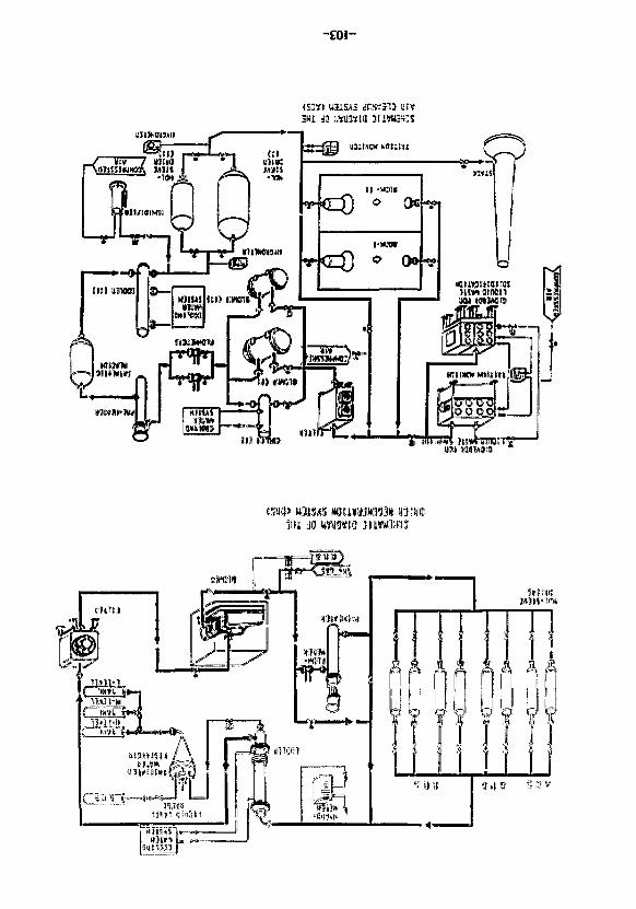
A multiple tritium confinement system is appliedin tho TPL. Tho experimental apparatus, tho glovoboxosand the airtight rooms aro respectively designed as thoprimary, secondary and tho tertiary containment. Eachcontainment has thoir main detritiation systems basedon tho catalytic oxidation - molecular siovo adsorptionprocess. The Effluent tritium Removal System (ERS)processes gas from tho primary and secondaryenclosures, and exhaust of tho Vacuum PumpingSystem (VPS). Tho Glovobox gas Purification System(GPS) circulates the nitrogen gas in tho glovebox andremoves tritium, oxygen and moisture. Tho Air CleanupSystem (ACS) can cleanup the room air in emergency. All
-96-
the molecular • sieve bods? in those dotri tiation y
can be regenerated by the Dryor Kegonora t i on
System(ORS) with circulating heated nitrogen gan.
Tritiated water in condensed and stored in tanks in the
basement.
Teats ©£' the uubsystomo In the faeility such ao
tritium removal systems, gleveboxes, vacuum pumping
syotern, tritium storage oystem have been performed in
order to evaluate and test the function, to search and
modify any possible troubles, and to havo experiences
on operation of the facility.
Tightness of the glovoboxon aro moacured by
various ways and some off-normal operations such as
break, of a glove wore tried. Tho glovoboxos wore
proved to bo tight as designed. Tho nogativo pressure
and ventilation wore controlled with a break on the
box, which was proved to be detected during the
operation.
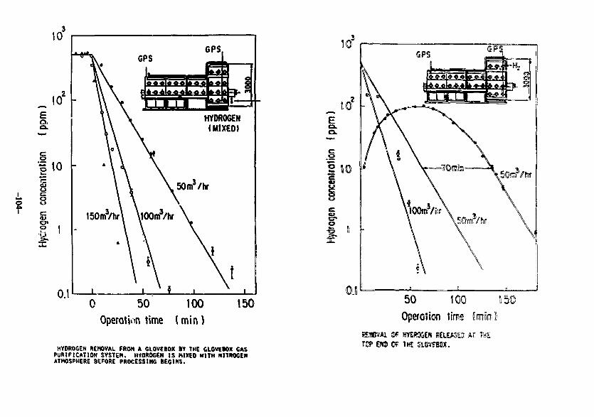
Removal o£ tritium was simulated with hydrogen
released in the gleveboxes and the airtight room. In
tha both toots, hydrogen concentration decreased
exponentially and the safety systems worked woll.
Tho vacuum pumping system in tho TFL consists of
various oil-froo vacuum pumps such an rociprocating
pump wobblo pump and turbo-molecular pump, in ordor to
prevent contamination with tritiatcd oil vapor. Tosts
havo been porformed with several combination of pumps
and gases. It is proved that both pumping speod and
ultimate pressure of oil-free pump systems with
hydrogen were much worse than with nitrogen. The
pumping characteristics of mixture of hydrogen and
nitrogen were similar to that of nitrogen. This result
indicates that pumping of hydrogen isotopes including
tritium with oil-free pumps requires special caution.
It is suggested that purging or mixing with a heavier
gas will be effective. Pumping with metal getters such
-97-
as 2rCe beds are preferable Cor evacuation o£ almost
pure hydrogen isotopes.
All cho Buboystema in the TPL facility havo boon
touted and proved to work eerroetly through the teoto
deeeribed at) above. Several meehanieal and uoCtwace
modifications were made baoed en the results and the
entire facility was now in operational with 7.Sg oC
tritium. Ten grams of tritium are purchased from the
Oak Ridge National Laboratory, and three ohipmonto have
been performed with a container with 2.Sg gaseous
tritium each.
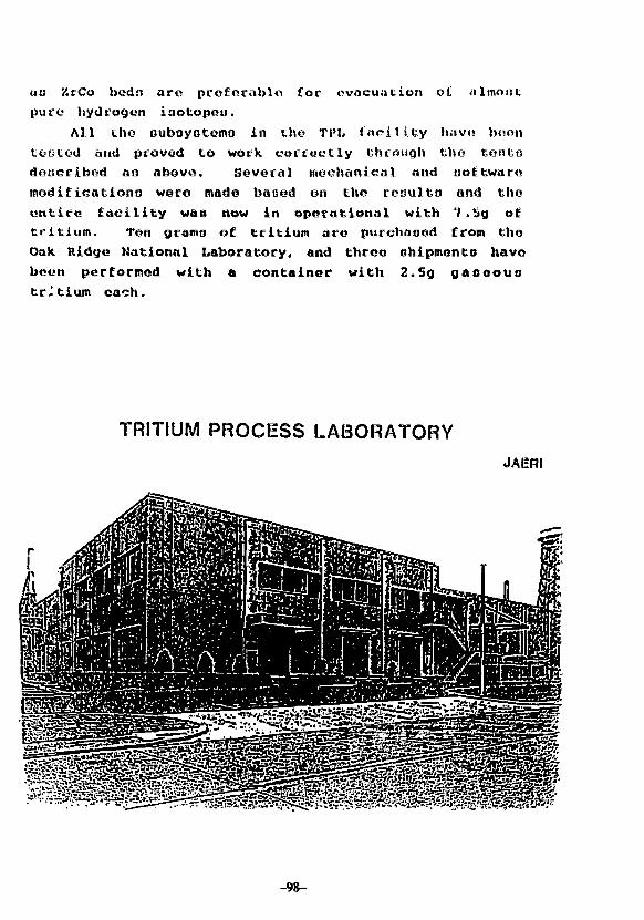
TRITIUM PROCESS LABORATORYJAISRI
-98-
ftettit
1. Objectivefttfttrefi intf <!«»*!epe««t of trftiun croctislafintf nf« Dli>4llnf ttchnaiofy far fasten ?»«l crct«
I. R 1 0 Utas(<) Fuel citlAtii
*Ptf*t1lor ntnbriA* tiffvttr
•Catltytie etl««C1«n bc<
•Ccrante «tcctr«ty*Is tt\\
•Crro?*rtU filllsf 1!«u!« f H * H* tcpartttc
(tl) Hyiraitn Uatos«
•Tdcrsit 4iff«$«en eoluJtr.( I I ! ) THttao-niStrlilt «nt«P«ette,-.J
t in< r*sa**t(») Trlttges(vl) Ulttt
(v)t) Oth
J.
•ternstrsettee
$ift
: lift -
system : 1 I I I . ESfti t i t * * ESS*
til} t*«t«tl<fif•J ««»«•* (trust iret: I«aam«, tai*f fliaer ten; IJ.J2it»:,
(Wttlttcartifre««,
•t«*tJi»iBt : W»*t*
a<Hs
: 2 -
: >C(
:*3 (Trttfen
: 2Okf*
*! Tiffin** esettlMtat iji'
esatalMcet
cts:<lt*«et
fees, wtsie
(Tl»ftsf*t« e<sfts»Sff.it*.T.i}
: Sta*tie* rest »*J
n m i t | 8? | 8
>«« *„„, ~ ~1 j *• ] ei
itt<4) Hitl tin
M . | t f l l l .totlMtutt
f»
n
6HB»1
SCHEOULt OF HH£ W l t i W I PROCESS LABORATORY.
fH }, HDFission Reactor
T,, HT, HTOUthium-based
t
T,
Isotopeseparation
D-T
Fueliniection
Fuelstorage
T,.
0 ,
Tj, D-T
HT, HOTritiumrecovery
/ materialsVHeavy water
Fusion Reactor ^ ^ 0
/^BlankerV._ ( sz
\—rv<
DT
ore) ]1Sweep-gas/
tritiumseparation
T|.HTf T,C, HTO
Fuel cleanup
T,. 0-1
Isotopeseparation
r. HT
Wastetreatment
tH7. HO
Schematic flow diagram of D-T fusion 'cactor fueirecovery sysJcm,
-100-
SUct
Schema tie of Che major aaf« system of Etic TPL facility
UFUMCIflM,
«mM*nt
CNaotMti
•tnieit
OOVitMIt
isccoNftur cmowKi
MlCUMHfsrsiw
UtSI
|cm*ui euIttlfNM MJMOML
• • ay itnttM
II1 «•'•twtiyiOHIMlitiitu
etMcratcusnrc«
IOKI
tOOM t1UIlM.IT EDO. tSMK 1
r STKK
THE TRITlUf! CONTAINNEHT SYSTEM IN THE TPL.
- 1 0 1 -
MIMIMKMNMt
MM*
I f A6MH Of UK: CM PUMFIMTIM ftStW (CPi)
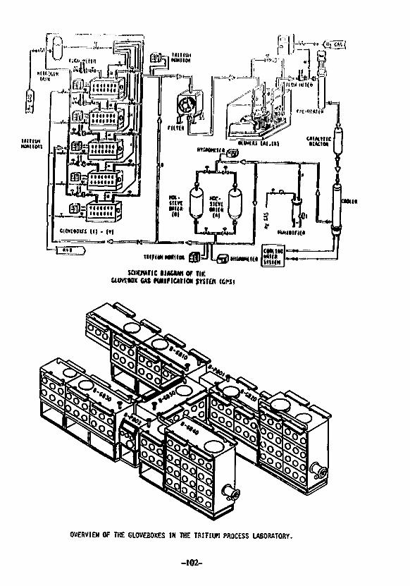
KOMt*
OVERVIEH OF THE GLOVEBOXES IN THE TRITIOH PROCESS LABORATORY.
-102-
-£01-
t$W» U3ISAS d(I»f»IJ lit*HM dB (MUKKS 3 t l W B « S
HIM 1MMM
?««»JO JUW3K35
10*
10'
o
• | 10
Io
o
0.1
GPS.
150m3/hr\ \i(3Om3/hf
0 50 100 150Operation time (min )
HYDROGEN REMOVAL FROM A GLOVEBOX BY THE CLOVEWX CASPURIFICATION SYSTEM. HYDROGEN IS NIXED MltH NlttOGENATMOSPHERE BEFORE PROCESSING BEGINS.
.oP 'nil
Of
<3
GPS
50 1C0Operoticn time
REMWAL Sf WfESSGlN RELEASED Af THE'©? O© CF Tig
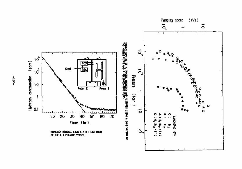
Punpfttg speed
10 20 30 40 50 60 70
Time (hr)
HYDROGEN REMOVAL F M H A AIR.TIGHT M B !BY THE AIR CLEANUP SYSTEM.
° Q or*o
o • • o
Z Z X Z SN K M M <•
• ^ o
„ 10
to
Etllmaicd
© 00 ©
« * Q Q
oo
•Evocjoltfl go:
O : !J;
o:H,:H,«7:3
; o £
* oA Q
oA O
A
ids 10Presswe (lorrl
stfcF
-106-
Suboi l l ing lo lnVern4tlon.il Syeiiosiua on Fusion Nuclear Technology
(Apr. 10-15. 1988. Tokyo),
Development o f a T r i t i u m Compat iU11? M.'IHSJ Spoct remoter
by
111 tosh I Nlyake. Ke«jl lettleura, Hasae Halsuyaaa. Kan Ashlda and
Kunlakl ttatanabe
and Shliuo Hakaaura* and Tosh I o lUyashi*
Trlt iua Research Center, Toyaaa University. Gofuku 3190, Teyaa*
910, Japan
tULVAC Co. 2500 Haglsono. Chigasakl. KtnaetirA 253. J»p*n
AUS1BACT
Trlllut exposure fives rise to considerable Increase In the noise
of *iss spectrometer. T> tvold this iapalraent and apply the B U S spec-
trcecter to D-T burnlne fusion devices, *e developed i trltlui compati-
ble ^uidftipole aati tpectroaeter *llh trlliui de€f<nUiln4tlon devices.
It wi» obierved th»t the so lie level and width Increased with Irk
tins exposure: ftaaely, the noise level Increased to 100 Uses of the
Initial one ovine to A cumulative trltUm exposure of 0.1 Torr«sec. The
Increase In the noise width, on the other hand, was about 30 Uses. It
«as confirmed that the Increase la the noises Is due to the triUue ad-
sorbed on the surfaces of Inner wall of the vacuum system, «,uadr«pole
and detector Itself: the tritium la e*s phase played only a minor role.
Tttt noise level and width could not be effectively reduced by staple
evacuation at room temperature. On the other hand. It was revealed tin!
photon Irradiation by halocen Itap caused to reduce both of the noise
level and width. The photon Irradiation by aercury laap acted similarly.
The decontamination (I.e. removal of the adsorbed trltluo) is not due to
theraal effect but to photon Induced desorptlon. Those results indicate
that the tritiua contamination of the mass spectroaeler can be removed
in-situ by photon irradiation, althoueh the improvement of the pumping
system and photon Irradiation device should be required.
-107-
P«ik currcnt/A
Noiw Cilrrflnt/A
-108-
H I ) / l i t ) i l i n e ) i t < I
I D * > i • « i « o t )
m i i m i ) « « • ) ) * • )
I r - v . r tC t i t c r
"CryetcnIc rune' * I«rt>oao1 t c u l o r
fuae"Stv i t t r Ion r««i> f I tut e / c r b l i . u n i t
I * t*« «.»nd<i r*t#
-109-
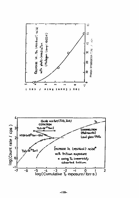
ise*Increase in Cresrduoi) ncise
l exposure
* owirg To ir
-7 -6 -5 -4 -3 -2 -1 0 I 2log (Cumulative T2 exposure/Torr s )
-no-
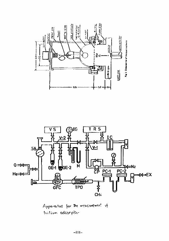
CH4
TVe
-ill-
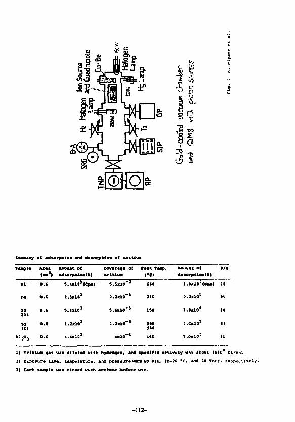
14£ J
a a Q
313
SuMury of *d»orpcloi\ jnd 4««orptton of t r l t t i a
Mi
r«
ss304
SS(E!
AljO,
Ar«a
O.C
O.C
o.c
o.t
o.c
Amount of
S.UlO*(dpai|
1.U101
• • • • " '
Covaraqa ofU-ltlua
S.S«10"J
J.IxlO*5
S.C«IO"*
l. I«10"S
4«10'*
r«ak Tamp.
<#CI
:co
aio
ISO
1*0s«o
ICO
Amtsufit o f
l.Oclo'Cdpal
7.I.10*
l.C«10S
i.e.JO'
11
u
• 1
11
1) TritiuM fas vas diluted with hydroa.cn, and epveifs« activity vas about 1x30 C:/D-.1 .
2) Cxpo*ura t l M . tcapcratur*. and ptcaiura w n CO ain, JO-}* *C. and 19 Terr. r«bpeciiv«ly.
3) Each »inpl« wa* rinicd with ac«ton« b*for« use.
-112-
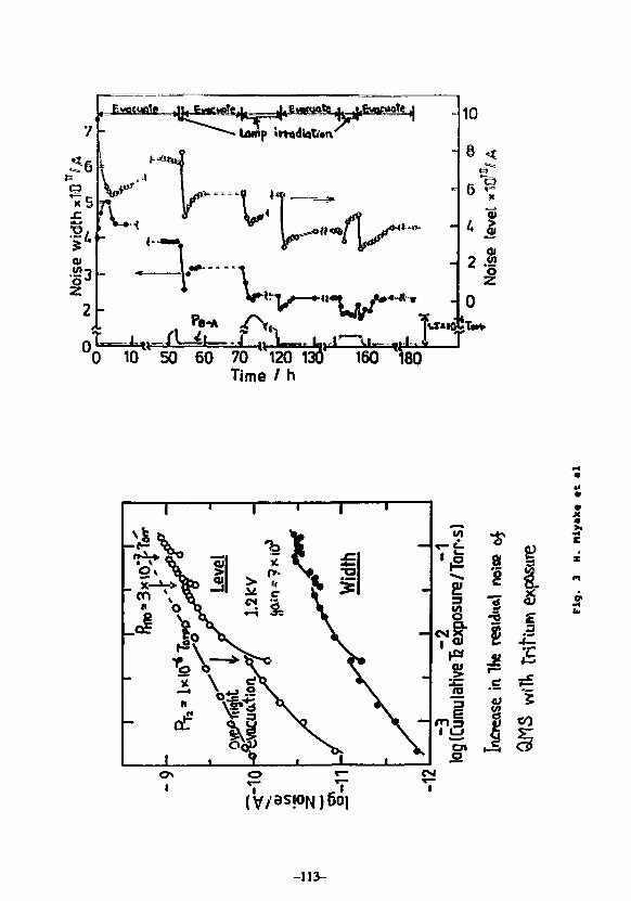
7
©
* 3
Ewatuntg
Ump i
<"«ti«
^
P.-* / V
» « *
1 I°0 10 50 60 70 l120 13^'' 160 ^80
Time / h
©
IVI
1
(V/as!°N)6oi
-113-
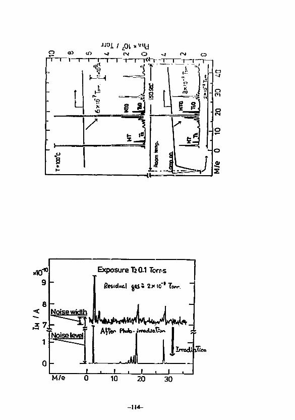
Exposure T2 0.1 Torr-s
icn
M/e
-114-
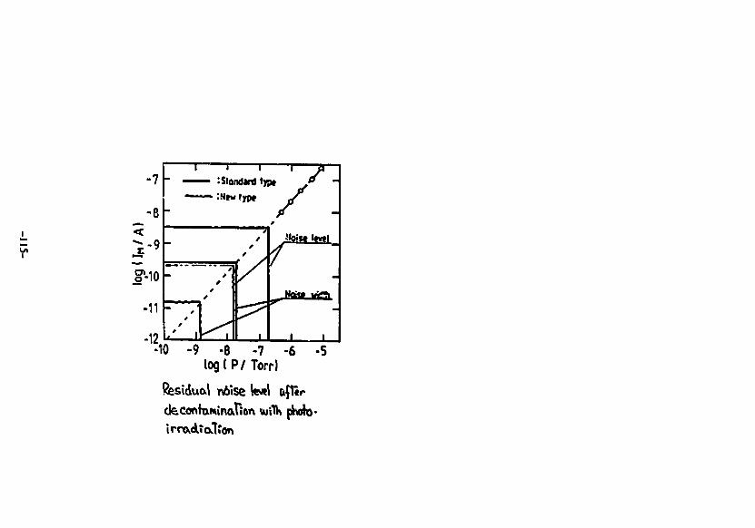
-7
-eh.-9h
-11F
-12
1 I 1
- — — : Standard f»|
-
/ 1
tf
//
//
' /
/
1 </*
" / -
HOiMlCirtl
1 1
-10 -9 -8 -7 -6 -5logtP/Torrl
inaTion luflk pkio-irrovdTatfen
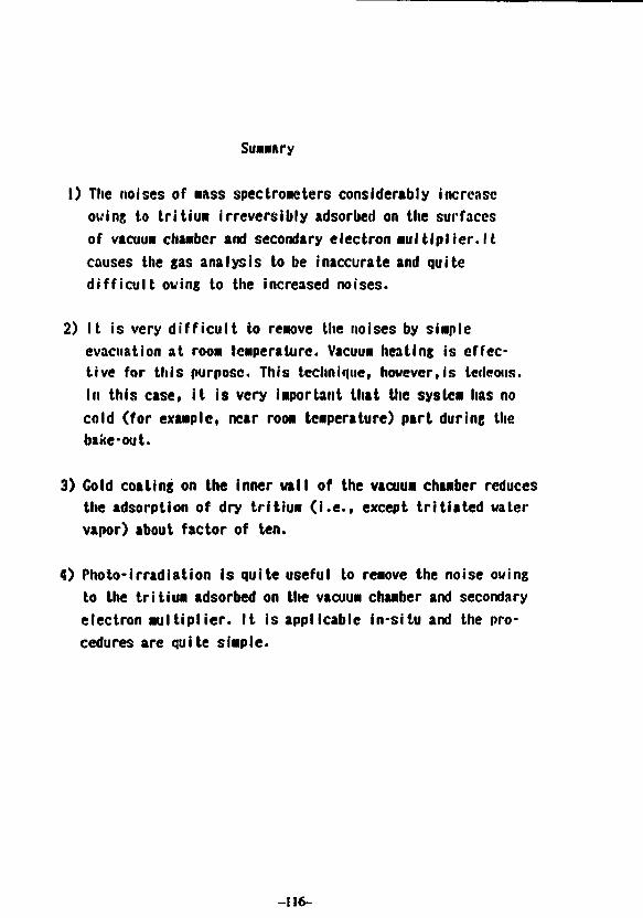
Summary
I) The noises of M A S S spectrometers considerably increaseowing to tritium irreversibly adsorbed on the surfacesof vacuum chamber and secondary electron multiplier.ltcauses the gas analysis to be inaccurate and quitedifficult owing to the increased noises.
2) It is very difficult to remove the noises by simpleevacuation at room temperature. Vacuum heating is effec-tive for this purpose. This technique, however,is ledeous.In this case, it is very important that the system has nocold (for example, near room temperature) part during thebake-out.
3) Gold coating on the inner wall of the vacuum chamber reducesthe adsorption of dry tritium (i.e., except tritiated watervapor) about factor of ten.
4) Photo-irradiation is quite useful to remove the noise owingto the tritium adsorbed on the vacuum chamber and secondaryelectron multiplier. It is applicable in-situ and the pro-cedures are quite simple.
-116-
OUTGASSn^lG MECHANISMS FROM THESURFACE
AND THE BULK
G.HORKOSHIKEK- NATIONAL LABORATORY FOR HIGH
ENERGY PHYSICS
-117-
The oulgassing phenomena from a solid surface isone of (he most important phenomenon in vacuumtechnique. This phenomena can be divided into uvoprocesses. One is the desorption of gas moleculeswhich is adsorbed on the solid surface ant the other isthe one being accompanied by a diffusion processfrom inside of the solid. Gas atoms dissolving in thesolid diffuse towards the surface layer where atoniesmigrate, encounter and rccombine to form gasmolecules most of which will desorb from the surface.But, if we try to understand outgassing phenomena asa desorption process or a desorption accompanied bya diffusion process, we find some discrepanciesbetween the theory and practical outgassingphenomena. In this report, we consider two kinds ofprocess of outgastsing , point out Hie maindiscrepancies between the theory and practical dataand finally suggest an advanced conception.
-118-
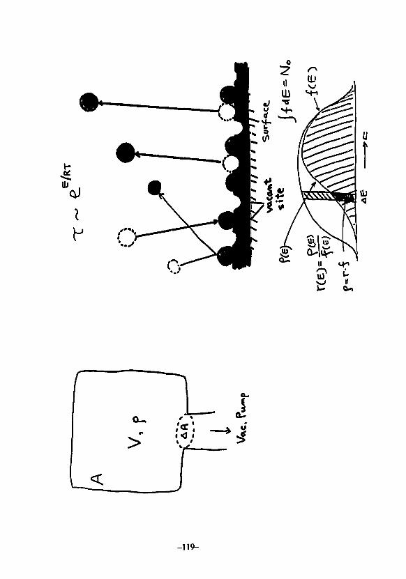
-119-
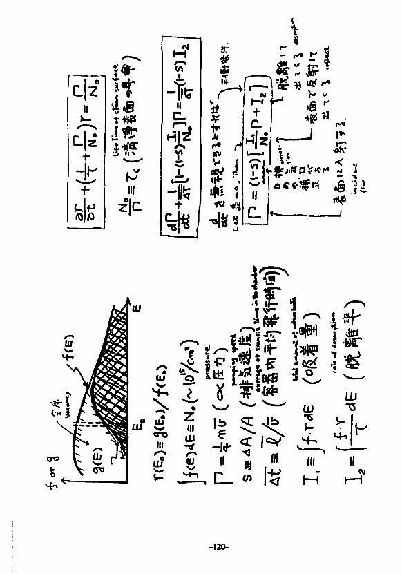
II)*.
±
I*isJ *
III
z|c
CT1
- I I " ?II
cHTZ?
r
V*
to
- IS
i0i
hH4-1
c.1 •H|Z
Ij
- r* ^ I
^ ^
n i— i
^ j
TOf»
cr©
tu
uf £III
U?
-120-
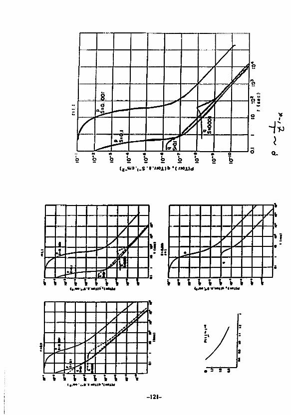
id
— — i •
— —
— —
/
/
/
/
b b b 'o b
%
Ia.
ft \
1•t.
«-t \
»»»»
[ !
M M
•!'«••
\ \
/k
1
Hi. ****
0
f
/
r
r
\ \ \ \ k k i
i
.—1
<\ 4
/'/
//
1
, ;y
\
•yk
fc
1
k
33 S 3
I •.»•-«.•'•'•»*!»'laai
-121-
If
Vl
o
o
II
6H
100
o
Ow If
r
"o
«
o
o
2
-I
-122-
i a
^ 2
.1 £K
0
k4f
3
*=
1
i
1i
e • • •' • " * »
e 3 b ib bX X K X Xn 0 it n »
ri ^ « « U
s a s ts s« e « ti
w • •A A - ° A• • *^ «^ «
o a k t. a
e n
. H
b b2 2<4 m
• *
» «
— t^
a a
UX Xo q
** s
•* *h k«• n
•iO*H(Twrl
t
1
^ *
0
lICT'Wrf
10 2Ot f««c»
90
-123-
ITER VACUUM PUMPING SYSTEM
PRESENTED BYJ. R. HAINES
FUSION ENGINEERING DESIGN CENTER/MCDONNELL DOUGLASAT THE
U.S.-JAPAN WORKSHOP ON VACUUM TECHNOLOGIES IN FUSION DEVICESIPP - NAGOYA UNIVERSITY
AUGUST 2, 1988
-124-
ABSTRACT
ITER VACUUM PUMPIMO SYSTEM
J. R. Mai ties
Providing the required vacuum conditions and adequateimpurity removal fron the plasma chamber is crucial to thesuccessful operation of the International ThermonuclearExperimental Reactor (ITER). Recent U.S. efforts on ITER-likodevices such as TIBER have examined several design approaches tothe vacuum pumping system.
For the compact TIBER configuration, which has a fusionpower of only about 300 MW, it is possible to design a tritiumcompatible vacuum system which is all-metal and operates in athroughput, as opponod to hold-up, fashion using existingcommercial equipment. Removal of the plasma exhaust during thefusion burn period is the most stringent performance requirementfor this system which has a net D-T pumping speed of 25 m3/s.The TIBER vacuum system design includes 32-turbomolecular pumpswhich are backed by oil-free, mechanical scroll pumps.
Although the ITER vacuum system requirements are not yetfully defined, it appears that the required net pumping speedwill be much greater than for TIBER. The TIBER vacuum systemdesign cannot be simply scaled up to a device with a fusion powerin the range of 1000 MM since a prohibitively large number oftubomolecular pumps would be required. Therefore, efforts arerequired to develop hi-speed, rcgenerablc, compound cryopumps andlarge diameter, all-metal, high vacuum valves for ITER.
-125-
ITER VACUUM SYSTEM REQUIREMENTS ARE NOT YET WiLL DEFINED
• RECENT EFFORTS ON TIBER REFLECT U.S. POSITION ON VACUUM SYSTEM DESIGN
• FUSION POWER AND VACUUM CHAMBER SIZE IS UKflLY TO BE SIGNIFICANTLYLARGER FOR ITER.
FUSION M« ASHPOWER (MW) REMOVAL RATE (loff- /•)
TIBER 300 3 5ITER 1.000 IS
t MAY NOT BE SIMPLY A MATTER OF SCALING UP THE TIBER DESIGN
VACUUM PUMPING REQUIREMENTS
INITIAL PUMPOOWN
• BASE PRESSURE REQUIRED• OUTGASSING RATE• SURFACE AREA FOR OUTGASSING
PUMPDOWN BETWEEN BURNS (PULSED DEVICE)
• CHAMBER PRESSURE REQUIRED JEFORE BURN• CHAMBER PRESSURE AFTER BURN• CHAMBER VOLUME
• DWELL TIME BETWEEN BURNS
IMPURITY REMOVAL
• FUSION POWER• HEUUM FRACTION IN DIVERTOR CHAMBER
• NEUTRAL PRESSURE IN OWERTOR CHAMBER
REMOVAL OF DT AT (FUELING - BURN) RATE
• FUELING RATE
-126-
TORUS VACUUM SYSTEM REQUIREMENTS
• PUMPOOWN TO BASE PRESSURE LESS THAN 10* TORR
PUMPOOWN BETWEEN CONSECUTIVE BURNS IN LESS THAN 30 SECONOS
HEUUM ASH REMOVAL RATE OF 3.S TORRL/s (300 MW FUSION POWER)
• REMOVAL OF D-T AT FUELING RATE OF 31 TORR-L/s
- 127 -
TORUS VACUUM SYSTEM (EQUIPMENT
NUMBER OF HI-VACUUM DUCTS
NUMBfR OF HI'VACUUM PUMPS
TYPE OF HI-VACUUM PUMPS
32
32
5,000 U i
TURBOMOLECUUR PUMPS
NUMBER OF ROUGHING/BACKING. PUMPS 8
TYPE OF ROUGHING PUMPS «00 nfllH
NORMETEX SCROLL PUMPS
-128-
PUMPDOWN TIME IS DETERMINED BY WAU CONDITIONING REQUIREMENTS
PUMPDOWN FROM ATMOSPHERIC PRESSURE TO 10* TORR IS VERY QUICK
• LESS THAN ONE HOUR
• CONDITIONING (#* . 8AKEOUT, DISCHARGE CLEANING) TIMES WILL BESIGNIFICANTLY LONGER ~OAYS
PtASMA CHAMBER PUMTOOWN TO 1 0 * T O M 18 EXPf CTEO
• BASE PRESSURE LIMITED BY OOTGASSING
OUTGASSINO ASSUMPTIONS
• STAINLESS STEEL• AREA (m*) 900• RATE (tofr-Lfc-m*)• COMPOSITION (H2/N2)
• GRAPHITE• AREA (M2) 100• RATE (tarK/a-m2)• COMPOSITION (H2/M2)
NET PUMPING SPEED #L/«1
• FORH2• FORN2
BASE PRESSURE ITORRI
• H 2
• N2• TOTAL
S X 10-^046/0.14
SX10-*0A2ft.1l
38.00012,000
4.4 x 10*92.2 X 1 0 *6.6 x 10-9
-129-
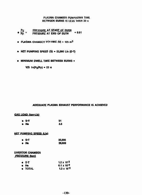
PLASMA CHAMBER PUMPOOWN TIMEBETWEEN BURNS IS LESS THAN 30 s
P§ PBESSUBE AUSTAQT-Qg BURN• Pp E PHGSSUHE AT END OF BURN H ° 0 1
• PLASMA CHAMSCR VQIUME (V) * 12S n»3
• NET PUMPING SPEEO (S) - 25,000 L/i (O-T)
• MINIMUM DWELL TIME BETWEEN BURNS •
V/S 1n(Ps/PF) - 23 •
ADEQUATE PLASMA EXHAUST PERFORMANCE IS ACHIEVED
GAS LOAD (tonAJti
• O-T• Ht
NET PUMPING SPEED (U%)
• D-T• He
DIVERTOR CHAMBERPRESSURE (Ion)
• D-T• He• TOTAL
313.5
25,00029,000
1.2 x 10-30.1 x 10*31.3 X 10-3
-J30 -
CONCLUDING REMARKS
• TIBER VACUUM PUMPING SYSTEM DESIGN IS SIMPLE
• NO MAJOR R*D REQUIRED
• HOWEVER ITER VACUUM PUMPING SYSTEM REQUIREMENTS ARE QUITECHALLENGING
• HI-SPEEO, REGENERABUE, COMPOUND CRYOPUMPS
• LARGE DIAMETER, ALLHMETAL, HIGH VACUUM VALVES
-131-
Outqassinq of Hydrogen
from Metal Wall
Michio VAMAWAKI
Nuclear Engineering Research Laboratory,
Faculty of Engineering,
University of Tokyo
-132-
Abstract
Outgassing of hydrogen gas from metal wall is
controlled either by bulk diffusion rate or by surface
recombination rate. In this respect, the recombination
coefficient k R Cor hydrogen on metallic material is
essentially important in evaluating hydrogen eulqaoeiinj,
but, so far, its database has been rather poor. In the
present study, the kR was evaluated for such metals as
stainless steel, vanadium and nickel from experimental data
of permeation rate of ion- and gas-driven hydrogen isotopes.
The measured values of k R were found to decrease with
increasing the surface concentration of certain impurity
elements; oxygen for stainless steel, sulfur for both
vanadium and nickel as was determined by Auger electron
spectroscopy. They were also compared to theoretical models
and the role of surface impurities on the hydrogen
recombination process was discussed mainly in torsi of the
activation energy of hydrogen chemisocption.
-!33-
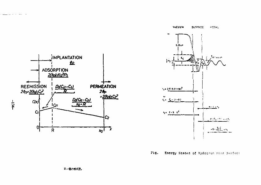
.V«CUUM
r i g . Ef««srgy StaEes of My
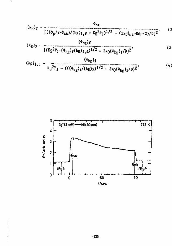
''st
[ (i
2xo(*bg)i/D)-'
_
<v• .&
5
3
2
ll
A
O2*(3keV)—=
F f, i , i
w
0. ,, . i „ ,, «
60//sec
(20
773 K-
—
—
It 1 * i
-135-
kR0(T)
Rh^so2ES - kT l n [ — — ]. (10)
1.84x10²⁰
Table 1 Summary of experimental conditions of simultaneous ion- and gat-
driven permeation of deuterium for each metal under inyeitlgation.
•etal 304 SS vanadiun nickel
relsrence [6] [7] [8Jspecimen thickness (xo[um]) 50 55 20najor surface iapuritics SitP,M,0 S S
deuteriua ions flux : 4p • •»» 10^^ D co~2 »"1deuterium gas pressure: V\ * i» 10"^ Paspecimen temperature : T - 773 X
-136-
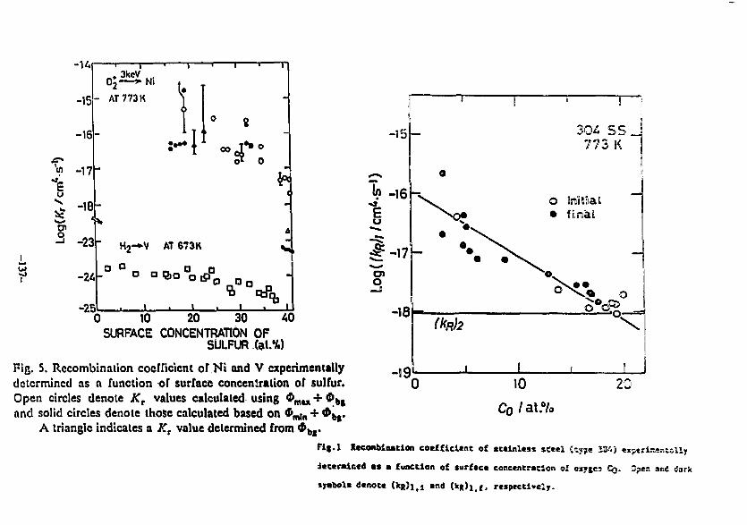
u
-15°2
- AT 773 K
Ni
-16
-17
-18
-23
-25
00
H2-»V AT 673K
a a a a
0 10 20 30 40SURFACE CONCENTRATION OF
SULFUR fel.'A)Pig. 5. Recombination coefficient of Ni and V experimentallydetermined as a function of surface concentration of sulfur.Open circles denote Kr values calculated using $ffll]t + $ b >
and solid circles denote those calculated based on $„,]„ + *brA triangle indicates a Kr value determined from $ b I .
20
Fig.l Rccoiibinacion ceeffldcnc of stainless sc«*l (cyye 20a)
Jcccrnlccd as a function of surfaca concentration of oxyjea CQ. Open and dark
sjabols dctsotc (Sqj)!^ and CkR)l.f, respectively.
1 ' . Fe1 A frJ - Ni* Si o p «>sv N o 0
(a) la = 0 h
[b) ta = 2Oh\—I—I773 K
773 K
j I I I
A 6£"/100eV
8 10
HO
\t>
-15
-20
r/ioo°c8 6_ 4 2
- Yatnawaki e t alNagasaki
1. Nickel
i I
1.0 2.0
lOOOK/r
Fig. Arrhcnius plot of recombination coefficient (hRJ
of nickel
, ^ o = TTZ|To
o o<0
E3, rt
O O
o
oPI
—• uf 2
oCM
o(£>o © d o
s
oZ
SIi!
a•a
Table 2 Results of recombination coefficient evaluated as a function of
surface impurity composition Cj: ICR >» kgO exp
metal 304 SS vanadium nickel
i (element)kR° [cvfi s" "
n [(at.%)~ M(kR)B [cn^ s-1] 4.8x10⁻¹⁹ 3.4x10⁻²°
7.1xl0-l? 7.6x10-232.1x10⁻¹
R B(kR)P S
6.5x10⁻¹⁵ 1.2x10⁻²°
1.9xl0"16
1.8X10"1
l 9
-139-
itf
0.6
0.5
0.4
0.3
0.2
0.1
o ,o«
-©-•"•
©o
O initialo final
.JO——e
o
o
J L
V 773 K
• I . L
10 20 30Cs/at.%
Fi(.3 Plot of 2Gc »|i*fl»t Cg In the cist of v«n»dium.
enen
ciu8
5
Oo.
b.
-140-
Conclusion
Recombination coefficient kjj of etoinleaa ateel, vanadium and nlckal was
evaluated by using tha raaulta of permeation moaaureacnt. The kg w«a
evaluated for both upstream- ((kp.)x) and downstresm-slde «kp.)2) surface* of
each specimen.
The values of (kg)j In relation to the surface impurity compositions
determined by ACS were Investigated. The results showed that (kg)i decreaaed
with Increasing the aurfaco concentration of certain Impurity olomenta] oxygen
fc'or stainless steel, aulfur for vanadium and nickel. Thus it became dear
chat these elaaonta wore affective in reducing tha rate of recombination whan
they wero augragatad on tha aurfaco.
Comparisons with theoretical nodal showed chat kg's obtained in thla
ntudy wore aoaiovhat closer to thoeo predicted by Pick and Sonnnnberg'a modal,
no that tha role aurfaca iapuritlaa on tha hydrogen recombination was examined
with respect to their model. Plot of 2EQ, activation energy of hydrogen
chemlaorptlon« asalnat aurfaco impurity compositions revealod that tha former
Increased as the latter was increased] the rate of adsorption or daaorption
was suppressed as tho surface became segregated by such impurities as sulfur
and oxygen, resulting in tho modification of surface with thalr strong
electronegative property.
-141-

-142-
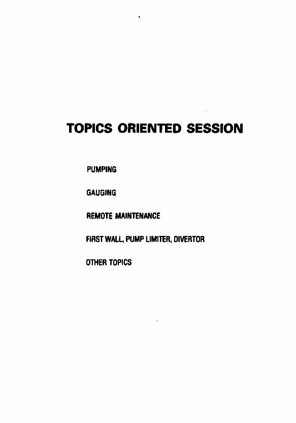
TOPICS ORIENTED SESSION
PUMPING
GAUGING
REMOTE MAINTENANCE
FIRST WALL, PUMP LIMITER, OIVERTOR
OTHER TOPICS
Jrt|jan=US Workshopon
Vaeuua Technologies for
Fusion Devices
IPP, Nagoya University
August 1-4, 1988
Development of Ceramic Turbaaolecular Puaping Systea
for Fusion Reactors
Y. Murakaai and T. Abe
Japan Atoaic Energy Research Institute (JAERI)
Naka Fusion Research Bstablishaent
Naka-aachi, Naka-gun, Ibaraki-ken. Japan
-145-
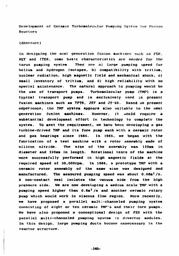
Development of Ceramic Ttirbeineleeular Pumping System for Fusion
Reactors
(Abstract)
In designing the next generation fusion aachiiics such aa PER,
NET and ITER, some baste characteristics arc needed for the
torus pumping system They are a) large pumping speed for
helium and hydrogen isotopes, b) compatibility with tritium,
nuclear radiation, high magnetic field and aechanical shock, c)
small inventory of tritium, and d) high reliability with no
special maintenance. The natural approach to pumping would be
the use of transport puaps. Turboaolecular pump (TMP) is a
typical transport puap and is exclusively used in present
fusion machines such as TFTR, JET and JT=60. Based on present
experience, the TMP system appears also suitable to the next
generation fusion machines. However, it «auld require a
substantial development effort in technology to coaplete the
systea. To meet the requirement, we have been developing a gas
turbine-drived TMP and its fore pump each with a ceramic rotor
and gas bearings since 1904. In 1905. we began with the
fabrication of a test machine with a rotor assembly made of
silicon nitride. The size of the asseably was 120am in
diaaeter and 320mm in length. Rotational tests of the aachine
were successfully performed in high magnetic fields at the
required speed of 30,000rpa. In 1986, a prototype TMP with a
ceramic rotor assembly of the same size was designed and
manufactured. The measured pumping speed was about 0.08a1 /s.
A non-contact seal isolates the vacuua side froa the high
pressure side. He are now developing a aedlum scale TMP with a
pumping speed higher than 0.8m1/s and another ceramic rotary
pump which would work in viscous flow region. More recently,
we have proposed a parallel mult .-channeled pumping systea
consisting of eight or ten ceramic FMP's and their fore puaps.
We have also proposed a conceptional design of FER with the
parallel multi—channeled pumping systea :n divertor modules.
In this design, large pumping ducts becoce unnecessary in the
reactor strueture.
-146-
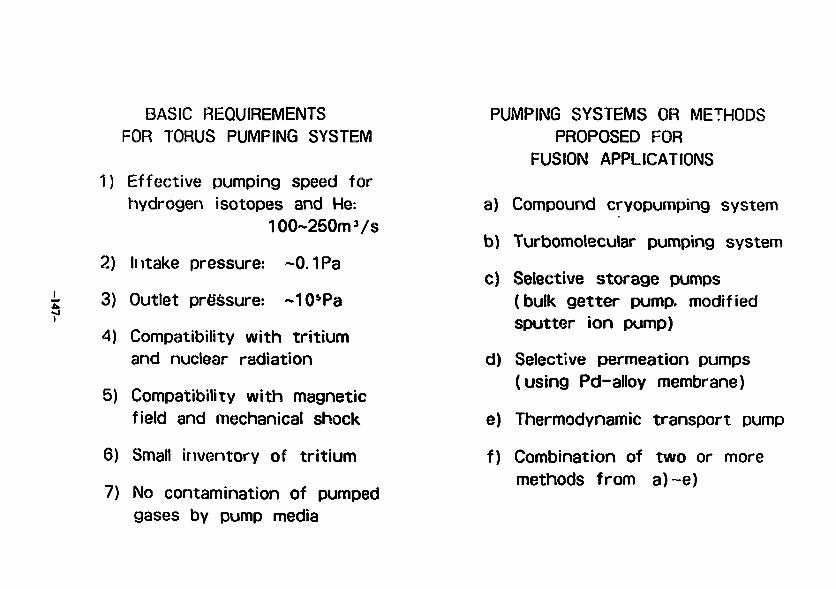
BASIC REQUIREMENTSFOR TORUS PUMPING SYSTEM
1) Effective pumping speed forhydrogen isotopes and He:
100~250m3/s
2) Intake pressure: ~0.1Pa
3) Outlet pressure: ~105Pa
4) Compatibility with tritiumand nuclear radiation
5) Compatibility with magneticfield and mechanical shock
6) Small inventory of tritium
7) No contamination of pumpedgases by pump media
PUMPING SYSTEMS OR METHODSPROPOSED FOR
FUSION APPLICATIONS
a) Compound cryopumping system
b) Turbomolecular pumping system
c) Selective storage pumps(bulk getter pump, modifiedsputter ion pump)
d) Selective permeation pumps(using Pd-alloy membrane)
e) Thermodynamic transport pump
f) Combination of two or moremethods from a)~e)
.u46
TRANSPORT PUMPS
The natural approach to pumpingwould be the use of a transportpump, which compress a gasmixture and send it through apipe to a gas processing plant
Turbomolecular pump is a typicaltransport pump and is exclusivelyused in present fusion machines.(cf. Hg and oil diffusion pumps)
The turbomolecular pumping systemappears suitable to the nextgeneration fusion machines.However, it would require a sub-stantial development effort intechnology to complete the system.
COMPARISON BETWEEN CERAMICTMP AND CONVENT 80^AL TMP
RotorMater.
DrivingMethod
Bearing
Sealmethod
CeramicTMP
Ceramics(Si3N4)
Gasturbine
Gas bear-ings
Spiralgroove
Conven-tional TMP
Aluminumalloy
Electricmotor
Ball ormagneticbearings
i Air-t ightgasket
'. • • i - • •
PL/»N AM) PHOGflESS OF TURB0MOUeCUL>fl
PUMPMG SYS1EM DEVELOPMENT A1 J*EH>
FV
.1684
1985
1086
I
1987
1988-
Ceramic IMP
PrsSmirwv »*e$tigati>aft and ptorwino |
Rotational test mamtm
(120mm*. 30.000nm)
Smal-seaht protoivpt
D U W «iin S*O<XJm'/s
1120mm*. 30.000rwt»
CURIO * i l h 5*0 8mV*
t2t0nm#. 3&000rem)
Now under c-^'wmamc* t«*t
(3&000ronl
knorovcincnt ot iMtjtuRi*Kak Ownw
Dejign study for ffwh lwr-sca*c cwnet or
pumoing sv&URK
INTAKE P€ST
COMPRESSED /GAS StJPPLY
EXHAUST
££RftMHC ROTOR
ROTORBLAOESSTATORBLAOES
NON-CONTACTSPIRAL GROOVESEAL
RADIAL/ G f e S BEARINGS
IMPULSEGAS TURBINEirausrGAS BEARING
CfIM tt&imtti vfew ef •
CERAMICTURBOMOLECULAR PUMP
CERAMICTURBO FORE PUMP(WORK IN VISCOUS FLOW REGION)
COMPRESSEDGAS SUPPLY
EXHAUST(Moim)
INTAKE PORT CONNECTING(SOI Po) OUCT
AIR TIGHTVESSEL
A unit of I t * ttrzmK !urt»-pu«tpln» > Tst*a.
MULTI-CHANNELED PUMPINGSYSTEM IN DIVERTOR MODULES
Main features:1) Large pumping ducts become
unnecessary in the reactorstructure, and duct streamingof neutrons can be small.
2) Large gate valves are notrequired
3) Tritium inventory in pumpingsystem is very small.
Problems to be solved:a) Effects of neutron irradiation
on ceramic rotor assemblyb) Effects of heat loadsc) Operational reliability and
maintenance
FEATURES OF COMPOUND CBWPUMPlfaS SYSTEM AND
CERAMIC TUR80MQn.ElCUL.AB PUMPING SYSTEM
CRYOPUMPING SYSTEM
- High punoing speed per
in i t projected area
- No imitation on eryo-
pand area
- No high-speed moving
parts
- inherently clean
- CaoaMty to separate
punped gases
- Large tritium inventory
- Cyctcai operation
- Pottmiaftv of overpres-
•urization
- Adsorbent poisoning
- Necessity of large gate
valves
- Necessity of subsequent
separation of working gas
( for AT spray method)
- Low power efficiency
TURSO PWHPJMS SYSTEM
- Higlrt omratwng speed per
unit projected area
- Transect pumping system
- Mo large gate valves
- Smat tritium inventory
— Infwentfy dean
- CapabiSty to compress
pumped gases t o to 1 atm
- Commodity with magnetic
tma mecnancai shock andnudear radiation
•- Limitaiiion on rotor
diameter
- Nccessitv of subseouent
separation ol working gas.
if any
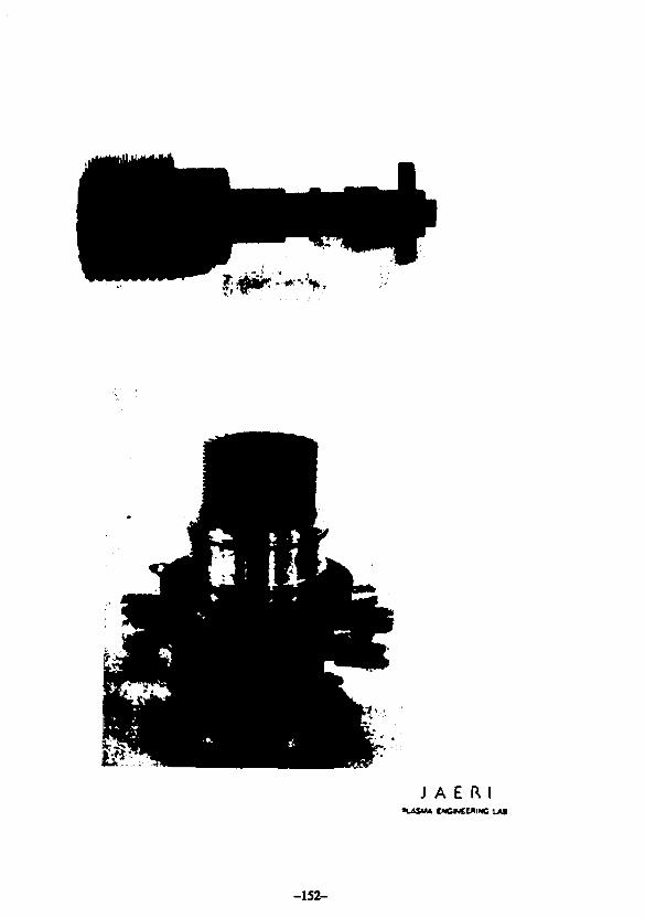
J A E f l l*uvsu*
-152-
J<i|tan • US Workshop
on
Vacuum Technologies for
Fusion Devices
IPP, Nagoya University
August 1 - 4. 1988
Per romance Test of Ceranie Rotor Turbo«oleeular Puapg
T.ABE and Y.MURAKAMI
Japan Atoaic Energy Research Institute (JAERI)
Naka Fusion Research Establishnent
Naka-aachi. Naka-gun. Ibaraki-ken. Japan
-153-
In order to develope ceramic pumps resistant to magnetic fields,
We Manufactured test ••chines consisting of a sintered silicon nitride
ceramic rotor with high electrical resistivity,oil-free gas bearings and
a gas turbine.
As a first step,the ceramic turbomoleeular pump with 80 I sec*'
(design pumping speed) was manufactured.and various performance tests
were carried out using this machine. Rotational tests of this machine
were successfully performed in both stationary (0.046 T ) and pulsed
(0.02 T/msec) magnetic fields at the rotational speed of 30,000 rpm.
The leak rate through the spiral-groove seal was Measured two
different seal gaps(25 and 50 J M ) and at various rotational speeds ( 0 -
30,000 rpm). The DUMPIng speed values which were Measured by
Mass-flow meter and orifice Methods are consistent with the design
pumping speed. The Main residual gas compositions in the test dome are
Ht.HiO.CO and CO,.
As a second step.the Integrated system which consists of ceramic
turbomolecular pump and ceramic roughing PUMP was Manufactured.
The design pumping speeds of these turbomolecular PUMP and roughing
PUMP are 800 1 sec** and 250 I min"* for Nt gas,respectively.
These experimental results have demonstrated the possibility of
new DUMPS composed of a ceraalc rotor.gas bearings.a gas turbine and a
spiral-groove seal.
-154-
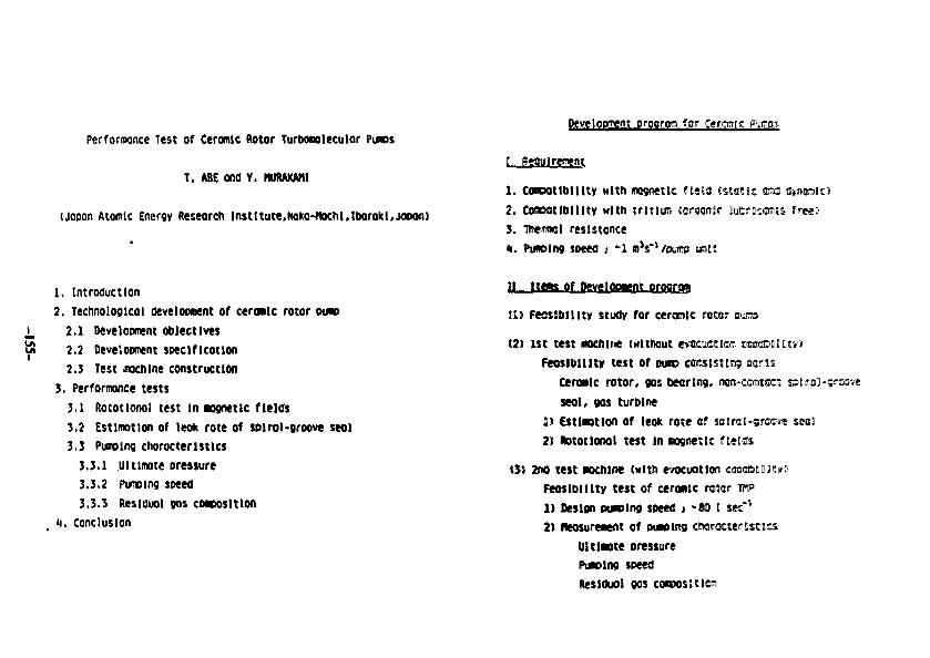
Development orccrcm fur term-KPerformance Test of Ceramic Rotor Turbotuleculor Putos
T. ABE and Y. HUftAXMU
(jaoon Atomic Energy Research lnstltute,Noko*nochl,lborakl,JOPon)
1 . ConDOtlblUty with magnetic fieitf tstaesc M
2. CosradDlllty with tritium {organic luDiMamits fresJ
3. meirml resistance
%. PtMBlng soeed i '1 n V / n i m unit
1. Introduction
2. Technological development of ceroaic rotor PUH>2.1 Development objectives2.2 Development specification2.3 Test .mcnine construction
3. Performance tests3.1 Rototlonol test In magnetic fields3.2 Estimation of leok rote of solrol-groove seal3.3 Purolng chorocterlstlcs
3.3.1 Ultimate pressure3.3.2 Pus»ing speed3.3.3 Residual 90s composition
(i. Conclusion
of IffYClMBOU
t l ) fecsiDllltv study for ceramic rotar
(2) 1st test eochii* twithout evacuee we
Feoslblllty test of PUDD consisting :cns
Ceranlc rotor, gas bearing, am-cmiest
seal, gas turbine
1) Estlnotlon of leok rote of sotrai:-5-cc<*
2) Rototlonol test in msnetlc f news
c*1
2fO test inchtne (with rAKuatlortFeoslblllty test of ceranje rotor1) Design pacing speed 1 -80 I sec*2) neasureaent of outplnc ctwractertsttcs
Ultlaote pressurePunolng speedResldool gos conoositlon
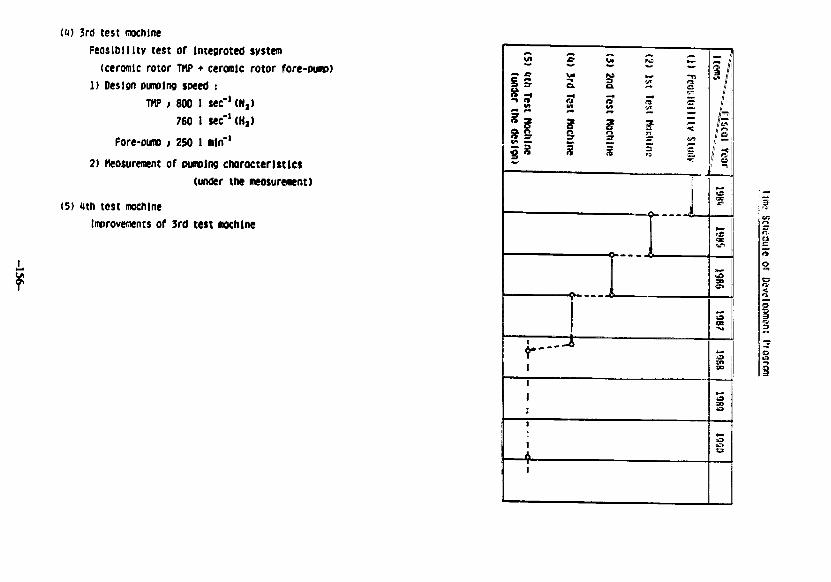
CO 3rd test machineFeasibility test of Integrated system
(ceramic rotor TMP • ceramic rotor fore-pump)1) Design pumping speed :
THP ; 800 I sec"1 <N2)760 ) sec~'(H])
Fore-pimp ; 250 I <nln"'
2) Measuremnt of pumping characteristics(under the neosurewnt)
(S) <4th test machineImprovements of 3rd test mochlne
3
«
!tiii
i
2> 3rd
trt
C*
\
i
CM ** -m
a 2 gV
?n
6 3. c
«. ,
/ft Z3
I aYear
gD
g
CO
So
r
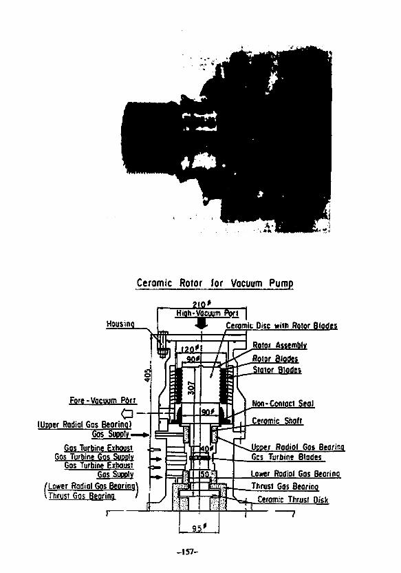
5-5
Ceromic Rotor for Vocuum Pump
Fore-Vacuum Port
a-+S(Upper Rodiol 60s Beorinq)
60s Supply-Gos Turbine Exhoust
Gos Turbine Gos SUDDIVGos Turbine Exhoust
GOSSUOPIV
/Lower Rodiol Gos Beorino1 Thrust Gos Beorino
Ceramic Disc with Rotor Blodes
Rotor AssemblyRotor Blodes
r Blodes
Won-Contact Seal
Upper Rodiol Gos BearingGos Turbine Bl
Lower Radial Gas BearingThrust Gos Beorino
Ceramic Thrust Disk
-157-
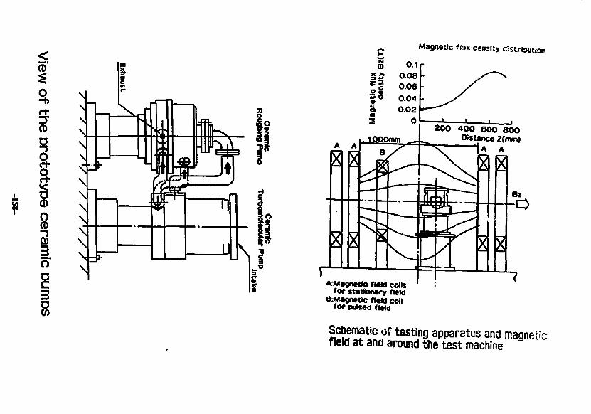
ICD
!
83
Magnetic f <M* density
£ 0.1i 0.08
= « 0.04
§ °02I O
i, 1000mm _ 4 _200 4OO 600 8OO
Distance 2{mm)A A
o e t c «ew collsfor stationary field
BrMagnetic field coilfor Dutsed field
Schematic of testing apparatus aad magneticfield at and around the test machine
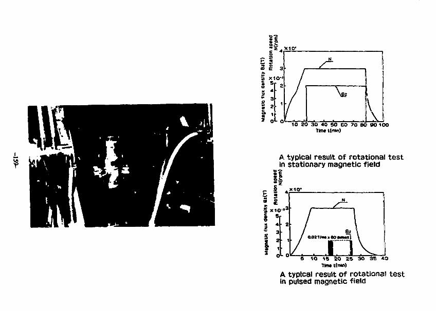
t 2
10 20 30 40 SO 6O 70 SO 90 100THte tftnto)
A typical result of rotational testin stationary magnetic field
i l
5 10 16 ZO 25 3O 3S *OTMW t(rtW))
A typical result of rotationa! testin pulsed magnetic field
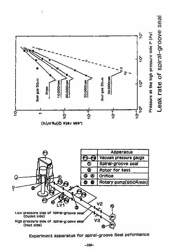
TO0CO
©©
© e
ApparatusVacuum pressure gaugeSplral-grocve sealRotor for testOrificeRotary pump(950«/mln)
Low pressure side of spiral-groove sear(Outlet side)
High pressure side of spiral-g.-oove seat*(Inlet side)
Experiment apparatus for spiral-groove Seal peformance
-160-
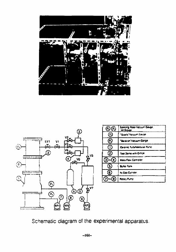
fen Dam* turn Orfiic*
Schematic diagram of the experimental apparatus.,
-161-
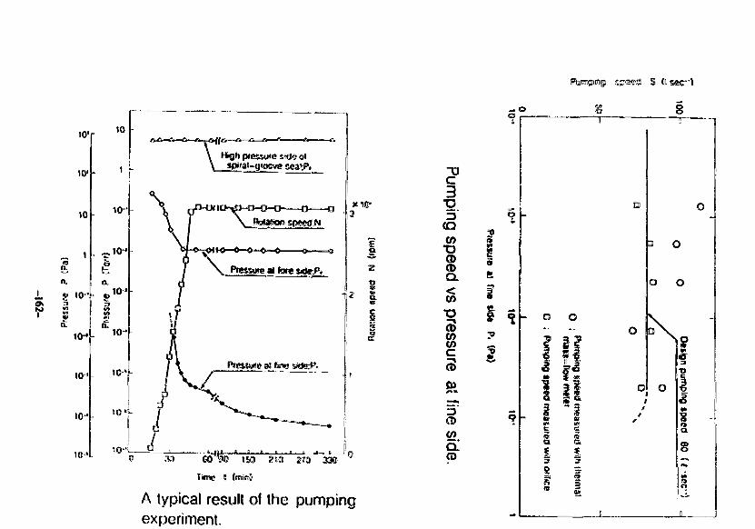
io'r
w\
10
10"
i . *> io-41 «
10**
a,
10"
1C'
104
10 '
o——oftsiasiom speed;N
Pressme M fwe vaerP,
30
3«l(Dr
Tune l tenim)
A typical result of the pumpingexperiment.
"0
*gtQ
TD(D<DQ.
to
CD(ftC
cB
CO
CL
§s
?h
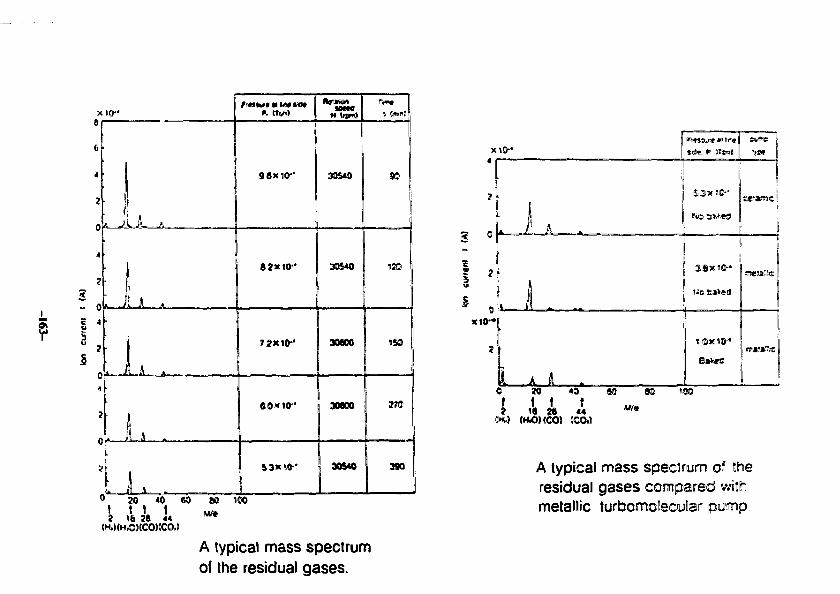
6
6
4
7
4
3- 0G 4u
04
2
1L)
• |
. i, .: I.
*. ttc«)
96X10-
82X10-
72X10^
60MH0-*
3DS40
305*0
308X
30800
M
90
.30
i n
0 JO 40 60 80 tCO\ \ \16 28 44
A typical mass spectrumof the residual gases.
20 40 SO 8©
f t I \2 18 28 **
Jut) (HO) (CO) (CO,)
"'•
A typical mass specJiruim of theresidual gases compared withmetallic turbomotecular pump.
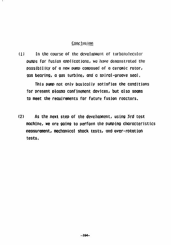
Eon£lusJ_Qfl
(1) in the course of the development of turboinoleculorpumps for fusion applications, we hove demonstrated thepossibility of a new pump composed of a ceramic rotor*gas bearing, a gas turbine, and a spiral-groove seal.
This pump not only basically satisfies the conditions
for present plasma confinement devices, but also seems
to meet the requirements for future fusion reactors.
(2) As the next step of the development, using 3rd testmachine, we are going to perform the pumping characteristicsmeasurement/ mechanical shock tests, and over-rotationtests.
-164-
INDUSTRIAL EXPERIENCE WITH MAGNETIC BEAR! N.<TURBGMQLECULAR PUMPS
JOHN K. JONESOAK RIDGE NATIONAL LABORATORY
PRESENTED ON AUGUST 2, 1988AT THE INSTITUTE OF PLASMA PHYSICS
NAGOYA UNIVERSITY
-165-
Abotract
A survey of the operational experience in the United Statesand Canada of equipment proposed to be used in the CIT vacuumsystea design is proposed. Information frea users ofMagnetic bearing turbooolecular puaps, diaphragm pumps andscroll puaps is presented. Length of tiae of puapinstallation, operational h>urs, nuaber o£ on/oCC cycles,reliability and operational difficulties are presented.Inforaation on the operational experiences with this type ofpuaping equipment in Japan is requested froa workshopdelegates.
-166-
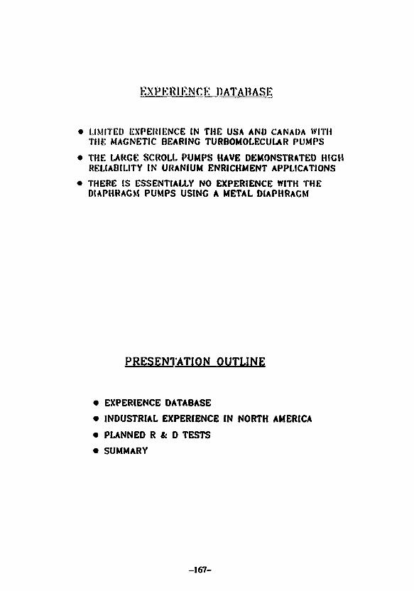
EXPERIENCE DATABASE
• LIMITED EXPERIENCE IN THE USA AND CANADA WITHTHE MAGNETIC BEARING TURBOMOLECULAR PUMPS
• THE LARGE SCROLL PUMPS HAVE DEMONSTRATED HIGHRELIABILITY IN URANIUM ENRICHMENT APPLICATIONS
• THERE: IS ESSENTIALLY NO EXPERIENCE WITH THEDIAPHRAGM PUMPS USING A METAL DIAPHRAGM
PRESENTATION OUTLINE
• EXPERIENCE DATABASE
• INDUSTRIAL EXPERIENCE IN NORTH AMERICA
• PUNNED R & D TESTS
• SUMMARY
-167-
u.Uo(A
Oo<0-)Ulao
» fe
Iu
Iff
ill*
li^liilitylj IIm.Mirinmiiimuriu'diiiininmiits'i
iinriiiiiiiniinitiimiiiiiiiuiiiHt
i u iStiiuiiiiuiiniiitii I?
IIi l l
9 8: « »<
TTiiee eooo
-168-
\A1= i
2 —- 4
* • »
-169-
E
r8
o
ii
ii I
»
H I 4
II I5 I 5 !
INDUSTRIAL EXPERIENCE IN NORTH AMERICA
• EXPERIENCE WITH SEIKO AND LEYBOLD MAGNETICBEARING TURBOMOLECUUR PUMPS
• EXPERIENCE WITH NORMETEX SCROLL PUMPS
-170-
ilH
iI
cs
a.
5
MI! i m
Ml 9
as
I
i
i!
I 3
I2
ill ii
-171-
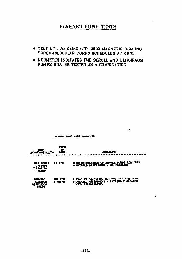
PLANNED PUMP TESTS
TEST OF TWO SEIKO 3TP-2000 MAGNETIC BEARINGTURBOMOLECULAR PUMPS SCHEDULED AT ORNL
NORMETEX INDICATES THE SCROLL AND DIAPHRAGMPUMPS WILL BE TESTED AS A COMBINATION
ccaou. WMP use* eommm
USER OfOftCANOAMItATION NHT
OAK ftlDCC »0 CfX • NO KAINKNAMCt Of SCWU. ffMK MDWtRCOOUBOOt e OVCMU. AflBUMOtr - «K> MMtCKf
oinutxoNKAMT
rAoucAN )Mcm o ru* TO MAINTAIN, WIT NOT *ei KQUJMO,CASKWt ) PWfffl e OVDUU. AUCSMDrT - dCTMEMCLV MXAJCO
otmisioN WITHKAMT
-172-
SUMMARY
• CAWING EXPERIENCE WITH MAGNETIC HEARING TUROO-MOLECUUR PUMPS, EXPERIENCE TO DATE- EXCELLENT
• EXPERIENCE WITH SCROLL PUMPS IS EXCELLENT
• NO EXPERIENCE WITH METAL DIAPHRAGM PUMPS
• TESTS ARE PUNNED TO GAIN ADDITIONAL EXPERIENCE
• WOULD LIKE (NFORMATION FROM ANY WORKSHOPDELEGATE WHO HAS EXPERIENCE WITH THESE PUMPS
M
I »
H 3
o °
5 I
I
s
-173-
New llfcliura Detection System "A-U Gauge"
August 2, 1988
By
K. Akaishi
Institute of Plasaa Physics
Nagoya University
-174-
Abstract
The A=U Gauge has been proposed t© apply for ALT=JI
pump limitec experiment if TEXTOR. An issue of tine AL¥=II
program is t@ dieeuss exhaust effieieney @f the pump iiraiter
f©r He ash. For the experiment a suitable partial pressure
gauge for helium detection is requested, boeauee tokawak
discharges will be done with the mixture gas of G* and 10%
He. The A~U qauqe has been so tar developed as a candidate
diagnostic con I for the heii»jaa detection. The operation
principle of the gauge is to use Ion backscattering technique.
A lot of demonstrative experiwents have been Made with two
ISS systems. Last year one A-U q#uge with a data acquisition
system has been constructed for TEWiOit eell&boratier* and it
is in running test for performance.
In this talk, the principle of the A-U gauge and results
of the operation test are introduced, and issues for completion
Js helium detector are discussed.
-175-
2 «1 *
3-u4
!
« !* 11
* 3£ *• 33 • t ct t " 3
a " ; s
13<o
•' • ^
V
* 4
o.
s3«
is<mco
o
IIu<K
<l>
• *
• 1
|
?241
o
s
•Ml
f•fla*
ii
3••
*U
X£
*
I••wU
10«at
it
30«
•
3t
a0
•
!
Iu «
mC
1
•
N
•
i
oc •*5. *X *
fao
c
• 5
2
xjx•
II
! :g 3 -•- 3 ge • x
g 8 83 S 5• •. oa *
3I
- *l I*• o 38 • 2- ids £
oo
S~ ^ £
i
4"
•a
1
S
O Xc a
-176-
2-7 experiment in me second its with Wl«n f i l ter
• Dining of astfiafi* gives overlapping of featured iees
peakei ef o" amd C* in energy seeetrwn. Bat tfte effect
is aiimt.
• surface eomtaniftjtion ft I to target i s eontraiied tty
in>direet »i»jt;i:-.f of ttte target fittt * h&t t l l t i w . t .
J, 2*J Construetloo ef A-
•3 • Baia aequisitiefl system i s
ttnsitivcty eaiibratiea
to t
fer
and H#*
p#rfctajftfie test of *eft «««• is under
of presturs «ie*»-i*«mn.*!i of jf* *-r s
i s ssree •}«!*? of a*|SL*B.a<l#. tfte s -prai as.-tiist i s i
Mtatatien in tfte IS* ^art, tea tft« 5aw«s 3i*.5i i s
a l t lMt i pt«Mnf« ef We Tisu'aif ty*t«f- wi*A s airal
t?» se&iill*itip drift is new
I4fif*S. teiit this f?efcl«« t* 53 li* SOilv
effect stseb as inffase .-nu'"ift
ef lncidest Son fiesn S3 •,."«! i.
l trg st«3y
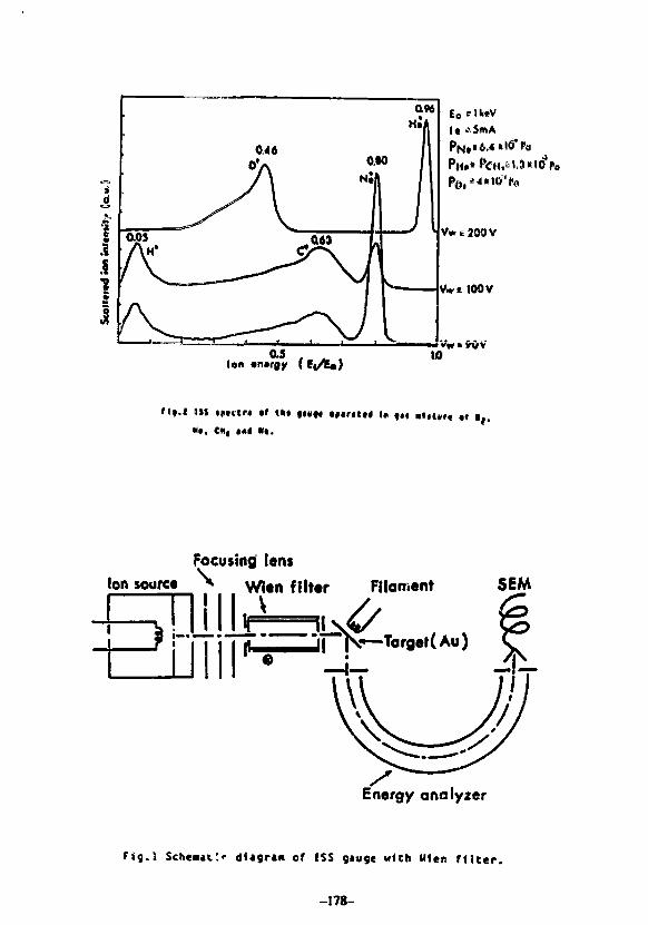
1
•8V
1
COS
AM*
O4«
' V
0.96HA
0*Nil
0
j
Ion «n»rgy (
I t .•SmA
VwtJOOV
Vwc 100 V
10
I * t f .
Focusingl lens
loft source \ Wlen filter Filament SEM
Energy analyzer
Fig.l Sche«t:<- di«9r«« of !SS gauge with Wlen n i t e r .
-178-
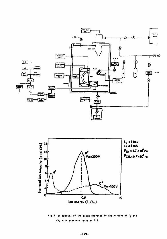
E8 s 1 k«V|«s5mA
P0|s6.7«ifl'Po
0.5Ion entrgy (Ej/Eo)
10
f l j . ) ISS tftctrt •» Ikt ft«(t •>tr«l«« to
CM4 «U«< »rt(l«r< m i l • ' 0.1.
•l<t*rt «f
-179-
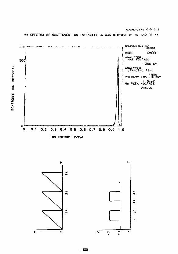
• * SPECTRA ©F SCAHfEflEQ ION INTENSITY ,N GAS MIXTURE OF M P AND 03 »•
sag
soo
. M6BE liwfifiP
oc
<u
j 3S0.0v
{ TIHE
' PRIMARY ION EINIEG
1 Ha PEEK234.0V
i
0 0 . 1 0 . 2 0 . 3 0 . 4 0 . S 0 . 6 0-7 0.9 0 , 8 4 , 0
ION g«i£ftSY (E /Eet
> « - o> >
-180-
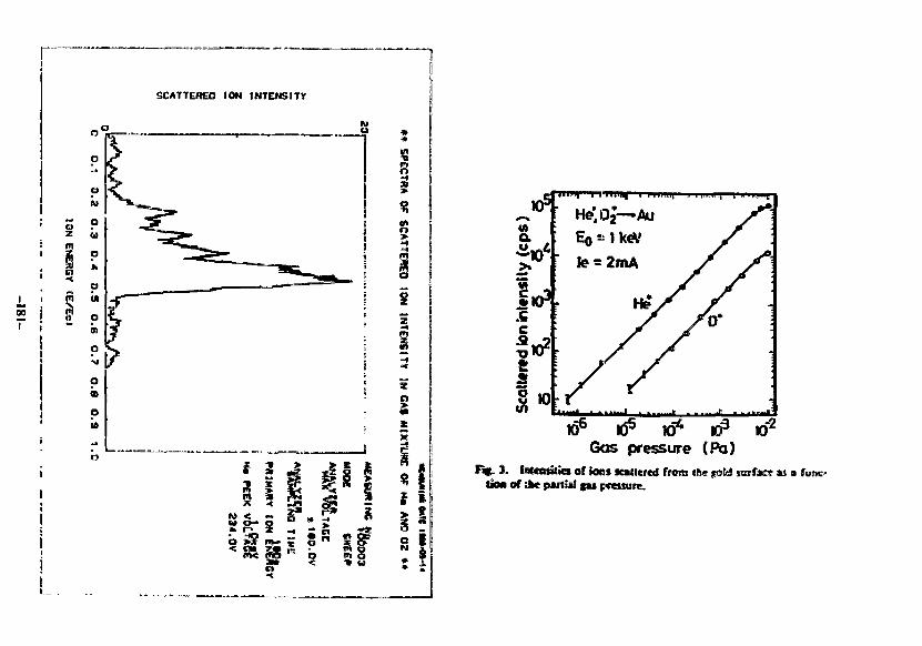
r
00
SCATTERED ION INTENSITY
s
>
z
§
u$ i
i!•I
w JQ Kj mj mj
Gas pressure (Pa)i f . 3. taensMa or ions Kattcred from the gottt wsifase K a
I > M of »e partkl gu pretsure.
Compatibility of spinning rotor gauge with tritium handling systemsTritium Kumnk GMMT, T$f*mt Unbttttf/. Otfklcu 1190, Ttym» 9X1 Jtfu
Kumalwo KarwkoI, TunuU
Yoichi Kot«ye»h(Y«*tf 441 JMtyMk* T*f /M Up*
-182-
ABSTRACT
The compatibility of the spinning rater p u p (SfiG) with tritium
systems was examined. Nitnely, the nubility at the eff-set
value of the SRC was carefully measured before and after tritium ex-
posure upto 2 x 10 Pa.4 over a period of two years, tt was found
that the off-set value was kept constant at (3.40 s 0.04) x 10"* Pa
throughout the present study. It means that there Is no measurable 8-
ray effect on ths pressure sseasuresent using SRG. in addUion, it was
also found that the absolute pressure of mixture gases including tri-
tium can be precisely measured with SRC if the relative molecular
wight of the gas, defined as ^ 1 ^ , < tt^H^ is determined with some
analytical tools such as mt%% spectrometer. Secaute of thett f*cti at
well as its simple construction, long term stability, accuracy in wide
pressure range, and potential as the absolute pressure gauge, It is
quite usefel to tritium handling systems Including thermonuclear fusion
devices as a transfer standard and/or absolute pressure gauge.
-183-
(1)
[OFS]'R •T >M >S >apCO
1 value of residual drue> c " constant : S.MxlO'OWiuol• absolute tenperature (K)• noleculer weicht> c « friction coefficient> sphere radius> specific densily «f sphere» anculc.* velocity
(1.(4.(7.
0
0243/Ar)
79 t/em'
SRC characteristics
1) Absolute pressure2) Vide ranje (10"' — W*3) Lon< tern stability (ove4) Staple construction and campaci5) No hot itarts - no
r,
Objectives of tfriiis studyt ) Effects of charje-up off mire2) Effects of the chances in
states ewins to
3) Applicablity to gas
IP OP RP
FIG. 1. Bkxk diagram of the experimental apparatus: spinning rotor gauge(SRG >, Bayaid-Alpert gauge (B-A). bulk getter pump (GP), quadrapolemass apecuometer (QMS), diaphragm gauge (DG), sputter ion pump(IP), mercury diffusion pump (DP), and oil-sealed rotary pump (RF).
-185-
3• 3\*H
3
o
3•3
s
3•3
3•3
1 * 5is
W
i§
•3
%
-186-
asT1
o h
Arbitrary unit
U— • •,- ? < • • ' • - f „ -
.: f t i
i!
- 1 . ? >
; •? *
C 5 6
5 S3
S 5 : "
i j : " : : t
" - '
i *ii«tir. t.L ".Liu
PDOIPO)
Fio. M>: M of the pfcuurt ntdovi of Iht ipiuUiii w«f (*«K H*fM( Ikeprtuuri mtuund b)r lh*<liiplin|a |«»|«: (i) foe N,, (b) fcf (H, + N,)mitltiit, tnd (e) for irilhim |U mliture.
s
8
f
8
91
•t
"B
s3
0
i
e
iuss3ife.004
e
ife§
}
f
io,01
ifo
,02
Ifo.01
If
SIo
i
9*
2
?
I & i
HiIIit» lf!A) ~
s sS. ar
» t
40
20
zo
T*—r"-
I I I I 1 I i > t
u12
0.2
0WO 4 8 12 " SO 62 66 7DTime thour)
FIG. 3. Effect of tritium exposure at room temperature on the (OFS] value:O » [OFS] value and A ~ residual pressure (N3 equivalent) measured bythe B-A gauge.
-189-
Summary
1) The [OFS] value of the spinning rotor gauge hasbeen kept constant, (3.4 ± 0.05) x 10"4 Pa, inthe present study over a period of two years inwhich the rotor has been exposed to tritium over105 Pa*sec.
This indicates that the residual drag, -(u>/(d)e,is insensitive to tritium /J-rays and hot atoms:i.e., the effects of the charge-up of the rotorand the changes in the adsorbate state are negligible.
2) It has been experimentally confirmed that the pressureof a gas mixture can be determined precisely withSRG by knowing the effective and/or relative molecularweight of the mixture gas.
3) The spinning rotor gauge is quite useful to tritiumhandling systems as a transfer standard and/or absolutepressure gauge, because of its simple construction,compact size, accuracy in wide pressure range, main-tenance free property and long term stability.
-190-
US-Japan Workshopon
Vacuum Technologies forFusion Devices
IPP, Nagoya UniversityAugust 1—4,1988
TFTR In-Vessel Maintenance
by
P. J. Heitzenroeder
Presented by: H. F. DyllaPlasma Physics LaboratoryPrinceton University
-191-
TFTR in-Vessel Maintenance
The first-wall configuration for the D-T phase of TFTR operations wasinstalled during the 1987 installation period. The in-vessel maintenancetasks that were performed during the 1987 shut-down, and similar tasksplanned for 1989 shut-down are described. These maintenance tasks areperformed hands-on by minimizing the D-D neutron activation of thevessel to the range of 1 -10 mRem/hr. During D-T operation the in-vesselradiation field (-30 R/hr) will require the use of a remote controlledmanipulator that was recently completed as a joint KfK/PPPL project. Themanipulator is presently being shipped to PPPL for testing prior toinstallation on TFTR during the 1989 shut-down period. The manipulatoris planned to be used for in-vessel inspection and removal/replacement ofbumper limiter tiles.
-192-
TFIB RESEARCH PCAM
c t u
XK f,-30»C1,-1.5 MA
ON I neVvut i V***
HT"IB—m1 I ll
•TMH4 »§tHtmt *2Nt
(••«. l ia i t t ' «•«.!. m
GcHc»•T.HOMtin-
•,-MlC
rH-su*(ol
.1 ,1
MWH.
t
1 —(—
IV.-20W
—I •r-
M H W- n»i
1 i
c r H
XCt r"-4HWX rM-2j0fCC
CU1CI*
| on
uotci
I M 0-1
-^crMie •ICHFI«W«I •r«MM
M
i
•Mmc
• K H IMIW.t
•
CTM C » l
I M
30 Kl
UM~ 1 • ! 1 1W»
•l« -|<n ' | '«H 1 W»rQM| • "^ l—JSB i•ilSit 1
•W.M
•a1
' • « • •» . HWL
ML
1N-VESSEL MAINTENANCE ON TFTR
o TFTR IS CURRENTLY OPERATING WITHDEUTvERIUM PLASMAS BUT WILL BEGINDEUTERIUM-TRITIUM OPERATION IN1991. (SCHEDULE FIG. 1)
o IN-VESSEL MAINTENANCE TO DATE HAS BEEN "HANDS-ON"- MAX. RADIATION LEVEL IN THE VESSEL
AFTER D-D RUNS HAS. TO DATE. BEEN3 mR/HR. (3 TIMES HIGHER THAN OUTSIDETHE VESSEL) THIS DECREASED TO APPROX.1.5 mR/HR. AT THE END OF THE SHUT-DOWNPERIOD.
o PERSONNEL WERE ROTATED TO LIMITEXPOSURE (PPPL GUIDELINE: <600 mR/OTR. YRTHE TYPICAL EXPOSURE DURING THE LASTMACHINE OPENING WAS < 1 0 0 m R . )( TO AN INDIVIDUAL)
-193-
TFTR CONTAINS APPROX. 2000 BUMPERLIMIT.ER TILES AND APPROX. 1000PROTECTIVE PLATE TILES. TO DATETHERE HAVE BEEN NO THERMALLY -INDUCED FAILURES. A SMALL NUMBEROF TILES « 5 } WERE REPLACEDBECAUSE OF DAMAGE DUE TOMOUNTING DIFFICULTIES.
ALL OF THE BUMPER LIMITER TILESWERE REFINISHED (SANDED) DURING THELATEST OPENING TO REMOVE HIGH-ZIMPURITIES. THE TILE SURFACESWERE CONTAMINATED BY METALLICIMPURITIES.
o Ze f f APPROX. \-Z BEFORE REFINISHING.DUE TO METALS
o Ze f f APPROX. 0 . 1 - 0 . 2 AFTER REFINISHING
PRECAUTIONS HAD TO BE TAKEN DUE TOTRITIUM PRODUCED D-D RUNS
o THE VESSEL HAD TO BE VENTEDTO ELIMINATE T 2
o THE CARBON BUMPER LIMITERS ANDPROTECTIVE PLATE TILES HAD ABSORBEDTRITIUM. BUT THIS IS WELL-BOUND.
o 50 - 100 gms . OF CARBON DUSTWAS GENERATED DUE TO SURFACEEROSION. DISPOSABLE CLOTHINGWAS USED TO PREVENT SPREADINGCONTAMINATION OUTSIDE THE TEST-CELLAND TO AVOID PERSONNELCONTAMINATION.
-194-
o IN-VESSEL MAINTENANCE DURING THE D-TPROGRAM WILL BE DONE WITH THEMAINTENANCE MANIPULATOR:
- RADIATION LEVELS INSIDE THE VACUUMVESSEL WILL BE AT 30 R/HR. 8 HRSAFTER 10 SHOTS OF 10E19 NEUTRONSPER SHOT
- TYPICAL IN-VESSEL TASKS DURINGAN OPENING:
o TILE REPLACEMENT/REMOVALo CLEANING OF QUARTZ WINDOWSo CALIBRATION OF DIAGNOSTICSo REMOVAL/ INSTALLATION OF TEST SPECIMENSo INSPECTION OF COMPONETS (ICRF
ANTENNAS. DIAGNOSTICS. ETC. . . )
-195-
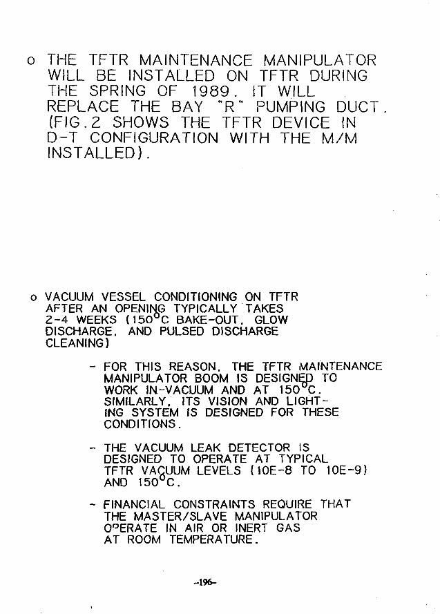
o THE TFTR MAINTENANCE MANIPULATORWILL BE INSTALLED ON TFTR DURINGTHE SPRING OF 1989. IT WILLREPLACE THE BAY "R" PUMPING DUCT(FIG. 2 SHOWS THE TFTR DEVICE IND-T CONFIGURATION WITH THE M/MINSTALLED).
o VACUUM VESSEL CONDITIONING ON TFTRAFTER AN OPENING TYPICALLY TAKES2-4 WEEKS (150°C BAKE-OUT. GLOWDISCHARGE. AND PULSED DISCHARGECLEANING)
- FOR THIS REASON, THE TFTR MAINTENANCEMANIPULATOR BOOM IS DESIGNED TOWORK IN-VACUUM AND AT 150°C.SIMILARLY. ITS VISION AND LIGHT-ING SYSTEM IS DESIGNED FOR THESECONDITIONS.
- THE VACUUM LEAK DETECTOR ISDESIGNED TO OPERATE AT TYPICALTFTR VACUUM LEVELS (10E-8 TO 10E-9}AND 150°C.
- FINANCIAL CONSTRAINTS REQUIRE THATTHE MASTER/SLAVE MANIPULATOROPERATE IN AIR OR INERT GASAT ROOM TEMPERATURE.
-196-
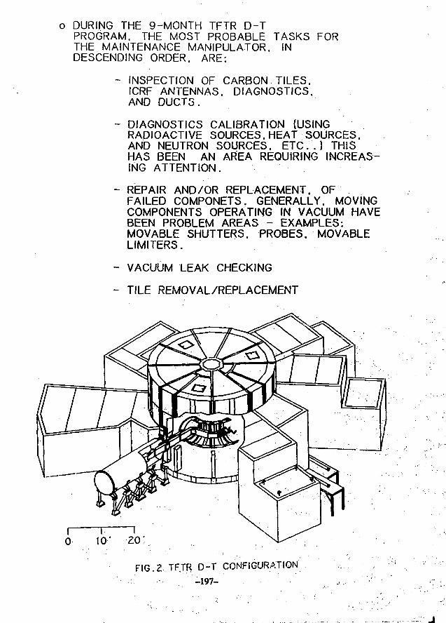
o DURING THE 9-MONTH TFTR D-TPROGRAM. THE MOST PROBABLE TASKS FORTHE MAINTENANCE MANIPULATOR. INDESCENDING ORDER. ARE;
- INSPECTION OF CARBON TILES.ICRF ANTENNAS. DIAGNOSTICS.AND DUCTS.
- DIAGNOSTICS CALIBRATION (USINGRADIOACTIVE SOURCES. HEAT SOURCES.AND NEUTRON SOURCES. ETC. . ) THISHAS BEEN AN AREA REQUIRING INCREAS-ING ATTENTION.
- REPAIR AND/OR REPLACEMENT. OFFAILED COMPONETS. GENERALLY. MOVINGCOMPONENTS OPERATING IN VACUUM HAVEBEEN PROBLEM AREAS - EXAMPLES:MOVABLE SHUTTERS. PROBES. MOVABLELIMITERS.
- VACUUM LEAK CHECKING
- TILE REMOVAL/REPLACEMENT
FIG.2 TF.TR D-T CONFIGURATION'
. • . . - • . ' ' - 1 9 7 -
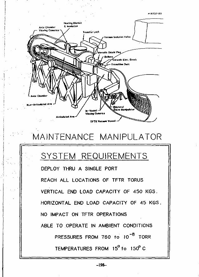
r87EOIO3
rAnU ChanterViomg Cimeril -
HtltKij BUnkct& Insolation
ArticnUtW Aria
TFTR Vacwa V«»«el -
MAINTENANCE MANIPULATOR
SYSTEM REQUIREMENTS
DEPLOY THRU A SINGLE PORT
REACH ALL LOCATIONS OF TFTR TORUS
VERTICAL END LOAD CAPACITY OF 450 KGS.
HORIZONTAL END LOAD CAPACITY OF 45 KGS.
NO IMPACT ON TFTR OPERATIONS
ABLE TO OPERATE IN AMBIENT CONDITIONS
PRESSURES FROM 760 to IO"8 TORR
TEMPERATURES FROM 15° to 150°C
-198-
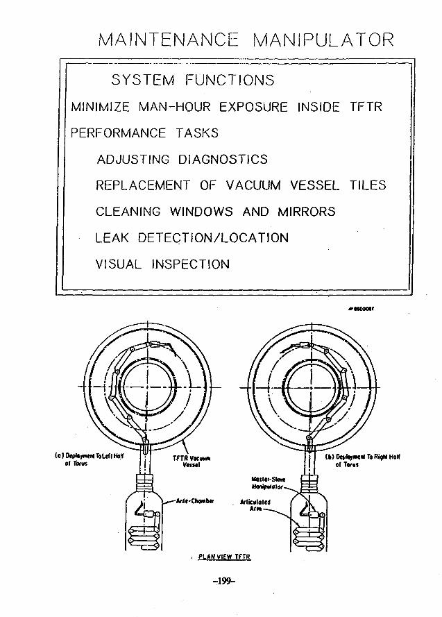
MAINTENANCE MANIPULATOR
SYSTEM FUNCTIONS
MINIMIZE MAN-HOUR EXPOSURE INSIDE TFTR
PERFORMANCE TASKS
ADJUSTING DIAGNOSTICS
REPLACEMENT OF VACUUM VESSEL TILES
CLEANING WINDOWS AND MIRRORS
LEAK DETECTION/LOCATION
VISUAL INSPECTION
Anic-Chombw
(k> OeirfoyiMnl To RigM Hallof Tents
Majler-Slov*
ArlicMlaled
Arm
• PLAN VIEW TFTR
-199-
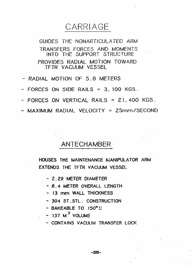
CARRIAGE
GUIDES THE NONARTICULATED ARMTRANSFERS FORCES AND MOMENTSINTO THE SUPPORT STRUCTURE
PROVIDES RADIAL MOTION TOWARDTFTR VACUUM VESSEL
RADIAL MOTION OF 5.8 METERS
FORCES ON SIDE RAILS = 3. 100 KGS.
FORCES ON VERTICAL RAILS = 21. 400 KGS.
MAXIMUM RADIAL VELOCITY = 25mm/SEC0ND
ANTECHAMBER
HOUSES THE MAINTENANCE MANIPULATOR ARMEXTENDS THE TFTR VACUUM VESSEL
- Z.Z9 METER DIAMETER
- 8 .4 METER OVERALL LENGTH
- 13 mm WALL THICKNESS
- 304 ST.STL. CONSTRUCTION
- BAKEABLE TO 15O°C
- 137 M 3 VOLUME
- CONTAINS VACUUM TRANSFER LOCK
-200-
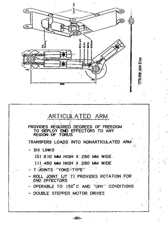
ARTICULATED ARM
PROVIDES REQUIRE^ DEGREES OF FREEDOMTO DEPL0Y END EFFECTORS TO ANYREGION O> TORUS
TRANSFERS LOADS INTO NONARTICULATED ARM
- SIX LINKS
(5) 610 MM HIGH X 280 MM WIDE
( D 4 8 Q MM HIGH X 280 MM WIDE
- 7 40INTS "YOKE^TYPE"
- ROLL JOINT (JT 7) PROVIDES ROTATION FOREND EFFECTORS
- OPERABLE TO 150*C AND "UHV" CONDITIONS
- DOUBLE STEPPER MOTOR DRIVES
-201-
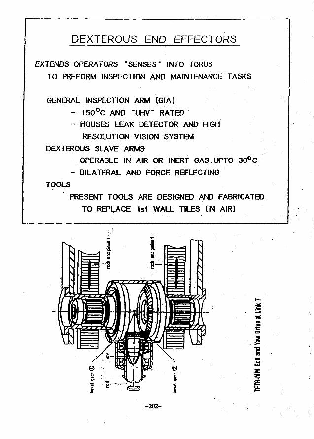
DEXTEROUS END EFFECTORS
EXTENDS OPERATORS "SENSES" INTO TORUSTO PREFORM INSPECTION AND MAINTENANCE TASKS
GENERAL INSPECTION ARM (GIA)- 150°C AND "UHV" RATED- HOUSES LEAK DETECTOR AND HIGH
RESOLUTION VISION SYSTEM
DEXTEROUS SLAVE ARMS
- OPERABLE IN AIR OR INERT GAS UPTO 30°C
- BILATERAL AND FORCE REFLECTING
TOOLS
PRESENT TOOLS ARE DESIGNED AND FABRICATED
TO REPLACE 1st WALL TILES (IN AIR)
-202-
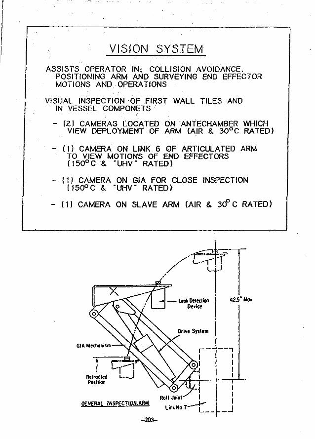
VISION SYSTEM
ASSISTS OPERATOR IN: COLLISION AVOIDANCE.POSITIONING ARM AND SURVEYING END EFFECTORMOTIONS AND OPERATIONS
VISUAL INSPECTION OF FIRST WALL TILES ANDIN VESSEL COMPONETS
- (2) CAMERAS LOCATED ON ANTECHAMBER WHICHVIEW DEPLOYMENT OF ARM (AIR & 30°C RATED}
- (1) CAMERA ON LINK 6 OF ARTICULATED ARMTO VIEW MOTIONS OF END EFFECTORS(15O°C & "UHV" RATED)
- (1) CAMERA ON GIA FOR CLOSE INSPECTIONM50°C & "UHV" RATED)
- (1) CAMERA ON SLAVE ARM (AIR & 30° C RATED)
GIA Mechanism
RetractedPosition
GENERAL INSPECTION-ARM
- 2 0 3 -
Link No 7- j _ I j
CONTROL SYSTEM
AUTOMATICALLY (OR MANUALLY) DEPLOYS ARM
TO SELECTED LOCATIONS
USES "PROMS" TO SIGNAL PULSE GENERATOR
OF SEQUENCE OF STEPS
POINT TO POINT CONTROL SYSTEM
COMPARATOR VERIFIES PROPER MOTOR ROTATION
VS. ENCODER SIGNAL BEFORE PROCEEDING TO NEXT STEP
ENCODERS FEEDBACK ARM ORIENTATION TO
GRAPHICS SIMULATOR
IK/iijV'/
TFTfl-MM Vision and Lighting System
-204-
cumir aiONAL. imV),
•COUNT80ARO ! i i i i r r . / .
ABS.POS. ICOUNTER <
TFTR-MM Control of Links
U.S. - JAPAN WORKSHOP P 118
Nagoya, JapanAugust 1 — 4, 1988
CIT IN-VESSEL REMOTE MAINTENANCE
by R. Hager
(presented by R. Gallix)
-206-
GENERAL ATOMICS
CIT In-Vessel Remote Maintenance Description
Abstract
During D-T operation of the tokamak, activation of the plasma chamber com-ponents by plasma neutrons will preclude all personnel access, and all maintenancewill be accomplished remotely. Major maintenance tasks include:
• first wall tile inspection, replacement, and height adjustment;
• leak detection and-repair;
• divertor inspection and replacement;
• divertor or first wall modifications;
• port bellows replacement;
• rf launcher inspection;
• in-vessel diagnostic inspection and repair.
Maintenance within the plasma chamber is via two dedicated midplane portsusing a remote maintenance system based on two articulated booms. The mainte-nance booms will each be housed in an evacuated enclosure to allow in-vessel work,such as remote leak detection, without venting the machine vacuum vessel Neu-tron shielding wffl be provided to prevent activatmhands-on maintenance of these devices.
Two vertical ports, each located approximately 90 degrees from the boommidplane ports, will accommodate inspection and viewing capabilities. Manipula-tive devices, capable of entering the plasma chamber in a "tiff"mTtn amount of timeafter a pulse, will be housed in shielded vacuum enclosures permanently mountedon the vertical ports.
-207-
esamtmMi ATOMICS
IN-VESSEL REMOTE MAINTENANCE
OVERALL REQUIREMENTS FOR REMOTE MAINTENANCE SYSTEM
• MAXIMIZE USE OF EXISTING TECHNOLOGY AND HARDWARE
• COMPATIBLE WITH N % CIT AVAILABILITY
• FAIL-SAFE RECOVERY
• VACUUM COMPATIBILITY
• NEUTRON SHIELDING TO PREVENT ACTIVATION
• COLLISION AVOIDANCE PROTECTION
• GAMMA RADIATION HARDENING (ELECTRONICS)
IN-VESSEL REMOTE MAINTENANCEMAJOR MAINTENANCE TASKS
REMOTELY MAINTAIN THE VACUUM VESSEL AND INTERNALS INCLUDING:
• FIRST WALL THE INSPECTION. REPLACEMENT. AND HEIGHT ADJUSTMENT
• LEAK DETECTION AND REPAIR
• DIVERTOR INSPECTION ANO REPLACEMENT
• DIVERTOR OR FIRST WALL MODIFICATIONS
• PORT BELLOWS REPLACEMENT
• RF LAUNCHER INSPECTION
• IN-VESSEL DIAGNOSTIC INSPECTION AND REPAIR
• VACUUM VESSEL CLEAN-UP
-208-
"J» CCHEft/U. ATOMICS
IN-VESSEL REMOTE MAINTENANCEPLAN VIEW
- VERTICAL rxmt
ARTICULATED BOOMMANIPULATOR UBUI
INVESSEL REMOTE MAINTENANCE SYSTEMUCWKOM VltW
-INSVECTIOH/nEWINe MANIPULATOR
-SMICLOARTICUCATCO BOOMUAWPULATM <*tMI
IHICLO n.u«•OKOH 2IRCONIUMIIVMIOC
IRANSPOftr CASK
AOMTWMAL MMSrSTCMSAKO COW«P«CHTnor
T«AMS»O<IT tWUCHTi
• •MSVS1CUTOMS
MHOTC TCSTHMMMTOTlrNSW M I f SWCSTSUMMS>IIU«E«tATlO«l AMOCOHTNOt
-209^
• cf*mm*L ATOMICS
IN-VESSEL REMOTE MAINTENANCEMANIPULATOR SYSTEMS
ARTICULATED BOOM MANIPULATOR. 2 REQUIRED
PERFORMANCE REQUIREMENTS:
• STORED AND OPERATES IN HIGH VACUUM (10'* torr)
(GLOW DISCHARGE CLEANING AND BAKEOUT)
• COLLISION AVOIDANCE
• FAIL-SAFE RECOVERY
• GAMMA RADIATION HARDENING (~10* rads/hr)
• NEUTRON SHIELDING TO PREVENT ACTIVATION
• FIT THROUGH 14.5 in. WIDE x 40 in. HIGH PORT
• OPERATE IN SMALL TOROIDAL VESSEL CROSS SECTION
timNHKALMTOMICS
IN-VESSEL REMOTE MAINTENANCEINSPECTION/VIEWING DEVICE*
(WMIKI
Utilizing "LINKS" mechanism developed by Taylor Hitec Limited.
-210-
• CBNMHM. ATOMICS
IN-VESSEL REMOTE MAINTENANCEMANIPULATOR SYSTEMS
ARTICULATED BOOM MANIPULATOR (ABM)
DESIGN DESCRIPTION:
• DRY LUBRICATED BEARINGS AND ENCAPSULATED DRIVE MOTORS
• TV CAMERAS WITH AUTO TRACKING AUGMENTED WITH GRAPHICS
SIMULATOR
• SERIES-REDUNDANT ARTICULATED LINK BEARINGS AND MANUAL WITH-
DRAWAL MECHANISM
• RADIATION-HARDENED T V CAMERAS WJTH QUICK DISCONNECTS
• HIGH-EFFICIENCY NEUTRON SHIELD PLUG (BORON ZIRCONIUM HYDRIDE)
• NESTED FOLDING ARTICULATED LINKS
• COMPACT SERVO-MANIPULATOR WITH INTERCHANGEABLE END EFFECTORS
IN-VESSEU REMOTE MAINTENANCEARTICULATED BOOM MAMPULATOR
(REDUCED SIZE TFTR-TYPE BOOM)
CMfTWtMM
M U
KrttCIBn
-211-
> c'cNmaat ATOMIC*
IN-VESSEL REMOTE MAINTENANCESPECIAL PURPOSE TOOLS
-TILE INSTALLATION/REMOVAL MACHINE
•COLLET
TILE
BELLEVILLE SPRINGS
VESSEL
• c m n u t ATOMICS
IN-VESSEL REMOTE MAINTENANCETILE END EFFECTOR WORKING ENVELOPE
SPECIAL PURPOSE TOOLS
-212-
CCMEfML ATOMIC*
IN-VESSEL REMOTE MAINTENANCEELEVATION VIEW
IH3PCCTI0H/VICWINC UUHPULATOK
•CLOO SHICLOMTICUKTCO SOONUUMFULMOfl <MU|
VACUUU ISOLATIOH VM.VC
| W . V E S S E L R E M O T E MAINTENANCEDIVERTOR MODULE INSTALUTION/REMOVAL MACHINE
SPECIAL PURPOSE-TOOLS
COHMKHHO mo
CtlANK
-213-
ATOHHCS
LEAK TELESCOPE
T. Jensen M. Fisher
IN-VESSEL REMOTE MAINTENANCETRANSPORT SYSTEMS
SEALING SURFACE (SEALS TOABM ANTECHAMBER PORT)
SUtHMe SHIELD LIOMANUALLY ACTUAT"a PINION SYSTEMMANUALLY ACTUATED RACK
-SLIDING LIDENCLOSURE
fILE TRANSPORTCASK CAVITY
CAST LEAD
WHEEL CASTERS
REMOVABLE SLEEVE INSERT
-214-
CHOPPER. ROTARrFEEDTHBOUCH. DC MOTORANO ROTARY PICKUP
VARIABLEIEAKVALVE:
LEAK TELESCOPE(NUDE mMATKM6MJ6E. COU
LEAK TELESCOPE TEST SET-UP
LEAK TELESCOPE
• . PROTOTYPE SUCCESSFULLY TESTED AS PART OF THE CIT RAD PROGRAM.FURTHER TESTING WAS ALSO CONDUCTED UNDER TFTR SPONSORSHIP.
• PRINCIPLE USES A COLUMATED K M GAUGE TO DETECT THE DIRECTIONALFLOW (*.«., LEAK) OF MOLECULES W A VACUUM.
• BY "CHOPPING" THE FLOW OF MOLECULES, LEAKS OF W to1<T» TORR-L/SEC WERE DETECTED AT ONE METER DISTANCE.
• TESTING ADDRESSED ISSUES SUCH AS: TIME RESPONSES (SCANNING SPEED),LEAK TO DETECTOR DISTANCE, SIGNAL PHASE AND MAGNITUDE.
• FOR CIT, THE DEVICE WOULD DEPLOY ON A REMOTE MANIPULATOR BOOMAND AUTOMATICALLY SCAN THE WALLS OF THE VACUUM VESSEL FORLEAKS.
-215-
LEAK DETECTOR RESPONSE
TELESCOPEDETECTOR
-216-
JULY 1988 UPDATE2im err
VACUUM COMPATIBILITY
• LEAK DETECTION IN VACUUM
• REMOTE VIEWING IN VACUUM
• MOST OTHER OPERATIONS IN INERT GAS AT ONE ATMOSPHERE
• ALL MATERIALS CHOSEN FOR VACUUM SUITABILITY
-217-
Japan-US Workshop
on
Vacuum Technologies for
Fusion Devices
IPP, Nagoya University
August 1-4. 1988
Experience with In-vacuua Remote Manipulators
for Fusion Research
Y. Murakaai and K. Obara
Japan Atomic Energy Research Institute (JAERI)
Maka Fusion Research Establishment
Naka-aachi, Naka-gun, Ibaraki-ken, Japan
-218-
Experience with In-vacuu« Remote Manipulators for Fusion
Research
(Abstract)
A number of works have been done at JAERI to develop elemental
techniques for in-vacuum manipulators through the process of
fabrication and performance test of an in-situ coating- machine,
a leak hunting device and a multi-joint remote handling
machine. Major technical problems encountered in the course of
the development are the selection of driving methods,
improvement of lubricating materials and mitigation of
outgassing from constructional materials. The purpose of the
in-situ coating machine is to inspect and repair the eroded or
damaged surface of TiC-coated tiles in the JT-60 vacuum vessel.
The machine basically consists of an in-vacuum manipulator with
a long arm of four degrees of freedom, a quartz fiber scop* and
ohmically heated titanium evaporators. The leak bunting device
is composed of a light-weighted manipulator and a small
ionization gauge attached- to the tip of the manipulator arm.
Leak points can be located by moving the ionization gauge along
the inner wall of the test vessel. In the above two
applications, MoS2-coated Inconel (or stainless steel) is used
for most movable parts including gears, Ag-ionplated stainless
steel for ball bearings, and a self-lubricating alloy for slide
bearings. A preliminary test was also made of an in-vacuum
remote handling machine with multiple joints. In this case,
each joint has its own driving unit consisting of electric
motor, torque sensor, electronic circuit for control, gears,
bearings, etc., and is exposed to a high vacuum. A special
hydrocarbon grease is used as the lubricant since no solid
lubricating materials endure the strong forces fallen on the
gears of the joint.
-219-
NECESSITY OF IN-VACUUMREMOTE MANIPURATORS
Rapid in-vacuum inspection andmaintenance capabilities wiHincrease fusion machine availabil-ities and safety.
Remote maintenance tasks to becarried out in the vacuum vesselinclude:1) Visual inspection of components2) Leak detection and repair3) Wai surface analysis4) Replacement of in-vessel
components
SOME EXPERIENCES OFIN-VACUUM MANIPULATORS FOR
FUSION RESEARCH AT JAERI
Limited works have been done tostudy elemental techniques neces-sary to in-vacuum manipulators,though neutron damage problemshave not been included.
Main devices tested are:a) In-situ coating machine for
JT-60b) Leak hunting devicec) Multi-joint remote handling
machine
Jill.
u
IN-SITU COATING MACHINE
Objectives:1) Inspection of TiC-coated tiles
under high vacuum2) Repair of eroded or damaged
surface by TiC depositionwhen necessary
The machine basically is an in-vacuum manipulator with titaniumevaporators (or a fiberscope) atthe arm, and is designed to mounton a vertical port of the JT-60vacuum vessel.
MECHANISM OF GOINGUP AND DOWN ALONGZ AXIS
-K.
DRIVINGPOWER UNIT
MAGNETIC FLUID•« ROTARY
MOTION SEAL
VACUUMVESSEL
Driving mechanUms of th« mtnipulator for the in-situ coating machine.
LEAK HUNTING DEVICE
Leak hunting is one of the impor-tant functions of in-vacuummanipulators for fusion machinesbecause the vacuum vessel isinaccessible from the outside dueto big and complex structure and.in the next generation machines,also due to activation problems.
The leak hunting device consistsof an in-vacuum manipulator andan ionization gauge attached tothe tip of the manipulator arm.
m
ARTIFICIAL LEAK(LEAK RATE •2 .4xl6 7 Pom 3 /s )
.30nm
IONIZATION-GAUGE T
VACUUM VESSELWALL
SCAN SPEED(VARIABLE)
SQ:
CO
H!
SCAN SPEED3mm/s
BACKGROUND PRESSURE4 x l 6 5 Pa
12mm/s
TIME30min
MAJOR TECHNICAL PROBLEMSFOR THE DEVELOPMENT OFIN-VACUUM MANIPULATORS
Major Technical Problems:1) Selection of driving methods2) Selection of lubrication
methods and materials3) Mitigation of outgas from
constructional materials atservice conditions
The methods and materials shouldbe selected by considering thefollowing items:a) Vacuum conditionsb) Temperature rangec) Required torqued) Applied stress
Typical rtcordef »icn«U obtained by utinf a leak hunlinf dtviet.
SUMMARY OF SERVICE CONDlTiO^ DRIVING METHODS.
LUBRICANTS. AND
NTr STRUCTURAL MATERIALS
FOR THREE WFFERENT APPLICATIONS AT JABRI
NAME OF
DEVICE
SERVICECONDITION
DRNMGPOWERUNIT
LUBRI-CANTS
STRUCTUREMATERIALS
OTHERMATERIALS
I n - s W coatingmachine
<iO-»Pa<300C
AC motor.Outside vacuumVMMi.Magnstic'fluidrotary motion
MoSt coating*{most movablepart»».SL aloy (sidebtar'mas)
Inconel andStainless steal
TiC coatings(bolt detach-ing)
Leak huntingdevice
<1O-«Pa<180C
DC motor with
Inside vacuum
vassal
MoS. coatings(most movableparts).Ag coatings(be* bearings)
Al aloy
PTFE (cableinsulation)
Multi-jointremote henoYngmachine
<10-«PaRoom tempi
DC motor withaarvnnwchanism.Inside vacu.-^vessel
Special hydro-carbon grease(most movableparts).SL aloy (sidebearings)
Stainless steal
PTFE (cableinsulation)
CONCLUSION
There are no allround techniquesfor the driving and lubricationof in-vacuum manipulators.
In designing a manipulator, themost appropriate technique shouldbe selected by considering boththe vacuum and temperature conditions during operation and themechanical conditions such asrequired torque and appliedstress.
It is very important to establishknow-hows or data base in thistechnical field.
-225-
-226-
Design and Testing ofa Manipulator Arm Used in
High Vacuum
Kenjiro OBARA*, Kazuyuki NAKAMURA*,Yoshio MURAKAMI*, Masao OBAMA**,Mitsunori KONDOH***
•Naka Fusion Research Establishment, JAERI,Naka-machi, Naka-gun, Ibaraki 311-02, Japan
** Research and Development Center,Toshiba Corporation, 4-1, Ukishima-cho, Kawasaki-ku,Kawasaki 210, Japan
*** Fusion Technology Development Office,Toshiba Corporation. 1-1-6, Uchisaiwai-cho,Chiyoda-ka, Tokyo 100, Japan
US-Japan Workshopon Vacuum Technologies for Fusion Devices
held at Institute of Plasma Physics,Nagoya University
1-5 August, 1988
-227-
Design, and Testing of a Manipulator Ara
Used in High Vacuum
Kenjiro Obara*, Kazuyuki Nakamura*, Yoshio Murakami*,
Masao Obama**. Mitsunori Kondoh***
* Naka Fusion Research Establishment, JAERI, Naka-machi, Naka-
gun, Ibaraki 311-01, Japan
** Research and Oevelopaent Center, Toshiba Corporation, 4-1
Ukishima-cho, Kawasaki—ku, Kawasaki 210, Japan/ •
*** Fusion Technology Development'Office, Toshiba Corporation,
1-1-6, Uchisaiwai-cho. Chiyoda-ku, Tokyo 100, Japan
Abstract
A aultijoint remote manipulator was considered to use for the
inspection of in—vessel components of fusion devices.
In designing; the in—vacuum manipulator, major technical issues
are the selection of lubr.ication methods and materials, for mov-
able parts and introduction of ara joint release mechanisms which
work on the occasion of accidental failures.
A performance test was made on a single joint with two axes.
A special hydrocarbon grease was used as the lubricant since
solid lubricant vataxials do not endure, the strong forces loaded
on the gears of the joint. Hire of shzpe memory alloys(SMA) were
utilized to the actuator of the arm joint release mechanism.
It has been demonstrated that' the machine works well in vacuua
for more than 1,400 hours. ,
-228-
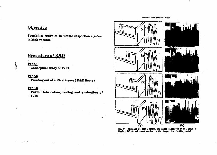
COMPUTE! AIDED INSPECTION ROiOT
Objective
Feasibility study of In-Vessel Inspection Systemin high vacuum
Birocedure of R&D
P r o dConceptual study of IVIS
Proc.2Pointing out of critical issues (RAD items)
Proc.3Partial fabrication, testing and evaluation ofIVIS
•f rtfcat Mttm (•) no4tl diipUytd en ch* trtphic»et»»l robot aetlo* In tht imp«ctlon ftcllltjr KMltl
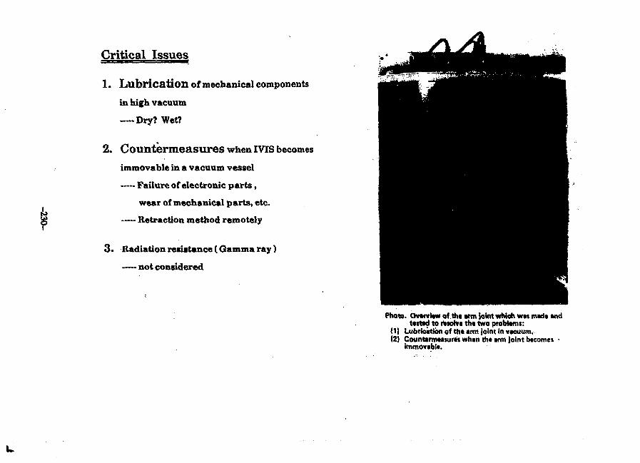
Critical Issues
1. Lubrication of mechanical components
in high vacuum
— Dry? Wet?
2. Countermeasures when IVIS becomes
immovable in a vacuum vessel
— Failure of electronic parts,
wear of mechanical parts, etc.
— Retraction method remotely
3 . Radiation resistance (Gamma ray)
— not considered
Photo. Ovtrvtaw of tht arm Joint wMoh wtt madt andtested to rtwWt tht two probtam:
(1) Lubrication of tht arm Joint In vacuum.(2) Counttrmtaturts whtn tht arm joint btcomes •
immovablt.
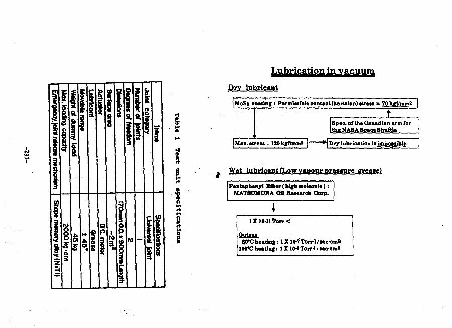
j
I p g
t
sft
0
oH>MlH«O
fti
Lubrication in vacuum
Dry lubricant
MoSj coating : Permittible contact (hertiian) stress * 70 ktf/mm2
±Spec, of the Canadian arm forthe NASA Space Shuttle
Max. stress : lS0kff/mm2 Dry lubrication it iwpotiible.
Wet lubricant (Low vapour pressure grease)
Pentaphenyl Ether (hifhwolecule):MATSUMUF4 OU lUaeareh Corp.
1X10-H Torr <
OutgatWCheating: IX10-'TorrWtec-cm*
100*C heatinf:
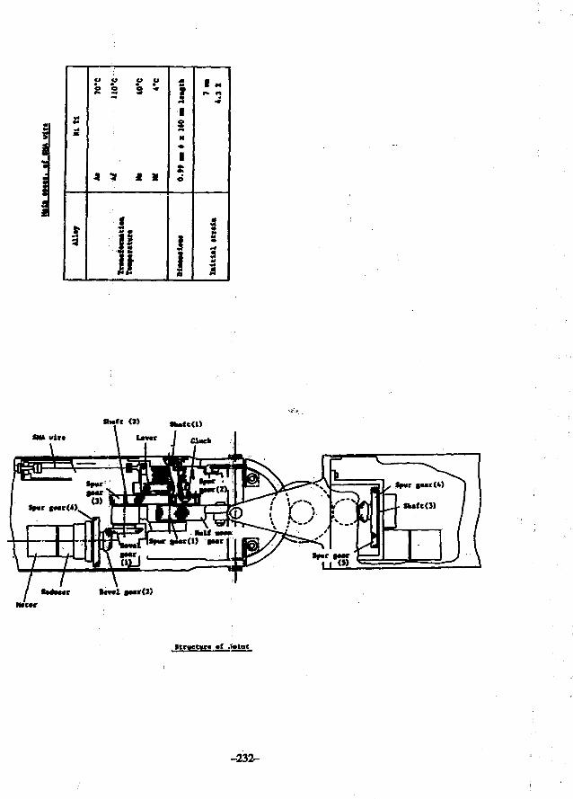
*
1
O O Cl Cl• • • •
S3 S *
•» 3 2 1
; ,
is1!
I3H
1se
DtM
MtM
I
| M
s
i
SM* vlr*
Wctr
Itryeff «f .
-232-
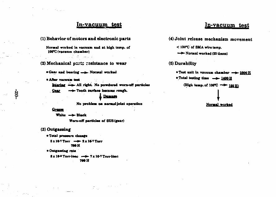
In-vacuum test In-vacuum test
(1) Behavior of motors and electronic parts
Normal worked in vacuum and at high temp, of100*C (vacuum chamber)
(2) Mechanical ports rasistancc to wear
•Gear aad bearing • » Normal worked
• After vacuum teat rBearing —J - All right. No powdered worn-olf particlesGear —^ Tooth surface became rough.
No problem oa normal joint operationQreaae
White —*- BlackWont-off particles of SUS(gear)
(3) Outfassinf• Total preeeure ehaage
5xl«-7Torr —»» i x 1«-TTorr7MH
• Outgasaing rate—•-7 x 10-' Ton-Utec
7MH
(4) Joint release mechanism movement
< 13O*C of SMA wire temp.
—+- Normal worked (S3 times)
(5) Durability
• Test unit in vacuum chamber• Total testing time —*- 1400 H
(High temp, of 100*C —
2900 H
INormal worked
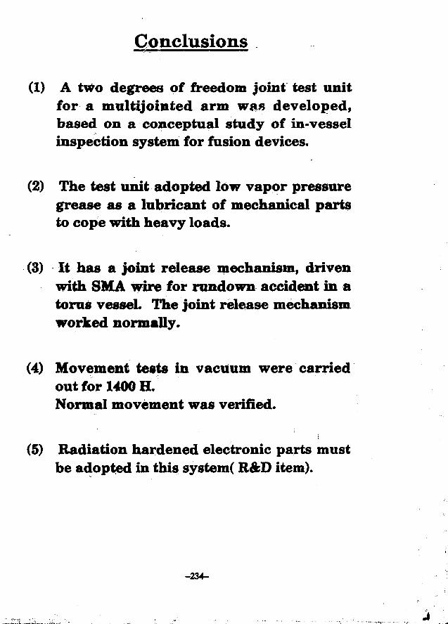
Conclusions
(1) A two degrees of freedom joint test unitfor a multijointed arm was developed,based on a conceptual study of in-vesselinspection system for fusion devices.
(2) The test unit adopted low vapor pressuregrease as a lubricant of mechanical partsto cope with heavy loads.
(3) It has a joint release mechanism, drivenwith SMA wire for rundown accident in atorus vessel. The joint release mechanismworked normally.
(4) Movement tests in vacuum were carriedout for 1400 H.Normal movement was verified.
(5) Radiation hardened electronic parts mustbe adopted in this system( R&D item).
-234-
Pump Limiter Analysis in Vacuum Physics Viewpoints
T. Kawamura and K. AkaishiInstitute of Plasma Physics, Nagoya University, Nagoya 464-01, Japan
AbstractThe method of estimation for particle removal efficiency of a pump limiter in
conventional vacuum physics viewpoints is developed-and numerical examplesare presented in reference to the ALT-H in the TEXTOE tokamak. Theestimations are consistent with the preliminary experimental results.
§1. IntroductionRecently the effect of a pump limiter is studied for removal of plasma outfiux
in a toroidal system. In a pump limiter the scrape-ofif plasma i» guided aloof the
a deflector plate placed at the bottom of the guiding duct on the limiter side. A-part of neutralized particles ejected from the deflector plate are introduced intothe pumping ductas a molecular flow. For estimation of neutral particle exhaustwith a pump limiter a Monte Carlo method is usually employed, however, it isinferred that the exhaust efficiency of gaseous particles as a molecular flow mightbe estimated with making use of conventional vacuum-physical methods to someextent
In this study the method for estimation of the particle removal efficiency of apump limiter in view of conventional vacuum physics is developed. In this casethe fraction of neutrals which arc ejected from the deflector plate and directly goto the pumping duct opening becomes important. The numerical calculations aredone in reference to the ALT- II in the TEXTOR tokamak and compared with thepreliminary experimental results.
f 2. Theoretical AnalysisHere a theoretical analysis based on conventional vacuum-physical method
for the modelled configuration illustrated in Fig.l is given in general viewpoints.The definitions of parameters are as follows
-235-
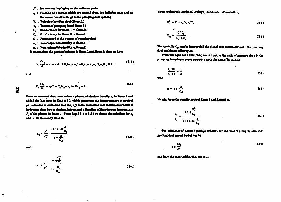
n
vtv,c,c,s"I
"»
loa carraat impiafiac a« tha daAactar platefraction afaawtraia wkiek m ajaatat ftam tha daOadatr pat* •*« •*tha t—w tii—dteacMy a» »»>•» f M | !•» <•» opwlif
r«np • • • • ! •! H I I—Mmml
ifpiipi»(d»i I1
• sd
* *
tkftttiMnUM *i lm
( M )
apka»aafilii>iiadaaaMy»1faiIaaailaadaTM«tnlafM«tral
DM ••
•nd
(14)
whtn wt introducad tha Ibllowini qutntiUu for »bbrovinlioi>,
(2-5)
(2-6)
Tha quantity C^eaa ba iatarpratatt tha global eonductaaea batwtan tha pumpincduet and tha a«Mki««iaii.
From tha Ioa.( M ) aad (1-4) wa ean dariva tha ratio of prmura drop in thtpuapiac d«etd«*topiMtpapwationat tha bottom of Room 2 u
with•",(•) (2-?)
K m 1 + • (2-8)
Wa alao hava tia daaaitr ratio of Room 1 and Room S aa
ft(2-9)
Tha affidaoqr of MMtral »artiel« axhautt par on* unit of pump tytum witht«ldimfd«>etiha«ldbadaflMa'by
>*. (MO)
and from tha raavllof Ea..<K) wa hava
(till)
ar if w* MM the ratio efrnann •*•• * daHaa* ay Bq. (M) we aba have U|i athar
(J-ll)
FarthaaiaJili tinafnogaiaiac*>tv»c»»tafcaCt—«olD.tfeair.hav*
C^ialq.O-
(1-13)
which nM<MiMil«n»lt»alj-
Tha > w ia l a . (1-1) fcr>ninHia >f •—trala i* Emm I k ataaly mated togsvatkaateaaBaacaaeiafMaiak!*, hawvaf, ia tha rial aHnaUta •aartafiaMprafaeaa wkk lialantn afaawtral* aaa* haak to ta*with J*. If w« tak*thi*«*Ktiatoac«nBt laa.
U -n
whan K i« the araaartiaa efhM&Stftriaf iaaa ia ieaieea aaitialaa ia Ratal 1.Wa caa have «, aad «, tnm lae . (t-l)«ad (»-» aa
and
(3-4)
where we agaia iatraaaead tha following quantities for abbreviatioo,
(8-5)
(3-6)
(S-?)
ID thit caa* tha axhauat affidancy of oaa unit of pump tyttwn it given by
(3-8)
If K « 0 wa hava C,* • C,+, Ct* > C, and Cwr' * Cir, th.a K, (Ml) U
Hara wa riial valuta af aaraaator* <ar « M unit of punpinfflyatoia by rafaraaot to tte ALT4I ia TBXTOt, whar* tkt plaana flow comingA w S guMtag oaata aa hath aMat af tha HniUl limitor art ntutraliMd on th.defector aiatot aad ga iala UM «MMn«a aumvlii
Tha «»a«cta«c« caacaraed tta ha ayah*lad by »afcia«waeof the ideal pump
Thalia
j l A Ik.(4-1)
telecalar weight afgaa par H,gaa at MO "Kwe have
C » 4 4 A 6b. (4-S)
If we take;
Af; Area af the ipaalagef j—plag <e»t
A, « » X l » x a - Wea^A , * 17X17 - MOaa1
v,«(sxuxanxt - aooo«a*»
thea fioa. B, (4-J) wa have
C,s44XM ~ S4X1O* titC,* 44X900
aad Jfc« pump apaad of a turbo •alacntar pwnp inatalbd at th« bottom of thapumpwf duct u givaa in tha liUratura aa «
S - 4 . 0 X 1 0 3 « s .
Wa attimaU tha ionisatioa aflaetia thagutdiB|'««taa
wbara wa aatumad, for asampia, n« » 10"a>4a>d T, z 20 tV ( <oiua>1.4XlO*cm>rM- If wa tentatively taka tha phanawanotofical ooaflidanto at
i) « 0.5 and K » 0.7.
W«obtaiafroa«m.(J-«X»-«)aod(3-7),
C , ' " UXIO'.C,* 8.2X101
• Tka« fram t^. (M) wa have for tfca axhautt efficiency of one unit of pump limi uraa
e » 0 . J 7 .
Tfca above valna of a ia tha azaauat affidaney with raapact to the plaamapartida awna* flawiag tea* KM g«M<af eW.t opaaiaic The global e/Hciencyaha«MbeibHUila*thaaba»a»ahia^«k»>Uad by tha pfoportion of the plaamacurraat gateg Uat the l a U b f aVtat apaatac M H | the total eurreat flowinc outfraam the M I I ptaaaM to <ka tOL. TUa pnpaHiM ia aparoximaUly |ivan, in taileaaa, by tba ratla baawaaei «aa width at tha f«MUg duet opeaiaf and thedrawfcwavn af tha HIM malou af tarua. j , MwItipUad by the factor dua to thedapah praeUaaf aWpkawi §twalfftha — f a t i a fleM liaaein tha SOL, CThavaluaaaffiaiBXTOelt
(4-3)
and if we aaauaa the axponaotial decay with aeale lenfth X, of plaama deneity intheSOtweeaaaatiaato(a«
r«* *.vt\ t "lit
• - «-'.".- (4-4)
Where z, and are tha daptba of the top and bottom of the guiding duct openingrespectively. IfwetakeX.«*om,X|«2emand*,=4cm>ih»ve
<>0.23.
Finally tha global exhaust efficiency of one unit of the pumping tys tern becomes
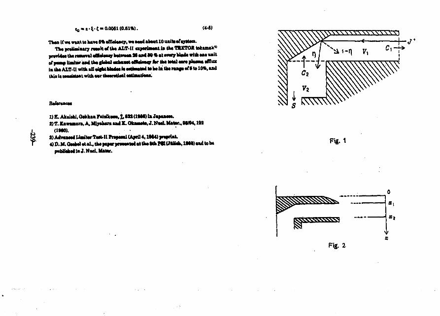
. « f t - J > 0.0061(0.61*). (4-6)
Than If wt want to hava 6% affieiaMy, wa naad about 10 uaiti afayatam.Tha fMltMiaary n w l t rf tha ALT-11ufttmmt la tfc« TtXTOIt tokanak«>
pMvi4Ntk« nawval aOMai^ bMMaft M a ^ M « at weary U a * with « M unitof pwaa UaUtar aa4 tha giabal wdwiatafflatMMgr fcr ta« Mai «ara slaaM affluxin tka ALT- II with all aia*t blate ia aatfawaW la ba la>Oa raaf* af f to 10*. andtfcU ia caaaiataat with a w tinawMatl aaMiatfaaa
Rafaraaeai
Fig. 1
puUiabai in J. N«d. Matar.
0
a,
Fig. 2
Japan-US Workshopon
Vacuua Technologies forFusion Devices
IPP, Nagoya UniversityAugust 1-4. 1988
Calculation of Duct Conductance for Energetic Gasesby Monte-Carlo Method
K. Nakaaura and Y. Murakami
Japan Atoaic Energy Research Institute (JAERI)Maka Fusion Research Establishment
Naka-aachi, Naka-gun, Ibaraki-ken, Japan
-240-

Calculation of Duct Conductance for Energetic Gases by Monte-CarloMethod
(Abstract)
The scattering of energetic (eV order) light atoms and moleculesfrom wall surfaces has been a matter of important concern to fusionvacuum systems in recent years. Though there exist few experimentaldata on the matter, it is expected that the energetic atoms andmolecules do not obey the cosine law of reflection. In the Monte-Carlo calculation of gas conductance through vacuum ducts aroundtorus vessel, we assume on the wall surface a specular-diffusereflection of atoms and molecules. In this model, the distributionof angle of particle reflection obeys cos" 8, where n is a variablelarger than unity and 8 is the angle from the axis of specularreflection. We have calculated the gas conductance through typicalcircular and rectangular ducts by using the specular-diffusereflection model. The result shows that the conductances obtainedfrom the new model are about 50% higher than those obtained from thecosine law model. In order to make clear the possibility toincrease the duct conductance for such gases, experimental data onthe scattering of the energetic particles from actual surfaces wouldbe highly required.
-241--
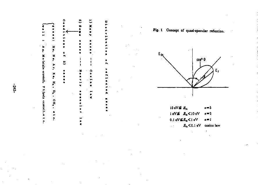
•I
«
•
m
•
Za
•
X
X
* P
Ooa
o
o
to«
-I
•
M
III
• I
III
Oe
Fif. 1 Concept of quwi-ipecular reflection.
ectI*0S
o
m
•
M
0.1eVS£i»<leV n«l
£lB<0.1eV cosine Uw
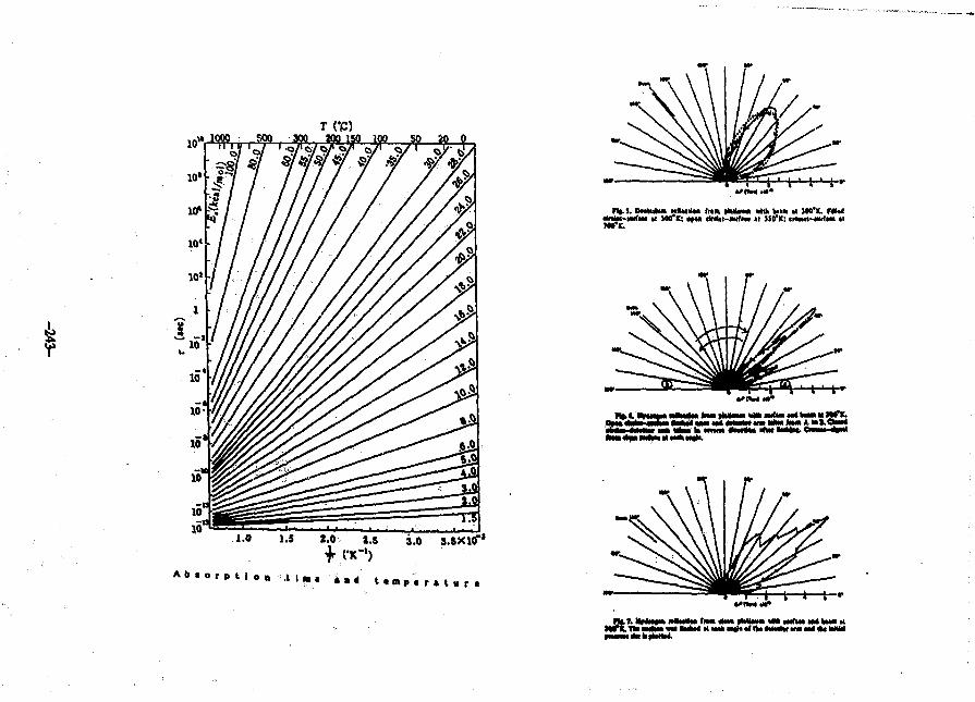
TCP)
1.0 1.5 2.0, 1.5
N(.S. DwtuliM n*MllM (MA HUiim> milk Wm « MO'K. F Mrf u 100i*ICs i fM fMu-wrfm al SIO1*; ctMtn-tulm ••
>ni^miitjnilii*n
Ma «ai M M * anmlw *w> K » i . Oa«a«
t}L7. MHMM w»M»a« t lM aUM fMUMi «M M f w tM Waa MM r E . 1I« aMawi «M laaM at w» aiajla 1 DM ««taahc ana aM «K WaW
kltotM
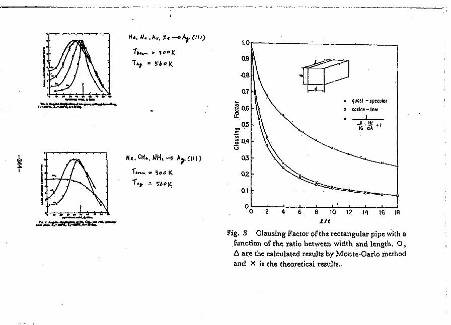
»*. W«.Ar. X*-*ApCUi)
T . ,
* quosi -speculoro cosine-low
Fig. 3 Clausing Factor of the rectangular pipe with afunction of the ratio between width and length. O,A are the calculated results by Monte-Carlo methodand X is the theoretical results.
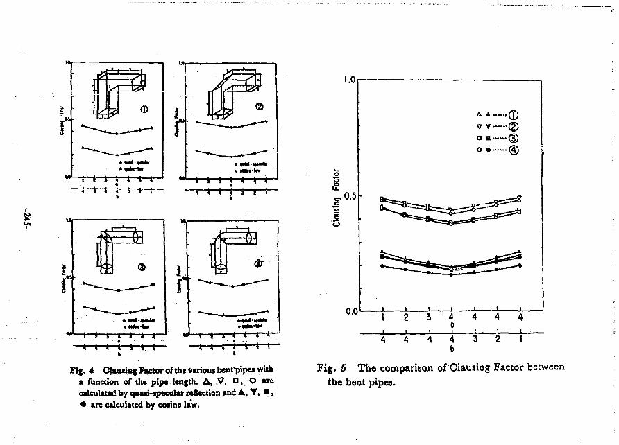
Fig. 4 Clausing Factor of the Various bentpipes witha function of the pipe length. A, .V, D, O arccalculated by quasi-specular reRecttoh and A, T, • ,• are calculated by cosine law.
Fig. 5 The comparison of Clausing Factor* betweenthe bent pipes.
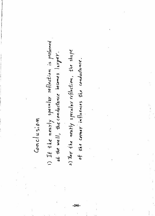
<f)
OT
CO o
O
51
tf "Vs
I
-5 3
V I
T4
VJ
Xl
-246-
U.S. - JAPAN WORKSHOP P 118
Nagoya, JapanAugust 1 — 4, 1988
CIT VACUUM VESSEL,FIRST WALL AND DIVERTOR
CONCEPTUAL DESIGN
(presented by R. GaJUx)
-247-
GENERAL ATOMICS
CIT Vacuum Vessel, First Wall and Divert*Conceptual Design
Abstract
The conceptual design of the vacuum vessel, first wall and divertor systems
for the Compact Ignition Tokamak (CIT} is presented.
The vessel is a continuous, single-wall toroidal shell with vertical and radial
sorts, supported at the outer midplane. The vessel will is cocnplete\y protected by
all-carbon first wall and divertor tiles.
The major requirements and design solutions are reviewed. They concern
dimensional accuracy, vacuum integrity, thermal management (8 GJ fusion yield
over 5 sec, vessel •* 350*C) and structural integrity (11 MA plasma disruptions)
for the vessel; and radiative/conductive cooling, 350*0 outgassing, diverted planma
sweeping and remote maintenance for the first wall and divertor.
-248-
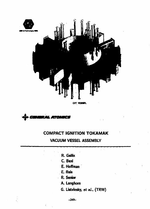
CIT VESSEL
COMPACT IGNITION TOKAMAK
VACUUM VESSEL ASSEMBLY
R. GalHx
C. BixiE. Hoffman
E. Rets
R. Senior
A. Langhom
G. Listvinsky, et ai., (TRW)
-249-
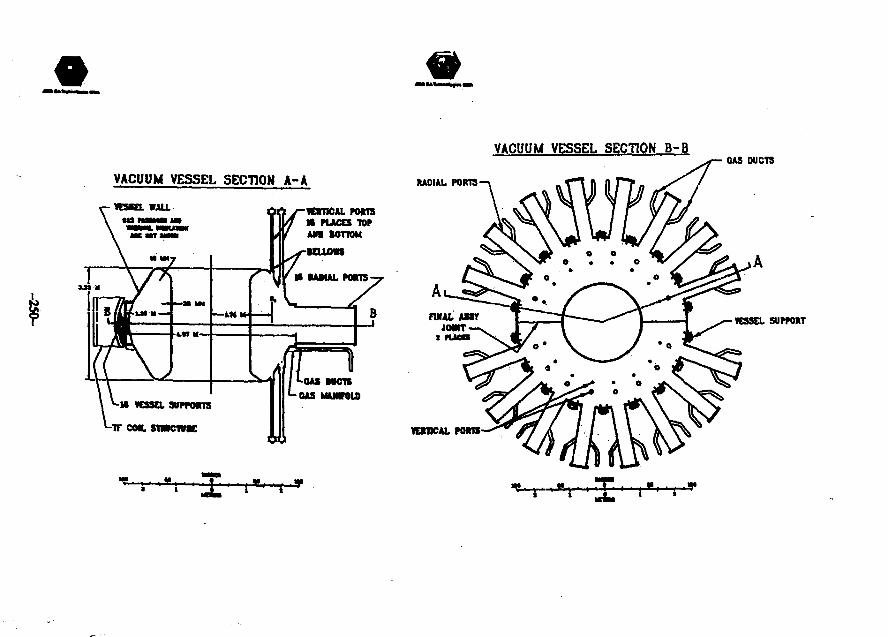
VACUUM VESSEL SECTION B-B
VACUUM VESSEL SECTION A-A
VOmCALMRlSM PUCES TOPAn tonoM
u vessawmnsIF COR. STWCTVK
i » , - i T i ) » i1 JL »
GAS DUCTS
RACIAL PORTS
vcmcAL nan
VESSEL SUPPORT
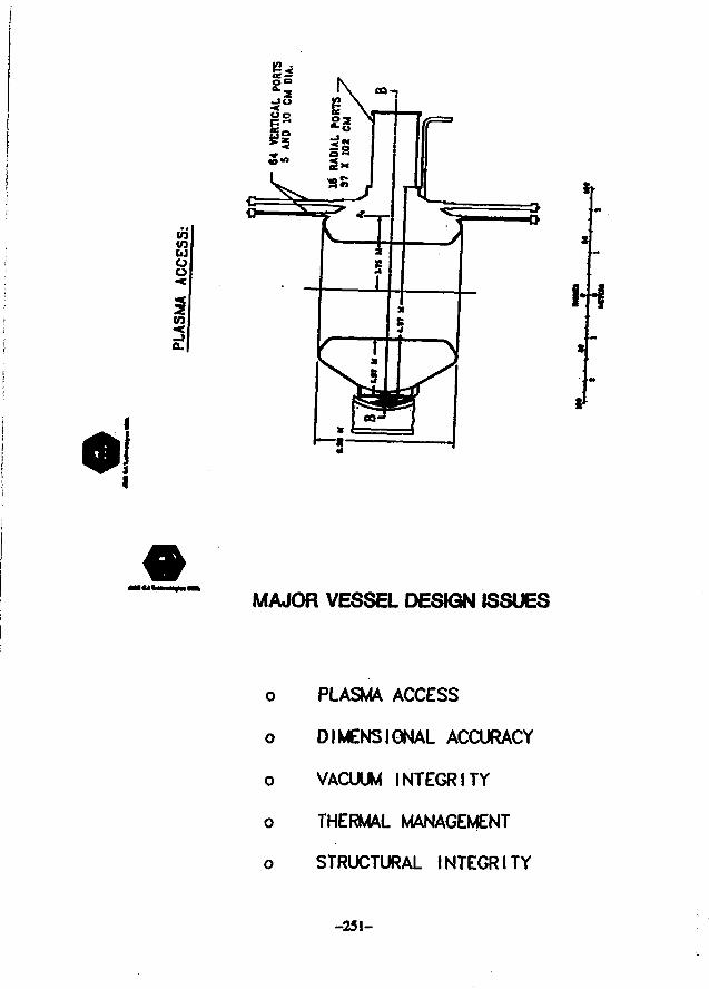
OT
&OO
in
2,I+S
MAJOR VESSEL DESIGN ISSUES
o PLASMA ACCESS
o DIMENSIONAL ACCURACY
o VACUUM INTEGRITY
o THERMAL MANAGEMENT
o STRUCTURAL INTEGRITY
-251-
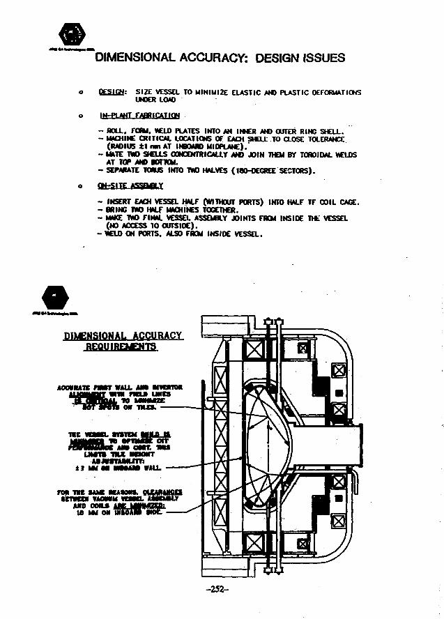
DIMENSIONAL ACCURACY: DESIGN ISSUES
Q££1£N: SIZE VESSEL TO MINIMIZE ELASTIC AND PLASTIC DEFORMATIONSUNDER LOAD
IN-PLANT FABRICATION
- BOLL. FORM, WELD PLATES INTO AN INNER AND OUTER RING SHELL.- MACHINE CRITICAL LOCATIONS OF EACH SHELL TO CLOSE TOLERANCE
(RADIUS ±1 mn AT INBOARD MIDPLANE).- MATE TWO SHEUS CONCENTRICALLY AND JOIN THEM BY TOROIDAL WELDS
AT TOP AND IOTTCM.- SEPARATE TORUS INTO TWO HALVES (180-OEGREE SECTORS).
ON-SITE
- INSEItr EACH VESSa HALF (WITHOUT PORTS) INTO HALF TF COIL CAGE.- BRING TWO HALf MACHINES TOGETHER.- MAKE TWO FINAL VESSEL ASSEMBLY JOINTS FROM INSIDE THE VESSEL
(NO ACCESS TO OUTSIOE).- WELD ON PORTS, ALSO FROM INSIDE VESSEL.
DIMENSIONAL ACCURACYREQUIREMENTS
ACCURATE mn WALL AMI MVCRTMWIN nCtB UNES
ON -mxs.
. TOTEM HJUL-O.
UMTTS -nut mxmrAaJWTAMUTY:
tl mm UNMANS WALL
AND OMLS10 MM ON
-252-
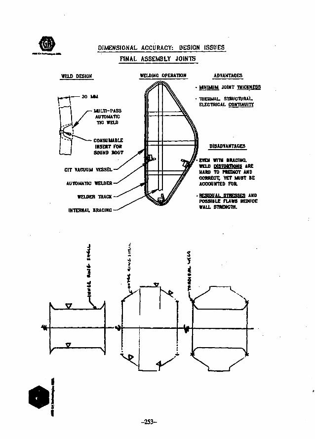
DIMENSIONAL ACCURACY: DESIGN ISSUES
FINAL ASSEMBLY JOINTS
WELD DESIGN WELDING OPERAHON
rr 30 MM
MULTI-PASSAUTOMATICTIG WELD
CONSUMABLEINSERT TOR
SOUND ROOT
CIT VACUUM VESSEL
AUTOMATIC WELDER
WELDER TflACK
INTERNAL BRACINC
ADVAHTAOES
MINIMUM JOINT THICKNESS
THERMAL. STRUCTURALELECTRICAL CONTINUITY
DISADVANTAGES
EVEN WITS BRACING.
WELD msTwrnoNs AREHARD TO PREDICT ANDCORRECT, YET MUST BEACCOUNTED FOR.
RESIDUAL STBEjaSEff ANDPOSSIBLE FLAWS REDUCEWALL STRENGTH.
-253-
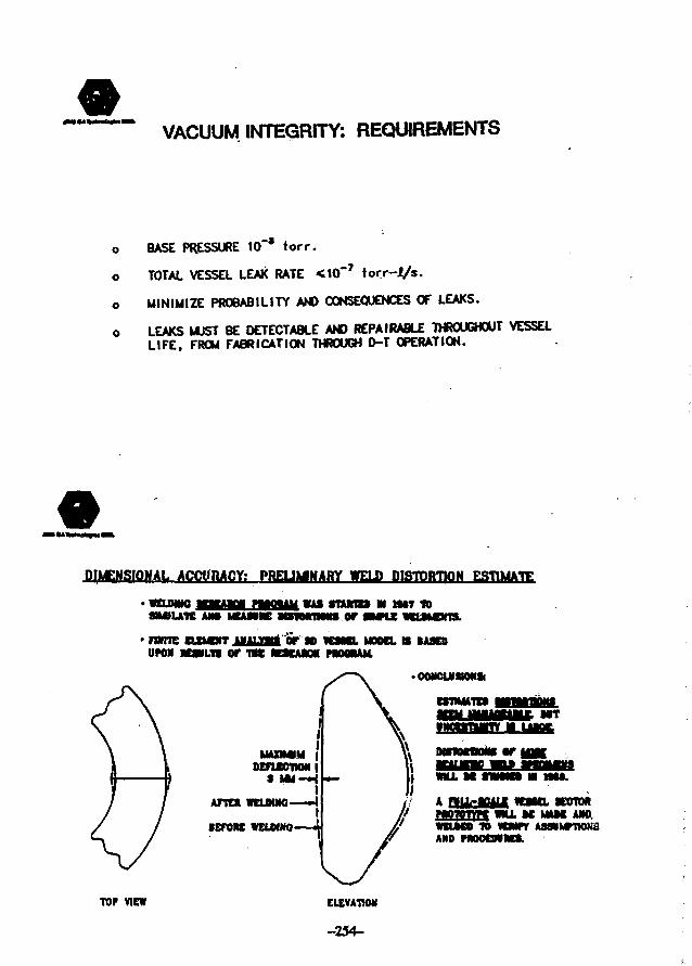
VACUUM INTEGRITY: REQUIREMENTS
o
o
o
o
BASE PRESSURE 10"* lorr.
TOTAL VESSEL LEAK RATE <10~7 torr-l/s.
MINIMIZE PROBABILITY AND CONSEQUENCES OF LEAKS.
LEAKS MUST BE OETECTABLE AND REPAIRABLE THROUGHOUT VESSELLIFE, FROM FABRICATION THROUGH D-T OPERATION.
DIMENSIONAL ACCURACY: PRELJMMARY WELD DISTORTION ESTIMATE
WAS tnurm IN MM IDor
WELMNOSMIU1K AM I « « K
FWITC CLIMDIT JJUUf l t f 0T SD WMKL MOOD. IS BASESUPON RESULTS Of TW RESEARCH PROOMM,
TOP VIEW
I
MAXIMUM |DEFLECTION |
S M M - HI
AFTEK WCLMNO—-4
•ETORC WELMNQ i
OONCLMSKMISi
ESmHTEB
MSIOraONS OP MMC
WJLL M SfMMB M MM.
A rVuV-iBiUi WESKL SECTORHWWTVH WNJ._SE MMC ANO.WELKD to mmAND PROOCNRES.
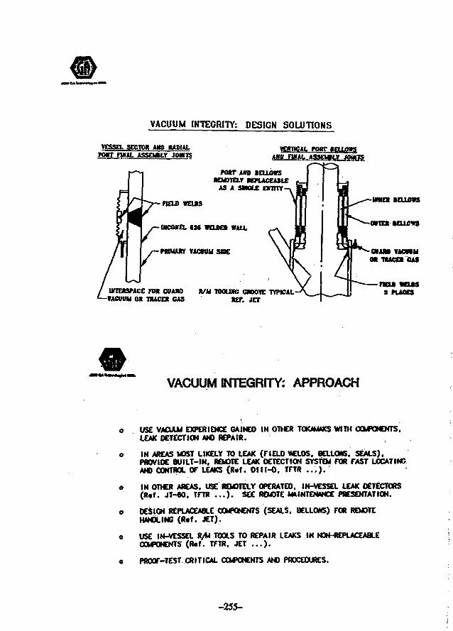
VACUUM INTEGRITY: DESIGN SOLUTIONS
VESSEL SECTOR AMD RADIALM I T flMAL ASSEf Vt J0WT5
fOHT BELLOWS
AND BELLOWSHEMDIELr KPUCEASLC
AS A SMOLC EHHTY
n a n WELDS
IMCONEL «3C WELOEB WALL
PRIMARY VACUUM SttK
INTERSPACE rat CUAHO « /M TOOLWC CMOVE TYPICAL-VACUUM OR TRACER CAS RET. JET
GUAM VACWIMOR TRACER CAS
TtOM WOJS3 PUCES
VACUUM INTEGRITY: APPROACH
USE VACUUM EXPERIENCE CA.INEO IN OTHER TOKAMAKS WITH COMMENTS.LEAK DETECTION AND REPAIR.
IN AREAS MOST LIKELY TO LEAK (FIELD VCLDS. BELLOM6. SEALS).PROVIDE BUILT-IN, REMOTE LEAK DETECTION SYSTEM FOR FAST LOCATINGAND CONTROL OF LEAKS (R«f. Olll-O. TFTR . . , ) •
IN OTHER AREAS. USE REMOTELY OPERATED. IN-VESSEL LEAK DETECTORS(R«f. JT-60. TFTR . . . ) • SEE REMOTE MAINTENANCE PRESENTATION.
DESIGN REPLACEABLE COMPONENTS (SEALS, BELLOWS) FOR REMOTEHANDLING (R«f. JET).
USE IN-VESSEL R/M TOOLS TO REPAIR LEAKS IN NON-REPLACEABLECOMPONENTS (R«f. TFTR, JET . . . ) .
PROOF-TEST. CRITICAL COMPONENTS AND PROCEDURES.
-255-
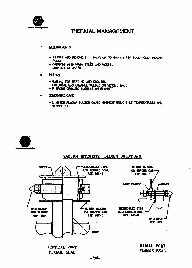
THERMAL MANAGEMENT
REQUIREMENTS
- ABSORB AND REMOVE IN 1 HOUR UP TO 800 MJ PER RJLL-PCMER PLASM*PULSE
- OPERATE WITH VWRM TILES AND VESSEL- BAKEOUT AT 350*C
- GAS N. FOR HEATING AND COOLING- POLOIQAL GAS CHANNEL WCLOED ON VESSEL WALL- FIBROUS CERAMIC INSULATION BLANKET
GOVERNING CASE
- LIMITER PLASMA PULSES CAUSE HIGHEST BULK TILE TEMPERATURES ANDVESSEL AT.
VACUUM INTEGRITY: DESIGN SOIUTIONS
COVER NEUCOFLEX TfPER/M BOVtLE SEAL
REF. MN-D
GUAM VACUUMOR UtACER GAS
RET. Dlll-D
PORT
GUARD VACUUMOR TRACER GAS
RET. M H O
PORT FLANGE
HEUCOfUX TYPER/M OOttlte SEAL
RET. Olll-DR/M BOLTRET. JET
VERTICAL PORTFLANGE SEAL
-256-
RADIAL PORTFLANGE SEAL
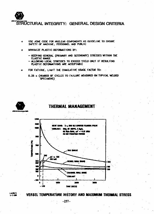
INTEGRITY: GENERAL DESIGN CRITERIA
USE ASME CODE FOR NUCLEAR COMPONENTS AS GUI DEL INC TO ENSURESAFETY OF MACHINE. PERSONNEL AND PUBLIC
MINIMIZE PLASTIC DEFORMATIONS BY:
- KEEPING GENERAL (PRIMARY AND SECONDARY) STRESSES WITHIN THEELASTIC RANGE
- ALLOWING LOCAL STRESSES TO EXCEED YIELD ONLY IF RESULTINGPLASTIC DEFORMATIONS ARE ACCEPTABLE
FOR FATIGUE. LIUIT THE CUMULATIVE USAGE FACTOR TO:
0-25 x (NUMBER OF CYCLES TO FAILURE MEASURED ON TYPICAL MCLOEDSPECIMENS)
THERMAL MANAGEMENT
O H
- 1 M Tim men
1-11-M VESSEL TEMPERATURE HISTORY ANO MAXIMUM THERMAL STRESS
-257-
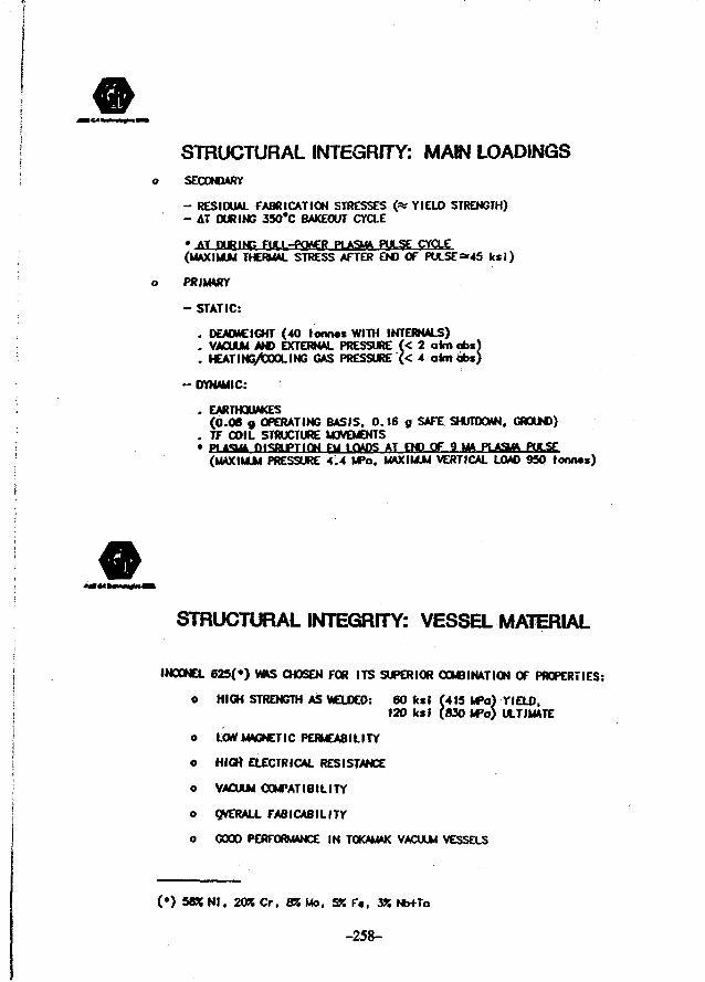
STRUCTURAL INTEGRITY: MAIN LOADINGSSECONDARY
- RESIDUAL FABRICATION STRESSES (% YIELD STRENGTH)- AT DURING 35O'C BAKEOUT CYCLE
» AT nURING FULI-POttER PLASMA PULSE CYCLE(MAXIMUM THERMAL STRESS AFTER END OF PULSE~45 ksi)
PRIMARY
- STATIC:
. DEADWEIGHT (40 tonn«s WITH INTERNALS)
. VACUUM AND EXTERNAL PRESSURE (< 2 aim abs)
. HEATING/tOOLING GAS PRESSURE (< 4 aim abs)
- DYNAMIC:
. EARTHQUAKES(0.08 g OPERATING BASIS, 0.16 g SAFE SHUTDOWN. GROUND)
. TF COIL STRUCTURE MOVEMENTS
(MAXIMUM PRESSURE 4.4 MPa, MAXIMUM VERTICAL LOAD 950 tonnas)
STRUCTURAL INTEGRITY: VESSEL MATERIAL
INOONEL 625(») VIMS CHOSEN FOR ITS SUPERIOR COMBINATION OF PROPERTIES:
o HIGH STRENGTH AS WELDED: 60 test (415 UPa) YIELD,
120 ksi (830 MPo) ULTIMATE
o LOW MAGNETIC PERMEABILITY
o HIGH ELECTRICAL RESISTANCE
o VACUUM COMPATIBILITY
o OVERALL FABICABILITY
o GOOD PERFORMANCE IN TOKAMAK VACUUM VESSELS
(*) 58% Nl. 20% Cr. SR Mo, ST. F«, 3K Nb+Ta
-258-

9 MA PLASMA DISRUPTIONS AT 0.7 MA/rus,WITH OOWNWARO PUSMA MOTION
MAWJNM STRESS—-2!tiiSMnC-7j iii tmume
NIWMAI ratssuaeMSTMWTW*AT 7.4 CM
surfnr
1-11-MMnuiswrc
^STRUCTURAL INTEGRITY: PLASMA DISRUPTION ANALYSIS
o VARIOUS DISRUPTION SCENARIOS WITH DIFFERENT CURRENT DECAY RATESAND PLASMA. MOTIONS STUDIED WITH TOKAMAK SIMULATION CODE (TSC)
o VESSEL LOAD HISTORIES GENERATED WITH ELECTROMAGNETIC PRESSURECODE (EMPRESS)
o STATIC. BUCKLING AND DYNAMIC ANALYSES OF VESSEL DONE WITH NASTRANCODE
o FINITE ELEMENT SHELL MOOELS OF 180-DEGREE AND 10-DEGREE SECTORSOF THE VESSEL WITH RADIAL PORTS USEO
-259-
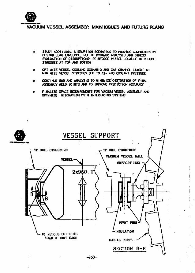
VACUUM VESSEL ASSEMBLY: MAIN ISSUES AND FUTURE PLANS
STUDY ADDITIONAL DISRUPTION SCENARIOS TO PROVIDE COMPREHENSIVEDESIGN LOAD ENVELOPE; REFINE DYNAMIC ANALYSIS AND STRESSEVALUATION OF DISRUPTIONS; REINFORCE VESSEL LOCALLY TO REDUCESTRESSES AT TOP AND BOTTOM
OPTIMIZE VESSEL COOLING SCENARIO AND GAS CHANNEL LAYOUT TOMINIMIZE VESSEL STRESSES DUE TO ATs AND COOLANT PRESSURE
CONTINUE R&D AND ANALYSIS TO MINIMIZC DISTORTION OF FINALASSEMBLY WELD JOINTS AND TO IMPROVE PREDICTION ACCURACY
FINALIZE SPACE REQUIREMENTS FOR VACUUM VESSEL ASSEMBLY ANDOPTIMIZE INTEGRATION WITH INTERFACING SYSTEMS
VESSEL SUPPORT
-TF COIL STRUCTURE
VESSEL
I F COIL STRUCTURE
VACUUM VESSEL WALL
SUPPORT UNK
18 VESSEL SUPPORTSLOAD - 106T EACH
PIVOT PINS-
-INSULATION
RADIAL PORTS
SECTION B-B
-260-
WRfcD
• THE WELDED JOINT RftD PROGRAM WAS RESUMED IN MAY 19M AND EXPANDED.IT INCLUDES:
- Vessel and radbl port final joint uniting tests - (GA. Edfeon WeWng Institute.Applied Fusion Technologies Inc.)
- Final wdd cleaning. NDT. repair development (FUTEC)
- Mechanical and low cydc fatigue testing of waldtrante (GA)
- Weld backing and vacuum leak control enamel development (GA)
- Wekfiog dbtortiun prtdktion (GA)
• PROTOTYPES OF VERTICAL PORT R/M FLANGES WITH DOUBLE METALLICVACUUM SEALS ARE BEING TESTED (HEUCOFLEX)
• TESTS BY GA HAVE SHOWN THAT THE THERMAL CONDUCTIVITY OF SUJCAFIBER INSULATING BLANKETS IS NOT AFFECTED BY IMMERSION IN LN3
JULY 1988 UPDATE2.1 m err
W DESIGN
• CONCEPTUAL DESIGN OF THE 2.1m VACUUM VESSEL BEING COMPLETED
• 2.1 m VESSEL STRESS ANALYSIS IN PROGRESS
- (Disruptions, temperatures); waN thfcknesses up to 3S in. (IS mm) locally art antici-pated
• MINIMUM VESSEL TEMPERATURE during plasma operation RAISED TO 330*C.
- The vessel heating and cooling conceptual design w « shown feasible.
« HAYNES ALLOY 230 (without Niobium) PROPOSED A» A LOW-ACTIVATION ALTER-NATE to Incond 625.
-261-
RRST WALL AND DIVERTOR DESIGN REQUIREMENTS
o PROTECT THE VACUUM VESSEL FROM LARGE ENERGY DEPOSIT IONS
o MINIMIZE PLASM IMPURITY LEVELS
- ALL SURFACES EXPOSED TO PARTICLE FLUX MUST BE CARBON
- ALL CARBON SURFACES MUST BE CAPABLE OF 3SO*C OUTOASSIMG
- MAXIMUM OPERATING TEMPERATURES < 2ZOO'C
o FIRST YMX AM) DIVERTOR ASSEMBLIES SHALL UE RADIATION/CONDUCTION
COOLED TO TIC VACUUM VESSEL
- ASSEMBLIES SHALL BE COOLED TO THEIR INITIAL TEMPERATURES
IN 1.0 HR
o ALL STRUCTURES MUST BE REMOTELY REPLACEABLE
COMPACT IGNITION TOKAMAK
FIRST WALL AND DIVERTOR
D. Leigh Sevier
J. Wesley
M. FisherG. Thurston
-262-
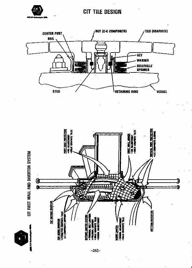
CIT TILE DESIGN
CENTER POST NUT (C-C COMPOSITE) /TILE (GRAPHITE)
STUD nETAWINO RING VESSEL
en
-263-
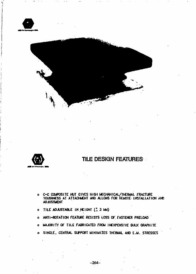
TILE DESIGN FEATURES
o C-C COMPOSITE NUT GIVES HIGH MECHANICAL/THERMAL FRACTURETOUGHNESS AT ATTACHMENT AND ALLOWS FOR REMOTE INSTALLATION ANDADJUSTMENT
o TILE ADJUSTABLE IN HEIGHT (1 3 MU)
o ANTI-ROTATION FEATURE RESISTS LOSS OF. FASTENER PRELOAD
o MAJORITY OF TILE FABRICATED FROM INEXPENSIVE BULK GRAPHITE
o SINGLE, CENTRAL SUPPORT MINIMIZES THERMAL AND E.M. STRESSES
-264-
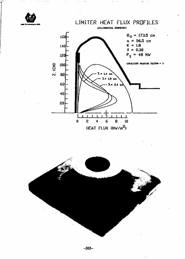
LIMITER HEAT FLUX PRDFILES(CYUMMICAL CCONCTKY)
Ro =173.5 ena = 56.5 enK = 1.8
0.38P t = 48 MV
LOULUU KAMNG FACTO*-- 2
0 3 4 6 8 10
HEAT FLUX (MV/n2)
-265-
WKIAIWW
K U t l W U
CIT DIVERTOR ASSEMBLY
5 , i5 , i « <• m •>•-« c« •• m •>.
TT7TT
I I i i § I
-266-
OBTAINING H-MODE
H-MODE OBTAINED INDIU-D. JET. AND JFT-2M WITHOPEN DIVERTOR.
CONFINEMENT QUALITY ADEQUATE (~ 2x KAYE-GOLDSTON)WITH OPEN DIVERTOR GEOMETRY
SINGLE-NULL WITH ION VB DRIFT INTO DIVERTOR YIELDSLOW H-MODE THRESHOLD; JON VB DRIFT AWAY FROMDIVERTOR CAN YIELD ENHANCED L-MODE.
DIVERTOR DESIGN CONSTRAINTS/REQUIREMENTS
• NO ACTIVE CQOUNG
• NO EXPOSED HIGH-Z MATERIAL
• MINIMUM HEIGHT
• REMOTELY MAINTAINABLE
« ACCOMMODATE PHYSICS DESIGN UNCERTAINTY
• PROVIDE OPERATIONS FLEXIBILITY
• SURVIVE OFF-NORMAL CONDITIONS
tflWM 4
-267-
MAXIMUM PIVERTOR TARGET POWER DENSITY
CONFIGURATION
DOUBLE NULL(U/D - 2:1)
SINGLE NULL
LOCATION
OUTSIDE
INSIDE
OUTSIDE
INSIDE
PHM (MW/m*)
37.4
11.1.
37.2
11.6
• WORST-;CASE (-20%) SCRAPE-OFF
• Dlll-D (DOUBLE EXPONENTIAL) PROFILE
• LONGER CONNECTION LENGTH OF SINGLE NULL (x 1.4)COMPENSATES FOR HIGHER POWER vs. DOUBLE NULL
OIVERTOR PHYSICS DESIGN PARAMETERS
PARAMETER
•UAH DURATION ( S )
FUSION FMCR (UK)
ALPHA POWER ( M 0
PLASM POHCR PARTITIONING (X P.)- FIRST M U (IWTROPIC)-DIVERWR
DIVCRTOR PWCR PMTITIOHINB (% P.)- OMMC0 PARTICLES- LOCALIZED MOIATIOH:
TO OIVOHOR TAflOCTTO OnCR SURFACES
DIVCRTOR UP/DWN POWER IALANCE (X P t l v )
OIVERTOR INSIOC/OUTSlOe POWER MLANCE ( X P | | ; ' )
ENERGY SCRAPE-OFr AT OUTSIDE MIDPLANE (<m)
INSIDE/DUTSIOE FLUX EXPANSION (AT MIDPLANE)
'WORST CASE DESIGN VALUES, NOT SIMULTANEOUS
OIVERTOR CONFIGURATION
OOUBLCNULL
S
300
W
2009
«O .
1010
*7/33
SS'/BO*
SINGLE NULL
S
300
CO
2080
60
1010
100/0
33775'
0.4«/O.«0/0.<4 O.72/0.9O/I.2*
1.S 1.5
-268- |VHIB<»»)>M
,-x/X
OIVERTOHTAROET
fl(. (. D«flnltlon of divtrtor m«y end profile p u m u n
P1VERTOR DESIGN CONCEPT
• OPEN GEOMETRY (NO BAFFLES)
• RELATIVELY SHORT DIVERTOR CHANNEL.(< 25 cm)
• PYROLYTIC GRAPHITE TARGETS. 6, ~ 90*
• MAGNETIC SWEEP OF STRIKE POINT TOSPREAD HEAT LOAD
lIMll f
-269-
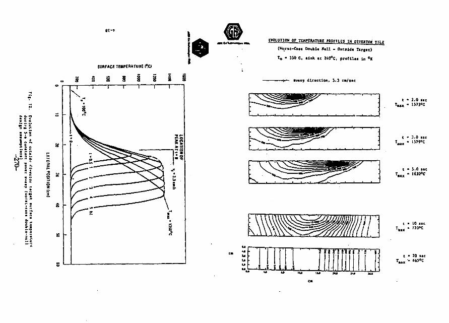
£ 2O r*
J
tl-7
SURFACE TEMfERATUBE I ' d
EVOLUTION OF TEHfEHATME fKQFIl.ES IN DtVEKTOK TII.r
(Iforsc-Cu* Doublt Hull - Oucildt T«r(fc)
To • 350 C, link. «c 240°C, p r o f l U t in °K
- » — tuttp d i rect ion. 3.3 ca/»tc
tttii > * '
t • 2.0 ttcX - 15?5»C
t • 3.0 ice
c • S.O ««c
t " 10 stc
c • 20 «cT . .x "" 6 6 5 ° c
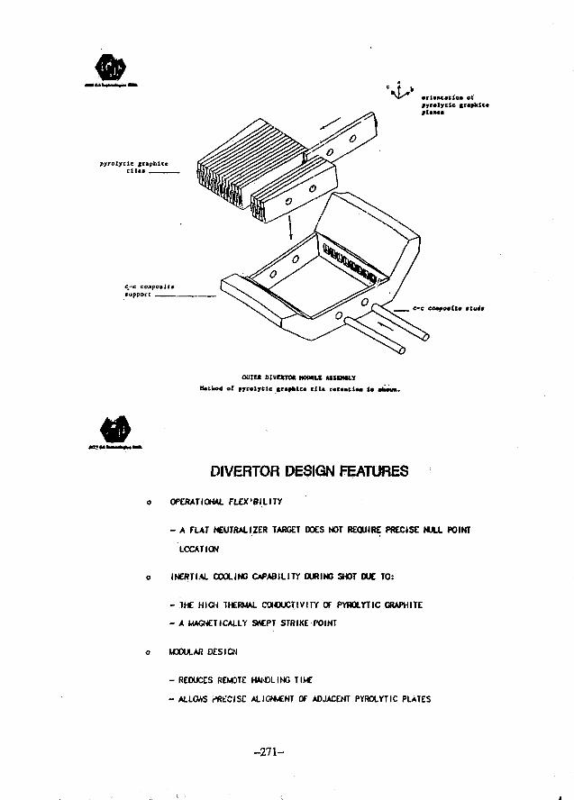
pyrolytlc jraphitctiles
c_-c compotlttsupport
•rlcfttacloii ox'pyrciycic graphictplane*
OUTER DIVERTO* HOtMILE ASSPWLY
Kctkod of pyrolycle s»pfcic< Clla r«c«nclM la
DIVERTOR DESIGN FEATURES
o OPERATIONAL flEX'BILITY
- A FLAT NEUTRAL IZER TARGET DOES NOT REQUIRE PRECISE NULL POINT
LOCATION
o INERT IAL COOLING OPA8ILITY DURING SHOT DUE TO:
- THE HIGH THERMAL CONDUCTIVITY OT PYROLYTIC GRAPHITE
- A MAGNETICALLY SrtCPT STRIKEfOINT
o MODULAR DESIGN
- REDUCES REMOTE HAMOLING TIME
- ALLOAS V'RfCISE ALIGNvCNT Of ADJACENT PYROLYTIC PLATES
-271-
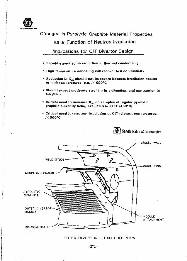
Changes in Pyrolytic Graphite Material Properties
as a Function of Neutron Irradiation
Implications for CIT Divertor Design
• Should expect some reduction in thermal conductivity
• High temperature annealing will recover lost conductivity
• Reduction in K.u should not be severe because irradiation occursat high temperatures, e.g. >1G00"C
• Should expect moderate swelling in c-direction, and contraction ina-b plane
• Critical need to measure I(al ] on samples of regular pyrolyticgraphite currently hcinrj irradiated iti FFTF (450°C)
• Critical need for neutron irradiation at CIT-rclcvant temperatures.
1 Sandra National Laboratories
MOUNTING BRACKET
PYROLITICGRAPHITE
OUTER DIVERTORMODULE
CC-COMPOSITE
VESSEL WALL
GUIDE PINS
MODULEATTACHMENT
OUTER DIVERTOR - EXPLODED VIEW
-272-
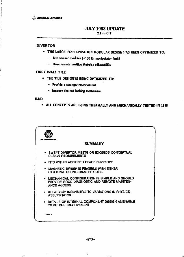
• CMMERML ATOMICS
JULY 1988 UPDATE2.1 m CIT
DIVERTOR
• THE LARGE. FIXED-POSITION MODULAR DESIGN HAS BEEN OPTIMIZED TO:
- Use smaller modules ( < 30 to. manipulator limit)
- Have remote position (height) adjustability
FIRST WALL TILE
• THE TILE DESIGN IS BEING OPTIMIZED TO:
- Provide a stronger retention hut
- Improve the nut locking mechanism
R&D
• ALL CONCEPTS ARE BEING THERMALLY AND MECHANICALLY TESTED IN 1988
SUMMARY
• SWEPT DIVERTOR MEETS OR EXCEEDS CONCEPTUALDESIGN REQUIREMENTS
• FITS WITHIN ASSIGNED SPACE ENVELOPE
• MAGNETIC SWEEP IS FEASIBLE WITH EITHEREXTERNAL OR INTERNAL PF COILS
• MECHANICAL CONFIGURATION IS SIMPLE AND SHOULDPROVIDE GOOD DIAGNOSTIC AND REMOTE MAINTEN-ANCE ACCESS
• RELATIVELY INSENSITIVE TO VARIATIONS IN PHYSICSASSUMPTIONS
• DETAILS OF INTERNAL COMPONENT DESIGN AMENABLETO FUTURE IMPROVEMENT
- 2 7 3 -
- { • • • ; — '11
1*'jtr
CIT ADJUSTABLE DIVERTOR MODULE
CtNtajU. MTOMICS
CIT FIRST WALL AND DIVERTOR R&D
1. Pyrolytic graphite tile high heat flux testing,(e-beam depositions up to 70 MW/nt3.)
2. First wall tile — tile and atUchment thermal and mechanical testing.(Ion beam depositions and vibration testing.)
3. ICRH Limiter tile and attachment.(Vibration testing.)
-275-
ITER FIRST WALL, DIVERTOR, AND VACUUM VESSEL
PRESENTED BY
J. R. HAINES
FUSION ENGINEERING DESIGN CENTER/McDONNELL DOUGLAS
AT THE
U.S.-JAPAN WORKSHOP ON VACUUM TECHNOLOGIES IN FUSiON DEVICES
IPP-NAGOYA UNIVERSITY
AUGUST 2, 1988
-276-
ABSTRACT
ITER FIRST WALL, DIVERTOR, AND VACUUM VESSEL
J. R. Haines
Recent efforts on the definition of the ITER first wall,divertor, and vacuum vessel have focussed on several key issuesincluding: (1) material selection; (2) heat flux and lifetimelimitations; and (3) integration of these components into theoverall reactor configuration. Carbon-based materials areconsidered the primary material candidate for plasma facingcomponents because of their extensive usage in existing tokaaaks,excellent thermal shock capability, and the high tolerance of theplasma to these lov-Z impurities. However, the rather limitedneutron damage and sputtering erosion lifetime of carbon-basedmaterials leads to the consideration of high-Z refractory metalssuch as W and Ta. it appears likely that carbon-based materialswill be used for both the first wall and divertor during theinitial physics phase of ITER operation. Perhaps during thesubsequent technology phase, a high-Z div.ertor plate materialwill be installed and tested.
The interaction of heat flux and erosion lifetimelimitations is receiving considerable attention in the ITERplasma facing component design activities. Based on studiescarried out in the U.S.., it appears to be possible to withstanddivertor plate heat fluxes approaching 10 HW/m2, The benefit ofsweeping the diverted plasma along the divertor plate and thustending to average the heat flux over a larger area is now underconsideration. ,
The ITER first wall structure will be constructed fromaustenitic stainless steel. Carbon-based armor will be used toprotect large portions of the first wall structure fromdisruptions, run-away electrons, and other forms of intenselocalized heating and particle impingement. This armor will bebaked at about 350°C to remove impurities before plasmaoperation. ,
The U.S. has proposed the use of a single vacuum vessel tosimplify construction and maintenance and to reduce the overallsize of the device. The key issues raised against the use of asingle vacuum wall are tritiun accumulation on the magnet cases,impurity backstreaiming to the plasma region and methods to handlethe plasma disruption induced eddy currents without a secondaryvacuum wall. Based on initial assessments, the use of a singlevacuum wall is a Viable option for ITER that should be exploredfurther to better quantify the advantages and disadvantages.
-277--
ITER MUST MAKE THE TRANSITION FROM PRESENT EXPERIMENTSTO FUTURE REACTORS
PRESENT EXPERIMENTS USE CARBON DIVERTOR TARGETS WITH CONFIDENCE
• CARBON HAS SHORT UFETIME DUE TO SPUTTERING EROSION AND NEUTRONDAMAGE, AND IS PROBABLY NOT REACTOR-RELEVANT
• HIGH-Z MATERIALS (W, Ta) APPEAR TO BE VIABLE CANDIDATES FORREACTOR APPLICATION
• ITER MUST TEST THESE CONCEPTS DURING THE ENGINEERING PHASE
USE C FOR PHYSICS PHASE; WHEN SPUTTERING AND IMPURITY TRANSPORT AREBETTER KNOWN, SWITCH TO W OR Ta
THE U.S. ITER ENGINEERING WORK ON PLASMA FACINGCOMPONENTS AND VACUUM VESSEL IS A TEAM EFFORT
• FIRST WALL AND DIVERTOR ENGINEERING
GAFEDCANLSNLLLNLLANLPPPL
• VACUUM VESSEL ENGINEERING
• FEDC• LLNL
-278-
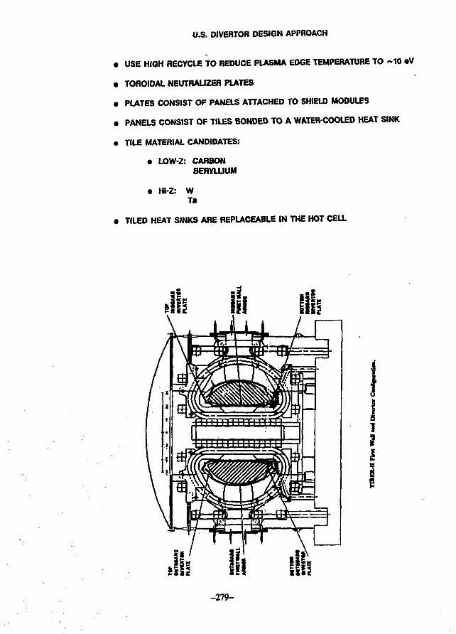
U.S. DIVERTOR DESIGN APPROACH
• USE HIGH RECYCLE TO REDUCE PLASMA EDGE TEMPERATURE TO ~10 «V
• TOROIDAL NEUTRAUZER PLATES
• PLATES CONSIST OF PANELS ATTACHED TO SHIELD MODULES
• PANELS CONSIST OF TILES BONDED TO A WATER-COOLED HEAT SINK
• TILE MATERIAL CANDIDATES:
• LOW-Z: CARBONBERYLLIUM
• Hl-Z: WT*
• TILED HEAT SINKS ARE REPLACEABLE IN THE HOT CELL
-279-
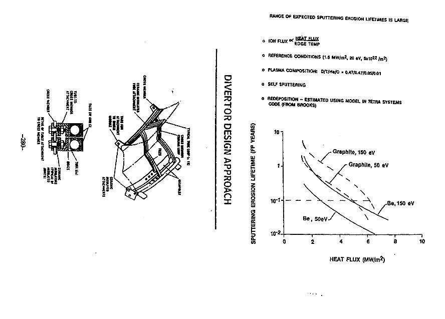
RANGE OF EXPECTED SPUTTERING EROSION LIFETIMES ISLARGE
<mTO
OTO
om(£en
oTO
§n
o REFERENCE CONDITIONS (1.5 MW/m*. 20 tV, 5x10« / m 2)
o PLASMA COMPOSITION: 0 /T/H* /0 • 0.47/0.47/0.05/0.01
o SELF SPUTTERING
o REDEPOSITION - ESTIMATED USING MODEL IN TETAA SYSTEMSCODE (FROM BROOKS)
Ul
O
55
gUJ
en
OL
101
10-1
10-2.
- Graphite, 150 eV
- Graphite,
Be, 150 eV
Be, SoeV
10
HEAT FLUX (MW/m*)
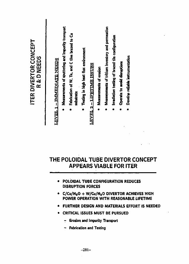
a.UJ
u
O
Q
LU
THE POLOIDAL TUBE DIVERTOR CONCEPTAPPEARS VIABLE FOR ITER
• POLOIDAL TUBE CONFIGURATION REDUCESDISRUPTION FORCES
• C/Cu/HaO + W/Cu/H30 DIVERTOR ACHIEVES HIGHPOWER OPERATION WITH REASONABLE LIFETIME
• FURTHER DESIGN AND MATERIALS EFFORT IS NEEDED
• CRITICAL ISSUES MUST BE PURSUED
- Erosion and Impurity Transport
- Fabrication and Testing
- 2 8 1 -
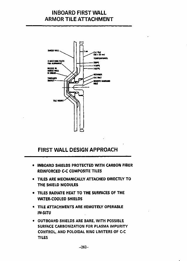
INBOARD FIRST WALLARMOR TILE ATTACHMENT
MKUWUl
FIRST WALL DESIGN APPROACH
• INBOARD SHIELDS PROTECTED WITH CARBON FIBER
REINFORCED C-C COMPOSITE TILES
• TILES ARE MECHANICALLY ATTACHED DIRECTLY TO
THE SHIELD MODULES
• TILES RADIATE HEAT TO THE SURFACES OF THE
WATER-COOLED SHIELDS
• TILE ATTACHMENTS ARE REMOTELY OPERABLE
IN-SITU
• OUTBOARD SHIELDS ARE BARE, WITH POSSIBLE
SURFACE CARBONIZATION FOR PLASMA IMPURITY
CONTROL, AND POLOIDAL RING LIMITERS OF C-C
TILES
-282-
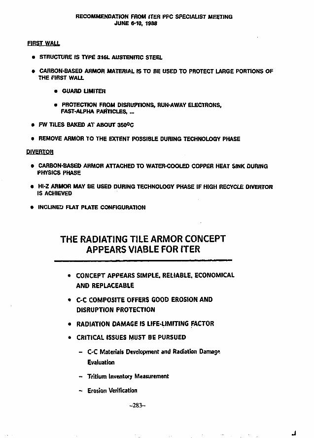
RECOMMENDATION FROM ITER PFC SPECIALIST MEETINGJUNE 6-10, 1988
FIRST WALL
• STRUCTURE IS TYPE 316L AUSTENITIC STEEL
• CARBON-BASED ARMOR MATERIAL IS TO BE USED TO PROTECT LARGE PORTIONS OFTHE FIRST WALL
• GUARD UMITER
• PROTECTION FROM DISRUPTIONS, RUN-AWAY ELECTRONS,FAST-ALPHA PARTICLES, ...
• FW TILES BAKED AT ABOUT 3S0°C
• REMOVE ARMOR TO THE EXTENT POSSIBLE DURING TECHNOLOGY PHASE
DIVERTOR
• CARBON-BASED ARMOR ATTACHED TO WATER-COOLED COPPER HEAT SINK DURINGPHYSICS PHASE
• Hl-Z ARMOR MAY BE USED DURING TECHNOLOGY PHASE IF HIGH RECYCLE DIVERTORIS ACHIEVED
• INCLINED FLAT PLATE CONFIGURATION
THE RADIATING TILE ARMOR CONCEPTAPPEARS VIABLE FOR ITER
• CONCEPT APPEARS SIMPLE. RELIABLE, ECONOMICAL
AND REPLACEABLE
• C-C COMPOSITE OFFERS GOOD EROSION AND
DISRUPTION PROTECTION
• RADIATION DAMAGE IS LIFE-LIMITING FACTOR
• CRITICAL ISSUES MUST BE PURSUED
- C-C Materials Development and Radiation Damage
Evaluation
- Tritium Inventory Measurement
- Erosion Verification
-283-
Single Vacuum Wall Concept for ITERAdvantages of a Single Vacuum Wall
• Simplicity in construction and maintenance
• Flexibility in the location of the passive loops
• Reduced radial build
• Enhanced impurity control
• Improved access to the magnet area
ITER VACUUM VESSEL
• VACUUM VESSEL CQNCEPT FOR ITER IS STSLL AN OPEN ISSUE
• SINGLE VACUUM WALL CONCEPT HAS BEEN PROPOSED BY THE U.S.
• DISCUSSIONS WERE HELD DURING ITER REACTOR CONFIGURATIONSPECIALIST MEETING HELD ON JULY 11-15.
- 2 8 4 -
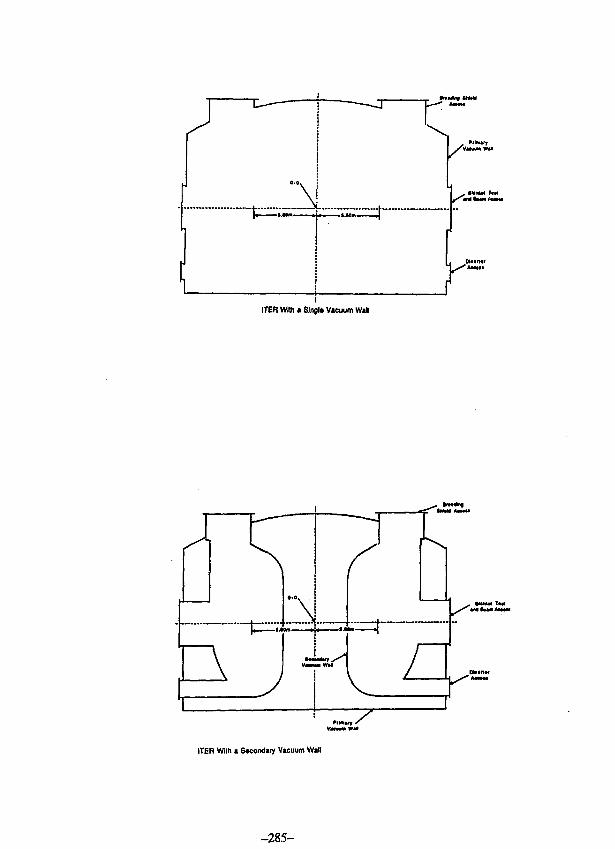
ITER With a Slngl* Vacuum Wai
: \
ITER With a Snondafy Vacuum Wall
-285-
Single Vacuum Wall Concept for ITER
Conclusions
• The use of a single vacuum wall is a viable option for ITER
that has several advantages
• Options should be kept open and explored for ITER
• All the "good ideas" have not been incorporated in anysingle design
Single Vacuum Wall Concept for ITER
Points raised against the use of a Single Vacuum Wallconcept for ITER
1 - How can the tritium accumulation on the magnetcases be limited to an acceptable level?
2 - How can impurity backstreaming to the plasmaregion from the magnet region be controlled?
3 - How does one handle the plasma disruption inducededdy currents without a secondary vacuum wall?
-286-
CONCLUDING REMARKS
• CARBON-BASED MATERIALS WILL BE USED EXTENSIVELY FOR ITER FW ANDDIVERTOR ARMOR
• AT LEAST DURING PHYSICS PHASE
• DESIGN WITH HIGH-Z DIVERTOR PLATE SURFACE WILL ALSO BE PURSUED
• POTENTIAL FOR LONG LIFETIME (REACTOR RELEVANT)
=3 • R&D EFFORTS SHOULD FOCUS ON:
• CHARACTERIZATION AND METHODS FOR CONTROUING PLASMAEDGE AND DISRUPTION CONDITIONS
• SELECTION OF "BEST1 CARBON-BASED AND HIGH-Z MATERIALS
• DESIGN EFFORTS SHOULD FOCUS ON:
• INTEGRATING DIVERTOR, FIRST WALL, AND VACUUM VESSELINTO OVERALL CONFIGURATION
• INCORPORATING DESIGN FEATURES WHICH MINIMIZE SENSITIVITYTO CHANGES IN PLASMA CONDITIONS AND GEOMETRY
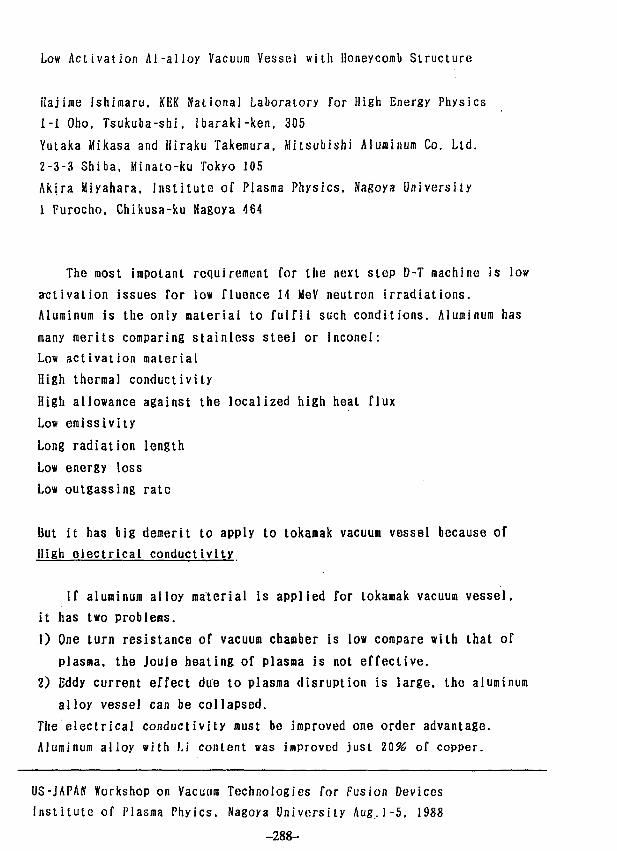
Low Activation Ai-alloy Vacuum Vessel with Honeycomb Structure
ilajirae Ishiraaru. KEK National Laboratory for High Energy Physics
1-1 Oho, Tsukuba-shi, Ibaraki-ken, 305
Yutaka Mikasa and Hiraku Takemura. Mitsubishi Aluminum Co. Ltd.
2-3-3 Shiba, Minato-ku Tokyo 105
Akira Miyahara, Institute of Plasma Physics, Nagoya University
1 Furocho. Chikusa-ku Nagoya 464
The most impolant requirement for the next step D-T machine is low
a-ctivation issues Tor low fluence 14 MeV neutron irradiations.
Aluminum is the only material to fulfil such conditions. Aluminum has
many merits comparing stainless steel or Inconel:
Low activation material
High thermal conductivity
High allowance against the localized high heal flux
Low emissivity
Long radiation length
Low energy loss
Low outgassing rate
But it has big demerit to apply to tokamak vacuum vessel because of
High electrical conductivity
If aluminum alloy material is applied for tokamak vacuum vessel,
it has two problems.
1) One turn resistance of vacuum chamber is low compare with that of
plasma, the Joule heating of plasma is not effective.
2) Eddy current effect due to plasma disruption is large, the aluminum
alloy vessel can be collapsed.
The electrical conductivity must be improved one order advantage.
Aluminum alloy with Li content was improved just 2 0 % of copper.
US-JAPAff Workshop on Vacuum Technologies for Fusion Devices
Institute of Plasma Phyics. Nagoya University Aug.1-5. 1988
-288-
New idea of honeycomb structure made of aluminum alloys using
vacuum brazing is proposed. One turn resistance along the toroidai
vacuum vessel is nearly same as stainless steel vessel, and the
effective eddy current due to plasma disruption is nearly.the same as
stainless steel case.
The honeycomb structure is double layer vacuum chambers. Safety
coverage against the tritium failure penetrating the inner layer is
available by evacuating the intermediate region.
The magnitude of the residual radioactivity is proportional to the
weight of material, the activity of honeycomb structure is about 1/10
of sol id aluminum alloy.
Aluminum honeycomb structure having same thickness with solid
aluminum alloy has nearly same mechanical strength for the solid
aluminum alloy. Keight of honeycomb structure is one tenth of solid
aluminum plate of the sane thickness, namely, electrical conductivity
of honeycomb structure is ten times of 'solid aluminum plate.
The unit of honeycomb structures is welded for toroidal assembly,
installation of some flange ports is electron beam welded.
Finite element analysis of honeycomb structure is needed for full size
torous.
Conclusion
The honeycomb structure of aluminum alloy with vacuum brazing
overcome the demerit of high conductivity of aluminum alloy and can be
applied for the tokamak vacuum vessel with D-T burning.
-289-
iti
Al is only the material which can be used as
rapid reduction of activities for low fluence
machine. It was already used for "TRISTAN"
colliding beam accelerator.
During It-Project design (1980-1984), strong
effort had been dedicated to develop low
conductivity Al-alloy for vacuum vessel of
tokamaks. But it was not completely succeeded.
Honeycomb structure is another approach to
reduce conductivity. Moreover, it lias less
activation comparing to the bulk material because
of reduction of weight.
Trial fabrication of torus vessel will be
presented.
CO
70
60
50
oD
X)Coo15o
oCD
Bxxx
30
20
Cu 10
l ~ ? x x x .Aluminum Alloy Series3~- 5 '• AIMg-Oi Alloys
A I M g l i AlloysA I L i M g Alloys
7X x x
3 E
5 -b
cc
1012152040
u
u
LU
Fig.
"0 100 200 300 400 500 600 700
Yield Strength (MPa)
1. Electrical conductivity vs. mechanical yield strength ofthe new alloys.
S T R E N G T H OF P A N E L
0) . M,A T E R I A L
1050 0Braziac Sheet T 1Filler Xclal(vilh efficiency)
Fablication of Curved PanelTS7 KB/.-
1 5 Ke/«9 KE/M
UOHOGEMUSPRESSURE
© BEND OK 300. PANEL
KUXI/X M.IMIKG OF PLATEPlate
Surface CorePlate Di.cnThickness Sion
1 h-152 M 51 h=2l2 b*201 h-312 h=3l
Mali aim T«ll SL1BAlmiiiuii T>2I SUBSUS T'U SUBSUS 7-21 SUB
Pressure
I Kr./cn *
1.030.660.22.13.09.06.52. 06SMM1.022
5I*/«"
5.143.31.10.640.450.32.60.3255.«Jft. 11
l.OKf/c.'
10.3{ .6
2.21.30.9.1.65:21.651.731.22
) Local Bending Of Surface Plate
1 h -152 h-151 h-202 . h=201 h-302 h-30
Prcxsurc] Il/ci'
0. 003C0.0004S0.0110. 00M0. OSS0.0072
0.0181.0231.0571.00731.21(.037
1 O U c i 'I .US0.11451.120.114I.5S0.172.
COIDc_o
o
o-MfDU
JDo
o
Variation of Flange
AL.
-292-
CD~iCDN!-•-—\
(Q
cIQ
Ui—<Q)ri~CD
ro CD
-29
r 00*~30)Nt-"
cin
1—*QJrt-CD
CO!-»•Q.CD
TDj — •0)ri-m
OO
ro
i—*QJf+fD
0)N
C(Q
CUN}->•
ZJIQ
O—h
TlI—'QJrt-
CD
Variation of FlangeFlat Flange
n
Squre Flange
o
0oo
O O O 0
o o o o
ooooo
o o o* 6 6~o0 O0 00 oO O O O O o
I.C.F. FLange (Plan)
2219 Core
Electron Beam Welding(After Brazed)
Aluminum sheet Brazing Sheet
Brazed aluminum
-294-
Particle balance of thermal neutralsin an ultrahigh vacuum system
measured by the Conductance Modulation Method
KTerada*, T.Okano*, and Y. Tuzf*
* Institute of Industrial Science, Univ. of Tokyo*' Ulvac Corporation
-295-
Contrary to the standardized scheme for the pumpingspeed measurement,conductance modulation method does notrequire absolute values of gas-throughput and pressureif the flow rate of gas kept constant, because thepumping speed is determined by the ratio of modulatedpressures correspond to the alternation of conductanceswith known values. This feature is useful for the speedmeasurement in ultimate pressure region of pumps wherethe decrement of throughput makes absolute measurementof the flow rate more difficult. Outgassing rate fromthe pump itself and the effect of the rate on thepumping speed can also be obtained by conductancemodulation method. In the present experiment, thepumping speed of a titanium getter pump was measured forhydrogen over wide pressure range. Vacuum chamber madeof stainless steal (450mm dia. x 500mm. 751) was pumpedthrough an orifice system by the liquid nitrogen cooledtitanium getter pump. The orifice system was composedof a fixed aperture and two discs which were moved upand down from the outside of the chamber. The conduct-ance values of the orifice system were calculated by theMonte Carlo method. The changes of the pumping charac-teristics of the titanium getter pump with the amount ofgases sorbed were measured and analysed.
-296-
SYSTEM A
(Fl f . l )Scheaallc dlacraas or l»o lelhods
of paaplac aaoed aeasarcaeiits.( •>rt i l rfoao aotftod . . (korlnd by
1SO/JIS.(•Kondactar.ce aod«Utl> aelhod!
(Fic.2)Scheaallc diagrsai of 1 M Hale
of conductance aodalation;A : Mck-coadtictacc position.B : LoH-condactace position.
(Flc.3)H1M4-HP asscably of aovsbl*
arlflea tystca.Oriflc* syilei l i A la Hi. I
it:
Ilium m
Hi
=
, -
Ha
= -
(Fli.OChancos of the proaswro in the test
doao correspond to the conversion oforifice t,ycloa at Q-const.
TIME-
C,. C, - MomoCanocac
(FU.5)Principle of the conductance
aodulatlon aclhod.
Requirements:
Sonswvllyofaauj* IO I consuntdmlngCMcyclcs
Ch • V.Jo W/r
c btlanea MUHV tysu
Sp: Hrtwlc pumping speed
5* :/no«surn]punvino speed
(Fle.6)Particle balance In UtIV syslca.
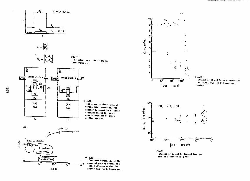
p.
P* 0, -0
s . -p.-p.
Hlaslrallo. of Ike f and S,
« 8 >Tke crost itctioa»l view of
»»cr i i t» l« l aptiratas. T««ckaaber Is paaptd *» • lla.aid«llro««« enlti Tl-f«ll«rrump throne" • • • of tk«s«or 1 Net t|p<««s.
(Fll.9)Prexsdcre dcre*d««c« of tkc
««as«rtd F«*9l*l speeds of al\**\i ul lrme. co*l<d Tl-cetler p«ap f*r kydrogen (as.
10 s 10' 10° Itf'
fodt IPa-n'l
( F f B . I O JChances of S,* *ni Sr «s jfunclion of
Ifio toUI «>oynl of hydroecn cassorbud.
Iff'!
o
o'
. Q:'
10"* 10"' 10"
fodi (Pirn')
( f i i . inCkan(«s of Op aad Q* deduced Troa thedal« ai af.ncllo. of { QH.
10"'
U.S.-Japan Workshop on Vacuum
Technologies for Fusion Device'
August 1-5,1988, IPP-Nagoya
D E S I G N AND O P E R A T I O N OF P E L L E T I N J E C T O R
August 2, 1988
T. U C H I K A W A
Mitsubishi Heavy Industries, Ltd.
-299-
JZ•o wc —ra H •
cc o ou — >
—. J_> y .« Q —O —« JS J
Su
bje
cts
in
c d
esi
gn
to
;
•Q C *J C
o « ra t.— • W M LC O 3 <1
.- i O —•
5 -o Q ra- C O " ^h» Q —. 4JQ t- SU • JD QL-• 3 ra » »
Q . O O *J• O fS -O —. O
3 • (- -Os « o e c o1 > w« U O - *
^1 — o: ra • « cit > O C» - * M4 *•> *Q <* —<
V >, - . t. O» o w o o *o
O. I- J=
—t « CJZ JJ *J o raM fl O «- >
-"* *- o ••<—I t* > ^t
a. = =
Abstract
Design and operation of pellet injector for JT-60 was
described with the detailed explanation of design features,
technical subjects in design and fabrication and subjects
to be solved in future.
-300-
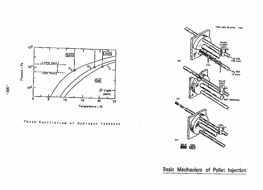
OHNL-0WC 6 0 . 2 H 6 F E 0
oT
I ' l i a s e l i q u i l i b r i u
24
m o f H y d r o g e n I s o t o p e s
He GAS(3Ooim)
Basic Mechanism of Pellet Injection
ORNL-DWG 85-3206 FED
PISTON SHAFT
LHt
PUNCH-TYPECHAMBERING
MECHANISM/BARRELCOMBINATION
11cm
Schematic of RPI-type Gun
HXJ
oa.
to
I5"•A
Pollet_carrier
Solenoid.valve
Propellent eas
Hydrogen gas
Schematic diagram of 4-pellet pneumatic injector
JFT-2MKU-:
JFT-2M Pellet Injector
-303-
m
- i rxV oO COto i
Diagnostics Platform Main Body of Pellet Injector
Gas Supply Panel
LHe Dewar
Low Vacuum Tank
Staging Structure
Schematic View of Pellet Injector installed on J T - 6 0
-304-
3.01—i—i—.—i—.—i—,—i—i—i—i—i—,—i—i—i—i—i—i—|—i—i—i—i—I 3.0
Ibkgf/cni
(j±) ORNL'.Oak Ridge National Lab.
4 S 8 10 12 14 16 18 20 22 24
C k m / s e e )
GunAs;sembly
JT-60
(HijhVac.ET) (LOWV«.ET)
GHe
Outline of Cryogenic, Gas and Exhaust System
-305-
fi-
•Ef
?T
ty}**.V.I-K
J7-«0 4-MUCT INJECFM MIUCU WlKKCt (TIIE-SOSCC) <KATO OVTO KEISMI I IK»E 112—Of-M.M)
Pressure Change of Each Vacuua Tank (t= 0-50 s)
I-
i;fX +
I-
I..2,
ri
I.W I.C2 0.0] 0.M O.0S ».0S 1.07 O.M
,JT-6> 4-FEU.ET lMJECfM SIINKU IHIKIIEI
t1*?-
SPikr
&
0 0.11 1.12 0.1) 0.14 I.IS
(me euro XEISAN I H»E HI—cx-it.ji)
Pressure Change of Each Vacuum Tank (t= 0-100 ms)
<ti.
-306-
PLASMA DRIVEN PERMEATION OF
HYDROGEN ISOTOPES
Y. FUJI I AND M. OKAMOTO
TOKYO INSTITUTE OF TECHNOLOGY
RESEARCH LABORATORY FOR NUCLEAR REACTORS
Deuterium permeation through an SS.304
membrane was studied under the condition of
a low temperature deuterium plasma generated
by RF heating.
Attention was placed on the effects of
bias potentials and on the correlation between
the permeation flux and the electric current
through the tested membrane.
Tritium permeation was observed by using
an ECR heating PDP experimental apparatus.
-307-
•A: Dlschargo Tubo(Pyrox)
B: Helical Anlonna
C: Probo Port
D: Capacitance Manometer
E: Pennlng's Gaugo
F: Doublo Probo
G: Connection Flange
H: Coramlc Tubo
I: Floxlblo Tubo
J: Glass Tube
I IK: Vacuum Chambor
L: Magnot(3OOgauss/25A)
M: Magnol(6OOgauss/25A)
N: Magnol(300gauss/25A)
Discharge Tube and Vacuum Chamber
un
RFGENERATOR
PULSEMODULATOR
LINEARAMPLIFIER
RF Generation System
-308-
AJ.1SN3Q N0H13313 AitSN3a
ELECTRON TEMPERATURE AND DENSITY VS. Dg GAS PRESSURE
RF Power:300V(eV) Magnetic Field : 600 gauss20
§ 10 _
(10llcm-3 )
10"* 10" 10"z
PRESSURE-309-
IO-1(Torr)
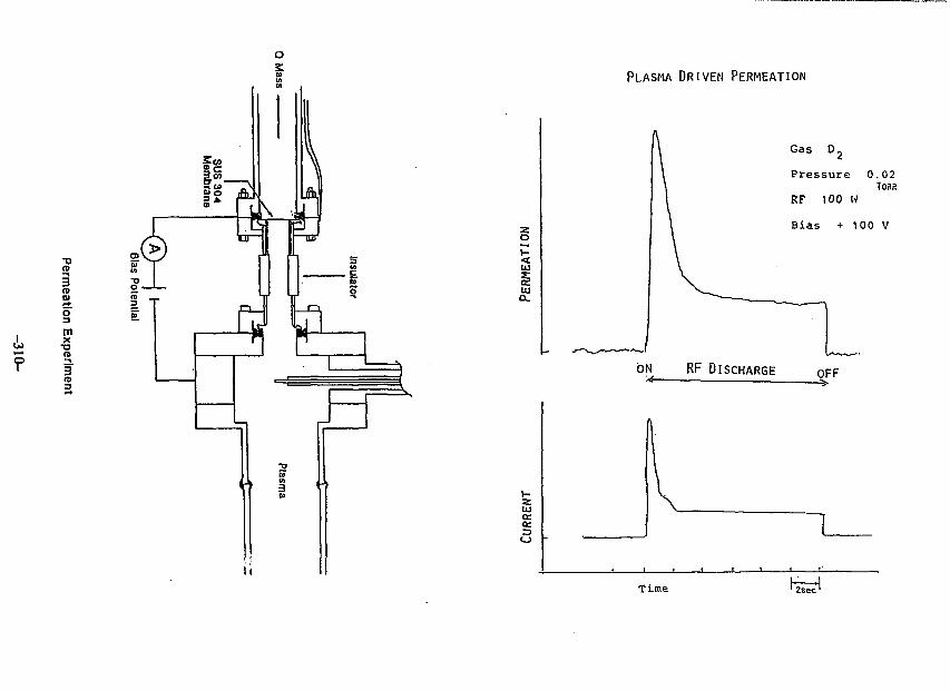
(S• n<t>D)r*
omx
•ara
• n
CD
PLASMA DRIVEN PERMEATION
iUI
Gas D2
P r e s s u r e 0 . 0 2TORR
RF 100 W
Bias + 100 V
UJen•=>
o
Time 2sec'
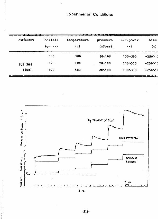
Experimental Conditions
Membrane
SUS 304
(40p)
M-field
(gauss)
600
600
600
temperature
<K)
380
480
580
pressure
(m'Jforr)
20-^100
20^,100
20^100
n.l?. power
(W)
100^300
100<\-300
100^300
bias
(v)
-250^12
-250^12
-250^12
TIME
- 3 1 1 -
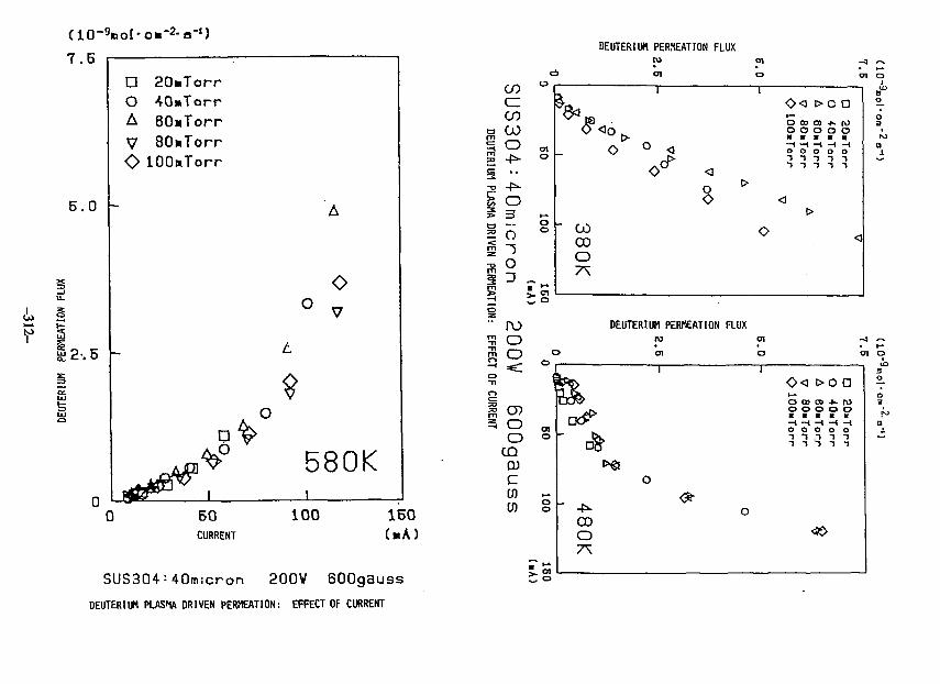
7 . 6
6.0 h
L 2
DOAVo
-
-
20«Torr40»Torr60»TorrdOmTorr
lOOaTorr
D 1
A
o° v
t
O
>
580Ki
50CURRENT
100 160
SUS304:40micron 200V 600gaussDEUTERIUM PLASMA DRIVEN PERMEATION: EFFECT OF CURRENT
DEUTERIUM PERMEATION FLUXto
oi
COdCOCO
o
% o? 3
1°m52
oD
T
o
>Q aO 00 CO + . fVJ
p p o o o0 o o o o1 "1 1 1 -It 1 T T T
COCDO
C o
rooo
DEUTERIUM PERMEATION FLUXro en
o
oo
CDDJCCDLO
eno
oo
OCX
480K
i
o
i
o
<>< >o ao CD co *. roo o o o o• T
orr
• Torr
• Torr
• Torr
iTorr
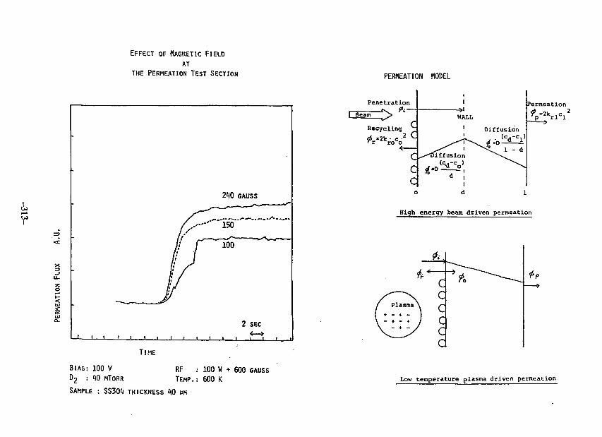
k
EFFECT OF MAGNETIC FIELD
AT
THE PERMEATION TEST SECTION
•
*( j
[•I:/>
/ • i
if
— ! ! 1 i i i
I
, i i
210
""l50
100
GAUSS_jt , , - -
->^N^j—^_
2 SEC
TIME
BIAS: 100 VD2 : 1)0 MTORR
SAMPLE : SS301 THICKNESS *t0 MM
RF : 100 W + 600 GAUSSTEMP.: 600 K
PERMEATION MODEL
Permeation
High energy beam driven permeation
cccccc
Low temperature plasma driven permeation
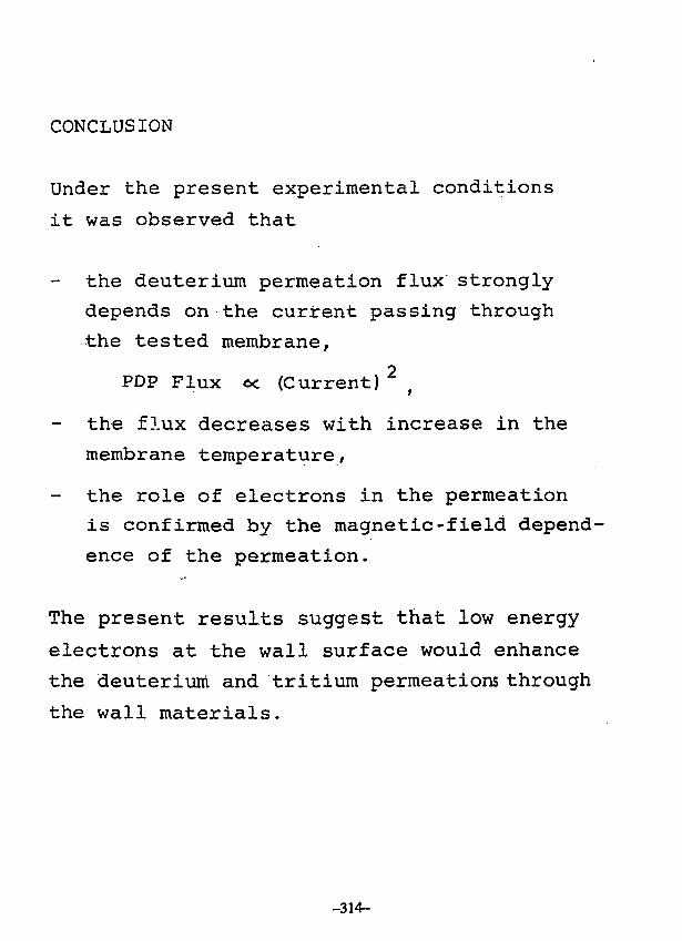
CONCLUSION
Under the present experimental conditions
it was observed that
the deuterium permeation flux strongly
depends on the current passing through
the tested membrane,
PDP Flux oc (Current)
the flux decreases with increase in the
membrane temperature,
the role of electrons in the permeation
is confirmed by the magnetic-field depend-
ence of the permeation.
The present results suggest that low energy
electrons at the wall surface would enhance
the deuterium and tritium permeations through
the wall materials.
-314-
Related Documents