Air humidification, dehumidification and evaporative cooling CONDAIR SOFT water softening system ASSEMBLY AND OPERATING INSTRUCTIONS Condair Soft water softening system 01.07.2021 20210701 EN

Welcome message from author
This document is posted to help you gain knowledge. Please leave a comment to let me know what you think about it! Share it to your friends and learn new things together.
Transcript

Air humidification, dehumidification and evaporative cooling
CONDAIR SOFTwater softening system
ASSEMBLY AND OPERATING INSTRUCTIONSCondair Soft water softening system 01.07.2021
2021
0701
EN
Property rightsThis document and the information contained herein are the property of Condair GmbH. Unless manufacturer approval has been granted in writing, the passing on and duplication of the manual (including extracts thereof) as well as the utilization and passing on of its contents to third parties are not permitted. Violations are punishable and result in an obligation to compensate for damages.
LiabilityCondair GmbH shall not be liable for any damage caused by faulty installation, improper operation, or by the use of components or equipment which are not approved by Condair AG.
Copyright noticeCopyright 2021, Condair GmbH, all rights reserved, subject to technical modifications
Thank you for choosing Condair
Installation date (DD/MM/YYYY):
Commissioning date (DD/MM/YYYY):
Installation site:
Model:
Serial number:
3
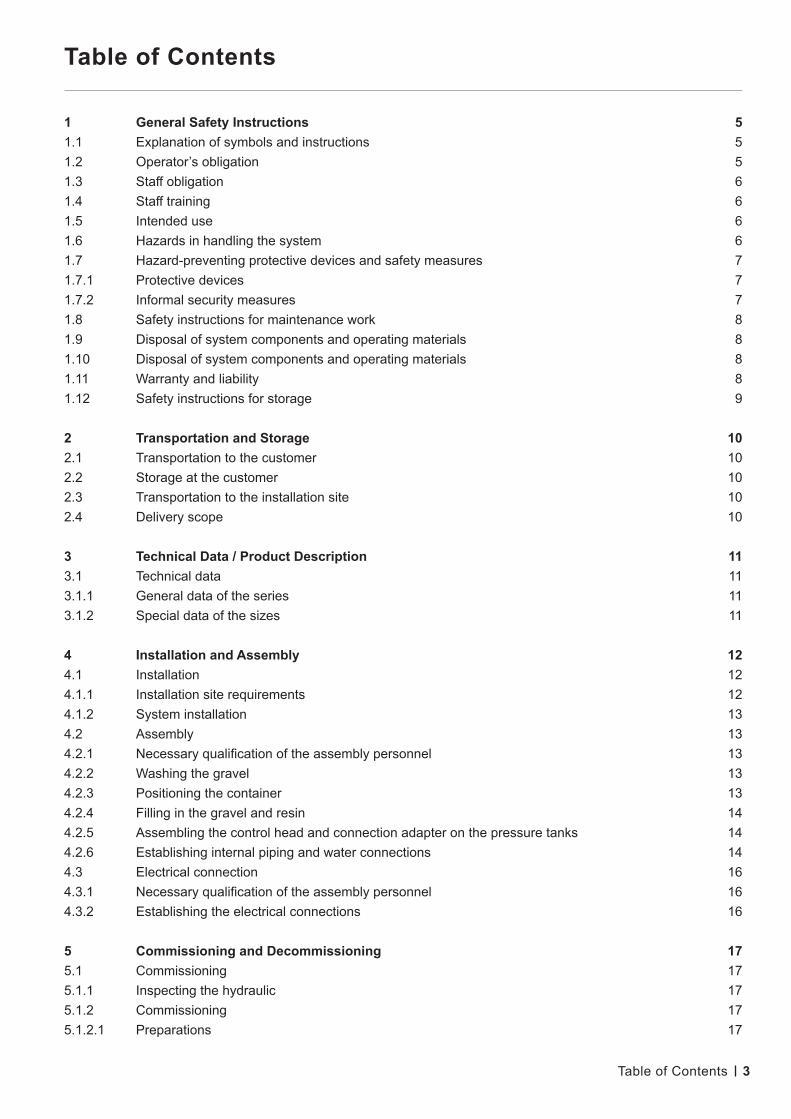
Table of Contents
1 General Safety Instructions 51.1 Explanation of symbols and instructions 51.2 Operator’s obligation 51.3 Staff obligation 61.4 Staff training 61.5 Intended use 61.6 Hazards in handling the system 61.7 Hazard-preventing protective devices and safety measures 71.7.1 Protective devices 71.7.2 Informal security measures 71.8 Safety instructions for maintenance work 81.9 Disposal of system components and operating materials 81.10 Disposal of system components and operating materials 81.11 Warranty and liability 81.12 Safety instructions for storage 9
2 Transportation and Storage 102.1 Transportation to the customer 102.2 Storage at the customer 102.3 Transportation to the installation site 102.4 Delivery scope 10
3 Technical Data / Product Description 113.1 Technical data 113.1.1 General data of the series 113.1.2 Special data of the sizes 11
4 Installation and Assembly 124.1 Installation 124.1.1 Installation site requirements 124.1.2 System installation 134.2 Assembly 134.2.1 Necessary qualification of the assembly personnel 134.2.2 Washing the gravel 134.2.3 Positioning the container 134.2.4 Filling in the gravel and resin 144.2.5 Assembling the control head and connection adapter on the pressure tanks 144.2.6 Establishing internal piping and water connections 144.3 Electrical connection 164.3.1 Necessary qualification of the assembly personnel 164.3.2 Establishing the electrical connections 16
5 Commissioning and Decommissioning 175.1 Commissioning 175.1.1 Inspecting the hydraulic 175.1.2 Commissioning 175.1.2.1 Preparations 17
Table of Contents

4
5.1.2.2 Set the control unit 175.1.2.3 Rinsing the filters 175.1.3 Establishing the operating state 185.2 Decommissioning 195.2.1 Short-term decommissioning (less than two weeks) 195.2.2 Long-term decommissioning (more than two weeks) 195.2.3 Recommissioning 195.2.3.1 Recommissioning after a short decommissioning period 195.2.3.2 Recommissioning after a long decommissioning period 20
6 Control Unit 216.1 Adjusting the control unit 216.1.1 Language, time and total hardness quick setting 216.1.2 Parameter setting 216.2 Operating displays 226.1.2 Parameter setting 226.3 Regeneration 226.3.1 Triggering immediate regeneration 226.3.2 Regeneration indicators 236.4 Power failure, notifications and faults 236.4.1 Power failure 236.4.2 Notifications 236.4.3 Faults 23
7 Faults and Fault Elimination 247.1 General instructions 247.1.1 Reporting faults to the manufacturer 247.1.2 Fault indication and reporting 247.2 Power failure, notifications and faults 25
8. Logging, Maintenance, Servicing 268.1 Testing, measuring, logging 268.2 Operating log 268.3 Maintenance 288.3.1 Maintenance check-list 288.3.2 Maintenance log 298.3.3 Recommendations 29
9. Appendix 309.1 Soft control head 309.3 Electrical connection 319.4 Soft control unit setting value 329.4.1 Soft 60 – Size adjustment 329.4.2 Soft 120 – Size adjustment 359.4.3 Soft 200 – Size adjustment 389.4.4 Soft 320 – Size adjustment 419.4.4 Soft 400 – Size adjustment 449.5 system dimensions 479.6 Assembly structure (diagram) 53
Table of contents
5
1. General Safety Instructions
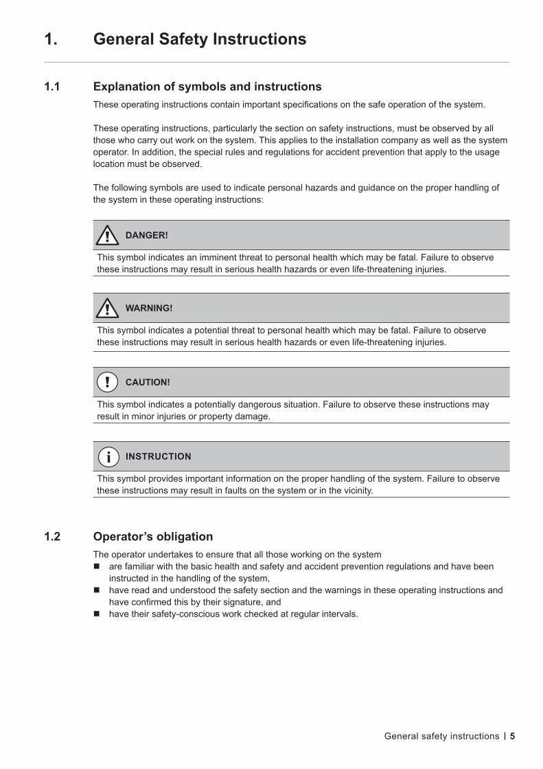
1.1 Explanation of symbols and instructions These operating instructions contain important specifications on the safe operation of the system.
These operating instructions, particularly the section on safety instructions, must be observed by all those who carry out work on the system. This applies to the installation company as well as the system operator. In addition, the special rules and regulations for accident prevention that apply to the usage location must be observed.
The following symbols are used to indicate personal hazards and guidance on the proper handling of the system in these operating instructions:
1.2 Operator’s obligation The operator undertakes to ensure that all those working on the system are familiar with the basic health and safety and accident prevention regulations and have been
instructed in the handling of the system, have read and understood the safety section and the warnings in these operating instructions and
have confirmed this by their signature, and have their safety-conscious work checked at regular intervals.
DANGER!
This symbol indicates an imminent threat to personal health which may be fatal. Failure to observe these instructions may result in serious health hazards or even life-threatening injuries.
WARNING!
This symbol indicates a potential threat to personal health which may be fatal. Failure to observe these instructions may result in serious health hazards or even life-threatening injuries.
CAUTION!
This symbol indicates a potentially dangerous situation. Failure to observe these instructions may result in minor injuries or property damage.
INSTRUCTION
This symbol provides important information on the proper handling of the system. Failure to observe these instructions may result in faults on the system or in the vicinity.
General safety instructions
6
1.3 Staff obligation Prior to commencing work, all individuals who are commissioned to work on the system or carry out
such work independently undertake to:
read the safety section and the warnings in these operating instructions and confirm by their signature that they have understood them.
observe the basic health and safety and accident prevention regulations.
When operating the system, the safety instructions must be strictly observed.
1.4 Staff training Only trained and instructed personnel may work on the system. The assembly, commissioning, operating, set-up, equipment, maintenance and servicing
responsibilities of the personnel must be clearly defined. Staff members who have not as yet been trained may only work on the system under the
supervision of an experienced co-worker.
1.5 Intended use The system may only be used for the desalination of drinking water, well water or surface water
which is free from particles and metal ions. The restrictions regarding the chemical analysis of the feed water, pressure, temperature and flow rate specified in the technical data apply.
Intended use also includes
observance of all instructions in the operating instructions and compliance with inspection and maintenance intervals.
The restrictions specified in the technical data apply with regard to the chemical analysis of the feed water, pressure, temperature and flow rate.
The following are also deemed non-intended use: utilisation as filter (mechanical filtration without regeneration with brine), storage tank (after removal of the ion exchanger material), pressure reservoir. Furthermore, hot water may not be fed into the system.
1.6 Hazards in handling the system The system has been designed and manufactured in accordance with the state of the art
and the recognised safety regulations. The system must be installed in such a way that the operating and control elements are
easily accessible at all times. The floor, ceiling and walls must be level and clean.
Nevertheless, its use may pose a health hazard to the user or third parties or put their lives at risk, or cause damage to the system itself or other property. The system is only to be used for its intended purpose (see 1.5) and in a safe condition.
The following residual hazards exist:
General safety instructions

7
Water damage
To prevent flooding due to leakage, the installation room must be equipped with a floor drain and/or a leakage monitor with a corresponding alarm.
Electric shock
Work on the electrical supply may only be carried out by a qualified electrician. Check the system’s electrical equipment on a regular basis. Any loose connections
or scorched cables must be removed immediately. The control cabinet must be kept locked at all times. Access is only granted
to authorized personnel. If work needs to be carried out on live parts, a second person must be called in
so that they can switch off the main switch as necessary. Do not touch the electrical components with wet hands. Disconnect the system from the power supply before working on electrical system parts.
Mechanical/hydraulic energy
Some system parts are under overpressure of up to 25 bar. The system must be de-pressurised before repair or maintenance work is carried out.
Hygienically critical applications
There is a risk of contamination of system components if the system has not been adequately preserved. The preservation instructions must be observed.
Faults which could impair safety must be rectified immediately. This is ensured by the operator himself or an operator-commissioned company.
1.7 Hazard-preventing protective devices and safety measures
1.7.1 Protective devices
Before switching on the system, all protective devices must be properly fitted and checked to ensure they are in working order.
Protective devices may only be removed after the machine has been switched off and secured against being switched back on.
The required personal protective equipment for the operating personnel must be provided by the operator and worn by the operating personnel when they are working on the system.
All existing protective devices must be checked regularly by the operator or an operator-commissioned company.
1.7.2 Informal safety measures
The operating instructions must be kept at the usage location permanently. In addition to the operating instructions, the generally applicable and local regulations
for accident prevention and environmental protection must be provided and observed. All safety and hazard notices on the system as well as the labelling of the operating
and control elements must be kept in legible condition.
General safety instructions

8
1.8 Safety instructions for maintenance work The operator must ensure that all maintenance, inspection and installation work is carried
out by authorised and qualified specialist personnel who have acquired the necessary information by studying the operating instructions.
Prior to all repair and maintenance work, the system must be switched off and secured against unintentional start-up. The procedure for shutting down the system described in the „Commissioning and Decommissioning“ section of the technical documentation must be observed at all times.
Before any work is started on the system’s electrical equipment, the corresponding section must be checked to ensure that it is not live. In addition, the system must be secured against being switched back on.
Suitable protective clothing appropriate to the hazard level in question must be worn while the work is being carried out.
Immediately after completion of the work, all safety and protective devices must be refitted or restarted.
The steps described in the „Commissioning and decommissioning“ section must be performed prior to recommissioning.
1.9 Disposal of system components and operating materials The system components must be disposed of, if necessary also separately, in accordance with
the local regulations.
1.10 Unauthorized modification and production of spare parts Conversion or modifications to the system are only permitted following consultation with
the manufacturer. This also applies to control unit program changes. Original manufacturer-authorized spare parts are used for safety purposes. If other parts are used, the warranty becomes void and no liability is accepted for the
resulting consequences.
1.11 Warranty and liability This product corresponds to the state of the art and has been designed, manufactured
and subsequently subjected to quality control in accordance with the applicable rules of technology. Should there nevertheless be cause for complaint, any claims for compensation against the manufacturer of this product are subject to the latter’s general terms and conditions of sale and delivery.
Warranty and liability claims for personal injury and property damage due to one or more of the following causes are excluded:
Improper use of the system Improper assembly, commissioning, operation and maintenance of the system Operating the system with defective safety devices or improperly installed or
non-functioning safety and protective devices Non-compliance with the instructions in the operating instructions regarding transport,
storage, installation, commissioning, operation (note: the operating log should be filled in on a continuous basis), and maintenance of the system.
Unauthorized, unapproved structural changes to the system Unauthorized modification of the control parameters Inadequate monitoring of system components that are subject to wear and tear Improperly performed repairs
Disasters caused by exposure to foreign bodies and force majeure.General safety instructions

9
1.12 Safety instructions for storage
CAUTION!
The water softening system is not protected against contamination by preservation upon delivery. In the case of long-term storage prior to system commissioning, the system must be preserved to prevent contamination. Please ask the system manufacturer about the possibilities of preservation. If the water softening system is stored in an area where there is a risk of frost, all residual water must be removed.
General safety instructions
10
2. Transportation and Storage
2.1 Transportation to the customer
The transport weight corresponds to the unladen weight and is specified in the technical data.
The system may still be damaged by extreme frost. The systems are filled with a preservative/antifreeze mixture before delivery. The frost protection is effective down to –10°C.
2.2 Storage at the customer
The maximum storage period of the original packed system is 3 months at 20 °C. The preservative must then be rinsed out and, if longer storage is desired, replenished.
Extreme frost may damage the system. The systems are filled with a preservative/antifreeze mixture before delivery. The frost protection is effective down to –10°C.
2.3 Transportation to the installation site
Transport the unit to the intended location with care using a suitable lifting vehicle. Observe any specifications relating to the system’s centre of gravity on the packaging.
2.4 Delivery scope
The system consists of:
2 exchanger tanks containing a central tube with lower slotted nozzle Ion exchanger (resin) for both filters and, if necessary, quartz gravel Control head for filter A and connection adapter for filter B, each equipped
with upper slotted nozzle Piping between filter A and B, hose material Brine tank with salt carrier bottom and brine valve
CAUTION!
All systems must be secured against slipping and falling over during transport. Allowing the system to tip out of the fixed stand is not permitted. If system parts are protruding from the base area of the pallet, such protruding parts must be protected against damage while other parts/ systems are being loaded.
Transportation and storage

11
3. Technical Data / Product Description
3.1 Technical Data3.1.1 General data of the series
3.1.2 Special data of the sizes
Technical data / Product description
Flow pressure min. bar 3Water pressure max. bar 8Water temperature, permissible °C 2 – 30Ambient temperature, permissible °C 5 – 40Raw and soft water connections R 1“Waste water connection, hose nozzle Ø (mm) 12Electrical connection, primary V/Hz 230 / 50Electrical connection, secondary V/Hz 24 / 50Current consumption, secondary mA 500
Type Condair Soft 60 120 200 320 400Capacity at full salting (m³ x °dH) 60 120 200 320 400Salt consumption with at full salting (kg) 3.0 6.0 10.0 16.0 20.0Resin volume (I) 2 x 15 2 x 30 2 x 50 2 x 80 2 x 100Gravel mass (kg) 1.2 4 4 8 11Nominal capacity (m³/h) 0.68 1.35 2.25 3.6 4.5Pressure drop at nominal capacity (bar) 0.3 0.4 1.0 1.33 1.73Short-term maximum output (m³/h) 1.0 1.5 2.5 4.0 4.5Waste water capacity, max. (m³/h) 0.30 0.62 0.62 0.96 1.20Pressure tank Ø (mm) 184 257 257 334 369Salt dissolving tank Ø (mm) 465 465 530 530 660Pressure tank height (mm) 903 903 1,380 1,381 1,660Salt dissolving tank height (mm) 673 673 1,047 1,047 990Unladen weight (kg) 60 95 135 210 270Operating weight (kg) 225 280 480 750 860Block dimensions W x D x H (mm) without brine tank
607 x 736x 1.063
647 x 726x 1.063
645 x 807x 1.540
827 x 839x 1.541
846 x 1043x 1.840

12
4. Installation and Assembly
4.1 Installation
4.1.1 Installation site requirements
The space required for the system is specified in the dimensions provided in the technical data.
The installation room must meet the ambient conditions according to the technical data. The installation surface must be level and horizontal and have sufficient load-bearing
capacity. The room must be well ventilated and frost-proof. The necessary electrical connections, as specified in the technical data, must be available
on-site at a maximum distance of 1 m from the system. Depending on the system size, a control air connection must be available. The raw water connection must be provided with a shut-off device. The on-site waste water connection must be provided as a free output in accordance with
EN 1717 and must be installed and usable in the required cross-section. Observe the waste water capacity specified in the technical data.
When using drinking water as the raw water of a softening system, the following must be observed:
An appropriately suitable fuse fitting for system separation must be installed by the customer on-site. Upon request, the manufacturer may add silver resin or supply a chlorine cell for installation in the brine exchange hose to enable automatic disinfection (subject to an extra charge).
WARNING!
To prevent flooding due to leakage, the installation room must be equipped with a floor drain and/or a leakage monitor with a corresponding alarm.
Technical Data / Product Description
INSTRUCTION
For installation and assembly, refer to the existing plans and drawings from the technical appendix.
INSTRUCTION
In accordance with EN 1717, softening systems may be equipped with the following safety fittings in drinking water installations: free output or pipe isolator. It should also be noted that DIN 19636 „Softening systems in drinking water installations“ requires the following – page 2, point 4.7 Protection against germs: „Since softening systems tend to become contaminated, especially in stop-start operation, this must be prevented by means of suitable design or chemical-physical measures.“
13
4.1.2 System installation
Unpacking the system Check the delivery to ensure it is complete and free from transport damage.
Transport the system to the intended location with care using suitable lifting equipment.
The installation is carried out on an installation surface in accordance with the requirements above.
4.2 Assembly4.2.1 Necessary qualification of the assembly personnel
4.2.2 Washing the gravel
Systems of the sizes 60 to 200 are already filled with supporting gravel upon delivery. For systems of size 320 and larger, proceed as follows:
To remove impurities, wash the supplied quartz gravel in a bucket under running water, stirring constantly.
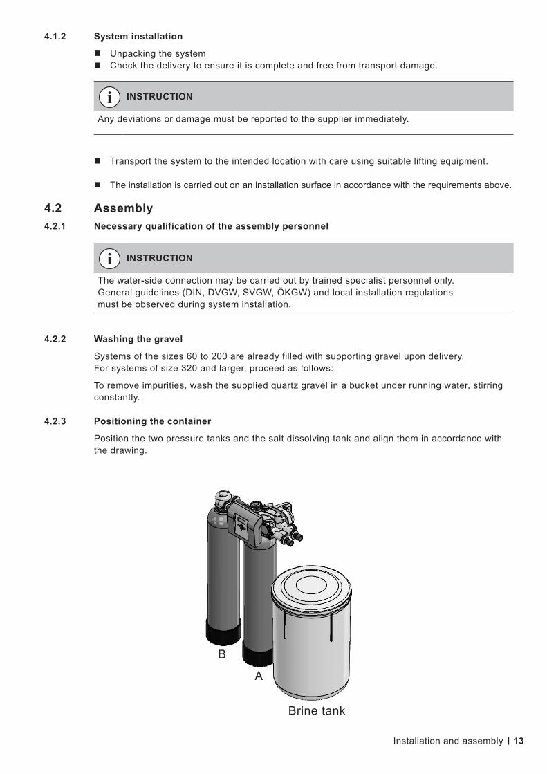
4.2.3 Positioning the container
Position the two pressure tanks and the salt dissolving tank and align them in accordance with the drawing.
INSTRUCTION
Any deviations or damage must be reported to the supplier immediately.
Installation and assembly
INSTRUCTION
The water-side connection may be carried out by trained specialist personnel only. General guidelines (DIN, DVGW, SVGW, ÖKGW) and local installation regulations must be observed during system installation.
B
A
Brine tank
14
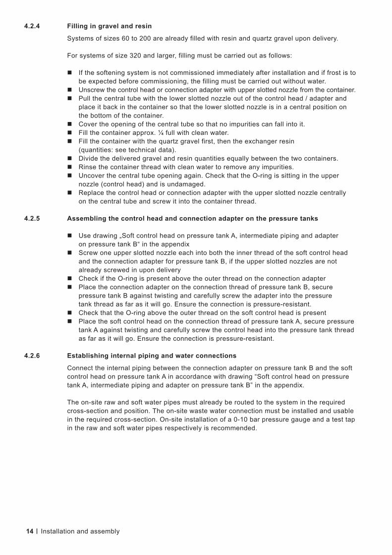
4.2.4 Filling in gravel and resin
Systems of sizes 60 to 200 are already filled with resin and quartz gravel upon delivery.
For systems of size 320 and larger, filling must be carried out as follows:
If the softening system is not commissioned immediately after installation and if frost is to be expected before commissioning, the filling must be carried out without water.
Unscrew the control head or connection adapter with upper slotted nozzle from the container. Pull the central tube with the lower slotted nozzle out of the control head / adapter and
place it back in the container so that the lower slotted nozzle is in a central position on the bottom of the container.
Cover the opening of the central tube so that no impurities can fall into it. Fill the container approx. ¼ full with clean water. Fill the container with the quartz gravel first, then the exchanger resin
(quantities: see technical data). Divide the delivered gravel and resin quantities equally between the two containers. Rinse the container thread with clean water to remove any impurities. Uncover the central tube opening again. Check that the O-ring is sitting in the upper
nozzle (control head) and is undamaged. Replace the control head or connection adapter with the upper slotted nozzle centrally
on the central tube and screw it into the container thread.
4.2.5 Assembling the control head and connection adapter on the pressure tanks
Use drawing „Soft control head on pressure tank A, intermediate piping and adapter on pressure tank B“ in the appendix
Screw one upper slotted nozzle each into both the inner thread of the soft control head and the connection adapter for pressure tank B, if the upper slotted nozzles are not already screwed in upon delivery
Check if the O-ring is present above the outer thread on the connection adapter Place the connection adapter on the connection thread of pressure tank B, secure
pressure tank B against twisting and carefully screw the adapter into the pressure tank thread as far as it will go. Ensure the connection is pressure-resistant.
Check that the O-ring above the outer thread on the soft control head is present Place the soft control head on the connection thread of pressure tank A, secure pressure
tank A against twisting and carefully screw the control head into the pressure tank thread as far as it will go. Ensure the connection is pressure-resistant.
4.2.6 Establishing internal piping and water connections
Connect the internal piping between the connection adapter on pressure tank B and the soft control head on pressure tank A in accordance with drawing “Soft control head on pressure tank A, intermediate piping and adapter on pressure tank B” in the appendix.
The on-site raw and soft water pipes must already be routed to the system in the required cross-section and position. The on-site waste water connection must be installed and usable in the required cross-section. On-site installation of a 0-10 bar pressure gauge and a test tap in the raw and soft water pipes respectively is recommended.
Installation and assembly

15
Brine line:
Use the brine line to connect the injector at the control head with the brine valve in the brine tank (PE hose).
Raw water connection:
Connect the raw water pipe to the raw water connection via the on-site shut-off valve.
Soft water connection:
Connect the soft water connection to the consumer(s).
Waste water connection:
Route the rinsing output of the control head and the overflow connection of the brine tank to the free input in the waste water connection by means of one fabric hose respectively.
INSTRUCTION
All pipe connections must be connected when the system is not live. Ensure that no squeezing or kinking of the hoses occurs and screw hose connections tightly. The concentrate and drain lines must be routed with a downward slope to the free wastewater input. The waste water must be allowed to flow off without backpressure.
Installation and assembly
INSTRUCTION
Negative pressure must not be generated in the exchanger tank or other components of the softening system under any circumstances. If necessary, an additional ventilation valve to prevent negative pressure must be installed on-site.

16
4.3 Electrical connection4.3.1 Necessary qualification of the assembly personnel
4.3.2 Establishing the electrical connections
The internal system modules are already wired to the control unit upon delivery. The power supply to the control unit is provided by the cable that is permanently
connected to the control unit with the integrated 230V-50Hz/ 12V-50Hz AC-AC adapter. The control unit’s current consumption with the system‘s connected internal actuators is
500 mA. An AC earthed socket (type CEE 7/3) fused in accordance with the system output must be
assembled within reach of the control unit connection cable’s length. Then, insert the plug of the control unit’s power supply cable into the socket.
One output each is available on the control unit for the signalling of a regeneration (RLY1) and of an internal control error (RLY2) to the ZLT, (labelled RLY1 and RLY2 respectively at the right edge of the board).
Installation and assembly
DANGER!
The electrical installation must be carried out by a qualified electrician, in compliance with the VDE and EVU installation regulations, factory standard, etc. and in accordance with the valid country-specific regulations.
DANGER!
The electrical installation must be carried out by a qualified electrician, in compliance with the VDE and EVU installation regulations, factory standard, etc. and in accordance with the valid country-specific regulations.
This involves two live NO contacts with a joint 12VDC conductor (COM), with an authorised load of 100mA per output. The total current of both outputs must not exceed 200mA. If potential-free signal outputs are required, the on-site installation of two cut-off relays with 12 VDC/max. 100 mA is recommended. Check the installation dimensions of the relays before assembling them under the control cover.
17
5. Commissioning and Decommissioning
5.1 Commissioning5.1.1 Inspecting the hydraulic
connections before commissioning:
Are the raw, soft, waste, brine and overflow lines properly connected and tight? Is sufficient flow pressure available at max. capacity? (See technical data in section C)
Electrical connections:
Is an earthed socket output assembled within reach of the mains connection cable and is it permanently live? Is the water meter sensor plugged into the control unit?
5.1.2 Commissioning
Check the system for leaks during commissioning. Leaks may occur during transportation, which need to be rectified during commissioning.
5.1.2.1 Preparations
Close the on-site shut-off valves upstream and downstream of the softening system Plug the mains adapter into the shockproof socket
5.1.2.2 Set the control unit
Read section F (control unit) of these operating instructions and the control unit programming instructions in the appendix carefully before commissioning.
The control unit is largely pre-set at the factory. Check the control unit settings using the programming instructions for the applicable size 60, 120, 200, 230 or 400 in the appendix and adjust the quick setting special values, which depend on the local conditions (e.g. raw water hardness).
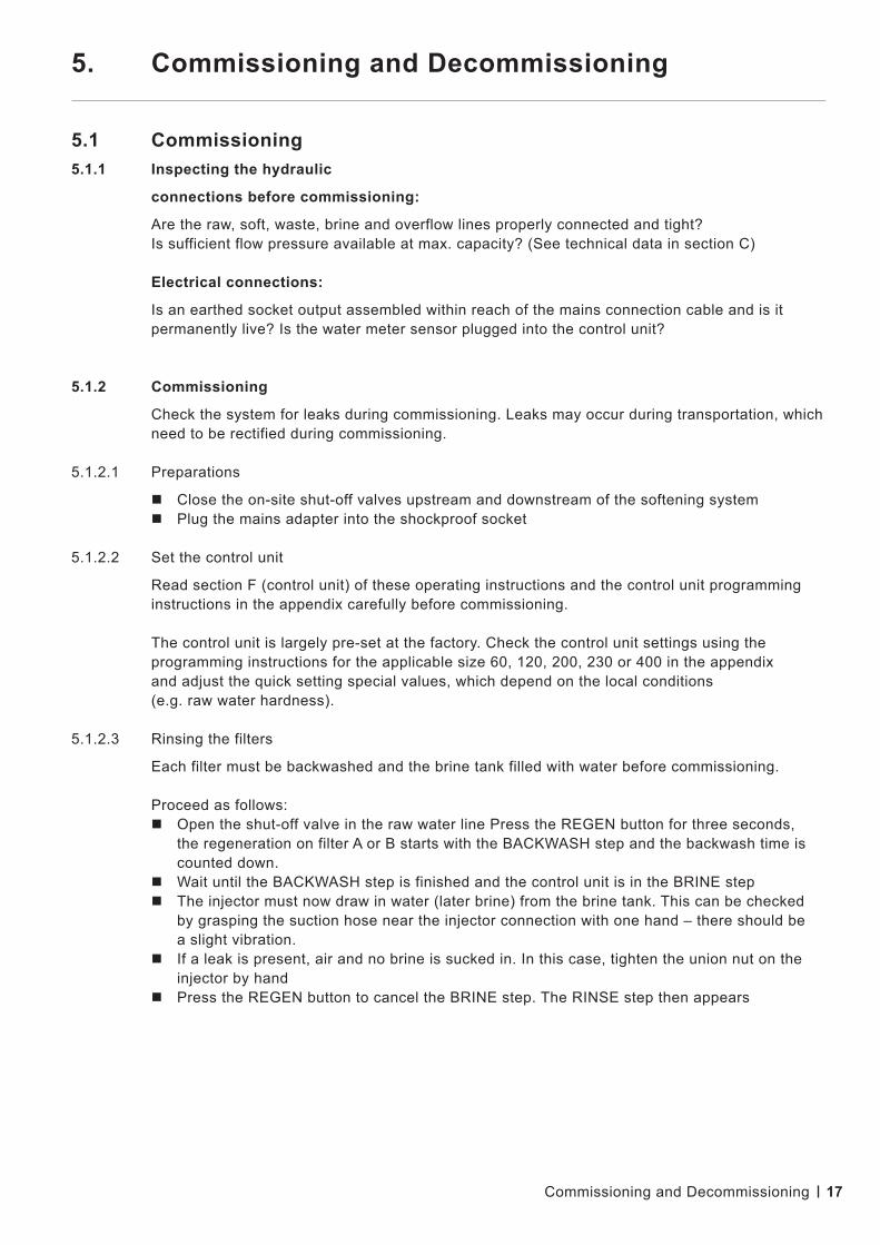
5.1.2.3 Rinsing the filters
Each filter must be backwashed and the brine tank filled with water before commissioning.
Proceed as follows: Open the shut-off valve in the raw water line Press the REGEN button for three seconds,
the regeneration on filter A or B starts with the BACKWASH step and the backwash time is counted down.
Wait until the BACKWASH step is finished and the control unit is in the BRINE step The injector must now draw in water (later brine) from the brine tank. This can be checked
by grasping the suction hose near the injector connection with one hand – there should be a slight vibration.
If a leak is present, air and no brine is sucked in. In this case, tighten the union nut on the injector by hand
Press the REGEN button to cancel the BRINE step. The RINSE step then appears
Commissioning and Decommissioning

18
To cancel the RINSE step, press the REGEN button. The FILL (brine tank) step appears Wait for this step Rinse the second filter by proceeding as described above for the first filter. After completing the FILL step, check whether the water in the brine tank is at
least approx. 20 mm above the salt carrier bottom or higher (visible through the semi-transparent container wall).
The water should be at least approx. 20 mm above the salt carrier bottom after the second regeneration run. Otherwise, check the parameter settings of the control unit, where Step 14 „Filling quantity“, must be set correctly. After correcting the „Filling quantity“ parameter, following the specifications in the appendix, start another regeneration and proceed as described above once again until the „Fill“ step is completed.
5.1.3 Establishing the operating state
Fill the brine tank with the regenerating salt and distribute it evenly on the salt carrier bottom
Open the shut-off valves in the raw and soft water lines so that water can be drained Throttle the soft water quantity at the soft water shut-off valve so that the max. flow rate
is not exceeded. Otherwise, the system will be hydraulically overrun, which may result in a residual hardness increase. In the absence of a flow or quantity indicator, the flow rate must be determined by gauging.
Commissioning and Decommissioning
INSTRUCTION
Only evaporated salt as per DIN EN 973 is suitable for regeneration. Exclusive use of tablet salt of higher purity according to DIN EN 973, type A is recommended.
INSTRUCTION
The flow rate limitation must not be carried out in the raw water pipe, otherwise not enough water can be drained for regeneration.
INSTRUCTION
When using fine-grained evaporated salt, a gauze cloth (mesh size 200 μm), cut to size, must be placed on the salt carrier bottom. The gauze cloth must cover the entire salt carrier bottom with no gaps, be guided upwards along the container walls and be held in place by throwing it over the container collar before securing the lid.

19
5.2 Decommissioning5.2.1 Short-term decommissioning (less than two weeks)
It is essential to wait until any ongoing regeneration has been completed. Otherwise, there is a risk that hardness or even brine will be fed into the system during recommissioning.
Pull out the mains plug Close the shut-off valves in the raw and soft water lines If a supply to the downstream consumers is required, including a raw water supply, open the
bypass line (if available).
5.2.2 Long-term decommissioning (more than two weeks)
The softening system (both filters) must be completely regenerated before it is decommissioned for a longer period of time.
To trigger a regeneration, press the REGEN button for at least 3 s (the first of the two filters is now regenerated) and wait for it to be completed.
Wait at least 5 hours (at min. 15°C) until new brine has formed in the brine tank Trigger another regeneration by pressing the REGEN button for at least 3 s
(the second of the two filters is now regenerated) and wait for it to be completed. After regeneration has been completed, pull the mains plug out of the socket. If the softening system is at risk of frost during the decommissioning period, the water
must be removed from the filter. The residual moisture in the filter is sufficient to prevent the resin from drying out. In this state, the resin can tolerate frost down to –10°C without being damaged.
5.2.3 Recommissioning
5.2.3.1 Recommissioning after a short decommissioning period
Check that the softening system and all hydraulic connections are in proper working order, and that the salt dissolving tank is completely filled with regenerating salt
Plug in the mains plug Slowly open shut-off valves in raw and soft water lines
Commissioning and Decommissioning

20
5.2.3.2 Recommissioning after a long decommissioning period
After a long decommissioning period, regeneration combined with resin disinfection must be carried out before the system can be recommissioned. For the disinfection, we recommend Lubron disinfection tabs (DesiTabs).
Check that the softening system and all hydraulic connections are in proper working order and the salt dissolving tank is completely filled with regenerating salt
Using a hose, fill the salt dissolving tank with water from an external supply until the water is above the salt carrier bottom (salt is in contact with the water, brine formation is enabled)
Before regeneration, wait at least 5 hours (at min. 15°C) for brine to form (starting from the last regeneration or fill of regeneration salt)
Drop DesiTab tablets (number of tablets according to the instructions enclosed with the tablets) into the brine standpipe and wait 10 min.
Plug in the mains plug Open the shut-off valve in the raw water line Press the REGEN button for three seconds, the regeneration on filter A or B starts
with the BACKWASH step and the backwash time is counted down. Wait until the BACKWASH step has been completed and the control unit is in the
BRINE step Observe the brine disinfectant solution mixture soaking in. At a solution level of approx. 70
mm in the brine tank, when nothing more is being sucked in, close the shut-off valve in the raw water line and disconnect the control unit plug
Wait approx. 30 minutes, then reconnect the control unit plug Slowly open the raw water ball valve and allow the regeneration to run until it finishes. The
brine tank is then refilled with water and new brine is formed. Wait at least 5 hours (at min. 15°C) until new brine has formed in the brine tank Trigger another regeneration by pressing the REGEN button for at least 3 s and repeat
this procedure for the second filter. If filter A was regenerated previously, the regeneration starts at filter B and if filter B was regenerated previously, the regeneration starts at filter A
After both filters have been regenerated in the manner described here, which includes disinfection, the system is available for the production of soft water once more.
Slowly open the shut-off valves in the soft water line.
Commissioning and decommissioning

21 Control unit
6. Control Unit
6.1 Adjusting the control unit6.1.1 Language, time and total hardness quick setting
Proceed as shown in the following table:
6.1.2 Parameter setting
The setting
of cycles (regeneration process) and parameters
is a necessary prerequisite for the correct operation of the system. The control unit is preset ex-works to match the size. Check all settings and use the corresponding size-specific tables in the appendix. These tables contain all the values to be set, including the quick setting from section 1.1.
Step Operation Display content
Starting pointTime of day (for example)A 7:35
01Press CLOCK briefly, hour flashes Set with ▼ or ▲
HourSet 8:35
02 Press NEXT briefly, minute flashes Set with ▼ or ▲
HourSet 08:40
03 NEXTTime of day (for example)A 8:40
04 NEXT + ▲ press together and hold briefly
GermanSet Language
05 NEXT + ▼ or ▲Input hardness (measured value, for example)Set 20°dH
06 NEXT + ▼ or ▲Residual hardnessSet 0°dH
07 NEXT + ▼ or ▲Days between two regenerationsSet 3
08 NEXTTime of day (for example)A 8:41

22
6.2 Operating displays Operating displays appear in black letters on a blue background.
6.1.2 Parameter setting
The setting
of cycles (regeneration process) and parameters
is a necessary prerequisite for the correct operation of the system. The control unit is preset ex-works to match the size. Check all settings and use the corresponding size-specific tables in the appendix. These tables contain all the values to be set, including the quick setting from section 1.1.
6.3 Regeneration6.3.1 Triggering immediate regeneration
Press the „REGEN“ button for at least 5 seconds.
The control unit sets the currently operational valve at the various backwash cycles in accordance with the current flow rate display. It is possible to switch to the next cycle during regeneration by briefly pressing the „REGEN“ button. After all cycles have been completed, the valve returns to the operating state.
Control unit
Meaning DisplayTime when filter A is in operation and filter B is on standby.
Time of dayA 7:35
Time when filter B is in operation and filter A is on standby.
Time of dayB 8:35
The residual amount of soft water still available in filter A operating cycle
Remaining capacityA 8:40
Duration until a regeneration is forcibly triggered, if – depending on the quantity – no regeneration is triggered during this time.
Days to regeneration A 8:40
Current flow rate in l/min.Flow rateB Language

23
6.3.2 Regeneration indicators
Regeneration indicators appear in black text on a red background and only when a regeneration is in progress. Information on cycle steps only appears while the relevant cycle step is being executed.
6.4 Power failure, notifications and faults6.4.1 Power failure
The control unit retains the settings (incl. time) in the non-volatile memory after a power failure if the battery is still charged. Otherwise, the non-rechargeable CR 2032 battery must be replaced and the time reset.
Following a longer power failure, the display flashes. This is an indication that the battery should be replaced. Even in the event of a power failure, as long as the battery is working, the regeneration steps are stored, then continued after power has been recovered.
6.4.2 Notifications
In addition to the indication of the regeneration steps in the display, control unit output RLY1 is active throughout the undisturbed regeneration.
6.4.3 Faults
If the word ERROR appears together with a number in the display, the control unit is no longer working properly. If there is an internal fault in the control unit, control unit output RLY2 is active. In this case, contact the system manufacturer.
The displays are as follows:
Alternating with the contact details. Control
Control unit
Meaning DisplayDisplay of the remaining cycle time for backwashing
Backwash3:37 min.
Display of the remaining cycle time for salting/slow washing
Salting62:45 min.
Display of the remaining cycle time for quick washing
Quick rinse5:10 min.
Display of the remaining cycle time for filling the brine tank
Fill4:28 min.
Display of the remaining regeneration time remains on throughout the regeneration
Remaining regeneration time17:12 min.
24
7. General instructions
7.1 General instructions The use of high-quality individual components and the built-in safety and monitoring devices
ensure a very high level of operational readiness.
Should a malfunction nevertheless occur, the fault can be easily identified and the cause elimi-nated using the fault table listed below.
If serious faults occur, contact the manufacturer (see nameplate).
7.1.1 Reporting faults to the manufacturer
To ensure effective troubleshooting assistance, have the following pieces of information ready:
Order number (if available) Item number (if available) System type Operating logs and maintenance logs (if available) for the last year
7.1.2 Fault indication and reporting
In the event of an error, the control unit is programmed to react as follows:
RLY2 alarm output is activated Fault indication in the display
Faults and their elimination
WARNING!
The elimination of faults may only be carried out by qualified and instructed specialist personnel in compliance with the safety regulations in Section A of these operating instructions.
Before it is put to work, the system must be disconnected from the power supply and secured against being switched back on unintentionally.
All lines must be de-pressurised.
INSTRUCTION
Observe the corresponding instructions from section F – Control unit

25 Faults and their elimination
INSTRUCTION
Please read the following table with possible faults before contacting the manufacturer’s service.
7.2 Power failure, notifications and faults
Fault Possible causes Troubleshooting
Control unit display darkMains supply interrupted Establish mains supplyControl unit defective Replace control unit
No soft water flow Shut-off valve(s) in raw and/or soft water closed
Open shut-off valves
Residual hardness in soft water too high
Salt reserve too lowRefill salt and allow salt dissolving time (approx. 5 h), then trigger regeneration
Salt supply sufficientTrigger regeneration and check whether brine is being sucked in
Brine is not being sucked in but brine is present
Remove and clean injector and brine valve
Brine is not being sucked and no brine is present
The water level in the brine tank must be at least 20 mm above the salt carrier bottom between the salt tablets. Increase fill time to refill the brine tank.
Salt dissolving tank overflowing
Brine tank fill time too longMeasure the brine tank fill time and compare with the technical data.
Brine valve defective – Float does not close valve any more.
Replace brine valve

26 Logging, maintenance, servicing
8. Logging, Maintenance, Servicing
8.1 Testing, measuring, logging A visual inspection (damage, leaks, etc.) must be carried out on a regular basis in order
to safeguard system operation.
The following operating parameters should be checked and logged at least at specified intervals or as required:
X – Testing, measuring (X) – Logging
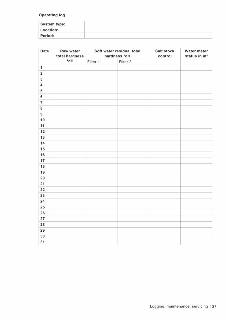
8.2 Operating log This operating log template must be copied and duplicated. The values are recorded in
accordance with the specified time interval.
Size/state daily weeklyTotal hardness (raw water) (X)Residual total hardness (soft water) (X)Operating pressure (raw water) XTemperature (raw water) XSalt reserve in the salt dissolving tank (X)Water meter status (X)
27 Logging, maintenance, servicing
System type:Location:Period:
Date Raw water total hardness
°dH
Soft water residual total hardness °dH
Salt stock control
Water meter status in m³
Filter 1 Filter 212345678910111213141516171819202122232425262728293031
Operating log
28
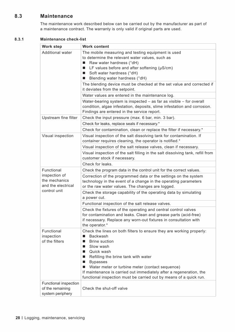
8.3 Maintenance The maintenance work described below can be carried out by the manufacturer as part of
a maintenance contract. The warranty is only valid if original parts are used.
8.3.1 Maintenance check-list
Work step Work contentAdditional water The mobile measuring and testing equipment is used
to determine the relevant water values, such as Raw water hardness (°dH)LF values before and after softening (μS/cm)Soft water hardness (°dH)Blending water hardness (°dH)The blending device must be checked at the set value and corrected if it deviates from the setpoint.Water values are entered in the maintenance log.Water-bearing system is inspected – as far as visible – for overall condition, algae infestation, deposits, slime infestation and corrosion. Findings are entered in the service report.
Upstream fine filter Check the input pressure (max. 6 bar, min. 3 bar).Check for leaks, replace seals if necessary.*Check for contamination, clean or replace the filter if necessary.*
Visual inspection Visual inspection of the salt dissolving tank for contamination. If container requires cleaning, the operator is notified.*Visual inspection of the salt release valves, clean if necessary.Visual inspection of the salt filling in the salt dissolving tank, refill from customer stock if necessary.Check for leaks.
Functional inspection of the mechanics and the electrical control unit
Check the program data in the control unit for the correct values.Correction of the programmed data or the settings on the system technology in the event of a change in the operating parameters or the raw water values. The changes are logged.Check the storage capability of the operating data by simulating a power cut.Functional inspection of the salt release valves.Check the fixtures of the operating and central control valves for contamination and leaks. Clean and grease parts (acid-free) if necessary. Replace any worn-out fixtures in consultation with the operator.*
Functional inspection of the filters
Check the lines on both filters to ensure they are working properly:BackwashBrine suctionSlow washQuick washRefilling the brine tank with waterBypassesWater meter or turbine meter (contact sequence)If maintenance is carried out immediately after a regeneration, the functional inspection must be carried out by means of a quick run.
Functional inspection of the remaining system periphery
Check the shut-off valve
Logging, maintenance, servicing

29
8.3.2 Maintenance log
After the work has been completed, the operator is informed of the maintenance result in the form of a report. In particular, this refers to deviations from the setpoint or changes that have been made in order to restore a safe operating state of the system.
8.3.3 Recommendations
To ensure optimal performance, we recommend changing the resin every 7 years.*
To ensure that the system is operated hygienically, we recommend disinfecting the resin during each decommissioning as well as each recommissioning.*
*Additional work not included in the maintenance and carried out and invoiced in consultation with the operator.
The replacement of defective parts is carried out in consultation with the operator. Spare and
wear parts will be charged for separately.
Logging, maintenance, servicing

30 Appendix
9. Appendix
9.1 Soft control head
9.2 Brine tank dimensions
Size 60 120 200 320 400Volume l 100 100 200 200 300Diameter mm 487 487 550 550 710Height H mm 665 665 1035 1035 1085
Adapter to pressure
Connecting tubes betweenpressure tanks A
Soft control head on pressure tank
CK Control
Soft water output
Raw water input

31 Appendix
9.3 Electrical connection

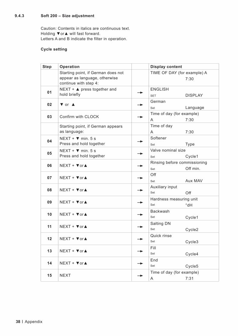
32
Step Operation Display contentStarting point, if German does not appear as language, otherwise continue with step 4:
TIME OF DAY (for example) A7:30
01NEXT + ▲ press together and hold briefly
ENGLISHSET DISPLAY
02 ▼ or ▲GermanSet Language
03 Confirm with CLOCKTime of day (for example)A 7:30
Starting point, if German appears as language:
Time of dayA 7:30
04 NEXT + ▼ min. 5 s Press and hold together
SoftenerSet Type
05 NEXT + ▼ min. 5 s Press and hold together
Valve nominal sizeSet Cycle1
06 NEXT + ▼or▲Rinsing before commissioningSet Off min.
07 NEXT + ▼or▲OffSet Aux MAV
08 NEXT + ▼or▲Auxiliary input Set Off
09 NEXT + ▼or▲Hardness measuring unitSet °dH
10 NEXT + ▼or▲BackwashSet Cycle1
11 NEXT + ▼or▲Salting DNSet Cycle2
12 NEXT + ▼or▲Quick rinseSet Cycle3
13 NEXT + ▼or▲FillSet Cycle4
14 NEXT + ▼or▲EndSet Cycle5
15 NEXTTime of day (for example)A 7:31
9.4 Soft control unit setting value9.4.1 Soft 60 – Size adjustment
Caution: Contents in italics are continuous text. Holding ▼or▲ will fast forward. Letters A and B indicate the filter in operation.
Cycle setting
Appendix
33
Step Operation Display content
01Starting point Time of day
A 7:35
02Press CLOCK briefly, hour flashes Set with▼or▲
Hour
Set8:35
03Press NEXT briefly, minute flashes Set with▼or▲
HourSet 8:40
04 NEXTTime of day (for example)A 8:40
05 NEXT + ▲ together Press down briefly
GermanSet Language
06 NEXT + ▼or▲Input hardness (measured value, for example)Set 20 °dH
07 NEXT + ▼or▲Residual hardnessSet 0 °dH
08 NEXT + ▼or▲Days between two regenerationsSet 3
09 NEXTTime of day (for example)A 8:41
Step Operation Display contentStarting point Time of day
A 8:41
10NEXT + ▼ min. 5 s Press and hold together Set with▼or▲
Softener
SetType
11 NEXT + ▼or▲Duration of backwashSet 3:00 min.
12 NEXT + ▼or▲Duration of Salting DNSet 67:00 min.
13 NEXT + ▼or▲Duration of quick rinseSet 3:00 min.
14 NEXT + ▼or▲Filling quantitySet 3.75 kg
15 NEXT + ▼or▲Softener capacitySet 54 m³ °dH
16 NEXT + ▼or▲m³ capacitySet Auto
17 NEXT + ▼or▲Immediate regenerationSet Type
Quick setting
Parameter setting
Appendix

34
Step Operation Display content
18 NEXT + ▼or▲TimeSet Relay1
19 NEXT + ▼or▲Relay1 setpointSet 0 min.
20 NEXT + ▼or▲Relay1 durationSet 73 min.
21 NEXT + ▼or▲ErrorSet Relay2
22 NEXT + ▼or▲Schedule ServiceSet Time
23 NEXT + ▼or▲Service intervalSet 1.00 a
24 NEXTService interval in accordance with schedule
1.00 a
25 NEXTTime of day (for example)A 7:30
Appendix

35
Step Operation Display contentStarting point, if German does not appear as language, otherwise continue with step 4:
TIME OF DAY (for example) A7:30
01NEXT + ▲ press together and hold briefly
ENGLISHSET DISPLAY
02 ▼ or ▲GermanSet Language
03 Confirm with CLOCKTime of day (for example)A 7:30
Starting point, if German appears as language:
Time of dayA 7:30
04 NEXT + ▼ min. 5 s Press and hold together
SoftenerSet Type
05 NEXT + ▼ min. 5 s Press and hold together
Valve nominal sizeSet 1.0T
06 NEXT + ▼or▲Rinsing before commissioningSet Off min.
07 NEXT + ▼or▲OffSet Aux MAV
08 NEXT + ▼or▲Auxiliary inputSet Off
09 NEXT + ▼or▲Hardness measuring unitSet °dH
10 NEXT + ▼or▲BackwashSet Cycle1
11 NEXT + ▼or▲Salting DNSet Cycle2
12 NEXT + ▼or▲Quick rinseSet Cycle3
13 NEXT + ▼or▲FillSet Cycle4
14 NEXT + ▼or▲EndSet Cycle5
15 NEXTTime of day (for example)A 7:31
9.4.2 Soft 120 – Size adjustment
Caution: Contents in italics are continuous text. Holding ▼or▲ will fast forward. Letters A and B indicate the filter in operation.
Cycle setting
Appendix

36
Step Operation Display content
01Starting point Time of day
A 7:35
02Press CLOCK briefly, hour flashes Set with▼or▲
Hour
Set8:35
03Press NEXT briefly, minute flashes Set with▼or▲
HourSet 8:40
04 NEXTTime of day (for example)A 8:40
05 NEXT + ▲ together Press down briefly
GermanSet Language
06 NEXT + ▼or▲Input hardness (measured value, for example)Set 20 °dH
07 NEXT + ▼or▲Residual hardnessSet 0 °dH
08 NEXT + ▼or▲Days between two regenerationsSet 3
09 NEXTTime of day (for example)A 8:41
Step Operation Display contentStarting point Time of day
A 8:41
10NEXT + ▼ min. 5 s Press and hold together Set with▼or▲
Softener
SetType
11 NEXT + ▼or▲Duration of backwashSet 3:00 min.
12 NEXT + ▼or▲Duration of Salting DN Set 70:00 min.
13 NEXT + ▼or▲Duration of quick rinse Set 3:00 min.
14 NEXT + ▼or▲Filling quantitySet 7.50 kg
15 NEXT + ▼or▲Softener capacitySet 105 m³ °dH
16 NEXT + ▼or▲m³ capacitySet Auto
17 NEXT + ▼or▲Immediate regenerationSet Type
Quick setting
Parameter setting
Appendix

37
Step Operation Display content
18 NEXT + ▼or▲TimeSet Relay1
19 NEXT + ▼or▲Relay1 setpointSet 0 min.
20 NEXT + ▼or▲Relay1 durationSet 76 min.
21 NEXT + ▼or▲ErrorSet Relay2
22 NEXT + ▼or▲Schedule ServiceSet Time
23 NEXT + ▼or▲Service intervalSet 1.00 a
24 NEXTService interval in accordance with schedule
1.00 a
25 NEXTTime of day (for example)A 7:30
Appendix
38
Step Operation Display contentStarting point, if German does not appear as language, otherwise continue with step 4:
TIME OF DAY (for example) A7:30
01NEXT + ▲ press together and hold briefly
ENGLISHSET DISPLAY
02 ▼ or ▲GermanSet Language
03 Confirm with CLOCKTime of day (for example)A 7:30
Starting point, if German appears as language:
Time of dayA 7:30
04 NEXT + ▼ min. 5 s Press and hold together
SoftenerSet Type
05 NEXT + ▼ min. 5 s Press and hold together
Valve nominal sizeSet Cycle1
06 NEXT + ▼or▲Rinsing before commissioningSet Off min.
07 NEXT + ▼or▲OffSet Aux MAV
08 NEXT + ▼or▲Auxiliary inputSet Off
09 NEXT + ▼or▲Hardness measuring unitSet °dH
10 NEXT + ▼or▲BackwashSet Cycle1
11 NEXT + ▼or▲Salting DNSet Cycle2
12 NEXT + ▼or▲Quick rinseSet Cycle3
13 NEXT + ▼or▲FillSet Cycle4
14 NEXT + ▼or▲EndSet Cycle5
15 NEXTTime of day (for example)A 7:31
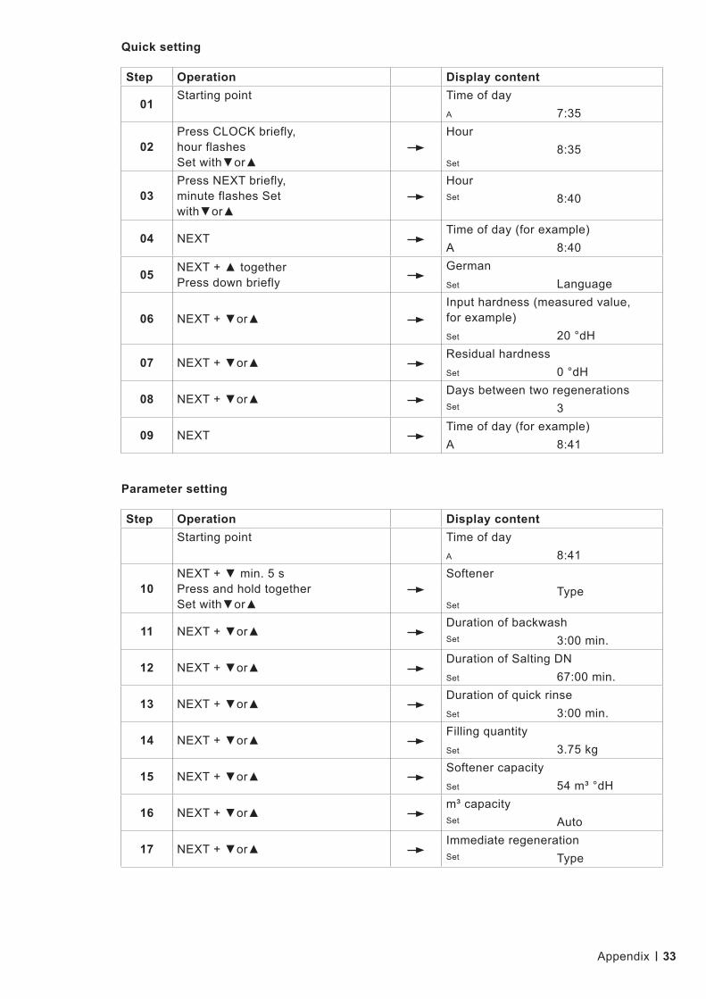
9.4.3 Soft 200 – Size adjustment
Caution: Contents in italics are continuous text. Holding ▼or▲ will fast forward. Letters A and B indicate the filter in operation.
Cycle setting
Appendix

39
Step Operation Display content
01Starting point Time of day
A 7:35
02Press CLOCK briefly, hour flashes Set with▼or▲
Hour
Set8:35
03Press NEXT briefly, minute flashes Set with▼or▲
HourSet 8:40
04 NEXTTime of day (for example)A 8:40
05 NEXT + ▲ together Press down briefly
GermanSet Language
06 NEXT + ▼or▲Input hardness (measured value, for example)Set 20 °dH
07 NEXT + ▼or▲Residual hardnessSet 0 °dH
08 NEXT + ▼or▲Days between two regenerationsSet 3
09 NEXTTime of day (for example)A 8:41
Step Operation Display contentStarting point Time of day
A 8:41
10NEXT + ▼ min. 5 s Press and hold together Set with▼or▲
Softener
SetType
11 NEXT + ▼or▲Duration of backwashSet 5:00 min.
12 NEXT + ▼or▲Duration of Salting DNSet 115:00 min.
13 NEXT + ▼or▲Duration of quick rinseSet 5:00 min.
14 NEXT + ▼or▲Filling quantitySet 12.50 kg
15 NEXT + ▼or▲Softener capacitySet 180 m³ °dH
16 NEXT + ▼or▲m³ capacitySet Auto
17 NEXT + ▼or▲Immediate regenerationSet Type
Quick setting
Parameter setting
Appendix

40
Step Operation Display content
18 NEXT + ▼or▲TimeSet Relay1
19 NEXT + ▼or▲Relay1 setpointSet 0 min.
20 NEXT + ▼or▲Relay1 durationSet 125 min.
21 NEXT + ▼or▲ErrorSet Relay2
22 NEXT + ▼or▲Schedule ServiceSet Time
23 NEXT + ▼or▲Service intervalSet 1.00 a
24 NEXTService interval in accordance with schedule
1.00 a
25 NEXTTime of day (for example)A 7:30
Appendix

41
Step Operation Display contentStarting point, if German does not appear as language, otherwise continue with step 4:
TIME OF DAY (for example) A7:30
01NEXT + ▲ press together and hold briefly
ENGLISHSET DISPLAY
02 ▼ or ▲GermanSet Language
03 Confirm with CLOCKTime of day (for example)A 7:30
Starting point, if German appears as language:
Time of dayA 7:30
04 NEXT + ▼ min. 5 s Press and hold together
SoftenerSet Type
05 NEXT + ▼ min. 5 s Press and hold together
Valve nominal sizeSet 1.0T
06 NEXT + ▼or▲Rinsing before commissioningSet Off min.
07 NEXT + ▼or▲OffSet Aux MAV
08 NEXT + ▼or▲Auxiliary inputSet Off
09 NEXT + ▼or▲Hardness measuring unitSet °dH
10 NEXT + ▼or▲BackwashSet Cycle1
11 NEXT + ▼or▲Salting DNSet Cycle2
12 NEXT + ▼or▲Quick rinseSet Cycle3
13 NEXT + ▼or▲FillSet Cycle4
14 NEXT + ▼or▲EndSet Cycle5
15 NEXTTime of day (for example)A 7:31
9.4.4 Soft 320 – Size adjustment
Caution: Contents in italics are continuous text. Holding ▼or▲ will fast forward. Letters A and B indicate the filter in operation.
Cycle setting
Appendix

42
Step Operation Display content
01Starting point Time of day
A 7:35
02Press CLOCK briefly, hour flashes Set with▼or▲
Hour
Set8:35
03Press NEXT briefly, minute flashes Set with▼or▲
HourSet 8:40
04 NEXTTime of day (for example)A 8:40
05 NEXT + ▲ together Press down briefly
GermanSet Language
06 NEXT + ▼or▲Input hardness (measured value, for example)Set 20 °dH
07 NEXT + ▼or▲Residual hardnessSet 0 °dH
08 NEXT + ▼or▲Days between two regenerationsSet 3
09 NEXTTime of day (for example)A 8:41
Step Operation Display contentStarting point Time of day
A 8:41
10NEXT + ▼ min. 5 s Press and hold together Set with▼or▲
Softener
SetType
11 NEXT + ▼or▲Duration of backwashSet 7:00 min.
12 NEXT + ▼or▲Duration of Salting DNSet 102:00 min.
13 NEXT + ▼or▲Duration of quick rinseSet 7:00 min.
14 NEXT + ▼or▲Filling quantitySet 20.00 kg
15 NEXT + ▼or▲Softener capacitySet 290 m³ °dH
16 NEXT + ▼or▲m³ capacitySet Auto
17 NEXT + ▼or▲Immediate regenerationSet Type
Quick setting
Parameter setting
Appendix

43
Step Operation Display content
18 NEXT + ▼or▲TimeSet Relay1
19 NEXT + ▼or▲Relay1 setpointSet 0 min.
20 NEXT + ▼or▲Relay1 durationSet 116 min.
21 NEXT + ▼or▲ErrorSet Relay2
22 NEXT + ▼or▲Schedule ServiceSet Time
23 NEXT + ▼or▲Service intervalSet 1.00 a
24 NEXTService interval in accordance with schedule
1.00 a
25 NEXTTime of day (for example)A 7:30
Appendix

44
Step Operation Display contentStarting point, if German does not appear as language, otherwise continue with step 4:
TIME OF DAY (for example) A7:30
01NEXT + ▲ press together and hold briefly
ENGLISHSET DISPLAY
02 ▼ or ▲GermanSet Language
03 Confirm with CLOCKTime of day (for example)A 7:30
Starting point, if German appears as language:
Time of dayA 7:30
04 NEXT + ▼ min. 5 s Press and hold together
SoftenerSet Type
05 NEXT + ▼ min. 5 s Press and hold together
Valve nominal sizeSet Cycle1
06 NEXT + ▼or▲Rinsing before commissioningSet Off min.
07 NEXT + ▼or▲OffSet Aux MAV
08 NEXT + ▼or▲Auxiliary inputSet Off
09 NEXT + ▼or▲Hardness measuring unitSet °dH
10 NEXT + ▼or▲BackwashSet Cycle1
11 NEXT + ▼or▲Salting DNSet Cycle2
12 NEXT + ▼or▲Quick rinseSet Cycle3
13 NEXT + ▼or▲FillSet Cycle4
14 NEXT + ▼or▲EndSet Cycle5
15 NEXTTime of day (for example)A 7:31
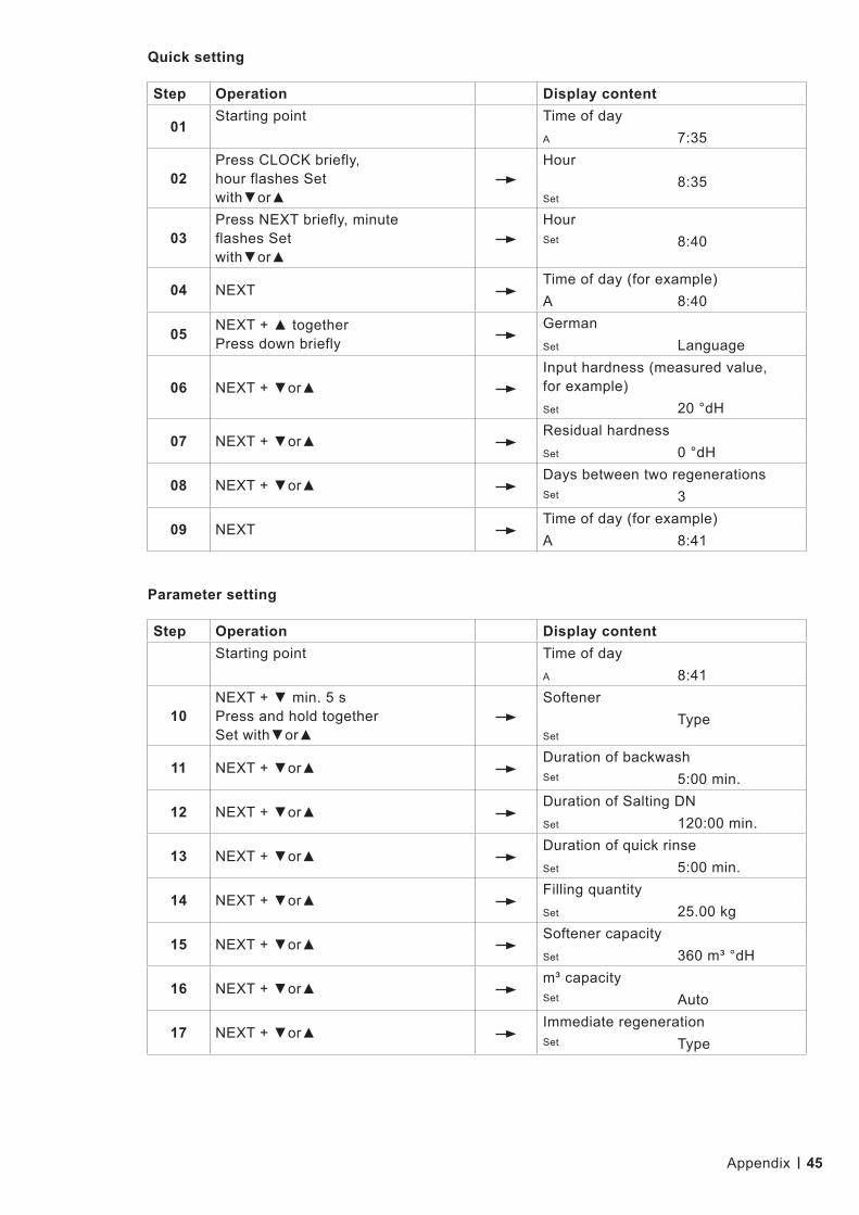
9.4.5 Soft 400 – Size adjustment
Caution: Contents in italics are continuous text. Holding ▼or▲ will fast forward. Letters A and B indicate the filter in operation.
Cycle setting
Appendix
45
Step Operation Display content
01Starting point Time of day
A 7:35
02Press CLOCK briefly, hour flashes Set with▼or▲
Hour
Set8:35
03Press NEXT briefly, minute flashes Set with▼or▲
HourSet 8:40
04 NEXTTime of day (for example)A 8:40
05 NEXT + ▲ together Press down briefly
GermanSet Language
06 NEXT + ▼or▲Input hardness (measured value, for example)Set 20 °dH
07 NEXT + ▼or▲Residual hardnessSet 0 °dH
08 NEXT + ▼or▲Days between two regenerationsSet 3
09 NEXTTime of day (for example)A 8:41
Step Operation Display contentStarting point Time of day
A 8:41
10NEXT + ▼ min. 5 s Press and hold together Set with▼or▲
Softener
SetType
11 NEXT + ▼or▲Duration of backwashSet 5:00 min.
12 NEXT + ▼or▲Duration of Salting DN Set 120:00 min.
13 NEXT + ▼or▲Duration of quick rinseSet 5:00 min.
14 NEXT + ▼or▲Filling quantitySet 25.00 kg
15 NEXT + ▼or▲Softener capacitySet 360 m³ °dH
16 NEXT + ▼or▲m³ capacitySet Auto
17 NEXT + ▼or▲Immediate regenerationSet Type
Parameter setting
Quick setting
Appendix

46
Step Operation Display content
18 NEXT + ▼or▲TimeSet Relay1
19 NEXT + ▼or▲Relay1 setpointSet 0 min.
20 NEXT + ▼or▲Relay1 durationSet 130 min.
21 NEXT + ▼or▲ErrorSet Relay2
22 NEXT + ▼or▲Schedule ServiceSet Time
23 NEXT + ▼or▲Service intervalSet 1.00 a
24 NEXTService interval in accordance with schedule
1.00 a
25 NEXTTime of day (for example)A 7:30
Appendix
47
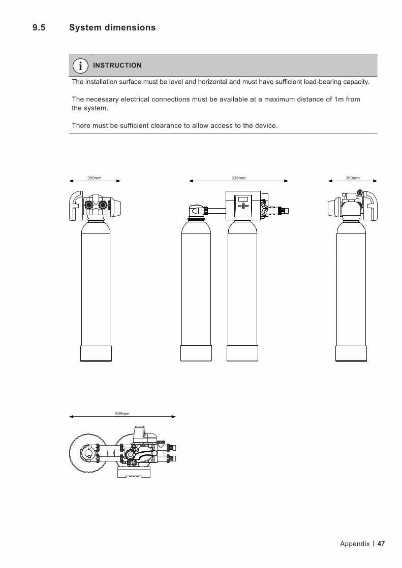
9.5 System dimensions
INSTRUCTION
The installation surface must be level and horizontal and must have sufficient load-bearing capacity.
The necessary electrical connections must be available at a maximum distance of 1m from the system.
There must be sufficient clearance to allow access to the device.
350mm 635mm
635mm
350mm
Appendix
48
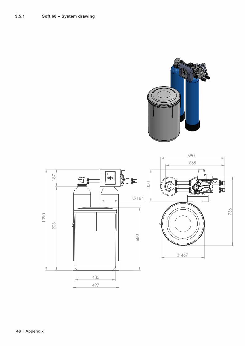
9.5.1 Soft 60 – System drawing
Appendix

49
9.5.2 Soft 120 – System drawing
Appendix

50
9.5.3 Soft 200 – System drawing
Appendix
51
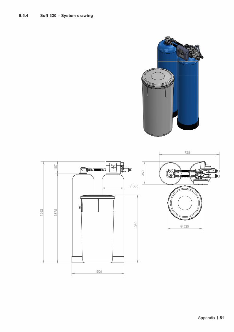
9.5.4 Soft 320 – System drawing
Appendix

52
9.5.5 Soft 400 – System drawing
Appendix
53
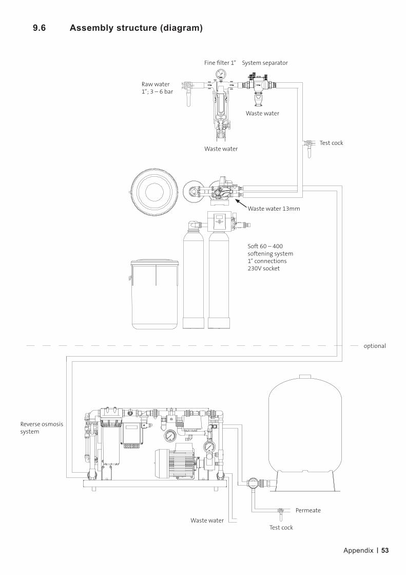
9.6 Assembly structure (diagram)
Raw water1“; 3 – 6 bar
Fine filter 1“
Waste waterTest cock
Waste water 13mm
optional
Waste water
Permeate
Test cock
Soft 60 – 400 softening system1“ connections 230V socket
Reverse osmosis system
Waste water
System separator
Appendix
54
Notes

55
Notes

© 07/2021 Condair GmbH. Subject to errors and technical modifications without notice. The content is correct at the time of going to press.If you have any questions about the documentation, please contact the head office in Germany.
Condair GmbH Parkring 3, 85748 Garching Tel. +49 (0) 89 20 70 08-0, Fax +49 (0) 89 20 70 08-140, www.condair.de
Condair GmbH Regionalcenter SüdParkring 3D-85748 GarchingTel. +49 (0) 89 / 20 70 08-0Fax +49 (0) 89 / 20 70 08-140
Regionalcenter SüdwestZettachring 6D-70567 StuttgartTel. +49 (0) 711 / 25 29 70-0Fax +49 (0) 711 / 25 29 70-40
Regionalcenter MitteNordendstraße 2D-64546 Mörfelden-WalldorfTel. +49 (0) 61 05 / 963 88-0Fax +49 (0) 61 05 / 963 88-40
Regionalcenter WestWerftstraße 25D-40549 DüsseldorfTel. +49 (0) 211 / 54 20 35-0Fax +49 (0) 211 / 54 20 35-60
Regionalcenter NordLüneburger Straße 4D-30880 Laatzen - RethenTel. +49 (0) 511 / 51 54 13 11Fax +49 (0) 511 / 51 54 13 40
Regionalcenter OstChausseestraße 88D-10115 BerlinTel. +49 (0) 30 / 921 03 44 -0Fax +49 (0) 30 / 921 03 44-40
Condair AustriaPerfektastraße 45A-1230 WienTel. +43 (0) 1 / 60 33 111-0Fax +43 (0) 1 / 60 33 111 399
Related Documents