(19) United States US 200701 49496A1 (2) Patent Application Publication (10) Pub. No.: US 2007/0149496 A1 Tuszynski et al. (43) Pub. Date: Jun. 28, 2007 (54) (76) (21) (22) (63) WATER-SOLUBLE COMPOUND Inventors: Jack Tuszynski, Edmonton (CA); Howard J. Greenwald, Rochester, NY (US); Stephen H. Curry, Rochester, NY (US); Kendrick Goss, Brighton, MA (US) Correspondence Address: Michael L. Weiner Technology Innovations Suite 215 150 Lucius Godon Drive West Henrietta, NY 14586 (US) Appl. No.: 10/923,615 Filed: Aug. 20, 2004 Related U.S. Application Data Continuation-in-part of application No. 10/878,905, filed on Jun. 28, 2004. Continuation-in-part of application No. 10/808,618, filed on Mar. 24, 2004. Continuation-in-part of application No. 10/867,517, filed on Jun. 14, 2004. (60) Provisional application No. 60/516,134, filed on Oct. 31, 2003. Publication Classification (51) Int. Cl. A61R 3 I/555 (2006.01) C07F 15/02 (2006.01) (52) U.S. Cl. ............................................ 514/184; 549/206 (57) ABSTRACT A water-soluble magnetic anti-mitotic compound with a water-solubility of at least 100 micrograms per milliliter, a molecular weight of at least 150 grams per mole, a mitotic index factor of at least 10 percent, a positive magnetic susceptibility of at least 1,000×107° cps, and a magnetic moment of at least 0.5 bohr magnetrons, wherein said compound is comprised of at least 7 carbon atoms and at least one inorganic atom with a positive magnetic suscep tibility of at least 200×107° cps.

Welcome message from author
This document is posted to help you gain knowledge. Please leave a comment to let me know what you think about it! Share it to your friends and learn new things together.
Transcript
(19) United States US 200701 49496A1
(2) Patent Application Publication (10) Pub. No.: US 2007/0149496 A1 Tuszynski et al. (43) Pub. Date: Jun. 28, 2007
(54)
(76)
(21)
(22)
(63)
WATER-SOLUBLE COMPOUND
Inventors: Jack Tuszynski, Edmonton (CA); Howard J. Greenwald, Rochester, NY (US); Stephen H. Curry, Rochester, NY (US); Kendrick Goss, Brighton, MA (US)
Correspondence Address: Michael L. Weiner Technology Innovations Suite 215 150 Lucius Godon Drive West Henrietta, NY 14586 (US)
Appl. No.: 10/923,615
Filed: Aug. 20, 2004
Related U.S. Application Data
Continuation-in-part of application No. 10/878,905, filed on Jun. 28, 2004. Continuation-in-part of application No. 10/808,618, filed on Mar. 24, 2004.
Continuation-in-part of application No. 10/867,517, filed on Jun. 14, 2004.
(60) Provisional application No. 60/516,134, filed on Oct. 31, 2003.
Publication Classification
(51) Int. Cl. A61R 3 I/555 (2006.01) C07F 15/02 (2006.01)
(52) U.S. Cl. ............................................ 514/184; 549/206
(57) ABSTRACT
A water-soluble magnetic anti-mitotic compound with a water-solubility of at least 100 micrograms per milliliter, a molecular weight of at least 150 grams per mole, a mitotic index factor of at least 10 percent, a positive magnetic susceptibility of at least 1,000×107° cps, and a magnetic moment of at least 0.5 bohr magnetrons, wherein said compound is comprised of at least 7 carbon atoms and at least one inorganic atom with a positive magnetic suscep tibility of at least 200×107° cps.

US 2007/014949.6 A1
ZZZZZZZZZZZZZZZZZZZ8Z92 91 º ':','<- #10£
??ETTO HINODZE
ZI9
Patent Application Publication Jun. 28, 2007 Sheet 1 of 5

"> INTE F??-OE??L?, EI EEE?????EI }-|–ÈÝ):
US 2007/014949.6 A1 Patent Application Publication Jun. 28, 2007 Sheet 2 of 5

US 2007/0149496 A1 Patent Application Publication Jun. 28, 2007 Sheet 3 of 5
TEICJOW Å5)OTOWOH ABICJOW
5)[\\]O] ELLWC|ICINWO HO WON HIOIHHE SONICINIOE LOICIERJod
SOIOV OWIN\/ AEX AHLLNBC]I
NIELLO\ld IE15)\]\/]L HO ERITULOTNIS NIV/180

US 2007/0149496 A1 Patent Application Publication Jun. 28, 2007 Sheet 4 of 5
CINTOSWYLITT) ATSTOEINVITIT WIS SOTTHCl \|E|1SINIWCIV/ ELL\/C/IC]NWO ANV/W NAOH EINIWRIELLEICH
v'EIA ZEZ
OZZ
982
WIWRIEHL (EdAH ATTWLLNB mÕES Sºn HQ SNIELLO\ld ZZZ


US 2007/014949.6 A1
WATER-SOLUBLE COMPOUND
CROSS-REFERENCE TO RELATED PATENT APPLICATIONS
[0001] This application claims priority from United States provisional patent application U.S. Ser. No. 60/516,134, filed on Oct. 31, 2003, the entire disclosure of which is hereby incorporated by reference into this specification. [0002] This application is a continuation-in-part of appli cants’ U.S. patent application Ser. No. 10/808,618 (filed on Mar. 24, 2004), of applicants’ U.S. patent application Ser. No. 10/867,517 (filed on Jun. 14, 2004), and of applicants’ U.S. patent application Ser. No. 10/878,905 (filed on Jun. 28, 2004).
INCORPORATION BY REFERENCE OF MATERIAL SUBMITTED ON A COMPACT
DISC
[0003] Reference is hereby made to a Sequence Listing, a Table, and/or a Computer Program Listing appendix that was submitted on compact disc. This compact disc contains one file entitlede “sequence list.ST25” created on Feb. 11, 2005. The file size on the disk is 47,104 bytes. The entire content of this compact disc is hereby incorporated by reference into this specification.
FIELD OF THE INVENTION
[0004] A water-soluble magnetic anti-mitotic compound with a water-solubility of at least 1100 micrograms per milliliter, a molecular weight of at least 150 grams per mole, a mitotic index factor of at least 10 percent, a positive magnetic susceptibility of at least 1,000×107° cys, and a magnetic moment of at least 0.5 bohr magnetrons, wherein said compound is comprised of at least 7 carbon atoms and at least one inorganic atom with a positive magnetic sus ceptibility of at least 200×107° cps.
BACKGROUND OF THE INVENTION
[0005] Paclitaxel is a complex diterpenoid that is widely used as an anti-mitotic agent; it consists of a bulky, fused ring system and an extended side chain that is required for its activity. See, e.g., page 112 of Gunda I. Georg’s “Taxane Anticancer Agents: Basic Science and Current Status,” ACS Symposium Series 583 (American Chemical Society, Wash ington, D.C., 1995). [0006] The aqueous solubility of paclitaxel is relatively low. Thus, as is disclosed at page 112 of such Georg text, estimates of paclitaxel solubility vary widely, ranging from about 30 micrograms per milliliter and about 7 micrograms per milliliter to less than 0.7 micrograms per milliliter. [0007] The molecular weight of paclitaxel is in excess of 700; this relatively high molecular weight is one factor that, according to the well-known “rule of 5,” contributes to paclitaxel’s poor water solubility. [0008] The “rule of 5” was set forth by Christopher A. Lipinski et al. in an article entitled “Experimental and computational approaches to estimate solubility and perme ability in drug discovery and development settings,” Adv. Drug Delivery Rev., 1997, 23(1-3), 3-25. In this article, it was disclosed that: “In the USAN set we found that the sum of Ns and Os in the molecular formula was greater than 10
Jun. 28, 2007
in 12% of the compounds. Eleven percent of compounds had a MWT of over 500 . . . . The ‘rule of 5 states that: poor absorption of permeation is more likely where: A. There are more than 5H-bond donors (expressed as the sum of OHs and NHs); B. The MWT is over 500; C. The LogP is over 500 . . . ; D. There are more than 10H-bond acceptors (expressed as the sum of Ns and Os).”
[0009] The Lipinksi “rule of 5” has also erroneously been referred to as the “Pfizer rule of 5,” as is illustrated by U.S. Pat. No. 6,675,136, the entire disclosure of which is hereby incorporated by reference into this specification. As is dis closed in such patent, “To further illustrate the versatility of the present technique, we also introduce the concept of ‘anchor’ objects. Anchor objects are molecules situated at the corners of a region of the drug space that is defined by Pfizer’s ‘rule of 5°. This rule has been empirically derived by a computer analysis of known drugs, as described by Chris topher A. Pfizer and co-workers in Adv. Drug Delivery Rev., vol. 23, pp. 3-25 (1997). The ‘rule of 5’ is focused on drug permeability and oral absorption. . . . According to Pfizer’s “rule of 5”, LIPO and HBDON are between 0 and 5, HBACC is between 0 and 10, and M.W. has a maximum of 500.”
[0010] The problems that high molecular weight com pounds have with poor water solubility are discussed in U.S. Pat. No. 6,667,048 of Karel J. Lambert et al., which dis closes an “emulsion vehicle for a poorly soluble drug.” In the “background of the invention” section of this patent, it is disclosed that: “Hundreds of medically useful compounds are discovered every year, but clinical use of these drugs is possible only if a drug delivery vehicle is developed to transport them to their therapeutic target in the human body. This problem is particularly critical for drugs requiring intravenous injection in order to reach their therapeutic target or dosage but which are water insoluble or poorly water insoluble. For such hydrophobic compounds, direct injection may be impossible or highly dangerous, and can result in hemolysis, phlebitis, hypersensitivity, organ failure and/or death. Such compounds are termed by pharmacists ‘lipophilic,’ ‘hydrophobic,” or in their most difficult form, ‘aamphiphobic . . . . A few examples of therapeutic sub stances in these categories are ibuprofen, diazepam, grise fulvin, cyclosporin, cortisone, proleukin, cortisone, proleu kin, etoposide and paclitaxel. . . . .”
[0011] As is also disclosed in U.S. Pat. No. 6,667,048, “Administration of chemotherapuetic or anti-cancer agents is particularly problematic. Low solubility anti-cancer agents are difficult to solubilize and supply at therapeutically useful levels. On the other hand, water-soluble anti-cancer agents are generally taken up by both cancer and non-cancer cells thereby exhibiting non-specificity. . . . Efforts to improve water-solubility and comfort of administration of such agents have not solved, and may have worsened, the two fundamental problems of cancer chemotherapy: 1) non-specific toxicity, and 2) rapid clearance from the blood stream by non-specific mechanisms. In the case of cytotox ins, which form the majority of currently available chemo therapies, these two problems are clearly related. Whenever the therapeutic is taken up by noncancerous cells, a dimin ished amount of the drug remains available to treat the cancer, and more importantly, the normal cell ingesting the drug is killed.”

US 2007/014949.6 A1
[0012] As is also disclosed in U.S. Pat. No. 6,667,048, “The chemotherapeutic must be present throughout the affected tissue(s) at high concentration for a sustained period of time so that it may be taken up by the cancer cells, but not at so high a concentration that normal cells are injured beyond repair. Obviously, water-soluble molecules can be administered in this way, but only by slow, continuous infusion and monitoring, aspects which entail great diffi culty, expense and inconvenience.” [0013] It does not appear that the prior art has provided a water-soluble anti-mitotic agent that is capable of solving the problems discussed in U.S. Pat. No. 6,667,048. It is an object of this invention to provide such an agent. In par ticular, and in one embodiment, it is an object of this invention to provide a magnetic anti-mitotic composition that can be directed to be more toxic to cancer cells than normal cells. Furthermore, and in another embodiment, it is another object of this invention to provide a delivery system that will provide a chemotherapeutic agent at a high con centration for a sustained period of time but not at such a high concentration that a substantial number of normal cells are injured beyond repair.
SUMMARY OF THE INVENTION
[0014] In accordance with one embodiment of this inven tion, there is provided a water-soluble magnetic anti-mitotic compound with a water-solubility of at least 100 micro grams per milliliter, a molecular weight of at least 150 grams per mole, a mitotic index factor of at least 10 percent, a positive magnetic susceptibility of at least 1,000×107° cgs, and a magnetic moment of at least 0.5 bohr magnetrons, wherein said compound is comprised of at least 7 carbon atoms and at least one inorganic atom with a positive magnetic susceptibility of at least 200×107° cps. [0015] In accordance with yet another embodiment of this invention, there is provided a compound with molecular weight of at least about 550, a water solubility of at least about 10 micrograms per milliliter, a pKa dissociation constant of from about 1 to about 15, and a partition coefficient of from about 1.0 to about 50.
BRIEF DESCRIPTION OF THE DRAWINGS
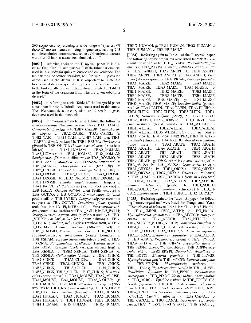
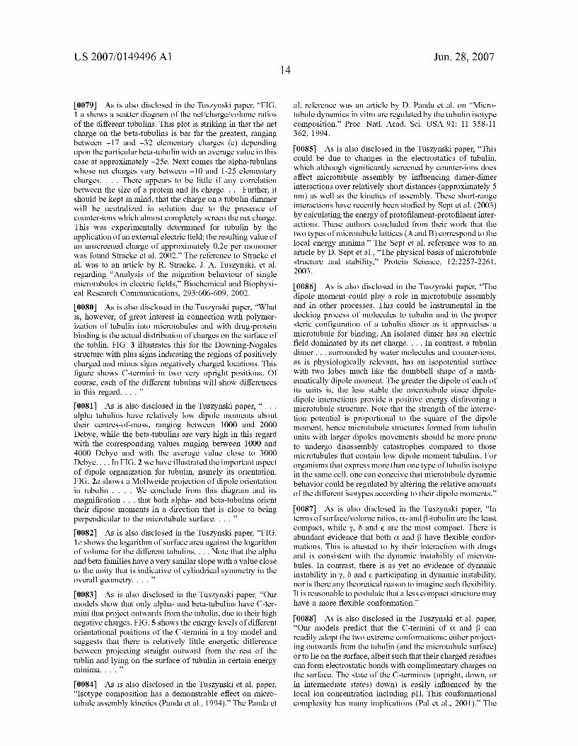
[0016] The invention will be described with reference to the specification and the enclosed drawings, in which like numerals refer to like elements, and wherein: [0017] FIG. 1 is a schematic illustration of one preferred implantable assembly of the invention; [0018] FIG. 2 is a schematic illustration of a flow meter that may be used in conjunction with the implantable assembly of claim 1: [0019] FIG. 3 is a flow diagram of one preferred process of the invention; [0020] FIG. 4 is a flow diagram of another preferred process of the invention; and [0021] FIG. 5 is a flow diagram of yet another preferred process of the invention.
DESCRIPTION OF THE PREFERRED EMBODIMENTS
[0022] The magnetic anti-mitotic compound of this inven tion is particularly well-adapted to bind either to tubulin
Jun. 28, 2007
isotypes and/or microtubules comprised of such isotypes and/or various proteins that are involved in microtubule dynamics. In the first part of this specification, applicants will discuss the preparation of a database of tubulin isotopes. In the second part of this specification, applicants will discuss certain preferred, magnetic compounds that, in one embodiment, target such tubulin isotypes and/or the micro tubules they make up. A Process for Preparing a Tubulin Isotype Database [0023] Tubulin is a component of microtubules. At the molecular level tubulin’s roles are highly complex. For example, microtubules undergo cycles of rapid growth and disassembly in a process known as “dynamic instability” that appears to be critical for microtubule function. In one embodiment, the magnetic anti-mitotic compounds of this invention are capable of disrupting and/or modifying such process of “dynamic instability,” either by interacting with one or more tubulin isotypes, and/or one or more proteins involved in the dynamics of microtubule assembly and/or disassembly, and/or the microtubules themselves. [0024] Both the alpha and the beta forms of tubulin consist of a series of isotypes, differing in amino acid sequence, each one encoded by a different gene. See, e.g., an article by Richard F. Luduena on “The multiple forms of tublin: different gene products and covalent modifications,” Int. Rev. Cytol. 178-107-275 (1998). Reference also may be had, e.g., to U.S. Pat. No. 6,306,615 (detection method for monitoring beta-tubulin isotype specific modification); the entire disclosure of this United States patent is hereby incorporated by reference into this specification. [0025] An interesting discussion of tubulin isotypes is also presented in published United States patent application 2004/0121351, the entire disclosure of which is hereby incorporated by reference into this specification. As is dis closed in this published patent application, “Microtubules are essential to the eucaryotic cell due as they are involved in many processes and functions such as, e.g., being com ponents of the cytoskeleton, of the centrioles and ciliums and in the formation of spindle fibres during mitosis. The constituents of microtubules are heterodimers consisting of one O-tubulin molecule and one fl-tubulin molecule. These two related self-associating 50 kDa proteins are encoded by a multigen family. The various members of this multigen family are dispersed all over the human genome. Both Cº-tubulin and 5-tubulin are most likely to originate from a common ancestor as their amino acid sequence shows a homology of up to 50%. In man there are at least 15 genes or pseudogenes for 5-tubulin.” [0026] As is also disclosed in published United States patent application 2004/0121351, “The conservation of structure and regulatory functions among the fl-tubulin genes in three vertebrate species (chicken, mouse and human) allowed the identification of and categorization into six major classes of beta-tubulin polypeptide isotypes on the basis of their variable carboxyterminal ends. The specific, highly variable 15 carboxyterminal amino acids are very conserved among the various species. Beta-tubulins of cat egories I, II, and IV are closely related differing only 2-4% in contrast to categories III, V and VI which differ in 8-16% of amino acid positions [Sullivan K. F., 1988, Ann. Rev. Cell Biol. 4: 687-716] . . . the expression pattern is very similar between the various species as can be taken from the

US 2007/014949.6 A1
following table [Sullivan K. F., 1988, Ann. Rev. Cell Biol. 4: 687-716] which comprises the respective human members of each class: 1 isotype member expression pattern class 1 HM 40 ubiquitous class II H 59 mostly in the brain class III H 54 exclusively in the brain class IVa H 55 exclusively in the brain class IVb H 52 ubiquitous. . . . “The C terminal end of the beta-tubulins starting from amino acid 430 is regarded as highly variable between the various classes. Additionally, the members of the same class seem to be very conserved between the various species. As tubulin molecules are involved in many processes and form part of many struc tures in the eucaryotic cell, they are possible targets for pharmaceutically active compounds. As tubulin is more particularly the main structural component of the microtu bules it may act as point of attack for anticancer drugs such as vinblastin, colchicin, estramustin and taxol which inter fere with microtubule function. The mode of action is such that cytostatic agents such as the ones mentioned above, bind to the carboxyterminal end the fl-tubulin which upon such binding undergoes a conformational change. For example, Kavallaris et al. [Kavallaris et al. 1997, J. Clin. Invest. 100: 1282-1293] reported a change in the expression of specific fl-tubulin isotypes (class I, II, III, and IVa) in taxol resistant epithelial ovarian tumor. It was concluded that these tubulins are involved in the formation of the taxol resistance. Also a high expression of class III fl-tubulins was found in some forms of lung cancer suggesting that this isotype may be used as a diagnostic marker.”
[0027] The function of certain tubulins in Taxol resistance was also discussed in U.S. Pat. No. 6,362,321, the entire disclosure of which is hereby incorporated by reference into this specification. As is disclosed in this patent, “Taxol is a natural product derived from the bark of Taxus brevafolio (Pacific yew). Taxol inhibits microtubule depolymerization during mitosis and results in subsequent cell death. Taxol displays a broad spectrum of tumoricidal activity including against breast, ovary and lung cancer (McGuire et al., 1996, N. Engld. J. Med. 334:1-6; and Johnson et al., 1996, J. Clin. Ocol. 14:2054-2060). While taxol is often effective in treat ment of these malignancies, it is usually not curative because of eventual development of taxol resistance. Cellular resis tance to taxol may include mechanisms such as enhanced expression of P-glycoprotein and alterations in tubulin struc ture through gene mutations in the ? chain or changes in the ratio of tubulin isomers within the polymerized microtubule (Wahl et al., 1996, Nature Medicine 2:72-79; Horwitz et al., 1993, Natl. Cancer Inst. 15:55-61; Haber et al., 1995, J. Biol. Chem. 270:31269-31275; and Giannakakou et al., 1997, J. Biol. Chem. 272:17.118-17125). . . .” In one embodiment of this invention, the magnetetic anti-mitotic compound of this invention is used in conjunction with paclitaxel to provide an improved anti-cancer composition. Without wishing to be bound to any particular theory, applicants believe that their anti-mitotic compound targets a tubulin isotype that is responsible for the drug resistance to paclitaxel.
[0028] The increased presence of certain tubulin isotypes associated with certain types of cancers was noted in an article by Tien Yeh et al., “The Bri Isotype of Tubulin is Present in the Cell Nuclei of a Variety of Cancers,” Cell Motility and the Cytoskeleton 57:96-106 (2004). Constructs of these Bn isotypes and applicants’ magnetic anti-mitotic compound comprise one embodiment of the present inven tion.
Jun. 28, 2007
[0029] The Yeh et al. article discloses that both alpha tubulin and beta-tubulin consist of a series of isotypes differing in amino acid sequence, each one encoded by a different gene; and it refers to a 1998 article by Richard F. Luduena entitled “The multiple forms of tubulin: different gene products and covalent modifications,” Int. Rev. Cytol 178:207-275. The Yeh et al. article also disclosed that the Bn isotype of tubulin is present in the nuclei of many tumors, stating that “Three quarters (75%) of the tumors we exam ined contained nuclear the Bn (Table I).” The authors of the Yeh et al. article suggest that (at page 104) “ . . . it would be interesting to explore the possibility of using nuclear Bn as a chemotherapeutic target.”
[0030] It thus appears that many isotypes of tubulin might be “chemotherapeutic targets” such as, e.g., the “nuclear Br’ disclosed in the Yeh et al. article, or the “ . . . specific fl-tubulin isotypes (class I, II, III, and IVa) . . . .” described in the Kavallaris et al. article (Kavallaris et al. 1997, J. Clin. Invest. 100: 1282-1293) and discussed in published United States patent application 2004/0121351. It also appears that many isotypes of tubulin are “ . . . targets for pharmaceutically active compounds. . . . .” The process of this invention may be used to identify these tubulin isotype targets, to model such targets, and to determine what therapeutic agents interact with such targets; and it may also be used to assist in the construction of anti-mitotic agents bound to such isotypes.
[0031] As is discussed in published United States patent application US2002/0106705 (the entire disclosure of which is hereby incorporated by reference into this specification), the therapeutic agent that interacts with the tubulin isotype target may be, e.g., a “fl-tubulin modifying agent.” One such agent is described in US2002/0106705 as being “ . . . an agent that has the ability to specifically react with an amino acid residue of B-tubulin, preferably a cysteine, more pref erably the cysteine residue at position 239 of a fl-tubulin isotype such as f{1-?32- or f4-tubulin and antigenic frag ments thereof comprising the residue, preferably cysteine 239. The fl-tubulin modifying agent of the invention can be, e.g., any sulfhydryl or disulfide modifying agent known to those of skill in the art that has the ability to react with the sulfur group on a cysteine residue, pref erably cysteine residue 239 of a fl-tubulin isotype. Prefer ably, the fl-tubulin modifying agents are substituted benzene compounds, pentafluorobenzenesulfonamides, arylsulfona nilide phosphates, and derivatives, analogs, and substituted compounds thereof (see, e.g., U.S. Pat. No. 5,880,151; PCT 97/02926, PCT 97/12720; PCT 98/16781; PCT 99/13759; and PCT 99/16032, herein incorporated by reference; see also Pierce Catalogue, 1999/2000, and Means, Chemical Modification of Proteins). In one embodiment, the agent is 2-fluoro-1-methoxy-4-pentafluorophenylsulfonamido benzene (compound 1; FIG. 1C). Modification of a fl-tubulin isotype at an amino acid residue, e.g., cysteine 239, by an agent can be tested by treating a tubulin peptide, described herein, with the putative agent, followed by, e.g., elemental analysis for a halogen, e.g., fluorine, reverse phase HPLC, NMR, or sequencing and HPLC mass spectrometry. Option ally compound 1 described herein can be used as a positive control. Similarly, an O-tubulin modifying agent refers to an agent having the ability to specifically modify an amino acid residue of an O-tubulin.” In one embodiment of this inven tion, prior art beta-tubulin targeting agents are modified by

US 2007/014949.6 A1
making them water-soluble and/or magnetic in accordance with the process of this invention. Identification of the Tubulin Isotype Targets [0032] The tubulin isotypes that are potential chemothera peutic targets are preferably those isotypes that are present in a higher concentration in diseased biological organisms than in normal biological organisms. They may be identified by, e.g., standard analytical techniques. [0033] By way of illustration, and not limitation, an analy sis may be done regarding the extent to which, if any, a beta-tubulin isotype, e.g., is present in tumors. As is described in the Yeh et al. paper cited elsewhere in this specification, one may study a variety of tumors by “stan dard immunohistochemical techniques” to determine the extent to which one or more tubulin isotypes if present in the tumors. Yeh et al. state that: “Tumors were randomly selected from the San Antonio Cancer Institute Tumor Bank to represent a variety of tumor types, grades, and stages. Benign tissues adjacent to the tumor were examined when possible. In addition to malignant tumors, selected benign lesions, such as meningiomas, and tumors of low malignant potential, such as giant cell tumors of bone, were also examined. All tissues were formalin-fixed and paraffin embedded. . . . Standard immunohistochemical techniques were utilized [Hsu et al., 1981]. The monoclonal antibody to the (BII isotype of tubulin (JDR.3B8) was at an initial concentration of 2 mg/mL and diluted 1:2,000, for a final concentration of 1 pig?m.L. No antigen retrieval step was used because the antigen was easily accessible for immunohis tochemical staining. Slides were incubated at room tempera ture with the primary antibody for 1 h. The sections were then exposed to a secondary biotinylated rabbit anti-mouse antibody (DAKO, cat no. E354, 1:100), then Streptavidin horseradish peroxidase was applied, followed by diami nobenzidine and OsO4. Slides were counter-stained with methyl green. A positive skin control and negative controls (minus antibody) were run with each batch of tumors. . . . Slides were visualized using an Olympus BX-40 micro scope, equipped with Plan.Fluorite objectives. The pattern and location of cells staining with the antibody to B11 tubulin were recorded. Intensity and proportion of cells stained were recorded in a semi-quantitative manner, as previously described [Allred et al., 1998]. . . . .” Preparation of a Database of Tubulin Isotypes [0034] In one embodiment of the process of this invention, a database of tubulin isotypes is prepared. In this section of the specification, excerpts from a paper that was prepared by one of the applicants is presented. The paper in question is entitled “Homology Modeling of Tubulin Isotypes and its Consequences for the Biophysical Properties of Tubulin and Microtubules.” One of the authors of this paper is applicant Jack A. Tuszynski; and such paper will hereinafter be referred to as the “Tuszynski paper.” [0035] As is disclosed in the introductory portion of the Tuszynski et al. paper, “Microtubules, cylindrical organelles found in all eukaryotes, are critically involved in a variety of cellular processes including motility, transport and mitosis.” As authority for this proposition, the paper cites a text by J. S. Hymans et al. entitled “Microtubules” (Wiley-Liss, New York, N.Y., 1994). [0036] The Tuszynski paper also discloses that: “” Their component protein, tubulin, is composed of two polypep
Jun. 28, 2007
tides of related sequence, designated O. and ?º. In addition to O- and 5-tubulin, many microtubules in cells require the related Y-tubulin for nucleation.” As authority for this propo sition, there are cited articles by H. P. Erickson (“Y-tubulin nucleation, template or protofilament?,” Nature Cell Biol ogy 2:E93-E96, 200) and by R. F. Luduena (“The multiple forms of tubulin: different gene products and covalent modifications,” Int. Rev. Cytol. 178:207-275, 1998). [0037] The Tuszynski paper also discloses that: “Two other tubulins, designated ö and e, are widespread, . . . although their roles are still uncertain . . . models utilizing them have been proposed.” As authority for this statement, the paper cites works by S. T. Vaughan et al. (“New tubulins in protozoal parasites,” Curr. Biol. 10:R258-R259, 2000) and Y. F. Inclan et al. (“Structural models for the self assembly and microtubule interactions of . . . tubulin,” Journal of Cell Science 114:413-422, 2001). [0038] The Tuszynski paper also discloses that: “At least three of these tubulins, namely, Cº., 5, and Y, exist in many organisms as families of closely related isotypes. An enig matic feature of tubulin is its heterogeneity. Not only can o and fl-tubulin exist as multiple isotypes in many organisms, but the protein can also undergo various post-translational modifications, such as phosphorylation, acetylation, detyro sination, and polyglutamylation.” As authority for this state ment, the paper cites a work by A. Banergee, “Coordination of posttranslational modifications of bovine brain. Cº-tubulin, polyglycylation of delta2 tubulin,” Journal of Biological Chemistry 277:46.140-46144, 2002). [0039] The Tuszynski paper also discloses that “At the molecular level tubulin’s roles are highly complex and are related to the structural variations observed.” As authority for this proposition, the article cites a work by K. L. Richards et al., “Structure-function relationships in yeast tubulins,” Molecular Biology of the Cell 11:1887-1903, 2000.
[0040] The Tuszynski paper also states that “ . . . micro tubules undergo cycles of rapid growth and disassembly in a process known as dynamic instability that appears to be critical for microtubule function, especially in mitosis. A guanosine triphosphate (GTP) tubulin hydrolyzes bound GTP to GDP; the kinetics of this process in beta-tubulin is critical in regulating dynamic instability by affecting the loss of a so-called ‘cap” that stabilizes the microtubule structure.” As authority for this statement, the article cites a work by T. J. Mitchison et al., “Dynamic instability of microtubule growth,” Nature 312:237-242, 1984. [0041] The Tuszynski paper also discloses that “In addi tion to forming microtubules, tubulin interacts with a large number of associated proteins. Some of these, such as tektin, may play structural roles; others, the so-called microtubule associated proteins (MAPs) such as tau or MAP2, may stabilize the microtubules, stimulate microtubule assembly and mediate interactions with other proteins. Still others, such as kinesin and dynein, are motor proteins that move cargoes, e.g., vesicles, along microtubules.” As authority for these statements, the article refers to works by M. Kikkawa et al. (“Switch-based mechanisms of kinesin motors,” Nature 411:439-445, 2001) and Z. Wang et al. (“The C-ter minus of tubulin increases cytoplasmic dynein and kinesin processity,” Biophysical Journal 78:1955-1964, 2000). [0042] As is also disclosed in the Tuszynski et al. paper, “The precise molecular basis of the properties of tubulin is

US 2007/014949.6 A1
still not well understood, in part because tubulin’s highly flexible conformation . . . makes it difficult to crystallize this region.” As authority for this statement, the article cites a work by O. Keskin et al., “Relating molecular flexibility to function: a case study of tubulin,” Biphysical Journal 83:663-680, 2002.
[0043] The Tuszynski paper also discloses that: “In a major advance in the field, the three-dimensional structure of bovine brain tubulin has been determined by electron crystallography resulting in atomic structures available in the The Protein Data Bank (Berman et al. [2000] as entries 1TUB Nogales et al. (1998) and 1.JFF Lowe et al. (2000).” The Berman et al. reference is to an article by H. M. Berman et al. on “The protein data bank,” Nucleic Acids Research 28:235-242, 2000. The Nogales et al. reference was to an article by E. Nogales et al. on the “Structure of the alpha/ beta tubulin dimer by electron crystallography,” Nature 393: 199-203, 1998. The Lowe et al. reference is to an article by J. Lowe et al. on the “Refined structure of alpha/beta-tubulin at 3.5 angstrom resolution,” Journal of Molecular Biology 3.13:1045-1057 (2001). [0044] The Tuszynski paper also discloses that “Once the three dimensional structure of a protein is known it is possible to use homology modeling to predict the structures of related forms of the protein with some degree of accuracy. We have applied these techniques to a series of 300 different tubulins, representing O- and fl-tubulins from animals, plants, fungi and protists, as well as several Y-, Ö- and e-tubulins.” It should be noted that such “homology mod eling” is frequently referred to in the patent literature. Reference may be had, e.g., to U.S. Pat. Nos. 5,316,935; 5,486,802; 5,686,255; 5,738,998; 6,027,720; 6,080,549; 6,197,589; 6,356,845; 6,433,158; 6,451,986; 6,468,770; 6,548,477; 6,654,644; 6,654,667; 6.627,746; and the like. The entire disclosure of each of these United States patents is hereby incorporated by reference into this specification.
[0045] The Tuszynski paper also discloses that: “For all of the resulting tubulin structures, we have been able to esti mate the magnitudes and orientations of their dipole moments, charge distributions and surface to volume ratios. The magnitudes and orientations of the tubulin dimers’ dipose moments appear to play significant roles in micro tubule assembly and stability.”
[0046] The Tuszynski paper also discloses that “In addi tion, we have been able to generate plausible conformations for the C-terminal regions. Notably, the C-termini of alpha and beta-tubulin were not resolved in the original crystal lographic structures of tubulin due to their flexibility and possibly sample inhomgeneity.” As support for this state ment, the article cited a work by E. Nogales et al., “Structure of the alpha/beta tubulin dimmer by electron crystallogra phy,” Nature 393:199-203, 1998. [0047] The Tuszynski paper also discloses that “The importance of these regions is highlighted by the fact that they are the site of most of tubulin’s post-translational modifications, that they bind to MAPs and that differences among tubulin isotypes cluster here.” [0048] The Tuszynski paper discusses the materials and methods used to construct the tublin isotype database. In one embodiment of the process used in the Tuszynski paper, the “. . . abundance of various homologous isotypes of tubulin,
Jun. 28, 2007
called alpha and beta (with additional indices labeling the isotypes) is correlated with the specific locations of the cells in which they are found. We have used the known amino acid sequences in which the isotypes differ, in connection with the data of the Downing group for the known three dimensional structure obtained by electron crystallography of bovine brain tubulin by Nogales et al., and applied these in molecular dynamics simulations in order to study the resulting differences in the biophysical and biochemical properties such as: volume, surface are, electric field distri butions, binding sites, conformational changes, etc. Our structural experiments on purified ab??, ab?LI and ab?v tubulin dimers have produced strong evidence that their conformations differ. Using the Molecular Simulation Inter national (MSI) Homology Software Module, we have con structed three-dimensional models of the abl, abll, ab?|[I, ab? V, abV, abVI and abVII dimers. This Downing structure was fitted to the amino acid sequences for porcine brain a and b-tubulin, which, for the beta subunit, is largely bl?. To generate models of the various dimers, the Homology soft ware module is used to align the sequences of the various isotypes to the sequence of the Nogales et al structure, and the coordinates of the Nogales structure are mapped to the aligned beta isotype. Then energy minimization and molecu lar dynamic simulation is being used on the approximate result to refine a structural model of each of these dimers. Similar homology modeling approaches have been used to predict the structure of one protein from that of a closely related protein; such models have also been extensively used to design useful drugs. In constructing computational 3D models from all of the available sequences of tubulin isotypes we have exploited the high degree of sequence and structure conservation that is observed within tubulin iso types and between the alpha and beta subunits by using software such as the experimental Modeller and tubulin crystallographic data as structural templates to produce 3D models containing chosen amino acid sequences.” [0049] In one embodiment of the Tuszynski process, the “Swiss-Prot database” was referred to. As is also disclosed in the Tuszynski paper, “As an initial step the Swiss-Prot database Release 40.2 of 8 Nov. 2002 . . . (available at http://www.expasy.org/sprot/]) was searched for tubulin amino acid sequences.” The article referred to a work by B. Boekmann et al. (“The SWISS-PROT protein knowledge base and its supplement TreMBL,” Nucl. Acids. Res. 31:365-370, 2003) for a reference relating to such “Swiss Prot database.” It should be noted that many United States patents refer to such Swiss-Prot database. Reference may be had, e.g., to U.S. Pat. Nos. 6,183,968; 6,207,397; 6,303,319; 6,372,897; 6,373,971 (method and apparatus for pattern discovery in protein sequences); 6,387,641; 6,631,322 (methods for using functional site descriptors and predicting protein function), 6,466,874 (Rosetta stone method for detecting protein function and protein-protein interactions from genome sequences), 6,470,277 (techniques for facili tating identification of candidate genes), 6,564,151 (assign ing protein functions by comparative genome analysis pro tein phylogenetic profiles), and the like. The entire disclosure of each of these United States patents is hereby incorporated by reference into this specification. [0050] Referring again to the Tuszynski paper, it is dis closed that: “A search using the keyword “tubulin’ was manually filtered to separate actual tubulin sequences from those of other tubulin related proteins. This provided some
US 2007/014949.6 A1
290 sequences, representing a wide range of species. Of these 27 are annotated as being fragmentary, leaving 263 complete tubulin monomier sequences. Of particular interest were the 15 human sequences obtained. . . . .” [0051] Referring again to the Tuszynski paper, it is dis closed that: “Table 1 summarizes all of the tubulin sequences used in this study for quick reference and convenience. The table names the source organism, and for each . . . gives the name used in the databank. It is important to relate the biochemical data encapsulated by the amino acid sequence to the biologically relevant information presented in Table 1 in the form of the organism from which a given tubulin is derived.”
[0052] In referring to such “Table 1,” the Tuszynski paper states that: “Table 1. Tubulin sequences used in this study. The table names the source organism, and for each . . . gives the name used in the databank.”
[0053] For “Animals,” such Table 1 listed the following source organisms: Haemonchus contortus a: TBA. HAECO; Caenorhabditis briggsae b: TBB7_CAEBR; Caenorhabdi tis elegans a: TBA2_CAEEL, TBA8_CAEEL; b: TBB2_CAEEL, TBB4_CAEEL, TBB7_CAEEL: g: TBG _CAEEL; Brugia pahangi b: TBB1_BRUPA; Onchocerca gibsoni b: TBB ONCGI; Homarus americanus (American lobster) &l. TBA1_HOMAM, TBA2_HOMAM, TBA3_HOMAM; b. TBB1_HOMAM, TBB2_HOMAM: Bombyx mori (Domestic silkworm) a TBA BOMMO, b: TBB BOMMO: Manduca sexta (Tobacco hawkmoth) b: TBB1_MANSE: Drosophila erecta (fruit fly) b. TBB2_DROER; Drosophila melanogaster (fruit fly) a. TBA1_DROME; TBA2_DROME, BA3_DROME, TBA4_DROME; b. TBB2_DROME, TBB3_DROME: g: TBG2_DROME; Patella vulgata (common limpet) a. TBA2_PATVU, Haliotis discus (Pacific black abalone) b: TBB_HALDI; Octopus dofleini (giant Pacific octopus) a. TBA OCTDO; b: BB_OCTDO; Lymnae stagnalis (giant pond snail) b. TBB_LYMST; Octopus vulgaris (common octopus) at TBA OCTVU, Lytechinus pictus (painted urchin) a. TBA LYTPI, b. TBB LYTPI; Paracentrotus livi dus (common sea urchin) at TBA1_PARLI; b: BB PARLI: Strongylocentrotus purpuratus (purple sea urchin) b: TBB _STRPU; Onchorhynchus keta (chum salmon) at TBA T_ONCKE; Onchorhynchus mykiss (rainbow trout) at TBA T_ONCMY; Gadus morhua (Atlantic cod) b: TBB1_GADMO; Notothenia coriiceps b. TBB1_NOTCO; Pseudopleuronectes americanus (winter flounder) b: TBB_PSEAM; Torpedo marmorata (electric eel) a TBA _TORMA; Notophthalmus viridiscens (Eastern newt) a. TBA PATVI; Xenopus laevis (African clawed frog) a. TBA XENLA; b. TBB2_XENLA, TBB4_XENLA: g: TBG_XENLA; Gallus gallus (chicken) a. TBA1_CHICK, TBA2_CHICK, TBA3_CHICK, TBA4_CHICK, TBA5_CHICK, TBA8_CHICK; b. TBB1_CHICK, TBB2_CHICK, TBB3_CHICK, TBB4_CHICK, TBB5_CHICK, TBB6_CHICK, TBB7_CHICK; Mus mus culus (house mouse) as TBA1_MOUSE, TBA2_MOUSE, TBA3_MOUSE, BA6_MOUSE, TBA8 MOUSE: g: TBG1_MOUSE, TBG2_MOUSE; Rattus norvegicus (Nor way rat) b. TBB1_RAT; Sus scrofa (pig) a TBA PIG; b. TBB_PIG; Homo sapiens (human) a. TBA1_HUMAN, TBA2_HUMAN, TBA4_HUMAN, TBA6_HUMAN, TBA8 HUMAN; b. TBB1_HUMAN, TBB2_HUMAN, TBB4_HUMAN, BB5_HUMAN, TBBQ_HUMAN,
Jun. 28, 2007
TBBX_HUMAN: g: TBG1_HUMAN, TBG2_HUMAN; d. TBD HUMAN: e. TBE HUMAN.” [0054] Referring again to Table 1 of the Tuszynski paper, the following source organisms were listed for “Plants:”Cy anaphora paradoxa b: TBB1_CYAPA; Physcomitrella pat ens () g; TBG PHYPA; Anemia phyllitidis (flowering fern) a: TBA1_ANEPH, TBA2_ANEPH; b. TBB1_ANEPH, TBB2_ANEPH, TBB3_ANEPH: g: TBG ANEPH: Picia abies (Norway spruce) at TBA PICAB; Zea mays (maize) a. TBA1_MAIZE, TBA2_MAIZE, TBA3_MAIZE, TBA4_MAIZE, TBA5_MAIZE, TBA6_MAIZE, b: TBB1_MAIZE, TBB2_MAIZE, TBB3_MAIZE, TBB4_MAIZE, TBB5_MAIZE, TBB6_MAIZE, TBB7_MAIZE, TBB8_MAIZE: g: TBG1_MAIZE, TBG2_MAIZE, TBG3_MAIZE: Eleusine indica (gooseg rass) as TBA1-ELEIN, TBA2-ELEIN, TBA3-ELEIN; b: TBB1-ELEIN, TBB2-ELEIN, TBB3-ELEIN, TBB4 ELEIN; Hordeum vulgare (barley) as TBA1_HORVU, TBA2_HORVU, TBA3_HORVU; b. TBB HORVU, Triti cum aestivum (bread wheat) at TBA WHEAT, b: TBB1_WHEAT, TBB2_WHEAT, TBB3_WHEAT, TBB4_WHEAT, TBB5_WHEAT; Pisum sativus (pea) a. TBA1_PEA; b. TBB1_PEA, TBB2_PEA, TBB3_PEA; Pru nus dulcis (almond) at TBA PRUDU; Arabidopsis thaliana (thale cress) as TBA1_ARATH, TBA2_ARATH, TBA3_ARATH, TBA6_ARATH; b. TBB1_ARATH, TBB2_ARATH, TBB4_ARATH, TBB5_ARATH, TBB6_ARATH, TBB7_ARATH, TBB8 ARATH, TBB9_ARATH, g; TBG2_ARATH, Avena sativa (oat) a. TBA AVESA; b. TBB1_AVESA; Oryza sativa (rice) a. TBA1_ORYSA; b. TBB1_ORYSA, TBB2_ORYSA, TBB3_ORYSA; g; TBG2_ORYSA; Daucus carota (carrot) b: TBB1_DAUCA, TBB2_DAUCA; Glycine max (soybean) b: TBB1_SOYBN, TBB2_SOYBN, TBB3_SOYBN: Solanum tuberosum (potato) b. TBB1_SOLTU, TBB2_SOLTU; Cicer arietinum (chickpea) b. TBB CI CAR; Lupinus albus b: TBB1_LUPAL, TBB2_LUPAL.” [0055] Referring again to the Tuszynski paper, the follow ing “source organisms” were listed for “Fungi" and “Yeast :”“Emericella nidulans a: TBA1_EMENI, TBA2_EMENI; b: TBB1_EMENI, TBB2_EMENI: g: TBG_EMENI; Mycosphaerella graminicola at TBA MYCGR; eurospora crassa at TBA1_NEUCR, TBA2_NEUCR; b: TBB_NEUCR; g; TBG_NEUCR; Glomerella cingulata b: TBB1_COLGL, TBB2_COLGL; Glomerella graminicola b: TBB1_COLGR, TBB2_COLGR, Sordaria macrospora a: TBA SORMA; Ajellomyces capsulatum a TBA AJECA, b: TBB AJECA; Pneumocystis carinii a TBA1_PNECA, TBAA_PNECA; b. TBB PNECA; Aspergillus flavus b: TBB_ASPFL; Aspergillus parasiticus b:TBB_ASPPA: Ery siphe pisi b. TBB2_ERYPI; Botryotinia fuckeliana b. TBB BOTCI; Blumeria graminis b: TBB ERYGR; Mycosphaerella pini b: TBB MYCPJ, Venturia inaequalis |b: TBB_VENIN; Phaeosphaeria modorum b: TBB_PHANO; Rhynchosporium secalis b: TBB RHYSE; Penicillium digitatum b: TBB PENDI; Pestalotiopsis microspora b: TBB_PESMI; Neotyphodium coenophialum b: TBB ACRCO: Epichloe typhina b. TBB EPITY; Gib berella fujikuroi b. TBB GIBFU; Acremonium chrysoge num b: TBB CEPAC; Trichoderma viride b: TBB1_TRIVI, TBB2_TRIVI; Cochlioboius heterostrophus g; TBG _COCHE: Candida albicans a: TBA CANAL; b: TBB_CANAL; g. TBG_CANAL.; Saccharomyces cerevi siae a: TBA1_YEAST, TBA3_YEAST; b. TBB YEAST: g:

US 2007/014949.6 A1
TBG_YEAST: Schizosaccharomyces pombe &l. TBA1_SCHPO, TBA2_SCHPO; b. TBB SCHPO, g; TBG _SCHPO; Schizosaccharomyces japonicus g; TBG SCHJP, Galactomyces geotrichum |b: TBB1_GEOCN, TBB2_GEOCN, Schizophyllum commune a. TBA A_SCHCO, TBAB_SCHCO; b. TBB SCHCO: Pleurotus sajor-caju b: TBB, PLESA; Microbotryum violaceum g; TBG USTVI.”
[0056] Referring again to the Tuszynski paper, the follow ing “source organisms” were listed in Table 1 for “Pro tists:”“Chlamydomonas reinhardtii at TBA1_CHLRE, TBA2_CHLRE; b. TBB CHLRE: g: TBG CHLRE; Chlamydomonas incerta reinhardtii b: TBB_CHLIN; Vol vox carteria: TBA1_VOLCA; b. TBB1_VOLCA; Chlorella vulgaris a: TBA_CHLVU; Polytomella agilis b: TBB PO LAG; Stylonichia lemnae &l. TBA1_STYLE, TBA2_STYLE; b. TBB STYLE: Oxytricha granulifera a. TBA OXYGR; Tetrahymena pyriformis a: TBA TETPY; b: TBB_TETPY; Tetrahymena thermophila as TBA TETTH; b: TBB TETTH; Paramecium tetraurelia b. TBB1_PARTE: Euplotes aediculatus g; TBG_EUPAE; Euplotes focardii b: TBB_EUPFO, Euplotes octocarinatus a: TBA EUPOC; b: TBB_EUPOC: g: TBG2_EUPOC: g: TBG2_EUPOC: Euplotes vannus a: TBA_EUPVA; Monoeuplotes crassus a: TBB_EUPCR; g; TBG2_EUPCR, Blepharisma japonicus a: TBA BLEJA; Plasmodium falciparum a TBA_PLAFK; b: TBB_PLAFK, TBB, PLAFA; g; TBG_PLAFO, Plasmo dium berghei yoelii at TBA PLAYO; Toxoplasma gondii a. TBA TOXGO; b. TBB TOXGO: Babesia bovis b: TBB _BABBO; Eimeria tenella b: TBB EIMTE; Naegleria gru beria: TBA NAEGR; b. TBB, NAEGR; Trypanosoma bru ceia: TBA TRYBR; b. TBB TRYBR: Trypanosoma cruzi a: TBA TRYCR; b. TBB TRYCR; Leishmania mexicana b: TBB_LEIME; Leptomonas seymouri a TBA_LEPSE; Euglena gracilis a: TBA EUGGR; b. TBB EUGGR; Phys arum polycephalum a TBAD_PHYPO, TBAE_PHYPO, TBAN PHYPO; b. TBB1_PHYPO; TBB2_PHYPO; Pel vetia fastigiata a TBA1_PELFA, TBA2_PELFA: Entam oeba histolytica a TBA1_ENTHI; g; TBG ENTHI; Dicty ostelium discoideum a TBA DICDI; b. TBB DICDI; Giardia intestinalis b: TBB GIALA; Reticulomyxa filosa g; TBG_RETFI; Porphyra purpura b. TBB1_PORPU, TBB2_PORPU, TBB3_PORPU, TBB4_PORPU; Ectocar pus variabilis b. TBB5_ECTVR, TBB6_ECTVR; Achlya klebsiana b. TBB ACHKL; Phytophthora cinnamomi b: TBB_PHYCI; Thalassiosira weisflogii b: TBB THAWE, Chondrus crispus b. TBB1_CHOCR.” [0057] Referring again to the Tuszynski paper, and in referring to “Model Construction,” the paper disclosed that: “The structures of alpha and beta tubulins are known to be quite similar, being nearly indistinguishable at 6 Angstroms . . . despite only a 40% amino acid homology.”
[0058] As support for this statement, reference is made to an article by H. Li et al., “Microtubule structure at 8 angstrom resolution,” Structure 10: 1317-1328, 2002.” [0059] Referring again to the Tuszynski paper, it is dis closed that: “ . . . Since the sequences within an alpha or beta tubulin family are more similar to each other than to those sequences belonging to the other families of tubuins, it is reasonable to believe that any given sequence should pro duce a structure very similar to another member of a given family. Further support for this comes from the published
Jun. 28, 2007
structures of Nogales et al. (1998) and Lowe et al. (2001) which are of a porcine sequence, but which were fit to data from an inhomogeneous bovine sample.” The Nogales et al. reference is to an article by E. Nogales et al., “Structure of the alpha/beta tubulin dimmer by electron crystallogaraphy.” Nature 393: 199-303. The Lowe et al. reference was to an article by J. Lowe et al., “Refined structure of alpha/beta1 tubulin at 3.5 angstrom resolution,” Journal of Molecular Biology 313:1045-1057 (2001). [0060] Referring again to the Tuszynski paper, it is dis closed that: “Accordingly, by substituting appropriate amino acid side chains and properly adjusting other residues to accommodate insertions and deletions and in the sequence, crystallographic structures can be used as a framework to produce model structures with different sequences with a high degree of confidence.” [0061] As is also disclosed in the Tuszynski et al. paper, “To build such 3D structures of the many isotypes Modeller (version 6.2) was used [Marti-Renom 2000].” The Marti Renom reference is an article by M. A. Marti-Renom et al., “Comparative protein structure modeling of genes and genomes,” Annu. Rev. Biophys. Biomol. Struct. 29:291-325, 2000.
[0062] In the Marti-Renom paper, it is stated that the MODELLER database is disclosed at “guitar.Rockefeller .edu/modeler.html” and is discussed in an article by A. Sali et al., “Comparative protein modeling by satisfaction of spatial restraints,” J. Mol. Biol. 234:799-915, 1993. [0063] The Modeller database is also referred to in the patent literature. Reference may be had, e.g., to U.S. Pat. Nos. 5,859,972; 5,968,782; 5,985,643; 6,225,446; 6,251,620 (three dimensional structure of a ZAP tyrosine protein kinase fragment and modeling methods), 6,391,614; 6,417, 324; 6,459,996; 6,468,772; 6,495,354; 6,495,674; 6,532, 437; 6,559,297; 6,605,449; 6,642,041; 6,607,902; 6,645, 762; 6,569,656; 6,677,377 (structure based discovery of inhibitors of matriptase for the treatment of cancer and other conditions), 6,680,176; and the like. The entire disclosure of each of these United States patents is hereby incorporated by reference into this specification.
[0064] The Modeller database may be used for the “com parative protein structure modeling” that is discussed in, e.g., the Marti-Renom paper (and also in the Tuszynski paper). Such “comparative protein structure modeling” is also referred to in the patent literature. Reference may be had, e.g., to U.S. Pat. Nos. 6,462,189; 6,703, 199; and 6,703,901; reference may also be had to published United States patent applications 2002/0045578 and 2004/0014944 (method and system useful for structural classification of unknown polypeptides); and reference also may be had to international patent publications WO/0135255 (large scale comparative protein structure modeling); WO/0234877; WO/03019183 (process for the informative and iterative design of a gene-family screening library), and WO/03029404. The entire disclosure of each of these United States patents, of each of these published United States patent applications, and of each of these international patent applications, is hereby incorporated in its entirety into this specification.
[0065] Referring again to the Tuszynski paper, and to the Modeller program used therein, it is disclosed that: “To build

US 2007/014949.6 A1
the library of 3D tubulin structures, Modeller (version 6v2) was used. . . . This program uses alignment of the sequences with known related structures, used as templates, to obtain spatial constraints that the output structure must satisfy. Additional restraints derived from statistical studies of rep resentative protein and chemical structures are also used to ensure a physically probable result. Missing loop regions are predicted by simulated annealing optimization of a molecu lar mechanics model.”
[0066] As is known to those skilled in the art, a system as large as tubulin may have many local energy minima; thus, an energy minimization program may not be sufficient to find the lowest global minimum. To seek the difference in conformation between GTP (guanosine triphosphate) and GDP (guanosine diphosphate) tubulin, applicants preferably use an annealing procedure in which the molecule is heated up well beyond physiological temperatures to induce a difference in conformation and is then slowly cooled down below physiological temperatures. The cooling process is maintained at a low enough rate so that the molecule can move between minima and find a lower energy final con formation. For a similar process that is applied by kinesin, reference may be had, e.g., to an article by W. Wriggers et al. on “Nucleotide-dependent movements of the kinesis motor domain predicted by simulated annealing,” Biophys. J., 75:646–661, August, 1998. [0067] In one embodiment of the process of this invention, the TINKER molecular simulation software is used. This software package is described, e.g., in an article by M. J. Dudek et al. on the “Accurate modeling of the intramolecu lar electrostatic energy of proteins,” J. Comput. Chem, 16:791-816, 1995. This TINKER software is also described in, e.g., U.S. Pat. Nos. 5,049,390; 6,180,612; 6,531,306; 6,537.791; and 6,573,060. The entire disclosure of each of these United States patents is hereby incorporated by refer ence into this specification. [0068] In one embodiment, the TINKER anneal program is preferably used to heat up the proteins from 1 degree Kelvin to 400 degrees Kelvin and then cool them very slowly to 200 degrees Kelvin.
[0069] In one embodiment, the anneal program is used to heat up the proteins from a temperature of from about 1 to about 299 degrees Kelvin to a temperature within the range of from about 300 to about 500 degrees Kelvin linearly over a period of from about 100 to about 100,000 picoseconds, preferably, over a period of at least about 200 picoseconds. [0070] Referring again to the Tuszynski paper, it is dis closed therein that “Since the 3D structures of tubulin lack the extreme C-termini of the proteins, we used this capabil ity to create structure files that include the C-terminal amino acids by including those portions of the sequence in the Modeller input.” In the process of this invention, the tubulin with its C-terminii, “tubulin-C,” may be generated by adding the missing residues onto the alpha band beta-tubulin. Thus, e.g., one may use the “MOLMOL” software to add the “missing residues.” See, e.g., an article by R. Koradi, “MOLMOL: a program for display and analysis of macro molecular structures,” J. Mol. Graphics, 14:51-55, 1996. Reference also may be had, e.g., to U.S. Pat. Nos. 6,077,682 (method of identifying inhibitors of sensor histidine kinases through rational drug design); 6,162,627; 6,171,804 (method of determining interdomain orientation and
Jun. 28, 2007
changes of interdomain orientation on ligaton), 6,723,697; and the like. The entire disclosure of each of these United States patents is hereby incorporated by reference into this specification. [0071] In the process described in the Tuszynski paper, the missing residues were added by the Modeller software, and the “tubulin-C model” was then subjected to an energy minimization program. As is known to those skilled in the art, in an energy minimization program, one searches for the minimum energy configuration of a molecule by moving down a gradient through configuration space (see W. F. van Gusteren et al., “Computer simulation of molecular dynam ics: Methodology, applications and perspectives in chemis try,” Angew. Chem. Int. Ed. Engl., 29-992-1023, 1990. Reference also may be had, e.g., to U.S. Pat. No. 5,453,937 (method and system for protein modeling); 5,557,6535 (method and system for protein modeling); 5,884,230 (method and system for protein modeling); 6,188,965 (appa ratus and method for automated protein design); 6,269,312 (apparatus ad method for automated protein design); 6,376, 504; 6,380,190; 6,403,312 (protein design automatic for protein libraries); 6,514,729; 6,545,152; 6,682,923; 6,689, 793; 6,708,120 (apparatus and method for automated protein design); 6,746,853; 6,750,325; and the like. The entire disclosure of each of these United States patents is hereby incorporated by reference into this specification. [0072] Referring again to the Tuszynski paper, it is dis closed that: “For our work we used five structures from the tubulin family as templates. One of these from PDB file 1FSZ (Lowe and Amos, 1998) is the crystal structure of FtsZ, a putative prokaryotic homolog of tublin Erickson (1997).” The Lowe and Amos reference is an article by J. Lowe et al., “Crystal Structure of the bacterial cell-division protein FtsZ.” Nature, 393:203-206, 1998. The Erickson reference is an article by H. P. Erickson, “FtsZ, a tubulin homologue, in prokaryote cell division,” Trends Cell Biol., 7:362-367, 1997. Reference also may be had, e.g., to U.S. Pat. No. 6,350,866, the entire disclosure of which is hereby incorporated by reference in to this specification. [0073] Another two of the tubulin templates described in the Tuszynski paper were described as being “Two more structures (and alpha- and a beta-monomer) came from 1TUB (Nogales et al., 1998), the original tubulin crystal. . . . .” The Nogales et al. reference is E. S. Nogales et al., “Structure of the alpha/beta tubulin dimmer by electron crystallography,” Nature 393:199-203, 1998. [0074] Yet another two of the tubulin templates described in the Tuszynski paper were “ . . . two more from 1.JPF (Lowe et al. 2001), a more refined version of the same structure.” The Lowe et al. reference is an article by J. H. Lowe et al. on “Refined structure of alpha/beta tubulin at 3.5 angstrom resolution,” Journal of Molecular Biology, 3.13:1045-1057, 2001.
[0075] As is also disclosed in the Tuszynski et al. paper, “With the resulting library of structural tubulin models, various computational estimates of physical properties of the different tubulins may be made. These include the volume, surface area, net charge, and dipole moments. We performed these calculations on the model structures, typically using analysis tools within the Gromacs (Lindahl et al., 2001) molecular dynamics package (version 3.1.4).” The Lindahl et al. reference was an article by E. B. Lindahl et al. entitled

US 2007/014949.6 A1
“GROMACS 3.0: A package for molecular simulation and trajectory analysis,” J. Mol. Mod., 7:306–317, 2001. Refer ence also may be had, e.g., to published United States patent applications 2003/0082521, 2003/0108957, 2003/0187626 (method for providing thermal excitation to molecular dynamics models), and 2003/0229456 (methods for predict ing properties of molecules). The entire disclosure of each of these published patent applications is hereby incorporated by reference into this specification. [0076] As is also disclosed in the Tuszynski article, “We also analyzed the properties of the C-terminal projection. We first needed to define this region. We used Clustal W (version 1.82) (Thompson et al., 1994) in order to obtain a multiple sequence alignment amongst the peptides. The multiple alignment then allows rapid identification of corresponding residues in all of the sequences.” The Thompson et al. reference is an article by J. D. Thompson et al. on “CLUSTAL W: Improving the sensitivity of progressive multiple sequence alignment through sequence weighting, positions-specific gap penalties and weight matrix choice,” Nucleic Acids Research, 22:4673-4680, 1994. Reference also may be had, e.g., to U.S. Pat. Nos. 6,403,558; 6,451, 548; 6,465,431; 6,489,537; 6,559,294; 6,582,950; 6,632, 621; 6,653,283; 6,586,401; 6,589.936; 6,734,283; and the like. The entire disclosure of each of these United States patents is hereby incorporated by reference into this speci fication.
Jun. 28, 2007
[0077] As is also disclosed in the Tuszynski paper, “Other interesting properties of tubulin are inherent to dimers. In order to create a set of dimers for study we fit an alpha monomer and a beta-monomer to their corresponding mono mers in the 1.JPF structure. This was done by rotation and translation of the Modeller structures in order to minimize the RMSD between a set of alpha-carbons from residues present in all the sequences. This procedure does not prevent steric conflicts between the two monomers and can create dimers with overlaps. However, for some types of calcula tions such as estimates of multiple components, this will not prevent reasonable results. A set of over 200 dimers was obtained in this way by constructing all the alpha-beta pairs that share a common species identifier in the Swiss-Prot name. This restricts the number of dimers to a manageable set and voids hybrids such as a carrot/chicken crossing that would not occur naturally.”
[0078] As is also disclosed in the Tuszynski paper, “The library of tubulin structures . . . were analyzed by molecular mechanics to determine their net charges, dipole moment components, dipole orientations, volumes, surface areas and the lengths and charges of their C-termini. The results of our computations in this regard are shown in Table 2.” The Table 1 below contains the data presented in the Table 2 of the article.
Name <M_x>
TBA1 ANEPH –3.02E+02 TBA1, ARATH 5.03E+01 TBA1 CHICK –2.84E+02
TBA1 CHLRE –6.10E--01 TBA1 DROME 5.95E--01 TBA1 ELEIN —5.54E--01 TBA1 EMENI —1.86E+02 TBA1 ENTH 2.50E+02 TBA1 HOMAM –1.53E+02 TBA1 HORVU 1.55E+02 TBA1 HUMAN –4.67E4-02 TBA1_MAIZE 1.03E+02 TBA1 MOUSE –3.33E--02 TBA1, NEUCR 4.87E+01 TBA1, ORYSA –2.19E+02 TBA1 PARL 2.71 E-HO02 TBA 1 PEA —3.23E+02 TBA1 PELFA –4.01E+002 TBA1 PNECA –2.57E+001 TBA1. SCHPO –2.56E+000 TBA1 STYLE –2.03E+002 TBA1 VOLCA —1.26E4-002 TBA1 YEAST —1.90E+002 TBA2 ANEPH —2.78E+002
TBA2 ARATH —1.18E+002 TBA2 CAEEL — 1.39E+002 TBA2 CHICK –9.83E+001 TBA2 CHLRE —1.41E+002 TBA2 DROME –9.25E+001 TBA2 ELEIN 3.81E+001 TBA2 EM EN I —3.11 E--002 TBA2 HOMAM –7.38E4-002 TBA2 HORVU —1.24E+002 TBA2 HUMAN –7.89E+001
TABLE 1
TABLE 1
Net Volume <M y- <M_Z- <IMI- Chg A 3 Area A 2
–6.06E--02 .16E-H03 .34E+03 –22 43722.51 46119.66 –4.69E+02 .50E+03 .57E+03 –24 43725.6 46097.33 –9.75E--02 .61E-HO03 .90E+03 –21 40489.52 43082.05
F –7.44E--02 7.28E+02 .04E+03 –21 43642.98 45933.57 –6.29E--02 .05E--03 .23E+03 –22 44030.65 46824. 19 —3.29E--02 .37E+03 .41 E-HO03 –24 43860.52 46749.02 —1.23E+03 7.71 E--002 .47E+03 –24 44069.69 46.434.2 –6.70E+02 .46E-H02 7.30E+02 – 10 44061.3 46460.88 — 1.15E+03 9.52E+02 .50E+03 –22 441 67.33 46824.48 –3.40E+02 .27E4-03 .32E+03 —23 43590.96 45826.84 –8.10E--02 .11E+03 .45E-H03 –24. 44250.31 47173.96 —3.28E+02 .28E+03 .32E+03 –24 43834.72 46651.62 —1.21E--03 7.70E+02 .47E+03 –24. 44263.22 47101.9 –6.76E+02 6.94E--02 9.70E+02 — 19 44052.23 46358.29 —1.16E--03 .12E-H03 .62E-H03 –24. 43648.39 45939.87 —1.19 E-HO3 .78E+03 2.16E-H03 –25 441 83.57 46803.97 –7. 69E--02 .05E--03 .34E+03 —23. 43567.64 45723.58 —1.41 E--003 8.27E4-002 .68E+003 –24 43906.79 46567.68 –9.24E+002 9.87E+002 .35E+003 – 20 44334.85 47012.18 — 1.26E4-003 6.43E+002 .41 E-HO03 – 22 44895.34 47968.48 — 1.27E4-003 8.29E--002 .53E+003 – 23 43243.03 45451.26 –8.00E+002 6.88E+002 .06E-H003 – 21 43630.21 45981.34 –9.79E--002 4.23E+002 .08E+003 – 22 43873.76 46461.59 –8.85E--002 1.35E+003 .64E+003 – 15 35461.49 37487.42
F –6.40E+002 1.50E+003 .63E-H003 – 23 43766.11 46803.45 –8.51 E-HO02 1.07E4-003 .37E+003 – 22 43890.89 46319.2 –2.00E+002 1.12E-HO03 .14E+003 – 25 4377.4.22 46365.41 –8.09E--002 7.99E--002 .15E+003 — 22 43601.27 45.660.58 —1.09E--003 7.03E--002 .30E+003 – 21 441 16.52 46892.4 –3.80E--002 1.39E+003 .44E-H003 – 21 43843.11 45940.56 —1.41 E--003 6.14E--002 .57E+003 – 21 441.73.08 46890.29 –6.68E+002 9.66E+002 .39E--003 — 20 44252.35 47078.27 —5.45E4-002 1.44E-HO03 .54E--003 –24 43705.55 46254.23 — 1.27E4-003 7.92E+002 .49E+003 – 23 44045.61 46.631.11


US 2007/014949.6 A1
[0079] As is also disclosed in the Tuszynski paper, “FIG. 1 a shows a scatter diagram of the net/charge/volume ratios of the different tubulins. This plot is striking in that the net charge on the beta-tubulins is bar far the greatest, ranging between –17 and -32 elementary charges (e) depending upon the particular beta-tubulin with an average value in this case at approximately –25e. Next comes the alpha-tubulins whose net charges vary between -10 and 1-25 elementary charges. . . . There appears to be little if any correlation between the size of a protein and its charge. . . . Further, it should be kept in mind, that the charge on a tubulin dimmer will be neutralized in solution due to the presence of counter-ions which almost completely screen the net charge. This was experimentally determined for tubulin by the application of an external electric field; the resulting value of an unscreened charge of approximately 0.2e per monomer was found Stracke et al. 2002.” The reference to Stracke et al. was to an article by R. Stracke, J. A. Tuszynski, et al. regarding “Analysis of the migration behaviour of single microtubules in electric fields,” Biochemical and Biophysi cal Research Communications, 293:606–609, 2002. [0080] As is also disclosed in the Tuszynski paper, “What is, however, of great interest in connection with polymer ization of tubulin into microtubules and with drug-protein binding is the actual distribution of charges on the surface of the tublin. FIG. 3 illustrates this for the Downing-Nogales structure with plus signs indicating the regions of positively charged and minus signs negatively charged locations. This figure shows C-termini in two very upright positions. Of course, each of the different tubulins will show differences in this regard. . . . .” [0081] As is also disclosed in the Tuszynski paper, “ . . . alpha tubulins have relatively low dipole moments about their centres-of-mass, ranging between 1000 and 2000 Debye, while the beta-tubulins are very high in this regard with the corresponding values ranging between 1000 and 4000 Debye and with the average value close to 3000 Debye. . . . In FIG. 2 we have illustrated the important aspect of dipole organization for tubulin, namely its orientation. FIG. 2a shows a Mollweide projection of dipole orientation in tubulin . . . . We conclude from this diagram and its magnification . . . that both alpha- and beta-tubulins orient their dipose moments in a direction that is close to being perpendicular to the microtubule surface. . . . .” [0082] As is also disclosed in the Tuszynski paper, “FIG. 1c shows the logarithm of surface area against the logarithm of volume for the different tubulins. . . . Note that the alpha and beta families have a very similar slope with a value close to the unity that is indicative of cylindrical symmetry in the overall geometry. . . . .” [0083] As is also disclosed in the Tuszynski paper, “Our models show that only alpha- and beta-tubulins have C-ter mini that project outwards from the tubulin, due to their high negative charges. FIG. 5 shows the energy levels of different orientational positions of the C-termini in a toy model and suggests that there is relatively little energetic difference between projecting straight outward from the rest of the tublin and lying on the surface of tubulin in certain energy minima. . . . .”
[0084] As is also disclosed in the Tuszynski et al. paper, “Isotype composition has a demonstrable effect on micro tubule assembly kinetics (Panda et al., 1994).” The Panda et
Jun. 28, 2007
al. reference was an article by D. Panda et al. on “Micro tubule dynamics in vitro are regulated by the tubulin isotype composition,” Proc. Natl. Acad. Sci. USA 91; 11 358-11 362, 1994.
[0085] As is also disclosed in the Tuszynski paper, “This could be due to changes in the electrostatics of tubulin, which although significantly screened by counter-ions does affect microtubule assembly by influencing dimer-dimer interactions over relatively short distances (approximately 5 mm) as well as the kinetics of assembly. These short-range interactions have recently been studied by Sept et al. (2003) by calculating the energy of protofilament-protofilaent inter actions. These authors concluded from their work that the two types of microtubule lattices (A and B) correspond to the local energy minima.” The Sept et al. reference was to an article by D. Sept et al., “The physical basis of microtubule structure and stability,” Protein Science, 12:2257-2261, 2003.
[0086] As is also disclosed in the Tuszynski paper, “The dipole moment could play a role in microtubule assembly and in other processes. This could be instrumental in the docking process of molecules to tubulin and in the proper steric configuration of a tubulin dimer as it approaches a microtubule for binding. An isolated dimer has an electric field dominated by its net charge. . . . In contrast, a tubulin dimer . . . surrounded by water molecules and counter-ions, as is physiologically relevant, has an isopotential surface with two lobes much like the dumbbell shape of a math ematically dipole moment. The greater the dipole of each of its units is, the less stable the microtubule since dipole dipole interactions provide a positive energy disfavoring a microtubule structure. Note that the strength of the interac tion potential is proportional to the square of the dipole moment, hence microtubule structures formed from tubulin units with larger dipoles movements should be more prone to undergo disassembly catastrophes compared to those microtubules that contain low dipole moment tubulins. For organisms that express more than one type of tubulin isotype in the same cell, one can conceive that microtubule dynamic behavior could be regulated by altering the relative amounts of the different isotypes according to their dipole moments.”
[0087] As is also disclosed in the Tuszynski paper, “In terms of surface/volume ratios, Cº- and fl-tubulin are the least compact, while Y, Ö and e are the most compact. There is abundant evidence that both O. and 5 have flexible confor mations. This is attested to by their interaction with drugs and is consistent with the dynamic instability of microtu bules. In contrast, there is as yet no evidence of dynamic instability in Y, Ö and e participating in dynamic instability, nor is there any theoretical reason to imagine such flexibility. It is reasonable to postulate that a less compact structure may have a more flexible conformation.”
[0088] As is also disclosed in the Tuszynski et al. paper, “Our models predict that the C-termini of O. and 5 can readily adopt the two extreme conformations: either project ing outwards from the tubulin (and the microtubule surface) or to lie on the surface, albeit such that their charged residues can form electrostatic bonds with complimentary charges on the surface. The state of the C-terminus (upright, down, or in intermediate states) down) is easily influenced by the local ion concentration including pH. This conformational complexity has many implications (Pal et al., 2001).” The

US 2007/014949.6 A1
Pal et al. reference is an article by D. Pal et al. on “Con formational properties of alpha-tubulin tail peptide: impli cations for tail-body interaction,” Biochemistry, 40: 15 512-15519, 2001.
[0089] As is also disclosed in the Tuszynski paper, “First, a projecting C-terminus could play a major role in signaling. The fact that tubulin isotypes differ markedly in the C-ter mini suggests that specific sequences may mediate the functional roles of the isotypes. These sequences would be readily available for interactions with other proteins in a projecting C-terminus. Second, the C-termini are the sites of many of the post-translational modifications of tubulin— polyglutamylation, polyglycylation, detyrosinolation/tyrosi molation, removal of the penultimate glutamic acid, and phosphorylation of serine and tyrosine (Redeker et al., 1998).” The Redeker et al. reference was an article by V. Redeker et al. on “Posttranslational modifications of the C-terminus of alpha-tubulin in adult rat brain: alpha 4 is glutamylated at two residues,” Biochemistry, 37: 14838-14 844, 1998.
[0090] As is also disclosed in the Tuszynski paper, “It is known that the C-termini are essential to normal microtu bule function (Duan and Gorovsky, 2002); a projecting C-terminus would be easily accessible to enzymes that affect these modifications and also the modification could influ ence the likelihood of the C-terminus changing conforma tion. In addition, if the modification plays a role in signaling then the signal would be readily available in a projecting C-terminus, as already mentioned.” The reference to Duan and Gorovsky is to an article by J. Duan et al., “Both carboxy-terminal tails of alpha- and beta-tubulin are essen tial, but either one will suffice,” Current Biology, 12:313 316, 2002.
[0091] As is also disclosed in the Tuszynski et al. paper, “Third, projecting C-termini would automatically create spacing between microtubules. It is known that microtubules are never closely packed and are surrounded by what is referred to as an exclusion zone. (Dustin, 1984).” The reference to Dustin is to a book by P. Dustin on “Microtu bules (Springer-Verlag, Berlin, 1984).
[0092] As is also disclosed in the Tuszynski paper, “This is a region of space around them that strongly disfavors the presence of other microtubules in the vicinity. Although MAPs could play a role in such spacing, electrostatic repulsion among C-terminal ends are likely to influence this as well. The C-termini are the major sites of binding of the MAPs to tubulin. A projecting C-terminus may facilitate MAP binding and, conversely, MAP binding could influence the conformation of the C-terminus. Evidence for this is provided by the work of Markrides et al who showed that when tau binds to microtubules, it triggers a structural change on the microtubule surface whereby a structural element, presumably tau, lies along the surface of the microtubule forming a lattice whose alignment angle is much sharper than that of the tubulin subunits. This lattice is presumably superimposed on top of the normal microtu bule (A or B) lattice. The orientation of the C-termini when they are lying on the surface of the microtubule form exactly the same kind of lattice that (Makridis et al., 2003) observed, a striking confirmation of the potential accuracy of our modeling. . . . These results raise the possibility that the orientation of the C-termini of the alpha and beta subunits
Jun. 28, 2007
determines the arrangement of tau molecules on the micro tubule.” The Markrides reference referred to is an article by V. Markrides et al., “Microtubule-dependent oligomeriza tion of tau: Implications for physiological tau function and tauopathies,” J. Biol. Chem., 278:33 298-33 304, 2003. [0093] As is also disclosed in the Tuszynski et al. paper, “ . . . the state of the C-termini could mediate how motor proteins such as kinesin bind to and move on microtubules. Our models show that kinesin can only bind to upright C-termini . . . and not to C-termini lying on the surface of the microtubule. . . . Very minor changes in the local ionic environment or the pH could halt the progress of kinesin by collapsing the C-termini. One can postulate that the propor tion of C-termini that are in the upright conformation in a given portion of the microtubule could determine the actual rate of kinesin movement. It is likely that such arguments could apply to other motor proteins as well. One might imagine that the very fine coordination of movements that occur in processes such as mitosis could be influenced or even caused by the conformational state of the C-termini in particular areas of the microtubule.” [0094] As is also disclosed in the Tuszynski paper, “Finally, one can imagine that the C-termini could collapse in waves that could simultaneously move a wave of ions that could polarize or depolarize a membrane. This could be a form of microtubule signaling that has not yet been consid ered. A quantitative model of ionic wave transmission coupled to co-ordinated motion of the C-termini of dendritic microtubules has been recently developed by Priel et al. . . . ” The reference to Priel et al. was to an article by A. Priel et al. entitled “Molecular Dynamics of C-termini in Tubulin: Implications for Transport to Active Synapsis,” submitted to Biophys. J., 2003. [0095] Table 1 of the Tuszynski paper disclosed the tubu lin sequences used in the study reported in the article. In such Table 1, the table names the names the source organ ism, and for each O., ?º, Y, Ö, and e, gives the name used in the databank.
The Use of Particular Models of Isotypes of Tubulin for Drug Development
[0096] In one embodiment of the invention, once a par ticular tubulin isotype has been identified as being of inter est, and once a three-dimensional model of it has been made in accordance with the process of this invention, this model may then be used to identify which drug or drugs would most advantageously interact with the binding sites of the tubulin isotype in question.
[0097] The preferred binding sites which may be used in the process of identifying the candidate drugs are discussed in the next section of this specification. Preferred Binding Sites of Tubulin Isotypes [0098] It is known that many chemotherapeutic drugs effect their primary actions by inhibiting tubulin polymer ization. Thus, as is disclosed in U.S. Pat. No. 6,162,930 (the entire disclosure of which is hereby incorporated by refer ence into this specification), “An aggressive chemothera peutic strategy toward the treatment and maintenance of solid-tumor cancers continues to rely on the development of architecturally new and biologically more potent anti-tumor, anti-mitotic agents. A variety of clinically-promising com

US 2007/014949.6 A1
pounds which demonstrate potent cytotoxic and anti-tumor activity are known to effect their primary mode of action through an efficient inhibition of tubulin polymerization (Gerwick et al.). This class of compounds undergoes an initial binding interaction to the ubiquitous protein tubulin which in turn arrests the ability of tubulin to polymerize into microtubules which are essential components for cell main tenance and cell division (Owellen et al.).” [0099] U.S. Pat. No. 6,162,930 also discloses that the precise means by which the cytotoxic agents “... arrests the ability of tubulin to polymerize . . . .” is unknown, stating that: “Currently the most recognized and clinically useful tubulin polymerization inhibitors for the treatment of cancer are vinblastine and vincristine (Lavielle, et al.). Additionally, the natural products rhizoxin (Nakada, et al., 1993a and 1993b; Boger et al.; Rao et al., 1992 and 1993; Kobayashi et al., 1992 and 1993) combretastin A-4 and A-2 (Lin et al.; Pettit, et al., 1982, 1985, and 1987) and taxol (Kingston et al.; Schiff et al; Swindell, et al., 1991; Parness, et al.) as well as certain synthetic analogues including the 2-styrylquinazo lin-4(3H)-ones (SQO) (Jiang et al.) and highly oxygenated derivatives of cis- and trans-stilbene (Cushman et al.) and dihydrostilbene are all known to mediate their cytotoxic activity through a binding interaction with tubulin. The exact nature of this interaction remains unknown and most likely varies somewhat between the series of compounds.” [0100] U.S. Pat. No. 6,512,003 also discusses the “ . . . nature of this unknown interaction . . . .” stating that (at column 1) “Novel tubulin-binding molecules, which, upon binding to tubulin, interfere with tubulin polymerization, can provide novel agents for the inhibition of cellular prolifera tion and treatment of cancer.” U.S. Pat. No. 6,512,003 presents a general discussion of the role of tubulin in cellular proliferation, disclosing (also at column 1) that: Cellular proliferation, for example, in cancer and other cell prolif erative disorders, occurs as a result of cell division, or mitosis. Microtubules play a pivotal role in mitotic spindle assembly and cell division. . . . These cytoskeletal elements are formed by the self-association of the ad tubulin het erodimers. . . . Agents which induce depolymerization of tubulin and/or inhibit the polymerization of tubulin provide a therapeutic approach to the treatment of cell proliferation disorders such as cancer. Recently, the structure of the alpha.[3 tubulin dimer was resolved by electron crystallog raphy of zinc-induced tubulin sheets. . . . According to the reported atomic model, each 46×40×65 ANG. tubulin monomer is made up of a 205 amino acid N-terminal GTP/GDP binding domain with a Rossman fold topology typical for nucleotide-binding proteins, a 180 amino acid intermediate domain comprised of a mixed f sheet and five helices which contain the taxol binding site, and a predomi nantly helical C-terminal domain implicated in binding of microtubule-associated protein (MAP) and motor proteins. .
33
[0101] U.S. Pat. No. 6,512,003 also teaches that the bind ing site of vinca alkaloids to tubulin differs from the binding site of colchicin to tublin, stating (also at column 1) that: Spongistatin (SP) . . . is a potent tubulin depolymerizing natural product isolated from an Eastern Indian Ocean sponge in the genus Spongia . . . Spongistatins are 32-mem bered macrocyclic lactone compounds with a spongipyran ring system containing 4 pyran-type rings incorporated into two spiro[5.5]ketal moieties. . . . In cytotoxicity assays,
Jun. 28, 2007
spongistatin (SP) exhibited potent cytotoxicity with subna nomolar IC50 values against an NCI panel of 60 human cancer cell lines. . . . SP was found to inhibit the binding of vinc alkaloids (but not colchicin) to tubulin . . . , indicating that the binding site for this potent tubulin depolymerizing agent may also serve as a binding region for vinc alkaloids.” [0102] U.S. Pat. No. 6,593,374, the entire disclosure of which is hereby incorporated by reference into this specifi cation, presents a “working hypothesis” that the “ . . . methoxy aryl functionality . . . .” is especially important for binding at the colchicin binding site. It discloses (at columns 1-2 thereof) that: “An important aspect of this work requires a detailed understanding, on the molecular level, of the ‘small molecule binding domain of both the alpha. and fl subunits of tubulin. The tertiary structure of the alpha.,?} tubulin heterodimer was reported in 1998 by Downing and co-workers at a resolution of 3.7 ANG. using a technique known as electron crystallography. . . . This brilliant accom plishment culminates decades of work directed toward the elucidation of this structure and should facilitate the iden tification of small molecule binding sites, such as the colchi cine site, through techniques such as photoaffinity and chemical affinity labeling. . . . We have developed a working hypothesis suggesting that the discovery of new antimitotic agents may result from the judicious combination of a molecular template (scaffold) which in appropriately sub stituted form (i.e. phenolic moieties, etc.) interacts with estrogen receptor (ER), suitably modified with structural features deemed imperative for tubulin binding (arylalkoxy groups, certain halogen substitutions, etc.). The methoxy aryl functionality seems especially important for increased interaction at the colchicine binding site in certain analogs. . . . Upon formulation of this hypothesis concerning ER molecular templates, our initial design and synthesis efforts centered on benzo[b]thiophene ligands modeled after ralox ifene, the selective estrogen receptor modulator (SERM) developed by Eli Lilly and Co. . . . Our initial studies resulted in the preparation of a very active benzo[b] thiophene-based antitubulin agent. . . . In further support of our hypothesis, recent studies have shown that certain estro gen receptor (ER) binding compounds as structurally modi fied estradiol congeners (2-methoxyestradiol, for example) interact with tubulin and inhibit tubulin polymerization. . . . Estradiol is, of course, perhaps the most important estrogen in humans, and it is intriguing and instructive that the addition of the methoxy aryl motif to this compound makes it interactive with tubulin. It is also noteworthy that 2-meth oxyestradiol is a natural mammalian metabolite of estradiol and may play a cell growth regulatory role especially prominent during pregnancy. The term ‘phenolic moiety’ means herein a hydroxy group when it refers to an R group on an aryl ring.” [0103] As is also disclosed in U.S. Pat. No. 6,593,374 (at column 1 thereof), “Tubulin is currently among the most attractive therapeutic targets in new drug design for the treatment of solid tumors. The heralded success of vincris time and taxol along with the promise of combretastatin A-4 (CSA-4) prodrug and dolastatin . . . , to name just a few, have firmly established the clinical efficacy of these antimitotic agents for cancer treatment. An aggressive chemotherapeu tic strategy toward the treatment and maintenance of solid tumor cancers continues to rely on the development of architecturally new and biologically more potent anti-tumor, anti-mitotic agents which mediate their effect through a
US 2007/014949.6 A1
direct binding interaction with tubulin. A variety of clini cally-promising compounds which demonstrate potent cyto toxicity and antitumor activity are known to effect their primary mode of action through an efficient inhibition of tubulin polymerization. . . . This class of compounds under goes an initial interaction (binding) to the ubiquitous protein tubulin which in turn arrests the ability of tubulin to poly merize into microtubules which are essential components for cell maintenance and division. . . . During metaphase of the cell cycle, the nuclear membrane has broken down and the cytoskeletal protein tubulin is able to form centrosomes (also called microtubule organizing centers) and through polymerization and depolymerization of tubulin the dividing chromosomes are separated. Currently, the most recognized and clinically useful members of this class of antimitotic, antitumor agents are vinblastine and vincristine . . . along with taxol. . . . Additionally, the natural products rhizoxin, . . . combretastatin A-4 and A-2, . . . curacin A, . . . podophyllotoxin, . . . epothilones A and B, . . . dolastatin 10 . . . and welwistatin . . . (to name just a few) as well as certain synthetic analogues including phenstatin, . . . the 2-styrylquinazolin-4(3H)-ones (SQO), . . . and highly oxy genated derivatives of cis- and trans-stilbene . . . and dihydrostilbene are all known to mediate their cytotoxic activity through a binding interaction with tubulin. The exact nature of this binding site interaction remains largely unknown, and definitely varies between the series of com pounds.” [0104] Published United States patent application 2004/ 0044059, the entire disclosure of which is hereby incorpo rated by reference into this specification, also discloses the uncertainly that exists with regard to the “ . . . tubulin binding site interactions.” At page 1 thereof, it states that: “The exact nature of tubulin binding site interactions remain largely unknown, and they definitely vary between each class of Tubulin Binding Agent. Photoaffinity labeling and other binding site elucidation techniques have identified three key binding sites on tubulin: 1) the Colchicine site (Floyd etal, Biochemistry, 1989; Staretz et al., J. Org. Chem., 1993; Williams et al., J. Biol. Chem., 1985; Wolff et al. Proc. Natl. Acad. Sci. U.S.A., 1991), 2) the Vinca Alkaloid site (Safa et al, Biochemistry, 1987), and 3) a site on the polymerized microtubule to which taxol binds (Rao et al., J. Natl. Cancer Inst., 1992; Lin et al, Biochemistry, 1989; Sawada et al, Bioconjugate Chem, 1993; Sawada et al., Biochem. Biophys. Res. Commun., 1991; Sawada et al. Biochem. Pharmacol., 1993). An important aspect of this work requires a detailed understanding, at the molecular level, of the ‘small molecule’ binding domain of both the O. and 5 subunits of tubulin. The tertiary structure of the O.,?} tubulin heterodimer was reported in 1998 by Downing and co-workers at a resolution of 3.7 using a technique known as electron crystallography (Nogales et al, Nature, 1998). This brilliant accomplishment culminates decades of work directed toward the elucidation of this structure and should facilitate the identification of small molecule binding sites, such as the colchicine site, using techniques such as photo affinity and chemical affinity labeling (Chavan et al, Bio conjugate Chem., 1993; Hahn et al., Photochem. Photobiol., 1992).” [0105] As is also disclosed in published United States patent application 2004/0044059, “The cytoskeletal protein tubulin is among the most attractive therapeutic drug targets for the treatment of solid tumors. A particularly successful
Jun. 28, 2007
class of chemotherapeutics mediates its anti-tumor effect through a direct binding interaction with tubulin. This clini cally-promising class of therapeutics, called Tubulin Bind ing Agents, exhibit potent tumor cell cytotoxicity by effi ciently inhibiting the polymerization of off-tubulin heterodimers into the microtubule structures that are required for facilitation of mitosis or cell division (Hamel, Medicinal Research Reviews, 1996). . . . Currently, the most recognized and clinically useful antitumor agents are Vinca Alkaloids, such as Vinblastine and Vincristine (Owellen et al, Cancer Res., 1976; Lavielle et al., J. Med. Chem., 1991) along with Taxanes such Taxol (Kingston, J. Nat. Prod., 1990; Schiffetal, Nature, 1979; Swindell et al., J. Cell Biol., 1981). Additionally, natural products such as Rhizoxin (Nakada et al, Tetrahedron Lett., 1993; Boger et al., J. Org. Chem., 1992; Rao, et al, Tetrahedron Lett., 1992; Kobayashi et al, Pure Appl. Chem., 1992; Kobayashi et al, Indian J. Chem., 1993; Rao et al, Tetrahedron Lett., 1993), the Com bretastatins (Lin et al, Biochemistry, 1989; Pettit et al., J. Nat. Prod., 1987; Pettit et al., J. Org. Chem., 1985; Pettit et al, Can. J. Chem., 1982; Dorr et al, Invest. New Drugs, 1996), Curacin A (Gerwick et al., J. Org. Chem., 59:1243, 1994), Podophyllotoxin (Hammonds et al., J. Med. Microbiol, 1996; Coretese et al., J. Biol. Chem., 1977), Epothilones A and B (Nicolau et al., Nature, 1997), Dolastatin-10 (Pettit et al., J. Am. Chem. Soc., 1987; Pettit et al, Anti-Cancer Drug Des., 1998), and Welwistatin (Zhang et al, Molecular Pharmacol ogy, 1996), as well as certain synthetic analogues including Phenstatin (Pettit G R et al., J. Med. Chem., 1998), 2-styrylquinazolin-4(3H)-ones (“SQOs”, Jiang et al., J. Med. Chem., 1990), and highly oxygenated derivatives of cis- and trans-stilbene and dihydrostilbene (Cushman et al., J. Med. Chem., 1991) are all known to mediate their tumor cytotoxic activity through tubulin binding and subsequent inhibition of mitosis.”
[0106] As is also disclosed in published United States patent application 2004/0044059, “Normally, during the metaphase of cell mitosis, the nuclear membrane has broken down and tubulin is able to form centrosomes (also called microtubule organizing centers) which facilitate the forma tion of a microtubule spindle apparatus to which the dividing chromosomes become attached. Subsequent polymerization and depolymerization of the spindle apparatus mitigates the separation of the daughter chromosomes during anaphase such that each daughter cell contains a full complement of chromosomes. As antiproliferatives or antimitotic agents, Tubulin Binding Agents exploit the relatively rapid mitosis that occurs in proliferating tumor cells. By binding to tubulin and inhibiting the formation of the spindle apparatus in a tumor cell, the Tubulin Binding Agent can cause significant tumor cell cytotoxicity with relatively minor effects on the slowly-dividing normal cells of the patient.”
[0107] An article by Mary Ann Jordan et al., entitled “Microtubules as a target for anticancer drugs,” appeared in Nature Reviews/Cancer, Volume 4, April 2004, pages 253 266. At page 253 of this article, it was disclosed that: “microtubules are extremely important in the process of mitosis. . . . Their importance in mitosis and cell division makes microtubules an important target for anticancer drugs. Microtubules and their dynamics are the targets of a chemically diverse group of antimitotic drugs (with various tubulin-binding sites) that have been used with great success in the treatment of cancer. . . . In view of the success of this
US 2007/014949.6 A1
class of drugs, it has been argued that microtubules represent the best cancer target to be identified so far. . . . .” [0108] The polymerization dynamics of microtubules are discussed at pages 254 et seq. of the Jordan paper, wherein it is disclosed that: “The polymerization if microtubules occurs by a nucleation-elongation mechanism in which the relatively slow formation of a short microtubule “nucleus’ is followed by rapid elongation of the microtubule at its ends by the reversible, non-covalent addition of tubulin dimers. . . . It is important to emphasize that microtubules are not simple equilibrium polymers. The show complex polymer ization dynamics that use energy provided by the hydrolysis of GTP at the time that tubulin with bound GTP adds to the microtubule ends; these dynamics are crucial to their cellular functions.”
[0109] The Jordan et al. article also discloses that: “... the correct movements of the chromosomes and their proper segregation to daughter cells require extremely rapid dynamics, making mitosis exquisitely sensitive to microtu bule-targeted drugs.”
[0110] The Jordan et al. article also discloses that: “The biological functions of microtubules in all cells are deter mined and regulated in large part by their polymerization dynamics. . . . Microtubules show two kinds of non-equi librium dynamics, both with purified microtubule systes in vitro and in cells.”
[0111] The Jordan et al. article also discloses (at page 257, “Box 1”) how one may measure microtubule dynamic instability. It states that: “With purified microtubules in vitro (generally purified from pig, cow, or sheep brains, which are a rich source of microtubules), dynamic instability of indi vidual microtubules is measured by computer-enhanced time-lapse differential interference contrast microscopy. In living cells, individual fluorescent microtubules can be readily visualized in the thin peripheral regions of the cells after microinjection of fluorescent tubulin or by expression of GFP (green fluorescent protein) labeled tubulin. The growing and shortening dynamics of the microtubules, which are prominent in this region of interphase cells, are recorded by time-lapse using a sensitive CCD (charge coupled device) camera. To determine how microtubule length changes with time, both in vitro and in living cells, the ends of the individual growing and shortening microtu bules are traced by a cursor on succeeding time-lapse frames, recorded, and their rates, lengths, and durations of growing and shortening are calculated from the sequence of record x--y positions of the microtubule ends.” [0112] The “dynamic instability” phenomenon is dis cussed at page 254 of the Jordan et al. article, wherein it is disclosed that: “One kind of dynamic behavior that is highly prominent in cells, called “dynamic instability,” is a process in which the individual microtubule ends switch between phases of growth and shortening. . . . The two ends of a microtubule are not equivalent: one end, called the plus end, grows and shortens more rapidly and more extensively than the other (the minus end). . . . The microtubules undergo relatively long periods of slow lengthening, brief periods of rapid shortening, and periods of attenuated dynamics or pause, when the microtubules neither grow nor shorten detectably. . . . Dynamic instability is characterized by four main variables: the rate of microtubule growth; the rate of shortening; the frequency of transition from the growth or
Jun. 28, 2007
paused state to shortening (this transition is called a ‘catas trophe'); and the frequency of transition from shortening to growth or pause (called a “rescue'). Periods of pause are defined operationally, when any changes in microtubule length that might be occurring are below the resolution of the light microscope. The variable called “dynamicity’ is highly useful to describe the overall visually detectable rate of exchange of tubulin dimmers with microtubule ends.” [0113] The Jordan et al. article also discloses that: “The second dynamic behavior, called ‘treadmilling . . . is net growth at one microtubule end and balanced net shortening at the opposite end. . . . It involves the intrinsic flow of tubulin subunits from the plus end of the microtubule to the minus end and is created by differences in the critical subunit concentrations at the opposite microtubule ends. (The criti cal subunit concentrations are the concentrations of the free tubulin subunits in equilibrium with the microtubule ends.). This behavior occurs in cells as well as in vitro and might be particularly important in mitosis. . . . Treadmilling and dynamic instability are compatible behaviours, and a spe cific microtubule population can show primary treadmilling behavior, dynamic instability behaviour, or some mixture of both. The mechanisms that control one or the other behavior are poorly understood but probably involve the tubulin isotype composition of the microtubule population, the degree of post-translational modification of tubulin, and, especially, the actions of regulatory proteins.” Applicants believe that, by causing the combination of one or more particular tubulin isotypes with a candidate therapeutic agent, one may affect the treadmilling behaviour and/or the dynamic instability behaviour of the microtubules which comprise the tubulin isotype.” In particular, they believe that the magnetic anti-mitotic compound of their invention affects the treadmilling behavior and/or the dynamic insta bility behavior of microtubules. [0114] As is disclosed on page 263 of the Jordan et al. article, a comprehensive review of tubulin isotypes and post-translational modifications is presented in an article by R. F. Luduena, “Multiple forms of tubulin: different gene products and covalent modifications,” Int. Rev. Cytology, 170: 207-275 (1998). The Jordan et al. article also refers to a work by P. Verdier-Pinard et al., “Direct analysis of tubulin expression in cancer cell lines by electrospray ionization mass spectrometery,” Biochemistry, 42: 12019-12027 (2003). According to the Jordan et al. article, “The Verider Pinard et al. article describes analyses of tubulin isotypes, mutations, and post-translational modifications by liquid chromatography/electrospray-ionization mass spectrom etery in paclitaxel-sensitive and resistant cell lines.” [0115] Referring again to the Jordan et al. article, it is disclosed that: “Dynamic instability and treadmilling behav iours can both be observed with purified microtubules in vitro. However, the rate and extent of both treadmilling and dynamic instability are relatively slow with purified micro tubules compared with rates in cells. It is clear that micro tubule dynamics in cells are regulated by a host of mecha nisms: cells can alter their expression levels of 13 tubulin isotypes; they can alter their levels of tubulin post-transla tional modifications; they can express mutated tubulin; and they can alter the expression and phosphorylation levels of microtubule-regulatory proteins . . . that interact with the microtubule surfaces and ends. Although microtubule dynamics can be modulated by the interaction of regulatory

US 2007/014949.6 A1
molecules with soluble tubulin itself, the assembled micro tubule is likely to the primary target of cellular molecules that regulate microtubule dynamics. The many drugs that modulate microtubule dynamics might be mimicking the actions of the numerous natural regulators that control microtubule dynamics in cells.” Applicants believe that the magnetic anti-mitotic compound of their invention is as effective as is paclitaxel in “ . . . mimicking the actions of the numerous natural regulators that control microtubule dynamics in cells. . . . .”
[0116] At page 255 of the Jordan et al. article, the authors disclose that “Microtubule dynamics are crucial to mitosis. . . . With the development of sophisticated methods for observing microtubule dynamics in living cells, it is now possible to visualize the dynamics of mitotic spindle micro tubules. With these advances it has become clear that microtubules in mitotic spindles have uniquely rapid dynam ics that are crucial to successful mitosis. . . . During interphase, microtubules turn over (exchange their tubulin with the soluble tubulin pool) relatively slowly, with half times that range from several minutes to several hours. . . . The interphase microtubule network disassembles at the onset of mitosis and is replaced by a new population of spindle microtubules that are 4-100 times more dynamic than the microtubules in the interphase cytoskeleton. Although there is variation among the various spindle microtubule subpopulations, mitotic-spindle microtubules exchange their tubulin with tubulin in the soluble pool rapidly with half-times on the order of 10–30 seconds. . . . At least in some cells, the increase in dynamics seems to result from an increase in the catastrophe frequency, and a reduc tion in the rescue frequency rather than from changes in the inherent rate of growth and shortening.”
[0117] At page 256 of the Jordan et al. article, a “Table 1” is presented regarding “Antimitotic drugs, their diverse binding sites on tubulin and their stages of clinical devel opment.” As is disclosed in such Table 1, one of the well-known binding domains on tubulin is the “vinca domain.”
[0118] One drug that binds at the vinca domain is Vin blastine (Velban), which is used to treat Hodgkins disease and testicular germ cell cancer. Reference may be had, e.g., to articles by G. C. Na et al. (“Thermodynamic linkage between tubulin self-association and the binding of vinblas tine,” Biochemistry, 19: 1347–1354, 1980; and “Stoichiom etry of the vinblastine self-induced self-association of calf brain tubulin,” Biochem. Soc. Trans., 8: 1347–1354, 1980), by S. Lobert et al. (in Methods in Enzymology, Vol. 323, [ed. Johnson M.] 77-103 [Academic Press 2000]), and by A. Duflos et al. (“Novel aspects of natural and modified vinca alkaloids,” Curr. Med. Chem. Anti-Canc. Agents, 2: 55-70, 2002).
[0119) Another drug that binds at the vinca domain is Vincristine (Oncovin); it is used to treat leukemia and lymphomas. Reference may be had, e.g., to works by G. L. Plosker et al. (“Rituximab: a review of its use in non Hodgkins lymphoma and chronic leukemia,” Drugs, 63: 803-843, 2003), by A. B. Sandler (“Chemotherapy for small cell lung cancer.” Semin. Oncol., 30: 9-25, 2003), and by J. O. Armitage et al. (“Overview of rational and individualized therapeutic strategies for non-Hodgkin’s lymphoma,” Clin. Lymphoma, 3: S5-S11, 2002).
Jun. 28, 2007
[0120] Another drug that binds at the vinca domain is Vinorelbine (Navelbine), which is used to treat sold tumors, lymphomas and lung cancer. Reference may be had, e.g., to works by J. Jassem et al. (“Oral vinorelbine in combination with cisplatin, a novel active regimen in advanced non small-cell lung cancer,” Ann. Oncol. 14; 1634–1639, 2003), by A. Rossi et al. (“Single agent vinorelbine as first-line chemotherapy in elderly patients with advanced breast can cer.” Anticancer Res., 23: 1657-1664, 2003), and by A. D. Seidman (“Monotherapy options in the management of metastatic breast cancer.” Semin. Oncol., 30. 6-10, 2003). [0121] Another drug that binds at the vinca domain is Vinflnine, which is used to treat bladder cancer, non-small cell lung cancer, and breast cancer. Reference may be had to, e.g., the aforementioned article by A. Duflos et al., and to an article by T. Okouneva et al. on “The effects of vinflumine, vinorelbine, and vinblastine on centromere dynamics,” Can cer Ther. 2: 4.27-4.36, 2003.
[0122] Another drug that binds to the vinca domain is cryptophycin 52, and it is used to treat solid tumors. Ref erence may be had, e.g., to articles by D. Panda et al. (“Interaction of the antitumor compound cryptophycin 52 with tubulin,” Biochemistry, 39: 14121-14127, 2000), and by K. Kerksiek et al. (“Interaction of cryptophycin with tubulin and microtubules,” FEBS Lett., 377: 59-61, 1995). [0123] A class of drugs that binds to the vinca domain of tubulin is the halichondrins (such as, e.g., E7389). Reference may be had, e.g., to articles by M. A. Jordan (“Mechanism of action of antitumor drugs that interact with microtubules and tubulin,” Curr. Med. Chem Anti-Cancer. Agents, 2: 1-17, 2002), by R. B. Bai et al. (“Halichondrin B and homohalichondrin B, marine natural products binding in the Vinca domain of tubulin. Discovery of tubulin-based mecha nism of action by analysis of differential cytotoxity data.” J. Biol. Chem., 266; 15882-15889, 1991), by R. F. Luduena et al. (“Interaction of halichondrin B and homohalichondrin B with bovine brain tubulin,” Biochem. Pharmcol., 45; 4.21 4.27, 1993), and by M. J. Towle et al. (in in vitro and in vivo anticancer activities of synthetic macrocyclic ketone analogs of halichondrin B, Cancer Res., 61: 1013-1021, 2001), [012.4] Another class of drugs that bind to the vinca domain are the dolastatins (such as TzT-1027), which are used as a vascular targeting agent. Reference may be had, e.g., to an article by E. Harnel, “Natural products which interact with tubulin in the Vinca domain: maytarsine, rhizoxin, phomopsin A. Dolostatins 10 and 15 and halichon drin B..” Pharmacol. Ther., 55:31-51, 1992.
[0125] Another class of drugs that bind to the vinca domain is the hemiasterlins (such as HTI-286). Reference may be had, e.g., to articles by R. Bai et al. (“Interactions of the sponge-derived antimitotic antipeptide hemiasterin with tubulin: comparison with dolastatin 10 and cryptophycin 1,” Biochemistry, 38: 14302-14310, 1999), and by F. Loganzo et al. (“HTI-286, a synthetic analogue of the tripeptide hemiasterin, is a potent antimicrotubule agent that circum vents P-glycoprotein-mediated resistance in vitro and in vivo,” Cancer Res., 63; 1838-1845, 2003). [0126] Another of the binding sites mentioned in the 2004 Jordan et al. article (see Table 1) is the colchicine domain. One of the drugs that binds in the colchicine domain is colchicine, and it is used to treat non-neoplastic diseases


US 2007/014949.6 A1
required for the proper functioning of the spindle. The absence of tension on the chromosomal kinetochores is also sufficient to block cell-cycle progress from metaphase to anaphase . . . In apamphase . . . . microtubules that are attached to chromosomes must undergo a carefully regulated shortening at that same time that another proportion of spindle microtubules (the interpolar microtubules) length
[0135] Anti-mitotic drugs interfere with these “microtu bule dynamics” in different ways. As is disclosed at page 257 of the Jordan et al. article, “ . . . a large number of chemically diverse substances bind to soluble tubulin and/or directly to tubulin in the microtubules.” In one embodiment, the magnetic anti-mitotic drugs of this invention bind directly to soluble tubulin. In another embodiment, the magnetic anti-mitotic drugs of this invention bind to the polymerized tubulin in the microtubules. [0136] As is also disclosed in the Jordan et al. article, “Most of these compounds are antimitotic agents and inhibit cell proliferation by acting on the polymerization dynamics of spindle microtubules, the rapid dynamics of which are essential to proper spindle function.” In one embodiment, the magnetic anti-mitotic compounds of this invention act on the polymerization dynamics of the spindle microtubules. [0137] As is also disclosed in the Jordan et al. article, “The specific effects of individual microtubule-targeted drugs on the microtubule polymer mass and on the stability and dynamics of the microtubules are complex. Microtubule targeted antimitotic drugs are usually classified into two main groups. One group, known as the microtubule-desta bilizing agents, inhibits microtubule polymerization at high concentrations. . . . .” In one embodiment, the magnetic anti-mitotic compounds of this invention inhibit microtubule polymerization at high concentrations. [0138] As is also disclosed in the Jordan et al. article, “The second main group is known as the microtubule stabilizing agents. These agents stimulate microtubule polymerization and include paclitaxel . . . docetaxel . . . the epothilones, discodermolide . . . and certain steroids. . . . .” In one embodiment, the magnetic anti-mitotic compounds of this invention stimulate microtubule polymerization. [0139] As is also disclosed in the Jordan et al. article, “The classification of drugs as microtubule ‘stabilizers’ or ‘desta bilizers’ is overly simplistic. . . . The reason . . . is that drugs that increase or decrease microtubule polymerization at high concentrations powerfully suppress microtubule dynamics at 10-100 fold lower concentrations and, therefore, kineti cally stabilize the microtubules, without changing the micro tubule-polymer mass. In other words, the effects of the drugs on dynamics are often more powerful than their effects on polymer mass. It was previously thought that the effects of the two classes of drugs on microtubule-polymer mass were the most important actions responsible for their chemothera peutic properties. However, the drugs would have to be given and maintained at very high dosage levels to act primarily and continuously on microtubule-polymer mass. It now seems that the most important action of these drugs is the suppression of spindle-microtubule dynamics, which results in the slowing or blocking of mitosis at the metaphase-anaphase transition and induction of apoptioic cell death.” In one embodiment, the magnetic properties of applicants’ anti-mitotic compounds result in the slowing or blocking of mitosis at the metaphase-anaphase transition.
Jun. 28, 2007
[0140] As is also disclosed in the Jordan et al. article, “The microtubule-targeted drugs affect microtubule dynamics in several different ways. To suppress microtubule dynamics for a significant time, the drugs must bind to and act directly on the microtubule. For example, a drug that suppresses the shortening rate at microtubule ends must bind directly to the microtubule, either at its end or along its length . . . many drugs also act on soluble tubulin, and the relatively ability of a given drug to bind to soluble tubulin or directly to the microtubule, and the location of the specific binding site in tubulin and the microtubule, greatly affect the response of the microtubule system to the drug.”
[0141] At page 258 of the Jordan et al. article, the mecha nism by which Vinca alkaloids kills cancer cells is dis cussed. It is stated that: “Tubulin and microtubules are the main targets of the Vinca alkaloids . . . , which depolymerize microtubules and destroy mitotic spindles at high concen trations . . . , therefore leaving the dividing cancer cells blocked in mitosis with condensed chromosomes. At low but clinically relevant concentrations, vinblastine does not depo lymerize spindle microtubules, yet it powerfully blocks mitosis . . . and cells die by apoposis. Studies form our laboratory . . . indicate that the block is due to suppression of microtubule dynamics rather than microtubule depoly merization. . . . Vinblastine binds to the beta-submit of tublin dimmers at a distinct region called the Vinca-binding domain. Various other novel chemotherapeutic drugs also bind at this domain. . . . The binding of vinblastine to subdue tubulin is rapid ad reversible. . . . Importantly, binding of vinblastine induces a conformational change in tubulin in connection with tubulin self-association. . . . The ability of vinlastine to increase the affinity of tubulin for itself prob ably has a key role in the ability of the drug to stabilize microtubules kinetically.”
[0142] The degree to which vinblastine binds to tubulin depends upon whether the tubulin is “exposed” or “buried.” As is also disclosed in the Jordan et al. article, “Vinblastine also binds directly to microtubules. In vitro, vinblastine binds to tubulin at the extreme microtubule ends . . . with very high affinity, but it binds with markedly reduced affinity to tubulin that is brewed in the tubulin lattice. . . . Remark ably, the binding of one or two molecules of vinblastine per microtubule plus end is sufficient to reduce both treadmilling and dynamic instability by about 50 percent without causing appreciable microtubule depolymerization.”
[0143] By comparison, the taxanes bind poorly to soluble tubulin. As is also disclosed in the Jordan et al. article, “The taxanes bind poorly to soluble tubulin itself, but instead bind directly with high affinity to tubulin along the length of the microtubule. . . . The biding site for paclitaxel is in the beta-subunit, and its location, which is on the inside surface of the microtubule, is known with precision. . . . Paclitaxel is thought to gain access to its binding sites by diffusing through small openings in the microtubules or fluctuations in the microtubule lattice. Binding of paclitaxel to its site on the inside microtubule surface stabilizes the microtubule and increases microtubule polymerization, presumably by inducing a conformational change in the tubulin that, by an unknown mechanism, increases its affinity for neighboring tubulin molecules.” In one preferred embodiment of this invention, a preferred magnetic anti-mitotic compound of the invention binds well to soluble tubulin.
US 2007/014949.6 A1
[0144] Even relatively small amounts of paclitaxel will stabilize the microtubules. As is disclosed in the Jordan et al. article, “There is one paclitaxel binding site on very mol ecule of tublin in a microtubule and the ability of paclitaxel to increase microtubule polymerization is associated with nearly 1:1 stoichiometric bind of paclitaxel to tubulin in microtubules So if a typical microtubule consists of approxi mately 10,000 tubulin molecules, then the ability of pacli taxel to increase microtubule polymerization requires the binding of about 5,000 paclitaxel molecules per microtu bule. However, in contrast with the large number of mol ecules that are required to increase microtubule polymer ization, we found that binding of a very small number of molecules stabilizes the dynamics of the microtubules with out increasing microtubule polymerization.” Support for this statement in the article was a work by W. B. Derry et al., “Substoichiometric binding of taxol suppresses microtubule dynamics,” Biochemistry, 34; 2203-2211, 1995.
[0145] As is also disclosed in the Jordan et al. article, “. ... just one paclitaxel molecule bound per several hundred tubulin molecules in a microtubule can reduce the rate of microtubule shortening by about 50 percent. Suppression of microtubule dynamics by paclitaxel leads to mitotic block in the absence of significant microtubule bundling.” Basis for this statement was an article by A. M. Yvon et al., “Taxol suppresses dynamics of individual microtubules in living human tumor cells,” Mol. Biol. Cell, 10:947-949, 1999. This Yvon et al. article was the “first demonstration that suppres sion of microtubule dynamics in living cells by low con centrations of paclitaxel correlates with mitotic block.”
[0146] As is also disclosed in the Jordan et al. article, “. ... the suppression of spindle-microtubule dynamics prevents the dividing cancer cells from progressing from metaphase into anaphase and the cells eventually die by apoptosis.” As basis for this statement, articles were cited by M. A. Jordan et al. (“Mitotic block induced in HeLa cells by low concen trations of paclitaxel [Taxol] results in abnormal mitotic exit and apoptotic cell death,” Cancer Res., 56: 816-825, 1996), by Yvon et al. (“Taxol suppresses dynamics of individual microtubules in living human tumor cells, Mol. Biol. Cell, 10:947-949, 1999), and by J. Kelling et al. (“Suppression of centromere dynamics by taxol in living osteosarcoma cells,” Cancer Res., 63: 2794-2801, 2003).
[0147] The Jordan et al. article also discusses the mecha nism by which colchicines exerts its anti-mitotic effects. At pages 260 et seq., it discloses that: “The interaction of colchicines with tubulin and microtubules presents yet another variation in the mechanisms by which microtubule active drugs inhibit microtubule function. As with the Vinca alkaloids, colchicines depolymerizes microtubules at high concentrations and stabilizes microtubule dynamics at low concentrations. Colchicine inhibits microtubule polymeriza tion substoichiometrically (at concentrations well below the concentration of tubulin that is free in solution. . . . .” In support of this statement, the Jordan et al. article cites an article by L. Wilson et al. (in Microtubules [eds. J. S. Hymans et al..], 59-84 [Wiley-Liss, New York, N.Y., 1994]).
[0148] As is also disclosed in the Jordan et al. article, “. . colchicine itself does not bind directly to microtubule
ends. Instead, it first binds to soluble tubulin, induces slow conformational changes in the tubulin and ultimately forms a poorly reversible final state tubulin-colchicine complex . .
22 Jun. 28, 2007
. which then copolymerizes into the microtubule ends in small numbers along with large numbers of free tubulin molecules.”
[0149] The Jordan et al. article discloses that the tubulin colchicine complexes must bind more tightly to tublin that tubulin itself does, stating that: “Tubulin colchicines com plexes might have a conformation that disrupts the micro tubule lattice in a way that slows, but does not prevent, new tubulin addition. Importantly, the incorporated tubulin colchicine complex must bind more tightly to its tubulin neighbors than tubulin itself does, so that the normal rate of tubulin dissociation is reduced.”
[0150] As is also disclosed in the Jordan et al. article, “So, despite the differences between the effects at high concen trations of the Vinca/colchicines-like drugs and the taxane like drugs, nearly all of the microtubule-targeted antimitotic drugs stabilize microtubule dynamics at their lowest effec tive concentrations. Stabilization of microtubule dynamics correlates with blocking of the cell cycle at mitosis and in sensitive tumour cells, ultimately resulting in cell death by apoptosis. Therefore, the most potent mechanism of nearly all of the microtubule-targeted drugs seems to be the stabi lization of dynamics of mitotic spindle microtubules.” [0151] In one preferred embodiment of this invention, the antimitotic compounds of this invention inhibit the process of angiogenesis (the formation of new blood vessels). In another embodiment of this invention, the antimitotic com pounds of this invention shut down the existing vasculature of tumors.
[0152] Prior art compositions that have these antivascular effects have been reported. Thus, as is disclosed at page 260 of the 2004 Jordan et al. article, “The tumour vasculature is a relatively attractive new target for cancer therapy. The vasculature is easily accessible to blood-borne therapeutic agents, and tumour cells generally die rapidly unless they are supplied with oxygen and nutrients through the blood. There are two types of approaches to inhibiting vascular function. One . . . is the search for agents that inhibit the process of angiogenesis—the formation new blood vessels. However, more recently, the ability of several compounds, especially microtubule-targeted agents, to rapidly shout down existing tumour vasculature has been recognized. . . .” In support of this last statement, the Jordan et al. article cited an article by G. M. Tozer et al. on “The biology of the combretastatins as tumour vascular targeting agents,” Int. J. Exp. Pathol., 83: 21-38 (2002). [0153] As is also disclosed in the 2004 Jordan et al. article, “Since the late 1990s, the combestatins and N-acetylcolchi cinol-O-phosphate, compounds that resemble colchicines and bind to the colchicines domain on tubulin, have under gone extensive development as antivascular agents. . . . When vascular targeting agents . . . are added to cultures of endothelial cells . . . , the microtubules rapidly depolymer ize, the cells become round within minutes, undergo blebbing and detaching from the substrate, actin stress fibres form (presumably as a result of signaling from the depoly merizing microtubule cytoskeleton), and the cells die with no evidence of apoptosis.” As support for this latter state ment, the 2004 Jordan et al. article cited a work by C. Kanthou et al., “The tumor vascular targeting agent com bretastatin A-4 phosphate induces reorganization of the actin cytoskeleton and early membrane blebbing in human endot helial cells,” Blood, 99:2060-2069 (2002).

US 2007/014949.6 A1
[0154] As is also disclosed in the 2004 Jordan et al. article, “The process of vascular shutdown can be observed in rats through windowed chambers that are implanted subcutane ously. This indicates that a primary and marked effect of vascular-targeting agents is an extremely rapid reduction of blood flow to the interior of solid tumours, often within 5 minutes of administering the drug to the animal. Within 1 hour, the red-cell velocity might drop to less than 5 percent of the starting value.” As support for this statement, the 2004 Jordan et al. article cited a work by G. M. Tozer et al. on “Mechanisms associated with tumor vascular shut-down induced by combretastatin A4 phosphate: intravital micros copy and measurement of vascular permeability,” Cancer Res., 61: 6413-6422 (2001). [0155] The anti-vascular agents cause small blood vessels to disappear, blood flow to slow, red blood cells to aggregate in stacks or “rouleaux,” hemorrhaging from peripheral tumor vessels to occur, vascular permeability to increase, and the death of interior tumor cells by necrosis. See, e.g., an article by G. M. Tozer et al., “The Biology of the combretastatins as tumor vascular targeting agents.” Int. J. Exp. Pathol, 83: 21-38 (2002). [0156] As is also disclosed in the 2004 Jordan et al. article, “ . . . the vascular-targeting agents that are now under development seem to damage tumour vasculature without significantly harming normal tissues. . . .” The Jordan et al. article, as support for this statement, cites work by V. E. Prise et al., reported in “The vascular response of tumor and normal tissues in the rat to the vascular targeting agent combretastatin A4 phosphate, at clinically relevant doses,” Int. J. Oncol. 21: 717–726 (2002). In one embodiment, the magnetic anti-mitotic compound of this invention damages tumors without significantly harming normal tissues. [0157] As is also disclosed in the 2004 Jordan et al. article, “The source of this specificity is not known, but has been suggested to be attributable to differences between the mature vasculature of normal tissues and the immature or forming vasculature of tumors. There are suggestions that endothelial cells of immature vasculature could have a less well-developed actin cytoskeleton that might make the cells more susceptible to collapse.” The basis for this statement was an article by P. D. Davis et al., “ZD6126. A novel vascular-targeting agent that causes selective destruction of tumor vasculature,” Cancer Res.62: 7247-7253 (2003). [0158] As is also disclosed in the 2004 Jordan et al. article, “. . . more sluggish or more variable blood flow in tumour vasculature might make the tumour vessels particularly susceptible to damaging agents. Differences in rates of endothelial-cell proliferation, in post-translational modifica tions of tubulin, and in interactions between actin and microtubules might also contribute to the specificity of vascular targeting agents.”
[0159] At page 261 of the 2004 Jordan et al. article, tumor sensitivity and resistance are discussed. It is disclosed that: “Among the most important unsolved questions about the antitumor activities of microtubule-targeted drugs concerns the basis of their tissue specificities and the basis for the development of drug resistance to these agents. For example, it is not known why paclitaxel is so effective against ovarian, mammary and lung tumours, but essentially ineffective against many other solid tumours, such as kidney or color carcinomas and various sarcomas. Similarly, for the
Jun. 28, 2007
Vinca alkaloids, it is unclear why they are frequently most effective against haematological cancers, but often ineffec tive against many solid tumors. There are clearly many determinants of sensitivity and resistance to antimitotic drugs, both at the level of the cells themselves and at the level of the pharmacological accessibility of the drugs to the tumour cells.” As authority for these statements, the 2004 Jordan et al. article cited work by C. Dumontet et al., “Mechanisms of action of and resistance to antitubulin agents: microtubule dynamics, drug transport, and cell death,” J. Clin. Oncol., 17: 1061-1070 (1999). [0160] As is also disclosed in the 2004 Jordan et al. article, “the ultimate failure or inherent resistance to chemotherapy with antimitotic drugs often results from overexpression of a class of membrane transporter proteins known as ABC transporters (ATP-dependent drug efflux pumps or ATP binding cassettes). These membrane pumps produce decreased intracellular drug levels and lead to cross-resis tance (multidrug resistance) . . . to drugs of different chemical structures, such as paclitaxel and Vinca alkaloids. The first of many identified was P-glycoprotein, the product of the human MDRI gene.” As support for these statements, the 2004 Jordan et al. article cited work by S. V. Ambudkar et al., “P-glycoprotein: from genomics to mechanism,” Oncogene, 22: 7468-7485 (2003). [0161] In one preferred embodiment, the magnetic anti mitotic compound of this invention is not removed by these membrane pumps. It should be noted that, as is reported by the 2004 Jordan et al. article, “Considerable efforts are underway to understand these mechanisms of resistance, to develop P-glycoprotein inhibitors and to develop microtu bule-targeted drugs that are not removed by these pumps. As authority for these statements, the 2004 Jordan et al. article cited works by S. V. Ambdukar et al. (see the citation in the preceding paragraph), by A. R. Safa (“Identification and characterization of the binding sites of P-glycoprotein for multidrug-resistance-related drugs and modulators,” Curr. Med. chem. Anti-Canc. Agents, 4: 1-17, 2004), by H. Thomas et al. (“Overcoming multidrug resistance in cancer. an update on the clinical strategy of inhibiting P-glycopro tein,” Cancer Control, 10: 159-165, 2003), and by R. Geney et al. (“Overcoming multidrug resistance in taxane chemo therapy,” Clin. Chem. Lab. Med., 40; 918-925, 2002). [0162] The 2004 Jordan et al. article discusses the role of specific tubulin isotypes in multidrug resistance. At page 262 of the article, it is stated that: “However, in addition, cells also have many microtubule-related mechanisms that confer resistance or determine intrinsic insensitivity to anti mitotic drugs.” As support for these statements, the Jordan et al. article cites an article by G. A. Orr et al. (“Mechanisms of taxol resistance related to microtubules,” Oncogene, 22: 7280-7295, 2003) which is a comprehensive review of microtubule-related mechanisms of paclitaxel resistance. The article also cites works by M. Kavallaris et al. (“Mul tiple microtubule alterations are associated with Vinca alka loid resistance in human leukemia cells,” Cancer Res, 61: 5803-5809, 2001), by A. M. Minotti et al. (“Resistance to antimitotic drugs in Chinese hamster ovary cells correlated with changes in the level of polymerized tubulin,” J. Biol. Chem., 266: 3987-3994, 1991), by S. W. James et al. (A mutation in the . . . tubulin gene of Chlamydomonas rein hardtii confers resistance to anti-microtubule herbicides,” J. Cell Sci. 106: 209-218, 1993), by W. P. Lee et al. (“Purifi

US 2007/014949.6 A1
cation and characterization of tublin form parental and vincristine-resistant HOB1 lymphoma cells,” Arch. Bio chem. Biophys. 319: 498–503, 1995), by S. Ohta et al. (“Characterization of a taxol-resistant human small-cell lung cancer cell line,” Jpn. J. Cancer Res., 85: 290-297, 1994), and by N. M. Laing et al. (“Amplification of the ATP binding cassette 2 transporter gene if functionally linked with enhanced efflux of estramustine in ovarian carcinoma cells,” Cancer Res., 58: 1332-1337, 1998.) [0163] In one preferred embodiment of this invention, the magnetic anti-mitotic compound of this invention binds to, and inactivates, a tubulin isotype that causes, or tends to cause, drug-resistance.
[0164] As is also disclosed in the 2004 Jordan et al. article, “Microtubule polymer levels and dynamics are regulated by a host of factors, including expression of regulatory proteins, post-translational modifications of tubulin and extression of different tubulin isotypes. The levels of each of these iso types differ among tissue and cell types, and there are numerous examples of changes in their levels that correlate with development of resistance of paclitaxel or Vinca alka loids and other microtubule-targeted drugs.” In support of these statements, the Jordan et al. article cited works by C. M. Galmarini et al. (“Drug resistance associated with loss of p53 involves extensive alterations in microtubule composi tion and dynamics,” Br. J. Cancer, 88:1793-1799, 2003), by C. A. Burkart et al. (“The role of beta-tubulin isotypes in resistance to antimitotic drugs,” Biochem. Biophys. Acta, 2: 01-09, 2001), by C. Dumontet et al. (“Resistance to micro tubule-targeted cytotoxins in a K562 leukemia cell variant is associated with altered tubulin expression,” Elec. J. Oncol., 2: 33-44, 1999), by P. Giannakakou et al. (“A common pharmacophore for epothilone and taxanes: molecular basis for drug resistance conferred by tubulin mutations in human cancer cells, Proc. Natl. Acad. Sci. USA, 97: 2904-2090, 2000), by A. Goncalves et al. (“Resistance to taxol in lung cancer cells associated with increased microtubule dynam ics,” Proc. Natl. Acad. Sci. USA, 98: 11737–11741, 2001), by M. Haber et al. (“Altered expression of M32, the class II beta-tubulin isotype, in a murine J774.2 cell line with a high level of taxol resistance,” J. Biol. Chem., 270: 31269-31275, 1995), by J. P. Jaffrezou et al. (“Novel mechanism of resistance to paclitaxel in human K562 leukemia cells by combined selection with PSC833,” Oncology Res., 7: 512 517, 1995), and by M. Kavallaris et al. (“Taxol-resistant epithelial ovarian tumors are associated with altered expres sion of specific beta-tubulin isotypes), J. Clin. Invest,..., 100: 1-12, 1997. In one embodiment, the “ . . . specific beta tubulin isotypes” that are preferentially expressed by malig nant cells are preferentially bound to (and inactivated) by the magnetic, anti-mitotic compound of this invention, as is more fully discussed elsewhere in this specification. [0165] As is also disclosed in the 2004 Jordan et al. article, & 4 . subtle suppression of microtubule dynamics by paclitaxel, vinblastine or other antimitotic drugs, without any attendant change in the microtubule-polymer mass, prevents progress through the cell cycle from metaphase to anaphase in sensitive cells. Changes in microtubule dynam ics can lead to altered sensitivity to microtubule-targeted drugs. In one well studied case of paclitaxel resistance, resistant and paclitaxel-dependent A549 lung cancer cells had inherently faster microtubule dynamics following with drawal of paclitaxel than sensitive cells. . . . .” As support for
24 Jun. 28, 2007
this statement, the article cited work by A. Goncalves et al., reported in “Resistance to taxol in lung cancer cells asso ciated with increased microtubule dynamics,” Proc. Natl. Acad. Sci. USA, 98: 11737–11747, 2001.”
[0166] As is also disclosed in the 2004 Jordan et al. article, “In the absence of paclitaxel, the paclitaxel-resistant/depen dent cells with the faster microtubule dynamics were unable to progress from metaphase to anaphase and their spindles became disorganized. So, these cells were resistant to pacli taxel and also dependent on paclitaxel to slow their dynam ics and allow them to go through mitosis successfully. The inherent sensitivity of cells to subtle changes in microtubule dynamics means that there are numerous ways for cells to become resistant to microtubule-targeted drugs. In the case of the paclitaxel-resistant A549 cells discussed above, the mechanisms of increased dynamics seem to involve several changes. The resistant cells overexpress one of the isotypes of tubulin, BIII-tubulin.” As support for this last statement, the 2004 Jordan et al. article cited works by M. Kavallaris et al. (“Antisense oligonucleotides to class III beta-tubulin sensitive drug-resistant cells to taxol.” Br. J. Cancer, 80: 1020-1025, 1991), by L. A. Martello et al. (“Taxol and discodermolide represent a synergistic drug combination in human carcinoma cell lines,” Clin. Cancer Res., 6: 1978 1987, 2000), and another article by Martello et al. (“Elevated levels of microtubule-destabilizing factors in a taxol-resis tant A549 cell line with a alpha-tubulin mutation,” Cancer Res., 63: 1207-1213, 2003. In one embodiment of this invention, the anti-mitotic compound of this invention is used to bind with, and inactivate, the beta-tubulin isotype(s) expressed by the drug-resistant cancer cells. [0167] As is also disclosed in the 2004 Jordan et al. article. “In addition, they have a heterozygous point mutation in alpha-tubulin and they overexpress the active form of the microtubule-destabilizing protein stahmin and the inactive form of the putative microtubule stabling protein MAP 4. .
33
[0168] As is also disclosed in the 2004 Jordan et al. article, “. . . drug resistance might involve some of the three forms of tubulin . . . that associate with the centrosomes in interphase and with the spindle poles in mitotic cells.” In one embodiment of this invention, the anti-mitotic compound of this invention binds to, and inactivates, one or more of these other forms of tubulin.
[0169] As is also disclosed in the 2004 Jordan et al. article. “The fact that antimitotic drugs bind to many diverse sites on tubulin and microtubules mean that clinical combinations of two or more of these drugs have the potential to improve efficiency and reduce the side effects of therapy.” In one embodiment of this invention, the actions of two or more separate chemotherapeutic agents are combined into one compound or composition. In another embodiment, the anti-mitotic compound of this invention is administered with another chemotherapeutic agent, prior to the administration of another chemotherapeutic agent, or after the administra tion of another chemotherapeutic agent. This embodiment is discussed elsewhere in this specification. [0170] As is also disclosed in the 2004 Jordan et al. article, “The discovery of the synergism of paclitaxel with disco dermolide is particularly interesting, as both drugs bind to the same or overlapping sites on tubulin or microtubules.” In one embodiment, the magnetic, anti-mitotic compound of

US 2007/014949.6 A1
and root elongation (Vaughn K C and Lehnen L. P. 1991, Weed Sci, 39:450-457). The molecular target for dinitroa niline herbicides is believed to be tubulin proteins which are the principle constituents of microtubules (Strachan and Hess, 1983, Pestic Biochem Physiology, 20, 141-150; More john et al., 1987, Planta, 172, 252-264).”
[0180] As is also disclosed in U.S. Pat. No. 5,888,818, “The extensive interest in anti-tubulin agents in many branches of science has been accompanied by the identifi cation of several mutants shown to resist the action of such agents (Oakley B R, 1985, Can J Blochem Cell Biol, 63:479-488). Several of these mutants have been shown to contain modified alpha.- or fl-tubulin genes, but to date the only resistant mutants to be fully characterised and sequenced are those in fl-tubulin. For example, colchicine resistance in mammalian cell lines is closely associated with modified fl-tubulin polypeptides (Cabral et al., 1980, Cell, 20, 29–36); resistance to benzimidazole fungicides has been attributed to a modified fl-tubulin gene, for example in yeast (Thomas et al., 1985, Genetics, 112, 715–734) and Aspergil lus (Jung et al., 1992, Cell Motility and the Cytoskeleton, 22:170-174); some benzimidazole resistant forms of nema tode are known; and dinitroaniline-resistant Chlamydomo nas mutants possess a modified fl-tubulin gene (Lee and Huang, 1990, Plant Cell, 2, 1051-1057). Some of these mutants, although resistant to one anti-tubulin agent, also show increased susceptibility to other anti-tubulin agents (such as cold stress).” As is also discussed elsewhere in this, and in one preferred embodiment, the anti-mitotic com pounds and/or compositions of this invention are adapted to bind one or more of the tubulin isotypes expressed by such mutants.
[0181] As is also disclosed in U.S. Pat. No. 5,888,818, “Among certain weed species, some biotypes have evolved resistance to dinitroaniline herbicides. Three examples of species in which dinitroaniline resistant (R) biotypes have emerged are goosegrass, Eleusine indica (Mudge et al., 1984, Weed Sci, 32, 591-594); green foxtail, Setaria viridis (Mor rison et al., 1989, Weed Technol, 3, 554-551); and Amaran thus palmeri (Gossett et al., 1992, Weed Technology, 6:587 591). These resistant (R) biotypes emerged following selective pressure exerted by repeated application of triflu ralin. A range of resistant biotypes of each species exists but the nature and source of the resistance trait is unclear and the biotypes are genetically undefined. The R biotypes of these species exhibit cross-resistance to a wide range of dinitroa niline herbicides, including oryzalin, pendamethalin and ethalfluralin. All dinitroaniline herbicides have a similar mode of action and are therefore believed to share a common target site. Many of the R biotypes are also cross-resistant to other herbicide groups such as the phosphorothioamidates, which include amiprophos-methyl and butamifos, or chlo rthal-dimethyl. The phenomenon of cross-resistance exhib ited by resistant biotypes strongly indicates that the herbi cide resistance trait is a consequence of a modified target site. In addition, the resistant biotypes appear to have no competitive disadvantage as they grow vigorously and can withstand various stresses (such as cold).” To the extent that the drug resistant trait is “ . . . a consequence of a modified target site . . . .” and in one preferred embodiment, the magnetic anti-mitototic compounds of this invention are adapted to preferentially bind to such modified target site.
26 Jun. 28, 2007
[0182] As is also disclosed in U.S. Pat. No. 5,888,818, “It has not been previously shown which specific gene is modified in Eleusine indica or Setaria viridis to confer the dinitroanitine resistance trait. Research by K. C. Vaughn and M. A. Vaughn (American Chemical Society Symposium Series, 1989, 364-375) showed an apparent alteration in the electrophoretic properties of B-tubulin present in an R biotype of Eleusine indica, and suggested dinitroaniline resistance results from the presence of a modified fl-tubulin polypeptide. The results of recent work by Waldin, Ellis and Hussey (1992, Planta, 188:258-264) provide no evidence that dinitroaniline herbicide resistance is associated with an electrophoretically modified fl-tubulin polypeptide in the resistant biotypes of Eleusine indicaor Setaria viridis which were studied.” In one preferred embodiment of this inven tion, the magnetic anti-mitotic agent of this invention is adapted to bind to a target site on a beta-tubulin polypeptide. [0183] U.S. Pat. No. 6,306,615, the entire disclosure of which is hereby incorporated by reference into this specifi cation, claims a detection method for identifying modified beta-tubulin isotypes. Thus, e.g., claim 17 of this patent discloses: “17. A method of monitoring the amount of a tubulin modified at a cysteine residue at amino acid position 239 in a patient treated with a sulfhydryl or a disulfide tubulin modifying agent, the method comprising the steps of: (a) providing a sample from the patient treated with the tubulin modifying agent; (b) contacting the sample with an antibody that specifically binds to the tubulin modified at a cysteine residue at amino acid position 239; and (c) deter mining the amount of the tubulin modified at a cysteine residue at amino acid position 239 in the patient sample by detecting the antibody and comparing the amount of anti body detected in the patient sample to a standard curve, thereby monitoring the amount of the tubulin modified at a cysteine residue at amino acid position 239 in the patient.” [0184] As is also disclosed in U.S. Pat. No. 6,306,615, “Microtubules are composed of alpha./ß-tubulin het erodimers and constitute a crucial component of the cell cytoskeleton. Furthermore, microtubules play a pivotal role during cell division, in particular when the replicated chro mosomes are separated during mitosis. Interference with the ability to form microtubules from alpha./ß-tubulin het erodimeric subunits generally leads to cell cycle arrest. This event can, in certain cases, induce programmed cell death. Thus, natural products and organic compounds that interfere with microtubule formation have been used successfully as chemotherapeutic agents in the treatment of various human cancers.”
[0185] As is also disclosed in U.S. Pat. No. 6,306,615, “Pentafluorophenylsulfonamidobenzenes and related sulf hydryl and disulfide modifying agents (see, e.g., compound 1; 2-fluoro-1-methoxy-4-pentafluorophenylsulfonamido benzene: . . . prevent microtubule formation by selectively covalently modifying fl-tubulin. For example, compound 1 does not covalently modify all of the five known fl-tubulin isotypes. Instead, binding is restricted to those 6-tubulin isotypes that have a cysteine residue at amino acid position 239 in 6-tubulin. Such isotypes include beta-1, beta-2, and beta-4. The other two isotypes (beta-3 and beta-5) have a serine residue at this particular position (Shan et al., Proc. Nat’l Acad. Sci. USA 96:5686-5691 (1999)). It is notable that no other cellular proteins are modified by compound 1.” In one embodiment of this invention, the anti-mitotic com

US 2007/014949.6 A1
pound of this invention selectively covalently modifies certain beta-tubulin isotypes but does not covalently modify other proteins.
[0186] U.S. Pat. No. 6,362,321. the entire disclosure of which is hereby incorporated by reference into this specifi cation, discusses taxol-resistant cancer cell lines. At column 1 of this patent, it is disclosed that: “Many of the most common carcinomas, including breast and ovarian cancer, are initially relatively sensitive to a wide variety chemo therapy agents. However, acquired drug resistance pheno type typically occurs after months or years of exposure to chemotherapy. Determining the molecular basis of drug resistance may offer opportunities for improved diagnostic and therapeutic strategies.”
[0187] As is also disclosed in U.S. Pat. No. 6,362,32, “ Taxol is a natural product derived from the bark of Taxus brevafolio (Pacific yew). Taxol inhibits microtubule depo lymerization during mitosis and results in subsequent cell death. Taxol displays a broad spectrum of tumorcidal activ ity including against breast, ovary and lung cancer (McGuire et al., 1996, N. Engld. J. Med. 334:1-6; and Johnson et al., 1996, J. Clin. Ocol. 14:2054-2060). While taxol is often effective in treatment of these malignancies, it is usually not curative because of eventual development of taxol resis tance. Cellular resistance to taxol may include mechanisms such as enhanced expression of P-glycoprotein and alter ations in tubulin structure through gene mutations in the fl chain or changes in the ratio of tubulin isomers within the polymerized microtubule (Wahl et al., 1996, Nature Medi cine 2:72-79; Horwitz et al., 1993, Natl. Cancer Inst. 15:55 61; Haber et al., 1995, J. Biol. Chem. 270:31269-31275; and Giannakakou et al., 1997, J. Biol. Chem. 272:17.118-17125). Some tumors acquires taxol resistance through unknown mechanisms.”
[0188] International publication WOO2/36603 A2, the entire disclosure of which is hereby incorporated by refer ence into this specification, discloses nucleic acid molecules comprising a nucleotide sequence encoding a tubulin mol ecule. At pages 1 et seq. of this patent document, it is disclosed that: “Microtubules are essential to the eucaryotic cell due as they are involved in many processes and func tions such as, e.g., being components of the cytoskeleton, of the centrioles and ciliums and in the formation of spindle fibres during mitosis. The constituents of microtubules are heterodimers consisting of one alpha-tubulin molecule and one beta-tubulin molecule. These two related self-associat ing 50 kDa proteins are encoded by a multigen family. The various members of this multigen family are dispersed all over the human genome. Both alpha-tubulin and beta tubulin are most likely to originate from a common ancestor as their amino acid sequence shows a homology of up to 50%. In man there are at least 15 genes or pseudogenes for tubulin.
[0189] As is also disclosed in International Publication WO 02/36603, “The conservation of structure and regula tory functions among the beta-tubulin genes in three verte brate species (chicken, mouse and human) allowed the identification of and categorization into six major classes of beta-tubulin polypeptide isotypes on the basis of their vari able carboxyterminal ends. The specific, highly variable 15 carboxyterminal amino acids are very conserved among the various species. Beta-tubulins of categories I, II, and IV are
27 Jun. 28, 2007
closely related differing only 2–4% in contrast to categories III, V and VI which differ in 8-16% of amino acid positions [Sullivan K. F., 1988, Ann. Rev. Cell Biol. 4: 687-716]. [0190] As is also disclosed in International Publication WO02/36603, “Also the expression pattern is very similar between the various species as can be taken from the following table [Sullivan K. F., 1988, Arm. Rev. Cell Biol. 4: 687-716] which comprises the respective human members of each class. . . . The C terminal end of the beta-tubulins starting from amino acid 430 is regarded as highly variable between the various classes. Additionally, the members of the same class seem to be very conserved between the various species.”
[0191] As is also disclosed in International Publication WO2/36603, “As tubulin molecules are involved in many processes and form part of many structures in the eucaryotic cell, they are possible targets for pharmaceutically active compounds. As tubulin is more particularly the main struc tural component of the microtubules it may act as point of attack for anticancer drugs such as vinblastin, colchicin, estramustin and taxol which interfere with microtubule function. The mode of action is such that cytostatic agents such as the ones mentioned above, bind to the carboxyter minal end the beta-tubulin which upon such binding under goes a conformational change. For example, Kavallaris et al. [Kavallaris et al. 1997, J. Clin. Invest. 100: 1282-1293] reported a change in the expression of specific beta-tubulin isotypes (class I, II, III, and IVa) in taxol resistant epithelial ovarian tumor. It was concluded that these tubulins are involved in the formation of the taxol resistance. Also a high expression of class III beta–tubulins was found in some forms of lung cancer suggesting that this isotype may be used as a diagnostic marker.”
[0192] As is also disclosed in International Publication WO02/36603, “The problem underlying the present inven tion was to provide the means to further characterize the various tubulins present in eucaryotic cells. A further prob lem underlying the present invention was to provide the means to extend possible screening programs for cytostatic agents to other isotypes of human beta-tubulins. This prob lem is solved in a first aspect by a nucleic acid molecule comprising a nucleotide sequence encoding a tubulin mol ecule, wherein said nucleic acid molecule comprises the sequence according to SEQ. ID. No. 1 This problem is solved in a second aspect by a nucleic acid molecule comprising a nucleotide sequence encoding a tubulin mol ecule, wherein said nucleic acid molecule comprises the sequence according to SEQ. ID. No. 2.”
[0193] Published United States patent application 2002/ 0.106705, the entire disclosure of which is hereby incorpo rated by reference into this specification, describes a method for detecting a modified beta-tubulin isotype. Claim 1 of this patent, which is typical, describes: “A method of detecting in a sample a fl-tubulin isotype modified at cysteine residue 239, the method comprising the steps of: (a) providing a sample treated with a fl-tubulin modifying agent; (b) con tacting the sample with an antibody that specifically binds to a fl-tubulin isotype modified at cysteine residue 239; and (c) determining whether the sample contains a modified fl-tu bulin isotype by detecting the antibody.” This patent dis closes that: “Microtubules are composed of a/B-tubulin heterodimers and constitute a crucial component of the cell

US 2007/014949.6 A1
cytoskeleton. Furthermore, microtubules play a pivotal role during cell division, in particular when the replicated chro mosomes are separated during mitosis. Interference with the ability to form microtubules from a??-tubulin heterodimeric subunits generally leads to cell cycle arrest. This event can, in certain cases, induce programmed cell death. Thus, natu ral products and organic compounds that interfere with microtubule formation have been used successfully as che motherapeutic agents in the treatment of various human cancers.”
[0194] Published United States patent application 2002/ 0.106705 also discloses that: “Pentafluorophenylsulfonami dobenzenes and related sulfhydryl and disulfide modifying agents (see, e.g., compound 1; 2-fluoro-1-methoxy-4-pen tafluorophenylsulfonamidobenzene . . . prevent microtubule formation by selectively covalently modifying fl-tubulin. For example, compound 1 does not covalently modify all of the five known fl-tubulin isotypes. Instead, binding is restricted to those fl-tubulin isotypes that have a cysteine residue at amino acid position 239 in fl-tubulin. Such isotypes include [1, 32 and fl-1-tubulin. The other two isotypes (B3 and 55) have a serine residue at this particular position (Shan et al., Proc. Nat’l Acad. Sci. USA 96:5686 5691 (1999)). It is notable that no other cellular proteins are modified by compound 1.” [0195] Published United States patent application 2002/ 0.106705 relates primarily to a “. . . a fl-tubulin isotype modified at cysteine residue 239 . . . .” Thus, at page 3 of this published patent application, in defining a “beta-tubulin modifying agent,” it describes such agent as follows: “A “f-tubulin modifying agent” refers to an agent that has the ability to specifically react with an amino acid residue of fl-tubulin, preferably a cysteine, more preferably the cys teine residue at position 239 of a fl-tubulin isotype such as f{1-?32- or f4-tubulin and antigenic fragments thereof com prising the residue, preferably cysteine 239. The fl-tubulin modifying agent of the invention can be, e.g., any sulfhydryl or disulfide modifying agent known to those of skill in the art that has the ability to react with the sulfur group on a cysteine residue, preferably cysteine residue 239 of a fl-tu bulin isotype. Preferably, the fl-tubulin modifying agents are substituted benzene compounds, pentafluorobenzene sulfonamides, arylsulfonanilide phosphates, and derivatives, analogs, and substituted compounds thereof (see, e.g., U.S. Pat. No. 5,880,151; PCT 97/02926, PCT 97/12720; PCT 98/16781; PCT 99/13759; and PCT 99/16032, herein incor porated by reference; see also Pierce Catalogue, 1999/2000, and Means, Chemical Modification of Proteins). In one embodiment, the agent is 2-fluoro-1-methoxy-4-pentafluo rophenylsulfonamidobenzene (compound 1; FIG. 1C). Modification of a fl-tubulin isotype at an amino acid residue, e.g., cysteine 239, by an agent can be tested by treating a fl-tubulin peptide, described herein, with the putative agent, followed by, e.g., elemental analysis for a halogen, e.g., fluorine, reverse phase HPLC, NMR, or sequencing and HPLC mass spectrometry. Optionally compound 1 described herein can be used as a positive control. Similarly, an Cº-tubulin modifying agent refers to an agent having the ability to specifically modify an amino acid residue of an Cº-tubulin.”
[0196] U.S. Pat. No. 6,541,509, the entire disclosure of which is hereby incorporated by reference into this specifi cation, discloses a “method for treating neoplasis using
28 Jun. 28, 2007
combination chemotherapy.” claim 1 of this patent describes: “A method of treating neoplasia in a subject in need of treatment, comprising administering to the subject an amount of paclitaxel effective to treat the neoplasia, in combination with an amount of discodermolide effective to treat the neoplasia, wherein a synergistic antineoplastic effect results.” At column 6 of this patent, the patentees discuss how to determine synergy between two drugs. They state that: One measure of synergy between two drugs is the combination index (CI) method of Chou and Talalay [37]. which is based on the median-effect principle. This method calculates the degree of synergy, additivity, or antagonism between two drugs at various levels of cytotoxicity. Where the CI value is less than 1, there is synergy between the two drugs. Where the CI value is 1, there is an additive effect, but no synergistic effect. CI values greater than 1 indicate antagonism. The smaller the CI value, the greater the syn ergistic effect. Another measurement of synergy is the frac tional inhibitory concentration (FIC) [48]. This fractional value is determined by expressing the IC50 of a drug acting in combination, as a function of the IC50 of the drug acting alone. For two interacting drugs, the sum of the FIC value for each drug represents the measure of synergistic interac tion. Where the FIC is less than 1, there is synergy between the two drugs. An FIC value of 1 indicates an additive effect. The smaller the FIC value, the greater the synergistic interaction. In the method of the present invention, combi nation therapy using paclitaxel and discodermolide prefer ably results in an antineoplastic effect that is greater than additive, as determined by any of the measures of synergy known in the art.” The cited Chou et al. reference is an entitled “Quantitative analysis of dose effect relationships: the combined effect of multiple drugs or enzyme inhibitors,” Adv. Enzyme Regul., 11:27-56 (1984). The cited “reference 48 is an article by Hall et al., “The fractional inhibitory concentration (FIC) as a measure of synergy,” J. Antimicrob. Chemother, 11(5):427-433 (1983). [0197] Claim 8 of U.S. Pat. No. 6,541,509 describes “A synergistic combination of antineoplastic agents, comprising an effective antimenoplastic amount of paclitaxel and an effective antineoplastic amount of discodermolide.” As one embodiment of the instant invention, applicants claims: A synergistic combination of antineoplastic agents, comprising an effective antimenoplastic amount of paclitaxel and an effective antineoplastic amount of the preferred, magnetic anti-mitotic compound of this invention. Thus, the process of such U.S. Pat. No. 6,541,509 may be adapted to use the magnetic compound of this invention instead of discoder molide.
[0198] As is disclosed in U.S. Pat. No. 6,541,509, “The present invention provides a method of treating neoplasia in a subject in need of treatment. As used herein, ‘neoplasia” refers to the uncontrolled and progressive multiplication of cells under conditions that would not elicit, or would cause cessation of multiplication of normal cells. Neoplasia results in the formation of a ‘neoplasm’, which is defined herein to mean any new and abnormal growth, particularly a new growth of tissue, in which the growth is uncontrolled and progressive. Malignant neoplasms are distinguished from benign in that the former show a greater degree of anaplasia, or loss of differentiation and orientation of cells, and have the properties of invasion and metastasis. Thus, neoplasia includes ‘cancer’, which herein refers to a prolif eration of cells having the unique trait of loss of normal

US 2007/014949.6 A1
controls, resulting in unregulated growth, lack of differen tiation, local tissue invasion, and metastasis.” As support for this statement, the patent cited a work by Beers and Berkow (eds.), The Merck Manual of Diagnosis and Therapy, 17" edition (Whitehouse Station, NJ; Merck Research Labora tories, 1999, 973-974, 976, 986, and 991).
[0199] As is also disclosed in U.S. Pat. No. 6,541,509, “ . . . neoplasia is treated in a subject in need of treatment by administering to the subject an amount of paclitaxel effec tive to treat the neoplasia, in combination with an amount of discodermolide effective to treat the neoplasia, wherein a synergistic antineoplastic effect results. The subject is pref erably a mammal (e.g., humans, domestic animals, and commercial animals, including cows, dogs, monkeys, mice, pigs, and rats), and is most preferably a human.” In the embodiment described in this specification, the magnetic compound of this invention replaces discodermolide.
[0200] As is also disclosed in U.S. Pat. No. 6,541,509, “ . ‘paclitaxel’ refers to paclitaxel and analogues and
derivatives thereof, including, for example, a natural or synthetic functional variant of paclitaxel which has pacli taxel biological activity, as well as a fragment of paclitaxel having paclitaxel biological activity. As further used herein, the term “paclitaxel biological activity” refers to paclitaxel activity which interferes with cellular mitosis by affecting microtubule formation and/or action, thereby producing antimitotic and antineoplastic effects. Furthermore, as used herein, ‘antineoplastic’ refers to the ability to inhibit or prevent the development or spread of a neoplasm, and to limit, suspend, terminate, or otherwise control the matura tion and proliferation of cells in a neoplasm.”
[0201] As is also disclosed in U.S. Pat. No. 6,541,509, “Methods of preparing paclitaxel and its analogues and derivatives are well-known in the art, and are described, for example, in U.S. Pat. Nos. 5,569,729; 5,565,478; 5,530,020; 5,527,924; 5,484.809; 5,475,120; 5,440,057; and 5,296,506. Paclitaxel and its analogues and derivatives are also avail able commercially. Synthetic paclitaxel, for example, can be obtained from Bristol-Myers Squibb Company, Oncology Division (Princeton, N.J.), under the registered trademark Taxol. Taxol for injection may be obtained in a single-dose vial, having a concentration of 30 mg/5 mL (6 mg/mL per 5 mL) [47]. Taxol and its analogues and derivatives have been used successfully to treat leukemias and tumors. In particu lar, Taxol is useful in the treatment of breast, lung, and ovarian cancers. Discodermolide and its analogues and derivatives can be isolated from extracts of the marine sponge, Discodermia dissoluta, as described, for example, in U.S. Pat. Nos. 5,010,099 and 4,939,168. Discodermolide and its analogues and derivatives also may be synthesized, as described, for example, in U.S. Pat. No. 6,096,904. Moreover, both paclitaxel and discodermolide may be syn thesized in accordance with known organic chemistry pro cedures [46] that are readily understood by one skilled in the art.”
[0202] As is also disclosed in U.S. Pat. No. 6,541,509, “In the method of the present invention, an amount of paclitaxel or discodermolide that is “effective to treat the neoplasia” is an amount that is effective to ameliorate or minimize the clinical impairment or symptoms of the neoplasia, in either a single or multiple dose. For example, the clinical impair ment or symptoms of the neoplasia may be ameliorated or
29 Jun. 28, 2007
minimized by diminishing any pain or discomfort suffered by the subject; by extending the survival of the subject beyond that which would otherwise be expected in the absence of such treatment; by inhibiting or preventing the development or spread of the neoplasm; or by limiting, suspending, terminating, or otherwise controlling the matu ration and proliferation of cells in the neoplasm. For example, doses of paclitaxel (Taxol) administered intraperi toneally may be between 1 and 10 mg/kg, and doses administered intravenously may be between 1 and 3 mg/kg, or between 135 mg/m2 and 200 mg/m2. However, the amounts of paclitaxel and discodermolide effective to treat neoplasia in a subject in need of treatment will vary depend ing on the particular factors of each case, including the type of neoplasm, the stage of neoplasia, the subject’s weight, the severity of the subject’s condition, and the method of administration. These amounts can be readily determined by the skilled artisan.”
[0203] As is also disclosed in U.S. Pat. No. 6,541,509, “The method of the present invention may be used to treat neoplasia in a subject in need of treatment. Neoplasias for which the present invention will be particularly useful include, without limitation, carcinomas, particularly those of the bladder, breast, cervix, colon, head, kidney, lung, neck, ovary, prostate, and stomach; lymphocytic leukemias, par ticularly acute lymphoblastic leukemia and chronic lympho cytic leukemia; myeloid leukemias, particularly acute mono cytic leukemia, acute promyelocytic leukemia, and chronic myelocytic leukemia; malignant lymphomas, particularly Burkitt's lymphoma and Non-Hodgkin’s lymphoma; malig nant melanomas; myeloproliferative diseases; sarcomas, particularly Ewing’s sarcoma, hemangiosarcoma, Kaposi’s sarcoma, liposarcoma, peripheral neuroepithelioma, and synovial sarcoma; and mixed types of neoplasias, particu larly carcinosarcoma and Hodgkin’s disease [45]. Prefer ably, the method of the present invention is used to treat breast cancer, colon cancer, leukemia, lung cancer, malig nant melanoma, ovarian cancer, or prostate cancer.” The aforementioned neoplasias may also be treated by the pro cess of the instant invention.
[0204] As is also disclosed in U.S. Pat. No. 6,541,509, “In the method of the present invention, paclitaxel is adminis tered to a subject in combination with discodermolide, such that a synergistic antineoplastic effect is produced. A ‘syn ergistic antineoplastic effect” refers to a greater-than-addi tive antineoplastic effect which is produced by a combina tion of two drugs, and which exceeds that which would otherwise result from individual administration of either drug alone. Administration of paclitaxel in combination with discodermolide unexpectedly results in a synergistic antine oplastic effect by providing greater efficacy than would result from use of either of the antineoplastic agents alone. Discodermolide enhances paclitaxel’s effects. Therefore, lower doses of one or both of the antineoplastic agents may be used in treating neoplasias, resulting in increased thera peutic efficacy and decreased side-effects.” As will be appar ent, in applicants’ invention the discodermolide is replaced by the magnetic anti-mitotic compound described in this specification.
[0205] As is also disclosed in U.S. Pat. No. 6,541,509, “Discodermolide also may provide a means to circumvent clinical resistance due to overproduction of P-glycoprotein. Accordingly, the combination of paclitaxel and discoder
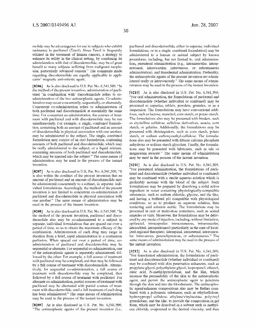
US 2007/014949.6 A1
molide may be advantageous for use in subjects who exhibit resistance to paclitaxel (Taxol). Since Taxol is frequently utilized in the treatment of human cancers, a strategy to enhance its utility in the clinical setting, by combining its administration with that of discodermolide, may be of great benefit to many subjects suffering from malignant neopla sias, particularly advanced cancers.” The comments made regarding discodermolide are equally applicable to appli cants’ magnetic anti-mitotic agent.
[0206] As is also disclosed in U.S. Pat. No. 6,541,509, “In the method of the present invention, administration of pacli taxel ‘in combination with discodermolide refers to co administration of the two antineoplastic agents. Co-admin istration may occur concurrently, sequentially, or alternately. Concurrent co-administration refers to administration of both paclitaxel and discodermolide at essentially the same time. For concurrent co-administration, the courses of treat ment with paclitaxel and with discodermolide may be run simultaneously. For example, a single, combined formula tion, containing both an amount of paclitaxel and an amount of discodermolide in physical association with one another, may be administered to the subject. The single, combined formulation may consist of an oral formulation, containing amounts of both paclitaxel and discodermolide, which may be orally administered to the subject, or a liquid mixture, containing amounts of both paclitaxel and discodermolide, which may be injected into the subject.” The same means of administration may be used in the process of the instant invention.
[0207] As is also disclosed in U.S. Pat. No. 6,541,509, “It is also within the confines of the present invention that an amount of paclitaxel and an amount of discodermolide may be administered concurrently to a subject, in separate, indi vidual formulations. Accordingly, the method of the present invention is not limited to concurrent co-administration of paclitaxel and discodermolide in physical association with one another.” The same means of administration may be used in the process of the instant invention.
[0208] As is also disclosed in U.S. Pat. No. 6,541,509, “In the method of the present invention, paclitaxel and disco dermolide also may be co-administered to a subject in separate, individual formulations that are spaced out over a period of time, so as to obtain the maximum efficacy of the combination. Administration of each drug may range in duration from a brief, rapid administration to a continuous perfusion. When spaced out over a period of time, co administration of paclitaxel and discodermolide may be sequential or alternate. For sequential co-administration, one of the antineoplastic agents is separately administered, fol lowed by the other. For example, a full course of treatment with paclitaxel may be completed, and then may be followed by a full course of treatment with discodermolide. Alterna tively, for sequential co-administration, a full course of treatment with discodermolide may be completed, then followed by a full course of treatment with paclitaxel. For alternate co-administration, partial courses of treatment with paclitaxel may be alternated with partial courses of treat ment with discodermolide, until a full treatment of each drug has been administered.” The same means of administration may be used in the process of the instant invention.
[0209] As is also disclosed in U.S. Pat. No. 6,541,509, “The antineoplastic agents of the present invention (i.e.,
30 Jun. 28, 2007
paclitaxel and discodermolide, either in separate, individual formulations, or in a single, combined formulation) may be administered to a human or animal subject by known procedures, including, but not limited to, oral administra tion, parenteral administration (e.g., intramuscular, intrap eritoneal, intravascular, intravenous, or subcutaneous administration), and transdermal administration. Preferably, the antineoplastic agents of the present invention are admin istered orally or intravenously.” The same means of admin istration may be used in the process of the instant invention.
[0210] As is also disclosed in U.S. Pat. No. 6,541,509, “For oral administration, the formulations of paclitaxel and discodermolide (whether individual or combined) may be presented as capsules, tablets, powders, granules, or as a suspension. The formulations may have conventional addi tives, such as lactose, mannitol, corn starch, or potato starch. The formulations also may be presented with binders, such as crystalline cellulose, cellulose derivatives, acacia, corn starch, or gelatins. Additionally, the formulations may be presented with disintegrators, such as corn starch, potato starch, or sodium carboxymethyl-cellulose. The formula tions also may be presented with dibasic calcium phosphate anhydrous or sodium starch glycolate. Finally, the formula tions may be presented with lubricants, such as talc or magnesium stearate.” The same means of administration may be used in the process of the instant invention.
[0211] As is also disclosed in U.S. Pat. No. 6,541,509, “For parenteral administration, the formulations of pacli taxel and discodermolide (whether individual or combined) may be combined with a sterile aqueous solution which is preferably isotonic with the blood of the subject. Such formulations may be prepared by dissolving a solid active ingredient in water containing physiologically-compatible substances, such as sodium chloride, glycine, and the like, and having a buffered pH compatible with physiological conditions, so as to produce an aqueous solution, then rendering said solution sterile. The formulations may be presented in unit or multi-dose containers, such as sealed ampules or vials. Moreover, the formulations may be deliv ered by any mode of injection, including, without limitation, epifascial, intracapsular, intracutaneous, intramuscular, intraorbital, intraperitoneal (particularly in the case of local ized regional therapies), intraspinal, intrasternal, intravascu lar, intravenous, parenchymatous, or subcutaneous.” The same means of administration may be used in the process of the instant invention.
[0212] As is also disclosed in U.S. Pat. No. 6,541,509, “For transdermal administration, the formulations of pacli taxel and discodermolide (whether individual or combined) may be combined with skin penetration enhancers, such as propylene glycol, polyethylene glycol, isopropanol, ethanol, oleic acid, N-methylpyrrolidone, and the like, which increase the permeability of the skin to the antineoplastic agent, and permit the antineoplastic agent to penetrate through the skin and into the bloodstream. The antineoplas tic agent/enhancer compositions also may be further com bined with a polymeric substance, such as ethylcellulose, hydroxypropyl cellulose, ethylene/vinylacetate, polyvinyl pyrrolidone, and the like, to provide the composition in gel form, which may be dissolved in a solvent such as methyl ene chloride, evaporated to the desired viscosity, and then

US 2007/014949.6 A1
applied to backing material to provide a patch.” The same means of administration may be used in the process of the instant invention.
[0213] As is also disclosed in U.S. Pat. No. 6,541,509, “It is within the confines of the present invention that the formulations of paclitaxel and discodermolide (whether individual or combined) may be further associated with a pharmaceutically-acceptable carrier, thereby comprising a pharmaceutical composition. The pharmaceutically-accept able carrier must be “acceptable” in the sense of being compatible with the other ingredients of the composition, and not deleterious to the recipient thereof. Examples of acceptable pharmaceutical carriers include Cremophor"M (a common vehicle for Taxol), as well as carboxymethyl cel lulose, crystalline cellulose, glycerin, gum arabic, lactose, magnesium stearate, methyl cellulose, powders, saline, sodium alginate, sucrose, starch, talc, and water, among others. Formulations of the pharmaceutical composition may conveniently be presented in unit dosage.” The same means of administration may be used in the process of the instant invention.
[0214] As is also disclosed in U.S. Pat. No. 6,541,509, “The formulations of the present invention may be prepared by methods well-known in the pharmaceutical art. For example, the active compound may be brought into asso ciation with a carrier or diluent, as a suspension or solution. Optionally, one or more accessory ingredients (e.g., buffers, flavoring agents, surface active agents, and the like) also may be added. The choice of carrier will depend upon the route of administration. The pharmaceutical composition would be useful for administering the antineoplastic agents of the present invention (i.e., paclitaxel and discodermolide, and their analogues and derivatives, either in separate, individual formulations, or in a single, combined formula tion) to a subject to treat neoplasia. The antineoplastic agents are provided in amounts that are effective to treat neoplasia in the subject. These amounts may be readily determined by the skilled artisan.” Similar formulations may be used in the process of the instant invention.
[0215] As is also disclosed in U.S. Pat. No. 6,541,509, “It is also within the confines of the present invention that paclitaxel and discodermolide be co-administered in com bination with radiation therapy or an antiangiogenic com pound (either natural or synthetic). Examples of antiangio genic compounds with which paclitaxel and discodermolide may be combined include, without limitation, angiostatin, tamoxifen, thalidomide, and thrombospondin.” Similar compositions may be used in the process of the instant invention.
[0216] As is also disclosed in U.S. Pat. No. 6,541,509, “The present invention further provides a synergistic com bination of antineoplastic agents. As defined above, ‘anti neoplastic’ refers to the ability to inhibit or prevent the development or spread of a neoplasm, and to limit, suspend, terminate, or otherwise control the maturation and prolif eration of cells in a neoplasm. As used herein, a “synergistic combination of antineoplastic agents” refers to a combina tion of antineoplastic agents that achieves a greater antine oplastic effect than would otherwise result if the antineoplas tic agents were administered individually. Additionally, as described above, the “antineoplastic agents” of the present invention are paclitaxel and discodermolide, and their ana
Jun. 28, 2007
logues and derivatives, either in separate, individual formu lations, or in a single, combined formulation. Administration of paclitaxel in combination with discodermolide unexpect edly results in a synergistic antineoplastic effect by provid ing greater efficacy than would result from use of either of the antineoplastic agents alone.” Similar synergistic combi nations may be used in the process of the instant invention.
[0217] As is also disclosed in U.S. Pat. No. 6,541,509, “In the synergistic combination of the present invention, pacli taxel and discodermolide may be combined in a single formulation, such that the amount of paclitaxel is in physical association with the amount of discodermolide. This single, combined formulation may consist of an oral formulation, containing amounts of both paclitaxel and discodermolide, which may be orally administered to the subject, or a liquid mixture, containing amounts of both paclitaxel and disco dermolide, which may be injected into the subject.” Similar synergistic combinations may be used in the process of the instant invention.
[0218] As is also disclosed in U.S. Pat. No. 6,541,509, “Alternatively, in the synergistic combination of the present invention, a separate, individual formulation of paclitaxel may be combined with a separate, individual formulation of discodermolide. For example, an amount of paclitaxel may be packaged in a vial or unit dose, and an amount of discodermolide may be packaged in a separate vial or unit dose. A synergistic combination of paclitaxel and discoder molide then may be produced by mixing the contents of the separate vials or unit doses in vitro. Additionally, a syner gistic combination of paclitaxel and discodermolide may be produced in vivo by co-administering to a subject the contents of the separate vials or unit doses, according to the methods described above. Accordingly, the synergistic com bination of the present invention is not limited to a combi nation in which amounts of paclitaxel and discodermolide are in physical association with one another in a single formulation.” Similar synergistic combinations may be used in the process of the instant invention.
[0219] As is also disclosed in U.S. Pat. No. 6,541,509, “The synergistic combination of the present invention com prises an effective antineoplastic amount of paclitaxel and an effective antineoplastic amount of discodermolide. As used herein, an “effective antineoplastic amount’ of paclitaxel or discodermolide is an amount of paclitaxel or discodermolide that is effective to ameliorate or minimize the clinical impairment or symptoms of neoplasia in a subject, in either a single or multiple dose. For example, the clinical impair ment or symptoms of neoplasia may be ameliorated or minimized by diminishing any pain or discomfort suffered by the subject; by extending the survival of the subject beyond that which would otherwise be expected in the absence of such treatment; by inhibiting or preventing the development or spread of the neoplasm; or by limiting, suspending, terminating, or otherwise controlling the matu ration and proliferation of cells in the neoplasm.” These comments are equally applicable to the process of the instant invention, in which discodermolide is replaced by the mag netic anti-mitotic compound of this invention.
[0220] As is also discussed in U.S. Pat. No. 6,541,509, “The effective antineoplastic amounts of paclitaxel and discodermolide will vary depending on the particular factors of each case, including the type of neoplasm, the stage of
US 2007/014949.6 A1
neoplasia, the subject’s weight, the severity of the subject’s condition, and the method of administration. For example, effective antineoplastic amounts of paclitaxel (Taxol) administered intraperitoneally may range from 1 to 10 mg/kg, and doses administered intravenously may range from 1 to 3 mg/kg, or from 135 mg/m2 to 200 mg/m2. Nevertheless, the appropriate effective antineoplastic amounts of paclitaxel and discodermolide can be readily determined by the skilled artisan.” These comments are equally applicable to the process of the instant invention, in which discodermolide is replaced by the magnetic anti mitotic compound of this invention [0221] As is also disclosed in U.S. Pat. No. 6,541,509, “The synergistic combination described herein may be use ful for treating neoplasia in a subject in need of treatment. Paclitaxel and discodermolide, which comprise the syner gistic combination of the present invention, may be co administered to a subject concurrently, sequentially, or alter nately, as described above. Moreover, the paclitaxel and discodermolide of the present invention may be adminis tered to a subject by any of the methods, and in any of the formulations, described above.” These comments are equally applicable to the process of the instant invention, in which discodermolide is replaced by the magnetic anti mitotic compound of this invention [0222] By way of yet further illustration, and referring to published United States patent application 2003/0235855 (the entire disclosure of which is hereby incorporated by reference into this specification), claims an assay for the detection of paclitaxel resistant cells in human tumors. Claim 4 of this published patent application, which is typical, claims: “An isolated tubulin amino acid sequence comprising an amino acid sequence having at least one mutation, the mutation selected from the group consisting of a mutation at position 210, a mutation at position 214, a mutation at position 215, a mutation at position 216, a mutation at position 217, a mutation at position 225, a mutation at position 228, a mutation at position 270, a mutation at position 273, a mutation at position 292, and a mutation at position 365 and any combination thereof.” [0223] At page 1 of published United States patent appli cation 2003/0235855, the importance of paclitaxel is dis cussed. It is disclosed that “Paclitaxel (Taxol), Taxotere and other paclitaxel-like drugs that are currently under develop ment hold great promise for the treatment of human cancer. Paclitaxel has shown remarkable activity against breast and ovarian cancer, melanomas, non-small lung carcinoma, eso phogeal cancer, Kaposi’s sarcoma, and some hematological malignancies. It has been described as the most significant antitumor drug developed in the last several decades and will, without doubt, find widespread use in the treatment of cancer. However, as is true of virtually all cancer chemo therapeutic drugs, patients responsive to paclitaxel eventu ally relapse due to the emergence of drug resistant tumor cells. Thus, there is a need in the art for methods to identify paclitaxel-resistant tumor cells, for agents that allow such identifications in a simple and cost effective way, and for methods for to treat patients with paclitaxel resistant tumor cells.” The solution presented to this problem in such published patent application is also described at page 1 thereof, wherein it is stated that: “The present invention involves polynucleotide mutations which confer paclitaxel resistance; mutant cells which are paclitaxel resistant; and
32 Jun. 28, 2007
methods to determine paclitaxel resistance. The present invention also provides a simple assay with sufficient sen sitivity to detect drug resistant cells in tumor biopsies by extracting polynucleotide from the tissue. The extracted polynucleotide is then hybridized to mutant-specific PCR primers and the mutant regions of tubulin are identified by selective amplification. Once identified, a secondary treat ment protocol can be administered to the patient to aid in tumor treatment.”
[0224] At pages 2 et seq. of published United States patent application 2003/00235855, the inventor discloses that “ . . . mutations able to convert resistance to paclitaxel are clustered in several small regions of beta-tubulin.” In para graphs 0022 et seq., it is disclosed that: “The inventor has found that mutations able to confer resistance to paclitaxel are clustered in several small regions of B-tubulin (Tables I-III) including 1210T, T214A, L215H, L215R, L215F, L215A, L215E, L215M, L215P. K216A, L217R, L217N, L217A, L225M, L228A, L228F. L228H, F270C. L273V. Q292H, and V365D. Of these 21 identified and sequenced mutant tubulins, 15 or 62% have a substitution at leucine including locations 215, 217, 225, 228 and 273. Of the 15 total leucine mutants, 7 or 46.7% occur at leu315, 3 or 20% occur at leu.217, 3 or 20% occur at leuz28, 1 or 6.7% occur at leu.225 and 1 or 6.7% occur at leuz73. The ability of 19 of the 21 total mutations to confer paclitaxel resistance has been confirmed by transfecting mutant clNAs into wild type cells.” [0225] It is also disclosed in published United States patent application 2003/0235855 (commencing at page 3 thereof) that: “The clustering of mutations affecting leucines is unusual and unexpected. Also unexpected is the three relatively localized regions of mutation, 210-217, 225-228, and 270-273, and two isolated sites of mutations, 292 and 365. Although some of these regions appear distant in the primary structure, they are actually close together in the tertiary structure of B-tubulin. The data support the hypoth esis that the mutations affect a critical interaction between tubulin subunits necessary for microtubule assembly and that the mechanism of paclitaxel is to facilitate this interac tion.” Thereafter, in the middle of page 3 of such patent application, Table 1 is presented. [0226] It is also disclosed in published United States patent application 2003/0235855 (commencing at page 3 thereof) that: “Table V below contains the corresponding fl-tubulin protein sequences for the variants listed in Table I: L215H (Seq. No. 10); L215R (Seq. No. 11); L215F (Seq. No. 12); L217R (Seq. No. 13); L228F (Seq. No. 14); and L228H (Seq. No. 15). All of these mutations result in amino acid substitutions at 3 leucine residues that are within 14 amino acids of one another.”
[0227] It is also disclosed in published United States patent application 2003/0235855 (commencing at page 3 thereof) that: “Using site-directed mutagenesis, the inventor has identified additional mutations in the H6/H7 loop of beta tubulin (that contains L215 and L217) that confer paclitaxel resistance. Table II lists the cell line, a portion of the encoding region including the mutated codon and the protein alteration.” Thereafer, Table II is presented on page 3 of the patent application.
[0228] It is also disclosed in published United States patent application 2003/0235855 (commencing at page 4

US 2007/014949.6 A1
thereof) that: “The corresponding 5-tubulin protein sequences (see Table IV) are: T214A (Seq. No. 24), L215A (Seq. No. 25), L215E (Seq. No. 26), L215M (Seq. No. 27), L215P (Seq. No. 28), K216A (Seq. No. 29), L217A (Seq. No. 30) and L228A (Seq. No. 31). The present invention also relates to probes having at least 12 bases including the codon for the particular amino acid substitution.” [0229] It is also disclosed in published United States patent application 2003/0235855 (commencing at page 3 thereof) that: “More recently, the inventor has found that the number of mutations that confer resistance to paclitaxel are likely to be small and that most are clustered in a small region of 5-tubulin. The likelihood that only a relatively small number of mutations will cause paclitaxel resistance is indicated by the observation that a random mutagenesis approach to find new mutations is recapitulating mutations that have already been found by classical genetics, and by the observation that mutations reported in different labora tories using different cell lines are beginning to show over lap. New mutants recently identified by the inventor in both CHO cells, and in the human KB3 cervical carcinoma cell line, are summarized in Table m. The fact that human mutations fall into the same region as the CHO mutations in the tertiary structure, combined with the observation that some mutations (not reported in this application) in CHO cells affect residues that are altered in human cell lines, supports the conclusion (based on identical amino acid sequences for fl-tubulin in the two species) that mutations identified in CHO cells are expected to confer drug resis tance in human cells. The nucleotide sequences encoding the new mutants are shown in Table III. 3 TABLE III” There after, Table III is represented on page 4. [0230] It is also disclosed in published United States patent application 2003/0235855 (commencing at page 4 thereof) that: “The new corresponding mutant CHO fl-tu bulin protein sequences (see Table IV) are: I210T (Ile to Thr at location 210) (Seq. No. 39), L217N (Leu to Asn at location 217) (Seq. No. 40), F270C (Phe to Cys at location 270) (Seq. No. 41) and Q292H (Gln to His at location 292) (Seq. No. 42). The new corresponding mutant human fl-tu bulin sequences are: L225M (Leu to Met at location 225) (Seq. No.43), L273V (Leu to Val at location 273) (Seq. No. 44) and V365D (Val to Asp at location 365) (Seq. No. 45).” [0231] It is also disclosed in published United States patent application 2003/0235855 (commencing at page 4 thereof) that: “Table IV lists all of the nucleic acid and protein sequences in sequence order that are described in this application along with their sequence id number and abbreviated amino acid mutation.” Thereafter, Table IV is presented on pages 4 et seq.
[0232] It is also disclosed in United States published patent application 2003/0235855 (commencing at page 8 thereof) that: “Because O-tubulin and 5-tubulin are similar proteins, similar clustering of mutations are anticipated in Cº-tubulin in paclitaxel resistant cells and O-tubulin PCR mutant primer sequences can be constructed in a similar manner to the primers presented herein for fl-tubulin in paclitaxel resistant tumor cells.” [0233] It is also disclosed in United States published patent application 2003/0235855 (commencing at page 8 thereof) that: “ The assays of the present invention were performed using Chinese hamster ovary (CHO) cells
Jun. 28, 2007
selected for resistance to paclitaxel. It is important to note that human and hamster tubulin have identical amino acid sequences and the nucleotide sequences are highly homolo gous and the nucleotide differences do not alter the amino acid sequence, and therefore, the amino acid changes found in mutant CHO cells will also confer resistance in humans.”
[0234] It is also disclosed in United States published patent application 2003/0235855 (commencing at page 8 thereof) that: “It has been established that the most frequent mechanism of resistance to paclitaxel occurs through muta tions in tubulin that affect the stability of the microtubules. These paclitaxel-resistant cells assemble less microtubule polymer and are frequently hypersensitive to other drugs such as vinblastine and vincristine that inhibit microtubule assembly.”
[0235] It is also disclosed in United States published patent application 2003/0235855 (commencing at page 8 thereof) that: “A model to explain these observations is provided in FIG. 1. The assay of the present invention can be used to identify many or most patients in danger of relapse due to tumor cell mutation and allow administration of alternate or additional treatment protocols using such agents as vinblastine or vincristine which are highly effec tive in eliminating the paclitaxel-resistant cells.”
[0236] It is also disclosed in United States published patent application 2003/0235855 (commencing at page 8 thereof) that: “The identification of the mutations and the clustering of mutations within the tubulin genes provide the data to construct highly efficient assays to detect these mutations in patients. Until now, there has been no method available to easily detect paclitaxel resistant cells in human tumors. The present methods or assays involve the design and use of allele-specific oligonucleotide primers for PCR.”
[0237] It is also disclosed in United States published patent application 2003/0235855 (commencing at page 8 thereof) that: “One such assay has been successfully con firmed for primers using the leuz17 to arg mutation shown in FIG. 2. The wild-type primer (CTCCGTAG GTGGGCGTGGTGA (Seq. No.46)) is able to amplify wild type DNA; but because of a 3’ mismatch with the mutant allele, it fails to amplify mutant DNA. Conversely, the mutant primer (CTCCGTAGGTGGGCGTGCGC (Seq. No. 47)) is able to amplify mutant DNA, but does not amplify the wild-type DNA because of 3' mismatch (underlined). The mutant primer also contains an intentional mismatch to both wild-type and mutant DNA at the third nucleotide from the 3' end (underlined) in order to enhance its allele specificity.” The aforementioned Seq. No. 46 and 47 are listed in this application’s sequence listing as SEQ. ID. No. 1 and 2 respectively.
[0238] It is also disclosed in United States published patent application 2003/0235855 (commencing at page 8 thereof) that: “Thus, allele-specific primers covering most potential mutations can be used individually or a ‘cocktails’ to detect the mutations in a single or very few PCR reactions. Alternatively, assays involving restriction enzyme digestion or allele-specific hybridization using the mutant DNA sequences can be used, but may lack the sensitivity and simplicity of the PCR assay.”
[0239] It is also disclosed in United States published patent application 2003/0235855 (commencing at page 9

US 2007/014949.6 A1
thereof) that: “The high frequency of mutations affecting only a few leucine residues of O-tubulin in paclitaxel resistant mutants was unexpected. Currently, there is no rational basis for predicting how an individual patient will respond to paclitaxel therapy. An initial assay of the tumor for mutations in tubulin that confer paclitaxel resistance would help clinicians decide whether the patient is a good candidate for paclitaxel therapy and save needless morbidity with a treatment that is unlikely to be effective. It would also allow the clinician to choose an alternative or additional therapy at an early time in the disease progression, thereby enhancing the survival of the patient.” [0240] It is also disclosed in United States published patent application 2003/0235855 (commencing at page 9 thereof) that: “Mammals express 60- and 63-tubulin genes, which are the targeted genes. To further optimize assays, it may be necessary to determine which tubulin isotype is involved in paclitaxel resistance for each type of tumor in certain instances. The tubulin is expressed in a tissue specific manner, with some forms restricted to certain tissues, which are widely disclosed in the prior art literature. Furthermore, the present inventors have found in CHO cells that the most abundant tubulin isotype is the one always involved in conferring resistance, which was completely unexpected. Thus, one skilled in the art must merely find the most abundant isotype for each type of tumor, which is disclosed in many technical journal and prior art references.” [0241] It is also disclosed in United States published patent application 2003/0235855 (commencing at page 9 thereof) that: “Paclitaxel is the prototype for a novel class of agents that inhibit cells in mitosis by promoting and stabi lizing microtubule assembly. Early studies with this com pound demonstrated that it binds to microtubules in a 1:1 stoichiometry with tubulin heterodimers (Manfredi, J. J., Parness, J., and Horwitz, S. B. (1981) J. Cell Biol. 94, 688-696) and inhibits microtubule disassembly. It is also able to induce microtubule assembly both in vitro and in vivo and induces microtubule bundle formation in treated cells (Schiff, P. B., Fant, J., and Horwitz, S. B. (1979) Nature 277, 665-667 and Schiff, P. B., and Horwitz, S. B. (1980) Proc. Natl. Acad. Sci. U.S.A. 77, 1561-1565). Recent inter est in this and related compounds has been fueled by clinical studies demonstrating remarkable activity of paclitaxel against a number of malignant diseases (Rowinsky, E. K., and Donehower, R. C. (1995) N. E. J. Med. 332, 1004 1014). Although still in clinical trials, the demonstrated activity of paclitaxel in phase II studies has led to FDA approval for its use in refractory cases of breast and ovarian cancer. As more patients are treated with this drug, clinical resistance is expected to become an increasingly significant problem.”
[0242] It is also disclosed in United States published patent application 2003/0235855 (commencing at page 9 thereof) that: “The mechanisms by which tumor cells acquire resistance to paclitaxel are not fully understood. Cell culture studies have shown that paclitaxel is a substrate for the multidrug resistance pump (gP170), and cells selected for high levels of resistance to the drug have increased gP170 (Casazza, A. M., and Fairchild, C. R. (1996) Cancer Treatment & Research 87, 149-71). Nevertheless, it has yet to be demonstrated that this mechanism is significant in paclitaxel refractory tumors. Indeed, the remarkable efficacy of paclitaxel in early clinical studies of patients who were
34 Jun. 28, 2007
pretreated with Adriamycin, a well known substrate for gP170, argues that the multidrug resistance (mdr) phenotype may not be as clinically prevalent as had initially been anticipated (Schiff, P. B., and Horwitz, S. B. (1980) Proc. Natl. Acad. Sci. U.S.A. 77, 1561-1565).” [0243] It is also disclosed in United States published patent application 2003/0235855 (commencing at page 9 thereof) that: “Additional mechanisms of resistance to pacli taxel have been reported. For example, several laboratories have provided evidence that changes in the expression of specific fl-tubulin genes are associated with paclitaxel resis tance in cultured tumor cell lines (Haber, M., Burkhart, C. A., Regl, D. L., Madafiglio, J., Norris, M. D., and Horwitz, S. B. (1995) J. Biol. Chem. 270, 31269-75; Jaffrezou, J. P., Dumontet, C., Derry, W. B., Duran, G., Chen, G., Tsuchiya, E., Wilson, L., Jordan, M. A., and Sikic, B. I. (1995) Oncology Res. 7, 517-27; Kavallaris, M., Kuo, D. Y. S., Burkhart, C. A., Regl, D. L., Norris, M. D., Haber, M., and Horwitz, S. B. (1997) J. Clin. Invest. 100, 1282-93; and Ranganathan, S., Dexter, D. W., Benetatos, C. A., and Hudes, G. R. (1998) Biochim. Biophys. Acta 1395, 237 245). More recently, a report describing mutations in fl-tu bulin that make the protein unresponsive to paclitaxel has appeared (Giannakakou, P., Sackett, D. L., Kang, Y.-K., Zhan, Z., Buters, J. T. M., Fojo, T., and Poruchynsky, M. S. (1997).J. Biol. Chem. 272, 17118-17125). To date, however, there is little evidence that any of the mechanisms described in cell culture cause paclitaxel resistance in human tumors.”
[0244] It is also disclosed in United States published patent application 2003/0235855 (commencing at page 9 thereof) that “The inventor’s own studies have described a resistance mechanism mediated by tubulin alterations that affect microtubule assembly (Cabral, F., and Barlow, S. B. (1991) Pharmac. Ther. 52, 159-171). Based on mutant properties and drug cross-resistance patterns, it is proposed that these changes in microtubule assembly could compen sate for the presence of the drug (Cabral, F., Brady, R. C., and Schibler, M. J. (1986) Ann. N.Y. Acad. Sci. 466, 745-756). The inventors were later able to directly demon strate that paclitaxel resistant Chinese hamster ovary (CHO) cells have diminished microtubule assembly compared to wild-type controls (Minotti, A. M., Barlow, S. B., and Cabral, F. (1991) J. Biol. Chem. 266, 3987-3994). Thus, isolation of paclitaxel resistant mutants provides an oppor tunity to study mutations that not only give information about the mechanisms of drug action and resistance, but also give structural information about regions of tubulin that are involved in assembly.”
[0245] It is also disclosed in United States published patent application 2003/0235855 (commencing at page 10 thereof) that: “The inventors have now sequenced 9 mutant fl-tubulin alleles and find that the mutations cluster at a site that is likely to be involved in lateral or longitudinal inter actions during microtubule assembly. Remarkably, these mutations are present in the H6H7 region of tubulin. Pre viously, it was believed that this region was not associated with paclitaxel binding. However, the inventors have iso lated mutants in the H6H7 region, which are directly related to paclitaxel resistance.”
[0246] It is also disclosed in United States published patent application 2003/0235855 (commencing at page 10 thereof) that: “There is some significance to the fact that all

US 2007/014949.6 A1
the mutated residues are leucines—it certainly indicates that the changes that produce taxol resistance are not random. One possibility is that the leucines define a structural motif (e.g., analogous to a leucine zipper, but clearly distinct) that forms an interaction site with a neighboring subunit. A more trivial explanation is that the leucines are among the least critical residues in the region and are therefore better able to tolerate changes that produce the kind of subtle alterations in tubulin assembly that give resistance to taxol. The fact that the 3 leucines are highly conserved throughout all species and that the conservation extends to alpha and even gamma tubulin would tend to argue for the former alternative, but it will take a lot of further experimentation before the true significance can be elucidated.” [0247] It is also disclosed in United States published patent application 2003/0235855 (commencing at page 10 thereof) that: “All 3 leucines in hamster are encoded by a CTC. Thus, a single base change can lead to substitution of histidine, arginine, phenylalanine, isoleucine, valine, or pro line. Only his, arg, and phe were isolated in the mutant cell lines. By transfection of cDNA altered by site-directed mutagenesis, is has been found that ile and val do not produce taxol resistance, probably because they do not perturb the structure of the microtubule sufficiently to pro duce resistance. Proline substitution can cause resistance, but appears to do so when expressed at very low levels. Moreover, the inventors have not been able to express it at high levels. This suggests that pro was not isolated in the mutant cell lines because it disrupts the structure of micro tubules too severely for the cells to survive.” [0248] It is also disclosed in United States published patent application 2003/0235855 (commencing at page 10 thereof) that: “The codons for leucine in human DNA are CTG at positions 215 and 217, and CTT at position 228. Single nucleotide changes will produce the same amino acid substitutions at 228, but a different set (valine, methionine, glutamine, arginine, or proline) at 215 and 217. Thus, 2 new possibilities (methionine and glutamine) might be found at 215 or 217 in human cells resistant to taxol. Of the two, methionine has been tested by transfection and it turns out to produce borderline resistance even at high levels of expression. A glutamine substitution has not yet been tested and should therefore be considered a presumptive candidate for producing resistance.” A Preferred Anti-Mitotic Compound [0249] In this section of the specification, a preferred compound is discussed. The preferred compound of this embodiment of the invention is an anti-mitotic compound. Anti-mitotic compounds are known to those skilled in the art. Reference may be had, e.g., to U.S. Pat. Nos. 6,723,858 (estrogenic compounds as anti-mitotic agents), 6,528,676 (estrogenic compounds as anti-mitotic agents), 6,350,777 (anti-mitotic agents which inhibit tubulin polymerization), 6,162,930 (anti-mitotic agents which inhibit tubulin poly merization), 5,892,069 (estrogenic compounds as anti-mi totic agents), 5,886,025 (anti-mitotic agents which inhibit tubulin polymerization), 5,661,143 (estrogenic compounds as anti-mitotic agents), 3,997,506 (anti-mitotic derivatives of thiocolchicine), and the like. The entire disclosure of each of these United States patents applications is hereby incor porated by reference into this specification. [0250] These prior art anti-mitotic agents may be modi fied, in accordance with the process of this invention, to
Jun. 28, 2007
make them “magnetic,” as that term is defined in this specification. In the next section of this specification, a process for modifying prior art taxanes to make them “magnetic” is described.
Preparation and Use of Magnetic Taxanes
[0251] In this portion of the specification, applicant will describe the preparation of certain magnetic taxanes that may be used in one or more of the processes of his invention. The process that is used to make such taxanes magnetic and/or water soluble may also be used to make other anti-mitotic compounds magnetic and/or water soluble.
[0252] In one embodiment of the invention, a biologically active substrate is linked to a magnetic carrier particle. An external magnetic field may then be used to increase the concentration of a magnetically linked drug at a predeter mined location.
[0253] One method for the introduction of a magnetic carrier particle involves the linking of a drug with a mag netic carrier. While some naturally occurring drugs inher ently carry magnetic particles (ferrimycin, albomycin, sal mycin, etc.), it is more common to generate a synthetic analog of the target drug and attach the magnetic carrier through a linker.
Functionalized Taxanes
[0254] Paclitaxel and docetaxel are members of the taxane family of compounds. A variety of taxanes have been isolated from the bark and needles of various yew trees
[0255] In one embodiment of the invention, such a linker is covalently attached to at least one of the positions in taxane.
R = Ac, R2 = PhCO, paclitaxel R1 = H, R2 = Boc, docetaxel

US 2007/014949.6 A1
-continued
RC) O OH
H5 # Ac R = H, 10-DEACETYLBACCATIN III R = Ac, BACCATIN III
[0256] It is well known in the art that the northern hemi sphere of taxanes has been altered without significant impact on the biological activity of the drug. Reference may be had to Chapter 15 of Taxane Anticancer Agents, Basic Science and Current Status, edited by G. George et al., ACS Sym posium Series 583, 207" National Meeting of the American Chemical Society, San Diego, Calif. (1994). Specifically the C-7, C-9, and C-10 positions of paclitaxel have been sig nificantly altered without degrading the biological activity of the parent compound. Likewise the C-4 position appears to play only a minor role. The oxetane ring at C-4 to C-5 has been shown to be critical to biological activity. Likewise, certain functional groups on the C-13 sidechain have been shown to be of particular importance.
[0257] In one embodiment of the invention, a position within paclitaxel is functionalized to link a magnetic carrier particle. A number of suitable positions are presented below. It should be understood that paclitaxel is illustrated in the figures below, but other taxane analogs may also be employed.
O AcO O OH
º NH Q
º ? is O OH PhCOO
Magnetic Carrier Attachment at C-4
O AcO O O-Magnetic Carrier
º NH Q º $ \ … O
E H5 = Acc) OH PhCOO
Attachment at C-7
36 Jun. 28, 2007
-continued Magnetic Carrier /
AcO Q
Attachment at C-7 and C-9
s O
Magnetic Carrier
O
Attachment at C-10
O OH
Attachment at C-4
Magnetic Carrier Attachment at C-19
Magnetic Carrier
Attachment at C-20
O

US 2007/014949.6 A1 37
[0258] C-4 taxane analogs have been previously generated in the art. A wide range of methodologies exist for the introduction of a variety of substituents at the C-4 position. By way of illustration, reference may be had to “Synthesis and Biological Evaluation of Novel C-4 Aziridine-Bearing Paclitaxel Analogs” by S. Chen et al., J. Med. Chem. 1995, vol 38, pp. 2263.
7-TES baccatin
(1) p-NO2C6H4OCOCI (2) Removal of C1, C7,
and C13 protecting groups (3) Protection of C7 (4) ethanolamine i
H DMSO
[0259] The secondary (C-13) and tertiary (C-1) alcohols of 7-TES baccatin were protected using the procedure of Chen (J. Org. Chem. 1994, vol. 59, p 6156) while simultaneously unmasking the alcohol at C-4. The resulting product was treated with a chloroformate to yield the corresponding carboxylate. Removal of the silyl protecting groups at C-1, C-7, and C-13, followed by selective re-protection of the C-7 position gave the desired activated carboxylate. The compound was then treated with a suitable nucleophile (in the author’s case, ethanolamine) to produce a C-4 function alized taxane. The C-13 sidechain was installed using stan dard lactam methodology.
[0260] This synthetic scheme thus provides access to a variety of C-4 taxane analogs by simply altering the nucleo phile used. In one embodiment of the instant invention, the nucleophile is selected so as to allow the attachment of a magnetic carrier to the C-4 position.
Attachment at C-7
[0261] The C-7 position is readily accessed by the proce dures taught in U.S. Pat. No. 6,610,860. The alcohol at the C-10 position of 10-deacetylbaccatin III was selectively protected. The resulting product was then allowed to react with an acid halide to produce the corresponding ester by selectively acylating the C-7 position over the C-13 alcohol.
Jun. 28, 2007
Standard lactam methodology allowed the installation of the C-13 sidechain. In another embodiment, baccatin III, as opposed to its deacylated analog, is used as the starting material.
(1) C-10 Protection (2) Propionyl chloride
HO # Ac
1()-DEACETYLEACCATIN III Naturally Occuring
lactam coupling –º
HO l B Z
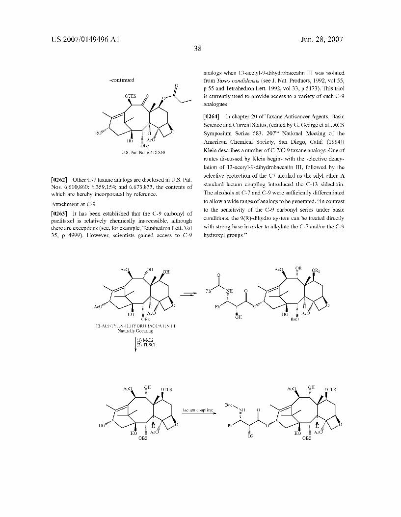
US 2007/014949.6 A1
-continued
OTES O
U.S. Pat. No. 6,610.860
[0262] Other C-7 taxane analogs are disclosed in U.S. Pat. Nos. 6,610,860; 6,359,154; and 6,673,833, the contents of which are hereby incorporated by reference. Attachment at C-9
[0263] It has been established that the C-9 carbonyl of paclitaxel is relatively chemically inaccessible, although there are exceptions (see, for example, Tetrahedron Lett. Vol 35, p. 4999). However, scientists gained access to C-9
AcO
w” AcON Ac
OBZ
13-ACETYL-9-DIHYDROBACCATIN III Naturally Occuring
HO
(1) Meli (2) TESCI
AcO OTES OH
38
lactam coupling –º
Jun. 28, 2007
analogs when 13-acetyl-9-dihydrobaccatin III was isolated from Taxus candidensis (see J. Nat. Products, 1992, vol 55, p 55 and Tetrahedron Lett. 1992, vol 33, p 5173). This triol is currently used to provide access to a variety of such C-9 analogues.
[0264] Science and Current Status, (edited by G. George et al., ACS Symposium Series 583, 207" National Meeting of the American Chemical Society, San Diego, Calif. (1994)) Klein describes a number of C-7/C-9 taxane analogs. One of
In chapter 20 of Taxane Anticancer Agents, Basic
routes discussed by Klein begins with the selective deacy lation of 13-acetyl-9-dihydrobaccatin III, followed by the selective protection of the C7 alcohol as the silyl ether. A standard lactam coupling introduced the C-13 sidechain. The alcohols at C-7 and C-9 were sufficiently differentiated to allow a wide range of analogs to be generated. “In contrast to the sensitivity of the C-9 carbonyl series under basic conditions, the 9(R)-dihydro system can be treated directly with strong base in order to alkylate the C-7 and/or the C-9 hydroxyl groups.”
AcO
Bzó

US 2007/014949.6 A1
[0265] One skilled in the art may adapt Klein’s general procedures to install a variety of magnetic carriers at these positions. Such minor adaptations are routine for those skilled in the art.
Attachment at C-7 and C-9
[0266] Klein also describes a procedure wherein 13-acetyl-9-dihydrobaccatin III is converted to 9-dihydro taxol. Reference may be had to “Synthesis of 9-Dihydro taxol: a Novel Bioactive Taxane” by L. L. Klein in Tetra hedron Lett. Vol 34, pp 20.47-2050. An intermediate in this synthetic pathway is the dimethylketal of 9-dihydrotaxol.
(1) 1,3-diol protection —º
(2) deacylation of C-13 (3) lactam coupling
HO # Ac
13–ACETYL-9-DIHYDROBACCATIN III Naturally Occuring
O
º NH Q
Ph2sº
[0267] followed with a carbonyl compound other than acetone to
In one embodiment, the procedure of Klein is
bind a wide variety of groups to the subject ketal. Supple mental discussion of C-9 analogs is found in “Synthesis of 9-Deoxotaxane Analogs” by L. L. Klein in Tetrahedron Lett. Vol 35, p.4707 (1994).
Attachment at C-10
[0268] position is functionalized using the procedure disclosed in U.S. Pat. No. 6,638,973. This patent teaches the synthesis of paclitaxel analogs that vary at the C-10 position. A sample
In one embodiment of the invention, the C-10
of 10-deacetylbaccatin III was acylated by treatment with propionic anhydride. The C-13 sidechain was attached using standard lactam methodology after first performing a selec tive protection of the secondary alcohol at the C-7 position. In one embodiment of the invention, this procedure is adapted to allow access to a variety of C-10 analogues of paclitaxel.
39 Jun. 28, 2007
(1) propionic anhydride CeCl3
(2) DMPSCI
H5 # Ac 1()-DEACETYLEACCATIN III
Naturally Occuring
lactam coupling
ODMPS
s s O HO l B Z
[0269] In one embodiment an anhydride is used as an electrophile. In another embodiment, an acid halide is used. As would be apparent to one of ordinary skill in the art, a variety of electrophiles could be employed.
O LG-Magnetic Carrier
- Magnetic Carrier LG = leaveing group LG
O O
}–º Carrier }—º Carrier H R
Siderophores
[0270] In one embodiment, a member of the taxane family of compounds is attached to a magnetic carrier particle. Suitable carrier particles include siderophores (both iron and non-iron containing), nitroxides, as well as other magnetic carriers.
[0271] Siderophores are a class of compounds that act as chelating agents for various metals. Most organisms use siderophores to chelate iron (III) although other metals may be exchanged for iron (see, for example, Exchange of Iron by Gallium in Siderophores by Emergy, Biochemistry 1986, vol 25, pages 4629-4633). Most of the siderophores known to date are either catecholates or hydroxamic acids.
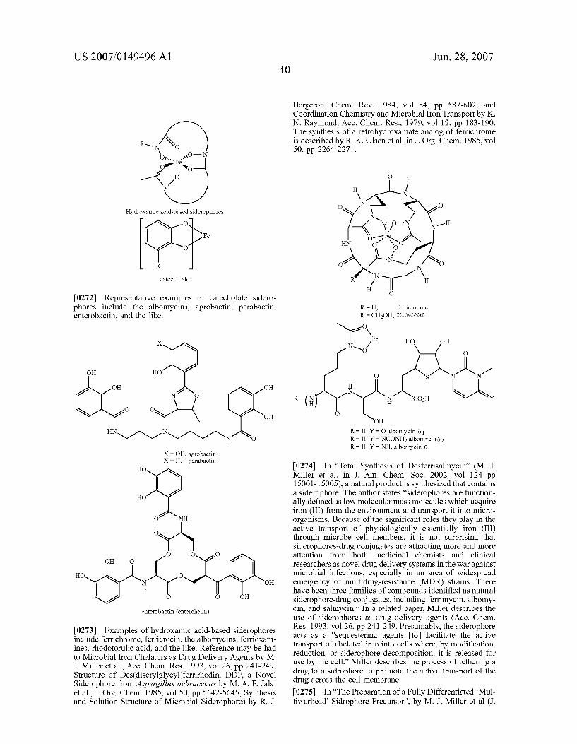
US 2007/014949.6 A1
Hydroxamic acid-based siderophores O
Fe
O
R 3
catecholate
[0272] Representative examples of catecholate sidero phores include the albomycins, agrobactin, parabactin, enterobactin, and the like.
OH HO
OH OH N*No
O O OH
HN *Svºs 2^ N O H
X = OH, agrobactin X = H, parabactin
HO
HO
O NH
O
O O O OH O
HO O OH
O O OH
enterobactin (enterchelin)
[0273] Examples of hydroxamic acid-based siderophores include ferrichrome, ferricrocin, the albomycins, ferrioxam ines, rhodotorulic acid, and the like. Reference may be had to Microbial Iron Chelators as Drug Delivery Agents by M. J. Miller et al., Acc. Chem. Res. 1993, vol 26, pp. 241-249; Structure of Des(diserylglycyl)ferrirhodin, DDF, a Novel Siderophore from Aspergillus ochraceous by M. A. F. Jalal et al., J. Org. Chem. 1985, vol 50, pp 5642-5645; Synthesis and Solution Structure of Microbial Siderophores by R. J.
40 Jun. 28, 2007
Bergeron, Chem. Rev. 1984, vol 84, pp 587-602; and Coordination Chemistry and Microbial Iron Transport by K. N. Raymond, Acc. Chem. Res., 1979, vol 12, pp 183-190. The synthesis of a retrohydroxamate analog of ferrichrome is described by R. K. Olsen et al. in J. Org. Chem. 1985, vol 50, pp. 2264-2271.
–3 * N-- - Fe In 92 sº y—?
O N O
H O
R = H, ferrichrome R = CH3OH, ferricrocin
Nº Fe HO OH Ns. A
O O
S O
H N
R—H N N CO2H H H
O OH
H, Y = O albomycin 31 H, Y = NCONH2 albomycin 82 H
R R R , Y = NH, albomycin a
[0274] In “Total Synthesis of Desferrisalmycin” (M. J. Miller et al. in J. Am. Chem. Soc. 2002, vol 124 pp 15001-15005), a natural product is synthesized that contains a siderophore. The author states “siderophores are function ally defined as low molecular mass molecules which acquire iron (III) from the environment and transport it into micro organisms. Because of the significant roles they play in the active transport of physiologically essentially iron (III) through microbe cell members, it is not surprising that siderophores-drug conjugates are attracting more and more attention from both medicinal chemists and clinical researchers as novel drug delivery systems in the war against microbial infections, especially in an area of widespread emergency of multidrug-resistance (MDR) strains. There have been three families of compounds identified as natural siderophore-drug conjugates, including ferrimycin, albomy cin, and salmycin.” In a related paper, Miller describes the use of siderophores as drug delivery agents (Acc. Chem. Res. 1993, vol 26, pp. 241-249. Presumably, the siderophore acts as a “sequestering agents [to] facilitate the active transport of chelated iron into cells where, by modification, reduction, or siderophore decomposition, it is released for use by the cell.” Miller describes the process of tethering a drug to a sidrophore to promote the active transport of the drug across the cell membrane. [0275] In “The Preparation of a Fully Differentiated “Mul tiwarhead' Sidrophore Precursor”, by M. J. Miller et al (J.

US 2007/014949.6 A1
Org. Chem. 2003, vol 68, pp 191-194) a precursor is disclosed which allows for a drug to be tethered to a sidrophore. In one embodiment, the route disclosed by Miller is employed to provide a variety of siderophores of similar structure. The synthesis of similar hydroxamic acid based siderophores is discussed in J. Org. Chem. 2000, vol 65 (Total Synthesis of the Siderophore Danoxamine by M. J. Miller et al.), pp. 4833-4838 and in the J. of Med. Chem. 1991, vol 32, pp. 968-978 (by M. J. Miller et al.).
[0276] A variety of fluorescent labels have been attached to ferrichrome analogues in “Modular Fluorescent-Labeled Siderophore Analogues” by A. Shanzer et al. in J. Med. Chem. 1998, vol 41, 1671–1678. The authors have devel oped a general methodology for such attachments.
fluorescent NH Esº"
O R |
fluorescent - ~'s Ns probe N – Linker O N OH H
O 3
[0277] As discussed above, functionalized ferrichrome analogs have been previous generated, usually using basic amine acids (glycine). In one embodiment, functionality is introduced using an alternative amine acid (such as serine) in place of the central glycine residue. This provides a functional group foothold from which to base a wide variety of analogs. Using traditional synthetic techniques, various linkers are utilized so as to increase or decrease the distance between the magnetic carrier and the drug.
O H
H / \ N
O N > N H HO-N 2’ Y (\on }J O
HN O HO \ O }~ O N O
--~~ )n / H H
Cl O
Jun. 28, 2007
[0278] As would be apparent to one of ordinary skill in the art, the above specified techniques are widely applicable to a variety of substrates. By way of illustration, and not limitation, a number of magnetic taxanes are shown below.
R2 = PhCO, paclitaxel analog R2 = Boc, docetaxel analog
Ac, R2 = PhCO, paclitaxel analog H, R2 = Boc, docetaxel analog
l 1

US 2007/014949.6 A1 42
-continued
R *>NH O
º - ; Fis \20 E. Hö = AcO OH BZC)
R1 = Ac, R2 = PhCO, paclitaxel analog R1 = H, R2 = Boc, docetaxel analog
R1O O OH
R2 `NH O
º ; Fis O # Hö E AcO ÖH Ö
O
H O
* \
R1 = Ac, R2 = PhCO, paclitaxel analog R1 = H, R2 = Boc, docetaxel analog
Nitroxides
[0279] Another class of magnetic carriers is the nitroxyl radicals (also known as nitroxides). Nitroxyl radicals a “persistent” radials that are unusually stable. A wide variety of nitroxyls are commercially available. Their paramagnetic nature allows them to be used as spin labels and spin probes.
Ö Ö Ö | | | N N N
OH O
TEMPO TEMPOL TEMPONE
Jun. 28, 2007
-continued Ö
sº 2. CO2Me
` NH2
TEMPAMINE TMOZ
[0280] In addition to the commercially available nitroxyls, other paramagnetic radical labels have been generated by acid catalyzed condensation with 2-Amino-2-methyl-1-pro panol followed by oxidation of the amine.
O
TSOH R2
R1 R2
O N
× So R1 R2
O-N O
R2 = PhCO, paclitaxel analog R2 = Boc, docetaxel analog
=Ac, R2 = PhCO, paclitaxel analog = H, R2 = Boc, docetaxel analog

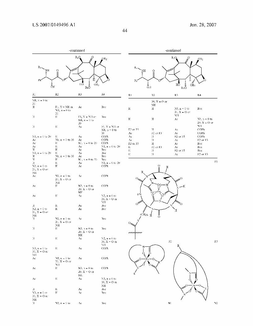

US 2007/014949.6 A1
-continued
R1 R2 R3 R4
O O
N N
O )n X
O )n
X = O, NH, NR, etc. N3
O
so X O
[0282] The prior disclosure illustrates how one may modify prior art taxanes to make them magnetic. As will be apparent to those skilled in the art, one may similarly modify other modifiable prior art anti-mitotic compounds to make them magnetic. Other Modifiable Prior Art Compounds [0283] Many anti-mitotic compounds that may be modi fied in accordance with the process of this invention are described in the prior art. One of these compounds is discodermolide; and it is described in U.S. Pat. No. 6,541, 509, the entire disclosure of which is hereby incorporated by reference into this specification. Reference may be had, e.g., to column 10 of such patent and to the references 10, 11, 12, and 13 cited in such patent. [0284] The reference 12 in U.S. Pat. No. 6,541,509 is to an article by R. J. Kowalski et al., “The Microtubule-Stabiliz ing Agent Discodermolide Competitively Inhibits the Bind ing of Paclitaxel (Taxol) to Tubulin Monomers, . . . .” Mol. Pharacol. 52:613-22, 1997. At page 2 of the Kowalski et al. patent, a formula for discodermolide is presented with 29 numbered carbon atoms (see FIG. 1).
Jun. 28, 2007
[0285] Elsewhere in this specification, applicants teach how to make “magnetic taxanes” by incorporating therein various linker groups and/or siderophores. The same linker groups and/or siderphores may be utilized via substantially the same process to make the discodermolide magnetic in the same manner.
[0286] As is disclosed elsewhere in this specification, siderphores are a class of compounds that act as chelating agents for various metals. When used to make “magnetic taxanes,” they are preferably bound to either the C7 and/or the C10 carbons of the paclitaxels. They can similarly be used to make “magnetic discodermolides,” but in this latter case they should be bonded at the C17 carbon of discoder molide, to which a hydroxyl group is bound. The same linker that is used to link the C7/C10 carbon of the taxane to the siderphore may also be sued to link the C-2 carbon of the discodermolde to the siderphore. [0287] In one embodiment, the “siderohophoric group” disclosed in U.S. Pat. No. 6,310,058, the entire disclosure of which is hereby incorporated by reference into this specifi cation, is utilized. The siderophoric group is of the for mula—(CH2), N(OH)—C(O)–(CH2)n-(CH=CH) = CH3, wherein m is an integer of from 2 to 6, n is 0 or an integer of from 1 to 22, and o is 0 or an integer 1 to 4, provided that m-Ho is no greater than 25. [0288] In another embodiment, “magentic epothilone A” and/or “magentic epotilone B’’ is also made by a similar process. As is also disclosed in the FIG. 1 of the Kowalski et al. article (see page 614), and in the formula depicted, the epothilone A exists when, in such formula, the alkyl group (“R”) is hydrogen, whereas the epothilone B exists when, in such formula, the alkyl group is methyl. In either case, one can make magnetic analogs of these compounds by using the same siderophores and the same linkers groups but utilizing them at a different site. One may bind such siderophores at either the number 3 carbon (which a hydroxyl group is bound) and/or the number 7 carbon (to which another hydroxyl group is bound.). [0289] Without wishing to be bound to any particular theory, applicants believe that the binding of the siderphores at the specified carbon sites imparts the required magnetic properties to such modified materials without adversely affecting the anti-mitotic properties of the material. In fact, in some embodiment, the anti-mitotic properties of the modified magnetic materials surpass the anti-mitotic prop erties of the unmodified materials.
[0290] This is unexpected; for, if the same linker groups and/or siderophores are used to bind to other than the specified carbon atoms, materials with no or substantially poorer anti-mitotic properties are produced. [0291] Thus, e.g., and referring to the magnetic taxanes described elsewhere in this specification (and also to FIG. 1 of the Kowalski et al. article), one should not link such siderphores to any carbons on the pendant aromatic rings. Thus, e.g., and referring to the discodermolide structure, one should not link siderphores to any of 1, 2, 3, or 4 carbon atoms. Thus, e.g., and referring to the epothilones, one should not link the siderphores to any carbon on the ring structure containing sulfur and nitrogen. [0292] By way of further illustration, and referring to U.S. Pat. Nos. 5,504,074, 5,661,143, 5,892,069, 6,528,676, and
US 2007/014949.6 A1
6,723,858 (the entire disclosure of each of which is hereby incorporated by reference into this specification), one may modify estradiol and estradiol metabolites to make them magnetic in accordance with the process of this invention. [0293] As is disclosed in U.S. Pat. No. 6,723,858 (the entire disclosure of which is hereby incorporated by refer ence into this specification, “Cell mitosis is a multi-step process that includes cell division and replication (Alberts, B. et al. In The Cell, pp. 652-661 (1989); Stryer, E. Bio chemistry (1988)). Mitosis is characterized by the intracel lular movement and segregation of organelles, including mitotic spindles and chromosomes. Organelle movement and segregation are facilitated by the polymerization of the cell protein tubulin. Microtubules are formed from alpha. and 5 tubulin polymerization and the hydrolysis of gua nosine triphosphate (GTP). Microtubule formation is impor tant for cell mitosis, cell locomotion, and the movement of highly specialized cell structures such as cilia and flagella.”
[0294] As is also disclosed in U.S. Pat. No. 6,723,858, “Microtubules are extremely labile structures that are sen sitive to a variety of chemically unrelated anti-mitotic drugs. For example, colchicine and nocodazole are anti-mitotic drugs that bind tubulin and inhibit tubulin polymerization (Stryer, E. Biochemistry (1988)). When used Cell mitosis is a multi-step process that includes cell division and replica tion (Alberts, B. et al. In The Cell, pp. 652-661 (1989); Stryer, E. Biochemistry (1988)). Mitosis is characterized by the intracellular movement and segregation of organelles, including mitotic spindles and chromosomes. Organelle movement and segregation are facilitated by the polymer ization of the cell protein tubulin. Microtubules are formed from alpha. and ?º tubulin polymerization and the hydrolysis of guanosine triphosphate (GTP). Microtubule formation is important for cell mitosis, cell locomotion, and the move ment of highly specialized cell structures such as cilia and flagella. Microtubules are extremely labile structures that are sensitive to a variety of chemically unrelated anti-mitotic drugs. For example, colchicine and nocodazole are anti mitotic drugs that bind tubulin and inhibit tubulin polymer ization (Stryer, E. Biochemistry (1988)). When used alone or in combination with other therapeutic drugs, colchicine may be used to treat cancer (WO-9303729-A, published Mar. 4, 1993; J 03240726-A, published Oct. 28, 1991), alter neu romuscular function, change blood pressure, increase sen sitivity to compounds affecting sympathetic neuron func tion, depress respiration, and relieve gout (Physician’s Desk Reference, Vol. 47, p. 1487, (1993)).” [0295] As is also disclosed in U.S. Pat. No. 6,723,858, “Estradiol and estradiol metabolites such as 2-methoxyestra diol have been reported to inhibit cell division (Seegers, J. C. et al. J. Steroid Biochem. 32, 797-809 (1989); Lottering, M-L, et al. Cancer Res. 52, 5926-5923(1992); Spicer, L. J. and Hammond, J. M. Mol. and Cell. Endo. 64, 119-126 (1989); Rao, P.N. and Engelberg, J. Exp. Cell Res.48, 71-81 (1967)). However, the activity is variable and depends on a number of in vitro conditions. For example, estradiol inhib its cell division and tubulin polymerization in some in vitro settings (Spicer, L. J. and Hammond, J. M. Mol. and Cell. Endo. 64, 119-126 (1989); Ravindra, R., J. Indian Sci. 64 (c) (1983)), but not in others (Lottering, M-L, et al. Cancer Res. 52, 5926-5923 (1992); Ravindra, R., J. Indian Sci. 64 (c) (1983)). Estradiol metabolites such as 2-methoxyestradiol will inhibit cell division in selected in vitro settings depend
46 Jun. 28, 2007
ing on whether the cell culture additive phenol red is present and to what extent cells have been exposed to estrogen. (Seegers, J. C. et al. Joint NCI-IST Symposium. Biology and Therapy of Breast Cancer. Sep. 25, Sep. 27, 1989, Genoa, Italy, Abstract A 58). alone or in combination with other therapeutic drugs, colchicine may be used to treat cancer (WO-9303729-A, published Mar. 4, 1993; J 03240726-A, published Oct. 28, 1991), alter neuromuscular function, change blood pressure, increase sensitivity to compounds affecting sympathetic neuron function, depress respiration, and relieve gout (Physician’s Desk Reference, Vol. 47, p. 1487, (1993)). [0296] As is also disclosed in U.S. Pat. No. 6,723,858, estradiol and estradiol metabolites such as 2-methoxyestra diol have been reported to inhibit cell division (Seegers, J. C. et al. J. Steroid Biochem. 32, 797-809 (1989); Lottering, M-L, et al. Cancer Res. 52, 5926-5923(1992); Spicer, L. J. and Hammond, J. M. Mol. and Cell. Endo. 64, 119-126 (1989); Rao, P.N. and Engelberg, J. Exp. Cell Res.48, 71-81 (1967)). However, the activity is variable and depends on a number of in vitro conditions. For example, estradiol inhib its cell division and tubulin polymerization in some in vitro settings (Spicer, L. J. and Hammond, J. M. Mol. and Cell. Endo. 64, 119-126 (1989); Ravindra, R., J. Indian Sci. 64 (c) (1983)), but not in others (Lottering, M-L. et al. Cancer Res. 52, 5926-5923 (1992); Ravindra, R., J. Indian Sci. 64 (c) (1983)). Estradiol metabolites such as 2-methoxyestradiol will inhibit cell division in selected in vitro settings depend ing on whether the cell culture additive phenol red is present and to what extent cells have been exposed to estrogen. (Seegers, J. C. et al. Joint NCI-IST Symposium. Biology and Therapy of Breast Cancer. Sep. 25, Sep. 27, 1989, Genoa, Italy, Abstract A 58). [0297] In one preferred embodiment, the modifiable anti mitotic agent is an anti-microtubule agent. In one aspect of this embodiment, and referring to U.S. Pat. No. 6,689,803 at columns 5-6 thereof (the entire disclosure of which patent is hereby incorporated by reference into this specification), representative anti-microtubule agents include, e.g., taxanes (e.g., paclitaxel and docetaxel), campothecin, eleutherobin, sarcodictyins, epothilones A and B. discodermolide, deute rium oxide (D2O), hexylene glycol (2-methyl-2,4-pen tanediol), tubercidin (7-deazaadenosine), LY290181 (2-amino-4-(3-pyridyl)-4H-naphtho(1,2-b)pyran-3-cardoni trile), aluminum fluoride, ethylene glycol bis-(succinimidyl succinate), glycine ethyl ester, nocodazole, cytochalasin B, colchicine, colcemid, podophyllotoxin, benomyl, oryzalin, majusculamide C, demecolcine, methyl-2-benzimidazole carbamate (MBC), LY195448, subtilisin, 1069C85, stega nacin, combretastatin, curacin, estradiol, 2-methoxyestra diol, flavanol, rotenone, griseofulvin, vinca alkaloids, including vinblastine and vincristine, maytansinoids and ansamitocins, rhizoxin, phomopsin A, ustiloxins, dolastatin 10, dolastatin 15, halichondrins and halistatins, spongist atins, cryptophycins, rhazinilam, betaine, taurine, isethion ate, HO-221, adociasulfate-2, estramustine, monoclonal anti-idiotypic antibodies, microtubule assembly promoting protein (taxol-like protein, TALP), cell swelling induced by hypotonic (190 mosmol/L) conditions, insulin (100 nmol/L) or glutamine (10 mmol/L), dynein binding, gibberelin, XCHO1 (kinesin-like protein), lysophosphatidic acid, lithium ion, plant cell wall components (e.g., poly-L-lysine and extensin), glycerol buffers, Triton X-100 microtubule stabilizing buffer, microtubule associated proteins (e.g.,

US 2007/014949.6 A1
MAP2, MAP4, tau, big tau, ensconsin, elongation factor-1 alpha (EF-1.alpha.) and E-MAP-115), cellular entities (e.g., histone H1, myelin basic protein and kinetochores), endog enous microtubular structures (e.g., axonemal structures, plugs and GTP caps), stable tubule only polypeptide (e.g., STOP145 and STOP220) and tension from mitotic forces, as well as any analogues and derivatives of any of the above. Within other embodiments, the anti-microtubule agent is formulated to further comprise a polymer.” [0298] The term “anti-microtubule,” as used in this speci fication (and in the specification of U.S. Pat. No. 6,689,803), refers to any “ . . . protein, peptide, chemical, or other molecule which impairs the function of microtubules, for example, through the prevention or stabilization of poly merization. A wide variety of methods may be utilized to determine the anti-microtubule activity of a particular com pound, including for example, assays described by Smith et al. (Cancer Lett 79(2):213–219, 1994) and Mooberry et al., (Cancer Lett. 96(2):261-266, 1995);” see, e.g., lines 13-21 of column 14 of U.S. Pat. No. 6,689,803. One preferred method, utilizing the anti-mitotic factor, is described in this specification. [0299] An extensive listing of anti-microtubule agents is provided in columns 14, 15, 16, and 17 of U.S. Pat. No. 6,689,803; and one or more of them may be modified them in accordance with the process of this invention to make them magnetic. These anti-microtubule agents include “ . . . taxanes (e.g., paclitaxel (discussed in more detail below) and docetaxel) (Schiff et al., Nature 277: 665-667, 1979; Long and Fairchild, Cancer Research 54:4355-4361, 1994; Ringel and Horwitz, J. Natl. Cancer Inst. 83(4): 288-291, 1991; Pazdur et al., Cancer Treat. Rev. 1904): 351-386, 1993), campothecin, eleutherobin (e.g., U.S. Pat. No. 5,473, 057), sarcodictyins (including sarcodictyin A), epothilones A and B (Bollag et al., Cancer Research 55: 2325-2333, 1995), discodermolide (ter Haar et al., Biochemistry 35: 243-250, 1996), deuterium oxide (D2O) (James and Lefe bvre, Genetics 130(2): 305-314, 1992; Sollott et al., J. Clin. Invest. 95; 1869-1876, 1995), hexylene glycol (2-methyl-2, 4-pentanediol) (Oka et al., Cell Struct. Funct. 16(2): 125 134, 1991), tubercidin (7-deazaadenosine) (Mooberry et al., Cancer Lett. 96(2): 261-266, 1995), LY290181 (2-amino-4 (3-pyridyl)-4H-naphtho(1,2-b)pyran-3-cardonitrile) (Panda et al., J. Biol. Chem. 272(12): 7681-7687, 1997; Wood et al., Mol. Pharmacol. 52(3): 437-444, 1997), aluminum fluoride (Song et al., J. Cell. Sci. Suppl. 14: 147-150, 1991), ethylene glycol bis-(succinimidylsuccinate) (Caplow and Shanks, J. Biol. Chem. 265(15): 8935–8941, 1990), glycine ethyl ester (Mejillano et al., Biochemistry 31(13): 3478-3483, 1992), nocodazole (Ding et al., J. Exp. Med. 171(3): 715-727, 1990; Dotti et al., J. Cell Sci. Suppl. 15: 75-84, 1991; Oka et al., Cell Struct. Funct. 16(2): 125-134, 1991; Weimer et al., J. Cell. Biol. 136(1), 71-80, 1997), cytochalasin B (Illinger et al., Biol. Cell 73(2-3): 131-138, 1991), colchi cine and CI 980 (Allen et al., Am. J. Physiol. 261(4 Pt. 1): L315-L321, 1991; Ding et al., J. Exp. Med. 171(3): 715-727, 1990; Gonzalez et al., Exp. Cell. Res. 1920): 10-15, 1991; Stargell et al., Mol. Cell. Biol. 12(4): 1443-1450, 1992; Garcia et al., Antican. Drugs 6(4): 533-544, 1995), colcemid (Barlow et al., Cell. Motil. Cytoskeleton 1901): 9-17, 1991; Meschini et al., J. Microsc. 176(Pt. 3): 204-210, 1994; Oka et al., Cell Struct. Funct. 16(2): 125-134, 1991), podophyl lotoxin (Ding et al., J. Exp. Med. 171(3): 715-727, 1990), benomy1 (Hardwick et al., J. Cell. Biol. 131(3): 709-720,
47 Jun. 28, 2007
1995; Shero et al., Genes Dev. 5(4): 549-560, 1991), oryza lin (Stargell et al., Mol. Cell. Biol. 12(4): 1443-1450, 1992), majusculamide C (Moore, J. Ind. Microbiol. 16(2): 134-143, 1996), demecolcine (Van Dolah and Ramsdell, J. Cell. Physiol. 166(1): 49-56, 1996; Wiemer et al., J. Cell. Biol. 136(1): 71-80, 1997), methyl-2-benzimidazolecarbamate (MBC) (Brown et al., J. Cell. Biol. 123(2): 387-403, 1993), LY195448 (Barlow & Cabral, Cell Motil. Cytoskel. 19: 9-17, 1991), subtilisin (Saoudi et al., J. Cell Sci. 108: 357-367, 1995), 1069C85 (Raynaud et al., Cancer Chemother. Pharmacol. 35: 169-173, 1994), steganacin (Hamel, Med. Res. Rev. 16(2): 207-231, 1996), combretast atins (Hamel, Med. Res. Rev. 16(2): 207-231, 1996), curacins (Hamel, Med. Res. Rev. 16(2): 207-231, 1996), estradiol (Aizu-Yokata et al., Carcinogen. 15(9): 1875-1879, 1994), 2-methoxyestradiol (Hamel, Med. Res. Rev. 16(2): 207-231, 1996), flavanols (Hamel, Med. Res. Rev. 16(2): 207-231, 1996), rotenone (Hamel, Med. Res. Rev. 16(2): 207-231, 1996), griseofulvin (Hamel, Med. Res. Rev. 16(2): 207-231; 1996), vinca alkaloids, including vinblastine and vincristine (Ding et al., J. Exp. Med. 171(3): 715-727, 1990; Dirk et al., Neurochem. Res. 15(11): 1135-1139, 1990; Hamel, Med. Res. Rev. 16(2): 207-231, 1996; Illinger et al., Biol. Cell 73(2-3): 131-138, 1991; Wiemer et al., J. Cell. Biol. 136(1): 71-80, 1997), maytansinoids and ansamitocins (Hamel, Med. Res. Rev. 16(2): 207-231, 1996), rhizoxin (Hamel, Med. Res. Rev. 16(2): 207-231, 1996), phomopsin A (Hamel, Med. Res. Rev. 16(2): 207-231, 1996), ustiloxins (Hamel, Med. Res. Rev. 16(2): 207-231, 1996), dolastatin 10 (Hamel, Med Res. Rev. 16(2): 207-231, 1996), dolastatin 15 (Hamel, Med. Res. Rev. 16(2): 207-231, 1996), halichon drins and halistatins (Hamel, Med. Res. Rev. 16(2): 207-231, 1996), spongistatins (Hamel, Med. Res. Rev. 16(2): 207 231, 1996), cryptophycins (Hamel, Med. Res. Rev. 16(2): 207-231, 1996), rhazinilam (Hamel, Med. Res. Rev. 16(2): 207-231, 1996), betaine (Hashimoto et al., Zool. Sci. 1: 195-204, 1984), taurine (Hashimoto et al., Zool. Sci. 1: 195-204, 1984), isethionate (Hashimoto et al., Zool. Sci. 1: 195-204, 1984), HO-221 (Ando et al., Cancer Chemother. Pharmacol. 37: 63-69, 1995), adociasulfate-2 (Sakowicz et al., Science 280: 292-295, 1998), estramustine (Panda et al., Proc. Natl. Acad. Sci. USA 94: 10560-10564, 1997), mono clonal anti-idiotypic antibodies (Leu et al., Proc. Natl. Acad. Sci. USA 91(22): 10690-10694, 1994), microtubule assem bly promoting protein (taxol-like protein, TALP) (Hwang et al., Biochem. Biophys. Res. Commun. 208(3): 1174-1180, 1995), cell swelling induced by hypotonic (190 mosmol/L) conditions, insulin (100 nmol/L) or glutamine (10 mmol/L) (Haussinger et al., Biochem. Cell. Biol. 72(1-2): 12-19, 1994), dynein binding (Ohba et al., Biochim. Biophys. Acta 1158(3): 323-332, 1993), gibberelin (Mita and Shibaoka, Protoplasma 119(1/2): 100-109, 1984), XCHO1 kinesin-like protein) (Yonetani et al., Mol. Biol. Cell 7(supply: 211A, 1996), lysophosphatidic acid (Cook et al., Mol. Biol. Cell 6(supply: 260A, 1995), lithium ion (Bhattacharyya and Wolff, Biochem. Biophys. Res. Commun. 73(2): 383-390, 1976), plant cell wall components (e.g., poly-L-lysine and extensin) (Akashi et al., Planta 182(3): 363-369, 1990), glycerol buffers (Schilstra et al., Biochem. J. 277(Pt. 3): 839-847, 1991: Farrell and Keates, Biochem. Cell. Biol. 68(11): 1256-1261, 1990; Lopez et al., J. Cell. Biochem. 43(3): 281-291, 1990), Triton X-100 microtubule stabilizing buffer (Brown et al., J. Cell Sci. 104(Pt. 2): 339-352, 1993; Safiejko-Mroczka and Bell, J. Histochem. Cytochem. 44(6):

US 2007/014949.6 A1
641-656, 1996), microtubule associated proteins (e.g., MAP2, MAP4, tau, big tau, ensconsin, elongation factor-1 alpha EF-1.alpha.) and E-MAP-115) (Burgess et al., Cell Motil. Cytoskeleton 2004): 289-300, 1991; Saoudi et al., J. Cell. Sci. 108(Pt. 1): 357-367, 1995; Bulinski and Bossler, J. Cell. Sci. 107(Pt. 10): 2839-2849, 1994; Ookata et al., J. Cell Biol. 128(5): 849–862, 1995; Boyne et al., J. Comp. Neurol. 358(2): 279-293, 1995; Ferreira and Caceres, J. Neurosci. 11(2): 392400, 1991; Thurston et al., Chromo soma 105(1): 20-30, 1996; Wang et al., Brain Res. Mol. Brain. Res. 38(2): 200-208, 1996; Moore and Cyr, Mol. Biol. Cell 7(supply: 221-A, 1996; Masson and Kreis, J. Cell Biol. 123(2), 357-371, 1993), cellular entities (e.g. histone H1, myelin basic protein and kinetochores) (Saoudi et al., J. Cell. Sci. 108(Pt. 1): 357-367, 1995; Simerly et al., J. Cell Biol. 111(4): 1491-1504, 1990), endogenous microtubular structures (e.g., axonemal structures, plugs and GTP caps) (Dye et al., Cell Motil. Cytoskeleton 21(3): 171-186, 1992; Azhar and Murphy, Cell Motil. Cytoskeleton 15(3): 156 161, 1990; Walker et al., J. Cell Biol. 114(1): 73-81, 1991; Drechsel and Kirschner, Curr. Biol. 4(12): 1053-1061, 1994), stable tubule only polypeptide (e.g., STOP 145 and STOP220) (Pirollet et al., Biochim. Biophys. Acta 1160(1): 113-119, 1992; Pirollet et al., Biochemistry 31(37): 8849 8855, 1992; Bosc et al., Proc. Natl. Acad. Sci. USA 93(5): 2125-2130, 1996; Margolis et al., EMBO J. 9(12): 4095 4102, 1990) and tension from mitotic forces (Nicklas and Ward, J. Cell Biol. 126(5): 1241-1253, 1994), as well as any analogues and derivatives of any of the above. Such com pounds can act by either depolymerizing microtubules (e.g., colchicine and vinblastine), or by stabilizing microtubule formation (e.g., paclitaxel).”
[0300] U.S. Pat. No. 6,689,803 also discloses (at columns 16 and 17 that, “Within one preferred embodiment of the invention, the anti-mitotic compound is paclitaxel, a com pound which disrupts microtubule formation by binding to tubulin to form abnormal mitotic spindles. Briefly, paclitaxel is a highly derivatized diterpenoid (Wani et al., J. Am. Chem. Soc. 93:2325, 1971) which has been obtained from the harvested and dried bark of Taxus brevifolia (Pacific Yew) and Taxomyces Andreanae and Endophytic Fungus of the Pacific Yew (Stierle et al., Science 60:214-216,-1993). “Paclitaxel” (which should be understood herein to include prodrugs, analogues and derivatives such as, for example, TAXOLR, TAXOTERER, Docetaxel, 10-desacetyl ana logues of paclitaxel and 3'N-desbenzoyl-3'N-t-butoxy car bonyl analogues of paclitaxel) may be readily prepared utilizing techniques known to those skilled in the art (see e.g., Schiff et al., Nature 277:665-667, 1979; Long and Fairchild, Cancer Research 54:4355-4361, 1994; Ringel and Horwitz, J. Natl. Cancer Inst. 83(4):288-291, 1991; Pazdur et al., Cancer Treat. Rev. 1904):351-386, 1993; WO94/ 07882; WO94/07881: WO94/07880, WO94/07876; WO93/ 23555; WO93/10076; WO94/00156; WO93/24476: EP590267; WO94/20089; U.S. Pat. Nos. 5,294,637; 5,283, 253, 5,279,949; 5,274,137; 5,202,448; 5,200,534; 5,229, 529; 5,254,580; 5,412,092; 5,395,850: 5,380,751; 5,350, 866; 4,857,653: 5,272,171; 5,411,984; 5,248,796; 5,248, 796; 5,422.364; 5,300,638; 5,294,637; 5,362,831; 5,440, 056; 4,814,470; 5,278.324; 5,352,805; 5,411,984; 5,059. 699, 4,942,184; Tetrahedron Letters 35(52):9709-9712, 1994; J. Med. Chem. 35:4230-4237, 1992; J. Med. Chem. 34:992-998, 1991; J. Natural Prod. 57(10): 1404-1410, 1994; J. Natural Prod. 57(11):1580–1583, 1994; J. Am. Chem. Soc.
48 Jun. 28, 2007
110:6558-6560, 1988), or obtained from a variety of com mercial sources, including for example, Sigma Chemical Co., St. Louis, Mo. (T7402—from Taxus brevifolia).” [0301] As is also disclosed in U.S. Pat. No. 6,689,893, “Representative examples of such paclitaxel derivatives or analogues include 7-deoxy-docetaxol. 7,8-cyclopropatax anes, N-substituted 2-azetidones, 6,7-epoxy paclitaxels, 6,7 modified paclitaxels, 10-desacetoxytaxol, 10-deacetyltaxol (from 10-deacetylbaccatin III), phosphonooxy and carbon ate derivatives of taxol, taxol. 2',7-di(sodium 1,2-benzene dicarboxylate, 10-desacetoxy-11,12-dihydrotaxol-10, 12(18)-diene derivatives, 10-desacetoxytaxol, Protaxol (2' and/or 7-O-ester derivatives), (2’- and/or 7-O-carbonate derivatives), asymmetric synthesis of taxol side chain, fluoro taxols, 9-deoxotaxane, (13-acetyl-9-deoxobaccatine III, 9-deoxotaxol, 7-deoxy-9-deoxotaxol, 10-desacetoxy-7 deoxy-9-deoxotaxol, Derivatives containing hydrogen or acetyl group and a hydroxy and tert-butoxycarbonylamino, sulfonated 2'-acryloyltaxol and sulfonated 2'-O-acyl acid taxol derivatives, succinyltaxol. 2'-gamma.-aminobutyryl taxol formate, 2'-acetyl taxol, 7-acetyl taxol, 7-glycine car bamate taxol. 2'-OH-7-PEG(5000)carbamate taxol. 2'-ben zoyl and 2',7-dibenzoyl taxol derivatives, other prodrugs (2'-acetyl taxol; 2',7-diacetyltaxol; 2'succinyltaxol; 2'-(beta alanyl)-taxol); 2'gamma-aminobutyryltaxol formate; ethyl ene glycol derivatives of 2'-succinyltaxol; 2'-glutaryltaxol; 2'-(N,N-dimethylglycyl)taxol; 2'-(2-(N,N-dimethylamino )propionyl)taxol; 2'orthocarboxybenzoyl taxol; 2'aliphatic carboxylic acid derivatives of taxol, Prodrugs {2'(N,N diethylaminopropionyl)taxol. 2'(N,N-dimethylglycyl)taxol, 7(N,N-dimethylglycyl)taxol. 2',7-di-(N,N-dimethylglycyl )taxol, 7(N,N-diethylaminopropionyl)taxol. 2",7-di(N,N-di ethylaminopropionyl)taxol. 2'-(L-glycyl)taxol, 7-(L-glycyl )taxol. 2',7-di(L-glycyl)taxol. 2'-(L-alanyl)taxol, 7-(L alanyl)taxol, 2',7-di(L-alanyl)taxol. 2'-(L-leucyl)taxol, 7-(L leucyl)taxol, 2',7-di(L-leucyl)taxol, 2’-(L-isoleucyl)taxol, 7-(L-isoleucyl)taxol. 2',7-di(L-isoleucyl)taxol, 2’-(L-valyl )taxol, 7-(L-valyl)taxol, 27-di(L-valyl)taxol. 2'-(L-phenyla lanyl)taxol, 7-(L-phenylalanyl)taxol. 2',7-di(L-phenylala nyl)taxol. 2'-(L-prolyl)taxol, 7-(L-prolyl)taxol. 2',7-di(L prolyl)taxol, 2’-(L-lysyl)taxol, 7-(L-lysyl)taxol. 2',7-di(L lysyl)taxol. 2'-(L-glutamyl)taxol, 7-(L-glutamyl)taxol. 2',7 di(L-glutamyl)taxol. 2'-(L-arginyl)taxol, 7-(L-arginyl)taxol, 2,7-di(L-arginyl)taxol}, Taxol analogs with modified phe nylisoserine side chains, taxotere, (N-debenzoyl-N-tert-(bu toxycaronyl)-10-deacetyltaxol, and taxanes (e.g., baccatin III, cephalomannine, 10-deacetylbaccatin III, brevifoliol, yunantaxusin and taxusin).” [0302] By way of yet further illustration, one may use one or more of the anti-mitotic agents disclosed in U.S. Pat. Nos. 6,673,937 (syntheses and methods of use of new antimitotic agents), 6,624,317 (taxoid conjugates as antimitotic and antitumor agents), 6,593,334 (camptothecin-taxoid conju gates as antimitotic and antitumor agents), 6,593,321 (2-alkoxyestradiiol analogs with antiproliferative and anti mitotic activity), 6,569,870 (fluorinated quinolones as anti mitotic and antitumor agent), 6,528,489 (mycotoxin deriva tives as antimitotic agents), 6,392,055 (synthesis and biological evaluation of analogs of the antimitotic marine natural product curacin A), 6,127,377 (vinka alkaloid anti mitotic halogenated derivatives), 5,695,950 (method of screening for antimitotic compounds using the cdc25 tyrosine phosphatase), 5,620,985 (antimitotic binary alka loid derivatives from catharanthus roseus), 5,294,538

US 2007/014949.6 A1
(method of screening for antimitotic compounds using the CDC tyrosine phosphatase), and the like. The entire disclo sure of each of these United States patents is hereby incor porated by reference into this specification. [0303] As will be apparent, one or more of the aforemen tioned anti-mitotic and/or anti-microtubule agents may be modified to make them magnetic in accordance with this invention.
Synergistic Combinations of Magnetic Anti-Mitotic Agents [0304] In one embodiment of this invention, discussed elsewhere in this specification, a synergistic combination of the magnetic anti-mitotic compound of this invention and paclitaxel is described. In the embodiment of the invention described in this section of the specification, a synergetic combination of two or more anti-mitotic compounds is described.
[0305] In one embodiment, the first anti-mitotic com pound is preferably a magentic taxane such as, e.g., magen tic paclitaxel and/ormagnetic docetaxel. In this embodiment, the second anti-mitotic compound may be magnetic disco dermolide, and/or magnetic epothilone A, and/or magentic epothilone B, and/or mixtures thereof. Other suitable com binations of magnetic anti-mitotic agents will be apparent. Properties of the Preferred Anti-Mitotic Compounds [0306] In one preferred embodiment, the compound of this invention has a mitotic index factor of at least about 10 percent and, more preferably, at least about 20 percent. In one aspect of this embodiment, the mitotic index factor is at least about 30 percent. In another embodiment, the mitotic index factor is at least about 50 percent. [0307] In another embodiment of the invention, the com pound of this invention has a mitotic index factor of less than about 5 percent.
[0308] As is known to those skilled in the art, the mitotic index is a measure of the extent of mitosis. Reference may be had, e.g., to U.S. Pat. Nos. 5,262,409 (binary tumor therapy), 5,443,962 (methods of identifying inhibitors of cdc25 phosphatase), 5,744,300 (methods and reagents for the identification and regulation of senescence-related genes), 6,613,318, 6,251,585 (assay and reagents for iden tifying anti-proliferative agents), 6,252,058 (sequences for targeting metastatic cells), 6,387,642 (method for identify ing a reagent that modulates Myt1 activity), 6,413,735 (method of screening for a modulator of angiogenesis), 6,531,479 (anti-cancer compounds), 6,599,694 (method of characterizing potential therapeutics by determining cell cell interactions), 6,620,403 (in vivo chemosensitivity screen for human tumors), 6,699,854 (anti-cancer com pounds), 6,743,576 (database system for predictive cellular bioinformatics), and the like. The entire disclosure of each of these United States patents is hereby incorporated by reference into this specification. [0309] Reference may also be had, e.g., to U.S. Pat. No. 5,262,409, which discloses that: “Determination of mitotic index: For testing mitotic blockage with nocodazole and taxol, cells were grown a minimum of 16 hours on polyl ysinecoated glass coverslips before drug treatment. Cells were fixed at intervals, stained with antibodies to detect lamin B, and counterstained with propidium iodide to assay chromosome condensation. To test cell cycle blocks in
49 Jun. 28, 2007
interphase, cells were synchronized in mitosis by addition of nocodazole (Sigma Chemical Co.) to a final concentration of 0.05 pg/ml from a 1 mg/ml stock in dimethylsulfoxide. After 12 hours arrest, the mitotic subpopulation was isolated by shakeoff from the culture plate. After applying cell cycle blocking drugs and/or 2-A.P. cells were fixed at intervals, prepared for indirect immunofluorescence with anti-tubulin antibodies, and counterstained with propidium iodide. All data timepoints represent averages of three counts of greater than 150 cells each. Standard deviation was never more than 1.5% on the ordinate scale.”
[0310] Reference may be had, e.g., to U.S. Pat. No. 6,413,735 which discloses that: “The mitotic index is deter mined according to procedures standard in the art. Keram et al., Cancer Genet. Cytogenet. 55:235 (1991). Harvested cells are fixed in methanol:acetic acid (3:1, viv), counted, and resuspended at 106 cells/ml in fixative. Ten microliters of this suspension is placed on a slide, dried, and treated with Giemsa stain. The cells in metaphase are counted under a light microscope, and the mitotic index is calculated by dividing the number of metaphase cells by the total number of cells on the slide. Statistical analysis of comparisons of mitotic indices is performed using the 2-sided paired t-test.” [0311] By means of yet further illustration, one may measure the mitotic index by means of the procedures described in, e.g., articles by Keila Torres et al. (“Mecha nisms of Taxol-Induced Cell Death are Concentration Dependent,” Cancer Research 58, 3620-3626, Aug. 15, 1998), and Jie-Gung Chen et al. (“Differential Mitosis Responses to Microtubule-stabilizing and destabilizing Drugs,” Cancer Research 62, 1935-1938, Apr. 1, 2002). [0312] The mitotic index is preferably measured by using the well-known HeLa cell lines. As is known to those skilled in the art, HeLa cells are cells that have been derived from a human carcinoma of the cervix from a patient named Henrietta Lack; the cells have been maintained in tissued culture since 1953.
[0313] Hela cells are described, e.g., in U.S. Pat. Nos. 5,811,282 (cell lines useful for detection of human immu nodeficiency virus), 5,376,525 (method for the detection of mycoplasma), 6,143,512, 6,326,196, 6,365,394 (cell lines and constructs useful in production of E-1 deleted adenovi ruses), 6,440,658 (assay method for determining effect on adenovirus infection of Hela cellsó,461,809 (method of improving infectivity of cells for viruses), 6,596,535, 6,605, 426, 6,610,493 (screening compounds for the ability to alter the production of amyloid-beta-peptide), 6,699,851 (cyto toxic compounds and their use), and the like; the entire disclosure of each of these United States patents is hereby incorporated by reference into this specification. By way of illustration, 6,440,658 discloses that, for the experiments described in such patent, “The HeLa cell line was obtained from the American Type Culture Collection, Manassas Va.” [0314] In one preferred embodiment, the mitotic index of a “control cell line” (i.e., one that omits that drug to be tested) and of a cell line that includes 50 nanomoles of such drug per liter of the cell line are determined and compared. The “mitotic index factor” is equal to (Mt–Mc/Mc)×100, wherein Mc is the mitotic index of the “control cell line,” and Mt is the mitotic index of the cell line that includes the drug to be tested. [0315] The compound of this invention preferably has a molecular weight of at least about 150 grams per mole. In

US 2007/014949.6 A1
one embodiment, the molecular weight of such compound is at least 300 grams per mole. In another embodiment, the molecular weight of such compound is 400 grams per mole. In yet another embodiment, the molecular weight of such compound is at least about 550 grams per mole. In yet another embodiment, the molecular weight of such com pound is at least about 1,000 grams per mole. In yet another embodiment, the molecular weight of such compound is at least 1,200 grams per mole.
[0316] The compound of this invention preferably has a positive magnetic susceptibility of at least 1,000×107° cen timeter-gram-seconds (cgs). As is known to those skilled in the art, magnetic susceptibility is the ratio of the magneti zation of a material to the magnetic filed strength. Reference may be had, e.g., to U.S. Pat. Nos. 3,614,618 (magnetic susceptibility tester), 3,644,823 (nulling coil apparatus for magnetic susceptibility logging), 3,657,636 (thermally stable coil assembly for magnetic susceptibility logging), 3,665,297 (apparatus for determining magnetic susceptibil ity in a controlled chemical and thermal environment), 3,758,847 (method and system with voltage cancellation for measuring the magnetic susceptibility of a subsurface earth formation), 3,758,848 (magnetic susceptibility well logging system), 3,879,658 (apparatus for measuring magnetic sus ceptibility), 3,890,563 (magnetic susceptibility logging apparatus for distinguishing ferromagnetic materials), 3,980,076 (method for measuring externally of the human body magnetic susceptibility changes), 4,079,730 (apparatus for measuring externally of the human body magnetic sus ceptibility changes), 4,277,750 (induction probe for the measurement of magnetic susceptibility), 4,359,399 (tag gands with induced magnetic susceptibility), 4,507,613 (method for identifying non-magnetic minerals in earth formations utilizing magnetic susceptibility measurements), 4,662,359 (use of magnetic susceptibility probes in the treatment of cancer), 4,701,712 (thermoregulated magnetic susceptibility sensor assembly), 5,233,992 (MRI method for high liver iron measurement using magnetic susceptibility induced field distortions), 6,208,884 (noninvasive room temperature instrument to measure magnetic susceptibility variations in body tissue), 6,321,105 (contrast agents with high magnetic susceptibility), 6,477,398 (resonant magnetic susceptibility imaging), and the like. The entire disclosure of each of these United States patent applications is hereby incorporated by reference into this specification.
[0317] In one embodiment, the compound of this inven tion has a positive magnetic susceptibility of at least 5,000× 107° cys. In another embodiment, such compound has a positive magnetic susceptibility of at least 10,000×107° cgs. [0318] The compound of this invention is preferably com prised of at least 7 carbon atoms and, more preferably, at least about 10 carbon atoms. In another embodiment, such compound is comprised of at least 13 carbon atoms and at least one aromatic ring; in one aspect of this embodiment, the compound has at least two aromatic rings. In another embodiment, such compound is comprised of at least 17 carbon atoms.
[0319] In one embodiment, the compound of this inven tion is comprised of at least one oxetane ring. As is dis closed, e.g., on page 863 of N. Iving Sax’s “Hawley’s Condensed Chemical Dictionary.” Eleventh Edition (Van Nostrand Reinhold Company, New York, N.Y., 1987), the
50 Jun. 28, 2007
oxetane group, also known as “trimethylene oxide), is identified by chemical abstract number CAS. 503-30-0. The oxetane group present in the preferred compound preferably is unsubstituted. In one embodiment, however, one or more of the ring carbon atoms (either carbon number one, or carbon number two, or carbon number 3), has one or more of its hydrogen atoms substituted by a halogen group (such as chlorine), a lower alkyl group of from 1 to 4 carbon atoms, a lower haloalkyl group of from 1 to 4 carbon atoms, a cyanide group (CN), a hydroxyl group, a carboxyl group, an amino group (which can be primary, secondary, or teriarary and may also contain from 0 to 6 carbon atoms), a substituted hydroxyl group (such as, e.g., an ether group containing from 1 to 6 carbon atoms), and the like. In one aspect of this embodiment, the substituted oxetane group is 3,3-bis(chlormethyl)oxetane.
[0320] In one embodiment, the compound of this inven tion is comprised of from about 1 to 10 groups of the formula –OB, in which B is selected from the group consisting of hydrogen, alkyl of from about 1 to about 5 carbon atoms, and a moiety of the formula R-(C=0)—O—, wherein R is selected from the group consisting of hydrogen and alkyl of from about 1 to about 6 carbon atoms, and the carbon is bonded to the R moiety, to the double-bonded oxygen, and to the single bonded oxygen, thereby forming what is commonly known as an acetyl group. This acetyl group preferably is linked to a ring structure that is unsaturated and preferably contains from about 6 to about 10 carbon atoms. [0321] In one embodiment, the compound is comprised of two unsaturated ring structures linked by an amide structure, which typically has an acyl group, —CONR) –, wherein R, is selected from the group consisting of hydrogen lower alkyl of from 1 to about 6 carbon atoms. In one preferred embodiment, the N group is bonded to both to the Ri group and also to radical that contains at least about 20 carbon atoms and at least about 10 oxygen atoms. [0322] In one embodiment, the compound of this inven tion contains at least one saturated ring comprising from about 6 to about 10 carbon atoms. By way of illustration, the saturated ring structures may be one or more cyclohexane rings, cyclopheptane rings, cyclooctane rings, cylclononane rings, and/or cylcodecane rings. In one preferred aspect of this embodiment, at least one saturated ring in the compound is bonded to at least one quinine group. Referring to page 990 of the “Hawley’s Condensed Chemical Dictionary” described elsewhere in this specification, quinine is 1,4 benzoquinone and is identified as “CAS: 106-51-4.” [0323] In one embodiment, the compound of this inven tion may comprise a ring structure with one double bond or two double bonds (as opposed to the three double bonds in the aromatic structures). These ring structures may be a partially unsaturated material selected from the group con sisting of partially unsaturated cyclohexane, partially unsat urated cyclopheptane, partially unsaturated cyclooctane, partially unsaturated cyclononane, partially unsaturated cyclodecane, and mixtures thereof. [0324] The compound of this invention is also preferably comprised of at least one inorganic atom with a positive magnetic susceptibility of at least 200×107° cps. Thus, and referring to the “CRC Handbook of Chemistry and Physics,” 63" Edition (CRC Press, Inc., Boca Raton, Fla., 1982-83), the magnetic susceptibility of elements are described at

US 2007/014949.6 A1
pages E-118 to E-123. Suitable inorganic (i.e., non-carbon containing) elements with a positive magnetic susceptibility greater than about 200×107° cps include, e.g., cerium (+5, 160x10" cos), cobalt (+11.000×10" cºs), dysprosium (+89,600x10 cps), europium (+34,000×107° cps), gado linium (+755,000×107°.cgs), iron (+13,600×107°.cgs), man ganese (+529×107° cys), palladium (+567.4x10⁷° cys), plu tonium (+610×107° cps), praseodymium (+5010×107° cºs), samarium (+2230×107° cgs), technetium (+250×107° cgs), thulium (+51,444×107° cºs), and the like. In one embodi ment, the positive magnetic susceptibility of such element is preferably greater than about +500×107° cps and, even more preferably, greater than about +1,000×107° cgs. [0325] In one preferred compound, the inorganic atom is radioactive. As is known to those skilled in the art, radio activity is a phenomenon characterized by spontaneous disintegration of atomic nuclei with emission of corpuscular or electromagnetic radiation. [0326] In another preferred embodiment, one or more inorganic or organic atoms that do not have the specified degree of magnetic suscpeptibility are radioactive. Thus, e.g., the radioactive atom may be, e.g., radioactive carbon, radioactive hydrogen (tritium), radioactive phosphorus, radioactive sulfur, radioactive potassium, or any other of the atoms that exist is radioactive isotope form. [0327] One preferred class of atoms is the class of radio active nuclides. As is known to those skilled in the art, radioactive nuclides are atoms disintegrate by emission of corpuscular or electromagnetic radiations. The rays most commonly emitted are alpha or beta gamma rays. See, e.g., page F-109 of the aforementioned “CRC Handbook of Chemistry and Physics.”
[0328] Radioactive nuclides are well known and are described, e.g., in U.S. Pat. Nos. 4,355,179 (radioactive nuclide labeled propiophenone compounds), 4,625,118 (device for the elution and metering of a radioactive nuclide), 5,672,876 (method and apparatus for measuring distribution of radioactive nuclide in a subject), and 6,607, 710 (bisphosphonic acid derivative and compound thereof labeled with radioactive nuclide.). The entire disclosure of each of these United States patents is hereby incorporated by reference into this specification. [0329] Referring again to the aforementioned “CRC Handbook of Chemistry and Physics,” and to pages and in particular to pages B340-B378 thereof, it will be seen that the inorganic atom may be, e.g., cobalt 53, cobalt 54, cobalt 55, cobalt 56, cobalt 57, cobalt 58, cobalt 59, cobalt 60, cobalt 61, cobalt 62, cobalt 63, gadolinium 146, iron 49, iron 51, iron 52, iron 53, iron 54, iron 57, iron 58, iron 59, iron 60, iron 61, iron 62, manganese 50, praseodymium 135, samarium 156, and the like. [0330] The compound of this invention preferably has a magnetic moment of at least about 0.5 Bohr magnetrons per molecule and, more preferably, at least about 1.0 Bohr magnetrons per molecule. In one embodiment, the com pound has a magnetic moment of at least about 2 Bohr magnetrons per molecule.
[0331] As is known to those skilled in the art, a Bohr magnetron is the amount he/4(pi)mc, wherein he is Plank’s constant, e and m are the charge and mass of the electron, c is the speed of light, and pi is equal to about 3.14567.
Jun. 28, 2007
Reference may be had, e.g., to U.S. Pat. Nos. 4,687,331, 4,832,877, 4,849,107, 5,040,373 (“(One Bohr magnetron is equal to 9.273×10⁻²⁴ Joules/Tesla”), U.S. Pat. Nos. 5,169, 944, 5,323,227 (“uo is a constant known as the Bohr magnetron at 9.274×10⁻²¹ erg/Gauss”), 5,352,979; 6,383, 597; 6,725,668; 6,739,137 (“One Bohr magnetron pub is equal to 9.273×10⁻²⁴ Joules/Tesla”), and the like. The entire disclosure of each of these United States patents is hereby incorporated by reference into this specification.
[0332] In one preferred embodiment, the magnetic com pound of this invention is water soluble. As is known to those skilled in the art, solubility of one liquid or solid in another is the mass of the substance contained in a solution which is in equilibrium with an excess of the substance. Under such conditions, the solution is said to be saturated. Reference may be had, e.g., to page F-95 of the CRC “Handbook of Chemistry and Physics,” 53° Edition (The Chemical Rubber Company, CRC Press Division, 18901 Cranwood Parkway, Cleveland, Ohio, 44128, 1972-1973).
[0333] As used in this specification, the term “water soluble” refers to a solubility of at least 10 micrograms per milliliter and, more preferably, at least 100 micrograms per milliliter; by way of comparison, the solubility of paclitaxel in water is only about 0.4 micrograms per milliliter. One may determine water solubility by conventional means. Thus, e.g., one may mix 0.5 milliliters of water with the compound to be tested under ambient conditions, stir for 18 hours under ambient conditions, filter the slurry thus pro duced to remove the non-solubulized portion of the filtrand, and calculate how much of the filtrand was solubilized. From this, one can determine the number of micrograms that went into solution.
[0334] In one embodiment, the magnetic compound of this invention has a water solubility of at least 500 micrograms per milliliter, and more preferably at least 1,000 micrograms per milliliter. In yet another embodiment, the magnetic compound of this invention has a water solubility of at least 2500 micrograms per milliliter. In yet another embodiment, the magnetic compound of this invention has a water solu bility of at least 5,000 micrograms per milliliter. In yet another embodiment, the magnetic compound of this inven tion has a water solubility of at least 10,000 micrograms per milliliter.
[0335] In another embodiment, the magnetic compound of this invention has a water solubility of less than about 10 micrograms per milliliter and, preferably, less than about 1.0 micrograms per milliliter.
[0336] Without wishing to be bound to any particular theory, applicants believe that the presence of a hydrophilic group in the compound of their invention helps render such compound water-soluble. Thus, e.g., it is believed that the siderophore group that is present in their preferred com pounds aids in creating such water-solubility. As is known to those skilled in the art, a siderophe is one of a number of low molecular weight, iron-containing, or iron binding organic compounds or groups. Siderophores have a strong affinity for Fe" (which they chelate) and function in the solubili zation and transport of iron. Siderophores are classified as belonging to either the phenol-catechol type (such as entero bactin and agrobactin), or the hydroxyamic acid type (such as ferrichome and mycobactin). Reference may be had, e.g.,

US 2007/014949.6 A1
to page 442 of J. Stenesh’s “Dictionary of Biochemistry and Molecular Biology.” Second Edition (John Wiley & Sons, New York, N.Y., 1989). [0337] In one preferred embodiment, the compound of this invention is comprised of one or more siderophore groups bound to a magnetic moiety (such as, e.g., an atom selected from the group consisting of iron, cobalt, nickel, and mix tures thereof). [0338] As will be apparent, the inclusion of other hydro philic groups into otherwise water-insoluble compounds is contemplated. Thus, by way of illustration and not limita tion, and in place of or in addition to such siderophore group, one use hydrophilic groups such as the siderophore group(s) described hereinabove, hydroxyl groups, carboxyl groups, amino groups, organometallic ionic structures, phosphate groups, and the like. In one preferred aspect of this embodi ment, the hydrophilic group utilized should preferably be biologically inert.
[0339] In one embodiment, the magnetic compound of this invention has an association rate with microtubules of at least 3,500,000/mole/second. The association rate may be determined in accordance with the procedure described in an article by J. F. Diaz et al., “Fast Kinetics of Taxol Binding to Microtubules,” Journal of Biological Chemistry, 278(10) 8407-8455. Reference also may be had, e.g., to a paper by J. R. Strobe et al. appearing in the Journal of Biological Chemistry, 275: 26265-26276 (2000). As is disclosed, e.g., in the Diaz et al. paper, “The kinetics of binding and dissociation of Flutax-1 and Flutax-2 were measured by the change of fluorescence intensity using an SS-51 stopped flow device (High-Tech Scientific, UK) equipped with a fluorescence detection system, using an excitation wave length of 492 and a 530-nmcut-off filter in the emission pathway. The fitting of the kinetic curves was done with a non-linear least squares fitting program based upon the Marquardt algorithm . . . where pseudo-firt order conditions were used. . . . .”
[0340] In another embodiment of the invention, the mag netic compound of this invention has a dissociation rate with microtubules, as measured in accordance with the procedure described in such Diaz et al. paper, of less than about 0.08/second, when measured at a temperature of 37 degrees Celsius and under atmospheric conditions. Thus, in this embodiment, the magnetic compound of this invention binds more durably to microtubules than does paclitaxel, which has a dissociation rate of at least 0.91/second.
[0341] In one embodiment, the dissociation rate of the magnetic compound of this invention is less than 0.7/second and, more preferably, less than 0.6/second.
[0342] In one embodiment of this invention, the anti mitotic compound of the invention has the specified degree of water-solubility and of anti-mitotic activity but does not necessarily possess one or more of the magnetic properties described hereinabove.
Other Magnetic Compounds
[0343] In another embodiment of this invention, other compounds which are not necessarily anti-mitotic are made magnetic by a process comparable to the process described in this specification for making taxanes magnetic.
52 Jun. 28, 2007
[0344] In this embodiment, it is preferred to make “mag netic derivatives” of drugs and therapeutic agents. These derivative compounds each preferably have a molecular weight of at least 150 grams per mole, a positive magnetic susceptibility of at least 1,000×107° cps, and a magnetic moment of at least 0.5 bohr magnetrons, wherein said compound is comprised of at least 7 carbon atoms and at least one inorganic atom with a positive magnetic suscep tibility of at least 200×107° cps. [0345] Some of the preferred “precursors” used to make these “derivative compounds” are described in the remain der of this section of the specification.
[0346] The precursor materials may be either proteina ceous or non-proteinaceous drugs, as they terms are defined in U.S. Pat. No. 5,194,581, the entire disclosure of which is hereby incorporated by reference into this specification. U.S. Pat. No. 5,194,581 discloses “The drugs with which can be incorporated in the compositions of the invention include non-proteinaceous as well as proteinaceous drugs. The term “non-proteinaceous drugs” encompasses compounds which are classically referred to as drugs such as, for example, mitomycin C, daunorubicin, vinblastine, AZT, and hor mones. Similar substances are within the skill of the art. The proteinaceous drugs which can be incorporated in the com positions of the invention include immunomodulators and other biological response modifiers. The term “biological response modifiers” is meant to encompass substances which are involved in modifying the immune response in such manner as to enhance the particular desired therapeutic effect, for example, the destruction of the tumor cells. Examples of immune response modifiers include such com pounds as lymphokines. Examples of lymphokines include tumor necrosis factor, the interleukins, lymphotoxin, mac rophage activating factor, migration inhibition factor, colony stimulating factor and the interferons. Interferons which can be incorporated into the compositions of the invention include alpha-interferon, beta-interferon, and gamma-inter feron and their subtypes. In addition, peptide or polysac charide fragments derived from these proteinaceous drugs, or independently, can also be incorporated. Also, encom passed by the term “biological response modifiers” are substances generally referred to as vaccines wherein a foreign substance, usually a pathogenic organism or some fraction thereof, is used to modify the host immune response with respect to the pathogen to which the vaccine relates. Those of skill in the art will know, or can readily ascertain, other substances which can act as proteinaceous drugs.”
[0347] The precursor may be a lectin, as is disclosed in U.S. Pat. No. 5,176,907, the entire disclosure of which is hereby incorporated by reference into this specification. This United States patent discloses “Lectins are proteins, usually isolated from plant material, which bind to specific sugar moieties. Many lectins are also able to agglutinate cells and stimulate lymphocytes. Other therapeutic agents which can be used therapeutically with the biodegradable compositions of the invention are known, or can be easily ascertained, by those of ordinary skill in the art.” [0348] The precursor material may be an amorphous water-soluble pharmaceutical agent, as is disclosed in U.S. Pat. No. 6,117,455, the entire disclosure of which is hereby incorporated by reference into this specification. As is dis closed in the abstract of this patent, there is provided “A

US 2007/014949.6 A1
sustained-release microcapsule contains an amorphous water-soluble pharmaceutical agent having a particle size of from 1 mm-10 pum and a polymer. The microcapsule is produced by dispersing, in an aqueous phase, a dispersion of from 0.001-90% (w/w) of an amorphous water-soluble phar maceutical agent in a solution of a polymer having a wt. avg. molecular weight of 2,000-800,000 in an organic solvent to prepare an S/o/w emulsion and subjecting the emulsion to in-water drying.”
[0349] In one embodiment, and referring to U.S. Pat. No. 5,420,105 (the entire disclosure of which is hereby incor porated by reference into this specification), the precursor material is selected from the group consisting of an anti cancer anthracycline antibiotic, cis-platinum, methotrexate, vinblastine, mitoxanthrone ARA-C, 6-mercaptopurine, 6-mercaptoguanosine, mytomycin C and a steroid.
[0350] By way of further illustration, the precursor mate rial is selected from the group consisting of antithrombo genic agents, antiplatelet agents, prostaglandins, throm bolytic drugs, antiproliferative drugs, antirejection drugs, antimicrobial drugs, growth factors, and anticalcifying agents.
[0351] By way of yet further illustration, the precursor material may, e.g., be any one or more of the therapeutic agents disclosed in column 5 of U.S. Pat. No. 5,464,650. Thus, and referring to such column 5, “The therapeutic substance used in the present invention could be virtually any therapeutic substance which possesses desirable thera peutic characteristics for application to a blood vessel. This can include both solid substances and liquid substances. For example, glucocorticoids (e.g. dexamethasone, betametha sone), heparin, hirudin, tocopherol, angiopeptin, aspirin, ACE inhibitors, growth factors, oligonucleotides, and, more generally, antiplatelet agents, anticoagulant agents, antimi totic agents, antioxidants, antimetabolite agents, and anti inflammatory agents could be used. Antiplatelet agents can include drugs such as aspirin and dipyridamole. Aspirin is classified as an analgesic, antipyretic, anti-inflammatory and antiplatelet drug. Dypridimole is a drug similar to aspirin in that it has anti-platelet characteristics. Dypridimole is also classified as a coronary vasodilator. Anticoagulant agents can include drugs such as heparin, coumadin, protamine, hirudin and tick anticoagulant protein. Antimitotic agents and antimetabolite agents can include drugs such as meth otrexate, azathioprine, Vincristine, vinblastine, fluorouracil, adriamycin and mutamycin.”
[0352] The precursors material may be one or more of the drugs disclosed in U.S. Pat. No. 5,599,352, the entire disclosure of which is hereby incorporated by reference into this specification. As is disclosed in this patent, “Examples of drugs that are thought to be useful in the treatment of restenosis are disclosed in published international patent application WO 91/12779 “Intraluminal Drug Eluting Pros thesis” which is incorporated herein by reference. Therefore, useful drugs for treatment of restenosis and drugs that can be incorporated in the fibrin and used in the present invention can include drugs such as anticoagulant drugs, antiplatelet drugs, antimetabolite drugs, anti-inflammatory drugs and antimitotic drugs. Further, other vasoreactive agents such as nitric oxide releasing agents could also be used. . . . By this method, drugs such as glucocorticoids (e.g. dexamethasone, betamethasone), heparin, hirudin, tocopherol, angiopeptin,
Jun. 28, 2007
aspirin, ACE inhibitors, growth factors, oligonucleotides, and, more generally, antiplatelet agents, anticoagulant agents, antimitotic agents, antioxidants, antimetabolite agents, and anti-inflammatory agents can be applied to a stent. . . . .”
[0353] By way of yet further illustration, and referring to U.S. Pat. No. 5,605,696 (the entire disclosure of which is hereby incorporated by reference into this specification), the precursor may be a “selected therapeutic drug” that may be, e.g., “ . . . anticoagulant antiplatelet or antithrombin agents such as heparin, D-phe-pro-arg-chloromethylketone (syn thetic antithrombin), dipyridamole, hirudin, recombinant hirudin, thrombin inhibitor (available from Biogen), or c/E3 (an antiplatelet drug from Centocore); cytostatic or antipro liferative agents such as angiopeptin (a somatostatin ana logue from Ibsen), angiotensin converting enzyme inhibitors such as Captopril (available from Squibb), Cilazapril (avail able from Hoffman-LaRoche), or Lisinopril (available from Merck); calcium channel blockers (such as Nifedipine), colchicine, fibroblast growth factor (FGF) antagonists, fish oil (omega 3-fatty acid), low molecular weight heparin (available from Wyeth, and Glycomed), histamine antago mists, Lovastatin (an inhibitor of HMG-CoA reductase, a cholesterol lowering drug from Merck), methotrexate, monoclonal antibodies (such as to PDGF receptors), nitro prusside, phosphodiesterase inhibitors, prostacyclin and prostacyclin analogues, prostaglandin inhibitor (available from Glaxo), Seramin (a PDGF antagonist), serotonin block ers, steroids, thioprotease inhibitors, and triazolopyrimidine (a PDGF antagonist). Other therapeutic drugs which may be appropriate include alphainterferon and genetically engi neered epithelial cells, for example.” [0354] By way of yet further illustration, and referring to U.S. Pat. No. 5,700,286 (the entire disclosure of which is hereby incorporated by reference into this specification), precursor material may be a therapeutic agent or drug “ . . including, but not limited to, antiplatelets, antithrombins,
cytostatic and antiproliferative agents, for example, to reduce or prevent restenosis in the vessel being treated. The therapeutic agent or drug is preferably selected from the group of therapeutic agents or drugs consisting of sodium heparin, low molecular weight heparin, hirudin, argatroban, forskolin, vapiprost, prostacyclin and prostacyclin ana logues, dextran, D-phe-pro-arg-chloromethylketone, dipy ridamole, glycoprotein IIb/IIIa platelet membrane receptor antibody, recombinant hirudin, thrombin inhibitor, angio peptin, angiotensin converting enzyme inhibitors, (such as Captopril, available from Squibb, Cilazapril, available for Hoffman-La Roche; or Lisinopril, available from Merck) calcium channel blockers, colchicine, fibroblast growth fac tor antagonists, fish oil, omega 3-fatty acid, histamine antagonists, HMG-CoA reductase inhibitor, methotrexate, monoclonal antibodies, nitroprusside, phosphodiesterase inhibitors, prostaglandin inhibitor, seramin, serotonin block ers, steroids, thioprotease inhibitors, triazolopyrimidine and other PDGF antagonists, alpha-interferon and genetically engineered epithelial cells, and combinations thereof.” [0355] By way of yet further illustration, and referring to U.S. Pat. No. 5,900,433 (the entire disclosure of which is hereby incorporated by reference into this specification), the precursor material may be a congener of an endothelium derived bioactive composition of matter. This congener is discussed in column 7 of the patent, wherein it is disclosed

US 2007/014949.6 A1
that “We have discovered that administration of a congener of an endothelium-derived bioactive agent, more particu larly a nitrovasodilator, representatively the nitric oxide donor agent sodium nitroprusside, to an extravascular treat ment site, at a therapeutically effective dosage rate, is effective for abolishing CFR’s while reducing or avoiding systemic effects such as suppression of platelet function and bleeding . . . congeners of an endothelium-derived bioactive agent include prostacyclin, prostaglandin E1, and a nitrova sodilator agent. Nitrovasodilator agents include nitric oxide and nitric oxide donor agents, including L-arginine, sodium nitroprusside and nitroglycycerine.” [0356] By way of yet further illustration, the precursor material may be heparin. As is disclosed in U.S. Pat. No. 6,120,536 (the entire disclosure of which is hereby incor porated by reference into this specification), “While heparin is preferred as the incorporated active material, agents possibly suitable for incorporation include antithrobotics, anticoagulants, antibiotics, antiplatelet agents, thorombolyt ics, antiproliferatives, steroidal and non-steroidal antiin flammatories, agents that inhibit hyperplasia and in particu lar restenosis, smooth muscle cell inhibitors, growth factors, growth factor inhibitors, cell adhesion inhibitors, cell adhe sion promoters and drugs that may enhance the formation of healthy neointimal tissue, including endothelial cell regen eration.”
[0357] By way of yet further illustration, and referring to U.S. Pat. No. 6,624,138 (the entire disclosure of which is hereby incorporated by reference into this specification), the precursor material may be one or more of the drugs described in this patent. Thus, and referring to columns 9 et seq. of such patent, “Straub et al. in U.S. Pat. No. 6,395,300 discloses a wide variety of drugs that are useful in the methods and compositions described herein, entire contents of which, including a variety of drugs, are incorporated herein by reference. Drugs contemplated for use in the compositions described in U.S. Pat. No. 6,395,300 and herein disclosed include the following categories and examples of drugs and alternative forms of these drugs such as alternative salt forms, free acid forms, free base forms, and hydrates: analgesics/antipyretics. (e.g., aspirin, acetami nophen, ibuprofen, naproxen sodium, buprenorphine, pro poxyphene hydrochloride, propoxyphene napsylate, meperi dine hydrochloride, hydromorphone hydrochloide, morphine, oxycodone, codeine, dihydrocodeine bitartrate, pentazocine, hydrocodone bitartrate, levorphanol, diflunisal, trolamine salicylate, nalbuphine hydrochloride, mefenamic acid, butorphanol, choline salicylate, butalbital, phenyl toloxamine citrate, diphenhydramine citrate, methotrime prazine, cinnamedrine hydrochloride, and meprobamate); antiastbamatics (e.g., ketotifen and traxanox); antibiotics (e.g., neomycin, streptomycin, chloramphenicol, cepha losporin, ampicillin, penicillin, tetracycline, and ciprofloxa cin); antidepressants (e.g., nefopam, oxypertine, doxepin, amoxapine, trazodone, amitriptyline, maprotiline, phenelzine, desipramine, nortriptyline, tranylcypromine, fluoxetine, doxepin, imipramine, imipramine pamoate, iso carboxazid, trimipramine, and protriptyline); antidiabetics (e.g., biguanides and sulfonylurea derivatives); antifungal agents (e.g., griseofulvin, ketoconazole, itraconazole, amphotericin B, nystatin, and candicidin); antihypertensive agents (e.g., propranolol, propafenone, oxyprenolol, nife dipine, reserpine, trimethaphan, phenoxybenzamine, par gyline hydrochloride, deserpidine, diazoxide, guanethidine
54 Jun. 28, 2007
monosulfate, minoxidil, rescinnamine, sodium nitroprus side, rauwolfia serpentina, alseroxylon, and phentolamine); anti-inflammatories (e.g., (non-steroidal) indomethacin, ketoprofen, flurbiprofen, naproxen, ibuprofen, ramifena zone, piroxicam, (steroidal) cortisone, dexamethasone, flu azacort, celecoxib, rofecoxib, hydrocortisone, prednisolone, and prednisone); antineoplastics (e.g., cyclophosphamide, actinomycin, bleomycin, daunorubicin, doxorubicin, epiru bicin, mitomycin, methotrexate, fluorouracil, carboplatin, canmustine (BCNU), methyl-CCNU, cisplatin, etoposide, camptothecin and derivatives thereof, phenesterine, pacli taxel and derivatives thereof, docetaxel and derivatives thereof, vinblastine, Vincristine, tamoxifen, and piposulfan); antianxiety agents (e.g., lorazepam, buspirone, prazepam, chlordiazepoxide, oxazepam, clorazepate dipotassium, diaz epam, hydroxyzine pamoate, hydroxyzine hydrochloride, alprazolam, droperidol, halazepam, chlormezanone, and dantrolene); immunosuppressive agents (e.g., cyclosporine, azathioprine, mizoribine, and FK506 (tacrolimus); antimi graine agents (e.g., ergotamine, propanolol, isometheptene mucate, and dichloralphenazone); sedatives/hypnotics (e.g., barbiturates such as pentobarbital, pentobarbital, and seco barbital; and benzodiazapines such as flurazepam hydro chloride, triazolam, and midazolam); antianginal agents (e.g., beta-adrenergic blockers; calcium channel blockers such as nifedipine, and diltiazem; and nitrates such as nitroglycerin, isosorbide dinitrate, pentearythritol tetrani trate, and erythrity1 tetranitrate); antipsychotic agents (e.g., haloperidol, loxapine succinate, loxapine hydrochloride, thioridazine, thioridazine hydrochloride, thiothixene, fluphenazine, fluphenazine decanoate, fluphenazine enan thate, trifluoperazine, chlorpromazine, perphenazine, lithium citrate, and prochlorperazine); antimanic agents (e.g., lithium carbonate); antiarrhythmics (e.g., bretylium tosylate, esmolol, Verapamil, amiodarone, encainide, digoxin, digitoxin, mexiletine, disopyramide phosphate, procainamide, quinidine sulfate, quinidine gluconate, quini dine polygalacturonate, flecainide acetate, tocainide, and lidocaine); antiarthritic agents (e.g., phenylbutazone, sulin dac, penicillanine, salsalate, piroxicam, azathioprine, indomethacin, meclofenamate, gold sodium thiomalate, ketoprofen, auranofin, aurothioglucose, and tolmetin sodium); antigout agents (e.g., colchicine, and allopurinol); anticoagulants (e.g., heparin, heparin sodium, and warfarin sodium); [0358] thrombolytic agents (e.g., urokinase, streptokinase, and alteplase); antifibrinolytic agents (e.g., aminocaproic acid); hemorheologic agents (e.g., pentoxifylline); antiplate let agents (e.g., aspirin); anticonvulsants (e.g., valproic acid, divalproex sodium, phenyloin, phenyloin sodium, clon azepam, primidone, phenobarbitol, carbamazepine, amobar bital sodium, methsuximide, metharbital, mephobarbital, mephenyloin, phensuximide, paramethadione, ethotoin, phenacemide, secobarbitol sodium, clorazepate dipotas sium, and trimethadione); antiparkinson agents (e.g., etho suximide); antihistamines/antipruritics (e.g., hydroxyzine, diphenhydramine, chlorpheniramine, brompheniramine maleate, cyproheptadine hydrochloride, terfenadine, clem astine fumarate, triprolidine, carbinoxamine, diphenylpyra line, phenindamine, azatadine, tripelennamine, dexchlor pheniramine maleate, methdilazine,: agents useful for calcium regulation (e.g., calcitonin, and parathyroid hor mone); antibacterial agents (e.g., amikacin sulfate, aztre onam, chloramphenicol, chloramphenicol palirtate, ciprof

US 2007/014949.6 A1
loxacin, clindamycin, clindamycin palmitate, clindamycin phosphate, metronidazole, metronidazole hydrochloride, gentamicin sulfate, lincomycin hydrochloride, tobramycin sulfate, Vancomycin hydrochloride, polymyxin B sulfate, colistimethate sodium, and colistin sulfate); antiviral agents (e.g., interferon alpha, beta or gamma, zidovudine, amanta dine hydrochloride, ribavirin, and acyclovir); antimicrobials (e.g., cephalosporins such as cefazolin sodium, cephradine, cefaclor, cephapirin sodium, ceftizoxime sodium, cefopera zone sodium, cefotetan disodium, cefuroxime e azotil, cefo taxime sodium, cefadroxil monohydrate, cephalexin, cepha lothin sodium, cephalexin hydrochloride monohydrate, cefamandole nafate, cefoxitin sodium, cefonicid sodium, ceforamide, ceftriaxone sodium, ceftazidime, cefadroxil, cephradine, and cefuroxime sodium; penicillins such as ampicillin, amoxicillin, penicillin G benzathine, cyclacillin, ampicillin sodium, penicillin G potassium, penicillin V potassium, piperacillin sodium, oxacillin sodium, bacampi cillin hydrochloride, cloxacillin sodium, ticarcillin diso dium, azlocillin sodium, carbenicillin indanyl sodium, peni cillin G procaine, methicillin sodium, and nafcillin sodium; erythromycins such as erythromycin ethylsuccinate, eryth romycin, erythromycin estolate, erythromycin lactobionate, erythromycin stearate, and erythromycin ethylsuccinate; and tetracyclines such as tetracycline hydrochloride, doxycy cline hyclate, and minocycline hydrochloride, azithromycin, clarithromycin); anti-infectives (e.g., GM-CSF); bronchodi lators (e.g., sympathomimetics such as epinephrine hydro chloride, metaproterenol sulfate, terbutaline sulfate, isoet harine, isoetharine mesylate, isoetharine hydrochloride, albuterol sulfate, albuterol, bitolterolmesylate, isoproterenol hydrochloride, terbutaline sulfate, epinephrine bitartrate, metaproterenol sulfate, epinephrine, and epinephrine bitar trate; anticholinergic agents such as ipratropium bromide; xanthines such as aminophylline, dyphylline, metaproter enol sulfate, and aminophylline; mast cell stabilizers such as cromolyn sodium; inhalant corticosteroids such as beclom ethasone dipropionate (BDP), and beclomethasone dipropi onate monohydrate; salbutamol; ipratropium bromide; budesonide; ketotifen; salmeterol: xinafoate; terbutaline sul fate; triamcinolone; theophylline; nedocromil sodium; metaproterenol sulfate; albuterol; flunisolide; fluticasome proprionate; steroidal compounds and hormones (e.g., androgens such as danazol, testosterone cypionate, flu oxymesterone, ethyltestosterone, testosterone enathate, methyltestosterone, fluoxymesterone, and testosterone cypi onate; estrogens such as estradiol, estropipate, and conju gated estrogens; progestins such as methoxyprogesterone acetate, and norethindrone acetate; corticosteroids such as triamcinolone, betamethasone, betamethasone sodium phos phate, dexamethasone, dexamethasone sodium phosphate, dexamethasone acetate, prednisone, methylprednisolone acetate suspension, triamcinolone acetonide, methylpred nisolone, prednisolone sodium phosphate, methylpredniso lone sodium succinate, hydrocortisone sodium succinate, triamcinolone hexacetonide, hydrocortisone, hydrocortisone cypionate, prednisolone, fludrocortisone acetate, parametha some acetate, prednisolone tebutate, prednisolone acetate, prednisolone sodium phosphate, and hydrocortisone sodium succinate; and thyroid hormones such as levothyroxime sodium); hypoglycemic agents (e.g., human insulin, purified beef insulin, purified pork insulin, glyburide, chlorpropam ide, glipizide, tolbutamide, and tolazamide); hypolipidemic agents (e.g., clofibrate, dextrothyroxime sodium, probucol,
Jun. 28, 2007
pravastitin, atorvastatin, lovastatin, and niacin); proteins (e.g., DNase, alginase, superoxide dismutase, and lipase); nucleic acids (e.g., sense or anti-sense nucleic acids encod ing any therapeutically useful protein, including any of the proteins described herein); agents useful for erythropoiesis stimulation (e.g., erythropoietin); antiulcer/antireflux agents (e.g., famotidine, cimetidine, and ranitidine hydrochloride); antinauseants/antiemetics (e.g., meclizine hydrochloride, nabilone, prochlorperazine, dimenhydrinate, promethazine hydrochloride, thiethylperazine, and scopolamine); as well as other drugs useful in the compositions and methods described herein include mitotane, halonitrosoureas, anth rocyclines, ellipticine, ceftriaxone, ketoconazole, ceftazi dime, oxaprozin, albuterol, Valacyclovir, urofollitropin, fam ciclovir, flutamide, enalapril, mefformin, itraconazole, buspirone, gabapentin, fosinopril, tramadol, acarbose, lorazepan, follitropin, glipizide, omeprazole, fluoxetine, lisi nopril, tramsdol, levofloxacin, Zafirlukast, interferon, growth hormone, interleukin, erythropoietin, granulocyte stimulating factor, nizatidine, bupropion, perindopril, erbu mine, adenosine, alendronate, alprostadil, benazepril, betax olol, bleomycin sulfate, dexfenfluramine, diltiazem, fenta nyl, flecainid, gemcitabine, glatiramer acetate, granisetron, lamivudine, mangafodipir trisodium, mesalamine, meto prolol fumarate, metronidazole, miglitol, moexipril, mon teleukast, octreotide acetate, olopatadine, paricalcitol, soma tropin, Sumatriptan succinate, tacrine, Verapamil, nabumetone, trovafloxacin, dolasetron, zidovudine, finas teride, tobramycin, isradipine, tolcapone, enoxaparin, flu conazole, lansoprazole, terbinafine, pamidronate, didanosine, diclofenac, cisapride, Venlafaxine, troglitazone, fluvastatin, losartan, imiglucerase, donepezil, olanzapine, valsartan, fexofenadine, calcitonin, and ipratropium bro mide. These drugs are generally considered to be water soluble.” Any of these water-soluble drugs may be used as precursors in the process of this invention to make a com position with the desired magnetic properties.
[0359] As is also disclosed in U.S. Pat. No. 6,624,138, “Preferred drugs useful in the present invention may include albuterol, adapalene, doxazosin mesylate, mometasome furoate, ursodiol, amphotericin, enalapril maleate, felo dipine, nefazodone hydrochloride, valrubicin, albendazole, conjugated estrogens, medroxyprogesterone acetate, nicar dipine hydrochloride, zolpidem tartrate, amlodipine besy late, ethinyl estradiol, omeprazole, rubitecan, amlodipine besylate/benazepril hydrochloride, etodolac, paroxetine hydrochloride, paclitaxel, atovaquone, felodipine, podo filox, paricalcitol, betamethasone dipropionate, fentanyl, pramipexole dihydrochloride, Vitamin D3 and related ana logues, finasteride, quetiapine fumarate, alprostadil, cande sartan, cilexetil, fluconazole, ritonavir, busulfan, carbam azepine, flumazenil, risperidone, carbemazepine, carbidopa, levodopa, ganciclovir, saquinavir, amprenavir, carboplatin, glyburide, sertraline hydrochloride, rofecoxib carvedilol, halobetasolproprionate, sildenafil citrate, celecoxib, chlo rthalidone, imiquimod, simvastatin, citalopram, ciprofloxa cin, irinotecan hydrochloride, sparfloxacin, efavirenz, cisapride monohydrate, lansoprazole, tamsulosin hydrochlo ride, mofafinil, clarithromycin, letrozole, terbinafine hydro chloride, rosiglitazone maleate, diclofenac sodium, lom efloxacin hydrochloride, tirofiban hydrochloride, telmisartan, diazapam, loratadine, toremifene citrate, thali domide, dinoprostone, mefloquine hydrochloride, trandola pril, docetaxel, mitoxantrone hydrochloride, tretinoin, etod


US 2007/014949.6 A1
is sacrificed, the tumor is removed, and it and the blood are analyzed for the presence of the compound. Both the arterial blood and the venous drainage beyond the tumor are ana lyzed. The percent tumor uptake is equal to ([Cº-CJ/CA)× 100, wherein C, is the concentration of the compound in the arterial blood, and C, is the concentration of the compound in the venous blood.
[0369] Other conventional means may be used to deter mine the tumor uptake. Reference may be had, e.g., to U.S. Pat. Nos. 4,448,762; 5,077,034; 5,094,835; 5,135,717; 5,166,944; 5,284,831; 5,391,547; 399,338; 5,474,772; 5,516,940, 5,578,287: 5,595,738; 5,601,800; 5,608,060, 5,616,690; 5,624,798; 5,624,896; 5,683,873; 5,688,501; 5,753,262; 5,762,909; 5,783,169; 5,810,888; 5,811,073; 5,820,873; 5,847,121; 5,869,248; 5,877,162; 5,891,689: 5,902,604; 5,911,969; 5,914,312; 5,955,605; 5,965,598: 5,976,535; 5,976,874;6,008,319; 6,022,522; 6,022,966: 6,025,165; 6,027,725; 6,057,153; 6,074,626; 6,103,889: 6,121,424; 6,165,441; 6,171,577; 6,172,045; 6,197,333; 6,217,869; 6,217,886; 6,235,264; 6.242,477; 6,331,287: 6,348,214; 6,358,490; 6,403,096; 6,426,400; 6,436,708; 6,441,158; 6,458.336; 6,498,181; 6,515,110; 6,537,521; 6,610,478; 6,617,135; 6,620,805; 6,624,187; 6,723,318; 6,734,171; 6,685,915; and the like. The entire disclosure of each of these United States patents is hereby incorporated by reference into this specification. Guided Delivery of the Compounds of this Invention [0370] In one preferred embodiment, the magnetic prop erties of the anti-mitotic compound of this invention are used in order to preferentially deliver such compound to a specified site. In another embodiment, the magnetic prop erties of the compounds and compositions of this invention which are not necessarily anti-mitotic but have the desired magnetic properties also may be used to deliver such com pounds and/or compositions to a desired site. [0371] Thus, by way of illustration, one may guide deliv ery of the compound of this invention with conventional magnetic focusing means. In one aspect of this embodiment, a magnetic field of a specified strength is focused onto a desired therapeutic site, such as a tumor to be treated, whereby the compound is selectively drawn to the thera peutic site and binds with tubulin molecules at the site. In one embodiment, the focused magnetic field has a field strength of at least about 6 Tesla in order to cause micro tubules to move linearly. The magnetic field may, e.g., be focused for a period of at least about 30 minutes following the administration of the compound of this invention. [0372] One may use any of the conventional magnetic field generators known to those skilled in the art to produce such a magnetic field. Thus, e.g., one may use one or more of the magnetic field generators disclosed in U.S. Pat. Nos. 6,503,364; 6,377,149 (magnetic field generator for magne tron plasma generation); 6,353,375 (magnetostatic wave device); 6,340,888 (magnetic field generator for MRI): 6,336,989; 6,335,617 (device for calibrating a magnetic field generator); 6,313,632; 6,297,634; 6,275,128; 6,246,066 (magnetic field generator and charged particle beam irradia tor); 6,114,929 (magnetostatic wave device); 6,099,459 (magnetic field generating device and method of generating and applying a magnetic field); 5,795,212; 6,106,380 (deter ministic magnetorheological finishing); 5,839,944 (appara tus for deterministic magnetorheological finishing); 5,971,
57 Jun. 28, 2007
835 (system for abrasive jet shaping and polishing of a surface using a magnetorheological fluid); 5,951,369; 6,506, 102 (system for magnetorheological finishing of substrates); 6,267,651; 6,309.285 (magnetic wiper); 5,929,732 and 6,488,615 (which describe devices and methods for creating a high intensity magnetic field for magnetically guiding a anti-mitotic compound to a predetermined site within a biological organism), and the like. The entire disclosure of each of these United States patents is hereby incorporated by reference into this specification. The Use of Externally Applied Energy to Affect an Implanted Medical Device [0373] The prior art discloses many devices in which an externally applied electromagnetic field (i.e., a field origi nating outside of a biological organism, such as a human body) is generated in order to influence one or more implant able devices disposed within the biological organism; these may be used in conjunction with anti-mitotic compound of this invention. Some of these devices are described below.
[0374] U.S. Pat. No. 3,337,776 describes a device for producing controllable low frequency magnetic fields; the entire disclosure of this patent is hereby incorporated by reference into this specification. Thus, e.g., claim 1 of this patent describes a biomedical apparatus for the treatment of a subject with controllable low frequency magnetic fields, comprising solenoid means for creating the magnetic field. These low-frequency magnetic fields may be used to affect the anti-mitotic compounds of this invention, and/or tubulin and/or microtubules and/or other moieties.
[0375] U.S. Pat. No. 3,890,953 also discloses an apparatus for promoting the growth of bone and other body tissues by the application of a low frequency alternating magnetic field; the entire disclosure of this United States patent is hereby incorporated by reference into this specification. This patent claims “In an electrical apparatus for promoting the growth of bone and other body tissues by the application thereto of a low frequency alternating magnetic field, such apparatus having current generating means and field appli cator means, the improvement wherein the applicator means comprises a flat solenoid coil having an axis about which the coil is wound and composed of a plurality of parallel and flexible windings, each said winding having two adjacent elongate portions and two 180° coil bends joining said elongate portions together, said coil being flexible in the coil plane in the region of said elongate portion for being bent into a U-shape, said coil being bent into such U-shape about an axis parallel to the coil axis and adapted for connection to a source of low frequency alternating current.” These low-frequency magnetic fields may be used to affect the anti-mitotic compounds of this invention, and/or tubulin and/or microtubules and/or other moieties.
[0376] The device of U.S. Pat. No. 3,890,953 is described, in part, at lines 52 et seq. of column 2, wherein it is disclosed that: “...The apparatus shown diagrammatically in FIG. 1 comprises a AC generator 10, which supplies low frequency AC at the output terminals 12. The frequency of the AC lies below 150 Hz, for instance between 1 and 50 or 65 Hz. It has been found particularly favorable to use a frequency range between 5 or 10 and 30 Hz, for example 25 Hz. The half cycles of the alternating current should have comparatively gently sloping leading and trailing flanks (rise and fall times of the half cycles being for example in the order of magni

US 2007/014949.6 A1
tude of a quarter to an eighth of the length of a cycle); the AC can thus be a sinusoidal current with a low non-linear distortion, for example less than 20 percent, or preferably less than 10 percent, or a triangular wave current.” [0377] U.S. Pat. No. 4,095,588 discloses a “vascular cleansing device” adapted to “ . . . effect motion of the red corpuscles in the blood stream of a vascular system . . . whereby these red cells may cleanse the vascular system by scrubbing the walls thereof. . . ;” the entire disclosure of this United States patent is hereby incorporated by reference into this specification. This patent claims (in claim 3) “A means to propel a red corpuscle in a vibratory and rotary fashion, said means comprising an electronic circuit and magnetic means including: a source of electrical energy; a variable oscillator connected to said source; a binary counter means connected to said oscillator to produce sequential outputs; a plurality of deflection amplifier means connected to be operable by the outputs of said binary counter means in a sequential manner, said amplifier means thereby controlling electrical energy from said source; a plurality of separate coils connected in separate pairs about an axis in series between said deflection amplifier means and said source so as to be sequentially operated in creating an electromagnetic field from one coil to the other and back again and thence to adjacent separate coils for rotation of the electromagnetic field from one pair of coils to another; and a table within the space encircled by said plurality of coils, said table being located so as to place a person along the axis such that the red corpuscles of the person’s vascular system are within the electromagnetic field between the coils creating same.” The energy used to affect such red blood corpuscles may also be used affect the anti-mitotic compounds of this invention, and/or tubulin and/or microtubules and/or other moieties.
[0378] U.S. Pat. No. 4,323,075 discloses an implantable defibrillator with a rechargeable power supply; the entire disclosure of this patent is hereby incorporated by reference into this specification. Claim 1 of this patent describes “A fully implantable power supply for use in a fully implantable defibrillator having an implantable housing, a fibrillation detector for detecting fibrillation of the heart of a recipient, an energy storage and discharge device for storing and releasing defibrillation energy into the heart of the recipient and an inverter for charging the energy storage and dis charge device in response to detection of fibrillation by the fibrillation detector, the inverter requiring a first level of power to be operational and the fibrillation detector requir ing a second level of power different from said first level of power to be operational, said power supply comprising: implantable battery means positioned within said implant able housing, said battery means including a plurality of batteries arranged in series, each of said batteries having a pair of output terminals, each of said batteries producing a distinctly multilevel voltage across its pair of output termi mals, said voltage being at a first level when the battery is fully charged and dropping to a second level at some point during the discharge of the battery; and implantable circuit means positioned within said implantable housing, said circuit means for creating a first conductive path between said serially-connected batteries and said fibrillation detec tor to provide said fibrillation detector with said second level of power, and for creating a second conductive path between said inverter and said battery means by placing only the batteries operating at said first level voltage in said second conductive path, and excluding the remaining batteries from
Jun. 28, 2007
said second conductive path to provide said inverter with said first level of power.” The power supply of this patent may be used to power, e.g., one or more magnetic focusing devices.
[0379] U.S. Pat. No. 4,340,038 discloses an implanted medical system comprised of magnetic field pick-up means for converting magnetic energy to electrical energy; the entire disclosure of this patents hereby incorporated by reference into this specification. One may use the electrical energy produced by such pick-up means to affect the anti mitotic compounds of this invention, and/or tubulin and/or microtubules and/or other moieties. Such energy may also be used to power an implanted magnetic focusing device.
[0380] In column 1 of U.S. Pat. No. 4,340,038, at lines 12 et seq., it is disclosed that “Many types of implantable devices incorporate a self-contained transducer for convert ing magnetic energy from an externally-located magnetic field generator to energy usable by the implanted device. In such a system having an implanted device and an externally located magnetic field generator for powering the device, sizing and design of the power transfer system is important. In order to properly design the power transfer system while at the same time avoiding overdesign, the distance from the implanted device to the magnetic field generator must be known. However for some types of implanted devices the depth of the implanted device in a recipient’s body is variable, and is not known until the time of implantation by a surgeon. One example of such a device is an intracranial pressure monitoring device (ICPM) wherein skull thickness varies considerably between recipients and the device must be located so that it protrudes slightly below the inner surface of the skull and contacts the dura, thereby resulting in a variable distance between the top of the implanted device containing a pick-up coil or transducer and the outer surface of the skull. One conventional technique for accom modating an unknown distance between the magnetic field generator and the implanted device includes increasing the transmission power of the external magnetic field generator. However this increased power can result in heating of the implanted device, the excess heat being potentially hazard ous to the recipient. A further technique has been to increase the diameter of the pick-up coil in the implanted device. However, physical size constraints imposed on many implanted devices such as the ICPM are critical; and increasing the diameter of the pick-up coil is undesirable in that it increases the size of the orifice which must be formed in the recipient’s skull. The concentrator of the present invention solves the above problems by concentrating mag netic lines of flux from the magnetic generator at the implanted pick-up coil, the concentrator being adapted to accommodate distance variations between the implanted device and the magnetic field generator.”
[0381] claim 1 of U.S. Pat. No. 4,340,038 describes “In a system including an implanted device having a magnetic field pick-up means for converting magnetic energy to electrical energy for energizing said implanted device, and an external magnetic field generator located so that magnetic lines of flux generated thereby intersect said pick-up means, a means for concentrating a portion of said magnetic lines of flux at said pick-up means comprising a metallic slug located between said generator and said pick-up means, thereby concentrating said magnetic lines of flux at said pick-up means. “claim 5 of this patent further describes the
US 2007/014949.6 A1
pick-up means as comprising “ . . . a magnetic pick-up coil and said slug is formed in the shape of a truncated cone and oriented so that a plane defined by the smaller of said cone end surfaces is adjacent to said substantially parallel to a plane defined by said magnetic pick-up coil.” In one embodiment, such pick-up means may be located near the site to be treated (such as a tumor) and may be used to affect the tumor by, e.g., hyperthermia treatment. [0382] U.S. Pat. No. 4,361,153 discloses an implantable telemetry system; the entire disclosure of such United States patent is hereby incorporated by reference into this specifi cation. Such an implantable telemetry system, equipped with a multiplicity of sensors, may be used to report how the anti-mitotic compounds of this invention, and/or tubulin and/or microtubules and/or other moieties respond to applied electromagnetic fields. [0383] As is disclosed at column 1 of U.S. Pat. No. 4,361,153 (see lines 9 et seq.), “Externally applied oscillat ing magnetic fields have been used before with implanted devices. Early inductive cardiac pacers employed externally generated electromagnetic energy directly as a power source. A coil inside the implant operated as a secondary transformer winding and was interconnected with the stimu lating electrodes. More recently, implanted stimulators with rechargeable (e.g., nickel cadmium) batteries have used magnetic transmission to couple energy into a secondary winding in the implant to energize a recharging circuit having suitable rectifier circuitry. Miniature reed switches have been utilized before for implant communications. They appear to have been first used to allow the patient to convert from standby or demand mode to fixed rate pacing with an external magnet. Later, with the advent of programmable stimulators, reed switches were rapidly cycled by magnetic pulse transmission to operate pulse parameter selection circuitry inside the implant. Systems analogous to conven tional two-way radio frequency (RF) and optical communi cation system have also been proposed. The increasing versatility of implanted stimulators demands more complex programming capabilities. While various systems for trans mitting data into the implant have been proposed, there is a parallel need to develop compatible telemetry systems for signalling out of the implant. However, the austere energy budget constraints imposed by long life, battery operated implants rule out conventional transmitters and analogous systems The solution provided by U.S. Pat. No. 4,361,153 is “. . . achieved by the use of a resonant impedance modulated transponder in the implant to modulate the phase of a relatively high energy reflected magnetic carrier imposed from outside of the body.” In particular, and as is described by claim 1 of this patent, there is claimed “An apparatus for communicating variable information to an external device from an electronic stimulator implanted in a living human patient, comprising an external unit including means for transmitting a carrier signal, a hermetically sealed fully implantable enclosure adapted to be implanted at a fixed location in the patient’s body, means within said enclosure for generating stimulator outputs, a transponder within said enclosure including tuned resonant circuit means for reso nating at the frequency of said carrier signal so as to re-radiate a signal at the frequency of said carrier signal, and means for superimposing an information signal on the reflected signal by altering the resonance of said tuned circuit means in accordance with an information signal, said superimposing means including a variable impedance load
59 Jun. 28, 2007
connected across said tuned circuit and means for varying the impedance of said load in accordance with an informa tion signal, said external unit further including pickup means for receiving the reflected signal from said transponder and means for recovering the information signal superimposed thereon, said receiving means including means responsive to said reflected signal from said transponder for producing on associated analog output signal, and said recovering means including phase shift detector means responsive to said analog output signal for producing an output signal related to the relative phase angle thereof.”
[0384] U.S. Pat. No. 4,408,607 discloses a rechargeable, implantable capacitive energy source; the entire disclosure of this patent is hereby incorporated into this specification by reference; and this source may be used to directly or indirectly supply energy to one or more of the anti-mitotic compounds of this invention, and/or tubulin and/or micro tubules and/or other moieties. As is disclosed in column 1 of such patent (at lines 12 et seq.), “Medical science has advanced to the point where it is possible to implant directly within living bodies electrical devices necessary or advan tageous to the welfare of individual patients. A problem with such devices is how to supply the electrical energy necessary for their continued operation. The devices are, of course, designed to require a minimum of electrical energy, so that extended operation from batteries may be possible. Lithium batteries and other primary, non-rechargeable cells may be used, but they are expensive and require replacement of surgical procedures. Nickel-cadmium and other recharge able batteries are also available, but have limited charge recharge characteristics, require long intervals for recharg ing, and release gas during the charging process.”
[0385] The solution to this problem is described, e.g., in claim 1 of the patent, which describes “An electric power supply for providing electrical energy to an electrically operated medical device comprising: capacitor means for accommodating an electric charge; first means providing a regulated source of unidirectional electrical energy; second means connecting said first means to said capacitor means for supplying charging current to said capacitor means at a first voltage which increases with charge in the capacitor means; third means deriving from said first means a com parison second voltage of constant magnitude; comparator means operative when said first voltage reaches a first value to reduce said first voltage to a second, lower value; and voltage regulator means connected to said capacitor means and medical device to limit the voltage supplied to the medical device.”
[0386] U.S. Pat. No. 4,416,283 discloses a implantable shunted coil telemetry transponder employed as a magnetic pulse transducer for receiving externally transmitted data; the entire disclosure of this United States patent is hereby incorporated by reference into this specification. This tran sponder may be used in a manner similar to that of the aforementioned telemetry system. [0387] In particular, a programming system for a biomedi cal implant is described in claim 1 of U.S. Pat. No. 4,416, 283. Such claim 1 discloses “In a programming system for a biomedical implant of the type wherein an external pro grammer produces a series of magnetic impulses which are received and transduced to form a corresponding electrical pulse input to programmable parameter data registers inside

US 2007/014949.6 A1
the implant, wherein the improvement comprises external programming pulse receiving and transducing circuitry in the implant including a tuned coil, means responsive to pairs of successive voltage spikes of opposite polarity magneti cally induced across said tuned coil by said magnetic impulses for forming corresponding binary pulses duplicat ing said externally generated magnetic impulses giving rise to said spikes, and means for outputting said binary pulses to said data registers to accomplish programming of the implant.”
[0388] U.S. Pat. No. 4,871,351 discloses an implantable pump infusion system; the entire disclosure of this United States patent is hereby incorporated by reference into this specification. These implantable pumps are discussed in column 1 of the patent, wherein it is disclosed that: “Certain human disorders, such as diabetes, require the injection into the body of prescribed amounts of medication at prescribed times or in response to particular conditions or events. Various kinds of infusion pumps have been propounded for infusing drugs or other chemicals or solutions into the body at continuous rates or measured dosages. Examples of such known infusion pumps and dispensing devices are found in U.S. Pat. Nos. 3,731,861; 3,692,027; 3,923,060; 4,003,379; 3,951,147; 4,193,397; 4,221,219 and 4,258,711. Some of the known pumps are external and inject the drugs or other medication into the body via a catheter, but the preferred pumps are those which are fully implantable in the human body.” One may use the implantable pumps of this patent to delivery the anti-mitotic compound of this invention to a specified site and, thereafter, to “finely focus” such delivery by means of magnetic focusing means.
[0389] U.S. Pat. No. 4,871,351 also discloses that: “Implantable pumps have been used in infusion systems such as those disclosed in U.S. Pat. Nos. 4,077,405; 4,282, 872; 4,270,532; 4,360,019 and 4,373,527. Such infusion systems are of the open loop type. That is, the systems are pre-programmed to deliver a desired rate of infusion. The rate of infusion may be programmed to vary with time and the particular patient. A major disadvantage of such open loop systems is that they are not responsive to the current condition of the patient, i.e. they do not have feedback information. Thus, an infusion system of the open loop type may continue dispensing medication according to its pre programmed rate or profile when, in fact, it may not be needed.”
[0390] U.S. Pat. No. 4,871,351 also discloses that: “There are known closed loop infusion systems which are designed to control a particular condition of the body, e.g. the blood glucose concentration. Such systems use feedback control continuously, i.e. the patient’s blood is withdrawn via an intravenous catheter and analysed continuously and a com puter output signal is derived from the actual blood glucose concentration to drive a pump which infuses insulin at a rate corresponding to the signal. The known closed loop systems suffer from several disadvantages. First, since they monitor the blood glucose concentration continuously they are com plex and relatively bulky systems external to the patient, and restrict the movement of the patient. Such systems are suitable only for hospital bedside applications for short periods of time and require highly trained operating staff. Further, some of the known closed loop systems do not allow for manually input overriding commands. Examples
60 Jun. 28, 2007
of closed loop systems are found in U.S. Pat. Nos. 4,055, 175; 4,151,845 and 4,245,634.”
[0391] U.S. Pat. No. 4,871,351 also discloses that “An implanted closed loop system with some degree of external control is disclosed in U.S. Pat. No. 4,146,029. In that system, a sensor (either implanted or external) is arranged on the body to sense some kind of physiological, chemical, electrical or other condition at a particular site and produced data which corresponds to the sensed condition at the sensed site. This data is fed directly to an implanted microprocessor controlled medication dispensing device. A predetermined amount of medication is dispensed in response to the sensed condition according to a pre-programmed algorithm in the microprocessor control unit. An extra-corporeal coding pulse transmitter is provided for selecting between different algorithms in the microprocessor control unit. The system of U.S. Pat. No. 4,146,029 is suitable for use in treating only certain ailments such as cardiac conditions. It is unsuitable as a blood glucose control system for example, since (i) it is not practicable to measure the blood glucose concentration continuously with an implanted sensor and (ii) the known system is incapable of dispensing discrete doses of insulin in response to certain events, such as meals and exercise. Furthermore, there are several disadvantages to internal sensors; namely, due to drift, lack of regular calibration and limited life, internal sensors do not have high long-term reliability. If an external sensor is used with the system of U.S. Pat. No. 4,146,029, the output of the sensor must be fed through the patient’s skin to the implanted mechanism. There are inherent disadvantages to such a system, namely the high risk of infection. Since the algorithms which control the rate of infusion are programmed into the implanted unit, it is not possible to upgrade these algorithms without sur gery. The extra-corporeal controller merely selects a par ticular one of several medication programs but cannot actually alter a program.”
[0392] U.S. Pat. No. 4,871,351 also discloses that “It is an object of the present invention to overcome, or substantially ameliorate the above described disadvantages of the prior art by providing an implantable open loop medication infusion system with a feedback control option” [0393] The solution to this problem is set forth in claim 1 of U.S. Pat. No. 4,871,351, which describes: “A medical infusion system intermittently switchable at selected times between an open loop system without feedback and a closed loop system with feedback, said system comprising an implantable unit including means for controllably dispens ing medication into a body, an external controller, and an extra-corporeal sensor; wherein said implantable unit com prises an implantable transceiver means for communicating with a similar external transceiver means in said external controller to provide a telemetry link between said controller and said implantable unit, a first reservoir means for holding medication liquid, a liquid dispensing device, a pump con nected between said reservoir means and said liquid dis pensing device, and a first electronic control circuit means connected to said implantable transceiver means and to said pump to operate said pump; wherein said external controller comprises a second electronic control circuit means con nected with said external transceiver means, a transducer means for reading said sensor, said transducer means having an output connected to said second electronic control circuit means, and a manually operable electric input device con


US 2007/014949.6 A1
contrast, “propeller” usually refers to non-enclosed devices, which typically are used to propel vehicles such as boats or airplanes.”
[0403] “Another type of axial blood pump, called the “Haemopump” (sold by Nimbus) uses a screw-type impeller with a classic screw (also called an Archimedes screw; also called a helifoil, due to its helical shape and thin cross section). Instead of using several relatively small vanes, the Haemopump screw-type impeller contains a single elon gated helix, comparable to an auger used for drilling or digging holes. In screw-type axial pumps, the screw spins at very high speed (up to about 10,000 rpm). The entire Haemopump unit is usually less than a centimeter in diam eter. The pump can be passed through a peripheral artery into the aorta, through the aortic valve, and into the left ventricle. It is powered by an external motor and drive unit.”
[0404] U.S. Pat. No. 5,702,430 also discloses that “Cen trifugal or axial pumps are commonly used in three situa tions: (1) for brief support during cardiopulmonary opera tions, (2) for short-term support while awaiting recovery of the heart from surgery, or (3) as a bridge to keep a patient alive while awaiting heart transplantation. However, rotary pumps generally are not well tolerated for any prolonged period. Patients who must rely on these units for a substan tial length of time often suffer from strokes, renal (kidney) failure, and other organ dysfunction. This is due to the fact that rotary devices, which must operate at relatively high speeds, may impose unacceptably high levels of turbulent and laminar shear forces on blood cells. These forces can damage or lyse (break apart) red blood cells. A low blood count (anemia) may result, and the disgorged contents of lysed blood cells (which include large quantities of hemo globin) can cause renal failure and lead to platelet activation that can cause embolisms and stroke.”
[0405] “One of the most important problems in axial rotary pumps in the prior art involves the gaps that exist between the outer edges of the blades, and the walls of the flow conduit. These gaps are the site of severe turbulence and shear stresses, due to two factors. Since implantable axial pumps operate at very high speed, the outer edges of the blades move extremely fast and generate high levels of shear and turbulence. In addition, the gap between the blades and the wall is usually kept as small as possible to increase pumping efficiency and to reduce the number of cells that become entrained in the gap area. This can lead to high speed compression of blood cells as they are caught in a narrow gap between the stationary interior wall of the conduit and the rapidly moving tips or edges of the blades.”
[0406] U.S. Pat. No. 5,702,430 also discloses that “An important factor that needs to be considered in the design and use of implantable blood pumps is “residual cardiac function,” which is present in the overwhelming majority of patients who would be candidates for mechanical circulatory assistance. The patient’s heart is still present and still beating, even though, in patients who need mechanical pumping assistance, its output is not adequate for the patient’s needs. In many patients, residual cardiac function ing often approaches the level of adequacy required to support the body, as evidenced by the fact that the patient is still alive when implantation of an artificial pump must be considered and decided. If cardiac function drops to a level
62 Jun. 28, 2007
of severe inadequacy, death quickly becomes imminent, and the need for immediate intervention to avert death becomes acute.”
[0407] U.S. Pat. No. 5,702,430 also discloses that “Most conventional ventricular assist devices are designed to assume complete circulatory responsibilities for the ven tricle they are “assisting. As such, there is no need, nor presumably any advantage, for the device to interact in harmony with the assisted ventricle. Typically, these devices utilize a “fill-to-empty” mode that, for the most part, results in emptying of the device in random association with native heart contraction. This type of interaction between the device and assisted ventricle ignores the fact that the over whelming majority of patients who would be candidates for mechanical assistance have at least some significant residual cardiac function.”
[0408] U.S. Pat. No. 5,702,430 also discloses that “It is preferable to allow the natural heart, no matter how badly damaged or diseased it may be, to continue contributing to the required cardiac output whenever possible so that ven tricular hemodynamics are disturbed as little as possible. This points away from the use of total cardiac replacements and suggests the use of “assist” devices whenever possible. However, the use of assist devices also poses a very difficult problem: in patients suffering from severe heart disease, temporary or intermittent crises often require artificial pumps to provide “bridging” support which is sufficient to entirely replace ventricular pumping capacity for limited periods of time, such as in the hours or days following a heart attack or cardiac arrest, or during periods of severe tachycardia or fibrillation.” [0409] U.S. Pat. No. 5,702,430 also discloses that “Accordingly, an important goal during development of the described method of pump implantation and use and of the surgically implantable reciprocating pump was to design a method and a device which could cover a wide spectrum of requirements by providing two different and distinct func tions. First, an ideal cardiac pumping device should be able to provide “total” or “complete” pumping support which can keep the patient alive for brief or even prolonged periods, if the patient’s heart suffers from a period of total failure or severe inadequacy. Second, in addition to being able to provide total pumping support for the body during brief periods, the pump should also be able to provide a limited “assist” function. It should be able to interact with a beating heart in a cooperative manner, with minimal disruption of the blood flow generated by the natural heartbeat. If a ventricle is still functional and able to contribute to cardiac output, as is the case in the overwhelming majority of clinical applications, then the pump will assist or augment the residual cardiac output. This allows it to take advantage of the natural, non-hemolytic pumping action of the heart to the fullest extent possible; it minimizes red blood cell lysis, it reduces mechanical stress on the pump, and it allows longer pump life and longer battery life.” [0410] “Several types of surgically implantable blood pumps containing a piston-like member have been devel oped to provide a mechanical device for augmenting or even totally replacing the blood pumping action of a damaged or diseased mammalian heart.”
[0411] “U.S. Pat. No. 3,842,440 to Karlson discloses an implantable linear motor prosthetic heart and control system
US 2007/014949.6 A1
containing a pump having a piston-like member which is reciprocal within a magnetic field. The piston-like member includes a compressible chamber in the prosthetic heart which communicates with the vein or aorta.”
[0412] U.S. Pat. No. 5,702,430 also discloses that “U.S. Pat. Nos. 3,911,897 and 3,911,898 to Leachman, Jr. disclose heart assist devices controlled in the normal mode of opera tion to copulsate and counterpulsate with the heart, respec tively, and produce a blood flow waveform corresponding to the blood flow waveform of the heart being assisted. The heart assist device is a pump connected serially between the discharge of a heart ventricle and the vascular system. The pump may be connected to the aorta between the left ventricle discharge immediately adjacent the aortic valve and a ligation in the aorta a short distance from the dis charge. This pump has coaxially aligned cylindrical inlet and discharge pumping chambers of the same diameter and a reciprocating piston in one chamber fixedly connected with a reciprocating piston of the other chamber. The piston pump further includes a passageway leading between the inlet and discharge chambers and a check valve in the passageway preventing flow from the discharge chamber into the inlet chamber. There is no flow through the movable element of the piston.”
[0413] U.S. Pat. No. 5,702,430 also discloses that “U.S. Pat. No. 4,102,610 to Taboada et al. discloses a magnetically operated constant volume reciprocating pump which can be used as a surgically implantable heart pump or assist. The reciprocating member is a piston carrying a tilting-disk type check valve positioned in a cylinder. While a tilting disk valve results in less turbulence and applied shear to sur rounding fluid than a squeezed flexible sack or rotating impeller, the shear applied may still be sufficiently excessive so as to cause damage to red blood cells.”
[0414] U.S. Pat. No. 5,702,430 also discloses that “U.S. Pat. Nos. 4,210,409 and 4,375,941 to Child disclose a pump used to assist pumping action of the heart having a piston movable in a cylindrical casing in response to magnetic forces. A tilting-disk type check valve carried by the piston provides for flow of fluid into the cylindrical casing and restricts reverse flow. A plurality of longitudinal vanes integral with the inner wall of the cylindrical casing allow for limited reverse movement of blood around the piston which may result in compression and additional shearing of red blood cells. A second fixed valve is present in the inlet of the valve to prevent reversal of flow during piston reversal.”
[0415] U.S. Pat. No. 5,702,430 also discloses that “U.S. Pat. No. 4,965,864 to Roth discloses a linear motor using multiple coils and a reciprocating element containing per manent magnets which is driven by microprocessor-con trolled power semiconductors. A plurality of permanent magnets is mounted on the reciprocating member. This design does not provide for self-synchronization of the linear motor in the event the stroke of the linear motor is greater than twice the pole pitch on the reciprocating ele ment. During start-up of the motor, or if magnetic coupling is lost, the reciprocating element may slip from its synchro nous position by any multiple of two times the pole pitch. As a result, a sensing arrangement must be included in the design to detect the position of the piston so that the controller will not drive it into one end of the closed
Jun. 28, 2007
cylinder. In addition, this design having equal pole pitch and slot pitch results in a “jumpy” motion of the reciprocating element along its stroke. [0416] U.S. Pat. No. 5,702,430 also discloses that “In addition to the piston position sensing arrangement dis cussed above, the Roth design may also include a tempera ture sensor and a pressure sensor as well as control circuitry responsive to the sensors to produce the intended piston motion. For applications such as implantable blood pumps where replacement of failed or malfunctioning sensors requires open heart surgery, it is unacceptable to have a linear motor drive and controller that relies on any such sensors. In addition, the Roth controller circuit uses only NPN transistors thereby restricting current flow to the motor windings to one direction only.” [0417] ‘U.S. Pat. No. 4,541,787 to Delong describes a pump configuration wherein a piston containing a permanent magnet is driven in a reciprocating fashion along the length of a cylinder by energizing a sequence of coils positioned around the outside of the cylinder. However, the coil and control system configurations disclosed only allow current to flow through one individual winding at a time. This does not make effective use of the magnetic flux produced by each pole of the magnet in the piston. To maximize force applied to the piston in a given direction, current must flow in one direction in the coils surrounding the vicinity of the north pole of the permanent magnet while current flows in the opposite direction in the coils surrounding the vicinity of the south pole of the permanent magnet. Further, during starting of the pump disclosed by Delong, if the magnetic piston is not in the vicinity of the first coil energized, the sequence of coils that are subsequently energized will ulti mately approach and repel the magnetic piston toward one end of the closed cylinder. Consequently, the piston must be driven into the end of the closed cylinder before the mag netic poles created by the external coils can become coupled with the poles of the magnetic piston in attraction.” [0418] U.S. Pat. No. 5,702,430 also discloses that “U.S. Pat. No. 4,610,658 to Buchwald et al. discloses an implant able fluid displacement peritoneovenous shunt system. The system comprises a magnetically driven pump having a spool piston fitted with a disc flap valve.” [0419] U.S. Pat. No. 5,702,430 also discloses that “U.S. Pat. No. 5,089,017 to Young et al. discloses a drive system for artificial hearts and left ventricular assist devices com prising one or more implantable pumps driven by external electromagnets. The pump utilizes working fluid, such as sulfur hexafluoride to apply pneumatic pressure to increase blood pressure and flow rate.” [0420] U.S. Pat. No. 5,743,854 discloses a device for inducing and localizing epileptiform activity that is com prised of a direct current (DC) magnetic field generator, a DC power source, and sensors adapted to be coupled to a patient’s head; this direct current magnetic field generator may be used in conjunction with the anti-mitotic compound of this invention and/or an auxiliary device and/or tubulin and/or microtubules. In one embodiment of the invention, described in claim 7, the sensors “ . . . comprise Foramen Ovale electrodes adapted to be implanted to sense evoked and natural epileptic firings.” [0421] U.S. Pat. No. 5,803,897 discloses a penile prosthe sis system comprised of an implantable pressurized cham

US 2007/014949.6 A1
ber, a reservoir, a rotary pump, a magnetically responsive rotor, and a rotary magnetic field generator. Claim 1 of this patent describes: “A penile prosthesis system comprising: at least one pressurizable chamber including a fluid port, said chamber adapted to be located within the penis of a patient for tending to make the penis rigid in response to fluid pressure within said chamber; a fluid reservoir; a rotary pump adapted to be implanted within the body of a user, said rotary pump being coupled to said reservoir and to said chamber, said rotary pump including a magnetically respon sive rotor adapted for rotation in the presence of a rotating magnetic field, and an impeller for tending to pump fluid at least from said reservoir to said chamber under the impetus of fluid pressure, to thereby pressurize said chamber in response to operation of said pump; and a rotary magnetic field generator for generating a rotating magnetic field, for, when placed adjacent to the skin of said user at a location near said rotary pump, rotating said magnetically responsive rotor in response to said rotating magnetic field, to thereby tend to pressurize said chamber and to render the penis rigid: controllable valve means operable in response to motion of said rotor of said rotary pump, for tending to prevent depressurization of said chamber when said rotating mag netic field no longer acts on said rotor, said controllable valve means comprising a unidirectional check valve located in the fluid path extending between said rotary pump and said port of said chamber.” Such fluid pumping means may be used to facilitate the delivery of the anti-mitotic com pound of this invention.
[0422] U.S. Pat. No. 5,810,015 describes an implantable power supply that can convert non-electrical energy (such as mechanical, chemical, thermal, or nuclear energy) into elec trical energy; the entire disclosure of this United States patent is hereby incorporated by reference into this specifi cation. This power supply may be used to supply energy to the anti-mitotic compound of this invention and/or to tubulin and/or to microtubules.
[0423] In column 1 of U.S. Pat. No. 5,810,015, a discus sion of “prior art” rechargeable power supplies is presented. It is disclosed in this column 1 that: “Modern medical science employs numerous electrically powered devices which are implanted in a living body. For example, such devices may be employed to deliver medications, to support blood circulation as in a cardiac pacemaker or artificial heart, and the like. Many implantable devices contain bat teries which may be rechargeable by transcutaneous induc tion of electromagnetic fields in implanted coils connected to the batteries. Transcutaneous inductive recharging of batteries in implanted devices is disclosed for example in U.S. Pat. Nos. 3,923,060; 4,082,097; 4,143,661; 4,665,896; 5,279,292; 5,314,453; 5,372,605, and many others.”
[0424] U.S. Pat. No. 5,810,015 also discloses that: “Other methods for recharging implanted batteries have also been attempted. For example, U.S. Pat. No. 4,432,363 discloses use of light or heat to power a solar battery within an implanted device. U.S. Pat. No. 4,661,107 discloses recharg— ing of a pacemaker battery using mechanical energy created by motion of an implanted heart valve.” These “other methods” may also be used in the process of this invention.
[0425] U.S. Pat. No. 5,810,015 also discloses that: “A number of implanted devices have been powered without batteries. U.S. Pat. Nos. 3,486,506 and 3,554,199 disclose
64 Jun. 28, 2007
generation of electric pulses in an implanted device by movement of a rotor in response to the patient’s heartbeat. U.S. Pat. No. 3,563,245 discloses a miniaturized power supply unit which employs mechanical energy of heart muscle contractions to generate electrical energy for a pacemaker. U.S. Pat. No. 3,456,134 discloses a piezoelectric converter for electronic implants in which a piezoelectric crystal is in the form of a weighted cantilever beam capable of responding to body movement to generate electric pulses. U.S. Pat. No. 3,659,615 also discloses a piezoelectric con verter which reacts to muscular movement in the area of implantation. U.S. Pat. No. 4,453,537 discloses a pressure actuated artificial heart powered by a second implanted device attached to a body muscle which in turn is stimulated by an electric signal generated by a pacemaker.” These “other devices” may also be used in the process of this invention.
[0426] U.S. Pat. No. 5,810,015 also discloses that: “In spite of all these efforts, a need remains for efficient gen eration of energy to supply electrically powered implanted devices.” The solution provided by U.S. Pat. No. 5,810,015 is described in claim 1 thereof, which describes: “An implantable power supply apparatus for supplying electrical energy to an electrically powered device, comprising: a power supply unit including: a transcutaneously, invasively rechargeable non-electrical energy storage device (NESD); an electrical energy storage device (EESD); and an energy converter coupling said NESD and said EESD, said con verter including means for converting non-electrical energy stored in said NESD to electrical energy and for transferring said electrical energy to said EESD, thereby storing said electrical energy in said EESD.” [0427] An implantable ultrasound communication system is disclosed in U.S. Pat. No. 5,861,018, the entire disclosure of which is hereby incorporated by reference into this specification. As is disclosed in the abstract of this patent, there is disclosed in such patent “A system for communi cating through the skin of a patient, the system including an internal communication device implanted inside the body of a patient and an external communication device. The exter nal communication device includes an external transmitter which transmits a carrier signal into the body of the patient during communication from the internal communication device to the external communication device. The internal communication device includes an internal modulator which modulates the carrier signal with information by selectively reflecting the carrier signal or not reflecting the carrier signal. The external communication device demodulates the carrier signal by detecting when the carrier signal is reflected and when the carrier signal is not reflected through the skin of the patient. When the reflected carrier signal is detected, it is interpreted as data of a first state, and when the reelected carrier signal is not detected, it is interpreted as data of a second state. Accordingly, the internal communication device consumes relatively little power because the carrier signal used to carry the information is derived from the external communication device. Further, transfer of data is also very efficient because the period needed to modulate information of either the first state or the second state onto the carrier signal is the same. In one embodiment, the carrier signal operates in the ultrasound frequency range.”
[0428] U.S. Pat. No. 5,861,019, the entire disclosure of which is hereby incorporated by reference into this specifi

US 2007/014949.6 A1
replaced by a hermetically sealed ceramic container. The wire coil antenna is still placed inside the container, but the magnetic H field is less attenuated. It is still necessary to maintain the implanted medical device and the external programming head in relatively close proximity to ensure that the H field coupling is maintained between the respec tive RF telemetry antennas.” [0434] U.S. Pat. No. 5,810,015 also discloses that: “Attempts have been made to replace the ferrite core, wire coil, RF telemetry antenna in the implantable medical device with an antenna that can be located outside the hermetically sealed enclosure. For example, a relatively large air core RF telemetry antenna has been embedded into the thermoplastic header material of the MEDTRONICR Prometheus pro grammable IPG. It is also suggested that the RF telemetry antenna may be located in the IPG header in U.S. Pat. No. 5,342,408. The header area and volume is relatively limited, and body fluid may infiltrate the header material and the RF telemetry antenna.” [0435] U.S. Pat. No. 5,810,015 also discloses that: “In U.S. Pat. Nos. 5,058,581 and 5,562,713 to Silvian, incor porated herein by reference in their entireties, it is proposed that the elongated wire conductor of one or more medical lead extending away from the implanted medical device be employed as an RF telemetry antenna. In the particular examples, the medical lead is a cardiac lead particularly used to deliver energy to the heart generated by a pulse generator circuit and to conduct electrical heart signals to a sense amplifier. A modest increase in the data transmission rate to about 8 Kb/s is alleged in the ’581 and ’713 patents using an RF frequency of 10-300 MHz. In these cases, the conductor wire of the medical lead can operate as a far field radiator to a more remotely located programmer RF telemetry antenna. Consequently, it is not necessary to maintain a close spacing between the programmer RF telemetry antenna and the implanted cardiac lead antenna or for the patient to stay as still as possible during the telemetry transmission.” [0436] U.S. Pat. No. 5,810,015 also discloses that: “How ever, using the medical lead conductor as the RF telemetry antenna has several disadvantages. The radiating field is maintained by current flowing in the lead conductor, and the use of the medical lead conductor during the RF telemetry transmission may conflict with sensing and stimulation operations. RF radiation losses are high because the human body medium is lossy at higher RF frequencies. The elon gated lead wire RF telemetry antenna has directional radia tion nulls that depend on the direction that the medical lead extends, which varies from patient to patient. These consid erations both contribute to the requirement that uplink telemetry transmission energy be set artificially high to ensure that the radiated RF energy during the RF uplink telemetry can be detected at the programmer RF telemetry antenna. Moreover, not all implantable medical devices have lead conductor wires extending from the device.” [0437] U.S. Pat. No. 5,810,015 also discloses that: “A further U.S. Pat. No. 4,681,111 to Silvian, incorporated herein by reference in its entirety, suggests the use of a stub antenna associated with the header as the implantable medi cal device RF telemetry antenna for high carrier frequencies of up to 200 MHz and employing phase shift keying (PSK) modulation. The elimination of the need for a VCO and a bit rate on the order of 2-5% of the carrier frequency or 3.3-10 times the conventional bit rate are alleged.”
66 Jun. 28, 2007
[0438] U.S. Pat. No. 5,810,015 also discloses that: “At present, a wide variety of implanted medical devices are commercially released or proposed for clinical implantation. Such medical devices include implantable cardiac pacemak ers as well as implantable cardioverter-defibrillators, pace maker-cardioverter-defibrillators, drug delivery pumps, car diomyostimulators, cardiac and other physiologic monitors, nerve and muscle stimulators, deep brain stimulators, cochlear implants, artificial hearts, etc. As the technology advances, implantable medical devices become ever more complex in possible programmable operating modes, menus of available operating parameters, and capabilities of moni toring increasing varieties of physiologic conditions and electrical signals which place ever increasing demands on the programming system.”
[0439] U.S. Pat. No. 5,810,015 also discloses that: “It remains desirable to minimize the time spent in uplink telemetry and downlink transmissions both to reduce the likelihood that the telemetry link may be broken and to reduce current consumption.”
[0440] “Moreover, it is desirable to eliminate the need to hold the programmer RF telemetry antenna still and in proximity with the implantable medical device RF telemetry antenna for the duration of the telemetry transmission. As will become apparent from the following, the present inven tion satisfies these needs.”
[0441] The solution to this problem is presented, e.g., in claim 1 of U.S. Pat. No. 5,861,019. This claim describes “A telemetry system for communications between an external programmer and an implantable medical device, compris ing: the external programmer comprising an external telem etry antenna and an external transceiver for receiving uplink telemetry transmissions and transmitting downlink telem etry transmission through the external telemetry antenna; the implantable medical device comprising an implantable medical device housing, an implantable telemetry antenna and an implantable transceiver for receiving downlink trans missions and for transmitting uplink telemetry transmission through the implantable telemetry antenna, the implantable medical device housing being formed of a conductive metal and having an exterior housing surface and an interior housing surface; the implantable medical device housing being formed with a housing recess extending inwardly from the exterior housing surface to a predetermined housing recess depth in the predetermined substrate area of the exterior housing surface for receiving the dielectric substrate therein; wherein the implantable telemetry antenna is a conformal microstrip antenna formed as part of the implant able medical device housing, the microstrip antenna having electrically conductive ground plane and radiator patch layers separated by a dielectric substrate, layer the conduc tive radiator patch layer having a predetermined thickness and predetermined radiator patch layer dimensions, the patch layer being formed upon one side of the dielectric substrate layer.”
[0442] U.S. Pat. No. 5,945,762, the entire disclosure of which is hereby incorporated by reference into this specifi cation, discloses an external transmitter adapted to magneti cally excite an implanted receiver coil; such an implanted receiver coil may be disposed near, e.g., the anti-mitotic compound of this invention and/or other devices and/or tubulin and/or microtubules. Claim 1 of this patent describes
US 2007/014949.6 A1
“An external transmitter adapted for magnetically exciting an implanted receiver coil, causing an electrical current to flow in the implanted receiver coil, comprising: (a) a sup port; (b) a magnetic field generator that is mounted to the support; and (c) a prime mover that is drivingly coupled to an element of the magnetic field generator to cause said element of the magnetic field generator to reciprocate, in a reciprocal motion, said reciprocal motion of said element of the magnetic field generator producing a varying magnetic field that is adapted to induce an electrical current to flow in the implanted receiver coil.”
[0443] U.S. Pat. No. 5,954,758, the entire disclosure of which is hereby incorporated by reference into this specifi cation, claims an implantable electrical stimulator com prised of an implantable radio frequency receiving coil, an implantable power supply, an implantable input signal gen erator, an implantable decoder, and an implantable electrical stimulator. Claim 1 of this patent describes “A system for transcutaneously telemetering position signals out of a human body and for controlling a functional electrical stimulator implanted in said human body, said system com prising: an implantable radio frequency receiving coil for receiving a transcutaneous radio frequency signal; an implantable power supply connected to said radio frequency receiving coil, said power supply converting received tran scutaneous radio frequency signals into electromotive power; an implantable input signal generator electrically powered by said implantable power supply for generating at least one analog input movement signal to indicate voluntary bodily movement along an axis; an implantable encoder having an input operatively connected with said implantable input signal generator for encoding said movement signal into output data in a preselected data format; an impedance altering means connected with said encoder and said implantable radio frequency signal receiving coil to selec tively change an impedance of said implantable radio fre quency signal receiving coil; an external radio frequency signal transmit coil inductively coupled with said implant able radio frequency signal receiving coil, such that imped ance changes in said implantable radio frequency signal receiving coil are sensed by said external radio frequency signal transmit coil to establish a sensed modulated move ment signal in said external transmit coil; an external control system electrically connected to said external radio fre quency transmit coil for monitoring said sensed modulated movement signal in said external radio frequency transmit coil, said external control system including: a demodulator for recovering the output data of said encoder from the sensed modulated movement signal of said external transmit coil, a pulse width algorithm means for applying a prese lected pulse width algorithm to the recovered output data to derive a first pulse width, an amplitude algorithm means for applying an amplitude algorithm to the recovered output data to derive a first amplitude therefrom, an interpulse interval algorithm means for applying an interpulse algo rithm to the recovered output data to derive a first interpulse interval therefrom; and, a stimulation pulse train signal generator for generating a stimulus pulse train signal which has the first pulse width and the first pulse amplitude; an implantable functional electrical stimulator for receiving said stimulation pulse train signal from said stimulation pulse train signal generator and generating stimulation pulses with the first pulse width, the first pulse amplitude, and separated by the first interpulse interval; and, at least one
67 Jun. 28, 2007
electrode operatively connected with the functional electri cal stimulator for applying said stimulation pulses to muscle tissue of said human body.” [0444] U.S. Pat. No. 6,006,133, the entire disclosure of which is hereby incorporated by reference into this specifi cation, describes an implantable medical device comprised of a hermetically sealed housing.” Such a hermetically sealed housing may be used to contain, e.g., the anti-mitotic compound of this invention. [0445] U.S. Pat. No. 6,083,166, the entire disclosure of which is hereby incorporated by reference into this specifi cation, discloses an ultrasound transmitter for use with a surgical device. This ultrasound transmitter may be used, e.g., to affect the anti-mitotic compound of this invention and/or tubulin and/or microtubules.
[0446] U.S. Pat. No. 6,152,882, the entire disclosure of which is hereby incorporated by reference into this specifi cation, discloses an implantable electroporation unit, an implantable proble electrode, an implantable reference elec trode, and an amplifier unit; this electroporation unit may be used to treat, e.g., cancer cells in conjunction with the anti-mitotic compound of this invention. Claim 35 of this patent describes: “Apparatus for measurement of monopha sic action potentials from an excitable tissue including a plurality of cells, the apparatus comprising: at least one probe electrode placeable adjacent to or in contact with a portion of said excitable tissue; at least one reference electrode placeable proximate said at least one probe elec trode; an electroporating unit electrically connected to said at least one probe electrode and said at least one reference electrode for controllably applying to at least some of said cells subjacent said at least one probe electrode electrical current pulses suitable for causing electroporation of cell membranes of said at least some of said cells; and an amplifier unit electrically connected to said at least one probe electrode and to said at least one reference electrode for providing an output signal representing the potential difference between said probe electrode and said reference electrode”
[0447] U.S. Pat. No. 6,169,925, the entire disclosure of which is hereby incorporated by reference into this specifi cation, describes a transceiver for use in communication with an implantable medical device. Claim 1 of this patent describes: “An external device for use in communication with an implantable medical device, comprising: a device controller; a housing; an antenna array mounted to the housing; an RF transceiver operating at defined frequency, coupled to the antenna array; means for encoding signals to be transmitted to the implantable device, coupled to an input of the transceiver; means for decoding signals received from the implantable device, coupled to an output of the trans ceiver; and means for displaying the decoded signals received from the implantable device; wherein the antenna array comprises two antennas spaced a fraction of the wavelength of the defined frequency from one another, each antenna comprising two antenna elements mounted to the housing and located orthogonal to one another; and wherein the device controller includes means for selecting which of the two antennas is coupled to the transceiver.” Such a transceiver, in combination with an implantable sensor, may be used in conjunction with the anti-mitotic compound of this invention and/or tubulin and/or microtubules and/or one or more other implanted devices.

US 2007/014949.6 A1
[0448] U.S. Pat. No. 6,185,452, the entire disclosure of which is hereby incorporated by reference into this specifi cation, claims a device for stimulating internal tissue, wherein such device is comprised of “a sealed elongate housing configured for implantation in said patient’s body, said housing having an axial dimension of less than 60 mm and a lateral dimension of less than 6 mm; power consuming circuitry carried by said housing including at least one electrode extending externally of said housing, said power consuming circuitry including a capacitor and pulse control circuitry for controlling (1) the charging of said capacitor and (2) the discharging of said capacitor to produce a current pulse through said electrode; a battery disposed in said housing electrically connected to said power consuming circuitry for powering said pulse control circuitry and charg ing said capacitor, said battery having a capacity of at least one microwatt-hour; an internal coil and a charging circuit disposed in said housing for supplying a charging current to said battery; an external coil adapted to be mounted outside of said patient’s body; and means for energizing said exter nal coil to generate an alternating magnetic field for sup plying energy to said charging circuit via said internal coil.” Such capacitative discharge energy may be used to affect either the anti-mitotic compound of this invention and/or tubulin and/or microtubules.
[0449] U.S. Pat. No. 6,235,024, the entire disclosure of which is hereby incorporated by reference into this specifi cation, discloses an implantable high frequency energy generator; such high-frequency energy may be used to affect either the anti-mitotic compound of this invention, tubulin, microtubules, and/or one or more other implanted devices. Claim 1 of this patent describes: “A catheter system com prising: an elongate catheter tubing having a distal section, a distal end, a proximal end, and at least one lumen extend ing between the distal end and the proximal end; a handle attached to the proximal end of said elongate catheter tubing, wherein the handle has a cavity; an ablation element mounted at the distal section of the elongate catheter tubing, the ablation element having a wall with an outer surface and an inner surface, wherein the outer surface is covered with an outer member made of a first electrically conductive material and the inner surface is covered with an inner member made of a second electrically conductive material, and wherein the wall comprises an ultrasound transducer; an electrical conducting means having a first and a second electrical wires, wherein the first electrical wire is coupled to the outer member and the second electrical wire is coupled to the inner member of the ablation element; and a high frequency energy generator means for providing a radiofrequency energy to the ablation element through a first electrical wire of the electrical conducting means.” [0450] An implantable light-generating apparatus is described in claim 16 of U.S. Pat. No. 6,363,279, the entire disclosure of which is hereby incorporated by reference into this specification. In one embodiment, the compound of this invention is comprised of a photolytic linker which is caused to disassociate upon being exposed to specified light energy. As is disclosed in such claim 16, this patent provides a “Heart control apparatus, comprising circuitry for generat ing a non-excitatory stimulus, and stimulus application devices for applying to a heart or to a portion thereof said non-excitatory stimulus, wherein the circuitry for generating a non-excitatory stimulus generates a stimulus which is
Jun. 28, 2007
unable to generate a propagating action potential and wherein said circuitry comprises a light-generating appara tus for generating light.” [0451] An implantable ultrasound probe is described in claim 1 of U.S. Pat. No. 6,421,565, the entire disclosure of which is hereby incorporated by reference into this specifi cation. Such ultrasound may be used, e.g., to treat the microtubules of cancer cells; and this treatment may be combined, e.g., with the anti-mitotic compounds of this invention.
[0452] Claim 1 of U.S. Pat. No. 6,421,565 describes: “An implantable cardiac monitoring device comprising: an A-mode ultrasound probe adapted for implantation in a right ventricle of a heart, said ultrasound probe emitting an ultrasound signal and receiving at least one echo of said ultrasound signal from at least one cardiac segment of the left ventricle; a unit connected to said ultrasound probe for identifying a time difference between emission of said ultrasound signal and reception of said echo and, from said time difference, determining a position of said cardiac segment, said cardiac segment having a position which, at least when reflecting said ultrasound signal, is correlated to cardiac performance, and said unit deriving an indication of said cardiac performance from said position of said cardiac segment.”
[0453] An implantable stent that contains a tube and several optical emitters located on the inner surface of the tube is disclosed in U.S. Pat. No. 6,488,704, the entire disclosure of which is hereby incorporated by reference into this specification. One may use one or more of the implant able devices described in U.S. Pat. No. 6,488,704 together with the anti-mitotic compound of this invention and/or tubulin and/or microtubules and/or another in vivo device.
[0454] Claim 1 of U.S. Pat. No. 6,488,704 describes “1. An implantable stent which comprises: (a) a tube comprising an inner surface and an outer surface, and (b) a multiplicity of optical radiation emitting means adapted to emit radiation with a wavelength from about 30 nanometers to about 30 millimeters, and a multiplicity of optical radiation detecting means adapted to detect radiation with a wavelength of from about 30 nanometers to about 30 millimeters, wherein said optical radiation emitting means and said optical radiation detecting means are disposed on the inside surface of said tube.”
[0455] Many other implantable devices and configurations are described in the claims of U.S. Pat. No. 6,488,704. These devices and configurations may be used in conjunction with the anti-mitotic compound of this invention, and/or tubulin, and/or microtubules, and/or other auxiliary, implanted device.
[0456] Thus, e.g., claim 2 of U.S. Pat. No. 6,488,704 discloses that the “ . . . implantable stent is comprised of a flexible casing with an inner surface and an outer surface.” claim 3 of such patent discloses that the case may be “ . . . comprised of fluoropolymer.” claim 4 of such patent dis closes that the casing may be “ . . . optically impermeable.”
[0457] Thus, e.g., claim 10 of U.S. Pat. No. 6,488,704 discloses an embodiment in which an implantable stent contains “ . . . telemetry means for transmitting a signal to a receiver located external to said implantable stent.” The telemetry means may be adapted to receive “ . . . a signal

US 2007/014949.6 A1
from a transmitter located external to said implantable stent (see claim 11); and such signal may be a radio-frequency signal (see claims 12 and 13). The implantable stent may also comprise “ . . . telemetry means for transmitting a signal to a receiver located external to said implantable stent” (see claim 22), and/or “... telemetry means for receiving a signal from a transmitter located external to said implantable stent” (see claim 23), and/or “ . . . a controller operatively con nected to said means for transmitting a signal to said receiver, and operatively connected to said means for receiv ing a signal from said transmitter” (see claim 24). [0458] Thus, e.g., claim 14 of U.S. Pat. No. 6,488,704 describes an implantable stent that contains a waveguide array. The waveguide array may contain “ . . . a flexible optical waveguide device” (see claim 15), and/or “ means for transmitting optical energy in a specified configu ration” (see claim 16), and/or “. . . a waveguide interface for receiving said optical energy transmitted in said specified configuration by said waveguide array” (see claim 17), and/or “ . . . means for filtering specified optical frequencies” (see claim 18). The implantable stent may be comprised of & 4 means for receiving optical energy from said waveguide array” (see claim 19), and/or “ . . . means for processing said optical energy received from waveguide array” (see claim 20). The implantable stent may comprise “. . . means for processing said radiation emitted by said optical radiation emitting means adapted with a wavelength from about 30 nanometers to about 30 millimeters” (see claim 21). [0459] The implantable stent of U.S. Pat. No. 6,488,404 may be comprised of implantable laser devices. Thus, e.g., and referring again to U.S. Pat. No. 6,488,704, the implant able stent may be comprised of “... a multiplicity of vertical cavity surface emitting lasers and photodetectors arranged in a monolithic configuration” (see claim 27), wherein “ . . . said monolithic configuration further comprises a multiplic ity of optical drivers operatively connected to said vertical cavity surface emitting lasers” (see claim 28) and/or wherein & 4 said vertical cavity surface emitting lasers each comprise a multiplicity of distributed Bragg reflector layers” (see claim 29), and/or wherein “ . . . each of said photode tectors comprises a multiplicity of distributed Bragg reflec tor layers” (see claim 30), and/or wherein “ . . . each of said vertical cavity surface emitting lasers is comprised of an emission layer disposed between a first distributed Bragg reflector layer and a second distributed Bragg reflector layer” (see claim 31), and/or wherein “ . . . said emission layer is comprised of a multiplicity of quantum well struc tures” (see claim 32), and/or wherein “ . . . each of said photodetectors is comprised of an absorption layer disposed between a first distributed Bragg reflector layer and a second distributed Bragg reflector layer” (see claim 33), and/or wherein “ . . . each of said vertical cavity surface emitting lasers and photodetectors is disposed on a separate semi conductor substrate” (see claim 34), and/or wherein “ . . . said semiconductor substrate comprises gallium arsenide.” These devices may advantageously be used in the process of this invention.
[0460] Referring again to U.S. Pat. No. 6,488,704, the entire disclosure of which is hereby incorporated by refer ence into this specification, the implantable stent may be comprised of an arithmetic unit (see claim 37 of such patent), and such arithmetic unit may be “ . . . comprised of
69 Jun. 28, 2007
means for receiving signals from said optical radiation detecting means” (see claim 38), and/or “ . . . means for calculating the concentration of components in an analyte disposed within said implantable stent (see claim 39). In one embodiment, “said means for calculating the concentration of components in said analyte calculates concentrations of said components in said analyte based upon optimum optical path lengths for different wavelengths and values of trans mitted light (see claim 40). [0461] Referring again to U.S. Pat. No. 6,488,704, the implantable stent may contain a power supply (see claim 41 thereof) which may contain a battery (see claim 42) which, in one embodiment, is a lithium-iodine battery (see claim 43). [0462] U.S. Pat. No. 6,585,763, the entire disclosure of which is hereby incorporated by reference into this specifi cation, describes in its claim 1 “ . . . a vascular graft comprising: a biocompatible material formed into a shape having a longitudinal axis to enclose a lumen disposed along said longitudinal axis of said shape, said lumen positioned to convey fluid through said vascular graft; a first transducer coupled to a wall of said vascular graft; and an implantable circuit for receiving electromagnetic signals, said implant able circuit coupled to said first transducer, said first trans ducer configured to receive a first energy from said circuit to emit a second energy having one or more frequencies and power levels to alter said biological activity of said medi cation in said localized area of said body subsequent to implantation of said first transducer in said body near said localized area.” One may use the means for “ . . . altering said biological activity of said medication . . . .” in the process of this invention. The transducer may be selected from the group consisting of “ . . . an ultrasonic transducer, a plurality of light sources, an electric field transducer, an electromagnetic transducer, and a resistive heating trans ducer” (see claim 2), it may comprise a coil (see claim 3), it may comprise “ . . . a regular solid including piezoelectric material, and wherein a first resonance frequency, being of said one or more frequencies, is determined by a first dimension of said regular solid and a second resonance frequency, being of said one or more frequencies, is deter mined by a second dimension of said regular solid and further including a first electrode coupled to said regular solid and a second electrode coupled to said regular solid” (see claim 4). [0463] U.S. Pat. No. 6,605,089, the entire disclosure of which is hereby incorporated by reference into this specifi cation, discloses an implantable bone growth promoting device. Claim 1 of this patent describes “A device for placement into and between at least two adjacent bone masses to promote bone growth therebetween, said device comprising: an implant having opposed first and second surfaces for placement between and in contact with the adjacent bone masses, a mid-longitudinal axis, and a hollow chamber between said first and second surfaces, said hollow chamber being adapted to hold bone growth promoting material, said hollow chamber being along at least a portion of the mid-longitudinal axis of said implant, each of said first and second surfaces having at least one opening in commu nication with said hollow chamber into which bone from the adjacent bone masses grows; and an energizer for energizing said implant, said energizer being sized and configured to promote bone growth from adjacent bone mass to adjacent

US 2007/014949.6 A1
bone mass through said first and second surfaces and through at least a portion of said hollow chamber at the mid-longitudinal axis.” The implant may have a coil wrapped around it (see claim 6), a portion of the coil may be “. . . in the form of an external thread on at least a portion of said first and second surfaces of said implant” (see claim 7), the “external thread” may be energized by the “ener gizer” (claim 8) by conducting “ . . . electromagnetic energy to said interior space . . . .” of the energizer (claim 9). One may use such “energizer” in the process of this invention.
[0464] Referring again to U.S. Pat. No. 6,605,089, and to the implant claimed therein, the implant may contain “ . . . a power supply delivering an electric charge” (see claim 14), and it may comprise “ . . . a first portion that is electrically conductive for delivering said electrical charge to at least a portion of the adjacent bone masses and said energizer delivers negative electrical charge to said first portion of said implant” (see claim 15). Additionally, the implant may also contain “. . . a controller for controlling the delivery of said electric charge” that is disposed within the implant (see claim 18), that “ . . . includes one of a wave form generator and a voltage generator” (see claim 19), and that “ . . . provides for the delivery of one of an alternating current, a direct current, and a sinusoidal current” (see claim 21).
[0465] U.S. Pat. No. 6,641,520, the entire disclosure of which is hereby incorporated by reference into this specifi cation, discloses a magnetic field generator for providing a static or direct current magnetic field generator.; the mag netic field generator described in this patent may be used in conjunction the anti-mitotic compound and/or tubulin and/or microtubules. In column 1 of this patent, some “prior art” magnetic field generators were described; and they also may be so used. It was stated in such column 1 that: “There has recently been an increased interest in therapeutic application of magnetic fields. There have also been earlier efforts of others in this area. The recent efforts, as well as those earlier made, can be categorized into three general types, based on the mechanism for generating and applying the magnetic field. The first type was what could be generally referred to as systemic applications. These were large, tubular mecha nisms which could accommodate a human body within them. A patient or recipient could thus be subjected to magnetic therapy through their entire body. These systems were large, cumbersome and relatively immobile. Examples of this type of therapeutic systems included U.S. Pat. Nos. 1,418,903; 4,095,588; 5,084,003; 5,160,591; and 5,437,600. A second type of system was that of magnetic therapeutic applicator systems in the form of flexible panels, belts or collars, containing either electromagnets or permanent mag nets. These applicator systems could be placed on or about portion of the recipient’s body to allow application of the magnetic therapy. Because of their close proximity to the recipients body, considerations limited the amount and time duration of application of magnetic therapy. Examples of this type system were U.S. Pat. Nos. 4,757,804, 5,084,003 and 5,344,384. The third type of system was that of a cylindrical or toroidal magnetic field generator, often small and portable, into which a treatment recipient could place a limb to receive electromagnetic therapy. Because of size and other limitations, the magnetic field strength generated in this type system was usually relatively low. Also, the mag netic field was a time varying one. Electrical current applied to cause the magnetic field was time varying, whether in the
70 Jun. 28, 2007
form of simple alternating current waveforms or a waveform composed of a series of time-spaced pulses.”
[0466] The magnetic field generator claimed in U.S. Pat. No. 6,641,520 comprised “ . . . a magnetic field generating coil composed of a wound wire coil generating the static magnetic field in response to electrical power; a mounting member having the coil mounted thereon and having an opening therethrough of a size to permit insertion of a limb of the recipient in order to receive electromagnetic therapy from the magnetic field coil; an electrical power supply furnishing power to the magnetic field coil to cause the coil to generate a static electromagnetic field within the opening of the mounting member for application to the recipient’s limb; a level control mechanism providing a reference signal representing a specified electromagnetic field strength set point for regulating the power furnished to the magnetic field coil; a field strength sensor detecting the static elec tromagnetic field strength generated by the magnetic field coil and forming a field strength signal representing the detected electro-magnetic field strength in the opening in the mounting member; a control signal generator receiving the field strength signal from the field strength sensor and the reference signal from the level control mechanism repre senting a specified electromagnetic field strength set point; and the control signal generator forming a signal to regulate the power flowing from the electrical power supply to the magnetic field coil.”
[0467] An implantable sensor is disclosed in U.S. Pat. No. 6,491,639, the entire disclosure of which is hereby incor porated by reference into this specification; this sensor also may be used in conjunction with the anti-mitotic compound of this invention, and/or tubulin, and/or microtubules. Claim 1 of such patent describes: “An implantable medical device including a sensor for use in detecting the hemodynamic status of a patient comprising: a hermetic device housing enclosing device electronics for receiving and processing data; and said device housing including at least one recess and a sensor positioned in said at least one recess. Claim 10 of such patent describes “10. An implantable medical device including a hemodynamic sensor for monitoring arterial pulse amplitude comprising: a device housing; a transducer comprising a light source and a light detector positioned exterior to said device housing responsive to variations in arterial pulse amplitude; and wherein said light detector receives light originating from said light source and reflected from arterial vasculature of a patient and generates a signal which is indicative of variations in the reflected light caused by the expansion and contraction of said arterial vasculature. “Claim 14 of such patent describes: “14. An implantable medical device including a hemodynamic sensor for moni toring arterial pulse amplitude comprising: a device housing: and an ultrasound transducer associated with said device housing responsive to variations in arterial pulse amplitude.” claim 15 of such patent describes: “15. An implantable medical device including a hemodynamic sensor for moni toring arterial pulse amplitude comprising: a device housing: and a transducer associated with said device housing respon sive to variations in arterial pulse amplitude, said device housing having at least one substantially planar face and said transducer is positioned on said planar face.” claim 17 of such patent describes “ an implantable pulse generator. . . . "

US 2007/014949.6 A1
[0468] U.S. Pat. No. 6,663,555, the entire disclosure of which is incorporated by reference into this specification, also claims a magnetic field generator; this magnetic field generator may be used in conjunction with the anti-mitotic compound of this invention and/or tubulin and/or microtu bules. Claim 1 of this patent describes: “A magnet keeper shield assembly for housing a magnet, said magnet keeper shield assembly comprising: a keeper-shield comprising a material substantially permeable to a magnetic flux; a cavity in the keeper-shield, said cavity comprising an inner side wall and a base, and said cavity being adapted to accept a magnet having a front and a bottom face; an actuator extending through the base; a plurality of springs extending through the base, said springs operative to exert a force in a range from about 175 pounds to about 225 pounds on the bottom face of the magnet in a retracted position, and wherein said magnet produces at least about 118 gauss at a distance of about 10 cm from the front face in the extended position and produces at most about 5 gauss at a distance less than or equal to about 22 cm from the front face in the retracted position.”
[0469] Published United States patent application US2002/0182738 discloses an implantable flow cytometer; the entire disclosure of this published United States patent application is hereby incorporated by reference into this specification. Claim 1 of this patent describes “A flow cytometer comprising means for sampling cellular material within a body, means for marking cells within said bodily fluid with a marker to produce marked cells, means for analyzing said marked cells, a first means for removing said marker from said marked cells, a second means for remov ing said marker from said marked cells, means for sorting said cells within said bodily fluid to produce sorted cells, and means for maintaining said sorted cells cells in a viable state.”
[0470] Referring again to published United States patent application US 2002/0182738, the implantable flow cytom eter may contain “ . a first control valve operatively connected to said first means for removing said marker from said marked cells and to said second means for removing said marker from said marked cells . . . .” (see claim 3), a controller connected to the first control valve (claim 4), a second control valve (claim 5), a third control valve (claim 6), a dye separator (claims 7 and 8), an analyzer for testing blood purity (claim 9), etc.
[0471] A similar flow cytometer is disclosed in published United States patent application US 2003/0036718, the entire disclosure of which is also hereby incorporated by reference into this specification.
[0472] Published United States patent application US 2003/0036776, the entire disclosure of which is hereby incorporated by reference into this specification, discloses an MRI-compatible implantable device. Claim 1 of this patent describes “A cardiac assist device comprising means for connecting said cardiac assist device to a heart, means for furnishing electrical impulses from said cardiac assist device to said heart, means for ceasing the furnishing of said electrical impulses to said heart, means for receiving pulsed radio frequency fields, means for transmitting and receiving optical signals, and means for protecting said heart and said cardiac assist device from currents induced by said pulsed radio frequency fields, wherein said cardiac assist device
Jun. 28, 2007
contains a control circuit comprised of a parallel resonant frequency circuit and means for activating said parallel resonant frequency circuit.” The “ . . . means for activating said parallel resonant circuit . . . .” may contain “ comprise optical means (see claim 2) such as an optical switch (claim 3) comprised of “ . . . a pin type diode . . . .” (claim 4) and connected to an optical fiber (claim 5). The optical switch may be “ . . . activated by light from a light source . . . .” (claim 6), and it may be located with a biological organism (claim 7). The light source may be located within the biological organism (claim 9), and it may provide “ . . . light with a wavelength of from about 750 to about 850 nanometers. . . . .”
Polymeric Carriers and/or Delivery Systems [0473] The anti-mitotic compound of this invention may be used in conjunction with prior art polymeric carriers and/or delivery systems comprised of polymeric material. [0474] In one embodiment, the polymeric material is preferably comprised of one or more anti-mitotic com pounds that are adapted to be released from the polymeric material when the polymeric material is disposed within a biological organism. The polymeric material may be, e.g., any of the drug eluting polymers known to those skilled in the art.
[0475] By way of illustration, and referring to U.S. Pat. No. 3,279,996 (the entire disclosure of which is hereby incorporated by reference into this specification), the poly meric material may be silicone rubber. This patent claims “An implantate for releasing a drug in the tissues of a living organism comprising a drug enclosed in a capsule of silicone rubber, . . . said drug being soluble in and capable of diffusing through said silicone rubber to the outer surface of said capsule . . . .” One may use, as the anti-mitotic compound a material that is soluble in and capable of diffusing through the polymeric material.
[0476] At column 1 of U.S. Pat. No. 3,279,996, other “carrier agents” which may be used as polymeric material are also disclosed, including “ . . . beeswax, peanut oil, stearates, etc.” Any of these “carrier agents” may be used as the polymeric material. [0477] By way of further illustration, and as is disclosed in U.S. Pat. No. 4,191,741 (the entire disclosure of which is hereby incorporated by reference into this specification), one may use dimethylpolsiloxane rubber as the polymeric mate rial. This patent claims “A solid, cylindrical, subcutaneous implant for improving the rate of weight gain of ruminant animals which comprises (a) a biocompatible inert core having a diameter of from about 2 to about 10 mm. and (b) a biocompatible coating having a thickness of from about 0.2 to about 1 mm., the composition of said coating com prising from about 5 to about 40 percent by weight of estradiol and from about 95 to about 60 percent by weight of a dimethylpolysiloxane rubber.”
[0478] In column 1 of U.S. Pat. No. 4,191,741, other materials which may be used as the polymeric material are disclosed. Thus, it is stated in such patent that “Long et al. U.S. Pat. No. 3,279,996 describes an implant for releasing a drug in the tissues of a living organism comprising the drug enclosed in a capsule formed of silicone rubber. The drug migrates through the silicone rubber wall and is slowly released into the living tissues. A number of biocompatible

US 2007/014949.6 A1
silicone rubbers are described in the Long et al. patent. When a drug delivery system such as that described in U.S. Pat. No. 3,279,996 is used in an effort to administerestradiol to a ruminant animal a number of problems are encountered. For example, an excess of the drug is generally required in the hollow cavity of the implant. Also, it is difficult to achieve a constant rate of administration of the drug over a long time period such as from 200 to 400 days as would be necessary for the daily administration of estradiol to a growing beef animal. Katz et al. U.S. Pat. No. 4,096,239 describes an implant pellet containing estradiol or estradiol benzoate which has an inert spherical core and a uniform coating comprising a carrier and the drug. The coating containing the drug must be both biocompatible and bio soluble, i.e., the coating must dissolve in the body fluids which act upon the pellet when it is implanted in the body. The rate at which the coating dissolves determines the rate at which the drug is released. Representative carriers for use in the coating material include cholesterol, solid polyethyl ene glycols, high molecular weight fatty acids and alcohols, biosoluble waxes, cellulose derivatives and solid polyvinyl pyrrolidone.”The polymeric material used with the anti mitotic compound is, in one embodiment, both biocompat ible and biosoluble.
[0479] By way of yet further illustration, and referring to U.S. Pat. No. 4,429,080 (the entire disclosure of which is hereby incorporated by reference into this specification), the polymeric material may be a synthetic absorbable copoly mer formed by copolymerizing glycolide with trimethylene carbonate.
[0480] By way of yet further illustration, and referring to U.S. Pat. No. 4,581,028 (the entire disclosure of which is hereby incorporated by reference into this specification), the polymeric material may be selected from the group consist ing of polyester (such as Dacron), polytetrafluoroethylene, polyurethane silicone-based material, and polyamide. The polymeric material of this patent is comprised “ . . . of at least one antimicrobial agent selected from the group con sisting of the metal salts of sulfonamides.” In one embodi ment, the polymeric material is comprised of an antimicro bial agent.
[0481] By way of yet further illustration, and referring to U.S. Pat. No. 4,481,353, (the entire disclosure of which is hereby incorporated by reference into this specification), the polymeric material may be the bioresorbable polyester dis closed in such patent. U.S. Pat. No. 4,481,353 claims “A bioresorbable polyester in which monomeric subunits are arranged randomly in the polyester molecules, said polyester comprising the condensation reaction product of a Krebs Cycle dicarboxylic acid or isomer or anhydride thereof, chosen for the group consisting of succinic acid, fumaric acid, oxaloacetic acid, L-malic acid, and D-malic acid, a diol having 2, 4, 6, or 8 carbon atoms, and an alpha-hydroxy carboxylic acid chosen from the group consisting of glycolic acid, L-lactic acid and D-lactic acid.”
[0482] By way of yet further illustration, and referring to U.S. Pat. No. 4,846,844 (the entire disclosure of which is hereby incorporated by reference into this specification), the polymeric material may be a silicone polymer matrix in which an anabolic agent (such as an anabolic steroid, or estradiol) is disposed. This patent claims “An implant adapted for the controlled release of an anabolic agent, said
72 Jun. 28, 2007
implant comprising a silicone polymer matrix, an anabolic agent in said polymer matrix, and an antimicrobial coating, wherein the coating comprises a first-applied non-Vulcaniz ing silicone fluid and a subsequently applied antimicrobial agent in contact with said fluid.” [0483] By way of yet further illustration, and referring to U.S. Pat. No. 4,916,193 (the entire disclosure of which is hereby incorporated by reference into this specification), the polymeric material may be a copolymer containing carbon ate repeat units and ester repeat units (see, e.g., claim 1 of the patent). As disclosed in column 2 of the patent, it may also be “collagen,”“homopolymers and copolymers of gly colic acid and lactic acid,”“alpha-hydroxy carboxylic acids in conjunction with Krebs cycle dicarboxylic acids and aliphatic diols,”“polycarbonate-containing polymers,” and “high molecular weight fiber-forming crystalline copoly mers of lactide and glycolide.” Thus, it is disclosed in such column 2 that: “Various polymers have been proposed for use in the fabrication of bioresorbable medical devices. Examples of absorbable materials used in nerve repair include collagen as disclosed by D. G. Kline and G. J. Hayes, “The Use of a Resorbable Wrapper for Peripheral Nerve Repair, Experimental Studies in Chimpanzees”, J. Neurosurgery 21, 737 (1964). Artandi et al., U.S. Pat. No. 3,272,204 (1966) reports the use of collagen prostheses that are reinforced with nonabsorbable fabrics. These articles are intended to be placed permanently in a human body. How ever, one of the disadvantages inherent with collagenous materials, whether utilized alone or in conjunction with biodurable materials, is their potential antigenicity. Other biodegradable polymers of particular interest for medical implantation purposes are homopolymers and copolymers of glycolic acid and lactic acid. A nerve cuff in the form of a smooth, rigid tube has been fabricated from a copolymer of lactic and glycolic acids [The Hand; 10 (3) 259 (1978)]. European patent application No. 118-458-A discloses bio degradable materials used in organ prostheses or artificial skin based on poly-L-lactic acid and/or poly-DL-lactic acid and polyester or polyether urethanes. U.S. Pat. No. 4,481, 353 discloses bioresorbable polyester polymers, and com posites containing these polymers, that are also made up of alpha-hydroxy carboxylic acids, in conjunction with Krebs cycle dicarboxylic acids and aliphatic diols. These polyes ters are useful in fabricating nerve guidance channels as well as other surgical articles such as sutures and ligatures. U.S. Pat. Nos. 4,243,775 and 4,429,080 disclose the use of polycarbonate-containing polymers in certain medical appli cations, especially sutures, ligatures and haemostatic devices. However, this disclosure is clearly limited only to “AB” and “ABA” type block copolymers where only the “B” block contains poly(trimethylene carbonate) or a ran dom copolymer of glycolide with trimethylene carbonate and the “A” block is necessarily limited to glycolide. In the copolymers of this patent, the dominant portion of the polymer is the glycolide component. U.S. Pat. No. 4,157, 437 discloses high molecular weight, fiber-forming crystal line copolymers of lactide and glycolide which are disclosed as useful in the preparation of absorbable surgical sutures. The copolymers of this patent contain from about 50 to 75 wt.% of recurring units derived from glycolide.” [0484] By way of further illustration, and referring to U.S. Pat. No. 5,176,907 (the entire disclosure of which is hereby incorporated by reference into this specification), the poly meric material may be the poly-phosphoester-urethane)

US 2007/014949.6 A1
described and claimed in claim 1 of such patent. Further more, the polymeric material may be one or more of the biodegradable polymers discussed in columns 1 and 2 of such patent. As is disclosed in such columns 1 and 2: “Polymers have been used as carriers of therapeutic agents to effect a localized and sustained release (Controlled Drug Delivery, Vol. I and II, Bruck, S. D., (ed.), CRC Press, Boca Raton, Fla., 1983; Leong, et al., Adv. Drug Delivery Review, 1:199, 1987). These anti-mitotic compound delivery sys tems simulate infusion and offer the potential of enhanced therapeutic efficacy and reduced systemic toxicity.” The polymeric material may be such a poly-phosphoester-ure thane.
[0485] U.S. Pat. No. 5,176,907 also discloses “For a non-biodegradable matrix, the steps leading to release of the anti-mitotic compound are water diffusion into the matrix, dissolution of the therapeutic agent, and out-diffusion of the anti-mitotic compound through the channels of the matrix. As a consequence, the mean residence time of the anti mitotic compound existing in the soluble state is longer for a non-biodegradable matrix than for a biodegradable matrix where a long passage through the channels is no longer required. Since many pharmaceuticals have short half-lives it is likely that the anti-mitotic compound is decomposed or inactivated inside the non-biodegradable matrix before it can be released. This issue is particularly significant for many bio-macromolecules and smaller polypeptides, since these molecules are generally unstable in buffer and have low permeability through polymers. In fact, in a non-biodegrad able matrix, many bio-macromolecules will aggregate and precipitate, clogging the channels necessary for diffusion out of the carrier matrix. This problem is largely alleviated by using a biodegradable matrix which allows controlled release of the therapeutic agent. Biodegradable polymers differ from non-biodegradable polymers in that they are consumed or biodegraded during therapy. This usually involves breakdown of the polymer to its monomeric sub units, which should be biocompatible with the surrounding tissue. The life of a biodegradable polymer in vivo depends on its molecular weight and degree of cross-linking; the greater the molecular weight and degree of crosslinking, the longer the life. The most highly investigated biodegradable polymers are polylactic acid (PLA), polyglycolic acid (PGA), polyglycolic acid (PGA), copolymers of PLA and PGA, polyamides, and copolymers of polyamides and poly esters. PLA, sometimes referred to as polylactide, undergoes hydrolytic de-esterification to lactic acid, a normal product of muscle metabolism. PGA is chemically related to PLA and is commonly used for absorbable surgical sutures, as is the PLA/PGA copolymer. However, the use of PGA in controlled-release implants has been limited due to its low solubility in common solvents and subsequent difficulty in fabrication of devices.” The polymeric material 14 may be a biodegradable polymeric material.
[0486] U.S. Pat. No. 5,176,907 also discloses “An advan tage of a biodegradable material is the elimination of the need for surgical removal after it has fulfilled its mission. The appeal of such a material is more than simply for convenience. From a technical standpoint, a material which biodegrades gradually and is excreted over time can offer many unique advantages.”
[0487] U.S. Pat. No. 5,176,907 also discloses “A biode gradable therapeutic agent delivery system has several addi
Jun. 28, 2007
tional advantages: 1) the therapeutic agent release rate is amenable to control through variation of the matrix com position; 2) implantation can be done at sites difficult or impossible for retrieval; 3) delivery of unstable therapeutic agents is more practical. This last point is of particular importance in light of the advances in molecular biology and genetic engineering which have lead to the commercial availability of many potent bio-macromolecules. The short in vivo half-lives and low GI tract absorption of these polypeptides render them totally unsuitable for conventional oral or intravenous administration. Also, because these sub stances are often unstable in buffer, such polypeptides can not be effectively delivered by pumping devices.”
[0488] U.S. Pat. No. 5,176,907 also discloses “In its simplest form, a biodegradable therapeutic agent delivery system consist of a dispersion of the drug solutes in a polymer matrix. The therapeutic agent is released as the polymeric matrix decomposes, or biodegrades into soluble products which are excreted from the body. Several classes of synthetic polymers, including polyesters (Pitt, et al., in Controlled Release of Bioactive Materials, R. Baker, Ed., Academic Press, New York, 1980); polyamides (Sidman, et al., Journal of Membrane Science, 7:227, 1979); polyure thanes (Maser, et al., Journal of Polymer Science, Polymer Symposium, 66:259, 1979); polyorthoesters (Heller, et al., Polymer Engineering Science, 21:727, 1981); and polyan hydrides (Leong, et al., Biomaterials, 7:364, 1986) have been studied for this purpose.” The “therapeutic agent” used in this (and other) patents may be the anti-mitotic compound of this invention.
[0489] By way of yet further illustration, and referring to U.S. Pat. No. 5,194,581 (the entire disclosure of which is hereby incorporated by reference into this specification), the polymeric material may the poly(phosphoester) composi tions described in such patent.
[0490] The polymeric material may be in the form of microcapsules within which the anti-mitotic compound of this invention is disposed. Thus, one may use microcapusels such as, e.g., the microcapsule described in U.S. Pat. No. 6,117,455, the entire disclosure of which is hereby incorpo rated by reference into this specification. As is disclosed in the abstract of this patent, there is provided “A sustained release microcapsule contains an amorphous water-soluble pharmaceutical agent having a particle size of from 1 nm-10 pum and a polymer. The microcapsule is produced by dis persing, in an aqueous phase, a dispersion of from 0.001 90% (w/w) of an amorphous water-soluble pharmaceutical agent in a solution of a polymer having a wt. avg. molecular weight of 2,000-800,000 in an organic solvent to prepare an S/o/w emulsion and subjecting the emulsion to in-water drying.”
[0491] In one embodiment, disclosed in U.S. Pat. No. 5,484,584 (the entire disclosure of which is hereby incor porated by reference into this specification), a poly(benzyl L-glutamate) microsphere is disclosed (see, e.g., claim 10); the anti-mitotic compound of this invention may be disposed within and/or on the surface of such microsphere. As is disclosed in the abstract of this patent, “The present inven tion relates to a highly efficient method of preparing modi fied microcapsules exhibiting selective targeting. These microcapsules are suitable for encapsulation surface attach ment of therapeutic and diagnostic agents. In one aspect of

US 2007/014949.6 A1
the invention, surface charge of the polymeric material is altered by conjugation of an amino acid ester to the provid ing improved targeting of encapsulated agents to specific tissue cells. Examples include encapsulation of radiodiag nostic agents in 1 pum capsules to provide improved opaci fication and encapsulation of cytotoxic agents in 100 pum capsules for chemoembolization procedures. The microcap sules are suitable for attachment of a wide range of targeting agents, including antibodies, steroids and drugs, which may be attached to the microcapsule polymer before or after formation of suitably sized microcapsules. The invention also includes microcapsules surface modified with hydroxyl groups. Various agents such as estrone may be attached to the microcapsules and effectively targeted to selected organs.” [0492] The release rate of the anti-mitotic compound from the polymeric material may be varied in, e.g., the manner suggested in column 6 of U.S. Pat. No. 5,194,581, the entire disclosure of which is hereby incorporated by reference into this specification. As is disclosed in such column 6, “A wide range of degradation rates can be obtained by adjusting the hydrophobicities of the backbones of the polymers and yet the biodegradability is assured. This can be achieved by varying the functional groups R or R'. The combination of a hydrophobic backbone and a hydrophilic linkage also leads to heterogeneous degradation as cleavage is encour aged, but water penetration is resisted.” As is disclosed at column 9 of such patent, “The rate of biodegradation of the poly(phosphoester) compositions of the invention may also be controlled by varying the hydrophobicity of the polymer. The mechanism of predictable degradation preferably relies on either group R' in the poly(phosphoester) backbone being hydrophobic for example, an aromatic structure, or, alterna tively, if the group R' is not hydrophobic, for example an aliphatic group, then the group R is preferably aromatic. The rates of degradation for each poly(phosphoester) composi tion are generally predictable and constant at a single pH. This permits the compositions to be introduced into the individual at a variety of tissue sites. This is especially valuable in that a wide variety of compositions and devices to meet different, but specific, applications may be com posed and configured to meet specific demands, dimensions, and shapes—each of which offers individual, but different, predictable periods for degradation. When the composition of the invention is used for long term delivery of an anti-mitotic compound a relatively hydrophobic backbone matrix, for example, containing bisphenol A, is preferred. It is possible to enhance the degradation rate of the poly(phos phoester) or shorten the functional life of the device, by introducing hydrophilic or polar groups, into the backbone matrix. Further, the introduction of methylene groups into the backbone matrix will usually increase the flexibility of the backbone and decrease the crystallinity of the polymer. Conversely, to obtain a more rigid backbone matrix, for example, when used orthopedically, an aromatic structure, such as a diphenyl group, can be incorporated into the matrix. Also, the poly(phosphoester) can be crosslinked, for example, using 1,3,5-trihydroxybenzene or (CH2OH)4C, to enhance the modulus of the polymer. Similar considerations hold for the structure of the side chain (R).” [0493] By way of yet further illustration, and referring to U.S. Pat. No. 5,252,713 (the entire disclosure of which is hereby incorporated by reference into this specification), the polymeric material may be a polypeptide comprising at least
74 Jun. 28, 2007
one drug-binding domain that non-covalently binds a drug. The means of identifying and isolating such a polypeptide is described at columns 5-7 of the patent, wherein it is dis closed that: “The process of isolating a polymeric carrier from a drug-binding, large molecular weight protein begins with the identification of a large protein that can non covalently bind the drug of interest. Examples of such protein/drug pairs are shown in Table I. The drugs in the Table (other than the steroids) are anti-cancer drugs. . . . .” [0494] As is also disclosed in U.S. Pat. No. 5,252,713, “Other drug-binding proteins may be identified by appro priate analytical procedures, including Western blotting of large proteins or protein fragments and subsequent incuba tion with a detectable form of drug. Alternative procedures include combining a drug and a protein in a solution, followed by size exclusion HPLC gel filtration, thin-layer chromatography (TLC), or other analytical procedures that can discriminate between free and protein-bound drug. Detection of drug binding can be accomplished by using radiolabeled, fluorescent, or colored drugs and appropriate detection methods. Equilibrium dialysis with labeled drug may be used. Alternative methods include monitoring the fluorescence change that occurs upon binding of certain drugs (e.g., anthracyclines or analogs thereof, which should be fluorescent). . . . “In one detection method, drug and protein are mixed, and an aliquot of this solution (not exceeding 5% of the column volume of an HPLC column, such as a Bio-sil TSK-250 7.5×30 cm column) is loaded onto the HPLC column. The flow rate is 1 ml/min. The drug bound to protein will elute first, in a separate peak, followed by free drug, eluting at a position characteristic of its molecular weight. If the drug is doxorubicin, both a 280-mm as well as a 495-mm adsorptive peak will correspond to the elution position of the protein if interaction occurs. The elution peaks for other drugs will indicate whether drug binding occurs. . . . .”
[0495] As is also disclosed in U.S. Pat. No. 5,252,713, “Knowledge of the chemical structure of a particular drug (i.e., whether chemically reactive functional groups are present) allows one to predict whether covalent binding of the drug to a given protein can occur. Additional methods for determining whether drug binding is covalent or non-cova lent include incubating the drug with the protein, followed by dialysis or subjecting the protein to denaturing condi tions. Release of the drug from the drug-binding protein during these procedures indicates that the drug was non covalently bound. Usually, a dissociation constant of about 10-15 M or less indicates covalent or extremely tight non covalent binding.”
[0496] As is also disclosed in U.S. Pat. No. 5,252,713, “During dialysis, non-covalently bound drug molecules are released over time from the protein and pass through a dialysis membrane, whereas covalently bound drug mol ecules are retained on the protein. An equilibrium constant of about 10-5 M indicates non-covalent binding. Alterna tively, the protein may be subjected to denaturing condi tions; e.g., by gel electrophoresis on a denaturing (SDS) gel or on a gel filtration column in the presence of a strong denaturant such as 6M guanidine. Covalently bound drug molecules remain bound to the denatured protein, whereas non-covalently bound drug molecules are released and migrate separately from the protein on the gel and are not retained with the protein on the column.”

US 2007/014949.6 A1
[0497] As is also disclosed in U.S. Pat. No. 5,252,713, “Once a protein that can non-covalently bind a particular drug of interest is identified, the drug-binding domain is identified and isolated from the protein by any suitable means. Protein domains are portions of proteins having a particular function or activity (in this case, non-covalent binding of drug molecules). The present invention provides a process for producing a polymeric carrier, comprising the steps of generating peptide fragments of a protein that is capable of non-covalently binding a drug and identifying a drug-binding peptide fragment, which is a peptide fragment containing a drug-binding domain capable of non-covalently binding the drug, for use as the polymeric carrier.” [0498] As is also disclosed in U.S. Pat. No. 5,252,713, “One method for identifying the drug-binding domain begins with digesting or partially digesting the protein with a proteolytic enzyme or specific chemicals to produce pep tide fragments. Examples of useful proteolytic enzymes include lys-C-endoprotease, arg—C-endoprotease, V8 pro tease, endoprolidase, trypsin, and chymotrypsin. Examples of chemicals used for protein digestion include cyanogen bromide (cleaves at methionine residues), hydroxylamine (cleaves the Asn-Gly bond), dilute acetic acid (cleaves the Asp-Pro bond), and iodosobenzoic acid (cleaves at the tryptophane residue). In some cases, better results may be achieved by denaturing the protein (to unfold it), either before or after fragmentation.” [0499] As is also disclosed in U.S. Pat. No. 5,252,713, “The fragments may be separated by such procedures as high pressure liquid chromatography (HPLC) or gel elec trophoresis. The smallest peptide fragment capable of drug binding is identified using a suitable drug-binding analysis procedure, such as one of those described above. One such procedure involves SDS-PAGE gel electrophoresis to sepa rate protein fragments, followed by Western blotting on nitrocellulose, and incubation with a colored drug like adriamycin. The fragments that have bound the drug will appear red. Scans at 495 mm with a laser densitometer may then be used to analyze (quantify) the level of drug binding.” [0500] As is also disclosed in U.S. Pat. No. 5,252,713, “Preferably, the smallest peptide fragment capable of non covalent drug binding is used. It may occasionally be advisable, however, to use a larger fragment, such as when the smallest fragment has only a low-affinity drug-binding domain.”
[0501] As is also disclosed in U.S. Pat. No. 5,252,713, “The amino acid sequence of the peptide fragment contain ing the drug-binding domain is elucidated. The purified fragment containing the drug-binding region is denatured in 6M guanidine hydrochloride, reduced and carboxymethy lated by the method of Crestfield et al., J. Biol. Chem. 238:622, 1963. As little as 20 to 50 picomoles of each peptide fragment can be analyzed by automated Edman degradation using a gas-phase or liquidpulsed protein sequencer (commercially available from Applied Biosys tems, Inc.). If the peptide fragment is longer than 30 amino acids, it will most likely have to be fragmented as above and the amino acid sequence patched together from sequences of overlapping fragments.”
[0502] As is also disclosed in U.S. Pat. No. 5,252,713, “Once the amino acid sequence of the desired peptide fragment has been determined, the polymeric carriers can be
Jun. 28, 2007
made by either one of two types of synthesis. The first type of synthesis comprises the preparation of each peptide chain with a peptide synthesizer (e.g., commercially available from Applied Biosystems). The second method utilizes recombinant DNA procedures.” The polymeric material 14 may comprise one or more of the polymeric carriers described in U.S. Pat. No. 5,252,713. [0503] As is also disclosed in U.S. Pat. No. 5,252,713, “Peptide amides can be made using 4-methylbenzhydry lamine-derivatized, cross-linked polystyrene-1% divinyl benzene resin and peptide acids made using PAM (pheny lacetamidomethyl) resin (Stewart et al., “Solid Phase Peptide Synthesis,” Pierce Chemical Company, Rockford, III., 1984). The synthesis can be accomplished either using a commercially available synthesizer, such as the Applied Biosystems 430A, or manually using the procedure of Merrifield et al., Biochemistry 21:5020-31, 1982; or Houghten, PNAS 82:5131-35, 1985. The side chain protect ing groups are removed using the Tam-Merrifield low-high HF procedure (Tam et al., J. Am. Chem. Soc. 105:6442–55, 1983). The peptide can be extracted with 20% acetic acid, lyophilized, and purified by reversed-phase HPLC on a Vydac C-4 Analytical Column using a linear gradient of 100% water to 100% acetonitrile-0.1% trifluoroacetic acid in 50 minutes. The peptide is analyzed using PTC-amino acid analysis (Heinrikson et al., Anal. Biochem. 136:65-74, 1984). After gas-phase hydrolysis (Meltzer et al., Anal. Biochem. 160: 356-61, 1987), sequences are confirmed using the Edman degradation or fast atom bombardment mass spectroscopy. After synthesis, the polymeric carriers can be tested for drug binding using size-exclusion HPLC, as described above, or any of the other analytical methods listed above.”
[0504] The polymeric carriers of U.S. Pat. No. 5,252,713 may be used with the anti-mitotic compounds of this inven tion. As is also disclosed in U.S. Pat. No. 5,252,713, “The polymeric carriers of the present invention preferably com prise more than one drug-binding domain. A polypeptide comprising several drug-binding domains may be synthe sized. Alternatively, several of the synthesized drug-binding peptides may be joined together using bifunctional cross linkers, as described below.” The polymeric material in one embodiment, comprises more than one drug-binding domain.
[0505] By way of yet further illustration, and referring to U.S. Pat. No. 5,420,105 (the entire disclosure of which is hereby incorporated by reference into this specification), the polymeric material may form a conjugate with a ligand. Thus, and referring to claim 1 of such patent, such conjugate may be “A ligand or an anti-ligand/polymeric carrier/drug conjugate comprising a ligand consisting of biotin or an anti-ligand selected from the group consisting of avidin and streptavidin, which ligand or anti-ligand is covalently bound to a polymeric carrier that comprises at least one drug binding domain derived from a drug-binding protein, and at least one drug non-covalently bound to the polymeric car rier, wherein the polymeric carrier does not comprise an entire drug-binding protein, but is derived from a drug binding domain of said drug-binding protein which deriva tive non-covalently binds a drug which is non-covalently bound by an entire naturally occurring drug-binding protein, and wherein the molecular weight of the polymeric carrier is less than about 60,000 daltons, and wherein said drug is

US 2007/014949.6 A1
selected from the group consisting of an anti-cancer anthra cycline antibiotic, cis-platinum, methotrexate, vinblastine, mitoxanthrone ARA-C, 6-mercaptopurine, 6-mercaptogua nosine, mytomycin C and a steroid.”
[0506] The polymeric material form comprise a reservoir (see U.S. Pat. No. 5,447,724) for the anti-mitotic com pound(s). Such a reservoir may be constructed in accordance with the procedure described in U.S. Pat. No. 5,447,724, which claims “A medical device at least a portion of which comprises: a body insertable into a patient, said body having an exposed surface which is adapted for exposure to tissue of a patient and constructed to release, at a predetermined rate, therapeutic agent to inhibit adverse physiological reac tion of said tissue to the presence of the body of said medical device, said therapeutic agent selected from the group con sisting of antithrombogenic agents, antiplatelet agents, pros taglandins, thrombolytic drugs, antiproliferative drugs, anti rejection drugs, antimicrobial drugs, growth factors, and anticalcifying agents, at said exposed surface, said body including: an outer polymer metering layer, and an internal polymer layer underlying and supporting said outer polymer metering layer and in intimate contact therewith, said inter nal polymer layer defining a reservoir for said therapeutic agent, said reservoir formed by a polymer selected from the group consisting of polyurethanes and its copolymers, sili cone and its copolymers, ethylene vinylacetate, thermoplas tic elastomers, polyvinylchloride, polyolefins, cellulosics, polyamides, polytetrafluoroethylenes, polyesters, polycar bonates, polysulfones, acrylics, and acrylonitrile butadiene styrene copolymers, said outer polymer metering layer hav ing a stable, substantially uniform, predetermined thickness covering the underlying reservoir so that no portion of the reservoir is directly exposed to body fluids and incorporating a distribution of an elutable component which, upon expo sure to body fluid, elutes from said outer polymer metering layer to form a predetermined porous network capable of exposing said anti-mitotic compound in said reservoir in said internal polymer layer to said body fluid, said elutable component is selected from the group consisting of poly ethylene oxide, polyethylene glycol, polyethylene oxide/ polypropylene oxide copolymers, polyhydroxyethyl methacrylate, polyvinylpyrollidone, polyacrylamide and its copolymers, liposomes, albumin, dextran, proteins, pep tides, polysaccharides, polylactides, polygalactides, polyan hydrides, polyorthoesters and their copolymers, and soluble cellulosics, said reservoir defined by said internal polymer layer incorporating said therapeutic agent in a manner that permits substantially free outward release of said therapeutic agent from said reservoir into said porous network of said outer polymer metering layer as said elutable component elutes from said polymer metering layer, said predetermined thickness and the concentration and particle size of said elutable component being selected to enable said outer polymer metering layer to meter the rate of outward migra tion of the therapeutic agent from said internal reservoir layer through said outer polymer metering layer, said outer polymer metering layer and said internal polymer layer, in combination, enabling prolonged controlled release, at said predetermined rate, of said therapeutic agent at an effective dosage level from said exposed surface of said body of said medical device to the tissue of said patient to inhibit adverse reaction of the patient to the prolonged presence of said body of said medical device in said patient.”
76 Jun. 28, 2007
[0507] U.S. Pat. No. 5,447,724 also discloses the prepa ration of the “reservoir” in e.g., in columns 8 and 9 of the patent, wherein it is disclosed that: “A particular advantage of the time-release polymers of the invention is the manu facture of coated articles, i.e., medical instruments. Refer ring now to FIG. 3, the article to be coated such as a catheter 50 may be mounted on a mandrel or wire 60 and aligned with the preformed apertures 62 (slightly larger than the catheter diameter) in the teflon bottom piece 63 of a boat 64 that includes a mixture 66 of polymer at ambient tempera ture, e.g., 25°C. To form the reservoir portion, the mixture may include, for example, nine parts solvent, e.g. tetrahy drofuran (THF), and one part Pellthane R polyurethane poly mer which includes the desired proportion of ground sodium heparin particles. The boat may be moved in a downward fashion as indicated by arrow 67 to produce a coating 68 on the exterior of catheter 50. After a short (e.g., 15 minutes) drying period, additional coats may be added as desired. After coating, the catheter 50 is allowed to air dry at ambient temperature for about two hours to allow complete solvent evaporation and/or polymerization to form the reservoir portion. For formation of the surface-layer the boat 64 is cleaned of the reservoir portion mixture and filled with a mixture including a solvent, e.g. THF (9 parts) and Pellth ane R (1 part) having the desired amount of elutable com ponent. The boat is moved over the catheter and dried, as discussed above to form the surface-layer. Subsequent coats may also be formed. An advantage of the dipping method and apparatus described with regard to FIG. 3 is that highly uniform coating thickness may be achieved since each portion of the substrate is successively in contact with the mixture for the same period of time and further, no defor mation of the substrate occurs. Generally, for faster rates of movement of the boat 64, thicker layers are formed since the polymer gels along the catheter surfaces upon evaporation of the solvent, rather than collects in the boat as happens with slower boat motion. For thin layers, e.g., on the order of a few mils, using a fairly volatile solvent such as THF, the dipping speed is generally between 26 to 28 cm/min for the reservoir portion and around 21 cm/min for the outer layer for catheters in the range of 7 to 10 F. The thickness of the coatings may be calculated by subtracting the weight of the coated catheter from the weight of the uncoated catheter, dividing by the calculated surface area of the uncoated substrate and dividing by the known density of the coating. The solvent may be any solvent that solubilizes the polymer and preferably is a more volatile solvent that evaporates rapidly at ambient temperature or with mild heating. The solvent evaporation rate and boat speed are selected to avoid substantial solubilizing of the catheter substrate or degrada tion of a prior applied coating so that boundaries between layers are formed.” [0508] By way of yet further illustration, and referring to U.S. Pat. No. 5,464,650 (the entire disclosure of which is hereby incorporated by reference into this specification), the polymeric material may be one or more of the polymeric materials discussed at columns 4 and 5 of such patent. Referring to such columns 4 and 5, it is disclosed that: “The polymer chosen must be a polymer that is biocompatible and minimizes irritation to the vessel wall when the stent is implanted. The polymer may be either a biostable or a bioabsorbable polymer depending on the desired rate of release or the desired degree of polymer stability, but a bioabsorbable polymer is probably more desirable since,

US 2007/014949.6 A1
unlike a biostable polymer, it will not be present long after implantation to cause any adverse, chronic local response. Bioabsorbable polymers that could be used include poly(L lactic acid), polycaprolactone, poly(lactide-co-glycolide), poly(hydroxybutyrate), poly(hydroxybutyrate-co-valerate), polydioxanone, polyorthoester, polyanhydride, poly(gly colic acid), poly(D.L-lactic acid), poly(glycolic acid-co trimethylene carbonate), polyphosphoester, polyphospho ester urethane, poly(amino acids), cyanoacrylates, poly(trimethylene carbonate), poly(iminocarbonate), copoly(ether-esters) (e.g. PEO/PLA), polyalkylene oxalates, polyphosphazenes and biomolecules such as fibrin, fibrino gen, cellulose, starch, collagen and hyaluronic acid. Also, biostable polymers with a relatively low chronic tissue response such as polyurethanes, silicones, and polyesters could be used and other polymers could also be used if they can be dissolved and cured or polymerized on the stent such as polyolefins, polyisobutylene and ethylene-alphaolefin copolymers; acrylic polymers and copolymers, vinyl halide polymers and copolymers, such as polyvinyl chloride; poly vinyl ethers, such as polyvinyl methyl ether; polyvinylidene halides, such as polyvinylidene fluoride and polyvinylidene chloride; polyacrylonitrile, polyvinyl ketones; polyvinyl aromatics, such as polystyrene, polyvinyl esters, such as polyvinyl acetate; copolymers of vinyl monomers with each other and olefins, such as ethylene-methyl methacrylate copolymers, acrylonitrile-styrene copolymers, ABS resins, and ethylene-vinyl acetate copolymers; polyamides, such as Nylon 66 and polycaprolactam; alkyd resins; polycarbon ates; polyoxymethylenes; polyimides; polyethers; epoxy resins, polyurethanes; rayon; rayon-triacetate; cellulose, cel lulose acetate, cellulose butyrate; cellulose acetate butyrate; cellophane; cellulose nitrate; cellulose propionate; cellulose ethers; and carboxymethyl cellulose. The ratio of therapeutic substance to polymer in the solution will depend on the efficacy of the polymer in securing the therapeutic substance onto the stent and the rate at which the coating is to release the therapeutic substance to the tissue of the blood vessel. More polymer may be needed if it has relatively poor efficacy in retaining the therapeutic substance on the stent and more polymer may be needed in order to provide an elution matrix that limits the elution of a very soluble therapeutic substance. A wide ratio of therapeutic substance to polymer could therefore be appropriate and could range from about 10:1 to about 1:100.”
[0509] By way of yet further illustration, and referring to U.S. Pat. No. 5,470,307 (the entire disclosure of which is hereby incorporated by reference into this specification), the polymeric material may a synthetic or natural polymer, such as polyamide, polyester, polyolefin (polypropylene or poly ethylene), polyurethane, latex, acrylamide, methacrylate, polyvinylchloride, polysuflone, and the like; see, e.g., col umn 11 of the patent. [0510] In one embodiment, the polymeric material is bound to the anti-mitotic compound by one or more photo sensitive linkers. The process of preparing and binding these photosensitive linkers is described in columns 8-9 of U.S. Pat. No. 5,470,307, wherein it is disclosed that: “The process of fabricating a catheter 10 having a desired therapeutic agent 20 connected thereto and then controllably and selec tively releasing that therapeutic agent 20 at a remote site within a patient may be summarized in five steps. 1. For mation of Substrate. The substrate layer 16 is formed on or applied to the surface 14 of the catheter body 12, and
77 Jun. 28, 2007
subsequently or simultaneously prepared for coupling to the linker layer 18. This is accomplished by modifying the substrate layer 16 to expose or add groups such as carboxyls, amines, hydroxyls, or sulfhydryls. In some cases, this may be followed by customizing the substrate layer 16 with an extender 22 that will change the functionality, for example by adding a maleimide group that will accept a Michael’s addition of a sulfhydryl at one end of a bifunctional pho tolytic linker 18. The extent of this derivitization is mea sured by adding group-specific probes (such as 1 pyrenyl diazomethane for carboxyls, 1 pyrene butyl hydrazine for amines, or Edman’s reagent for sulfhydryls Molecular Probes, Inc. of Eugene, Oreg. or Pierce Chemical of Rock ford, Ill.) or other fluorescent dyes that may be measured optically or by flow cytometry. The substrate layer 16 can be built up to increase its capacity by several methods, examples of which are discussed below.” [0511] As is also disclosed in U.S. Pat. No. 5,470,307, “2. Selection of Photolytic Release Mechanism. A heterobifunc tional photolytic linker 18 suitable for the selected thera peutic agent d20 and designed to couple readily to the functionality of the substrate layer 16 is prepared, and may be connected to the substrate layer 16. Alternately, the photolinker 18 may first be bonded to the therapeutic agent 20, with the combined complex of the therapeutic agent 20 and photolytic linker 18 together being connected to the substrate layer 16. 3. Selection of the Therapeutic Agent. Selection of the appropriate therapeutic agent 20 for a particular clinical application will depend upon the prevail ing medical practice. One representative example described below for current use in PTCA and PTA procedures involves the amine terminal end of a twelve amino acid peptide analogue of hirudin being coupled to a chloro carbonyl group on the photolytic linker 18. Another representative example is provided below where the therapeutic agent 20 is a nucleotide such as an antisense oligodeoxynucleotide where a terminal phosphate is bonded by means of a diazoethane located on the photolytic linker 18. A third representative example involves the platelet inhibitor dipy ridamole (persantin) that is attached through an alkyl hydroxyl by means of a diazo ethane on the photolytic linker 18. 4. Fabrication of the Linker-Agent Complex and Attach ment to the Substrate. The photolytic linker 18 or the photolytic linker 18 with the therapeutic agent 20 attached are connected to the substrate layer 16 to complete the catheter 10. A representative example is a photolytic linker 18 having a sulfhydryl disposed on the non-photolytic end for attachment to the substrate layer 16, in which case the coupling will occur readily in a neutral buffer solution to a maleimide-modified substrate layer 16 on the catheter 10. Once the therapeutic agent 20 has been attached to the catheter 10, it is necessary that the catheter 10 be handled in a manner that prevents damage to the substrate layer 16, photolytic linker layer 18, and therapeutic agent 20, which may include subsequent sterilization, protection from ambi ent light, heat, moisture, and other environmental conditions that would adversely affect the operation or integrity of the drug-delivery catheter system 10 when used to accomplish a specific medical procedure on a patient.” [0512] In the process of U.S. Pat. No. 5,470,307, the linker is preferably bound to the polymeric material through a modified functional group. The preparation of such modified functional groups is discussed at columns 10-13 of such patent, wherein it is disclosed that: “Most polymers includ
US 2007/014949.6 A1
ing those discussed herein can be made of materials which have modifiable functional groups or can be treated to expose such groups. Polyamide (nylon) can be modified by acid treatment to produce exposed amines and carboxyls. Polyethylene terephthalate (PET, Dacron(R) is a polyester and can be chemically treated to expose hydroxyls and carboxyls. Polystyrene has an exposed phenyl group that can be derivitized. Polyethylene and polypropylene (collectively referred to as polyolefins) have simple carbon backbones which can be derivitized by treatment with chromic and nitric acids to produce carboxyl functionality, photocoupling with suitably modified benzophenones, or by plasma graft ing of selected monomers to produce the desired chemical functionality. For example, grafting of acrylic acid will produce a surface with a high concentration of carboxyl groups, whereas thiophene or 1,6 diaminocyclohexane will produce a surface containing sulfhydryls or amines, respec tively. The surface functionality can be modified after graft ing of a monomer by addition of other functional groups. For example, a carboxyl surface can be changed to an amine by coupling 1,6 diamino hexane, or to a sulfhydryl surface by coupling mercapto ethyl amine.”
[0513] As is also disclosed in U.S. Pat. No. 5,470,307, “Acrylic acid can be polymerized onto latex, polypropylene, polysulfone, and polyethylene terephthalate (PET) surfaces by plasma treatment. When measured by toluidine blue dye binding, these surfaces show intense modification. On polypropylene microporous surfaces modified by acrylic acid, as much as 50 nanomoles of dye binding per cm2 of external surface area can be found to represent carboxylated surface area. Protein can be linked to such surfaces using carbonyl diimidazole (CDI) in tetrahydrofuran as a coupling system, with a resultant concentration of one nanomole or more per cm2 of external surface. For a 50,000 Dalton protein, this corresponds to 50 pig per cm2, which is far above the concentration expected with simple plating on the surface. Such concentrations of an anti-mitotic compound 20 on the angioplasty (PTCA) balloon of a catheter 10, when released, would produce a high concentration of that thera peutic agent 20 at the site of an expanded coronary artery. However, plasma-modified surfaces are difficult to control and leave other oxygenated carbons that may cause undes ired secondary reactions” [0514] As is also disclosed in U.S. Pat. No. 5,470,307, “In the case of balloon dilation catheters 10, creating a catheter body 12 capable of supporting a substrate layer 16 with enhanced surface area can be done by several means known to the art including altering conditions during balloon spin ning, doping with appropriate monomers, applying second ary coatings such as polyethylene oxide hydrogel, branched polylysines, or one of the various Starburst"M. dendrimers offered by the Aldrich Chemical Company of Milwaukee, Wis.”
[0515] As is also disclosed in U.S. Pat. No. 5,470,307, “The most likely materials for the substrate layer 16 in the case of a dilation balloon catheter 10 or similar apparatus are shown in FIGS. 1a-1g, including synthetic or natural poly mers such as polyamide, polyester, polyolefin (polypropy lene or polyethylene), polyurethane, and latex. For solid support catheter bodies 12, usable plastics might include acrylamides, methacrylates, urethanes, polyvinylchloride, polysulfone, or other materials such as glass or quartz, which are all for the most part derivitizable.” In one embodi
Jun. 28, 2007
ment, depicted in FIG. 1A, the photosensitive linker is bonded to a plastic container 12. [0516] As is also disclosed in U.S. Pat. No. 5,470,307, “Referring to the polymers shown in FIGS. 1a-1g, polya mide (nylon) is treated with 3-SM hydrochloric acid to expose amines and carboxyl groups using conventional procedures developed for enzyme coupling to nylon tubing. A further description of this process may be obtained from Inman, D. J. and Hornby, W. E., The Iramobilization of Enzymes on Nylon Structures and their Use in Automated Analysis, Biochem. J. 129:255-262 (1972) and Daka, N. J. and Laidler, Flow kinetics of lactate dehydrogenase chemi cally attached to nylon tubing, K. J., Can. J. Biochem. 56:774-779 (1978). This process will release primary amines and carboxyls. The primary amine group can be used directly, or succinimidyl 4 (p-maleimidophenyl) butyrate (SMBP) can be coupled to the amine function leaving free the maleimide to couple with a sulfhydryl on several of the photolytic linkers 18 described below and acting as an extender 22. If needed, the carboxyl released can also be converted to an amine by first protecting the amines with BOC groups and then coupling a diamine to the carboxyl by means of carbonyl diimidazole (CDI).” The polymeric mate rial 14, and/or the container 12, may comprise or consist essentially of nylon. [0517] As is also disclosed in U.S. Pat. No. 5,470,307, “Polyester (Dacron(R) can be functionalized using 0.01N NaOH in 10% ethanol to release hydroxyl and carboxyl groups in the manner described by Blassberger, D. et al. Chemically Modified Polyesters as Supports for Enzyme Iramobilization: Isocyanide, Acylhydrazine, and Aminoaryl derivatives of Poly(ethylene Terephthalate), Biotechnol. and Bioeng. 20:309-315 (1978). A diamine is added directly to the etched surface using CDI and then reacted with SMBP to yield the same maleimide reacting group to accept the photolytic linker 18.” The polymeric material 14, and/or the container 12, may comprise or consist essentially of poly ester.”
[0518] As is also disclosed in U.S. Pat. No. 5,470,307, “Polystyrene can be modified many ways, however perhaps the most useful process is chloromethylation, as originally described by Merrifield, R. B., Solid Phase Synthesis. I. The Synthesis of a Tetrapeptide, J. Am. Chem Soc. 85:2149 2154 (1963), and later discussed by Atherton, E. and Shep pard, R. C., Solid Phase Peptide Synthesis: A Practical Approach, pp. 13–23, (IRL Press 1989). The chlorine can be modified to an amine by reaction with anhydrous ammonia.” The polymeric material may be comprised of or consist essentially of polystyrene. [0519] As is also disclosed in U.S. Pat. No. 5,470,307, “Polyolefins (polypropylene or polyethylene) require differ ent approaches because they contain primarily a carbon backbone offering no native functional groups. One suitable approach is to add carboxyls to the surface by oxidizing with chromic acid followed by nitric acid as described by Ngo, T. T. et al., Kinetics of acetylcholinesterase immobilized on polyethylene tubing, Can. J. Biochem. 57:1200-1203 (1979). These carboxyls are then converted to amines by reacting successively with thionyl chloride and ethylene diamine. The surface is then reacted with SMBP to produce a maleimide that will react with the sulfhydryl on the photolytic linker 18.” The polymeric material may be com prised of or consist essentially of polyolefin material.

US 2007/014949.6 A1
[0520] As is also disclosed in U.S. Pat. No. 5,470,307, “A more direct method is to react the polyolefin surfaces with benzophenone 4-maleimide as described by Odom, O. W. et al, Relaxation Time, Interthiol Distance, and Mechanism of Action of Ribosomal Protein S1, Arch. Biochem Biophys. 230:178-193 (1984), to produce the required group for the sulfhydryl addition to the photolytic linker 18. The ben Zophenone then links to the polyolefin through exposure to ultraviolet (uv) light. Other methods to derivitize the poly olefin surface include the use of radio frequency glow discharge (RFGD)—also known as plasma discharge—in several different manners to produce an in-depth coating to provide functional groups as well as increasing the effective surface area. Polyethylene oxide (PEO) can be crosslinked to the surface, or polyethylene glycol (PEG) can also be used and the mesh varied by the size of the PEO or PEG. This is discussed more fully by Sheu, M. S., et al., A glow discharge treatment to immobilize poly(ethylene oxide)/poly(propy lene oxide) surfactants for wettable and non-fouling bioma terials, J. Adhes. Sci. Tech., 6:995-1009 (1992) and Yasuda, H., Plasma Polymerization, (Academic Press, Inc. 1985). Exposed hydroxyls can be activated by tresylation, also known as trifluoroethyl sulfonyl chloride activation, in the manner described by Nielson, K. and Mosbach, K., Tresyl Chloride-Activated Supports for Enzyme Immobilization (and related articles), Meth. Enzym., 135:65-170 (1987). The function can be converted to amines by addition of ethylene diamine or other aliphatic diamines, and then the usual addition of SMBP will give the required maleimide. Another suitable method is to use RFGD to polymerize acrylic acid or other monomers on the surface of the polyolefin. This surface consisting of carboxyls and other carbonyls is derivitizable with CDI and a diamine to give an amine surface which then can react with SMBP.”
[0521] Referring again to the process described in U.S. Pat. No. 5,470,307, photolytic linkers can be conjugated to the functional groups on substrate layers to form linker agent complexes. As is disclosed in columns 13-14 of such patent, “Once a particular functionality for the substrate layer 16 has been determined, the appropriate strategy for coupling the photolytic linker 18 can be selected and employed. Several such strategies are set out in the examples which follow. As with selecting a method to expose a functional group on the surface 14 of the substrate layer 16, it is understood that selection of the appropriate strategy for coupling the photolytic linker 18 will depend upon various considerations including the chemical functionality of the substrate layer 16, the particular therapeutic agent 20 to be used, the chemical and physical factors affecting the rate and equilibrium of the particular photolytic release mechanism, the need to minimize any deleterious side-effects that might result (such as the production of antagonistic or harmful chemical biproducts, secondary chemical reactions with adjunct medical instruments including other portions of the catheter 10, unclean leaving groups or other impurities), and the solubility of the material used to fabricate the catheter body 12 or substrate layer 16 in various solvents. More limited strategies are available for the coupling of a 2-ni trophenyl photolytic linker 18. If the active site is 1-ethyl hydrazine used in most caging applications, then the complementary functionality on the therapeutic agent 20 will be a carboxyl, hydroxyl, or phosphate available on many pharmaceutical drugs. If a bromomethyl group is built into the photolytic linker 18, it can accept either a carboxyl
79 Jun. 28, 2007
or one of many other functional groups, or be converted to an amine which can then be further derivitized. In such a case, the leaving group might not be clean and care must be taken when adopting this strategy for a particular anti mitotic compound 20. Other strategies include building in an oxycarbonyl in the 1-ethyl position, which can form an urethane with an amine in the anti-mitotic compound 20. In this case, the photolytic process evolves CO2.” [0522] Referring again to U.S. Pat. No. 5,470,307, after the photolytic linker construct has been prepared, it may be contacted with a coherent laser light source to release the therapeutic agent. Thus, as is disclosed in column 9 of U.S. Pat. No. 5,470,307, “use of a coherent laser light source 26 will be preferable in many applications because the use of one or more discrete wavelengths of light energy that can be tuned or adjusted to the particular photolytic reaction occur ring in the photolytic linker 18 will necessitate only the minimum power (wattage) level necessary to accomplish a desired release of the anti-mitotic compound 20. As dis cussed above, coherent or laser light sources 26 are currently used in a variety of medical procedures including diagnostic and interventional treatment, and the wide availability of laser sources 26 and the potential for redundant use of the same laser source 26 in photolytic release of the therapeutic agent 20 as well as related procedures provides a significant advantage. In addition, multiple releases of different thera peutic agents 20 or multiple-step reactions can be accom plished using coherent light of different wavelengths, inter mediate linkages to dye filters may be utilized to screen out or block transmission of light energy at unused or antago mistic wavelengths (particularly cytotoxic or cytogenic wavelengths), and secondary emitters may be utilized to optimize the light energy at the principle wavelength of the laser source 26. In other applications, it may be suitable to use a light source 26 such as a flash lamp operatively connected to the portion of the body 12 of the catheter 10 on which the substrate 16, photolytic linker layer 18, and anti-mitotic compound 20 are disposed. One example would be a mercury flash lamp capable of producing long-wave ultra-violet (uv) radiation within or across the 300-400 nanometer wavelength spectrum. When using either a coher ent laser light source 26 or an alternate source 26 such as a flash lamp, it is generally preferred that the light energy be transmitted through at least a portion of the body 12 of the catheter 10 such that the light energy traverses a path through the substrate layer 16 to the photolytic linker layer 18 in order to maximize the proportion of light energy transmitted to the photolytic linker layer 18 and provide the greatest uniformity and reproducibility in the amount of light energy (photons) reaching the photolytic linker layer 18 from a specified direction and nature. Optimal uniformity and reproducibility in exposure of the photolyric linker layer 18 permits advanced techniques such as variable release of the anti-mitotic compound 20 dependent upon the controlled quantity of light energy incident on the substrate layer 16 and photolytic linker layer 18.” [0523] As is also disclosed in U.S. Pat. No. 5,470,307, “The art pertaining to the transmission of light energy through fiber optic conduits 28 or other suitable transmission or production means to the remote biophysical site is exten sively developed. For a fiber optic device, the fiber optic conduit 28 material must be selected to accommodate the wavelengths needed to achieve release of the anti-mitotic compound 20 which will for almost all applications be

US 2007/014949.6 A1
within the range of 280-400 nanometers. Suitable fiber optic materials, connections, and light energy sources 26 may be selected from those currently available and utilized within the biomedical field. While fiber optic conduit 28 materials may be selected to optimize transmission of light energy at certain selected wavelengths for desired application, the construction of a catheter 10 including fiber optic conduit 28 materials capable of adequate transmission throughout the range of the range of 280-400 nanometers is preferred, since this catheter 10 would be usable with the full compliment of photolytic release mechanisms and therapeutic agents 10. Fabrication of the catheter 10 will therefore depend more upon considerations involving the biomedical application or procedure by which the catheter 10 will be introduced or implanted in the patient, and any adjunct capabilities which the catheter 10 must possess.” [0524] By way of yet further illustration, and referring to U.S. Pat. No. 5,599,352 (the entire disclosure of which is hereby incorporated by reference into this specification), the polymeric material can comprise fibrin. As is disclosed in column 4 of such patent, “The present invention provides a stent comprising fibrin. The term “fibrin” herein means the naturally occurring polymer of fibrinogen that arises during blood coagulation. Blood coagulation generally requires the participation of several plasma protein coagulation factors: factors XII, XI, IX, X, VIII, VII, V, XIII, prothrombin, and fibrinogen, in addition to tissue factor (factor III), kallikrein, high molecular weight kininogen, Ca+2, and phospholipid. The final event is the formation of an insoluble, cross-linked polymer, fibrin, generated by the action of thrombin on fibrinogen. Fibrinogen has three pairs of polypeptide chains (ALPHA 2-BETA 2-GAMMA 2) covalently linked by dis ulfide bonds with a total molecular weight of about 340,000. Fibrinogen is converted to fibrin through proteolysis by thrombin. An activation peptide, fibrinopeptide A (human) is cleaved from the amino-terminus of each ALPHA chain; fibrinopeptide B (human) from the amino-terminus of each BETA chain. The resulting monomer spontaneously poly merizes to a fibrin gel. Further stabilization of the fibrin polymer to an insoluble, mechanically strong form, requires cross-linking by factor XIII. Factor XIII is converted to XIIIa by thrombin in the presence of Ca+2. XIIIa cross-links the GAMMA chains of fibrin by transglutaminase activity, forming EPSILON-(GAMMA-glutamyl) lysine cross-links. The ALPHA chains of fibrin also may be secondarily cross-linked by transamidation.” [0525] As is also disclosed in U.S. Pat. No. 5,599,352, “Since fibrin blood clots are naturally subject to fibrinolysis as part of the body’s repair mechanism, implanted fibrin can be rapidly biodegraded. Plasminogen is a circulating plasma protein that is adsorbed onto the surface of the fibrin polymer. The adsorbed plasminogen is converted to plasmin by plasminogen activator released from the vascular endot helium. The plasmin will then break down the fibrin into a collection of soluble peptide fragments.”
[0526] As is also disclosed in U.S. Pat. No. 5,599,352, “Methods for making fibrin and forming it into implantable devices are well known as set forth in the following patents and published applications which are hereby incorporated by reference. In U.S. Pat. No. 4,548,736 issued to Muller et al., fibrin is clotted by contacting fibrinogen with a fibrinogen coagulating protein such as thrombin, reptilase or ancrod. Preferably, the fibrin in the fibrin-containing stent of the
Jun. 28, 2007
present invention has Factor XIII and calcium present during clotting, as described in U.S. Pat. No. 3,523,807 issued to Gerendas, or as described in published European Patent Application 0366564, in order to improve the mechanical properties and biostability of the implanted device. Also preferably, the fibrinogen and thrombin used to make fibrin in the present invention are from the same animal or human species as that in which the stent of the present invention will be implanted in order to avoid cross-species immune reactions. The resulting fibrin can also be subjected to heat treatment at about 150° C. for 2 hours in order to reduce or eliminate antigenicity. In the Muller patent, the fibrin prod uct is in the form of a fine fibrin film produced by casting the combined fibrinogen and thrombin in a film and then remov ing moisture from the film osmotically through a moisture permeable membrane. In the European Patent Application 0366564, a substrate (preferably having high porosity or high affinity for either thrombin or fibrinogen) is contacted with a fibrinogen solution and with a thrombin solution. The result is a fibrin layer formed by polymerization of fibrino gen on the surface of the device. Multiple layers of fibrin applied by this method could provide a fibrin layer of any desired thickness. Or, as in the Gerendas patent, the fibrin can first be clotted and then ground into a powder which is mixed with water and stamped into a desired shape in a heated mold. Increased stability can also be achieved in the shaped fibrin by contacting the fibrin with a fixing agent such as glutaraldehyde or formaldehyde. These and other methods known by those skilled in the art for making and forming fibrin may be used in the present invention.” [0527] As is also disclosed in U.S. Pat. No. 5,599,352, “Preferably, the fibrinogen used to make the fibrin is a bacteria-free and virus-free fibrinogen such as that described in U.S. Pat. No. 4,540,573 to Neurath et al which is hereby incorporated by reference. The fibrinogen is used in solution with a concentration between about 10 and 50 mg/ml and with a pH of about 5.8-9.0 and with an ionic strength of about 0.05 to 0.45. The fibrinogen solution also typically contains proteins and enzymes such as albumin, fibronectin (0-300 pig per ml fibrinogen), Factor XIII (0-20 pig per ml fibrinogen), plasminogen (0-210 pig per ml fibrinogen), antiplasmin (0-61 pig per ml fibrinogen) and Antithrombin III (0-150 pig per ml fibrinogen). The thrombin solution added to make the fibrin is typically at a concentration of 1 to 120 NIH units/ml with a preferred concentration of calcium ions between about 0.02 and 0.2M.”
[0528] As is also disclosed in U.S. Pat. No. 5,599,352, “Polymeric materials can also be intermixed in a blend or co-polymer with the fibrin to produce a material with the desired properties of fibrin with improved structural strength. For example, the polyurethane material described in the article by Soldani et at., “Bioartificial Polymeric Materials Obtained from Blends of Synthetic Polymers with Fibrin and Collagen” International Journal of Artificial Organs, Vol. 14, No. 5, 1991, which is incorporated herein by reference, could be sprayed onto a suitable stent struc ture. Suitable polymers could also be biodegradable poly mers such as polyphosphate ester, polyhydroxybutyrate val erate, polyhydroxybutyrate-co-hydroxyvalerate and the like. . . . .” The polymeric material 14 may be, e.g., a blend of fibrin and another polymeric material. [0529] As is also disclosed in U.S. Pat. No. 5,599,352, “The shape for the fibrin can be provided by molding

US 2007/014949.6 A1
processes. For example, the mixture can be formed into a stent having essentially the same shape as the stent shown in U.S. Pat. No. 4,886,062 issued to Wiktor. Unlike the method for making the stent disclosed in Wiktor which is wound from a wire, the stent made with fibrin can be directly molded into the desired open-ended tubular shape.”
[0530] As is also disclosed in U.S. Pat. No. 5,599,352, “In U.S. Pat. No. 4,548,736 issued to Muller et al., a dense fibrin composition is disclosed which can be a bioabsorbable matrix for delivery of drugs to a patient. Such a fibrin composition can also be used in the present invention by incorporating a drug or other therapeutic substance useful in diagnosis or treatment of body lumens to the fibrin provided on the stent. The drug, fibrin and stent can then be delivered to the portion of the body lumen to be treated where the drug may elute to affect the course of restenosis in surrounding luminal tissue. Examples of drugs that are thought to be useful in the treatment of restenosis are disclosed in pub lished international patent application WO 91/12779 “Intraluminal Drug Eluting Prosthesis” which is incorpo rated herein by reference. Therefore, useful drugs for treat ment of restenosis and drugs that can be incorporated in the fibrin and used in the present invention can include drugs such as anticoagulant drugs, antiplatelet drugs, antimetabo lite drugs, anti-inflammatory drugs and antimitotic drugs. Further, other vasoreactive agents such as nitric oxide releasing agents could also be used. Such therapeutic sub stances can also be microencapsulated prior to their inclu sion in the fibrin. The micro-capsules then control the rate at which the therapeutic substance is provided to the blood stream or the body lumen. This avoids the necessity for dehydrating the fibrin as set forth in Muller et al., since a dense fibrin structure would not be required to contain the therapeutic substance and limit the rate of delivery from the fibrin. For example, a suitable fibrin matrix for drug delivery can be made by adjusting the pH of the fibrinogen to below about pH 6.7 in a saline solution to prevent precipitation (e.g., NAC1, CaCl, etc.), adding the microcapsules, treating the fibrinogen with thrombin and mechanically compressing the resulting fibrin into a thin film. The microcapsules which are suitable for use in this invention are well known. For example, the disclosures of U.S. Pat. Nos. 4,897,268, 4,675, 189: 4,542,025; 4,530,840; 4,389,330; 4,622,244; 4,464, 317; and 4,943,449 could be used and are incorporated herein by reference. Alternatively, in a method similar to that disclosed in U.S. Pat. No. 4,548,736 issued to Muller et al., a dense fibrin composition suitable for drug delivery can be made without the use of microcapsules by adding the drug directly to the fibrin followed by compression of the fibrin into a sufficiently dense matrix that a desired elution rate for the drug is achieved. In yet another method for incorporating drugs which allows the drug to elute at a controlled rate, a solution which includes a solvent, a polymer dissolved in the solvent and a therapeutic drug dispersed in the solvent is applied to the structural elements of the stent and then the solvent is evaporated. Fibrin can then be added over the coated structural elements in an adherent layer. The inclu sion of a polymer in intimate contact with a drug on the underlying stent structure allows the drug to be retained on the stent in a resilient matrix during expansion of the stent and also slows the administration of drug following implan tation. The method can be applied whether the stent has a metallic or polymeric surface. The method is also an extremely simple method since it can be applied by simply
Jun. 28, 2007
immersing the stent into the solution or by spraying the solution onto the stent. The amount of drug to be included on the stent can be readily controlled by applying multiple thin coats of the solution while allowing it to dry between coats. The overall coating should be thin enough so that it will not significantly increase the profile of the stent for intravascular delivery by catheter. It is therefore preferably less than about 0.002 inch thick and most preferably less than 0.001 inch thick. The adhesion of the coating and the rate at which the drug is delivered can be controlled by the selection of an appropriate bioabsorbable or biostable poly mer and by the ratio of drug to polymer in the solution. By this method, drugs such as glucocorticoids (e.g. dexametha sone, betamethasone), heparin, hirudin, tocopherol, angio peptin, aspirin, ACE inhibitors, growth factors, oligonucle otides, and, more generally, antiplatelet agents, anticoagulant agents, antimitotic agents, antioxidants, anti metabolite agents, and anti-inflammatory agents can be applied to a stent, retained on a stent during expansion of the stent and elute the drug at a controlled rate. The release rate can be further controlled by varying the ratio of drug to polymer in the multiple layers. For example, a higher drug-to-polymer ratio in the outer layers than in the inner layers would result in a higher early dose which would decrease over time. Examples of some suitable combina tions of polymer, solvent and therapeutic substance are set forth in Table 1 below. . . . .”
[0531] At column 7 of U.S. Pat. No. 5,599,352, some polymers that can be mixed with the fibrin are discussed. It is disclosed that: “The polymer used can be a bioabsorbable or biostable polymer. Suitable bioabsorbable polymers include poly(L-lactic acid), poly(lactide-co-glycolide) and poly(hydroxybutyrate-co-valerate). Suitable biostable poly mers include silicones, polyurethanes, polyesters, vinyl homopolymers and copolymers, acrylate homopolymers and copolymers, polyethers and cellulosics. A typical ratio of drug to dissolved polymer in the solution can vary widely (e.g. in the range of about 10:1 to 1:100). The fibrin is applied by molding a polymerization mixture of fibrinogen and thrombin onto the composite as described herein.” The polymeric material 14 may be, e.g., a blend of fibrin and a bioabsorbable and/or biostable polymer. [0532] By way of yet further illustration, and referring to U.S. Pat. No. 5,605,696, the polymeric material can be a multi-layered polymeric material, and/or a porous polymeric material. Thus, e.g., and as is disclosed in claim 25 of such patent, “A polymeric material containing a therapeutic drug for application to an intravascular stent for carrying and delivering said therapeutic drug within a blood vessel in which said intravascular stent is placed, comprising: a polymeric material having a thermal processing temperature no greater than about 100° C.; particles of a therapeutic drug incorporated in said polymeric material; and a porosigen uniformly dispersed in said polymeric material, said porosi gen being selected from the group consisting of sodium chloride, lactose, sodium heparin, polyethylene glycol, copolymers of polyethylene oxide and polypropylene oxide, and mixtures thereof.” The “porsigen” is described at col umns 4 and 5 of the patent, wherein it is disclosed that: porosigen can also be incorporated in the drug loaded polymer by adding the porosigen to the polymer along with the therapeutic drug to form a porous, drug loaded polymeric membrane. A porosigen is defined herein for purposes of this application as any moiety, such as microgranules of sodium

US 2007/014949.6 A1
chloride, lactose, or sodium heparin, for example, which will dissolve or otherwise be degraded when immersed in body fluids to leave behind a porous network in the polymeric material. The pores left by such porosigens can typically be a large as 10 microns. The pores formed by porosigens such as polyethylene glycol (PEG), polyethylene oxide/polypro pylene oxide (PEO/PPO) copolymers, for example, can also be smaller than one micron, although other similar materials which form phase separations from the continuous drug loaded polymeric matrix and can later be leached out by body fluids can also be suitable for forming pores smaller than one micron. While it is currently preferred to apply the polymeric material to the structure of a stent while the therapeutic drug and porosigen material are contained within the polymeric material, to allow the porosigen to be dis solved or degraded by body fluids when the stent is placed in a blood vessel, alternatively the porosigen can be dis solved and removed from the polymeric material to form pores in the polymeric material prior to placement of the polymeric material combined with the stent within a blood vessel. If desired, a rate-controlling membrane can also be applied over the drug loaded polymer, to limit the release rate of the therapeutic drug. Such a rate-controlling mem brane can be useful for delivery of water soluble substances where a nonporous polymer film would completely prevent diffusion of the drug. The rate-controlling membrane can be added by applying a coating from a solution, or a lamination, as described previously. The rate-controlling membrane applied over the polymeric material can be formed to include a uniform dispersion of a porosigen in the rate controlling membrane, and the porosigen in the rate-con trolling membrane can be dissolved to leave pores in the rate-controlling membrane typically as large as 10 microns, or as small as 1 micron, for example, although the pores can also be smaller than 1 micron. The porosigen in the rate controlling membrane can be, for example, sodium chloride, lactose, sodium heparin, polyethylene glycol, polyethylene oxide/polypropylene oxide copolymers, and mixtures thereof.” The polymeric material 14 may comprise a mul tiplicity of layers of polymeric material.
[0533] By way of yet further illustration, and referring to U.S. Pat. No. 5,700,286 (the entire disclosure of which is hereby incorporated by reference into this specification), the polymeric material may be either a thermoplastic or an elastomeric polymer. Thus, and referring to columns 5 and 6 of such patent, “The polymeric material is preferably selected from thermoplastic and elastomeric polymers. In one currently preferred embodiment the polymeric material can be a material available under the trade name “C-Flex” from Concept Polymer Technologies of Largo, Fla. In another currently preferred embodiment, the polymeric material can be ethylene vinyl acetate (EVA); and in yet another currently preferred embodiment, the polymeric material can be a material available under the trade name “BIOSPAN.” Other suitable polymeric materials include latexes, urethanes, polysiloxanes, and modified styrene ethylene/butylene-styrene block copolymers (SEBS) and their associated families, as well as elastomeric, bioabsorb able, linear aliphatic polyesters. The polymeric material can typically have a thickness in the range of about 0.002 to about 0.020 inches, for example. The polymeric material is preferably bioabsorbable, and is preferably loaded or coated with a anti-mitotic compounder drug, including, but not limited to, antiplatelets, antithrombins, cytostatic and anti
Jun. 28, 2007
proliferative agents, for example, to reduce or prevent restenosis in the vessel being treated.” [0534] By way of yet further illustration, and referring to U.S. Pat. No. 6,004,346 (the entire disclosure of which is hereby incorporated by reference into this specification), the polymeric material may be a bioabsorbable polymer. Thus, and referring to column 7 of such patent, “controlled release, via a bioabsorbable polymer, offers to maintain the drug level within the desired therapeutic range for the duration of the treatment. In the case of stents, the prosthesis materials will maintain vessel support for at least two weeks or until incorporated into the vessel wall even with bioabsorbable, biodegradable polymer constructions.”
[0535] As is also disclosed in U.S. Pat. No. 6,004,346 “Several polymeric compounds that are known to be bio absorbable and hypothetically have the ability to be drug impregnated may be useful in prosthesis formation herein. These compounds include: poly-1-lactic acid/polyglycolic acid, polyanhydride, and polyphosphate ester. A brief description of each is given below.”
[0536] As is also disclosed in U.S. Pat. No. 6,004,346, “Poly-1-lactic acid/polyglycolic acid has been used for many years in the area of bioabsorbable sutures. It is currently available in many forms, i.e., crystals, fibers, blocks, plates, etc.”
[0537] As is also disclosed in U.S. Pat. No. 6,004,346, “Another compound which could be used are the polyan hydrides. They are currently being used with several che motherapy drugs for the treatment of cancerous tumors. These drugs are compounded into the polymer which is molded into a cube-like structure and surgically implanted at the tumor site . .
[0538] As is also disclosed in U.S. Pat. No. 6,004,346, “The compound which is preferred is a polyphosphate ester. Polyphosphate ester is a compound such as that disclosed in U.S. Pat. Nos. 5,176,907; 5,194,581; and 5,656,765 issued to Leong which are incorporated herein by reference. Simi lar to the polyanhydrides, polyphoshate ester is being researched for the sole purpose of drug delivery. Unlike the polyanhydrides, the polyphosphate esters have high molecu lar weights (600,000 average), yielding attractive mechani cal properties. This high molecular weight leads to trans parency, and film and fiber properties. It has also been observed that the phosphorous-carbon-oxygen plasticizing effect, which lowers the glass transition temperature, makes the polymer desirable for fabrication.”
[0539] As is also disclosed in U.S. Pat. No. 6,004,346, “The basic structure of polyphosphate ester monomer is shown below . . . where P corresponds to Phosphorous, O corresponds to Oxygen, and R and R1 are functional groups. Reaction with water leads to the breakdown of this com pound into monomeric phosphates (phosphoric acid) and diols (see below). [Figure] It is the hydrolytic instability of the phosphorous ester bond which makes this polymer attractive for controlled drug release applications. A wide range of controllable degradation rates can be obtained by adjusting the hydrophobicities of the backbones of the polymers and yet assure biodegradability. The functional side groups allow for the chemical linkage of drug mol ecules to the polymer . . . the drug may also be incorporated into the backbone of the polymer.”

US 2007/014949.6 A1
carrier material. If as in this example, rapid initial release as well as continuous long term release is desired to achieve a therapeutic goal, the matrix composed of 50% DSP/50% DA would be selected.”
[0546] By way of yet further illustration, and referring to claim 1 of U.S. Pat. No. 6,395,300 (the entire disclosure of which is hereby incorporated by reference into this specifi cation), the polymeric material may be a porous polymeric matrix made by a process comprising the steps of “a) dissolving a drug in a volatile organic solvent to form a drug solution, (b) combining at least one volatile pore forming agent with the volatile organic drug solution to form an emulsion, suspension, or second solution, and (c) removing the volatile organic solvent and volatile pore forming agent from the emulsion, suspension, or second solution to yield the porous matrix comprising drug, wherein the porous matrix comprising drug has a tap density of less than or equal to 1.0 g/mL or a total surface area of greater than or equal to 0.2 m2/g.” [0547] The anti-mitotic compound may be derived from an anti-microtubule agent. As is disclosed in U.S. Pat. No. 6,689,803 (at columns 5-6), representative anti-microtubule agents include, e.g., “ . . . taxanes (e.g., paclitaxel and docetaxel), campothecin, eleutherobin, sarcodictyins, epothilones A and B, discodermolide, deuterium oxide (D2O), hexylene glycol (2-methyl-2,4-pentanediol), tuber cidin (7-deazaadenosine), LY290181 (2-amino-4-(3-py ridyl)-4H-naphtho(1,2-b)pyran-3-cardonitrile), aluminum fluoride, ethylene glycol bis-(succinimidylsuccinate), gly cine ethyl ester, nocodazole, cytochalasin B, colchicine, colcemid, podophyllotoxin, benomyl, oryzalin, majuscula mide C, demecolcine, methyl-2-benzimidazolecarbamate (MBC), LY195448, subtilisin, 1069C85, steganacin, com bretastatin, curacin, estradiol, 2-methoxyestradiol, flavanol, rotenone, griseofulvin, vinca alkaloids, including vinblas time and vincristine, maytansinoids and ansamitocins, rhizoxin, phomopsin A, ustiloxins, dolastatin 10, dolastatin 15, halichondrins and halistatins, spongistatins, cryptophy cins, rhazinilam, betaine, taurine, isethionate, HO-221, ado ciasulfate-2, estramustine, monoclonal anti-idiotypic anti bodies, microtubule assembly promoting protein (taxol-like protein, TALP), cell swelling induced by hypotonic (190 mosmol/L) conditions, insulin (100 nmol/L) or glutamine (10 mmol/L), dynein binding, gibberelin, XCHO1 (kinesin like protein), lysophosphatidic acid, lithium ion, plant cell wall components (e.g., poly-L-lysine and extensin), glycerol buffers, Triton X-100 microtubule stabilizing buffer, micro tubule associated proteins (e.g., MAP2, MAP4, tau, big tau, ensconsin, elongation factor-1-alpha (EF-1.alpha.) and E-MAP-115), cellular entities (e.g., histone H1, myelin basic protein and kinetochores), endogenous microtubular struc tures (e.g., axonemal structures, plugs and GTP caps), stable tubule only polypeptide (e.g., STOP145 and STOP220) and tension from mitotic forces, as well as any analogues and derivatives of any of the above. Within other embodiments, the anti-microtubule agent is formulated to further comprise a polymer.”
[0548] The term “anti-micrtubule,” as used in this speci fication (and in the specification of U.S. Pat. No. 6,689,803), refers to any “ . . . protein, peptide, chemical, or other molecule which impairs the function of microtubules, for example, through the prevention or stabilization of poly merization. A wide variety of methods may be utilized to
Jun. 28, 2007
determine the anti-microtubule activity of a particular com pound, including for example, assays described by Smith et al. (Cancer Lett 79(2):213–219, 1994) and Mooberry et al., (Cancer Lett. 96(2):261-266, 1995);” see, e.g., lines 13-21 of column 14 of U.S. Pat. No. 6,689,803. [0549] An extensive listing of anti-microtubule agents is provided in columns 14, 15, 16, and 17 of U.S. Pat. No. 6,689,803; and one or more of them may be disposed within the polymeric material together with and/or instead of the anti-mitotic compound of this invention. In one embodi ment, these prior art anti-microtubule agents are made magnetic in accordance with the process described earlier in this specification. [0550] These prior art anti-microtubule agents, which may be used to prepare the anti-mitotic compounds of this invention, include “ . . . taxanes (e.g., paclitaxel (discussed in more detail below) and docetaxel) (Schiff et al., Nature 277. 665-667, 1979; Long and Fairchild, Cancer Research 54:4355-4361, 1994; Ringel and Horwitz, J. Natl. Cancer Inst. 83(4): 288-291, 1991; Pazdur et al., Cancer Treat. Rev. 19(4): 351–386, 1993), campothecin, eleutherobin (e.g., U.S. Pat. No. 5,473,057), sarcodictyins (including sarcodictyin A), epothilones A and B (Bollaget al., Cancer Research 55: 2325-2333, 1995), discodermolide (ter Haaret al., Biochem istry 35: 243-250, 1996), deuterium oxide (D2O) (James and Lefebvre, Genetics 130(2): 305-314, 1992; Sollott et al., J. Clin. Invest. 95; 1869-1876, 1995), hexylene glycol (2-me thyl-2,4-pentanediol) (Oka et al., Cell Struct. Funct. 16(2): 125-134, 1991), tubercidin (7-deazaadenosine) (Mooberry et al., Cancer Lett. 96(2): 261-266, 1995), LY290181 (2-amino-4-(3-pyridyl)-4H-naphtho(1,2-b)pyran-3-cardoni trile) (Panda et al., J. Biol. Chem. 272(12): 7681-7687, 1997; Wood et al., Mol. Pharmacol. 52(3): 437-444, 1997), aluminum fluoride (Song et al., J. Cell. Sci. Suppl. 14: 147-150, 1991), ethylene glycol bis-(succinimidylsuccinate) (Caplow and Shanks, J. Biol. Chem. 265(15): 8935-8941, 1990), glycine ethyl ester (Mejillano et al., Biochemistry 31(13): 3478-3483, 1992), nocodazole (Ding et al., J. Exp. Med. 171(3): 715-727, 1990; Dotti et al., J. Cell Sci. Suppl. 15: 75-84, 1991; Oka et al., Cell Struct. Funct. 16(2): 125-134, 1991; Weimer et al., J. Cell. Biol. 136(1), 71-80, 1997), cytochalasin B (Illinger et al., Biol. Cell 73(2-3): 131-138, 1991), colchicine and CI 980 (Allen et al., Am. J. Physiol. 261(4 Pt. 1): L315-L321, 1991; Ding et al., J. Exp. Med. 171(3): 715-727, 1990, Gonzalez et al., Exp. Cell. Res. 1920): 10-15, 1991; Stargell et al., Mol. Cell. Biol. 12(4): 1443-1450, 1992; Garcia et al., Antican. Drugs 6(4): 533 544, 1995), colcemid (Barlow et al., Cell. Motil. Cytoskel eton 19(1): 9-17, 1991; Meschini et al., J. Microsc. 176(Pt. 3): 204-210, 1994; Oka et al., Cell Struct. Funct. 16(2): 125-134, 1991), podophyllotoxin (Ding et al., J. Exp. Med. 171(3): 715-727, 1990), benomy1 (Hardwick et al., J. Cell. Biol. 131(3): 709-720, 1995; Shero et al., Genes Dev. 5(4): 549-560, 1991), oryzalin (Stargell et al., Mol. Cell. Biol. 12(4): 1443-1450, 1992), majusculamide C (Moore, J. Ind. Microbiol. 16(2): 134-143, 1996), demecolcine (Van Dolah and Ramsdell, J. Cell. Physiol. 166(1): 49-56, 1996; Wiemer et al., J. Cell. Biol. 136(1): 71-80, 1997), methyl-2-benz imidazolecarbamate (MBC) (Brown et al., J. Cell. Biol. 123(2): 387-403, 1993), LY195448 (Barlow & Cabral, Cell Motil. Cytoskel. 19:9-17, 1991), subtilisin (Saoudi et al., J. Cell Sci. 108: 357-367, 1995), 1069C85 (Raynaud et al., Cancer Chemother. Pharmacol. 35: 169-173, 1994), stega nacin (Hamel, Med. Res. Rev. 16(2): 207-231, 1996), com

US 2007/014949.6 A1
bretastatins (Hamel, Med. Res. Rev. 16(2): 207-231, 1996), curacins (Hamel, Med. Res. Rev. 16(2): 207-231, 1996), estradiol (Aizu-Yokata et al., Carcinogen. 15(9): 1875-1879, 1994), 2-methoxyestradiol (Hamel, Med. Res. Rev. 16(2): 207-231, 1996), flavanols (Hamel, Med. Res. Rev. 16(2): 207-231, 1996), rotenone (Hamel, Med. Res. Rev. 16(2): 207-231, 1996), griseofulvin (Hamel, Med. Res. Rev. 16(2): 207-231; 1996), vinca alkaloids, including vinblastine and vincristine (Ding et al., J. Exp. Med. 171(3): 715-727, 1990; Dirk et al., Neurochem. Res. 15(11): 1135-1139, 1990; Hamel, Med. Res. Rev. 16(2): 207-231, 1996; Illinger et al., Biol. Cell 73(2-3): 131-138, 1991; Wiemer et al., J. Cell. Biol. 136(1): 71-80, 1997), maytansinoids and ansamitocins (Hamel, Med. Res. Rev. 16(2): 207-231, 1996), rhizoxin (Hamel, Med. Res. Rev. 16(2): 207-231, 1996), phomopsin A (Hamel, Med. Res. Rev. 16(2): 207-231, 1996), ustiloxins (Hamel, Med. Res. Rev. 16(2): 207-231, 1996), dolastatin 10 (Hamel, Med Res. Rev. 16(2): 207-231, 1996), dolastatin 15 (Hamel, Med. Res. Rev. 16(2): 207-231, 1996), halichon drins and halistatins (Hamel, Med. Res. Rev. 16(2): 207-231, 1996), spongistatins (Hamel, Med. Res. Rev. 16(2): 207 231, 1996), cryptophycins (Hamel, Med. Res. Rev. 16(2): 207-231, 1996), rhazinilam (Hamel, Med. Res. Rev. 16(2): 207-231, 1996), betaine (Hashimoto et al., Zool. Sci. 1: 195-204, 1984), taurine (Hashimoto et al., Zool. Sci. 1: 195-204, 1984), isethionate (Hashimoto et al., Zool. Sci. 1: 195-204, 1984), HO-221 (Ando et al., Cancer Chemother. Pharmacol. 37: 63-69, 1995), adociasulfate-2 (Sakowicz et al., Science 280: 292-295, 1998), estramustine (Panda et al., Proc. Natl. Acad. Sci. USA'94: 10560-10564, 1997), mono clonal anti-idiotypic antibodies (Leu et al., Proc. Natl. Acad. Sci. USA 91(22): 10690-10694, 1994), microtubule assem bly promoting protein (taxol-like protein, TALP) (Hwang et al., Biochem. Biophys. Res. Commun. 208(3): 1174-1180, 1995), cell swelling induced by hypotonic (190 mosmol/L) conditions, insulin (100 nmol/L) or glutamine (10 mmol/L) (Haussinger et al., Biochem. Cell. Biol. 72(1-2): 12-19, 1994), dynein binding (Ohba et al., Biochim. Biophys. Acta 1158(3): 323-332, 1993), gibberelin (Mita and Shibaoka, Protoplasma 119(1/2): 100-109, 1984), XCHO1 kinesin-like protein) (Yonetani et al., Mol. Biol. Cell 7(supply: 211A, 1996), lysophosphatidic acid (Cook et al., Mol. Biol. Cell 6(supply: 260A, 1995), lithium ion (Bhattacharyya and Wolff, Biochem. Biophys. Res. Commun. 73(2): 383-390, 1976), plant cell wall components (e.g., poly-L-lysine and extensin) (Akashi et al., Planta 182(3): 363-369, 1990), glycerol buffers (Schilstra et al., Biochem. J. 277(Pt. 3): 839-847, 1991: Farrell and Keates, Biochem. Cell. Biol. 68(11): 1256-1261, 1990; Lopez et al., J. Cell. Biochem. 43(3): 281-291, 1990), Triton X-100 microtubule stabilizing buffer (Brown et al., J. Cell Sci. 104(Pt. 2): 339-352, 1993; Safiejko-Mroczka and Bell, J. Histochem. Cytochem. 44(6): 641-656, 1996), microtubule associated proteins (e.g., MAP2, MAP4, tau, big tau, ensconsin, elongation factor-1 alpha EF-1.alpha.) and E-MAP-115) (Burgess et al., Cell Motil. Cytoskeleton 2004): 289-300, 1991; Saoudi et al., J. Cell. Sci. 108(Pt. 1): 357-367, 1995; Bulinski and Bossier, J. Cell. Sci. 107(Pt. 10): 2839-2849, 1994; Ookata et al., J. Cell Biol. 128(5): 849–862, 1995; Boyne et al., J. Comp. Neurol. 358(2): 279-293, 1995; Ferreira and Caceres, J. Neurosci. 11(2): 392400, 1991; Thurston et al., Chromo soma 105(1): 20-30, 1996; Wang et al., Brain Res. Mol. Brain. Res. 38(2): 200-208, 1996; Moore and Cyr, Mol. Biol. Cell 7(supply: 221-A, 1996; Masson and Kreis, J. Cell
Jun. 28, 2007
Biol. 123(2), 357-371, 1993), cellular entities (e.g. histone H1, myelin basic protein and kinetochores) (Saoudi et al., J. Cell. Sci. 108(Pt. 1): 357-367, 1995; Simerly et al., J. Cell Biol. 111 (4): 1491-1504, 1990), endogenous microtubular structures (e.g., axonemal structures, plugs and GTP caps) (Dye et al., Cell Motil. Cytoskeleton 21(3): 171-186, 1992; Azhar and Murphy, Cell Motil. Cytoskeleton 15(3): 156 161, 1990; Walker et al., J. Cell Biol. 114(1): 73-81, 1991; Drechsel and Kirschner, Curr. Biol. 4(12): 1053-1061, 1994), stable tubule only polypeptide (e.g., STOP 145 and STOP220) (Pirollet et al., Biochim. Biophys. Acta 1160(1): 113-119, 1992; Pirollet et al., Biochemistry 31(37): 8849 8855, 1992; Bosc et al., Proc. Natl. Acad. Sci. USA 93(5): 2125-2130, 1996; Margolis et al., EMBO J. 9(12): 4095 4102, 1990) and tension from mitotic forces (Nicklas and Ward, J. Cell Biol. 126(5): 1241-1253, 1994), as well as any analogues and derivatives of any of the above. Such com pounds can act by either depolymerizing microtubules (e.g., colchicine and vinblastine), or by stabilizing microtubule formation (e.g., paclitaxel).” [0551] U.S. Pat. No. 6,689,803 also discloses (at columns 16 and 17 that, “Within one preferred embodiment of the invention, the therapeutic agent is paclitaxel, a compound which disrupts microtubule formation by binding to tubulin to form abnormal mitotic spindles. Briefly, paclitaxel is a highly derivatized diterpenoid (Wani et al., J. Am. Chem. Soc. 93:2325, 1971) which has been obtained from the harvested and dried bark of Taxus brevifolia (Pacific Yew) and Taxomyces Andreanae and Endophytic Fungus of the Pacific Yew (Stierle et al., Science 60:214-216,-1993). “Paclitaxel” (which should be understood herein to include prodrugs, analogues and derivatives such as, for example, TAXOLR, TAXOTERER, Docetaxel, 10-desacetyl ana logues of paclitaxel and 3'N-desbenzoyl-3'N-t-butoxy car bonyl analogues of paclitaxel) may be readily prepared utilizing techniques known to those skilled in the art (see e.g., Schiff et al., Nature 277:665-667, 1979; Long and Fairchild, Cancer Research 54:4355-4361, 1994; Ringel and Horwitz, J. Natl. Cancer Inst. 83(4):288-291, 1991; Pazdur et al., Cancer Treat. Rev. 19(4):351-386, 1993; WO94/ 07882; WO94/07881: WO94/07880; WO94/07876; WO93/ 23555; WO93/10076; WO94/00156; WO93/24476: EP590267; WO94/20089; U.S. Pat. Nos. 5,294,637; 5,283, 253: 5,279,949; 5,274,137; 5,202,448; 5,200,534, 5,229, 529; 5,254,580; 5,412,092; 5,395,850: 5,380,751; 5,350, 866; 4,857,653: 5,272,171; 5,411,984; 5,248,796; 5,248, 796; 5,422.364; 5,300,638; 5,294,637; 5,362.831; 5,440, 056; 4,814,470; 5,278.324; 5,352,805; 5,411,984; 5,059. 699; 4,942,184; Tetrahedron Letters 35(52):9709-9712, 1994; J. Med. Chem. 35:4230-4237, 1992; J. Med. Chem. 34:992-998, 1991; J. Natural Prod. 57(10): 1404-1410, 1994; J. Natural Prod. 57(11):1580–1583, 1994; J. Am. Chem. Soc. 110:6558-6560, 1988), or obtained from a variety of com mercial sources, including for example, Sigma Chemical Co., St. Louis, Mo. (T7402—from Taxus brevifolia).” [0552] As is also disclosed in U.S. Pat. No. 6,689,893, “Representative examples of such paclitaxel derivatives or analogues include 7-deoxy-docetaxol. 7,8-cyclopropatax anes, N-substituted 2-azetidones, 6,7-epoxy paclitaxels, 6,7 modified paclitaxels, 10-desacetoxytaxol, 10-deacetyltaxol (from 10-deacetylbaccatin III), phosphonooxy and carbon ate derivatives of taxol, taxol. 2',7-di(sodium 1,2-benzene dicarboxylate, 10-desacetoxy-11,12-dihydrotaxol-10, 12(18)-diene derivatives, 10-desacetoxytaxol, Protaxol (2'

US 2007/014949.6 A1
and/or 7-O-ester derivatives), (2’- and/or 7-O-carbonate derivatives), asymmetric synthesis of taxol side chain, fluoro taxols, 9-deoxotaxane, (13-acetyl-9-deoxobaccatine III, 9-deoxotaxol, 7-deoxy-9-deoxotaxol, 10-desacetoxy-7 deoxy-9-deoxotaxol, Derivatives containing hydrogen or acetyl group and a hydroxy and tert-butoxycarbonylamino, sulfonated 2'-acryloyltaxol and sulfonated 2'-O-acyl acid taxol derivatives, succinyltaxol. 2'-gamma.-aminobutyryl taxol formate, 2'-acetyl taxol, 7-acetyl taxol, 7-glycine car bamate taxol. 2'-OH-7-PEG(5000)carbamate taxol. 2'-ben zoyl and 2',7-dibenzoyl taxol derivatives, other prodrugs (2'-acetyl taxol; 2,7-diacetyltaxol; 2'succinyltaxol; 2'-(beta alanyl)-taxol); 2'gamma-aminobutyryltaxol formate; ethyl ene glycol derivatives of 2'-succinyltaxol; 2'-glutaryltaxol; 2'-(N,N-dimethylglycyl)taxol; 2'-(2-(N,N-dimethylamino )propionyl)taxol; 2'orthocarboxybenzoyl taxol; 2'aliphatic carboxylic acid derivatives of taxol, Prodrugs 12'(N,N diethylaminopropionyl)taxol. 2'(N,N-dimethylglycyl)taxol, 7(N,N-dimethylglycyl)taxol. 2',7-di-(N,N-dimethylglycyl )taxol, 7(N,N-diethylaminopropionyl)taxol. 2",7-di(N,N-di ethylaminopropionyl)taxol. 2'-(L-glycyl)taxol, 7-(L-glycyl )taxol. 2',7-di(L-glycyl)taxol. 2'-(L-alanyl)taxol, 7-(L alanyl)taxol, 2',7-di(L-alanyl)taxol. 2'-(L-leucyl)taxol, 7-(L leucyl)taxol, 2',7-di(L-leucyl)taxol, 2’-(L-isoleucyl)taxol, 7-(L-isoleucyl)taxol. 2',7-di(L-isoleucyl)taxol, 2’-(L-valyl )taxol, 7-(L-valyl)taxol, 27-di(L-valyl)taxol, 2’-(L-phenyla lanyl)taxol, 7-(L-phenylalanyl)taxol. 2',7-di(L-phenylala nyl)taxol. 2'-(L-prolyl)taxol, 7-(L-prolyl)taxol. 2',7-di(L prolyl)taxol, 2’-(L-lysyl)taxol, 7-(L-lysyl)taxol. 2',7-di(L lysyl)taxol. 2'-(L-glutamyl)taxol, 7-(L-glutamyl)taxol. 2',7 di(L-glutamyl)taxol. 2'-(L-arginyl)taxol, 7-(L-arginyl)taxol, 2',7-di(L-arginyl)taxol}, Taxol analogs with modified phe nylisoserine side chains, taxotere, (N-debenzoyl-N-tert-(bu toxycaronyl)-10-deacetyltaxol, and taxanes (e.g., baccatin III, cephalomannine, 10-deacetylbaccatin III, brevifoliol, yunantaxusin and taxusin).”
[0553] At columns 17, 18, 19, and 20 of U.S. Pat. No. 6,689,803, several “polymeric carriers” are described. One or more of these “polymeric carriers” may be used as the polymeric material. Thus, and referring to columns 17-20 of such United States patent, “ . . . a wide variety of polymeric carriers may be utilized to contain and/or deliver one or more of the therapeutic agents discussed above, including for example both biodegradable and non-biodegradable compositions. Representative examples of biodegradable compositions include albumin, collagen, gelatin, hyaluronic acid, starch, cellulose (methylcellulose, hydroxypropylcel lulose, hydroxypropylmethylcellulose, hydroxyethylcellu lose, carboxymethylcellulose, cellulose acetate phthalate, cellulose acetate succinate, hydroxypropylmethylcellulose phthalate), casein, dextrans, polysaccharides, fibrinogen, poly(D.L. lactide), poly(D.L-lactide-co-glycolide), poly(gly colide), poly(hydroxybutyrate), poly(alkylcarbonate) and poly(orthoesters), polyesters, poly(hydroxyvaleric acid), polydioxanone, poly(ethylene terephthalate), poly(malic acid), poly(tartronic acid), polyanhydrides, polyphosp hazenes, poly(amino acids) and their copolymers (see gen erally, Illum, L., Davids, S. S. (eds.) “Polymers in Con trolled Drug Delivery” Wright, Bristol, 1987; Arshady, J. Controlled Release 17:1-22, 1991; Pitt, Int. J. Phar. 59:173 196, 1990; Holland et al., J. Controlled Release 4:1.55-0180. 1986). Representative examples of nondegradable polymers include poly(ethylene-vinyl acetate) (“EVA”) copolymers, silicone rubber, acrylic polymers (polyacrylic acid, polym
Jun. 28, 2007
ethylacrylic acid, polymethylmethacrylate, polyalkylcyn oacrylate), polyethylene, polyproplene, polyamides (nylon 6,6), polyurethane, poly(ester urethanes), poly(ether ure thanes), poly(ester-urea), polyethers (poly(ethylene oxide), poly(propylene oxide), Pluronics and poly(tetramethylene glycol)), silicone rubbers and vinyl polymers (polyvinylpyr rolidone, poly(vinyl alcohol), poly(vinyl acetate phthalate). Polymers may also be developed which are either anionic (e.g. alginate, carrageenin, carboxymethyl cellulose and poly(acrylic acid), or cationic (e.g., chitosan, poly-L-lysine, polyethylenimine, and poly(allyl amine)) (see generally, Dunn et al., J. Applied Polymer Sci. 50:353–365, 1993; Cascone et al., J. Materials Sci.: Materials in Medicine 5:770-774, 1994; Shiraishi et al., Biol. Pharm. Bull. 16(11):1164-1168, 1993; Thacharodi and Rao, Int’l J. Pharm. 120:115-118, 1995; Miyazaki et al., Int’l J. Pharm. 118:257-263, 1995). Particularly preferred polymeric carri ers include poly(ethylenevinyl acetate), poly(D.L-lactic acid) oligomers and polymers, poly(L-lactic acid) oligomers and polymers, poly(glycolic acid), copolymers of lactic acid and glycolic acid, poly(caprolactone), poly(Valerolactone), polyanhydrides, copolymers of poly(caprolactone) or poly (lactic acid) with a polyethylene glycol (e.g., MepeG), and blends thereof.”
[0554] As is also disclosed in U.S. Pat. No. 6,689,893, “Polymeric carriers can be fashioned in a variety of forms, with desired release characteristics and/or with specific desired properties. For example, polymeric carriers may be fashioned to release a anti-mitotic compoundupon exposure to a specific triggering event such as pH (see e.g., Heller et al., “Chemically Self-Regulated Drug Delivery Systems,” in Polymers in Medicine III, Elsevier Science Publishers B.V., Amsterdam, 1988, pp. 175-188; Kang et al., J. Applied Polymer Sci. 48:343-354, 1993; Dong et al., J. Controlled Release 19:171-178, 1992; Dong and Hoffman, J. Con trolled Release 15:141-152, 1991; Kim et al., J. Controlled Release 28:143-152, 1994; Cornejo-Bravo et al., J. Con trolled Release 33:223-229, 1995; Wu and Lee, Pharm. Res. 10(10):1544-1547, 1993; Serres et al., Pharm. Res. 13(2):196-201, 1996; Peppas, “Fundamentals of pH- and Temperature-Sensitive Delivery Systems,” in Gumy et al. (eds.), Pulsatile Drug Delivery, Wissenschaftliche Verlags gesellschaft mbH, Stuttgart, 1993, pp. 41-55; Doelker, “Cel lulose Derivatives,” 1993, in Peppas and Langer (eds.), Biopolymers I, Springer-Verlag, Berlin). Representative examples of pH-sensitive polymers include poly(acrylic acid) and its derivatives (including for example, homopoly mers such as poly(aminocarboxylic acid); poly(acrylic acid); poly(methyl acrylic acid), copolymers of such homopolymers, and copolymers of poly(acrylic acid) and acrylmonomers such as those discussed above. Other pH sensitive polymers include polysaccharides such as cellulose acetate phthalate; hydroxypropylmethylcellulose phthalate; hydroxypropylmethylcellulose acetate succinate; cellulose acetate trimellilate; and chitosan. Yet other pH sensitive polymers include any mixture of a pH sensitive polymer and a water soluble polymer.” [0555] As is also disclosed in U.S. Pat. No. 6,689,893, “Likewise, polymeric carriers can be fashioned which are temperature sensitive (see e.g., Chen et al., “Novel Hydro gels of a Temperature-Sensitive Pluronic Grafted to a Bio adhesive Polyacrylic Acid Backbone for Vaginal Drug Delivery,” in Proceed. Intem. Symp. Control. Rel. Bioact. Mater. 22:167-168, Controlled Release Society, Inc., 1995;

US 2007/014949.6 A1
Okano, “Molecular Design of Stimuli-Responsive Hydro gels for Temporal Controlled Drug Delivery,” in Proceed. Intern. Symp. Control. Rel. Bioact. Mater. 22:111-112, Con trolled Release Society, Inc., 1995; Johnston et al., Pharm. Res. 9(3):425-433, 1992; Tung, Int’l J. Pharm. 107:85-90, 1994; Harsh and Gehrke, J. Controlled Release 17:175-186, 1991; Bae et al., Pharm. Res. 8(4):531-537, 1991; Dinar vand and D’Emanuele, J. Controlled Release 36:221-227, 1995; Yu and Grainger, “Novel Thermo-sensitive Amphiphilic Gels: Poly N-isopropylacrylamide-co-sodium acrylate-co-n-N-alkylacrylamide Network Synthesis and Physicochemical Characterization,” Dept. of Chemical & Biological Sci., Oregon Graduate Institute of Science & Technology, Beaverton, Oreg., pp. 820–821; Zhou and Smid, “Physical Hydrogels of Associative Star Polymers.” Poly mer Research Institute, Dept. of Chemistry, College of Environmental Science and Forestry, State Univ. of New York, Syracuse, N.Y., pp. 822-823; Hoffman et al., “Char acterizing Pore Sizes and Water ‘Structure’ in Stimuli Responsive Hydrogels,” Center for Bioengineering, Univ. of Washington, Seattle, Wash., p. 828; Yu and Grainger, “Thermo-sensitive Swelling Behavior in Crosslinked N-iso propylacrylamide Networks: Cationic, Anionic and Ampholytic Hydrogels,” Dept. of Chemical & Biological Sci., Oregon Graduate Institute of Science & Technology, Beaverton, Oreg., pp. 829-830; Kim et al., Pharm. Res. 9(3):283-290, 1992; Bae et al., Pharm. Res. 8(5):624–628, 1991: Kono et al., J. Controlled Release 30:69-75, 1994; Yoshida et al., J. Controlled Release 32:97-102. 1994; Okano et al., J. Controlled Release 36:125-133, 1995; Chun and Kim, J. Controlled Release 38:39–47, 1996; D’Emanuele and Dinarvand, Int’l J. Pharm. 118:237-242, 1995; Katono et al., J. Controlled Release 16:215-228, 1991; Hoffman, “Thermally Reversible Hydrogels Containing Biologically Active Species,” in Migliaresi et al. (eds.), Polymers in Medicine III, Elsevier Science Publishers B.V., Amsterdam, 1988, pp. 161-167; Hoffman, “Applications of Thermally Reversible Polymers and Hydrogels in Therapeu tics and Diagnostics,” in Third International Symposium on Recent Advances in Drug Delivery Systems, Salt Lake City, Utah, Feb. 24-27, 1987, pp. 297-305; Gutowska et al., J. Controlled Release 22:95-104, 1992; Palasis and Gehrke, J. Controlled Release 18:1-12, 1992; Paavola et al., Pharm. Res. 12(12):1997-2002, 1995).”
[0556] As is also disclosed in U.S. Pat. No. 6,689,893, “Representative examples of thermogelling polymers, and their gelatin temperature (LCST (°C.)) include homopoly mers such as poly(-methyl-N-n-propylacrylamide), 19.8; poly(N-n-propylacrylamide), 21.5; poly(N-methyl-N-iso propylacrylamide), 22.3; poly(N-n-propylmethacrylamide), 28.0; poly(N-isopropylacrylamide), 30.9; poly(N,n-diethy lacrylamide), 32.0; poly(N-isopropylmethacrylamide), 44.0; poly(N-cyclopropylacrylamide), 45.5; poly(N-ethylmethy acrylamide), 50.0; poly(N-methyl-N-ethylacrylamide), 56.0; poly(N-cyclopropylmethacrylamide), 59.0; poly(N ethylacrylamide), 72.0. Moreover thermogelling polymers may be made by preparing copolymers between (among) monomers of the above, or by combining such homopoly mers with other water soluble polymers such as acrylmono mers (e.g., acrylic acid and derivatives thereof such as methylacrylic acid, acrylate and derivatives thereof such as butyl methacrylate, acrylamide, and N-n-butyl acryla mide).”
Jun. 28, 2007
[0557] As is also disclosed in U.S. Pat. No. 6,689,893, “Other representative examples of thermogelling polymers include cellulose ether derivatives such as hydroxypropyl cellulose, 41° C.; methyl cellulose, 55° C.; hydroxypropy lmethyl cellulose, 66° C.; and ethylhydroxyethyl cellulose, and Pluronics such as F-127, 10-15°C.; L-122, 19°C.; L-92. 26° C.; L-81, 20° C.; and L-61, 24°C.” [0558] As is also disclosed in U.S. Pat. No. 6,689,893, “Preferably, therapeutic compositions of the present inven tion are fashioned in a manner appropriate to the intended use. Within certain aspects of the present invention, the therapeutic composition should be biocompatible, and release one or more therapeutic agents over a period of several days to months. For example, “quick release” or “burst” therapeutic compositions are provided that release greater than 10%, 20%, or 25% (w/v) of a therapeutic agent (e.g., paclitaxel) over a period of 7 to 10 days. Such “quick release” compositions should, within certain embodiments, be capable of releasing chemotherapeutic levels (where applicable) of a desired agent. Within other embodiments, “low release” therapeutic compositions are provided that release less than 1% (w/v) of a therapeutic agent a period of 7 to 10 days. Further, therapeutic compositions of the present invention should preferably be stable for several months and capable of being produced and maintained under sterile conditions.”
[0559] In one preferred embodiment, the anti-mitotic com pound is disposed on or in a drug-eluting polymer that is adapted to elute the anti-mitotic compound at a specified rate. These polymers are well known and are often used in conjunction with drug-eluting stents. Reference may be had, e.g., to U.S. Pat. Nos. 6,702,850 (multi-coated drug-eluting stent), 6,671,562 (high impedance drug eluting cardiac lead), 6,206,914, 6,004,346 (intralumenal drug eluting pros thesis), 5,997,468, 5,871,535 (intralumenal drug eluting prosthesis), 5,851,231, 5,851,217, 5,725,567, 5,697,967 (drug eluting stent), 5,599,352 (method of making a drug eluting stent), 5,591,227 (drug eluting stent), 5,545,208 (intralumenal drug eluting prosthesis), 5,217,028 (bipolar cardiac lead with drug eluting device), 4,953,564 (screw-in drug eluting lead), and the like. The entire disclosure of each of these United States patents is hereby incorporated by reference into this specification. A Process for Delivering the Magnetic Anti-Mitotic Com pound [0560] FIG. 1 is a schematic of a preferred process 10 for delivering the magentic anti-mitotic compound described elsewhere in this specification to a specified location. In one embodiment, the magnetic anti-mitotic compound is dis posed within a biological organism such as, e.g., a blood vessel 12, and particles 14 of the anti-mitotic compound are delivered to a drug-eluting stent 16. [0561] Referring to FIG. 1, and to the preferred embodi ment depicted therein, a bodily fluid, such as blood (not shown for the sake of simplicity of representation) is con tinuously fed to and through blood vessel 12 in the directions of arrows 20 and 22. In the embodiment depicted, the blood is fed through a generator 26 in order to cause the production of electrical current. In one preferred embodiment, the generator 26 is implanted within an artery 12 or vein 12 of a human being. In another embodiment, not shown, the generator 26 is disposed outside of the artery 12 or vein 12 of the human being.

US 2007/014949.6 A1
[0562] One may use any of the implanted or implantable generators known to those skilled in the art. Thus, e.g., one may use the power supply disclosed and claimed in U.S. Pat. No. 3,486,506, the entire disclosure of which is hereby incorporated by reference into this specification. This patent claims an electric pulse generator adapted to be implanted within a human body. The generator comprises stator wind ing means, a permanent magnet rotor rotatably mounted adjacent the stator winding means for inducing electrical potentials therein, and means responsive to the movement of the heart for imparting an oscillatory rotary motion to said rotor at approximately the frequency of the heartbeat. In one embodiment, the device of U.S. Pat. No. 3,486,506 is a spring-driven cardiac stimulator.
[0563] By way of further illustration, the generator 26 may be the heart-actuated generator described and claimed in U.S. Pat. No. 3,554,199, the entire disclosure of which is hereby incorporated by reference in to this specification. Claim 1 of this patent describes: “A device adapted for implantation in the human body for electrically stimulating the heart comprising an envelope housing, an alternating current generator contained within said housing having a rotor mounted for rotational movement, said rotor having the form of a permanent magnet, a shaft rotatably journaled within said housing, a balance mounted for oscillatory rotational movement about said shaft, the axis of rotation of said rotor being parallel and eccentric to said shaft about which the balance oscillates, a resilient member connected between said housing and the balance, a rotatable member connected with the balance being driven thereby and arranged coaxially with said rotor, a mechanical coupling connecting said rotatable member with said rotor for driving same when said rotatable member is driven by said balance, and electrical contact means connected between said alter nating-current generator and the heart muscle for supplying electrical pulses to the heart so as to stimulate the same.”
[0564] By way of further illustration, the device disclosed in U.S. Pat. No. 3,563,245 also comprises a miniaturized power supply unit which employs the mechanical energy of heart muscle contractions to produce electrical energy for a pacemaker. This patent claims: “1. A biologically implant able and energized power supply for implanted electric and electronic devices, comprising: a. Fluid pressure sensing means to be disposed inside a heart ventricle for detecting fluid pressure variations therein; b. an energy conversion unit to be disposed outside the heart; c. fluid pressure transfer means connected to said fluid pressure sensing means and to said energy conversion units; said energy conversion unit comprising; d. means for converting said fluid pressure variations into reciprocal motion; e. an elec tromagnetic generator having a reciprocally rotatable arma ture; f. means for communicating said reciprocal motion to the reciprocally rotatable armature and thereby convert same therein to corresponding alternating current pulses of elec trical energy; g. rectifier means connected to said electro magnetic generator for rectification of said alternating cur rent of electrical energy to corresponding direct current pulses of electrical energy; h. accumulator means connected to said rectifier means for storage therein of the energy in said direct current pulses of electrical energy; and i. con nector means connected to said accumulator means for connection thereto of said implanted electric and electronic devices.”
Jun. 28, 2007
[0565] By way of yet further illustration, U.S. Pat. No. 3,456,134 (the entire disclosure of which is hereby incor porated by reference into this specification) discloses a piezoelectric converter for implantable devices utilizing a piezoelectric crystal in the form a weighted cantilever beam that is adapted to respond to body movement to generate electrical pulses. This patent claims: “1. A converter of body motion to electrical energy for use with electronic implants in the body comprising: a closed container of a material not affected by body fluids, a piezoelectric crystal in the form of a cantilevered beam within said container and extending inwardly from a wall of said container with one end anchored in said container wall and the opposite end free to move, a weight mounted on said free end of said crystal cantilevered beam, and means connecting said crystal to the electronic implants in the body.” [0566] As is disclosed in U.S. Pat. No. 3,456,134, when the device of this patent was implanted in the heart of a dog and driven at a mechanical pulse rate of 80 pulses per minute, its produced a maximum output of 4.0 volts at 105 ohms load, or 160 microwatts (see column 2 of the patent). [0567] By way of yet further illustration, the generator 26 may be the piezoelectric converter disclosed in U.S. Pat. No. 3,659,615, the entire disclosure of which is hereby incor porated by reference into this specification. This patent claims: “1. An encapsulated pacesetter implantable in a living system and responsive to movement of an organic muscle to which it is applied to stimulate and pace the natural movement of the muscle, said pacesetter comprising a piezoelectric unit, a transducer, input electrodes electri cally connecting said transducer with said generator unit, generator output electrodes for implantation in the muscle tissue, an encapsulating envelope completely enclosing said pacesetter, said envelope formed of a living tissue compat ible material consisting of medical grade silicone rubber and a natural wax substantially uniformly and intimately inte grated together as a material possessing flexibility sufficient to respond to movement of the muscle tissue in which it is implanted.”
[0568] By way of yet further illustration, U.S. Pat. No. 4,453,537 (the entire disclosure of which is hereby incor porated by reference into this specification) discloses a pressure actuated artificial heart powered by another implanted device attached to a body muscle; the body muscle is stimulated by an electrical signal from a pace maker. This patent claims: “A device comprising in combi nation a body implant device and an apparatus for powering said body implant device; said device comprising a reser voir; said reservoir being implantable in the body adjacent to at least one muscle; a fluid disposed within said reservoir; a pressure actuated body implant device; a conduit connecting said reservoir to said body implant device and providing a fluid connection between said reservoir and body implant device; means for periodically stimulating said at least one body muscle from a relaxed state to a contracted state for periodically contracting said at least one body muscle against said reservoir to pressurize said fluid to cause it to flow from said reservoir toward said body implant device; said body implant device including means responsive to said pressurized fluid for powering said body implant device; upon relaxation of said at least one muscle said reservoir returning to its original unpressurized state, thereby creating a vacuum so as to cause the return of said fluid thereto.” As

US 2007/014949.6 A1
is disclosed in this patent, “The fluid containing reservoir which is implantable in the body and attachable to a body muscle comprises a piston slidably disposed within a cyl inder. Preferably, the piston-cylinder reservoir is implanted in the thigh and attached to the rectus femoris muscle. . . . The piston cylinder reservoir is then implanted in the thigh and the insertion end of the muscle is attached to the cylinder and the origin end of the muscle is attached to the piston. The piston-cylinder reservoir is filled with a fluid such as a gas like nitrogen or a liquid such as silicon or oil, and connected to the artificial heart by a biocompatible flexible plastic tubing. Contraction of the rectus femoris muscle forces the piston into the cylinder thereby pressurizing the fluid contained within the cylinder and causing it to flow out of the cylinder and through the flexible plastic tubing toward the artificial heart.”
[0569] By way of yet further illustration, U.S. Pat. No. 5,810,015, the entire disclosure of which is hereby incor porated by reference into this specification, discloses an implantable power supply that is comprised means for converting non-electrical energy to electrical energy. Claim 1 of this patent describes: “1. An implantable power supply apparatus for supplying electrical energy to an electrically powered device, comprising: a power supply unit including:
[0570] A. a transcutaneously, invasively rechargeable non-electrical energy storage device (NESD); B. an electri cal energy storage device (EESD); and C. an energy con verter coupling said NESD and said EESD, said converter including means for converting non-electrical energy stored in said NESD to electrical energy and for transferring said electrical energy to said EESD, thereby storing said electri cal energy in said EESD.”
[0571] The “prior art” devices for storing non-electrical energy are described at columns 2-4 of U.S. Pat. No. 5,810,015, wherein it is disclosed that: “Any device may be used to store non-electrical energy in accordance with the invention. Many such devices are known which are suitable to act as NESD 22. For example, devices capable of storing mechanical energy, physical phase transition/pressure energy, chemical energy, thermal energy, nuclear energy, and the like, may be used in accordance with the invention. Similarly, any device may be used to store electrical energy in accordance with the invention and to act as EESD 24. Suitable EESDs include, for example, rechargeable batteries and capacitors. Any device capable of converting non electrical energy to electrical energy may be used to convert energy in accordance with the invention and to act as energy converter 26. When the non-electrical energy used is mechanical energy, for example, energy converter 26 may include a piezoelectric crystal and associated rectifier cir cuitry as needed. The apparatus of the invention may also include an implanted electrical circuit, such as a driver for a solenoid driven valve, and means for extracting electrical energy from EESD 24 and applying the extracted electrical energy to the electrical circuit.
[0572] U.S. Pat. No. 5,810,015 also discloses that: “When the non-electrical energy is mechanical energy, for example, NESD 22 may include a closed fluid system wherein recharging occurs by compression of the fluid. Such a system 10' is represented in FIGS. 2A and 2B. System 10' is an implantable medicant infusion pump which includes a biocompatible housing 16 for example, made of titanium,
Jun. 28, 2007
having a piercable septum 18 centrally located in its top surface. A bellows assembly 23 extends from the septum 18 to define a variable volume fluid (or medicant) reservoir 21. A valve/accumulator assembly 30 is coupled between res ervoir 21 and an exit cannula 34 to establish a selectively controlled fluid/medicant flow path 34A from the reservoir 21 to a point within the body at the distal tip of cannula 34. In one form of the invention, the valve?accumulator assem bly 30 has the form shown in FIG. 3, and includes two solenoid valves 30A, 30B which control the filling and emptying of an accumulator 30C in response signals applied by a controller 32. In response to such signals, the accumu lator of assembly 30 drives a succession of substantially uniform pulses of medicant through said catheter 34.” [0573] U.S. Pat. No. 5,810,015 also discloses that: “In the illustrated embodiment, valve/accumulator 30, includes an input port 30' coupled between reservoir 21 and valve 30A and an output port 30” coupled between valve 30B and catheter 34. The accumulator includes a diaphragm 31 that is movable between limit surface 33 one side of the dia phragm and limit surface 35 on the other side of the diaphragm. Surface 35 includes open-faced channels therein, defining a nominal accumulator volume that is coupled to valves 30A and 30B. A pressure PB is maintained on the side of diaphragm 31 that is adjacent to surface 35. A pressure of PR is maintained at port 30', due to the positive pressure exerted on bellows 23 from the fluid in chamber 22A, as described more fully below. A pressure PO is at port 30”, reflecting the relatively low pressure within the patient at the distal end of catheter 34. In operation, the pressure PB is maintained between the PR and PO. Normally, valves 30A and 30B are closed, and diaphragm 31 is biased against surface 33. To generate an output pulse of medicant in catheter 34, valve 30A is opened, and the pressure differ ential between port 30' and PB drives fluid into the accu mulator 30, displacing the diaphragm 31 to surface 35. The valve 30A is then closed and valve 30B is opened. In response, the pressure differential PB-PO drives an incre ment of fluid (substantially equal to the previously added fluid) into catheter 34, displacing the diaphragm back to surface 33. Valve 30B then closes, completing the infusion cycle. All valve operations are under the control of controller 32. In other embodiments, other medicant infusion configu rations may be used. The controller 32 includes micropro cessor-based electronics which may be programmed, for example, by an external handheld unit, using pulse position modulated signals magnetically coupled to telemetry coils within housing 16. Preferably, communication data integrity is maintained by redundant transmissions, data echo and checksums.”
[0574] One embodiment of the non-electrical storage device of U.S. Pat. No. 5,810,015 is disclosed in columns 3 et seq. of such patent, wherein it is disclosed that: “In one form of the invention, the bellows assembly 23, together with the inner surface of housing 16, define a variable volume closed fluid chamber 22A which contains a prede termined amount of a gas phase fluid, such as air. The charge of fluid in chamber 22A maintains a positive pressure in the reservoir 21, so that with appropriately timed openings and closings of the valves 30A and 30B, infusate from reservoir 21 is driven through catheter 34. A port 22B couples the chamber 22A to a mechanical-to-electrical energy converter 26, which in turn is coupled to a rechargeable storage battery 24. The battery 24 is coupled to supply power to controller

US 2007/014949.6 A1
32 and valves 30A and 30B, and may be used to power other electronic circuitry as desired.” [0575] U.S. Pat. No. 5,810,015 discusses the conversion of mechanical energy to electrical energy at columns 4 et seq., wherein it is disclosed that: “An exemplary mechani cal-to-electrical energy converter 26 is shown in FIG. 4. That converter 26 includes a first chamber 26A which is coupled directly via port 22B to chamber 22A, and is coupled via valve 26B, energy extraction chamber 26C, and valve 26D to a second chamber 26E. Energy extraction chamber 26C is preferably a tube having a vaned flow restrictors in its interior, where those flow restrictors are made of piezoelectric devices. A rectifier network 26F is coupled to the piezoelectric devices of chamber 26C and provides an electrical signal via line 26' to EESD 24. The valves 26B and 26D are operated together in response to control signals from controller 32. When those valves are open, fluid (in gas phase) flows from chamber 22A via chamber 26A and 26C to chamber 26E when the pressure in chamber 22A is greater than the pressure in chamber 26E, and in the opposite direction when the pressure in chamber 22A is less than the pressure in chamber 26E. In both flow directions, the vanes of chamber 26C are deflected by the flowing fluid, which results in generation of an a.c. electrical potential, which in turn is rectified by network 26F to form a d.c. signal used to store charge in EESD 24.” [0576] As is also disclosed in U.S. Pat. No. 5,810,015, “In the operation of this form of the invention, with valves 26B and 26D closed, the chamber 22A is initially charged with fluid, such as air, so that the fluid in chamber 22A exists in gas phase at body temperature over the full range of volume of reservoir 21. Initially, bellows assembly 23 is fully charged with medicant, and thus is fully expanded to maxi mize the volume of the reservoir 21. The device 10' is then implanted. After implantation of the device 10', and valves 26B and 26D are opened, thereby resulting in gas flow through chamber 26C until equilibrium is reached. Then valves 26B and 26D are closed. Thereafter, in response to its internal programming, the controller 32 selectively drives valve/accumulator 30 to complete a flow path between reservoir 21 and cannula, and as described above in con junction with FIG. 3, driving medicant from reservoir 21, via cannula 34 (and flow path 34A) to a point within the body at a desired rate. In response to that transfer of medicant from reservoir 21, the volume of reservoir 21 decreases, causing an increase in the volume of chamber 22A. As the latter volume increases, a low pressure tends to be estab lished at port 22B. That pressure, with valves 26B and 26D open, in turn draws gas from chamber 26E and through chamber 26C, thereby generating an electrical signal at rectifier 26F. When the reservoir 21 is depleted of medicant, a device such as a syringe may be used to pierce the skin and penetrate the septum 18, and inject a liquid phase medicant or other infusate into reservoir 21, thereby replenishing the medicant in reservoir 21. As liquid is injected into reservoir 21, the bellows assembly 23, expands causing an increase in the volume of reservoir 21 and a decrease in the volume of the phase fluid in chamber 22A, representing storage of mechanical energy. Valves 26B and 26D are then opened, establishing an equilibrating gas flow through chamber 26C, resulting in transfer of charge to EESD 24. In this embodi ment, valves 26B and 26D are on opposite sides of chamber 26C. In other embodiments, only one of these valves may be present, and the converter 26 will still function in a similar
90 Jun. 28, 2007
manner. In yet another embodiment, where chamber 26C has a relatively high flow impedance, there is no need for either of valves 26B and 26.D.”
[0577] U.S. Pat. No. 5,810,015 also discloses that: “In another form, the bellows assembly 23, together with the inner surface of housing 16, define a variable volume closed fluid chamber 22A which contains a predetermined amount of a fluid, such as freon, which at normal body temperatures exists both in liquid phase and gas phase over the range of volume of chamber 22A. Preferably, the fluid in reservoir 22A is R-11 Freon, which at body temperature 98.6° F. and in a two phase closed system, is characterized by a vapor pressure of approximately 8 psi, where the ratio of liquid to-gas ratio varies with the volume of chamber 22A. The charge of fluid in chamber 22A maintains a positive pressure in the reservoir 21, so that with appropriately timed openings and closings of the valves 30A and 30B, infusate from reservoir 21 is driven through catheter 34. A port 22B couples the chamber 22A to a mechanical-to-electrical energy converter 26, which in turn is coupled to a recharge able storage battery 24. The battery 24 is coupled to supply power to controller 32 and valve 30A and 30B. The mechanical-to-electrical energy converter 26 is the same as that described above and as shown in FIG. 4. In this form of the invention, the non-electrical energy is referred to as physical phase transition/pressure energy. In the operation of this form of the invention, the chamber 22A is initially charged with fluid, such as Freon R-1 1, so that the fluid in chamber 22A exists in both liquid phase and gas phase at body temperature over the full range of volume of reservoir 21. Initially, bellows assembly 23 is fully charged with medicant and thus fully expanded to maximize the volume of reservoir 21. The device is then implanted. Then after implantation of the device 10, in response to its internal programming, the controller 32 selectively drives valve? accumulator 30 to complete a flow path between reservoir 21 and cannula, and as described above, in conjunction with FIG. 3, to drive medicant from reservoir 21, via cannula 34 (and flow path 34A) to a point within the body at a desired rate. In response to that transfer of medicant from reservoir 21, the volume of reservoir 21 decreases, causing an increase in the volume of chamber 22A. As the latter volume increases, a low pressure tends to be established at port 22B prior to achievement of equilibrium. That pressure, with valves 26B and 26D open, in turn draws gas from chamber 26E and through chamber 26C, thereby generating an elec trical signal at rectifier 26F. As the reservoir 21 is depleted of medicant, a device such as a syringe may be used to pierce the skin and penetrate the septum 18, followed by injection of a liquid phase medicant or other infusate into reservoir 21, thereby replenishing the medicant in reservoir 21. As liquid is injected into reservoir 21, the bellows assembly expands causing an increase in the volume of reservoir 21 and a decrease in the volume of the two phase fluid in chamber 22A. That results in an increase in pressure at port 22B representing storage of mechanical energy. Valves 26B and 26D are then opened, establishing an equilibrating gas flow through chamber 26C, resulting in storage of charge in EESD 24. As the bellows assembly 23 is expanded, the re-compression of chamber 22A effects a re-charge of bat tery 24. The rectifier 26F establishes charging of battery 24 in response to forward and reverse gas flow caused by the expansion and contraction of bellows assembly 23. The present embodiment is particularly useful in configurations

US 2007/014949.6 A1
similar to that in FIG. 2A, but where the various components are positioned within housing 16 so that the converter 26 normally is higher than the liquid-gas interface in chamber 22A. When implanted, and where the user is upright. With that configuration, and appropriately charged with Freon, the fluid within converter 26 is substantially all in gas phase. In order to prevent liquid phase Freon from passing to chamber 26C when the user is prone, a gravity activated cut-off valve (not shown) may be located in port 22B.” [0578] Other implantable devices for converting mechani cal energy to electrical energy are discussed at columns 6 et seq. of U.S. Pat. No. 5,810,015. Thus, e.g., it is disclosed that: “In another embodiment in which mechanical energy is stored in NESD 22, shown in FIG. 6, NESD 22 includes a compressible spring 41B. Spring 41B is connected to a compressor assembly 43 which may be accessed transcuta neously. Any means may be used to compress spring 41B. As shown in FIG. 6, compressor 43 includes a screw which may be turned by application of a laparoscopic screwdriver 45.
[0579] As is also disclosed in U.S. Pat. No. 5,810,015, “When the non-electrical energy stored in NESD 22 is chemical energy, NESD 22 includes a fluid activatable chemical system. Recharging may occur by injection of one or more chemical solutions into NESD 22. Any chemical solutions may be used to store chemical energy in NESD 22 in accordance with this embodiment of the invention. For example, a solution of electrolytes may be used to store chemical energy in NESD 22.”
[0580] U.S. Pat. No. 5,810,015 also discloses that: “When the non-electrical energy stored in NESD 22 is thermal energy, NESD 22 includes a thermal differential energy generator capable of generating electrical energy when a fluid having a temperature greater than normal mammalian body temperature is injected into the generator. By way of example, a Peltier effect device may be used, where appli cation of a temperature differential causes generation of an electrical potential. Alternatively, a bimetallic assembly may be used where temperature-induced mechanical motion may be applied to a piezoelectric crystal which in turn generates an electrical potential.”
[0581] U.S. Pat. No. 5,810,015 also discloses that: “In another embodiment, the invention provides a method of supplying energy to an electrical device within a mammalian body which comprises implanting into the mammal an apparatus including a power supply having a transcutane ously rechargeable NESD; an EESD; and an energy con verter coupling said rechargeable means and the storage device, where the converter converts non-electrical energy stored in the NESD to electrical energy and transfers the electrical energy to the EESD, thereby storing the electrical energy in the EESD; and transcutaneously applying non electrical energy to the NESD. Any of the devices described above may be used in the method of the invention.” [0582] Referring again to FIG. 1, and to the preferred embodiment depicted therein, the blood preferably flows in the direction of arrow 20, past generator 26, and through stent assembly. The electrical energy from generator 26 is passed via line 28 to regulator 30.
[0583] In one referred embodiment, the generator 26 pro duces alternating current that is converted into direct current
Jun. 28, 2007
by regulator 30. One may use, e.g., any of the implantable rectifiers known to those skilled in the art as regulator 30. [0584] These prior art implantable rectifiers are well known and are described, e.g., in U.S. Pat. No. 5,999,849, the entire disclosure of which is hereby incorporated by reference into this specification. As is disclosed in this patent, medical devices that are configured to perform a desired medical function are often implanted in the living tissue of a patient so that a desired function may be carried out as needed for the benefit of the patient. “Numerous examples of implantable medical devices are known in the art, ranging from implantable pacemakers, cochlear stimu lators, muscle stimulators, glucose sensors, and the like. Some implantable medical devices are configured to per form the sensing function, i.e., to sense a particular param eter, e.g., the amount of a specified substance in the blood or tissue of the patient, and to generate an electrical signal indicative of the quantity or concentration level of the substance sensed. Such electrical signal is then coupled to a suitable controller, which may or may not be implantable, and the controller responds to the sensed information in a way to enable the medical device to perform its intended function, e.g., to display and/or record the measurement of the sensed substance. An example of an implantable medical device that performs the sensing function is shown, e.g., in U.S. Pat. No. 4,671,288.” [0585] As is also disclosed in U.S. Pat. No. 5,999,849, “As medical devices have become more useful and numerous in recent years, there is a continual need to provide very low power sensors that may be connected to, or incorporated within, such devices so that the desired function of the device can be carried out without the expenditure of large amounts of power (which power, for an implanted device, is usually limited.) It is known in the art to inductively couple a high frequency ac signal into an implanted medical device to provide operating power for the circuits of the device. Once received within the implanted device, a rectifier cir cuit, typically a simple full-wave or half-wave rectifier circuit realized with semiconductor diodes, is used to pro vide the rectifying function. Unfortunately, when this is done, a significant signal loss occurs across the semicon ductor diodes, i.e., about 0.7 volts for silicon, which signal loss represents lost power, and for low level input signals of only a volt or two represents a significant decrease in the efficiency of the rectifier. For the extremely low power implantable devices and sensors that have been developed in recent years, low operating voltages, e.g., 2-3 volts, are preferable in order to keep overall power consumption low. Unfortunately, with such low operating voltages are used, a diode voltage drop of 0.7 volts represents a significant percentage of the overall voltage, thus resulting in a highly inefficient voltage rectification or conversion process. An inefficient voltage conversion, in turn, translates directly to increased input power, which increased input power defeats the overall design goal of the low power device. What is needed, therefore, is a low power rectifier circuit that effi ciently converts a low amplitude alternating input signal to a low output operating voltage.” The device described and claimed in U.S. Pat. No. 5,999,849 is: “1. A low power switched rectifier circuit comprising: first and second volt age rails (120, 122); a storage capacitor (C1) connected between the first and second voltage rails; first and second input lines (LINE 1, LINE 2); a first switch (M1) connecting the first input line to the first voltage rail; a second switch
US 2007/014949.6 A1
(M2) connecting the second input line to the first voltage rail; a third switch (M3) connecting the first input line to the second voltage rail; a fourth switch (M4) connecting the second input line to the second voltage rail; a detector circuit for each of said first, second, third, and fourth switches, respectively, powered by voltage on the storage capacitor, that automatically controls its respective switch to close and open as a function of the voltage signal appearing on the first input line relative to the second input line such that, in concert, the first and fourth switches close and the second and third switches open in response to a positive signal on the first input line relative to the second input line, and such that second and third switches close and the first and fourth switches open in response to a negative signal on the first input line relative to the second input line, whereby the first input line is automatically connected to the first voltage rail and the second input line is automatically connected to the second voltage rail whenever a positive signal appears on the first input line relative to the second input line, and whereby the first input line is automatically connected to the second voltage rail and the second input line is automatically connected to the first voltage rail whenever a negative signal appears on the first input line relative to the second input line; and startup means for supplying the storage capacitor with an initial voltage sufficient to power each of the detector circuits; said low power switched rectifier circuit wherein all of said first, second, third, and fourth switches and respective detector circuits are all part of a single integrated circuit.” [0586] Thus, by way of further illustration, reference to U.S. Pat. No. 6,456,883, the entire disclosure of which is hereby incorporated by reference into this specification, one may use the implantable rectifier disclosed in such patent. This patent claims, e.g., “36. A method for providing an electrical power feed selection for an implantable medical device comprising: transmitting radio frequency signals to an antenna of the implantable medical device; rectifying the radio frequency signals by a rectifier circuit; storing energy contained in the transmitted radio frequency signals in a supplemental power source that comprises an energy storage device; comparing voltage levels of an electrical main power source and the supplemental power source and outputting a signal from a comparator indicating which power source is greater; receiving a signal from the comparator and selecting the supplemental power source as a power feed when the main power source is depleted; and maintaining the voltage level from the supplemental power source at a predeter mined level when the supplemental power source has been selected as the power feed. . . . .” [0587] Referring again to FIG. 1, and in one preferred embodiment thereof, the regulator 30 is operatively con nected to controller 32 by means of a link 34, and the regulator 30 is comprised of an adjustable power supply whose output may be regulated in response to signals fed to such regulator 30 by controller 32. [0588] One may use any of the implantable power supplies known to those in the art as regulator 32. Thus, e.g., one may use the biologically implantable and energized power supply disclosed in U.S. Pat. No. 3,563,245, the entire disclosure of which is hereby incorporated by reference into this specifi cation.
[0589] Thus, by way of further illustration, one may use the power supply disclosed in U.S. Pat. No. 3,757,795, the
92 Jun. 28, 2007
entire disclosure of which is hereby incorporated by refer ence into this specification. Claim 6 of this patent describes: “6. Implantable electrical medical apparatus including cir cuit means for developing electrical signals for stimulating selected portions of a body, comprising: electrically redun dant power supply means having a pair of supply junctions; means connecting said circuit means to said supply junc tions; voltage doubling means having first and second output terminals adapted to be connected to a body for electrical stimulation thereof, said voltage doubling means including a capacitor having a pair of plates; means connecting one of said plates to one of said supply junctions; means connecting the other of said plates to said first output terminal; means connecting said second output terminal to the other supply junction; electrical switch means connecting said one plate to said other supply junction; further electrical switch means connecting said second output terminal to said one supply junction; and all said switch means being connected to said circuit means and including means for selectably reversing the polarity of electrical energy to said capacitor.” [0590] By way of yet further illustration, one may use the power supply disclosed in U.S. Pat. No. 4,143,661, the entire disclosure of which is hereby incorporated by reference into this specification. As is disclosed in the abstract of this patent, “A power supply system to operate an implanted electric-powered device such as a blood pump. A secondary coil having a biocompatible covering is implanted to sub cutaneously encircle either the abdomen or the thigh at a location close to the exterior skin. The secondary coil is electrically interconnected with an implanted storage battery and the blood pump. A primary coil of overlapping width is worn by the patient at a location radially outward of the secondary coil. An external battery plus an inverter circuit in a pack is attached to a belt having a detachable buckle connector which is conventionally worn about the waist. Efficient magnetic coupling is achieved through the use of two air-core windings of relatively large diameter.” [0591] In the specification of U.S. Pat. No. 4,143,661, some of the preferred embodiments of the invention of such patent are discussed. It is disclosed that: “This invention relates to electric power supplies and more particularly to a power supply for a device which is implanted within a living body and a method for operation thereof. The relatively high amount of power required by circulatory support devices, such as a partial or total artificial heart, has rendered most implantable, self-sufficient energy sources inapplicable, such as those used for a pacemaker. Only high-power, radioisotope heat sources have held any promise of sus tained outputs of several watts; however, the utilization of such an energy source has been complicated by its inherent need for a miniature, high efficiency heat engine, as well as by serious radiation-related problems. All other practical approaches to powering an artificial heart or circulatory assist system of some type necessarily depend on a more or less continuous flow of energy from outside the body. Results of early efforts at infection-free maintenance of long-term percutaneous connections were discouraging and thus highlighted the desirability, at least for the long term, of powering such an implanted device though intact skin.”
[0592] As is also disclosed in U.S. Pat. No. 4,143,661, “One of the earliest approaches to the transmission of energy across intact skin involves the generation of a radio fre quency field extending over a substantial area of the body,

US 2007/014949.6 A1
such that significant power could be extracted from coils located in the vicinity of the implanted power-consuming device itself. Placement of substantial amounts of ferrite materials within such coils to permit the capture of a greater proportion of the incident field was also investigated, as reported in the article by J. C. Schuder et al. in the 1964 Transactions ACEMB. However, difficulty has been expe rienced in reconciling the conflicting requirement of mag netic circuit geometry with a surgically feasible, variable tissue structure. In another proposed alternative design, a secondary coil is implanted in such a manner that the center of the coil remains accessible through a surgically con structed tunnel of skin; however, such devices have not yielded satisfactory performance. Predominant failure modes included necrosis of the skin tunnel tissue caused by mechanical pressure and excess heat generation—see the 1975 report of I.I.T. Research Institute, by Brueschke et al., N.I.H. Report No. NO1-HT-9-2125-3, page 25.” [0593] U.S. Pat. No. 4,143,661 also discloses that: “As a result of the present invention, it has been found that a satisfactory system can be achieved by the employment of a secondary coil which is implanted just below the skin of the abdomen or the thigh so that it encircles the body member along most of its length and lies at a location close to the skin. The system includes an implanted storage battery plus the necessary interconnections between the secondary coil, the battery and the electric-powered device, which will likely be a circulatory assist device of some type. A primary coil, in the form of an encircling belt which is greater in width than the secondary implanted coil, fits around the body member in the region just radially outward thereof. A portable external A.C. power source, usually a rechargeable battery plus an appropriate inverter, is in electrical connec tion with the primary coil. These coils function efficiently as an air-core transformer and sufficient power is transcutane ously supplied via the secondary coil to both operate the device and charge the implanted storage battery.”
[0594] By way of yet further illustration, one may use the power supply described in U.S. Pat. No. 4,665,896, the entire disclosure of which is hereby incorporated by refer ence into this specification. This patent claims: “1. In an implanted blood pump system wherein power for driving the pump is provided by a transcutaneous transformer having an external primary winding means and an implanted second ary winding means and shunt regulator means for control ling the driving voltage applied to the pump, a method for regulating the driving voltage applied to the primary wind ing means, comprising, sensing the power factor in the primary winding means, comparing the sensed power factor to a predetermined power factor level selected to correspond with a desired pump driving voltage, and adjusting the voltage level in the primary winding means to substantially equalize the sensed power factor and the predetermined power factor level.” [0595] By way of yet further illustration, one may use the surgically implanted power supply described in U.S. Pat. No. 5,702,430, the entire disclosure of which is hereby incorporated by reference into this specification. This patent claims: “1. A surgically implantable power supply compris ing battery means for providing a source of power, charging means for charging the battery means, enclosure means isolating the battery means from the human body, gas holding means within the enclosure means for holding gas
Jun. 28, 2007
generated by the battery means during charging, seal means in the enclosure means arranged to rapture when the internal gas pressure exceeds a certain value and inflatable gas container means outside the enclosure means to receive gas from within the enclosure means when the seal means has been ruptured.” As is discussed in the specification of this patent, a rectifier device may be used with the claimed assembly. Thus, e.g., it is disclosed that: “Power for the internal battery charging circuit is obtained via a subcuta neous secondary coil 230. This coil is connected to a capacitor/rectifier circuit 231 that is tuned to the carrier frequency being transmitted transcutaneously to the second ary coil 230. The rectifier may incorporate redundant diodes and a fault detection circuit as shown, which operates similar to the power transistor bridge 222 and logic circuit 223 of FIG. 9(a), except that the power transistors are replaced by diodes. This tuned capacitor/rectifier circuit may also incor porate a filter arrangement 211 to support serial communi cation interface (SCI) reception via the secondary coil 230. A level detection comparator 232 is provided to convert the analog signal produced by the filter 211 into a digital signal compatible with an SCI receiver 460. A power transistor 233 or other modulation device may also be incorporated to support SCI transmission via the secondary coil 230. A redundant transistor bridge such as the bridge 222 used for PWM current limiting may be used in place of the transistor 233 for improved fault tolerance. This SCI interface pro vides for changing programmable settings used by the control algorithm and monitoring of analog inputs to the microcontroller such as ECG1, ECG2, MCH1, CUR1, CUR2, TEMP V1, and V2.” [0596] By way of yet further illustration, one may use the power supply disclosed in U.S. Pat. No. 5,949,632, the entire disclosure of which is hereby incorporated by reference into this specification. This patent claims: “Power for the internal battery charging circuit is obtained via a subcutaneous secondary coil 230. This coil is connected to a capacitor/ rectifier circuit 231 that is tuned to the carrier frequency being transmitted transcutaneously to the secondary coil 230. The rectifier may incorporate redundant diodes and a fault detection circuit as shown, which operates similar to the power transistor bridge 222 and logic circuit 223 of FIG. 9(a), except that the power transistors are replaced by diodes. This tuned capacitor/rectifier circuit may also incor porate a filter arrangement 211 to support serial communi cation interface (SCI) reception via the secondary coil 230. A level detection comparator 232 is provided to convert the analog signal produced by the filter 211 into a digital signal compatible with an SCI receiver 460. A power transistor 233 or other modulation device may also be incorporated to support SCI transmission via the secondary coil 230. A redundant transistor bridge such as the bridge 222 used for PWM current limiting may be used in place of the transistor 233 for improved fault tolerance. This SCI interface pro vides for changing programmable settings used by the control algorithm and monitoring of analog inputs to the microcontroller such as ECG1, ECG2, MCH1, CUR1, CUR2, TEMP V1, and V2.” [0597] By way of yet further illustration, one may use the power supply described in U.S. Pat. No. 5,954,058, the entire disclosure of which is hereby incorporated by refer ence into this specification. This patent claims: “A recharge able electrically powered implantable infusion pump and power unit therefor, for intracorporeally dispensing a liquid
US 2007/014949.6 A1
in a body of a living being, with said infusion pump and power until therefor being capable of subcutaneous implan tation in said body of said living being, said infusion pump and power unit comprising: [0598] A. a rigid or semi-rigid outer pump housing: B. a flexible liquid storage chamber inside said outer-pump hous ing for containing a liquid to be dispensed intracorporeally in the body of said being by said infusion pump, said liquid storage chamber having a variable volume and a transcuta neously accessible self-sealing inlet and outlet port in com munication with said outer-pump housing, such that said liquid can alternatively be introduced into said chamber through said port to refill said chamber, and be pumped out of said chamber through said port upon actuation of elec trically powered infusion pump means for intracorporeally dispensing said liquid in the body of said being: C. electri cally powered infusion pump means for causing said liquid to be pumped out of said liquid storage chamber through said port thereof and dispensed within said body of said living being upon actuation of said infusion pump means; D. a charging fluid storage chamber at least in part surrounding said liquid storage chamber and containing a two phase charging fluid, wherein the liquid phase to gas phase ratio of said charging fluid is representative of a store of potential energy in the form of physical phase transition/pressure energy which is transferable into kinetic energy upon the physical phase transition of said charging fluid due to the vaporization of said charging fluid form its liquid phase to its vapor phase, E. rechargeable electrical energy source means contained within said outer-pump housing, for rechargeably receiving and storing electrical energy and for supplying said stored electrical energy to power said infu sion pump means; and F. energy converter means in com munication with both said charging fluid storage chamber and said rechargeable electrical energy source means, and contained within said outer-pump housing, for converting the released physical phase transition/pressure potential energy of said charging fluid to said electrical energy and for supplying said electrical energy to said rechargeable elec trical energy source means.” [0599] By way of yet further illustration, one may use the adjustable power supply described in U.S. Pat. No. 6,141, 583, the entire disclosure of which is hereby incorporated by reference into this specification. As is discussed in the abstract of this patent, there is disclosed “A method or apparatus for conserving power in an implantable medical device (IMD) of the type having at least one IC powered by a battery wherein, in each such IC, a voltage dependent oscillator for providing oscillator output signals at an oscil lation frequency dependent upon applied supply voltage to the IC is incorporated into the IC. The voltage dependent oscillator oscillates at a frequency that is characteristic of the switching speed of all logic circuitry on the IC die that can be attained with the applied supply voltage. The applied supply voltage is regulated so that the oscillation frequency is maintained at no less than a target or desired oscillation frequency or within a desired oscillation frequency range. The power supply voltage that is applied to the IC is based directly on the performance of all logic circuitry of the IC. In order to provide the comparison function, the oscillator output signals are counted, and the oscillator output signal count accumulated over a predetermined number of system clock signals is compared to a target count that is correlated to the desired oscillation frequency. The counts are com
94 Jun. 28, 2007
pared, and the supply voltage is adjusted upward or down ward or is maintained the same dependent upon whether the oscillator output signal count falls below or rises above or is equal to the target count, respectively. The supply voltage adjustment is preferably achieved employing a digitally controlled power supply by calculating a digital voltage from the comparison of the oscillator output signal count to the target count, and storing the digital voltage in a register of the power supply.” [0600] Referring again to FIG. 1, and in the preferred embodiment depicted therein, the generator 26, in one embodiment, produces alternating current This alternating current is fed via line 28 to regulator 30, which preferably converts the alternating current to direct current and either feeds it in a first direction via line 36 to metallic stent 16, or feeds it in another direction via line 38 to metallic stent 16. As will be apparent to those skilled in the art, the regulator 26 thus has the capability of producing a magnetic field of a first polarity (when the direct current is fed in a first direction 36) or a second polarity (when the direct current is fed in a second direction 38), as dictated by the well-known Lenz’s law.
[0601] In one embodiment, the regulator 26 is capable not only of changing the direction of the electrical current, but also its amount. It preferably is comprised of a variable resistance circuit that can modulate its output. [0602] In the preferred embodiment depicted, the regula tor 26 is comprised of a transceiver (not shown) whose antenna 40 is in telemetric contact with a controller 32. The controller 32 is preferably in telemetric contact with bio sensors 42, 44, 46, and/or 48; and, depending upon the information received from one or more of such sensors, can direct the regulator 30 to increase the production of electri cal current in one direction, or another, to decrease the production of electrical current in one direction, or another, or to cease the production of electrical current in one direction or another.
[0603] Biosensors 42, 44, 46, and/or 48 may be one or more of the implantable biosensors known to those skilled in the art.
[0604] In one embodiment, one of such sensors 42, 44, 46, and/or 48 can determine the extent to which two recognition molecules have bound to each other. Thus, e.g., one may use the process and apparatus described in U.S. Pat. No. 5,376, 556, in which an analyte-mediated ligand binding event is monitored; the entire disclosure of this United States patent is hereby incorporated by reference into this specification. Claim 1 of this patent describes “A method for determining the presence or amount of an analyte, if any, in a test sample by monitoring an analyte-mediated ligand binding event in a test mixture the method comprising: forming a test mixture comprising the test sample and a particulate capture reagent, said particulate capture reagent comprising a specific bind ing member attached to a particulate having a surface capable of inducing surface-enhanced Raman light scatter ing and also having attached thereto a Raman-active label wherein said specific binding member attached to the par ticulate is specific for the analyte, an analyte-analog or an ancillary binding member; providing a chromatographic material having a proximal end and a distal end, wherein the distal end of said chromatographic material comprises a capture reagent immobilized in a capture situs and capable


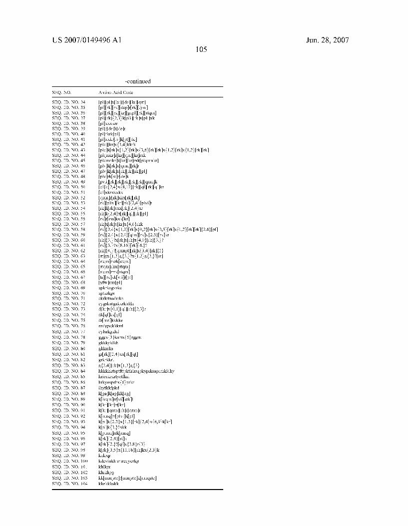


Related Documents