On-load tap-changers, type UBB User’s manual 1ZSE 5492-156 en, Rev. 4

Welcome message from author
This document is posted to help you gain knowledge. Please leave a comment to let me know what you think about it! Share it to your friends and learn new things together.
Transcript

On-load tap-changers, type UBBUser’s manual
1ZSE 5492-156 en, Rev. 4
Original instruction
The information provided in this document is intended to be general and does not cover all possible applications. Any specific application not covered should be referred directly to ABB or its authorized representative.
ABB makes no warranty or representation and assumes no liability for the accuracy of the information in this document or for the use of such information. All information in this document is subject to change without notice.
This document must not be copied without our written permission, and the contents thereof must not be imparted to a third party nor be used for any unauthorized purpose. Contravention will be prosecuted.
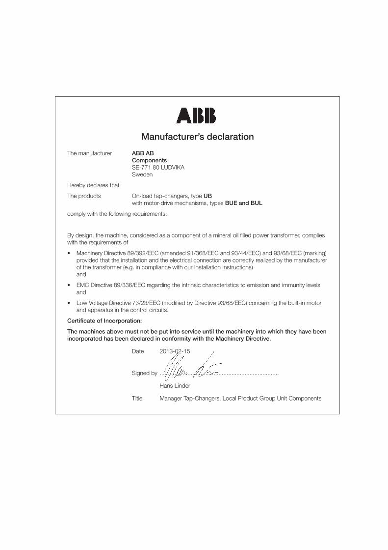
Manufacturer’s declaration
The manufacturer ABB AB Components SE-771 80 LUDVIKA Sweden
Hereby declares that
The products On-load tap-changers, type UB with motor-drive mechanisms, types BUE and BUL
comply with the following requirements:
By design, the machine, considered as a component of a mineral oil filled power transformer, complies with the requirements of
• Machinery Directive 89/392/EEC (amended 91/368/EEC and 93/44/EEC) and 93/68/EEC (marking) provided that the installation and the electrical connection are correctly realized by the manufacturer of the transformer (e.g. in compliance with our Installation Instructions) and
• EMC Directive 89/336/EEC regarding the intrinsic characteristics to emission and immunity levels and
• Low Voltage Directive 73/23/EEC (modified by Directive 93/68/EEC) concerning the built-in motor and apparatus in the control circuits.
Certificate of Incorporation:
The machines above must not be put into service until the machinery into which they have been incorporated has been declared in conformity with the Machinery Directive.
Date 2013-02-15
Signed by .........................................................................
Hans Linder
Title Manager Tap-Changers, Local Product Group Unit Components

4 User's manual UBB | 1ZSE 5492-156 en, Rev. 4
IntroductionThe UB range of on-load tap-changers manufactured by ABB has been developed over many years to provide maximum reliability. The simple and rugged design gives a service life equal to the service life of the transformer. Minimum maintenance is required for trouble-free operation. The only parts requiring maintenance are contacts that might need replacement during the service life, the insulating oil and the motor-drive mechanism.
The design allows ready access to all parts, making inspection and maintenance quick and simple.
The on-load tap-changers, type UB, is housed in the transformer tank. The motor-drive mechanism, type BUE or BUL, is attached to the transformer tank and connected to the tap-changer by means of drive-shafts and a bevel gear.
Safety warningsThe following warnings and notes are used in the manual:
WARNING
WARNING indicates an imminently hazardous situation, which if not avoided will result in death or serious injury. This signal word is to be limited to the most extreme situations.
WARNING also indicates a potentially hazardous situation, which if not avoided could result in death or serious injury.
CAUTION
CAUTION indicates a potentially hazardous situation, which if not avoided may result in minor or moderate injury. It may also be used to alert of unsafe practices.
CAUTION may also indicate property-damage-only hazards.
Safety precautions
WARNING
Personnel operating and inspecting the tap-changer must have good knowledge of the apparatus and must be aware of the risks pointed out in this manual.
Personnel making electrical connections in the motor-drive mechanism have to be certified.
WARNING
Small amounts of explosive gases might come out from the breathing devices (dehydrating breather or one-way breather). Make sure that no open fire, hot surfaces or sparks occur in the immediate surroundings of the breathing devices.
CAUTION
After a trip from a supervisory device, an inspection must be made by a specialist. The diverter switch housing must be drained and the diverter switch lifted and carefully investigated before the transformer is reenergized.
1ZSE 5492-156 en, Rev. 4 | User's manual UBB 5
Operation
WARNING
The handcrank must not be inserted during electrical operation.
WARNING
If the tap-changer is not in the exact position and the handcrank is pulled out, the motor-drive mechanism will start and go to the exact position if the power supply is on.
WARNING
If a failure in power supply occurs during operation, the operation will be completed when the power returns.
– The position indicator shows the actual tap-position.
– The draghands show the max. and min. tap-position between which the tap-changer has been working since last resetting.
– For BUE: The tap-change in progress indicator shows POSITION in service position, RAISE when operating in a raise operation and LOWER when operating in a lower operation.
– For BUL: The tap-change in progress indicator shows RED during operation and WHITE when the tap-changer is in service position.
– For resetting of the emergency stop turn the knob clockwise.
– The LOCAL/REMOTE switch. In position LOCAL the tap-changer can be operated by the RAISE/LOWER switch. In position LOCAL remote operation is rendered impossible. In position REMOTE the tap-changer is operated from the control room or by a voltage regulator. Local operation is not possible in remote position.
– In case of a failure in power supply for the motor-drive mechanism, it is possible to handcrank the tap-changer. Put the handcrank on the shaft. Make sure it has entered the slot in the shaft. Crank in the desired direction as per the information plate above the shaft. The number of turns
for one step is also shown on the rating plate. When the handcrank is inserted all electrical operations are rendered impossible. Continue cranking until the tap-changer in progress indicator shows POSITION for BUE or white colour for BUL.
– Thermostat for extra heater (option). We recommend a setting at +5 °C.
– Hygrostat for extra heater (option). We recommend a setting at approximately 60 %.
– Outlet (option) with earth fault protector.
Normally the tap-changer is controlled by a voltage regulator and no manual operation of the tap-changer and the motor-drive mechanism is needed.
Maintenance schedule
CAUTION
To maintain the high reliability of the tap-changer it is important that the inspections and the overhauls be carried out at the interval stated on the rating plate.
CAUTION
If the frequency of operations is very low and the tap-changer is filled with degassed oil after commissioning or overhaul, the gas cushion should be restored one month after filling. The absence of a gas cushion means a risk for a false trip of the pressure relay. See Restoring the gas cushion.
Maintenance of the tap-changer consists of three major steps:
– Inspection to be carried out by site personnel once a year (see below)
– Overhaul to be carried out by a specialist at intervals stated on the rating plate
– Contact replacement to be carried out by a specialist. The possible need for replacement is decided during overhaul.
A specialist is a service engineer from ABB or an authorized person trained by ABB for maintenance work on UB tap-changers.
6 User's manual UBB | 1ZSE 5492-156 en, Rev. 4
Procedure
WARNING
Checking of the breather and the oil level must be carried out from ground level since the transformer is energized.
1. Checking of the breather
WARNING
The breathers and the tube from the conservator might contain explosive gases. No open fire, hot surfaces or sparks may be present when removing the breather.
Check the breather according to the instructions for the transformer.
If more than half of the drying agent has changed colour, it must be dried or replaced.
The drying agent usually starts to change colour from the bottom of the breather. If it changes colour at the top of the breather, there is a leakage in the connections to the conservator. Locate the leakage and seal it.
2. Checking of the oil level in the conservatorThe oil level in the conservator should be according to the instructions in the transformer documentation.
3. Checking of the motor and the counterOpen the motor-drive cabinet door and turn the selector-switch to the LOCAL position. Then turn the control switch to the RAISE (LOWER) position.
Check that the motor works properly, the position indicator increases (decreases) one step, and the counter advances one step for each operation. Record the counter’s value. The counter shows the number of operations run by the tap-changer (the overhaul schedule can be determined with the help of this information).
Turn the control switch to the LOWER (RAISE) position. Check that the motor also works properly in that direction, the position indicator decreases (increases) one step and the counter advances one step more.
Reset the draghands.
Inspection
CAUTION
Approval should be given by the site engineer in charge for inspection as well as for operating the tap-changer.
It is recommended to inspect the tap-changer once a year. This principally concerns the motor-drive mechanism and refers to a visual inspection inside the BUE/BUL cabinet to check that nothing is loose, and that the heater is functioning.
In the motor-drive mechanism a counter registers every tap-change operation. During inspection the counter is read and noted. If possible, motor and counter are to be tested by operating one step and then back.
If the tap-changer has its own oil conservator, the breather and the oil level indicator on the oil conservator are to be checked according to the instructions from the transformer manufacturer.
The inspection is to be carried out while the transformer is in service.
On the conservator the following are to be checked: – Oil level – Breather
In the motor-drive mechanism the following items are to be checked: – Motor and counter – Emergency stop – Heater – Earth fault protector for the outlet (option)
If the tap-changer is equipped with an oil filter unit, the pressure drop over the filter is to be checked.
Required toolsThe following eq uipment is required for the inspection: – Set of screwdrivers – Pen and note pad
1ZSE 5492-156 en, Rev. 4 | User's manual UBB 7
7. Checking of the oil filter unit (option)If the tap-changer is equipped with an oil filter unit from ABB:
– Read the pressure gauge. – Note the reading so the change from year to year can be
seen.
If the pressure is 2.0 bar or more, or close to 2.0 bar, the filter insert should be replaced.
If moisture is suspected to have come into the tap-changer compartment, the filter insert should be replaced.
If a filter insert replacement is needed, call a specialist.
Also check for leakages. All leakages should be repaired!
Restoring the gas cushionIn case the tap changer has an oil filter unit from ABB that is installed according to our instructions, no outage of the transformer is necessary. See the manual for oil filter unit.
WARNING
Before any work is carried out on the tap-changer: Make sure that the transformer is disconnected and that earthing is properly carried out. Obtain a signed certificate from the engineer in charge.
Proceed as follows:
1. Shut the conservator valve.2. Connect a hand pump to the oil valve and start to suck
out oil. Open the air release valve to the tap-changer and let air in. Stop pumping after about 2 litres of oil have been sucked out from the tap-changer.
3. Shut the air release valve and the oil valve and disconnect the pump.
4. Open the conservator valve and an appropriate gas cushion will be formed.
4. Checking of the emergency stopGive a RAISE or LOWER impulse and after about one second press the emergency stop. The operation should be interrupted. Reset the emergency stop by turning the knob clockwise and set the protective motorswitch to ON. The started operation should now be completed. Operate back to service position.
5. Checking of the earth fault protector (option)If the motor-drive mechanism is equipped with an outlet, the earth fault protector should be tested by pressing the test knob on the outlet on BUE or on the separate earth fault protector on BUL.
6. Checking of the heater
WARNING
Before starting any work inside the motor-drive mechanism the auxiliary power must be switched off.
N. B. The motor, contactors and heating element may be energized from separate sources.
Disconnect the incoming auxiliary power.
Open the control panel (BUE only).
Check by feeling with a finger on the protection plate that the heater has been functioning.
Close the control panel (BUE only). Reconnect the incoming auxiliary power.
Complete the inspection by turning the selector-switch to the REMOTE position and closing the cabinet door.
8 User's manual UBB | 1ZSE 5492-156 en, Rev. 4
16
18
17
19
20
21
151
2
3
4
5
6
7
8
9
10
11
12 13 14
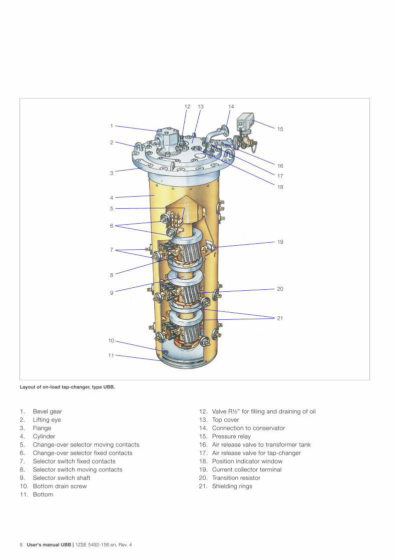
Layout of on-load tap-changer, type UBB.
1. Bevel gear2. Lifting eye3. Flange4. Cylinder5. Change-over selector moving contacts6. Change-over selector fixed contacts7. Selector switch fixed contacts8. Selector switch moving contacts9. Selector switch shaft10. Bottom drain screw11. Bottom
12. Valve R½” for filling and draining of oil13. Top cover14. Connection to conservator15. Pressure relay16. Air release valve to transformer tank17. Air release valve for tap-changer18. Position indicator window19. Current collector terminal20. Transition resistor21. Shielding rings

1ZSE 5492-156 en, Rev. 4 | User's manual UBB 9
1. Bevel gear2. Horizontal shaft with protection cover3. Vertical shaft with protection cover4. Rating plate5. On-load tap-changer6. Motor-drive mechanism
Layout of on-load tap-changer system.
2
3
4
1
1
5
6
10 User's manual UBB | 1ZSE 5492-156 en, Rev. 4
101 4 568 83 2 97 11
12
15
14 13 16
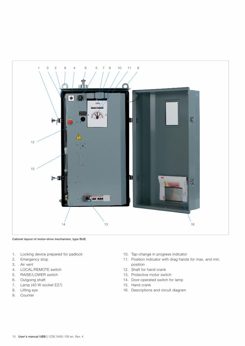
1. Locking device prepared for padlock2. Emergency stop3. Air vent4. LOCAL/REMOTE switch 5. RAISE/LOWER switch6. Outgoing shaft7. Lamp (40 W socket E27)8. Lifting eye9. Counter
10. Tap-change in progress indicator11. Position indicator with drag hands for max. and min.
position12. Shaft for hand crank13. Protective motor switch14. Door-operated switch for lamp15. Hand crank16. Descriptions and circuit diagram
Cabinet layout of motor-drive mechanism, type BUE.
1ZSE 5492-156 en, Rev. 4 | User's manual UBB 11
1
12
7
8
9
11
13
6
15
6
16
10
2 14 34 5
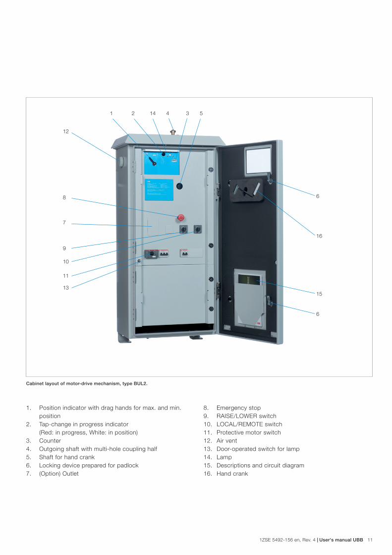
1. Position indicator with drag hands for max. and min. position
2. Tap-change in progress indicator (Red: in progress, White: in position)
3. Counter4. Outgoing shaft with multi-hole coupling half5. Shaft for hand crank6. Locking device prepared for padlock7. (Option) Outlet
8. Emergency stop9. RAISE/LOWER switch10. LOCAL/REMOTE switch 11. Protective motor switch12. Air vent13. Door-operated switch for lamp14. Lamp15. Descriptions and circuit diagram 16. Hand crank
Cabinet layout of motor-drive mechanism, type BUL2.
Contact us
© C
opyr
ight
201
3 A
BB
, A
ll rig
hts
rese
rved
.
1ZS
E 5
492-
156
en,
Rev
. 4,
201
3-04
-15ABB AB
ComponentsSE-771 80 Ludvika, Sweden Phone: +46 240 78 20 00 Fax: +46 240 121 57 E-Mail: [email protected] www.abb.com/electricalcomponents
Related Documents