Oil filter unit, type OLU, f or on-load tap-changers Manual 1ZSC000562-AAR en, Rev. 1

Welcome message from author
This document is posted to help you gain knowledge. Please leave a comment to let me know what you think about it! Share it to your friends and learn new things together.
Transcript
7/24/2019 1zsc000562-Aar en Rev 1
http://slidepdf.com/reader/full/1zsc000562-aar-en-rev-1 1/40
Oil filter unit, type OLU, foron-load tap-changersManual
1ZSC000562-AAR en, Rev. 1

7/24/2019 1zsc000562-Aar en Rev 1
http://slidepdf.com/reader/full/1zsc000562-aar-en-rev-1 2/40
Original instruction
The informat ion provided in this document is intended to be general and does not
cover all possible applications. Any specific application not covered should be
referred directly to ABB or its authorized representative.
ABB makes no warranty or representation and assumes no l iabi lity for the
accuracy of the information in this document or for the use of such information. All
information in this document is subject to change without notice.
This document must not be copied without our writ ten permission, and the contents
thereof must not be imparted to a third party nor be used for any unauthorizedpurpose. Contravention will be prosecuted.

7/24/2019 1zsc000562-Aar en Rev 1
http://slidepdf.com/reader/full/1zsc000562-aar-en-rev-1 3/40
Recommended practices
ABB recommends careful consideration of the fol lowing
factors when installing on-load tap-changers:
Before you install or commission a unit, make sure that the
personnel doing the job have read and fully understood the
installation and commissioning guide provided with the unit.
To avoid damaging the unit, never exceed the operating l imits
stated in delivery documents and on rating plates.
Do not alter or modify a unit without first consulting ABB.
Follow local and international wiring regulations at all times.
Use only factory authorized replacement parts and
procedures.
Safety warnings
The fol lowing warnings and notes are used in the manual:
WARNING
WARNING indicates an imminently hazardous
situation, which if not avoided will result in death or
serious injury. This signal word is to be limited to the
most extreme situations.
WARNING also indicates a potentially hazardous
situation, which if not avoided could result in death or
serious injury.
CAUTION
CAUTION indicates a potentially hazardous situation,which if not avoided may result in minor or moderate
injury. It may also be used to alert of unsafe practices.
CAUTION may also indicate property-damage-only
hazards.
INFO provides additional information to assist in
carrying out the work described and to provide
trouble-free operation.
Safety precautions
WARNING
Almost all types of oi l are potent ial threats to the
environment and as such they should not be drained
into ordinary sewers and "dumped" in nature. Always
check that all oil carrying components are sealed and
tight before operating the oil filter unit.
WARNING
Be aware that oil spillage on the floor around the filter
unit is a safety risk!
WARNING
Used filter elements very often contain harmful
substances separated from the oil. Always pack
and seal used elements thoroughly until they can be
disposed of in accordance with local regulations.
WARNING
Switch off the electrical power supply to the filter unit
when carrying out maintenance, and especially before
opening the terminal box of the electric motor and the
terminal box of the pressure switch.
WARNING
The oil filter unit may be hot. Be careful!
CAUTION
Do not expose the filter unit to ambient temperatureshigher than 60 °C (140 °F) as this may harm
electrical wires, hoses and other rubber or synthetic
components!
CAUTION
The fluid temperature inside the f ilter unit must never
exceed 110 °C (230 °F). Higher fluid temperatures
may cause damage to the seals and packings on and
in the filter unit.

7/24/2019 1zsc000562-Aar en Rev 1
http://slidepdf.com/reader/full/1zsc000562-aar-en-rev-1 4/40
Content
1. General information ..............................................................................................................7
1.1 Advantages with an oil lter unit ....................................................................................7
1.2 The oil lter unit .............................................................................................................7
1.2.1 Y-strainer ................................................................................................................7
1.3 Electric equipment ........................................................................................................20
1.4 Oil lter circuit ...............................................................................................................20
1.5 Continuous oil ltration ..................................................................................................21
1.6 Filtration medium ..........................................................................................................21
1.7 Service temperature ......................................................................................................22
1.8 Filter cartridge replacement interval ...............................................................................221.9 Leakage in the oil lter unit circuit ..................................................................................22
1.10 Oil level in the on-load tap-changer .............................................................................22
1.11 Ordering data ..............................................................................................................22
1.12 Spare parts .................................................................................................................22
1.13 Technical specications ..............................................................................................23
1.13.1 Technical specication for common parts of an oil lter unit ..................................23
1.13.2 Motor specication for oil lter unit with 1 cartridge type OLU1C50NV ..................23
1.13.3 Motor specication for oil lter unit with 2 cartridges type OLU1D50NV ................24
1.13.4 Motor specication for oil lter unit with 4 cartridges type OLU2D50NV ................24
2 Installation .............................................................................................................................25
2.1 General .........................................................................................................................252.2 Tools .............................................................................................................................25
2.3 Material .........................................................................................................................25
2.4 Weight ..........................................................................................................................25
2.5 Receiving ......................................................................................................................25
2.5.1 Unpacking ..............................................................................................................25
2.5.2 Inspection on receipt ..............................................................................................25
2.5.3 Temporary storage before assembly .......................................................................25
2.6 Mounting ......................................................................................................................25
2.6.1 Plumbing ................................................................................................................25
2.6.2 Electrical connection ...............................................................................................26
3 Commissioning ......................................................................................................................27
4 Transportation .......................................................................................................................28
5 Maintenance ..........................................................................................................................29
5.1 Tools .............................................................................................................................29
5.2 Material .........................................................................................................................29
5.3 Annual inspection .........................................................................................................29
5.4 Maintenance .................................................................................................................29
5.5 Filter cartridge replacement ...........................................................................................29

7/24/2019 1zsc000562-Aar en Rev 1
http://slidepdf.com/reader/full/1zsc000562-aar-en-rev-1 5/40
6 Repair....................................................................................................................................33
6.1 Replacement of pump/motor unit .................................................................................33
6.1.1 Tools ......................................................................................................................33
6.1.2 Material ..................................................................................................................33
6.1.3 Dismounting ...........................................................................................................33
6.1.4 Remounting ............................................................................................................33
6.1.5 Filling up small amount of oil in the oil conservator ..................................................34
7 Spare parts list ......................................................................................................................35
7.1 Introduction ..................................................................................................................35
7.2 Oil lter unit serial number .............................................................................................35
7.3 Item number .................................................................................................................357.4 Name of item ................................................................................................................35
7.5 Quantity ........................................................................................................................35
7.6 Remarks .......................................................................................................................35
7.7 General arrangement ....................................................................................................35
7.8 Standard spare parts ....................................................................................................35
7.9 Special spare parts .......................................................................................................35
7.10 Spare parts list for oil lter unit ....................................................................................35
8 Recycling ...............................................................................................................................36
8.1 Introduction ..................................................................................................................36
8.2 Recycling of packaging material ....................................................................................36
8.3 Scrapping and destruction ............................................................................................368.4 Approximate material content .......................................................................................36
8.5 Hazardous waste ..........................................................................................................36

7/24/2019 1zsc000562-Aar en Rev 1
http://slidepdf.com/reader/full/1zsc000562-aar-en-rev-1 6/40

7/24/2019 1zsc000562-Aar en Rev 1
http://slidepdf.com/reader/full/1zsc000562-aar-en-rev-1 7/401ZSC000562-AAR en, Rev. 1 | Oil filter unit OLU 7
1. General information
This manual g ives informat ion for one oil filter unit. In case of
two or more units on the same transformer, all procedures are
the same for each one of the units.
1.1 Advantages with an oil filter unit
All on-load tap-changers manufactured by ABB are designed
and tested for service in transformer oil without any kind
of filtration. Filtration of oil is necessary only when normal
maintenance is carried out.
However, filtering gives the following advantages:
Dielectric strength in the oil is maintained high, important in
line end applications.
Eliminates risk for depositing “sludge” in electrically highly
stressed areas.
Filtration reduces mechanical wear, which is beneficial in
applications with high operation frequency.
It simplifies maintenance since no cleaning and no further
oil filtration is necessary. This is also important from a health
point of view for the service staff and it also shortens thetransformer outage time.
1.2 The oil filter unit
See Fig. 1.
The oil filter unit and the filter cartr idge are del ivered by ABB.
The on-load tap-changer is also prepared for connection to
the oil filter unit.
The oil filter unit allows continuous serv ice of the t ransformer
during filtration.
The filter unit cons ists of a fi lter base, one or two filter
housings, an electric motor, a pump, an electric connection
box, a sample valve and two threaded connections.
There is also a pressure switch that could be used by the
customer. The switch changes state when the pressure in the
filter is such that a filter cartridge replacement is necessary.
This switch does not stop the motor, it only gives information
about the filter status.
A f low switch is mounted at the oil filter unit outlet. The
switch changes state when the oil flow through the filter unit
is approximately half of the nominal oil flow. This switch does
not stop the motor, it only tells if there is an oil flow or not.
The motor/pump unit is a sealed unit and must not be
disassembled. It is mounted on the filter house. The oil pump
is a screw type pump.
The filter cartr idge is del ivered separately and i t must be
mounted in the filter housing by the customer before starting
the oil filter unit.
There is also a pressure gauge which measures the pressure
in the oil filter. At a certain pressure level, a filter cartridge
replacement is necessary.
Each of the filter housings contains a lid with O-ring sealing.
The oil inlet connection is placed at the o il stra iner.
The oil outlet connection is the port at the o il f low switch
placed at the bottom of the filter housing.
The tubes for connection between the oil filter unit and the
on-load tap-changer are not included in the delivery of the oil
filter unit.
1.2.1 Y-strainer
See Fig. 1.
The oil pump in the f ilte r un it will be damaged if big particles
(such as welding sparks, dirt from grinding processes or
sealing agent) are allowed to enter the pump. To prevent that,
a strainer (pos. 26) with a mesh width of 0.5 mm is delivered
with the oil filter unit. This strainer is mounted at the inlet portof the oil pump.
When the oil filter unit has been running for a while, e.g.
two months, the strainer must be cleaned from particles.
The cleaning should be repeated at every exchange of f ilter
cartridge, or if, for some reason the oil pipes have been
dismantled.

7/24/2019 1zsc000562-Aar en Rev 1
http://slidepdf.com/reader/full/1zsc000562-aar-en-rev-1 8/408 Oil filter unit OLU | 1ZSC000562-AAR en, Rev. 1
Fig. 1. Oil filter unit OLU1C.
1. Auxiliary switch
2. Motor protective
switch
3. Pressure switch
4, 5. Pump/motor unit
6. Pressure gauge
7. Filtration element
9. Shunt release
20. Filter housing21. Connection box
24. Drain plug
25. Lid
26. Y-strainer
27. Flow switch
28. Air vent and oil
sample point, dirty oil
29. Wall bracket
Oil inlet G ¾” male acc. to ISO 228-1
Coupling part for exible hose mounted.
Cable glands
2 pcs. M20 cable 8-13 mm4 pcs. M16 cable 5-9 mm
Oil outlet G ¾” male acc. to ISO 228-1
Coupling part for exible hose mounted.

7/24/2019 1zsc000562-Aar en Rev 1
http://slidepdf.com/reader/full/1zsc000562-aar-en-rev-1 9/401ZSC000562-AAR en, Rev. 1 | Oil filter unit OLU 9
Fig. 2. Oil filter unit OLU1C.
Free space for exchange of ltration element
N.B. 2 pcs of exible PTFE-hose with angefor O-ring sealing delivered with the oil lterand must be mounted by the customer,
according to the included instructions.

7/24/2019 1zsc000562-Aar en Rev 1
http://slidepdf.com/reader/full/1zsc000562-aar-en-rev-1 10/4010 Oil filter unit OLU | 1ZSC000562-AAR en, Rev. 1
Fig. 3. Oil filter unit OLU1D.
Oil inlet G ¾” male acc. to ISO 228-1
Coupling part for exible hose mounted.
Oil outlet G ¾” male acc. to ISO 228-1
Coupling part for exible hose mounted.
1. Auxiliary switch
2. Motor protective switch
3. Pressure switch
4, 5. Pump/motor unit6. Pressure gauge
7. Filtration element
9. Shunt release
20. Filter housing
21. Connection box
24. Drain plug
25. Lid
26. Y-strainer
27. Flow switch
28. Air vent and oil sample
point, dirty oil
29. Wall bracket
Cable glands
2 pcs. M20 cable 8-13 mm
4 pcs. M16 cable 5-9 mm

7/24/2019 1zsc000562-Aar en Rev 1
http://slidepdf.com/reader/full/1zsc000562-aar-en-rev-1 11/401ZSC000562-AAR en, Rev. 1 | Oil filter unit OLU 11
Fig. 4. Oil filter unit OLU1D.
N.B. 2 pcs of exible PTFE-hose with angefor O-ring sealing delivered with the oil lter
and must be mounted by the customer,according to the included instructions.
Free space for exchange of ltration element

7/24/2019 1zsc000562-Aar en Rev 1
http://slidepdf.com/reader/full/1zsc000562-aar-en-rev-1 12/4012 Oil filter unit OLU | 1ZSC000562-AAR en, Rev. 1
5 0 0
( 1 5 7 5 )
660
7 20
628
25
1 2 9 21
3
26
27
4 5
29
24
Fig. 5. Oil filter unit OLU2D.
Oil inlet G ¾” male acc. to ISO 228-1
Coupling part for exible hose mounted.
Oil outlet G ¾” male acc. to ISO 228-1
Coupling part for exible hose mounted.
1. Auxiliary switch
2. Motor protective
switch
3. Pressure switch
4, 5. Pump/motor unit
6. Pressure gauge
7. Filtration element
9. Shunt release
20. Filter housing
21. Connection box24. Drain plug
25. Lid
26. Y-strainer
27. Flow switch
28. Air vent and oil
sample point, dirty
oil
29. Wall bracket
Cable glands
2 pcs. M20 cable 8-13 mm
4 pcs. M16 cable 5-9 mm

7/24/2019 1zsc000562-Aar en Rev 1
http://slidepdf.com/reader/full/1zsc000562-aar-en-rev-1 13/401ZSC000562-AAR en, Rev. 1 | Oil filter unit OLU 13
5 0
5 0
4 5 0
4 3 0
5 6 5
5 8 2
305 305
165
195
165
385
11
R 5 ,5 3 0 0
( 7 5 0 )
5
9 5
A
A
Fig. 6. Oil filter unit OLU2D.
N.B. 2 pcs of exible PTFE-hose with angefor O-ring sealing delivered with the oil lterand must be mounted by the customer,
according to the included instructions.
Free space for exchange of ltration element

7/24/2019 1zsc000562-Aar en Rev 1
http://slidepdf.com/reader/full/1zsc000562-aar-en-rev-1 14/4014 Oil filter unit OLU | 1ZSC000562-AAR en, Rev. 1
Fig. 7. Flexible PTFE hose with O-ring sealed flange
Total length 335
Delivered unmounted
Min. bend radius 135 mm
Flexible hose of PTFE ½” with one braided
layer of stainless steel wire
Min. bend radius 135 mm
Temp. range: -50 °C to +150 °C
7/24/2019 1zsc000562-Aar en Rev 1
http://slidepdf.com/reader/full/1zsc000562-aar-en-rev-1 15/401ZSC000562-AAR en, Rev. 1 | Oil filter unit OLU 15
P >Q>
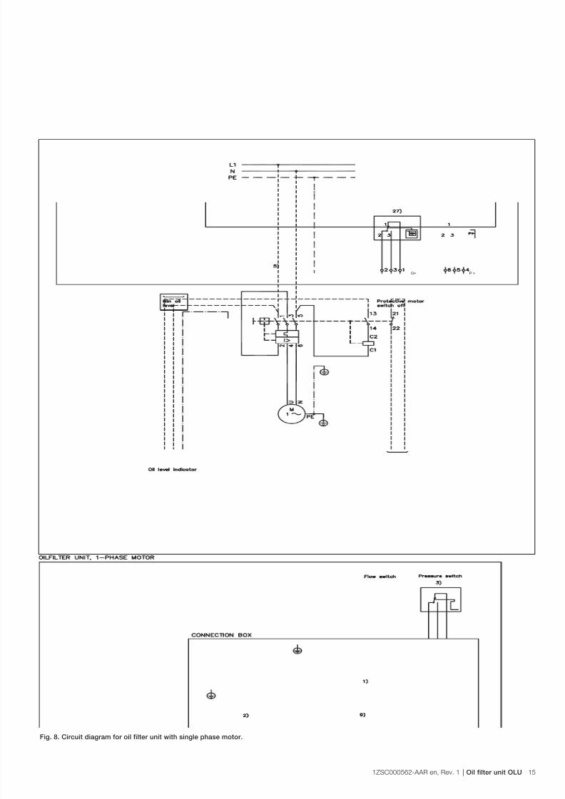
Fig. 8. Circuit diagram for oil filter unit with single phase motor.
1) Auxiliary switch
2) Protective motor switch
3) Pressure switch
5) Motor
9) Shunt release
27) Flow switch

7/24/2019 1zsc000562-Aar en Rev 1
http://slidepdf.com/reader/full/1zsc000562-aar-en-rev-1 16/4016 Oil filter unit OLU | 1ZSC000562-AAR en, Rev. 1
P >Q>
1) Auxiliary switch
2) Protective motor switch
3) Pressure switch
5) Motor
9) Shunt release
27) Flow switch
Fig. 9. Circuit diagram for oil filter unit with 3-phase motor.

7/24/2019 1zsc000562-Aar en Rev 1
http://slidepdf.com/reader/full/1zsc000562-aar-en-rev-1 17/401ZSC000562-AAR en, Rev. 1 | Oil filter unit OLU 17
Fig. 10. On-load tap-changer type UC with oil filter unit.
View show UCC/UCD
Tube from oil lter outlet, min ½”
Tube to oil lter inlet, min ½”
Oil lter outlet tube, min ½”
Valve
From lter To lter
Valve
View show UCG View show UCL

7/24/2019 1zsc000562-Aar en Rev 1
http://slidepdf.com/reader/full/1zsc000562-aar-en-rev-1 18/4018 Oil filter unit OLU | 1ZSC000562-AAR en, Rev. 1
Fig. 11. On-load tap-changer type UC with oil filter unit.
View show UCC/UCD
Tube from oil lter outlet, min ½”
Tube to oil lter inlet, min ½”
Oil lter outlet tube, min ½”
Valve
From lter To lter
Valve
View show UCG View show UCL

7/24/2019 1zsc000562-Aar en Rev 1
http://slidepdf.com/reader/full/1zsc000562-aar-en-rev-1 19/401ZSC000562-AAR en, Rev. 1 | Oil filter unit OLU 19
Fig. 13. On-load tap-changer type UBB with oil filter unit.
Fig. 12. On-load tap-changer type UZ with oil filter unit.
Tube from oil lter outlet, min ½”
Tube from oil lter outlet, min ½”
Tube to oil lter inlet, min ½”
Tube to oil lter inlet, min ½”
Oil lter outlet tube, min ½”
Oil lter outlet tube, min ½”
Valve
Valve
Valve

7/24/2019 1zsc000562-Aar en Rev 1
http://slidepdf.com/reader/full/1zsc000562-aar-en-rev-1 20/4020 Oil filter unit OLU | 1ZSC000562-AAR en, Rev. 1
1.3 Electric equipment
See Figs. 8 and 9.
All motor control equipments are installed in a connection
box.
The oil filter unit needs an electr ic power supply to the
motor. This power supply should be connected to the motor
protective switch in the connection box.
The pressure switch has three electric connections. The signal
from this switch is recommended to be used in a control roomas an indication for the need of filter cartridge replacement.
The flow switch has three electric connections. The signal
from this switch is recommended to be used in a control
room as an indication that the motor/pump unit is pumping
sufficient of oil in the right direction.
It is recommended to connect the “low level contact” signal
from the oil level indicator on the conservator, so it trips the
motor protective switch by the trip coil in case of low oil level
in the conservator due to leakage in the oil filter circuit or
some other cause.
The motor protective switch has a status indication contact
which shows if the motor circuit breaker is off or on. This
contact is recommended to be connected in a way that
makes a trip immediately visible in the control room.
Since the oil filter is working continuously, no other electrical
components are necessary.
1.4 Oil filter circuit
See Figs. 10-13.
In the oil filter inlet port and outlet port respectively, there is
mounted one half of a swivelling fitting for the supplied flexible
PTFE hose. The PTFE hose must be used for connecting
the oil filter unit to the pipe system. It is essential to do so to
reduce noise and vibrations and also to avoid excess forces
from the pipe system. It is not allowed to connect the pipe
system directly to the oil filter ports, without using the flexible
PTFE hose.
The oil fil ter unit should be placed lower than the return
connection of the on-load tap-changer.
The oil fil tering circuit is near ly the same for all different types
of ABB on-load tap-changers. The only difference is the
connection to the on-load tap-changers. The oil filter unit
inlet tube is connected to the UC and UZ types of on-load
tap-changers by flanges on the oil valves. On UB type of on-
load tap-changers, the oil filter unit inlet tube is connected
to a flange on a tube in the centre of the cover. No valve is
mounted.
All flanges for the oil filter unit inle t tube have dimensions
according to Figs. 14 and 15.
The oil fil ter unit inlet tube shal l have a valve near the o il f ilter
unit to make it possible to shut off the oil flow in case of filter
cartridge replacement, repair work, etc.
The oil fil ter unit outlet tube for the UB and UC types of
on-load tap-changers shall be connected to the free flange
on the head of the on-load tap-changer. Dimensions are
according to Fig. 14. The position of this free flange may vary,
depending on where the pressure relay and the tube to theconservator are connected.

7/24/2019 1zsc000562-Aar en Rev 1
http://slidepdf.com/reader/full/1zsc000562-aar-en-rev-1 21/401ZSC000562-AAR en, Rev. 1 | Oil filter unit OLU 21
WARNING
Make sure that the oil filter unit outlet tube is not
connected to the OLTC transformer main tank flange.
The oil filter unit outlet tube for the UZ type of on-load tap-
changers is connected to a flange on the top of the UZ-tank,
see Fig. 12. This flange has dimensions according to Fig. 15.
The exact posit ion is shown on the dimension drawing for the
on-load tap-changer.
The oil filter unit outlet tube shall have a va lve near the oil filterunit to make it possible to shut off the oil flow in case of filter
cartridge replacement, repair work, etc.
It is recommended to install a valve in a T-piece in the inlet
pipe close to the Y-strainer, see Fig. 10.
This valve may be used for draining or f illing the conservator.
1.5 Continuous oil filtration
The oil filter unit is work ing according to the continuous
operation principle. Thus the filtration runs continuously with a
low and smooth flow rate, giving the best filtration result.
This gives a number of advantages:
– Narrower pipes might be used.
– No change in flow rate eliminates release of already
trapped particles.
– Reduced risk of foam or gas bubbles.
– Moisture removal works even if the on-load tap-changer is
not operating. – This method requires very little control equipment. The
necessary components are placed in the electric control
box.
– Maximum power needed is approximately 370 W per unit.
The average power consumpt ion during a li fe cycle of the
oil filter unit is considerably lower.
1.6 Filtration medium
The oil filter unit should only be used for filtering t ransformer
oil according to IEC 60296. For other media, please consult
ABB.
Fig. 14. Flange on on-load tap-changers type UBB and UC. Fig. 15. Flange on on-load tap-changers type UZ.
130
100
75
M12
52a= 18-25 mm
75
100
55
M10

7/24/2019 1zsc000562-Aar en Rev 1
http://slidepdf.com/reader/full/1zsc000562-aar-en-rev-1 22/4022 Oil filter unit OLU | 1ZSC000562-AAR en, Rev. 1
1.7 Service temperature
The ambient temperature may vary between -40˚ C to +60˚ C
(-40˚ F to +140˚ F)
Normal operating range for the filtrated oil is from 0˚ C to
+100˚ C (+32˚ F to 212˚ F)
An oil filter unit with a new filter cartr idge can be started
with an oil temperature down to -25˚ C (-13˚ F) provided the
viscosity is 1000 cSt or lower.
If the filter cartridge has been in service for a while and apressure drop has been built up, the pressure switch may
give alarm when starting at low oil temperatures. This can
be avoided by letting the transformer oil be warmed up to at
least 0˚ C (32˚ F) before the oil filter unit is switched on. The
pressure switch will give signal until the warm oil from the on-
load tap-changer has come into the oil filter unit.
If the pressure switch is still giving signal after half an hour,
wait until the transformer oil has become even warmer and
then start again.
If the transformer is subjected to many starts in very lowtemperature (e.g. spare transformers), make sure that the filter
cartridge is changed frequently.
If the service conditions are such that the ambient
temperature is very low (often and during long periods below
-10˚ C (-14˚ F), the oil temperature of the transformer is low
and the inlet tube is long (>3m), the oil filter unit inlet tube
should be heat insulated.
1.8 Filter cartridge replacement interval
See section 5.2 Maintenance.
1.9 Leakage in the oil filter unit circuit
There is always a risk of leakage in an oi l ci rcuit , wi th a too
low oil level in the on-load tap-changer housing as a result.
This risk can be reduced by using an o il level indicator, with
alarm contacts for low level, on the conservator. The signal
should be used to give an alarm in the control room, and
to trip the motor protective switch of the oil filter unit, by
activating the shunt release coil. See the wiring diagrams in
Figs. 8 and 9.
1.10 Oil level in the on-load tap-changer
When filling oil into an on-load tap-changer with an oil
filter unit, fill oil in excess into the conservator to avoid
refilling afterwards!
– Approx. 20 liters for oil filter unit with 1 filter cartridge.
– Approx. 40 liters for oil filter unit with 2 filter cartridges.
– Approx. 80 liters for oil filter unit with 4 filter cartridges.
1.11 Ordering data
When ordering an oil filter unit the following must be given:
– The motor voltage – The voltage for the trip coil of the motor circuit breaker.
1.12 Spare parts
Avoid order ing spare fi lter cartridges unti l they are
needed. They can not be stored for more than 24
months without reduced water removing capacity. See
also chapter 7.

7/24/2019 1zsc000562-Aar en Rev 1
http://slidepdf.com/reader/full/1zsc000562-aar-en-rev-1 23/401ZSC000562-AAR en, Rev. 1 | Oil filter unit OLU 23
1.13 Technical specifications
1.13.1 Technical specification for common parts of an oil
filter unit
Oil pump Settima screw pump
Flow rate: 250-300 l/h (67-80 gph)
Over-pressure valve: Opening pressure 5.0 bar
Filter cartridge: Type: 50 NVD
Material: Cellulose
Specially dried for water absorption
Filtering grade: 3 µm absolute
Typically pressure drop at 20 °C temperature andnew filter cartridge: <0.1 bar
Max. storage time: 24 months, with undamaged
package.
Pressure switch: GEMS PS41
Adjusted value: 4 bar
Max. voltage: 230 V AC, 24 V DC
Contact rat ing: Max. cur ren t: Res. load 5 A
Ind. load 3 A at 28 V
Protection class: IP67 with 2 meter flying lead
Flow switch: DKM-1
Adjusted value: Approximately 125 l/h (33 gph)
Contact rating Max. load 250 V, 1.5 A 50 VA (min. load 3 VA)Reed contacts are very sensitive to overload and
must be protected against inductive, capacitive or
resistive overload.
A common way to protect is to use a RC-ci rcuit .
Protection class: IP67 with 2 meter flying lead
Electric connection
box:
2 cable glands M20, cable diameter 8-13 mm
4 cable glands M16, cable diameter 5-9 mm
Max. 2 x 2.5 mm2 wire on each terminal.
Noise: <70 dB (A) acc. to ISO 4412
Connecting tubes: Min. ½“
Connections for oil: Male G ¾ “ acc. to ISO 228-1
Material: Stainless steel, painted carbon steel.
Colour: RAL 7032
1.13.2 Motor specification for oil filter unit with 1 cartridge
type OLU1C50NV
Motor ABB article number for a
complete oil filter unit with
motor
Type: 1-phase, squir rel-cage
Data: 110 V/0.37 kW, 50/60 Hz
Speed: 1370-1660 rpm
Protection class: IP55
1ZSC003676-AAA
Type: 1-phase, squir rel-cage
Data: 230 V/0.37 kW, 50/60 HzSpeed: 1370-1660 rpm
Protection class: IP55
1ZSC003676-AAB
Type: 3-phase, squir rel-cage
Data: 500 V/0.37 kW, 50/60 Hz
Speed: 1370-1660 rpm
Protection class: IP55
1ZSC003676-AAC
Type: 3-phase, squir rel-cage
Data: 208-277 V/0.37 kW, 50/60 Hz
Speed: 1370-1660 rpm
Protection class: IP55
1ZSC003676-AAD
Type: 3-phase, squir rel-cage
Data: 360-480 V/0.37 kW, 50/60 HzSpeed: 1370-1660 rpm
Protection class: IP55
1ZSC003676-AAE

7/24/2019 1zsc000562-Aar en Rev 1
http://slidepdf.com/reader/full/1zsc000562-aar-en-rev-1 24/4024 Oil filter unit OLU | 1ZSC000562-AAR en, Rev. 1
1.13.3 Motor specification for oil filter unit with 2
cartridges type OLU1D50NV
Motor ABB article number for a
complete oil filter unit with
motor
Type: 1-phase, squir rel-cage
Data: 110 V/0.37 kW, 50/60 Hz
Speed: 1370-1660 rpm
Protection class: IP55
1ZSC003676-AAF
Type: 1-phase, squir rel-cage
Data: 230 V/0.37 kW, 50/60 HzSpeed: 1370-1660 rpm
Protection class: IP55
1ZSC003676-AAG
Type: 3-phase, squir rel-cage
Data: 500 V/0.37 kW, 50/60 Hz
Speed: 1370-1660 rpm
Protection class: IP55
1ZSC003676-AAH
Type: 3-phase, squir rel-cage
Data: 208-277 V/0.37 kW, 50/60 Hz
Speed: 1370-1660 rpm
Protection class: IP55
1ZSC003676-AAJ
Type: 3-phase, squir rel-cage
Data: 360-480 V/0.37 kW, 50/60 HzSpeed: 1370-1660 rpm
Protection class: IP55
1ZSC003676-AAK
1.13.4 Motor specification for oil filter unit with 4
cartridges type OLU2D50NV
Motor ABB article number for a
complete oil filter unit with
motor
Type: 1-phase, squir rel-cage
Data: 110 V/0.37 kW, 50/60 Hz
Speed: 1370-1660 rpm
Protection class: IP55
1ZSC003676-AAL
Type: 1-phase, squir rel-cage
Data: 230 V/0.37 kW, 50/60 HzSpeed: 1370-1660 rpm
Protection class: IP55
1ZSC003676-AAM
Type: 3-phase, squir rel-cage
Data: 500 V/0.37 kW, 50/60 Hz
Speed: 1370-1660 rpm
Protection class: IP55
1ZSC003676-AAN
Type: 3-phase, squir rel-cage
Data: 208-277 V/0.37 kW, 50/60 Hz
Speed: 1370-1660 rpm
Protection class: IP55
1ZSC003676-AAP
Type: 3-phase, squir rel-cage
Data: 360-480 V/0.37 kW, 50/60 HzSpeed: 1370-1660 rpm
Protection class: IP55
1ZSC003676-AAR

7/24/2019 1zsc000562-Aar en Rev 1
http://slidepdf.com/reader/full/1zsc000562-aar-en-rev-1 25/401ZSC000562-AAR en, Rev. 1 | Oil filter unit OLU 25
2 Installation
2.1 General
The oil filter unit should be mounted at ground level to enable
maintenance and repair work without de-energizing the
transformer and to avoid gas collection.
Figs. 10-13 shows the valves that are recommended to use in
the oil circuit.
A special bracket p late has to be placed on the t ransformer.
Dimensions for fixing screw joints, se Fig. 2.
For the UC-types of on-load tap-changers up to three unitsshould be mounted one for each of on-load tap-changer.
2.2 Tools
– Normal set of hand tools
– Small pipe wrench
2.3 Material
– A bucket, oil resistant
– Cleaning paper
– Lubrication for stainless steel connections
2.4 Weight – Approximately 40 kg for oil filter unit with 1 filter cartridge
(OLU1C)
– Approximately 80 kg for oil filter unit with 2 filter cartridges
(OLU1D)
– Approximately 160 kg for oil filter unit with 4 filter cartridges
(OLU2D)
2.5 Receiving
2.5.1 Unpacking
Check that the package is undamaged.
Normally the filter units are delivered in boxes of plywood. Therefore only the assembly screws should be removed.
Lifting of the box should be carried out with a lifting device.
Avoid manually heavy l ifting.
2.5.2 Inspection on receipt
Check that the oil filter unit, the pressure gauge, the pressure
switch, the flow switch and the Y-strainer are undamaged.
If transport damage is found, and it is judged that correct
operation of the oil filter unit is not possible, a damage
report should be sent to the insurance company. It is alsorecommended that photographs are taken of the damaged
details. Mark the photos with ABB’s reference number and the
serial number of the oil filter unit, and send them to ABB for
comments.
2.5.3 Temporary storage before assembly
If the oil filter unit is not to be assembled immediately once
the delivery has been approved, keep the oil filter unit and the
filter cartridge in the delivery package.
CAUTION
The package of the filter cartr idge must not be
opened! The special package ensures maintained
water absorption capacity of the filter cartridge.
2.6 Mounting
Mounting may be carried out after mounting of the on-load
tap-changer in the transformer factory or at commissioning on
site.
A c learance of 500 mm is necessary above the f ilter housing
to enable exchange of filter cartridges. The filter unit should
be mounted on a vibration free surface. In case of vibrations,
vibration absorbing rubber feet should be used. The pressure
gauge should be visible and easy to read. The sample valves
should be easily accessible.
2.6.1 Plumbing
CAUTION
Do not open the filter cartridge package at this stage
Plumbing is recommended to be carried out after oil
filling of the on-load tap-changer.
Start by mounting the oil filter unit to a bracket plate on the
transformer. Manufacture an inlet tube and an outlet tube
as recommended in Figs. 10-13, depending on which typeof on-load tap-changer the filter unit is to be connected to.
For dimensions of connecting flanges, see section 1.4 or the
dimension drawing delivered with the on-load tap-changer.
CAUTION
Remove the plastic plugs from the inlet and outlet
connections before installation.
Make sure that the tubes are clean before connection to the
on-load tap-changer.
Make sure that all O-rings are in place before connecting the
flanges.

7/24/2019 1zsc000562-Aar en Rev 1
http://slidepdf.com/reader/full/1zsc000562-aar-en-rev-1 26/4026 Oil filter unit OLU | 1ZSC000562-AAR en, Rev. 1
WARNING
Do not mix up inlet and outlet ports on oil filter unit or
on the on-load tap-changer. The filtration will be poor,
and in worst case, a flashover may occur in the on-
load tap-changer.
The connection points are shown in F igs. 10-13.
UCG and UCL have vertical flanges instead of horizontal as
shown in Fig. 11 (UCC).
Connect the inlet tube to the valve with flange.
The outlet tube from the oil filter unit is connected to any
one of the free flanges, except to the one connected to the
transformer tank.
For UBB on-load tap-changers there is a flange connection
without a valve in the centre of the cover.
On UZ-type of on-load tap-changers there is a special
flange for oil filter unit outlet tube, se the dimension drawing
delivered together with the on-load tap-changer or Fig. 12 inthis manual.
Try to keep the tubes short and with as few joints and bends
as possible. If the tubes are longer than 5 meters, increase
the tube diameter to 3/4 “.
When the transformer will be operating on sites where
the temperature frequently falls below -10˚ C (+14˚ F), it is
recommended to heat insulate the inlet tube.
When the oil filter unit has been running for a while, e.g.
two months, the Y-strainer must be cleaned from particles. The cleaning should be repeated at every exchange of f ilte r
cartridge, or if, for some reason the oil pipes have been
dismantled.
2.6.2 Electrical connection
WARNING
Make sure that the voltage is properly switched off
before starting wiring work!
Only qualified personnel should attempt installation of
electrical equipment.
Make sure that the available voltage and frequency is in
accordance with the rating of the electric motor.
Connect the motor supply to the electric connection box as
shown in the wiring diagram in Figs. 8 and 9 in this manual.
The pressure switch and the flow switch should be connected
to give information to the control room if pressure is over its
limit or if oil flow is below its limit.
It is also recommended to use an oil level indicator with a
contact for low oil level in the conservator, and to connect it
so a trip from that contact will switch off the motor protective
switch to the oil filter unit, and to give an alarm in the controlroom. See the wiring diagrams in Figs. 8 and 9.
Make sure that the motor has correct rotation direction by
comparing the rotation of the fan with the arrow on the motor.
WARNING
If the rotation direction is wrong, the cleaning of the
oil will be poor, and in worst case, a flashover may
occur in the on-load tap-changer.

7/24/2019 1zsc000562-Aar en Rev 1
http://slidepdf.com/reader/full/1zsc000562-aar-en-rev-1 27/401ZSC000562-AAR en, Rev. 1 | Oil filter unit OLU 27
3 Commissioning
Make sure that all valves are closed. See Figs. 10-13.
Do not break the sealed package of the new filter
cartridges until immediately before installation.
1. Dismantle the filter housing lid (item 25) by loosening the 6
nuts. (See Fig. 19.)
2. Dismantle the filter cartridge assembly bolt with seal,
spring and washers. (See Fig. 20.)
3. Inspect the O-ring at filter housing and replace it if
necessary. (See Fig. 23.)4. Take the new filter element out of the plastic bag. Check
“use by date”. Throw the plastic bag, together with the
silica gel in a dedicated place. (See Fig. 24.)
Remove the package of silica gel from the new filter
cartridges before installation.
5. Check that an O-ring is fitted to the base of filter cartridge.
(See Fig. 25.)
6. Place the new filter cartridge on to the filter housing center
pipe and carefully lower the cartridge into the filter housing
(item 20). (See Fig. 26.)7. Remount the filter cartridge assembly bolt with seal, spring
and washers, max. torque 15 Nm. (See Fig. 27.)
8. Remount the filter housing lid (item 25) and tighten the 6
nuts, max. torque 15 Nm. (See Figs. 29 and 30.)
9. For mounting of filter cartridges in the second filter
housing, repeat step 1 – 8.
10. Open the inlet and outlet valves.
11. Open the air vent valve, and the plug on the second filter
housing (item 28) and remove all air from the filter housing,
close valve and plug when no more air comes out.
12. Fill up conservator with oil if necessary.
13. Start the filter unit.14. Check that no leaks have occurred.

7/24/2019 1zsc000562-Aar en Rev 1
http://slidepdf.com/reader/full/1zsc000562-aar-en-rev-1 28/4028 Oil filter unit OLU | 1ZSC000562-AAR en, Rev. 1
4 Transportation
The oil filter unit may be t ransported mounted on the
transformer, provided that it is properly fixed.
If the unit should be dismounted before transportation,
proceed as follows:
Prepare the on-load tap-changer as stated in the applicable
guide.
If the oil filter unit has been oil filled, drain as follows:
Shut all valves. Drain all oil from the filter housing. (item 20). The bucket may be empt ied several times before the draining
is completed.
Dismount the tubes. Keep the O-rings, the screws, nuts and
the washers.
CAUTION
Oil will pour out from the tubes when they are
loosened. Prepare for taking care of that oil!
The seal ing in the f lange of the on-load tap-changer
work with “rubber excess” which makes the O-rings
looking somewhat damaged, but they can be reused
provided that they are left in their positions or refitted
in the same positions as they had earlier.
Mount the covers on the return flange of the on-load tap-
changers. Mount a cover on the flange for the inlet tube on
the UB on-load tap-changer.
Remove all wirings.
WARNING
Make sure that the voltage is properly switched off
before starting wiring work!
The oil fil ter unit is t ransported in i ts delivery package which
can be reused.
Remounting at site is done by using appropriate parts
according to section 2.6.
Restart the oil filter unit by using appropriate parts according
to section 3.

7/24/2019 1zsc000562-Aar en Rev 1
http://slidepdf.com/reader/full/1zsc000562-aar-en-rev-1 29/401ZSC000562-AAR en, Rev. 1 | Oil filter unit OLU 29
5 Maintenance
The oil filter unit is maintained during the annual inspection of
the on-load tap-changer and during the normal maintenance
of the on-load tap-changer.
The maintenance needed is replacement of the o il f ilter
cartridge when necessary and to clean the strainer.
The cleaning should be repeated at every exchange of o il
filter cartridge, or if, for some reason the oil pipes have been
dismantled.
When a new oil filter unit has been running for a while, e.g.two months, the strainer must be cleaned from particles.
During the annual inspection of the on-load tap-changer,
check for abnormal noise, heat or vibrations from the oil filter
motor/pump unit.
Also check that the oil flow switch does not give an alarm
signal.
The motor and pump is a sealed unit and must be replaced as
one unit.
5.1 Tools
– Normal set of hand tools
– Bucket (oil resistant)
5.2 Material
– Spare filter cartridge
– For ordering, see chapter 7 Spare parts list
5.3 Annual inspection
– During the annual inspection of the on-load tap-changer,
the pressure gauge is read. Note the reading so the change
from year to year can be seen. – If the pressure is close to 4 bar or more, the filter cartridge
should be replaced.
The pressure increase goes faster at the end of filter
cartridge lifetime.
– If moisture is suspected to have come into the on-load
tap-changer compartment, the filter cartridge should be
replaced.
– Also check for leakages. All leakages should be repaired.
5.4 Maintenance
– The filter cartridge should be replaced every 2 years, even
if the pressure is lower than 4 bar.
– For on-load tap-changers with a high switching frequency,
e. g. furnace transformers, the filter cartridge is replaced
when the pressure drop is 4 bar or more, or if moisture
is suspected to have come into the on-load tap-changer
compartment.
5.5 Filter cartridge replacement
A f ilter cartr idge replacement could be performed without
turning off other systems.
The filter cartr idge must be replaced when there is a pressure
drop of 4 bar over the filter cartridge. (At normal service
temperature)
Do not break the sealed package of the new filter
cartridge until immediately before installation.
1. Stop the motor of the oil filter unit by switching off the
power. (See Fig. 16.)
2. Close the valves in the inlet and outlet tubes.3. Check that there is no pressure applied to the oil filter
unit when the work is started. The pressure gauge pointer
should be close to 0 bar. (See Fig. 17.)
4. Remove the draining plug (item 24) at the bottom of the oil
filter housing, use an 8 mm allen key or a 27 mm spanner.
(See Fig. 18.)
5. Open the air vent valve (item 28), wait till all oil is drained.
6. Dismantle the filter housing lid (item 25) by loosening the 6
nuts. (See Fig. 19.)
7. Dismantle the filter cartridge assembly bolt with seal,
spring and washers. (See Fig. 20.)
8. Pull the filter cartridge/s (item 7) out of the filter housing(item 20). Use the handle on top of the filter cartridge.
Place them in a suitable vessel. (See Fig. 21)
9. Clean the Y-strainer (item 26) at the oil pump inlet port
10. Clean the inside of the filter housing and the lid if
necessary. (See Fig. 22)
11. Inspect the O-ring at filter housing and replace it if
necessary. (See Fig. 23)
12. Take the new filter element out of the plastic bag. Check
“use by date”. Throw the plastic bag, together with the
silica gel in a dedicated place. (See Fig. 24)

7/24/2019 1zsc000562-Aar en Rev 1
http://slidepdf.com/reader/full/1zsc000562-aar-en-rev-1 30/4030 Oil filter unit OLU | 1ZSC000562-AAR en, Rev. 1
Remove the package of silica gel from the new filter
cartridges before installation.
13. Check that an O-ring is fitted to the base of filter cartridge.
(See Fig. 25)
14. Place the new filter cartridge on to the filter housing center
pipe and carefully lower the cartridge into the filter housing
(item 20). (See Fig. 26)
15. Remount the filter cartridge assembly bolt with seal, spring
and washers, max. torque is 15 Nm. (See Fig. 27)
16. When the new filter cartridge is in place, mount the
draining plug (item 24) back, use an 8 mm allen key or a27 mm spanner. (See Fig. 28)
17. Remount the filter housing lid (item 25) and tighten the 6
nuts, max. torque is 15 Nm. (See Figs. 29 and 30)
18. For replacement of filter cartridges in the second filter
housing, repeat steps 6 – 17.
19. Open the inlet and outlet valves.
20. Open the air vent valve and the plug on the second filter
housing (item 28). Remove all air from the filter housing,
close valve and plug when no more air comes out.
21. Fill up conservator with oil if necessary.
22. Start the filter unit.
23. Check that no leaks have occurred.
CAUTION
A used filter cartr idge is a hazardous waste and has
to be handled according to local instructions.
Fig. 16. Switch off the electric power to the motor. Fig. 17. Close the inlet and outlet valves and check that the pressure is off.
Fig. 18. Unscrew the drain plug and empty out the oil. Fig. 19. Unscrew the nuts and remove the lid.

7/24/2019 1zsc000562-Aar en Rev 1
http://slidepdf.com/reader/full/1zsc000562-aar-en-rev-1 31/401ZSC000562-AAR en, Rev. 1 | Oil filter unit OLU 31
Fig. 24. Take the new cartridge box and check “use by date“.
Fig. 20. Unscrew the cartridge screw.
Fig. 25. Check that the O-ring is fitted to the base of the cartridge.
Fig. 21. Remove the filter cartridge with handles.
Fig. 22. Clean the inside of the housing, if necessary. Fig. 23. Inspect the O-ring and replace it if necessary.

7/24/2019 1zsc000562-Aar en Rev 1
http://slidepdf.com/reader/full/1zsc000562-aar-en-rev-1 32/4032 Oil filter unit OLU | 1ZSC000562-AAR en, Rev. 1
Fig. 26. Place the cartridge carefully in the housing by using the plastic
handle.
Fig. 28. Fit a new drain plug. A new sealing is included in the cartridge
box.
Fig. 30. Tighten the filter lid bolts.
Fig. 27. Fit the cartridge screw assembly with seal and washers.
Fig. 29. Fit the lid to the filter housings.

7/24/2019 1zsc000562-Aar en Rev 1
http://slidepdf.com/reader/full/1zsc000562-aar-en-rev-1 33/401ZSC000562-AAR en, Rev. 1 | Oil filter unit OLU 33
6 Repair
Besides replacement of filter cartridge, no repair work is
needed. However, after long time in service the ball bearings
in the motor may be worn or the pumping capacity of the oil
pump has become too low.
The motor/pump unit may also be damaged due to over-
voltage. The motor and pump is a sealed unit and must be
replaced as one unit.
6.1 Replacement of pump/motor unit
For ordering spare motor/pump unit, see chapter 7, Spare
parts list
6.1.1 Tools
Normal set of hand tools.
6.1.2 Material
– Motor/pump unit
– Sealing ring for draining plug
– Bucket, oil resistant
6.1.3 Dismounting
1. Switch off the oil filter unit.
2. Close the valves in the tubes on both sides of the oil filterunit.
3. Put a bucket under the draining plug (item 24) at the
bottom of the filter housing. Drain the filter housing
completely.
WARNING
Make sure that the voltage is properly switched off
before starting wiring work!
4. Disconnect the electric power supply cable from the
motor/pump unit.5. Disconnect the pipe from the Y-strainer and the pipe
between pump and filter housing.
6. Unscrew the four screws retaining the motor/pump unit to
the filter housing clamp and lift off the motor/pump unit.
Take care of the screws and the washers.
7. Disconnect the Y-strainer from the motor/pump unit.
6.1.4 Remounting
1. Reconnect the Y-strainer to the motor/pump unit.
2. Remount the draining plug, use a new sealing.
3. Put the motor/pump unit in place on the filter housing
clamp.
4. Mount and tighten the four screws with washers.
5. Remount the pipes to the motor/pump unit.
WARNING
Make sure that the voltage is properly switched off
before starting wiring work!
6. Reconnect the electrical power supply to the motor.
7. Make a quick start and stop of the motor and check the
direction of rotation. The direction is shown with an arrow
on the motor.
CAUTION
If the rotation direction is wrong, the cleaning of the
oil will be poor, and in worst case, a flashover may
occur in the on-load tap-changer.
8. If necessary, change the rotation direction by changing
place of two phases.
9. Open the valves in the tubes on both sides of the oil filter
unit.
10. Fill up the filter housing with oil.
11. Open the air valve on top of the lid (item 28) until all air is
evacuated.
12. Check that no leaks have occurred.
13. Make a final check of the rotation direction of the motor by
closing the valve on the outlet tube slowly. The pressure
gauge should show increasing pressure.
14. If not, change the rotation direction as described earlierand check again.
15. Open the valve fully afterwards.

7/24/2019 1zsc000562-Aar en Rev 1
http://slidepdf.com/reader/full/1zsc000562-aar-en-rev-1 34/4034 Oil filter unit OLU | 1ZSC000562-AAR en, Rev. 1
6.1.5 Filling up small amount of oil in the oil conservator
When changing oil filter cartridges or motor/pump unit, there
will be a loss of oil in the conservator.
Before the oil level goes so low than an alarm from the oil level
indicator occurs it is necessary to fill up oil in the conservator.
It can be done with help of the oil filter pump.
Stop the oil filter unit by switching off the electric power.
Close the valves in the inlet and outlet tubes of the oil filter
unit.
Connect a clean oil resistant suction hose to the drain/fill
valve and put the free end in a drum with oil of proper quality
and amount, keep the hose as short as possible.
The drain/fi ll valve is the one mounted between the Y-strainer
and the shut off valve in the oil filter unit inlet pipe, see
Fig. 10.
Open the valve in the oil filter unit outlet pipe and open the
drain/fill valve.
Start the oil pump.
Fill up oil to the correct level in the conservator.
Open the valve in the inlet pipe and close the drain/fill valve.
Remove the suction hose and remount the plug to the drain/
fill valve again.
If you have difficulties to make the pump suction oil from the
drum, it may help to shut off the oil pump and to open the
valve in the inlet pipe for a short while so a small amount of oilfrom the on-load tap-changer can fill up the suction hose.
Then star t the o il pump and close the valve in the inlet pipe.
When doing so you must have strict control of the oil level in
the conservator and in the oil drum.
7/24/2019 1zsc000562-Aar en Rev 1
http://slidepdf.com/reader/full/1zsc000562-aar-en-rev-1 35/401ZSC000562-AAR en, Rev. 1 | Oil filter unit OLU 35
7 Spare parts list
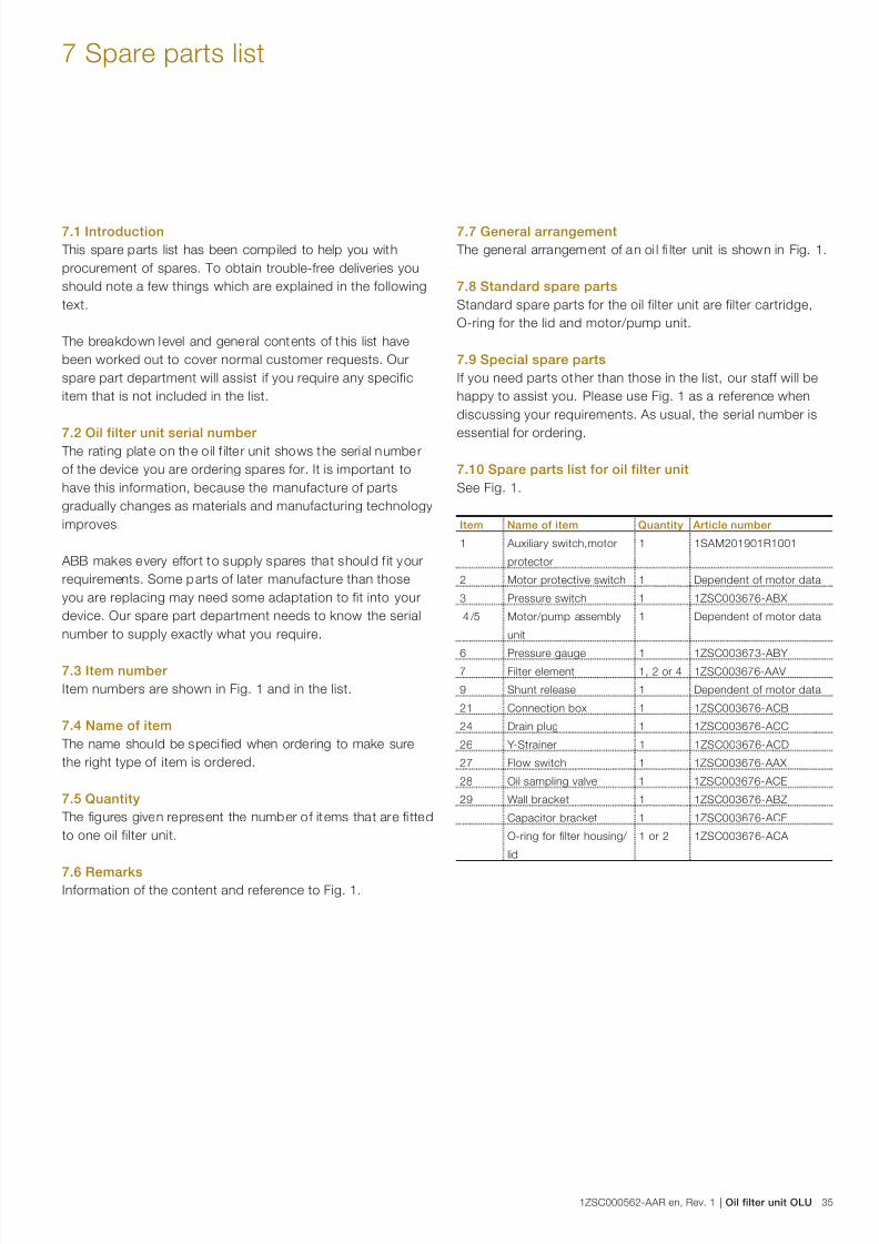
7.1 Introduction
This spare parts list has been compiled to help you with
procurement of spares. To obtain trouble-free deliveries you
should note a few things which are explained in the following
text.
The breakdown level and general contents of this list have
been worked out to cover normal customer requests. Our
spare part department will assist if you require any specific
item that is not included in the list.
7.2 Oil filter unit serial number The rating plate on the oil f ilte r unit shows the serial number
of the device you are ordering spares for. It is important to
have this information, because the manufacture of parts
gradually changes as materials and manufacturing technology
improves.
ABB makes every effor t to supply spares that should f it your
requirements. Some parts of later manufacture than those
you are replacing may need some adaptation to fit into your
device. Our spare part department needs to know the serial
number to supply exactly what you require.
7.3 Item number
Item numbers are shown in Fig. 1 and in the list.
7.4 Name of item
The name should be speci fied when ordering to make sure
the right type of item is ordered.
7.5 Quantity
The figures given represent the number of items that are fi tted
to one oil filter unit.
7.6 RemarksInformation of the content and reference to Fig. 1.
7.7 General arrangement
The general arrangement of an oi l fi lter unit is shown in Fig. 1.
7.8 Standard spare parts
Standard spare parts for the oil filter unit are filter cartridge,
O-ring for the lid and motor/pump unit.
7.9 Special spare parts
If you need parts other than those in the list, our staff will be
happy to assist you. Please use Fig. 1 as a reference when
discussing your requirements. As usual, the serial number is
essential for ordering.
7.10 Spare parts list for oil filter unit
See Fig. 1.
Item Name of item Quantity Article number
1 Auxiliary switch,motor
protector
1 1SAM201901R1001
2 Motor protective switch 1 Dependent of motor data
3 Pressure switch 1 1ZSC003676-ABX
4 /5 Motor/pump assembly
unit
1 Dependent of motor data
6 Pressure gauge 1 1ZSC003673-ABY
7 Filter element 1, 2 or 4 1ZSC003676-AAV
9 Shunt release 1 Dependent of motor data
21 Connection box 1 1ZSC003676-ACB
24 Drain plug 1 1ZSC003676-ACC
26 Y-Strainer 1 1ZSC003676-ACD
27 Flow switch 1 1ZSC003676-AAX
28 Oil sampling valve 1 1ZSC003676-ACE
29 Wall bracket 1 1ZSC003676-ABZ
Capacitor bracket 1 1ZSC003676-ACF
O-ring for filter housing/
lid
1 or 2 1ZSC003676-ACA

7/24/2019 1zsc000562-Aar en Rev 1
http://slidepdf.com/reader/full/1zsc000562-aar-en-rev-1 36/4036 Oil filter unit OLU | 1ZSC000562-AAR en, Rev. 1
8 Recycling
8.1 Introduction
The following instructions should only be seen as
recommendations for environmentally sound disposal of
machines. It is the customer's responsibility to ensure that
local regulations are followed.
8.2 Recycling of packaging material
Once the oil filter unit has arrived on site, the packaging
material will need to be removed.
– Any wood packaging can be burned. For some countries,
the packaging used for shipping by sea is made of
impregnated wood that must be recycled according tolocal regulations.
– Plastic wrappings can be recycled.
8.3 Scrapping and destruction
The end user has to, when the equipment has served i ts time,
take care to the current practice and local regulations for
scrapping and destruction.
8.4 Approximate material content
The materia l used in manufacturing of the oil filter unit is
mainly stainless steel and carbon steel. Also a minor part of,
among others, copper, plastics and rubber are included.
8.5 Hazardous waste
The oil from the filter unit is a hazardous waste and has to be
handled according to local instructions.

7/24/2019 1zsc000562-Aar en Rev 1
http://slidepdf.com/reader/full/1zsc000562-aar-en-rev-1 37/40

7/24/2019 1zsc000562-Aar en Rev 1
http://slidepdf.com/reader/full/1zsc000562-aar-en-rev-1 38/40

7/24/2019 1zsc000562-Aar en Rev 1
http://slidepdf.com/reader/full/1zsc000562-aar-en-rev-1 39/40

7/24/2019 1zsc000562-Aar en Rev 1
http://slidepdf.com/reader/full/1zsc000562-aar-en-rev-1 40/40
Contact us
© C o p y r i g h t 2 0 1 4 A B B , A l l r i g h t s r e s e r v e d .
1 Z S C 0 0 0 5 6 2 - A A R
e n , R e v . 1 , 2 0 1 4 - 0 8 - 1 5 ABB AB
Components
SE-771 80 Ludvika, Sweden
Phone: +46 240 78 20 00
Fax: +46 240 121 57
E-Mail: [email protected]
www.abb.com/electricalcomponents
Related Documents