TM Ⅱ 185 Ⅱ 186 TM

Welcome message from author
This document is posted to help you gain knowledge. Please leave a comment to let me know what you think about it! Share it to your friends and learn new things together.
Transcript

TM
Ⅱ̶185 Ⅱ̶186
TM
1N=0.102kgf=0.2248lbs.1mm=0.03937inch
TM
Driving method
Linear motion rolling guide
Built-in lubrication part
Material of table and bed
Sensor
Positioning repeatability
Positioning accuracy
Lost motion
Parallelism in table motion A
Parallelism in table motion B
Attitude accuracy
Straightness
Backlash
±0.001~0.002
0.015
−
−
−
−
−
−
Precision ball screw
Linear Way(ball type)
No built-in
Stainless steel
Select by identification number
Micro Precision Positioning Table TM
Bed
Cover
Sensor
Ball screw
Linear Way
Slide table
Angular bearing
Motor
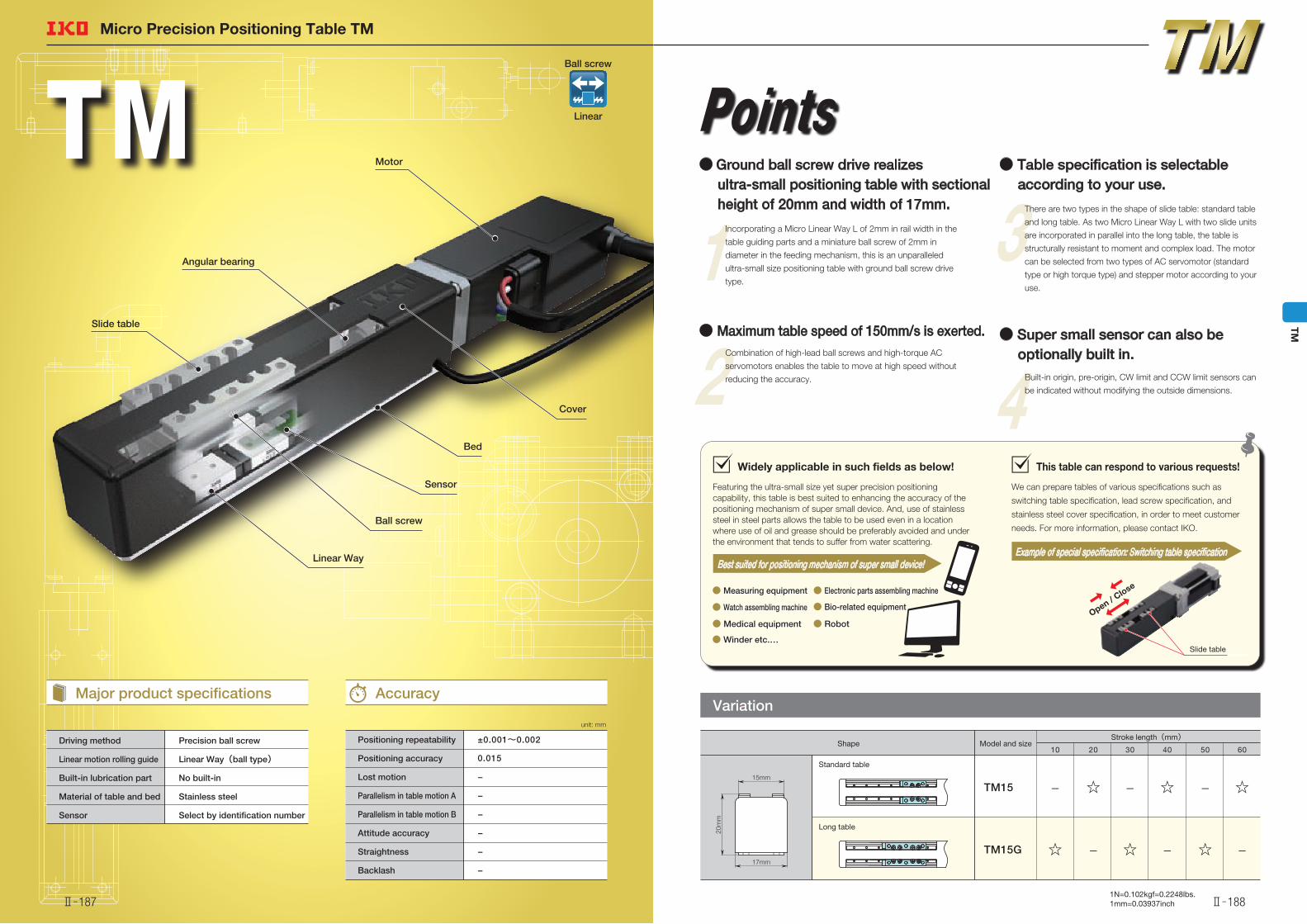
Featuring the ultra-small size yet super precision positioning capability, this table is best suited to enhancing the accuracy of the positioning mechanism of super small device. And, use of stainless steel in steel parts allows the table to be used even in a location where use of oil and grease should be preferably avoided and under the environment that tends to suffer from water scattering.
Widely applicable in such fields as below!
● Winder etc.…● Winder etc.…
● Measuring equipment● Measuring equipment
● Robot● Robot
● Electronic parts assembling machine● Electronic parts assembling machine
● Medical equipment● Medical equipment
● Watch assembling machine● Watch assembling machine ● Bio-related equipment● Bio-related equipmentOpen / C
lose
We can prepare tables of various specifications such as
switching table specification, lead screw specification, and
stainless steel cover specification, in order to meet customer
needs. For more information, please contact IKO.
This table can respond to various requests!
Best suited for positioning mechanism of super small device!Example of special specification: Switching table specification
Slide table
17mm
20m
m
15mm
Points
1 Incorporating a Micro Linear Way L of 2mm in rail width in the
table guiding parts and a miniature ball screw of 2mm in
diameter in the feeding mechanism, this is an unparalleled
ultra-small size positioning table with ground ball screw drive
type.
2 Combination of high-lead ball screws and high-torque AC
servomotors enables the table to move at high speed without
reducing the accuracy.
3 There are two types in the shape of slide table: standard table
and long table. As two Micro Linear Way L with two slide units
are incorporated in parallel into the long table, the table is
structurally resistant to moment and complex load. The motor
can be selected from two types of AC servomotor (standard
type or high torque type) and stepper motor according to your
use.
4 Built-in origin, pre-origin, CW limit and CCW limit sensors can
be indicated without modifying the outside dimensions.
Variation
Shape Model and sizeStroke length(mm)
TM15G
TM15
Standard table
Long table
605040302010
−☆−☆−☆
☆−☆− ☆−
unit: mm
Major product specifications Accuracy
● Ground ball screw drive realizes ultra-small positioning table with sectional height of 20mm and width of 17mm.
● Table specification is selectable according to your use.
● Super small sensor can also be optionally built in.
● Maximum table speed of 150mm/s is exerted.
Ball screw
Linear
Ⅱ̶187 Ⅱ̶188
TM
1N=0.102kgf=0.2248lbs.1mm=0.03937inch
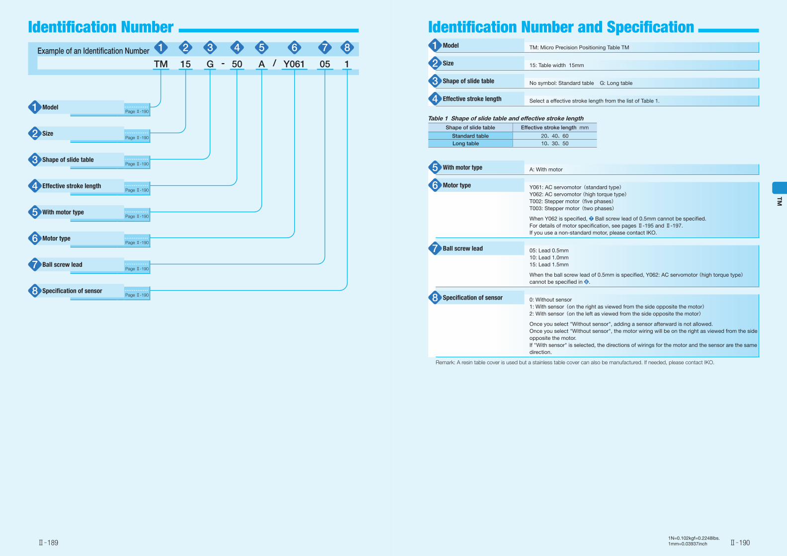
Example of an Identification Number 1 2 3 4 5 6 7 8
TM 15 G - 50 A / Y061 05 1
Page Ⅱ-190
Page Ⅱ-190
Page Ⅱ-190
Page Ⅱ-190
Page Ⅱ-190
Page Ⅱ-190
Page Ⅱ-190
Page Ⅱ-190
TM: Micro Precision Positioning Table TM
15: Table width 15mm
No symbol: Standard table G: Long table
Select a effective stroke length from the list of Table 1.
A: With motor
Y061: AC servomotor(standard type) Y062: AC servomotor (high torque type)T002: Stepper motor(five phases)T003: Stepper motor(two phases)
When Y062 is specified, 7 Ball screw lead of 0.5mm cannot be specified. For details of motor specification, see pages Ⅱ-195 and Ⅱ-197. If you use a non-standard motor, please contact IKO.
05: Lead 0.5mm10: Lead 1.0mm15: Lead 1.5mm
When the ball screw lead of 0.5mm is specified, Y062: AC servomotor (high torque type) cannot be specified in 6 .
0: Without sensor1: With sensor(on the right as viewed from the side opposite the motor)2: With sensor(on the left as viewed from the side opposite the motor)
Once you select "Without sensor", adding a sensor afterward is not allowed.Once you select "Without sensor", the motor wiring will be on the right as viewed from the side opposite the motor.If "With sensor" is selected, the directions of wirings for the motor and the sensor are the same direction.
Remark: A resin table cover is used but a stainless table cover can also be manufactured. If needed, please contact IKO.
Table 1 Shape of slide table and effective stroke lengthShape of slide table Effective stroke length mm
Standard table 20、40、60Long table 10、30、50
Model1
Size2
Shape of slide table3
Effective stroke length4
With motor type5
Motor type6
Ball screw lead7
Specification of sensor8
Model1
Size2
Shape of slide table3
Effective stroke length4
With motor type5
Motor type6
Ball screw lead7
Specification of sensor 8
Ⅱ̶189 Ⅱ̶190
TM
Identification Number Identification Number and Specification
1N=0.102kgf=0.2248lbs.1mm=0.03937inch
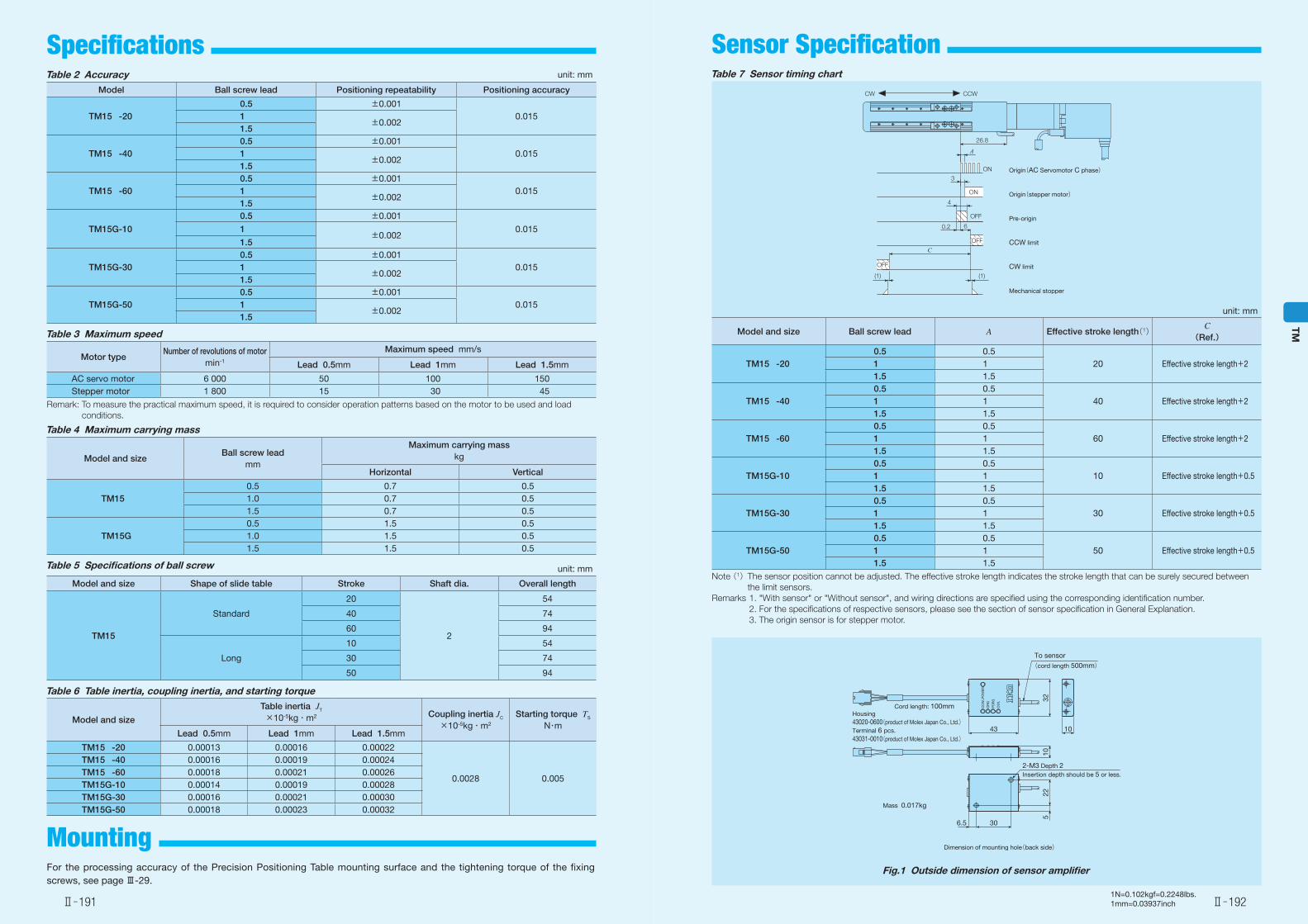
Table 7 Sensor timing chart
4
6
A
CW CCW
C
0.2
26.8
3
ON
OFF
ON
OFF
OFF
(1) (1)
Origin(AC Servomotor C phase)
Origin(stepper motor)
Pre-origin
CCW limit
CW limit
Mechanical stopper
unit: mm
Model and size Ball screw lead A Effective stroke length(1)C
(Ref.)
TM15 -200.5 0.5
20 Effective stroke length+21 11.5 1.5
TM15 -400.5 0.5
40 Effective stroke length+21 11.5 1.5
TM15 -600.5 0.5
60 Effective stroke length+21 11.5 1.5
TM15G-100.5 0.5
10 Effective stroke length+0.51 11.5 1.5
TM15G-300.5 0.5
30 Effective stroke length+0.51 11.5 1.5
TM15G-500.5 0.5
50 Effective stroke length+0.51 11.5 1.5
Note (1) The sensor position cannot be adjusted. The effective stroke length indicates the stroke length that can be surely secured between the limit sensors.
Remarks 1. "With sensor" or "Without sensor", and wiring directions are specified using the corresponding identification number. 2. For the specifications of respective sensors, please see the section of sensor specification in General Explanation. 3. The origin sensor is for stepper motor.
Housing43020-0600(product of Molex Japan Co., Ltd.)Terminal 6 pcs.43031-0010(product of Molex Japan Co., Ltd.)
43
6.5 30
522
32
10
Dimension of mounting hole(back side)
10
PO
WER
CC
WL
OR
G
PO
RG
CW
L
Cord length: 100mm
To sensor(cord length 500mm)
2-M3 Depth 2Insertion depth should be 5 or less.
Mass 0.017kg
Fig.1 Outside dimension of sensor amplifier
Table 2 Accuracy unit: mm
Model Ball screw lead Positioning repeatability Positioning accuracy
TM15 -200.5 ±0.001
0.0151±0.002
1.5
TM15 -400.5 ±0.001
0.0151±0.002
1.5
TM15 -600.5 ±0.001
0.0151±0.002
1.5
TM15G-10
0.5 ±0.0010.0151
±0.0021.5
TM15G-300.5 ±0.001
0.0151±0.002
1.5
TM15G-500.5 ±0.001
0.0151±0.002
1.5
Table 3 Maximum speed
Motor typeNumber of revolutions of motor
min-1
Maximum speed mm/s
Lead 0.5mm Lead 1mm Lead 1.5mm
AC servo motor 6 000 50 100 150Stepper motor 1 800 15 30 45
Remark: To measure the practical maximum speed, it is required to consider operation patterns based on the motor to be used and load conditions.
Table 6 Table inertia, coupling inertia, and starting torque
Model and size
Table inertia JT
×10-5kg・m2 Coupling inertia JC
×10-5kg・m2
Starting torque TS
N・mLead 0.5mm Lead 1mm Lead 1.5mm
TM15 -20 0.00013 0.00016 0.00022
0.0028 0.005
TM15 -40 0.00016 0.00019 0.00024 TM15 -60 0.00018 0.00021 0.00026 TM15G-10 0.00014 0.00019 0.00028TM15G-30 0.00016 0.00021 0.00030TM15G-50 0.00018 0.00023 0.00032
Table 5 Specifications of ball screw unit: mm
Model and size Shape of slide table Stroke Shaft dia. Overall length
TM15
Standard
20
2
54
40 74
60 94
Long
10 54
30 74
50 94
Table 4 Maximum carrying mass
Model and sizeBall screw lead
mm
Maximum carrying masskg
Horizontal Vertical
TM150.5 0.7 0.51.0 0.7 0.51.5 0.7 0.5
TM15G0.5 1.5 0.51.0 1.5 0.51.5 1.5 0.5
For the processing accuracy of the Precision Positioning Table mounting surface and the tightening torque of the fixing screws, see page Ⅲ-29.
Mounting
Ⅱ̶191 Ⅱ̶192
TM
Specifications Sensor Specification
1N=0.102kgf=0.2248lbs.1mm=0.03937inch
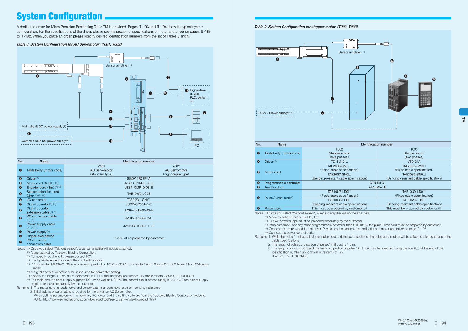
A dedicated driver for Micro Precision Positioning Table TM is provided. Pages Ⅱ-193 and Ⅱ-194 show its typical system configuration. For the specifications of the driver, please see the section of specifications of motor and driver on pages Ⅱ-189 to Ⅱ-192. When you place an order, please specify desired identification numbers from the list of Tables 8 and 9.
Table 8 System Configuration for AC Servomotor (Y061, Y062)
●❽
●❺
●
●❼●❹
●❷
●❸
●
●
●❻
●PC
●❾
●
Sensor amplifier(1)
Higher-level device PLC, switch etc.
Main circuit DC power supply(8)
Control circuit DC power supply(8)
●❶
No. Name Identification number
●❶ Table body (motor code)Y061
AC Servomotor(standard type)
Y062 AC Servomotor
(high torque type)●❷ Driver(2) SGDV-1R7EP1A●❸ Motor cord (3m)(2)(3) JZSP-CF1M20-03-E●❹ Encoder cord (3m)(2)(3) JZSP-CMP10-03-E
●❺ Sensor extension cord (3m)(2)(3)(4) TAE10W0-LC03
●❻ I/O connector TAE20W1-CN(5)●❼ Digital operator(2)(6) JUSP-OP05A-1-E
●❽ Digital operator extension cable(2)(6) JZSP-CF1S00-A3-E
●❾ PC connection cable(2)(6) JZSP-CVS06-02-E
●� Power supply cable(2)(4)(7) JZSP-CF1G00-□□-E
●� Power supply(8)
This must be prepared by customer.●� Higher-level device
●� I/O connector connection cable
Notes (1) Once you select "Without sensor", a sensor amplifier will not be attached. (2) Manufactured by Yaskawa Electric Corporation. (3) For specific cord length, please contact IKO. (4) The higher-level device side of the cord will be loose. (5) I/O connector TAE20W1-CN is a combined product of 10126-3000PE (connector) and 10326-52F0-008 (cover) from 3M Japan
Limited. (6) A digital operator or ordinary PC is required for parameter setting. (7) Specify the length 1 - 3m in 1m increments in □□ of the identification number. (Example for 3m: JZSP-CF1G00-03-E) (8) The main circuit power supply supports DC48V as well as DC24V. The control circuit power supply is DC24V. Each power supply
must be prepared separately by the customer. Remarks 1: The motor cord, encoder cord and sensor extension cord have excellent bending resistance. 2: Initial setting of parameters is required for the driver for AC Servomotor.
When setting parameters with an ordinary PC, download the setting software from the Yaskawa Electric Corporation website. (URL: http://www.e-mechatronics.com/download/tool/servo/sgmwinpls/download.html)
No. Name Identification number
●❶ Table body (motor code)T002
Stepper motor (five phases)
T003 Stepper motor (two phases)
●❷ Driver(2) TD-5M13-L eTD-24A
●❸ Motor cord
TAE20S6-SM0□ (Fixed cable specification)
TAE20S8-SM0□ (Fixed cable specification)
TAE20S7-SN0□ (Bending-resistant cable specification)
TAE20S9-SN0□ (Bending-resistant cable specification)
●❹ Programmable controller CTN481G●❺ Teaching box TAE10M5-TB
●❻ Pulse / Limit cord(4)
TAE10U7-LD0□ (Fixed cable specification)
TAE10U9-LD0□ (Fixed cable specification)
TAE10U8-LD0□ (Bending-resistant cable specification)
TAE10V0-LD0□ (Bending-resistant cable specification)
●❼ Power cord This must be prepared by customer.(5) This must be prepared by customer.(6)Notes (1) Once you select "Without sensor", a sensor amplifier will not be attached. (2) Made by Tohan-Denshi Kiki Co., Ltd. (3) DC24V power supply must be prepared separately by the customer. (4) If the customer uses any other programmable controller than CTN481G, the pulse / limit cord must be prepared by customer. (5) Connectors are provided for the driver. Please see the section of specifications of motor and driver on page Ⅱ-197. (6) Connect the power cord directly. Remarks 1: While the pulse / limit cord includes pulse cord and limit cord sections, the pulse cord section will be a fixed cable regardless of the
cable specifications. 2: The length of pulse cord portion of pulse / limit cord is 1.5 m. 3: The lengths of motor cord and the limit cord portion of pulse / limit cord can be specified using the box (□) at the end of the
identification number, up to 3m in increments of 1m. (For 3m: TAE20S6-SM03)
Table 9 System Configuration for stepper motor(T002, T003)
Sensor amplifier(1)
●❶
●❷
●❸
●❻
●❹●❺
●●❼DC24V Power supply(3)
Ⅱ̶193 Ⅱ̶194
TM
System Configuration
1N=0.102kgf=0.2248lbs.1mm=0.03937inch
2.5
10
□15
20
φ11φ4
48(Y061)
54(Y062)
φ16
45°2-M2 Depth 3
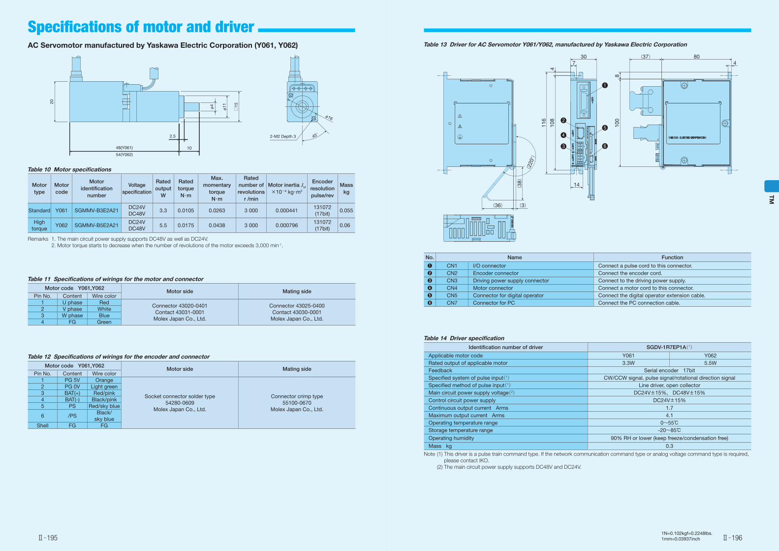
AC Servomotor manufactured by Yaskawa Electric Corporation (Y061, Y062)
Motor type
Motor code
Motor identification
number
Voltage specification
Rated output
W
Rated torqueN・m
Max. momentary
torqueN・m
Rated number of revolutions
r /min
Motor inertia JM
×10-4 kg・m2
Encoder resolutionpulse/rev
Masskg
Standard Y061 SGMMV-B3E2A21DC24VDC48V
3.3 0.0105 0.0263 3 000 0.000441131072 (17bit)
0.055
High torque
Y062 SGMMV-B5E2A21DC24VDC48V
5.5 0.0175 0.0438 3 000 0.000796131072 (17bit)
0.06
Table 10 Motor specifications
Remarks 1. The main circuit power supply supports DC48V as well as DC24V. 2. Motor torque starts to decrease when the number of revolutions of the motor exceeds 3,000 min-1.
Motor code Y061,Y062Motor side Mating side
Pin No. Content Wire color1 U phase Red
Connector 43020-0401 Contact 43031-0001
Molex Japan Co., Ltd.
Connector 43025-0400 Contact 43030-0001
Molex Japan Co., Ltd.
2 V phase White3 W phase Blue4 FG Green
Table 11 Specifications of wirings for the motor and connector
Motor code Y061,Y062Motor side Mating side
Pin No. Content Wire color1 PG 5V Orange
Socket connector solder type 54280-0609
Molex Japan Co., Ltd.
Connector crimp type 55100-0670
Molex Japan Co., Ltd.
2 PG 0V Light green3 BAT(+) Red/pink4 BAT(-) Black/pink5 PS Red/sky blue
6 /PSBlack/
sky blueShell FG FG
Table 12 Specifications of wirings for the encoder and connector
804
(37)
810
0
108
116
730
14
4
(38)
(36) (3)
(22
0°)
●❶
●❷
●❸
●❹●❺
●❻
No. Name Function
●❶ CN1 I/O connector Connect a pulse cord to this connector.●❷ CN2 Encoder connector Connect the encoder cord.●❸ CN3 Driving power supply connector Connect to the driving power supply.●❹ CN4 Motor connector Connect a motor cord to this connector.●❺ CN5 Connector for digital operator Connect the digital operator extension cable.●❻ CN7 Connector for PC Connect the PC connection cable.
Table 14 Driver specificationIdentification number of driver SGDV-1R7EP1A(1)
Applicable motor code Y061 Y062Rated output of applicable motor 3.3W 5.5WFeedback Serial encoder 17bitSpecified system of pulse input(1) CW/CCW signal, pulse signal/rotational direction signalSpecified method of pulse input(1) Line driver, open collectorMain circuit power supply voltage(2) DC24V±15%, DC48V±15%Control circuit power supply DC24V±15%Continuous output current Arms 1.7Maximum output current Arms 4.1Operating temperature range 0~55℃Storage temperature range -20~85℃Operating humidity 90% RH or lower (keep freeze/condensation free)Mass kg 0.3
Note (1) This driver is a pulse train command type. If the network communication command type or analog voltage command type is required, please contact IKO.
(2) The main circuit power supply supports DC48V and DC24V.
Table 13 Driver for AC Servomotor Y061/Y062, manufactured by Yaskawa Electric Corporation
Ⅱ̶195 Ⅱ̶196
TM
Specifications of motor and driver
1N=0.102kgf=0.2248lbs.1mm=0.03937inch
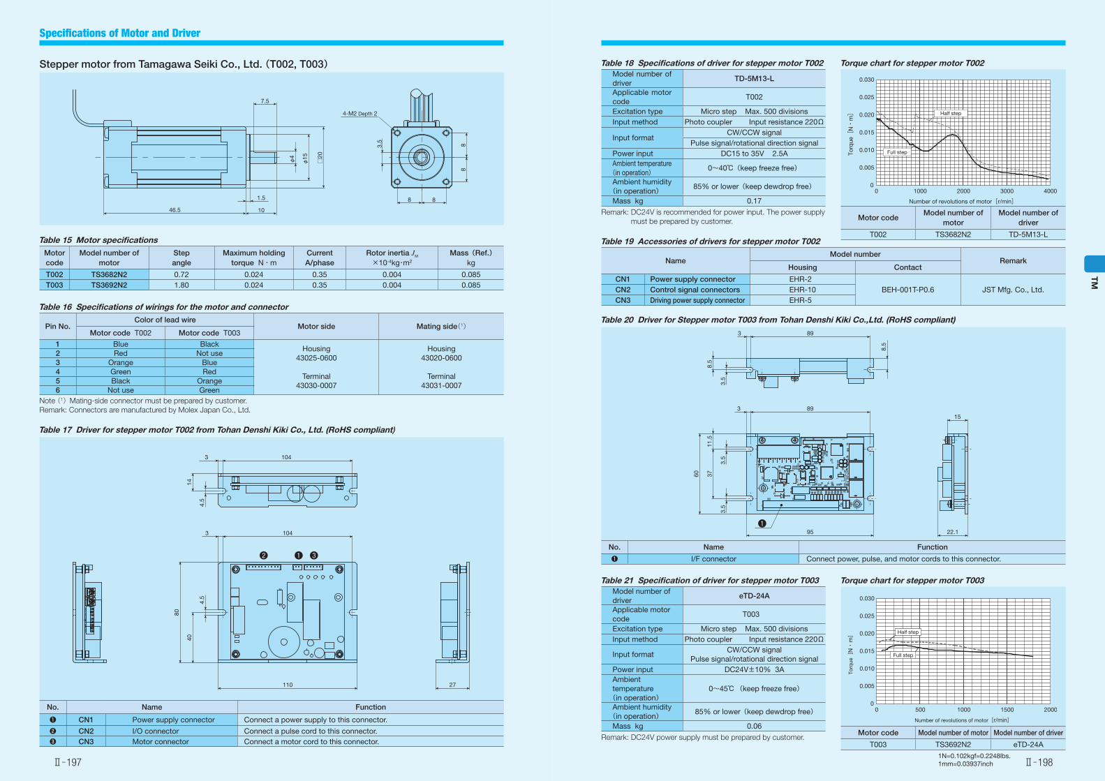
Stepper motor from Tamagawa Seiki Co., Ltd. (T002, T003)
Table 15 Motor specificationsMotor code
Model number of motor
Step angle
Maximum holding torque N・m
CurrentA/phase
Rotor inertia JM
×10-4kg・m2
Mass(Ref.)kg
T002 TS3682N2 0.72 0.024 0.35 0.004 0.085T003 TS3692N2 1.80 0.024 0.35 0.004 0.085
Table 16 Specifications of wirings for the motor and connector
Pin No.Color of lead wire
Motor side Mating side(1)Motor code T002 Motor code T003
1 Blue BlackHousing
43025-0600Housing
43020-06002 Red Not use3 Orange Blue4 Green Red
Terminal43030-0007
Terminal43031-0007
5 Black Orange6 Not use Green
Note (1)Mating-side connector must be prepared by customer.Remark: Connectors are manufactured by Molex Japan Co., Ltd.
Table 17 Driver for stepper motor T002 from Tohan Denshi Kiki Co., Ltd. (RoHS compliant)
No. Name Function
●❶ CN1 Power supply connector Connect a power supply to this connector.●❷ CN2 I/O connector Connect a pulse cord to this connector.●❸ CN3 Motor connector Connect a motor cord to this connector.
φ4
φ15
□20
46.5
1.5
10
7.5
88
8 8
4-M2 Depth 2
3.5
27110
80
40
4.5
3 104
1043
4.5
14
●❸●❶●❷
Table 18 Specifications of driver for stepper motor T002Model number of driver
TD-5M13-L
Applicable motor code
T002
Excitation type Micro step Max. 500 divisionsInput method Photo coupler Input resistance 220Ω
Input formatCW/CCW signal
Pulse signal/rotational direction signalPower input DC15 to 35V 2.5AAmbient temperature(in operation) 0~40℃(keep freeze free)
Ambient humidity(in operation) 85% or lower(keep dewdrop free)
Mass kg 0.17Remark: DC24V is recommended for power input. The power supply
must be prepared by customer.
Table 19 Accessories of drivers for stepper motor T002
NameModel number
RemarkHousing Contact
CN1 Power supply connector EHR-2BEH-001T-P0.6 JST Mfg. Co., Ltd.CN2 Control signal connectors EHR-10
CN3 Driving power supply connector EHR-5
Torque chart for stepper motor T002
Motor codeModel number of
motorModel number of
driver
T002 TS3682N2 TD-5M13-L
Half step
Full step
0 1000 2000 3000 40000
0.005
0.010
0.015
0.020
0.025
0.030
Number of revolutions of motor[r/min]
Torq
ue[
N・
m]
Table 20 Driver for Stepper motor T003 from Tohan Denshi Kiki Co.,Ltd. (RoHS compliant)
No. Name Function
●❶ I/F connector Connect power, pulse, and motor cords to this connector.
60
89
8.5
3
3.5
15
22.1
3711
.5
3.5
3.5
8.5
893
95●❶
Table 21 Specification of driver for stepper motor T003Model number of driver
eTD-24A
Applicable motor code
T003
Excitation type Micro step Max. 500 divisionsInput method Photo coupler Input resistance 220Ω
Input formatCW/CCW signal
Pulse signal/rotational direction signalPower input DC24V±10% 3AAmbient temperature (in operation)
0~45℃(keep freeze free)
Ambient humidity(in operation) 85% or lower(keep dewdrop free)
Mass kg 0.06Remark: DC24V power supply must be prepared by customer.
Torque chart for stepper motor T003
Motor code Model number of motor Model number of driver
T003 TS3692N2 eTD-24A
0
0.005
0.010
0.015
0.020
0.025
0.030
0 500 1000 1500 2000
Half step
Full step
Number of revolutions of motor[r/min]
Torq
ue[
N・
m]
Ⅱ̶197 Ⅱ̶198
TM
Specifications of Motor and Driver
1N=0.102kgf=0.2248lbs.1mm=0.03937inch
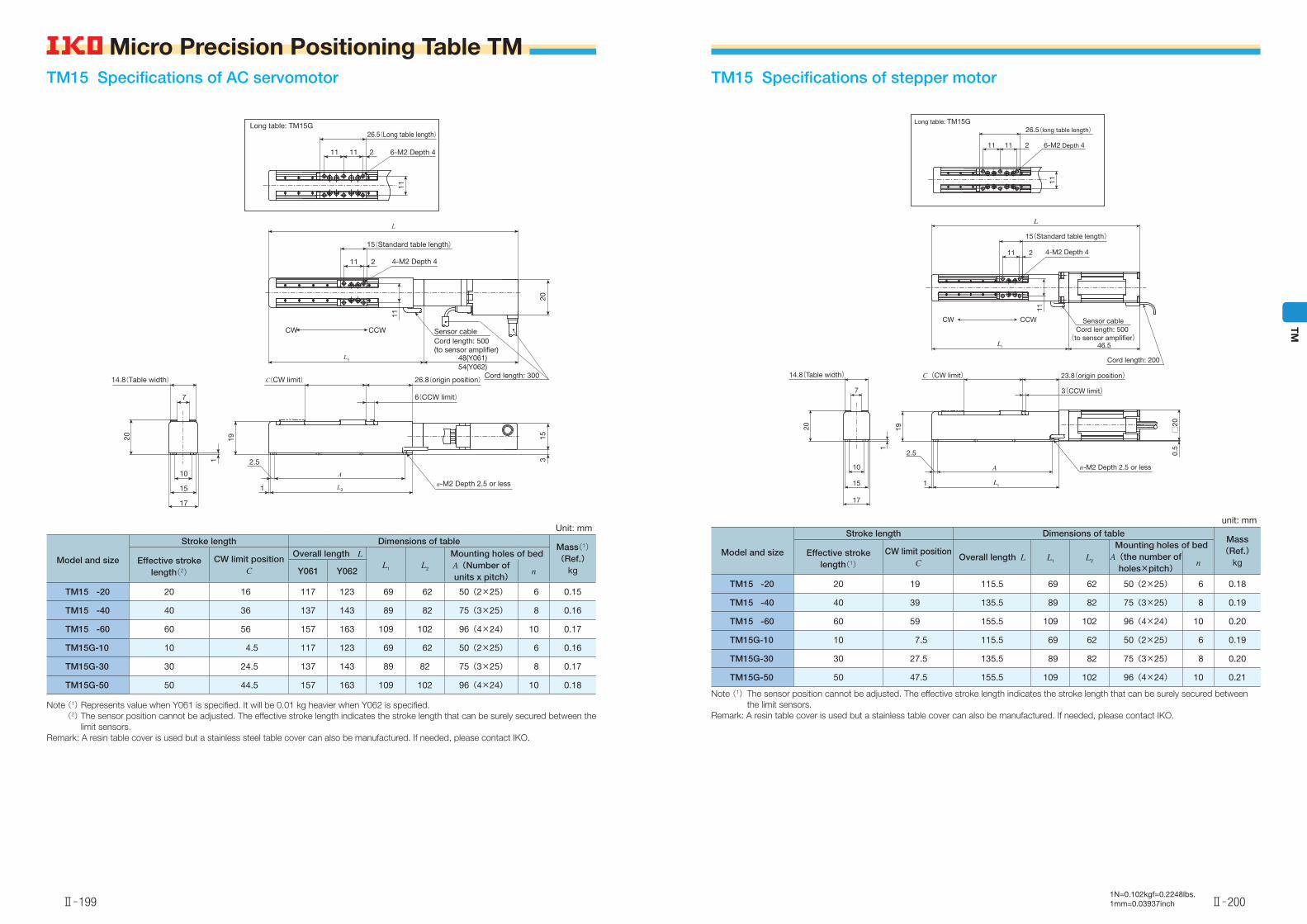
TM15 Specifications of stepper motor
unit: mm
Model and size
Stroke length Dimensions of tableMass(Ref.)
kgEffective stroke
length(1)CW limit position
COverall length L L1 L2
Mounting holes of bedA(the number of
holes×pitch)n
TM15 -20 20 19 115.5 69 62 50(2×25) 6 0.18
TM15 -40 40 39 135.5 89 82 75(3×25) 8 0.19
TM15 -60 60 59 155.5 109 102 96(4×24) 10 0.20
TM15G-10 10 7.5 115.5 69 62 50(2×25) 6 0.19
TM15G-30 30 27.5 135.5 89 82 75(3×25) 8 0.20
TM15G-50 50 47.5 155.5 109 102 96(4×24) 10 0.21
Note (1) The sensor position cannot be adjusted. The effective stroke length indicates the stroke length that can be surely secured between the limit sensors.
Remark: A resin table cover is used but a stainless table cover can also be manufactured. If needed, please contact IKO.
211
CW CCW
11
0.5
A
2.5
1
7
20
10
15
L
19
15(Standard table length)
4-M2 Depth 4
Sensor cableCord length: 500
(to sensor ampli�er)
Cord length: 200
23.8(origin position)
3(CCW limit)
□20
n-M2 Depth 2.5 or less
L1
L2
C(CW limit)14.8(Table width)
1
46.5
17
11
21111
Long table: TM15G26.5(long table length)
6-M2 Depth 4
TM15 Specifications of AC servomotor
Unit: mm
Model and size
Stroke length Dimensions of tableMass(1)(Ref.)
kgEffective stroke
length(2)CW limit position
C
Overall length LL1 L2
Mounting holes of bed
Y061 Y062A(Number of units x pitch)
n
TM15 -20 20 16 117 123 69 62 50(2×25) 6 0.15
TM15 -40 40 36 137 143 89 82 75(3×25) 8 0.16
TM15 -60 60 56 157 163 109 102 96(4×24) 10 0.17
TM15G-10 10 4.5 117 123 69 62 50(2×25) 6 0.16
TM15G-30 30 24.5 137 143 89 82 75(3×25) 8 0.17
TM15G-50 50 44.5 157 163 109 102 96(4×24) 10 0.18
211
CW CCW
11
3
A
2.5
1
7
20
10
15
L19
Long table: TM15G
15(Standard table length)
4-M2 Depth 4
Sensor cableCord length: 500 (to sensor amplifier)
Cord length: 30026.8(origin position)
6(CCW limit)
15
n-M2 Depth 2.5 or less
L1
L2
C(CW limit)14.8(Table width)
1
48(Y061)54(Y062)
17
11
21111
26.5(Long table length)
6-M2 Depth 4
20
Note (1) Represents value when Y061 is specified. It will be 0.01 kg heavier when Y062 is specified. (2) The sensor position cannot be adjusted. The effective stroke length indicates the stroke length that can be surely secured between the
limit sensors. Remark: A resin table cover is used but a stainless steel table cover can also be manufactured. If needed, please contact IKO.
Ⅱ̶199 Ⅱ̶200
TM
Micro Precision Positioning Table TM
Related Documents