For Support Contact +46 8 25 28 75 Or [email protected] 1802-2017003 R09, 2019-02-13 USER GUIDE ETM-PURPLE Intelligent Tri-Mode Terminal Features: • Intelligent Tri-Mode Terminal in small form factor • 2G/3G/4G (GPRS/UMTS/LTE) Connectivity • SMS, IP or CSD operation and configuration • Standard RS232 or RS485 serial port • High speed USB • 5V to 35V power input • Power failure alarm (Last gasp) • FME M antenna connector • Signal strength LED indicator • User configurable via configuration tool and ETM Web Office

Welcome message from author
This document is posted to help you gain knowledge. Please leave a comment to let me know what you think about it! Share it to your friends and learn new things together.
Transcript

For Support Contact +46 8 25 28 75 Or [email protected]
1802-2017003 R09, 2019-02-13
USER GUIDE
ETM-PURPLE Intelligent Tri-Mode Terminal
Features: • Intelligent Tri-Mode Terminal in small form factor
• 2G/3G/4G (GPRS/UMTS/LTE) Connectivity
• SMS, IP or CSD operation and configuration
• Standard RS232 or RS485 serial port
• High speed USB
• 5V to 35V power input
• Power failure alarm (Last gasp)
• FME M antenna connector
• Signal strength LED indicator
• User configurable via configuration tool and ETM Web Office

For Support Contact +46 8 25 28 75 Or [email protected]
1802-2017003 R09, 2019-02-13
TABLE OF CONTENT Table of content .............................................................................................................................................. 2Introduction ..................................................................................................................................................... 3
Nomenclature ................................................................................................................................................ 3Terminal Nomenclature/History ..................................................................................................................... 3Overview ....................................................................................................................................................... 4Applications ................................................................................................................................................... 4Tri-Mode Operation ....................................................................................................................................... 5
Physical Dimensions ...................................................................................................................................... 7Separate Power RJ12 & Serial 10 pin Boxhead Connector ........................................................................ 7Combined Power & Serial RJ45 Connector .................................................................................................. 9USB Communications Port ............................................................................................................................ 9Antenna .......................................................................................................................................................... 10SIM Card ........................................................................................................................................................ 10
SIM Pin .................................................................................................................................................... 11Indicator Lights ............................................................................................................................................. 11
LED Behaviour - Normal Start Sequence ................................................................................................... 11Green LEDs ................................................................................................................................................ 12Orange LEDs .............................................................................................................................................. 12
Installation ..................................................................................................................................................... 14Initial Start-up & Configuration .................................................................................................................... 14
Typical Startup Sequence ........................................................................................................................... 15ET Mode/Configuration ................................................................................................................................ 16
Putting the Unit into ESC Mode .................................................................................................................. 16ET Command Table .................................................................................................................................... 18
Last Gasp Mode Operation .......................................................................................................................... 22AT Mode Operation ....................................................................................................................................... 23
Common useful AT commands for basic operation include: ....................................................................... 23SMS Specific Commands ........................................................................................................................... 25AT Commands for Incoming Circuit Switch Data Calls ............................................................................... 25
JET Mode Operation ..................................................................................................................................... 26JET Command table ................................................................................................................................... 26
JET Configuration change responses ..................................................................................................... 28Installing the configuration tool in Windows 7. ............................................................................................ 29
Local configuration .................................................................................................................................. 35

Page 3 of 48
For Support Contact +46 8 25 28 75 Or [email protected]
INTRODUCTION Nomenclature
The ETM Purple variants incorporate the Cinterion BGS2, BGS5, EHS5, EHS6 or ELS61
module and are intended for worldwide use (network and regulatory approvals permitting).
Terminal Nomenclature/History
DESCRIPTION PART # MODULE INSTALLED
ETM Purple 2G, RJ12, Boxhead 71271 BGS2-E
ETM Purple 2G, RJ12, Boxhead, USB 71272 BGS5-E
ETM Purple 2G/3G Penta Band, RJ45, USB 71280 EHS6
ETM Purple 2G/3G Penta Band, RJ12, Box head, USB, Last Gasp
71284 EHS6
ETM Purple 2G/3G/4G, E-band, RJ45, USB 71423 ELS61-E
ETM Purple 2G/3G/4G, RJ12, Boxhead, USB, Last Gasp
71426 ELS61-E
ETM Purple 3G/4G US-Band, RJ45, USB
71355 ELS61-US
ETM Purple 3G/4G US-Band, RJ12, Boxhead, USB, Last Gasp
71356 ELS61-US
ETM Purple 3G/4G AUS-Band, RJ45, USB
71357 ELS61-AUS
Page 4 of 48
For Support Contact +46 8 25 28 75 Or [email protected]
Overview The ETM Purple range of products, are intelligent industrial terminals designed for M2M
(Machine to Machine) communications. With 2G/3G & 4G connectivity, intelligent Tri-Mode
operation and small form factor they provide the ideal communications solution for electrical
metering or other applications utilising serial communications.
Applications Typical applications include:
◩ RS232, RS422/485 or USB communications interface for electrical meters and data
concentrators
◩ Serial communications interface for other devices such as PLC’s, Irrigation controls,
Security and/or access systems, data loggers
◩ As a device for sending SMS alarms notifications based on AT commands from a connected
PLC, PC or Server

Page 5 of 48
For Support Contact +46 8 25 28 75 Or [email protected]
Tri-Mode Operation The unit can be operated in a number of ways to achieve different functional outcomes,
depending on the requirements of the device to which the unit is connected, and/or the
interaction with any back-end/server. The ETM Purple can support CSD or IP connections
and SMS configuration or status queries.
The following is a simplified block schematic to assist in understanding the operational
capabilities of the unit.
External Processor ET Commands
Java Engine JET Mode
EHS5/6 Wireless Module AT Commands
ETM Purple Tri-Mode Intelligent terminal
RS232 Serial ET Mode AT Mode JET Mode
USB AT Mode
(Modem Can be powered by USB)
TM

Page 6 of 48
For Support Contact +46 8 25 28 75 Or [email protected]
MODE/COMMAND STRUCTURE PURPOSE INTERFACE METHOD
ET Commands
The external processor is used to control the start sequence of the modem and make default operational settings. It is also used to configure "Last Gasp" functionality (if applicable) and other features.
ET commands sent to serial port if in ESC mode
SMS of a subset of ET commands sent to the units phone number (note SIM needs to have SMS activated)
AT Mode Depending on the setting made above the unit can be operated as a basic 2G/3G/4G modem using AT commands to drive the unit
AT commands sent to the serial or USB port
JET Mode Provides intelligent operational functions such as;
TCP tunnel
CSD tunnel
TCP Server
Serial to TCP Server
Status Logging > sending to server for monitoring (by others)
JET commands sent to the serial port, or by SMS or by TCP
ETM Purple 2G/3G Penta Band, RJ12, Box head, USB, Last Gasp
71284 EHS6
ETM Purple 2G/3G/4G, E-band, RJ45, USB 71423 ELS61-E
ETM Purple 2G/3G/4G, RJ12, Boxhead, USB, Last Gasp
71426 ELS61-E
ETM Purple 3G/4G US-Band, RJ45, USB
71355 ELS61-US
ETM Purple 3G/4G US-Band, RJ12, Boxhead, USB, Last Gasp
71356 ELS61-US
ETM Purple 3G/4G AUS-Band, RJ45, USB
71357 ELS61-AUS
Note that there may be a charge associated with the provision of JET code, and that it is
possible for customers to use the modem and to load their own Java™ code for a specific
application. ETM will not provide un-compiled JET code for use by others, it is the customers
responsibility to develop their own code using the resources available for the BGS5, EHS5,
EHS6 or ELS61 module.

Page 7 of 48
For Support Contact +46 8 25 28 75 Or [email protected]
PHYSICAL DIMENSIONS
SEPARATE POWER RJ12 & SERIAL 10 PIN BOXHEAD CONNECTOR
Some models of ETM Purple utilises a 6-pin RJ12 connector for power, pin allocations are
shown below.
MODEL PART # LOOKING AT MODEM SOCKET
1 Power Supply (+5 to +35VDC) (+7 to 35VDC for Last Gasp)
2 Not Used
3 Not Used
4 Not Used
5 Not Used
6 GND
1 2 3 4 5 6

Page 8 of 48
For Support Contact +46 8 25 28 75 Or [email protected]
Some models of ETM Purple utilises a 10-pin box head connector for communication, pin
allocations are shown below.
PIN FUNCTION LOOKING AT MODEM SOCKET
1 DCD Out
2 DSR Out
3 RXD Out
4 RTS In
5 TXD In
6 CTS Out
7 DTR In
8 RING Out
9 GND
10 Not Used
Page 9 of 48
For Support Contact +46 8 25 28 75 Or [email protected]
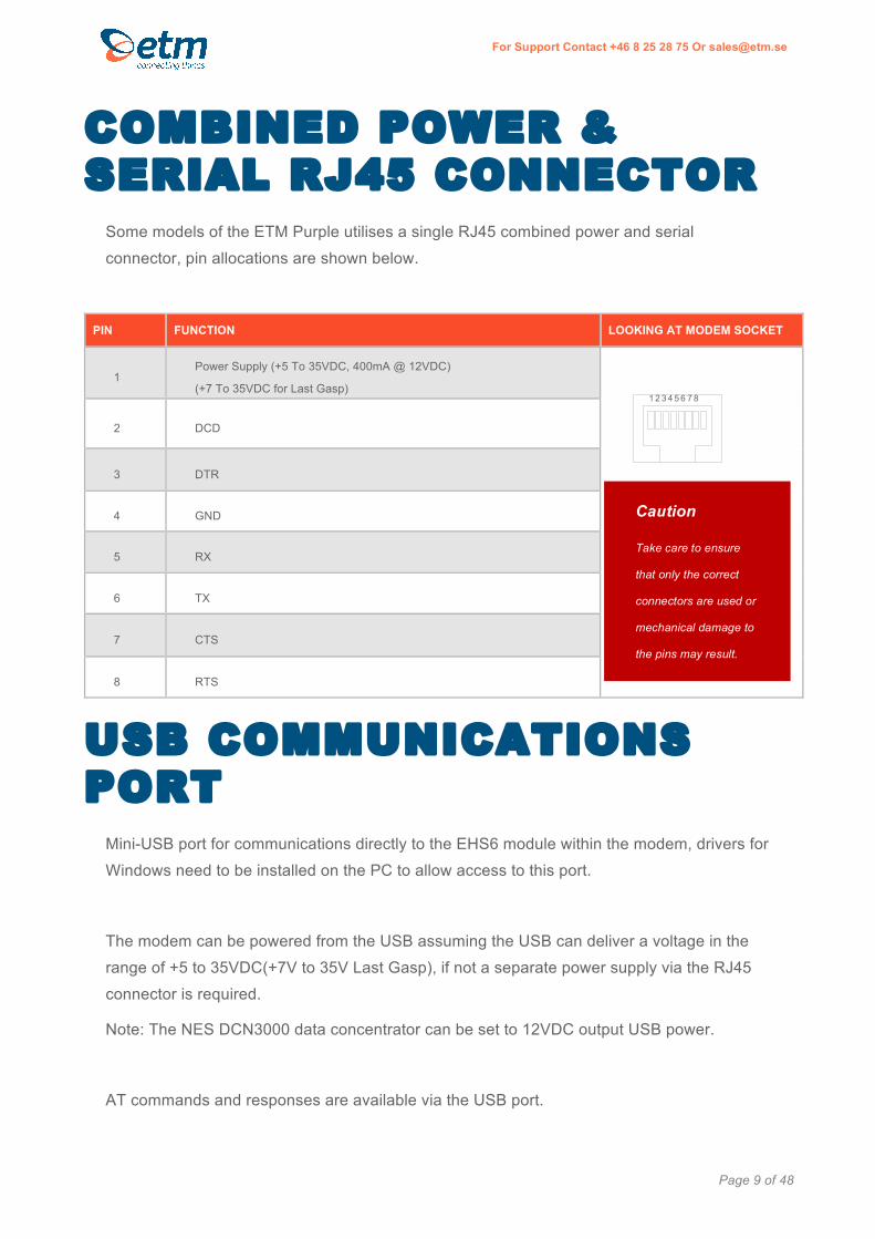
COMBINED POWER & SERIAL RJ45 CONNECTOR
Some models of the ETM Purple utilises a single RJ45 combined power and serial
connector, pin allocations are shown below.
PIN FUNCTION LOOKING AT MODEM SOCKET
1 Power Supply (+5 To 35VDC, 400mA @ 12VDC)
(+7 To 35VDC for Last Gasp)
2 DCD
3 DTR
4 GND
5 RX
6 TX
7 CTS
8 RTS
USB COMMUNICATIONS PORT
Mini-USB port for communications directly to the EHS6 module within the modem, drivers for
Windows need to be installed on the PC to allow access to this port.
The modem can be powered from the USB assuming the USB can deliver a voltage in the
range of +5 to 35VDC(+7V to 35V Last Gasp), if not a separate power supply via the RJ45
connector is required.
Note: The NES DCN3000 data concentrator can be set to 12VDC output USB power.
AT commands and responses are available via the USB port.
Caution
Take care to ensure
that only the correct
connectors are used or
mechanical damage to
the pins may result.
1 2 3 4 5 6 7 8

Page 10 of 48
For Support Contact +46 8 25 28 75 Or [email protected]
ANTENNA The ETM Purple has a standard FME M antenna Plug on the end of an approximately
110mm cable.
FME M Antenna Connector
SIM CARD The SIM card connector is located on the underside of the ETM Purple Terminal. The unit
supports both 3V or 1.8V SIMs. Any SIM card used needs to be correctly provisioned for the
services and network upon which it is intended to be used.
If the terminal is intended to be used for remote access to a device a terminating data
number for Circuit Switch Data (CSD) will need to be provisioned by the network operator,
this number will usually differ from any voice/SMS number. Other key configuration settings
are;
◩ Telstra NextG® SIMs when used for CSD require 2620 bearer capability
Caution
Always disconnect power supply
before inserting or removing SIM Card
Care should be taken in inserting and
removing the SIM card so as not to
damage the SIM holder or cover.

Page 11 of 48
For Support Contact +46 8 25 28 75 Or [email protected]
SIM Pin
If the SIM used has a PIN either;
• The unit can be configured to enter the SIM pin, refer applicable section of this manual
OR
• The SIM PIN should be deactivated, insert the SIM in a mobile phone and deactivate then
transfer the SIM into the ETM Purple unit.
INDICATOR LIGHTS
Looking at underside (SIM access side) of unit.
LED Behaviour - Normal Start Sequence
GreenLED1:ONGreenLED2:ONGreenLED3:ON
GreenLEDsremainON
OrangeLED1:ON(IndicatingthatModulehasbeenfound)
OrangeLED2:ON(IndicatingthatModulehasbeenpowered-upOK)
OrangeLED3:ON(IndicatingthatSIMcardhasbeenfound)
AllLEDsturnOFF
OrangeLED1:Flashing4timesOrangeLED2:Flashing4timesOrangeLED3:Flashing4times
AllLEDsturnOFF
ThenSeeLEDBehaviourBelow
LED 1
LED 2
LED 3
LED 1
LED 2
LED 3
Page 12 of 48
For Support Contact +46 8 25 28 75 Or [email protected]
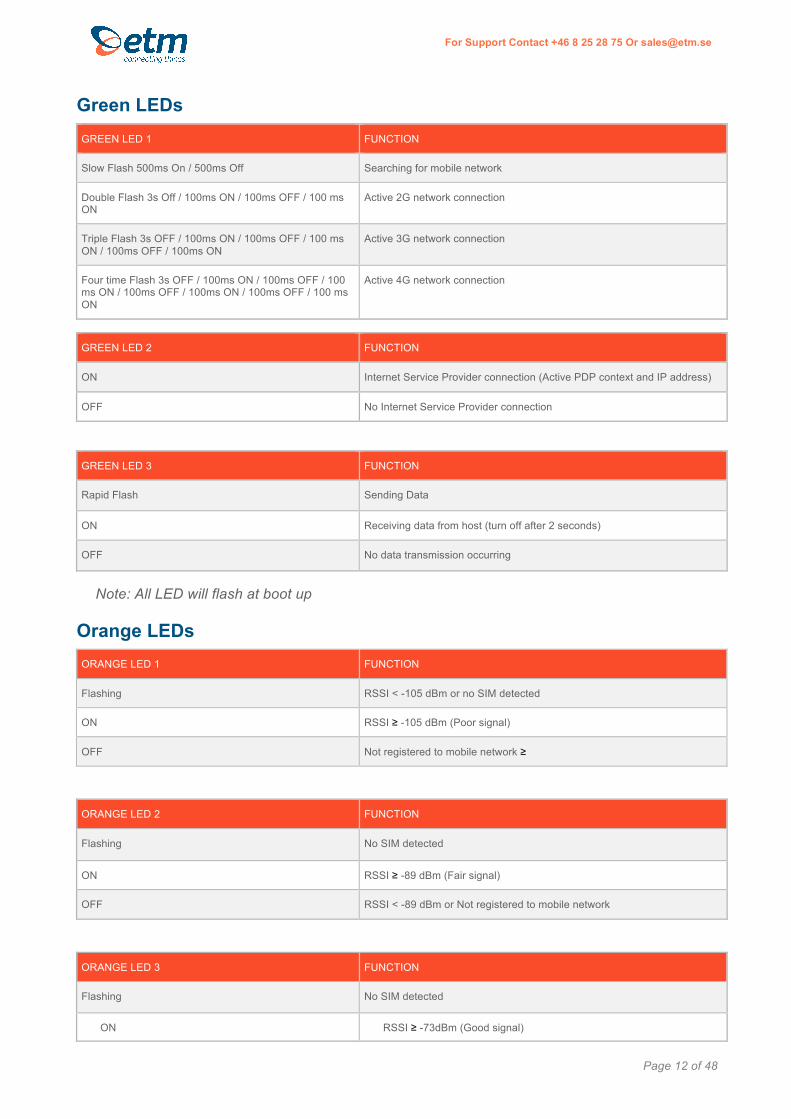
Green LEDs GREEN LED 1 FUNCTION
Slow Flash 500ms On / 500ms Off Searching for mobile network
Double Flash 3s Off / 100ms ON / 100ms OFF / 100 ms ON
Active 2G network connection
Triple Flash 3s OFF / 100ms ON / 100ms OFF / 100 ms ON / 100ms OFF / 100ms ON
Active 3G network connection
Four time Flash 3s OFF / 100ms ON / 100ms OFF / 100 ms ON / 100ms OFF / 100ms ON / 100ms OFF / 100 ms ON
Active 4G network connection
GREEN LED 2 FUNCTION
ON Internet Service Provider connection (Active PDP context and IP address)
OFF No Internet Service Provider connection
GREEN LED 3 FUNCTION
Rapid Flash Sending Data
ON Receiving data from host (turn off after 2 seconds)
OFF No data transmission occurring
Note: All LED will flash at boot up
Orange LEDs ORANGE LED 1 FUNCTION
Flashing RSSI < -105 dBm or no SIM detected
ON RSSI ≥ -105 dBm (Poor signal)
OFF Not registered to mobile network ≥
ORANGE LED 2 FUNCTION
Flashing No SIM detected
ON RSSI ≥ -89 dBm (Fair signal)
OFF RSSI < -89 dBm or Not registered to mobile network
ORANGE LED 3 FUNCTION
Flashing No SIM detected
ON RSSI ≥ -73dBm (Good signal)
Page 13 of 48
For Support Contact +46 8 25 28 75 Or [email protected]
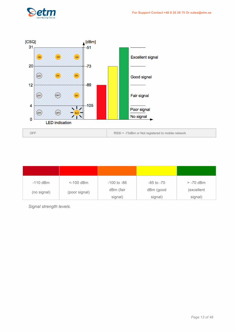
OFF RSSI < -73dBm or Not registered to mobile network
-110 dBm
(no signal)
<-100 dBm
(poor signal)
-100 to -86
dBm (fair
signal)
-85 to -70
dBm (good
signal)
> -70 dBm
(excellent
signal)
Signal strength levels.

Page 14 of 48
For Support Contact +46 8 25 28 75 Or [email protected]
INSTALLATION 1. Connect a suitable serial interface to the modems RJ45 port or 10 pin box header depending
on model, see previous section for pinout details.
2. Fit a suitable antenna to the unit’s FME antenna lead.
3. Install a SIM card enabled for the services you intend to use. If the terminal is intended to be
used for Circuit Switch Data (CSD) a SIM with a terminating data number will need to be
provisioned by the network operator, this number will usually differ from any voice/SMS
number. Note that for Telstra you will need to request;
2620 bearer capability (Telstra NextG™ Sims)
4. Connect the power supply. (The unit accepts a broad range of voltages from +5 to +35VDC)
5. Refer to related sections of this manual for information on configuring the unit for the intended
mode of operation.
INITIAL START-UP & CONFIGURATION
The unit may be delivered in the following states depending on customer request, note that
additional costs may apply for certain functionality.
AS DELIVERED STATE DESCRIPTION START-UP
Standard – no JET Code
Basic modem that may be controlled by AT commands from devices such as a PC, electrical meter or PLC
When the units power is connected and the start-up sequence completed (approximately 20-30 seconds) the serial and USB ports will become available at the set baud rate for AT commands
With JET Code When JET code is installed in the unit custom functionality become available
When power is connected and the start-up sequence completed (approximately 20-30 seconds) the serial and USB ports will become available at the set baud rate for AT commands.
Note that dependant on the JET code and actual state the serial and/or USB ports may not be accessible as they may be busy.
Depending on the configuration settings associated with the JET code the JET code may auto run or be manually started

Page 15 of 48
For Support Contact +46 8 25 28 75 Or [email protected]
Typical Startup Sequence
AT commands may now be sent to the unit.

Page 16 of 48
For Support Contact +46 8 25 28 75 Or [email protected]
ET MODE/CONFIGURATION ET Mode runs in the background irrespective of whether the unit is being used as a basic AT
modem controlled via AT commands from a connected device, or the JET functionality is
being used. ET mode enables configuration of the unit to run in a specific way, controls the
Last Gasp functionality (if applicable) and allows for some SMS based diagnostic queries.
ET commands can be sent to the unit via the serial port (RJ45 or box head) when the unit is
in ESC mode, a subset of the commands may also be sent by SMS to reconfigure the unit or
query the unit's status.
All commands must start with “ET” and end with Carriage Return(<CR> / ASCII 13).
The response will be: “Message Body” + “OK”
Putting the Unit into ESC Mode To enter ESC mode and configure the ET functions the unit must be started while holding the
ESC key down in an active terminal window. The example below uses ETM's Term42
program and valid terminal program will suffice.
1. Open and Setup a suitable Terminal Program
Prior to starting the unit
Open a terminal program and
ensure the correct serial port
is open, the baud rate is
115200 and the cursor is
flashing in the terminal
window

Page 17 of 48
For Support Contact +46 8 25 28 75 Or [email protected]
2. Power up Unit while holding down ESC key
You are now in ESC mode and ET configuration commands and queries can be sent to the
unit.
Make sure you hold the ESC
key on until the unit confirms "Escape Pressed!"

Page 18 of 48
For Support Contact +46 8 25 28 75 Or [email protected]
ET Command Table
ET COMMAND DESCRIPTION COMMAND METHOD
ESC (SERIAL IN ESC MODE), SMS
RESPONSE
ETI Query Modem Information ESC, SMS Modem Info:
VAR:Standard
POWIN:7414mV
MODV:3912mV
CAPV:3712mV
IMEI:004401081945897
SCID:89462046001000364372
MTemp:29degC
BSWS:2.2.6.4
SWS:2.2.9.24
HWS:71357
PCBS:B06031703
SWC:0
PUC:6
PFC:0
MRC:0
Module Info:
ATI1
Cinterion
ELS61-AUS
REVISION 01.001
A-REVISION 00.004.00
ETNET
Query Network Information ESC, SMS Network Info:
SIM:READY(1)
CREG:1
SigQ:8
Operator:"Tele2"
LAC:00D4
CELL:0D4133A
ACT:3G
UARFCN:10787
PSC:275
EC/n0:-6.0
RSCP:-100
ETMCU Query MCU Information ESC, SMS MCU Info:
Bootloader version:2.2.6.4,Build time: Jan 26 2017 10:18:49
Firmware version:ETM Purple SW:2.2.9.24, SVN version: TBD:TBD, Build time: Feb 1 2017 10:00:39
Binary image size:82420 bytes
STM32 SOC ID:0x4321554238314746ffff0033
FLASH size:256kb
ET&V Query Active Profile ESC, SMS PROFILE:
CID:001
LGNR:+46709032555026
IPADD:000.77.219.177:8608
APN:maingatelan.telia.se

Page 19 of 48
For Support Contact +46 8 25 28 75 Or [email protected]
HSD:10(min)
HSP:10(min)
LGPFT:0(s)
LGBT:3600(s)
LGPRT:0(s)
RT:1440(min)
Max SMS limit:50
ET&T Query Timers Profile ESC, SMS TIMERS:
MRTC:00/00/00,00:00:00
RTC:00:02:38(h:m:s)
PFTS:0(s)
RT/RTR:1440/1437(min)
BkpWTR:744(s)
HSPTR:464(s)
HSDTR:464(s)
ETRVL Query CAP Voltage level ESC, SMS CAP VOLT: 3838mv
ETGIS Query Short format Information
ESC, SMS #2,CuID,UID,ETGIS,0,004401081945897,71357*B06031703,2.2.9.24,89462046001000364372,9,OPC,3,00D4,0D4133A,3.706,33,0,0,0#
ETSC1 Set communication to Module mode
Starts the module and switches to AT mode
ESC Powering up modem...
ETRT? Query Reset Timer ESC, SMS Periodic reset timer: 1440min
Time remaining: 1436min
ETSMSML=n Set SMS Max Limit, ETSMSML=n; n=number of SMS max limit before delete
ESC, SMS SMS Max limit set to: 50
ETHSD? Query Hash Send Delay Timer
Periodic Hash send delay: xmin
Time remaining: xxsek
ETHSD=n Set Hash Send Delay Timer, ETHSD=n; n=Delay Time in Minutes
ESC, SMS Periodic Hash send delay set to: 3min
ET COMMAND DESCRIPTION COMMAND METHOD
ESC (SERIAL IN ESC MODE), SMS
RESPONSE
ETHSP? Query Hash Send Periodic Timer
ESC, SMS Periodic Hash send timer: 10min
Time remaining: 272s
ETHSP=n Set Hash Send Periodic Timer, ETHSP=n; n=Time in Minutes
ESC, SMS Periodic Hash send period set to: 10min
ETRT=n Set Reset Timer, ETRT=n; n=Time in seconds
ESC, SMS Periodic reset period set to: 0s
Page 20 of 48
For Support Contact +46 8 25 28 75 Or [email protected]
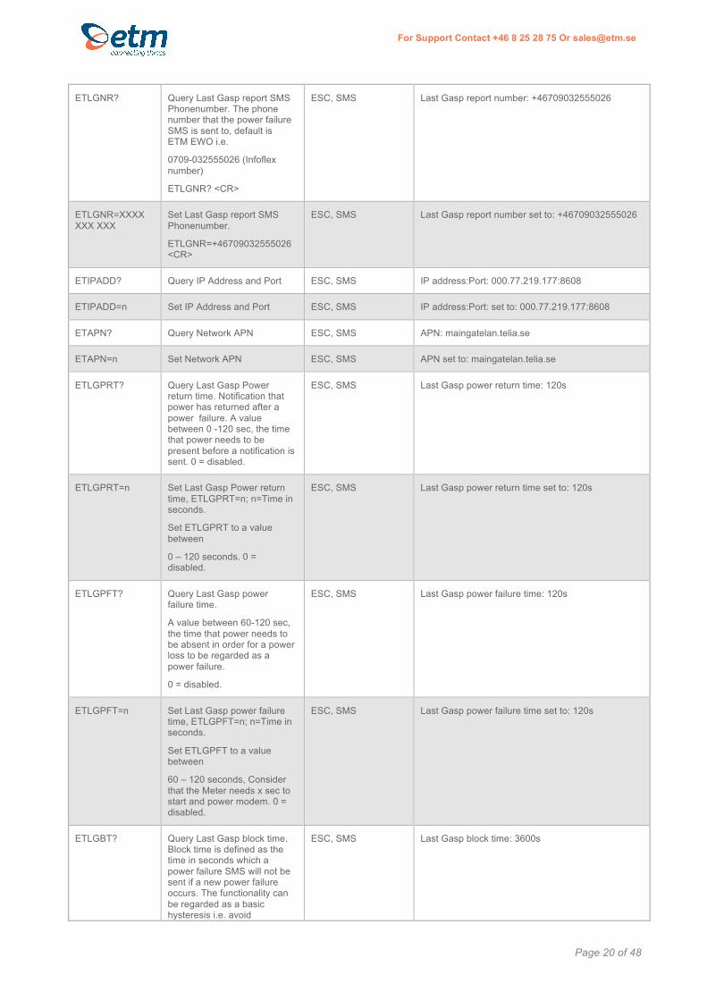
ETLGNR? Query Last Gasp report SMS Phonenumber. The phone number that the power failure SMS is sent to, default is ETM EWO i.e.
0709-032555026 (Infoflex number)
ETLGNR? <CR>
ESC, SMS Last Gasp report number: +46709032555026
ETLGNR=XXXX XXX XXX
Set Last Gasp report SMS Phonenumber.
ETLGNR=+46709032555026<CR>
ESC, SMS Last Gasp report number set to: +46709032555026
ETIPADD? Query IP Address and Port ESC, SMS IP address:Port: 000.77.219.177:8608
ETIPADD=n Set IP Address and Port ESC, SMS IP address:Port: set to: 000.77.219.177:8608
ETAPN? Query Network APN ESC, SMS APN: maingatelan.telia.se
ETAPN=n Set Network APN ESC, SMS APN set to: maingatelan.telia.se
ETLGPRT? Query Last Gasp Power return time. Notification that power has returned after a power failure. A value between 0 -120 sec, the time that power needs to be present before a notification is sent. 0 = disabled.
ESC, SMS Last Gasp power return time: 120s
ETLGPRT=n Set Last Gasp Power return time, ETLGPRT=n; n=Time in seconds.
Set ETLGPRT to a value between
0 – 120 seconds. 0 = disabled.
ESC, SMS Last Gasp power return time set to: 120s
ETLGPFT? Query Last Gasp power failure time.
A value between 60-120 sec, the time that power needs to be absent in order for a power loss to be regarded as a power failure.
0 = disabled.
ESC, SMS Last Gasp power failure time: 120s
ETLGPFT=n Set Last Gasp power failure time, ETLGPFT=n; n=Time in seconds.
Set ETLGPFT to a value between
60 – 120 seconds, Consider that the Meter needs x sec to start and power modem. 0 = disabled.
ESC, SMS Last Gasp power failure time set to: 120s
ETLGBT? Query Last Gasp block time. Block time is defined as the time in seconds which a power failure SMS will not be sent if a new power failure occurs. The functionality can be regarded as a basic hysteresis i.e. avoid
ESC, SMS Last Gasp block time: 3600s

Page 21 of 48
For Support Contact +46 8 25 28 75 Or [email protected]
unwanted rapid switching or in this case avoid several power failure SMS during a defined period
ETLGBT=n Set Last Gasp block time, ETLGBT=n; n=Time in seconds.
Set ETLGBT to a value between 0 – 43200 seconds (12 hours)
ESC, SMS Last Gasp block time set to: 3600s
ETHWS? Query Hardware serial number
ESC, SMS Hardware serial: 71357
ETSWS? Query Software version ESC, SMS Software version: ETM Purple SW:2.2.9.24, SVN version: TBD:TBD, Build time: Feb 1 2017 10:00:39
ETBSWS? Query Bootloader Software version
ESC, SMS Bootloader Software version: 2.2.6.4
ETCC Clear SW-,PU-,PF-Counters ESC, SMS SW-,PU-,PF-,MR-Counter Cleared
ETSEND="ATcmd" Send AT command to module ESC, SMS Response to AT command sent is forward to serial port and/or SMS
ETSJAM=n Send JAVA App cmds to the Module, ETSJAM=n; n=cmd(0=install,1=start,2=stop,3=remove,4=list inst,5=list run)
ESC, SMS Sending command: “ETSJAM=5”
^SJAM: "a:/JRC-1.60.28.jad","Java Remote Control MIDlet Suite","Cinterion","1.60.28",1
^SJAM: "a:/SocketTunnel_QS.jad","SocketTunnel_QS MIDlet Suite","ETM Matteknik AB, ETM Pacific and Tony Kay Pty Ltd","3.3.02770",1
ET&SR Do Software Reset on the MCU
No response, unit will restart
ESC, SMS Shutting down modem...
^SHUTDOWN

Page 22 of 48
For Support Contact +46 8 25 28 75 Or [email protected]
LAST GASP MODE OPERATION
Read ”ET&V” PROFILE by sending ET&V over SMS or serial port:
Example:
CID:001
LGNR:+46709032555026
IPADD:213.115.2.218:3003
APN:4g.tele2.se
HSD:3(min)
HSP:60(min)
LGPFT:60(s)
LGBT:60(s)
LGPRT:60(s)
RT:1440(min)
Max SMS limit:50
For Last Gasp operation, set:
[SMS] Set SMS phone number: ETLGNR=<SMS Phone number>
[TCP/IP] Set IP address and port: ETIPADD=<IP address>:<Port>
Note: If only “SMS”-Last Gasp is desired, set ETIPADD=000, to turn off TCP/IP operation.
Set APN: ETAPN=<apn>
Set Last Gasp Power failure time, ETLGPFT=n; n=Time in seconds
Set Last Gasp Block time, ETLGBT=n; n=Time in seconds
Set Last Gasp Power return time, ETLGPRT=n; n=Time in seconds
Example:
ETLGNR=+46709032555026
ETIPADD=213.115.2.218:3003
ETAPN=4g.tele2.se
ETLGPFT=60
ETLGBT=60
ETLGPRT=60
Last Gasp message protocol structure: #9,Eventcode,ICC(SIMCno),Res,Res,Res,Res,RTC_Date,RTC_Clock,Alarm_counter(Power fail counter),I/O
Alarm_Status(Event ID),Free_text,CapVolt,mV,IMEI,Modultemp
Note: “Res”=Reserved
Example:
#9,3,89462046211101409980,,,,,04/01/06,23:52:15+00,2,8AL,Power Failure,4.370,mV,004401081755155,24,
#9,4,89462046211101409980,,,,,04/01/07,00:00:49+00,3,8ALR,Power
Restored,5.012,mV,004401081755155,25,

Page 23 of 48
For Support Contact +46 8 25 28 75 Or [email protected]
AT MODE OPERATION In AT mode the Terminal can be controlled and by means of AT commands applicable to the
Cinterion EHSx/ELS61 module, AT commands can be sent to either the serial or USB port.
All commands must start with “AT” and end with Carriage Return (<CR> / ASCII 13).
Common useful AT commands for basic operation include: AT COMMAND DESCRIPTION/DETAILS RESPONSE NOTES
ATI Returns Module Name and Firmware Version
Cinterion
EHS6
REVISION 03.001
OK
AT+CPIN=XXXX Allows you to input the SIM card PIN number, if required where XXXX is the PIN number
AT+CPIN? Check the PIN status +CPIN: READY
OK
AT+CSQ returns signal strength e.g. CSQ 11,99 where 11 is the signal and 99 is the service quality
+CSQ: 11,99
OK
AT+CREG? Verifies network registration status, 0 – not registered, 1 – registered, 2 – not registered searching, 3 – registration denied, 5 – registered roaming
+CREG: 0,1
OK
AT+COPS? Indicates connected operator if applicable +COPS: 0,0,"vodafone AU",2
OK
AT&V will return the current settings for the terminal
ACTIVE PROFILE:
E1 Q0 V1 X4 &C1 &D2 &S0 \Q3
S0:000 S3:013 S4:010 S5:008 S6:000 S7:060 S8:000 S10:002
+CBST: 7,0,1
+CRLP: 61,61,78,6
+CR: 0
+CRC: 0
+CMGF: 1
+CSDH: 0

Page 24 of 48
For Support Contact +46 8 25 28 75 Or [email protected]
+CNMI: 1,0,0,0,0
+CMEE: 0
+ICF: 3
+DTMF: 0
+CSMS: 0,1,1,1
+CREG: 0,1
+CLIP: 0,2
+COPS: 0,0,"vodafone AU",2
+CGSMS: 1
OK
AT&W Stores the current configuration of the unit. OK
AT&F sets all current parameters to the manufacturers default profile
OK Caution this may adversely affect the operation of the modem - contact ETM
AT^SCFG=“Radio/Band”,”X”
Sets available radio bands, we recommend using 511, all bands
(where X=radio band setting)
^SCFG: "Radio/Band","511"
OK

Page 25 of 48
For Support Contact +46 8 25 28 75 Or [email protected]
SMS Specific Commands AT COMMAND DESCRIPTION/DETAILS RESPONSE NOTES
AT+CMGF=1 Changes the unit from PDU (Default Setting) to text mode
OK
AT+CSCA? Checks the SMS Central number Normally, this should be read automatically from the SIM Card at start-up
+CSCA: "+61415011501",145
AT+CMGS=“YYYYYYYYYY”
To send a SMS in Text Mode to a mobile number , where YYYYYYYYYY is the mobile phone number
Next, wait for prompt >, then enter the text message followed by the CTRL and Z key together to send the message.
at+cmgs="0414532963"
> test
+CMGS: 112
OK
AT Commands for Incoming Circuit Switch Data Calls AT COMMAND DESCRIPTION/DETAILS RESPONSE NOTES
ATS0=2 Will set the unit to answer an incoming call after 2 rings. Please note that for this to work
the SIM Card must be provisioned with a Terminating Data Number by your network operator.
OK
AT+CRC=1 Sets call type indication, voice or incoming data call. Only terminating data calls displayed as REL ASYNC will be answered.
OK Note, this terminal does not have voice capabilities

Page 26 of 48
For Support Contact +46 8 25 28 75 Or [email protected]
JET MODE OPERATION
Java ETM Terminal (JET) mode operation is controlled by Java™ code embedded within the
BGS5, EHSx or ELS61 module designed to provide additional useful features such as TCP
Threaded Tunnel mode Serial to TCP Tunnel etc.
The JET mode, if installed, will typically run automatically but can be started and stopped by
sending specific commands to the terminal.
The specific operation of the JET mode can be tailored to meet customer requirements via
the setting of various configuration options, these configuration options can be set, in most
cases, via the serial port, by SMS or by TCP/IP.
Some basic useful commands applicable to JET operations are shown below.
JET Command table The most common settings can be performed with the Windows based Configuration tool
(CT) over the USB port. However, these settings and more can also be changed via SMS.
Note that all settings must be saved with JETSAVE in order to be stored in persistent
memory. The commands take effect immediately. Each JET set command answers with
a response number see Jet configuration change response below.
JET COMMAND DESCRIPTION COMMAND METHOD
ESC(RS232 IN ESC MODE), USB, SMS
RESPONSE EXAMPLE
JETI Query status Information.
This information is shown in the CT “Real Time Status” tab.
USB, SMS TCPServerTesting,10/10/11,20160617,144630,3G,10638,-3.5,240,08,017C,0124B95,,TSIP:94.234.165.237:2055,TTTIP:94.234.165.237:2040,,3.3.02763,EHS5-E,2.0,15,12Kb,5Kb,Telenor SE,32,358173052048876,89460862917000109621,30,13,JET
ETSJAM=4 Requests details of JAD file currently installed
SMS If unit has JET functionality installed the file name will be similar to
"a:/SocketTunnel_QS.jad","SocketTunnel_QS MIDIletSuite","ETM Matteknik AB","X.X.XX",X,XXXXX,XXXXXX
Where X reflect the version of JET firmware

Page 27 of 48
For Support Contact +46 8 25 28 75 Or [email protected]
JETSEND=AT&V Will return the current settings for the modem.
USB, SMS JETSEND:
ACTIVE PROFILE:
E0 Q0 V1 X4 &C1 &D2 &S0 \Q3
S0:000 S3:013 S4:010 S5:008 S6:000 S7:060 S8:000 S10:002
+CBST: 7,0,1
+CRLP: 61,61,78,6
+CR: 0
+CRC: 0
+CMGF: 1
+CSDH: 0
+CNMI: 1,0,0,0,0
+CMEE: 0
+ICF: 3
+DTMF: 0
+CSMS: 0,1,1,1
+CREG: 0,1
+CLIP: 0,2
+COPS: 0,0,"00540065006C0065006E006F0072002000530045",2
+CGSMS: 1
OK
JETCPIN=n Set SIM pin; n=SIM pin USB, SMS JETCPIN=2009(2)
JETTHREADEDTUNNEL
TCPINUSE=n
Turn on/off the Threaded Tunnel function: n=false for OFF n=true for ON
USB, SMS JETTHREADEDTUNNELTCPINUSE=true(2)
JETTHREADEDTUNNEL
TCPSERVERAPN=n
Set Threaded Tunnel APN;
n=APN name
USB, SMS JETTHREADEDTUNNELTCPSERVERAPN
=static.telenor.se(13)
JETTHREADEDTUNNEL
TCPSERVERUSERNAME
=n
Set Threaded Tunnel User Name; n=user name
USB, SMS JETTHREADEDTUNNELTCPSERVERUSERNAME=user(11)
JETTHREADEDTUNNEL
TCPSERVERPASSWORD
=n
Set Threaded Tunnel Password; n=Password
USB, SMS JETTHREADEDTUNNELTCPSERVERPASSWORD=password(11)
JETTHREADEDTUNNEL
TCPSERVERLOCALPORT
=n
Set TCP/IP Port; n=Port number USB, SMS JETTHREADEDTUNNELTCPSERVERLOCALPORT=4059(2)
JETTHREADEDTUNNEL
SERIALCOMSPEED
=n
Set Serial port speed; n=baudrate USB, SMS JETTHREADEDTUNNELSERIALCOMSPEED
=9600(2)
JETTHREADEDTUNNEL
SERIALQUIETDELAY=
Set delay time to send data; n=delay time in ms
USB, SMS JETTHREADEDTUNNELSERIALQUIETDELAY
=250(2)

Page 28 of 48
For Support Contact +46 8 25 28 75 Or [email protected]
n
JETPINGERINUSE=n Turn on/off the pinger function.
n=false for OFF n=true for ON
USB, SMS JETPINGERINUSE=true(2)
JETPINGERIP=n Set the ping IP server address. n=IP address in format xxx.xxx.xxx.xxx DNS address is not acceptable.
USB, SMS JETPINGERIP=192.168.010.001(2)
JETPINGERSCHEDULED
INTERVAL=n
Ping interval in minutes. n=interval in minutes
USB, SMS JETPINGERSCHEDULEDINTERVAL=5(2)
JETPINGERTRIGGER
COUNT=n
After n failed Ping attempts disconnect from carrier and reconnect. n=number of failed Ping attempts.
USB, SMS JETPINGERTRIGGERCOUNT=5(2)
JETSAVE Saves changes to memory done with JET commands.
USB, SMS JETSAVE (OK)
JET Configuration change responses
When changing options within the JET code, by any connection method, JET responds
with a completion method response number;
DataSet: 13 – An existing entry key is available and the value is not the same as the data
being set
11 – There is no existing entry key available so the new entry was created
2 – An existing entry key is available and the value is the same as the data being
set
0 – The entry key being used is null and is not being set
DataSetCaseSensitive: 111 – The entry was set
0 – The entry key being used is null and is not being set
DataUnset: 12 – The entry was removed
1 – The entry either did not exist to be removed or there was an error
DataUnsetCaseSensitive: 12 – The entry was removed
1 – The entry either did not exist to be removed or there was an error
... so when setting or deleting an option a return value greater than 0 is a good
response.

Page 29 of 48
For Support Contact +46 8 25 28 75 Or [email protected]
Installing the configuration tool in Windows 7. • Contact ETM to get the ETM-Purple Configuration Tool (PCT).
• Save the driver software to a local place on the computer.
• Connect the ETM-Purple to the computer with a USB cable with USB Type A connector in one end and USB Mini-B in the other end.
Figure 6. USB driver installation.
• The computer will try to install the USB drivers, see figure 6. Click on the pop up window in order to see the status information.

Page 30 of 48
For Support Contact +46 8 25 28 75 Or [email protected]
Figure 7. USB driver installation, skip automatic search.
• Click on the row “Skip obtaining driver software from Windows Update”, see figure 7.
• Note: Actual port number will vary depending on USB port used.

Page 31 of 48
For Support Contact +46 8 25 28 75 Or [email protected]
Figure 8. USB driver installation, browse manually.
• Click on the alternative “Browser my computer for driver software”, see Figure 8.

Page 32 of 48
For Support Contact +46 8 25 28 75 Or [email protected]
Figure 9. USB driver installation, find the driver locally.
• Browse to the saved folder for the ETM-Purple Configuration Tool and select the folder ehsx_drivers_1113/usb and click OK, see figure 9
Note: You need to be logged in as Admin user on the computer in order to get permission to install the driver.

Page 33 of 48
For Support Contact +46 8 25 28 75 Or [email protected]
Figure 10. USB driver installation, find the driver locally.
• Click on the “Install” button, see figure 10.

Page 34 of 48
For Support Contact +46 8 25 28 75 Or [email protected]
Figure 11. USB driver installation, check the installation.
• Check in the “Control Panel”/”Device Manager” that “Cinterion EHx USB Com Port number 1 to 6 is installed, see figure 11. If this is not the case, right click on the failing one and select “Update driver software” and follow the instructions.
*Note: it is irrelevant if “Cinterion do_not_use” port is not
installed. This does not affect the operation.
• Open the program "Purple Config Tool.exe" in the locally stored folder.
• Install .NET if you are asked to do that.

Page 35 of 48
For Support Contact +46 8 25 28 75 Or [email protected]
Local configuration
The most common settings can be performed with the Windows based ETM-Purple
Configuration Tool (PCT) over the USB port. The below instruction will only cover the basics of
all available settings.
Note: Make sure there is SIM card in the modem.
To configure the ETM-Purple locally, a USB-A to a USB-mini-B cable must be available. This
ETM programming kit connects a Windows computer with the ETM-Purple modem without
using a mobile network. The advantages include:
• the user can see the modem during the configuration
• only a single user needs to know how to configure the modems
The followings steps describe how the modems can be configured once the ETM
configuration software has been installed on a Windows XP, Windows 7 or Windows 10
computer:
1. Connect the USB cable to the ETM-Purple modem.
2. Make sure that a SIM card is installed
3. Connect the USB cable to the Windows computer
4. Start the Purple Configuration Tool software tool on your
computer.
It should look like figure 13, otherwise select the "User Settings
(JET Commands):

Page 36 of 48
For Support Contact +46 8 25 28 75 Or [email protected]
Figure 13, screen showing “not connected” modem.
5. Select the modem type (2G, 3G or 4G) in the top left drop down
list.
6. Click on Connect modem on the top tab row.
*Note: Make sure that the “Devices found: 2” is displayed. If its
not 2, there is a problem with the USB driver.
The “Port status” shall change to open and the fields will be
populated, see figure 14.
Note: If the field isn’t automatically populated, click on the “Read setting” button at the lower left corner.

Page 37 of 48
For Support Contact +46 8 25 28 75 Or [email protected]
Figure 14, screen showing “connected” modem and populated fields.
Quality of service parameter sending (#1 sending)
7. Make the following settings if the quality of service parameter sending functionality will be used:
– Select the tab “Hash sending”, se figure 15.
– Set “Hash TCP in use” to True.
– Set “send interval (min)” to 60 if you want the modem to send the quality of service package every hour.
– Enter "IP" to the EWO server or other type of receiving server
– Enter “remote port” for the EWO server or other type of receiving server
– Set APN
– Enter "User Name" and "Password" for the ISP, if needed.

Page 38 of 48
For Support Contact +46 8 25 28 75 Or [email protected]
– Set “User ID use CCID” to TRUE in the “Global” tab, see figure 16.
Click WRITE AND SAVE SETTINGS.
The changed data will be written into the memory of the ETM-Purple modem.
Figure 15, screen showing “connected” modem and populated fields.
Page 39 of 48
For Support Contact +46 8 25 28 75 Or [email protected]
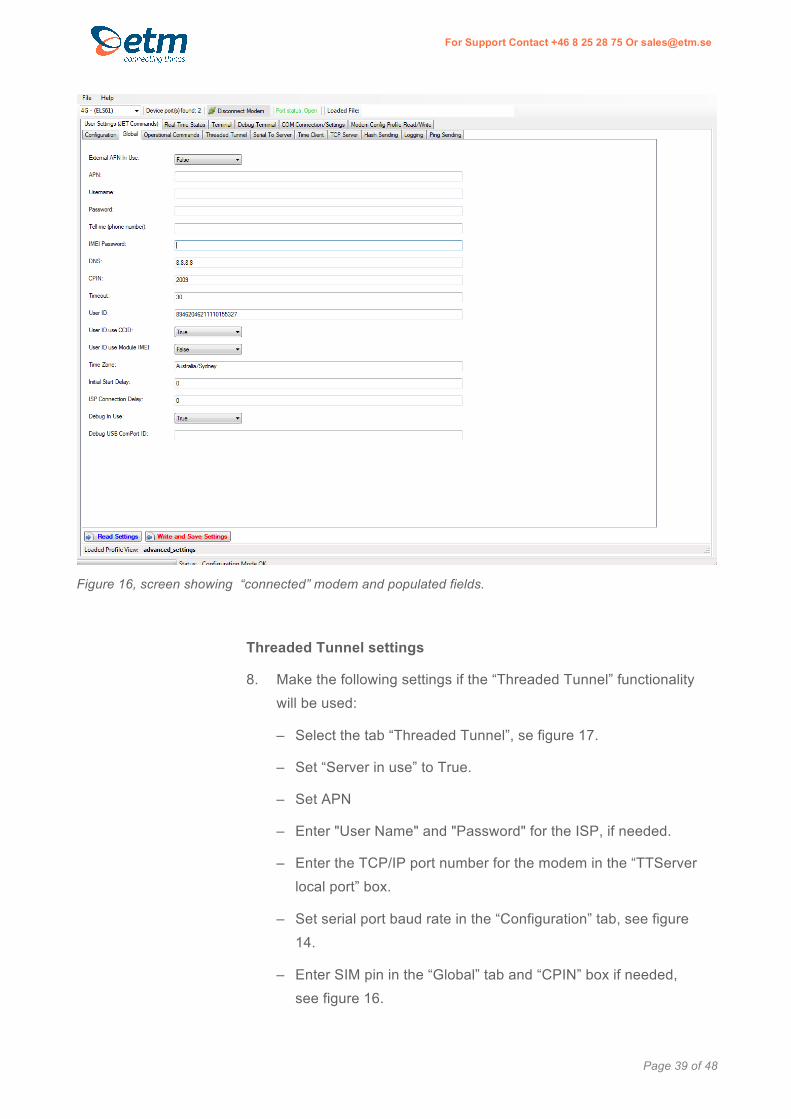
Figure 16, screen showing “connected” modem and populated fields.
Threaded Tunnel settings
8. Make the following settings if the “Threaded Tunnel” functionality will be used:
– Select the tab “Threaded Tunnel”, se figure 17.
– Set “Server in use” to True.
– Set APN
– Enter "User Name" and "Password" for the ISP, if needed.
– Enter the TCP/IP port number for the modem in the “TTServer local port” box.
– Set serial port baud rate in the “Configuration” tab, see figure 14.
– Enter SIM pin in the “Global” tab and “CPIN” box if needed, see figure 16.

Page 40 of 48
For Support Contact +46 8 25 28 75 Or [email protected]
Click WRITE AND SAVE SETTINGS.
The changed data will be written into the memory of the ETM-Purple modem.
Figure 17, screen showing the “Threaded Tunnel” settings.
9. Select the “Real Time Status” tab. The following screen will
appear:

Page 41 of 48
For Support Contact +46 8 25 28 75 Or [email protected]
Figure 18, screen showing “Real Time Status”.
The “Real Time Status” screen shows useful information about the mobile
network, software, hardware and data-exchange parameters. This screen is
updated every 15 seconds which is adjustable.
These parameters can be saved to the local computer by pressing the “Save
RTS Report”
10. Select the “Terminal” tab. The following screen will appear:
Page 42 of 48
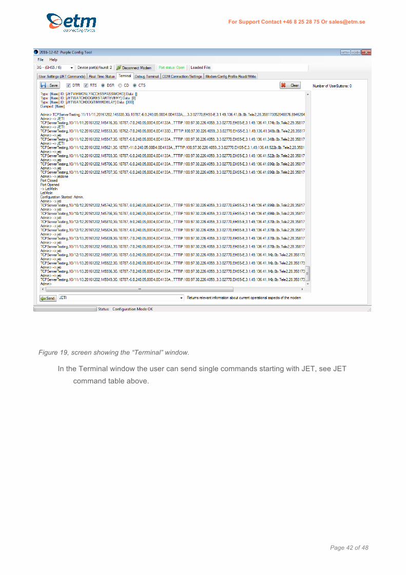
For Support Contact +46 8 25 28 75 Or [email protected]
Figure 19, screen showing the “Terminal” window.
In the Terminal window the user can send single commands starting with JET, see JET
command table above.

Page 43 of 48
For Support Contact +46 8 25 28 75 Or [email protected]
11. Select the “Debug Terminal” tab. The following screen will
appear:
Figure 20, screen showing the “Debug Terminal” window.
This screen shows the activity in the modem and can be useful to fault trace
problems in the field. The debug log shows activity since the start of the ETM-
Purple Configuration Tool. The log file can be saved to the local computer by
pressing the “Save” button.

Page 44 of 48
For Support Contact +46 8 25 28 75 Or [email protected]
12. Select the “COM Connection/settings” tab. The following screen
will appear

Page 45 of 48
For Support Contact +46 8 25 28 75 Or [email protected]
Figure 21, screen showing the “COM Connection” window.
The USB port settings and the ETM-Purple Configuration Tool password can be changed in
this screen.
Note that the modem connection to the computer can stop working if changes are made in this screen.
Figure 22, screen showing the “File” menu.

Page 46 of 48
For Support Contact +46 8 25 28 75 Or [email protected]
13. Select “Read & Save Script file from Modem” to save the
complete modem configuration for backup or in order to copy the
configuration to other ETM-Purple modems.
14. Select “Load & Execute Script file to configure Modem” to open a
saved modem configuration and load it to the modem.
15. Disconnect the modem by clicking on the “Disconnect Modem”.
* Always disconnect before unplugging otherwise the device may not
be recognized or port may be stuck.
16. Unplug the ETM programming USB cable from the ETM-Purple
modem and computer.

Page 47 of 48
For Support Contact +46 8 25 28 75 Or [email protected]
This page intentionally left blank

ETM Matteknik AB
Ekbacksvägen 32
SE-168 69 Bromma
Sweden
Tel: +46 (0)8 25 28 75
Fax: +46 (0)8 80 11 10
Email: [email protected]
Web: www.etm.se
ETM Pacific Pty Ltd
Suite, 273 Alfred Street
North Sydney NSW 2060
Australia
Tel: +61 (0)2 9956 7377
Fax: +61 (0)2 9956 5791
Email: [email protected]
Web: www.etmpacific.com.au
© ETM · Subject to change without notice.
Related Documents