THERMAL POWER PLANT Coal to Electricity

Welcome message from author
This document is posted to help you gain knowledge. Please leave a comment to let me know what you think about it! Share it to your friends and learn new things together.
Transcript
THERMAL POWER PLANT
Coal to Electricity
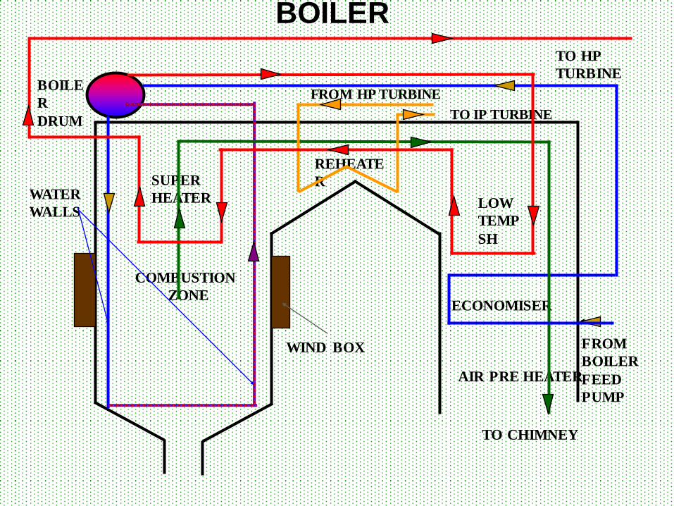
ECONOMISER
LOW
TEMP
SH
REHEATE
R SUPER
HEATER
COMBUSTION
ZONE
AIR PRE HEATER
BOILE
R
DRUM
WATER
WALLS
WIND BOX FROM
BOILER
FEED
PUMP
TO HP
TURBINE
FROM HP TURBINE
TO IP TURBINE
TO CHIMNEY
BOILER
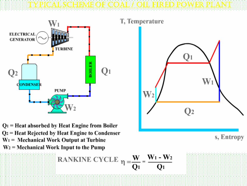
TYPICAL SCHEME OF COAL / OIL FIRED POWER PLANT
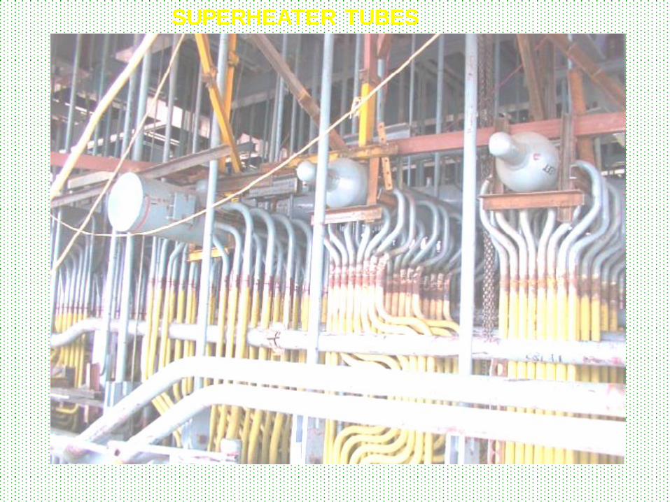
SUPERHEATER TUBES

REHEATER PANEL
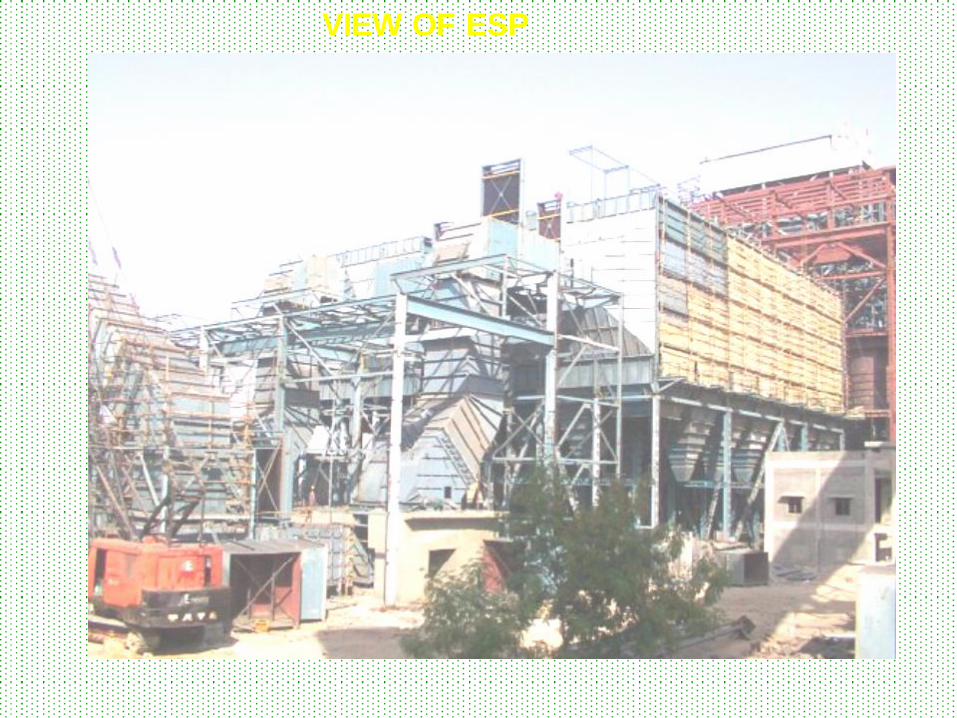
VIEW OF ESP
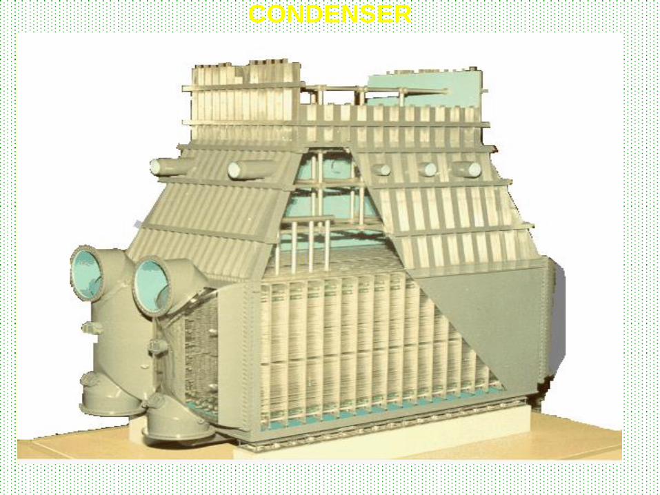
CONDENSER

BOILER
Condenser
LP
TURBINE
IP
TURBINE
HP
TURBINE
MS
MS
CRH
NRV
HRH
HPSV
HPSV
IPSV
IPSV GENERATOR
HPCV
HPCV
IPCV
IPCV
CRH
NRV
TG SET
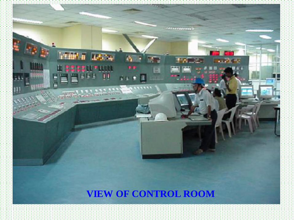
VIEW OF CONTROL ROOM
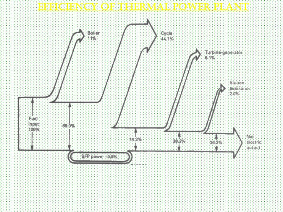
EFFICIENCY OF THERMAL POWER PLANT
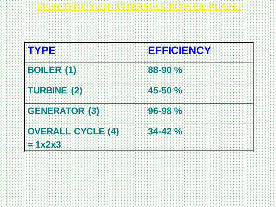
TYPE EFFICIENCY
BOILER (1) 88-90 %
TURBINE (2) 45-50 %
GENERATOR (3) 96-98 %
OVERALL CYCLE (4)
= 1x2x3
34-42 %
EFFICIENCY OF THERMAL POWER PLANT
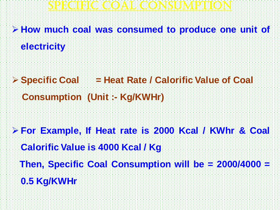
How much coal was consumed to produce one unit of
electricity
Specific Coal = Heat Rate / Calorific Value of Coal
Consumption (Unit :- Kg/KWHr)
For Example, If Heat rate is 2000 Kcal / KWhr & Coal
Calorific Value is 4000 Kcal / Kg
Then, Specific Coal Consumption will be = 2000/4000 =
0.5 Kg/KWHr
Specific coal consumption
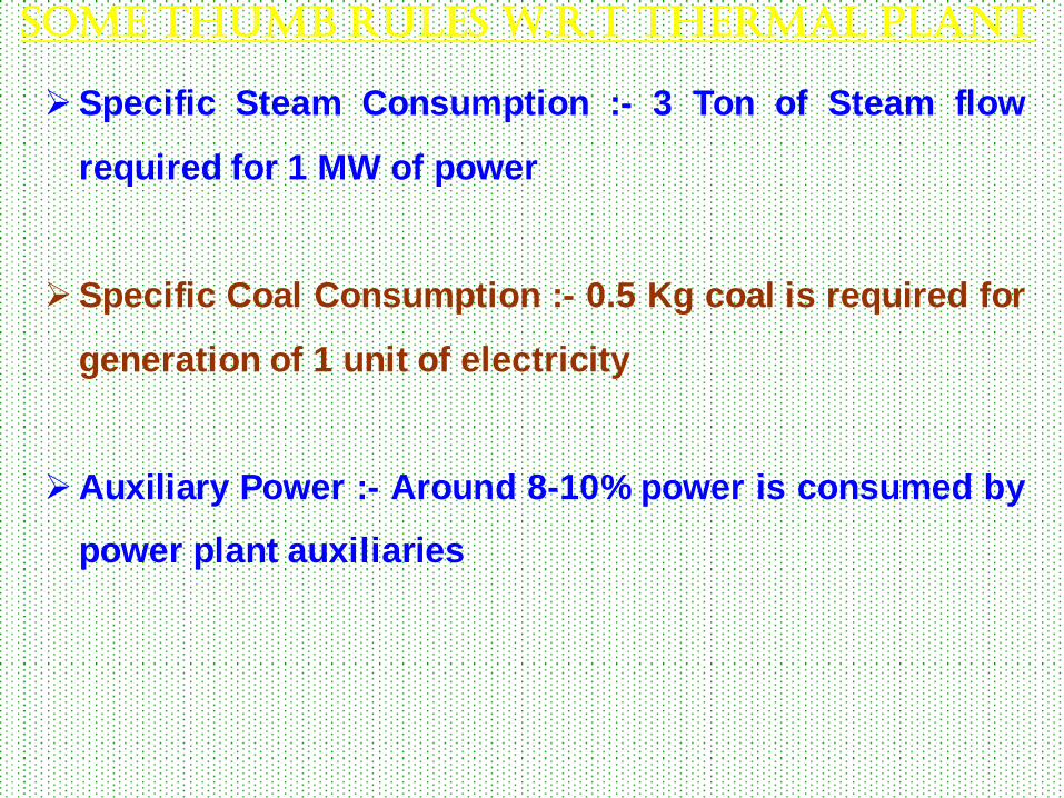
Specific Steam Consumption :- 3 Ton of Steam flow
required for 1 MW of power
Specific Coal Consumption :- 0.5 Kg coal is required for
generation of 1 unit of electricity
Auxiliary Power :- Around 8-10% power is consumed by
power plant auxiliaries
Some thumb rules w.r.t thermal plant

Efficiency of Thermal power ranges from 33 to 40 %
One 500 MW thermal power plant generates 12 million
units of electricity daily
Around 22000 TO 69000 m3/hr of water is required for
condensing steam in Condenser for a 210 TO 660 MW
Each power station has to maintain stock of minimum 7
days (Critical Stock)
Some thumb rules w.r.t thermal plant
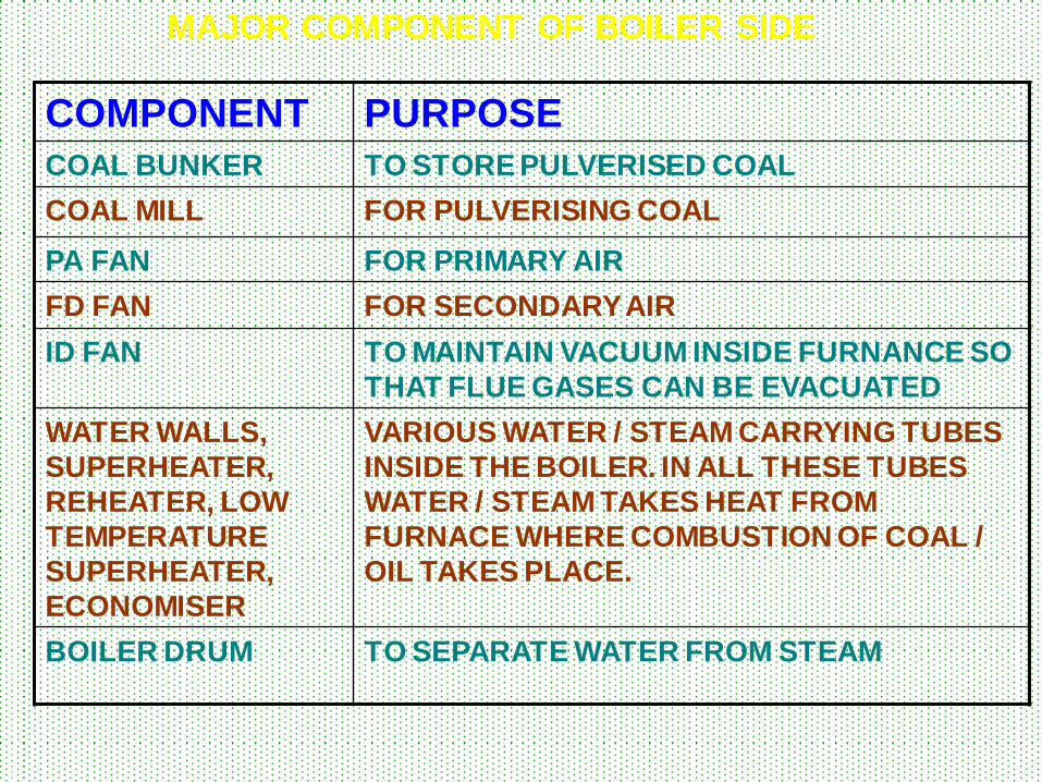
MAJOR COMPONENT OF BOILER SIDE
COMPONENT PURPOSE
COAL BUNKER TO STORE PULVERISED COAL
COAL MILL FOR PULVERISING COAL
PA FAN FOR PRIMARY AIR
FD FAN FOR SECONDARY AIR
ID FAN TO MAINTAIN VACUUM INSIDE FURNANCE SO
THAT FLUE GASES CAN BE EVACUATED
WATER WALLS,
SUPERHEATER,
REHEATER, LOW
TEMPERATURE
SUPERHEATER,
ECONOMISER
VARIOUS WATER / STEAM CARRYING TUBES
INSIDE THE BOILER. IN ALL THESE TUBES
WATER / STEAM TAKES HEAT FROM
FURNACE WHERE COMBUSTION OF COAL /
OIL TAKES PLACE.
BOILER DRUM TO SEPARATE WATER FROM STEAM
COAL AND
COMBUSTION
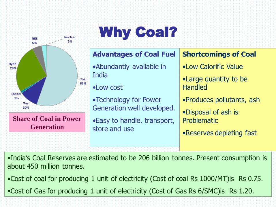
Why Coal?
Share of Coal in Power
Generation
Advantages of Coal Fuel
•Abundantly available in India
•Low cost
•Technology for Power Generation well developed.
•Easy to handle, transport, store and use
Shortcomings of Coal
•Low Calorific Value
•Large quantity to be Handled
•Produces pollutants, ash
•Disposal of ash is Problematic
•Reserves depleting fast
•India’s Coal Reserves are estimated to be 206 billion tonnes. Present consumption is about 450 million tonnes.
•Cost of coal for producing 1 unit of electricity (Cost of coal Rs 1000/MT)is Rs 0.75.
•Cost of Gas for producing 1 unit of electricity (Cost of Gas Rs 6/SMC)is Rs 1.20.
Coal
55%
Gas
10%
Diesel
1%
Hydel
26%
RES
5%
Nuclear
3%
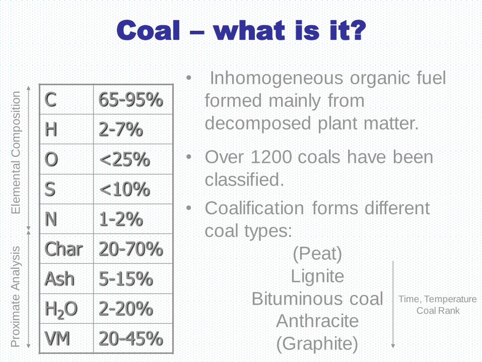
Coal – what is it?
65-95% C
2-7% H
<25% O
<10% S
1-2% N
20-70% Char
5-15% Ash
2-20% H2O
20-45% VM
• Inhomogeneous organic fuel
formed mainly from
decomposed plant matter.
• Over 1200 coals have been
classified.
Time, Temperature
Coal Rank
• Coalification forms different
coal types:
(Peat)
Lignite
Bituminous coal
Anthracite
(Graphite)
Pro
xim
ate
An
aly
sis
E
lem
en
tal C
om
positio
n
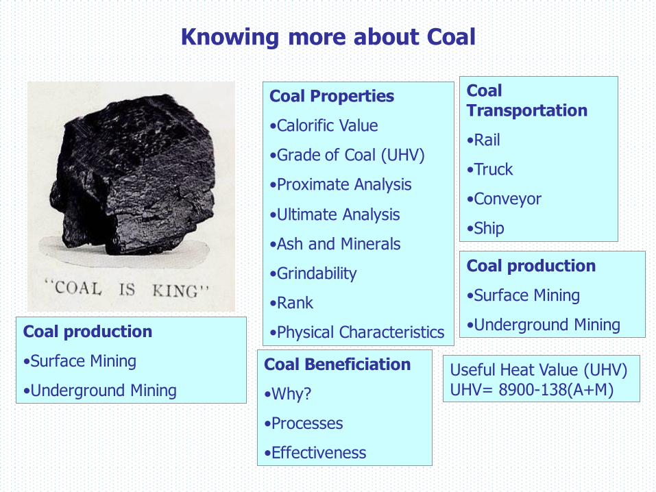
Knowing more about Coal
Coal Transportation
•Rail
•Truck
•Conveyor
•Ship
Coal production
•Surface Mining
•Underground Mining
Coal Properties
•Calorific Value
•Grade of Coal (UHV)
•Proximate Analysis
•Ultimate Analysis
•Ash and Minerals
•Grindability
•Rank
•Physical Characteristics
Coal Beneficiation
•Why?
•Processes
•Effectiveness
Coal production
•Surface Mining
•Underground Mining
Useful Heat Value (UHV) UHV= 8900-138(A+M)

Coal Applications
• Homes – heat and cooking
• Transportation – steam
engines
• Industry – metal works
• Electricity – power plants
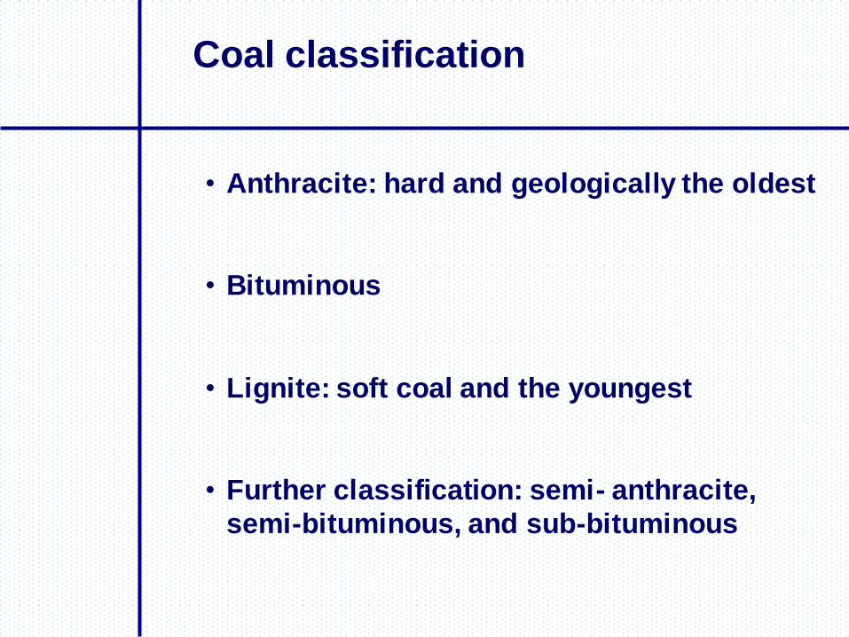
Coal classification
• Anthracite: hard and geologically the oldest
• Bituminous
• Lignite: soft coal and the youngest
• Further classification: semi- anthracite,
semi-bituminous, and sub-bituminous

24
Physical properties
• Heating or calorific value (GCV)
• Moisture content
• Volatile matter
• Ash
Chemical properties
• Chemical constituents: carbon, hydrogen, oxygen, sulphur
Coal Properties

25
Heating or calorific value
• The typical GVCs for various coals are:
Parameter Lignite
(Dry
Basis)
Indian
Coal
Indonesian
Coal
South
African
Coal
GCV
(kCal/kg)
4,500 4,000 5,500 6,000
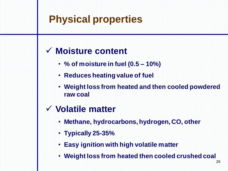
Physical properties
26
Moisture content
• % of moisture in fuel (0.5 – 10%)
• Reduces heating value of fuel
• Weight loss from heated and then cooled powdered
raw coal
Volatile matter
• Methane, hydrocarbons, hydrogen, CO, other
• Typically 25-35%
• Easy ignition with high volatile matter
• Weight loss from heated then cooled crushed coal
Physical properties
27
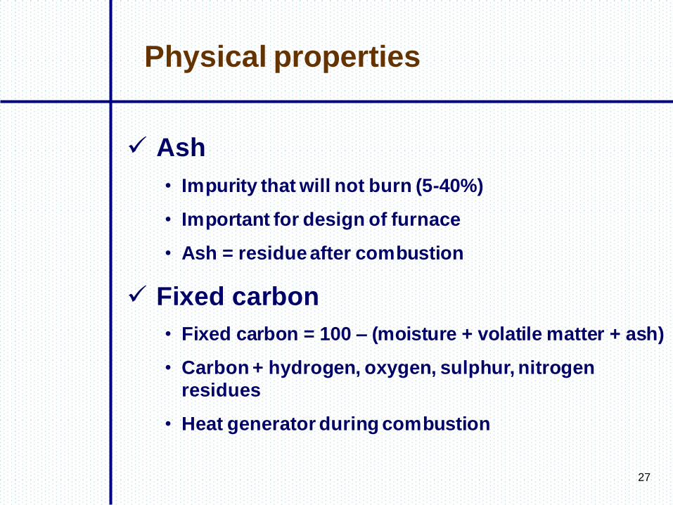
Ash
• Impurity that will not burn (5-40%)
• Important for design of furnace
• Ash = residue after combustion
Fixed carbon
• Fixed carbon = 100 – (moisture + volatile matter + ash)
• Carbon + hydrogen, oxygen, sulphur, nitrogen
residues
• Heat generator during combustion
Physical properties

28
Proximate analysis of coal
• Determines only fixed carbon, volatile matter,
moisture and ash
• Useful to find out heating value (GCV)
• Simple analysis equipment
Ultimate analysis of coal
• Determines all coal component elements: carbon,
hydrogen, oxygen, sulphr, other
• Useful for furnace design (e.g. flame temperature,
flue duct design)
• Laboratory analysis
Analysis of Coal
29
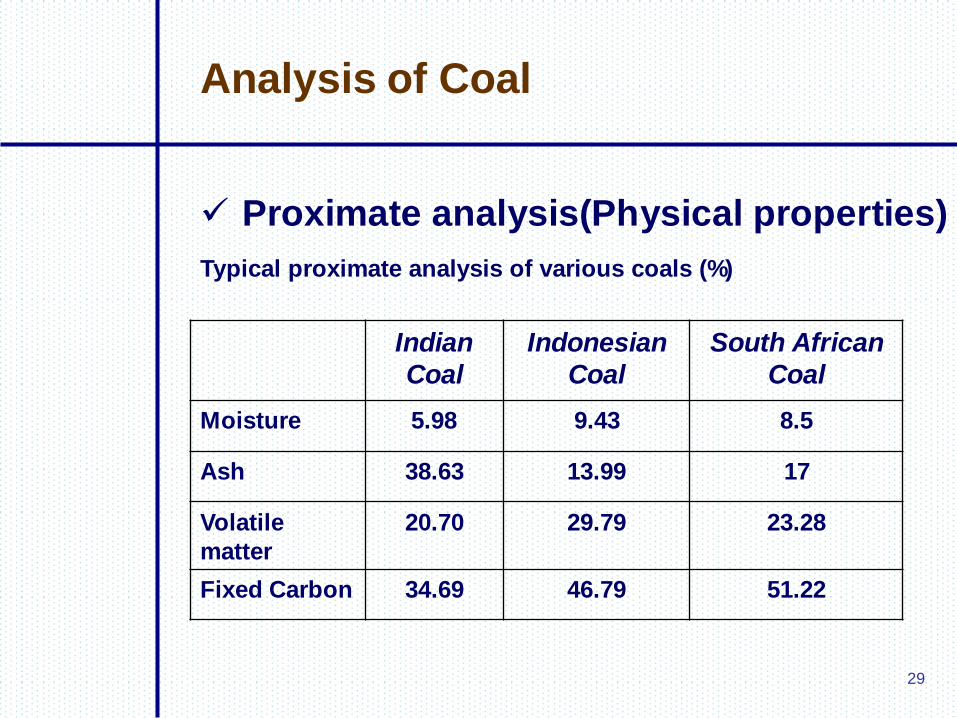
Analysis of Coal
Proximate analysis(Physical properties)
Typical proximate analysis of various coals (%)
Indian
Coal
Indonesian
Coal
South African
Coal
Moisture 5.98 9.43 8.5
Ash 38.63 13.99 17
Volatile
matter
20.70 29.79 23.28
Fixed Carbon 34.69 46.79 51.22
30
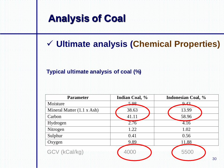
Analysis of Coal
Ultimate analysis (Chemical Properties)
Typical ultimate analysis of coal (%)
Parameter Indian Coal, % Indonesian Coal, %
Moisture 5.98 9.43
Mineral Matter (1.1 x Ash) 38.63 13.99
Carbon 41.11 58.96
Hydrogen 2.76 4.16
Nitrogen 1.22 1.02
Sulphur 0.41 0.56
Oxygen 9.89 11.88
GCV (kCal/kg) 4000 5500

31
Performance Evaluation
• Combustion: rapid oxidation of a fuel
• Complete combustion: total oxidation of fuel (adequate supply of oxygen needed)
• Air: 23.2% oxygen, 76% nitrogen and other
• Nitrogen: (a) reduces the combustion efficiency (b) forms
NOx at high temperatures
• Carbon forms (a) CO2 (b) CO resulting in less heat
production
Principles of Combustion
32
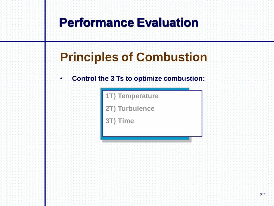
Performance Evaluation
• Control the 3 Ts to optimize combustion:
Principles of Combustion
1T) Temperature
2T) Turbulence
3T) Time

33
Performance Evaluation
Oxygen is the key to combustion
Principle of Combustion
Bureau of Energy Efficiency, India, 2004

34
Performance Evaluation
Stoichiometric calculation of air
required
Stoichiometric air needed for combustion of furnace oil
Theoretical CO2 content in the flue gases
Actual CO2 content and % excess air
Constituents of flue gas with excess air
Theoretical CO2 and O2 in dry flue gas by volume
35
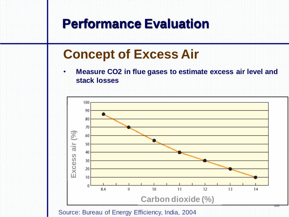
Performance Evaluation
• Measure CO2 in flue gases to estimate excess air level and
stack losses
Concept of Excess Air
Carbon dioxide (%)
Excess a
ir (
%)
Source: Bureau of Energy Efficiency, India, 2004
36
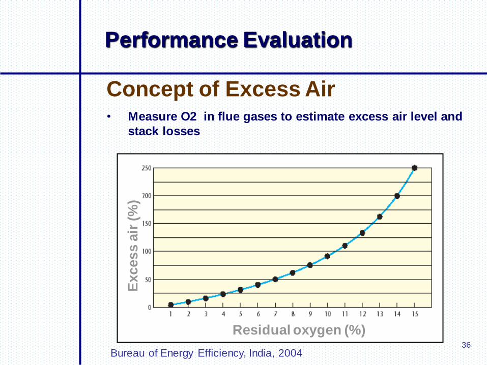
Performance Evaluation
Concept of Excess Air
Residual oxygen (%)
Excess a
ir (%
)
Bureau of Energy Efficiency, India, 2004
• Measure O2 in flue gases to estimate excess air level and
stack losses
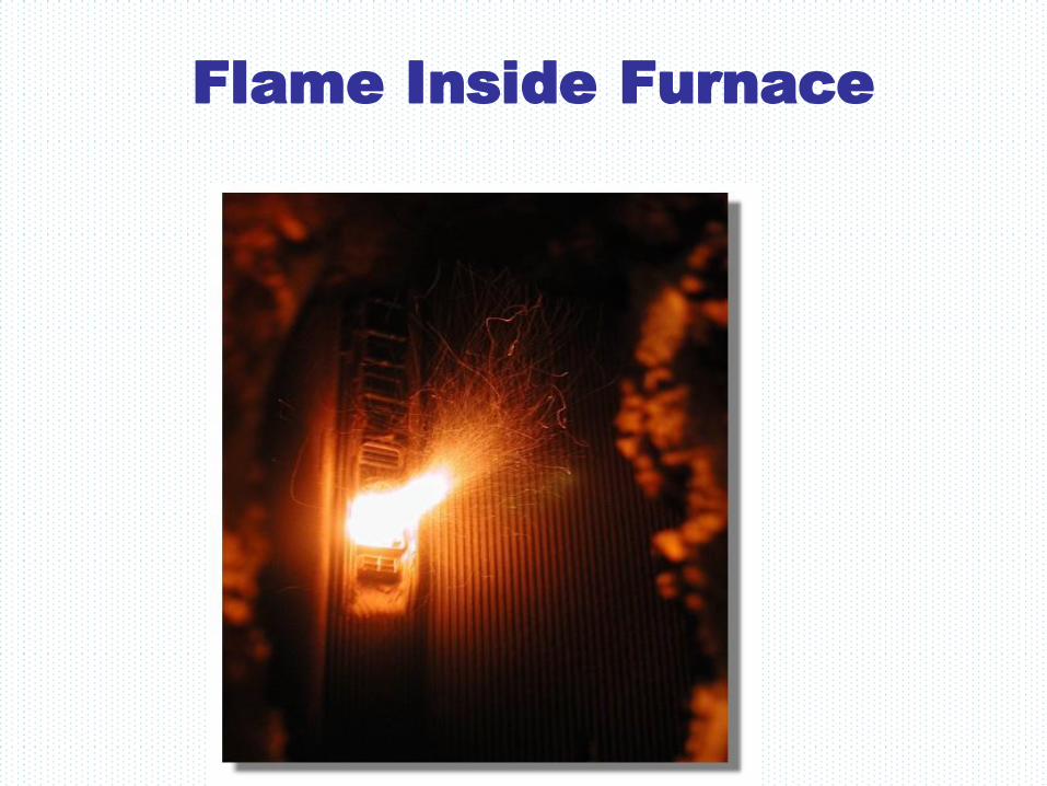
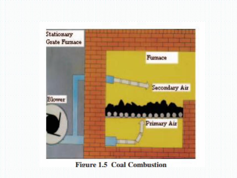
Flame Inside Furnace
Fuel Burning furnaces
• Furnace provide controlled, efficient conversion of chemical energy of
fuel into heat energy which is transferred to the heat absorbing surfaces
of the steam generator.
• The firing system introduce the fuel and air for combustion, mix these
reactants, ignite the mixture and distribute the flame and combustion.
• Furnace can be divided into two types:
a. Grate-fired furnaces
b. Chamber-type or flame furnace
Combustion Equipment's
Coal may be fed into furnace for combustion in lump pieces or in
powder form.
a. Fuel bed furnaces (for coarse particles)
b. Pulverized coal furnaces (fine particles)
c. Cyclone furnaces (crushed particles)
d. Fluidized bed furnaces (crushed small particles)
Fuel bed combustion
A grate is used at furnace bottom to hold a bed of fuel. There are two ways of
feeding coal on to the grate:
a. Overfeeding
b. Underfeeding
In overfeeding, the coal is fed into the grate above the point of air admission
and in case of underfeeding, the coal is admitted into the furnace below the
point of air admission.
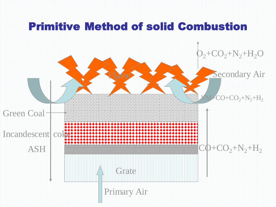
Primitive Method of solid Combustion
Primary Air
Secondary Air Flame
Green Coal
Incandescent coke
Grate
CO+CO2+N2+H2
VM+CO+CO2+N2+H2
O2+CO2+N2+H2O
ASH
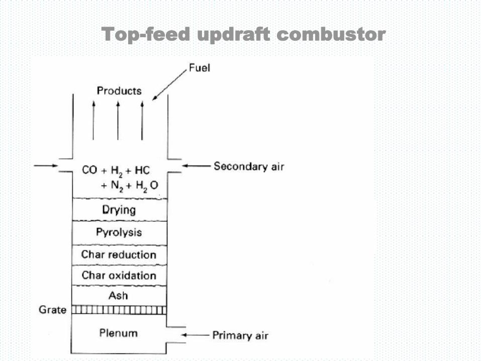
Top-feed updraft combustor
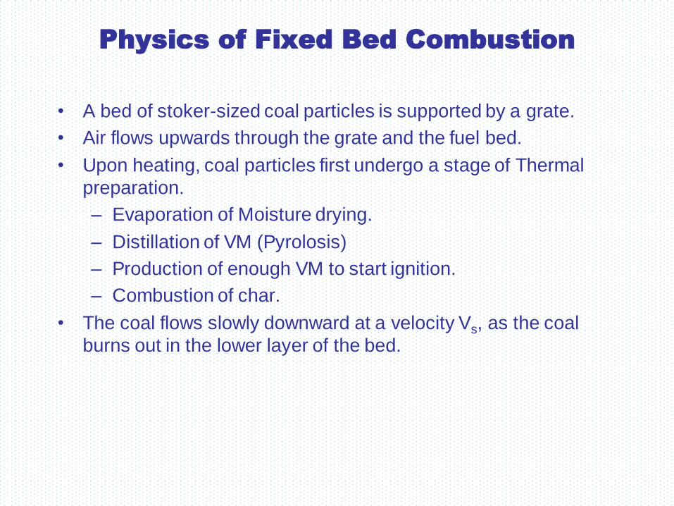
Physics of Fixed Bed Combustion
• A bed of stoker-sized coal particles is supported by a grate.
• Air flows upwards through the grate and the fuel bed.
• Upon heating, coal particles first undergo a stage of Thermal
preparation.
– Evaporation of Moisture drying.
– Distillation of VM (Pyrolosis)
– Production of enough VM to start ignition.
– Combustion of char.
• The coal flows slowly downward at a velocity Vs, as the coal
burns out in the lower layer of the bed.

Overfeed and underfeed fuel bed
section
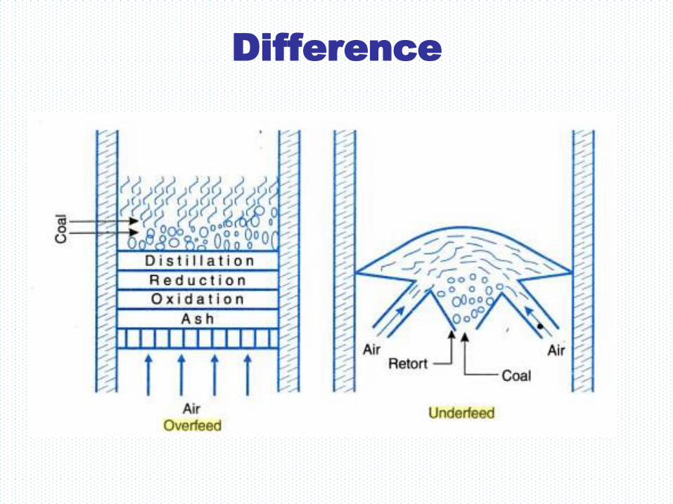
Difference
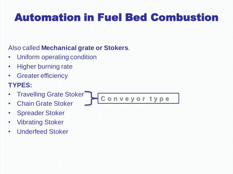
Automation in Fuel Bed Combustion
Also called Mechanical grate or Stokers.
• Uniform operating condition
• Higher burning rate
• Greater efficiency
TYPES:
• Travelling Grate Stoker
• Chain Grate Stoker
• Spreader Stoker
• Vibrating Stoker
• Underfeed Stoker
C o n v e y o r t y p e
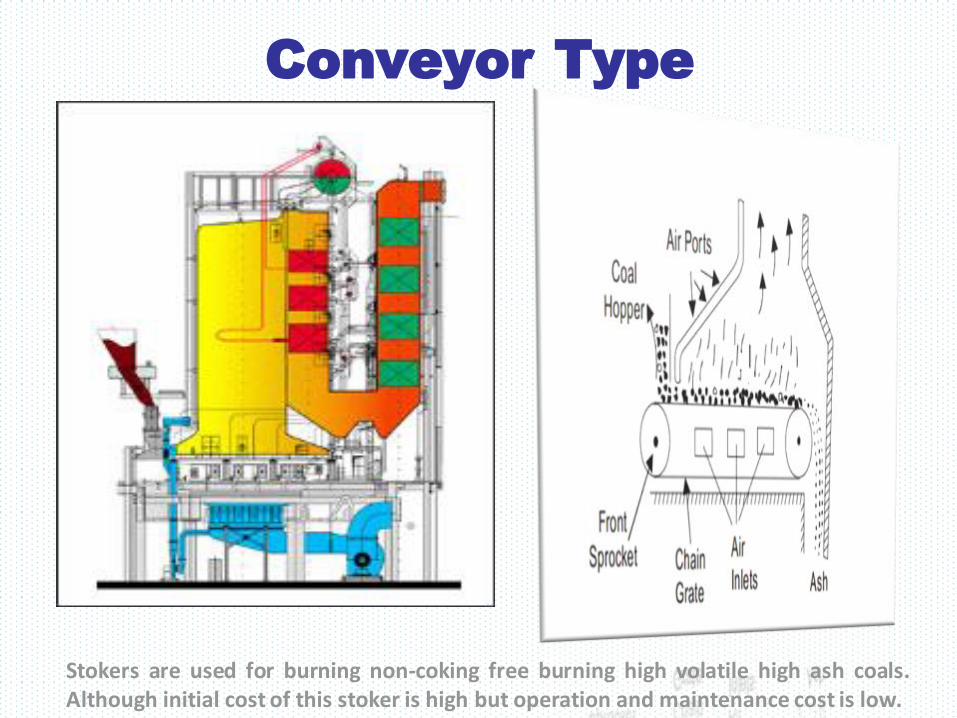
Conveyor Type
Stokers are used for burning non-coking free burning high volatile high ash coals. Although initial cost of this stoker is high but operation and maintenance cost is low.

Spreader Stoker

Spreader Stoker
Advantages • Its operation cost is low.
• A wide variety of coal can be burnt easily by this stoker.
• A thin fuel bed on the grate is helpful in meeting the fluctuating loads.
• Ash under the fire is cooled by the incoming air and this minimizes
clinkering.
• The fuel burns rapidly and there is little coking with coking fuels.
Disadvantages • The spreader does not work satisfactorily with varying size of coal.
• In this stoker the coal burns in suspension and due to this fly ash is
discharged with flue gases which requires an efficient dust collecting
equipment.

Underfeed stoker

Closing Remarks on Mechanical
stokers
• In all MS forced draft fans are used both for PA and over fire SA.
• A practical engineering limit seems to be reached when the
length and width of the grate are about 9 m with grate area 80
m2.
• In practice stokers have rarely exceeded a capacity of 135
tons/hour.
• Heat release rate-1340 kW/m2
• Stoker firing is limited to relatively low capacity up to 50 kg/s of
steam due to low efficiency. However, in their size range (19 to
32 mm) stokers remains important in steam generator system.
• Beyond a certain size of boiler, stokers become impracticable
and uneconomical (increase floor area).
Pulverized Fuel Combustion
• Invented in 1920.
• Fine particles of coal ~ 75 microns.
• Huge heat release per unit area : 2 – 5 MW/m2.
• Steam generation : 2000 tons/hour.


Schematic of typical coal pulverized
system
A Inlet Duct;
B Bowl Orifice;
C Grinding Mill;
D Transfer Duct to Exhauster;
E Fan Exit Duct.
Ash disposal
• A large quantity of ash is, produced in steam power plants using coal.
• Ash produced in about 10 to 20% of the total coal burnt in the furnace.
• Handling of ash is a problem because ash coming out of the furnace is too hot, it is dusty and irritating to handle and is accompanied by some poisonous gases.
• It is desirable to quench the ash before handling due to following reasons:
1. Quenching reduces the temperature of ash.
2. It reduces the corrosive action of ash.
3. Ash forms clinkers by fusing in large lumps and by quenching clinkers will
disintegrate.
4. Quenching reduces the dust accompanying the ash.
Types of Ash
• Burning of Coal leads to generation of Ash
• Can be the non- combustible part of fuel, or
generated after the burning of the coal
• Two Types are :-
• Bottom Ash
• Fly Ash

Bottom Ash
• Non- Combustible Part of Combustion
• Comprises traces of combustibles embedded in
forming clinkers and sticking to hot side walls of a
coal-burning furnace
• The clinkers fall by themselves into the water or
sometimes by poking manually, and get cooled
• May be used as an aggregate in road construction
and concrete
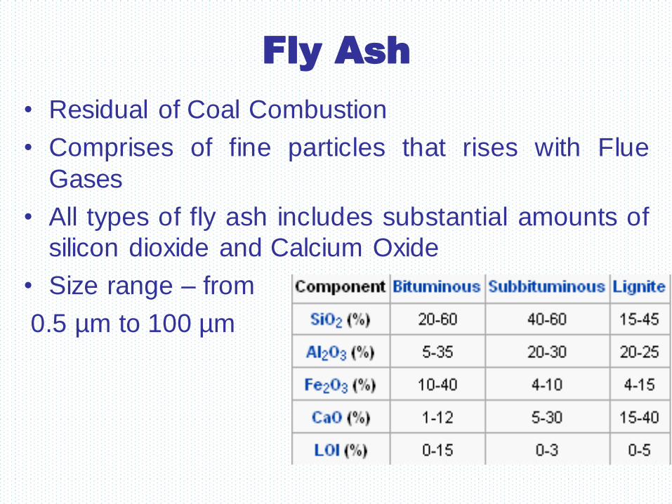
Fly Ash
• Residual of Coal Combustion
• Comprises of fine particles that rises with Flue
Gases
• All types of fly ash includes substantial amounts of
silicon dioxide and Calcium Oxide
• Size range – from
0.5 µm to 100 µm
Challenges of Ash handling
• Indian coal presents high ash content generally
which tends to be inconsistent. Design of the
system has to adequately cover anticipated
variations and be capable of handling the worst
scenario.
• System has to be environmentally friendly.
• System has to be reliable with least maintenance
problems.
• System has to be energy efficient
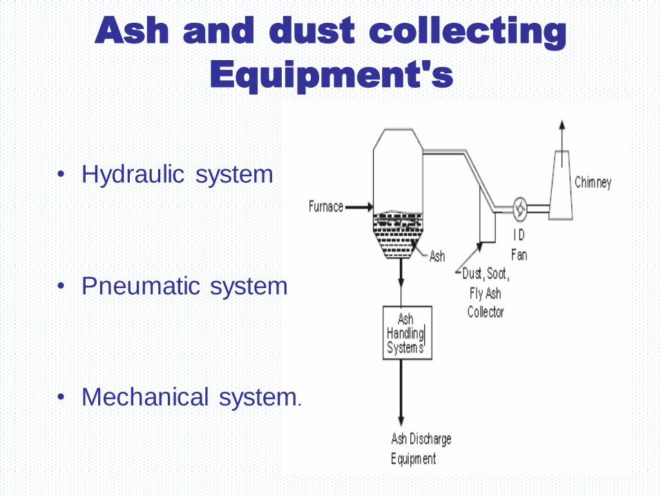
Ash and dust collecting
Equipment's
• Hydraulic system
• Pneumatic system
• Mechanical system.

Dust collection system
The size of dust particles is designated in microns (1 μ = 0.001 mm). Dust particles are mainly
ash particles called fly ash intermixed with some quantity of carbon ash material called cinders.
Gas borne particles larger than 1μ in diameter are called dust and when such particles become
greater in size than 100µ they are called cinders. Smoke is produced due to the incomplete
combustion of fuels, smoke particles are less than 10µ in size.
The disposal smoke to the atmosphere is not desirable due to the following reasons :
1. A smoky atmosphere is less healthful than smoke free air.
2. Smoke is produced due to incomplete combustion of coal. This will create a big economic
loss due to loss of heating value of coal.
3. In a smoky atmosphere lower standards of cleanliness are prevalent. Buildings, clothing's,
furniture etc. becomes dirty due to smoke. Smoke corrodes the metals and darkens the paints.
To avoid smoke nuisance the coal should be completely burnt in the furnace.

Types of dust collectors
The various types of dust collectors are as follows :
1. Mechanical dust collectors.
2. Electrical dust collectors.
Mechanical dust collectors. Mechanical dust collectors are sub-divided into wet and dry types.
In wet type collectors also known as scrubbers water sprays are used to wash dust from the air.
The basic principles of mechanical dust collectors are shown in Fig. As shown in Fig. by
increasing the cross-sectional area of duct through which dust laden gases are passing, the
velocity of gases is reduced and causes heavier dust particles to fall down. Changing the direction
of flow of flue gases causes the heavier particles of settle out. Sometime baffles are provided as
to separate the heavier particles. Mechanical dust collectors may be wet type or dry type. Wet
type dust collectors called scrub scrubbers make use of water sprays to wash the dust from flue gases.
Dry type dust collectors include gravitational, cyclone, and baffle dust collectors.
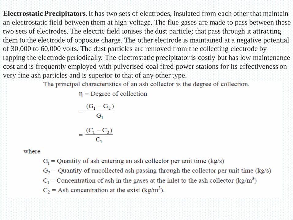
Electrostatic Precipitators. It has two sets of electrodes, insulated from each other that maintain
an electrostatic field between them at high voltage. The flue gases are made to pass between these
two sets of electrodes. The electric field ionises the dust particle; that pass through it attracting
them to the electrode of opposite charge. The other electrode is maintained at a negative potential
of 30,000 to 60,000 volts. The dust particles are removed from the collecting electrode by
rapping the electrode periodically. The electrostatic precipitator is costly but has low maintenance
cost and is frequently employed with pulverised coal fired power stations for its effectiveness on
very fine ash particles and is superior to that of any other type.
4.13.1 FLY ASH SCRUBBER
It is similar to a mechanical ash collector but has a flowing water film on its inner walls. Due to
this film, the collected ash is removed more rapidly from the apparatus to the bin. The degree of
ash collection in scrubbers varies from 0.82 to 0.90. The dust laden gas enters through the inlet
pipe.
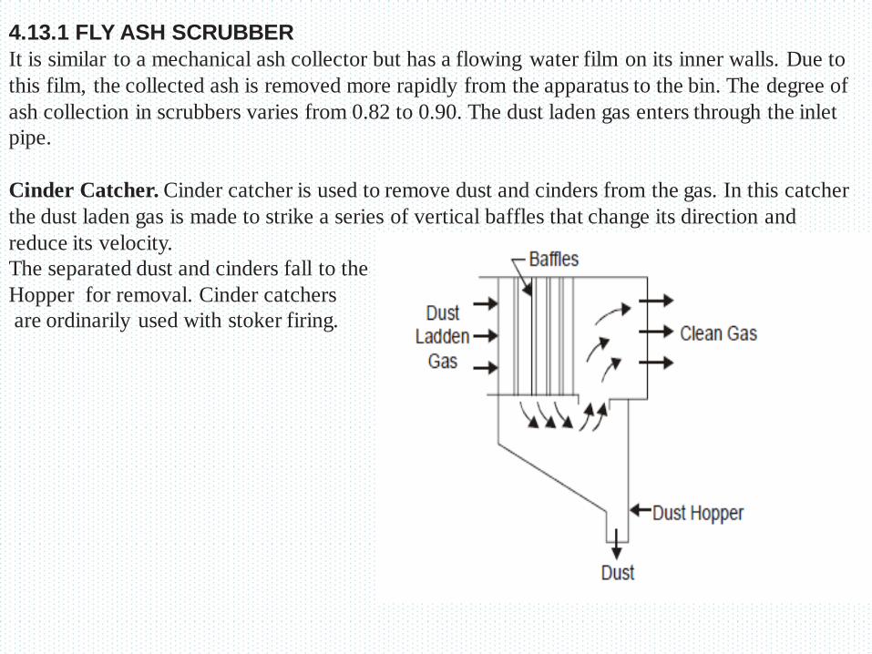
Cinder Catcher. Cinder catcher is used to remove dust and cinders from the gas. In this catcher
the dust laden gas is made to strike a series of vertical baffles that change its direction and
reduce its velocity.
The separated dust and cinders fall to the
Hopper for removal. Cinder catchers
are ordinarily used with stoker firing.
Related Documents


