Manual No. 165-31590 INSTALLATION, OPERATION AND MAINTENANCE INSTRUCTIONS FOR BAYLOR EDDY CURRENT BRAKE, MODEL 6032 EQUIPMENT FURNISHED BY National Oilwell 500 INDUSTRIAL BLVD. SUGAR LAND TEXAS 77478-2898 TELEPHONE: (281) 240-6111 FAX: (281) 240-0426 Rev. D 02/11/02

Welcome message from author
This document is posted to help you gain knowledge. Please leave a comment to let me know what you think about it! Share it to your friends and learn new things together.
Transcript
Manual No. 165-31590
INSTALLATION, OPERATION AND MAINTENANCE INSTRUCTIONS FOR
BAYLOR EDDY CURRENT BRAKE, MODEL 6032
EQUIPMENT FURNISHED BY
National Oilwell 500 INDUSTRIAL BLVD.
SUGAR LAND TEXAS 77478-2898 TELEPHONE: (281) 240-6111
FAX: (281) 240-0426
Rev. D
02/11/02
SAFETY FIRST! Before placing this equipment in operation, certain basic rules of safety should be observed. It should be noted that no safety rules and no amount of safety equipment will make operating this equipment safe, unless the operator enforces the rules and proper uses of the equipment.
MACHINE OPERATION: 1. Only responsible persons, trained to do so, should operate this equipment. 2. Any person operating this equipment should be thoroughly familiar with the manufacturer's
recommended operating instructions.
CLEANLINESS AND SERVICE 1. Periodic cleaning of the equipment may reveal potential mechanical trouble spots such as loose
or missing bolts, fittings, etc.. 2. Keep the area around the equipment clear of loose tools, trash, extraneous matter, etc.. 3. Shut the equipment down before servicing or cleaning unless the service work requires the
equipment be operating. 4. Allow only an experienced mechanic to service the equipment. 5. If a mechanical problem or deficiency is found, correct or report it before continuing operation. 6. Before working under or between components that are suspended by hoists or slings, securely
block or crib them. 7. When working in an area of potential head injury, wear an approved safety helmet.
CAUTION! MANY PARTS ARE HEAVY OR DIFFICULT TO HANDLE.
PLAN LIFTS AND MOVES CAREFULLY TO AVOID SEVERE PERSONAL INJURY. PROVIDE SAFE SUPPORTS FOR
DISASSEMBLED PARTS.
i
Table of Contents
Section 1 Introduction and Description 1.1 Scope of Manual .................................................................................................................. 1-1 1.2 General Description of Equipment ....................................................................................... 1-1
Section 2 Summery of Specification 2.1 Specifications....................................................................................................................... 2-1
Section 3 Installation 3.1 General ................................................................................................................................ 3-1 3.2 Brake Alignment .................................................................................................................. 3-6 3.3 Shaft Alignment ................................................................................................................... 3-6 3.4 Cooling Water Quality .......................................................................................................... 3-7 3.4.1 Scope....................................................................................................................... 3-7 3.4.2 Water Quality Standards .......................................................................................... 3-7 3.4.3 Corrosion Inhibitor.................................................................................................... 3-7 3.4.4 Usage of Antifreeze Standards ................................................................................ 3-8 3.5 Cooling System Capacity Calculation .................................................................................. 3-8 3.6 Brake Field Coil Polarity..................................................................................................... 3-10 3.7 Certification for Hazardous Location.................................................................................. 3-14
Section 4 Theory of Operation 4.1 General ................................................................................................................................ 4-1 4.2 Brake Operation on Rig ....................................................................................................... 4-1 4.2.1 Drill Assist Operation................................................................................................ 4-2
Section 5 Accessories and Options 5.1 General ................................................................................................................................ 5-1 5.1.1 Brake Controller ....................................................................................................... 5-1 5.1.2 Special Brake Shafts................................................................................................ 5-1 5.1.3 Brake Cooling Packages.......................................................................................... 5-1 5.1.4 Cooling Water Alarm................................................................................................ 5-1 5.1.5 Safety Monitoring Device ......................................................................................... 5-1 5.1.6 Parts and Service..................................................................................................... 5-2
ii
Section 6 Maintenance and Service 6.1 General ................................................................................................................................ 6-1 6.1.1 Lubrication................................................................................................................ 6-1 6.1.2 Breather ................................................................................................................... 6-1 6.1.3 Air Gap..................................................................................................................... 6-1 6.1.4 Overflow Outlet ........................................................................................................ 6-2 6.1.5 Water Outlet Drain ................................................................................................... 6-2 6.1.6 Preparation of Brake for Storage ............................................................................. 6-3 6.1.7 Removing a Brake from Storage.............................................................................. 6-3 6.2 Maintenance and Repair...................................................................................................... 6-4 6.2.1 Water System Problems .......................................................................................... 6-4 6.2.2 Bearing Removal and Replacement ........................................................................ 6-4 6.3 Electrical Problems and Troubleshooting ............................................................................ 6-7 6.4 Mechanical Problems and Troubleshooting......................................................................... 6-8 6.5 Inspection and Maintenance Schedule................................................................................ 6-9 6.5.1 Daily Inspection........................................................................................................ 6-9 6.5.2 Weekly Inspection .................................................................................................. 6-10 6.5.3 Monthly Inspection ................................................................................................. 6-10 6.5.4 Quarterly Inspection............................................................................................... 6-11
Section 7 Parts and Supplies 7.1 General ................................................................................................................................ 7-1
Section 8 Drawing 8.1 Drawing List ......................................................................................................................... 8-1
iii
Section 1
Introduction and Description
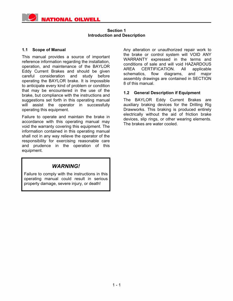
1.1 Scope of Manual This manual provides a source of important reference information regarding the installation, operation, and maintenance of the BAYLOR Eddy Current Brakes and should be given careful consideration and study before operating the BAYLOR brake. It is impossible to anticipate every kind of problem or condition that may be encountered in the use of the brake, but compliance with the instructions and suggestions set forth in this operating manual will assist the operator in successfully operating this equipment. Failure to operate and maintain the brake in accordance with this operating manual may void the warranty covering this equipment. The information contained in this operating manual shall not in any way relieve the operator of the responsibility for exercising reasonable care and prudence in the operation of this equipment.
WARNING! Failure to comply with the instructions in this operating manual could result in serious property damage, severe injury, or death!
Any alteration or unauthorized repair work to the brake or control system will VOID ANY WARRANTY expressed in the terms and conditions of sale and will void HAZARDOUS AREA CERTIFICATION. All applicable schematics, flow diagrams, and major assembly drawings are contained in SECTION 8 of this manual.
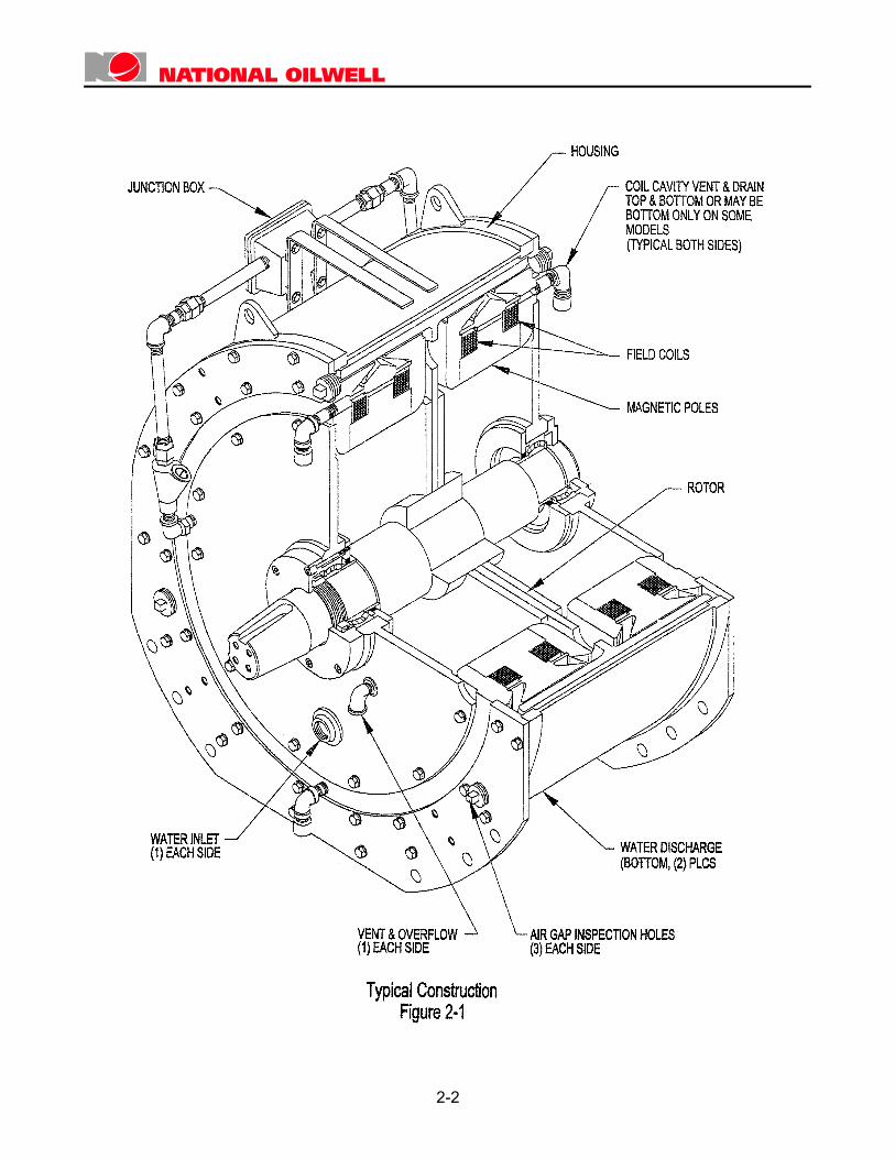
1.2 General Description if Equipment The BAYLOR Eddy Current Brakes are auxiliary braking devices for the Drilling Rig Drawworks. This braking is produced entirely electrically without the aid of friction brake devices, slip rings, or other wearing elements. The brakes are water cooled.
1 - 1

Section 2
Summary of Specifications Model 6032 Eddy Current Brake
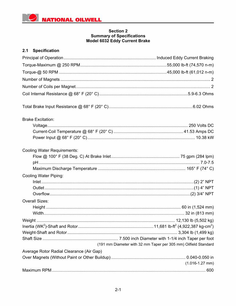
2.1 Specification Principal of Operation .............................................................................. Induced Eddy Current BrakingTorque-Maximum @ 250 RPM.........................................................................55,000 lb-ft (74,570 n-m)Torque-@ 50 RPM ...........................................................................................45,000 lb-ft (61,012 n-m)Number of Magnets ............................................................................................................................... 2Number of Coils per Magnet.................................................................................................................. 2Coil Internal Resistance @ 68° F (20° C) ...........................................................................5.9-6.3 Ohms
Total Brake Input Resistance @ 68° F (20° C).......................................................................6.02 Ohms
Brake Excitation: Voltage....................................................................................................................... 250 Volts DC Current-Coil Temperature @ 68° F (20° C) ........................................................... 41.53 Amps DC Power Input @ 68° F (20° C)........................................................................................... 10.38 kW
Cooling Water Requirements: Flow @ 100° F (38 Deg. C) At Brake Inlet.......................................................... 75 gpm (284 lpm) pH ........................................................................................................................................ 7.0-7.5 Maximum Discharge Temperature .......................................................................... 165° F (74° C)Cooling Water Piping: Inlet .................................................................................................................................(2) 2” NPT Outlet ..............................................................................................................................(1) 4” NPT Overflow.......................................................................................................................(2) 3/4” NPTOverall Sizes: Height .................................................................................................................. 60 in (1,524 mm) Width....................................................................................................................... 32 in (813 mm)Weight ..................................................................................................................... 12,130 lb (5,502 kg)Inertia (WK2)-Shaft and Rotor................................................................11,681 lb-ft2 (4,922,387 kg-cm2)Weight-Shaft and Rotor ............................................................................................. 3,304 lb (1,499 kg)Shaft Size ................................................................ 7.500 inch Diameter with 1-1/4 inch Taper per foot
(191 mm Diameter with 32 mm Taper per 305 mm) Oilfield Standard
Average Rotor Radial Clearance (Air Gap) Over Magnets (Without Paint or Other Buildup) ............................................................... 0.040-0.050 in
(1.016-1.27 mm)
Maximum RPM .................................................................................................................................. 600
2-1
2-2
Section 3
Installation
3.1 General The BAYLOR Brake should be cradle mounted on the drawworks structure. The drawworks manufacturer furnishes the adapter mounting components as well as the disengaging coupling between the brake and the drum shaft of the drawworks. The necessary shifting mechanism and related accessories should be furnished by the customer.
CAUTION! Heat removal from the rotor in the BAYLOR Brake is accomplished by cooling water. The movement of the rotor through the water is necessary to keep the rotor and magnet from overheating. To avoid damage to the brake, use a coupling that allows rotation of the rotor in either direction at all times. DO NOT USE AN OVERRUNNING TYPE CLUTCH.
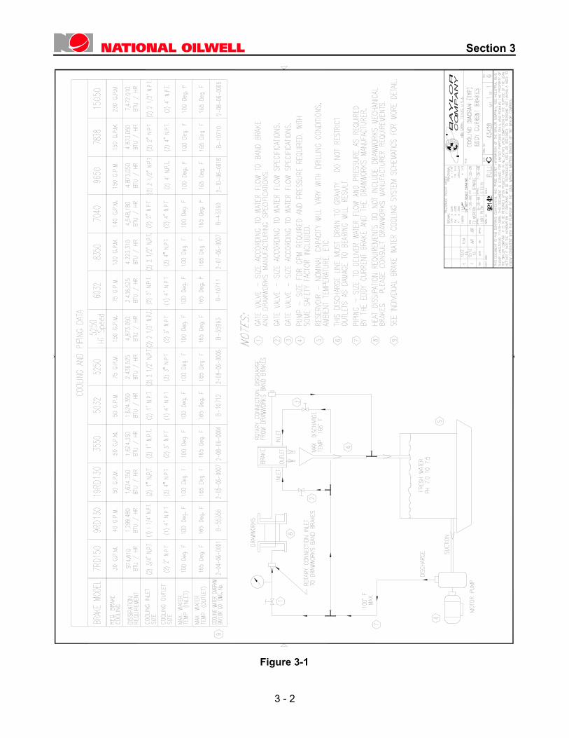
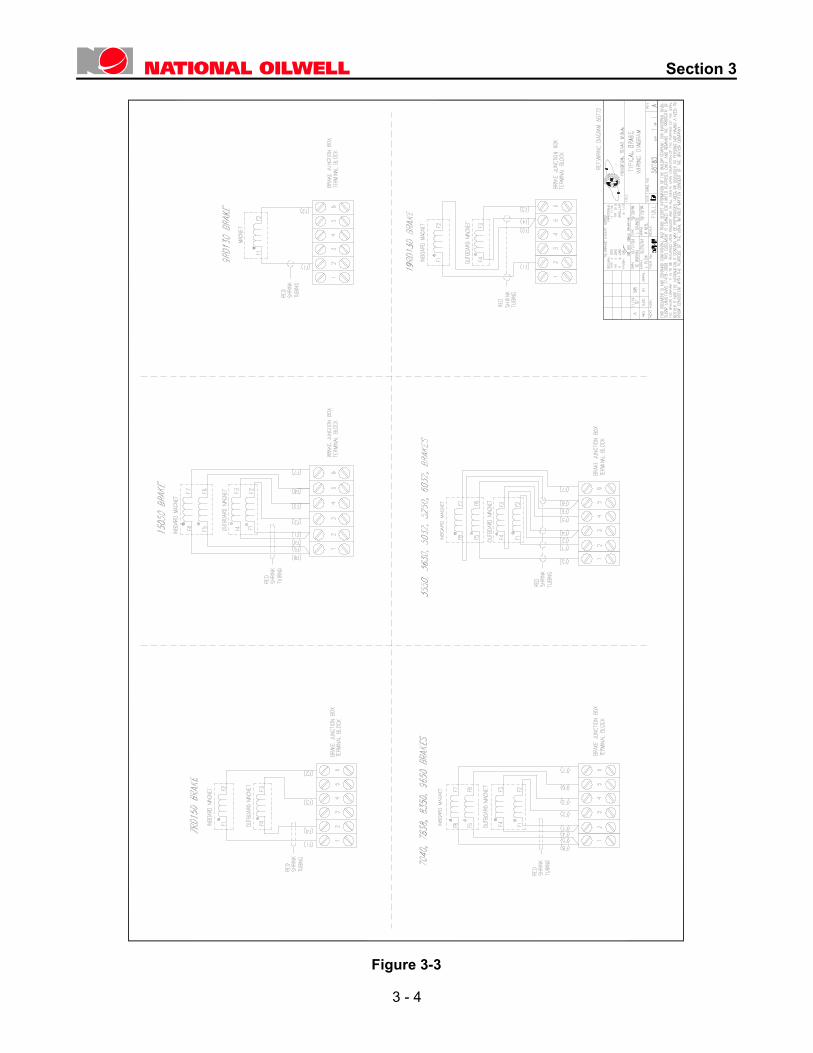
A standard mounting flange on the outboard bearing cap is provided by National Oilwell for mounting water and/or air tube assemblies. The required tube assemblies are furnished by the drawworks manufacturer and should be installed in accordance with their instructions. Electrical control wiring and cooling system water piping should be installed in accordance with the drawings contained in this section. A minimum of five-thread engagement should be maintained on all threaded connections. Figure 3-1 illustrates a standard Brake cooling configuration without a heat exchanger. Figure 3-3 illustrates a standard Brake cooling system with a heat exchanger. A typical closed loop cooling system which provides the greatest and best degree of protection against corrosion / erosion with adequate flow and temperature protection for the BAYLOR Brake. These closed loop systems are manufactured to provide proper cooling for the particular size BAYLOR Brake and can also be capacity sized to cool other portions of the drawworks drive
Figure 3-3 shows the electrical connections for the magnet coils and power input to the junction box.
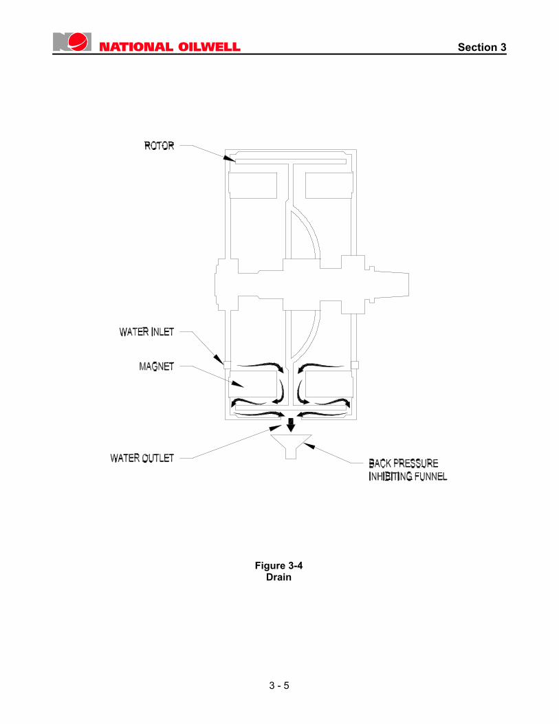
CAUTION! The water outlet(s) at the bottom of the brake should not be hard piped or otherwise restricted. This should be free-flowing, gravity drain. A funnel-type drain as illustrated in Figure 3-4 is preferred. Do not plug, pipe, connect hoses to, otherwise obstruct the water overflow outlets, located on the brake just below the shaft centerline. These overflow outlets provide a warning of improper water flow conditions.
Removal of heat from the Brake is most important. Absence of proper cooling water flow could damage the rotor. Proper cooling water flow at all times will prolong Brake life for many years. As illustrated in Figure 3-4 the BAYLOR Eddy Current Brake allows cooling water to flow over the lower sections of the magnets and rotor before it exits at the bottom. If the cooling water outlets are restricted, the water level inside the Brake will increase to a level which could damage the Bearing grease seals and permit water to enter the bearing cavity with ultimate damage resulting to the bearing.
CAUTION! The BAYLOR Eddy Current Brake is not designed to operate with the cooling water internal of the brake at other than atmospheric pressure. For proper brake operation insure that brake cooling water flows unrestricted through the brake with gravity discharge and unrestricted flow back to the cooling water reservoir.
3 - 1
Section 3
Figure 3-1
3 - 2
Section 3
3 - 3
Figure 3-2
Section 3
3 - 4
Figure 3-3
Section 3
Figure 3-4 Drain
3 - 5
Section 3
B
S
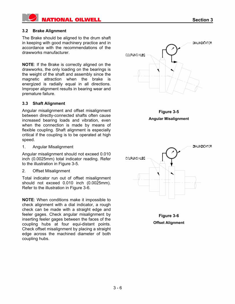
3.2 rake Alignment The Brake should be aligned to the drum shaft in keeping with good machinery practice and in accordance with the recommendations of the drawworks manufacturer. NOTE: If the Brake is correctly aligned on the drawworks, the only loading on the bearings is the weight of the shaft and assembly since the magnetic attraction when the brake is energized is radially equal in all directions. Improper alignment results in bearing wear and premature failure. 3.3 haft Alignment Angular misalignment and offset misalignment between directly-connected shafts often cause increased bearing loads and vibration, even when the connection is made by means of flexible coupling. Shaft alignment is especially critical if the coupling is to be operated at high speed. 1. Angular Misalignment Angular misalignment should not exceed 0.010 inch (0.0025mm) total indicator reading. Refer to the illustration in Figure 3-5. 2. O
g hubs.
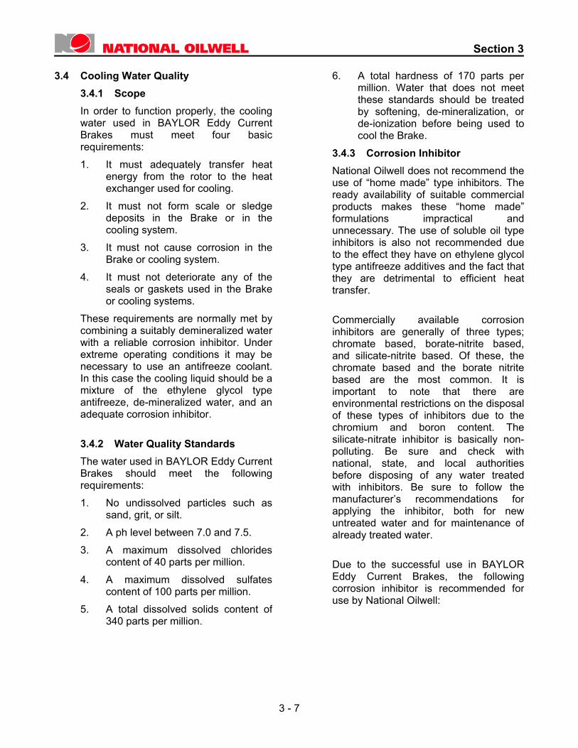
ffset Misalignment Total indicator run out of offset misalignment should not exceed 0.010 inch (0.0025mm). Refer to the illustration in Figure 3-6. NOTE: When conditions make it impossible to check alignment with a dial indicator, a rough check can be made with a straight edge and feeler gages. Check angular misalignment by inserting feeler gages between the faces of the coupling hubs at four equi-distant points. Check offset misalignment by placing a straight edge across the machined diameter of both couplin
Figure 3-5 Angular Misalignment
Figure 3-6 Offset Alignment
3 - 6
Section 3
3.4 Cooling Water Quality 3.4.1 Scope In order to function properly, the cooling
water used in BAYLOR Eddy Current Brakes must meet four basic requirements:
1. It must adequately transfer heat energy from the rotor to the heat exchanger used for cooling.
2. It must not form scale or sledge deposits in the Brake or in the cooling system.
3. It must not cause corrosion in the Brake or cooling system.
4. It must not deteriorate any of the seals or gaskets used in the Brake or cooling systems.
These requirements are normally met by combining a suitably demineralized water with a reliable corrosion inhibitor. Under extreme operating conditions it may be necessary to use an antifreeze coolant. In this case the cooling liquid should be a mixture of the ethylene glycol type antifreeze, de-mineralized water, and an adequate corrosion inhibitor.
3.4.2 Water Quality Standards The water used in BAYLOR Eddy Current
Brakes should meet the following requirements:
1. No undissolved particles such as sand, grit, or silt.
2. A ph level between 7.0 and 7.5. 3. A maximum dissolved chlorides
content of 40 parts per million. 4. A maximum dissolved sulfates
content of 100 parts per million. 5. A total dissolved solids content of
340 parts per million.
6. A total hardness of 170 parts per million. Water that does not meet these standards should be treated by softening, de-mineralization, or de-ionization before being used to cool the Brake.
3.4.3 Corrosion Inhibitor National Oilwell does not recommend the
use of “home made” type inhibitors. The ready availability of suitable commercial products makes these “home made” formulations impractical and unnecessary. The use of soluble oil type inhibitors is also not recommended due to the effect they have on ethylene glycol type antifreeze additives and the fact that they are detrimental to efficient heat transfer.
Commercially available corrosion inhibitors are generally of three types; chromate based, borate-nitrite based, and silicate-nitrite based. Of these, the chromate based and the borate nitritebased are the most common. It is important to note that there are environmental restrictions on the disposal of these types of inhibitors due to the chromium and boron content. The silicate-nitrate inhibitor is basically non-polluting. Be sure and check with national, state, and local authorities before disposing of any water treated with inhibitors. Be sure to follow the manufacturer’s recommendations for applying the inhibitor, both for new untreated water and for maintenance of already treated water.
Due to the successful use in BAYLOR Eddy Current Brakes, the following corrosion inhibitor is recommended for use by National Oilwell:
3 - 7
Section 3
PENCOOL 2000
(Previously Called Nalcool 2000) The Penray Companies 440 Denniston Court Wheeling, Illinois 60090
It is recommended that this inhibitor be purchased through a local distributor so that proper field support in their use is readily available.
3.4.4 Usage of Antifreeze Standards Only ethylene glycol type antifreezes are
to be used in BAYLOR Eddy Current Brakes due to the operating temperature generated.
NOTE: Chromate type rust inhibitors are not to be used with ethylene glycol antifreezes. The resulting mixture forms a sludge. It is recommended that the Brake cooling fluid not exceed 68% ethylene glycol. Levels of ethylene glycol higher than this will lower the freezing point of the Brake cooling fluid, but will not provide adequate heat transfer.
If the antifreeze contains corrosion inhibitors, it is not recommended to add additional inhibitors to the original mixture or for maintenance of a used mixture. This practice can actually cause corrosion of the Brake. If the corrosion inhibitors in this type of solution are no longer effective the entire content of the cooling system should be replaced by a fresh mixture.
National Oilwell does not recommend the use of antifreezes containing anti-leak compounds. These compounds can cause plugging of water passages and reduction in effective heat transfer rates, resulting in a Brake that fails from overheating. Be sure to dispose of used antifreeze mixtures according to the manufacturer’s recommendations and the applicable environmental authorities recommendation.
3.5 Cooling System Capacity Calculation HEAT PRODUCED = BTU/MINUTE = T X RPM X 42.4 5250 Where T = Torque in FT.-LBS This may be used directly to size a radiator or other type of heat exchanger. When the Brake is not producing torque continuously the heat produced must be multiplied by the duty cycle. For example, normal “tripping in” requires that the Brake produce torque only one-third of the time. Therefore the calculated BTU/min would be multiplied by 1/3. For a tank or reservoir type cooling system the storage capacity is calculated by: LBS of water = BTU/min X t Temp Where t = Time in minutes of operation Temp = 165 Degrees F - Temperature of water entering Reservoir. Gallons of water = LBS. of water 8.34 If inlet temperature of cooling water to the Brake is much higher than 100 Degrees F, note that the flow required goes up drastically to cool the Brake, as illustrated in Figure 3-7.
3 - 8
Section 3
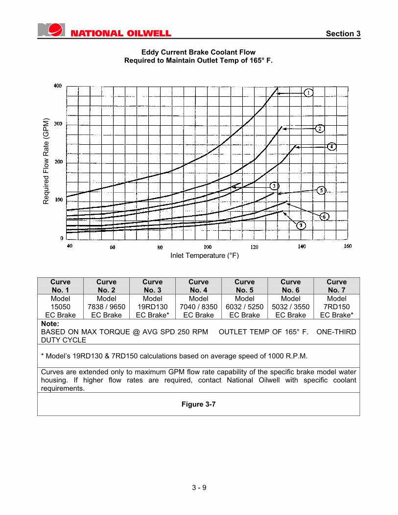
Eddy Current Brake Coolant Flow
Required to Maintain Outlet Temp of 165° F.
Req
uire
d Fl
ow R
ate
(GPM
)
Inlet Temperature (°F)
Curve No. 1
Curve No. 2
Curve No. 3
Curve No. 4
Curve No. 5
Curve No. 6
Curve No. 7
Model 15050
EC Brake
Model 7838 / 9650 EC Brake
Model 19RD130 EC Brake*
Model 7040 / 8350 EC Brake
Model 6032 / 5250 EC Brake
Model 5032 / 3550 EC Brake
Model 7RD150
EC Brake* Note: BASED ON MAX TORQUE @ AVG SPD 250 RPM OUTLET TEMP OF 165° F. ONE-THIRD DUTY CYCLE
* Model’s 19RD130 & 7RD150 calculations based on average speed of 1000 R.P.M.
Curves are extended only to maximum GPM flow rate capability of the specific brake model water housing. If higher flow rates are required, contact National Oilwell with specific coolant requirements.
Figure 3-7
3 - 9
Section 3
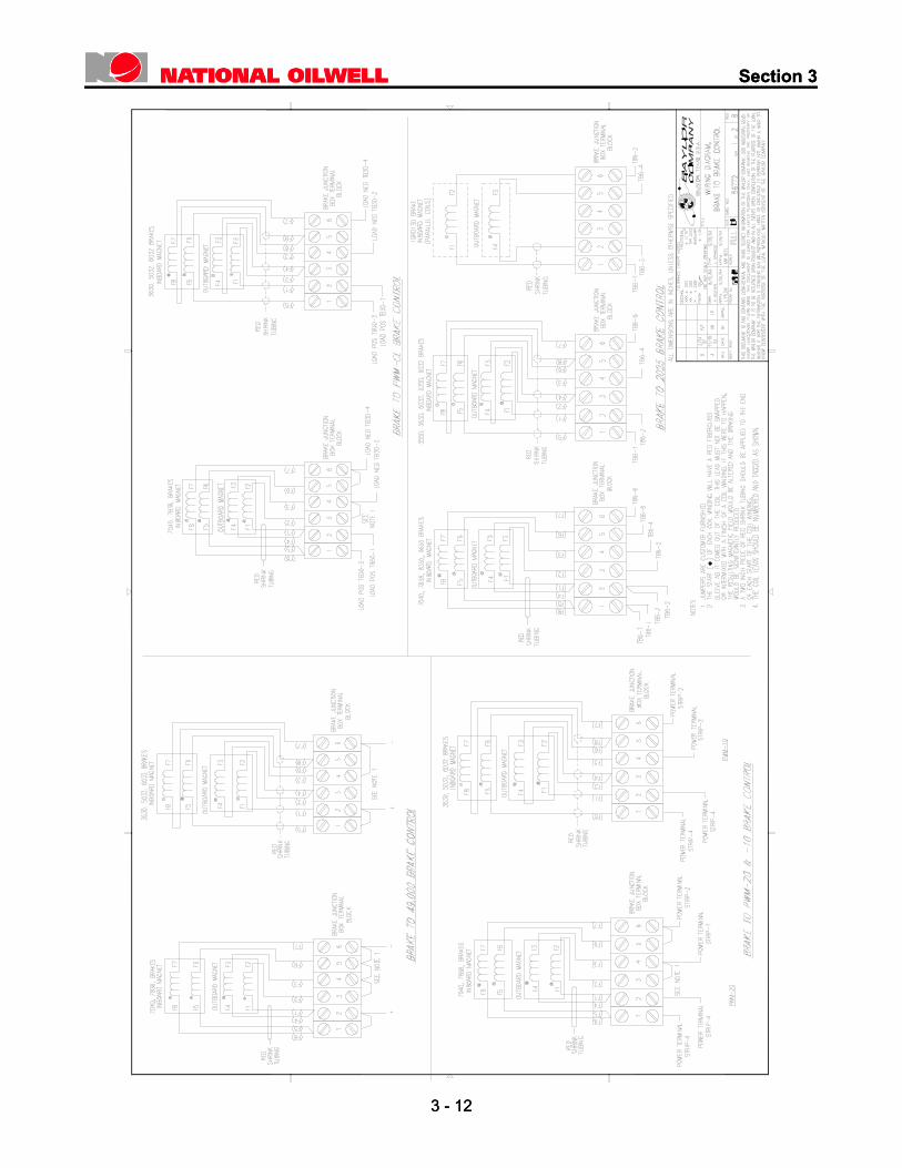
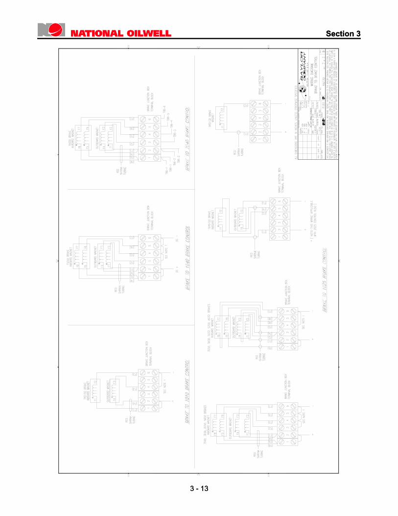
B3.6 rake Field Coil Polarity
Correct field coil polarity is extremely important in obtaining maximum torque from the BAYLOR Eddy Current Brake. There are a number of methods for determining correct field coil polarity. None of these methods are totally accurate, however, if the following instructions are closely followed, good results may be obtained. The best method is utilized by National Oilwell during coil manufacture. During the coil winding process, the starting of the winding and the ending are tagged. At Brake final assembly knowing the start and finish of each coil permits accurate determination of how to tag each coil lead to insure proper Brake polarity. It is very important to maintain the coil lead tags during any period of maintenance or parts replacement in the field to insure proper polarity after all work has been
ccomplished.
erformed to determine correct Brake polarity:
1. IwaohinpCsmCddsrr to progress
a In the field, the following tests may bep
f Brake polarity is not correct, the Brakeill appear weak and not as responsive toctuation of the Driller’s Control. Tobtain a reference point as to the Brake’solding capacity, raise the traveling block to the derrick so that three joints of drillipe are visible. Turn the Brake Driller’sontrol “full on” and allow about 5econds for full saturation of the Brakeagnetic circuit. Then with the Eddyurrent Brake fully energized, releaserawworks friction brake and allow pipe toescend into the bore hole. As theecond joint of drill pipe starts through theotary table, time the interval of time itequires for this second joint
into the bore hole. Next, turn off electrical supply to BAYLOR Brake. Lock out circuit breakers to insure safe conditions while performing work in and around Brake and Control System. Remove cover of Brake Junction Box. Mark present position of coil leads F7 and F8. Reverse the position of these two coil leads, that is, disconnect F7 and F8,then reconnect F7 where F8 was connected and F8 where F7 was connected. Turn electrical power on and re-test by timing length
of time for second joint of drill pipe to pass through rotary table. Compare the results of these two tests. If polarity was correct initially, then drill pipe would have taken longer to enter bore hole during first test. On the basis of these two tests, chose correct junction box coil lead onnection for correct polarity.
2. SBrake coil polarity. Procedure is as f
a. T
c
econd method of determining correct
ollows: urn off electrical supply to Baylor Brake. ock out circuit breakers to insure safe onditions while performing work in and round Brake and Control System.emove Brake junction box cover. Make
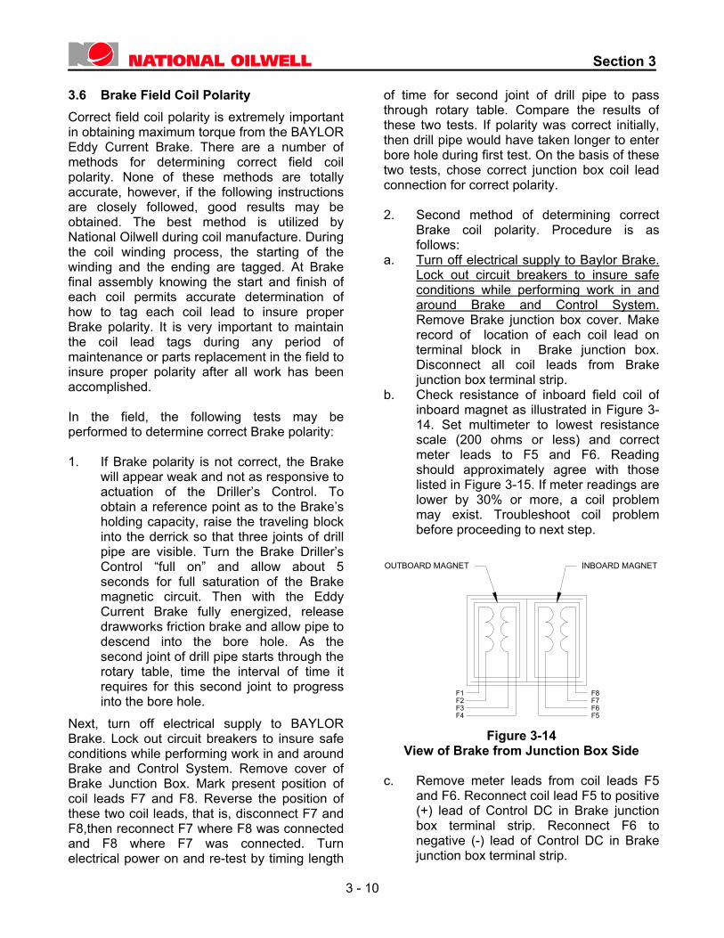
ecord of location of each coil lead on erminal block in Brake junction box. isconnect all coil leads nction box terminal strip. heck resistance of inboard field coil of board magnet as illustrated in Figure 3-4. Set multimeter to lowest resistance cale (200 ohms or less) and correct eter leads to F5 and F6. Reading
hould approximately agree with those sted in Figure 3-15. If meter readings are wer by 30% or more, a coil problem ay exist. Troubleshoot coil problem
Figure 3-14
emove meter leads from coil leads F5 nd F6. Reconnect coil lead F5 to positive +) lead of Control DC in Brake junction ox terminal strip. Reconnect F6 to egative (-) lead of Control DC in
LcaRrtD from Brake ju
b. Cin1smslilombefore proceeding to next step.
View of Brake from Junction Box Side
c. Ra(bn Brake junction box terminal strip.
F1F2F3
F7F6
F8
OUTBOARD MAGNET INBOARD MAGNET
F4 F5
3 - 10
Section 3
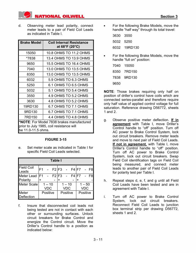
d. Observing meter lead polarity, connect
meter leads to a pair of Field Coil Leadsas indicated in Table I.
Brake Model Coil Internal Resistance
at 68°F (20°C)
15050 10.8 OHMS TO 11.2 OHMS *7838 13.4 OHMS TO 13.9 OHMS 9650 15.5 OHMS TO 16.4 OHMS 7040 13.0 OHMS TO 13.5 OHMS 8350 13.0 OHMS TO 13.5 OHMS 6032 5.9 OHMS TO 6.3 OHMS 5250 6.1 OHMS TO 6.5 OHMS 5032 5.1 OHMS TO 5.4 OHMS 3550 4.9 OHMS TO 5.2 OHMS 3630 4.8 OHMS TO 5.2 OHMS
19RD130 6.7 OHMS TO 7.1 OHMS 9RD130 6.7 OHMS TO 7.1 OHMS 7RD150 4.4 OHMS TO 4.8 OHMS
*NOTE: For Model 7838 brakes manufactured prior to July 1985, coil resistance will be 11.0-11.5 ohms.
FIGURE 3-15 e. Set meter scale as indicated in Table I for
specific Field Coil Leads selected.
Table I
Field Coil Leads F1 - F2 F3 - F4 F7 - F8
Meter Lead Polarity
F1 - F2 + -
F3 - F4 + -
F7 - F8+ -
Meter Scale 1 – 10 VDC
1 – 10 VDC
1 – 50 VDC
Meter Deflection
Positive Positive Positive
f. Insure that disconnected coil leads not
being tested are not in contact with eachother or surrounding surfaces. Unlockcircuit breakers for Brake Control andenergize the Control circuit. Move theDriller’s Control handle to a position asindicated below:
• For the following Brake Models, move the handle “half way” through its total travel: 3630 3550 5032 5250 6032 19RD130
• For the following Brake Models, move the
handle “full on” position: 7040 15050 8350 7RD150 7838 9RD130 9650
NOTE: Those brakes requiring only half on position of driller’s control have coils which are connected series-parallel and therefore require only half value of applied control voltage for fullsaturation. Reference drawing D56772, sheets 1 and 2. g. Observe positive meter deflection. If in
agreement with Table I, move Driller’s Control handle to “off” position. Turn off AC power to Brake Control System, lock out circuit breakers. Remove meter leads and move to next pair of Field Coil Leads. If not in agreement, with Table I, move Driller’s Control handle to “off” position. Turn off AC power to Brake Control System, lock out circuit breakers. Swap Field Coil identification tags on Field Coil being measured, and connect meter leads to another pair of Field Coil Leads for polarity test per Table I.
h. Repeat steps d, e, f, and g until all Field
Coil Leads have been tested and are in agreement with Table I.
i. Turn off AC power to Brake Control
System, lock out circuit breakers. Reconnect Field Coil Leads to junction box terminal strip per drawing D56772, sheets 1 and 2.
3 - 11
Section 3
Section 3
3 - 12
3 - 12
Section 3
Section 3
3 - 13
3 - 13
Section 3
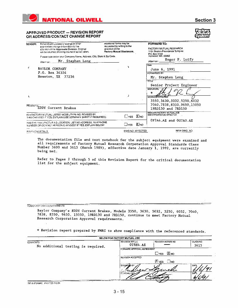
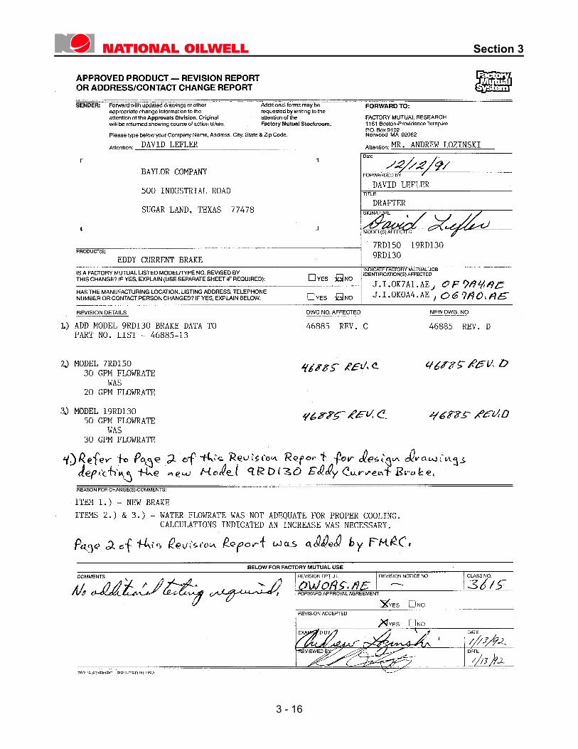
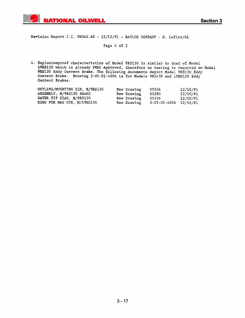
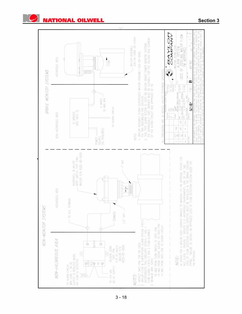
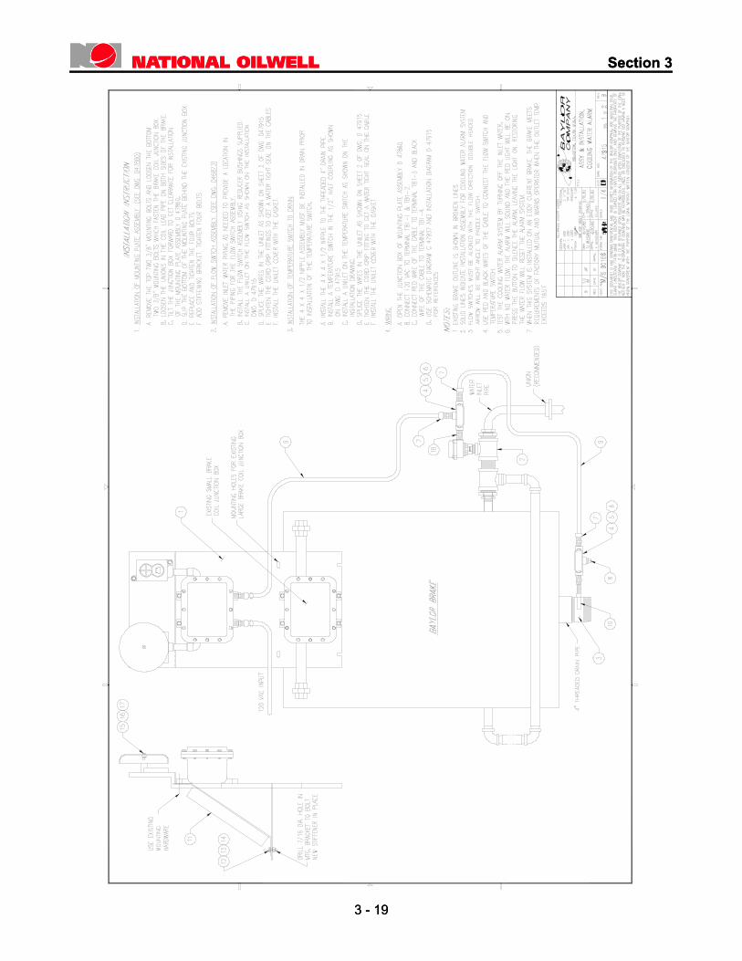
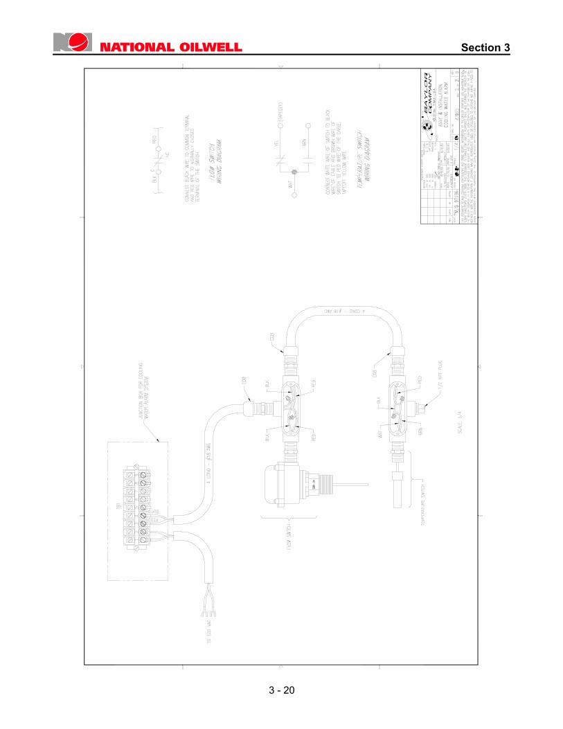
3.7 Certification for Hazardous Location The Factory Mutual Certification of BAYLOR Eddy Current Brakes is reproduced on the following pages. Note that if a Factory Mutual Approved Installation is required, a water flow alarm system must be installed to monitor water cooling flow in the Brake inlet line in accordance with drawing B46765 and drawing D47915 sheets 1 and 2. Copies of these Drawings are included at the end of this section.
3 - 14
Section 3
3 - 15
Section 3
3 - 16
Section 3
Section 3
3 - 17
3 - 17
Section 3
3 - 18
12
Section 3
Section 3
3 - 19
3 - 19
Section 3
3 - 20
Section 4
Theory of Operation
4.1 General When the steel rotor rotates through the stationary magnetic field, currents are induced in the rotor. These currents, commonly called “eddy currents”, produce a magnetic field which interacts with the stationary field. This field interaction produces a force, which opposes rotor rotation, and provides the braking torque for the BAYLOR Brake. The Eddy Current Brake provides high braking torque at low rotor speeds. This is a distinct advantage over other types of braking systems such as the water brake. The braking torque of the Eddy Current Brake is dependent on the strength of the stationary magnetic field, rotor speed, and rotor temperature. Torque increases with magnetic field strength and with rotor speed. Torque decreases as rotor temperature rises and the rotor expands which widens the air gap. The strength of the stationary magnetic field is controlled by the field coil in proportion to the braking requirements. The eddy currents induced in the rotor produce heat. This rotor heat must be kept within acceptable limits or braking torque will be reduced. To maintain rotor temperature within acceptable limits, a cooling system is required. A steady flow of water is directed into the area containing the rotor, as illustrated in Figure 3-4. The movement of the rotor through this water as it turns provides uniform cooling of the rotor surface. If the flow of cooling water fails while the brake is in operation the rotor will become overheated. In this state the rotor will be damaged if a safe cooling procedure is not followed. Consult Section 6 of this manual for the proper procedure to use.
4.2 Brake Operation on Rig When a BAYLOR Eddy Current Brake is installed on a rig its response may vary depending upon the following items:
• Brake torque capacities may vary + or –5% between individual units.
• When the brake becomes overheated it will lose some of its torque capacity.
• Normal reaction time for the brake to reach maximum braking torque is approximately 2 seconds. This may vary depending upon the Brake Control System employed.
• Normal reaction time for the brake to decay to zero braking torque is approximately 1-2 seconds. This may vary depending upon the Brake Control System employed.
• As the brake ages, the air gap between the rotor and the magnets may increase due to rust or erosion which will cause a decrease in brake output torque.
With all these factors in mind, the operator must learn and get a feel for the brake response time during the early stages of tripping when the loads are lighter. When the load exceeds the brake capacity note that the brake will not be able to control or properly decelerate the load. Proper operation of the brake is to apply the Eddy Current Brake before releasing the main drawworks friction brake when tripping into the bore hole.
CAUTION! When the brake is being used close to its Maximum torque capacity apply the Eddy Current Brake before releasing the main drawworks friction brake when tripping into the bore hole.
4 - 1
Section 4
4.2.1 Drill Assist Operation If the brake is used for “drill assist” where
the rotor speed is very limited, it is recommended that no more than half of full rated DC voltage be applied to the field coils continuously. The brake’s primary purpose as an auxiliary brake isto dissipate the energy of drill pipe or casing being lowered into the bore hole. For this specific purpose, the field coils are designed to accommodate a duty cycle of full DC voltage “on time” of 20 seconds out of every 60 seconds. To increase the duty cycle to 100%, or an “on time” of 60 seconds out of 60 seconds will create excessive heat buildup within the individual conductors of the field coils. As the electrical insulation system of the field coil has excellent dielectric characteristics, it also is an excellent thermal insulator. The heat produced internal of the field coil due to the DC current passing through each conductor will continue to rise until, within a short period of time, the insulation system will de-grade and turn-to-turn shorting will occur with ultimate failure of the field coil. It is also interesting to note that the torque curves for BAYLOR Eddy Current Brakes all have a similar characteristic. The torque produced at very low drum shaft speeds (0-20 r.p.m.) is approximately the same for various excitation values. In other words, the brake torque produced at 15 r.p.m. is about the same, at full applied excitation, as the torque with 33% applied excitation. Therefore, the brake, utilized for “drill assist”, will perform at the low speed drum requirements of feed off at 1/3 of excitation as well as performance at full excitation. This can reduce the excitation to the larger capacity brakes from 21 kW to 7 kW with the obvious fuel savings and reduction of thermal load of field coils.
Operation of the brake at very low speeds during drill assist, with full excitation, will also contribute to excessive wear to the I.D. of the rotor and the O.D. of the magnets. At very low rotor speeds, with full excitation to the field coils, the magnetic attraction between magnets and rotor is greater than the collapse strength of the rotor material. Pull over will occur where the outer circumference of the rotor drum will pull down and contact the O.D. of the magnet. The resultant contact, at slow speed, will gaul and gouge the surfaces of rotor and magnets. This mechanical contact will increase the air gap between the rotor I.D. and the magnet O.D. such that maximum torque of the brake will be reduced.
In conclusion, to utilize the BAYLOR Eddy Current Brake in the drill assist mode requires specific attention to how much excitation is applied to the field coils. Continuous operation at full excitation can significantly shorten the life of the field coils and increase the air gap dimension such that reduced torque output will result.
NOTE National Oilwell manufactures several different types of Control Systems for use with the BAYLOR Eddy Current Brakes. Each Control System design incorporates a different method of supplying reduced voltage to the brake during drill assist operations. Consult your Brake Control System Manual to determine the proper operational technique for drill assist conditions.
4 - 2
Section 5
Accessories and Options
5.1 General In striving to satisfy the needs of all customers, National Oilwell offers the following accessories and options.
5.1.1 Brake Controller Each Eddy Current Brake requires a
brake controller which supplies voltage to the field coils. The brake controller is a variable DC voltage power supply which controls the amount of excitation delivered to the brake field coils as a function of the position of a driller’s control lever. A complete controller system consists of an isolated power transformer, a power control unit, and a driller’s control.
5.1.2 Special Brake Shafts Certain applications may require an
optional special shaft on the brake. Double-ended shafts and special coupling features have been manufactured in the past. If the brake is required to operate in highly regulated areas such as the North Sea, then special shafts may be required to conform to low temperature requirements. One of these may fit your needs; if not, a new “special” can be designed to your specifications.
5.1.3 Brake Cooling Packages Each Eddy Current Brake needs a
cooling system to remove the heat from the brake while the brake is being used. National Oilwell builds brake water cooling systems to meet a variety of operational and regulatory requirements. In addition to cooling water for the BAYLOR Eddy Current Brake, extra capacity can be designed into the system for the main drawworks friction brake, top drives, electric drive motors, and other rig cooling requirements.
5.1.4 Cooling Water Alarm A cooling water alarm system is available
to monitor flow and temperature of the coolant to the brake. This system warns the operator whenever cooling to the brake has been impaired. It can prevent the need for expensive repairs.
5.1.5 Safety Monitoring Device A safety monitor system manufactured by
National Oilwell which signals the potentially dangerous loss of control of brake excitation is available for BAYLOR Brakes.
If there is a need for further information about any of the aforementioned items, or if you have other special requirements, please contact National Oilwell Sales Department or Service Department. Telephone Number in the U.S.A. ....................................................(281) 240-6111 Fax Number: ...................................................................................(281) 274-0426
These Numbers are in operation 24 hours/day, 7 days/week
5 - 1
Section 5
5.1.6 Parts and Service Parts and service are available from the factory:
National Oilwell 500 Industrial Blvd. Sugar Land, Texas 77478-2898 Phone: (281) 240-6111 Fax: (281) 274-0426 Or from the following Service Centers:
National Oilwell - HITEC 266 Auchmill Road Bucksburn, Aberdeen Scotland AB21 9NB Phone: 44 1224 714499 Fax: 44 1224 714599
ABB SERVICES AS Torneroseveien 4, P.O. Box 173 N-4033 FORUS Norway Phone: 47 51 678022 Fax: 47 51 678683
GE KEPPLE ENERGY SERVICES PTE LTD No.2, Pioneer Sector 3, Jurong, Singapore 2262 Phone: 65 551 9500 Fax: 65 861 2054
INTERSEL ENGINEERING SERVICES P.O. Box 4726 Sharjah, United Arab Emirates Phone: 971 6 52 85 118 Fax: 971 6 52 81 189
RIMES ELECTRO MECANICA, C.A. Av. Intercomunal Ciudad Ojeda 4019 Zulia, Venezuela Phone: 58 65 411 763 Fax: 58 65 413 261
5 - 2
Section 6
Maintenance and Service
6.1 General An Inspection and Maintenacnce Schedule is provided at the end of this section. 6.1.1 Lubrication To maintain the lubricant volume, add
approximately 2 ounces of grease to each bearing cavity each 24-hour period, or before each trip into the hole with pipe. There is a grease fitting for each of the two bearings, and each must be independently lubricated (See Figure 6-1). The recommended grease is a NLGI No.2, water resistant (Lithium base) grease. A good grade of lithium or sodium base ball and roller bearing grease may be used. The bearings and seals will not be harmed by excess grease. It will simply enter the cooling water stream by momentarily lifting the seal lip to relieve pressure. Drawworks manufacturers and users may connect the grease inlet holes in the bearing caps to lubrication header blocks with tubing to facilitate lubrication from a remote point. This is satisfactory if the tubing is regularly inspected, and it is determined that the required amount of grease is actually reaching the bearing.
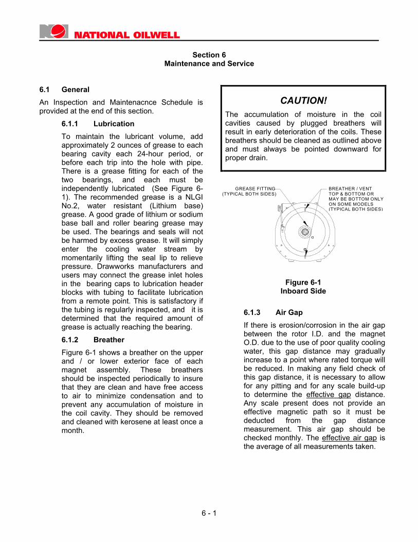
6.1.2 Breather Figure 6-1 shows a breather on the upper
and / or lower exterior face of each magnet assembly. These breathers should be inspected periodically to insure that they are clean and have free access to air to minimize condensation and to prevent any accumulation of moisture in the coil cavity. They should be removed and cleaned with kerosene at least once a month.
CAUTION! The accumulation of moisture in the coil cavities caused by plugged breathers will result in early deterioration of the coils. These breathers should be cleaned as outlined above and must always be pointed downward for proper drain.
Figure 6-1
Inboard Side 6.1.3 Air Gap If there is erosion/corrosion in the air gap
between the rotor I.D. and the magnet O.D. due to the use of poor quality cooling water, this gap distance may gradually increase to a point where rated torque will be reduced. In making any field check of this gap distance, it is necessary to allow for any pitting and for any scale build-up to determine the effective gap distance. Any scale present does not provide an effective magnetic path so it must be deducted from the gap distance measurement. This air gap should be checked monthly. The effective air gap is the average of all measurements taken.
GREASE FITTING(TYPICAL BOTH SIDES)
BREATHER / VENTTOP & BOTTOM OR MAY BE BOTTOM ONLY ON SOME MODELS (TYPICAL BOTH SIDES)
6 - 1
Section 6
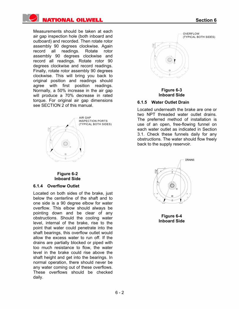
Measurements should be taken at each
air gap inspection hole (both inboard and outboard) and recorded. Then rotate rotor assembly 90 degrees clockwise. Again record all readings. Rotate rotorassembly 90 degrees clockwise and record all readings. Rotate rotor 90 degrees clockwise and record readings. Finally, rotate rotor assembly 90 degrees clockwise. This will bring you back to original position and readings should agree with first position readings. Normally, a 50% increase in the air gap will produce a 70% decrease in rated torque. For original air gap dimensions see SECTION 2 of this manual.
O
Figure 6-2
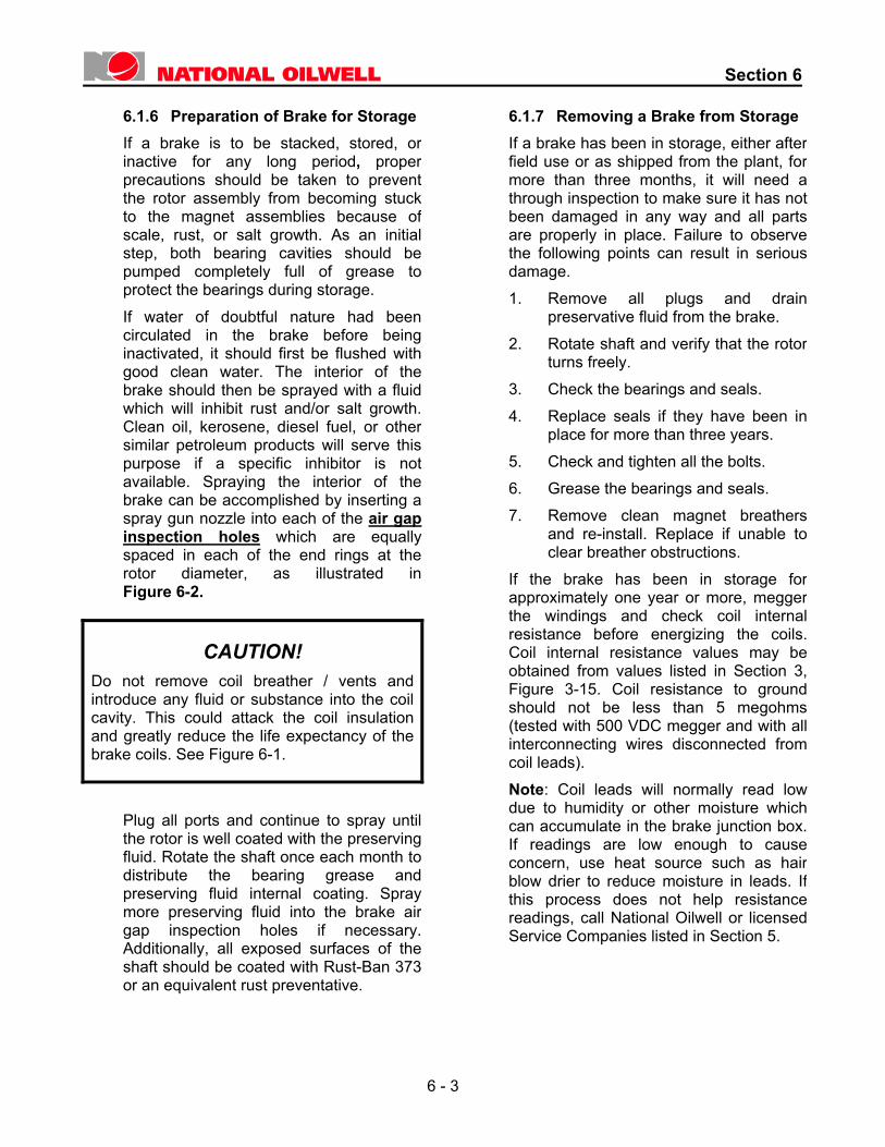
Inboard Side 6.1.4 verflow Outlet Located on both sides of the brake, just
below the centerline of the shaft and to one side is a 90 degree elbow for water overflow. This elbow should always be pointing down and be clear of any obstructions. Should the cooling water level, internal of the brake, rise to the point that water could penetrate into the shaft bearings, this overflow outlet would allow the excess water to run off. If the drains are partially blocked or piped with too much resistance to flow, the water level in the brake could rise above the shaft height and get into the bearings. In normal operation, there should never be any water coming out of these overflows. These overflows should be checked daily.
W
Figure 6-3
Inboard Side 6.1.5 ater Outlet Drain Located underneath the brake are one or
two NPT threaded water outlet drains. The preferred method of installation is use of an open, free-flowing funnel on each water outlet as indicated in Section 3.1. Check these funnels daily for any obstructions. The water should flow freely back to the supply reservoir.
Figure 6-4 Inboard Side
OVERFLOW(TYPICAL BOTH SIDES)
AIR GAPINSPECTION PORTS(TYPICAL BOTH SIDES)
DRAINS
6 - 2
Section 6
6.1.6 Preparation of Brake for Storage If a brake is to be stacked, stored, or
inactive for any long period, proper precautions should be taken to preventthe rotor assembly from becoming stuckto the magnet assemblies because of scale, rust, or salt growth. As an initialstep, both bearing cavities should bepumped completely full of grease toprotect the bearings during storage. If water of doubtful nature had beencirculated in the brake before beinginactivated, it should first be flushed withgood clean water. The interior of thebrake should then be sprayed with a fluidwhich will inhibit rust and/or salt growth.Clean oil, kerosene, diesel fuel, or othersimilar petroleum products will serve thispurpose if a specific inhibitor is notavailable. Spraying the interior of thebrake can be accomplished by inserting aspray gun nozzle into each of the air gap inspection holes which are equallyspaced in each of the end rings at therotor diameter, as illustrated inFigure 6-2.
CAUTION! Do not remove coil breather / vents and introduce any fluid or substance into the coil cavity. This could attack the coil insulation and greatly reduce the life expectancy of the brake coils. See Figure 6-1.
Plug all ports and continue to spray untilthe rotor is well coated with the preservingfluid. Rotate the shaft once each month todistribute the bearing grease andpreserving fluid internal coating. Spraymore preserving fluid into the brake airgap inspection holes if necessary. Additionally, all exposed surfaces of theshaft should be coated with Rust-Ban 373 or an equivalent rust preventative.
6.1.7 Removing a Brake from Storage If a brake has been in storage, either after
field use or as shipped from the plant, for more than three months, it will need a through inspection to make sure it has not been damaged in any way and all parts are properly in place. Failure to observe the following points can result in serious damage.
1. Remove all plugs and drain preservative fluid from the brake.
2. Rotate shaft and verify that the rotor turns freely.
3. Check the bearings and seals. 4. Replace seals if they have been in
place for more than three years. 5. Check and tighten all the bolts. 6. Grease the bearings and seals. 7. Remove clean magnet breathers
and re-install. Replace if unable to clear breather obstructions.
If the brake has been in storage for approximately one year or more, megger the windings and check coil internal resistance before energizing the coils. Coil internal resistance values may be obtained from values listed in Section 3, Figure 3-15. Coil resistance to ground should not be less than 5 megohms (tested with 500 VDC megger and with all interconnecting wires disconnected from coil leads). Note: Coil leads will normally read low due to humidity or other moisture which can accumulate in the brake junction box. If readings are low enough to cause concern, use heat source such as hair blow drier to reduce moisture in leads. If this process does not help resistance readings, call National Oilwell or licensed Service Companies listed in Section 5.
6 - 3
Section 6
6.2 Maintenance and Repairs 6.2.1 Water System Problems If the cooling water supply fails while the
BAYLOR Brake is being used, the heatgenerated in the rotor may build veryquickly. The rotor will expand if the heat isnot properly carried away. As a result, the braking action will be below normal due tothis expansion and the consequentwidening of the air gap between the rotorand magnet assemblies. If the rotoroverheating continues beyond a shortperiod of time, the rotor may suffer severedistortion and require replacement. Thepresence of any cooling water at all andthe temperature of the water will affect thelength of time before which irreversibledamage occurs. It can be simply said thata sufficient flow of cool water will yield along operating life for the Eddy CurrentBrake. If overheating of the rotor occurs, do notimmediately turn on or increase water flowto the brake. First, let the rotor air-cool to 200 to 250 degrees F. The driller shouldthen run the drawworks so that it turns thebrake rotor at a uniform slow speed as thecooling water supply is slowlyreintroduced into the brake. In this waythe rotor will be cooled evenly, and anyout-of-round condition or eccentricity ofthe rotor may possibly be avoided.However, once a rotor becomes severelyoverheated, permanent warping of therotor cylinder is a distinct probability, evenif the above steps are taken to cool it. Onmany rigs, the cooling water systems ofthe BAYLOR Brake and the drawworksmechanical friction brake are paralleledfrom a common source of adequatecapacity for the two systems. Any failureof the cooling water supply then becomesnoticeable promptly.
NOTE! Do not connect the two brake cooling systems in series; that is, where the outlet from the friction brake system is fed to the inlet of the BAYLOR Brake System.
6.2.2 Replacement (Figure 6-5) Initially, before attempting to remove the
old bearing, remove any external components which have been added to the basic brake on the side from which the bearing is to be removed. This would include such items as the hub of the disengaging coupling, any components of a drill feed control drive, any water/air tube components, guards, brackets, etc., which may have been added by the drawworks manufacturer or user and which would interfere with the removal of the bearing involved. In addition, it is necessary to move the brake out of position on the drawworks if an inboard bearing is to be removed, but it is often possible to change an outboard bearing with the brake in place. Refer to the assembly drawing showing the cross section of the brake included in Section 8 of this manual for a better understanding.
To remove a bearing, proceed as follows: 1. Remove the bearing cap: Loosen
and remove the cap screws which fasten the bearing cap to the inner seal retainer.
2. Remove the retaining ring or locknut and lockwasher. (Note: To remove the inboard bearing on a model 7838 brake, reverse the order of steps 1 & 2 above.)
3. Remove the center plate: Loosen and remove the cap screws which fasten the center plate to the inner flange of the magnet assembly. Insert four pusher bolts into the threaded holes located at four equidistant positions about the outer edge of the center plate. Screw in these (4) pusher bolts, evenly, to remove the center plate.
6 - 4
Section 6
NOTE! Care should be taken to exert even pressure on the four pusher bolts. This will move the plate out evenly and avoid damage. The model 6032 brake center plate is cast iron. Be especially careful not to exert uneven pressure on the pusher bolts or the center plate may crack due to its brittle, cast iron, construction. The bearing is now clear and may be removed by conventional procedures.
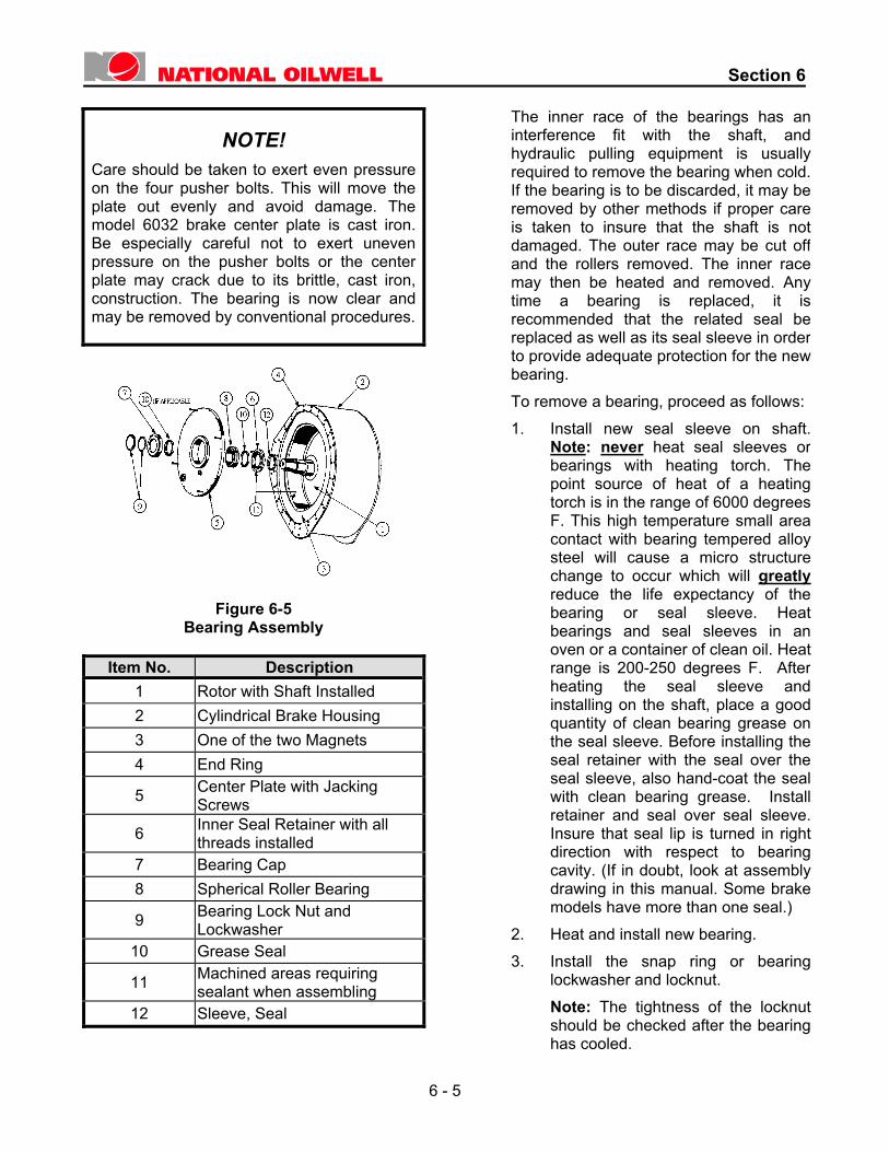
Figure 6-5
Bearing Assembly
Item No. Description 1 Rotor with Shaft Installed 2 Cylindrical Brake Housing 3 One of the two Magnets 4 End Ring
5 Center Plate with Jacking Screws
6 Inner Seal Retainer with all threads installed
7 Bearing Cap 8 Spherical Roller Bearing
9 Bearing Lock Nut and Lockwasher
10 Grease Seal
11 Machined areas requiring sealant when assembling
12 Sleeve, Seal
The inner race of the bearings has an interference fit with the shaft, and hydraulic pulling equipment is usually required to remove the bearing when cold. If the bearing is to be discarded, it may be removed by other methods if proper care is taken to insure that the shaft is not damaged. The outer race may be cut off and the rollers removed. The inner race may then be heated and removed. Any time a bearing is replaced, it is recommended that the related seal be replaced as well as its seal sleeve in order to provide adequate protection for the new bearing.
To remove a bearing, proceed as follows: 1. Install new seal sleeve on shaft.
Note: never heat seal sleeves or bearings with heating torch. The point source of heat of a heating torch is in the range of 6000 degrees F. This high temperature small area contact with bearing tempered alloy steel will cause a micro structure change to occur which will greatlyreduce the life expectancy of the bearing or seal sleeve. Heat bearings and seal sleeves in an oven or a container of clean oil. Heat range is 200-250 degrees F. After heating the seal sleeve and installing on the shaft, place a good quantity of clean bearing grease on the seal sleeve. Before installing the seal retainer with the seal over the seal sleeve, also hand-coat the seal with clean bearing grease. Install retainer and seal over seal sleeve. Insure that seal lip is turned in right direction with respect to bearing cavity. (If in doubt, look at assembly drawing in this manual. Some brake models have more than one seal.)
2. Heat and install new bearing. 3. Install the snap ring or bearing
lockwasher and locknut. Note: The tightness of the locknut should be checked after the bearing has cooled.
6 - 5
Section 6
4. Prior to replacing the center plate,
hand pack the bearing and seal withclean bearing grease. Screw guidepins into two of the tapped holes inthe inner seal retainer to align thecorresponding through holes in thecenter plate and bearing cap.
5. Thoroughly clean the machinedmating surfaces between the innerseal retainer and the center plate,and the inner flange of the magnet assembly. Apply a coating of PartNo. 1885-11-0015, non-hardening,silicone sealant to these surfaces. No gasket is used here since thecavity is not pressured and a sealerserves quite satisfactorily.
6. Install the center plate and pull itfirmly into position by tightening thecap screws which hold it to the innerflange of the magnet assembly.Care should be taken to insure thatthe center plate is drawn up straightand evenly. The rotor shaft shouldbe supported while the center plateis replaced. A “cheater pipe” may beused with a hoist to support it.
7. Install the bearing cap and positionthe cap screws which hold thebearing cap in place. Tighten thesecap screws firmly. Remove the (2)guide pins and replace with theremaining (2) cap screws andtighten firmly.
NOTE! Care should be taken to insure that the pilot diameters of the inner seal retainer and the bearing cap have entered the bore of the center plate straight and both of these parts are straight and firmly affixed to the center plate.
Prior to replacing external parts, remove air gap inspection plugs (Figure 6-2) and check air gap at all three inspection holes. Rotate rotor 90 degrees and take three more readings (this is to check concentricity of rotor). Compare air gap readings. If center plate O.D. and/or magnet pilot diameter is worn, gap at vertical top of brake will be less than (2) gap readings at lower quadrant of brake. If difference is greater than 0.010" (0.25 mm), then it will be necessary to shim between O.D. of center plate and I.D. of magnet assembly. This can be accomplished by loosening the cap screws which retain the center plate to the magnet by two full turns. Using the “cheater pipe” mentioned in 6.2.2.6 lift weight of shaft and rotor assembly such that shim may be inserted between center plate O.D. and magnet pilot diameter (at bottom vertical center line). Tighten cap screws which retain center plate to magnet assembly. Remove “cheater pipe”. Recheck air gaps as outlined previously. Shimming should correct concentricity between magnet O.D. and rotor I.D. and insure equal magnet attraction and reduce rotor pull over.
8. Add sufficient grease to the bearing cavity with a grease gun to insure that the cavity is at least two-thirds filled. The external parts which may have been removed can be replaced after it is determined that the shaft and rotor assembly rotates freely. If it was necessary to move the brake from its position on the drawworks, it should be reinstalled and aligned with the same care as when initially installed.
6 - 6
Section 6
6.3 Electrical Problems and
Troubleshooting All electrical problems must be in one or more of these components. 1. Interconnect cables and wiring. 2. Brake (coils, lead wires, or terminations). 3. Control System (Refer to Control System
Manual). Experience has shown that about 90% of all problems can be traced to interconnect cables and wiring, therefore it is suggested that these be checked first. With power removed, use a 500 VDC megger to check for grounds. Wiring and interconnect cables should be a minimum 1 megohm to ground. Individual magnet coils should be a minimum of 5 megohms to ground. An ohmmeter should be used to check the coils for open or short circuits. Coil resistance is listed in the specifications summary in Section 2.
There is no difference in the inboard and outboard magnets. The leads are numbered for convenience in wiring and to assist in proper coil lead connection to insure proper coil polarity. Outboard magnet leads are F1, F2, F3, and F4. Inboard magnet leads are F5, F6, F7, and F8. If there is a need to convert an inboard magnet to outboard or vice-a-versa the following table should be used: Leads F1 = F8, F3 = F6 F2 = F7, F4 = F5 Therefore, the inboard and outboard magnets are mechanically and electrically interchangeable. Refer to Figure 3-3 Most problems can be solved with the preceding information. Additional checks which may be useful are included in the voltage and resistance checklist in the BAYLOR Brake Control System Manual.
6 - 7
Section 6
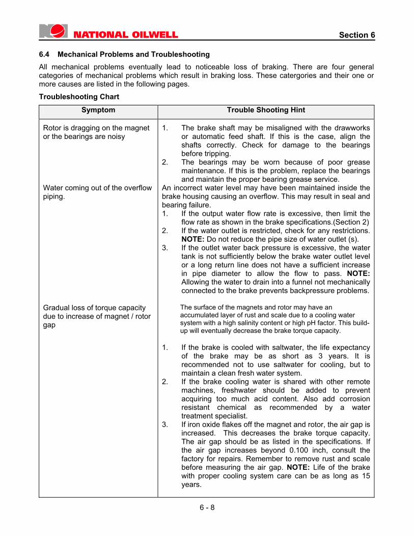
6.4 Mechanical Problems and Troubleshooting All mechanical problems eventually lead to noticeable loss of braking. There are four general categories of mechanical problems which result in braking loss. These catergories and their one or more causes are listed in the following pages.
Troubleshooting Chart Symptom Trouble Shooting Hint
Rotor is dragging on the magnet or the bearings are noisy Water coming out of the overflow piping. Gradual loss of torque capacity due to increase of magnet / rotor gap
1. The brake shaft may be misaligned with the drawworks or automatic feed shaft. If this is the case, align the shafts correctly. Check for damage to the bearings before tripping.
2. The bearings may be worn because of poor grease maintenance. If this is the problem, replace the bearings and maintain the proper bearing grease service.
An incorrect water level may have been maintained inside the brake housing causing an overflow. This may result in seal and bearing failure. 1. If the output water flow rate is excessive, then limit the
flow rate as shown in the brake specifications.(Section 2) 2. If the water outlet is restricted, check for any restrictions.
NOTE: Do not reduce the pipe size of water outlet (s). 3. If the outlet water back pressure is excessive, the water
tank is not sufficiently below the brake water outlet level or a long return line does not have a sufficient increase in pipe diameter to allow the flow to pass. NOTE: Allowing the water to drain into a funnel not mechanically connected to the brake prevents backpressure problems.
The surface of the magnets and rotor may have an accumulated layer of rust and scale due to a cooling water system with a high salinity content or high pH factor. This build-up will eventually decrease the brake torque capacity.
1. If the brake is cooled with saltwater, the life expectancy
of the brake may be as short as 3 years. It is recommended not to use saltwater for cooling, but to maintain a clean fresh water system.
2. If the brake cooling water is shared with other remote machines, freshwater should be added to prevent acquiring too much acid content. Also add corrosion resistant chemical as recommended by a water treatment specialist.
3. If iron oxide flakes off the magnet and rotor, the air gap is increased. This decreases the brake torque capacity. The air gap should be as listed in the specifications. If the air gap increases beyond 0.100 inch, consult the factory for repairs. Remember to remove rust and scale before measuring the air gap. NOTE: Life of the brake with proper cooling system care can be as long as 15 years.
6 - 8
Section 6
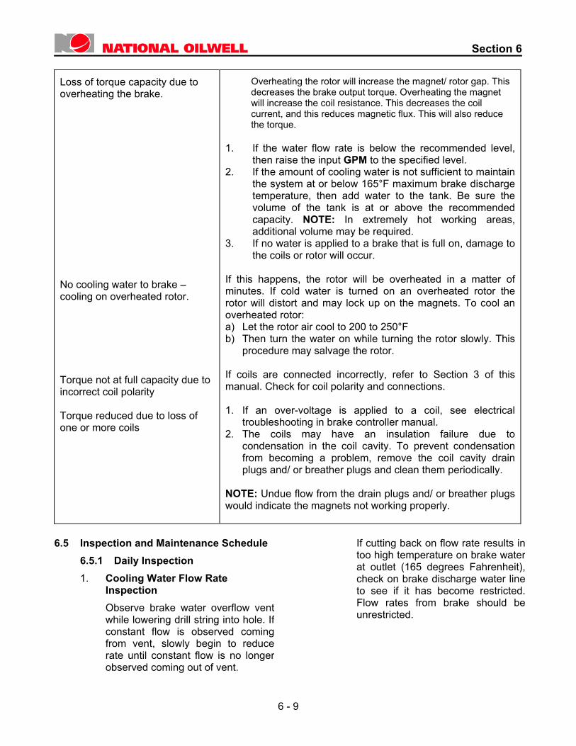
Loss of torque capacity due to overheating the brake. No cooling water to brake – cooling on overheated rotor. Torque not at full capacity due to incorrect coil polarity Torque reduced due to loss of one or more coils
Overheating the rotor will increase the magnet/ rotor gap. This decreases the brake output torque. Overheating the magnet will increase the coil resistance. This decreases the coil current, and this reduces magnetic flux. This will also reduce the torque.
1. If the water flow rate is below the recommended level,
then raise the input GPM to the specified level. 2. If the amount of cooling water is not sufficient to maintain
the system at or below 165°F maximum brake discharge temperature, then add water to the tank. Be sure the volume of the tank is at or above the recommended capacity. NOTE: In extremely hot working areas, additional volume may be required.
3. If no water is applied to a brake that is full on, damage to the coils or rotor will occur.
If this happens, the rotor will be overheated in a matter of minutes. If cold water is turned on an overheated rotor the rotor will distort and may lock up on the magnets. To cool an overheated rotor: a) Let the rotor air cool to 200 to 250°F b) Then turn the water on while turning the rotor slowly. This
procedure may salvage the rotor. If coils are connected incorrectly, refer to Section 3 of this manual. Check for coil polarity and connections. 1. If an over-voltage is applied to a coil, see electrical
troubleshooting in brake controller manual. 2. The coils may have an insulation failure due to
condensation in the coil cavity. To prevent condensation from becoming a problem, remove the coil cavity drain plugs and/ or breather plugs and clean them periodically.
NOTE: Undue flow from the drain plugs and/ or breather plugs would indicate the magnets not working properly.
6.5 Inspection and Maintenance Schedule 6.5.1 Daily Inspection 1. Cooling Water Flow Rate
Inspection Observe brake water overflow ventwhile lowering drill string into hole. Ifconstant flow is observed comingfrom vent, slowly begin to reducerate until constant flow is no longerobserved coming out of vent.
If cutting back on flow rate results in too high temperature on brake water at outlet (165 degrees Fahrenheit), check on brake discharge water line to see if it has become restricted. Flow rates from brake should be unrestricted.
6 - 9
Section 6
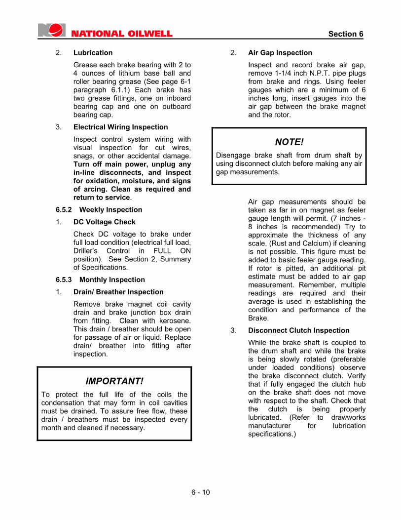
2. Lubrication
Grease each brake bearing with 2 to4 ounces of lithium base ball androller bearing grease (See page 6-1 paragraph 6.1.1) Each brake hastwo grease fittings, one on inboardbearing cap and one on outboardbearing cap.
3. Electrical Wiring Inspection Inspect control system wiring withvisual inspection for cut wires,snags, or other accidental damage.Turn off main power, unplug anyin-line disconnects, and inspectfor oxidation, moisture, and signsof arcing. Clean as required andreturn to service.
6.5.2 Weekly Inspection 1. DC Voltage Check
Check DC voltage to brake underfull load condition (electrical full load,Driller’s Control in FULL ONposition). See Section 2, Summaryof Specifications.
6.5.3 Monthly Inspection 1. Drain/ Breather Inspection
Remove brake magnet coil cavitydrain and brake junction box drainfrom fitting. Clean with kerosene.This drain / breather should be openfor passage of air or liquid. Replacedrain/ breather into fitting afterinspection.
IMPORTANT! To protect the full life of the coils the condensation that may form in coil cavities must be drained. To assure free flow, these drain / breathers must be inspected every month and cleaned if necessary.
2. Air Gap Inspection Inspect and record brake air gap, remove 1-1/4 inch N.P.T. pipe plugs from brake and rings. Using feeler gauges which are a minimum of 6 inches long, insert gauges into the air gap between the brake magnet and the rotor.
NOTE! Disengage brake shaft from drum shaft by using disconnect clutch before making any air gap measurements.
Air gap measurements should be taken as far in on magnet as feeler gauge length will permit. (7 inches -8 inches is recommended) Try to approximate the thickness of any scale, (Rust and Calcium) if cleaning is not possible. This figure must be added to basic feeler gauge reading. If rotor is pitted, an additional pit estimate must be added to air gap measurement. Remember, multiple readings are required and their average is used in establishing the condition and performance of the Brake.
3. Disconnect Clutch Inspection While the brake shaft is coupled to the drum shaft and while the brake is being slowly rotated (preferable under loaded conditions) observe the brake disconnect clutch. Verify that if fully engaged the clutch hub on the brake shaft does not move with respect to the shaft. Check that the clutch is being properly lubricated. (Refer to drawworks manufacturer for lubrication specifications.)
6 - 10
Section 6
6.5.4 Quarterly Inspection 1. Voltage and Resistance Check
Check brake coil voltages at brakejunction box as described in voltagecheck. After voltage check iscomplete (see 6.5.2), turn off mainsupply voltage to brake controlsystem. Disconnect each coil fromthe electrical control system byremoving coil leads from theirinstalled position in brake junctionbox. The coils should read 5megohms or higher to ground whenchecked with a 500 Volt DC meggerelectrical insulation tester.
NOTE! Remove only one set of leads at a time, for example, F1 and F2. Mark their position carefully; check the coil and then return the leads to their exact same position. Failure to return all leads to their correct position could result in incorrect polarity which would seriously decrease the braking effort. Readings for the individual coils should be as listed under coil resistance in summary of specifications. See Section 2.
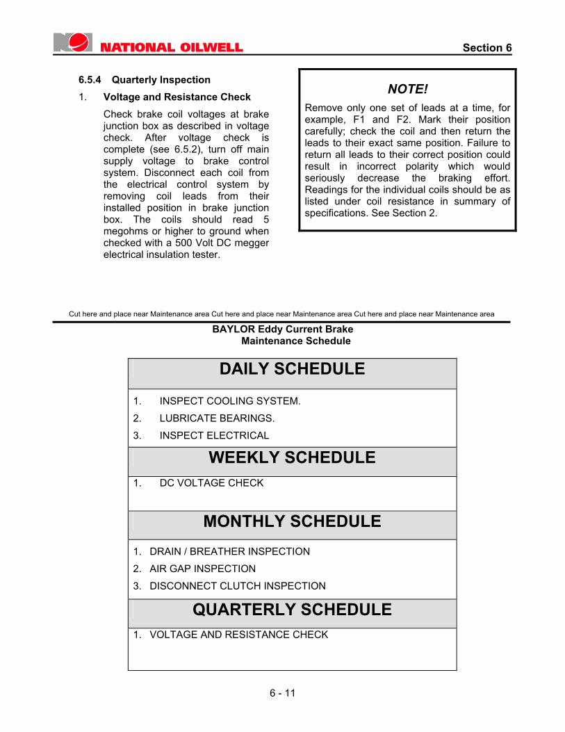
Cut here and place near Maintenance area Cut here and place near Maintenance area Cut here and place near Maintenance area BAYLOR Eddy Current Brake
Maintenance Schedule
DAILY SCHEDULE
1. INSPECT COOLING SYSTEM. 2. LUBRICATE BEARINGS. 3. INSPECT ELECTRICAL
WEEKLY SCHEDULE 1. DC VOLTAGE CHECK
MONTHLY SCHEDULE 1. DRAIN / BREATHER INSPECTION 2. AIR GAP INSPECTION 3. DISCONNECT CLUTCH INSPECTION
QUARTERLY SCHEDULE 1. VOLTAGE AND RESISTANCE CHECK
6 - 11

Section 7
Parts and Supplies
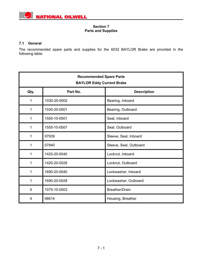
7.1 General The recommended spare parts and supplies for the 6032 BAYLOR Brake are provided in the following table:
Recommended Spare Parts BAYLOR Eddy Current Brake
Qty. Part No. Description
1 1030-20-0002 Bearing, Inboard
1 1030-20-0001 Bearing, Outboard
1 1555-10-0001 Seal, Inboard
1 1555-10-0007 Seal, Outboard
1 07939 Sleeve, Seal, Inboard
1 07940 Sleeve, Seal, Outboard
1 1420-20-0040 Locknut, Inboard
1 1420-20-0028 Locknut, Outboard
1 1690-20-0040 Lockwasher, Inboard
1 1690-20-0028 Lockwasher, Outboard
5 1075-10-0003 Breather/Drain
4 06614 Housing, Breather
7 - 1

Section 8
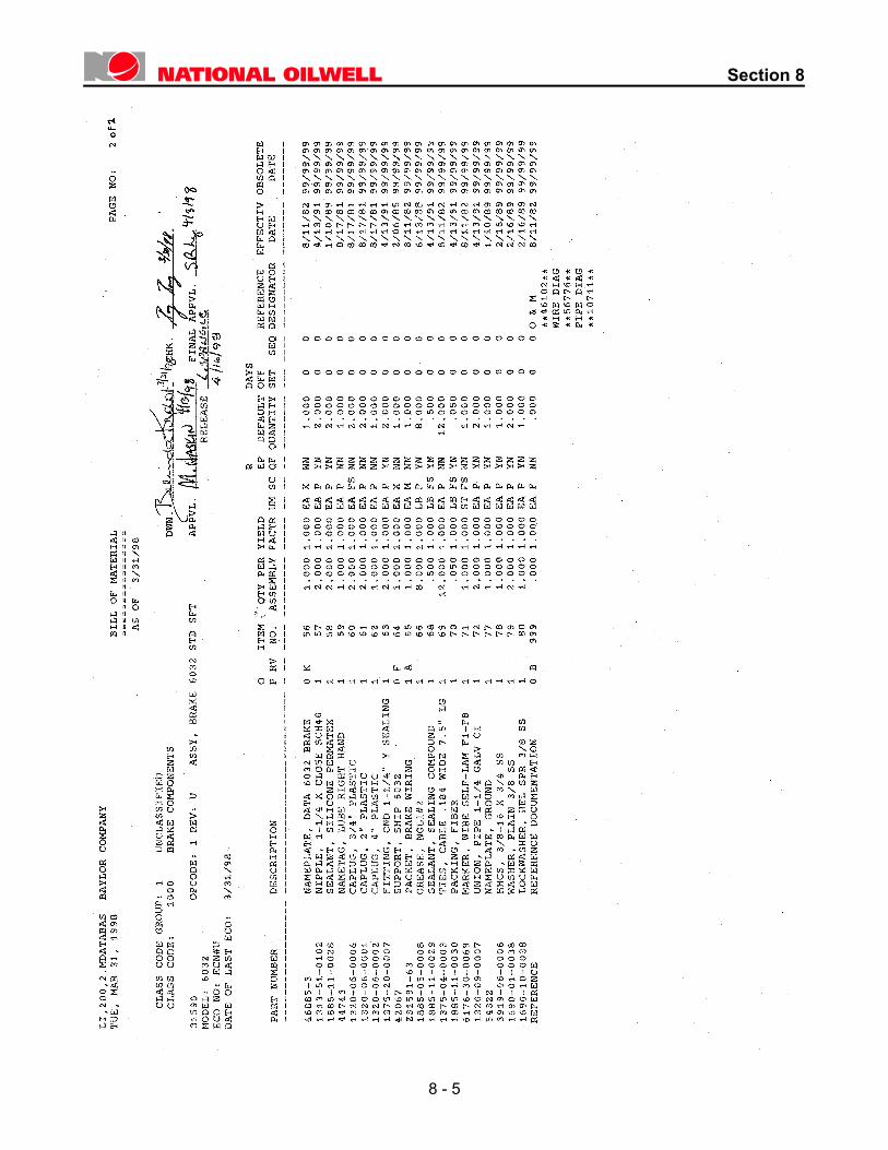
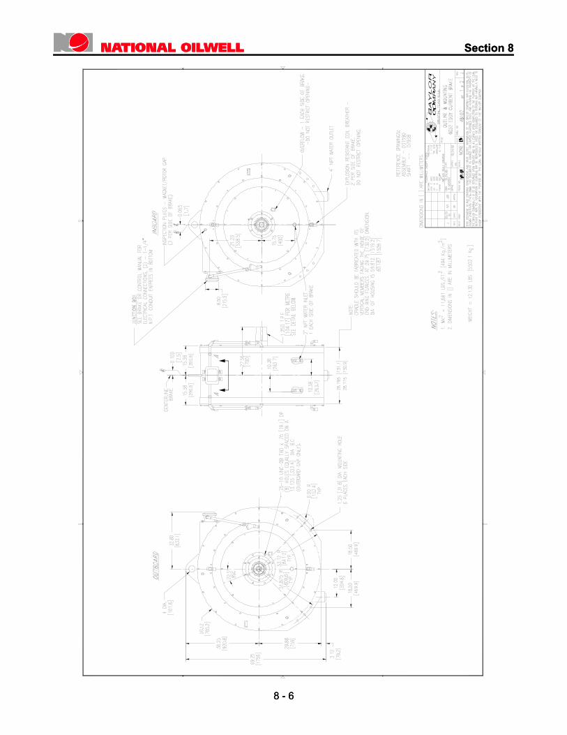
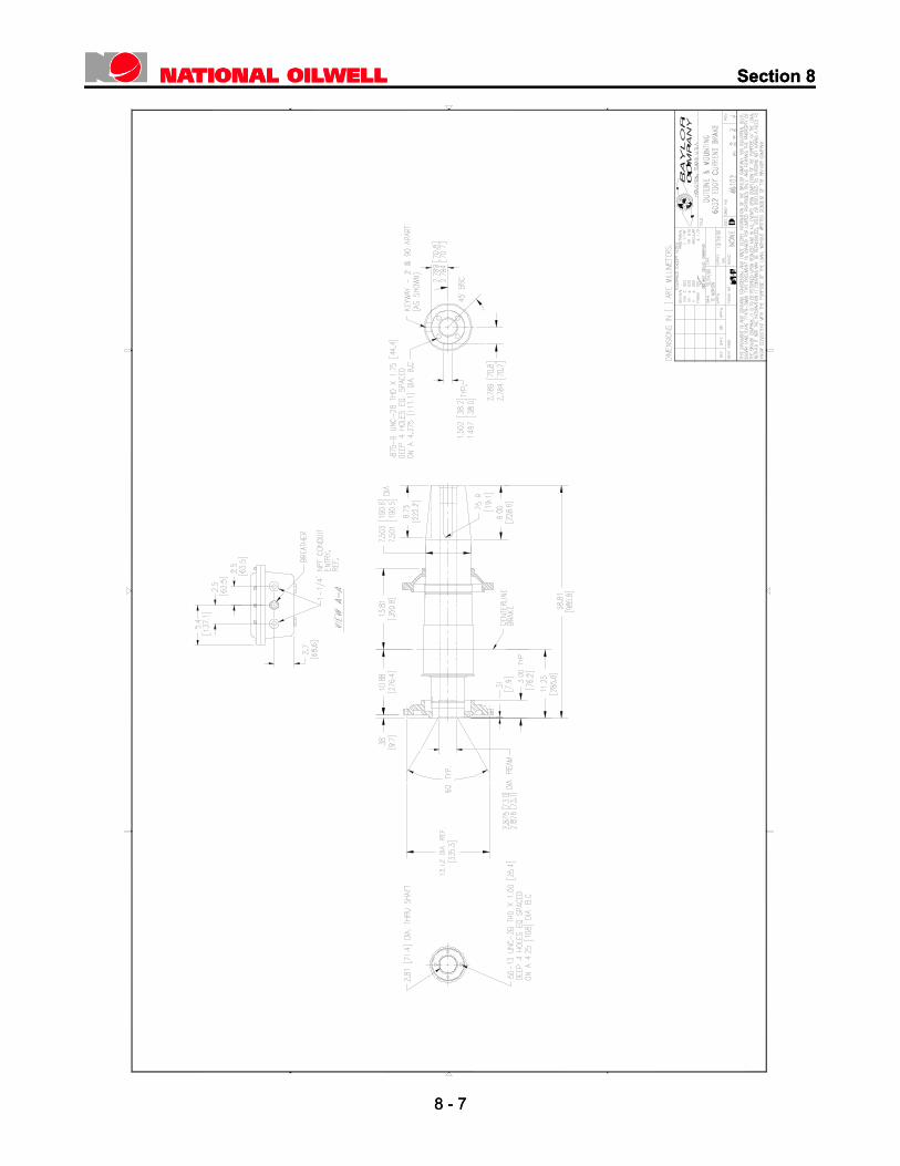
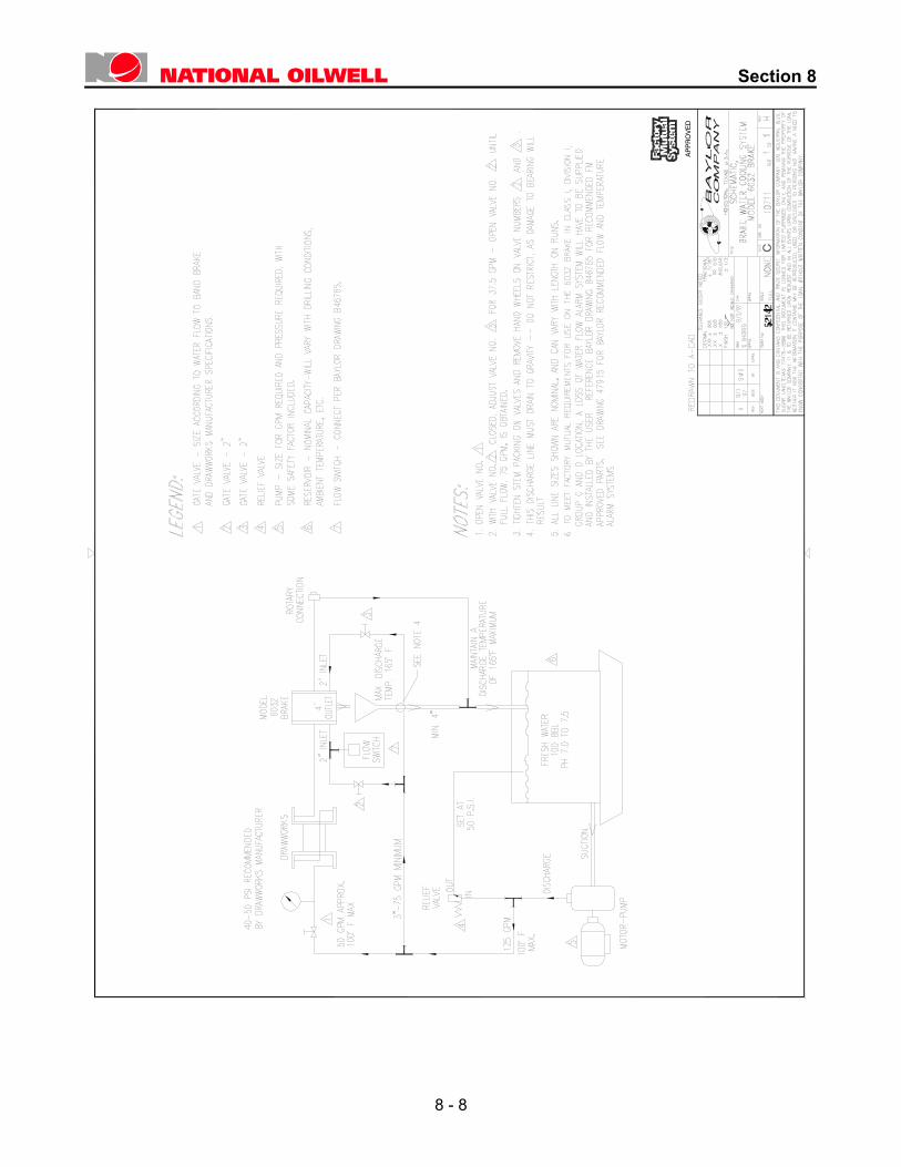
Drawings – 6032 Brake
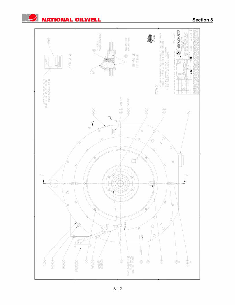
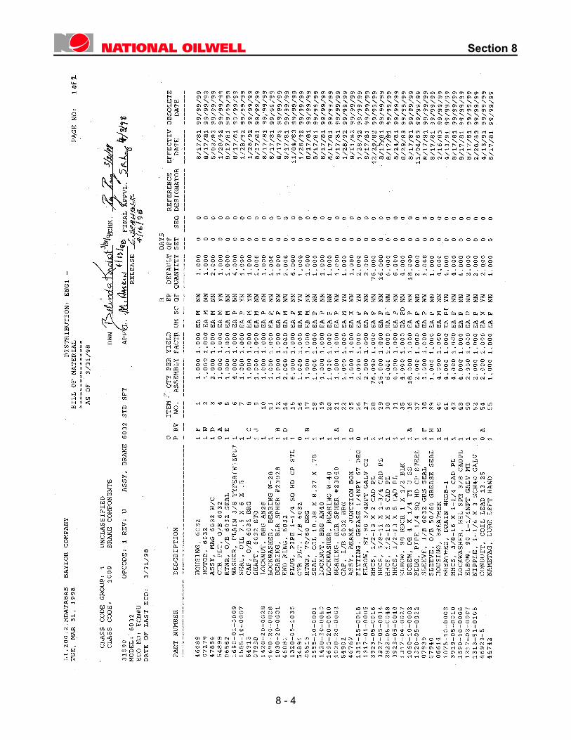
8.1 Drawing List D31590 ............................................................................. Assembly – Model 6032 Eddy Current BrakeB/M31590 .............................................................Bill of Material – 6032 Eddy Current Brake AssemblyD46102 ......................................................................Outline and Mounting – 6032 Eddy Current BrakeC10711 ................................................................................. Schematic – Brake Water Cooling System
8 - 1
Section 8
8 - 2
APPROVED

Section 8
8 - 3
APPROVED
Section 8
8 - 4
Section 8
8 - 5
Section 8
Section 8
8 - 6
8 - 6
Section 8
Section 8
8 - 7
8 - 7
Section 8
APPROVED
8 - 8
Related Documents