1419 / J-241 / Renovation of Hightower Library 00 9111 - 1 ADDENDUM NUMBER 1 SECTION 00 9111 ADDENDUM NUMBER 1 PARTICULARS 1.01 DATE: 06/26/15 1.02 PROJECT: RENOVATION OF HIGHTOWER LIBRARY 1.03 OWNER'S PROJECT NUMBER: 1419 / J-241 TO: PROSPECTIVE BIDDERS: 2.01 THIS ADDENDUM FORMS A PART OF THE CONTRACT DOCUMENTS AND MODIFIES THE ORIGINAL PROCUREMENT DOCUMENTS DATED 04/29/15, WITH AMENDMENTS AND ADDITIONS NOTED BELOW. 2.02 ACKNOWLEDGE RECEIPT OF THIS ADDENDUM IN THE SPACE PROVIDED IN THE BID FORM. FAILURE TO DO SO MAY DISQUALIFY THE BIDDER. 2.03 THIS ADDENDUM CONSISTS OF 122 PAGE(S) AND THE FOLLOWING DRAWINGS: CHANGES TO THE PROJECT MANUAL - INTRODUCTORY INFORMATION: 3.01 SECTION 00 0110 - TABLE OF CONTENTS A. Revised to reflect changes per Addendum Number 1. 3.02 SECTION 00 9111 – ADDENDUM NUMBER 1 A. Included in project manual. CHANGES TO THE PROJECT MANUAL - SPECIFICATIONS: 4.01 SECTION 01 5000 – TEMPORARY FACILITIES AND CONTROLS A. Revised to indicate the requirement for the Contractor to meter the utilities during the duration of the project. B. Revised to indicate that the fencing is to be temporary with free standing posts, and not drilled into the existing paving surfaces. 4.02 SECTION 03 4900 – GLASS-FIBER REINFORCED CONCRETE A. Revised to include ARC LTD and Fiblast as an acceptable manufacturers. 4.03 SECTION 04 2000 – UNIT MASONRY A. Revised to clarify that new brick is to be provided by the Contractor if the salvaged quantity is less than the quantity needed. 4.04 SECTION 06 4216 – WOOD-VENEER PANELING A. Revised wood panel type from particleboard to Medium Density Fiberboard. 4.05 SECTION 07 4264 – METAL COMPOSITE MATERIAL WALL PANELS A. Revised to include Peachtree Protective Covers, Inc. as an acceptable manufacturer. 4.06 SECTION 08 1416 – FLUSH WOOD DOORS A. Revised to include Oshkosh Door Company as an approved manufacturer 4.07 SECTION 08 7100 – DOOR HARDWARE A. Revised to include BEST as an acceptable manufacturer. B. Revised to include specifications for Exit Devices. 4.08 SECTION 08 7113 – AUTOMATIC OPERATORS A. Revised to indicate door 103 in lieu of 105 under HW-04.

Welcome message from author
This document is posted to help you gain knowledge. Please leave a comment to let me know what you think about it! Share it to your friends and learn new things together.
Transcript

1419 / J-241 / Renovation of Hightower Library
00 9111 - 1 ADDENDUM NUMBER 1
SECTION 00 9111
ADDENDUM NUMBER 1
PARTICULARS
1.01 DATE: 06/26/15
1.02 PROJECT: RENOVATION OF HIGHTOWER LIBRARY
1.03 OWNER'S PROJECT NUMBER: 1419 / J-241
TO: PROSPECTIVE BIDDERS:
2.01 THIS ADDENDUM FORMS A PART OF THE CONTRACT DOCUMENTS AND MODIFIES THE ORIGINAL PROCUREMENT DOCUMENTS DATED 04/29/15, WITH AMENDMENTS AND ADDITIONS NOTED BELOW.
2.02 ACKNOWLEDGE RECEIPT OF THIS ADDENDUM IN THE SPACE PROVIDED IN THE BID FORM. FAILURE TO DO SO MAY DISQUALIFY THE BIDDER.
2.03 THIS ADDENDUM CONSISTS OF 122 PAGE(S) AND THE FOLLOWING DRAWINGS:
CHANGES TO THE PROJECT MANUAL - INTRODUCTORY INFORMATION:
3.01 SECTION 00 0110 - TABLE OF CONTENTS
A. Revised to reflect changes per Addendum Number 1.
3.02 SECTION 00 9111 – ADDENDUM NUMBER 1
A. Included in project manual.
CHANGES TO THE PROJECT MANUAL - SPECIFICATIONS:
4.01 SECTION 01 5000 – TEMPORARY FACILITIES AND CONTROLS
A. Revised to indicate the requirement for the Contractor to meter the utilities during the duration of the project.
B. Revised to indicate that the fencing is to be temporary with free standing posts, and not drilled into the existing paving surfaces.
4.02 SECTION 03 4900 – GLASS-FIBER REINFORCED CONCRETE
A. Revised to include ARC LTD and Fiblast as an acceptable manufacturers.
4.03 SECTION 04 2000 – UNIT MASONRY
A. Revised to clarify that new brick is to be provided by the Contractor if the salvaged quantity is less than the quantity needed.
4.04 SECTION 06 4216 – WOOD-VENEER PANELING
A. Revised wood panel type from particleboard to Medium Density Fiberboard.
4.05 SECTION 07 4264 – METAL COMPOSITE MATERIAL WALL PANELS
A. Revised to include Peachtree Protective Covers, Inc. as an acceptable manufacturer.
4.06 SECTION 08 1416 – FLUSH WOOD DOORS
A. Revised to include Oshkosh Door Company as an approved manufacturer
4.07 SECTION 08 7100 – DOOR HARDWARE
A. Revised to include BEST as an acceptable manufacturer.
B. Revised to include specifications for Exit Devices.
4.08 SECTION 08 7113 – AUTOMATIC OPERATORS
A. Revised to indicate door 103 in lieu of 105 under HW-04.

100% CONSTRUCTION DOCUMENTS
1419 / J-241 / Renovation of Hightower Library
00 9111 - 2 ADDENDUM NUMBER 1 06/26/15
4.09 SECTION 09 8400 – ACOUSTIC ROOM COMPONENTS
A. Revised to include Fiberglass panels as an acceptable material.
B. Revised to indicate the scheduled fabric covering.
4.10 SECTION 10 1400 - SIGNAGE
A. Revised to include the referenced Sign Guideline Manual.
4.11 SECTION 12 2400 – ROLLER WINDOW SHADES
A. Revised to include substitutions.
4.12 SECTION 22 4000 – PLUMBING FIXTURES AND TRIM
A. Revised to coordinate water closet mounting types.
4.13 SECTION 23 0923 – BUILDING AUTOMATION AND TEMPERATURE CONTROL SYSTEMS
A. Revised to coordinate control system.

100% CONSTRUCTION DOCUMENTS
1419 / J-241 / Renovation of Hightower Library
00 9111 - 3 ADDENDUM NUMBER 1 06/26/15
CHANGES TO THE DRAWINGS:
5.01 DRAWING G001 – Cover Sheet
A. Revised to coordinate drawing list with Addendum #1.
5.02 DRAWING G002 – General Notes, Legend & Keynote List
A. Revised to reflect the correct keynote list.
5.03 DRAWING L-2 – Site Plan
A. Revised to coordinate the elevations at the door.
5.04 DRAWING L-3 – Grading and Drainage Plan
A. Revised to coordinate the elevations at the door.
5.05 DRAWING L-5 – Site Details
A. Revised to include step details to coordinate the elevations at the door.
5.06 DRAWING A101 – Main Level Renovated Plan
A. Revised to coordinate location of fire alarm pull station.
B. Revised to coordinate dimension of storefront wall.
5.07 DRAWING A102 – Second Level Renovated Plan
A. Revised to coordinate location of fire alarm pull station.
5.08 DRAWING A200 – Building Elevation
A. Revised to include a note about the existing condition at the brick support lintel.
5.09 DRAWING A222 – Monumental Stair Wall Sections
A. Revised to coordinate location of fire alarm pull station with electrical drawings.
5.10 DRAWING A402 – Second Level Reflected Ceiling Plan
A. Revised indicate the roller shades in room 226 correctly.
5.11 DRAWING A506 – Shutter and Partition Details
A. Revised to correctly keynote products.
5.12 DRAWING A511 – Flashing Details
A. Revised to correctly keynote products.
5.13 DRAWING AI001 – Finish Schedule
A. Revised the tile basis of design product.
5.14 DRAWING AI102 – Second Level – Finish Plan
A. Revised to indicate floor finishes in rooms 226 & 227.
5.15 DRAWING M501 – Mechanical Equipment Sequences
A. Revised control sequences note about existing building controls.
5.16 DRAWING P000 – Plumbing Notes, Schedules and Details
A. Revised to indicate the first floor water closets as floor mounted and the second floor as wall hung.
5.17 DRAWING P201 – Plumbing S, W&V Part Plan and Risers
A. Revised to coordinate the riser diagram with the mounting types.
5.18 DRAWING E001 – Symbols Legend & Notes
A. Revised fire alarm symbols.
5.19 DRAWING E201 – Panel Schedules
A. Revised to include note about breaker on panel schedule.

100% CONSTRUCTION DOCUMENTS
1419 / J-241 / Renovation of Hightower Library
00 9111 - 4 ADDENDUM NUMBER 1 06/26/15
5.20 DRAWING E500 – Main Level Special Systems Plan
A. Revised to include additional devices, pull stations and revised notes.
5.21 DRAWING E501 – Second Level Special Systems Plan
A. Revised to include additional devices, pull stations and revised notes.
END OF ADDENDUM NUMBER 1
1419 / J-241 / Renovation of Hightower Library
00 0110 - 1 TABLE OF CONTENTS
SECTION 00 0110
TABLE OF CONTENTS
PROCUREMENT AND CONTRACTING REQUIREMENTS
1.01 DIVISION 00 -- PROCUREMENT AND CONTRACTING REQUIREMENTS
A. 00 0107 - Seals Page
B. 00 0110 - Table of Contents, revised 06/26/15
C. 00 1113 - Advertisement for Bids
D. 00 4100 - Bid Form
E. 00 5000 - Contracting Forms and Supplements
F. 00 9111 – Addendum Number 1, 06/26/15
SPECIFICATIONS
2.01 DIVISION 01 -- GENERAL REQUIREMENTS
A. 01 1000 - Summary
B. 01 2300 - Alternates
C. 01 3000 - Administrative Requirements
D. 01 3330 - Structural Submittals
E. 01 4000 - Quality Requirements
F. 01 4525 – Structural Testing/Inspection Agency Services
G. 01 5000 - Temporary Facilities and Controls, revised 06/26/15
H. 01 5639 – Tree Protection
I. 01 6000 - Product Requirements
J. 01 6116 - Volatile Organic Compound (VOC) Content Restrictions
K. 01 7000 - Execution and Closeout Requirements
L. 01 7800 - Closeout Submittals
M. 01 7900 - Demonstration and Training
2.02 DIVISION 02 -- EXISTING CONDITIONS
A. 02 4100 - Demolition
2.03 DIVISION 03 -- CONCRETE
A. 03 1000 - Concrete Formwork
B. 03 2000 - Concrete Reinforcing
C. 03 3000 - Cast-in-Place Concrete
D. 03 3511 - Concrete Floor Finishes
E. 03 4900 - Glass-Fiber Reinforced Concrete, revised 06/26/15
2.04 DIVISION 04 -- MASONRY
A. 04 0100 - Maintenance of Masonry
B. 04 2000 - Unit Masonry, revised 06/26/15
2.05 DIVISION 05 -- METALS
A. 05 1000 - Structural Steel Framing
B. 05 5000 - Metal Fabrications
C. 05 5213 - Pipe and Tube Railings
D. 05 7000 - Decorative Metal

100% CONSTRUCTION DOCUMENTS
1419 / J-241 / Renovation of Hightower Library
00 0110 - 2 TABLE OF CONTENTS 04/29/15
2.06 DIVISION 06 -- WOOD, PLASTICS, AND COMPOSITES
A. 06 1000 - Rough Carpentry
B. 06 2000 - Finish Carpentry
C. 06 4100 - Architectural Wood Casework
D. 06 4216 - Wood-Veneer Paneling, revised 06/26/15
2.07 DIVISION 07 -- THERMAL AND MOISTURE PROTECTION
A. 07 2100 - Thermal Insulation
B. 07 2500 - Weather Barriers
C. 07 4264 - Metal Composite Material Wall Panels, revised 06/26/15
D. 07 6200 - Sheet Metal Flashing and Trim
E. 07 7100 - Roof Specialties
F. 07 8400 - Firestopping
G. 07 9005 - Joint Sealers
2.08 DIVISION 08 -- OPENINGS
A. 08 1113 - Hollow Metal Doors and Frames
B. 08 1416 - Flush Wood Doors, revised 06/26/15
C. 08 3100 - Access Doors and Panels
D. 08 3323 - Side and Overhead Coiling Fire Rated Doors and Shutters
E. 08 3326 - Overhead Coiling Grilles
F. 08 4313 - Aluminum-Framed Storefronts
G. 08 7100 - Door Hardware, revised 06/26/15
H. 08 7113 –Automatic Operator, revised 06/26/15
IH. 08 8000 - Glazing
2.09 DIVISION 09 -- FINISHES
A. 09 2116 - Gypsum Board Assemblies
B. 09 2400 - Portland Cement Plastering
C. 09 3000 - Tiling
D. 09 5100 - Acoustical Ceilings
E. 09 6500 - Resilient Flooring
F. 09 6813 - Tile Carpeting
G. 09 8400 - Acoustic Components, revised 06/26/15
H. 09 9000 - Painting and Coating
2.10 DIVISION 10 -- SPECIALTIES
A. 10 1101 - Visual Display Boards
B. 10 1400 - Signage, revised 06/26/15
C. 10 2113 - Plastic Toilet Compartments
D. 10 2226 - Folding Panel Partitions
E. 10 2601 - Wall and Corner Guards
F. 10 2800 - Toilet, Bath, and Laundry Accessories
G. 10 4400 - Fire Protection Specialties
H. 10 5617 - Wall Mounted Standards and Shelving
2.11 DIVISION 11 -- EQUIPMENT

100% CONSTRUCTION DOCUMENTS
1419 / J-241 / Renovation of Hightower Library
00 0110 - 3 TABLE OF CONTENTS 04/29/15
A. 11 3100 - Residential Appliances
B. 11 5213 - Projection Screens
C. 11 5400 - Library Detection System
D. 11 5420 - Library Self Check System
2.12 DIVISION 12 -- FURNISHINGS
A. 12 2400 - Roller Window Shades, revised 06/26/15
B. 12 4813 - Entrance Floor Mats and Frames
2.13 DIVISION 13 -- SPECIAL CONSTRUCTION
2.14 DIVISION 14 -- CONVEYING EQUIPMENT
2.15 DIVISION 21 -- FIRE SUPPRESSION
A. 21 0000 - Fire Suppression
2.16 DIVISION 22 -- PLUMBING
A. 22 0010 - General Provisions – Plumbing
B. 22 0100 - Operation and Maintenance of Plumbing
C. 22 0500 - Common Work Results for Plumbing
D. 22 0523 - Plumbing Valves and Strainers
E. 22 0553 - Identification for Plumbing Piping and Equipment
F. 22 0700 - Plumbing Insulation
G. 22 1000 - Pipe, Fittings, and Accessories – Plumbing
H. 22 1005 - Plumbing Piping and Drainage Accessories
I. 22 4000 - Plumbing Fixtures and Trim, revised 06/26/15
2.17 DIVISION 23 -- HEATING, VENTILATING, AND AIR-CONDITIONING (HVAC)
A. 23 0010 - General Provisions – HVAC
B. 23 0100 - Operation and Maintenance of HVAC Systems
C. 23 0500 - Common Work Results for HVAC
D. 23 0520 – Pressure Gauges and Valves
E. 23 0521 – Temperature Gauges and Test Wells
F. 23 0523 - HVAC Valves and Strainers
G. 23 0529 - Equipment Supports
H. 23 0553 - Identification for HVAC Piping and Equipment
I. 23 0593 - Testing Balancing and Adjusting
J. 23 0700 - HVAC Insulation
K. 23 0923 - Building Automation and Temperature Control System, revised 06/26/15
L. 23 2000 - Pipe, Fittings, and Accessories – HVAC
M. 23 2113 - Hydronic Piping
N. 23 2114 - Hydronic Specialties
O. 23 2124 – Pumps – End Suction
P. 23 2300 - Refrigerant Piping and Accessories
Q. 23 3100 - Ductwork
R. 23 3315 - Fire, Smoke, and Combination Fire Smoke Dampers
S. 23 3400 - Fans
T. 23 3616 - Variable Volume Terminals
100% CONSTRUCTION DOCUMENTS
1419 / J-241 / Renovation of Hightower Library
00 0110 - 4 TABLE OF CONTENTS 04/29/15
U. 23 3713 - Grilles, Registers, and Diffusers
V. 23 8126 - Direct Expansion Equipment
2.18 DIVISION 26 -- ELECTRICAL
A. 26 00 00 - Electrical General Provisions
B. 26 05 00 - Basic Materials and Methods
C. 26 05 19 - 600V Building Wire and Cable
D. 26 05 26 - Grounding System
E. 26 05 33 - Conduit
F. 26 05 34 - Boxes
G. 26 05 48 - Seismic Restraints
H. 26 05 53 - Electrical Identification
I. 26 05 73 - Protective Device Coordination Study
J. 26 22 00 - Dry-type Power Transformers
K. 26 24 00 - New Overcurrent Devices in Existing Equipment
L. 26 24 14 - Power Distribution Panelboards
M. 26 24 16 - Branch Circuit Panelboards
N. 26 27 00 - Miscellaneous Distribution Equipment
O. 26 27 26 - Wiring Devices
P. 26 29 00 - Motor Control
Q. 26 41 13 - Lightning Protection System
R. 26 50 00 - Luminaires
2.19 DIVISION 27 -- COMMUNICATIONS
2.20 DIVISION 28 -- ELECTRONIC SAFETY AND SECURITY
A. 28 13 00 - Card Access Control System
B. 28 16 00 - Intrusion Detection System
C. 28 31 00 - Fire Alarm System
2.21 DIVISION 31 -- EARTHWORK
A. 31 1000 – Site Clearing
B. 31 2000 - Earthwork
C. 31 2301 - Excavating, Backfilling, and Compacting for Structures
2.22 DIVISION 32 -- EXTERIOR IMPROVEMENTS
A. 32 1216 – Asphalt Paving
B. 32 1313 – Concrete Paving and Curbs
C. 32 1400 – Unit Pavers
D. 32 9200 – Lawns and Grasses
E. 32 9300 – Landscape Plantings
2.23 DIVISION 33 -- UTILITIES
A. 33 4100 – Storm and Utility Drainage Piping
END OF TABLE OF CONTENTS

100% CONSTRUCTION DOCUMENTS
1419 / J-241 / Renovation of Hightower Library
00 0110 - 5 TABLE OF CONTENTS 04/29/15

1419 / J-241 / Renovation of Hightower Library
01 5000 - 1 TEMPORARY FACILITIES AND CONTROLS
06/26/15 Addendum #1
SECTION 01 5000
TEMPORARY FACILITIES AND CONTROLS
PART 1 GENERAL
1.01 SECTION INCLUDES
A. Temporary utilities.
B. Temporary Controls: Barriers, enclosures, and fencing.
C. Security requirements.
D. Vehicular access and parking.
E. Waste removal facilities and services.
1.02 TEMPORARY UTILITIES - SEE SECTION 01 5100
A. Owner may decide to allow use of the building's existing facilities provided that an agreement can be developed with the Contractor for back-charging costs at an acceptable or published rate. At a minimum, where the Owner owns the utility, the Contractor shall pay for the College for the use of these utilities. The College and the Board of Regents own the following:
1. Communications
2. Electric
3. Water
4. Sanitary Sewer
5. Storm Sewer
6. Natural Gas
B. Provide and pay for all electrical power, lighting, water, heating and cooling, and ventilation required for construction purposes. Contractor is to meter these utilities and reimburse the Owner at prevailing rates for the utilities used during the construction period.
1.03 BARRIERS
A. Provide barriers to prevent unauthorized entry to construction areas, to prevent access to areas that could be hazardous to workers or the public, to allow for owner's use of site and to protect existing facilities and adjacent properties from damage from construction operations and demolition.
B. Provide barricades and covered walkways required by governing authorities for public rights-of-way and for public access to existing building.
C. Protect non-owned vehicular traffic, stored materials, site, and structures from damage.
1.04 FENCING
A. Provide temporary 6 foot (1.8 m) high fence around construction site; equip with vehicular and pedestrian gates with locks. Fence posts are to be freestanding and are not to be drilled into existing paving surfaces.
B. Provide tree protection fencing around trees within construction laydown area used, not specifically indicated in the drawings.
1.05 SECURITY
A. Provide security and facilities to protect Work, existing facilities, and Owner's operations from unauthorized entry, vandalism, or theft.
B. Coordinate with Owner's security program.
1.06 VEHICULAR ACCESS AND PARKING
A. Comply with regulations relating to use of streets and sidewalks, access to emergency facilities, and access for emergency vehicles.
B. Coordinate access and haul routes with governing authorities and Owner.
C. Provide and maintain access to fire hydrants, free of obstructions.
100% CONSTRUCTION DOCUMENTS
1419 / J-241 / Renovation of Hightower Library
01 5000 - 2 TEMPORARY FACILITIES AND CONTROLS
04/29/15
D. Provide means of removing mud from vehicle wheels before entering streets.
E. Provide temporary parking areas to accommodate construction personnel. When site space is not adequate, provide additional off-site parking.
1.07 WASTE REMOVAL
A. Provide waste removal facilities and services as required to maintain the site in clean and orderly condition.
B. Provide containers with lids. Remove trash from site periodically.
C. If materials to be recycled or re-used on the project must be stored on-site, provide suitable non-combustible containers; locate containers holding flammable material outside the structure unless otherwise approved by the authorities having jurisdiction.
D. Open free-fall chutes are not permitted. Terminate closed chutes into appropriate containers with lids.
1.08 REMOVAL OF UTILITIES, FACILITIES, AND CONTROLS
A. Remove temporary utilities, equipment, facilities, materials, prior to Substantial Completion inspection.
B. Remove underground installations to a minimum depth of 2 feet (600 mm). Grade site as indicated.
C. Clean and repair damage caused by installation or use of temporary work.
PART 2 PRODUCTS - NOT USED
PART 3 EXECUTION - NOT USED
END OF SECTION
1419 / J-241 / Renovation of Hightower Library
03 4900 - 1 GLASS-FIBER REINFORCED CONCRETE
06/26/15 Addendum #1
SECTION 03 4900
GLASS-FIBER REINFORCED CONCRETE
PART 1 GENERAL
1.01 SECTION INCLUDES
A. Architectural precast glass-fiber-reinforced concrete column covers.
1.02 RELATED REQUIREMENTS
A. Section 07 2100 - Thermal Insulation: Integral insulation.
B. Section 09 2116 - Gypsum Board Assemblies: Metal framing.
C. Section 09 9000 – Painting and Coating: Field painting and sealing prior to paintin.
1.03 REFERENCE STANDARDS A. ASTM C 150 - Standard Specification for Portland Cement; 1999a. B. ASTM E 84 - Standard Test Method for Surface Burning Characteristics of Building
Materials; 1999. C. ASTM G 23 - Standard Practice for Operating Light-Exposure Apparatus (Carbon-Arc Type)
With and Without Water for Exposure of Nonmetallic Materials; 1996.
1.04 ADMINISTRATIVE REQUIREMENTS
A. Preinstallation Meeting: Convene one week before starting work of this section.
1.05 SUBMITTALS
A. See Section 01 3000 - Administrative Requirements, for submittal procedures.
B. Shop Drawings: Indicate locations, fabrication details, reinforcement, metal framing details, connection details, dimensions, and relationship to adjacent materials. Provide erection drawings.
C. Manufacturer's Installation Instructions: Indicate surface cleaning instructions.
D. Fabricator Qualifications.
E. Samples: For each custom finish specified, two samples, minimum size 6 inches (150 mm) square, representing actual product, color, and patterns.
1.06 QUALITY ASSURANCE
A. Fabricator Qualifications: Company specializing in performing the work of this section with minimum 5 years of documented experience.
1.07 PROJECT CONDITIONS
A. Coordinate the Work with installation of backup supporting structure.
1.08 DELIVERY, STORAGE, AND HANDLING
A. Handle units to position, consistent with their shape and design. Lift and support only from support points.
B. Blocking and Lateral Support During Transport and Storage: Clean, non-staining, without causing harm to exposed surfaces. Provide temporary lateral support to prevent bowing and warping. Place spacers in same location during transport and site storage.
C. Protect edges of units to prevent staining, chipping, or spalling of concrete.
PART 2 PRODUCTS
2.01 MANUFACTURERS
A. Glass-Fiber-Reinforced Concrete:
1. Stromberg Architectural Products, Inc: www.strombergarchitectural.com.
2. Casting Designs, Inc. www.castingdesignsinc.com.
3. IntexForms, Inc. www.intexforms.com.
4. ARC LTD. www.arcgfrc.com
5. Fiblast LLC. www.fiblast.com

100% CONSTRUCTION DOCUMENTS
1419 / J-241 / Renovation of Hightower Library
03 4900 - 2 GLASS-FIBER REINFORCED CONCRETE
04/29/15 06/26/15 Addendum #1
54. Substitutions: See Section 01 6000 - Product Requirements.
2.02 GLASS-FIBER-REINFORCED CONCRETE FABRICATIONS A. Glass Fiber Reinforced Concrete Fabrications: High density concrete made of ASTM C 150
Portland cement, crushed stone, silica sand, and polymers reinforced with continuous filament glass fiber mat and structural reinforcing as required; asbestos free. 1. Color: As selected from manufacturer's selection. 2. Color: To match Architect's sample. To match color of columns at adjacent Instruction
Complex building. 3. Density: 140 pcf (2240 kg/cu m). 4. Shell Thickness: 3/8” to 3/4 inch (9.5 mm), nominal. 5. Surface Burning Characteristics: Flame spread index of 0, smoke developed index of
5; when tested in accordance with ASTM E 84. Fuel contribution of 3. 6. Weather Resistance: No significant loss in strength or change in appearance after
200 hours accelerated weathering conducted in accordance with ASTM G 23. 7. Flexural Strength: 1000 to 1800 psi (6.9 to 12.4 MPa). 8. Modulus of Elasticity: 1.4x10⁶ to 2.9 x10⁶ 9. Compressive Strength: Over 5000 psi (34 MPa). 10. Variation from Dimensions Indicated on Drawings: Plus and minus 1/8 inch (3 mm),
maximum. 11. Variation from Plane Along Edge or Surface: Plus and minus 1/16 inch per linear foot
(1.5 mm in 300 mm), maximum. 12. Outside Corner Radius: 1/16 inch to 1/8 inch (1.5 to 3 mm). 13. Draft Angle: 3 degrees, minimum, on returns, setbacks, reveals, and grooves. 14. Provide concealed anchorage points for plaster type wire anchors. 15. Provide screwed or bolted anchors with reinforced holes through face of units. 16. Provide anchors and reinforced anchoring points as necessary. 17. Appearance: Ensure exposed-to-view finish surfaces of units are uniform in color and
appearance.
2.03 FABRICATION
A. Place metal framing members in position in mold.
B. Embed anchors, inserts, plates, angles, and other cast-in items as indicated on shop drawings.
C. Fit integral insulation into units for continuous thermal protection of building interior.
D. Fabricate connecting devices, items fit to framing members, fasteners and accessories necessary for proper installation.
E. Locate hoisting devices to permit device removal after erection.
F. Cure units to minimize appearance blemishes such as non-uniformity, staining or surface cracking.
G. Identify each unit with corresponding code on erection drawings, in location not visible in finish work.
H. Exposed Non-Galvanized Steel Components: Clean surfaces of rust, scale, grease, and foreign matter; prime paint in one coat, except surfaces in direct contact with concrete or requiring field welding.
I. Provide block-outs as indicated in the drawings. Coordinate required dimensions with manufacturers.
J. Provide reveals at base and top of column covers, as indicated in the drawings.
PART 3 EXECUTION
3.01 EXAMINATION A. Do not begin installation until substrates have been properly constructed; verify that
substrates are plumb and true. B. If substrate preparation is the responsibility of another installer, notify Architect of
unsatisfactory preparation before proceeding.

100% CONSTRUCTION DOCUMENTS
1419 / J-241 / Renovation of Hightower Library
03 4900 - 3 GLASS-FIBER REINFORCED CONCRETE
04/29/15 06/26/15 Addendum #1
C. Check field dimensions before beginning installation. If dimensions vary too much from
design dimensions for proper installation, notify Architect and wait for instructions before beginning installation.
3.02 ERECTION
A. Coordinate installation with that of structural supports, backup, and opening framing, if any.
B. Erect units without damage to shape or finish. Replace or repair damaged panels.
C. Erect units level and plumb within allowable tolerances.
D. Tape joints and finish in field.
E. Patch exposed anchor points to match color and texture of unit.
3.03 TOLERANCES
A. Maximum Variation from Plane of Location: 1/4 inch in 10 feet and 3/8 inch in 100 feet (6 mm in 3 m and 9 mm in 30 m), non-cumulative.
END OF SECTION
1419 / J-241 / Renovation of Hightower Library
04 2000 - 1 UNIT MASONRY 06/26/15 Addendum #1
SECTION 04 2000
UNIT MASONRY
PART 1 GENERAL
1.01 SECTION INCLUDES
A. Clay Facing Brick.
B. Mortar and Grout.
C. Reinforcement and Anchorage.
D. Flashings.
E. Accessories.
1.02 RELATED REQUIREMENTS
A. Section 02 4100 - Demolition: Reusing salvaged existing brick.
B. Section 03 2000 - Concrete Reinforcing: Reinforcing steel for grouted masonry.
C. Section 05 5000 - Metal Fabrications: Loose steel lintels.
D. Section 07 6200 - Sheet Metal Flashing and Trim: Through-wall masonry flashings.
E. Section 07 9200 - Joint Sealants: Sealing control and expansion joints.
1.03 REFERENCE STANDARDS
A. ACI 530/530.1/ERTA - Building Code Requirements and Specification for Masonry Structures and Related Commentaries; American Concrete Institute International; 2011.
B. ASTM A153/A153M - Standard Specification for Zinc Coating (Hot-Dip) on Iron and Steel Hardware; 2009.
C. ASTM A641/A641M - Standard Specification for Zinc-Coated (Galvanized) Carbon Steel Wire; 2009a.
D. ASTM A1064/A1064M - Standard Specification for Carbon-Steel Wire and Welded Wire Reinforcement, Plain and Deformed, for Concrete; 2013.
E. ASTM C62 - Standard Specification for Building Brick (Solid Masonry Units Made From Clay or Shale); 2013.
F. ASTM C91/C91M - Standard Specification for Masonry Cement; 2012.
G. ASTM C216 - Standard Specification for Facing Brick (Solid Masonry Units Made From Clay or Shale); 2014.
H. ASTM C270 - Standard Specification for Mortar for Unit Masonry; 2012.
1.04 SUBMITTALS
A. See Section 01 3000 - Administrative Requirements, for submittal procedures.
B. Samples: Submit four samples of decorative block units to illustrate color, texture, and extremes of color range.
1.05 QUALITY ASSURANCE
A. Comply with provisions of ACI 530/530.1/ERTA, except where exceeded by requirements of the contract documents.
1.06 DELIVERY, STORAGE, AND HANDLING
A. Deliver, handle, and store masonry units by means that will prevent mechanical damage and contamination by other materials.
PART 2 PRODUCTS
2.01 BRICK UNITS
A. Facing Brick: ASTM C216, Type FBS, Grade SW. Existing brick to be salvaged where removed to make new openings for storefront. New brick is to be provided, if the amount salvaged does

100% CONSTRUCTION DOCUMENTS
1419 / J-241 / Renovation of Hightower Library
04 2000 - 2 UNIT MASONRY 04/29/15 06/26/15 Addendum #1
not meet the required quantity for the new work. New brick to match the size, color and texture of the existing brick.
1. Nominal size: To match existing.
2. Special shapes: Molded units as required by conditions indicated, unless standard units can be sawn to produce equivalent effect.
2.02 MORTAR AND GROUT MATERIALS
A. Masonry Cement: ASTM C91/C91M, Type N.
1. Colored Mortar: Premixed cement as required to match cleaned existing mortar.
2.03 REINFORCEMENT AND ANCHORAGE
A. Reinforcing Steel: Type specified in Section 03 2000; size as indicated on drawings; galvanized finish.
B. Joint Reinforcement: Use ladder type joint reinforcement where vertical reinforcement is involved and truss type elsewhere, unless otherwise indicated.
C. Single Wythe Joint Reinforcement: Truss type; ASTM A1064/A1064M steel wire, mill galvanized to ASTM A641/A641M, Class 3; 0.1483 inch (3.8 mm) side rods with 0.1483 inch (3.8 mm) cross rods; width as required to provide not more than 1 inch (25 mm) and not less than 1/2 inch (13 mm) of mortar coverage on each exposure.
D. Masonry Veneer Anchors: 2-piece anchors that permit differential movement between masonry veneer and structural backup, hot dip galvanized to ASTM A 153/A 153M, Class B.
1. Anchor plates: Not less than 0.075 inch (1.91 mm) thick, designed for fastening to structural backup through sheathing by two fasteners; provide design with legs that penetrate sheathing and insulation to provide positive anchorage.
2. Wire ties: Manufacturer's standard shape, 0.1875 inch (4.75 mm) thick.
3. Vertical adjustment: Not less than 3-1/2 inches (89 mm).
2.04 FLASHINGS
2.05 ACCESSORIES
A. Weeps: Cotton rope.
B. Cleaning Solution: Non-acidic, not harmful to masonry work or adjacent materials.
2.06 MORTAR AND GROUT MIXES
A. Mortar for Unit Masonry: ASTM C270, using the Proportion Specification.
1. Exterior, non-loadbearing masonry: Type N.
B. Colored Mortar: Proportion selected pigments and other ingredients to match Houser Walker Architecture's sample, without exceeding manufacturer's recommended pigment-to-cement ratio.
PART 3 EXECUTION
3.01 EXAMINATION
A. Verify that field conditions are acceptable and are ready to receive masonry.
B. Verify that related items provided under other sections are properly sized and located.
C. Verify that built-in items are in proper location, and ready for roughing into masonry work.
3.02 PREPARATION
A. Direct and coordinate placement of metal anchors supplied for installation under other sections.
3.03 COLD AND HOT WEATHER REQUIREMENTS
A. Maintain materials and surrounding air temperature to maximum 90 degrees F (32 degrees C) prior to, during, and 48 hours after completion of masonry work.
3.04 COURSING
A. Establish lines, levels, and coursing indicated. Protect from displacement.

100% CONSTRUCTION DOCUMENTS
1419 / J-241 / Renovation of Hightower Library
04 2000 - 3 UNIT MASONRY 04/29/15 06/26/15 Addendum #1
B. Maintain masonry courses to uniform dimension. Form vertical and horizontal joints of uniform thickness.
C. Brick Units:
1. Bond: As indicated for different locations, to match existing.
3.05 PLACING AND BONDING
A. Lay solid masonry units in full bed of mortar, with full head joints, uniformly jointed with other work.
3.06 WEEPS/CAVITY VENTS
A. Install weeps in veneer and cavity walls at 24 inches (600 mm) on center horizontally above through-wall flashing, above shelf angles and lintels, and at bottom of walls.
3.07 REINFORCEMENT AND ANCHORAGE - MASONRY VENEER
A. Place masonry joint reinforcement in first and second horizontal joints above and below openings. Extend minimum 16 inches (400 mm) each side of opening.
B. Place continuous joint reinforcement in first and second joint below top of walls.
C. Masonry Back-Up: Embed anchors to bond veneer at maximum 16 inches (400 mm) on center vertically and 36 inches (900 mm) on center horizontally. Place additional anchors at perimeter of openings and ends of panels, so maximum spacing of anchors is 8 inches (200 mm) on center.
D. Stud Back-Up: Secure veneer anchors to stud framed back-up and embed into masonry veneer at maximum 16 inches (400 mm) on center vertically and 24 inches (600 mm) on center horizontally. Place additional anchors at perimeter of openings and ends of panels, so maximum spacing of anchors is 8 inches (200 mm) on center.
3.08 MASONRY FLASHINGS
A. Whether or not specifically indicated, install masonry flashing to divert water to exterior at all locations where downward flow of water will be interrupted.
1. Seal lapped ends and penetrations of flashing before covering with mortar.
B. Extend metal flashings through exterior face of masonry and turn down to form drip. Install joint sealer below drip edge to prevent moisture migration under flashing.
C. Lap end joints of flashings at least 6 inches (152 mm) and seal watertight with flashing sealant/adhesive.
3.09 LINTELS
A. Install loose steel lintels over openings.
3.10 CONTROL AND EXPANSION JOINTS
A. Do not continue horizontal joint reinforcement through control or expansion joints.
B. Size control joints as indicated on drawings; if not shown, 3/4 inch (19 mm) wide and deep.
3.11 BUILT-IN WORK
A. As work progresses, install built-in metal door frames and other items to be built into the work and furnished under other sections.
3.12 TOLERANCES
A. Maximum Variation From Unit to Adjacent Unit: 1/16 inch (1.6 mm).
B. Maximum Variation from Level Coursing: 1/8 inch in 3 ft (3 mm/m) and 1/4 inch in 10 ft (6 mm/3 m); 1/2 inch in 30 ft (13 mm/9 m).
3.13 CUTTING AND FITTING
A. Obtain approval prior to cutting or fitting masonry work not indicated or where appearance or strength of masonry work may be impaired.

100% CONSTRUCTION DOCUMENTS
1419 / J-241 / Renovation of Hightower Library
04 2000 - 4 UNIT MASONRY 04/29/15 06/26/15 Addendum #1
3.14 FIELD QUALITY CONTROL
A. An independent testing agency will perform field quality control tests, as specified in Section 01 4000.
3.15 CLEANING
A. Remove excess mortar and mortar droppings.
B. Clean soiled surfaces with cleaning solution.
END OF SECTION

1419 / J-241 / Renovation of Hightower Library
06 4216 - 1 WOOD-VENEER PANELING
SECTION 06 4216
WOOD-VENEER PANELING
PART 1 GENERAL
1.01 SECTION INCLUDES
A. Perforated and non-per wood veneer paneling.
B. Shop finishing.
C. Acoustic Fleece.
D. Aluminum edge reveal molding.
1.02 RELATED REQUIREMENTS
A. Section 09 8400 - Acoustic Room Components: Acoustic paneling.
1.03 REFERENCE STANDARDS
A. AWI/AWMAC/WI (AWS) - Architectural Woodwork Standards; 2009.
1.04 SUBMITTALS
A. See Section 01 3000 - Administrative Requirements, for submittal procedures.
B. Product Data: Provide data on fire retardant treatment materials and application instructions.
C. Shop Drawings: Indicate materials, component profiles, fastening methods, jointing details, and accessories.
D. Samples: Submit two samples of finished plywood, 12 x 12 inch in size, illustrating wood grain and specified finish.
1.05 QUALITY ASSURANCE
A. Fabricator Qualifications: Company specializing in fabricating the products specified in this section with minimum five years of documented experience.
1.06 REGULATORY REQUIREMENTS
A. Conform to applicable code for fire retardant requirements.
1.07 DELIVERY, STORAGE, AND HANDLING
A. Protect work from moisture damage.
B. Do not deliver wood materials to project site until building is fully enclosed and interior temperature and humidity are in accordance with recommendations of AWI//AWMAC/WI Architectural Woodwork Standards (AWS).
PART 2 PRODUCTS
2.01 PANELING
A. Quality Grade: Unless otherwise indicated provide products of quality specified by AWI//AWMAC/WI Architectural Woodwork Standards (AWS) for Premium Grade.
B. Perforated and non-perforated Flat Paneling:
1. Species: Clear Maple.
2. Cut: Plain Sliced. Book Match.
3. Panels: Veneer of full width and balanced sequence matched.
4. Visible Edges and Reveals: As indicated on the Drawings.
5. Outside Corners: As indicated on the Drawings.
C. Fire Rating: Class A or B rating, providing a maximum flame spread rating of 25 when tested in accordance with ASTM E84, with no evidence of significant combustion when test is extended for an additional 20 minutes.
2.02 WOOD-BASED MATERIALS - GENERAL
A. Wood fabricated from old growth timber is not permitted.

100% CONSTRUCTION DOCUMENTS
1419 / J-241 / Renovation of Hightower Library
06 4216 - 2 WOOD-VENEER PANELING 04/29/15 06/26/15 Addendum #1
B. Particleboard Fiberboard: Complying with ANSI A208.1; composed of wood chips fibers, medium density, made with waterproof resin binders; of grade to suit application; sanded faces.
1. Thickness: 1/2 inch.
2.03 ADHESIVES AND FASTENERS
A. Fasteners: Of size and type to suit application; aluminum / zinc finish in concealed locations and satin stainless steel finish in exposed locations.
2.04 ACCESSORIES
A. Acoustic fleece
1. Color: Charcoal
2. Thickness: 0.35 mm
3. Adhere to acoustic paneling.
B. Acoustic paneling. See Section 09 8400.
C. Aluminum edge reveal molding: Basis of Design - Fry Reglet Architectural Metals, Inc.:
1. Material: Extruded Aluminum, 70% recycled content.
2. Patterns: R5 - "F" Acoustical Reveal. See drawings for dimensions.
2.05 FABRICATION
A. Prepare panels for delivery to site, permitting passage through building openings.
B. Finish exposed edges of panels as specified by grade requirements.
C. Utilize CNC (computer numerical control) machine to routed custom pattern. CADD or EPS file of pattern to be provided by Architect.
2.06 SHOP FINISHING
A. Sand work smooth and set exposed nails and screws.
B. Apply wood filler in exposed nail and screw indentations.
C. On items to receive transparent finishes, use wood filler that matches surrounding surfaces and is of type recommended for the applicable finish.
D. Finish work in accordance with AWI/AWMAC/WI Architectural Woodwork Standards (AWS), Section 5 - Finishing for Grade specified and as follows:
1. Transparent:
a. System - 1, Lacquer, Nitrocellulose.
b. Sheen: Flat.
PART 3 EXECUTION
3.01 EXAMINATION
A. Verify that field measurements are as indicated.
B. Verify adequacy of backing and support framing.
3.02 INSTALLATION
A. Install work in accordance with AWI/AWMAC/WI Architectural Woodwork Standards (AWS) requirements for grade indicated.
B. Do not begin installation until wood materials have been fully acclimated to interior conditions.
C. Set and secure materials and components in place, plumb and level, using concealed fasteners wherever possible.
3.03 TOLERANCES
A. Maximum Variation from True Position: 1/16 inch (1.5 mm).
B. Maximum Offset from True Alignment with Abutting Materials: 1/32 inch (0.7 mm).
END OF SECTION

1419 / J-241 / Renovation of Hightower Library
07 4264 - 1 METAL COMPOSITE MATERIAL WALL PANELS
SECTION 07 4264
METAL COMPOSITE MATERIAL WALL PANELS
PART 1 GENERAL
1.01 SECTION INCLUDES
A. Exterior cladding consisting of formed metal composite material (MCM) sheet, secondary supports, and anchors to structure, attached to solid backup.
B. Matching flashing and trim.
1.02 RELATED REQUIREMENTS
A. Section 05 1200 - Structural Steel: Canopy Steel support framing.
B. Section 07 2500 - Weather Barriers: Weather barrier behind rainscreen wall system.
1.03 REFERENCE STANDARDS
A. ASTM A36/A36M - Standard Specification for Carbon Structural Steel; 2012.
B. ASTM A123/A123M - Standard Specification for Zinc (Hot-Dip Galvanized) Coatings on Iron and Steel Products; 2013.
C. ASTM A153/A153M - Standard Specification for Zinc Coating (Hot-Dip) on Iron and Steel Hardware; 2009.
D. ASTM A276 - Standard Specification for Stainless Steel Bars and Shapes; 2013a.
E. ASTM A480/A480M - Standard Specification for General Requirements for Flat-Rolled Stainless and Heat-Resisting Steel Plate, Sheet, and Strip; 2014a.
F. ASTM A653/A653M - Standard Specification for Steel Sheet, Zinc-Coated (Galvanized) or Zinc-Iron Alloy-Coated (Galvannealed) by the Hot-Dip Process; 2013.
G. ASTM A666 - Standard Specification for Annealed or Cold-Worked Austenitic Stainless Steel Sheet, Strip, Plate, and Flat Bar; 2010.
H. ASTM A792/A792M - Standard Specification for Steel Sheet, 55% Aluminum-Zinc Alloy-Coated by the Hot-Dip Process; 2010.
I. ASTM D1781 - Standard Test Method for Climbing Drum Peel for Adhesives; 1998 (Reapproved 2012).
J. ASTM D1929 - Standard Test Method for Determining Ignition Temperature of Plastics; 2013a.
K. ASTM E84 - Standard Test Method for Surface Burning Characteristics of Building Materials; 2014.
1.04 ADMINISTRATIVE REQUIREMENTS
A. Pre-Installation Meeting: Convene one week before starting work of this section to verify project requirements, co-ordinate with installers of other work, establish condition and completeness of building substrate, and review manufacturers' installation instructions and warranty requirements.
1. Require attendance by the installer and relevant sub-contractors.
2. Include MCM sheet manufacturer’s representative and wall system manufacturer’s representative to review storage and handling procedures.
3. Review in detail truck transportation, parking, vertical transportation, schedule, personnel, installation of adjacent materials and substrate.
4. Review procedures for protection of work and other construction.
1.05 SUBMITTALS
A. Product Data - MCM Sheets: Manufacturer's data sheets on each product to be used, including thickness, physical characteristics, and finish, and:
1. Finish manufacturer's data sheet showing physical and performance characteristics.
2. Storage and handling requirements and recommendations.
3. Fabrication instructions and recommendations.

100% CONSTRUCTION DOCUMENTS
1419 / J-241 / Renovation of Hightower Library
07 4264 - 2 METAL COMPOSITE MATERIAL WALL PANELS
04/29/15 06/26/15 Addendum #1
4. Specimen warranty for finish, as specified herein.
B. Product Data - Wall System: Manufacturer's data sheets on each product to be used, including:
1. Physical characteristics of components shown on shop drawings.
2. Storage and handling requirements and recommendations.
3. Installation instructions and recommendations.
4. Specimen warranty for wall system, as specified herein.
C. Shop Drawings: Show layout and elevations, dimensions and thickness of panels, connections, details and location of joints, sealants and gaskets, method of anchorage, number of anchors, supports, reinforcement, trim, flashings, and accessories.
1. Indicate panel numbering system.
2. Differentiate between shop and field fabrication.
3. Indicate substrates and adjacent work with which the wall system must be coordinated.
4. Include large-scale details of anchorages and connecting elements.
5. Include large-scale details or schematic, exploded or isometric diagrams to fully explain flashing at a scale of not less than 1-1/2 inches per 12 inches (1:10 ).
D. Maintenance Data: Care of finishes and warranty requirements.
E. Executed Warranty: Submit warranty and ensure that forms have been completed in Owner's name and registered with manufacturer.
1.06 QUALITY ASSURANCE
A. Field Measurements: Verify actual dimensions by field measurement before fabrication; show recorded measurements on shop drawings.
1.07 DELIVERY, STORAGE, AND HANDLING
A. Deliver products in manufacturer's original, unopened, undamaged containers with identification labels intact.
1. Protect finishes by applying heavy duty removable plastic film during production.
2. Package for protection against transportation damage.
3. Provide markings to identify components consistently with drawings.
4. Exercise care in unloading, storing and installing panels to prevent bending, warping, twisting and surface damage.
B. Store products protected from exposure to harmful weather conditions and at temperature conditions recommended by manufacturer.
1. Store in well ventilated space out of direct sunlight.
2. Protect from moisture and condensation with tarpaulins or other suitable weather tight covering installed to provide ventilation.
3. Store at a slope to ensure positive drainage of any accumulated water.
4. Do not store in any enclosed space where ambient temperature can exceed 120 degrees F (49 degrees C).
5. Avoid contact with any other materials that might cause staining, denting, or other surface damage.
1.08 WARRANTY
A. See Section 01 7800 - Closeout Submittals, for additional warranty requirements.
B. Wall System Warranty: Provide joint written warranty by manufacturer and installer, agreeing to correct defects in manufacturing or installation within a two year period after Date of Substantial Completion.
PART 2 PRODUCTS
2.01 MANUFACTURERS
A. Wall Panel System Manufacturers:
1. Firestone Metal Products, LLC; _____: www.unaclad.com.
2. Southern Aluminum Finishing Company, Inc.; ____: www.saf.com.

100% CONSTRUCTION DOCUMENTS
1419 / J-241 / Renovation of Hightower Library
07 4264 - 3 METAL COMPOSITE MATERIAL WALL PANELS
04/29/15 06/26/15 Addendum #1
3. Pac-Clad. www.pac-clad.com. Basis of Design.
4. Peachtree Protective Covers, Inc. www.peachtreeprotectivecovers.com
54. Substitutions: See Section 01 6000 - Product Requirements.
2.02 WALL PANEL SYSTEM
A. Wall Panel System: Metal panels, fasteners, and anchors designed to be supported by framing or other substrate provided by others; provide installed panel system capable of maintaining specified performance without defects, damage or failure.
1. Provide structural design by or under direct supervision of a Structural Engineer licensed in the State in which the Project is located.
2. Provide panel jointing and weatherseal using reveal joints and gaskets but no sealant.
3. Anchor panels to supporting framing without exposed fasteners.
B. Performance Requirements:
1. Thermal Movement: Provide for free and noiseless vertical and horizontal thermal movement due to expansion and contraction under material temperature range of minus 20 degrees F (minus 29 degrees C) to 180 degrees F (82 degrees C) without buckling, opening of joints, undue stress on fasteners, or other detrimental effects; allow for ambient temperature at time of fabrication, assembly, and erection procedures.
C. Panels: One inch (2.5 mm) deep pans formed of metal composite material sheet by routing back edges of sheet, removing corners, and folding edges.
1. Reinforce corners with riveted aluminum angles.
2. Provide concealed attachment to supporting structure by adhering attachment members to back of panel; attachment members may also function as stiffeners.
3. Maintain maximum panel bow of 0.8 percent of panel dimension in width and length; provide stiffeners of sufficient size and strength to maintain panel flatness without showing local stresses or read-through on panel face.
4. Secure members to back face of panels using structural silicone sealant approved by MCM sheet manufacturer.
5. Fabricate panels under controlled shop conditions.
6. Where final dimensions cannot be established by field measurement before commencement of manufacturing, make allowance for field adjustments without requiring field fabrication of panels.
7. Fabricate as indicated on drawings and as recommended by MCM sheet manufacturer.
a. Make panel lines, breaks, curves and angles sharp and true.
b. Keep plane surfaces free from warp or buckle.
c. Keep panel surfaces free of scratches or marks caused during fabrication.
8. Provide joint details providing a watertight and structurally sound wall panel system that allows no uncontrolled water penetration on inside face of panel system.
9. For "dry" jointing, secure extrusions to returned pan edges with stainless steel rivets; provide means of concealed drainage with baffles and weeps for water that might accumulate in members of system.
2.03 MATERIALS
A. Metal Composite Material (MCM) Sheet: Two sheets of aluminum sandwiching a solid core of extruded thermoplastic material formed in a continuous process with no glues or adhesives between dissimilar materials; core material free of voids and spaces; no foamed insulation material content.
1. Overall Sheet Thickness: 3 mm, minimum.
2. Face Sheet Thickness: 0.019 inches (0.50 mm), minimum.
3. Alloy: Manufacturer's standard, selected for best appearance and finish durability.
4. Bond and Peel Strength: No adhesive failure of the bond between the core and the skin nor cohesive failure of the core itself below 22.4 inch-pound/inch (100 N-mm/mm) with no degradation in bond performance, when tested in accordance with ASTM D1781, simulating resistance to panel delamination, after 8 hours of submersion in boiling water and after 21 days of immersion in water at 70 degrees F (21 degrees C).

100% CONSTRUCTION DOCUMENTS
1419 / J-241 / Renovation of Hightower Library
07 4264 - 4 METAL COMPOSITE MATERIAL WALL PANELS
04/29/15 06/26/15 Addendum #1
5. Surface Burning Characteristics: Flame spread index of 25, maximum; smoke developed index of 450, maximum; when tested in accordance with ASTM E84.
6. Flammability: Self-ignition temperature of 650 degrees F (343 degrees C) or greater, when tested in accordance with ASTM D1929.
7. Color/Texture: Dark Bronze, as selected by Houser Walker Architecture from manufacturer's standard range.
B. Metal Framing Members: Include all sub-girts, zee-clips, base and sill angles and channels, hat-shaped and rigid channels, and furring channels required for complete installation.
1. Provide material strength, dimensions, configuration as required to meet the applied loads applied and in compliance with applicable building code.
2. Sheet Steel Components: ASTM A653/A653M galvanized to G90/Z275 or zinc-iron alloy-coated to A60/ZF180; or ASTM A792/A792M aluminum-zinc coated to AZ60/AZM180.
3. Stainless Steel Sheet Components: ASTM A480/A480M.
C. Flashing: Sheet aluminum; 0.040 inch (1.0 mm) thick, minimum; finish and color to match MCM sheet.
D. Anchors, Clips and Accessories: Use one of the following:
1. Stainless steel complying with ASTM A480/A480M, ASTM A276 or ASTM A666.
2. Steel complying with ASTM A36/A36M and hot-dipped galvanized to ASTM A153/A153M.
3. Steel complying with ASTM A36/A36M and hot-dipped galvanized to ASTM A123/A123M Coating Grade 10.
E. Fasteners:
1. Exposed fasteners: Stainless steel; permitted only where absolutely unavoidable and subject to prior approval of the Houser Walker Architecture.
2. Screws: Self-drilling or self-tapping Type 410 stainless steel or zinc-alloy steel hex washer head, with EPDM or PVC washer under heads of fasteners bearing on weather side of metal wall panels.
3. Bolts: Stainless steel.
4. Fasteners for Flashing and Trim: Blind fasteners of high-strength aluminum or stainless steel.
F. Provide panel system manufacturer's and installer’s standard corrosion resistant accessories, including fasteners, clips, anchorage devices and attachments.
PART 3 EXECUTION
3.01 EXAMINATION
A. Verify dimensions, tolerances, and interfaces with other work.
B. Verify substrate on-site to determine that conditions are acceptable for product installation in accordance with manufacturers written instructions.
C. If substrate preparation is the responsibility of another installer, notify Houser Walker Architecture of unsatisfactory preparation before proceeding.
D. Notify Houser Walker Architecture in writing of conditions detrimental to proper and timely completion of work. Do not proceed with erection until unsatisfactory conditions have been corrected.
3.02 INSTALLATION
A. Do not install products that are defective, including warped, bowed, dented, and broken members, and members with damaged finishes.
B. Comply with instructions and recommendations of MCM sheet manufacturer and wall system manufacturer, as well as with approved shop drawings.
C. Install wall system securely allowing for necessary thermal and structural movement; comply with wall system manufacturer's instructions for installation of concealed fasteners.
100% CONSTRUCTION DOCUMENTS
1419 / J-241 / Renovation of Hightower Library
07 4264 - 5 METAL COMPOSITE MATERIAL WALL PANELS
04/29/15 06/26/15 Addendum #1
D. Do not handle or tool products during erection in manner that damages finish, decreases strength, or results in visual imperfection or failure in performance. Return component parts that require alteration to shop for refabrication, if possible, or for replacement with new parts.
E. Do not form panels in field unless required by wall system manufacturer and approved by the Houser Walker Architecture; comply with MCM sheet manufacturer's instructions and recommendations for field forming.
F. Separate dissimilar metals; use gasket fasteners, isolation shims, or isolation tape where needed to eliminate possibility of electrolytic action between metals.
G. Install flashings as indicated on shop drawings At flashing butt joints, provide a lap strap under flashing and seal lapped surfaces with a full bed of non-hardening sealant.
H. Install square, plumb, straight, and true, accurately fitted, with tight joints and intersections maintaining the following installation tolerances:
1. Variation From Plane or Location: 1/2 inch in 30 feet (10 mm in 10 m) of length and up to 3/4 inch in 300 feet (20 mm in 100 m), maximum.
2. Deviation of Vertical Member From True Line: 0.1 inch in 25 feet (3 mm in 9 m) run, maximum.
3. Deviation of Horizontal Member From True Line: 0.1 inch in 25 feet (3 mm in 9 m) run, maximum.
4. Offset From True Alignment Between Two Adjacent Members Abutting End To End, In Line: 0.03 inch (0.75 mm), maximum.
I. Replace damaged products.
3.03 CLEANING
A. Ensure weep holes and drainage channels are unobstructed and free of dirt and sealants.
B. Remove protective film after installation of joint sealers, after cleaning of adjacent materials, and immediately prior to completion of work.
C. Remove temporary coverings and protection of adjacent work areas.
D. Clean installed products in accordance with manufacturer's instructions.
3.04 PROTECTION
A. Protect installed panel system from damage during construction.
END OF SECTION
1419 / J-241 / Renovation of Hightower Library
08 1416 - 1 FLUSH WOOD DOORS
SECTION 08 1416
FLUSH WOOD DOORS
PART 1 GENERAL
1.01 SECTION INCLUDES
A. Flush wood doors; flush configuration; fire rated, non-rated, and acoustical.
B. Flush wood doors with glass opening.
C. Wood framed glass doors.
1.02 RELATED REQUIREMENTS
A. Section 08 1113 - Hollow Metal Doors and Frames.
B. Section 08 7100 - Door Hardware.
C. Section 08 8000 - Glazing.
1.03 REFERENCE STANDARDS
A. ASTM E90 - Standard Test Method for Laboratory Measurement of Airborne Sound Transmission Loss of Building Partitions and Elements; 2009.
B. ASTM E413 - Classification for Rating Sound Insulation; 2010.
C. AWI/AWMAC/WI (AWS) - Architectural Woodwork Standards; 2009.
D. NFPA 80 - Standard for Fire Doors and Other Opening Protectives; 2013.
E. NFPA 252 - Standard Methods of Fire Tests of Door Assemblies; National Fire Protection Association; 2012.
F. UL 10B - Standard for Fire Tests of Door Assemblies; Current Edition, Including All Revisions.
G. WDMA I.S.1-A - Architectural Wood Flush Doors; Window and Door Manufacturers Association; 2011.
1.04 SUBMITTALS
A. See Section 01 3000 - Administrative Requirements, for submittal procedures.
B. Product Data: Indicate door core materials and construction; veneer species, type and characteristics.
C. Shop Drawings: Show doors and frames, elevations, sizes, types, swings, undercuts, beveling, blocking for hardware, factory machining, factory finishing, cutouts for glazing and other details.
D. Specimen warranty.
E. Test Reports: Show compliance with specified requirements for the following:
1. Sound-retardant doors and frames; sealed panel tests are not acceptable.
F. Samples: Submit two samples of door veneer, 6 by 4 inch (____ by ____ mm) in size illustrating wood grain, stain color, and sheen.
G. Warranty, executed in Owner's name.
1.05 QUALITY ASSURANCE
A. Maintain one copy of the specified door quality standard on site for review during installation and finishing.
B. Installed Fire Rated Door and Transom Panel Assembly: Conform to NFPA 80 for fire rated class as indicated.
1.06 DELIVERY, STORAGE, AND HANDLING
A. Package, deliver and store doors in accordance with specified quality standard.
B. Accept doors on site in manufacturer's packaging. Inspect for damage.

100% CONSTRUCTION DOCUMENTS
1419 / J-241 / Renovation of Hightower Library
08 1416 - 2 FLUSH WOOD DOORS 04/29/15 06/26/15 Addendum #1
C. Protect doors with resilient packaging sealed with heat shrunk plastic. Do not store in damp or wet areas; or in areas where sunlight might bleach veneer. Seal top and bottom edges with tinted sealer if stored more than one week. Break seal on site to permit ventilation.
1.07 WARRANTY
A. See Section 01 7800 - Closeout Submittals, for additional warranty requirements.
B. Interior Doors: Provide manufacturer's warranty for the life of the installation.
C. Include coverage for delamination of veneer, warping beyond specified installation tolerances, defective materials, and telegraphing core construction.
PART 2 PRODUCTS
2.01 MANUFACTURERS
A. Wood Veneer Faced Doors:
1. Eggers Industries; ____: www.eggersindustries.com.
2. Graham Wood Doors; _____: www.grahamdoors.com.
3. Haley Brothers; ____: www.haleybros.com.
4. Marshfield DoorSystems, Inc; ____: www.marshfielddoors.com.
5. Oshkosh Door Company, www.oshkoshdoor.com
5. Substitutions: See Section 01 6000 - Product Requirements.
2.02 DOORS AND PANELS
A. All Doors: See drawings for locations and additional requirements.
1. Quality Level: Custom Grade, Extra Heavy Duty performance, in accordance with WDMA I.S.1-A.
2. Wood Veneer Faced Doors: 5-ply unless otherwise indicated.
B. Interior Doors: 1-3/4 inches (44 mm) thick unless otherwise indicated; flush construction.
1. Provide solid core doors at all locations unless noted otherwise.
2. Fire Rated Doors: Tested to ratings indicated on drawings in accordance with NFPA 252 or UL 10B - Negative (Neutral) Pressure; Underwriters Laboratories Inc. (UL) or Intertek/Warnock Hersey (WHI) labeled without any visible seals when door is open.
3. Sound Retardant Doors: Minimum STC as indicated on drawings, calculated in accordance with ASTM E413, tested in accordance with ASTM E90.
2.03 DOOR AND PANEL CORES
A. Non-Rated Solid Core and 20 Minute Rated Doors: Type particleboard core (PC), plies and faces as indicated.
B. Fire Rated Doors: Mineral core type, with fire resistant composite core (FD), plies and faces as indicated above; with core blocking as required to provide adequate anchorage of hardware without through-bolting.
C. Sound Resistant Doors: Equivalent to Type particleboard core (PC) construction with core as required to achieve STC rating specified; plies and faces as indicated.
2.04 DOOR FACINGS
A. Veneer Facing for Transparent Finish: Natural birch, veneer grade in accordance with quality standard indicated, plain sliced (flat cut), with book match between leaves of veneer, running match of spliced veneer leaves assembled on door or panel face.
2.05 DOOR CONSTRUCTION
A. Fabricate doors in accordance with door quality standard specified.
B. Cores Constructed with stiles and rails:
1. Provide solid blocks at lock edge for hardware reinforcement.
2. Provide solid blocking for closure hardware.
C. Factory machine doors for hardware other than surface-mounted hardware, in accordance with hardware requirements and dimensions.
100% CONSTRUCTION DOCUMENTS
1419 / J-241 / Renovation of Hightower Library
08 1416 - 3 FLUSH WOOD DOORS 04/29/15 06/26/15 Addendum #1
D. Factory fit doors for frame opening dimensions identified on shop drawings, with edge clearances in accordance with specified quality standard.
E. Provide edge clearances in accordance with the quality standard specified.
2.06 FACTORY FINISHING - WOOD VENEER DOORS
A. Finish work in accordance with WDMA I.S.1-A for Grade specified and as follows:
PART 3 EXECUTION
3.01 EXAMINATION
A. Verify existing conditions before starting work.
B. Verify that opening sizes and tolerances are acceptable.
C. Do not install doors in frame openings that are not plumb or are out-of-tolerance for size or alignment.
3.02 INSTALLATION
A. Install doors in accordance with manufacturer's instructions and specified quality standard.
1. Install fire-rated doors in accordance with NFPA 80 requirements.
B. Factory-Finished Doors: Do not field cut or trim; if fit or clearance is not correct, replace door.
C. Use machine tools to cut or drill for hardware.
D. Coordinate installation of doors with installation of frames and hardware.
3.03 TOLERANCES
A. Conform to specified quality standard for fit and clearance tolerances.
B. Conform to specified quality standard for telegraphing, warp, and squareness.
3.04 ADJUSTING
A. Adjust doors for smooth and balanced door movement.
B. Adjust closers for full closure.
3.05 SCHEDULE - SEE DRAWINGS
END OF SECTION
100% CONSTRUCTION DOCUMENTS
1419 / J-241 / Renovation of Hightower Library
08 7100 - 1 DOOR HARDWARE 06/26/15 Addendum #1
SECTION 08 7100 DOOR HARDWARE
PART 1 – GENERAL 1.01 RELATED DOCUMENTS
A. Drawings and general provisions of the Contract, including General and Supplementary Conditions,
and Division 1 - GENERAL REQUIREMENTS apply to the work specified in this Section.
1.02 SUMMARY
A. Scope: Provide labor, material, equipment, related services, and supervision required, including, but not limited to, manufacturing, fabrication, erection, and installation for door hardware as required for the complete performance of the work and as shown on the Drawings and as herein specified.
B. Section Includes: The work specified in this Section includes, but shall not be limited to, items
known commercially as door hardware that are required for swing, sliding, and folding doors, except special types of unique hardware specified in the same sections as the doors and door frames on which they are installed.
C. Related Sections: Sections that contain requirements that relate to this Section include, but shall
not be limited to, the following: 1. Division 08 Section 08 11 13 – Metal Doors and Frames. 2. Division 08 Section 08 14 16 – Flush Wood Doors 3. Division 26 Section 26 72 00 – Fire Alarm Systems. 4. Division 28 section 28 – Electronic Security Safety
1.03 REFERENCES
A. The publications listed below form a part of this Specification to the extent referenced. The
publications are referred to in the text by the basic designation only.
B. The edition/revision of the referenced publications shall be the latest date as of the date of the Contract Documents, unless otherwise specified.
C. Builders Hardware Manufacturers Association, Inc. (BHMA).
D. National Fire Protection Association (NFPA):
1. NFPA 80 "Standard for Fire Doors and Windows" (copyrighted by NFPA, ANSI approved).
2. NFPA 101, “Life Safety Code” (copyrighted by NFPA, ANSI approved). 3. NFPA 101B, “Code for Means of Egress for Buildings and Structures” (copyrighted by NFPA,
ANSI approved). 4. NFPA 105, “Installation of Smoke-Control Door Assemblies” (copyrighted by NFPA,
ANSI approved).
E. Underwriters Laboratories, Inc. (UL): 1. UL 305, "UL Standard for Safety - Panic Hardware."
F. Window and Door Manufacturing Association (WDMA): 1. WDMA I.S. 1, "Industry Standard for Wood Flush Doors" (copyrighted by WDMA, ANSI approved).

100% CONSTRUCTION DOCUMENTS
1419 / J-241 / Renovation of Hightower Library
08 7100 - 2 DOOR HARDWARE 06/26/15 Addendum #1
1.04 SUBMITTALS
A. General: In compliance with Section 01 30 00 and as specified herein.
B. Product Data: Submit product data including, but not limited to, manufacturer's technical product
data for each item of door hardware, installation instructions, maintenance of operating parts and finish, and other information necessary to show compliance with requirements. 1. List of Manufacturers: Submit list of manufacturers selected for each item of hardware
(hinges, locksets and latchsets, closers, etc.). Include two manufacturer’s cut sheets on each hardware item proposed for approval. Index it with use of numbers or letters or combination of both, with hardware schedule. Index numbers/letters are to be in right hand column on same line as respective manufacturer’s numbers. Index all manufacturer’s numbers even when appearing more than one.
2. Hardware Schedule: Submit final hardware schedule in the format used in Part 3 - EXECUTION.
3. After award of formal Contract, submit to Architect six complete typewritten copies of proposed finish hardware schedule for approval. Submit one additional copy to UWG for review. Provide six copies of approved schedule to Architect for file and distribution purposes. Do not order hardware until approved schedule has been received.
C. Samples: Submit samples of each type of exposed hardware unit in finish indicated and tagged
with full description for coordination with schedule. Submit samples prior to submission of final hardware schedule. Samples will be held by Architect until completion of Project and will be turned over to Owner. They will serve as product samples for building maintenance department.
D. Templates: Furnish hardware templates to each fabricator of doors, frames, and other work to be
factory-prepared for the installation of hardware. Check shop drawings of other work to confirm that adequate provisions are made for locating and installing door hardware to comply with indicated requirements
E. Qualification Data: Submit qualification data for firms and persons specified in Quality Assurance
Article to demonstrate their capabilities and experience. Include lists of completed projects with project names and addresses, names of architects and owners, and other information specified.
F. Letter of Conformance; (FIO): In compliance with requirements of, and in format included in, Section
01 30 00. 1.05 QUALITY ASSURANCE
A. Qualifications:
1. Manufacturer Qualifications: Manufacturer shall be a firm engaged in the manufacture of door hardware of types and sizes required, and whose products have been in satisfactory use in similar service for a minimum of five years.
2. Installer Qualifications: Installer shall be a firm that shall have a minimum of five years of successful installation experience with projects utilizing door hardware similar in type and scope to that required for this Project.
3. Supplier Qualifications: A recognized door hardware supplier who has been furnishing
hardware for a period of not less than five years and who is, or has in employ, an experienced architectural hardware consultant (AHC) who will be available at reasonable times during the course of the work for consultation with the Owner, the Architect, and the Contractor.

100% CONSTRUCTION DOCUMENTS
1419 / J-241 / Renovation of Hightower Library
08 7100 - 3 DOOR HARDWARE 06/26/15 Addendum #1
B. Regulatory Requirements: Comply with applicable requirements of the laws, codes, ordinances,
and regulations of Federal, State, and local authorities having jurisdiction. Obtain necessary approvals from such authorities.
C. Hardware has been specified herein by manufacturer’s name brand and catalog numbers for
purpose of establishing basis for quality, finish, design, and operational function. Products are identified by an * next to specified manufacturer.
D. To insure uniform basis of acceptable materials, it is intended that only manufacturer’s items
specified as “Acceptable and Approved” be furnished for use on this project.
E. Items specified with the word “only” following product name shall be provided exactly as listed in this specification.
F. Deviation from, or modification of, item will be permitted only for special instances caused by
reason of construction characteristics and for purpose of providing proper operational function. contractor shall be responsible for checking all necessary deviations in order that hardware shall fit and function properly
G. Substitutions: Make request of items of hardware listed as “Acceptable and Approved” to
Architect no later than ten days prior to bid opening. Approval or substitutions will only be in writing by Addenda. Accompany requests for substitutions by samples and detailed information as to manufacturer of product.
H. Fire-Rated Openings: Provide door hardware for fire-rated openings in compliance with NFPA 80.
Provide only hardware which has been tested and listed by UL for the types and sizes of doors required, and complies with the requirements of the door and door frame labels.
I. Pre-Installation Conference: Conduct pre-installation conference in accordance with Section 01 31
19 - PROJECT MEETINGS. Prior to commencing the installation, meet at the Project site to review the material selections, installation procedures, and coordination with other trades. Pre-installation conference shall include, but shall not be limited to, the Contractor, the Installer, and supplier’s representatives, and any trade that requires coordination with the work. Date and time of the pre-installation conference shall be acceptable to the Owner and the Architect.
J. Single Source Responsibility: Obtain each kind of hardware (hinges, locksets and latchsets,
closers, etc.) from only one manufacturer, even though several may be specified as acceptable.
1.06 DELIVERY, STORAGE, AND HANDLING
A. Acceptance at Site: Package hardware on a set-by-set basis. Two or more identical sets may be packaged in the same container. Tag each item or package separately with identification related to the final hardware schedule. Include basic installation instructions in the package.
B. Storage and Protection: Provide secure lock-up for hardware. Control the handling and installation
of hardware items so that the completion of the work will not be delayed by hardware losses, either before or after installation.
1.07 WARRANTY
A. Provide manufacturer’s warranty against defects in material and workmanship for not less than one (1) year.
B. Provide ten (10) year warranty on all surface closers, five (5) year warranty on all exit devices.

100% CONSTRUCTION DOCUMENTS
1419 / J-241 / Renovation of Hightower Library
08 7100 - 4 DOOR HARDWARE 06/26/15 Addendum #1
1.08 MAINTENANCE
A. Maintenance Tools and Instructions: After installation; representative templates, instruction sheets, installation details, lubrication requirements, and inspection procedures related to preventative maintenance shall be placed in a three ring binder to be turned over to owner when the building is accepted. Include one copy each of hardware schedule, keying schedule, and set of catalog data. Also include any special adjusting tools.
1.09 ELECTRICAL COORDINATION
A. Wiring Diagrams: Furnish manufacturer’s standard wiring diagrams for all electrically operated Hardware. B. Furnish custom wiring diagrams showing how each piece of hardware is to work together as a System. Include point to point and riser diagrams for the proper wiring of the system, C. Coordinate with alarm, security, access control, fire alarm, and electrical to insure proper installation Of all electrical components.
PART 2 - PRODUCTS 2.01 MANUFACTURERS: All hardware for each item shall be by one manufacturer unless otherwise
specified.
2.02 MATERIALS
A. Fasteners: Where through bolts are required for composite filled wood faced fire doors, furnish sex bolts sized to the thickness of the door so that when tightened, compression of the door will not occur. Wood screws shall be full threaded. Expansion screws shall be of the double cinch anchor type. All screw heads shall be countersunk oval or flat head as appropriate and, when necessary to accommodate the thickness of material, undercut. Material of fasteners shall be ferrous or non-ferrous compatible with the product being applied. Length of fasteners shall be sufficient to afford adequate thread engagement. Finish of exposed fasteners shall match item being fastened.
B. Base Metals: Produce hardware units of basic metal and forming method indicated, using
manufacturer’s standard metal alloy, composition, temper and hardness, but in no case of lesser (commercially recognized) quality than specified for applicable hardware units by applicable ANSI A156 series standard for each type hardware item and with ANSI A156.18 for finish designations indicated. Do not furnish “optional” materials or forming methods for those indicated, except as otherwise specified.
C. Manufacturer’s Name Plate: Do not use manufacturer’s products that have manufacturer’s name
or trade name displayed in a visible location (omit removable name plates), except in conjunction with UL labels. Manufacturer’s identification will be permitted on rim of lock cylinders only.

100% CONSTRUCTION DOCUMENTS
1419 / J-241 / Renovation of Hightower Library
08 7100 - 5 DOOR HARDWARE 06/26/15 Addendum #1
D. Butt Hinges: Provide 4-1/2 inch by 4-1/2 inch size with non-removable pins for out-swinging exterior
doors unless otherwise specified. Provide non-rising pins elsewhere. Provide number of hinges indicated but not less than three hinges per door leaf for doors 90 inches or less in height and one additional hinge for each 30 inches of additional height. 1. Acceptable Manufacturers:
1) Bommer* 1) BB5000 2) BB5002 3) BB5004
2) McKinney 1) TB2714 2) TB2314 3) T4B3786
3) Stanley 1) FBB179 2) FBB191 3) FBB191
4) Ives 1) 5BB1 2) 5BB1 630 3) 5BB1HW
5) Hager Hinge 4) BB1279 5) BB1191 6) BB1168
E. Continuous Geared Hinges: Continuous hinge shall be a pinless assembly of three interlocking
extrusions applied to the door and frame without mortising. The door leaf and jamb shall be geared together and joined by a channel. Vertical door loads shall be carried on Delrin-Teflon® bearings through a full 180 degrees. Hinge joint to be monolithic in appearance. Hinges with visible knuckle separations are not acceptable. Hinges to comply with Grade 1 requirements for a 300 lb. Door. Undersize door or oversize frame to accommodate for thickness of continuous geared hinge. 1. Size of hinges: 1” less than door height. 2. Acceptable Manufacturers:
1) Bommer* 2) Select 3) ABH 4) Stanley 5) Ives
F. Locksets and Latchsets: Provide 2-3/4 inch backset, strikes with extended lip, and wrought strike
boxes. 1. Grade 1 – Mortise / Cylindrical Locksets and Latchsets: All locksets to received Best 7 Pin
SFIC cores. Furnish strike with wrought box and curved lip extended to protect frame and trim. Acceptable Manufacturers:
1) BEST 93K7D 14D*/45H 14H* 2) Schlage ND / L9000 3) Sargent 10 Line / 8200

100% CONSTRUCTION DOCUMENTS
1419 / J-241 / Renovation of Hightower Library
08 7100 - 6 DOOR HARDWARE 06/26/15 Addendum #1
G. Cylinders: Provide cylinders with appropriate cams, blocking rings and tailpieces.
1. Key to existing “BEST” Patented System. Allow for additional master keys and change keys under each grand for future expansion. Coordinate keying requirements with Owner.
2. Operate locksets by construction master key system until Date of Substantial Completion. 3. Transmit keys, except construction master keys, to Owner from cylinder manufacturer.
Index, tag and deliver keys to owner”s representative.
H. Exit Devices: Exit devices shall be type and function as listed in hardware sets. Use fire exit hardware where exit devices are scheduled for fire door assemblies. Where lever handle trim is specified, match lever trim on locksets. Furnish freewheeling lever trim as standard. Construct device touchbar, rail and cover assemblies of heavy gauge solid wrought materials for true architectural finishes. Provide cylinder dogging on all non-rated devices. Furnish all devices with ¾” throw deadlocking latch bolts.
1. Wide Stile Devices: Provide heavy duty touchbar devices a. “80 Series”, Sargent Architectural Hardware; Division of Assa Abloy b. “98 Series”, Von Duprin; Division of Allegion c. “2000”, Precision: A Division of Best Stanley
I. Keys and Keying:
1. Keys: Provide the following number of keys: 1) Change Keys: Three per lockset. 2) Master Keys: Six per group. 3) Grand Master Keys: Six each. 4) Construction Masters: Six each 5) Construction Control Keys: Two Permanent each / Two Construction each if required.
Permanent keyed cores are to be provided by the owner.
J. Push/Pulls:
1. Push Plates: 16-gauge, square corners beveled four sides, 4 inch x 16 inch unless otherwise noted.
1) Acceptable Manufacturers: 1) Trimco 2) Ives 3) Rockwood 4) Don-Jo*
2. Pulls: 1) Acceptable Manufacturers:
1) Trimco 2) Ives 3) Rockwood 4) Don-Jo*
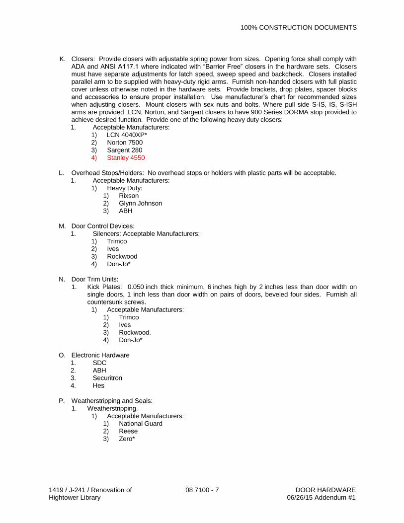
100% CONSTRUCTION DOCUMENTS
1419 / J-241 / Renovation of Hightower Library
08 7100 - 7 DOOR HARDWARE 06/26/15 Addendum #1
K. Closers: Provide closers with adjustable spring power from sizes. Opening force shall comply with
ADA and ANSI A117.1 where indicated with “Barrier Free” closers in the hardware sets. Closers must have separate adjustments for latch speed, sweep speed and backcheck. Closers installed parallel arm to be supplied with heavy-duty rigid arms. Furnish non-handed closers with full plastic cover unless otherwise noted in the hardware sets. Provide brackets, drop plates, spacer blocks and accessories to ensure proper installation. Use manufacturer’s chart for recommended sizes when adjusting closers. Mount closers with sex nuts and bolts. Where pull side S-IS, IS, S-ISH arms are provided LCN, Norton, and Sargent closers to have 900 Series DORMA stop provided to achieve desired function. Provide one of the following heavy duty closers: 1. Acceptable Manufacturers:
1) LCN 4040XP* 2) Norton 7500 3) Sargent 280 4) Stanley 4550
L. Overhead Stops/Holders: No overhead stops or holders with plastic parts will be acceptable.
1. Acceptable Manufacturers: 1) Heavy Duty:
1) Rixson 2) Glynn Johnson 3) ABH
M. Door Control Devices:
1. Silencers: Acceptable Manufacturers: 1) Trimco 2) Ives 3) Rockwood 4) Don-Jo*
N. Door Trim Units:
1. Kick Plates: 0.050 inch thick minimum, 6 inches high by 2 inches less than door width on single doors, 1 inch less than door width on pairs of doors, beveled four sides. Furnish all countersunk screws.
1) Acceptable Manufacturers: 1) Trimco 2) Ives 3) Rockwood. 4) Don-Jo*
O. Electronic Hardware
1. SDC 2. ABH 3. Securitron 4. Hes
P. Weatherstripping and Seals: 1. Weatherstripping.
1) Acceptable Manufacturers: 1) National Guard 2) Reese 3) Zero*

100% CONSTRUCTION DOCUMENTS
1419 / J-241 / Renovation of Hightower Library
08 7100 - 8 DOOR HARDWARE 06/26/15 Addendum #1
2. Gasket: Silicone door gasket, UL-listed.
1) Acceptable Manufacturers: 1) National Guard 2) Reese 3) Zero*
2.03 FINISHES
A. Except as otherwise noted in the hardware sets, provide the following finishes: 1. Exterior Hinges US32D (Stainless Steel) 2. Interior Hinges 652 (Satin Chrome) 3. Continuous Geared Hinges Clear Anodized Aluminum 4. Locks, Latches, Deadlocks US26D (Satin Chrome) 5. Exit Devices US32D (Stainless Steel) 6. Closers and Brackets AL (Powder Coat Aluminum) 7. Push, Pull, Kick and Armor Plates US32D (Stainless Steel) 8. Wall Stops US32D (Stainless Steel) 9. Floor Stops US26D (Satin Chrome) 10. Overhead Stops US26D (Satin Chrome) 11. Thresholds, Weatherstrip, etc. Clear Anodized Aluminum
B. Provide quality of finish, including thickness of plating or coating (if any), composition, hardness and other qualities complying with manufacturer’s standards, but in no case less than specified for the applicable units of hardware by referenced standards.
C. Provide finishes that match those established by BHMA or, if none established, match the
Architect's sample. D. Provide protective lacquer coating on exposed hardware finishes of brass, bronze, and aluminum,
except as otherwise indicated.
E. The designations used in schedules and elsewhere to indicate hardware finishes are those listed in ANSI/BHMA A156.18, including, but not limited to, coordination with the traditional U.S. finishes shown by certain manufacturers for their products, as follows:
PART 3 - EXECUTION 3.01 EXAMINATION
A. Verification of Conditions: Examine areas and conditions under which the work is to be installed,
and notify the Contractor in writing, with a copy to the Owner and the Architect, of any conditions detrimental to the proper and timely completion of the work. Do not proceed with the work until unsatisfactory conditions have been corrected. 1. Beginning of the work shall indicate acceptance of the areas and conditions as satisfactory
by the Installer.
3.02 INSTALLATION
A. Installation shall be in accordance with the manufacturer’s written instructions and recommendations. Wherever cutting and fitting is required to install hardware onto or into surfaces which are later to be painted or finished in some other way, coordinate removal, storage, and installation or application of surface protections with finishing work specified in Division 9 - FINISHES. Do not install surface-mounted items until finishes have been completed on the substrate.

100% CONSTRUCTION DOCUMENTS
1419 / J-241 / Renovation of Hightower Library
08 7100 - 9 DOOR HARDWARE 06/26/15 Addendum #1
B. Mount hardware units at heights indicated in following applicable publications, except as
specifically indicated or required to comply with governing regulations and except as otherwise directed by the Architect. 1. Standard Steel Doors and Frames: DHI RLAHSSDF. 2. Custom Steel Doors and Frames: DHI RLBHCSDF. 3. Flush Wood Doors: WDMA I.S. 1.
C. Set units level, plumb, and true to line and location. Adjust and reinforce the attachment
substrate as necessary for proper installation and operation.
D. Drill and countersink units that are not factory-prepared for anchorage fasteners. Space fasteners and anchors in accordance with industry standards.
E. Set thresholds for exterior doors in full bed of butyl rubber or polyisobutylene mastic sealant
complying with requirements specified in Section 07 92 00 - JOINT SEALERS.
3.03 ADJUSTING
A. Adjusting: Adjust and check each operating item of hardware and each door to ensure proper operation or function of every unit. Replace units which cannot be adjusted to operate freely and smoothly as intended for application made.
B. Final Adjustment: Wherever hardware installation is made more than one month prior to
acceptance or occupancy of a space or area, return to the work during the week prior to acceptance or occupancy and make a final check and adjustment of hardware items in such space or area. Clean operating items as necessary to restore proper function and finish of hardware and doors. Adjust door control devices to compensate for final operation of heating and ventilating equipment. 1. During the final adjustment of hardware, instruct the Owner's personnel in proper use of
special tools and adjustment and maintenance of hardware and hardware finishes.
C. Readjustment: Approximately six months after the date of Substantial Completion, the Installer, accompanied by representatives of the manufacturers of latchsets and locksets and of door control devices, and of other major door hardware suppliers, shall return to the Project to perform the following work: 1. Examine and re-adjust each item of door hardware as necessary to restore function of doors
and hardware to comply with specified requirements. 2. Consult with and instruct the Owner's personnel in recommended additions to the
maintenance procedures. 3. Replace hardware items that have deteriorated or failed due to faulty design, materials, or
installation of hardware units. 4. Prepare a written report of current and predictable problems (of substantial nature) in the
performance of the hardware.
D. Cleaning: Clean adjacent surfaces soiled by hardware installation. 3.04 HARDWARE SCHEDULE

100% CONSTRUCTION DOCUMENTS
1419 / J-241 / Renovation of Hightower Library
08 7100 - 10 DOOR HARDWARE 06/26/15 Addendum #1
HW-AL01
DOOR: 100b ALL HARDWARE TO BE DARK BRONZE FINISH
EACH PAIR TO HAVE: 2 CONT. HINGES FMSLF/SLI**HD (EPT) 393 BOMMER 2 POWER TRANSFERS PT-1000 613 ABH 1 EXIT DEVICE 98NL-OP-SD-EL-RX x CYLINDER ONLY 613 VON DUPRIN 1 EXIT DEVICE 98-EO-SD-RX 613 VON DUPRIN 1 MULLION 4954 X ANGLE PLATE SP313 VON DUPRIN 1 RIM CYLINDER 1E72 613 BEST 3 MORTISE CYLINDERS 1E74 613 BEST 2 LADDER PULLS OPL5141 x 48” x OFFSET x ONE SIDED 630 DON-JO 1 AUTO OPERATOR SEE SECTION 08 7113 1 CLOSER 4040XP-18G 695 LCN 2 CONCEALED OVERHEAD STOPS 100S 613 GJ 1 ADA ACTUATOR SEE SECTION 08 7113 1 PERIMETER SEALS BY DOOR/FRAME MFG. 2 DOOR BOTTOMS BY DOOR/FRAME MFG. 1 THRESHOLD 65B B ZERO 1 POWER SUPPLY PS914-900-2RS VON DUPRIN 2 DOOR POSITION SWITCHES 1078W G SENTROL 1 CARD READER BY SECURITY/ACCESS CONTROL HW-AL02 DOOR: 100a ALL HARDWARE TO BE DARK BRONZE FINISH
EACH PAIR TO HAVE: 2 CONT. HINGES FMSLF/SLI**HD (EPT) 393 BOMMER 2 POWER TRANSFERS PT-1000 613 ABH 1 EXIT DEVICE 98NL-OP-SD-RX x CYLINDER ONLY 613 VON DUPRIN 1 EXIT DEVICE 98-EO-SD-RX 613 VON DUPRIN 1 MULLION 4954 X ANGLE PLATE SP28 VON DUPRIN 1 RIM CYLINDER 1E72 613 BEST 3 MORTISE CYLINDERS 1E74 613 BEST 2 LADDER PULLS OPL5141 x 48” x OFFSET x ONE SIDED 630 DON-JO 2 CLOSERS 4040XP-18G 695 LCN 2 CONCEALED OVERHEAD STOPS 100S 613 GJ 1 PERIMETER SEALS BY DOOR/FRAME MFG. 2 DOOR BOTTOMS BY DOOR/FRAME MFG. 1 THRESHOLD 65B B ZERO 2 DOOR POSITION SWITCHES 1078W G SENTROL

100% CONSTRUCTION DOCUMENTS
1419 / J-241 / Renovation of Hightower Library
08 7100 - 11 DOOR HARDWARE 06/26/15 Addendum #1
HW-AL03
DOOR: 100d ALL HARDWARE TO BE DARK BRONZE FINISH
EACH PAIR TO HAVE: 2 CONT. HINGES FMSLF/SLI**HD 393 BOMMER 2 DUMMY PUSHES 350 613 VONDUPRIN 2 LADDER PULLS OPL5141 x 48” x OFFSET x ONE SIDED 630 DON-JO 1 AUTO OPERATOR SEE SECTION 08 7113 1 CLOSERS 4040XP-18G 695 LCN 2 CONCEALED OVERHEAD STOPS 100S 613 GJ 1 BOLLARD SEE SECTION 08 7113 1 DUAL ADA ACTUATOR SEE SECTION 08 7113 1 ADA JAMB ACTUATOR SEE SECTION 08 7113 HW-AL04
DOOR: 100c ALL HARDWARE TO BE DARK BRONZE FINISH
EACH PAIR TO HAVE: 2 CONT. HINGES FMSLF/SLI**HD 393 BOMMER 2 DUMMY PUSHES 350 613 VONDUPRIN 2 LADDER PULLS OPL5141 x 48” x OFFSET x ONE SIDED 630 DON-JO 2 CLOSERS 4040XP-18G 695 LCN 2 CONCEALED OVERHEAD STOPS 100S 613 GJ HW-AL05
DOOR: 101a ALL HARDWARE TO BE DARK BRONZE FINISH
EACH TO HAVE: 1 CONT. HINGES FMSLF/SLI**HD (EPT) 393 BOMMER 1 POWER TRANSFERS PT-1000 613 ABH 1 EXIT DEVICE 98-EO-SD-RX 613 VON DUPRIN 1 MORTISE CYLINDERS 1E74 613 BEST 1 LADDER PULLS OPL5141 x 48” x OFFSET x ONE SIDED 630 DON-JO 1 CLOSERS 4040XP-18G 695 LCN 1 CONCEALED OVERHEAD STOPS 100S 613 GJ 1 PERIMETER SEALS BY DOOR/FRAME MFG. 1 DOOR BOTTOMS BY DOOR/FRAME MFG. 1 THRESHOLD 65B B ZERO 1 DOOR POSITION SWITCHES 1078W G SENTROL

100% CONSTRUCTION DOCUMENTS
1419 / J-241 / Renovation of Hightower Library
08 7100 - 12 DOOR HARDWARE 06/26/15 Addendum #1
HW-01 DOOR: 101b
EACH TO HAVE:
1 CONTINUOUS HINGE FM**HD x EPT PREP 628 BOMMER 1 POWER TRANSFER PT1000 630 ABH 1 EXIT DEVICE CX98EO 630 VON DUPRIN 1 POWER SUPPLY PS914 VON DUPRIN 1 CLOSER 4040XP-CUSH 689 LCN 1 KICK PLATE J102 .050 8 X 34 630 DJ 1 WEATHER STRIP 328 A ZERO 1 SWEEP 39 A ZERO 1 THRESHOLD 65A A ZERO 1 DOOR POSITION SWITCH 1078W G DORMA HW-02 DOOR: ES1b
EACH TO HAVE:
1 CONTINUOUS HINGE FM**HD x EPT PREP 628 BOMMER 1 POWER TRANSFER PT1000 630 ABH 1 EXIT DEVICE 98NL x EL-RX 630 VON DUPRIN 1 RIM CYLINDER 1E72 626 BEST 1 CLOSER 4040XP-SCUSH 689 LCN 1 KICK PLATE J102 .050 8 X 34 630 DJ 1 WEATHER STRIP 328 A ZERO 1 SWEEP 39 A ZERO 1 THRESHOLD 65A A ZERO 1 POWER SUPPLY PS914-900-2RS VON DUPRIN 1 DOOR POSITION SWITCH 1078W G DORMA 1 CARD READER BY SECURITY/ACCESS CONTROL HW-03 DOOR: ES1ar
EACH TO HAVE:
1 CONTINUOUS HINGE FM**HD x EPT PREP 628 BOMMER 1 POWE TRANSFER PT1000 630 ABH 1 EXIT DEVICE 98NL-F-EL-RX 630 VON DUPRIN 1 RIM CYLINDER 1E72 626 BEST 1 CLOSER 4040XP-SCUSH 689 LCN 1 KICK PLATE J102 .050 8 X 34 630 DJ 1 PERIMETER SEAL 488S BK ZERO 1 POWER SUPPLY PS914-900-2RS VON DUPRIN 1 DOOR POSITION SWITCH 1078W G DORMA 1 CARD READER BY SECURITY/ACCESS CONTROL

100% CONSTRUCTION DOCUMENTS
1419 / J-241 / Renovation of Hightower Library
08 7100 - 13 DOOR HARDWARE 06/26/15 Addendum #1
HW-04 DOOR: 103
EACH TO HAVE: 3 HINGES BB5000-450 652 BOMMER 1 PASSAGE SET 93KON 626 BEST 1 ELECTRIC STRIKE 1006 CS 630 HES 1 ADA AUTO OPERATOR SEE SECTION 08 7113 1 ACTUATOR SEE SECTION 08 7113 1 ACTUATOR SEE SECTION 08 7113 1 KICK PLATE J102 .050 8 X 34 630 DJ 1 WALL STOP 1407 630 DJ 3 SILENCERS 1608 G DJ HW-05 DOOR: ES2ar
EACH TO HAVE:
3 HINGES BB5000-450 652 BOMMER 1 POWER TRANSFER PT1000 630 ABH 1 EXIT DEVICE CX99L-F 630 VON DUPRIN 1 POWER SUUPLY PS914 VON DUPRIN 1 RIM CYLINDER 1E72 626 BEST 1 CLOSER 4040XP- REG ARM 689 LCN 1 KICK PLATE J102 .050 8 X 34 630 DJ 1 WALL STOP 1407 630 DJ 1 PERIMETER SEAL 488S BK ZERO 1 DOOR POSITION SWITCH 1078W G DORMA HW-06 FIRE SHUTTERS/GRILLS: 229, 231, 231r, 232, 233, 234, ALL HARDWARE BY DOOR/FRAME MFG. HW-07 DOORS: 104, 121, EACH PAIR TO HAVE: 6 HINGES BB5000-450 652 BOM 2 FLUSHBOLTS 1555 626 DJ 1 DUSTPROOF STRIKE 1570 626 DJ 1 CLASSROOM LOCK 93K7R 626 BEST 2 OVERHEAD STOPS 90S 630 GJ 1 ASTRAGAL FMEA ANEMO 2 SILENCERS 1608 G DJ

100% CONSTRUCTION DOCUMENTS
1419 / J-241 / Renovation of Hightower Library
08 7100 - 14 DOOR HARDWARE 06/26/15 Addendum #1
HW-08 DOORS: 115, 118a, 119, 120, 124,
EACH TO HAVE:
3 HINGES BB5000-450 652 BOMMER 1 ENTRANCE LOCK 93K7AB 626 BEST 1 WALL STOP 1407 630 DJ 3 SILENCERS 1608 (OMIT @ ALUM. FRAMES) G DJ HW-09 DOORS: 118b
EACH TO HAVE:
3 HINGES BB5000-450 652 BOMMER 1 ENTRANCE LOCK 93K7AB 626 BEST 1 CLOSER 4040XP-S-CUSH 30 / 61 689 LCN HW-10 DOORS: 102
EACH TO HAVE:
3 HINGES BB5000-450 652 BOMMER 1 CLASSROOM LOCK 93K7R 626 BEST 1 FLOOR STOP 1450 626 DJ 3 SILENCERS 1608 G DJ HW-11 DOORS: 105, 116, 206, 207, 208, 209, 210, 211, 212, 213
EACH TO HAVE:
3 HINGES BB5000-450 652 BOMMER 1 CLASSROOM LOCK 93K7R 626 BEST 1 CONCEALED OVERHEAD STOP 104S 630 GJ 3 SILENCERS 1608 (OMIT @ ALUM. FRAMES) G DJ

100% CONSTRUCTION DOCUMENTS
1419 / J-241 / Renovation of Hightower Library
08 7100 - 15 DOOR HARDWARE 06/26/15 Addendum #1
HW-12 DOORS: 117, 201, 202, 203, 204, 205, 220, 221, 222, 223, 224, 225, 228,
EACH TO HAVE:
3 HINGES BB5000-450 652 BOMMER 1 CLASSROOM LOCK 93K7R (93K7AB @ 220) 626 BEST 1 WALL STOP 1407 (482 626 @ 210) 630 DJ 3 SILENCERS 1608 (OMIT @ ALUM. FRAMES) G DJ HW-13 DOORS: 106, 216r
EACH TO HAVE:
3 HINGES BB5000-450-N 652 BOMMER 1 STOREROOM LOCK 93K7D x TACTILE 626 BEST 1 CLOSER 4040XP-S-CUSH 689 LCN 1 SOUND SEAL 485A A ZERO 1 AUTO DOOR BOTTOM 361AA AA ZERO HW-14 DOORS: 217
EACH TO HAVE:
3 HINGES BB5000-450-N 652 BOMMER 1 STOREROOM LOCK 93K7D x TACTILE 626 BEST 1 CLOSER 4040XP-EDA 689 LCN 1 WALL STOP 1407 630 DJ 1 PERIMETER SEAL 488S BK ZERO HW-15 DOORS: 113,
EACH TO HAVE:
3 HINGES BB5000-450 652 BOMMER 1 STOREROOM LOCK 93K7D 626 BEST 1 CLOSER 4040XP-CUSH 689 STANLEY 1 KICK PLATE J102 .050 8 X 34 630 DJ 3 SILENCERS 1608 G DJ

100% CONSTRUCTION DOCUMENTS
1419 / J-241 / Renovation of Hightower Library
08 7100 - 16 DOOR HARDWARE 06/26/15 Addendum #1
HW-16 DOORS: 109, 218
EACH TO HAVE:
3 HINGES BB5000-450 652 BOMMER 1 STOREROOM LOCK 93K7D 626 BEST 1 CLOSER 4040XP-EDA(REG ARM 218) 689 LCN 1 KICK PLATE J102 .050 8 X 34 630 DJ 1 WALL STOP 1407 630 DJ 3 SILENCERS 1608 G DJ HW-17 DOORS: 114,
EACH TO HAVE:
3 HINGES BB5000-450 652 BOMMER 1 EXIT DEVICE 98L-BE 630 VD 1 CLOSER 4040XP- REG ARM 689 LCN 1 WALL STOP 1407 630 DJ HW-18 DOOR: 122
EACH TO HAVE:
3 HINGES BB5000-450 652 BOMMER 1 PRIVACY LOCK 45H0L VIN INDICATOR 626 BEST 1 CLOSER 4040XP-REG ARM 689 LCN 1 KICK PLATE J102 .050 8 X 34 630 DJ 1 WALL STOP 1407 630 DJ 1 PERIMETER SEAL 488S BK ZERO HW-19 DOORS: 107, 108, 214, 215 EACH TO HAVE:
3 HEAVY WEIGHT HINGES BB5004-450 652 BOMMER 1 PUSH PLATE 78 630 DJ 1 PULL PLATE 7816 630 DJ 1 CLOSER 4040XP-EDA 689 LCN 1 KICK PLATE J102 .050 8 X 34 630 DJ 1 MOP PLATE J102 .050 6 X 35 630 DJ 1 WALL STOP 1407 630 DJ 1 PERIMETER SEAL 488S BK ZERO

100% CONSTRUCTION DOCUMENTS
1419 / J-241 / Renovation of Hightower Library
08 7100 - 17 DOOR HARDWARE 06/26/15 Addendum #1
HW-21 1 KEY CABINET 201-8120-03 MMF
END OF SECTION 087100
100% CONSTRUCTION DOCUMENTS
1419 / J-241 / Renovation of Hightower Library
08 7113 - 1 AUTOMATIC OPERATOR 04/29/15 06/26/15 Addendum #1
SECTION 08 71 13
AUTOMATIC OPERATORS PART 1 - GENERAL 1.01 RELATED DOCUMENTS
A. Drawings and general provisions of the Contract, including General Conditions,
Division 01 - GENERAL REQUIREMENTS, and other applicable specification sections in the Project Manual apply to the work specified in this Section.
1.02 SUMMARY
A. Scope: Provide labor, material, equipment, related services, and supervision required, including,
but not limited to, manufacturing, fabrication, erection, and installation for automatic entrances as required for the complete performance of the work and as shown on the Drawings and as herein specified.
B. Section Includes: The work specified in this Section includes, but shall not be limited to, the
following: 1. Swinging, power-operated automatic operators.
1.03 REFERENCES
A. ANSI/BHMA A156.19, "Power Assist and Low Energy Power Operated Doors" (copyrighted by
BHMA, ANSI approved). B. NFPA 70, "National Electrical Code" (copyrighted by NFPA, ANSI approved) - hereinafter referred
to as NEC.
1.04 Performance Requirements: Provide automatic operators that comply with performance characteristics specified as demonstrated by testing the manufacturer's corresponding stock assemblies according to test methods indicated.
A. Opening Force: Comply with the following maximum opening force requirements for locations indicated: 1. Exterior Doors: 15 lbf. 2. Interior Doors: 5 lbf.
B. Opening Force for Low Energy Power-Operated Doors: Provide operators that require no more than 15 lbf to stop door movement.
C. Operator: Provide operators that shall open and close doors and maintain them in fully closed position when subjected to the design wind pressures for the Project.
1.05 SUBMITTALS
A. General: See Section 013000 - SUBMITTAL PROCEDURES.
B. Product Data: Submit product data showing material proposed. Submit sufficient information to
determine compliance with the Drawings and Specifications. Product data shall include, but shall not be limited to, manufacturer's standard details and fabrication methods; data on operators, hardware, and accessories; roughing-in diagrams; parts lists; and data on finishes.
100% CONSTRUCTION DOCUMENTS
1419 / J-241 / Renovation of Hightower Library
08 7113 - 2 AUTOMATIC OPERATOR 04/29/15 06/26/15 Addendum #1
C. Shop Drawings: Submit shop drawings for each product and accessory required.
D. Wiring Diagrams: Submit wiring diagrams detailing wiring for power operator, signal, and
control systems differentiating clearly between manufacturer-installed wiring and field-installed wiring. Coordinate with Division 26 - ELECTRICAL.
E. Operation and Maintenance Data: Submit operation and maintenance data for automatic
operators to include in operation and maintenance manuals specified in Division 01 - GENERAL REQUIREMENTS. Include manufacturer's maintenance and service data for door operators and control system, including, but not limited to, the name, address, and telephone number of the nearest authorized service representative. Include manufacturer’s recommendations for maintenance and cleaning of exterior surfaces.
1.06 QUALITY ASSURANCE
A. Qualifications:
1. Manufacturer Qualifications: Manufacturer shall be a firm engaged in the manufacture of automatic entrances, and whose products have been in satisfactory use in similar service for a minimum of five years.
a. Manufacturer shall be AAADM certified. 2. Installer Qualifications: Installer shall be a firm that shall have a minimum of five years of
successful installation experience with projects utilizing automatic operators similar in type and scope to that required for this Project, and shall be approved by the manufacturer.
B. Regulatory Requirements: Comply with applicable requirements of the laws, codes, ordinances,
and regulations of Federal, State, and local authorities having jurisdiction. Obtain necessary approvals from such authorities.
C. Standards:
1. BHMA Standards: Provide low energy automatic operator units that comply with applicable requirements of ANSI/BHMA A156.19.
2. UL Standards: Provide powered door operators that comply with UL 325. 3. Electrical Components, Devices, and Accessories: Electrical components, devices,
and accessories shall be listed and labeled as defined in NEC, Article 100, by an inspecting and testing agency acceptable to authorities having jurisdiction, and marked for intended use.
D. Single Source Responsibility: Obtain automatic entrances from a single source with resources to
produce products of consistent quality in appearance and physical properties without delaying the work.
E. Coordination:
1. Coordinate hardware with doors, frames, and related work to ensure proper size, thickness, hand, function, and finish. Coordinate automatic operators with hardware required for the rest of the Project.
2. Refer to Hardware Sets in Section 087100 – DOOR HARDWARE for listing of doors to receive automatic swing door operators and accessories provided in this section.
1.07 DELIVERY, STORAGE, AND HANDLING
A. Deliver materials to the Project site in supplier’s or manufacturer’s original wrappings and
containers, labeled with supplier’s or manufacturer’s name, material or product brand name, and lot number, if any.

100% CONSTRUCTION DOCUMENTS
1419 / J-241 / Renovation of Hightower Library
08 7113 - 3 AUTOMATIC OPERATOR 04/29/15 06/26/15 Addendum #1
B. Store materials in their original, undamaged packages and containers, inside a well-ventilated area
protected from weather, moisture, soiling, extreme temperatures, and humidity. 1.08 WARRANTY
A. General: See Section 017700 - CLOSEOUT PROCEDURES.
B. Warranty: Submit a written warranty executed by the manufacturer, the Installer, and the
Contractor, agreeing to repair or replace automatic operators that fails in materials or workmanship within the specified warranty period. 1. Warranty Period: Warranty period shall be five years after the date of Substantial
Completion.
C. Additional Owner Rights: The warranty shall not deprive the Owner of other rights the Owner may have under other provisions of the Contract Documents and shall be in addition to and run concurrent with other warranties made by the Contractor under requirements of the Contract Documents.
PART 2 - PRODUCTS 2.01 MATERIALS
A. Fasteners: Provide aluminum, non-magnetic stainless steel, or other non-corrosive metal
fasteners compatible with aluminum components, hardware, anchors, and other items being fastened. 1. Reinforcement: Where fasteners screw-anchor into aluminum members less than
0.125 inch thick, reinforce the interior with aluminum or non-magnetic stainless steel to receive screw threads, or provide standard non-corrosive pressed-in, splined grommet nuts.
2. Exposed Fasteners: Do not use exposed fasteners except for application of hardware. For application of hardware, use Phillips flat head machine screws that match the finish of member or hardware being fastened.
2.02 LOW ENERGY DOOR OPERATORS
A. General: Provide operators of the size recommended by the manufacturer for door size, weight,
and movement, for condition of exposure, and for long-term, maintenance-free operation under normal traffic load for the type of occupancy indicated. 1. Type: Power-operated. 2. Connections: Provide connections for power and control wiring. 3. Adjustment Features: Operators shall be fully adjustable:
a. Adjustable speed, including, but not limited to, opening, closing, and latch check. b. Adjustable time delay for length of time door remains open. c. Automatic door re-open if stopped while closing.
4. Microprocessor Control: System that automatically defines and sets opening and closing parameters.
5. On/Off Feature: Provide on/off/hold-open switch to control electric power to operator. B. Electromechanical Operators: Provide self-contained, surface mounted, overhead units with
power opening and closing mechanism indicated below. Provide closing speed controlled by gear train and dynamic braking action of electric motor, with manual operation and spring closing when power is off. Provide operator action as indicated.
100% CONSTRUCTION DOCUMENTS
1419 / J-241 / Renovation of Hightower Library
08 7113 - 4 AUTOMATIC OPERATOR 04/29/15 06/26/15 Addendum #1
1. Closing Mechanism for Swing Doors: Power-assisted spring closing for overcoming
wind and static pressures. 2. Mounting: Surface Mounted Push Side or Surface Mounted Pull Side. 3. Manual Operation for Swing Doors: Operation shall require less than 15 lbf to release a
latch, 30 lbf to set door in motion, and 15 lbf to fully open door when power is off, in accordance with ANSI/BHMA A156.19.
4. Onboard Power Supply: Power supply for access control devices – 1.5A @ 24VDC. 5. Latching Action Force: Power boost during latching cycle to overcome resistance for
door seals or locking devices. 6. Obstacle Detection: The door closes if obstacle is detected during the opening cycle
and reopens if an obstacle is detected during the closing cycle. 7. Self-diagnosing Status Indicator: LED display error code messages. 8. Push & Go: Triggered by manually opening the door four degrees from the closed
position. 9. Pair Operation: Operators on pairs of doors to open both leaves simultaneously. 10. Basis of Design: ED100/ED250 by DORMA USA, Inc.
2.03 ACTIVATION AND SAFETY DEVICES
A. Wall Mounted Actuators: Where Wall Mounted Actuators are required provide 4½” x 4½” switches that meet the following requirements: 1. Material: Stainless steel. 2. Message: International symbol of accessibility and “Push to Open.” 3. Manufacturer: WIKK, DORMA.
B. Vestibule Mounted Actuators: Where Wall Mounted Actuators are required provide 4½” x 4½” switches that meet the following requirements: 1. Material: Stainless steel. 2. Message: International symbol of accessibility and “Push to Open.” 3. Manufacturer: WIKK
C. Jamb Mounted Actuators: Where Jamb Mounted Actuators are required provide narrow
switches that fit on aluminum frame mullion that meet the following requirements: 1. Material: Stainless steel. 2. Message: International symbol of accessibility and “Push to Open.” 3. Manufacturer: WIKK, DORMA
2.04 COVER
A. Provide continuous single cover on pairs of operators.
PART 3 - EXECUTION 3.01 EXAMINATION
A. Verification of Conditions: Examine areas and conditions under which the work is to be installed,
and notify the Contractor in writing, with a copy to the Owner and the Architect, of any conditions detrimental to the proper and timely completion of the work. Do not proceed with the work until unsatisfactory conditions have been corrected. 1. Beginning of the work shall indicate acceptance of the areas and conditions as satisfactory
by the Installer.

100% CONSTRUCTION DOCUMENTS
1419 / J-241 / Renovation of Hightower Library
08 7113 - 5 AUTOMATIC OPERATOR 04/29/15 06/26/15 Addendum #1
3.02 PREPARATION
A. Templates and Diagrams: Furnish templates, diagrams, and other data to fabricators and
installers of related work, as necessary, for coordination of the automatic entrance installation
3.03 INSTALLATION
A. Install complete door operator system, activation devices, and safety devices in accordance with manufacturer's written instructions. Do not install damaged components.
3.04 ADJUSTING AND CLEANING
A. Adjust door operators, controls, and hardware for smooth and safe operation and for weathertight closure. After repeated operation of completed installation, equivalent to three days use by normal traffic (100 to 300 cycles), readjust door operators and controls. Lubricate hardware, operating equipment, and other moving parts.
HW-AL01
DOOR: 100B
EACH PAIR TO HAVE: 1 AUTO OPERATOR ED100 FLUSH CEILING MOUNT 695 DAH 1 ADA ACTUATOR 4 X 4 – 3 X N4NF4R-5 630 WIKK HW-AL03
DOOR: 100D
EACH PAIR TO HAVE: 1 AUTO OPERATOR ED100 FLUSH CEILING MOUNT 695 DAH 1 BOLLARD BPR SM AIMSDB PREP FOR D. ACTUATOR DB WIKK 1 DUAL ADA ACTUATOR AA-3 AL X AA-3 AR 630 WIKK
1 ADA JAMB ACTUATOR AA-3 630 WIKK
HW-04 DOOR: 105 103
EACH TO HAVE:

100% CONSTRUCTION DOCUMENTS
1419 / J-241 / Renovation of Hightower Library
08 7113 - 6 AUTOMATIC OPERATOR 04/29/15 06/26/15 Addendum #1
1 ADA AUTO OPERATOR ED100 PULL 689 DAH 1 ACTUATOR 4R-5 INSIDE ROOM 630 WIKK 1 ACTUATOR AA-3 OUTSIDE JAMB MT. 630 WIKK
END OF SECTION

1419 / J-241 / Renovation of Hightower Library
09 8400 - 1 ACOUSTIC ROOM COMPONENTS
06/26/15 Addendum #1
SECTION 09 8400
ACOUSTIC COMPONENTS
PART 1 GENERAL
1.01 SECTION INCLUDES
A. Fabric-covered mineral fiber core panels and mounting accessories.
B. Felt panels.
1.02 RELATED REQUIREMENTS
A. Section 01 6116 - Volatile Organic Compound (VOC) Content Restrictions.
B. Section 09 2116 – Gypsum Board Assemblies: reveal moldings.
1.03 REFERENCE STANDARDS
A. ASTM C423 - Standard Test Method for Sound Absorption and Sound Absorption Coefficients by the Reverberation Room Method; 2009a.
B. ASTM E84 - Standard Test Method for Surface Burning Characteristics of Building Materials; 2014.
C. ASTM E795 - Standard Practices for Mounting Test Specimens During Sound Absorption Tests; 2005 (Reapproved 2012).
1.04 SUBMITTALS
A. See Section 01 3000 - Administrative Requirements, for submittal procedures.
B. Product Data: Manufacturer's printed data sheets for products specified.
C. Shop Drawings: Fabrication and installation details, panel layout, and fabric orientation.
D. Verification Samples: Fabricated samples of each type of panel specified; 12 x 12 inch (305 x 305 mm), showing construction, edge details, and fabric covering.
1.05 QUALITY ASSURANCE
A. Manufacturer Qualifications: Company with not less than 5 years of experience in manufacturing acoustical products similar to those specified.
1.06 DELIVERY, STORAGE, AND HANDLING
A. Protect acoustical panels from moisture during shipment, storage, and handling. Deliver in factory-wrapped bundles; do not open bundles until panels are needed for installation.
B. Store panels flat, in dry, well-ventilated space; do not stand panels on end.
C. Protect panel edges from damage.
PART 2 PRODUCTS
2.01 MANUFACTURERS
A. Fabric-Covered Acoustical Panels:
1. Armstrong World Industries, Inc; _____: www.armstrong.com.
2. CertainTeed Corporation; _____: www.certainteed.com.
3. Essi Acoustical Products Company; _____: www.essiacoustical.com.
4. Kinetics Noise Control. www.kineticsnoise.com.
5. Fabric Mate. www.fabricmate.com.
6. Substitutions: See Section 01 6000 - Product Requirements.
2.02 ACOUSTICAL PANELS
A. Panels: Prefinished, factory assembled fabric-covered panels.
B. Mineral Fiber Core or Fiberglass Panels:
1. Density: 18-20 lb/cu ft (288-320 kg/cu m).
2. Noise Reduction Coefficient (NRC): 0.50-0.60 when tested in accordance with ASTM C423 for Type A mounting, per ASTM E795.

100% CONSTRUCTION DOCUMENTS
1419 / J-241 / Renovation of Hightower Library
09 8400 - 2 ACOUSTIC ROOM COMPONENTS
04/29/1506/26/15 Addendum #1
3. Panel Width: As detailed.
4. Panel Height: As detailed.
5. Panel Thickness: As required to meet required acoustical performance.
6. Edges: Perimeter edges reinforced by an aluminum frame or a galvanized steel frame.
7. Corners: Square.
8. Mounting: Spline-mounted by kerfed and rabbeted long edges.
C. Fabric Covering: Seamless fabric facing material, for stretched covering of core material.
1. Color: U-1, As scheduled on Sheet AI001.
2.03 FELT PANELS
A. Panels: Basis of Design - Matrix Hanging Panel, by Filzfelt.
1. Applications: Study room and Conference room walls, and as indicated in the drawings.
2. Thickness: 3/16 inch (5 mm)
3. Color: 175 – Graphit
4. Panel Size: As detailed in drawings.
5. Flammability: ASTM E 84 Class A
2.04 FABRICATION
A. Fabric Wrapped, General: Fabricate panels to sizes and configurations indicated, with fabric facing installed without sagging, wrinkles, blisters, or visible seams.
1. Where radiused or mitered corners are indicated, install fabric to avoid seams or gathering of material.
2.05 ACCESSORIES
A. Spline-Mounting Accessories: Manufacturer's standard concealed connecting splines of extruded aluminum designed for screw attachment to walls, with coordinating moldings and trim for interior and exterior corners and miscellaneous conditions.
1. Color of Exposed Trim: As selected from manufacturer's standards.
B. Back-Mounting Accessories: Manufacturer's standard accessories for concealed support, designed to allow panel removal, and as follows:
PART 3 EXECUTION
3.01 EXAMINATION
A. Examine substrates for conditions detrimental to installation of acoustical panels. Proceed with installation only after unsatisfactory conditions have been corrected.
3.02 INSTALLATION
A. Install acoustical panels in locations indicated, following installation recommendations of panel manufacturer. Align panels accurately, with edges plumb and top edges level. Scribe to fit accurately at adjoining work and penetrations.
B. Refer to section 09 2116 for reveal moldings around perimeter of felt panels. Cut panel to review molding.
C. Felt panels to be direct glued to wall, per manufacturer’s instructions.
3.03 CLEANING
A. Clean fabric facing upon completion of installation from dust and other foreign materials, following manufacturer's instructions.
B. Remove surplus materials, trimmed portions of panels, and debris resulting from installation.
3.04 PROTECTION
A. Provide protection of installed acoustical panels until completion of the work.
B. Replace panels that cannot be cleaned and repaired to satisfaction of the Houser Walker Architecture.
END OF SECTION

1419 / J-241 / Renovation of Hightower Library
10 1400 - 1 SIGNAGE
SECTION 10 1400
SIGNAGE
PART 1 GENERAL
1.01 SECTION INCLUDES
A. Salvage and reuse of existing signs.
B. Room and door signs.
C. Interior directional and informational signs.
D. Emergency evacuation maps.
1.02 REFERENCE STANDARDS
A. 36 CFR 1191 - Americans with Disabilities Act (ADA) Accessibility Guidelines for Buildings and Facilities; Architectural Barriers Act (ABA) Accessibility Guidelines; current edition.
B. ADA Standards - Americans with Disabilities Act (ADA) Standards for Accessible Design; 2010.
C. ICC A117.1 - Accessible and Usable Buildings and Facilities; International Code Council; 2009 (ANSI).
1.03 SUBMITTALS
A. See Section 01 3000 - Administrative Requirements, for submittal procedures.
B. Product Data: Manufacturer's printed product literature for each type of sign, indicating sign styles, font, foreground and background colors, locations, overall dimensions of each sign.
C. Signage Schedule: Provide information sufficient to completely define each sign for fabrication, including room number, room name, other text to be applied, sign and letter sizes, fonts, and colors.
1. When room numbers to appear on signs differ from those on the drawings, include the drawing room number on schedule.
2. When content of signs is indicated to be determined later, request such information from Owner through Houser Walker Architecture at least 2 months prior to start of fabrication; upon request, submit preliminary schedule.
3. Submit for approval by Owner through Houser Walker Architecture prior to fabrication.
D. Selection Samples: Where colors are not specified, submit two sets of color selection charts or chips.
1.04 QUALITY ASSURANCE
A. Manufacturer Qualifications: Company specializing in manufacturing the products specified in this section with minimum three years of documented experience.
1.05 DELIVERY, STORAGE, AND HANDLING
A. Package signs as required to prevent damage before installation.
B. Package room and door signs in sequential order of installation, labeled by floor or building.
C. Store tape adhesive at normal room temperature.
1.06 FIELD CONDITIONS
A. Do not install tape adhesive when ambient temperature is lower than recommended by manufacturer.
B. Maintain this minimum temperature during and after installation of signs.
PART 2 PRODUCTS
2.01 SIGNAGE APPLICATIONS
A. Existing Signs: The existing signs at the existing rooms indicated to remain as the same room, are to be salvaged and reinstalled over new wall finish. New location is indicated in the drawings.
100% CONSTRUCTION DOCUMENTS
1419 / J-241 / Renovation of Hightower Library
10 1400 - 2 SIGNAGE 04/29/15
B. Refer to the Gordon College Sign Guideline Manual (Oct. 2008) for sign types and requirements. http://www.gordonstate.edu/advancement/graphic-standards-manual-logo-downloads
C. Accessibility Compliance: Signs are required to comply with ADA Standards and ICC A117.1 and applicable building codes, unless otherwise indicated; in the event of conflicting requirements, comply with the most comprehensive and specific requirements.
D. Room and Door Signs: Provide a sign for every doorway, whether it has a door or not, not including corridors, lobbies, and similar open areas.
1. Sign Type: Flat signs with engraved panel media as specified.
2. Provide "tactile" signage, with letters raised minimum 1/32 inch (0.8 mm) and Grade II braille.
3. Character Height: 1 inch (25 mm).
4. Sign Dimensions: as indicated in attached Campus Standards.
5. Office Doors: Identify with room numbers to be determined later, not the numbers shown on the drawings; in addition, provide "window" section for replaceable occupant name.
6. Classroom, Conference and Meeting Rooms: Identify with room numbers to be determined later, not the numbers shown on the drawings.
7. Suite Rooms: Identify with room department name and numbers to be determined later.
8. Utility Rooms: Identify with room names and numbers to be determined later, not those shown on the drawings.
9. Rest Rooms: Identify with pictograms, the names "MEN" and "WOMEN", symbols and braille.
E. Interior Directional and Informational Signs:
1. Vinyl lettering
a. Sizes: As indicated on the drawings.
b. Character Case: As indicated on the drawings.
c. Character Font: Avenir 65
d. Character Color: As indicated on the drawings.
e. Wording of signs is scheduled on the drawings.
f. Fabrication: EPS files of anamorphic lettering to be provided by Architect.
F. Elevator Signs: Existing to be salvaged and reinstalled.
G. Other Dimensional Letter Signs: Base-mounted at circulation desk.
1. Interior: Allow for total of 50 letters, 6 inches (150 mm) high, plastic.
2.02 SIGN TYPES
A. Flat Signs: Signage media without frame.
1. Edges: Square.
2. Corners: Square.
3. Wall Mounting of One-Sided Signs: Tape adhesive.
B. Color and Font: Unless otherwise indicated:
1. Character Font: As indicated in Campus Standards.
2. Character Case: Upper and lower case (title case).
3. Background Color: As indicated in Campus Standards.
4. Character Color: Contrasting color.
2.03 TACTILE SIGNAGE MEDIA
A. Engraved Panels: Laminated colored plastic; engraved through face to expose core as background color:
1. Total Thickness: 1/16 inch (1.6 mm).
2.04 DIMENSIONAL LETTERS
A. Plastic Letters:
1. Material: Acrylic plastic sheet, flat.
2. Color: As selected.
100% CONSTRUCTION DOCUMENTS
1419 / J-241 / Renovation of Hightower Library
10 1400 - 3 SIGNAGE 04/29/15
3. Thickness: 1/8 inch.
4. Mounting: Tape adhesive.
5. Character Font: Avenir 65.
PART 3 EXECUTION
3.01 EXAMINATION
A. Verify that substrate surfaces are ready to receive work.
3.02 INSTALLATION
A. Install in accordance with manufacturer's instructions.
B. Install neatly, with horizontal edges level.
C. Provide back panel for signs to be installed on glazing panels.
D. Locate signs where indicated:
1. Room and Door Signs: Locate on wall at latch side of door with centerline of sign at 60 inches (1525 mm) above finished floor.
2. If no location is indicated obtain Owner's instructions.
E. Protect from damage until Substantial Completion; repair or replace damage items.
3.03 ATTACHMENTS
A. Gordon College Sign Guideline Manual, October 2008.
END OF SECTION

Campus Sign Guidelines �
� Gordon College Campus Sign Guidelines �
table of contents
introduction . . . . . . . . . . . . . . . 5
design principals . . . . . . . . . . . . 6
graphic standards . . . . . . . . . . . 8
design guidelines . exterior . . . . . 13
design guidelines . interior . . . . . 31

� Gordon College Campus Sign Guidelines �
Gordon College joined the University System of Georgia in 1972 as an associate level institution with a distinctive legacy of excellence in scholarship and service. From its founding in 1852, Gordon has grown and changed, not only in response to, but also in anticipation of, the education needs of its community. Gordon’s scope of influence now extends beyond the surrounding areas to include the rapidly growing suburban areas south of Atlanta, east of Columbus, and north of Macon. A community in flux, this area of Georgia is rich in diversity and reflects extremes in economic and population growth which demand a mission that includes a focused two-year professional offerings, the traditional pre baccalaureate curricula, and baccalaureate offerings targeting the needs of the area.
In order to better serve the needs of the surrounding community and create a welcoming and inviting campus environment for the community and students alike, Gordon College in partnership with Sasaki Associates, Inc. developed a campus master plan that was completed in early 2008. The masterplan recommended a new, comprehensive sign and wayfinding program for the campus.
Since early spring 2008, Sasaki has been collaborating with a committee created to spearhead the design and development of a new sign program.Representatives from Student Life, Marketing and Communications, Facilities and Maintenance, Academics and Administration, Student Representatives and members of the community were welcomed, and attended the conceptual and developmental stages of programming and design. The local community and College alumni were also welcomed.
It was agreed that a well planned and designed system of signs would contribute to the overall aesthetic appearance of the Gordon College campus. The primary function would be to index primary campus destinations, aid in navigation, and deliver communications for planned events on campus, and in downtown Barnesville.
While the sign program will be focused for prospective students, event attendees, visiting athletic teams, vendors and delivery drivers, it must also be an asset to the audience that interacts with the campus in an everyday capacity. New and returning students, faculty and staff, alumni, and participants in the Gordon College community outreach programs: Gordon Youth Science and Technology Center (GYSTC), and Community Education, will also use this system to navigate the campus.
Specific, tangible goals for this sign new system include:
> Direct visitors, parents, staff and prospective students to campus from the highway with a clear trailblazing system that confirms the paths to campus.
> Create memorable gateways at major entrances to campus.
> Provide a clear way to navigate the environment, while presenting a memorable identity for its wide range of audience, including students, guests, visitors, and community.
> Create a visual hierarchy of sign types.
> Present information in a uniform manner, with the ability to change information if and when desired.
> Establish a visible College Identity along College Drive, to reinforce the campus’ presence along public roads and within the community.
> Reflect a friendly, open environment to students, visitors, and the community.
> Reinforcing the Gordon College brand consistently through the use of the College identity on signs and kiosks.
The Sign Committee determined that the sign system should reflect a College that is:
> Forward thinking
> Technology Minded
> Linked to an historic past
> Focused on students and parents
> Representing a college for all people
introduction

� Gordon College Campus Sign Guidelines
design principalsguid ing pr inc ipa l s
The sign system was developed with the following principals in mind:
> To build upon and supplement the Gordon College Identity established by the Office of Advancement.
> To reinforce the image and character of Gordon College.
> To reinforce the College’s identity at campus entrances, along campus edges and in the approach to campus.
> Provide consistency of information: online, in print, on campus, and beyond.
> Provide a foundation with the flexibility to be implemented as the campus continues its growth.
> Provide a clear organized medium to ease wayfinding for both vehicular and pedestrian traffic.
des ign ph i losophy
The sign system was designed within a criteria set forth by the committee to portray Gordon College’s forward looking initiatives while considering connections to the historic past and alumni. Each sign element has been designed to coordinate together, so that the components will function together as a uniform system, for both the exterior campus and inside campus buildings.
As designed, the sign system embodies the following:
> A classic feel with a modern flare
> Maintains a clean presentation while not being overly ornamental
> Presents information with a strong typographic treatment
> Complements the Gordon College Identity Manual
> Envigorate the campus landscape with an infusion of color
In a future phase, a full “bid package”, containing drawings and specifications, will refer to this campus sign guidelines document - and put forth requirements for final sign messaging, shop drawings, sample submittals, and performance specifications.
admin i s t ra t ion and procedure
This sign guideline manual is to be used to guide College administration and maintenance staff. It does not include engineering requirements or final messaging. While it does set forth recommendations in messaging, it is only a snapshot of the current campus environment. As the Master plan for the campus is implemented, with its recommended programming and changes, the sign program can be updated and augmented to address the needs of the campus.

� Gordon College Campus Sign Guidelines �
graphic standards

� Gordon College Campus Sign Guidelines
college identity
l ogoUse of the Gordon College Logo in the sign and wayfinding program follows standards outlined in the Gordon College Graphic Identity Manual as published by the Office of Advancement. The Gordon College “BIG G” logo should appear on signs only as specifically designated in this manual. The Gordon College logo may be obtained by contacting the Office of Institutional Advancement.
l ogo typeUse of the Gordon College logotype in the sign and wayfinding program follows standards outlined in the Gordon College Graphic Identity Manual as published by the Office of Advancement. The Gordon College logotype should appear on signs only as specifically designated in this manual. As all use of the college logotype is above 13 pt. only the Futura Light version should be used. The Gordon College logotype may be obtained by contacting the Office of Institutional Advancement.
sea lThe Gordon College seal shall be reserved for official college use only and shall not appear on items that have not been reviewed by Campus Administration or the Office of Institutional Advancement.
l ogo and logo type do’s and do no t ’s> do not stretch logo or logotype
> do not skew the logo or logotype
> do not use any font other than the approved fonts
> do use a white logo on colored field
> do obtain the official logo or logotype by contacting the Office of Institutional Advancement
> do review any use of the logo or logotype with the Office of Institutional Advancement prior to implementation

� Gordon College Campus Sign Guidelines �
typography overview
t ypographyThe Campus Sign program utilizes 2 type families, ITC Berkeley an early twentieth century Venetian old style serif font designed by Frederic Goudy; and Helvetica Neue, a late twentieth century contemporary sans serif font designed by the Linotype Corporation.
These two typefaces are used in conjunction with each other to provide balance, a clean look and feel for the sign program. Characters from each font are represented here for visual reference only.
Berkeley and Helvetica Neue are available in Windows, Macintosh and Open Type format by contacting: Adobe Systems Incorporated 345 Park Ave. San Jose, CA 95110 1-800-585-0774 or online at www.adobe.com
t ypography do’s and do no t ’s> do not apply “effects” to letters, such as drop shadows
> when using italic text, use the actual italic font, do not apply an italic style or distort the roman font
> when using the condensed typeface, use the actual condensed font, do not “squeeze” the roman (more open) letterforms
berke ley o lds ty le - book
ABCDEFGHIJKLMNOPQURSTUVWXYZ
abcdefghijklmnopqrstuvwxyz
123456789
berke ley o lds ty le - medium
ABCDEFGHIJKLMNOPQURSTUVWXYZ
abcdefghijklmnopqrstuvwxyz
123456789
berke ley o lds ty le - bo ld i ta l i c ABCDEFGHIJKLMNOPQURSTUVWXYZ
abcdefghijklmnopqrstuvwxyz
123456789
berke ley o lds ty le - bo ld
ABCDEFGHIJKLMNOPQURSTUVWXYZ
abcdefghijklmnopqrstuvwxyz
123456789
he lve t i ca neue - medium condensed ABCDEFGHIJKLMNOPQURSTUVWXYZ abcdefghi jk lmnopqrstuvwxyz 123456789
he lve t i ca neue - medium ABCDEFGHIJKLMNOPQURSTUVWXYZ abcdefghijklmnopqrstuvwxyz 123456789

�0 Gordon College Campus Sign Guidelines
sign finishes and graphic application
pain t sPaints specified are available from:
> PPG Mathews LakeView Corporate Park 8201 100th Street Pleasant Prarie, WI 53158 1-800-323-6593 www.mathewspaint.com
pressure sens i t i ve f i lmFilms specified are available from:
> 3M Center, Building 0220-12-E-04 St. Paul, MN 55144 USA 1-800-328-3908 www.3M.com/graphics
> Avery Dennison Graphics Division N.A. 250 Chester Street Painesville, OH 44077 1-800-443-9380 www.averygraphics.com
The colors shown here are for visual reference only and are not to be used for color matching. Due to the limitations of the printing process, colors on these page may not be accurate.
Signs located on campus are predominantly dark blue in order to complement the red brick of the campus. The parking lot identification signs vary in color to establish a visual identity for the intended user groups such as residential and commuting students, faculty and staff and visitors.
s ign sys tem pain t f in i shes
s ign sys tem pressu re sens i t i ve f i lms
PT.BMAP 06135Far Nebula
PT.WMAP 41834Celery Salt
PT.SMAP 18082Bright Silver Metallic
PT.DSMAP 18149Dark Nickel Metallic
PT.OMAP 00176Lift Truck Orange
PT.RMAP 16091Blazon Red
PT.GMAP 14748Tucaman Parrot Green
PT.TMAP 14688Los Cabos Teal
VF.BAvery A8597-0Dark Navy Blue
VF.WAvery A9255-0Navajo Beige
VF.S3M 7725-120Satin Aluminum
VF.DSAvery A7706-MGunmetal
VF.RW3M 3290Reflective White

�0 Gordon College Campus Sign Guidelines ��
ex te r io r s ign sys tem symbols
The arrows and symbols shown here are part of the exterior sign system only. While similar in shape and feel to the interior sign system, these should only be used on within the exterior sign system. The symbols and arrows are slightly thicker, allowing for greater legibility when viewed from a distance.
The Gordon College word mark and logotype are not considered symbols, and are located earlier in this section under the heading “college identity”.
i n te r io r s ign sys tem symbols
The symbols shown here are part of the interior sign family, and should only be used in the interior sign system. Arrows used here are thinner, and used in conjunction with symbols such as elevator and stair identificaion.
symbols and arrows
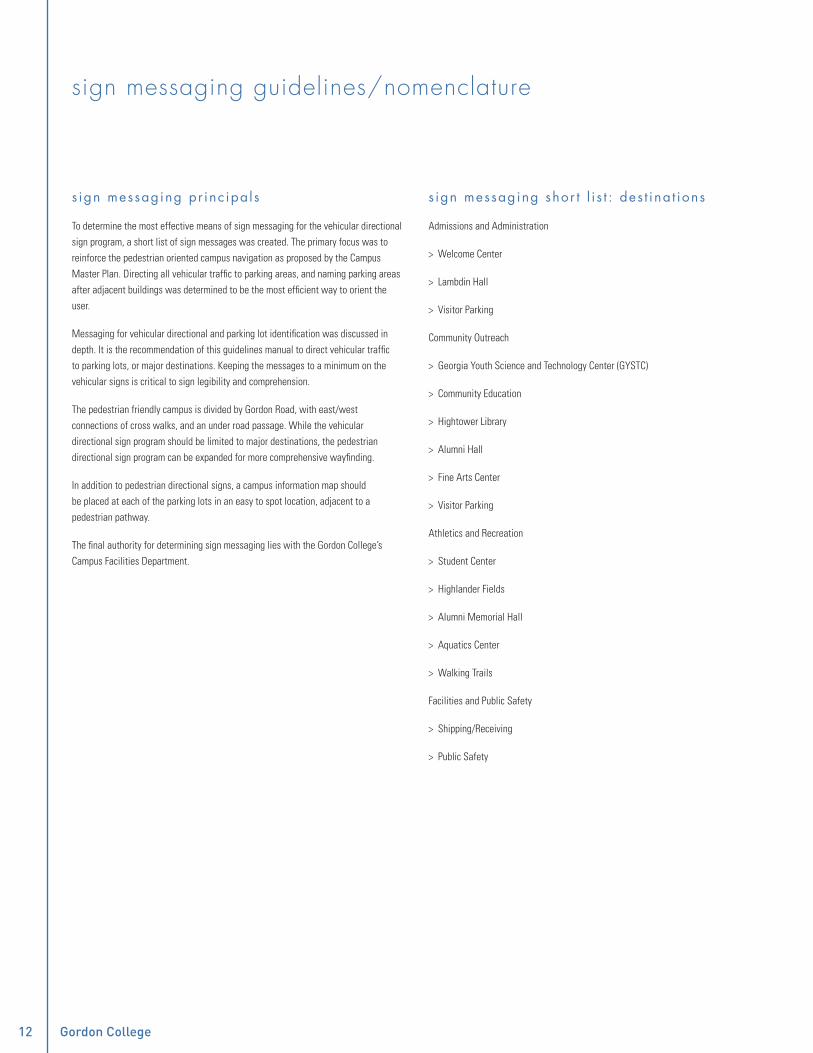
�� Gordon College Campus Sign Guidelines
sign messaging guidelines/nomenclature
s ign messaging pr inc ipa l s
To determine the most effective means of sign messaging for the vehicular directional sign program, a short list of sign messages was created. The primary focus was to reinforce the pedestrian oriented campus navigation as proposed by the Campus Master Plan. Directing all vehicular traffic to parking areas, and naming parking areas after adjacent buildings was determined to be the most efficient way to orient the user.
Messaging for vehicular directional and parking lot identification was discussed in depth. It is the recommendation of this guidelines manual to direct vehicular traffic to parking lots, or major destinations. Keeping the messages to a minimum on the vehicular signs is critical to sign legibility and comprehension.
The pedestrian friendly campus is divided by Gordon Road, with east/west connections of cross walks, and an under road passage. While the vehicular directional sign program should be limited to major destinations, the pedestrian directional sign program can be expanded for more comprehensive wayfinding.
In addition to pedestrian directional signs, a campus information map should be placed at each of the parking lots in an easy to spot location, adjacent to a pedestrian pathway.
The final authority for determining sign messaging lies with the Gordon College’s Campus Facilities Department.
s ign messaging shor t l i s t : des t ina t ions
Admissions and Administration
> Welcome Center
> Lambdin Hall
> Visitor Parking
Community Outreach
> Georgia Youth Science and Technology Center (GYSTC)
> Community Education
> Hightower Library
> Alumni Hall
> Fine Arts Center
> Visitor Parking
Athletics and Recreation
> Student Center
> Highlander Fields
> Alumni Memorial Hall
> Aquatics Center
> Walking Trails
Facilities and Public Safety
> Shipping/Receiving
> Public Safety

�� Gordon College Campus Sign Guidelines ��
sign standards: exterior
trailblazer
campus gateway
vehicular directional
parking lot identification
regulatory signs
parking lot regulations
campus directory
pedestrian directional
accessible entrance identification
building identification
restricted access identification
facility identification, and rules and regulations

�� Gordon College Campus Sign Guidelines ��
large trailblazerdescr ip t ion
The large trailblazer consists of a single sided aluminum panel attached to new post, or added to existing post structure when available. Hardware is to be painted to match the fi eld color that they reside to reduce the visual impact. All messaging should be applied in a retro-refl ective fi lm to ease in reading during the evening hours. Mile distance panels, located below the main directional panel will provide additional information to the viewer, and may also be augmented with a “downtown bypass” message, as recommended by the Sign Committee.
Trailblazing signs are intended to reinforce the path of travel from the highways exits to the campus. The large trailblazer is designed to be used on wide, higher speed roads such as Route 41.
l oca t ion gu ide l ines
As a general rule, trailblazers with an arrow pointing up should be located in advance of major intersections in order to reinforce the forward direction of travel. When indicating a turn, a trailblazer with a turned arrow should occur twice - once in advance of the turn, and again as close as possible to the turn itself.
Posts must provide a “break - away” footing as required by the Federal Highway Administration, and may not be located closer than 2’ - 0” to the roadway edge. Design and implementation of this sign type must be coordinated with Georgia Department of Transportation and the municipalities in which signs are to be placed.
10'-0
"
3'-0
"8"
2'-0"

�� Gordon College Campus Sign Guidelines
small trailblazerdescr ip t ion
The small trailblazer consists of a single sided aluminum panel attached to new post, or added to existing post structure where available. Sign panel hardware is to be painted to match the fi eld color that they reside to reduce the visual impact. All messaging should be applied in a retro-refl ective fi lm for easier visibility during evening hours. Mile distance panels, located below the main directional panel will provide additional information to the viewer, and may also be augmented with a “downtown bypass” message, as recommended by the Sign Committee.
The small trailblazer is designed to be used for slower local roads with two lane traffi c conditions, as in the downtown Barnesville region.
l oca t ion gu ide l ines
As a general rule, trailblazers with an arrow pointing up should be located in advance of major intersections in order to reinforce the forward direction of travel. When indicating a turn, a trailblazer with a turned arrow should occur twice - once in advance of the turn, and again as close as possible to the turn itself.
Signs with new posts must provide a “break - away” footing as required by the Federal Highway Administration, and may not be located closer than 2’ - 0” to the roadway edge. Design and implementation of this sign type must be coordinated with Georgia Department of Transportation and the municipalities in which signs are to be placed.
9'-0
"
2'-3
"6"
1'-6"

�� Gordon College Campus Sign Guidelines ��
campus gatewaydescr ip t ion
Single sided concave shaped aluminum pan mounted to existing brick structure, with a dimensional “Gordon College” logotype and applied vinyl graphics. Lighting to be incorporated into the landscape as needed to fl ood illuminate the entire gateway. Sign panel should be sized large enough to cover any existing holes in structure created by the removal of existing dimensional letters. While the sign panel will be mounted at a different height at north and south entrances to campus, both panels are identical in size and scale.
l oca t ion gu ide l ines
The campus gateway is, after trailblazing and web/print media, the visitor’s fi rst exposure to the campus. The primary goal of a Gateway Sign is to identify and welcome visitors and students. This sign type should be located at both north and south entrances on College Drive. A potential future location for this sign type is the intersection of Highlander Way and Gordon Road.
W E L C O M E T O
F O U N D E D 1 8 5 2
W E L C O M E T O
F O U N D E D 1 8 5 2
4'-8
" +/-
12'-0" +\-
nor th en t rance
sou th en t rance

�� Gordon College Campus Sign Guidelines
vehicular directionaldescr ip t ion
Vehicular directional signs consist of a closed back fabricated aluminum panel with applied refl ective fi lm sign messages and arrows. The fabricated panel is attached with hidden tamper resistant mechanical fasteners to an angled sign post. Two lower posts connect at the base of the sign pan to a single thicker post. The Gordon College logo is recessed and permanently attached to a “clip” at the top of the post system. In order to change the sign panel, mechanical fasteners can be removed from the back of the sign panel and the entire sign panel can be removed by sliding the panel out of its mounting posts, leaving the posts securely rooted in the foundation.
l oca t ion gu ide l ines
Vehicular directional signs should be located in advance of any major decision point on campus, to the right (or passenger) side of the intended viewer. A minimum set back from the roadway edge of 2’ - 0” should be maintained, while not encroaching on the public right of way or sidewalk. Suggested locations for vehicular directional signs are included on the sign location plan located at the end of this section of the manual. As with any sign on campus, fi nal locations must be coordinated with the Campus Facilities Department, along with an on-site review of prospective sign locations.
Facilities & ReceivingPublic Safety
Community Education
Athletics/Aquatics
Welcome Center
Alumni HouseHightower LibraryHighlander Fields
6'-5
"
8'-4
1/4
"
3'-9"

�� Gordon College Campus Sign Guidelines ��
parking lot identitydescr ip t ion
Two single sided closed back aluminum pans refl ective fi lm messaging, and parking symbol. Panels are attached to post by mechanical fasteners painted to match the surrounding fi eld of color. Parking lot identifi cation signs have been color coded for the intended users. Red coded lots are reserved for Faculty and Staff, teal for Visitors, orange for Commuter Students, and green for Students and Staff. Parking for on campus residents will be located in the lots furthest from the campus center, since the commute for residential students is within campus limits. Campus residents will park in the “Student and Staff” Parking lots.
l oca t ion gu ide l ines
Locate the Parking Lot Identity signs perpendicular to the road at the entrance(s) to each lot, while maintaining a minimum set back of 2’ - 0” from the roadway edge.
Permit required
FACULTY/STAFF
ALUMNIMEMORIAL
HALLNo Student Parking
VISITOR PARKING
WELCOMECENTER
Permit Required
COMMUTER STUDENT
GORDONVILLAGE
Permit Required
STUDENT/STAFF
HIGHLANDERFIELDS
3'-6
"
2'-3 1/2"
10'-8
"

�0 Gordon College Campus Sign Guidelines
regulatory signsdescr ip t ion
On campus regulatory signs are a single sided high intensity refl ective sign face with a custom notch in the top of the panel to maintain the “clip” system appearance. These sign panels are attached to painted, closed aluminum square tube post with mechanical fasteners painted to match the surrounding fi eld of color. These signs can be ordered from sign stock houses and the notch can be retro-fi tted onto the sign panels. Various sign panel sizes may be needed depending on varying road widths and associated speed limits.
l oca t ion gu ide l ines
Regulatory signs should be located throughout the campus as required, according to local sign code and Department of Public Works.
BPlan View - Trail Blazer
3/4" = 1'-0"
1'-1
0 1/
4"
8'-0
"
1'-6" 2'-0"

�0 Gordon College Campus Sign Guidelines ��
parking regulationsdescr ip t ion
Parking regulation signs consist of a new closed aluminum tube and aluminum panel with refl ective fi lm sign message and graphics, and silver fi lm accent border, notched at the top to maintain the clip appearance. The panel is attached to the posts with mechanical fasteners painted to match the surrounding fi eld of color.
l oca t ion gu ide l ines
Parking regulatory signs should be located within all parking lots on campus, as required by Code. Final locations for these signs should be provided by the Campus Facilities Department, along with an on-site review of prospective sign locations.
Maximum fine $500
AccessibleParking
Reserved parking for
ResidentDirector Maximum fine $500
Van AccessibleParking
1'-6
"
6'-7
"
1'-0"
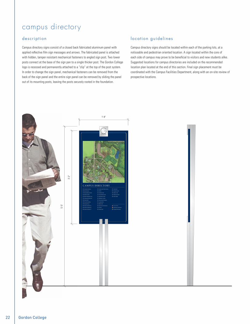
�� Gordon College Campus Sign Guidelines
campus directorydescr ip t ion
Campus directory signs consist of a closed back fabricated aluminum panel with applied refl ective fi lm sign messages and arrows. The fabricated panel is attached with hidden, tamper resistant mechanical fasteners to angled sign post. Two lower posts connect at the base of the sign pan to a single thicker post. The Gordon College logo is recessed and permanently attached to a “clip” at the top of the post system. In order to change the sign panel, mechanical fasteners can be removed from the back of the sign panel and the entire sign panel can be removed by sliding the panel out of its mounting posts, leaving the posts securely rooted in the foundation.
l oca t ion gu ide l ines
Campus directory signs should be located within each of the parking lots, at a noticeable and pedestrian oriented location. A sign located within the core of each side of campus may prove to be benefi cial to visitors and new students alike. Suggested locations for campus directories are included on the recommended location plan located at the end of this section. Final sign placement must be coordinated with the Campus Facilities Department, along with an on-site review of prospective locations.
CAMPUS DIRECTORY Academic Building
Alumni House
Alumni Memorial Hall
Aquatic Center
Beach Volleyball Court
Community Education
Connell Hall
Fine Arts Building
Georgia House
Gordon Commons A
Gordon Commons B
Gordon Commons C
Gordon Hall/Public Safety
GYSTC
Guillebau Hall
Racquetball Courts
Highlander Fields
Hightower Library
Instructional Complex
Lambdin Hall
Melton Hall
Operations & Receiving
Pavilion
Russell Hall
Smith Hall
Student Center
Watson Hall
Welcome Center
Wolf’s Walk
You are here
Emergency Call Boxes
Campus Directories
04
27
11
12
21
18
09
14
19
25
25
25
10
16
15
23
17
03
20
01
13
05
22
16
07
02
04
24
5'-5
"
3'-2
"
1'-8"
26
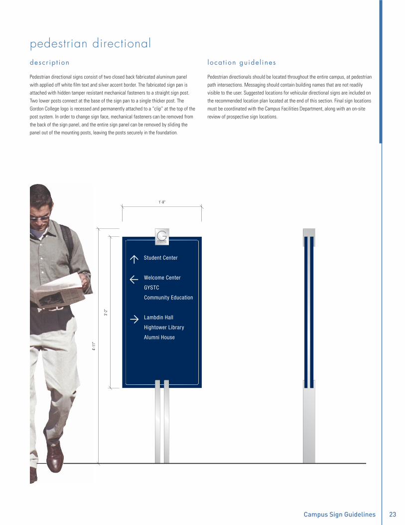
�� Gordon College Campus Sign Guidelines ��
pedestrian directionaldescr ip t ion
Pedestrian directional signs consist of two closed back fabricated aluminum panel with applied off white fi lm text and silver accent border. The fabricated sign pan is attached with hidden tamper resistant mechanical fasteners to a straight sign post. Two lower posts connect at the base of the sign pan to a single thicker post. The Gordon College logo is recessed and permanently attached to a “clip” at the top of the post system. In order to change sign face, mechanical fasteners can be removed from the back of the sign panel, and the entire sign panel can be removed by sliding the panel out of the mounting posts, leaving the posts securely in the foundation.
l oca t ion gu ide l ines
Pedestrian directionals should be located throughout the entire campus, at pedestrian path intersections. Messaging should contain building names that are not readily visible to the user. Suggested locations for vehicular directional signs are included on the recommended location plan located at the end of this section. Final sign locations must be coordinated with the Campus Facilities Department, along with an on-site review of prospective sign locations.
Student Center
Welcome Center
Community Education
Lambdin Hall
GYSTC
3'-2
"
4'-1
1"
1'-8"
Alumni House
Hightower Library

�� Gordon College Campus Sign Guidelines
accessible entrance directionaldescr ip t ion
Accessible entrance directional consist of a thin fabricated aluminum “blade” with applied fi lm graphics, and arrow.
l oca t ion gu ide l ines
Locate an accessible entrance directional at non-accessible entrances to all buildings, to help locate accessible entrances to buildings, to accessible features of the campus, such as the accessible ramp at the amphitheater.
AccessibleRamp
4 1/2"
3'-0
"
1 1/4"

�� Gordon College Campus Sign Guidelines ��
HIGHTOWER LIBRARY6" +
/-building identification: dimensional letteringdescr ip t ion
Dimensional letters on a building facade is the method preferred to identify a campus building. Dimensional letters consist of solid or manufactured metal forms which are stud mounted to an existing building façade. The letter size will need be determined by verifying locations and available space on the building facade. If there is no area of clear, open space for this sign type, one of the other alternative building identifi cation signs that follow should be used in its place.
l oca t ion gu ide l ines
Dimensional letter should be placed directly above or adjacent to primary entries to campus buildings, provided that there is a clear area of building facade. Suggested locations for building identifi cation dimensional letters are included on the sign location plan located at the end of this section. Final sign locations must be coordinated with the Campus Facilities Department, along with an on-site review of prospective sign locations.
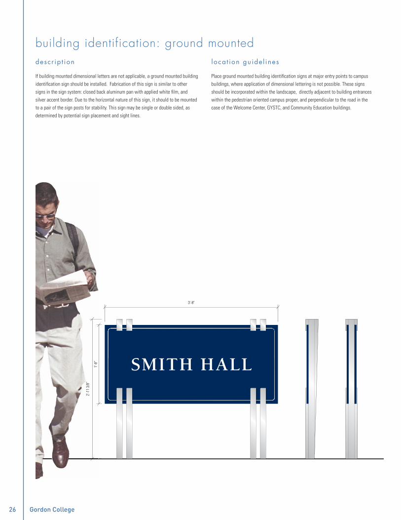
�� Gordon College Campus Sign Guidelines
building identification: ground mounteddescr ip t ion
If building mounted dimensional letters are not applicable, a ground mounted building identifi cation sign should be installed. Fabrication of this sign is similar to other signs in the sign system: closed back aluminum pan with applied white fi lm, and silver accent border. Due to the horizontal nature of this sign, it should to be mounted to a pair of the sign posts for stability. This sign may be single or double sided, as determined by potential sign placement and sight lines.
l oca t ion gu ide l ines
Place ground mounted building identifi cation signs at major entry points to campus buildings, where application of dimensional lettering is not possible. These signs should be incorporated within the landscape, directly adjacent to building entrances within the pedestrian oriented campus proper, and perpendicular to the road in the case of the Welcome Center, GYSTC, and Community Education buildings.
SMITH HALL
3'-8"
1'-8
"
2'-1
1 3/
8"

�� Gordon College Campus Sign Guidelines ��
building identification: wall mounteddescr ip t ion
Wall mounted building identifi cation signs may be used in conjunction with the other two types of building identifi cation signs. These signs are pedestrian scaled, and identify the building to people approaching the building’s main entry. The wall mounted building identifi cation consists of a fabricated aluminum pan with white fi lm text and a silver accent border. The Gordon College logo “clip” is permanently attached to the pan with hidden mechanical fasteners.
l oca t ion gu ide l ines
Place wall mounted building identifi cation signs at primary entries to buildings. These signs are not intended to be a “stand alone” building identifi cation, but are intended work in conjunction with the two other building identifi cation sign types.
1Elevation - Pedestrian Directional
1" = 1'-0"1
Elevation - Pedestrian Directional
1" = 1'-0"
ALUMNIMEMORIAL
HALL
1'-4 1/2"
10"
4'-2
"HIGHTOWER
LIBRARY
9"
1'-4 1/2"

�� Gordon College Campus Sign Guidelines
restricted access identificationdescr ip t ion
Restricted access identifi cation signs consist of a closed aluminum tube and an aluminum sign panel with white fi lm graphics and silver fi lm accent border, notched at the top to maintain the clip appearance. The panel is attached to the sign post with mechanical fasteners painted to match the surrounding fi eld of color.
l oca t ion gu ide l ines
These signs are to be placed as deemed necessary by Administration and Campus Facilities.
No Swimming
AcademicUse Only
1'-6
"
3'-0
"
1'-0"

�� Gordon College Campus Sign Guidelines ��
facility identification and rules and regulationsdescr ip t ion
Facility identifi cation and rules and regulation signs serve a dual purpose. They identify a destination and provide information about rules and regulations required to be observed during use of the facility. These signs are composed of a fabricated closed back aluminum panel, with white fi lm text, and silver accent border, mounted to a structural post with angled embellishments. Gordon College logo “clip” is permanently attached to the post structure.
l oca t ion gu ide l ines
Place facility identifi cation and rules and regulations signs at the entrance to campus facilities, (ie: Highlander Fields, and Highlander Courts). Suggested locations for these signs are included on the sign location plan located at the end of this section.
HIGHLANDERCOURTS
R U L E S A N D R E G U L AT I O N S
Gordon College student, faculty, staff and accompanied guest use only.
Proper identification required at all times.
No alcohol, tobacco, food or chewing gum allowed on courts.
No glass containers on courts.
Shirts and soft soled shoes are required.
No bicycles, roller blades or skate boardspermitted on courts.
Respect others, please limit play to 1 hour when others are waiting.
Guest passes are available with 24 hours notice from the Office of Student Affairs.
Equipment is available to check out atAlumni Memorial Hall
3'-2
"
4'-1
0 3/
4"
1'-8"

�0 Gordon College Campus Sign Guidelines
recommended campus sign location plan
PK
PK
PKPK PK
PK
PK
PK
PK
PK PK
PK
PK
PK
FINE ARTSLOT
GORDONVILLAGE
COMMONSNORTH
AQUATICSCENTER
ALUMNIMEMORIAL
HALL
GEORGIAHOUSE
ALLIEDHEALTH
MELTONHALL
HIGHLANDERFIELDS
COMMONSSOUTH
IK
IK
IK
IK
RR
RA
RA
RA
IK
RR
RR
VH
VH
VH
VH
VH
VH
VH
BG
BG
BG
BG
BG
BG
BGBG
BG
BG
BG
BG
BG
BG
BG
BG
BL
BL
BL
BL
BL
BL
BL
BLBL
PD
PD
PD
PD
PDPD
RA Restricted Access Identificaion
RR Facility Identity Rules and Regulations
IK Campus Information Kiosk
Building Identificaion: Ground MountedBG
Building Identificaion: Dimensional LetteringBLPK Parking Lot Identificaion
Vehicular DirectionalVH
Pedestrian DirectionalPD

�0 Gordon College Campus Sign Guidelines ��
sign standards: interior
building directory
elevator identification
restroom identification
department identification
office/personnel identification
classroom/meeting room identification
utility room identification
exit stair identification
stair level identification
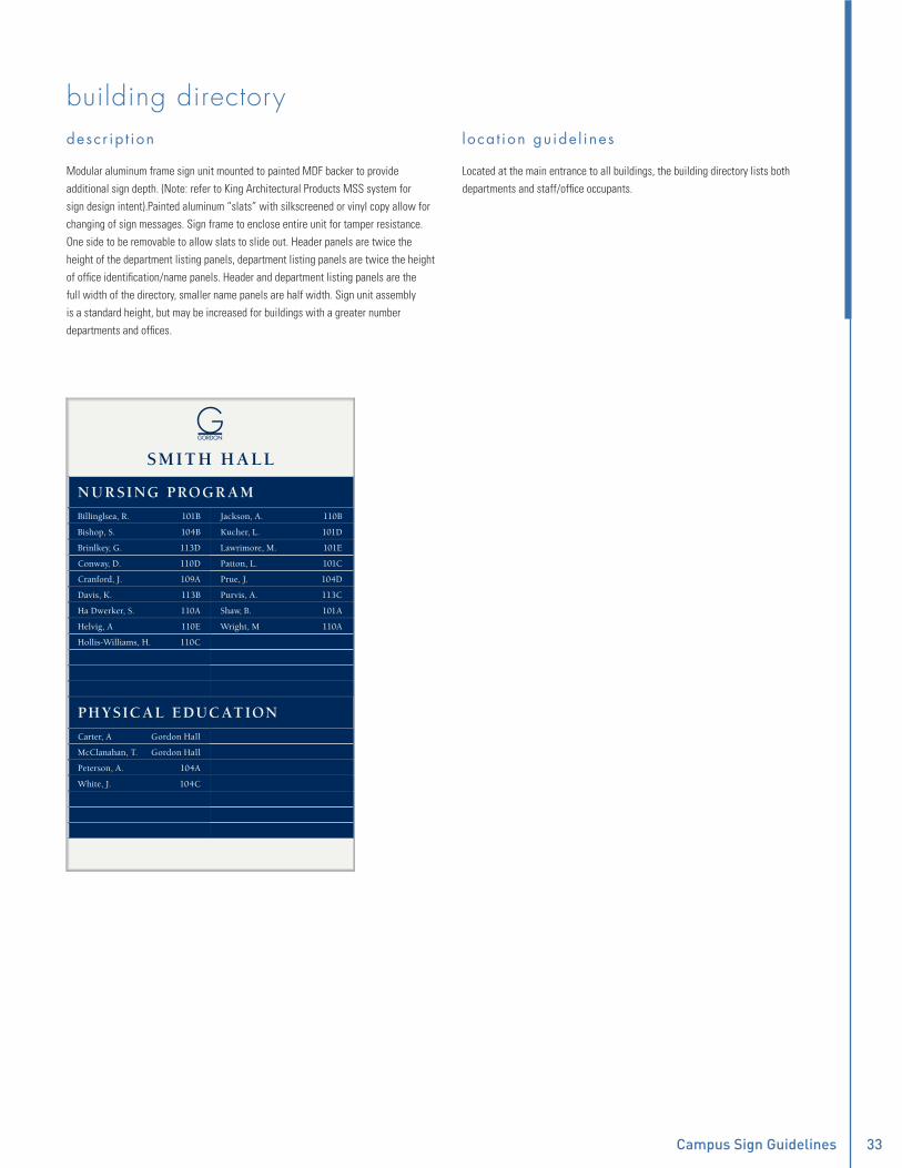
�� Gordon College Campus Sign Guidelines ��
building directorydescr ip t ion
Modular aluminum frame sign unit mounted to painted MDF backer to provide additional sign depth. (Note: refer to King Architectural Products MSS system for sign design intent).Painted aluminum “slats” with silkscreened or vinyl copy allow for changing of sign messages. Sign frame to enclose entire unit for tamper resistance. One side to be removable to allow slats to slide out. Header panels are twice the height of the department listing panels, department listing panels are twice the height of offi ce identifi cation/name panels. Header and department listing panels are the full width of the directory, smaller name panels are half width. Sign unit assembly is a standard height, but may be increased for buildings with a greater number departments and offi ces.
l oca t ion gu ide l ines
Located at the main entrance to all buildings, the building directory lists both departments and staff/offi ce occupants.
Billinglsea, R.
Bishop, S.
Brinlkey, G.
Conway, D.
Cranford, J.
Davis, K.
Ha Dwerker, S.
Helvig, A
Hollis-Williams, H.
101B
104B
113D
110D
109A
113B
110A
110E
110C
Jackson, A.
Kucher, L.
Lawrimore, M.
Patton, L.
Prue, J.
Purvis, A.
Shaw, B.
Wright, M
Carter, A
McClanahan, T.
Peterson, A.
White, J.
Gordon Hall
Gordon Hall
104A
104C
110B
101D
101E
101C
104D
113C
101A
110A
NUR SING PROGR AM
SMITH H ALL
PH YSICAL EDUCATION

�� Gordon College Campus Sign Guidelines
elevator identification: elevator jambdescr ip t ion
Elevator jamb identifi cation signs are required by building code, fabricated with a photopolymer base panel with Grade 2 braille, and and additional panel (included as part of the “clip” design vocabulary) with a raised fl oor number. A star symbol should be used for the exit/entrance fl oor level.
l oca t ion gu ide l ines
Placed in the elevator door jambs, these signs are to be centered within the jamb, with a distance of 5’ - 0” to the baseline of the dimensional fl oor number.
2" 22 3/
4"7/
8"
3 5/
8"
4 1/8"
3 5/8" 2"
2 1/2"
Upper panel
Raised numberal and symbol as required
Lower panel
Grade 2 braille
Aluminum backer panel

�� Gordon College Campus Sign Guidelines ��
elevator identification: wall mounteddescr ip t ion
The elevator identifi cation sign, along with the elevator jamb identifi cation, are the minimum required signs for all elevators serving a building or wing. The sign consists of a stepped photopolymer sign panel with a raised symbol, and a second photopolymer base panel containing the “elevator” text in addition to Grade 2 braille required by code. The message should be augmented with an alpha character for buildings with multiple elevators, or banks of elevators (ie: Elevator A, and Elevator B, for a building containing 2 elevators at separate locations, with separate call buttons).
l oca t ion gu ide l ines
Place sign directly above the elevator call button panel, 5’- 0” on center as required by local Building Code.
5"
7"
1/2" 1 1/2"
8 1/
2"
6"
Upper panel
Raised painted symbol
Lower panel
Raised text and Grade 2 braille
Alumnimum backer panel
3/8"

�� Gordon College Campus Sign Guidelines
elevator identification: projectingdescr ip t ion
The projecting elevator identifi cation is the third part of the elevator identifi cation system. This sign consists of a painted aluminium frame with a fabricated acrylic sign panel with applied pressure sensitive fi lm graphics. Mounted perpendicular to the wall surface, the viewer is able to see the sign “blade” from a distance. Code requires this sign to be placed a minimum clearance of 7’-2” to the bottom of the sign, which requires that the sign only be used in conditions where the ceiling is 8’-0” or higher.
l oca t ion gu ide l ines
Place sign on wall above call buttons, and above wall mounted elevator sign.
1 5/8"1'-5 1/2"
1'-2 7/8"
7 1/
4"
8 1/
4"
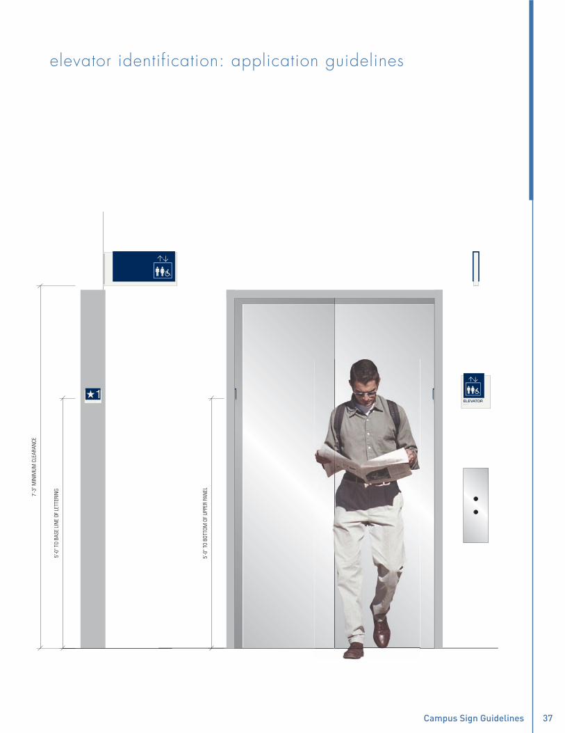
�� Gordon College Campus Sign Guidelines ��
elevator identification: projecting elevator identification: application guidelines5'
-0" T
O BA
SE L
INE
OF L
ETTE
RIN
G
5'-0
" TO
BOTT
OM O
F UP
PER
PAN
EL
7'-3
" MIN
IMUM
CLE
ARAN
CE
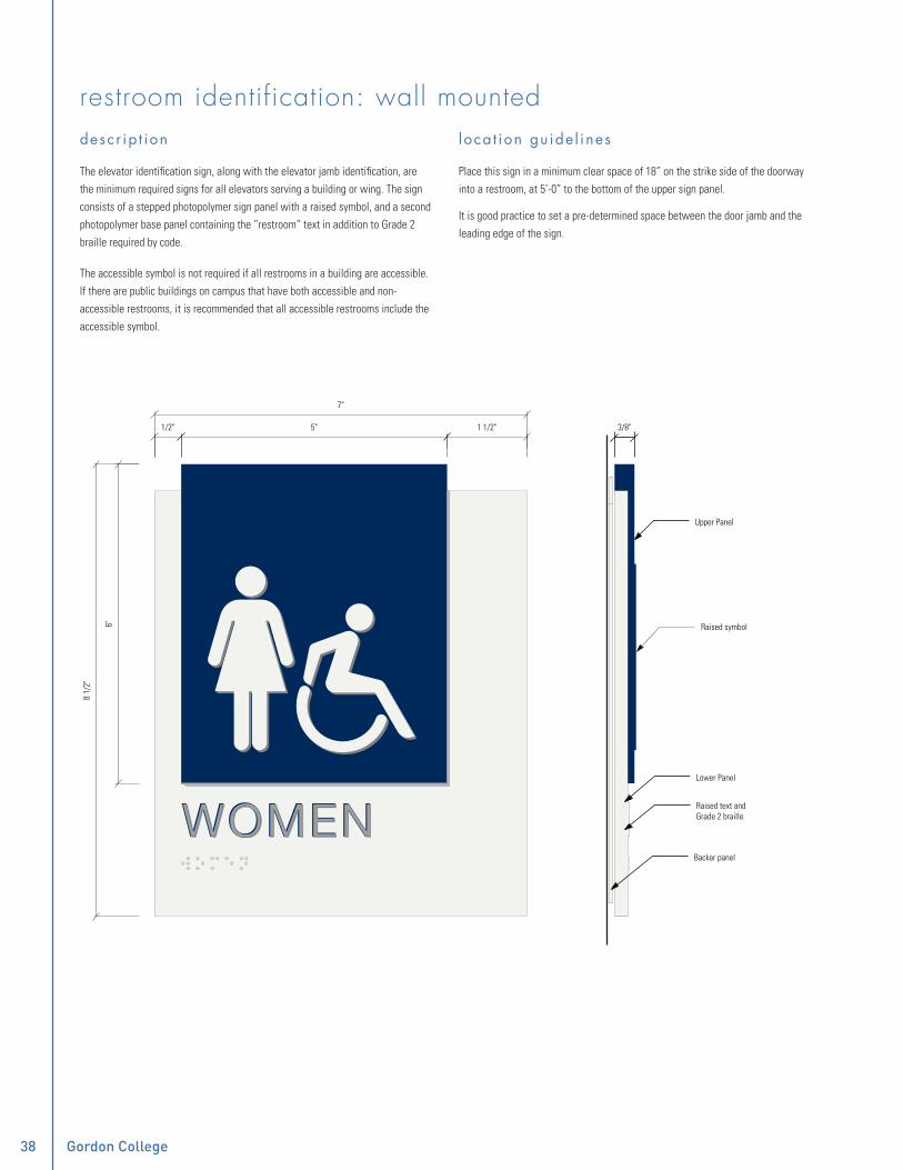
�� Gordon College Campus Sign Guidelines
restroom identification: wall mounteddescr ip t ion
The elevator identifi cation sign, along with the elevator jamb identifi cation, are the minimum required signs for all elevators serving a building or wing. The sign consists of a stepped photopolymer sign panel with a raised symbol, and a second photopolymer base panel containing the “restroom” text in addition to Grade 2 braille required by code.
The accessible symbol is not required if all restrooms in a building are accessible. If there are public buildings on campus that have both accessible and non-accessible restrooms, it is recommended that all accessible restrooms include the accessible symbol.
l oca t ion gu ide l ines
Place this sign in a minimum clear space of 18” on the strike side of the doorway into a restroom, at 5’-0” to the bottom of the upper sign panel.
It is good practice to set a pre-determined space between the door jamb and the leading edge of the sign.
5"
7"
1/2" 1 1/2"
8 1/
2"
6"
Upper Panel
Lower Panel
Raised text and Grade 2 braille
Backer panel
3/8"
Raised symbol

�� Gordon College Campus Sign Guidelines ��
restroom identification: projectingdescr ip t ion
The projecting restroom identifi cation is the second part of the restroom identifi cation system. This sign consists of a painted aluminium frame with a fabricated acrylic “clip” sign panel with an applied pressure sensitive fi lm. Mounted perpendicular to the wall surface, the viewer is able to see the sign “blade” from a distance. Code requires this sign to be placed a minimum clearance of 7’-2” to the bottom of the sign, which requires that the sign only be used in conditions where the ceiling is 8’-0” or higher.
l oca t ion gu ide l ines
Place on the strike side of door above the wall mounted restroom identifi cation. In the case of a recessed restroom entry, place sign on the wall in the corridor closest to the entrance to the restroom.
1 5/8"1'-5 1/2"
1'-2 7/8"
7 1/
4"
8 1/
4"

�0 Gordon College Campus Sign Guidelines
restroom identification: application guidelines
5'-0
" TO
BOTT
OM O
F UP
PER
PAN
EL
7'-3
" MIN
IMUM
CLE
ARAN
CE

�0 Gordon College Campus Sign Guidelines ��
department identificationdescr ip t ion
The department identifi cation sign type consists of a stepped photopolymer sign panel that contains the room number and Grade 2 braille, and a second photopolymer base panel with recessed type, indicating the name of the department.
l oca t ion gu ide l ines
It is intended that this sign type is located outside of a suite of offi ces, or outside a permanently designated room, such as the Registrar’s Offi ce.
Place these signs within a minimum clear space of 18” on the strike side of doorway into a department or suite of offi ces, and 5’-0” to the bottom of the upper sign panel. It is good practice to set a pre-determined space between the jamb and leading edge of the sign.
AdvancementOffice of Academic
8 1/2"
4 1/4" 3 7/8"3/8"
4 3/
8"
3/8"
3/8"
Upper Panel
Lower Panel
Backer panel
AdvancementOffice of Academic AdvancementOffice of Academic

�� Gordon College Campus Sign Guidelines
office personnel identificationdescr ip t ion
The offi ce personnel identifi cation consists of a stepped photopolymer sign panel that contains the room number and Grade 2 braille, and an assembled insert window panel to receive a laser printed insert with the occupant’s name and title.
l oca t ion gu ide l ines
It is the intent of this sign to indicate the building assigned room number and allow for updating as room occupant changes.
Locate these signs in a minimum clear space of 18” on the strike side of doorways into offi ces, at 5’-0” to the bottom of the upper sign panel. In the case of a side light application, back up the sign with a pressure sensitive fi lm backer to conceal the mounting adhesive. It is good practice to set a pre-determined space between the jamb and leading edge of the sign.
8 1/2"
4 1/4" 3 7/8"3/8"
4 3/
8"
3/8"
3/8"
Upper Panel
Lower Panel
Backer panel
325A325A325A
Ms. Rhonda ToonVice President of Advancement
Ms. Rhonda ToonVice President of Advancement

�� Gordon College Campus Sign Guidelines ��
classroom/meeting room identificationdescr ip t ion
The classroom/meeting room sign consists of a stepped photopolymer sign panel that contains the room number and Grade 2 braille, and a second lower photopolymer base panel with recessed type, indicating the room function.
This sign type has an engraved recess in the back of the base panel housing an aluminium roller bar that allows a piece of paper to be slid between the sign’s aluminum backer and the bar. This allows placement of temporary, removable notices under the sign.
l oca t ion gu ide l ines
Place this sign a minimum clear space of 18” on the strike side of the doorway into a classroom or meeting room, at 5’-0” to the bottom of the upper sign panel. In the case of a side light application, back up the sign with a pressure sensitive fi lm backer to conceal the mounting adhesives. It is good practice to set a pre-determined space between the jamb and the leading edge of the sign.
Meeting Room A
8 1/2"
4 1/4" 3 7/8"3/8"
4 3/
8"
3/8"
3/8"
Upper Panel
Lower Panel
Backer panel
145145145
Paper holder
AdvancementOffice of Academic AdvancementOffice of Academic

�� Gordon College Campus Sign Guidelines
utility room identificationdescr ip t ion
The utility room identifi cation sign type consists of a stepped photopolymer sign panel that contains the room number and Grade 2 braille, and a second base photopolymer sign panel with recessed type, indicating the room function.
These signs are the smallest of the room identifi cation signs. This sign type is intended for electrical rooms, elevator machine rooms, janitor closets, and back of house rooms and spaces.
l oca t ion gu ide l ines
Place this sign in a minimum clear space of 18” on the strike side of the doorway into a room at 5’-0” to the bottom of the upper sign panel. It is good practice to set a pre-determined space between the jamb and leading edge of the sign.
8 1/2"
4 1/4" 3 7/8"3/8"
3/8"
3/8"
Upper Panel
Lower Panel
Backer panel
3 1/
8"
AdvancementOffice of Academic AdvancementOffice of Academic

�� Gordon College Campus Sign Guidelines ��
room identification: application guidelines
5'-0
" TO
BOTT
OM O
F UP
PER
PAN
EL

�� Gordon College Campus Sign Guidelines
exit stair identificationdescr ip t ion
The exit stair identifi cation consists of a stepped photopolymer sign panel with a raised symbol and arrow, and a second photopolymer base panel with raised type and Grade 2 braille. This sign type is required by code to identify egress stairways, in buildings greater than three fl oors. It is part of a two sign system, including the stair level identifi cation.
l oca t ion gu ide l ines
Locate this sign in a minimum clear space of 18” on occupant strike side of a doorway leading to stairs, at 5’-0” to the bottom of the upper sign panel. It is good practice to set a pre-determined space between the jamb and leading edge of the sign.
8 1/
2"
6"
Upper Panel
Lower Panel
Backer panel
3/8"
EXIT STAIR 2EXIT STAIR 2
7 1/2"
5 1/2" 1 1/2"1/2"
STAIR 2

�� Gordon College Campus Sign Guidelines ��
stair level identification: alternate adescr ip t ion
The stair level identifi cation consists of a stepped photopolymer sign panel with a raised numeral, and a second photopolymer base panel with raised type and Grade 2 braille. This sign type informs people within the stairway of building under three stories which fl oor they are currently on. (In buildings with three or more fl oors, it is a requirement that alternate b is installed.)
l oca t ion gu ide l ines
Locate these signs in a minimum clear space of 18” on the strike side of doorways on the stair side, at 5’-0” to the bottom of the upper sign panel. It is good practice to set a pre-determined space between the jamb and leading edge of the sign.
8 1/
2"
6"
Upper Panel
Lower Panel
Backer panel
3/8"
LEVEL 1LEVEL 1
7 1/2"
5 1/2" 1 1/2"1/2"
111
LEVEL 2
EXIT LEVEL 1
2LEVEL 1
EXIT
1

�� Gordon College Campus Sign Guidelines
stair level identification: alternate bdescr ip t ion
The stair level identifi cation consists of a stepped photopolymer sign panel with a raised numeral, and a second photopolymer base panel with raised type and Grade 2 braille. This sign type informs people within the stairway of buildings with three stories or more which fl oor they are currently on and what fl oor to exit the building in case of emergency. While alternate a is not required, this sign type is required by code, and depending on code offi cials, may be required to indicate roof accessibility.
l oca t ion gu ide l ines
Locate these signs in a minimum clear space of 18” on the strike side of doorways on the stair side of stair enclosure, at 5’-0” to the bottom of the upper sign panel. It is good practice to set a pre-determined space between the jamb and leading edge of the sign.
6"
Upper Panel
3/8"
LEVEL 1
7 1/2"
5 1/2" 1 1/2"1/2"
1LEVEL 2LEVEL 2
22EXIT LEVEL 1EXIT LEVEL 1
210 1
/2"
Lower Panel
Backer panel
LEVEL 1
EXIT
1
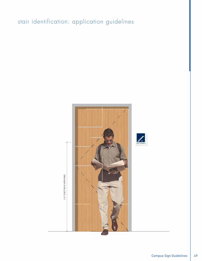
�� Gordon College Campus Sign Guidelines ��
stair identification: application guidelines
5'-0
" TO
BOTT
OM O
F UP
PER
PAN
EL
EXIT STAIR 2EXIT STAIR 2

�� Gordon College
Prepared by:

1419 / J-241 / Renovation of Hightower Library
12 2400 - 1 ROLLER WINDOW SHADES
SECTION 12 2400
ROLLER WINDOW SHADES
PART 1 GENERAL
1.01 SECTION INCLUDES
A. Window shades and accessories.
B. Electric motor operators.
C. Motor controls.
1.02 RELATED REQUIREMENTS
A. Section 26 2726 - Wiring Devices: Finish requirements for wall controls specified in this section.
1.03 REFERENCE STANDARDS
A. ASTM D4674 - Standard Practice for Accelerated Testing for Color Stability of Plastics Exposed to Indoor Office Environments; 2002a (Reapproved 2010).
B. NFPA 701 - Standard Methods of Fire Tests for Flame Propagation of Textiles and Films; 2010.
C. UL 325 - Standard for Door, Drapery, Gate, Louver, and Window Operators and Systems; Current Edition, Including All Revisions.
1.04 ADMINISTRATIVE REQUIREMENTS
A. Coordination:
1. Coordinate the work with other trades to provide rough-in of electrical wiring as required for installation of hardwired motorized shades.
B. Sequencing:
1. Do not fabricate shades until field dimensions for each opening have been taken.
2. Do not install shades until final surface finishes and painting are complete.
1.05 SUBMITTALS
A. See Section 01 3000 - Administrative Requirements, for submittal procedures.
B. Product Data: Provide manufacturer's standard catalog pages and data sheets including materials, finishes, fabrication details, dimensions, profiles, mounting requirements, and accessories.
1. Motorized Shades: Include power requirements and standard wiring diagrams.
C. Shop Drawings - Motorized Shades: Provide schematic system riser diagram indicating component interconnections. Include requirements for interface with other systems.
D. Selection Samples: Include fabric samples in full range of available colors and patterns.
E. Verification Samples: Minimum size 6 inches (150 mm) square, representing actual materials, color and pattern.
1.06 QUALITY ASSURANCE
A. Manufacturer Qualifications: Company specializing in manufacturing products specified in this section, with not less than five years of experience.
1.07 WARRANTY
A. See Section 01 7800 - Closeout Requirements, for additional warranty requirements.
B. Provide manufacturer's warranty from the Date of Substantial Completion, covering the following:
1. Shade Hardware: One year.
2. Electric Motors: One year.
3. Fabric: One year.

100% CONSTRUCTION DOCUMENTS
1419 / J-241 / Renovation of Hightower Library
12 2400 - 2 ROLLER WINDOW SHADES 04/29/15 06/26/15 Addendum #1
PART 2 PRODUCTS
2.01 MANUFACTURERS
A. Manually Operated Roller Shades:
1. Draper, Inc; Clutch Operated FlexShade: www.draperinc.com.
2. Basis of Design: Lutron Electronics Co., Inc; www.lutron.com.
3. Hunter Douglas; www.hunterdouglas.com.
4. Substitutions: See Section 01 6000 – Product Requirements.
B. Motorized Roller Shades, Motors and Motor Controls:
1. Draper, Inc; Motorized FlexShade: www.draperinc.com.
2. Basis of Design: Lutron Electronics Co., Inc; Sivoia QS Roller Shades: www.lutron.com.
3. Nysan Solar Control, Inc., a division of Hunter Douglas; ______: www.nysan.com.
4. Substitutions: See Section 01 6000 – Product Requirements.
2.02 WINDOW SHADE APPLICATIONS
A. Shades: Sheer shades.
1. Type: Roller shades.
2. Fabric: 3% openness. Basketweave 90.
3. Color: As selected by Houser Walker Architecture from manufacturer’s full range of colors.
4. Mounting: Inside (between jambs).
5. Operation: Manual and motorized, in locations indicated.
2.03 ROLLER SHADES
A. Roller Shades: Fabric roller shades complete with mounting brackets, roller tubes, hembars, hardware and accessories; fully factory-assembled.
1. Drop: Regular roll.
2. Size: As indicated on drawings.
B. Fabric: Non-flammable, color-fast, impervious to heat and moisture, and able to retain its shape under normal operation; PVC-free; 100 percent recycled.
1. Sheer Shades: Reduce glare yet still reveal considerable details to the outside; no privacy; Openness Factor greater than 1 percent.
2. Flammability: Pass NFPA 701 large and small tests.
C. Roller Tube: As required for type of operation, extruded aluminum with end caps.
1. Fabric Attachment: Utilize extruded channel in tube to accept vinyl spline welded to fabric edge.
D. Hembars and Hembar Pockets: Wall thickness designed for weight requirements and adaptation to uneven surfaces, to maintain bottom of shade straight and flat.
E. Manual Operation: Clutch operated continuous loop; beaded ball chain.
F. Motor Operation: Motor system housed inside roller tube, controlling shade movement via motor controls indicated; listed to UL 325.
1. Audible Noise: Maximum 39 dBA measured 3 feet from the motor unit; no audible clicks when motor starts and stops.
2. Motors: Size and configuration as recommended by manufacturer for the type, size, and arrangement of shades to be operated; integrated into shade operating components and concealed from view.
3. Motor Type: Both AC and DC motors are acceptable; provide required transformers for DC motors.
4. Control Compatibility: Fully compatible with the controls to be installed.
2.04 MOTOR CONTROLS
A. Motorized shades to be controlled by wall-mounted controls as specified below.
B. Control Requirements:

100% CONSTRUCTION DOCUMENTS
1419 / J-241 / Renovation of Hightower Library
12 2400 - 3 ROLLER WINDOW SHADES 04/29/15 06/26/15 Addendum #1
1. Unless specifically indicated to be excluded, provide all required equipment, conduit, boxes, wiring, connectors, hardware, supports, accessories, software, system programming, etc. as necessary for a complete operating system that provides the control intent indicated.
C. Wall-Mounted Controls: UV stabilized visible parts meeting ASTM D4674; furnished with backlit buttons; provided by shade manufacturer.
1. Control Functions:
a. Open: Automatically open controlled shade(s) to fully open position when button is pressed.
b. Close: Automatically close controlled shade(s) to fully closed position when button is pressed.
c. Raise: Raise controlled shade(s) only while button is pressed.
d. Lower: Lower controlled shade(s) only while button is pressed.
e. Stop shade(s) in motion by tap on any button.
2. Finish: As specified in Section 26 2726.
3. Button Engraving: Manufacturer's standard engraving, unless otherwise indicated.
2.05 ACCESSORIES
A. Fascias: Size as required to conceal shade mounting.
1. Style: As indicated on the drawings.
B. Brackets and Mounting Hardware: As recommended by manufacturer for mounting configuration and span indicated.
C. Fasteners: Non-corrosive, and as recommended by shade manufacturer.
2.06 FABRICATION
A. Field measure finished openings prior to ordering or fabrication.
B. Fabricate shades to fit openings within specified tolerances.
1. Vertical Dimensions: Fill openings from head to sill with 1/2 inch (13 mm) space between bottom bar and window stool.
C. Dimensional Tolerances: As recommended in writing by manufacturer.
PART 3 EXECUTION
3.01 EXAMINATION
A. Examine finished openings for deficiencies that may preclude satisfactory installation.
B. If substrate preparation is the responsibility of another installer, notify Houser Walker Architecture of unsatisfactory preparation before proceeding.
3.02 PREPARATION
A. Prepare surfaces using methods recommended by manufacturer for achieving best result for substrate under the project conditions.
B. Coordinate with window installation and placement of concealed blocking to support shades.
3.03 INSTALLATION
A. Install in accordance with manufacturer's instructions and approved shop drawings, using mounting devices as indicated.
B. Installation Tolerances:
1. Maximum Offset From Level: 1/16 inch (1.5 mm).
C. Adjust level, projection and shade centering from mounting bracket. Verify there is no telescoping of shade fabric. Ensure smooth shade operation.
3.04 SYSTEM STARTUP
A. Motorized Shade System: Provide services of a manufacturer's authorized representative to perform system startup.
100% CONSTRUCTION DOCUMENTS
1419 / J-241 / Renovation of Hightower Library
12 2400 - 4 ROLLER WINDOW SHADES 04/29/15 06/26/15 Addendum #1
3.05 CLEANING
A. Clean soiled shades and exposed components as recommended by manufacturer.
B. Replace shades that cannot be cleaned to "like new" condition.
3.06 CLOSEOUT ACTIVITIES
A. See Section 01 7900 - Demonstration and Training, for additional requirements.
B. Demonstration: Demonstrate operation and maintenance of window shade system to Owner's personnel.
C. Training: Train Owner's personnel on operation and maintenance of system.
1. Use operation and maintenance manual as training reference, supplemented with additional training materials as required.
2. Provide minimum of two hours training by manufacturer's authorized personnel at location designated by the Owner.
3.07 PROTECTION
A. Protect installed installed products from subsequent construction operations.
B. Touch-up, repair or replace damaged products before Substantial Completion.
END OF SECTION

100% CONSTRUCTION DOCUMENTS
1419 / J-241 / Renovation of
Hightower Library
22 400022 4000 - 1 PLUMBING FIXTURES AND
TRIMPLUMBING FIXTURES AND TRIM
04/29/1506/26/15 Revised - Addendum
1
SECTION 22 4000
PLUMBING FIXTURES AND TRIM
PART 1 GENERAL
1.01 DESCRIPTION: This section specifies the fixtures and trim requirements.
1.02 RELATED SECTIONS:
A. Section 22 0010 General Provisions - Plumbing
B. Section 22 0100 Operation and Maintenance of Plumbing
C. Section 22 0500 Common Work Results for Plumbing
D. Section 22 0523 Plumbing Valves and Strainers
E. Section 22 1000 Pipe, Fittings and Accessories - Plumbing
F. Section 22 1005 Plumbing Piping and Drainage Accessories
G. Section 22 1125 Pumps - Plumbing
H. Section 22 0700 Mechanical Systems Insulation - Plumbing
1.03 SUBMITTALS:
A. See General Conditions for submittal procedure.
B. Provide product data for all fixtures; including catalog illustrations, dimensions, pipe connection sizes, and associated trim.
C. Provide manufacturer’s instructions, indicate installation and support requirements.
D. Provide operation and maintenance data; include start-up instructions, assembly drawings and parts list.
1.04 QUALITY ASSURANCE:
A. All fixtures shall have the manufacturer's guarantee; label or trademark indicating specified quality. All Acid Resisting enamel shall bear the manufacturer's symbol signifying Acid Resisting material.
B. All water closets, lavatories, and urinals shall be by the same manufacturer. All sinks shall be by the same manufacturer.
C. All fixtures construction components, tanks, and joints shall be of lead free material and construction. All drinking fountains and all faucets shall meet NSF Standard 61 and shall be certified to meet the standard requirements by NSF or U.L.
D. Fixtures shall be white in color and all spaces between the fixture and the wall or floor shall be filled with white, mildew resistant, non-hardening silicone caulking.
PART 2 PRODUCTS
2.01 FIXTURES shall be complete with all equipment, fittings, and trim. Fittings and trim shall be chrome plated brass unless specified otherwise, including P-traps, supplies and stops.
2.02 FIXTURE SCHEDULE:
A. Fixtures shall be as follows: based on American Standard, except where otherwise indicated. Comparable Zurn, or Kohler fixtures will be acceptable. Seats are based on Church; comparable, or Bemis or Olsonite seats are acceptable. Trim is based on Chicago manufacture; comparable Speakman, T&S Brass, Delta, Moen or trim made by the fixture manufacturer will be acceptable. Flush valves are based on Sloan; comparable Zurn or flush valves by the fixture manufacturer will be acceptable. Stainless Steel sinks shall be Just manufacturer; comparable Elkay or Advance Tabco fixtures are acceptable. Drinking Fountains shall be Oasis manufacturer; comparable fixtures by Acorn Aqua or Elkay are acceptable. Stops, traps and tailpieces shall be by one manufacturer, McGuire or Engineered Brass. Drain, trap, and supply insulation under ADA fixtures shall comply with ASTM E84 and 25 Flame/450 Smoke rating may be provided by Plumberex- Handy Shield or by comparable others.
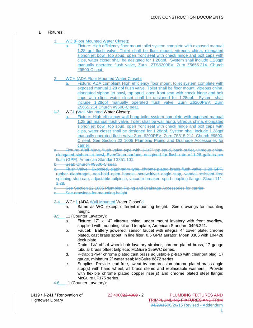
100% CONSTRUCTION DOCUMENTS
1419 / J-241 / Renovation of
Hightower Library
22 400022 4000 - 2 PLUMBING FIXTURES AND
TRIMPLUMBING FIXTURES AND TRIM
04/29/1506/26/15 Revised - Addendum
1
B. Fixtures:
1. WC (Floor Mounted Water Closet): a. Fixture: High efficiency floor mount toilet system complete with exposed manual
1.28 gpf flush valve. Toilet shall be floor mount, vitreous china, elongated siphon jet bowl, top spud, open front seat with check hinge and bolt caps with clips, water closet shall be designed for 1.28gpf. System shall include 1.28gpf manually operated flush valve, Zurn ZTS6200EV; Zurn Z5655.214. Church #9500-C seat.
2. WCH (ADA Floor Mounted Water Closet): a. Fixture: ADA compliant High efficiency floor mount toilet system complete with
exposed manual 1.28 gpf flush valve. Toilet shall be floor mount, vitreous china, elongated siphon jet bowl, top spud, open front seat with check hinge and bolt caps with clips, water closet shall be designed for 1.28gpf. System shall include 1.28gpf manually operated flush valve, Zurn Z6200PEV; Zurn Z5665.214 Church #9500-C seat.
1.3. WC1 (Wall Mounted Water Closet): a. Fixture: High efficiency wall hung toilet system complete with exposed manual
1.28 gpf manual flush valve. Toilet shall be wall hung, vitreous china, elongated siphon jet bowl, top spud, open front seat with check hinge and bolt caps with clips, water closet shall be designed for 1.28gpf. System shall include 1.28gpf manually operated flush valve Zurn 6200PEV; Zurn Z5615.214. Church #9500-C seat. See Section 22 1005 Plumbing Piping and Drainage Accessories for carrier.
a. Fixture: Wall hung, flush valve type with 1-1/2" top spud, back outlet, vitreous china, elongated siphon jet bowl, EverClean surface, desgined for flush rate of 1.28 gallons per flush (GPF); American Standard 3351.101.
b. Seat: Church #9500-C seat. c. Flush Valve: Exposed, diaphragm type, chrome plated brass flush valve, 1.28 GPF, rubber diaphragm, non-hold open handle, screwdriver angle stop, vandal resistant free spinning stop cap, adjustable tailpiece, vacuum breaker, spud coupling flange, Sloan 111-1.28.
d. See Section 22 1005 Plumbing Piping and Drainage Accessories for carrier. e. See drawings for mounting height
2.4. WCH1 (ADA Wall Mounted Water Closet):" a. Same as WC, except different mounting height. See drawings for mounting
height. 3.5. L1 (Counter Lavatory):
a. Fixture: 17” x 14” vitreous china, under mount lavatory with front overflow, supplied with mounting kit and template; American Standard 0495.221.
b. Faucet: Battery powered, sensor faucet with integral 4” cover plate, chrome plated, cast brass spout, in line filter, 0.5 GPM aerator; Moen 8305 with 104428 deck plate.
c. Drain: 1¼” offset wheelchair lavatory strainer, chrome plated brass, 17 gauge tubular brass offset tailpiece; McGuire 155WC series.
d. P-trap: 1-1/4” chrome plated cast brass adjustable p-trap with cleanout plug, 17 gauge, minimum 2” water seal; McGuire 8872 series.
e. Supplies: Provide lead free, sweat by compression chrome plated brass angle stop(s) with hand wheel, all brass stems and replaceable washers. Provide with flexible chrome plated copper riser(s) and chrome plated steel flange; McGuire LF175 series.
4.6. L1 (Counter Lavatory):

100% CONSTRUCTION DOCUMENTS
1419 / J-241 / Renovation of
Hightower Library
22 400022 4000 - 3 PLUMBING FIXTURES AND
TRIMPLUMBING FIXTURES AND TRIM
04/29/1506/26/15 Revised - Addendum
1
a. Fixture: 17” x 14” vitreous china, under mount lavatory with front overflow, supplied with mounting kit and template; American Standard 0495.221.
b. Faucet: Battery powered, sensor faucet with integral 4” cover plate, chrome plated, cast brass spout, in line filter, 0.5 GPM aerator; Moen 8305 with 104428 deck plate.
c. Drain: 1¼” offset wheelchair lavatory strainer, chrome plated brass, 17 gauge tubular brass offset tailpiece; McGuire 155WC series.
d. P-trap: 1-1/4” chrome plated cast brass adjustable p-trap with cleanout plug, 17 gauge, minimum 2” water seal; McGuire 8872 series.
e. Supplies: Provide lead free, sweat by compression chrome plated brass angle stop(s) with hand wheel, all brass stems and replaceable washers. Provide with flexible chrome plated copper riser(s) and chrome plated steel flange; McGuire LF175 series.
f. Accessories: provide waste and supply piping covers on drain, trap and water supplies under lavatory to satisfy ADA compliance requirements; TruBro LavGuard 103 E-Z.
5.7. L3 (ADA Wall Hung Lavatory): a. Fixture: 20" x 18" wall hung, vitreous china lavatory, 4" faucet centers;
American Standard 0355.012. b. Faucet: " center set, one-handle, with ½ GPM aerator; Moen 8413F05. c. Drain: Chicago 327 grid drain with 1¼” offset tailpiece and chrome plated 17
gauge cast brass P-trap with cleanout. d. Supplies: Provide supplies to wall with wheel handle angle stops. e. Accessories: Provide rigid PVC, vandal resistant, ADA insulation kit on piping
under lavatory. f. See Section 22 1005 Plumbing Piping and Drainage Accessories for carrier.
6.8. S1 (ADA Stainless Steel Counter Sink): a. Fixture: Single compartment, 18 gauge, self rimming, type 304 stainless steel
sink, 20” x 17” x 6½” deep; Just SL-ADA-2017-A-GR with J-35 basket strainer. b. Faucet: 4” centers, gooseneck spout, wrist blade handles; Chicago 895-
317CP. c. Drain: Provide supplies to wall with wheel handle stops, chromed brass
tailpiece, and 17 gauge cast brass P-trap with cleanout. d. Accessories: Insulate drain, trap, and hot water supply under sink.
7.9. EDFD (Dual Drinking Fountain): a. Fixture: Wall mounted electric drinking fountain, ADA compliant for adult and
child, single cooling unit, bi-level dual fountain, all stainless steel housing, lead free tank and piping, stainless steel bubbler head, R-134a refrigerant; Oasis P8ACSL.
b. P-trap: 1-1/4” chrome plated cast brass adjustable p-trap with cleanout plug, 17 gauge, minimum 2” water seal; McGuire 8872 series.
c. Provide lead free sweat by compression chrome plated brass angle stop with hand wheel, all brass stem and replaceable washers. Provide with flexible chrome plated copper riser; McGuire LF175 series.
PART 3 EXECUTION
3.01 Stop or Gate Valves shall be provided in hot and cold water supply to each fixture. Union connections shall be provided on fixture side of stop or gate valve at each fixture.
3.02 The cold water valve shall be located on the right side of the fixture for both hot and cold or cold water only sinks.
3.03 Handles for ADA water closets shall be mounted on the wide side of the toilet area.
3.04 Mounting Heights of all fixtures shall be the distance from floor to rim of fixtures and shall conform to the manufacturer's standards.
3.05 Clean and caulk all fixtures immediately prior to final inspection.

100% CONSTRUCTION DOCUMENTS
1419 / J-241 / Renovation of
Hightower Library
22 400022 4000 - 4 PLUMBING FIXTURES AND
TRIMPLUMBING FIXTURES AND TRIM
04/29/1506/26/15 Revised - Addendum
1
3.06 Coordinate locations of fixtures for countertop installation before rough-in of piping.
3.07 Contractor to make final connections to all fixtures, including those furnished under another section or by the Owner.
END OF SECTION

100% CONSTRUCTION DOCUMENTS
1419 / J-241 / Renovation of Hightower Library
23 0923 - 1 Building Automation and Temperature Control System
04/29/15 06/26/15 Addendum 1
SECTION 23 0923BUILDING AUTOMATION AND TEMPERATURE CONTROL SYSTEM
PART 1 GENERAL1.01 DESCRIPTION: This section specifies the requirements of the Building Automation and
Temperature Control System (BAS). The BAS shall utilize direct digital control (DDC) technology to maintain the space conditions and provide automatic control of the associated mechanical equipment.
1.02 SCOPE OF WORK: Existing building has two existing BAS systems, Alerton and JCI Metasys. Project scope is to revise the existing systems as needed to extend to the new and relocated existing HVAC equipment, and as needed to revise sequences listed on sheet M501 to accommodate the new equipment and layout.
A. Existing Alerton BAS- Central Plant Systems: AHU and hot water heating controls. Additional sensors and controls required shall be an extension of the existing Allerton control system. Completed system shall be a complete building automation system in all respects, including any and all equipment, wiring, instrumentation, enclosures, labor, engineering, coordination with other trades, etc. No information given in these specifications shall relieve the contractor of this absolute requirement. Include all associated electrical work. It is the intent of these specifications that the Contractor shall furnish and install the systems complete in every respect and ready to operate. Furnish and install equipment, miscellaneous items and accessories required for the correct and convenient operation of the entire installation, whether or not such item is shown on the plan or mentioned herein.
B. JCI Metasys- VAV Terminal Boxes and hot water heating controls: Additional sensors and controls required shall be an extension of the existing Johson Medisys JCI Metasys system. Completed system shall be a complete building automation system in all respects, including any and all equipment, wiring, instrumentation, enclosures, labor, engineering, coordination with other trades, etc. No information given in these specifications shall relieve the contractor of this absolute requirement. Include all associated electrical work. It is the intent of these specifications that the Contractor shall furnish and install the systems complete in every respect and ready to operate. Furnish and install equipment, miscellaneous items and accessories required for the correct and convenient operation of the entire installation, whether or not such item is shown on the plan or mentioned herein.
C. Work Included:1. System Engineering and Design Documents.2. Pre-assembled Control Panels.3. System Programming.4. Actuators, thermostats, sensors, thermowells, and mounting hardware as applicable.5. Control valves, control dampers, linkages and mounting hardware.6. Construction supervision.7. Start-up and system check out.8. Demonstration and training.9. Warranty.
1.03 RELATED SECTIONS:A. Section 23 0500 Common Work Results for HVAC
1.04 SUBMITTALS:A. See General Conditions for submittal procedure.B. Drawings:
1. Prepare instrumentation and control diagrams labeled accurately and showing the system architecture and the interrelationship of all controls and the areas and equipment served. Clearly show point-to-point connections.

100% CONSTRUCTION DOCUMENTS
1419 / J-241 / Renovation of Hightower Library
23 0923 - 2 Building Automation and Temperature Control System
04/29/15 06/26/15 Addendum 1
2. Wiring diagram shall delineate between power and control wiring and shall indicate all starters, contactors, relays, sensors, and other components of the system. Normally open positions for valves, dampers, and relays shall be indicated. All wiring between equipment, modules, and control panels shall be shown. A ladder diagram detailing control functions shall be included.
C. Submit the above diagrams as post construction control record drawings derived from redlined prints maintained during construction by this Contractor.
D. One (1) copy of the control record drawing shall be secured to the associated control panel. Mounting diagram(s) in a resealable plastic pouch is acceptable.
E. Submit shop drawings and manufacturer’s data for the following:1. Sensors.2. Controllers and set points.3. Actuators.4. Automatic control valve and damper schedules.5. Points List.6. Thermostats.7. Thermometers and indicators.8. System diagrams, including system architecture.9. Point-to-point wiring or tubing diagrams.10. Control panels and panel layout.11. Installation and calibration instructions.12. Software programs and sequences written in the program language and in English.
F. OPERATING AND MAINTENANCE DATA (After construction):1. Submission: Submit three (3) 8-1/2” x 11”, 3-ring, hard cover, bound and typed copies of
an Operating and Maintenance Manual to the Architect for approval prior scheduling any systems demonstration for the Owner.
2. Required Contents: Typed index with tab dividers for each major equipment section to facilitate locating information on specific pieces of equipment. Identify data within each section with drawing code numbers as they appear on Drawings and Specifications. Include as a minimum the following data:a. Alphabetical list of system components with the name, address and b. 24-hour telephone number of the company responsible for servicing each item during
the first one year of operation.c. Operating instructions for each piece of equipment and the complete system
including:(1) Emergency procedures for fire or failure.(2) Start, operation, maintenance, disassembly and shutdown procedures.(3) Maintenance instructions for each piece of equipment.(4) Valve tags and other identified equipment lists.(5) Proper lubricants and lubricating instructions.(6) Cleaning, replacement and/or adjustment schedule.(7) Product data on each piece of equipment.(8) Installation instructions.(9) Manufacturer’s shop drawings and specifications.(10) Parts list.(11) Wiring and temperature control diagrams “as-built” as detailed above.
1.05 QUALITY ASSURANCE: Control installation work shall be performed by mechanics regularlyemployed in the installation of the control manufacturer listed in section 1.2A and 1.2B above.

100% CONSTRUCTION DOCUMENTS
1419 / J-241 / Renovation of Hightower Library
23 0923 - 3 Building Automation and Temperature Control System
04/29/15 06/26/15 Addendum 1
1.06 WARRANTY:A. Provide a one (1) year labor and material warranty from date of system acceptance by Owner.
Warranty shall cover hardware, software and programming. The contractor shall correct any work found defective or not in accordance with the contract documents.
PART 2 PRODUCTS2.01 SENSING/CONTROL FIELD DEVICES:
A. Field devices include all sensors, wells, relays, pressure switches, control valves, valve actuators, dampers, damper actuators, and other interfaces necessary for connecting the DDC panels to the facility equipment to be controlled under this specification.
B. Analog Electronic Transmitters:
Limit of error: 0.50% of spanDeviation from Linearity 0.50% of spanHysteresis 0.10 % of spanDeadband 0.10% of spanFrequency Response 3 db at 10HzVariations due to temp. change 0.01% of span FVariations due to voltage change 0.05% of span per voltAmbient limits: -20 F to 130 F
C. I/P Converters:Input signal 4-20mAOutput signal 3 to 15 psigAccuracy 0.75% of span
Linearity 0.50% of spanHysteresis 0.50% of spanDeadband 0.10% of span
D. Rate/Reset Controllers: Use proportional type with adjustable integral and derivative actions. The controllers shall be field adjustable and provide a switch to eliminate the integral and derivative functions for calibration.
E. Communications Ports: Provide all sensors and controllers with RS-232 serial communications port for the control network communication.
2.02 ELECTRONIC DEVICES FOR AIR HANDLING SYSTEMS:A. FIRESTATS shall be manual reset type, set for 125 F.B. Smoke Detectors: Specified to be furnished under Division 26 and mounted by Division 23.
This Contractor shall install smoke detectors for HVAC systems where called for in sequence of operation, installed per NFPA, UBC, and/or local codes.
C. Temperature sensors shall be Platinum, 1000 ohms nickel iron or RTDs, accurate to 0.1% at 0 C.
D. Space (room) temperature sensors shall be surface mounted in decorator style non-vented plastic covers. Sensors shall have a tamper resistant cover with manual occupant adjustment to permit a 3 deviation from the stored setpoint. Delete manual adjustment in non-occupied applications. Minimum range shall be 50 to 95. Sensor shall have an override button and green LED light to indicate when system is in the “Occupied” mode.
E. Duct temperature sensors shall be of the averaging type to cover the entire duct cross-section. Element casing shall be copper. Minimum range shall be 32 to 110 F. Provide capillary mounting clips as required.

100% CONSTRUCTION DOCUMENTS
1419 / J-241 / Renovation of Hightower Library
23 0923 - 4 Building Automation and Temperature Control System
04/29/15 06/26/15 Addendum 1
F. Space (room) Humidity Transmitters shall be surface mounted in decorator style non-ventedplastic covers. Sensors shall utilize resistance change of bulk polymer with 2%RH accuracy at 77 F and temperature compensation. Minimum range shall be 0-100%RH.
G. Static air pressure transducers shall measure the differential pressure between the high and low ports on the transducer. They shall be accurate to within plus or minus one (1) percent of full scale and be capable of withstanding a momentary pressure of up to eight (8) times the rated pressure, or 8” W.G. whichever is greater without damage. The diaphragm shall be rated for use with air, between 32 and 125 F.
H. All automatic fluid flow control valves shall be fully proportional with modulating plugs for equal percentage or linear flow characteristics. Valve trim shall be suitable for chilled water, hot water, or steam service. The valve stem assembly shall be fashioned from high grade stainless steel. The automatic control valve shall be sized by the control manufacturer for the appropriate pressure drop, but no greater than 3 psi, to ensure proper throttling performance at all system loads. Provide 2-way or 3-way valves as shown on the equipment schedule or drawings. The valve body and actuator shall be sufficient to handle system pressure and shall close against the differential pressures liable to be encountered in the system. Body pressure rating and connection type construction shall be suitable for the service:
I. Ball valves ½” through 2” shall be constructed with a cast brass body and screwed end.J. Vee-Ball valves 2” through 4” shall be constructed with a steel body and flanged or screwed
connections.K. Butterfly valves 6” and above shall be constructed with a cast iron body and have flanged
connections.L. Trim shall consist of a removable cage providing valve plug guiding throughout the entire travel
range. A stainless steel stem shall be provided. Bonnet, cage, stem, and the plug assembly shall be removable for servicing.
M. Dampers as specified under Motorized Control Dampers, Section 23 3100– Ductwork to be installed by the mechanical contractor.
2.03 ELECTRONIC DEVICES FOR HYDRONIC AND/OR GASEOUS SYSTEMSA. Temperature Transmitters shall have elements suitable for immersion into tanks and piping and
have platinum RTD for use with bridge circuit controllers or transmitters. Sensors to be single, dual, averaging, dual wound or suitable to maintain stable control. Provide stainless steel immersion wells with heat conducting compound in tanks and piping. Minimum range shall be -30 F to 240 F.
B. Differential Pressure Switch: Rate for 120V, 60Hz single-phase power. Provide switches equipped with adjustable setpoint, dust-tight enclosures and snap-acting contacts, housed in a NEMA 4 enclosure.
C. Differential Pressure Transmitters shall be stainless steel with ceramic capacitive sensing element with temperature compensation. Sensor shall have overpressure rating three times the sensing range, 3,000 psi burst pressure, and housed in a splash proof enclosure with gauge. Minimum range shall be 15 to 75 psi or 100 to 500 psi, as best meets system operation.
D. Pressure Transmitters: Provide an electronic device with pressure ranges from –30” Hg to 400 psig that generates a 4 – 20 ma signal, suitable for gaseous or water applications. Device shall be housed in a watertight polystyrene enclosure. Device shall be suitable for temperature ranges of –12°F to 167°F. Device shall be provided with a pressure gauge in a corresponding pressure range.
E. Stainless Steel Pressure Transmitter: Provide a stainless steel pressure transmitter with ranges from –30” Hg to 2000 psi, made of 304 stainless, suitable operating range from –40°F to 200°F, compatible with gases or liquids. Output will be 4 – 20 ma with 10 to 30 VDC supply voltage at 25 ma.
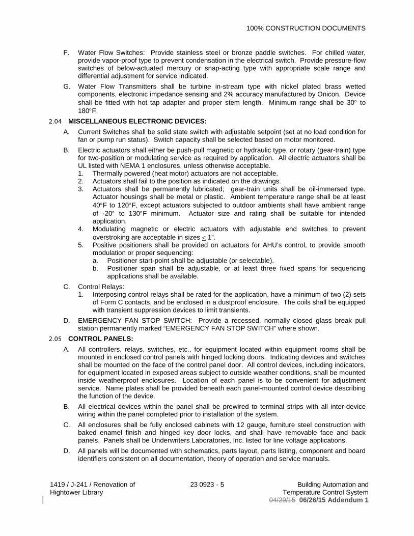
100% CONSTRUCTION DOCUMENTS
1419 / J-241 / Renovation of Hightower Library
23 0923 - 5 Building Automation and Temperature Control System
04/29/15 06/26/15 Addendum 1
F. Water Flow Switches: Provide stainless steel or bronze paddle switches. For chilled water, provide vapor-proof type to prevent condensation in the electrical switch. Provide pressure-flow switches of below-actuated mercury or snap-acting type with appropriate scale range and differential adjustment for service indicated.
G. Water Flow Transmitters shall be turbine in-stream type with nickel plated brass wetted components, electronic impedance sensing and 2% accuracy manufactured by Onicon. Device shall be fitted with hot tap adapter and proper stem length. Minimum range shall be 30 to 180 F.
2.04 MISCELLANEOUS ELECTRONIC DEVICES:A. Current Switches shall be solid state switch with adjustable setpoint (set at no load condition for
fan or pump run status). Switch capacity shall be selected based on motor monitored.B. Electric actuators shall either be push-pull magnetic or hydraulic type, or rotary (gear-train) type
for two-position or modulating service as required by application. All electric actuators shall be UL listed with NEMA 1 enclosures, unless otherwise acceptable.1. Thermally powered (heat motor) actuators are not acceptable.2. Actuators shall fail to the position as indicated on the drawings.3. Actuators shall be permanently lubricated; gear-train units shall be oil-immersed type.
Actuator housings shall be metal or plastic. Ambient temperature range shall be at least 40 F to 120 F, except actuators subjected to outdoor ambients shall have ambient range of -20 to 130 F minimum. Actuator size and rating shall be suitable for intended application.
4. Modulating magnetic or electric actuators with adjustable end switches to prevent overstroking are acceptable in sizes 1”.
5. Positive positioners shall be provided on actuators for AHU’s control, to provide smooth modulation or proper sequencing:a. Positioner start-point shall be adjustable (or selectable).b. Positioner span shall be adjustable, or at least three fixed spans for sequencing
applications shall be available.C. Control Relays:
1. Interposing control relays shall be rated for the application, have a minimum of two (2) sets of Form C contacts, and be enclosed in a dustproof enclosure. The coils shall be equipped with transient suppression devices to limit transients.
D. EMERGENCY FAN STOP SWITCH: Provide a recessed, normally closed glass break pull station permanently marked “EMERGENCY FAN STOP SWITCH” where shown.
2.05 CONTROL PANELS:A. All controllers, relays, switches, etc., for equipment located within equipment rooms shall be
mounted in enclosed control panels with hinged locking doors. Indicating devices and switches shall be mounted on the face of the control panel door. All control devices, including indicators, for equipment located in exposed areas subject to outside weather conditions, shall be mounted inside weatherproof enclosures. Location of each panel is to be convenient for adjustment service. Name plates shall be provided beneath each panel-mounted control device describing the function of the device.
B. All electrical devices within the panel shall be prewired to terminal strips with all inter-device wiring within the panel completed prior to installation of the system.
C. All enclosures shall be fully enclosed cabinets with 12 gauge, furniture steel construction with baked enamel finish and hinged key door locks, and shall have removable face and back panels. Panels shall be Underwriters Laboratories, Inc. listed for line voltage applications.
D. All panels will be documented with schematics, parts layout, parts listing, component and board identifiers consistent on all documentation, theory of operation and service manuals.

100% CONSTRUCTION DOCUMENTS
1419 / J-241 / Renovation of Hightower Library
23 0923 - 6 Building Automation and Temperature Control System
04/29/15 06/26/15 Addendum 1
E. Mount panels adjacent to associated equipment on vibration free walls or free standing steel angle supports.
2.06 GENERAL PRODUCT DESCRIPTION:A. The Building Automation System shall be capable of integrating multiple building functions
including equipment supervision and control, alarm management, energy management, fire management, lighting control, information management, and historical data collection and archiving.
B. In general, new controls equipment and wiring shall be an extension of the existing system, and shall match in type and specification the existing equipment, and shall meet the basic specifications in this section:1. Standalone DDC panels.2. Application specific controllers (ASP’s).3. Remote Display Devices.4. The system shall be modular in nature, and shall permit expansion of both capacity and
functionality through the addition of sensors, actuators, standalone DDC panels, and operator devices.
5. System architectural design shall eliminate dependence upon any single device for alarmreporting and control execution. Each DDC panel shall operate independently by performing its own specified control, alarm management, operator I/O, and historical data collection. The failure of any single component or network connection shall not interrupt the execution of control strategies at other operational devices.
6. Standalone DDC panels shall be able to access any data from, or send control commands and alarm reports directly to any other DDC panel or combination of panels on the network without dependence upon a central processing device, such as a central file server.
2.07 NETWORKING/COMMUNICATIONS (LOCAL NETWORK):The design of the BAS shall be networked. Inherent in the system's design shall be the ability to expand or modify the network via a local network.A. Local Network:
1. Data Access: All operator devices, either network resident or connected via dial-up modems, shall have the ability to access all point status and application report data on the network. Access to system data shall not be restricted by the hardware configuration of the facility management system.
2. Global Data Sharing: Global Data Sharing or Global point broadcasting shall allow point data to be shared between ASCs, when it would be inefficient or impractical to locate multiple sensors.
3. General Network Design: Network design shall include the following provisions:a. Data transfer rates for alarm reporting and quick point status from multiple ASCs. The
minimum baud rate shall be 9600 baud.b. Support of any combination of ASCs. A minimum of 100 ASCs shall be supported on
a single local network. The bus shall be addressable for up to 255 ASCs.c. Detection of single or multiple failures of ASCs or the network media.d. Error detection, correction, and retransmission to guarantee data integrity.e. Commonly available, multiple-sourced, networking components shall be used.f. Use of an industry standard protocol, such as Optomux, and IEEE RS-485
communications interface.2.08 DDC PANELS:
A. General: Digital Panels shall be microprocessor-based, multi-tasking, multi-user, digital control processors.
B. Memory: Each Digital Panel shall have sufficient memory to support its own operating system and data bases including:1. Control processes.
100% CONSTRUCTION DOCUMENTS
1419 / J-241 / Renovation of Hightower Library
23 0923 - 7 Building Automation and Temperature Control System
04/29/15 06/26/15 Addendum 1
2. Energy Management Applications.3. Alarm Management.4. Trend Data.5. Maintenance Support Applications.6. Operator I/O.7. Manual Override Monitoring.
C. Expandability: The system shall be modular in nature, and shall permit easy expansion through the addition of field controllers, sensors, and actuators.
D. Serial Communication Parts: Digital Panels shall provide at least two RS-232C serial data communication ports for simultaneous operation of multiple operator I/O devices, such as laptop computers, Personal Computers, and Video Display terminals.
E. Hardware Override Monitoring: Digital Panels shall monitor the status of all overrides, and include this information in logs and summaries to inform the operator that automatic control has been inhibited.
F. Integrated On-Line Diagnostics: Each Digital Panel shall continuously perform self-diagnostics, communication diagnosis and diagnosis of all subsidiary equipment. Digital Panels shall provide both local and remote annunciation of any detected component failures, or repeated failure to establish communication. Indication of the diagnostic results shall be provided at each Digital Panel.
G. Surge and Transient Protection: Isolation shall be provided at all network terminations, as well as all field point terminations, to suppress induced voltage transients consistent with IEEE Standard 587-1980. Isolation levels shall be sufficiently high as to allow all signal wiring to be run in the same conduit as high voltage wiring where acceptable by electrical code.
H. Powerfail Restart: In the event of the loss of normal power, there shall be an orderly shutdownof the Digital Panel to prevent the loss of data base or operating system software:1. Non-volatile memory shall be incorporated for all critical controller configuration data, and
battery backup shall be provided to support the real-time clock and all volatile memory for a minimum of 72 hours.
2. Upon restoration of normal power, the Digital Panel shall automatically resume full operation without manual intervention.
2.09 SYSTEM SOFTWARE FEATURES:A. General:
1. All necessary software to form a complete operating system, as described in this specification, shall be provided.
2. The software programs specified in this section shall be provided as an integral part of the Digital Panel, and shall not be dependent upon any higher level computer for execution.
B. Control Software Description:1. Equipment Cycling Protection: Control software shall include a provision for limiting the
number of times each piece of equipment may be cycled within any one-hour period.2. Heavy Equipment Delays: The system shall provide protection against excessive demand
situations during start-up periods by automatically introducing time delays between successive start commands to heavy electrical loads.
C. Energy Management Applications: Digital Panels shall have the ability to perform any or all of the following energy management routines:1. Time of Day Scheduling.2. Calendar Based Scheduling.3. Holiday Scheduling.4. Optimal Start.5. Optimal Stop.6. Demand Limiting.
100% CONSTRUCTION DOCUMENTS
1419 / J-241 / Renovation of Hightower Library
23 0923 - 8 Building Automation and Temperature Control System
04/29/15 06/26/15 Addendum 1
7. Load Rolling.8. Heating/Cooling Interlock.
D. All programs shall be executed automatically without the need for operator intervention, and shall be flexible enough to allow user customization. Programs shall be applied to building equipment described in the "Execution" portion of this specification.
E. Programming Capability: Digital Panels shall be able to execute configured processes defined by the user to automatically perform calculations and control routines.
F. Process Inputs and Variables: It shall be possible to use any of the following in a configured process:1. Any system-measured point data or status.2. Any calculated data.3. Any results from other processes.4. Boolean logic operators (and, or).
G. Process Triggers: Configured processes may be triggered based on any combination of the following:1. Time of day.2. Calendar date.3. Other processes.4. Events (e.g., point alarms).
H. Data Access: A single process shall be able to incorporate measured or calculated data from any and all other ASCs. In addition, a single process shall be able to issue commands to points in any and all other ASCs on the local network.
I. Alarm Management: Alarm management shall be provided to monitor, buffer, and direct alarm reports to operator devices and memory files. Each Digital Panel shall perform distributed, independent alarm analysis and filtering to minimize operator interruptions due to non-critical alarms, minimize network traffic, and prevent alarms from being lost. At no time shall the Digital Panel's ability to report alarms be affected by either operator activity at the local I/O device, or communications with other ASCs on the network:
J. Point Change Report Description: All alarm or point change reports shall include the points' English language description, and the time and date of occurrence.
K. Prioritizing: The user shall be able to define the specific system reaction for each point. Alarms shall be prioritized to minimize nuisance reporting and to speed operator response to critical alarms. A minimum of three priority levels shall be provided. Users shall have the ability to manually inhibit alarm reporting for each point. The user shall also be able to define conditions under which point changes need to be acknowledged by an operator, and/or logged for analysis at a later date.
L. Report Routing: Alarm reports and messages shall be directed to an operator device.M. Alarm Messages: In addition to the point's descriptor and the time and date, the user shall be
able to print, display or store a 60-character alarm message to more fully describe the alarm condition or direct operator response. Each Digital Panel shall be capable of storing a library of at least 100 Alarm Messages. Each message may be assignable to any number of points in the panel.
N. Auto-Dial Alarm Management: In Dial-up applications, only critical alarms shall initiate a call to a remote operator device. In all other cases, call activity shall be minimized by time-stamping and saving reports until a manual request is received, or until the buffer space is full. The alarm buffer must store a minimum of 50 alarms.
100% CONSTRUCTION DOCUMENTS
1419 / J-241 / Renovation of Hightower Library
23 0923 - 9 Building Automation and Temperature Control System
04/29/15 06/26/15 Addendum 1
O. Trend Analysis: A data collection utility shall be provided to automatically sample, store, and display system data. Measured and calculated analog and binary data shall be assignable to user-definable trends for the purpose of collecting operator-specified performance data over extended periods of time. Sample intervals of 1 minute to 24 hours, in one-minute or one-hour intervals, shall be provided. Each Digital Panel shall have a dedicated buffer for tend data, and shall be capable of storing 16 trend logs. Each trend log shall have up to four points trended at48 data samples each. Data shall be sorted at the Digital Panel, and uploaded to floppy disk storage when archival is desired.
P. Runtime Totalization: Digital Panels shall automatically accumulate and store runtime hours for binary input and output points specified in the "Execution" portion of this specification.1. The Totalization routine shall have a sampling resolution of one minute.2. The user shall have the ability to define a warning limit for Runtime Totalization. Unique,
user-specified messages shall be generated when the limit is reached.Q. Pulse Totalization: Digital Panels shall automatically sample, calculate and store consumption
totals on a daily, weekly, or monthly basis for user-selected analog and binary pulse input-type points:1. Totalization shall provide calculation and storage accumulations of up to 9,999,999 units
(e.g. KWH, gallons, KBtu, tons, etc.).2. The Totalization routine shall have a sampling resolution of one minute.3. The user shall have the ability to define a warning limit. Unique, user-specified messages
shall be generated when the limit is reached.4. The information available from the Pulse Totalization shall include, but not be limited to, the
following:a. Peak Demand, with date and time stamp.b. 24-hour Demand Log.c. Accumulated KWH for day.d. Sunday through Saturday KWH usage.e. Sunday through Saturday Demand KW.f. Demand KW annual history for past 12 periods.g. KWH annual history for past 12 periods.
R. Event Totalization: Digital Panels shall have the ability to count events, such as the number of times a pump or fan system is cycled on and off:1. The Event Totalization feature shall be able to store the records associated with a
minimum of 9,999,999 events before reset.2. The user shall have the ability to define a warning limit. Unique, user-specified messages
shall be generated when the limit is reached. 2.10 APPLICATION SPECIFIC CONTROLLERS:
A. Each Digital Panel shall be able to extend its monitoring and control through the use of standalone Application Specific Controllers (ASCs).
B. Each ASC shall operate as a standalone controller capable of performing its specified control responsibilities independently of other controllers in the network. Each ASC shall be a microprocessor-based, multi-tasking, real-time digital control processor.
C. Each ASC shall have sufficient memory to support its own operating system and databases including:1. Control Processes.2. Energy Management Applications.3. Operator I/O (Portable Service Terminal).
D. The operator interface to any ASC point data or programs shall be through the Digital Panel or portable operator's terminal connected to any ASC on the network.
100% CONSTRUCTION DOCUMENTS
1419 / J-241 / Renovation of Hightower Library
23 0923 - 10 Building Automation and Temperature Control System
04/29/15 06/26/15 Addendum 1
E. ASCs shall directly support the temporary use of a portable service terminal that can be connected to the ASC via zone temperature or directly at the controller. The capabilities of the portable service terminal that can be connected to the ASC via zone temperature or directly at the controller. The capabilities of the portable service terminal shall include, but not be limited to, the following:1. Display temperatures.2. Display status.3. Display setpoints.4. Display control parameters.5. Override binary output control.6. Override analog setpoints.7. Modification of gain and offset constants.
F. Powerfail Protection: All system setpoints, proportional bands, control algorithms, and any other programmable parameters shall be stored such that a power failure of any duration does not necessitate reprogramming the ASC.
G. Application Descriptions:1. VAV Terminal Controllers:
a. VAV Terminal Unit Controllers shall support, but not be limited to, the control of the following configurations of VAV boxes to address current requirements described in the "Execution" portion of this specification, and for future expansion:(1) Single Duct Only (Cooling Only, or Cooling with Reheat.(2) Fan Powered (Parallel/Side Pocket, Series/On-Off Logic, Series/Proportional
Fan).b. VAV Terminal Unit Controllers shall support the following types of point inputs and
outputs:(1) Proportional Cooling Outputs.(2) Box and Baseboard Heating Outputs (Proportional, or 1 to 3 Stages).(3) Fan Control Output (On/Off Logic, or Proportional Series Fan Logic)
c. VAV Terminal Unit Controllers shall support the following library of control strategies to address the requirements of the sequences described in the "Execution" portion of this specification, and for future expansion:(1) Daily Schedules.(2) Lighting Logic Interlock.(3) Temporary Override Mode.
2. Temporary Override Modes: Temporary Occupancy Mode: The controller interface to the zone temperature sensor shall allow for an optional momentary switch to change the modeof the controller optionally interlock the room lights for a preset amount of time.
3. Alarm Management: Each VAV Terminal Unit Controller shall perform its own limit and status monitoring and analysis to maximize network performance by reducing unnecessarycommunications.
2.11 FRONT END GRAPHICS:A. The BAS contractor shall provide all the necessary hardware, data, information, and graphical
images for the DDC system to publish fully interactive web-page graphics for monitoring and operating the DDC system's controllers using only a standard web browser. Support for both Microsoft Internet Explorer and Netscape Navigator must be provided.
100% CONSTRUCTION DOCUMENTS
1419 / J-241 / Renovation of Hightower Library
23 0923 - 11 Building Automation and Temperature Control System
04/29/15 06/26/15 Addendum 1
B. The contractor shall include developed graphics for each piece of equipment being controlled and/or monitored by the BAS. BAS graphics will include the following screen pages as a minimum, but not limited to:1. System Pages:
a. Initial Screen. Provide building address and links to system screens on a scanned-in background of the building front elevation. Elevation will be from an architectural rendering or photograph. Links will be provided to each floor plan and as applicable, each mechanical chiller plant, electrical monitoring system and fuel monitoring systems.
b. Building floor plan layouts will show every room. Where temperature and humidity sensors are installed in the building, show readings on the floor plan. Show all equipment including chillers, AHUs, PIUs, VAVs, generators, etc. Provide links to each piece of equipment and to system pages.
c. Hot Water heating plant will default to the hot water heating system loop. Show each boiler and hot water heating pump with double lined water piping. Show all water temperatures and flows, basic chiller operating points and equipment status. Layout of the hot water heating plant will resemble the equipment layout in the building.
2. Equipment Pages:a. VAV Boxes: Provide a floor plan showing the VAV box and the area the box serves.
Show all sensing points on the page at the unit.PART 3 EXECUTION3.01 WIRING:
A. All electrical wire, conduit, cable, fittings, junction boxes, connectors, etc., associated with the systems, including interlock wiring, shall be furnished and installed complete under these specifications.
B. Installation shall be in accordance with the requirements of Division 26, the National Electrical Code and local codes. All electrical work included under this section shall be complete with labor, materials and installations.
C. Run all wiring and conduit concealed unless conditions do not allow. Secure approval from Engineer prior to installing surface raceway. Where surface raceway is required, it shall be wire mold or approved equal.
D. All control wiring routed in conduit shall not have any other type of wiring (power, etc.) routed in the same conduit.
E. Where required for electronic controls or interfacing, provide relays and other devices with low impedance contacts. Where required to maintain proper relay operation and prevent chatter, increase minimum control wire gauges specified herein.
F. All line voltage electrical wiring shall be enclosed in conduit. All exposed low voltage electrical wiring shall be installed in conduit or EMT. All low voltage wiring located above ceilings in plenums shall be 25/50 flame spread/smoke developed rated and U.L. listed. Support wiring 24” OC by clips to structure.
G. For control systems, all wiring will be manufactured by Beldon or equal. Cabling for pulse demand meter shall be as manufactured by Beldon or equal. Provide cable in accordance with manufacturer’s recommendations.
3.02 INSTALLATION REQUIREMENTS:A. Any panels associated with the control system shall be furnished and installed under this
section of the work. Connected to numbered terminal strips shall terminate panel wiring. Wire nut connections shall not be allowed.
100% CONSTRUCTION DOCUMENTS
1419 / J-241 / Renovation of Hightower Library
23 0923 - 12 Building Automation and Temperature Control System
04/29/15 06/26/15 Addendum 1
B. All devices, panels, etc. furnished and/or installed shall be located where they can be calibrated and maintained from the floor without use of a ladder. These items shall be identified by means of plates made of plastic, suitably engraved, embossed or punched.
C. Any conduit on roof shall be at an absolute minimum and shall have prior written approval.D. All conduit and fittings used indoors and outdoors shall be metal to minimize corrosion and
moisture entry.3.03 LOCATING DDC PANELS:
A. In order to minimize wiring costs, DDC panels should be installed near equipment or systems, which are to be monitored and/or controlled. Panels located in administrative, common areas, or equipment aisles will be recessed mounted. Panels mounted in electrical or mechanical rooms will be surface mounted.
B. Consider providing sub-unit controllers or I/O expansion units near each cluster of sensor/actuator points, with sub-unit controllers and I/O expansion units reporting to the stand-alone controllers. Where practical, Application Specific Controllers or stand-alone controllers should be installed in mechanical equipment rooms.
C. All PC boards enclosed in metal boxes shall be mounted to a non-conductive, non-metallic surface to avoid shorting or grounding.
3.04 POWER/ENVIRONMENT/SPACE REQUIREMENTS:A. The environmental conditions in the space in which the stand-alone controllers and associated
equipment are located shall meet the manufacturer’s requirements of 30 F to 120 F and 5% RH to 95% RH.
B. Provide adequate space in front of the equipment for easy access and repairs. Provide adequate lighting over all DDC equipment and panels enclosing interfacing devices.
3.05 OPERATOR INSTRUCTION AND TRAINING:A. During system commissioning and at such time as acceptable performance of the system
hardware and software has been established, the BAS contractor shall provide on-site operator instruction to the Owner’s operating personnel. Operator instruction during normal working hours shall be performed by a competent BAS contractor representative familiar with the system’s BAS software, hardware and accessories.
B. At a time mutually agreed upon during system commissioning as stated above, BAS contractor shall give 4 hours of instructions to the Owner’s designated personnel on the operation of all central processing and peripherals and describe intended use with respect to the programmed functions specified. Operator orientation of the FMS shall include, but not be limited to, the overall operational program, equipment functions (both individually and as part of the total integrated system), commands, advisories, and appropriate operator intervention required in responding to the system’s operation. An Owner’s Manual, prepared for this project by the BAS contractor, shall be used in addition to the instruction. Two (2) copies of the Owner’s Manualshall be provided.
END OF SECTION
Related Documents