PRESENTATION ON CAMLESS ENGINE .

1388514083camless Engine
Dec 12, 2015
CamLess Engines
Welcome message from author
This document is posted to help you gain knowledge. Please leave a comment to let me know what you think about it! Share it to your friends and learn new things together.
Transcript

PRESENTATION ONCAMLESS ENGINE .

CONTENTS :-
1. INTRODUCTION.2. WORKING OF PUSH ROD ENGINE . > CAM SHAFT .
> CRANK SHAFT .
> WORKING .
3. CAMLESS ENGINE .4. OBJECTIVES OF CAMLESS ENGINE .5. CAMLESS ENGINE WORKING .6. OVERVIEWS OF CAMLESS .7. CAMLESS VALVE TRAIN . 8. CAMLESS ENGINE TECHNOLOGY .9. COMPONENTS OF CAMLESS ENGINE .10. USE OF CAMLESS ENGINE .11. ADVANTAGES & DISADVANTAGES .12. CURRENT APPLICATIONS .13. DISCUSSION & CONCLUSION .
INTRODUCTION
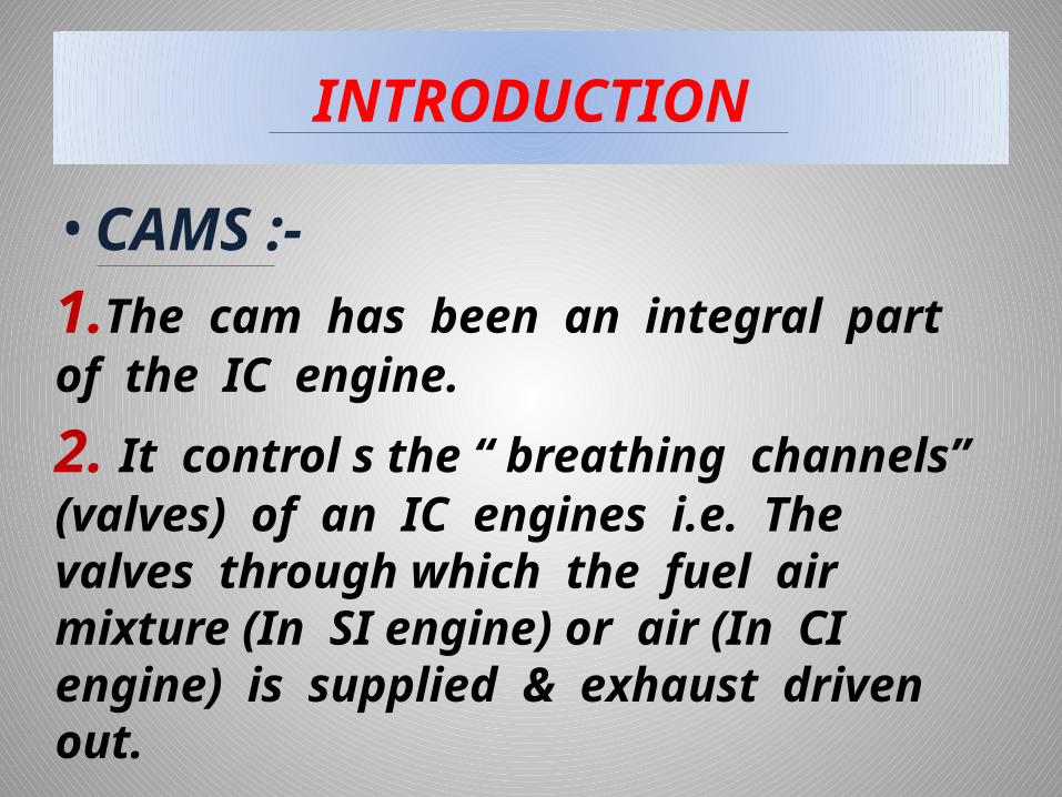
• CAMS :-1.The cam has been an integral part of the IC engine.
2. It control s the “ breathing channels” (valves) of an IC engines i.e. The valves through which the fuel air mixture (In SI engine) or air (In CI engine) is supplied & exhaust driven out.

CAM SHAFT
The camshaft provides a means of actuating the opening and controlling the period before closing, both for the inlet as well as the exhaust valves.
It also provides a drive for the ignition distributor and the mechanical fuel pump.

WORKING When the crank shaft turn the cam shaft the cam
lobs come up under the valve lifter and cause the lifter to move upwards. The upward push is carried by the pushrods through the rocker arm. The rocker arm is pushed by the pushrod, the other end moves down. This pushes down on the valve stem and cause it to move down thus opening the port.
When the cam lobe moves out from under the valve lifter, the valve spring pulls the valve back upon its seat. At the same time stem pushes up on the rocker arm, forcing it to rock back. This pushes the push rods and the valve lifter down, thus closing the valve.
The timing of the engine is dependent on the shape of the cam lobes and the rotational velocity of the camshaft .
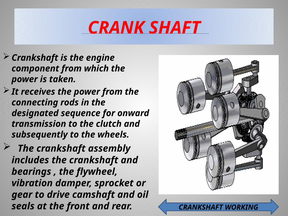
CRANK SHAFT Crankshaft is the engine
component from which the power is taken.
It receives the power from the connecting rods in the designated sequence for onward transmission to the clutch and subsequently to the wheels.
The crankshaft assembly includes the crankshaft and bearings , the flywheel, vibration damper, sprocket or gear to drive camshaft and oil seals at the front and rear. CRANKSHAFT WORKING
WORKING OF PUSH ROD ENGINE
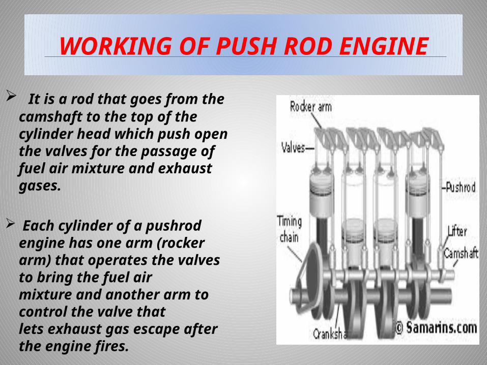
It is a rod that goes from the camshaft to the top of the cylinder head which push open the valves for the passage of fuel air mixture and exhaust gases.
Each cylinder of a pushrod engine has one arm (rocker arm) that operates the valves to bring the fuel air mixture and another arm to control the valve that lets exhaust gas escape after the engine fires.
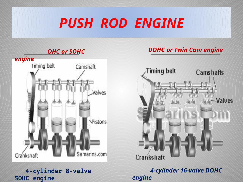
PUSH ROD ENGINE
OHC or SOHC engine DOHC or Twin Cam engine
4-cylinder 8-valve SOHC engine 4-cylinder 16-valve DOHC engine
CAM IN A CONVENTIONAL IC ENGINE
DISADVANTAGES :-> Less volumetric efficiency , improper combustion & ultimately detonation in SI engine.
> Reduction in output of the engine.> Valve timing diagram at slow speed & high speed are different , which reduces flexibility of engine .> Cam design need to compromise between maximum efficiency & power .

CAM LESS ENGINE
DEFINATION:- In a cam less engine ,electromechanical
actuators (a set of electromagnets) , placed directly on the valve , replace the camshaft .
This technology makes it possible “ to optimise the circulation of gases in the engines , both for intake & exhaust .
It gives the valves great flexibility in opening & closing , improve fuel consumption , clean exhaust technology & performance .
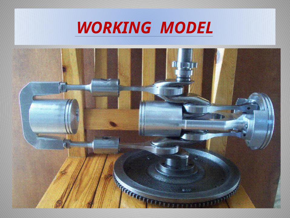
WORKING MODEL
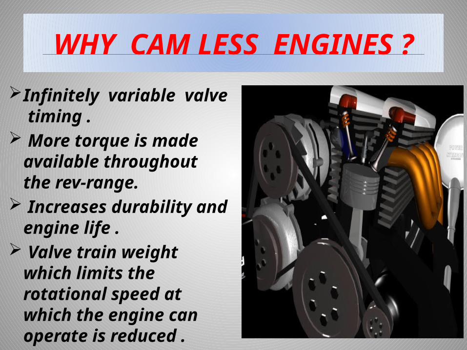
WHY CAM LESS ENGINES ?
Infinitely variable valve timing .
More torque is made available throughout the rev-range.
Increases durability and engine life .
Valve train weight which limits the rotational speed at which the engine can operate is reduced .

OBJECTIVES OF CAM LESS ENGINE
Increased efficiency .
Reduced emissions .
Improved power over existing internal combustion engines .

HOW CAMLESS ENGINE WORKS
INTAKE :- The intake phase of the cycle starts when
the tip of the rotor passes the intake port. At the moment when the intake port is
exposed to the chamber, the volume of that chamber is close to its minimum.
As the rotor moves past the intake port, the volume of the chamber expands, drawing air/fuel mixture into the chamber.
When the peak of the rotor passes the intake port, that chamber is sealed off and compression begins.

Combustion :-Most rotary engines have two spark plugs.
The combustion chamber is long, so the flame would spread too slowly if there were only one plug.
When the spark plugs ignite the air/fuel mixture, pressure quickly builds, forcing the rotor to move.
The pressure of combustion forces the rotor to move in the direction that makes the chamber grow in volume.
The combustion gases continue to expand, moving the rotor and creating power, until the peak of the rotor passes the exhaust port.

Exhaust :-Once the peak of the rotor passes the
exhaust port, the high-pressure combustion gases are free to flow out the exhaust.
As the rotor continues to move, the chamber starts to contract, forcing the remaining exhaust out of the port.
By the time the volume of the chamber is nearing its minimum, the peak of the rotor passes the intake port and the whole cycle starts again.

CAMLESS ENGINE
OVER VIEW:- To eliminate the cam , camshaft &
other connected mechanisms , the cam less engine makes use of three vital components, the sensors , ECU (electronic control unit) & actuator .
component
sensors
ELECTRONIC CONTROL
UNIT ACTUATOR

OVER VIEW
The sensor will send signals to ECU .
Electronic control unit (ECU) :-
> consists of a microprocessor , which is provided with a software algorithm .
> The microprocessor issues signals to the solid-state circuitry based on the algorithm .
> This signals controls the actuator .
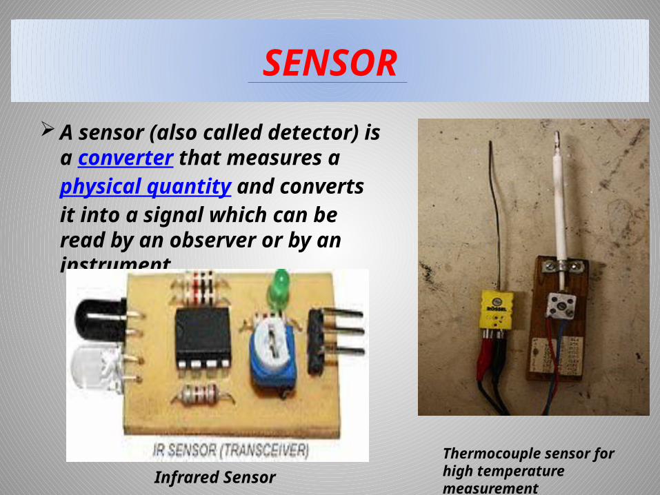
SENSOR
A sensor (also called detector) is a converter that measures a physical quantity and converts it into a signal which can be read by an observer or by an instrument.
Thermocouple sensor for high temperature measurement Infrared
Sensor

ELECTRONIC CONTROL UNIT
The modern engines are controlled by computers which are called ECU or EMS .
The ECU is located inside the vehicle. It receives signals from the sensors in the circuit and controls the brake pressure at the road wheels according to the data analyzed by the Unit .
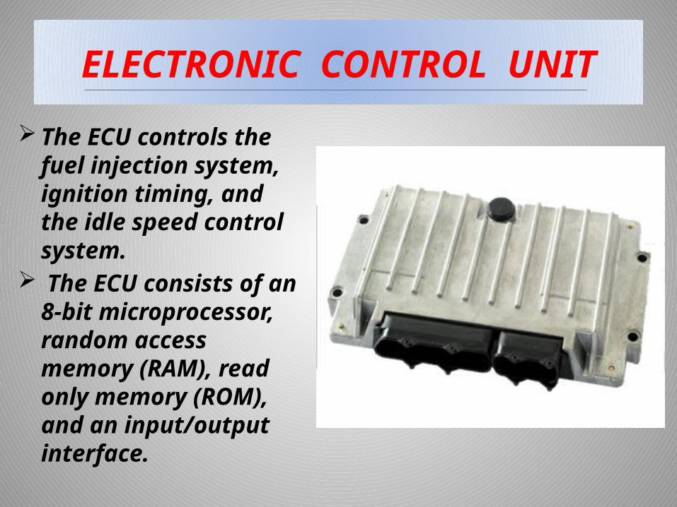
ELECTRONIC CONTROL UNIT
The ECU controls the fuel injection system, ignition timing, and the idle speed control system.
The ECU consists of an 8-bit microprocessor, random access memory (RAM), read only memory (ROM), and an input/output interface.
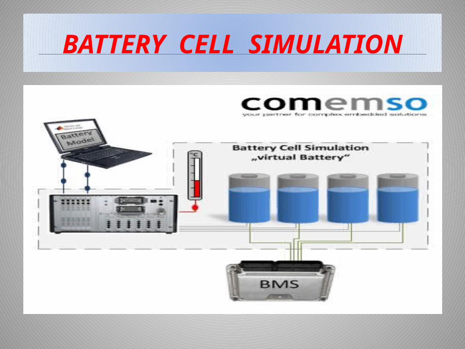
BATTERY CELL SIMULATION

BLOCK DIAGRAM OF ECU
CHARACTERISTIC OF ECU
The air-fuel ratio of engine is controlled with closed loop; therefore the exhaust emission is clean.
It has idle speed control function, so the idle working condition is more stable.
It can dynamically control the engine's spark advance angle and dwell angle, so the mixed gas burns completely.
It can cut off the fuel when coasting with gear, therefore is cheaper as fuel consumption.
It has air conditioning system control function.
ENGINE MANAGEMENT SYSTEM
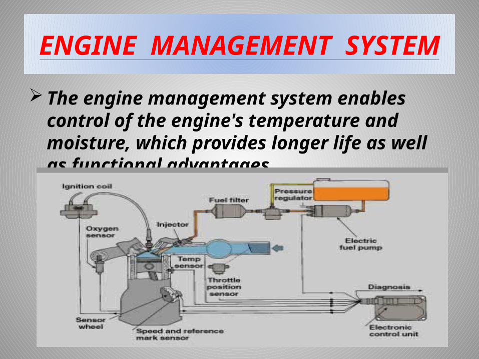
The engine management system enables control of the engine's temperature and moisture, which provides longer life as well as functional advantages.

POWER BOOSTER & MASTER CLYINDER ASSEMBLY
The power booster and master cylinder assembly is mounted on the firewall and is activated when the driver pushes down on the brake pedal. It provides the power assistance required during braking.

ACTUATOR
An actuator is a type of motor for moving or controlling a mechanism or system.
It is operated by a source of energy, usually in the form of an electric current, hydraulic fluid pressure or pneumatic pressure, and converts that energy into some kind of motion.
WORKING PRINCIPLE
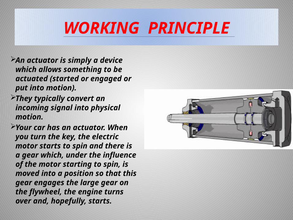
An actuator is simply a device which allows something to be actuated (started or engaged or put into motion).
They typically convert an incoming signal into physical motion.
Your car has an actuator. When you turn the key, the electric motor starts to spin and there is a gear which, under the influence of the motor starting to spin, is moved into a position so that this gear engages the large gear on the flywheel, the engine turns over and, hopefully, starts.
Cam less valve train
In the cam less valve train, the valve motion is controlled directly by a valve actuator – there is no camshaft or connecting mechanisms.
Electrohydraulic cam less valve train controls the valve operations, opening, closing etc.
The electrohydraulic valve actuator works by sending pressurised hydraulic fluid to the engine valve to move it open or closed.

ELETROMECHANICAL VALVE ACTUATORS
Electromechanical actuators control valve motion by electromagnetic forces developed by coils surrounding the valve stem.
When the holding current in the upper coil goes to zero, the valve starts to open under spring action.
Current starts flowing in the lower coil until it reaches the holding value to hold the valve open at desired lift.
This process is reversed to close the valve.

Cam less Valve Actuation
Cam less valve actuation expands upon the concept of variable valve timing and lift by completely eliminating the camshaft and mechanical valve actuation mechanism from the cylinder head.
In place of the camshaft mechanism, valve motion is actuated and controlled through either electrical energy or hydraulic energy. This can occur over a wide range of engine operating conditions.

CAMLESS ENGINE VALVE ACTUATION SYSTEM FOR FUEL
EFFICIENCY IMPROVEMENT
WHAT:- - Improve the fuel efficiency of IC
engines significantly (10-50%) .
- Through the independent control of valve opening & closing time for a wide range of engine operation condition .
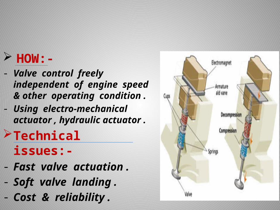
HOW:-- Valve control freely
independent of engine speed & other operating condition .
- Using electro-mechanical actuator , hydraulic actuator .
Technical issues:-- Fast valve actuation .- Soft valve landing .- Cost & reliability .

Types of cam less engines
Using Hydraulic actuators .
using Pneumatic actuators .
using Solenoid control actuators . using Electro-hydraulic (using
piezoelectric) actuators .
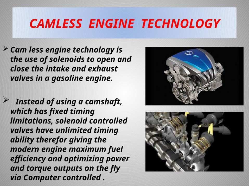
CAMLESS ENGINE TECHNOLOGY
Cam less engine technology is the use of solenoids to open and close the intake and exhaust valves in a gasoline engine.
Instead of using a camshaft, which has fixed timing limitations, solenoid controlled valves have unlimited timing ability therefor giving the modern engine maximum fuel efficiency and optimizing power and torque outputs on the fly via Computer controlled .

DESIGN APPROACH FOR CAMLESS ENGINE
The cam less engine was created on the basis of an existing four-cylinder, four-valve engine.
The original cylinder head with all the valves, springs, camshafts, etc. was replaced by a new cylinder head assembly fully integrated with the cam less valve train.
The camshaft drive was eliminated, and a belt-driven hydraulic pump was added.
There was no need for lubrication, and the access for engine oil from the engine block to the cylinder head was closed off.

COMPONENTS OF CAMLESS ENGINE
Main components of a cam less engine are:-
Engine valve .
Solenoid valve .
high pressure pump .
low pressure pump .
cool down accumulator .

ENGINE VALVE
The valve piston is attached to the top of the valve, and both the valve and the piston can slide inside a sleeve.
The sleeve openings above and below the valve piston allow the hydraulic fluid to enter and exit .
A seal in the lower part of the sleeve prevents leakage of fluid into the intake or exhaust port .
There is a tight hydraulic clearance between the valve and the sleeve .
The clearance between the sleeve and the cylinder head is relatively large, which improves the centering of the valve in its seat Circulation of hydraulic fluid through the chambers above and below the valve piston cools and lubricates the valve .
Absence of side forces reduces stresses, friction and wear.

ASSEMBLY OF ENGINE VALVE
cross section of the engine valve assembly

SOLENOID VALVE
The solenoid has conically shaped magnetic poles .
This reduces the air gap at a given stroke .
A strong spring is needed to obtain quick closing time and low leakage between activations .
The hydraulic energy loss is the greatest during the closing of either the high- or the low-pressure solenoid, because it occurs during the highest piston velocity .
Both high-pressure and low-pressure solenoid valves are of the same design .

HYDRAULIC SYSTEM
An engine-driven variable-displacement pump automatically adjusts its output to maintain the required pressure.
The high-pressure and the low-pressure reservoirs are connected to all corresponding locations serving the high- and the low-pressure solenoids and the check valves . diagram of the hydraulic system

HIGH PRESSURE PUMP
The pump has a single eccentric-driven plunger and a single normally-open solenoid valve.
During each down stroke of the plunger the solenoid valve is open, and the plunger barrel is filled with hydraulic fluid from the low pressure branch of the system.
During the upstroke of the plunger, the fluid is pushed back into the low pressure branch, as long as the solenoid valve remains open.
Closing the solenoid valve causes the plunger to pump the fluid through a check valve into the high pressure branch of the system.
Varying the duration of the solenoid voltage pulse varies the quantity of the high-pressure fluid delivered by the pump during each revolution.

LOW PRESSURE PUMP
A small electrically driven pump picks up oil from the sump and delivers it to the inlet of the main pump.
Only a small quantity of oil is required to compensate for the leakage through the leak-off passage, and to assure an adequate inlet pressure for the main pump.
Any excess oil pumped by the small pump returns to the sump through a low-pressure regulator.
A check valve 1 assures that the inlet to the main pump is not subjected to pressure fluctuations that occur in the low-pressure reservoir.

USE OF THE CAMLESS ENGINE
These are huge 2 stroke Diesel engines with power rating more than 100,000 KW.
These engines are running with computer hardware, controlling both fuel exhaust valve operation and the Cylinder Lubrication.
Camless Engines are made by MAN,
B&W, Mitsubishi and New Sulzer.
ADVANTAGES
Independent control of all aspects of valve motion, valve lift, valve open duration etc .
Freedom to optimize all parameters of valve motion based on driving condition .
Reduced engine size and weight . Better fuel economy :- 7 to 10 %
increase . Higher torque & power :- 10 to 15 %
increase . Improved idle stability . Better breathing at low engine speeds . Lower exhaust emissions .

DISADVANTAGES
> Opening & closing of valves requires some power- Electromechanical- alternator Electrohydraulic- accumulator .
Sophisticated electronic control required for gentle seating of valves .
Current solenoids cannot run at high rpms .
Hidden cost of microprocessor & software controls

CURRENT APPLICATIONS
Cam less valve trains using solenoids or magnetic systems are being investigated by BMW and Fiat .
Used in the new Fiat 500 .

DISCUSSION & CONCLUSION
DISCUSSION :-> Although the problem of the power loss, friction , torque & maximum power may be tackled using cam less engines, there are also some problems which arises due to the use of the cam less engines .The use of hydraulic actuators lead to the
slowness due to the inertia of the fluid flow. The use of the pneumatic actuators lead to the use of the high air pressure system .
The use of electromagnetic, piezoelectric and solenoid control actuators need electrical power supply.
DISCUSSION & CONCLUSION
CONCLUSION :-Employs the hydraulic pendulum principle,
which contributes to low hydraulic energy consumption .
The electro hydraulic valve train is integral with the cylinder head, which lowers the head height and improves the engine packaging .
Substantial improvements in performance, fuel economy, and emissions over and above what is achievable in engines with camshaft-based valve trains .
Further research and development are needed to take full advantage of this system .
Related Documents