__________________________________________________________ Guidelines For design of concrete and reinforced concrete structures made of heavy-weight and light-weight concrete without reinforcement prestress (Addition to SNiP 2.03.01-84) __________________________________________________________________ Moscow Central Project Institute of Standard Designs 1989

Welcome message from author
This document is posted to help you gain knowledge. Please leave a comment to let me know what you think about it! Share it to your friends and learn new things together.
Transcript

__________________________________________________________
Guidelines
For design of concrete and reinforced concrete structures made of heavy-weight and light-weight concrete without
reinforcement prestress
(Addition to SNiP 2.03.01-84)
__________________________________________________________________
Moscow Central Project Institute of Standard Designs
1989

2
1. GENERAL RECOMMENDATIONS
Basic Positions
Recommendations of the present Guidelines are applied to design of concrete and reinforced concrete structures produced without reinforcement priestess made of heavy-weight, fine and light-weight concrete and used by temperature no more than 50 Celsius degree above zero and no less than 70 Celsius degree below zero.
Notes: 1. Recommendations of the Guidelines are not applied to design of concrete and reinforced concrete structures for water development facilities, bridges, transport tunnels, pipes under filling dams, highways and aerodromes covering. 2. Definitions “heavy-weight concrete”, “fine concrete” and “light-weight concrete” are used in accordance with GOST 25192-82.
Light-weight concretes may have compact and porous structure that’s why in the present Guidelines there are used definitions “light-weight concrete” for light-weight concrete of compact structure and “porous concrete” for light-weight concrete of porous structure with inter-granular openings more than 6 percent.
Types of light-weight and porous concretes as well as their application fields are given in Annex 1.
Concrete and reinforced concrete members of buildings and structures for corrosive
atmosphere and high humidity conditions should be designed considering requirements of SNiP 1.03.11-85.
(1.4) Prefabricated members structures must conform to requirements of mechanized
production at specialized plants. It is wise to enlarge elements of prefabricated structures as big as it is possible according to weight-lift ability of installing mechanisms, producing and transportation conditions.
(1.5) For monolithic structures it is necessary to use dimensions applicable for inventory
form work as well as enlarged three-dimensional reinforcement cages.
(1.6) It is necessary to pay more attention to rigidity and working life of connections.
Joints and connection structures of members must provide reliable transferring of forces, durability of members in connection zones as well as connection of additional concrete in joints with concrete of structure by means of different structural and technological measures.
(1.7) Concrete members are used:
a) in structures being pressed by little eccentricities of longitudinal forces, not exceeding the values given in Item 3.4;
b) in specific cases in structures being pressed by larger eccentricities as well as in bending structures if their failure does note constitute a danger for human life and equipment safety (members base on solid base etc).
Note: Structures are considered as concrete ones if their durability during the use period is provided only by concrete

3
(1.8) Design winter temperature of outside air is taken as average air temperature of the coldest five-days week depending on the construction region according to SNiP 2.01.01-82. Design technological temperatures are settled in the project statement.
Environment air humidity is determined as average relative humidity of outside air of the hottest month according to the construction region in compliance with SNiP 2.01.01-82 or as relative air humidity of rooms of heated buildings.
Numerical values of given in the present document concrete and reinforcement design characteristics, limit values of crack openings and deflections are used only during design. For construction quality estimation it is necessary to follow the requirements of correspondent state standards and technical specifications.
Basic Calculation Requirements
(1.10) Concrete and reinforced concrete structures must meet the requirements of the load-carrying capacity calculation (first class limit states) and according to serviceability limit state (second class limit states). a) Calculation according to the first class limit states must protect structures against:
- Unstable, elastic or other failure (rigidity calculation considering deflection of the structure before failure);
- Structure stable form failure or position failure. - Endurance rupture (endurance limit calculation of the structure which is under
effect of repeated load – moving and pulsating); - Failures under influence of stresses and adverse environmental impacts (periodic
or permanent aggressive influences, freezing and melting etc);
b) Calculation according to the first class limit states must protect structures against: - Exceeding crack opening (calculation of the crack opening); - Exceeding displacements – deflections, rotation angles, vibration (deformation
calculation).
It is possible not to make calculation of concrete structures according to second class limit states as well as regarding the endurance limit. Notes: 1. Calculations of repeated loads are made in compliance with the recommendations of “Guidelines for design of prestressed reinforced concrete structures made of heavy-weight and light-weight concrete” (Moscow, 1986). 2. Calculations of the form stability or position stability as well as calculations of influence of stresses and adverse environmental impacts are made according to normative documents or Guidelines.
(1.11) Design to limit state of the structure in general as well as of members of structure must be made as a rule for all stages – manufacturing, transportation, installing and use; at the same time design schemes must meet the accepted construction solutions.
(1.12) Loads and effects values, values of safety factors as regards the load fγ , combinations
coefficients as well as dividing of loads into dead loads and live loads must be taken according to requirements of SNiP 2.01.07-85.
Loads values must be multiplied by safety factors as regards the purpose taken according to “Registration rules of responsibility degree of buildings and structures during design” approved by Gosstroy of the USSR.

4
Loads considered during calculations of first class limit states (exploitative) must be taken according to Items 1.15 and 1.17. At the same time to long-term loads belong also a part of total value of short-term loads settled in SNiP 2.01.07-85 and short-term load inserted into the calculation must be taken as reduced by the value considered in long-term load (for example if snow load for the IIIrd region is s = 1000 H/m2 so snow long-term load will be
30010003.0 =×=s H/m2 and snow short-term load 7003001000 =−=s H/m2).
Combinations coefficients belong to total value of short-term loads. It is necessary to consider temperature climatic effects for structures not protected against solar irradiation for climatic sub-regions IVA according to SNiP 2.01.01-82.
(1.13) During calculation of members of prefabricated structures as regards the forces growing during their lifting, transportation and installation it is necessary to insert the load of the member weight with dynamic factor equal to: 1.60 – during transportation 1.40 – during lifting and installing
In this case it is also necessary to consider the load safety factor.
(1.15) Forces in statically indefinable reinforced concrete structures caused by loads and forced displacements (as result of changes of temperature, concrete moisture, supports displacements etc) as well as forces in statically indefinable reinforced concrete structures during their calculation as regards the deformation scheme must be determined considering inelastic concrete and reinforcement deformations and cracks presence.
It is possible to determine forces in statically indefinable reinforced concrete structures on the basis of their linear elasticity for structures whose calculation methods considering inelastic characteristics of reinforced concrete are not worked out as well as for intermediate stage of the calculation considering inelastic characteristics.
(1.16) Width of long-lived and short-lived crack openings for members used in non-aggressive conditions must not exceed values mentioned in Table 1.
Members mentioned in Position 1a of Table 1 can be designed without prestressing only by special justification Table 1 (1, 2)
Limit width of crack opening, mm Work conditions of the structure
Short-lived acrc1 Long-lived acrc2
1. members carrying the load of liquids or gases if the section is a) fully stretched b) partly compressed
2. members carrying the load of granular materials 3. members used in the ground with variable ground-
water elevations 4. other members
0.2 0.3 0.3 0.3
0.4
0.1 0.2 0.2 0.2
0.3

5
Note. By short-lived crack opening we shall basically understand opening under effect of dead loads, long-term and short-term loads; by long-lived crack opening we shall understand – only under effect of dead loads and long-term loads. At the same time safety factor is equal to 1.
(1.19) For under-reinforced concrete members whose load-carrying capacity becomes exhausted concurrent with crack opening in the stretched concrete zone, sectional area of longitudinal stretched reinforcement must be increased by no less than 15 percent in comparison with calculations requirements.
Such increase is to be fulfilled upon the following condition
ucrc MM ≥ ,
where crcM is crack opening moment determined according to Item 4.2 replacing value
serbtR , by serbtR ,2.1 ;
uM is moment corresponding to load-carrying capacity exhaust and determined
according to Items 3.15-3.80; for eccentric compressed and stretched members values are determined relating to the axis going through core point the most distant from the stretched zone (see Item 4.2).
This requirement can be applied to elements which rest on a solid base.
(1.20) Deflections of members of reinforced concrete structures must not exceed limit values
settled considering the following requirements:
a) technological requirements (normal running conditions of cranes, process units, machines, etc);
b) structural requirements (neighbor elements influence; given grade of slope, etc); c) esthetic requirements (a person’s impression of structure workability).
Deflection limits values are given in Table 2.
Deformation calculation must be made by technological or constructive requirements as regards dead loads, short-term and long-term loads; by esthetic loads as regards dead
loads and long-term loads. At the same time it is taken 0.1=fγ
By dead loads, short-term and long-term loads beams and slabs deflections must not exceed 1/150 of a span and 1/75 of an overhanging length in all cases.
Limit deflections values can be increased by the height of a camber if it is not restricted by technological or constructive requirements.
If in the lower room with plain ceiling there are partition walls (not supporting) located across the span of member l and if the distance between these partition walls is lp so the deflection of the member within the distance lp (counted from the line connecting top points of partition walls axes) can be taken up to 1/200lp, at the same time limit deflection must be no more than 1/500l.

6
Table 2 (4)
Structure members Deflection limits
1. Crane beams
For manually operated cranes For electric cranes
500
l
600
l
2. Floors with a plane ceiling and roof members (except the ones mentioned in position 4) if the span is:
l < 6
6 ≤ l ≤ 7.5
l > 7.5
200
l
3 cm
250
l
3. Floors with ribbed ceiling and stairs members if the span is:
l < 5
5 ≤ l ≤ 10
l > 10
200
l
2.5 cm
400
l
4. Roof elements of agricultural building for production purpose if the span is:
l < 6
6 ≤ l ≤ 10
l > 10
150
l
4 cm
250
l
5. Suspended wall panels if the span is:
l < 6
6 ≤ l ≤ 7.5
l > 7.5
200
l
3 cm
250
l
Symbols: l is beams or slabs span; for consoles it is necessary to take l equal to double overhanging length.
(1.20) For not connected with neighbor members structures of floor slabs, flights of stairs,
platforms etc it is necessary to run additional check as regards the instability: additional deflection caused by short-term center-point load 1000 H by the worst loading scheme must be no more than 0.7 mm.
(1.22) The distance between contraction joints must be settled according to the calculation. It is possible not to make the calculation if the distance between contraction joints by design if temperature of outside air 40 Celsius degrees below zero and higher doesn’t exceed values given in Table 3. For framework buildings and structures without top-running bridge crane if in the considered direction there are bracings (stiffening diaphragms) the values given in Table 3 can be multiplied by the coefficient equal to:

7
ftt δδδδ ∆= ,
but no less than one,
Where t∆δ is the coefficient taken equal to ε
δ+∆
⋅=
−
−
∆
w
tt
5
5
10
1050 for heated buildings and
c
tt∆
=∆
60δ for not heated buildings and structures (here cw tt ∆∆ , are design
temperature changes in Celsius degrees determined in compliance with SNiP 2.01.07-85, ε – is coefficient of strain of longitudinal elements caused by vertical loads. For reinforced concrete elements it is possible to
take 4101 −⋅=ε , for other members 4103 −⋅=ε );
9
/ hll =δ (Here l is the length of the column between fixing points, h is the height
of the column section in the direction under consideration);
1100/4.0 ≤+= extϕδϕ (Here extϕ is external air humidity in percents during the
hottest month of the year, taken in accordance with SNiP 20.1.01-82).
When considering the coefficient δ the distance between contraction joints must be no more than 150 m for heated buildings made of prefabricated structures, 90 m – for heated buildings made of prefabricated-monolithic and monolithic structures; for not heated building and structures the mentioned above values must be reduced by 20 percent.
Table 3
Maximum distances in meters between contraction joints allowable without calculation for structures
located
Structures
inside of heated buildings or in the ground
inside of not heated buildings
in the open
1. Concrete structures a) prefabricated b) monolithic:
by constructive reinforcement without constructive reinforcement
40
30 20
35
25 15
30
20 10
2. reinforced concrete structures: a) prefabricated-frame structure:
one-storey multi-storey
b) prefabricated-monolithic and monolithic structures: frame structures solid structures
72 60
50 40
60 50
40 30
48 40
30 25
Note: For reinforced concrete frame structures (pos. 2) the distances between contraction joints are determined without bracings or if bracings are located in the middle of the temperature block.
During calculation of the floor as regards all limit states the weight of partition walls located
along the slabs span is considered in the following manner: a) The load from weight of blind rigid partition wall (for example reinforced concrete
prefabricated wall made of horizontal members, reinforced concrete monolithic wall, stone wall, etc) is applied concentrated at the distance of 1/12 of the partition wall length from its edges;

8
b) If there is an opening in the rigid partition wall and the opening is located within one half of the partition wall so the load from the smaller pier (including the load of the half part above the opening) is applied concentrated at the distance 1/3 of the pier length and the load of weight of another part of the partition wall is applied at the distance 1/12 of the length of this part from the opening edge and from the partition wall edge; if the opening is arranged differently so the load is applied at the distance 1/18 of corresponding parts of a partition wall and of their edges;
c) If there are two and more openings in a partition wall so the load of the weight of this partition wall is applied concentrated on the centers of parts supported on the floor;
d) For other partition walls 60 percent of their weight is distributed along the partition wall length (on the parts between openings) and 40 percent of the weight is applied in compliance with sub-items “a” – “b”.
Local load among members of prefabricated floors made of hollow-cored or solid slabs is
spread in the following manner if the joints between slabs are grouted well: a) By calculations as regards all limit states it is taken the following spread of load from
the weight of partition walls located along the span of slabs with the same width: - If the partition wall is located within one plate so this plate carries 50 percent of
the partition wall weight and two neighbor plates carry 25 percent of its weight; - If the partition wall is supported on two neighbor plates so the weight of the
partition wall is spread among them. b) By calculations of the second class limit states local concentrated loads located within
a center third of the slab span are applied on the width no more than a length of the span; by the durability calculation such spread of concentrated loads can be applied only if neighbor plates are doweled (see Item 3.115).
Note. If the floor is formed of two slabs supported at three sides and the partition wall is located within one slab so this slab carries 75 percent of the partition wall weight; in this case the load from the partition wall is transferred according to Item 1.20 if the partition wall is located both along and across the slab.
2. MATERIALS FOR CONCRETE AND REINFORCED CONCRETE
STRUCTURES
Concrete
(2.3) For concrete and reinforced concrete structures it is necessary to use the following materials:
a) concrete class as regards the resistance against compression
- heavy-weight concrete – B3.5; B5; B7.5; B10; B12.5; B15; B20; B25; B30; B35; B40; B45; B50; B55; B60;
- fine concrete groups: A – aging concrete or concrete tempered by pressure of air on the sand with fineness modulus more than 2.0 – B3.5; B5; B7.5; B10; B12.5; B15; B20; B25; B30; B (Rus. – Б) – the same with fineness modulus 2.0 and less – B3.5; B5; B7.5; B10; B12.5; B15; B20; B25; B30; C (Rus. – В) – autoclaved concrete – B15; B20; B25; B30; B40; B45; B50; B55; B60;
- light-weight concrete if average density grades are the following: D800, D900 – B2.5; B3.5; B5; B7.5* D1000, D1100 – B2.5; B3.5; B5; B7.5; B10; B12.5*; D1200, D1300 – B2.5; B3.5; B5; B7.5; B10; B12.5; B15*;

9
D1400, D1500 – B3.5; B5; B7.5; B10; B12.5; B15; B20*; B25*; B30*; D1600, D1700 – B5; B7.5; B10; B12.5; B15; B20; B25*; B30*; B35*; D1800, D1900 – B10; B12.5; B15; B20; B25*; B30*; B35*; B40*; D2000 – B20; B25; B30; B35*; B40*;
- porous concrete if average density grades are: D800, D900, D1000 – B2.5; B3.5; B5; B7.5;
D1100, D1200, D1300, D1400 – B3.5; B5; B7.5 b) concrete class as regards the resistance to frost:
heavy-weight and fine concrete – F50; F75; F100; F150; F200; F300; F400; F500; light-weight concrete – F25; F35; F50; F75; F100; F150; F200; F300; F400; F500; porous concrete – F15; F25; F35; F50; F75; F100;
c) concrete class as regards the water permeability – W2; W4; W6; W8; W10; W12; d) concrete class as regards the average density:
light-weight concrete – D800; D900; D1000; D1100; D1200; D1300; D1400; D1500; D1600; D1700; D1800; D1900; D2000;
porous concrete – D800; D900; D1000; D1100; D1200; D1300; D1400 ____________
* The present grade of light-weight concrete based on natural aggregate, foamed slag and fly ash aggregate can be used only if it is approved by the manufacturing plant.
Notes: 1. It is necessary to take concrete grade according to resistance to axis tension for structures whose resistance to tension is the main characteristic in compliance with SNiP 2.03.01-84.
2. Definitions “concrete grade” and “concrete class” see in GOST 25192-82. 3. According the present Guidelines porous concrete can be used only for eccentric compressed
concrete and reinforced concrete members.
(2.4) Concrete age conforming to its grade according to resistance to compression is taken in compliance with possible terms of structure loading by design loads, mode of building, concrete hardening conditions. In case if there is no this data concrete age is taken 28 days.
Concrete strength of members of prefabricated structures is taken according to GOST 13015.0-83.
(2.5) For reinforced concrete structures it is impossible to use: - heavy-weight and fine concrete less than B7.5 concrete grade according to
resistance to compression; - light-weight concrete of grade B2.5 as regards the resistance to compression – for
one-layer structures; - concrete of grade no less than B25 – for heavily loaded reinforced concrete axial
element (for example for columns carrying heavy crane loads and for columns of lower storeys of multistory buildings);
- concrete of grade no less than B15 for thin-walled reinforced concrete structures as well as for walls of buildings and structures built up in slip or traveling forms.
For concrete compressed members it is not recommended to use more than B30 concrete grade.
(2.8) For building-in of members joints of prefabricated reinforced concrete structures concrete grade must be taken according to work conditions of joined members but it must be no less than B7.5.
(2.9) Concrete grades as regards resistance to frost and to water of concrete and reinforced concrete structures (according to their use mode and design winter temperatures of outside air in the construction region) must be the following:
- no less than the ones shown in Table 4 – for buildings structures (except external walls of heated buildings);

10
- no less than the ones sown in Table 5 – for external walls of heated buildings.
Table 4 (9)
Structure work conditions Concrete grade no less than
according to resistance to frost
according to resistance to water
for building structures (except external walls of heated buildings) of responsibility degree
mode characteristics design winter temperature of external air, in Celsius
degrees
I II III I II III
W4
W2
W2
Not regulat
ed
W6
W4
W2 Not regulated
Lower than 40 degrees below zero Lower than 20 degrees below zero up to 40 degrees below zero Lower than 5 degrees below zero up to 20 degrees below zero 5 degrees below zero and more
F300
F200
F150
F100
F200
F150
F100
F75
F150
F100
F75
F50 Not regulated
W2 Not regulat
ed
W4
W2 Not regulated
Lower than 40 degrees below zero Lower than 20 degrees below zero up to 40 degrees below zero Lower than 5 degrees below zero up to 20 degrees below zero 5 degrees below zero and more
F200
F100
F75
F50
F150
F75
F50
F35*
F100
F50
F35*
F25*
Not regulated
Not regulated
W4 W2 Not regulat
ed
1. Alternate freezing and melting a) in waterlogged state
(for example structures located in the ground layer seasonally melting in the permafrost region)
b) in conditions of
occasional water saturation (for example overland structures exposed to atmospheric effects)
c) in air humidity conditions without occasional water saturation (for example structures exposed to atmospheric effects but protected against atmospheric precipitation)
Lower than 40 degrees below zero Lower than 20 degrees below zero up to 40 degrees below zero Lower than 5 degrees below zero up to 20 degrees below zero 5 degrees below zero and more
F150
F75
F50
F35*
F100
F50
F35*
F25*
F75
F35*
F25*
F15**
Not regulated
Not regulated
Not regulated
2. Possible occasional temperature influence lower than 0 degree below zero
a) in waterlogged state (for example structures located in the ground or under water)
Lower than 40 degrees below zero Lower than 20 degrees below zero up to 40 degrees below zero Lower than 5 degrees below zero up to 20 degrees below zero 5 degrees below zero and more
F150
F75
F50
F35*
F100
F50
F35*
F25*
F75
F35
F25
Not regulat
ed
Not regulated
Not regulated
Not regulated
Not regulated

11
b) in air humidity conditions (for example internal structures of heated buildings during construction and assembling)
Lower than 40 degrees below zero Lower than 20 degrees below zero up to 40 degrees below zero Lower than 5 degrees below zero up to 20 degrees below zero 5 degrees below zero and more
F75
F50
F35*
F25*
F50
F35*
F25*
F15**
F35*
F25*
F15**
Not regulat
ed
Not regulated
Not regulated
Not regulated
Not regulated
* For heavy-weight and fine concrete the grades as regards resistance to frost are not regulated. ** For heavy-weight, fine and light-weight concrete the grades as regards resistance to frost are not regulated. Notes: 1. Concrete grades as regards resistance to frost and to water for water supply and sewer systems buildings as well as for piles and pile shells must be taken in compliance with requirements of corresponding normative documents. 2. Design winter temperatures of external air are taken according to instructions of Item 1.8.
Table 5 (10)
Structure work conditions Minimum concrete grade according to resistance to frost of external walls of heated buildings made of
light-weight, porous concrete
heavy-weight, fine concrete
for building structures (except external walls of heated buildings) of responsibility degree
relative degree of humidity of internal air inside of
rooms intϕ , in percents
design winter temperature of external air, in Celsius
degrees
I II III I II III
F150
F75
F50
F100
F50
Not regulat
ed
1. intϕ > 75
Lower than 40 degrees below zero Lower than 20 degrees below zero up to 40 degrees below zero Lower than 5 degrees below zero up to 20 degrees below zero 5 degrees below zero and more
F100
F75
F50
F35
F75
F50
F35
F25
F50
F35
F25
F15*
F200
F100
F75
F50
Not regulated
F75 F50 F100
F50
Not regulated
F35
F25
F15* Not regulated
2. 60 < intϕ ≤ 75 Lower than 40 degrees below zero Lower than 20 degrees below zero up to 40 degrees below zero Lower than 5 degrees below zero up to 20 degrees below zero 5 degrees below zero and more
F75
F50
F35
F25
F50
F35
F25
F15*
Not regulated
F75 F50 Not regulat
ed
F25
F15* Not regulated
F35
F25
F15* Not regulated
3. intϕ ≤ 60 Lower than 40 degrees below zero Lower than 20 degrees below zero up to 40 degrees below zero Lower than 5 degrees below zero up to 20 degrees below zero 5 degrees below zero and more
F50
F35
F25
F15* Not regulated
* For light-weight concretes the grades as regards resistance to frost are not regulated.

12
Notes: 1. If structures made of heavy-weight, fine and light-weight concretes have vapor- and hydro-insulation so their grades as regards resistance to frost shown in the present table must be decreased by one degree. 2. Design winter temperatures of external air are taken according to instructions of Item 1.8.
(2.10) For building-in of members joints of prefabricated reinforced concrete structures exposed to freezing temperature of external air during use period or assembling it is necessary to use concretes of design grades as regards resistance to frost and water no less than grades of concrete of joined members.
For light-weight concretes it is necessary to take concrete grades as regards average density in compliance with Table 6. Table 6
Grades regarding average density for Light-weight concrete grade as regards the resistance to compression
expanded-clay concrete shungite concrete
slag-pumeconcrete
slag-concrete
perlite concrete concrete of natural expanded aggregate
agloporite concrete
B2.5 B3.5 B5 B7.5 B10 B12.5 B15 B20 B25 B27.5* B30 B35 B40
D800–D1000 D800–D1100 D800–D1200 D900–D1300
D1000–D1400 D1000–D1400 D1200–D1700 D1300–D1800 D1300–D1800 D1400–D1800 D1500–D1800 D1600–D1900 D1700–D1900
D1000–D1400 D1100–D1500 D1200–D1600 D1300–D1700 D1400–D1800 D1400–D1800 D1600–D1800 D1700–D1900 D1800–D1900 D1900–D2000
– – –
D800–D900 D800–D1000 D800–D1100 D900–D1200
D1000–D1300 D1000–D1400 D1300–D1600
– – – – – –
D800–D1200 D900–D1300
D1000–D1400 D1100–D1500 D1200–D1600 D1200–D1600 D1500–D1700 D1600–D1800 D1700–D1900 D1800–D2000 D1900–D2000
– –
D1000–D1200 D1100–D1300 D1200–D1400 D1300–D1500 D1400–D1600 D1400–D1600 D1600–D1800 D1700–D1900 D1700–D1900 D1800–D2000 D1900–D2000
– –
* Is used with a view to economize cement in comparison with use of concrete of grade B30 and to save other technical-economical characteristics of the structure
Standard and Design Characteristics of Concrete
(2.11) Standard resistance of concrete is also resistance to centric compression of prism
(prism strength) bnR and resistance to centric tension btnR .
Design resistances of concrete bnR and btnR according to concrete class B are given in
Table 7.
(2.11, 2.13) Design resistances of concrete for first class limit states bR and btR are
determined by means of dividing of standard resistances into safety factors for concrete equal to:
by tension 3.1=bcγ ; by compression 5.1=btγ .
Design concrete resistances bR and btR are to be decreased (or increased) by means of
multiplying by concrete work conditions coefficients biγ considering work conditions of
the structure, process of manufacturing, sections dimensions etc.

13
Table 7 (12)
Standard resistances of concrete bnR and btnR and design resistances for second
class limit states serbR , and serbtR , , in Mega Pascal (kilogram-force per cm2) if
concrete grade as regards resistance to compression is
Resistance type Concrete
B2.5 B3.5 B5 B7.5 B10 B12.5 B15 B20
Axial compression (prism strength)
bnR and serbR ,
heavy-weight, fine, light-weight
1.9 (19.4)
2.7 (27.5)
3.5 (35.7)
5.5 (56.1)
7.5 (76.5)
9.5 (96.9)
11.0 (112)
15.0 (153)
heavy-weight, fine1, light-weight with dense aggregate
0.29 (2.96)
0.39 (4.00)
0.55 (5.61)
0.70 (7.14)
0.85 (8.67)
1.00 (10.2)
1.15 (11.7)
1.40 (14.3)
Axial tension
btnR and serbtR ,
Light-weight concrete with porous aggregate2
0.29 (2.96)
0.39 (4.00)
0.55 (5.61)
0.70 (7.14)
0.85 (8.67)
1.00 (10.2)
1.10 (11.2)
1.20 (12.2)
Standard resistances of concrete bnR and btnR and design resistances for second
class limit states serbR , and serbtR , , in Mega Pascal (kilogram-force per cm2) if
concrete grade as regards resistance to compression is
Resistance type Concrete
B25 B30 B35 B40 B45 B50 B55 B60
Axial compression (prism strength)
bnR and serbR ,
heavy-weight, fine, light-weight
18.5 (189)
22.0 (224)
25.5 (260)
29.0 (296)
32.0 (326)
36.0 (367)
39.5 (403)
43.0 (438)
heavy-weight, fine1, light-weight with dense aggregate
1.60 (16.3)
1.80 (18.4)
1.95 (19.9)
2.10 (21.4)
2.20 (22.4)
2.30 (23.5)
2.40 (24.5)
2.50 (25.5)
Axial tension
btnR and serbtR ,
Light-weight concrete with porous aggregate2
1.35 (13.8)
1.50 (15.3)
1.65 (16.8)
1.80 (18.4)
– – – –
1 For fine concrete of groups Б (see Item 2.1) values btnR and serbtR , are decreased by 15 percent.
2 For expanded-clay perlite concrete on expanded perlite sand values btnR and serbtR , are decreased by 15 percent.
Note. For porous concrete values bnR and serbR , are taken the same as for light-weight concrete and values btnR and
serbtR , are multiplied by coefficient 0.7.
Design resistances of concrete for second class limit states serbR , and serbtR , are taken
equal to standard resistances and are inserted into the calculation with the concrete
work condition coefficient 0.1=biγ .
Design resistances of concrete according to concrete resistance to compression are given: in Table 8 – for the first class limit states; in Table 7 – for the second class limit states.
Design resistances given in Table 8 include work condition coefficient 2bγ considering
duration of loads action influence and strength gain of concrete; coefficient 2bγ usage
order is given in Item 3.1.

14
In case of need design resistances of concrete given in Table 8 must be multiplied by work conditions coefficients according to Table 9.
(2.14) Concrete tangent modulus of elasticity values Eb by tension and compression are taken according to Table 11.
For concretes being permanently frozen and melted (see pos. 1 of Table 4) values Eb
given in Table 11 must be multiplied by work condition coefficient 6bγ taken according
to Table 10.
(2.15) Linear temperature deformation coefficient btα by temperature variation from 40
degree below zero up to 50 degree above zero is taken equal to:
- 5101 −× ˚C-1 – for heavy-weight, fine and light-weight concrete with fine dense aggregate;
- 5107.0 −× ˚C-1 – for light-weight concrete with fine porous aggregate.
- 5108.0 −× ˚C-1 – for porous concrete.
(2.16) Prime coefficient of concrete deformation v (Poisson number) is taken equal to 0.2 for all concrete types and modulus of shear of concrete G is taken equal to 0.4, corresponding values Eb given in Table 11.
For determination of weight of reinforced concrete or concrete structures concrete density is taken equal to: 2400 kg/m3 – for heavy-weight concrete; 2200 kg/m3 – for fine concrete; for light-weight and porous concrete it is necessary to multiply concrete grade as regards average density D by 1.05 – for concrete grade B12.5 and more, and by
100/1 w+ (where w is gravimetric humidity of concrete during its use determined according to SNiP II-3-79**, it is possible to take w equal to 10 percent) – for concrete grade B10 and less. During calculation of structures at stage of manufacturing and transportation light-weight and porous concrete density is determined considering
transport volume humidity ω by formula 1000100
ω+D where ω = 15 and 20 percent
correspondingly for light-weight and porous concrete grade B10 and less and ω = 10 percent for light-weight concrete of class B12.5 and more.
Reinforced concrete density by reinforcement content 3 percent and less can be taken more than concrete density by 100 kg/m3; if reinforcement content is more than 3 percent so density is determined as a sum of concrete and reinforcement weight per unit of volume of reinforced concrete structure. At the same time weight of 1 m of reinforcement steel is taken according to Annex 4 and weight of strip iron, angle steel and section steel – according to state standards. During determination of external walling structures weight made of light-weight concrete of grade B100 and less it is necessary to consider high density of textured layers. For determination of loads of dead weight of the structure it is possible to take its specific weight kN/m3 equal to 0.01 of density kg/m3.
Reinforcement
(2.19) As non-prestressed reinforcement of reinforced concrete structures (except the ones
mentioned in Item 2.15):

15
it is necessary to use:
a) ribbed rod reinforcement A-III, and At-IIIC; b) ribbed regular reinforcement wire of class Bp-I in welded meshes and frameworks
it is possible to use:
c) ribbed rod reinforcement A-II and plain reinforcement A-I for cross reinforcement as well as for working longitudinal reinforcement if other kinds of reinforcement can’t be used;
d) regular reinforcement wire of class Bp-I for bound stirrups of beams up to 400 mm high and columns.
Reinforcement grade A-III, At-IIIC, A-II and A-I must be used in form of welded frameworks and welded meshes. Under economical justification it is possible to use non-prestressed reinforcement A-IV, A-V and A-VI as pressed reinforcement, and reinforcement A-IV as stretched reinforcement. It is also possible to use reinforcement A-IIIв as stretched reinforcement. The elements with mentioned above reinforcement must be designed in compliance with “Guidelines for design of prestressed reinforced concrete structures made of heavy-weight and light-weight concrete” (Gosstroy USSR, 1986) As constructive reinforcement of reinforced concrete structures it is also possible to use regular plain bars B-I. Notes: 1. In the present document there is used the definition “bar” for reinforcement of any diameter, type and section. 2. Special purpose rod reinforcement A-II is lettered as Ac-II with the letter “c”.
(2.20) In structures with non-prestressed reinforcement which are under gas or liquid
pressure: it is necessary to use:
a) rod reinforcement A-II and A-I; it is possible to use:
b) rod reinforcement A-III and At-IIIC; c) reinforcement wire Bp-I.
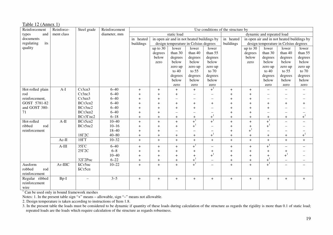
(2.23) When choosing type and grade of steel for reinforcement as well as rolled iron for embedded elements it is necessary to consider temperature conditions of use of the structure and loading schemes according to Table 12 and 13.
During installation works performed during cold seasons in climatic regions with design winter temperature less than 40 Celsius degrees below zero load-carrying capacity of structures with reinforcement which can be used only in heated buildings must be provided reasoning from design resistance of reinforcement with reduction
factor 0.7 and from design load with safety factor 0.1=fγ
(2.24) For lifting loops of members of prefabricated reinforced concrete and concrete
structures it is necessary to use hot-rolled reinforcement steel Ac-II of grade 10ГТ and A-I of grade ВСт3сп2 and ВСт3пс2.
If the installation of structures is possible by design winter temperature lower than 40 Celsius degrees below zero so it is possible to use steel of grade ВСт3пс2 for lifting loops.

Table 8
Design resistance of concrete for the first class limit states bR and btR , Mega Pascal (kilogram-force/cm2) if class of concrete as regards the
resistance to compression is
Resistance type Concrete Work condition coefficient
2bγ B2.5 B3.5 B5 B7.5 B10 B12.5 B15 B20 B25 B30 B35 B40 B45 B50 B55 B60
0.9 1.3 (13.3)
1.9 (19.4)
2.5 (25.5)
4.0 (4.08)
5.4 (55)
6.7 (68.5)
7.7 (78.5)
10.5 (107)
13.0 (133)
15.5 (158)
17.5 (178)
20.0 (204)
22.5 (230)
25.0 (230)
27.0 (275)
29.5 (300)
1.0 1.5 (15.3)
2.1 (21.4)
2.8 (28.6)
4.5 (45.9)
6.0 (61.2)
7.5 (76.5)
8.5 (86.7)
11.5 (117)
14.5 (148)
17.0 (173)
19.5 (199)
22.0 (224)
25.0 (255)
27.5 (280)
30.0 (306)
33.0 (336)
Axial compression (prism strength) Rb
Heavy-weight, fine and light-weight
1.1 1.6 (16.3)
2.3 (23.4)
3.1 (32.6)
4.9 (50)
6.6 (67.3)
8.2 (83.5)
9.4 (96)
12.5 (128)
16.0 (163)
19.0 (194)
21.5 (219)
24.0 (245)
27.5 (280)
30.5 (310)
33.0 (334)
36.5 (370)
0.9 0.18 (1.84)
0.23 (2.34)
0.33 (3.33)
0.43 (4.39)
0.51 (5.20)
0.59 (6.01)
0.67 (6.83)
0.80 (8.16)
0.95 (9.7)
1.10 (11.2)
1.15 (11.7)
1.25 (12.7)
1.30 (13.3)
1.40 (14.3)
1.45 (14.8)
1.50 (15.3)
1.0 0.20 (2.04)
0.26 (2.65)
0.37 (3.77)
0.48 (4.89)
0.57 (5.81)
0.66 (6.73)
0.75 (7.65)
0.90 (9.18)
1.05 (10.7)
1.20 (12.2)
1.30 (13.3)
1.40 (14.3)
1.45 (14.8)
1.55 (15.8)
1.60 (16.3)
1.65 (16.8)
Heavy-weight, fine1 and light-weight concrete with fine dense aggregate
1.1 0.22 (2.24)
0.29 (2.96)
0.41 (4.18)
0.53 (5.40)
0.63 (6.43)
0.73 (7.45)
0.82 (8.36)
1.00 (10.2)
1.15 (11.7)
1.30 (13.3)
1.45 (14.8)
1.55 (15.8)
1.60 (16.3)
1.70 (17.3)
1.75 (17.8)
1.80 (18.4)
0.9 0.18 (1.84)
0.23 (2.34)
0.33 (3.33)
0.43 (4.39)
0.51 (5.20)
0.59 (6.01)
0.66 (6.73)
0.72 (7.34)
0.81 (8.26)
0.90 (9.18)
1.00 (10.2)
1.10 (11.2)
– – – –
1.0 0.20 (2.04)
0.26 (2.65)
0.37 (3.77)
0.48 (4.89)
0.57 (5.81)
0.66 (6.73)
0.74 (7.55)
0.80 (8.16)
0.90 (9.18)
1.00 (10.2)
1.10 (11.2)
1.20 (12.2)
– – – –
Axial tension Rbt
Light-weight concrete with fine porous aggregate2
1.1 0.22 (2.24)
0.29 (2.96)
0.41 (4.18)
0.53 (5.40)
0.63 (6.43)
0.73 (7.45)
0.81 (8.26)
0.90 (9.18)
1.00 (10.2)
1.10 (11.2)
1.2 (12.2)
1.30 (13.3)
– – – –
1 For fine concrete of group Б (see Item 2.1) values Rbt are decreased by 15 percent. 2 For expanded-clay perlite concrete on expanded perlite sand values Rbt are decreased by 15 percent. Notes: 1. For porous concrete values Rb are taken the same like for light-weight concrete and values Rbt are multiplied by the coefficient 0.7.
2. Application conditions of work condition coefficient 2bγ are given in Item 3.1.
3. Design concrete resistance with the work condition coefficient 0.12 =bγ are taken in compliance with Table 13 of SNiP 2.03.01-84.

Table 9 (15)
Work condition coefficient of concrete Factors providing work condition coefficient insertion
graphical symbol number identification
1. Concreting in vertical position (concreting layer height is more than 1.5 m)
3bγ 0.85*
2. Concreting of monolithic poles and reinforced concrete columns with maximum section dimension less than 30 cm
5bγ 0.85
3. Alternate freezing and melting 6bγ See Table 10
4. Use of not protected against solar radiation structures in climatic sub-region IVA according to SNiP 2.01.01-82
7bγ 0.85
5. Concrete structures 9bγ 0.90
6. Concrete structures of heavy-weight concrete B35 and higher or of fine concrete B25 and higher
10bγ 0.3+ω≤1 (value ω see in
Item 3.14) 7. Concrete for joints filling of prefabricated elements
if thickness of the joint is less than 1/5 of the least dimension of the member section and less than 10 cm.
12bγ 1.15
*For members of porous concrete 3bγ = 0.80
Notes: 1. Work condition coefficients according pos. 3-5 must be considered during determination of design resistances Rb and Rbt, according other positions only during determination of Rb. 2. Work conditions coefficients of concrete are inserted independently on each other but at the same time their
product [including 2bγ (see Item 3.1)] must be no less than 0.45.
Table 10 (17)
Work conditions coefficient of
concrete 6bγ by alternate freezing and
melting of the structure
Structure application conditions
Design winter temperature of external air, Celsius degrees
for heavy-weight and fine concrete
for light-weight and porous
concrete Lower than 40 degrees below zero Lower than 40 degrees below zero up to 40 degrees below zero Lower than 5 degrees below zero up to 20 degrees below zero 5 degrees below zero and higher
0.70
0.85
0.90
0.95
0.80
0.90
1.00
1.00
Alternate freezing and melting
a) in water saturated state (see pos. 1a of Table 4);
b) in conditions of occasional water saturation (see pos. 1b of Table 4)
Lower than 40 degrees below zero 40 degrees below zero and higher
0.90
1.00
1.00
1.00
Notes: 1. Design winter temperature of external air is taken according to Item 1.8. 2. If concrete grade as regards resistance to frost in comparison with a required one according to Table 4 the coefficient of the present table can be decreased by 0.05 according to each decrease step but they cannot be more than 1.

Table 11 (18)
Prime concrete modulus of elasticity 310−⋅bE Mega Pascal (kilogram-force/cm2) if concrete class as regards resistance to compression is Concrete
B2.5 B3.5 B5 B7.5 B10 B12.5 B15 B20 B25 B30 B35 B40 B45 B50 B55 B60
Heavy-weigh: - of air hardening; - exposed to thermal treatment by air pressure
–
–
0.95
(96.9) 8.5
(86.7)
13.0 (133) 11.5 (117)
16.0 (163) 14.5 (148)
18.0 (184) 16.0 (163)
21.0 (214) 19.0 (194)
23.0 (235) 20.5 (209)
27.0 (275) 24.0 (245)
30.0 (306) 27.0 (275)
32.5 (331) 29.0 (296)
34.5 (352) 31.0 (316)
36.0 (367) 32.5 (332)
37.5 (382) 34.0 (347)
39.8 (398) 35.0 (357)
39.5 (403) 35.5 (362)
40.0 (408) 36.0 (367)
Fine concrete of groups: A–of air hardening;
exposed to thermal treatment by air pressure
Б– of air hardening;
exposed to thermal treatment by air pressure
В–of autoclave hardening
–
–
–
–
–
7.0
(71.4) 6.5
(66.3) 6.5
(66.3) 5.5
(56.1) –
10.0 (102) 9.0 (92) 9.0
(91.8) 8.0
(81.6) –
13.5 (138) 12.5 (127) 12.5 (127) 11.5 (117)
–
15.5 (158) 14.0 (143) 14.0 (143) 13.0 (133)
–
17.5 (178) 15.5 (158) 15.5 (158) 14.5 (148)
–
19.5 (199) 17.0 (173) 17.0 (173) 15.5 (158) 16.5 (168)
22.0 (224) 20.0 (204) 20.0 (204) 17.5 (178) 18.0 (184)
24.0 (245) 21.5 (219) 21.5 (219) 19.0 (194) 19.5 (199)
26.0 (265) 23.0 (235) 23.0 (235) 20.5 (209) 21.0 (214)
27.5 (280) 24.0 (245)
–
– 22.0 (224)
28.5 (291) 24.5 (250)
–
– 23.0 (235)
–
–
–
– 23.5 (240)
–
–
–
– 24.0 (245)
–
–
–
– 24.5 (250)
–
–
–
– 25.0 (255)
Light-weight and porous of grade as regards average density D:
800 1000 1200 1400 1600 1800 2000
4.0 (40.8)
5.0 (51.0)
6.0 (61.2)
7.0 (71.4)
–
–
–
4.5 (45.9)
5.5 (56.1)
6.7 (68.3)
7.8 (79.5)
9.0 (91.8)
–
–
5.0 (51.0)
6.3 (62.4)
7.6 (77.5)
8.8 (89.7) 10.0 (102) 11.2 (114)
–
5.5 (56.1)
7.2 (73.4)
8.7 (88.7) 10.0 (102) 11.5 (117) 13.0 (133) 14.5 (148)
–
8.0 (81.6)
9.5 (96.9) 11.0 (112) 12.5 (127) 14.0 (143) 16.0 (163)
–
8.4 (85.7) 10.0 (102) 11.7 (119) 13.2 (135) 14.7 (150) 17.0 (173)
–
–
10.5 (107) 12.5 (127) 14.0 (143) 15.5 (158) 18.0 (184)
–
–
–
13.5 (138) 15.5 (158) 17.0 (173) 19.5 (199)
–
–
–
14.5 (148) 16.5 (168) 18.5 (189) 21.0 (214)
–
–
–
15.5 (158) 17.5 (178) 19.5 (199) 22.0 (224)
–
–
–
–
18.0 (184) 20.5 (209) 23.0 (235)
–
–
–
–
–
21.0 (214) 23.5 (240)
–
–
–
–
–
–
–
–
–
–
–
–
–
–
–
–
–
–
–
–
–
–
–
–
–
–
–
–
Notes: 1. Fine concrete groups are given in Item 2.1. 2. For light-weight and porous concrete by intermediate values of concrete grade as regards average density initial elasticity modulus is taken according to linear interpolation. 3. For light-weight and porous concrete values Eb are given by use gravimetric humidity w which is 5 percent for concrete B12.5 and higher and 10 percent – for concrete B10 and lower. If
for concrete B10 and lower gravimetric humidity w determined in compliance with SNiP II-3-79** is more than 10 percent so values Eb can be increased according to Table 11 if relative grade as regards average density D (100+w)/110 (where D is concrete grade as regards average density).
4. For heavy-weight concrete exposed to autoclave treatment values Eb given in Table 11 for natural hardening concrete must be multiplied by the coefficient 0.75. 5. For not protected against solar radiation structures designed for use in climatic sub-region IVA according to SNiP 2.01.01-82 Eb given in Table 11 must be multiplied by the coefficient
0.85
19
Table 12 (Annex 1) Use conditions of the structure by
static load dynamic and repeated load
in open air and in not heated buildings by design temperature in Celsius degrees
in open air and in not heated buildings by design temperature in Celsius degrees
Reinforcement types and documents regulating its quality
Reinforce-ment class
Steel grade Reinforcement diameter, mm
in heated buildings
up to 30 degrees below zero
lower than 30 degrees below
zero up to 40
degrees below zero
lower than 40 degrees below
zero up to 55
degrees below zero
lower than 55 degrees below
zero up to 70
degrees below zero
in heated buildings
up to 30 degrees below zero
lower than 30 degrees below
zero up to 40
degrees below zero
lower than 40 degrees below
zero up to 55
degrees below zero
lower than 55 degrees below
zero up to 70
degrees below zero
Hot-rolled plain rod reinforcement, GOST 5781-82 and GOST 380-71
A-I Ст3сп3 Ст3пс3 Ст3кп3 ВСт3сп2 ВСт3пс2 ВСт3кп2 ВСт3Гпс2
6–40 6–40 6–40 6–40 6–40 6–40 6–18
+ + + + + + +
+ + + + + + +
+ + – + + – +
+ – – + + – +
+1 – – + – – +1
+ + + + + + +
+ + + + + + +
– – – + + – +
– – – + – – +
– – – + – – +1
A-II ВСт5сп2 ВСт5пс2 18Г2С
10–40 10–16 18–40 40–80
+ + + +
+ + + +
+ + – +
+1
+1 – +
+1
– – +1
+ + + +
+ + +1
+
+1
+1
– +
– – – +
– – – +1
Ас-II 10ГТ 10–32 + + + + + + + + + +
Hot-rolled ribbed rod reinforcement
A-III 35ГС 25Г2С 32Г2Рпс
6–40 6–8
10–40 6–22
+ + + +
+ + + +
+ + + +
+1
+ + +1
– + +1 –
+ + + +
+ + + +
+1
+ + +1
– + +1 –
– – – –
Ausform robbed rod reinforcement
Ат-IIIC БСт5пс БСт5сп
10–22 + + + +1 – + + +1 – –
Regular ribbed reinforcement wire
Bp-I – 3–5 + + + + + + + + + +
1 Can be used only in bound framework meshes Notes: 1. In the present table sign “+” means – allowable, sign “–” means not allowable. 2. Design temperature is taken according to instructions of Item 1.8. 3. In the present table the loads must be considered to be dynamic if quantity of these loads during calculation of the structure as regards the rigidity is more than 0.1 of static load;
repeated loads are the loads which require calculation of the structure as regards robustness.

Table 13 (Annex 2)
Design temperature, Celsius degrees
up to 30 degrees below zero lower than 30 degrees below zero up to 40 degrees below zero
Embedded elements characteristics
Steel grade according to GOST 380-71
sheet steel thickness, mm
Steel grade according to GOST 380-71
sheet steel thickness, mm
1. Calculated as regards the loads
a) static; b) dynamic and
repeated
ВСт3кп2 ВСт3пс6 ВСт3Гпс5 ВСт3сп5
4–30 4–10
11–30 11–25
ВСт3пс6 ВСт3пс6 ВСт3Гпс5 ВСт3сп5
4–25 4–10
11–30 11–25
2. Constructive (not calculated as regards any forces)
БСт3кп2 ВСт3кп2
4–10 4–30
БСт3кп2 БСт3кп2
4–10 4–30
Notes: 1. Design temperature is taken according to Item 1.8 instructions. 2. When using low-alloyed steel for example steel grade 10ГС2С1, 09ГС2С, 15 ХСНД as well as by design
temperature lower than 40 Celsius degrees below zero choosing of steel grade and electrodes must be performed as for steel welded structures in compliance with requirements of SNiP II-23-81.
3. Design resistances of steel are taken according to SNiP II-23-81.
Table 14 (19, 20)
Type and class of reinforcement
Standard resistances against tension Rsn and
design resistances against tension for the second class
limit states Rs,ser, mega Pascal (kilogram-
force/cm2)
Type and class of reinforcement
Standard resistances against tension Rsn and
design resistances against tension for the second class
limit states Rs,ser, mega Pascal (kilogram-
force/cm2)
Rod reinforcement A-I A-II A-III and Ат-IIIC
235 (2400) 295 (3000) 390 (4000)
Reinforcement wire of class Bp-I, diameter:
3 mm 4 mm 5 mm
410 (4200) 405 (4150) 395 (4050)
Table 15 (22, 23)
Design resistances of reinforcement for the first classes limit states, mega Pascal (kilogram-force/cm2)
against tension
Type and class of reinforcement
of longitudinal reinforcement Rs
Of cross reinforcement (stirrups and bend-up bars)
Rsw
against compression Rsc
Rod reinforcement of classes: A-I A-II A-III with diameter:
6–8 mm 10–40 mm
Ат-IIIC Reinforcement wire of class Bp-II with diameter:
3 mm 4 mm 5 mm
225 (2300) 280 (2850)
355 (3600) 365 (3750) 365 (3750)
375 (3850) 356 (3750) 360 (3700)
175 (1800) 225 (2300)
285 (5900)* 290 (3000)* 390 (3000)*
270 (2750); 300 (3050)** 265 (2700); 295 (3000)** 260 (2650); 290 (2950)**
225 (2300) 280 (2850)
355 (3600) 365 (3750) 365 (3750)
375 (3850) 365 (3750) 360 (3700)
* In welded frameworks for stirrups made of reinforcement A-III and Ат-IIIC with diameter less than 1/3 of diameter of longitudinal bars values Rsw are taken equal to 255 Mega Pascal (2600 kilogram-force/cm2).
** For bound frameworks.

21
Standard and design characteristics of reinforcement
(2.25) For characteristic strength of reinforcement Rsn it is necessary to take the least controlled values: - for rod reinforcement – physical yield limit; - for regular reinforcement wire – stress equal to 0.75 of rapture strength. Standard resistances Rsn for main types of non-prestressed reinforcement are given in Table 14.
(2.26) Design strength of reinforcement against tension and compression Rs and Rsc for the first class limit states are determined by means of dividing of characteristic strength into safety factor γs taken equal to:
a) 1.05 – for rod reinforcement A-I and A-II; 1.07 – for rod reinforcement Ат-IIIC and A-III with diameter 10–40 mm 1.10 – for rod reinforcement A-III with diameter 6–8 mm;
b) 1.10 – for reinforcement wire Bp-I.
Design extension strength of reinforcement for the second group limit states is taken equal to characteristic strength. Design extension and compression strength of reinforcement used during calculation according to the first class limit states are given in the Table 15 and by calculations according to the second class limit states – in Table 14.
(2.28) Design strength of cross reinforcement (stirrups and bend-up bars) Rsw get decreased in
comparison with Rs by means of multiplying by the work conditions coefficients 1sγ and
2sγ :
a) independently on type and class of reinforcement – by the coefficient 8.01 =sγ
considering unevenness of forces spread in reinforcement in the length dimension of the section;
b) for rod reinforcement of class A-III and Aт-IIIC with diameter no less than 1/3 of diameter of longitudinal bars and for reinforcement wire of class Bp-I in welded
frameworks – by the coefficient 9.02 =sγ considering the welded joint brittle failure
possibility.
Design strengths Rsw with consideration of the mentioned above work conditions
coefficients 1sγ and 2sγ are given in Table 15.
Besides if the considered section is locates in anchor zone of reinforcement so design
strengths Rs and Rsc are multiplied by work conditions coefficient 5sγ considering
incomplete anchorage of reinforcement and determined according to Item 3.44. For elements made of light-weight concrete B7.5 and less design resistances Rsw of cross
reinforcement A-I and Bp-I are to be multiplied by work conditions coefficient 8.07 =sγ .
(2.30) Values of reinforcement elasticity modulus Es are taken equal to:
210 000 mega Pascal (2 100 000 kilogram-force/cm2) – for reinforcement A-I and A-II 200 000 mega Pascal (2 000 000 kilogram-force/cm2) – for reinforcement A-III and Aт-IIIC 170 000 mega Pascal (1 700 000 kilogram-force/cm2) – for reinforcement Bp-I

22
3. CALCULATION OF CONCRETE AND REINFORCED CONCRETE MEMBERS
AS REGARDS THE FIRST CLASS LIMIT STATES.
3.1. For registration of loads influence on the concrete strength it is necessary to calculate concrete and reinforced concrete members as regards their strength:
a) regarding dead loads, long-term and short-term loads except loads of short duration (wind
loads, crane loads and other during production, transportation, installation, etc) as well as regarding special loads caused by deformation of collapsible, swelling, permanently frozen soils and soil of that kind; in that case design tension and compression strength of concrete
Rb and Rbt are taken according to Table 8 if 9.02 =bγ :
b) regarding all loads action including loads of short duration; in that case design strength of
concrete Rb and Rbt are taken according to Table 8 by 1.12 =bγ *
* If by consideration of special loads in compliance with instructions of norms it is necessary to insert a work
conditions coefficient (for example when consideration of earthquake loads) so it is taken 0.12 =bγ
If the structure is used in conditions favorable for concrete strength developing [hardening under the water, in humid soil or if surrounding air humidity is more than 75 percent (see
Item 1.8)] so calculation according to case “a” is made by 0.12 =bγ .
Strength conditions must be fulfilled as according to case “a” as according to case “b”. In case of absence of loads of short duration or emergency calculation is made only as according to case “b” if the following condition is met:
III FF 82.0< (1)
where FI is the force (moment MI, cross force QI or longitudinal force NI) from the loads
used by the calculation according to case “a”; at the same time in the calculations of sections normal to longitudinal axis of eccentric loaded members moment MI is taken relating to the axis going through the most stretched (or the least pressed) reinforcement rod, and for concrete members – relating to stretched or the leased compressed surface;
FII is the force from the loads used by calculation according to case “b”.
It is possible to make the calculation only according to case “b” if the condition (1) is not
fulfilled, taking design resistances Rb and Rbt (by 0.12 =bγ ) with the
coefficient 1.1/9.0 ≤= IIIbl FFγ .
For eccentric pressed members calculation according to un-deformed scheme values FI and FII can be determined without considering member deflection. For structures used in conditions favorable for concrete strength developing, condition (1)
becomes III FF 9.0< and the coefficient IIIbl FF /=γ .
23
CALCULATION OF CONCRETE MEMBERS STRENGTH
3.2. (3.1) Calculation of strength of concrete members must be made for sections normal to their longitudinal axis. According to work conditions of members they are calculated considering as well as without considering resistance of tensile zone of concrete.
Without consideration of resistance of tensile zone of concrete the calculation of eccentric pressed members mentioned in Item 1.7a considering that limit state is characterized by failure of compressed concrete. With consideration of resistance of tensile zone of concrete the calculation of members mentioned in Item 1.7b as well as members for which the presence of cracks is not allowed according to use conditions of the structure (members under the pressure of water, cornices, parapets, etc). At the same time it is considered that limit state is characterized by failure of tensile concrete (crack formation). In case if appearance of diagonal cracks is possible (for example members of T- or double T-section under lateral forces) it is necessary to make the calculation of concrete members according to condition (13). Besides it is necessary to make the calculation as regards local compression in compliance with Item 3.93.
Eccentric Pressed Members
3.3. (3.2, 1.21) During calculation of eccentric pressed concrete members it is necessary to take into account the occasional eccentricity of longitudinal force ea caused by not considered in the calculation factors. In any eccentricity ea is taken no less than
- 1/600 of the member length or of distance between its sections fixed against displacement;
- 1/30 of the member height; - 10 mm (for prefabricated members if there are no any other justified values ea)
For members of statically non-definable structures the value of eccentricity of longitudinal
force relating to center of gravity of the given section 0e is taken equal to eccentricity of
static calculation of the structure but no less than ea.
In members of statically non-definable structures eccentricity 0e is determined as a sum of
eccentricities according to static calculation of the structure and occasional one.
3.4. (3.3) By elasticity of members 14/0 >il (for rectangular sections by 4/0 >hl ) it is
necessary to consider the influence of deflections in the eccentricity plane of longitudinal force and in the plane normal to it on the load-carrying capacity of members by means of
multiplying of values 0e by coefficient η (see Item 3.7). In the calculation from eccentricity
plane of longitudinal force value 0e is taken equal to occasional eccentricity.
24
Use of eccentric pressed concrete members (except the cases provided in Item 1.7b) is not
allowed by eccentricities of longitudinal force considering deflections 0e η which are more
than: a) according to the loads combinations
- 0.9y……….by basic combination; - 0.95y….......by special load combination;
b) according to concrete class: - y –10……..by B10 and higher; - y –20……..by B7.5 an lower (here y is the distance from the center of gravity of the section to the most compressed concrete fiber). 3.5. (3.4) In eccentric compressed concrete members it is necessary to design constructive reinforcement in cases mentioned in Item 5.122.
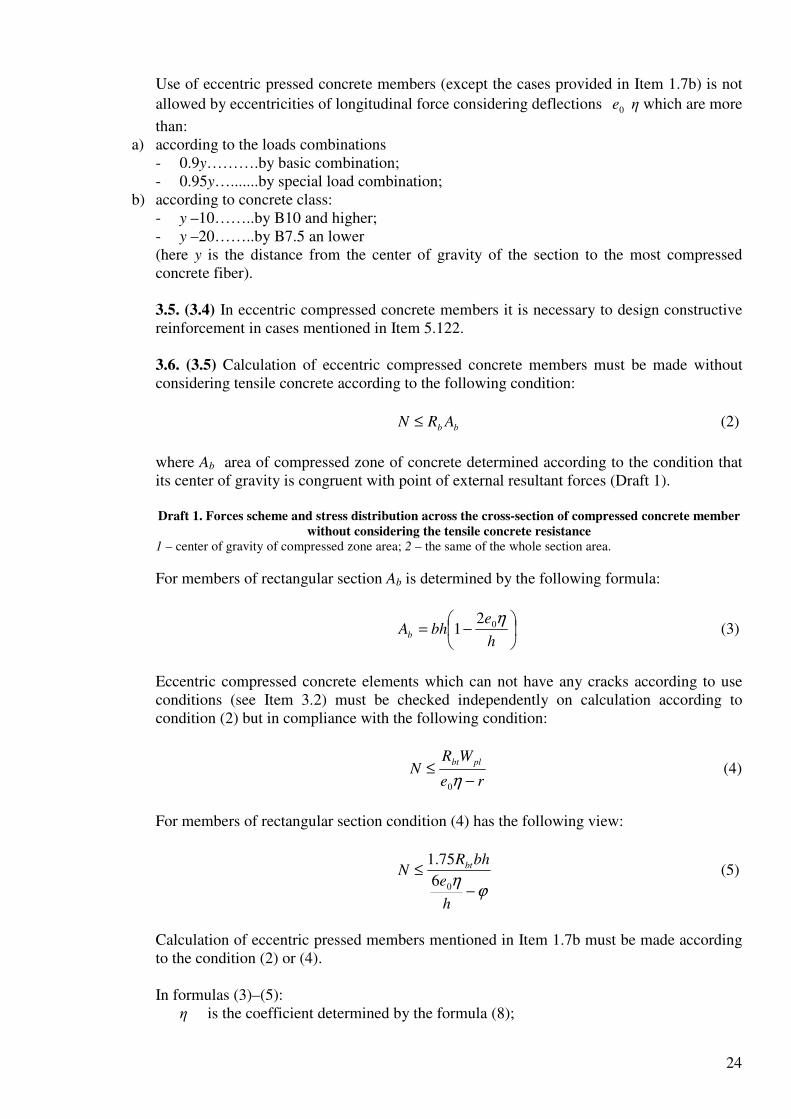
3.6. (3.5) Calculation of eccentric compressed concrete members must be made without considering tensile concrete according to the following condition:
bb ARN ≤ (2)
where Ab area of compressed zone of concrete determined according to the condition that its center of gravity is congruent with point of external resultant forces (Draft 1). Draft 1. Forces scheme and stress distribution across the cross-section of compressed concrete member
without considering the tensile concrete resistance
1 – center of gravity of compressed zone area; 2 – the same of the whole section area.
For members of rectangular section Ab is determined by the following formula:
−=
h
ebhAb
η021 (3)
Eccentric compressed concrete elements which can not have any cracks according to use conditions (see Item 3.2) must be checked independently on calculation according to condition (2) but in compliance with the following condition:
re
WRN
plbt
−≤
η0
(4)
For members of rectangular section condition (4) has the following view:
ϕη
−
≤
h
e
bhRN bt
06
75.1 (5)
Calculation of eccentric pressed members mentioned in Item 1.7b must be made according to the condition (2) or (4). In formulas (3)–(5):
η is the coefficient determined by the formula (8);

25
r is the distance from the center of gravity of the section to the heart point most distant from the tensile zone determined by the following formula:
A
Wr ϕ= (6)
serb
b
R ,
6.1σ
ϕ −= But is taken no more than 1.0;
bσ – Maximum compression stress determined as for elastic body;
Wpl – is sectional modulus for end tensile fiber considering non-elastic deformations of tensile concrete determined by the following formula:
002
b
b
pl Sxh
IW +
−= (7)
where Ib0 is moment of inertia of concrete pressed zone section area relating to zero line;
Sb0 is static moment of concrete pressed zone section area relating to zero line; h – x is the distance from the zero line to the tensile surface:
1
12
b
b
AA
Sxh
+=− ;
Ab1 is area of compressed zone of concrete supplemented in tensile zone with the rectangle with width b equal to the width of section along the zero line and with height h –x (Draft 2);
Sb1 is static moment of area Ab1 relating to stretched surface.
Draft 2. To definition Ab1.
It is possible to determine Wpl by the following formula:
0WWpl γ=
where γ – see in Table 29. 3.7. (3.6) Coefficient η considering deflection influence on the eccentricity of longitudinal
force 0e must be determined by the following formula:
crN
N−
=
1
1η (8)
where Ncr is relative critical force determined by the following formula:
+
+= 1.0
1.0
11.0
)/(
4.62
0 el
b
crhl
IEN
δϕ (9)
(here I is moment of inertia of concrete section). For elements of rectangular section formula (9) has the following view:
+
+= 1.0
1.0
11.0
)/(
533.02
0 el
b
crhl
AEN
δϕ (9a)
In formulas (9) and (9a):
lϕ – Coefficient considering influence of long duration of the load on the member
deflection:

26
1
11M
M l
l βϕ += (10)
but no more than 1+β here β is coefficient taken by Table 16;
M1 is the moment relating to tensile or the least compressed surface of the section caused by influence of dead loads, short-term and long-term loads;
M1l is the same but caused by dead loads and long-term loads; l0 is determined according to Table 17;
eδ – The coefficient taken equal to he /0 but no less than
be Rh
l01.001.05.0 0
min, −−=δ
(Here bR is in Mega Pascals).
Note. During calculation of the section according to cases “a” and “b” (see Item 3.1) it is possible to
determine min,eδ only once taking Rb by 1.02 =bγ .
Table 16 (30)
Concrete Coefficient β in formula (10)
1. Heavy-weight concrete 1.0
2. Fine concrete: group A group Б group В
1.3 1.5 1.0
3. Light-weight concrete - with artificial coarse and fine aggregate:
dense porous
- with natural coarse aggregate
1.0 1.5 2.5
4. Porous concrete 2.0 Note: Fine concrete groups are given in Item 2.1.
Table 17 (31)
Walls and columns support character Design length 0l of eccentric pressed concrete
members
1. with supports above and below: a) with hinges on both ends independently
on displacement of supports; b) by one end restraint and possible
displacement of supports for - multi-span buildings - one-span buildings
H
1.25H
1.50H
2. free supported 2.00H Symbols in Table 17: H – the height of the column (wall) within the first storey except the thickness of the floor slab or the height of free supported structure.
3.8. The calculation considering deflection of eccentric pressed concrete members of rectangular section made of heavy-weight concrete of class no higher than B20 can be made due to the diagram (Draft 3). At the same time the following condition must be met:

27
bhRN bnα≤
Where nα is determined according to the diagram (Draft 3) in compliance with values
he /0 and hl /0=λ .
Draft 3. Diagram of load carrying capacity of eccentric compressed concrete elements.
Explanation: ––––– by 0.1/ 11 =MM l
-------- By 5.0/ 11 =MM l
Bending Elements
3.9. (3.8) Calculation of bending concrete elements must be made according to the following condition:
plbtWRM ≤ (11)
where Wpl is determined by Formula (7); for members of rectangular section Wpl is taken equal to:
5.3
2bh
Wpl = (12)
Besides for members of T- and double T-section the following condition must be met:
btxy R≤τ (13)
Where xyτ – shear stresses determined as for elastic material at the level of center of
gravity of the section.
Examples of Calculation
Example 1. Given: a concrete panel of the wall between apartments, thickness h = 200 mm, height H = 2.7 mm manufactured vertically (in the mounting) of expanded-clay concrete with glass sand of class B15, concrete grade as regards average density is D1600 (Eb = 14 000 Mega Pascal) total load per 1 m of the wall is N = 900 kN, including dead load and long-term loads Nl = 540 kN; no load of short duration.
It is required to test the strength of the wall panel. Calculation is made according to Item 3.6 as regards the longitudinal force N =
900 kN applied with occasional eccentricity ae determined according to Item 3.3.
As 67.630
200
30==
h mm < 10 mm occasional eccentricity is taken equal to 10
mm, which means 100 =e mm. The connection of the panel above and below is considered to
be hinge connection, so design length 0l in compliance with Table 17 is 7.20 == Hl m.
As panel elasticity 45.132.0
7.20 >==h
l so the calculation is made with
consideration of deflection in compliance with Item 3.7.
Coefficient lϕ is determined according to formula (10) by 0.1=β (see Table
16). As eccentricity of longitudinal force doesn’t depend on load characteristics so here it is
possible to take 6.0900
5401 ===N
N
M
M ll ,
So 6.16.0111
1 =+=+=M
M l
l βϕ
As there are no loads of short duration so design concrete strength Rb in
compliance with Item 3.1 is taken considering the coefficient 90.02 =bγ that is bR = 7.7 mega

28
Pascal and in compliance with Table 9 considering work conditions coefficients 85.03 =bγ and
90.09 =bγ we get 89.590.085.07.7 =××=bR mega Pascal.
As 200
10306.089.501.05.1301.05.001.001.05.0 00
min, =>=⋅−⋅−=−−=h
eR
h
lbeδ so we
take 306.0min, == ee δδ .
Critical force Ncr is determined by formula (9a) taking section area A for 1 m of the wall length, that is A = 200×1000 = 200 000 mm2:
3
2
3
2
0
1018981.0306.01.0
11.0
5.136.1
2000001014533.01.0
1.0
11.0
)/(
533.0⋅=
+
+⋅
⋅⋅⋅=
+
+=
el
b
crhl
AEN
δϕN = 1898kN
from this 902.1
1898
9001
1
1
1=
−
=
−
=
crN
Nη
If we check condition (2) using formula (3):
954000200
902.1102120000089.5
21 0 =
⋅⋅−⋅=
−=
h
ebhRAR bbb
ηN = 954 kN > N = 900 kN,
that is the strength of the panel is provided. CALCULATION OF REINFORCED CONCRETE MEMBERS STRENGTH
3.10.(3.9) Calculation of reinforced concrete members as regards their strength must be made for the sections normal to their longitudinal axis as well as for inclined sections of the most dangerous direction. By torque moments it is necessary to check the strength of spatial sections in stretched zone bounded by torsion fracture of the most dangerous of all possible directions. Besides it is necessary to make the calculation of members as regards local loads (bearing stress, punching force, cleavage).
Bending Elements
3.11.(3.11) Calculation of sections normal to longitudinal axis of the member when bending moment acts in the plane of section symmetry axis and reinforcement is concentrated at surfaces perpendicular to the mentioned plane must be made in compliance with Items 3.15-3.23 according to the ratio between the value of relative
height of concrete compressed zone 0/ hx=ξ determined according to requirements
for equilibrium and the value of relative height of compressed concrete zone Rξ (see
Item 3.14) whereby limit state of limit state of the member comes at the same time with the stress equal to design strength Rs in the stretched reinforcement.
3.12. (3.18) Calculation of ring cross section bending elements if the ration of internal and
external radii is 5.0/ 21 ≥rr with reinforcement evenly spread in a circumferential
direction (if there are no less than 6 longitudinal bars) must be made as for eccentric compressed members in compliance with Items 3.69 and 3.70 by N = 0 and by bending
moment value instead of 0Ne .
3.13. Calculation of normal sections not mentioned in Items 3.11, 3.12 and 3.24 is made by formulas of general case of normal section calculation in compliance with Item 3.76
taking N = 0 in formula (154) and replacing eN by M (projection of bending moment on the plane perpendicular to the straight line which bounds compression zone) in condition (153). If symmetry axis of the section is not congruent with the moment plane or is absent

29
at all so location of the compressed zone bounding must conform to the additional condition of parallelism of moments planes of internal and external forces.
3.14. (3.12) Value Rξ is determined by the following formula:
−+
=
1.111
,
ω
σ
ωξ
usc
s
RR
(14)
where ω is characteristic of concrete compressed zone determined by the following formula:
bR008.0−= αω (15)
here α is the coefficient equal to:
0.85……for heavy-weight concrete 0.80……for fine concrete (see Item 2.1) of group A 0.75……for fine concrete of groups Б and В 0.80……for light-weight and porous concrete
500, =uscσ Mega Pascal by coefficient 9.02 =bγ (see Item 3.1);
400, =uscσ Mega Pascal by coefficient 0.12 =bγ or 1.12 =bγ ;
Rs, Rb are in mega Pascals.
Values ω and Rξ are given in table 18 – for members of heavy-weight concrete; in
Table 19 – for members of fine concrete of group A, light-weight and fine concrete
Table 18
Values ω, Rξ , αR and ψc for members of heavy-weight concrete of classes Concrete work
conditions coefficient
2bγ
Class of tensile
reinforcement
Symbol
B12.5 B15 B20 B25 B30 B35 B40 B45 B50 B55 B60
Any ω 0.796 0.788 0.766 0.746 0.726 0.710 0.690 0.670 0.650 0.634 0.614
A-III (Ø10–40) and BP-I (Ø4; 5)
Rξ αR ψc
0.662 0.443 4.96
0.652 0.440 4.82
0.627 0.430 4.51
0.604 0.422 4.26
0.582 0.413 4.03
0.564 0.405 3.86
0.542 0.395 3.68
0.521 0.381 3.50
0.500 0.376 3.36
0.484 0.367 3.23
0.464 0.355 3.09
A-II Rξ αR ψc
0.689 0.452 6.46
0.680 0.449 6.29
0.650 0.439 5.88
0.632 0.432 5.55
0.610 0.424 5.25
0.592 0.417 5.04
0.571 0.408 4.79
0.550 0.399 4.57
0.531 0.390 4.38
0.512 0.381 4.22
0.490 0.370 4.03
0.9
A-I Rξ αR ψc
0.708 0.457 8.04
0.698 0.455 7.82
0.674 0.447 7.32
0.652 0.439 6.91
0.630 0.432 6.54
0.612 0.425 6.27
0.591 0.416 5.96
0.570 0.407 5.68
0.551 0.399 5.46
0.533 0.391 5.25
0.510 0.380 5.01
Any ω 0.790 0.782 0.758 0.734 0.714 0.694 0.674 0.650 0.630 0.610 0.586
A-III (Ø10–40) and BP-I (Ø4; 5)
Rξ αR ψc
0.628 0.431 3.89
0.619 0.427 3.79
0.591 0.416 3.52
0.563 0.405 3.29
0.541 0.395 3.12
0.519 0.384 2.97
0.498 0.374 2.83
0.473 0.361 2.68
0.453 0.350 2.56
0.434 0.340 2.46
0.411 0.327 2.35
A-II Rξ αR ψc
0.660 0.442 5.07
0.650 0.439 4.94
0.623 0.429 4.6
0.593 0.417 4.29
0.573 0.409 4.07
0.551 0.399 3.87
0.530 0.390 3.69
0.505 0.378 3.49
0.485 0.367 3.34
0.465 0.357 3.21
0.442 0.344 3.06
1.0
A-I Rξ 0.681 0.673 0.645 0.618 0.596 0.575 0.553 0.528 0.508 0.488 0.464

30
αR ψc
0.449 6.31
0.447 6.15
0.437 5.72
0.427 5.34
0.419 5.07
0.410 4.82
0.400 4.59
0.389 4.35
0.379 4.16
0.369 3.99
0.356 3.80
Any ω 0.784 0.775 0.750 0.722 0.698 0.678 0.653 0.630 0.606 0.586 0.558
A-III (Ø10–40) and BP-I (Ø4; 5)
Rξ αR ψc
0.621 0.428 3.81
0.610 0.424 3.71
0.581 0.412 3.44
0.550 0.399 3.19
0.523 0.386 3.00
0.502 0.376 2.86
0.481 0.365 2.73
0.459 0.351 2.65
0.429 0.346 5.52
0.411 0.327 2.35
0.385 0.312 2.23
1.1
A-II Rξ αR ψc
0.650 0.439 4.97
0.642 0.436 4.84
0.613 0.425 4.49
0.582 0.413 4.16
0.556 0.401 3.91
0.534 0.391 3.72
0.514 0.382 3.53
0.485 0.361 3.34
0.477 0.363 3.29
0.442 0.344 3.06
0.417 0.330 2.91
A-I Rξ αR ψc
0.657 0.447 6.19
0.665 0.444 6.02
0.636 0.434 5.59
0.605 0.422 5.17
0.579 0.411 4.86
0.558 0.402 4.63
0.537 0.393 4.42
0.509 0.379 4.16
0.500 0.375 4.09
0.464 0.356 3.80
0.439 0.343 3.62
bR008.085.0 −=ω ;
−+
1.111
,
ω
σ
ωξ
usc
s
RR
; ( )RRR ξξα 5.01−= ;
−
=
1.11
,
ω
σψ
s
usc
c
R
Note: Values ω, Rξ αR and ψc given in Table 18 are calculated without considering coefficients biγ according to Table 9.
Table 19
Values ω, Rξ , αR and ψc for members of fine concrete of group A, light-weight
and porous concrete of classes
Concrete work
conditions coefficient
2bγ
Class of tensile
reinforcement
Symbol
B5 B7.5 B10 B12.5 B15 B20 B25 B30 B35 B40
Any ω 0.780 0.768 0.757 0.746 0.738 0.716 0.696 0.676 0.660 0.640
A-III (Ø10–40) and BP-I (Ø4; 5)
Rξ αR ψc
0.643 0.436 4.71
0.629 0.431 4.54
0.617 0.427 4.39
0.604 0.422 4.26
0.595 0.418 4.16
0.571 0.408 3.92
0.551 0.399 3.75
0.528 0.388 3.55
0.510 0.380 3.42
0.490 0.370 3.28
A-II Rξ αR ψc
0.671 0.446 6.14
0.657 0.441 5.92
0.644 0.437 5.73
0.632 0.432 5.55
0.623 0.429 5.43
0.599 0.420 5.12
0.577 0.411 4.86
0.556 0.401 4.63
0.539 0.394 4.46
0.519 0.384 4.27
0.9
A-I Rξ αR ψc
0.690 0.452 7.64
0.676 0.488 7.36
0.664 0.444 7.13
0.652 0.439 6.91
0.643 0.436 6.75
0.619 0.427 6.37
0.597 0.419 6.05
0.576 0.410 5.76
0.559 0.403 5.56
0.539 0.394 5.31
Any ω 0.774 0.761 0.747 0.734 0.725 0.700 0.672 0.648 0.628 0.608
A-III (Ø10–40) and BP-I (Ø4; 5)
Rξ αR ψc
0.609 0.424 3.70
0.594 0.418 3.56
0.578 0.411 3.42
0.563 0.405 3.29
0.553 0.400 3.22
0.526 0.388 3.01
0.496 0.373 2.82
0.471 0.360 2.67
0.451 0.349 2.55
0.432 0.339 2.45
A-II Rξ αR ψc
0.641 0.436 4.82
0.626 0.430 4.64
0.610 0.424 4.45
0.595 0.418 4.29
0.585 0.414 4.19
0.558 0.402 3.67
0.528 0.389 3.48
0.503 0.377 3.30
0.482 0.366 3.33
0.463 0.356 3.19
1.1
A-I Rξ αR ψc
0.663 0.443 6.00
0.648 0.438 5.71
0.633 0.433 5.54
0.618 0.427 5.34
0.608 0.423 5.21
0.581 0.412 4.89
0.551 0.399 4.57
0.526 0.388 4.33
0.506 0.378 4.14
0.486 0.368 3.97
bR008.080.0 −=ω ;
−+
1.111
,
ω
σ
ωξ
usc
s
RR
; ( )RRR ξξα 5.01−= ;
−
=
1.11
,
ω
σψ
s
usc
c
R
Note: Values ω, Rξ , αR and ψc given un Table 19are calculated without considering coefficients according to Table 9.
RECTANGULAR SECTIONS

31
3.15. Calculation of rectangular sections with reinforcement concentrated at compressed and tensile surface of the member (Draft 4), is made in the following manner according to the height of compressed zone:
bR
ARARx
b
sscss
'−= (16)
a) by Rh
xξξ ≤=
0
– for the condition
( ) ( )'5.0 0
'
0 ahARxhbxRM sscb −+−≤ (17)
b) by Rξξ > – for the condition
)'( 0
'2
0 ahARbhRM sscbR ++≤ α (18)
Where ( )RRR ξξα 5.01−=
At the same time design load-carrying capacity of the section can be increased by means
of replacing of value Rα by mR αα 2.08.0 + in the condition (18) where by 1≤ξ
( )ξξα 5.01−=m or according to table 20. Values Rξ and αR are determined according to
table 18 and 19. If 0≤x so the strength is checked according to the following condition
( )'0 ahARM ss −≤ (19)
Note. If the height of compressed zone determined considering of a half of compressed reinforcement,
'5.0 '
abR
ARARx
b
sscss ≤−
= so design load carrying capacity of the section can be increased if the
calculation will be made by formulas (16) and (17) without considering compressed reinforcement '
sA .
Draft 4. Loads scheme in rectangular cross section of bending reinforced concrete element.
3.16. It is recommended to design bending elements so that to provide the fulfillment of the
condition Rξξ < . It is possible not to meet this condition only in case when the section
area of stretched reinforcement is determined according to the calculation as regards the second class limit states or if it’s taken on the grounds of constructive solutions.
3.17. Checking of rectangular sections strength with single reinforcement is made
- by 0hx Rξ< in compliance with the condition:
( )xhARM ss 5.00 −≤ (20)
Where height of compressed zone is bR
ARx
b
ss=
- by 0hx Rξ≥ in compliance with the condition: 2
0bhRM bRα≤ (21)
at the same time design load carrying capacity of the section can be increased using
recommendations of Item 3.15b [ Rξ , Rα - see formula (4) or Table 18 and 19].
3.18. Choosing of longitudinal reinforcement is made in the following manner. It is necessary
to calculate the following value:
2
0bhR
M
b
m =α (22)
If Rm αα ≤ (see Table 18 and 19) so that means that compressed reinforcement is not
required.

32
If there is no compressed reinforcement so section area of tensile reinforcement is determined by the following formula:
0hR
MA
b
sζ
= (23)
Where ζ is determined according to Table 20 according to value mα .
If Rm αα > so it is necessary to enlarge the section or to increase the concrete grade, or to
fix compressed reinforcement in compliance with Item 3.19.
By consideration of the concrete work conditions coefficient 9.02 =bγ (see Item 3.1)
tensile reinforcement can be chosen according to Annex 2.
Table 20
ξ ζ mα ξ ζ
mα ξ ζ mα
0.01 0.02 0.03 0.04 0.05 0.06 0.07 0.08 0.09 0.10 0.11 0.12 0.13 0.14 0.15 0.16 0.17 0.18 0.19 0.20 0.21 0.22 0.23 0.24 0.25
0.995 0.990 0.985 0.980 0.975 0.970 0.965 0.960 0.955 0.950 0.945 0.940 0.935 0.930 0.925 0.920 0.915 0.910 0.905 0.900 0.895 0.890 0.885 0.880 0.875
0.010 0.020 0.030 0.039 0.049 0.058 0.068 0.077 0.086 0.095 0.104 0.113 0.122 0.130 0.139 0.147 0.156 0.164 0.172 0.180 0.188 0.196 0.204 0.211 0.219
0.26 0.27 0.28 0.29 0.30 0.31 0.32 0.33 0.34 0.35 0.36 0.37 0.38 0.39 0.40 0.41 0.42 0.43 0.44 0.45 0.46 0.47 0.48 0.49 0.50
0.870 0.865 0.860 0.855 0.850 0.845 0.840 0.835 0.830 0.825 0.820 0.815 0.810 0.805 0.800 0.795 0.790 0.785 0.780 0.775 0.770 0.765 0.760 0.755 0.750
0.226 0.234 0.241 0.243 0.255 0.262 0.269 0.276 0.282 0.289 0.295 0.302 0.308 0.314 0.320 0.326 0.332 0.338 0.343 0.349 0.354 0.360 0.365 0.370 0.375
0.51 0.52 0.53 0.54 0.55 0.56 0.57 0.58 0.59 0.60 0.62 0.64 0.66 0.68 0.70 0.72 0.74 0.76 0.78 0.80 0.85 0.90 0.95 1.00
–
0.745 0.740 0.735 0.730 0.725 0.720 0.715 0.710 0.705 0.700 0.690 0.680 0.670 0.660 0.650 0.640 0.630 0.620 0.610 0.600 0.575 0.550 0.525 0.500
–
0.380 0.385 0.390 0.394 0.399 0.403 0.407 0.412 0.416 0.420 0.428 0.435 0.442 0.449 0.455 0.461 0.466 0.471 0.476 0.480 0.489 0.495 0.499 0.500
– For bending moments of rectangular section:
0
'
bhR
ARAR
b
sscss −=ξ ;
( )2
0
0
' '
bhR
ahARM
b
ssc
m
−−α ; ( )ξξα 5.01−=m ; ξζ 5.01−= .
3.19. Cross sections areas of tensile As and compressed '
sA reinforcement corresponding to
minimum of their sum for members of concrete of class B30 and lower should be determined if compressed reinforcement is required according to the calculation (see Item 3.18), by the following formulas:
( )'4.0
0
2
0'
ahR
bhRMA
sc
b
s−
−= (24)
'055.0s
s
b
s AR
bhRA += (25)

33
If taken section area of compressed reinforcement '
sA far exceeds the value calculated by
formula (24) so section area of tensile reinforcement is determined according to actual
value of area '
sA by the following formula:
'
0 s
s
b
s AR
RbhA += ξ (26)
Where ξ is determined according to Table 20 depending on the value
( )0
'2
0
0
'
≥−−
=bhR
ahARM
b
ssc
mα which must conform to requirement Rm αα ≤
(see table 18 and 19).
T- AND DOUBLE T-SECTIONS 3.20. Calculation of sections which have a flange in compressed zone (T-sections and double
T-sections, etc) must be made depending on the compressed zone bounding position: a) if the bounding of compressed zone goes in the flange (Draft 5a) that is the following
condition is met: '''
sscffbss ARhbRAR +≤ (27)
The calculation is made as for rectangular section which is '
fb wide in compliance with
Items 3.15 and 3.17;
b) if the bounding of compressed zone goes in the rib (Draft 5b) that is condition (27) is not met, so the calculation is made according to the following condition
( ) ( ) ( ) ( )'5.05.0 0
''
0
''
0 ahARhhhbbRxhbxRM sscfffbb −+−−+−≤ (28)
At the same time concrete compressed zone height x is determined by the following formula:
( )bR
hbbRARARx
b
ffbsscss
''' −−−= (29)
And it is taken no more than 0hRξ (see Table 18 and 19).
If 0hx Rξ≥ so condition (28) can be written in the following form:
( ) ( ) ( )'5.0 0
''
0
''2
0 ahARhhhbbRbhRM sscfffbbR −+−−+≤ α (30)
Where Rα – see in Table 18 and 19.
At the same time it is necessary to consider the recommendations of Item 3.16.
Notes: 1. by variable height of a flange overhang it is possible to take the value '
fh equal to average height of
overhangs.
2. Compressed flange width '
fb inserted into the calculation must not exceed the values given in Item 3.23.
Draft 5. Compressed zone bounding position in T-section of bending reinforced concrete element.
a – in a flange; b – in a rib
3.21. Required section area of compressed reinforcement is determined by the following formula:
( ) ( )( )'
5.0
0
'0
''20'
ahR
hhhbbRbhRMA
sc
fffbbR
s−
−−−−=
α (31)

34
where Rα – see in Table 18 and 19.
3.22. Required section area of tensile reinforcement is determined in the following manner:
a) if compressed zone border goes in a flange, that is the following condition is met:
( ) ( )'5.0 0
''
0
''ahARhhhbRM sscfffb −+−≤ (32)
so section area of tensile reinforcement is determined as for rectangular cross section '
fb
wide in compliance with Items 3.18 and 3.19; b) if compressed zone border goes in a rib that is condition (32) is not met so cross section
of tensile section is determined by the following formula:
( )[ ]s
sscffb
sR
ARhbbbhRA
'''0 +−+ξ
(33)
where ξ is determined according to Table 20 depending on the value
( ) ( ) ( )2
0
0''
0'' '5.0
bhR
ahARhhhbbRM
b
sscfffb
m
−−−−−=α (34)
At the same time the condition Rm αα ≤ must be met (see Table 18 and 19).
3.23. (3.16) Value '
fb inserted into the calculation is taken according to the condition that
the width of an overhang to each side of the rib must be no less than 1/6 of the span of the member and no more than:
a) by cross ribs or by 2/11.0' −≥ hh f of the clear distance between longitudinal ribs;
b) without cross ribs (or if the distance between them is more than the distance between
longitudinal ribs) and '' 61.0 ff hhh −< ;
c) by console overhangs of a flange:
By '' 61.0 ff hhh −≥ ;
By '' 31.005.0 ff hhhh −<≤ ;
By hh f 05.0' < - overhangs are not taken into account.
Examples of Calculation
Rectangular section
Example 2. Given: the section with dimensions b = 300 mm, h = 600 mm, a = 40 mm;
9.02 =bγ (no loads of short duration); bending moment M = 200 KN·m; heavy-weight
concrete B15 ( 7.7=bR Mega Pascal); reinforcement A-II (Rs = 280 Mega Pascal).
It is required to determine the cross section area of longitudinal reinforcement.
Calculation. 560406000 =−=h mm. Longitudinal reinforcement is chosen according to
Item 3.18. Value mα is determined by Formula (22):
276.05603007.7
102002
6
2
0
=⋅⋅
⋅==
bhR
M
b
mα
According to Table 18 for a member of concrete B15 with reinforcement A-II by 9.02 =bγ , we
find that 449.0=Rα .
As 449.0276.0 =<= Rm αα so that means that compressed reinforcement is not required.
According to table 20 by 276.0=mα we find 835.0=ζ
Required cross section of tensile reinforcement is to be determined by formula (23):

35
1528560835.0280
10200 6
0
=⋅⋅
⋅==
hR
MA
s
sζ
mm2.
It is taken 2Ø28 + 1Ø25 ( 1598=sA mm2)
Example 3. Given: a section with dimensions b = 300 mm; h = 800 mm; a = 70 mm; tensile
reinforcement A-III (Rs = 365 Mega Pascal); its section area 2945=sA mm2 (6Ø25);
9.02 =bγ (no loads of short duration); heavy-weight concrete B25 (Rb = 13 Mega Pascal);
bending moment M = 550 kN·m. It is required to check the section strength.
Calculation. 730708000 =−=h mm. Section strength is calculated according to Item 3.17.
Value x is determined in the following manner:
27630013
2945365=
⋅
⋅==
bR
ARx
b
ss mm
According to table 18 for concrete B25 with reinforcement A-III by 9.02 =bγ , we
find 604.0=Rξ .
As 604.038.0730
276
0
=<=== Rh
xξξ
so the strength is to be checked according to condition (20):
( ) ( ) 6
0 104.6362765.073029453655.0 ⋅=⋅−⋅=− xhAR ss N· mm 4.636= kN·m > M = 550 kN ·m,
that means the strength is corresponding to norms. Example 4. Given: a section with dimensions b = 300 mm; h = 800 mm; a = 50 mm;
reinforcement A-III ( 365== scs RR Mega Pascal); bending moment with consideration of
crane load 780=IIM kN·m; moment without consideration crane load 670=IM kN·m;
heavy-weight concrete B15 ( 5.8=bR Mega Pascal by 0.12 =bγ ).
It is required to determine the section area of longitudinal reinforcement. Calculation is made as regards the total load correcting design resistance of concrete according to Item 3.1.
As 1.105.1670
7809.09.0 <===
I
II
blM
Mγ so we take 93.805.15.8 =⋅=bR Mega Pascal.
We calculate 750508000 =−h mm.
We determined required area of longitudinal reinforcement according to Item 3.18. Value mα
is determined according to Formula (22):
518.075030093.8
107802
6
2
0
=⋅⋅
⋅==
bhR
M
b
mα
As 42.0518.0 =>= Rm αα (see Table 18 by 0.12 =bγ ) by given dimensions of the section and
concrete class it is required compressed reinforcement. The following calculation is made according to Item 3.19. Taking 30'=a mm we determine required section of compressed and tensile reinforcement by formulas (24) and (25):
( )674
30750365
75030093.84.010780
)'(
4.0 216
0
2
0' =−
⋅⋅⋅−⋅=
−
−=
ahR
bhRMA
sc
b
s mm2
3702674365
93.875030055.055.0 '0 =+⋅⋅⋅
=+= s
s
b
s AR
RbhA mm2.
We take 763' =sA mm2 (3Ø18); As = 4021 mm2 (5Ø32).

36
Example 5. Given: a section with dimensions b = 300 mm; h = 700 mm; a = 50 mm; a’ = 30
mm; heavy-weight concrete B30 (Rb = 15.5 MPa by 9.02 =bγ ); reinforcement A-III
( 365=sR MPa); section area of compressed reinforcement 942' =sA mm2 (3Ø20); bending
moment M = 580 kN·m. It is required to determined section area of tensile reinforcement.
Calculation: 650507000 =−=h mm. The calculation is made considering the area of
compressed reinforcement according to Item 3.19.
Value mα is determined in the following manner:
( )187.0
6503005.15
)30650(94236510580'2
6
2
0
0
'
=⋅⋅
−⋅−⋅=
−−=
bhR
ahARM
b
ssc
mα ;
413.0187 =<= Rm αα (See Table 18)
According to Table 20 by 187=mα we find 21.0=ξ . Required area of tensile reinforcement is
determined by Formula (26):
2680942365
5.1565030021.0'0 =+⋅⋅⋅
=+= s
s
b
s AR
RbhA
ξ mm2
We take 3Ø36 (Rs = 3054 mm2). Example 6. Given: a section with dimensions b = 300 mm; h = 700 mm; a = 70 mm; a’ = 30
mm; heavy-weight concrete B25 (Rb = 13 MPa by 9.02 =bγ ); reinforcement A-III
( 365== scs RR MPa); section area of stretched reinforcement 4862=sA mm2 (6Ø32), of
tensile reinforcement 339' =sA mm2 (3Ø12); bending moment M = 600 kN·m.
It is required to check the section strength.
Calculation: 630707000 =−=h mm. The section strength is checked in compliance with
Item 3.15. The height of compressed zone x is determined by Formula (16):
( )420
30013
3394826365'
=⋅
−=
−=
bR
ARARx
b
sscss mm
We find 604.0=Rξ and 422.0=Rα according to table 18.
As 420=x mm 380630604.00 =⋅=> hRξ mm so section strength is to be checked according
to condition (18):
( ) ( ) 62
0
'2
0 104.7273063033936563030013422.0' ⋅=−⋅+⋅⋅⋅=−+ ahARbhR sscbRα N·mm =
4.727 kN·m > M = 600 kN·m, that is section strength is provided. T-SECTIONS AND DOUBLE T-SECTIONS
Example 7. Given: a section with dimensions 1500' =fb mm, 50' =fh mm, and b = 200 mm,
h = 400 mm, a = 40 mm; heavy-weight concrete B25 (Rb = 13 MPa by 9.02 =bγ );
reinforcement A-III (Rs = 365 MPa); bending moment M = 300 kN·m. It is required to determine the section area of longitudinal reinforcement.
Calculation: 360404000 =−=h mm. The calculation is made according to Item 3.22 on the
hypothesis that compressed reinforcement is not required according to the calculation.

37
We check the condition (32) taking 0' =sA ;
( ) 6'
0
'' 106.326505.036050150013)5.0( ⋅=⋅−⋅⋅=− fffb hhhbR N·mm = 326.6 kN·m, that is the
border of compressed zone goes in the flange and the calculation is made as for rectangular section with the width b = b’f = 1500 mm in compliance with Item 3.18.
We determine the value mα :
422.0119.0360150013
103002
6
2
0
=<=⋅⋅
⋅== R
b
mbhR
Mαα (See Table 18),
that is compressed reinforcement is not required. The section area of stretched reinforcement is calculated by formula (23). For that according to
Table 20 by 119.0=mα we find 938.0=ζ and
2434360938.0365
10300 6
0
=⋅⋅
⋅==
hR
MA
s
sζ
mm2
We take 4Ø28 (As = 2463 mm2).
Example 8. Given: a section with dimensions 400' =fb mm, 120' =fh mm, and b = 200 mm,
h = 600 mm, a = 60 mm; heavy-weight concrete B15 (Rb = 7.7 MPa by 9.02 =bγ );
reinforcement A-III (Rs = 365 MPa); bending moment M = 270 kN·m. It is required to determined section area of tensile reinforcement.
Calculation: 540606000 =−=h mm. The calculation is made in compliance with Item 3.22
on the hypothesis that compressed reinforcement is not required.
As ( ) 6'
0
'' 104.1771205.05401204007.7)5.0( ⋅=⋅−⋅⋅=− fffb hhhbR N·mm = 177.4 kN·m < M =
= 270 kN·m, that is the border of compressed zone goes in the rib, section area of stretched reinforcement is calculated by formula (33).
For that we determine the value mα :
( ) ( ) ( )44.0404.0
5402007.7
1205.05401202004007.710270)5.0(2
6
2
0
'0
''
=<=⋅⋅
⋅−⋅−−⋅=
−−−= R
b
fffb
mbhR
hhhbbRMαα
(see Table 18), so compressed reinforcement is not required.
According to Table 20 by 404.0=mα we find 563.0=ξ , then
( )[ ] ( )[ ] 1789365
7.7120200400540200563.0''
0 =−+⋅⋅=−+=s
b
ffsR
RhbbbhA ξ mm2.
We take 4Ø25 (As = 1964 mm2).
Example 9. Given: a section with dimensions 400' =fb mm, 100' =fh mm, b = 200 mm,
h = 600 mm, a = 70 mm; heavy-weight concrete B25 (Rb = 13 MPa by 9.02 =bγ ); tensile
reinforcement A-III (Rs = 365 MPa), its section area As = 1964 mm2 (4Ø25); 0' =sA ; bending
moment M = 300 kN·m. It is required to check the strength of the section.
Calculation: 530706000 =−=h mm. The section strength is checked in compliance with
Item 3.20, taking 0' =sA . As 7168601964365 =⋅=ss AR N >
52000010040013'' =⋅⋅=ffb hbR N, the border of compressed zone goes in the rib. The section
strength is checked according to condition (28). For that we determine the height of compressed zone x by Formula (29):

38
( )20013
100200400131964365)( ''
⋅
−−⋅=
−−=
bR
hbbRARx
b
ffbss =
= 176 mm 320530604.00 =⋅=< hRξ mm ( Rξ is found according to table 18);
( ) ( )+⋅−⋅⋅=−−+− 1765.053017620013)5.0()(5.0 '
0
''
0 ffhbb hhhbbRxhbxR
( ) 6101.327)1005.0530(10020040013 ⋅=⋅−−+ N·mm = 327.1 kN·m > M =300 kN·m,
that is the strength of the section is provided. MEMBERS WORKING IN SKEW BENDING 3.24. Calculation of rectangular sections, T-sections, double T- and L-sections of members
working in skew bending can be made taking the form of compressed zone according to Draft 6, at the same time the following condition must be met:
( )[ ] sxscxovwebbx SRSxhARM ++−≤ ,10 3/ (35)
where Mx is a component of a bending moment in plane of axes x (for axes x and y we take to perpendicular axes going trough the center of gravity of section of tensile reinforcement parallel to the section sides; for a section with a flange axis x is taken parallel to the rib plane);
ovbweb AAA −= (36)
Ab compressed concrete zone area equal to:
b
sscss
bR
ARARA
'−= (37)
Aov is the area of the most compressed overhang of a flange; x1 the measurements of compressed zone along the most compressed lateral side
of the section determined by the following formula:
( )ysyscyovwebb
webb
MSRSAbR
ARx
−++=
,0
2
13
2 (38)
b0 is the distance from the center of gravity of the section of tensile reinforcement to the most compressed lateral face of the rib (side);
Sov,y is static moment of the area Aov in the plane of axis y relating to axis x;
Ssy is static moment of the area '
sA in the plane of axis y relating to axis x;
My is a component of bending moment in the plane of axis y; Sov,x is static moment of the area Aov in the plane of axis x relating to axis x;
Ssx is static moment of the area '
sA in the plane of axis x relating to axis y.
Draft 6. Form of compressed zone in cross section of reinforced concrete element working in biaxial
bending
a – T-section; b – rectangular section; 1 – plane of bending moment; 2 – center of gravity of tensile reinforcement section.
If considered in the calculation tensile reinforcement rods are located in plane of axis x (Draft 7) value x1 is determined by the following formula:
βctgAttx web22
1 ++−= (39)
Where
−+
−= 00
,,5.1 hctgb
A
SctgSt
web
xovyovβ
β;
β is angle of dip of the bending moment plane to axis x that is ctgβ = Mx/My.

39
Drafts 7. Section with tensile reinforcement rods in the plane of axis x.
Formula (39) must be also used independently on reinforcement location if it is necessary to determine limit value of bending moment by given angle β. During calculation of rectangular sections values Aov, Sov,x and Sov,y in formulas (35), (36), (38) and (39) are taken equal to zero.
If ovb aA < or '
1 2.0 fhx < so that means that the calculation is made as for rectangular
section '
fbb = wide.
If the following condition is met:
ov
web
bb
Ax
=<
5.11 (40)
(where ovb the width of the least compressed overhang of the flange), so the calculation is
made without considering skew bending that is according to formulas of Items 3.15 and 3.20 as regards moment M = Mx at the same time it is necessary to check the condition (41) taking x1 as by skew bending. During determination of the value Ab by formula (37) the stress in the closest to compressed zone border tensile bar must be no less than Rs that corresponds to the following condition:
( ) R
iovi
ov
ihtgbb
xtgbξ
θ
θξ ≤
+=
==
0
'
0
1
'
(41)
Where Rξ – see Tables 18 and 19
ii hb 00 , are the distances from the rod under consideration to the most compressed and
lateral surface of the rib (side) and to the most compressed surface normal to axis x (see Draft 4);
'
ovb – The width of the most compressed overhang;
θ – Angle of slope of the line bounding the compressed zone to axis y; value of tgθ is determined by the following formula:
webA
xtg
2
21=θ .
If condition (41) is not met so the calculation of the section is made by means of step-by-step approximation and replacing in formula (37) value Rs for each tensile rod by stress values equal to:
( ) sicsi R1/ −ξωψσ But no more than Rs,
Where ωψ ,c are taken according to Table 18 and 19, at the same time axes x and y must
be drawn through resultant of forces in tensile rods.
During design of structures value iξ must not exceed value Rξ more than by 20 percent,
at the same time it is possible to make only one repeated calculation with replacement of
values Rs in formula (37) for tensile rods for which Ri ξξ > by stresses equal to :
( )s
ic
si R3
21/ +−ξωψσ (42)
By repeated calculation value x1 is determined by formula (39) independently on location of tensile rods.
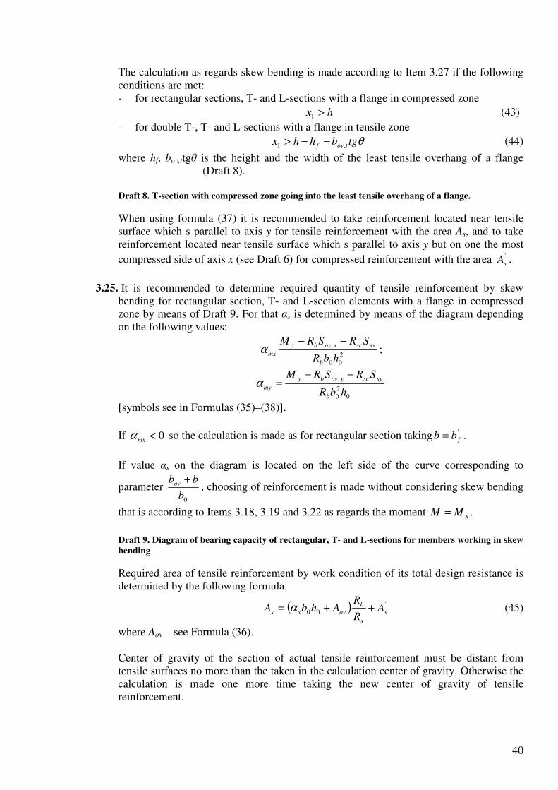
40
The calculation as regards skew bending is made according to Item 3.27 if the following conditions are met: - for rectangular sections, T- and L-sections with a flange in compressed zone
hx >1 (43)
- for double T-, T- and L-sections with a flange in tensile zone
θtgbhhx tovf ,1 −−> (44)
where hf, bov,ttgθ is the height and the width of the least tensile overhang of a flange (Draft 8).
Draft 8. T-section with compressed zone going into the least tensile overhang of a flange.
When using formula (37) it is recommended to take reinforcement located near tensile surface which s parallel to axis y for tensile reinforcement with the area As, and to take reinforcement located near tensile surface which s parallel to axis y but on one the most
compressed side of axis x (see Draft 6) for compressed reinforcement with the area '
sA .
3.25. It is recommended to determine required quantity of tensile reinforcement by skew
bending for rectangular section, T- and L-section elements with a flange in compressed zone by means of Draft 9. For that αs is determined by means of the diagram depending on the following values:
2
00
,
hbR
SRSRM
b
sxscxovbx
mx
−−α ;
0
2
0
,
hbR
SRSRM
b
syscyovby
my
−−=α
[symbols see in Formulas (35)–(38)].
If 0<mxα so the calculation is made as for rectangular section taking '
fbb = .
If value αs on the diagram is located on the left side of the curve corresponding to
parameter 0b
bbov +, choosing of reinforcement is made without considering skew bending
that is according to Items 3.18, 3.19 and 3.22 as regards the moment xMM = .
Draft 9. Diagram of bearing capacity of rectangular, T- and L-sections for members working in skew
bending
Required area of tensile reinforcement by work condition of its total design resistance is determined by the following formula:
( ) '
00 s
s
b
ovss AR
RAhbA ++= α (45)
where Aov – see Formula (36). Center of gravity of the section of actual tensile reinforcement must be distant from tensile surfaces no more than the taken in the calculation center of gravity. Otherwise the calculation is made one more time taking the new center of gravity of tensile reinforcement.

41
Work condition of tensile reinforcement with total design resistance is the fulfillment of condition (41). For members made of concrete B25 and lower condition (41) is always met if value αs on Draft 9 is located inside the area bounded by coordinate axes and a curve corresponding
to parameter 0
' / bbov .
If condition (41) is not met so it is necessary to put (increase) compressed reinforcement or increase class of concrete or to increase dimensions of the section (especially dimensions of the most compressed overhang).
Values αs on the diagram must not be located between axis myα and a curve
corresponding to parameter hh /0 . Otherwise x is more than h and the calculation is made
according to Item 3.27. 3.26. The calculation of skew bending of rectangular and double T-shaped symmetric sections
with symmetrically located reinforcement can by made according to Item 3.76 taking N = 0.
3.27. For sections not settled in Items 3.24–3.26 as well as if conditions (43) and (44) are met and if reinforcement is spread on the section that disturbs the determination of values As
and '
sA and location of centers of gravity of tensile and compressed reinforcement,
calculation as regards skew bending must be made using the formula of general case of normal section calculation (see Item 3.76) considering instructions of Item 3.13. Order of use of formulas of general case is the following: 1) two perpendicular to each other axes x and y are drawn through the center of gravity
of the section of the most tensile rod if possible parallel to section sides; 2) By means of step-by-step approximation it is chosen the location of a line bounding
compressed zone so that the equation (154) by N = 0 was met after insertion into it
the value siσ determined by formula (155). At the same time angle of slope of this
line θ is taken as a permanent one and equal to angle of slope of neutral axis determined as for elastic body;
3) there are determined moments of internal stresses relating to axes x and y – Myu and Mxu.
If both these moments are more or less then correspondent components of external moment (My or Mx) so the strength of the section is correspondingly provided (if more) and not provided (if less). If one of moments (for example Myu) is less than the correspondent component of external moment My and the other moment is more than the component of external moment (that is Mxu < Mx) so it is taken a larger angle of slope θ (more than the one taken earlier) and the same calculation is made one more time. Examples of Calculation
Example 10. Given: reinforced concrete collar beam of the roof with the slope 1:4 (ctgβ
= 4); section and location of reinforcement is corresponding to Draft 10; 9.02 =bγ (no
loads of short duration); heavy-weight concrete B25 (Rb = 13 MPa); stretched

42
reinforcement class A-III (Rs = 365 MPa); its section area As = 763 mm2 (3Ø18); 0' =sA ;
bending moment in a vertical plane M = 82.6 kN·m. It is required to check the strength of the section. Calculation. In compliance with Draft 10 it is:
3603
301304000 =
⋅−−=h mm;
903
30112020 =
⋅+⋅=b mm;
752
150300' =−
== ovov bb mm;
902
2080' =+=fh mm
Draft 10. To calculation example 10.
1 – bending moment plane; 2 – center of gravity of tensile reinforcement section
According to Formula (37) we determine the area of compressed zone of concrete Ab:
2142013
763365=
⋅==
b
ss
bR
ARA mm2.
Area of the most compressed overhang of a flange and static moments of its area relating to axes x and y are correspondingly equal to:
67509075'' =⋅=fovov hbA mm2;
( ) ( ) 4'
0, 1006.862/759067502/ ⋅=+=+= ovovyov bbAS mm3;
( ) ( ) 4'
0, 106.2122/9036067502/ ⋅=+=+= fovxov hhAS mm3.
As ovb AA > so the calculation is continued as for T-section.
14670675021420 =−== ovbweb AAA mm2.
The components of bending moment in the plane of axes y and x are correspondingly equal to (by ctgβ = 4):
2041
6.82
1sin
22=
++==
ββ
ctg
MMM y kN·m;
80420 =⋅== βctgMM yx kN·m
According to formula (38) we determine dimensions of compressed zone of concrete x1
relating to the most compressed side of the section, taking 0=syS :
( ) 2232000000)8606001467690(13
1467013
3
2
3
2 2
,0
2
1 =−+⋅
⋅=
−+=
yyovwebb
webb
MSAbR
ARx mm
Let’s check condition (40):
8.9775150
146705.15.1 2
=+
⋅=
+ ov
web
bb
A mm < x1 = 233 mm
So the calculation is to be continued by formulas foe skew bending.
Let’s check condition (41) for the least tensile rod. According to Draft 10 300 =ib mm,
370304000 =−=ih mm:
695.1146702
223
2
212 =
⋅==
webA
xtgθ ;

43
( ) ( )604.064.0
370695.17530
223695.175
00
1 =>=++
+⋅=
++
== R
iovi
ov
ihtgbb
xtgbξ
θ
θξ
(see Table 18). Condition (41) is not met. Let’s make one more calculation; in formula (37) we replace
value Rs for the least tensile rod by stress sσ determined by formula (42), correcting
values h0 and b0.
From Table 18 we have 746.0=ω and 26.4=cψ .
( ) ( )sss
ic
s RRR 902.03
2164.0/746.026.4
3
21/=
+−=
+−=
ξωψσ
As all rods have the same diameter so new values bA , 0b and 0h will be equal to:
207203
902.0221420 =
+=bA mm2;
0.92902.02
30902.012020 =
+
⋅+⋅=b mm;
7.359902.02
301304000 =
+
⋅−−=h mm
Then let’s determine values yovS , , xovS , and Aweb:
4
, 1041.87)2/7592(6750 ⋅=+=yovS mm3;
4
, 104.212)2/907.359(6750 ⋅=+=xovS mm3;
13970675020720 =−=webA mm2.
Value x1 we determine by formula (39):
8.1597.35949213970
212400048741005.15.1 00
,,=
−⋅+
−⋅=
−+
−= hctgb
A
SctgSt
web
xovyovβ
βmm
7.21041397028.1598.1592 22
1 =⋅⋅++−=++−= βctgAttx web mm
Let’s check the section strength according to condition (35) taking 0=sxS :
( )[ ] 64
,10 102.80104.2123
7.2107.35913970133/ ⋅=
⋅+
−=+− xovwebb SxhAR N·mm >
> Mx = 80·106 N·mm, that is the section strength is provided. Example 11. According to data of Example 10 it is necessary to choose the area of tensile reinforcement by moment in vertical plane M = 64 kN·m. Calculation. Components of bending moment in the plane of axes y and x are equal to:
6245.1541
1064
1sin
2
6
2=⋅=
+
⋅=
+==
ββ
ctg
MMM y kN·m
We determine required quantity of reinforcement according to Item 3.25.
Taking values 0,,,, '
,0,000 == sysyyvxv SSSShb according to Example 10 we find values
mxα and myα :
227.03609013
104.2121310622
46
2
00
,=
⋅⋅
⋅⋅−⋅=
−=
hbR
SRM
b
xovbx
mxα ;

44
114.03609013
1006.8613105.152
46
0
2
0
,=
⋅⋅
⋅⋅−⋅=
−=
hbR
SRM
b
yovby
myα .
As 0>mxα so the calculation is continued as for T-section.
As the point with coordinates 227.0=mxα and 114.0=myα on Drawing 9 is located on
the right side of the curve corresponding to parameter 5.290
75150
0
=+
=+
b
bb ov and on
the left side of the curve corresponding to parameter 83.090
75
0
==b
bov so the
reinforcement will work with total design resistance that is condition (41) is met. Required area of tensile reinforcement is determined according to formula (45).
According to Draft 9 by 227.0=mxα and 114.0=myα we find 25.0=sα
Then by 0' =sA we have
( ) ( ) 529365
1367503609025.000 =+⋅⋅=+=
s
b
ovssR
RAhbA α mm2.
We take rods 3Ø16 ( 603=sA mm2) and arrange them as it is shown on Draft 10.
Example 12. Given: hinged wall plate of a public building with a span 5.8 m with the cross section according to Draft 11; light-weight concrete B3.5, average density grade D1100; reinforcement A-III; load on the panel at stage of use – dead weight and weight of located above glass (including the pier) 3 m height 3.93 kN/m2, from plane of the panel – wind load 0.912 kN/m2. It is required to check the strength of the panel at stage of use. Calculation. First we determine bending moments in the middle section of the panel in the plane and out of the plane of the panel. According to Item 2.13 we determine the load of dead weight of the panel. As class of light weight concrete is lower than B12.5 so density of concrete is
121011001.11.1 =⋅== Dγ kg/m3. So the load of dead weight of the panel will be:
94.401.012102.134.001.0 =⋅⋅⋅=⋅= γbhqw kN/m
And considering safety factor 2.1=fγ (as 1800<γ kg/m3)
92.594.42.1 =⋅=wq kN/m
Load of located above glazing weight is 8.11393.3 =⋅=gq kN/m.
Total load in the panel plane is:
72.178.1192.5 =+=+= gwx qqq kN/m,
and moment of this load in the middle of the panel is:
5.748
8.572.17
8
2
=⋅
==lq
M x
x kN·m
Wind load per 1 m of the panel length considering the load of located above and below glazing is:
( ) 83.332.1912.0 =+=yq kN/m
and moment of this load is:
1.168
8.583.3
8
22
=⋅
==lq
My
y kN·m

45
As reinforcement is spread unevenly on the section so the strength is to be checked by formulas of a general case in compliance with Item 3.76 (considering Item 3.13). We’ll give numbers to all rods as it is shown on Draft 11. Through the center of the most stretched rod 1 we draw axis x parallel to dimension h = 1195 mm and axis y parallel to dimension b = 340 mm.
Draft 11. To example of calculation 12
! – 8 – rods
Angle θ between axis y and the straight line bounding the compressed zone is taken as for the calculation of elastic body as regards biaxial bending:
67.234.0
195.1
5.74
1.1622
=
=
==
b
h
M
M
I
I
M
Mtg
x
y
y
x
x
yθ .
In the first approximation we determine the area of concrete compressed zone by formula (37) that is taking all rods with total design strength, at the same time rod 8 is taken as a compressed one and other ones are taken as tensile ones. For rods 1, 2, 7, 8 (Ø10) we have Rs = Rsc = 365 MPa, and for rods 3 – 6 (Ø6) – Rs = 355 MPa, then:
126250113355236365 =⋅+⋅=ss RR N;
286505.78365' =⋅=ssc AR N.
As there is a wind load so value Rb is taken considering the coefficient 1.12 =bγ that is
3.2=bR MPa.
424403.2
28650126250'
=−
=−
=b
sscss
bR
ARARA mm2
Area of compressed zone on the assumption that it’s of triangular form is determined by
formula θtg
xAb
2
2
1= where x1 is dimension of compressed zone by the section side h so x1
is:
476424407.26221 =⋅⋅== bAtgx θ mm < h = 1195 mm.
Dimension y1 of compressed zone by section side b is:
17276.2
47611 ===
θtg
xy mm < b = 340 mm,
that is compressed zone is of triangular form in fact. If we put these dimension on Draft 11 so we can see that rod 8 is located in compressed
zone and all other rods are in tensile zone. Let’s check the stress siσ in the closest to
tensile zone border rods that is in rods 6 – 8 by formula (155), determining the ratios
ih
x
0
=ξ by formula xiyi
iatga
x
==
θξ 1 where xia and yia are the distances from i-rod to
the most compressed side of the section in direction of axes x and y.
Taking 400, =uscσ MPa, 782.03.2008.08.0008.08.0 =⋅−=−= bRω we get
13841082
1782.0
1.1
782.01
4001
1.11 1
,−=
−
−
=
−
−
=ii
usc
siξξξ
ωω
σσ (MPa)
The calculations we summarize in the following Table: Rod number
siA , mm2 yia , mm xia , mm xiyi atga +θ iξ ssi R<>σ

46
, mm MPa
6 7 8
28.3 78.5 78.5
40 300 40
555 80 80
662 881 187
0.719 0.54
2.545
120.9<355 620>365
-959<-365
During determination of Ab it was taken incorrect stress only for rod 6: 355 MPa instead
of 120.9 MPa. In this rod we take stress larger than the calculated one, – 1606 =sσ MPa.
From equation (150) by N = 0 we determine value Ab:
400803.2
286503.2816085355263365=
−⋅+⋅+⋅==
∑b
sisi
bR
AA
σ mm2.
By a similar way we determine 4634008067.221 =⋅⋅=x mm.
So for rod 6 we have:
699.0662
46316 ==
+=
xiyi atga
x
θξ ;
1641384699.0
10826 =−=sσ MPa,
That is value 6sσ is close to the excepted one and so it is not necessary to calculate
values Ab and x1 one more time. Let’s determine moments of internal forces relating to axes y and x – Mxu and Myu.
( ) −
−⋅=−Σ−
−=
3
4631115400803.2
31
11 xixsisixbbxu aaA
xaARM σ
( ) ( ) ( )−−⋅+−−⋅⋅− 55511153.28160355101511153.282355
( )( ) 6104.788011155.783655.78365 ⋅=−⋅−⋅− N·mm =
+ 78.4 kN·m > 5.74=xM kN·m;
17367.2
46311 ===
θtg
xy mm;
( ) −
−⋅=−Σ−
−=
3
173300400803.2
31
11 yiysisiybbyu aaA
yaARM σ
( )( ) =−⋅−⋅+⋅+⋅− 403005.783653.281603.283555.78365 61055.18 ⋅= N·mm = 18.5 kN·m > 1.16=yM kN·m.
As both internal moments exceed both components of external moment so the section strength is provided.
CALCULATION OF SECTIONS INCLINED TO LONGITUDINAL AXIS OF THE MEMBER
3.28. (3.29) It is necessary to calculate inclined sections of reinforced concrete members to
provide the strength: - against lateral force along inclined band between inclined cracks in compliance with
Item 3.30; - against lateral force along inclined crack for members with cross reinforcement in
compliance with Items 3.31-3.39, for members without cross reinforcement - in compliance with Items 3.40 and 3.41;
- against bending moment along inclined crack in compliance with Items 3.42-3.47.
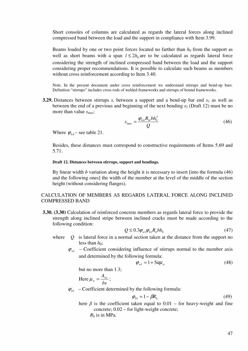
47
Short consoles of columns are calculated as regards the lateral forces along inclined compressed band between the load and the support in compliance with Item 3.99. Beams loaded by one or two point forces located no farther than h0 from the support as
well as short beams with a span 02hl ≤ are to be calculated as regards lateral force
considering the strength of inclined compressed band between the load and the support considering proper recommendations. It is possible to calculate such beams as members without cross reinforcement according to Item 3.40. Note. In the present document under cross reinforcement we understand stirrups and bend-up bars. Definition “stirrups” includes cross rods of welded frameworks and stirrups of bound frameworks.
3.29. Distances between stirrups s, between a support and a bend-up bar end s1 as well as between the end of a previous and beginning of the next bending s2 (Draft 12) must be no more than value smax:
Q
bhRs btb
2
04max
ϕ= (46)
Where 4bϕ – see table 21.
Besides, these distances must correspond to constructive requirements of Items 5.69 and 5.71. Draft 12. Distances between stirrups, support and bendings.
By linear width b variation along the height it is necessary to insert [into the formula (46) and the following ones] the width of the member at the level of the middle of the section height (without considering flanges).
CALCULATION OF MEMBERS AS REGARDS LATERAL FORCE ALONG INCLINED COMPRESSED BAND
3.30. (3.30) Calculation of reinforced concrete members as regards lateral force to provide the
strength along inclined stripe between inclined cracks must be made according to the following condition:
0113.0 bhRQ bbw ϕϕ≤ (47)
where Q is lateral force in a normal section taken at the distance from the support no less than h0;
1wϕ – Coefficient considering influence of stirrups normal to the member axis
and determined by the following formula:
ww αµϕ 511 += (48)
but no more than 1.3;
Herebs
Asw
w =µ ;
1bϕ – Coefficient determined by the following formula:
bb Rβϕ −= 11 (49)
here β is the coefficient taken equal to 0.01 – for heavy-weight and fine concrete; 0.02 – for light-weight concrete;
Rb is in MPa.

48
CALCULATION OF INCLINED SECTION AS REGARDS LATERAL FORCE ALONG INCLINED CRACK Members with constant height reinforced by stirrups without bend-up bars
3.31. The strength of inclined section as regards lateral force along inclined crack (Draft 13) is
made according to the following condition:
swb QQQ +≤ (50)
where Q is lateral force of external load located on one side of inclined section under review; by vertical load on the top surface of the member value Q is taken in the normal section going through the most distant from the support end of inclined section; by the load on the bottom surface of the member or within the height of its section it is also possible to take value Q as the most distant from the support end of inclined section if stirrups installed according to Item 3.97 are not considered in the present calculation; at the same time it is necessary to consider absence of live load within the inclined section;
Qb is cross force taken by concrete and equal to:
c
MQ b= , (51)
( ) 2
02 1 bhRM btfbb ϕϕ += ; (52)
2bϕ – Coefficient considering concrete type and determined by Table 21;
fϕ – Coefficient considering influence of compressed flanges of T- and double-T-
section elements and determined by the following formula:
( )0
''
75.0bh
hbb ff
f
−=ϕ (53)
but no more than 0.5,
At the same time value )( 'bb f − is taken no more than '3 fh ;
reinforcement in the rib is anchored in the flange where there is cross reinforcement connecting flange overhangs with a rib;
c is projection length of inclined axis upon member determined according to Item 3.32.
Draft 13. Forces model in inclined section of elements with stirrups during its calculation as regards lateral
force
Table 21
Coefficients Concrete
2bϕ 3bϕ 4bϕ
Heavy-weight concrete Fine concrete Light-weight concrete
- D1900 - D1800 and lower by fine aggregate
dense porous
2.00 1.70
1.90
1.75 1.50
0.6 0.5
0.5
0.4 0.4
1.5 1.2
1.2
1.0 1.0
Value Qb is taken no less than ( ) 03min, 1 bhRQ btfbb ϕϕ += ( 3bϕ - see Table 21);
Qsw is cross force carried by stirrups equal to:

49
0cqQ swsw = (54)
here qsw is force in stirrups per length unit of the member within inclined section determined by the following formula:
s
ARq swsw
sw = ; (55)
c0 is projection length of inclined crack upon longitudinal axis of the member taken equal to:
sw
b
q
Mc =0 (56)
But no more than c and no more than 02h as well as no less than 0h if 0hc >
At the same time for stirrups installed according to the calculation (that is when requirements of Items 3.40 and 3.41 are not met) it is necessary to follow the following requirement:
0
min,
2h
b
sw ≥ (57)
It is possible not to follow the requirement (57) if in formula (52) it is considered such
reduced value bRbt when condition (57) becomes an equation that is if3
22
02b
b
swb qhMϕ
ϕ= ;
in that case it is always 00 2hc = but no more than c.
3.32. By checking of condition (50) in general case it is taken a row of inclined sections by
different values c not exceeding the distance from the support to the section with
maximum bending moment and no more than ( ) 032 / hbb ϕϕ .
If point loads act on the element so values c are taken equal to the distances from the support to the point of the force impact (Draft 14).
Draft 14. Location of design inclined sections by point loads
1 – inclined section checked as regards the lateral force Q1; 2 – the same of force Q2
By calculation of the member as regards the distributed load q value c is taken equal to
sw
b
q
M and if swqq 65.01 > so it is necessary to take
sw
b
Mc
+=
1
where q1 is
determined in the following manner:
a) if there is actual distributed load qq =1 ;
b) If load q includes live load which reduces to equivalent distributed load v (when diagram of moment M of accepted in the calculation load v always bends round the
diagram M of any actual live load), 2/1 vgq += (where g is dead continuous load).
At the same time value Q is taken equal to cqQ 1max − where maxQ is lateral force in
support section.
3.33.Required density of stirrups shown by means of swq (see Item 3.31) is determined in the
following manner: a) by point forces located at the distances ci of the support acting on the element, for
each inclined section with the projection length ci not exceeding the distance to the

50
section with maximum bending moment value qsw is determined according to the
coefficient bi
bii
iQ
QQ −=χ by one of the following formulas:
If0
0min,
02
ææh
c
Q
Q
bi
b
ii =< ,
1æ
æ
0
0
0
)(+
=i
ii
iswc
Qq ; (58)
If0
0 ææc
ci
ii ≤≤ ,
0
)(c
QQq bii
isw
−= ; (59)
If00
æh
c
c
c i
i
i ≤< ,
( )
b
bii
iswM
QQq
2
)(
−= ; (60)
If0
æh
ci
i > ,
0
)(h
QQq bii
isw
−= ; (61)
(here h0 is taken no more than ci).
Finally it is taken maximum value )(iswq .
In formulas of Item 3.33: Q is lateral force in the normal section located at the distance ci from the
support; Qbi is determined by formula (51) by c = ci;
bb MQ ,min, See Item 3.31;
c0 is taken equal to ci but no more than 2h0;
b) by distributed load q required density of stirrups is determined by the following formulas:
By 6.0
maxbiQ
Q ≤
b
b
swM
QQq
4
2
1
2
max −= ; (62)
By 6.0
1max1
0
b
b
b QQQ
h
M>>+
( )
b
b
swM
QQq
2
1max −= ; (63)

51
In both cases swq is taken no less than
−
0
1max
2h
QQ b ;
By 1
0
max b
b Qh
MQ +≥
0
1max
h
QQq b
sw
−= (64)
In case if calculated value swq doesn’t correspond to condition (57) so it must be
calculated by the following formula: 2
0
max
2
1
3
2
0
max1
3
2
0
max
222
−
+−+=
h
h
h
b
b
b
b
swϕ
ϕ
ϕ
ϕ,
Here 11 2 qMQ bb =
maxQ – Lateral force in the support section;
32 ,, bbbM ϕϕ – see in Item 3.31;
q1 see in Item 3.32.
3.34. If from the support to the span density of stirrups reduces from 1swq to 2swq (for example
by stirrups spacing increase) it is necessary to check condition (50) by values c increasing
l1 the length of the member part with stirrups quantity 1swq (Draft 15). At the same time
value swQ is taken equal to:
By 011 clc <−
( )( )121011 lcqqcqQ swswswsw −−−= ;
By 01102 clcc >−>
( )12 lcqQ swsw −= ;
By 021 clc >−
022cqQ swsw = ,
Where 0201 ,cc are determined by formula (56) by swq equal to 1swq and 2swq .
Draft 15. to the calculation of inclined sections by density of stirrups alterations.
By distributed load acting on the element the length of the part with density 1swq is taken
no less than value l determined in the following manner:
If 211 swsw qqq −> ,
21
1max0111
/
swsw
swb
cqQcqcMcl
−
+−+−= ,
Where ( )211 swsw
b
qqq
Mc
−−= but no more than 0
3
2 hb
b
ϕ
ϕ;
At the same time if 211 56.1 swsw qqq −>
So21 sw
b
Mc
+= ;

52
If 211 swsw qqq −≤
( )01
1
012min,max
1 cq
cqQQl
swb−
+−=
Here 1q - see Item 3.32.
If condition (57) is not met for the value 2swq so the length l1 is calculated by values
322
2
0 /2 bbswb qhM ϕϕ= and 20min, 2 swb qhQ = corrected according to Item 3.31, at the same
time the sum 012min, cqQ swb + is taken no less than the uncorrected value min,bQ .
Members with a constant height reinforced by bend-up bars
3.35. Strength test of inclined section against lateral force for members with bend-up bars is made according to condition (50) with addition to the right part of the condition (50) the following value:
θsin,, incsswimcs ARQ = (65)
Where incsA , – section area of bend-up bars crossing dangerous inclined crack with the
projection length 0c ;
θ is angle of slope of bend-up bars to the longitudinal axis of the member.
Value 0c is taken equal to the length of the member part within the inclined section under
review for which the expression 0
,0,c
MQcqQQQ b
incsswbincssw ++=++ gets minimum
value. For that it is necessary to consider the parts from the end of inclined section or from the end of bend-up bar within the length c to the beginning of the bend-up bar which is close to the support (Draft 16) at the same time the length of the part is taken no
more than 0c determined by formula (56) and inclined cracks not crossing bend-up bars
by values 0c less than the ones determined by formula (56) are not considered in the
calculation.
Draft 16. For determination of the most dangerous inclined section for members with bend-up bars by
calculation as regards lateral force.
1 – 4 – possible inclined sections; 5 – considered inclined section
On Draft 16 the most dangerous inclined crack corresponds to minimum value of the following expressions:
1 – 011,01 /sin cMARcq bincsswsw ++ θ ;
2 – 022,02 /sin cMARcq bincsswsw ++ θ ;
3 – 033,03 /sin cMARcq bincsswsw ++ θ ;
4 – 022,1,0 /sin)( cMAARcq bincsincsswsw +++ θ
[here 0c - see formula (56)].
Values c are taken equal to the distances from the support to the ends of bend-up bars as well as to points of concentrated forces; besides it is necessary to examine inclined
sections which cross the last plane of bend-up bars and end at the distance 0c determined
by formula (56) from the beginning of the last and next to the last planes of bend-up bars (Draft 17).

53
Location of bend-up bars must meet the requirements of Items 3.29, 5.71 and 5.72.
Draft 17. Location of inclined sections of the member with bend-up bars
1 – 4 – calculated inclined sections.
Variable height elements with cross reinforcement
3.36. (3.33) Calculation of members with inclined compressed surfaces as regards lateral forces is made according to Items 3.31, 3.32, 3.34 and 3.35 considering recommendations
of Items 3.37 and 3.38 taking maximum value 0h as working height (Draft 18, a).
It is also recommended to make calculation of members with inclined stretched sections as regards lateral forces in compliance with Items 3.31, 3.32, 3.34 and 3.35 taking
maximum value 0h within inclined section (Draft 18, b).
Draft 18. Beams with variable height and inclined surface
a – compressed; b – tensile
Angle β between compressed and tensile surfaces of member must meet the requirement 4.0<βtg .
3.37. For beams without bend-up bars with height evenly increasing from the support to the
span (see Draft 18) calculated as regards distributed load q inclined section is tested according to condition (50) by the most disadvantageous value c determined in the following manner:
if the following equation is met:
swincsw qqqq 5.256.01 −< (66)
so value c is determined in by the following formula
1
1
qqqq
Mc
swincinc
b
++= (67)
if condition (66) is not met so value c is calculated by the following formula:
1
1
qqq
Mc
swinc
b
++= (At the same time cc =0 ) (68)
As well as if )4/( 2
011 hMq bsw < ,
1
1
2 qtgqq
Mc
swinc
b
++=
β(At the same time 00 2hc = ) (69)
Here βϕ 2
2 btgRq btbinc = ;
1bM – Value bM determined by formula (52) as for support section of beam with
working height 01h without considering enlarged footing b;
β – Angle between compressed and tensile surfaces of the beam;
1q – See Item 3.32.
Working height h0 is taken equal to βctghh += 010 .
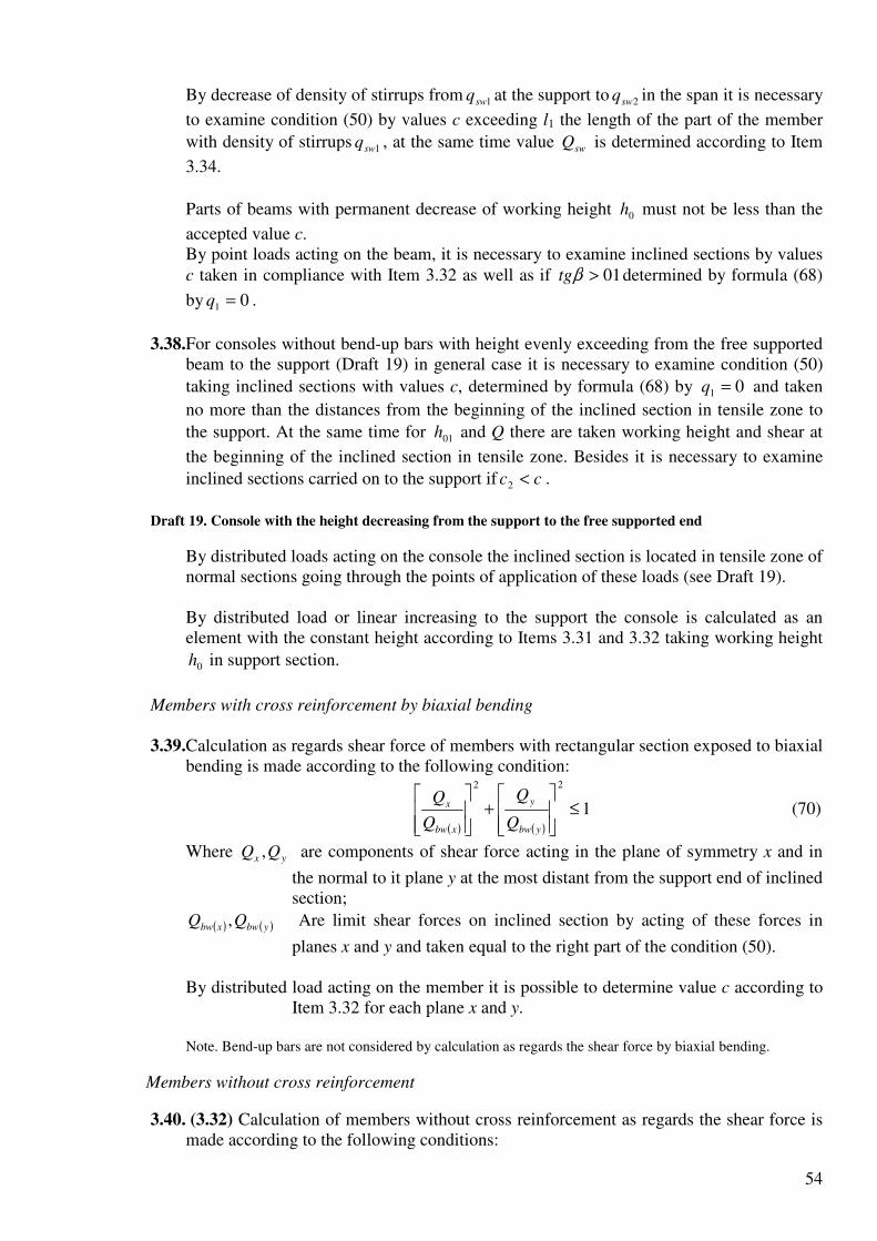
54
By decrease of density of stirrups from 1swq at the support to 2swq in the span it is necessary
to examine condition (50) by values c exceeding l1 the length of the part of the member
with density of stirrups 1swq , at the same time value swQ is determined according to Item
3.34.
Parts of beams with permanent decrease of working height 0h must not be less than the
accepted value c. By point loads acting on the beam, it is necessary to examine inclined sections by values c taken in compliance with Item 3.32 as well as if 01>βtg determined by formula (68)
by 01 =q .
3.38.For consoles without bend-up bars with height evenly exceeding from the free supported
beam to the support (Draft 19) in general case it is necessary to examine condition (50)
taking inclined sections with values c, determined by formula (68) by 01 =q and taken
no more than the distances from the beginning of the inclined section in tensile zone to
the support. At the same time for 01h and Q there are taken working height and shear at
the beginning of the inclined section in tensile zone. Besides it is necessary to examine
inclined sections carried on to the support if cc <2 .
Draft 19. Console with the height decreasing from the support to the free supported end
By distributed loads acting on the console the inclined section is located in tensile zone of normal sections going through the points of application of these loads (see Draft 19). By distributed load or linear increasing to the support the console is calculated as an element with the constant height according to Items 3.31 and 3.32 taking working height
0h in support section.
Members with cross reinforcement by biaxial bending
3.39.Calculation as regards shear force of members with rectangular section exposed to biaxial bending is made according to the following condition:
( ) ( )
1
22
≤
+
ybw
y
xbw
x
Q
Q
Q
Q (70)
Where yx QQ , are components of shear force acting in the plane of symmetry x and in
the normal to it plane y at the most distant from the support end of inclined section;
( ) ( )ybwxbw QQ , Are limit shear forces on inclined section by acting of these forces in
planes x and y and taken equal to the right part of the condition (50). By distributed load acting on the member it is possible to determine value c according to
Item 3.32 for each plane x and y. Note. Bend-up bars are not considered by calculation as regards the shear force by biaxial bending.
Members without cross reinforcement
3.40. (3.32) Calculation of members without cross reinforcement as regards the shear force is made according to the following conditions:

55
a) 0max 5.2 bhRQ bt≤ (71)
Where maxQ – maximum shear force at the support surface;
b) c
bhRQ btb
2
04ϕ≤ (72)
where Q is shear force at the end of inclined section;
4bϕ – Coefficient determined by Table 21;
c – Is projection length of inclined section starting from the support; value c is
taken no more than 0max 5.2 hc = .
In continuous flat slabs with constrained edges (connected with other elements or having
supports) it is possible to divide the mentioned value maxc by the coefficient α:
hb /05.01+=α (73) but no more than 1.25.
By testing of condition (72) in general case it is taken value c no more than maxc .
By point loads acting on the element values c are taken equal to the distances from the support to the application points of these loads (Draft 20).
Draft 20. Location of the most disadvantageous sections in elements without cross reinforcement.
1 – inclined section tested as regards shear force action Q1; 2 – the same for force Q2
During calculation of the element as regards distributed load if the following condition is met:
( )2
0max
41
/ hc
bRq btbϕ
≤ (74)
so value c in condition (72) is taken equal to maxc and if condition (74) is not met so
1
40
q
bRhc btbϕ
= (75)
here q1 is taken by distributed loads in compliance with Item 3.32 and by continuous load with linear variable density it is taken equal to average density of the support part with the length equal to a quarter of the beam (slab) span or to a half of the console overhang
but no more than maxc .
3.41.For elements with variable height of the section during testing of condition (71) value 0h
is taken in support section and during testing of condition (72) as average value 0h within
inclined section.
For elements with the section height increasing by increase of shear force value maxc is
taken equal to βtg
hc
25.11
5.2 01max
+= at the same time for continuous flat plates mentioned in
Item 3.40 βα tg
hc
25.1
5.2 01max
+= ,
Where 01h – working height in support section;
β is angle between tensile and compressed surfaces of the element; α see formula (73) where h can be taken according to support section.

56
By distribution load acting on such element value c in condition (72) is taken equal to:
( )bRqtghc
btb21
201/4/
1
ϕβ += (76)
but no more than maxc where q1 – see Item 3.40.
CALCULATION OF INCLINED SECTIONS AS REGARDS BENDING MOMENT 3.42. (3.35) Calculation of elements as regards bending moment to provide the strength along
inclined crack (Draft 21) must be made according to the following condition:
incsincsswswswswsss zARzARzARM ,,Σ+Σ+≤ (77)
where M is moment of external load located on one side of considered inclined section relating to the axis which is perpendicular to the moment action plane and going through the point of application of resultant force Nb in compressed zone (Draft 22);
sss zAR – Moments sum relating to the same axis from forces in longitudinal
swswsw zARΣ Reinforcement, stirrups and bend-up bars crossing stretched zone of
incsincssw zAR ,,Σ inclined section;
incssws zzz ,,, – The distances from the planes of longitudinal reinforcement, stirrups
and bend-up bars to the mentioned axis.
Draft 21. Forces scheme in inclined section by its calculation as regards bending moment.
Draft 22. Determination of design value of the moment by calculation of inclined section a – for a free supported beam; b – for a console
The height of compressed zone measured by a line normal to longitudinal axis of the member is determined according to the requirements of equilibrium of forces projections in concrete of compressed zone and in reinforcement crossing the inclined section onto a longitudinal axis of the member according to Items 3.15 and 3.20. If there are bend-up bars in the member so in the numerator for value x it is necessary to add value
θcos,incssw ARΣ (where θ is angle of inclination of bend-up bars to the longitudinal axis
of the member).
Value zs can be taken equal to xh 5.00 − but considering compressed reinforcement no
more than 'ah − .
Value swswsw zARΣ by constant stirrups quantity is determined by the following formula: 25.0 cqzAR swswswsw =Σ (78)
Where swq is force in the stirrups per unit of length (see Item 3.31);
c is the length of the projection of incline section onto the longitudinal axis of the member measured between points of application of resultant forces in tensile reinforcement and compressed zone (see Item 3.45).
Values incsz , for each plane of bend-up bars are determined by the following formula:

57
( ) θθ sincos 1, aczz sincs −+= (79)
where a1 is the distance from the beginning of the inclined section to the beginning of a bend-up bar in tensile zone (see Draft 21).
3.43. (3.35) Calculation of inclined sections as regards the moment is made in points of break
or bending of longitudinal reinforcement as well as at surfaces of end free support of a beams and at free end of consoles if there is no special anchors of longitudinal reinforcement. Besides, calculation of inclined sections as regards the moment is made in points of abrupt change of the element configuration. It is possible not to make calculation of inclined sections as regards the moment if conditions (71) and (72) are met by multiplying their right parts by 0.8 and by values c no
more than max8.0 c .
3.44. If inclined section crosses longitudinal inclined reinforcement without anchors so design
strength of this reinforcement Rs within anchorage zone must be decreased by means of
multiplying it by the work condition coefficient 5sγ equal to:
an
x
sl
l=5γ (80)
where lx is the distance from the end of reinforcement to the cross point of inclined section with longitudinal reinforcement;
lan anchorage zone length determined by the following formula:
dR
Rl an
b
s
anan
∆+= λω (81)
Here anan λω ∆, are coefficients taken equal to:
For end free supports of beams 5.0=anω , 8=∆ anλ
For free ends of consoles 7.0=anω ; 11=∆ anλ
In case of use of plain rods coefficient anω is taken equal to 0.8 for supports of beams
and to 1.2 for ends of consoles. If end free supports have confinement or cross reinforcement bounding longitudinal
reinforcement without welding coefficient anω must be divided by value vµ121+ and
coefficient anλ∆ is decreased by the value bb R/10σ here vµ is volume coefficient of
reinforcement determined as for welded meshes by formula (99), for stirrups – by
formula as
Asw
v2
=µ (where Asw and s – are correspondingly section area of a bounding
stirrup and its spacing), in any case value µv is taken no more than 0.06.
Concrete compression stress on the support bσ is determined by means of dividing of
support reaction by support area of the element and is taken no more than bR5.0 .
The length anl is taken no less than 20d or 250 mm for free ends of consoles, at the same
time the length of anchorage anl can be determined considering the data of Table 45
(Pos.1).

58
In case if cross reinforcement or distribution bars are welded to longitudinal tensile bars so considered in the calculation strengthening of longitudinal reinforcement RsAz is decreased by the following value:
btwwww RdnN27.0 ϕ= (82)
Taken no less than wws ndR28.0
In formula (82):
wn – Number of welded rods along the length lx;
wϕ – Coefficient taken by Table 22;
wd – Diameter of welded bars.
Table 22
wd 6 8 10 12 14
wϕ 200 150 120 100 80
Finally value RsAz is taken no more than value RsAz without considering 5sγ and Nw.
3.45. For free supported beams the most disadvantageous inclined section begins from the
surface support and has the projection length c for beams with permanent section height equal to:
ARFQc
sw
incsswi
+
−−=
θsin, (83)
but no more than maximum length of support part beyond which condition (72) is met multiplying the right part by 0.8 and by c no more than 0.8cmax. In formula (83):
Q – shear force in support section; Fi,q – point load and distributed load within inclined section;
As,inc – section area of bend-up bars crossing the inclined section; θ – angle of slope of bend-up bars to longitudinal axis of the element;
qsw – the same like in formula (55).
If value c determined considering point load Fi will be less than the distance to the surface of the support to force Fi and value c determined without considering force Fi – more than this distance so it is necessary to take the distance to force Fi for value c. If within the length c the stirrups change their density from qsw1 at the beginning of the
inclined section to qsw2 so value c is determined by formula (83) by 2swsw qq = and if
numerator is decreased by the value ( ) 121 lqq swsw − (where l1 is the length of the part with
stirrups quantity qsw1). For beams loaded by distributed load q with constant density of stirrups without bends condition (77) can be replaced by the following condition:
( )( )qqMzARQ swsss +−≤ 02 (84)
where Q – is shear force in support sectionж

59
M0 – is the moment in the section along the surface of the support.
For consoles loaded by point forces (Draft 22, b) the most disadvantageous inclined section begins from the point of application of point forces near free end and has the projection length c for consoles with a constant height equal to:
sw
incssw
q
ARQc
θsin,1 −= (85)
but no more than the distance from the beginning of the inclined section to the support (here Q1 is shear force in the beginning of the inclined section). For consoles loaded by only by distributed load q the most disadvantageous inclined section ends at the support section and has the projection length c equal to:
( )qql
zARc
swan
sss
+= (86)
At the same time if anllc −< so it is possible not to make the calculation of inclined
section. In formula (86):
As – is section area of reinforcement going to the free end; zs – see Item 3.42; value zs is determined for support section; lan – length of the anchorage zone (see Item 3.44).
For members with the section height increasing at the same time with the increase of bending moment by determination of the projection length of the most disadvantageous section by formulas (83) and (85) numerators of these formulas are to be decreased by value RsAstgβ – by inclined compressed surface, and by value RsAssinβ – by inclined tensile section (where β is angle of slope of the surface to the horizontal line).
3.46.To provide the strength of inclined sections to bending moment in members of constant height with stirrups longitudinal tensile bars break in the span must be get to the point of break in theory (that is behind the normal section where external moment becomes equal to the bearing capacity of the section without considering broken bars, Draft 23) by length no less than value w determined by the following formula:
dq
ARQw
sw
incssw5
2
sin,+
−=
θ (87)
where Q is shear force in the normal section going through the theoretical break point;
θ,,incsA The same like in formula (83);
b is diameter of a broken bar; qsw see in Item 3.31.
For beams with inclined compressed surface, numerator of formula (87) is decreased by RsAstgβ and for beams with inclined tensile surface – by RsAssinβ (where β is angle of slope of the surface to the horizontal line). Besides, it is necessary to consider requirements of Item 5.44. For members without cross reinforcement value w is taken equal to 10d, at the same time point of theoretical break must be located on the part of the element on which condition (72) is met multiplying the right part by 0.8 and by value c no more than 0.8cmax.
Draft 23. Break of tensile bars in the span

60
1 – point of theoretical break; 2 – diagram M
3.47.To provide strength of inclined sections against bending moment the beginning of bar
bending in tensile zone must be distant from the normal section where bend-up bar is used according to the moment no less than by h0/2 and the end of the bar bending must be located no closer than that normal section where bar bending is not required according to the calculation.
CALCULATION OF INCLINED SECTIONS IN UNDERCUTS
3.48.For members with sharply-changing section height (for example for beams and consoles
with undercuts) it is necessary to make calculation as regards shear force for inclined sections going at the console support created by a undercut (Draft 24) according to Items 3.31-3.39, at the same time it is necessary to insert working height h01 of the short console formed by an undercut into the calculation formulas.
Stirrups necessary for inclined section strength must be fixed behind the end of undercut on the part no less than w0 determined by formula (88).
Draft 24. The most disadvantageous inclined sections n members with undercut
1 – inclined compressed stripe; 2 – by calculation as regards shear force; 3 – the same as regards bending moment; 4 – the same as regards bending moment beyond undercut
3.49. For free supported beams with undercuts it is necessary to make the calculation as
regards bending moment in inclined section going through re-entrant angle of undercut (see Draft 24) according to Items 3.42-3.45. At the same time longitudinal tensile reinforcement in the short reinforcement formed by the undercut must be get behind the end of the undercut at the length no less than lan (see Item 5.44) and no less than w0 equal to:
( )da
q
ARARQw
sw
incsswswsw10
sin20
,11
0 ++−−
=θ
(88)
where Q1 is shearing force in the normal section at the end of undercut; Asw1 is section area of additional stirrups located at the end of the undercut on the
part no more than 4/01h long and which are not considered by
determination of stirrups quantity qsw at the undercut; As,inc is section area of bend-up bars going through the re-entrant angle of
undercut; a0 is the distance from the console support to the end of the undercut;
d is diameter of a broken bar.
Stirrups and bend-up bars fixed at the end of the undercut must conform to the following requirement:
( )0011,1 /1sin hhQARAR incsswswsw −≥+ θ (89)
Where 001 , hh – working height in the short console of the undercut and in the beam
beyond the undercut. If bottom reinforcement of the element has no anchorage so according to Items 3.42-3.45 it is also necessary to check the strength of inclined section located beyond the undercut
and beginning behind the mentioned stirrups at the distance no less than 010 hh − from the
end face (see Draft 24). At the same time in the calculation it is not considered longitudinal reinforcement of short console and projection length c is taken no less than

61
the distance from the inclined section to the end of mentioned reinforcement. Besides anchorage length lan for bottom reinforcement is taken as for free ends of consoles. Calculation of the short console of undercut is made according to Items 3.99 and 3.100 taking direction of compressed strip from external edge of area of bearing to resultant force in additional stirrups with the section area Asw1 at the level of compressed
reinforcement of beams that is by ( )
( ) ( )2
sup
2
01
2
012
'
'sin
xalah
ah
++−
−=θ (where lsup – see Item
3.99, ax – see Draft 24); at the same time in Formula (207) coefficient 0.8 is replaced by 1.0.
EXAMPLES OF CALCULATION Calculation of inclined sections as regards lateral force
Example 13. Given: reinforced concrete floor slab with dimensions of cross section according
to Draft 25; heavy-weight concrete B15 ( 7.7=bR MPa 67.0=btR MPa by 9.02 =bγ ; 3105.20 ⋅=bE MPa); rib of the slab is reinforced by plane welded framework with cross
reinforcement rods A-III, diameter 8 mm ( 3.50=swA mm2; 285=swR MPa; 5102 ⋅=sE MPa), with spacing 100=s mm; equivalent live load v = 18 kN/m; gravity load of
the slab and floor g = 3.9 kN/m; cross force on the support 62max =Q kN.
It is required to test the strength of inclined strip of the rib between inclined cracks as well as strength of inclined sections to shear force. Draft 25. For example of calculation 13
Calculation. 292583500 =−=h mm. Strength of inclined strip is to be calculated
according to condition (47).
We determine coefficients 1wϕ and 1bϕ :
0059.010085
3.50=
⋅==
bs
Asw
wµ ;
76.9105.20
1023
5
=⋅
⋅==
b
s
E
Eα ;
So 3.129.10059.076.951511 <=⋅⋅+=+= ww αµϕ ;
For heavy-weight concrete 01.0=β ;
923.07.701.0111 =⋅−=−= bb Rβϕ ,
So 68300292857.7923.029.13.03.0 11 =⋅⋅⋅⋅⋅=bhRbbw ϕϕ N > Qmax = 62 kN,
that is the strength of inclined section is provided. Strength of inclined section to shear force is to be tested according to condition (50). We determine values Mb and qsw:
0.22 =bϕ (See Table 21);
As 39085475' =−=− bb f mm > 1505033 ' =⋅=fh mm so we take 150' =− bb f , and

62
( )5.0227.0
29285
5015075.075.0
0
''
<=⋅
⋅=
−=
bh
hbb ff
fϕ ;
( ) ( ) 622
02 1092.112928567.0227.0121 ⋅=⋅⋅+=+= bhRM btfbb ϕϕ N·mm = 11.92 kN·m;
143100
3.50285=
⋅=
s
ARq swsw
sw N/mm (kN/m)
We determine value min,bQ taking 6.03 =bϕ :
( ) 122402928567.0227.013min, =⋅⋅+= bbQ ϕ N = 12.24 kN.
As 21292.02
24.12
2 0
min,=
⋅=
h
Qb kN/m < qsw = 143 kN/m,
so condition (57) is met that means it is not necessary to correct value Mb. According to Item 3.32 we determine projection length of the most disadvantageous inclined section c:
9.122/189.32/1 =+=+= vgq kN/m (N/mm),
As 8014356.056.0 =⋅=swq kN/m > 9.121 =q kN/m so value c is to be determined only by the
following formula:
962.09.12
92.11
1
===q
Mc b m;
So 4.12962.0
92.11===
c
MQ b
b kN > 2.12min, =bQ kN;
3.49962.9.12621max =⋅−=−= cqQQ kN
Projection length of inclined crack is equal to:
288.0143
9.110 ===
sw
b
q
Mc m < 02h
As 292.0288.0 00 =<= hc m so we take 292.000 == hc m, so 8.41292.01430 =⋅== cqQ swsw
kN. Let’s check condition (50):
2.548.414.12 =+== swb QQ kN > 3.49=Q kN,
that is strength of inclined section to shear force is provided. Besides it is necessary to meet a requirement of Item 3.29:
5.1171062
2928567.05.13
2
max
2
04max =
⋅
⋅⋅⋅==
Q
bhRs btbϕ
mm > s = 100mm.
Conditions of Item 5.69 1752/3502/ ==< hs mm and s < 150 mm are also met. Example 14. Given: free supported reinforced concrete beam of the floor with the span l = 5.5 m; equivalent distributed live load on the beam v = 36 kN/m; dead load g = 14 kN/m;
dimensions of the cross section b = 200 mm, h = 400 mm, 3700 =h mm; heavy-weight
concrete B15 ( 7.7=bR MPa 67.0=btR MPa by 9.02 =bγ ); stirrups of reinforcement A-I
( 175=swR MPa).
It is required to determine diameter and spacing of stirrups at the support as well as to find out how it is possible to increase spacing of stirrups. Calculation. The largest shear force in the support section is equal to:

63
5.1372
5.550
2max =
⋅==
qlQ kN,
Where 501436 =+=+= gvq kN/m
We determine required density of stirrups of support part according to Item 3.33b.
By means of formula (52) by 0=fϕ and 0.22 =bϕ (see table 21) we get:
622
02 107.3637020067.02 ⋅=⋅⋅⋅== bhRM btbb ϕ N·mm = 36.7 kN·m.
According to Item 3.32
322/36142/1 =+=+= vgq kN/m (N/mm);
4.68327.3622 11 =⋅== qMQ bb kN
As 11406
4.68
6.0
1 ==bQ kN < Qmax = 137.5 kN, and 1674.68
37.0
7.361
0
max =+=+< b
b Qh
MQ kN,
Stirrups quantity is to be determined by formula (63):
( )130
7.36
4.685.137)(22
1max =−
=−
=b
b
swM
QQq kN/m (N/mm)
At the same time as ( )
44.933702
104.685.137
2
3
0
1max =⋅
−=
−
h
QQ b N/mm < 130 N/mm,
So 130=swq N/mm
According to Item 5.69 spacing s1 at the support must be no more than h/2 = 200 and 150 mm
and in the span – 3004
3=h and 500 mm. Maximum allowable spacing at the support
according to Item 3.29 is equal to:
200105.137
37020067.05.13
2
max
2
04max =
⋅
⋅⋅⋅==
Q
bhRs btbϕ
mm
We take stirrups spacing at the support 1501 =s mm and in the span – 3002 1 =s mm so:
111175
15013011 =
⋅==
sw
sw
swR
sqA mm2.
We take two stirrups with diameter 10 mm in the cross section (Asw = 157 mm2). So excepted density of stirrups at he support and in the span will be equal to:
2.183150
157175
1
1 =⋅
==s
ARq swsw
sw N/mm;
6.912.1835.05.0 12 =⋅== swsw qq N/mm
Let’s check condition (57) by means of calculation of min,bQ :
( ) 2975037020067.06.01 03min, =⋅⋅⋅=+= bhRQ btfbb ϕϕ N.
Then 2.403702
29750
2 0
min,=
⋅=
h
Qb N/mm < 2.1831 =swq N/mm;
2.402 0
min,=
h
Qb N/mm < 1.962 =swq N/mm
So values 1swq and 2swq are not to be corrected.
We determine the length of part l1 with stirrups quantity 1swq according to Item 3.34. As
6.91221 ==− swswsw qqq N/mm > 321 =q N/mm so value l1 is to be calculated according to
the following formula:

64
=−⋅−−⋅
=−−−
= 44832
4486.9129750105.137 3
01
1
012min,max
1 cq
cqQQl
swb
= 1637 mm > 375.14
5.5
4==
l m
(Here 4482.183
107.36 6
1
01 =⋅
==sw
b
q
Mc mm)
We take the length of the part with the stirrups spacing 1501 =s mm equal to 1.64 m.
Example 15. Given: reinforced concrete beam of the floor loaded by point forces as it’s shown on Draft 26a; dimensions of cross section – according to Draft 26b; heavy-weight concrete B15
( 67.0=btR MPa by 9.02 =bγ ); stirrups of reinforcement A-I ( 175=swR MPa).
It is required to determine diameter and spacing of stirrups as well as to find out how it is possible to increase spacing of stirrups. Draft 26. For example of calculation 15
Calculation. First we determine value Mb according to Item 3.31:
22 =bϕ (See Table 21);
1302/60100' =+=fh mm (see Draft 26b);
14080220' =−=− bb f mm < '3 fh ;
810808900 =−=h mm;
( )5.0211.0
81080
13014075.075.0
0
''
<=⋅
⋅=
−=
bh
hbb ff
fϕ ;
( ) ( ) 622
02 102.858108067.0211.0121 ⋅=⋅⋅+=+= bhRM btfbb ϕϕ N·mm = 85.2 kN·m.
Let’s determine required density of stirrups according to Item 3.33a, taking projection length of inclined section c equal to the distance from the support to the first weight – c1 = 1.35 m.
Shear force at the distance c1 from the support is equal to 2.1051 =Q kN (see Draft 26).
From formula (51) we have:
11.6335.1
2.85
1
1 ===c
MQ b
b kN > ( ) =+= 03min, 1 bhRQ btfbb ϕϕ
( ) 55.318108067.0211.016.0 =⋅⋅+= kN
Then æ1 667.011.63
11.632.105
1
11 =−
=−
=b
b
Q
As 35.11 =c m 62.181.022 0 =⋅=< h m so we take 35.110 == cc m;
æ01 417.081.02
35.1
11.63
55.31
2 0
0
1
min,=
⋅==
h
c
Q
Q
b
b
As æ01 = 0.417 < æ1 = 0.667 < c1/c0 = 1 so value )1(swq is to be determined by the following
formula:
18.3135.1
11.632.105
0
11)1( =
−=
−=
c
QQq b
sw kN/m
Let’s determine qsw by value c equal to the distance from the support to the second weight – c2 = 2.85 m.
9.2985.2
2.85
2
2 ===c
MQ b
b kN 55.31min, =< bQ kN

65
We take 55.31min,2 == bb QQ kN.
Corresponding shear force is equal to 1.582 =Q kN. As c2 = 2.85 m > 62.12 0 =h m we take
62.12 00 == hc m.
æ2 <=−
=−
= 842.055.31
55.311.58
2
22
b
b
Q
QQ æ02 1
2 0
0
2
min,==
h
c
Q
Q
b
b
Therefore value )2(swq is to be determined by formula (58):
93.172
1
62.1
1.58
1æ
æ
02
02
0
2)2( ==
+=
c
Qqsw kN/m
So value )2(swq is determined by formula (58):
( ) 93.172
1
62.1
1.58
1æ
æ
02
02
0
22 ==
+=
c
Qqsw kN/m
We take maximum value 18.31)1( == swsw qq kN/m.
According to welding conditions (see Item 5.13) we take diameter of stirrups 6 mm (Asw = 28.3 mm2) then spacing of stirrups in support part is:
15918.31
3.281751 =
⋅==
sw
swsw
q
ARs mm
We take 1501 =s mm. Spacing of stirrups in the span we take equal to 30015022 12 =⋅== ss .
The length of the part with spacing 1s is determined according to the condition of strength in
compliance with Item 3.34; at the same time
33150
3.28175
1
1 =⋅
==s
ARq swsw
sw N/mm;
5.165.0 12 == swsw qq N/mm;
5.16221 ==− swswsw qqq N/mm
Let’s take the length of the part with stirrups spacing 1s equal to the distance from the support
to the first weight l1 = 1.35 m; let’s check condition (50) by value c equal to the distance from the support to the second weight c = 2.85 m > l1. Value c01 is to be determined by formula (56)
by 331 =swq kN/m:
6.133
1.85
1
01 ===sw
b
q
Mc m < 62.12 0 =h m
As 5.135.185.21 =−=− lc m 6.101 =c m so value Qsw in condition (50) is to be taken equal to:
( )( ) 05.285.15.166.133121011 =⋅−⋅=−−−= lcqqcqQ swswswsw kN;
55.31min, == bb QQ kN;
6.5905.2855.31 =+=+ swb QQ kN > Q2 = 58.1 kN,
that is strength of this inclined section is provided. The larger value c is not taken into consideration as by this value shear force sharply reduces.
So the length of the part with stirrups spacing 1501 =s mm is to be taken equal to 35.11 =l m.
Example 16. Given: reinforced concrete beam of monolithic floor with cross section dimensions according to Draft 27a; location of bend-up bars – according to Draft 27b; equivalent live load on the beam is v = 96 kN/m, dead load is g = 45 kN/m; shear force at the
support Qmax = 380 kN/m; heavy-weight concrete B15 ( 67.0=btR MPa by 9.02 =bγ ); two-leg
stirrups with diameter 6 mm (Asw = 57 mm2) of reinforcement A-I ( 175=swR MPa), spacing

66
150=s mm; bend-up bars A-II ( 225=swR MPa), with the section area: of the first plane –
6281,, =incsA mm2 (2Ø20), of the second plane – 4022,, =incsA mm2 (2Ø16).
It is required to examine strength of inclined sections as regards shear force.
Calculation: 560406000 =−=h mm. According to Item 3.31 we find values Mb and qsw:
22 =bϕ (See Table 21);
30010033 '' =⋅==− ff hbb mm;
( )5.0134.0
560300
10030075.075.0
0
''
<=⋅
⋅=
−=
bh
hbb ff
fϕ ;
( ) ( ) 622
0 1014356030067.0134.01212 ⋅=⋅⋅+=+= bhRM btfb ϕ kN·m;
5.66150
57175=
⋅==
s
ARq swsw
sw N/mm
According to tem 3.32 we find 932/96452/1 =+=+= vgq kN/m.
According to condition (50) considering formula (65) let’s check inclined section with the projection length equal to the distance from the support to the end of the second plane of bend-up bars, that is by c = 50 + 520 + 300 = 870 mm = 0.87 m. Shear force at the distance 87.0=c m from the support is:
1.29987.0933801max =⋅−=−= cqQQ kN
Let’s determine projection of dangerous inclined crack c0 in compliance with Item 3.35. First we determine maximum value c0 by formula (56):
466.15.66/143/max,0 === swb qMc m 12.156.022 0 =⋅=> h m;
We take 12.1max,0 =c m. As 87.0=c m < 12.1max,0 =c m so we take 87.00 == cc for this
inclined section. Inclined crack located between the end of the second and the beginning of the first bending plane (that is not crossing bend-up bars) is not considered in the calculation as
30.00 =c m max,0c< .
For the first plane of bend-up bars: 3
,1, 109.99707.0225628sin1 ⋅=⋅⋅== θswincsincs RAQ N = 99.9 kN.
So 1.3229.9987.05.6687.0
1431,0 =+⋅+=++ incssw Qcq
c
M kN > Q =299.1 kN
that is strength of the present section is provided.
Let’s check inclined section that ends at the distance 12.10 =c m from the beginning of the
first plane of bend-up bars that is by 69.112.152.005.0 =++=c m. Shear force at the distance 69.1=c m from the support is 8.22269.193380 =⋅−=Q kN.
For the second plane of bend-up bars:
3
2,2, 109.63707.0225402sin ⋅=⋅⋅== θswincsincs RAQ N = 63.9 kN.
For this section we take inclined crack going from the end of inclined section to the beginning
of the first plane of bend-up bars that is =0c 12.1max,0 =c m. Inclined cracks going from the
end of inclined section to the support and to the beginning of the second plane of bend-up bars
are not considered as in the first case 69.10 == cc m 12.1max,0 => c m and in the second case
the crack crosses bend-up bars by max,00 cc < .

67
So 2239.6312.15.6669.1
1432,0 =+⋅+=++ incssw
b Qcqc
M kN > Q =222.8 kN,
that is strength of the present section is provided.
Let’s check inclined section which ends at the distance 12.1max,0 =c m from the beginning of
the second plane of bend-up bars that is by 51.212.152.030.052.005.0 =++++=c m. Shear force at the distance c = 2.51 m from the support is equal to Q = 380 – 93·2.51 = 146.6 kN.
For this section it is obvious that =0c 12.1max,0 =c m and the inclined crack doesn’t cross bend-
up bars, that is 0, =incsQ . As c = 2.51 m 87.156.06.0
20
3
2 ==> hb
b
ϕ
ϕm so we take
5.7687.1
143
0
3
2min, ====
h
MQQ
b
b
b
bb
ϕ
ϕkN.
So 151012.15.665.76,0 =+⋅+=++ incsswb QcqQ kN > Q = 146.6 kN that is strength of any
inclined sections is provided. In compliance with Item 3.29 let’s check the distance between the beginning of the first plane of bend-up bars and the end of the second plane taking shear force at the end of the second
plane of bend-up bars Q = 299.1 kN and 5.14 =bϕ :
1.316101.299
56030067.05.13
22
04 =⋅
⋅⋅⋅=
Q
bhRbtbϕmm < 300mm,
that is the requirement of Item 3.29 is met. Example 17. Given: a reinforced concrete corner beam with a span 8.8 m; continuous distributed load q = 46 kN/m (Draft 28a); dimensions of the cross section – according to Draft
28b; heavy-weight concrete B25 ( 95.0=btR MPa by 9.02 =bγ ); stirrups made of
reinforcement A-I ( 175=swR MPa) diameter 8 mm ( 3.50=swA mm2), spacing s = 150 mm.
It is required to examine strength of inclined sections as regards shear force. Draft 28. For calculation example 17 Calculation. The calculation is made according to Item 3.37.
Working height of support section is 5208060001 =−=h mm (Draft 28b).
Let’s determine values 1fϕ and 1bM by formulas (53) and (52) as for a support section:
2002/100150' =+=fh mm;
200100300' =−=− bb f mm < '3 fh ;
( )5.0577.0
520100
20020075.075.0
01
''
1 >=⋅
⋅=
−=
bh
hbb ff
fϕ ,
We take 5.01 =fϕ ; 22 =bϕ (see Table 21);
( ) ( ) 622
01121 1006.7752010095.05.0121 ⋅=⋅⋅+=+= bhRM btbbb ϕϕ N·mm = 77.06 kN·mm.

68
Let’s determine value qinc taking tgβ = 1/12:
32.112/10095.02 22
2 =⋅⋅== βϕ btgRq btbinc N/mm (kN/m)
As there is continuous load so we take 461 == qq kN/m.
Let’s check condition (66):
9.1032.17.585.27.5856.05.256.0 =⋅−⋅=− incswsw qqq kN/m 461 =< q kN/m
Condition (66) is not met so value c is to be determined by formula (68):
853.0467.5832.1
06.77
1
1 =++
=++
=qqq
Mc
swinc
b m,
At the same time 853.00 == cc m
Working height of the cross section 0h at the distance 853.0=c m from the support is:
591.012/853.052.0010 =+=+= βctghh m.
Let’s determine value bM by 5910 =h mm:
5.0508.0591100
20020075.0
)(75.0
0
''
>=⋅
⋅=
−=
bh
hbb ff
fϕ ;
We take 5.0=fϕ ;
( ) 622
02 1055.9959110095.05.012)1( ⋅=⋅⋅+=+= bhRM btfbb ϕϕ N·mm = 99.55 kN·m.
Let’s check condition (50) taking shear force at the end of inclined section equal to:
2.163853.0462
8.846
211max =⋅−
⋅=−=−= cq
qlcqQQ kN;
8.166853.07.58853.0
55.990 =⋅+=+=+ cq
c
MQQ sw
b
swb kN > Q = 163.2 kN,
that is strength of inclined sections as regards shear force is provided. Example 18. Given: a console with dimensions according to Draft 29; concentrated force F = 300 kN located at the distance 0.8 m from the support; heavy-weight concrete B15
( 67.0=btR MPa by 9.02 =bγ ); two-leg stirrups with diameter 8 mm ( 101=swA mm2) of
reinforcement A-I ( 175=swR MPa), spacing s = 200 mm.
It is required to check the strength of inclined sections as regards shear force. Draft 29. For the calculation example 18
Calculation. In compliance with Item 3.38 according to condition (50) let’s check the inclined section going from the point of application of concentrated force by value c
determined by formula (68). Working height at the point of application of concentrated force is equal to
30550950
800)300650(65001 =−−−=h mm (see Draft 29).
By formula (52) let’s determine value 1bM taking 22 =bϕ (see Table 21) and 0=fϕ :
( ) 622
0121 109.4930540067.0121 ⋅=⋅⋅⋅⋅=+= bhRM btfbb ϕϕ N·mm

69
Value swq is: 4.88200
101175=
⋅==
s
ARq swsw
sw N/mm (kN/m).
Taking tgβ = 369.0950
300650=
− (see Draft 29) we determine qinc:
73369.040067.02 22
2 =⋅⋅⋅== βϕ btgRq btbinc N/mm,
therefore taking q1 = 0 we have
5564.8873
109.49 61 =
+
⋅=
+=
swinc
b
Mc kN
As value c does not exceed the distance from the load to the support so we take c = 556 mm and determine working height h0 at the end of inclined section:
510369.0556305010 =⋅+=+= βctghh mm
As 51022 0 ⋅=h mm 5580 => c mm so we take 5560 =c mm.
Value Mb is 622
02 104.13951040067.02 ⋅=⋅⋅⋅== bhRM btbb ϕ N·mm = 139.4 kN·m
Therefore 9.299556.04.88556.0
4.1390 =⋅+=+=+ cq
c
MQQ sw
b
swb kN ≈ Q = 300 kN,
that is strength of the present section is provided. For inclined section located from the load to the support we determine value c0 by formula (56)
taking 600506500 =−=h mm: 62 1019360040067.02 ⋅=⋅⋅⋅=bM N·mm;
14784.88
10193 6
0 =⋅
==sw
b
q
Mc mm 120060022 0 =⋅=> h mm,
We take 12002 00 == hc mm.
As 12000 =c mm 800=> c mm so it is possible not to examine the mentioned above inclined
section. So section of any inclined section is provided. Example 19. Given: continuous floor slab without cross reinforcement 3x6 m, h = 160 mm thick, monolithically connected with beams along the perimeter; equivalent distributed live load v = 50 kN/m2; load of dead weight and floor 9=g kN/m2; a = 20 mm; heavy-weight
concrete B25 ( 95.0=btR MPa by 9.02 =bγ ).
It is required to examine the slab strength as regards shear force.
Calculation: 140201600 =−=−= ahh mm. The calculation is made for the strip b = 1m =
= 1000 mm with a span l = 3m; total load on the slab is 59950 =+=+= gvq kN/m.
Shear force on the support is
5.882
359
2max =
⋅==
qlQ kN
Let’s check condition (71): 3
0 10333140100095.05.25.2 ⋅=⋅⋅⋅=bhRbt N 5.88max => Q kN
Let’s check condition (72). As lateral edges of the slab are connected with beams so value cmax is to be determined considering coefficient 25.116.0/605.01/05.01 >⋅+=+= hbα (here b = 6 m – distance between lateral edges of the slab) that is 25.1=α :
2801402225.1
5.25.2000max =⋅==== hhhc
αmm
According to Item 3.32 we have :

70
342/5092/1 =+=+= vgq kN/m = 34 N/mm;
5.14 =bϕ (See Table 21)
As ( )
3562
100095.05.1
/22
0max
4 =⋅⋅
=hc
bRbtbϕN/mm > q1 = 34 N/mm so we take 280max == cc
mm 28.0= m.
Shear force at the end of inclined section is 7928.0345.881max =⋅−=−= cqQQ kN.
322
04 1075.99280
140100095.05.1⋅=
⋅⋅⋅=
c
bhRbtbϕN = 99.75 kN > Q = 79 kN,
that is the strength of the slab as regards shear force is provided. Example 20. Given: a panel of a tank with variable thickness from 262 (point of embedment) to 120 mm (at free supported end), overhang length is 4.25 m; lateral earth pressure is
considering loads of vehicle on the ground surface decreases linearly from 690 =q kN/m2 at
the point of embedment to q = 7 kN/m2 at the free supported end; a = 22 mm; heavy-weight
concrete B15 ( 82.0=btR MPa by 1.12 =bγ ).
It is required to examine the strength of the panel as regards shear force.
Calculation. Working height of the panel at the point of embedment is 2402226201 =−=h
mm. Let’s determine tgβ (β is the angle between the tensile and the compressed surfaces):
0334.04250
120262=
−=βtg .
The calculation is made for the strip of the panel b = 1 m = 1000 mm wide. Let’s check conditions of Item 3.40. Lateral force at the point of embedment is:
5.16125.42
769max =
+=Q kN
Let’s check condition (71) taking 240010 == hh mm:
492240100082.05.25.2 0 =⋅⋅⋅=bhRbt kN > Qmax = 117 kN,
that is the condition is met. As panels are connected with each other and the width of the tank side is more than 5h so we determine value cmax considering the coefficient 25.1=α :
4640334.025.125.1
2405.2
25.1
5.2 01max =
⋅+
⋅=
+=
βα tg
hc mm
Average load density at the support part 464max =c mm long is
( ) 6.6524250
464769691 =
⋅−−=q N/mm. From table 21 5.14 =bϕ
As ( ) ( )
1037100082.05.1/4.654/0334.0
1240
/4/
12
41
201 =⋅⋅+
=+
=bRqtg
hcbtbϕβ
mm
464max => c mm so we take 464max == cc mm.
Let’s determine working height of the section at the distance 2
c from the support (that is
average value 0h within the length c):
2320334.02
464240
2010 =−=−= βtg
chh mm
Shear force at the distance c = 464 mm from the support is:

71
1.131464.06.655.1611max =⋅−=−= cqQQ kN
Let’s check condition (72):
322
04 107.142464
232100082.05.1⋅=
⋅⋅⋅=
c
bhRbtbϕN > Q = 131.1 kN,
that is the strength of the panel as regards lateral force is provided. Calculation of inclined sections as regards bending moment
Example 21. Given: a free supported reinforced concrete beam with a span l = 5.5 m with the distributed load q = 29 kN/m; the structure of the support part of the beams is taken according
to Draft 30; heavy-weight concrete of class B15 ( 7.7=bR MPa; 67.0=btR MPa by
9.02 =bγ ); longitudinal reinforcement A-III ( 365=sR MPa) without anchors, section area is
982=sA mm2 (2Ø25) and 226' =sA mm2 (2Ø12); stirrups of reinforcement A-I ( 175=swR
MPa) with diameter 6 mm, spacing s = 150 mm are welded to longitudinal rods. It is required to test the strength of inclined sections as regards bending moment. Draft 30. For the calculation of example 21
Calculation: 360404000 =−=−= ahh mm. As tensile reinforcement has no anchors so
the calculation of inclined sections as regards the moment is necessary. Let’s take the beginning of inclined section at the surface of the support. Therefore
10sup −= llx mm = 280 – 10 = 270 mm (see Draft 30).
By formula (81) we determine the anchorage length anl taking 5.0=anω and 8=∆ anλ :
7932587.7
3655.0 =
+=
∆+= d
R
Rl an
b
s
anan λω mm
As anx ll < so design resistance of tensile reinforcement is decreased by means of its
multiplying by the coefficient 340.0793
2705 ===
an
x
sl
lγ , therefore 1.124340.0365 =⋅=sR MPa.
As within the length lx four vertical and two horizontal cross rods are welded to tensile rods
(see Draft 30) so we increase force 3109.1219821.124 ⋅=⋅=ss AR N by value wN .
Taking 6=wd mm, 6=wn , 200=wϕ (see Table 22) we get 322 1026.2067.0620067.07.0 ⋅=⋅⋅⋅⋅== btwwww RdnN ϕ N.
Therefore 2.14226.209.121 =+=ss AR kN
As this value does not exceed value RsAs determined without considering 5sγ and wN that is
it’s equal to 310358982365 ⋅=⋅ N so we take 2.142=ss AR kN.
The height of compressed zone is determined by formula (16):
392007.7
226365102.142 3'
=⋅
⋅−⋅=
−=
bR
ARARx
b
sscss mm 352'2 ⋅=< a mm
In compliance with Item 3.42 we take 32535360'0 =−=−= ahz s mm.
Let’s determine value qsw by formula (55):
4.68150
57175=
⋅==
s
ARq swsw
sw N/mm

72
Let’s determine the projection length of the most disadvantageous section by formula (83)
taking value Q equal to support reaction of the beam, that is 802
5.529
2=
⋅==
qlQ kN as well
as Fi = 0 and As,inc = 0:
821294.68
1080 3
=+
⋅=
+=
Qc
sw
mm
Let’s determine maximum length ls of the support part behind which condition (72) is met with
multiplying of the right part by 0.8 and by 0max1 28.0 hccc =≤= ; that is according to the
following equation:
1
2
04max /8.0 cbhRqlQQ btbs ϕ=== .
Supposing that 02hls > we take maximum value 01 2hc =
Then by 5.14 =bϕ we get:
176029
3602
36020067.05.18.01080
2
8.0 23
0
2
04max
=⋅
⋅⋅⋅⋅−⋅
=
−
=q
h
bhRQ
l
btb
s
ϕ
mm >
72036022 0 =⋅=> h mm
As 1760=sl mm > c =821 mm so we take c = 821 mm.
Moment of external forces relating to the axis located in the middle of the height of inclined section here is equal to the bending moment in the normal section going through the mentioned
axis; that is at the distance 9148213/2803/sup1 =+=+=+ clcl mm from the point of
application of support reaction:
( )( )
612
914.029914.080
2
22
11 =
⋅−⋅=
+−+=
clqclQM kN·m
Let’s check the strength according to condition (77) considering formula (78):
4.6905.236.468214.685.0325102.1425.0 232 =+=⋅⋅+⋅⋅=+ cqzAR swsss kN·m >
> M = 61 kN·m, that is the strength of inclined sections as regards bending moment is provided. As the beam has no bend-up bars and is loaded by distributed load so the strength of inclined
section can be also checked according to the more simple formula (84) taking ×== 8010 QlM 63 104.79310 ⋅=⋅× N·mm:
( )( ) ( )( ) 366
0 101.87294.68104.7103.4622 ⋅=+⋅−⋅=+− qqMzAR swsss N = 87 kN >
> Q = 80 kN.
Example 22. Given: a collar beam of a multi-storey frame with diagrams of bending moments and shear forces of distributed load q = 228 kN/m according to Draft 31; heavy-weight
concrete B25; cross reinforcement and longitudinal reinforcement A-III ( 365=sR MPa;
290=swR MPa); cross section of the support part – according to Draft 31; stirrups with
diameter 10 mm, spacing s = 150 mm ( 236=swA mm2).
It is required to determine the distance from the left support to the break point of the first rod of top reinforcement. Draft 31. For the calculation example 32

73
Calculation. Let’s determine limit bending moment which stretches support reinforcement
without considering a broken rod according to the condition (19) as 1609=sA mm2 < '
sA , that
is x < 0:
( ) 405507401609365)'( 0 =−⋅=−= ahARM ssu kN·m
According to the moment diagram we determine distance x from the support to the point of theoretical break of the first rod in compliance with the following equation:
uMxq
xql
xl
MMMM =+−
−−= 2
'supsup
sup22
,
So ( )
−
⋅
−+=
−−
−+−
−+=
9.4228
300600
2
9.42
22
sup
2'supsup
'supsup
q
MM
ql
MMl
ql
MMlx
u
( )334.0
228
4056002
2.4228
300600
2
9.42
=−
−
⋅
−+− m.
Shear force at the o\point of theoretical break is:
554334.0228620max =⋅−=−= qxQQ kN
Let’s determine value qsw :
456150
236290=
⋅==
s
ARq swsw
sw N/mm
By formula (87) let’s determine length w:
7563254562
105445
2
3
=⋅+⋅
⋅=+= d
q
Qw
sw
mm
So the distance from the support to the point of rod break can be taken equal to 1090756334 =+=+ wx mm.
Let’s determine required distance lan from the point of rod break to the vertical section where it is fully used, according to Table 45:
930322929 =⋅== dlan mm < 1090 mm
That is the rod is to be broken at the distance 1090 mm from the support. Example 23. Given: adjoining of a prefabricated reinforced concrete floor beam to the collar
beam by means of cutting as it’s shown on Draft 32a; heavy-weight concrete B25 ( 13=bR
MPa; 95.0=btR by 9.02 =bγ ); stirrups and bend-up bars of reinforcement A-III with diameter
12 and 16 mm ( 452=swA mm2; 804, =incsA mm2); section area of additional stirrups of
cuttings 4021 =swA mm2 (2Ø16); longitudinal reinforcement A-III according to Draft 32b;
shear force at the support Q = 640 kN. It is required to examine the strength of inclined sections. Draft 32. To the calculation example 23 Calculation. Let’s determine the strength of inclined section of the cutting as regards shear
force according to Item 3.31 taking 3700 =h mm, b = 730 mm (see Draft 32), 22 =bϕ (see
Table 21): 622
02 1019037073095.02 ⋅=⋅⋅⋅== bhRM btbb ϕ N·mm
By value c equal to the distance from the support to the first load – c = 1.5 m we have

74
36
107.1261500
10190⋅=
⋅==
c
MQ b
b N < =min,bQ
3
03 1015437073095.06.0 ⋅=⋅⋅⋅== bhRbtbϕ N
( 6.03 =bϕ – see Table 21),
So we take 310154 ⋅=bQ N;
1152100
452255=
⋅==
s
ARq swsw
sw T/mm
4061152
10190 6
0 =⋅
==sw
b
q
Mc mm 02h<
At the same time 5.10 =< cc m and 00 hc > .
Thereafter 33
10 10738402290406115210154 ⋅=⋅+⋅+⋅=++ swswswb ARcqQ N > Q = 640 kN,
that is even without considering bend-up bars the strength of cutting as regards the shear force is provided. Let’s check if there are enough additional stirrups and bend-up bars according to condition
(89). According to Draft 32 45=θ degrees; 6002/80607000 =−−=h mm; 37001 =h mm;
3
,1 10281707.080429040229045sin ⋅=⋅⋅+⋅=°+ incsswswsw ARAR N ×=
−> 4601
0
01
h
h
245600
3701 =
−× kN
Let’s check the strength of the inclined section going through the reentrant angle of cutting as regards bending moment. The most disadvantageous value c is determined by formula (83) considering bend-up bars and
additional stirrups in the numerator and taking 0=iF and 0=q :
( )312
1152
1028110640sin 33,1
=⋅−⋅
=+−
=sw
incsswswsw
q
ARARQc
θ mm
As longitudinal reinforcement of the short console is anchored in the support so we consider
this reinforcement with total design strength; that is with 365=sR MPa.
According to Draft 32 we have 1256' == ss AA mm2 (4Ø20). As 0,' == xAA ss so
−=−= 370'01 ahz s
32050 =− mm
According to (79) taking 301 =a mm we get
( ) ( ) 425707.030312707.0320sincos 1, =−+⋅=−+= θθ aczz sincs mm
Let’s check condition (77) taking:
( ) ( ) 62
11
2 108.883031240229031211525.05.0 ⋅=−⋅+⋅⋅=−+=Σ acARcqzAR swswswswswsw N·mm;
( ) ( ) 63
0 1028331213010640 ⋅=+⋅=+= caQM N·mm;
=⋅⋅+⋅+⋅⋅=Σ+Σ+ 425804290108.883201256365 6
,, incsincsswswswswsss zARzARzAR
6106.334 ⋅ N·mm > M = 283 kN·m, that is the strength of the inclined section is provided. Let’s determine required length of longitudinal tensile reinforcement going behind the cutting end by the following formula:
( )=++
−−= da
q
ARARQw
sw
incsswswsw10
sin20
,11
0
θ

75
( )9532010130
1152
10281106402 33
=⋅++⋅−⋅
= mm 6002030 =⋅=> anl mm
Let’s find out if it is necessary to install anchors for bottom reinforcement of the beam. For that let’s check inclined section located beyond the cutting and beginning at the distance
230370600010 =−=− hh mm from the end of the beam. Then 22010230 =−=xl mm
The length of anchorage for bottom reinforcement is determined according to pos. 1 of Table
45, where for concrete B25 and reinforcement A-III there is 29=anλ thereafter
11604029 =⋅=anl mm 220=> xl .
Design strength of bottom reinforcement is to be decreased by means of multiplying by the
coefficient 19.01160
2205 ===
an
x
sl
lγ ; that is 2.6919.0365 =⋅=sR MPa.
According to Draft 32 5027=sA mm2 (4Ø40)
Taking the fact into account that within the length 220=xl mm two top rods have two welded
vertical rods and two bottom rods have two vertical and one horizontal welded rod, we increase
the force ARs by value wN determined by formula (82) taking 10=wn , 12=wd mm,
100=wϕ (see Table 22):
9576095.012100107.07.0 22 =⋅⋅⋅⋅== btwwww RdnN ϕ N =⋅⋅⋅=< 10123658.08.0 22
wws ndR
420000= N
Thereafter 4436009576050272.69 =+⋅=ss AR N 31018355027365 ⋅=⋅< N
Taking 730' == fbb mm we determine the height of the compressed zone x:
=⋅
⋅⋅+⋅−=
+−=
73013
707.08042901256365443600cos,
'
bR
ARARARx
b
incsswsscss θ
8.15= mm 100502'2 =⋅=< a mm
And so 55050600'0 =−=−= ahz s mm
The most disadvantageous value c is equal to:
5551152
640000===
swq
Qc mm ( ) 7232309530100 =−=−−< hhw mm
that is by such value c the inclined section crosses longitudinal reinforcement of the short console. We take the end of inclined section at the end of the mentioned above reinforcement
that is at the distance 9530 =w mm from the cutting; at the same time c = 723 mm. Design
moment M in the section going through the end of inclined section is:
( ) ( ) 693953.013.046000 =+=+= waQM kN·m;
( ) ( ) 851707.070723707.0550sincos 1, =−+⋅=−+= θθ aczz sincs mm
[Where 702303001 =−=a mm (see Draft 32)]
Let’s check condition (77):
=⋅⋅+⋅
+⋅=++ 8518042902
7231152550443600
2
2
,,
2
incsincssw
sw
sss zARcq
zAR
6105.743 ⋅= N·mm 693=> M kN·m, that is the strength of the inclined section is provided and anchors for bottom reinforcement are not required. Let’s check the strength of the short console of the cutting according to Items 3.99 and 3.100 considering Item 3.31.
Let’s check condition (207) taking 130sup =l mm, 90=xa mm, 32050370'01 =−=− ah mm
(see Draft 32) thereafter

76
( )( ) ( ) ( )
679.090130320
320
'
'sin
22
2
2
sup
2
01
2
012 =++
=++−
−=
xalah
ahθ .
Taking 0=wµ and replacing 0.8 by 1.0 we have =⋅⋅⋅= 679.013073013sin 2
sup θblRb
310838 ⋅= N 3
01 1089837073095.05.35.3 ⋅=⋅⋅⋅=< bhRbt N; that is the right part of condition
(207) is equal to 838 kN. As Q = 640 kN < 838 kN so the strength of the compressed zone is provided.
Let’s check condition (208) taking 220sup1 =+= xall mm, 3200 =h mm, 1256=sA mm2
(4Ø20):
33
0
1 10440320
22010640 ⋅=⋅=
h
lQ N 3104581256365 ⋅=⋅=< ss AR N,
that is there is enough longitudinal reinforcement in the short console. Eccentric Compressed Members
GENERAL POSITIONS
3.50. (1.21) During calculation of eccentric pressed reinforced concrete members it is
necessary to consider accidental eccentricity ae resulting from not considered in the
calculation factors. Anyway eccentricity ae is taken no less than:
- 1/600 of the member length or of the distance between its fixed sections; - 1/30 of the section height; - 10 mm (for structures formed of prefabricated members if there are no any other
experiment justified values ae ).
For members of statically undeterminable structures (including columns of frame work buildings) longitudinal force eccentricity value relating to the center of gravity of the
given section 0e is taken equal to the eccentricity calculated according to static
calculation of the structure, but no less than ae .
In members of statically determinable structures (for example formwork poles, electric
power line supports) eccentricity 0e is calculated as a sum of eccentricities – determined
according to static calculation and accidental one.
3.51.Calculation of eccentric compressed members is to be made considering the deflection influence in the longitudinal force eccentricity plane (in the bending plane) and in the normal to it plane. In the last case it is assumed that longitudinal force is applied with the
eccentricity 0e equal to the accidental eccentricity ae (see Item 3.50).
The deflection influence is considered according to Items 3.54 and 3.55. It is possible not to make calculation as regards the bending plane if the member
elasticity il /0 (for rectangular section – hl /0 ) in the bending plane is more than the
elasticity in the plane normal to the bending plane.

77
If there are design eccentricities in two directions exceeding accidental eccentricities ae
so it is necessary to make calculation as regards the skew eccentric compression (see Items 3.73 – 3.75).
3.52. For frequent types of compressed members (rectangular section; double-T section with
symmetrical reinforcement; round and ring section with reinforcement distributed along the perimeter) the normal sections strength calculation is made according to Items 3.61-3.75). For other kinds of sections and by unspecified location of longitudinal reinforcement the calculation of normal sections is made by formulas of the general case of the normal section calculation of eccentric compressed member according to Item 3.76. During calculation by means of computers it is recommended to follow the instructions of Item 3.76.
If condition bs AA 02.0' > is met, so it is necessary to consider decrease of actual concrete
area by value '
sA in formulas of Items 3.61-3.76.
3.53.Strength of inclined sections of eccentric compressed members is calculated similar to
calculation of bending moments in compliance with Items 3.28-3.49. At the same time
value bM is determined by the following formula:
( ) 2
02 1 bhRM btnfbb ϕϕϕ ++= (90)
Where 0
1.0bhR
N
bt
n =ϕ but no more than 0.5; value min,bQ is taken equal to
( ) 03 1 bhRbtnfb ϕϕϕ ++ and in formulas (72)–(76) coefficient 4bϕ is replaced by
( )nb ϕϕ +14
Total coefficient nf ϕϕ ++1 is taken no more than 1.5.
Longitudinal forces influence is not considered if they cause bending moments which have the same signs like moments caused by lateral load. For eccentric compressed members of statically undeterminable structures for which longitudinal force is located in the center of gravity of the section it is possible always to consider longitudinal forces influence. If there is no lateral load within the span of eccentric compressed member so it is possible not to calculate the strength of inclined sections if there are no normal cracks [that is if
condition (233) is met with replacing of serbtR , by btR ].
Member deflection influence
3.54.(3.24, 3.6) During calculation of eccentric compressed members it is necessary to consider the deflection influence on the bearing capacity as a rule by means of calculation of the structure according to deformed scheme considering non-elastic concrete and reinforcement deformations as well as crack formation.

78
It is possible to make calculation of the structure according to non-deformed scheme considering the member deflection influence by means of multiplying of the eccentricity
0e by the coefficient η determined by the following formula:
crN
N−
=
1
1η (91)
Where crN – relative critical force determined by the following formulas:
for members of any section:
+
+
+= s
el
b
cr II
l
EN α
δϕ1.0
1.0
11.04.620
(92)
for members of rectangular section:
( )
−+
++
=
2
0
10
'
3
1.01.0
11.0
/
6.1
h
ah
hl
bhEN eb
cr µαϕ
δ (93)
In formulas (92) and (93):
sII , – Inertia moments of concrete section and section of all reinforcement relating
to the center of gravity of concrete section;
lϕ – Coefficient considering long-term action of the load on the member deflection
in the limit state and equal to:
1
11M
M l
l βϕ += , (94)
But no more than β+1 (here β – see Table 16);
lMM 11 , – are moments of external forces relating to the axis parallel to the line bounding
the compressed zone and going through the center of the most stretched or the least compressed reinforcement rod (by the whole compressed zone) and caused by the total load and load and by dead loads and long-term loads. For members calculated according to Items 3.61, 3.62, 3.65–3.68 it is possible to
determine 1M and lM 1 relating to the axis going through the center of gravity
of all reinforcement S. If bending moments (or eccentricities) caused by total loads or by the sum of dead loads and long-term loads have different sighs so
by absolute value of the total load eccentricity he 1.00 > it is taken 0.1=lϕ ; if
this condition is met so value lϕ is to be taken equal to ( )×−+= 11 110 lll ϕϕϕ
he /0× where 1lϕ is determined by formula (94), taking 1M equal to the
product of the longitudinal force N caused by the total load by the distance from the center of gravity of the section to the axis going through the center of the most stretched (the least compressed) by dead loads and by long-term loads reinforcement rod;
eδ – Coefficient taken equal to he /0 but no less than
be Rh
l01.001.05.0 0
min, −−=δ (95)
(Here bR is given in mega-Pascal, it is possible to take 0.12 =bγ ; for round and ring
sections value h is replaced by D);
0l – is taken according to Item 3.55;

79
b
sss
E
E
bh
AA'+
=µα (96)
During calculation of rectangular sections with reinforcement located along the height of
the section according to Item 3.63 in value '
ss AA + it is not considered 2/3 of
reinforcement located at the surfaces parallel to the bending plane ( slA2 ), and value
h
ah '0 − in formula (93) is taken equal to 121 δ− .
For members made of fine concrete of group Б it is necessary to insert numbers 5, 6 and 1, 4 instead of 6, 4 and 1, 6 in formulas (92) and (93).
Eccentricity 0e used in the present Item can be determined relating to the center of
gravity of concrete section.
By elasticity of the element 14/0 <il (for rectangular sections 4/0 <hl ) it is
taken 1=η .
By of the element 35/14 0 <≤ il ( 10/4 0 <≤ hl ) and by 025.0'
≤+
=A
AA ssµ it is
possible to take: For rectangular sections:
( )2
0 /15.0
hl
AEN b
cr = ,
For other sections:
2
0
2
l
IEN b
cr = .
By crNN > it is necessary to increase the section dimensions.
By design eccentricities in two directions coefficient η can be determined for each direction and multiplied by the corresponding eccentricity.
3.55.(3.25) It is recommended to determine design length 0l of eccentric compressed
reinforced concrete members as for frame structure members considering its deformed state by the most disadvantageous for the present element load distribution considering inelastic deformations of materials and cracks.
For members of frequent structures it is possible to take 0l equal to:
a) for columns of multistory buildings by no less than two spans and connections of
collar-beams to columns calculated as fixed connections by:
- Prefabricated floor structures…….. Hl =0
- Cast-in-situ floor structures ……… Hl 7.00 =
[where H is the height of the storey (the distance between the centers of joints)];
b) for columns of one-storey buildings with hinge connection of bearing structures of the roof hard in their plane (able to transfer horizontal forces) as well as for trestles – according to Table 23;

80
c) for trusses and arches elements – according to table 24. Table 23 (32) Design length 0l for columns of one-storey
buildings if they are calculated in
the plane perpendicular to the cross frame or parallel
to the trestle axis
if there are if there are no
Buildings and columns characteristics
the plane of the cross frame or
plane perpendicular to the trestle
axis bracings in the plane of
longitudinal row of columns or anchor
supports
Semi-infinite
1.5 H1 0.8 H1 1.2 H1 Bottom part of columns by crane runaway beams
simply supported
1.2 H1 0.8 H1 0.8 H1
Semi-infinite beam
2.0 H2 1.5 H2 2.0 H2
Considering the load of canes
Top part of columns by crane runaway beams
simply supported beam
2.0 H2 1.5 H2 1.5 H2
one-span beam
1.5 H 0.8 H1 1.2 H Bottom part of building beams multi-span
beam 1.2 H 0.8 H1 1.2 H
Semi-infinite beam
2.5 H2 1.5 H2 2.0 H2
With crane bridges
Without considering the load of cranes
Top part of columns by crane runaway beams
simply supported beam
2.0 H2 1.5 H2 1.5 H2
one-span beam
1.5 H 0.8 H 1.2 H Bottom part of building beams multi-span
beam 1.2 H 0.8 H 1.2 H
Tapered columns
Top part of columns 2.5 H2 2.0 H2 2.5 H2
one-span beam
1.5 H 0.8 H 1.2 H
Buildings
Without crane
bridges Columns of constant section of buildings
multi-span beam
1.2 H 0.8 H 1.2 H
Semi-infinite
2.0 H1 0.8 H1 1.5 H1 Trestles Crane trestle by crane runaway beams simply
supported 1.5 H1 0.8 H1 H1

81
Hinge connection
2.0 H H 2.0 H Trestle for pipelines By connection of columns to a span structure
Fixed connection
1.5 H 0.7 H 1.5 H
Symbols of Table 23
H – total height of the column from the top of the foundation to the horizontal structure in the corresponding plane; H1 – the height of the bottom part of the column from the top of the foundation to the bottom of the crane runaway
beam; H2 – the height of the top part of the column from the step of the column to a horizontal structure of the corresponding
plane. Note. If there are bracings up to the top of columns in buildings with bridge cranes so design length of the bottom part
of columns in the plane of the axis of longitudinal column row is taken H2.
Table 24 (33)
Elements Design length 0l of trusses and arches members
1. Trusses elements: a) top chord of truss during calculation: - in the truss plane:
by 10 8/1 he <
by 10 8/1 he ≥
- out of the truss plane for the part under the skylight (if the width of the skylight is 12 m and more); in other cases
b) inclined braces and poles during calculation:
- in the truss plane - out of the truss plane
by 5.1/ 21 <bb
by 5.1/ 21 ≥bb
0.9l 0.8l
0.8l
0.9l
0.8l
0.9l 0.8l
2. Arches a) during calculation in the arch plane: - triple-hinged - double-hinged - hingeless b) during calculation out of the arch plane
(any)
0.580L 0.540L 0.365L
L
Symbols of Table 24: l – the length of the element between centers of adjoining connections; for top chord of the truss during calculation out
of the arch plane this is the distance between its fixing points; L – the length of the arch along its geometrical axis; during calculation out of the arch plane this is the length of the
arch between its fixing points according to the arch plane; h1 – section height of the top chord; b1, b2 – the width of the section of the top chord and of the pole (inclined brace) of the truss.
3.56.Columns deflection influence of multistory framework buildings are to be considered taking moments M in support sections of columns equal to:
thhvv MMMM ++= ηη , (97)
Where vM – moment caused by vertical loads on the floors;

82
vη – Coefficient equal to one and in embedment into foundation it is determined by
formula (91) by ??.00 =l (H is the height of the storey) and by considering only
vertical loads;
hM – Moment caused by horizontal loads (wind loads and seismic loads);
hη – is coefficient η determined according to Items 3.54 and 3.55 considering all
loads;
tM – Moments caused by forced horizontal displacements (for example temperature
deformation of floors, displacement of hard bracing diaphragms).
Moments caused by all loads for sections in the middle third of the column length are multiplied by the coefficient determined according to Items 3.54 and 3.55 and moments in other sections are determine by linear interpolation. Values of moments in support columns sections determined by formula (97) must be considered by determination of moments in adjoining to the column elements (foundations, collar-beams with fixed connections).
Confinement reinforcement influence
3.57.(3.22) Calculation of solid-section elements of heavy-weight and fine concrete with confinement reinforcement in the shape of welded meshes, spiral or ring reinforcement (Draft 33) must be determined according to Items 3.61-3.68, 3.71-3.76 inserting into the
calculation only a part of concrete section efA bounded by axes of end rods of a mesh or
of a spiral and replacing bR by changed strength of concrete redbR , and calculating the
compressed concrete zone characteristics ω considering the influence of confinement by formula (104).
Draft 33. Compressed elements with confinement reinforcement.
a – in the shape of welded meshes; b – in the shape of spiral reinforcement.
The deflection influence of the element with confinement reinforcement on the eccentricity of longitudinal force is considered according to Item 3.58.
Elasticity efil /0 of elements with confinement reinforcement must be no more than:
- 55 – by confinement reinforcement by means of meshes (for rectangular sections
16/0 ≤efhl );
- 35 – By confinement reinforcement by means of spirals (for round
sections 9/0 ≤efdl ) where efi , efh , efd are correspondingly inertia radius, height and
diameter of the section part inserted into the calculation.
Value redbR , is determined by the following formulas:
a) by reinforcement by welded cross meshes
xysxybredb RRR ,, ϕµ+= , (98)
Where xysR , – design strength of reinforcement meshes
sA
lAnlAn
ef
ysyyxsxx
xy
+=µ (99)
Here xsxx lAn ,, are: quantity of rods, cross section area and length of a mesh rod
(calculating in axes of end rods) in one direction;

83
ysyy lAn ,, – The same in another direction;
efA is section area of reinforcement within the meshes contours;
s is distance between meshes; φ is efficiency factor of confinement reinforcement determined by the
following formula:
ψϕ
+=
23.0
1 (100)
10
,
+=
b
xysxy
R
Rµψ (101)
bxys RR ,, Are given in MPa
For members made of fine concrete efficiency factor φ must be taken no more than 1.
b) By reinforcement of spiral or ring reinforcement
−+=
ef
cirscirbredbd
eRRR 0
,,
5.712µ (102)
Where cirsR , – design strength of the spiral;
cirµ –reinforcement factor equal to:
sd
A
ef
cirs
cir
,4=µ (103)
Here cirsA , – cross-section area of spiral reinforcement;
efd – Section diameter inside of the spiral;
s – Is spiral spacing
0e – Eccentricity of longitudinal force application (without considering
deflection influence). Reinforcement coefficients values which are determined by formulas (99) and (103) for members of fine concrete must be no more than 0.04. During determination of limit value of relative height of compressed zone for sections with confinement reinforcement it is necessary to insert the following value into formula (14):
9.0008.0 2 ≤+−= δαω bR (104)
Where α – coefficient taken according to Item 3.14 instructions;
2δ – Coefficient equal to µ10 but taken no more than 0.15 [here µ is
reinforcement coefficient xyµ or cirµ determined by formulas (99) and (103)
correspondingly for meshes and spirals]. Confinement reinforcement is considered in the calculation on conditions that bearing capacity of the element determined according to the instructions of the present Item
(using efA and redbR , ) is more than its bearing capacity determined according to its total
section A and to the value of concrete design strength bR without considering
confinement reinforcement. Besides confinement reinforcement must meet the constructive requirements of Items 5.78-5.80.
3.58.(3.22).During calculation of elements with confinement reinforcement according to undeformed scheme member deflection influence on the longitudinal force eccentricity is

84
considered according to Items 3.54-3.56. At the same time value crN determined by
formula (92) or (93) is to be multiplied by coefficient 0.1/05.025.0 01 ≤+= efclϕ and
value min,eδ is determined by formula ( )befefe Rclcl 01.0/1.00.1/01.05.0 00min, −−+=δ
where efc is the height or diameter of considered part of the section.
Besides during determination of crN dimensions of the section are taken according to the
considered part of the section.
3.59.(3.22). In elements made of heavy-weight concrete with confinement reinforcement at the shape of meshes it is recommended to use longitudinal high-strength reinforcement A-V and A-VI using its increased strength equal to:
sscredsc RRR ≤+
+=
23
13,
1
1
λδ
λδ (105)
Where 21 ,λλ – see Table 25;
ssc RR ,
θψδ 6.13 = ;
Here
−+=
1001258.0
, b
ef
tots R
A
Aθ
(106) but no more than 1.0 and no more than 1.6;
efA,ψ – see Item 3.57;
totsA , – Section area of all longitudinal high-strength reinforcement;
bR – In MPa.
Table 25
21 ,λλ and scR in MPa by coefficient 2bγ (see Item 3.1) equal to
0.9 1.0 or 1.1
Reinforcement
class
1λ 2λ scR 1λ 2λ scR
sR
MPa
sersR ,
MPa
A-V A-VI
1.25 2.04
0.53 0.77
500 500
2.78 3.88
1.03 1.25
400 400
680 815
785 980
ssc
s
RR
R 10001
2
1
−
=λ ;
ssc
s
RR
R 100012
−=λ .
Value usc,σ in formulas (14) and (155) is taken equal to 3, 1000380 δσ +=usc but no
more than 1200 MPa. The mentioned elements of rectangular section with reinforcement concentrated at the most or the least compressed surfaces are calculated according to Items 3.65 and 3.61 if the height of compressed zone x determined by formula (107a) or (110a) is more than the
limit value 0hRξ by replacement sR by sR8.0 in the calculation formula. Otherwise the
calculation is made according to Item 3.41 of the “Manual for design of prestressed
reinforced concrete structures of heavy-weight and light-weight concrete” taking 0=spσ .
In this case use of confinement reinforcement and high-strength reinforcement is inefficient.

85
3.60.(3.23).During calculation of eccentric compressed elements with confinement reinforcement along with calculation as regards the strength according to Item 3.57 instructions it is necessary to make calculations providing crack resistance of protection cover of concrete.
The calculation is made in compliance with instructions of Items 3.61-3.68 and 3.71-3.76
according to performance values of design loads ( 0.1=fγ ) considering total area of
concrete section and taking design resistances serbR , and sersR , for limit states of the
second group and reinforcement design resistance against compression equal to value
sersR , but no more than 400 MPa.
During determination of value Rξ in formulas (14) and (155) it is taken 400, =uscσ MPa
and in formula (15) coefficient 0.008 is replaced by 0.006. When considering the elasticity influence it is necessary to use Item 3.54 instructions
determining value min,eδ by formula (95) replacing bR010.0 by serbR ,008.0 .
Calculation of members of symmetrical section by location of the longitudinal force in the
symmetry plane.
RECTANGULAR SECTIONS WITH SYMMETRICAL REINFORCEMENT 3.61.Strength examination of rectangular sections with symmetrical reinforcement
concentrated at the most compressed and tensile (the least compressed) surfaces of the element is made in the following manner according to the compressed zone height x:
bR
Nx
b
= : (107)
a) by 0hx Rξ≤ (Draft 34) – according to the following condition
( ) ( )'5.0 0
'
0 ahARxhbxRN sscbe −+−≤ ; (108)
Draft 34. Forces scheme in rectangular cross-section of eccentric compressed element.
b) By 0hx Rξ> – according to condition (108) taking the height of compressed zone
equal to 0hx ξ= where ξ is determined by following formulas:
- For elements of concrete of class B30 and lower:
( )
sR
RsRn
αξ
ξαξαξ
21
21
+−
+−= (109)
- For members of concrete of class more than B30:
ωαψααψαααψα
ξ sc
nscsnscs +
+++
−+−=
2
22 (110)
In formulas (109) and (110):
0bhR
N
b
n =α ; 0bhR
AR
b
ss
s =α ;
−
=
1.11
,
ω
σψ
s
usc
c
R
:
ωψξ ,, sR – See Table 18 and 19.

86
Value e is determined by the following formula:
2
'00
ahee
−+= (111)
At the same time eccentricity of longitudinal force 0e relating to the center of gravity of
the section is determined considering the deflection of the element according to Items 3.54-3.56. Notes. 1. If the height of compressed zone which is determined considering a half of compressed
reinforcement is '2/
abR
ARNx
b
ss <+
= , so design bearing capacity of the section can be increased
using condition (108) by 0' =sA and bR
ARNx
b
ss+= .
2. Formula (110) can be also used during determination of elements of concrete B30 and lower class.
3.62.Required quantity of symmetrical reinforcement is determined in the following manner
according to relative value of longitudinal force 0bhR
N
b
n =α :
a) by Rn ξα ≤
( )δ
ααα
−
−−==
1
2/110' nnm
s
b
sR
bhRAA (112)
b) by Rn ξα >
( )δ
ξξα
−
−−==
1
2/110' m
s
b
ssR
bhRAA (113)
Where ξ – relative height of compressed zone determined by formula (109) or (110).
Value sα in formula (109) can be determined by the following formula:
( )δ
αααα
−
−−=
1
2/11 nnm
s (114)
And in formula (110) it’s determined by formula (114) replacing nα by ( ) 2/Rn ξα + .
In formulas (112)–(114):
2
0
1bhR
N
b
e
m =α ; 0
'
h
a=δ .
Value e is determined by formula (111).
If value 'a does not exceed 015.0 h so required quantity of reinforcement can be
determined by the diagram of Draft 35 using the following formula:
s
b
sssR
bhRAA 0' α== ,
Where sα is determined according to the diagram of Draft 35 in relation to the following
values:
2
0bhR
M
b
m =α ; 0bhR
N
b
n =α
At the same time value of moment M relating to the center of gravity is determined considering the element deflection in compliance with Items 3.54-3.56.
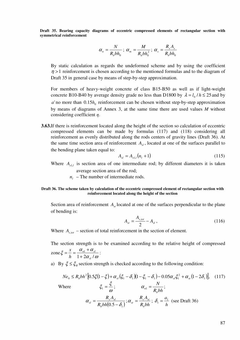
87
Draft 35. Bearing capacity diagrams of eccentric compressed elements of rectangular section with
symmetrical reinforcement
0bhR
N
b
n =α ; 2
0bhR
M
b
m =α ; 0bhR
AR
b
ss
s =α
By static calculation as regards the undeformed scheme and by using the coefficient
1>η reinforcement is chosen according to the mentioned formulas and to the diagram of
Draft 35 in general case by means of step-by-step approximation. For members of heavy-weight concrete of class B15-B50 as well as if light-weight
concrete B10-B40 by average density grade no less than D1800 by 25/0 ≤= hlλ and by
'a no more than 015.0 h reinforcement can be chosen without step-by-step approximation
by means of diagrams of Annex 3, at the same time there are used values M without considering coefficient η.
3.63.If there is reinforcement located along the height of the section so calculation of eccentric compressed elements can be made by formulas (117) and (118) considering all reinforcement as evenly distributed along the rods centers of gravity lines (Draft 36). At
the same time section area of reinforcement slA , located at one of the surfaces parallel to
the bending plane taken equal to:
( )1,1 += llssl nAA (115)
Where lsA ,1 is section area of one intermediate rod; by different diameters it is taken
average section area of the rod;
ln – The number of intermediate rods.
Draft 36. The scheme taken by calculation of the eccentric compressed element of rectangular section with
reinforcement located along the height of the section
Section area of reinforcement stA located at one of the surfaces perpendicular to the plane
of bending is:
sl
tots
st AA
A −=2
,, (116)
Where totsA , – section of total reinforcement in the section of element.
The section strength is to be examined according to the relative height of compressed
zoneωα
ααξ
/21
1
sl
sln
h
x
+
+== :
a) By Rξξ ≤ section strength is checked according to the following condition:
( ) ( )( ) ( )[ ]1
2
11111
2
0 2105.0115.0 δαξαδξδξαξξ −+−−−−+−≤ stslslbbhRNe , (117)
Where ω
ξξ =1 ;
bhR
N
b
n =1α ;
( )15.0 δα
−=
bhR
AR
b
sls
sl ;bhR
AR
b
sts
st =α ; h
a11 =δ (see Draft 36)

88
b) By Rξξ > section strength is checked according to the following condition:
nRna
nna
mbt RbhRNeαα
ααα
−
−≤ 12
0 , (118)
Where bhR
AR
b
totss
na
,1+=α – relative value of longitudinal force by even compression of
the whole section;
nRmR αα , – Relative values of a bending moment and of longitudinal
force by compression zone height hRξ :
( ) ( )( ) ( )1
2
11111 2105.0115.0 δαξαδξδξαξξα −+−−−−+−= stRslRRslRRmR ;
( )12 1 −+= RslRnR ξαξα ;
ω
ξξ R
R =1 ; ωξ ,R – see table 18 and 19.
Eccentricity of longitudinal force 0e is determined considering the element deflection
according to Items 3.54-3.56.
Note. By location of reinforcement within end quarters of height 12ah − (see Draft 36) the calculation is
made in compliance with Items 3.61 and 3.62 considering reinforcement S and S’ as concentrated along their centers of gravity.
3.64. Calculation of compressed elements made of heavy-weight concrete B15-B40 or of
light-weight concrete B12.5-B30 and by average density grade no less than D1800 as regards longitudinal force applied with the eccentricity taken according to item 3.50
equal to accidental eccentricity 30/hea = by hl 200 ≤ can be made according to the
following condition:
( )totsscb ARARN ,+≤ ϕ , (119)
Where φ is the coefficient determined by the following formula:
( ) sbsbb αϕϕϕϕ −+= 2 (120)
But it’s taken no more than sbϕ
Here sbb ϕϕ , are coefficients taken according to Tables 26 and 27;
AR
AR
b
totss
s
,=α ;
totsA , – See Item 3.63;
By 5.0>sα it is possible to take sbϕϕ = without using formula (120).
Table 26
Coefficient bϕ by hl /0 Concrete
N
N l
6 8 10 12 14 16 18 20
Heavy-weight 0 0.5 1.0
0.93 0.92 0.92
0.92 0.91 0.91
0.91 0.90 0.89
0.90 0.89 0.86
0.89 0.86 0.82
0.88 0.82 0.76
0.86 0.78 0.69
0.84 0.72 0.61

89
Light-weight 0 0.5 1.0
0.92 0.92 0.91
0.91 0.90 0.90
0.90 0.88 0.86
0.88 0.84 0.80
0.86 0.79 0.71
0.82 0.72 0.62
0.77 0.64 0.54
0.72 0.55 0.45
Table 27
Coefficient bϕ by hl /0 Concrete
N
N l
6 8 10 12 14 16 18 20
A. By haa 15.0'<= and if there are no intermediate rods (see a sketch) or by section area of these rods less
than 3/,totsA
Heavy-weight 0 0.5 1.0
0.93 0.92 0.92
0.92 0.92 0.91
0.91 0.91 0.90
0.90 0.89 0.89
0.89 0.88 0.87
0.88 0.86 0.84
0.86 0.83 0.79
0.84 0.79 0.74
Light-weight 0. 0.5 1.0
0.92 0.92 0.92
0.92 0.91 0.91
0.91 0.90 0.90
0.89 0.88 0.88
0.88 0.86 0.85
0.85 0.83 0.80
0.82 0.77 0.74
0.77 0.71 0.67
B. By haah 15.0'25.0 ≥=> or by section are of no intermediate rods (see a sketch) is equal or more than
3/,totsA independently on value a
Heavy-weight 0 0.5 1.0
0.92 0.92 0.92
0.92 0.91 0.91
0.91 0.90 0.89
0.89 0.88 0.86
0.87 0.85 0.82
0.85 0.81 0.77
0.82 0.76 0.70
0.79 0.71 0.63
Light-weight 0. 0.5 1.0
0.92 0.92 0.91
0.91 0.91 0.90
0.90 0.89 0.88
0.88 0.86 0.84
0.85 0.81 0.76
0.81 0.73 0.68
0.76 0.65 0.60
0.69 0.57 0.52
Symbols in Table 26 and 27:
lN – Longitudinal force of dead loads and long-term loads:
N – Longitudinal force of all loads
Sketch
1 – Considered plane;
2 – Intermediate rods.
RECTANGULAR SECTIONS WITN ASYMMETRICAL REINFORCEMENT 3.65.The strength of rectangular sections with asymmetrical reinforcement concentrated at the
most compressed and tensile (the least compressed) surfaces of the element is calculated according to Item 3.61, at the same time formulas (107), (109) and (110) have the following form:
bR
ARARNx
b
sscss
'−+= ; (107a)
( ) ( ) ( )sR
ssRssRn
αξ
ααξααξαξ
21
1 ''
+−
−+++−= ; (109a)
ωαψααψαααψα
ξ sc
nscsnscs +
−++
−+−=
2''
22; (110a)
Where0
''
bhR
AR
b
ssc
s =α
3.66. Areas of sections of compressed and tensile reinforcement corresponding to minimum of their sum is determined by following formulas: For elements made of concrete B30 and lower:

90
( )0
'
4.0
0
2
0' ≥−
−=
ahR
bhRNeA
sc
b
s ; (121)
'055.0s
s
b
s AR
NbhRA +
−= ; (122)
For elements of concrete more than B30:
( )0
'0
2
0' ≥−
−=
ahR
bhRNeA
sc
bR
s
α; (123)
'0s
s
bR
s AR
NbhRA +
−=
ξ (124)
Where RR ξα , are determined according to Tables 18 and 19 and are taken no more than
0.4 and 0.55.
By negative value sA determined by formula (122) and (124) it is taken minimum section
area of reinforcement S according to constructive requirements but no less than the following value:
( ) ( )( )'
'2/'
0
0min,
ahR
ahbhReahNA
sc
b
s−
−−−−= ; (125)
And the section area of reinforcement S’ is determined in the following manner:
- by negative value of min,sA – by the following formula:
( ) ( ) ( )
sc
bbbb
sR
beRbhRNNbaRNbaRNA
22'' 0
2
'+−−−−−
= , (126)
- by positive value of min,sA – by the following formula:
min,
'
s
sc
b
s AR
bhRNA −
−= ; (127)
If accepted section area of compressed reinforcement '
, factsA is more than the value
calculated by formula (121) or (123) (for example by negative value '
sA ) so section area
of tensile reinforcement can be decreased according to the following formula:
s
factsscb
sR
ARNbhRA
',0 +−
=ξ
; (128)
Where ξ is determined according to table 20 in compliance with the following value:
( )2
0
0', '
bhR
ahARNe
b
factssc
m
−−=α ; (129)
If there is no compressed reinforcement or it’s not considered in the calculation so section area of tensile reinforcement is always determined by formula (128) but at the same time
it is necessary to meet the requirement Rm αα < .
I-SECTIONS WITH SYMMETRICAL REINFORCEMENT
3.67. The strength of I-sections with symmetrical reinforcement concentrated in flanges (see
Draft 37) is made in the following manner. Draft 37. Loads scheme in the cross-I-section of eccentric compressed element

91
If the following condition is met (that is the border of compressed zone lies in the flange) so
the calculation is made as for a rectangular section '
fb wide in compliance with Item 3.61:
''
ffb hbRN ≤ (130)
If condition (130) is not met (that is the border of compressed zone goes in the rib) so the
calculation is made according to the compressed zone heightbR
ARNx
b
ovb−= :
a) by 0hx Rξ≤ section area is examined according to the following condition:
( ) ( ) ( )'2/2/ 0
''
00 ahARhhARxhbxRNe sscfovbb −+−+−≤ (131)
b) by 0hx Rξ> section area is examined according to condition (131) determining the height
of compressed zone by the following formula:
+
−+++
−++−= ωαψ
αααψααααψαsc
novscsnovscshx
2
022
(132)
Where0bhR
AR
b
ss
s =α ; 0bhR
N
b
n =α ; 0bh
Aov
ov =α
ωξψ ,, Rc – See table 18 and 19
ovA – Area of compressed flange overhangs equal to ( ) ffov hbbA −= '
If value x determined by formula (132) is more than fhh − (that is the border of compressed
zone goes along the least compressed flange) it is possible to consider the increase of the
bearing capacity due to the less compressed flange. In that case (if ff bb =' ) the calculation is
made by formulas (131) and (132) replacing fb by '
fb and '
fh by )( '
ff hhh −+ taking
( )( )fffov hhhbbA −−−−= ' .
Note. By variable height of the flange overhangs values fh and '
fh are taken equal to the average height of
overhangs.
3.68.Required quantity of symmetrical reinforcement of I-sections is determined in the following manner.
If condition (130) is met so reinforcement is chosen as for rectangular sections '
fb wide
according to Item 3.62. If condition (130) is not met so reinforcement is chosen according to relative height of compressed zone ξ:
ovn ααξ −= (133)
a) by Rξξ ≤
( )δ
αξξα
−
−−−==
1
2/1 ,10' ovmm
s
b
ssR
bhRAA (134)
b) by Rξξ >
( )δ
αξξα
−
−−−==
1
2/1 ,1110' ovmm
s
b
ssR
bhRAA (135)

92
Where relative height of compressed zone 01 / hx=ξ is determine according to formula
(132) by:
( )δ
αξξαα
−
−−−=
1
1 ,1 ovmm
s (136)
In formulas (133)–(136):
ovn αα , – See Item 3.67;
2
0
1,bhR
Ne
b
m =α ; 0/' ha=δ ;
( )0
'
, /5.01 hh fovovm −= αα .
RING CROSS-SECTIONS 3.69.The strength of ring cross-sections (Draft 38) by the ratio of inner and outer radius
5.0/ 21 ≥rr and reinforcement distributed along the circle (by no less than 6 longitudinal
rods) is calculated in the following manner according to relative area of compressed zone
of concrete cirξ :
totssb
totss
cirARAR
ARN
,
,
7.2+
+=ξ (137)
a) by 6.015 << cirξ – according to the following condition:
( ) ( )( )circirstotss
cir
stotssmb rARrARArRNe ξξπ
πξ3.12.07.11
sin,,0 +−++≤ (138)
b) by 15.0≤cirξ – according to the following condition
( ) stotss
cir
stotssmb rARrARArRNe ,1
,0 29.0sin
++≤π
πξ (139)
Where totssb
totss
cirARAR
ARN
,
,
1
75.0
+
+=ξ (140)
c) By 6.0≥cirξ – according to the following condition
( )π
πξ 2,0
sin cir
stotssmb rARArRNe +≤ (141)
Where totssb
cirARAR
N
,
2+
=ξ (142)
In formulas (137)–(142):
totsA , – Section area of total longitudinal reinforcement;
221 rr
rm
+= ;
sr – Circle radius going through the center of gravity of considered reinforcement.
Eccentricity of longitudinal reinforcement 0e is determined considering the element
deflection according to Items 3.54–3.56.
Draft 38. The scheme taken by calculation of the ring cross-section of eccentric compressed element

93
3.70.It is possible to check the strength and to determine required quantity of reinforcement of
ring sections mentioned in Item 3.69 by ms rr ≈ by means of diagrams of Draft 39 using
the following formulas:
ArRNe mbmα≤0 (143)
s
b
stotsR
ARA α=, (144)
AR
N
b
n =α ; mb
mArR
Ne0=α ;AR
AR
b
totss
s
,=α
Where values mα and sα are determined in compliance with the diagram according to
values AR
AR
b
totss
s
,=α and
mb
mArR
Ne0=α as well asAR
N
b
n =α . At the same time eccentricity
0e is determined considering the deflection of the element according to Items 3.54–3.56.
Draft 39. Bearing capacity diagrams of eccentric compressed elements of ring-section
ROUND SECTIONS 3.71.The strength of round sections (Draft 40) with reinforcement distributed along the circle
(no less than 60 longitudinal rods) by concrete class no less than B30 is checked according to the following condition:
s
cir
totss
cir
b rARArRNe
++≤ ϕ
π
πξ
π
πξ sinsin
3
2,
3
0 (145)
Where r – radius of the cross section;
cirξ – Relative area of the compressed concrete zone determined in the following
manner: If the following condition is met:
totssb ARARN ,645.077.0 +≤ (146)
According to the following equation:
totssb
cir
btotss
cirARAR
ARARN
,
,2
2sin
+
++= π
πξ
ξ ; (147)
If equation (146) is not met so it’s determined according to the following equation:
totssb
cir
b
cirARAR
ARN
,
2
2sin
+
+= π
πξ
ξ ; (148)
ϕ – Coefficient considering the work of tensile reinforcement and taken equal to; if
condition (146) is met ( ) circir ξξϕ 55.116.1 −= but no more than one; if condition
(146) is not met so 0=ϕ ;
totsA , – Section area of the total longitudinal reinforcement;
sr – Circle radius going through the center of gravity of longitudinal reinforcing rods.
Eccentricity of longitudinal force 0e is determined considering the deflection of the
element according to Items 3.54–3.56.
Draft 40. The scheme taken by the calculation of the round section of the eccentric compressed element

94
3.72.It is possible to check the strength and to determine required quantity of reinforcement of round sections mentioned in Item 3.71 by means of diagrams of Draft 41 using the following formulas:
ArRNe bmα≤0 ; (149)
s
b
stotsR
ARA α=, , (150)
Where values mα and sα are determined by Draft 41 according to values AR
AR
b
totss
s
,=α
andArR
Ne
b
m
0=α as well asAR
N
b
n =α . At the same time eccentricity 0e is determined
considering the deflection of the element according to Items 3.54–3.56.
Draft 41. Bearing capacity diagrams of eccentric compressed elements of round section
CALCULATION OF ELEMENTS WORKING IN BIAXIAL ECCENTRIC COMPRESSION 3.73.Calculation of normal sections of elements working in biaxial eccentric compression is
made in general case according to Item 3.76 determining location of the straight line which bounds the compressed zone by means of step-by-step approximation.
3.74.Calculation of elements of rectangular section with symmetrical reinforcement as regards
biaxial compression can be made by means of diagrams of Draft 42. Draft 42. Diagrams of bearing capacity of rectangular section elements with symmetrical reinforcement
working in biaxial eccentric compression
a – by 2.0=sα ; b – by 4.0=sα ; c – by 6.0=sα ; d – by 0.1=sα (wherebhR
AR
b
totss
s
,=α )
Section strength is considered to be provided if points with coordinates 0/ xx MM and 0/ yy MM on the diagram corresponding to parameter sα are located inside of the part
bounded by a curve corresponding to parameter 1nα and by axes of coordinates.
Values xM and yM are represented by bending moments caused by external loads
relating to the center of gravity of the section and acting in symmetry planes x and y. Influence of the element deflection is considered by means of multiplying of moments
xM and yM by coefficients xη and yη determined for planes x and y according to Item
3.54 by the longitudinal force N.
Values 0
xM and 0
yM are represented by limit bending moments which can be taken by
the section in symmetry planes x and y considering longitudinal force N applied in the center of gravity of the section.
Values of limit moments 0
xM and 0
yM are represented by right parts of equations (117)
and (118). At the same time discretely located reinforcement rods are replaced by distributed reinforcement.

95
( ) ( )β
β
+−−++=
121 ,1,10,1 ysxssxxssx AAAnAA ; (151)
sx
tots
sy AA
A −=2
, (152)
Where sysx AA , – area of reinforcement located at surfaces normal to symmetry axes x and
y (Draft 43);
ysxs AA ,1,1 , – Area of each intermediate rod located at surfaces normal to symmetry
axes x and y;
xn – Number of intermediate rods with the area xsA ,1 located along one side
of the section;
0sA – Angle rod area;
x
y
y
x
h
h
M
M=β ;
yx hh , – Section height by eccentric compression in planes x and y;
totsA , – Section area of total longitudinal reinforcement.
Parameters sα and 1nα are determined by following formulas:
bhR
AR
b
totss
s
,=α ;
bhR
N
b
n =1α
Draft 43. Location of reinforcement in rectangular section by calculation as regards biaxial eccentric
compression
a – actual; b – design
3.75.Calculation of elements of symmetrical I-section by 53/ −=bb f and 25.015.0/ −=hh f
with symmetrical reinforcement located in flanges of the section as regards biaxial compression can be made by means of diagrams of bearing capacity given on Draft 44.
Draft 44. Bearing capacity of elements of symmetrical I-section working in biaxial eccentric compression
a – by 2.0=sα ; b – by 4.0=sα ; c – by 0.1=sα ; d – by 4.1=sα (wherebhR
AR
b
totss
s
,=α ); e – by
8.1=sα ; f – by 8.2=sα (wherebhR
AR
b
totss
s
,=α )
The calculation is made similar to the calculation given in Item 3.74 for elements of rectangular section.
Taken by the section in the symmetry axis x going in the rib limit moment 0
xM
represented by the right part of condition (131) decreased by ( ) 2/'0 ahN − ; limit moment 0
yM can be determined as for rectangular section made up of two flanges according to
Item 3.63.
GENERAL CASE OF CALCULATION OF NORMAL SECTIONS OF ECCENTRIC COMPRESSED ELEMENTS (BY ANY SECTIONS, EXTERNAL FORCES AND BY ANY REINFORCEMENT)
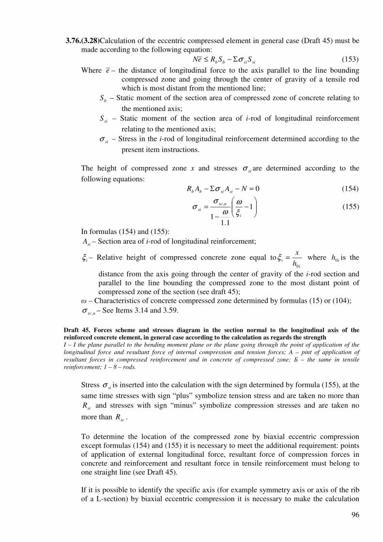
96
3.76.(3.28)Calculation of the eccentric compressed element in general case (Draft 45) must be made according to the following equation:
sisibb SSReN σΣ−≤ (153)
Where e – the distance of longitudinal force to the axis parallel to the line bounding compressed zone and going through the center of gravity of a tensile rod which is most distant from the mentioned line;
bS – Static moment of the section area of compressed zone of concrete relating to
the mentioned axis;
siS – Static moment of the section area of i-rod of longitudinal reinforcement
relating to the mentioned axis;
siσ – Stress in the i-rod of longitudinal reinforcement determined according to the
present item instructions.
The height of compressed zone x and stresses siσ are determined according to the
following equations:
0=−Σ− NAAR sisibb σ (154)
−
−
= 1
1.11
,
i
usc
siξ
ωω
σσ (155)
In formulas (154) and (155):
siA – Section area of i-rod of longitudinal reinforcement;
iξ – Relative height of compressed concrete zone equal toi
ih
x
0
=ξ where ih0 is the
distance from the axis going through the center of gravity of the i-rod section and parallel to the line bounding the compressed zone to the most distant point of compressed zone of the section (see draft 45);
ω – Characteristics of concrete compressed zone determined by formulas (15) or (104);
usc,σ – See Items 3.14 and 3.59.
Draft 45. Forces scheme and stresses diagram in the section normal to the longitudinal axis of the
reinforced concrete element, in general case according to the calculation as regards the strength
I – I the plane parallel to the bending moment plane or the plane going through the point of application of the
longitudinal force and resultant force of internal compression and tension forces; A – pint of application of
resultant forces in compressed reinforcement and in concrete of compressed zone; Б – the same in tensile
reinforcement; 1 – 8 – rods.
Stress siσ is inserted into the calculation with the sign determined by formula (155), at the
same time stresses with sign “plus” symbolize tension stress and are taken no more than
siR and stresses with sign “minus” symbolize compression stresses and are taken no
more than scR .
To determine the location of the compressed zone by biaxial eccentric compression except formulas (154) and (155) it is necessary to meet the additional requirement: points of application of external longitudinal force, resultant force of compression forces in concrete and reinforcement and resultant force in tensile reinforcement must belong to one straight line (see Draft 45). If it is possible to identify the specific axis (for example symmetry axis or axis of the rib of a L-section) by biaxial eccentric compression it is necessary to make the calculation

97
according to two conditions: (153) determining values e , bS and siS relating to axis x
going through the center of gravity of the most tensile rod parallel to the mentioned above specific axis and according to condition (153) determining values e ,
bS and siS relating to axis y which crosses axis x at right angle in the center of the most
tensile rod. At the same time the location of the straight line bounding the compressed zone is chosen by means of step-by-step approximation according to equations (154) and (155) taking the angle of slope of this line θ constant and equal to the angle of slope of the neutral axis determined as for elastic material. Section strength will be provided only if condition (153) is met relating to both axes (x and y). If equation (153) is not met during all examinations so the strength of the section is not provided and it is necessary to increase reinforcement, dimensions of the section or to increase concrete class. If the condition is met only relating to one axis so it is necessary to determine the shapes of compressed zone one more time by different angle θ and to make similar calculation one more time.
EXAMPLES OF CALCULATION
RECTANGULAR SECTIONS WITH SYMMETRICAL REINFORCEMENT Example 24. Given: a column with the frame work, section b = 400 mm, h = 500 mm,
40'== aa mm; heavy-weight concrete B25 ( 4107.2 ⋅=bE MPa); reinforcement A-III
( 365== scs RR MPa; 5102 ⋅=sE MPa); its section area is 1232' == ss AA mm2 (2Ø28);
longitudinal forces and bending moments: from dead loads and long-term loads 650=lN kN,
140=lM kN·m; from wind load 50=shN kN, 73=shM kN·m; design length of the
column 60 =l m.
It is required to check the strength of the column section.
Calculation: 460405000 =−=h mm. As there are forces from the short-term loads (wind
load) so the calculation is made according to case “a” in compliance with Item 3.1. Forces from wind load are equal to:
70050650 =+=N kN; 21373140 =+=M kN·m
Let’s determine moments of external forces relating to tensile reinforcement IM and
IIM calculated considering and without consideration a short-term load (wind load):
3602
04.046.0700213
2
'01 =
−+=
−+==
ahNMMM II kN·m
5.2762
04.046.0560140
2
'01 =
−+=
−+==
ahNMMM lllI kN·m
As 29536082.082.0 =⋅=IIM kN·m so the calculation is made only according to case “b” (see
Item 3.1) that is as regards all loads taking 16=bR MPa (by 1.12 =bγ ).
As 10125.0/6/0 >==hl so the calculation is made considering the column deflection
according to Item 3.54, calculating crN by formula (93).
For that we determine:

98
77.1360
5.276111
1
1 =+=+=M
M l
l βϕ
[Here 0.1=β for heavy-weight concrete (see Table 16)];
0913.0107.2500400
102123224
5'
=⋅⋅⋅
⋅⋅⋅=
+=
b
sss
E
E
bh
AAµα ;
30410700
102133
6
0 =⋅
⋅==
M
Ne mm > 30/hea =
So that means accidental eccentricity is not to be taken into account.
As 22.0161201.05.001.001.05.0608.0500
304 0min,
0 =⋅⋅−=−−=>== be Rh
l
h
eδ so we
take 608.00
h
ee =δ .
Coefficient η is to be determined by formula (91): Value е is:
.55,05492
40460115,1304
2
00 мmm
ahee ≅=
−+⋅=
′−+= η
Let’s determine the height of compressed zone х by formula (107): mm.
ξR = 0.55 (See Table 18).
As х = 109,4 mm < ξRh0 = 0,55 · 460 = 253 mm so section strength is to be checked according to condition (108):
( ) ( ) ( )
( ) ,38555,07006,472106,47240460
12323654,1095,04604,109400165,0
6
00
mkNNemkNmmN
ahARxhbxR sscb
⋅=⋅=>⋅=⋅⋅=−×
×⋅+⋅−⋅⋅=′−′+−
т. е. прочность сечения обеспечена. Example 25. Given: section of the element with dimensions b = 400 mm, h = 500 mm; a = a' =
= 40 mm; heavy-weight concrete В25 (Eb = 2,7 · 104 MPa); symmetrical reinforcement A-III (Rs =
= Rsc = 365 MPa; Es = 2 · 105 MPa); longitudinal forces and bending moments: from dead loads and long-term loads Nl = 600 kN, Ml = 170 kN·m; from wind load Nsh = 200 kN, Мsh = 110 kN·m; design length l0 = 8 m.
It is required to determine section area of reinforcement. Calculation: h0 = 500 – 40 = 460 mm. As there are wind load forces so let’s check condition
(1). For that we determine: kN·m; kN·m; kN; kN·m. As 0,82 MII = 0,82 · 448 = 368 kN·m > MI = 296 kN·m so the calculation is made only
according to case „b", that is as regards all loads, taking Rb = 16 MPa (by γb2 = 1,1). As l0/h = 8000/500 = 16 > 10 so the calculation is made considering the element deflection
according to Item 3.54, calculating Ncr by formula (93). For that we determine:
[β = 1,0 – See Table 16];
30/35010800
102803
6
0 hemmN
Me a =>=
⋅
⋅==
(See Item 3.50)

99
As е0/h = 350/500 = 0,7 > δe,min = 0,5 – 0,01 – 0,01Rb, so we take δe = = 0,7.
On the first approximation we take µ = 0,01, = 7,4, So
( )
( ) kNH
h
ah
hl
bhEN
l
eb
cr
33721033720522,00477,01075,33500
404604,701,0
66,13
1,07,01,0
11,0
16
500400107,26,1
3
1,01,0
11,0
/
6,1
36
2
2
42
0
2
0
=⋅=+⋅=
−⋅+
⋅
++
×
×⋅⋅⋅⋅
=
′−+
+
+= αµ
ϕ
δ
Coefficient η is: Considering the element deflection value е is: mm. Required reinforcement we determine according to Item 3.62. Let’s determine the following values:
By Table 18 we find ξR = 0,55.
As αn < ξR , so value Аs = is to be determined by Formula (112): ( )
( ),1413
087,01
2/272,01272,0395,0
365
46040016
1
2/1
2
10
mm
R
bhRAA nnm
s
b
ss
=−
−−⋅⋅=
=−
−−=′=
δ
ααα
From which
As the present reinforcement is more than reinforcement taken during determination of Ncr (µ =
= 0,01) so value Аs = 1413 mm2 is determined „on the safe side" and it can be decreased if value µ. is specified more exact
We take µ = (0,01 + 0,014)/2 = 0,012 and determine value Аs = :
[
;3724103724500
40460
4,7012,00477,01075,33
3
2
6
kNН
N cr
=⋅=
−×
×⋅+⋅=
mm; mm2.
Finally we take As = = 1362 mm2 (2 ∅ 25 + 1 ∅ 22).
Example 26. According to Example 25 data it is necessary to determine reinforcement area,
using diagrams of Annex 3. Calculation. In compliance with Example 25: N = 800 kN; М = 280 kN·m; = 16; = 0,66.
Let’s determine values αn и αm:
By diagram б of Annex 3 by αn = 0,272, αm = 0,207 and λ = 15 we find αs = 0,16.
By diagram в of Annex 3 by αn = 0,272, αm = 0,207 and λ = 20 we find αs = 0,2.

100
Value αs corresponding to λ = 16 is to be determined by means of linear interpolation: So reinforcement area is: mm2.
We take Аs = = 1362 mm2 (2 ∅ 25 + 1 ∅ 22). Example 27. Given: a column with the multistory framework with the section dimensions b = = 400 mm, h = 500 mm; a = а’ = 40 mm; heavy-weight concrete В25 (Eb = 2,7 · 104 MPa); symmetrical reinforcement А-III (Rs = Rsc = 365 MPa; Еs = 2 · 105 MPa); longitudinal forces and bending moments in the support section of the column: from dead loads and long-term loads on the floors Nl = 2200 kN, Ml = 259 kN·m; from wind loads Nsh = 0, Msh = 53,4 kN·m; no short-term loads on the floor; design length of the column is l0 = 6 м. It is required to determine reinforcement area. Calculation. h0 = h – а = 500 – 40 = 460 mm. As there is the wind load force we determine condition (1). We determine: kN·m; kN; kN·m; kN·m. As 0,82 MII = 0,82 · 784,4 = 643 кН·м < MI = 721 kN·m so condition (1) is not met and we make the calculation twice: according to case „а" — as regards dead loads and long-term loads
by Rb = 13 MPa (that is by γb2 = 0,9) and according to case „b" — as regards all loads by Rb =
= 16 МПа (that is by γb2 = 1,1). The calculation is made for the support section. Calculation according to case „а". As l0/h = 6000/500 = 12 > 4 according to Item 3.54 so it is
necessary to consider the column deflection. But in compliance with Item 3.56 coefficient ηv for columns and multistorey frameworks taken for the moment Mv caused by loads on the floors is taken equal to 1,0 and moment Мh = Msh from wind loads is not considered in the
present calculation, that’s why design moment is М = Мv ηv = 259 kN·m. Design longitudinal force is N = Nl = 2200 kN, so = 118 mm > = 16,7 mm. We take e0 = 118 mm. By formula (111) we determine е = e0 + (h0 – a’)/2 = 118 + (460 – 40)/2 = 328 mm. Required reinforcement is to be determined according to Item 3.62. Let’s determine the following values:
By Table 18 we find ξR = 0,604.
As αn = 0.92 > ξR = 0,604 so value Аs = is to be determined by formula (113). For that we
calculate values αs and ξ by formulas (114) and (109):
( ) ( ).1304
087,01
2/772,01772,0656,0
365
46040013
1
2/1 210 mmR
bhRAA m
s
b
ss =−
−−⋅⋅=
−
−−=′=
δ
ξξα
Calculation by case „b". In compliance with Item 3.54 we determine coefficient η, taking reinforcement, calculated according to case „а", that is:
[β = 1,0 – See Table 16]; mm.
As e0/h = = 0,293 > δe,min = 0,5 – 0,01 l0/h – 0,01 Rb = 0,5 –0,01 · 12 – 0,01 · 16 = 0,22, we
take δe = е0/h = 0,293;

101
By formula (93) we determine Ncr:
( )
,108021500
40460096,0
92,13
1,0293,01,0
11,0
12
500400107,26,1
3
1,01,0
11,0
/
6,1
3
2
2
42
0
2
0
N
h
ah
hl
bhEN
l
eb
cr
⋅=
−×
+⋅
++
×
×⋅⋅⋅⋅
=
′−+
+
+= αµ
ϕ
δ
So coefficient η is:
According to Item 3.56 coefficient η = ηh = 1,38 is multiplied by the wind loads moment Мsh =
= M and coefficient ηv = 1,0, that’s why considering the element deflection the moment is equal to: kN·m. Required reinforcement we determine by Item 3.62 similar to the calculation according to case „а" taking Rb = 16 MPa: mm;
According to Table 18 we find ξR = 0,55.
As αn > ξR so we determine value Аs = by formula (113): So
( ) ( )
.13041228
087,01
2/675,01675,0586,0
365
46040016
1
2/1
22
10
mmмм
R
bhRAA m
s
b
ss
<=
=−
−−⋅⋅=
−
−−=′=
δ
ξξα
Finally we take As = = 1362 mm2 (2 ∅ 25 + 1 ∅ 22) >1304 mm2. Example 28. Given: the element section with dimensions b = 400 mm, h = 600 mm; heavy-
weight concrete В25 (Rb = 16 MPa by γb2 = 1,1; Eb = 2,7 · 104 MPa); reinforcement A-III (Rs
= Rsc = 365 MPa; Еs = 2 · 105 MPa) located in the section as it’s shown on Draft 46; longitudinal forces and bending moments: from all loads N = 500 kN, М = 500 kN·m; from dead loads and long-term loads Nl = 350 kN, Ml = 350 kN·m; design length l0 = 10 м. It is required to examine the section strength.
Черт. 46. For the calculation example 28
The calculation is to be made according to Item 3.63. Taking As1,l = 491 mm2 (∅ 25), ηl = 2
and As,tot = 6890 mm2 (8 ∅ 28 + 4 ∅ 25) we find reinforcement area Asl и Аst: mm2; mm2. According to Draft 46 we have a1 = 45 mm, so As l0/h = 10/0,6 = 16,7 > 10 the calculation is to be made considering the element deflection according to Item 3.54 determining value Ncr by formula (93). For that we determine:
[β = 1.0 (See Table 16)];

102
m.
As e0/h = = 1,67 > δe,min = 0,5 – 0,01 l0/h – 0,01 Rb, so we take δe = е0/h = 1,67.
Value µα we determine as for the section with reinforcement located along the height of the section in compliance with Item 3.54: So
( )
.527110527111,07,13
1,067,11,0
11,0
7,16
600400107,26,1
3
1,01,0
11,0
/
6,1
3
2
42
0
2
0
kNH
h
ah
hl
bhEN
l
eb
cr
=⋅=
+⋅
++
×
×⋅⋅⋅⋅
=
′−+
+
+== αµ
ϕ
δ
Coefficient η is: Let’s determine the following values:
According to Table 18 we find ω = 0,722 and ξR = 0,55.
As 0.24 < ξR = 0.55 so section strength is to be determined by formula (117):
( ) ( )( )[ ( )]( ) ( )[ ( )
( )] mkNNeмкНммН
bhR stslslb
⋅=⋅=>⋅=⋅⋅=⋅−+
+⋅⋅−−−×−+−⋅×
×⋅⋅=−+−−−−+−
552105,150068810688075,021187,0
332,0329,005,0075,0332,01075,0332,0329,024,0124,05,0
600400162105,0115,0
0
6
2
2
1
2
11111
2
η
δαξαδξδξαξξ
That is the section strength is provided. Example 29. Given: column section with dimensions b = 600 mm, h = 1500 mm; heavy-
weight concrete В30 (Rb = 19 MPa by γb2 = 1,1); reinforcement А-III (Rs = 365 MPa) located as it’s shown on Draft 47; longitudinal forces and bending moments determined according to the frame calculation as regards deformed scheme: from all loads N = 12 000 kN, М = 5000 kN·m; from dead loads and long-term loads Nl = 8500 kN, Мl = 2800 kN·m; design length of the column in the bending plane l0 = 18м, out of the bending plane l0 = 12 м; actual column length l = 12 m. It is required to examine the section strength.
Черт. 47. For the calculation example 29
The calculation in the bending plane is made according to Item 3.63.
Taking As1,l = 615, 8 mm2 (∅ 28), ηl = 5 and As,tot = 17 417 mm2 (14 ∅ 32 + 10 ∅ 28), we
find reinforcement area Аsl and Аst: Аsl = Аs1,l (ηl + 1) = 615, 8 (5 + 1) = 3695 mm2, mm2.
Center of gravity of reinforcement located at tensile surface (7 ∅ 32) is distant from this surface mm, So Let’s determine the following values:

103
From Table 18 we find ω = 0,698 and ξR = 0,523. As 0,584 > ξR = 0,523so section strength is to be checked by formula (118). For that we determine:
,5000541310541361,0372,1
702,0372,1
24,0150060019
6
212
mkNMмкНммН
bhRnRna
nna
mRb
⋅=>⋅=⋅⋅=−
−×
×⋅⋅⋅=−
−
αα
ααα
That is the section strength in the bending plane is provided. The calculation out of the bending plane. As design length out of the bending plane l0 = 12 m and ratio l0/b = 12/0,6 = 20 is more than ration l0/h = 18/1,5 = 12, corresponding to the column calculation in the bending plane according to 3.51, so it is necessary to calculate the column out of the bending plane taking eccentricity е0 equal to occasional eccentricity еa. At the same time we replace symbols h and b by b and h, that is we take the dimension of the section out of the bending plane h = 600 мм instead of the section height. As according to Item 3.50 the accidential eccentricity is equal to
600
00012
60020
30
600
30=≥===
lmm
hea
and l0 = 12 m ≤ 20h, so the calculation is made according
to Item 3.64.
Section area of intermediate rods located along the short sides is equal to As,int = 4826 мм2 (6 ∅ 32). As = 5800 mm2
> As,int = 4876 mm2 и а = 50 mm < 0,15h = 0,15 · 600 = 90 mm so we
use Table 27 in the calculation (Part А). According to Tables 26 and 27 by and we find ϕb =
0,674 and ϕsb = 0,77. Value
By formula (120) we determine coefficient ϕ: Let’s check condition (119):
( ) ( ) ,000125001741717365150060019746,0, kNNкНARAR totssb =>=⋅+⋅⋅=+ϕ
That is the section strength out of the bending plane is provided. Example 30. Given: a column with the section 400Х400 mm; design length is equal to the
actual length l = l0 = 6 m; heavy-weight concrete В25 (Rb = 13 MPa by γb2 = 0,9); longitudinal reinforcement A-III (Rsc = 365 MPa); centric applied forces: from dead loads and long-term loads Nl = 1800 kN; from short-term loads Nsh = 200 kN. It is required to determine section area of longitudinal reinforcement. Calculation: in compliance with Item 3.50the calculation is made considering occasional eccentricuty ea. As h/30 = 400/30 = 13,3 mm > = 10 mm so occasional eccentricity is taken equal to ea = h/30, so the calculation can be made according to Item 3.64, taking
20002001800 =+=+= shl NNN kN.
According to Tables 26 and 27 for heavy-weight concrete by Nl/N = 1800/2000 = 0,9, l0/h = =6000/400 = 15, supposing that there are no intermediate rods by а = а' < 0,15 h, we find
ϕb = 0,8 и ϕsb = 0,858.
Taking in the first approximation ϕ = ϕsb = 0,858 according to condition (119) we find:

104
.1025110208010233140040013858,0
102000 3333
, NARN
AR btotss ⋅=⋅−⋅=⋅⋅−⋅
=−=ϕ
So
As αs < 0,5 we specify value ϕ more exact calculating it by formula (120): In a similar manner we determine
.10377102080814,0
102000 333
, NAR totss ⋅=⋅−⋅
=
Calculated value RsAs,tot is more than the accepted in the first approximation value so we determine this value one more time:
.10360102080821,0
102000 333
, NAR totss ⋅=⋅−⋅
=
As determined value RsAs,tot is close to the value accepted in the second approximation so total area of reinforcement section is taken equal to: mm2.
Finally we take As,tot = 1018 mm2 (4 ∅ 18).
RECTANGULAR SECTIONS WITH ASYMETRICAL REINFORCEMENT Example 31. Given: element section with dimensions b = 400 mm, h = 500 mm; a = a' = 40
mm; heavy-weight concrete B25 (Rb = 13 MPa by γb2 = 0,9; Eb = 2,7 · 104); reinforcement A-III (Rs = Rsc = 365 MPa); longitudinal force N = 800 kN; its eccentricity relating to the center of gravity of concrete section е0 = 500 мм; design length l0 = 4,8 m. It is required to determine areas of reinforcement section S and S’. Calculation. h0 = 500 – 40 = 460 mm. As 4 < l0/h = 4,8/0,5 = 9,6 < 10so the calculaiton is made considering the element deflection according to Item 3.54. At the same time supposing
that µ ≤ 0,025we determine value Ncr by a simplified formula:
( ).9110109110
6,9
500400107,215,0
/15,0 3
2
4
2
0
kNНhl
AEN
b
cr =⋅=⋅⋅⋅
==
Coefficient η is to be determined by formula (91): Value e considering the element deflection: mm. Required section area of reinforcement S’ and S we determine by formulas (121) and (122):
( ) ( );01085
40460365
460400134,0758108004,0 223
0
20 >=
−
⋅⋅⋅−⋅⋅=
′−
−=′ mm
ahR
bhRNeA
sc
b
s
.24981085365
108004604001355,055,0 23
0 mmAR
NbhRA s
s
b
s =+⋅−⋅⋅⋅
=′+−
=
As 0,018 < 0,025 so values Аs and are not to be specified more exact.
We take = 1232 mm2 (2 ∅ 28), Аs = 2627 mm2 (2 ∅ 32 + 1 ∅ 36). ELEMENTS WITH CONFINEMENT REINFORCEMENT Example 32. Given: a column of a bracing framework with the section dimensions and location of reinforcement according to Draft 48; heavy-weight concrete В40 (Rb = 20 MPa by
γb2 = 0,9; Rb,ser = 29 MPa; Eb = 3,25 · 104 MPa); longitudinal reinforcement A-VI; confinement reinforcement meshes of rods A-III, diameter 10 mm (Rs,xy = 365 MPa), located with spacing
s = 130 mm along the whole length of the column; longitudinal force by γf > 1,0: from all loads

105
N = 6600 kN, from dead loads and long-term loads Nl = 4620 kN; the same by γf = 1,0: N = 5500 kN and Nl = 3850 kN; primary eccentricity of longitudinal force e0 = ea = 13,3 mm; design length of the column l0 = 3,6 m. It is required to examine the strength of the column. Draft. 48. For the calculation example 32
Calculation. Let’s check the section strength within the meshes contours considering confinement reinforcement according to Item 3.57. Design dimensions of the section
350== efef bh mm. As l0/hef = 3600/350 = 10,3 < 16 so confinement reinforcement can be
considered in the calculation; at the same time it is necessary to consider the column deflection in compliance with Items 3.54 and 3.58 as l0/hef > 4. Taking l0/cef = l0/hef = 10,3 and h = hef = 350 mm we get
Therefore we take δe = δe,min = 0,297. As intermediate rods of confinement reinforcement are located in end quarters of the distance between end rods equal to h –2a1 = 350 – 2 · 22 = 306 mm [58 mm < = 76,5 mm (see Draft 48)] so according to the note to Item 3.63 we take reinforcement S and S’ as concentrated along the lines of their center of gravity. Then considering that all rods have the same diameter we have: mm; mm.
Coefficient ϕl is to be determined by formula (94) taking β = 1,0 (see Table 16) and Critical force Ncr is to be determined by formula (93), taking
mm2 (6 ∅ 25),
and multiplying the calculated value by coefficient ϕ1 = 0,25 + 0,05 = 0,25 + 0,05 · 10,3 = =0,764:
( )
.900101090010764,0350
41309281,0
7,13
1,0297,01,0
11,0
3,10
3503501025,36,1
3
1,01,0
11,0
/
6,1
3
2
2
4
1
2
0
2
0
kNН
h
ah
hl
bhEN
l
eb
cr
=⋅=×
−+
⋅
++
×
×⋅⋅⋅⋅
=
′−+
+
+= ϕαµ
ϕ
δ
Coefficient η is equal to: So in compliance with formula (111), mm. Let’s determine prism strength Rb,red according to Item 3.57.
Taking Аsx = Аsy = 78,5 mm2 (∅ 10), nx = ny = 5, lx = ly = 350 mm and Aef = hefbef = 350 · 350= = 122 500 mm2 (see Draft 48) we determine coefficient so MPa As there is used high-strength reinforcement A-VI so design resistance of reinforcement against compression is to be determined according to Item 3.59: mm2;

106
We take θ = 1,6.
From Table 25 λ1 = 2,04, λ2 = 0,77, Rsc = 500 MPa, Rs = 815 MPa, so
MPaRМПаRR sscredsc 81574277,054,01
04,254,01500
1
1
23
13, =<=
⋅+
⋅+=
+
+=
λδ
λδ
Section strength is to be examined according to condition (108), determining the height of
compressed zone х = ξh0 by formula(110а).
For that we determine value ω by formula (104). As 10µxy = 10 · 0,0173 = 0,173 > 0,15, we
take δ2 = 0,15, then ω = 0,85 – 0,008 Rb + δ2 = 0,85 – 0,008 · 20 + 0,15 = 0,84 ≤ 0,9.
According to Items 3.61 and 3.65 we determine required coefficients αn, αs, and ψc, taking Rb
= Rb,red = 34,3 MPa; σsc,u = 380 + 1000 δ3 = 380 + 1000 · 0,54 = 920 MPa < 1200 MPa иand Rsc = Rsc,red = 742 MPa:
;1037103093503,34 3
0 NbhRb ⋅=⋅⋅=
So
Value ξR with replacing Rs by 0,8Rs is:
that means it was necessary to use formula (110a); mm;
( ) ( ) ( )
( ) ,1109168,06600105,1154413092945742
2845,03092843503,345,0
6
00
mkNNeмН
ahARxhbxR sscb
⋅=⋅=>⋅⋅=−⋅+
+⋅−⋅⋅=′−′+−
that is section strength is provided. Let’s examine resistance to strength of the column protection layer by means of similar
calculation as regards the force N = 5500 kN (by γf = 1,0) taking Rb = Rb,ser = 29 MPa, Rs =
=Rs,ser = 980 МПа, Rsc = 400 МПа, σsc,u = 400 МПа, ω = 0,85 – 0,006 Rb,ser = 0,85 – 0,006 · 29 = 0,679 according to Item 3.60 and considering total section of the column, that means b = h =
=400 mm, a = a′ = 41 + 25 = 66 mm, h0 = 400 – 66 = 334 mm. Critical force Ncr is to be determined by formula (93) taking l0/h = 3600/400 = 9, e0/h =
=13,3/400 = 0,033, δe,min = 0,5 – 0,01 – 0,008 Rb,ser = 0,5 – 0,01 · 9 – 0,008 · 29 = 0,178 >
e0/h, that means δe = δe,min = 0,178.
During determination of coefficient ϕl we consider longitudinal forces N and Nl by γf = 1.0, that means
so ϕl = 1 + 0,7 = 1,7;

107
( )
.900191090019
400
66334215,0
7,13
1,0178,01,0
11,0
9
4004001025,36,1
3
1,01,0
11,0
/
6,1
3
2
2
4
2
0
2
0
ђнH
h
ah
hl
bhEN
l
eb
cr
=⋅⋅=
=
−+
⋅
++⋅⋅⋅⋅
=
=
′−+
++
= µαϕ
δ
Coefficient η is: mm. Let’s make a calculation similar to the calculation as regards the strength:
;103880340029 3
0 NbhRb ⋅=⋅⋅=
mm;
( ) ( )( ) ( )
,8381524,05500
8,957108,957
663342945400305,05,0334
305400295,0
6
00
mkN
NemkNmmN
ahARxhbxR sscb
⋅=⋅=
=>⋅=⋅⋅=
=−⋅+⋅−×
×⋅⋅=′−′+−
That means resistance to cracks of the column protection layer is provided. I-SECTIONS
Example 33. Given: section dimensions and location of reinforcement according to Draft
49; heavy-weight concrete В30 (Eb = 2,9 · 104 MPa; Rb = 19 MPa by γb2 = 1,1); reinforcement
А-III (Rs = Rsc = 365 MPa); its cross-section area As = A′s = 5630 mm2 (7 ∅ 32); longitudinal forces and bending moments: from dead loads and long-term loads Nl = 2000 kN, Ml = 2460 kN·m; from all loads N = 2500 kN, М = 3700 kN·m; design length of the element: in the bending plane l0 = 16,2 m, out of the bending plane l0 = 10,8 m; actual length of the element l = 10,8 m. It is required to check the section strength.
Draft 49. For the calculation examples 33, 34 and 39
The calculation in the bending plane. We tae design thickness of the flange equal to the
average height of overhangs h′f = hf = 200 + 30/2 = 215 mm. Let’s determine the area and inertial moment of concrete section: mm2;
.1012792
215
2
1500
215400212
2154002
12
1500200
48
2
33
mm
I
⋅=
+×
×⋅⋅+⋅
+⋅
=
Radius of inertia of the section is mm.

108
As l0/i = 16 200/520 = 31,1 < 35 and l0/i > 14 so the calculation is made considering the element deflection in compliance with Item 3.54 taking value Ncr equal to:
.270281027028
20016
101279109,222
3
2
84
2
0
kNH
l
IEN b
cr
=⋅=
=⋅⋅⋅⋅
==
Coefficient η is to be determined by formula (91):
Center of gravity of the reinforcement area As and A′s is distant from the nearest surface at а =
=а′ = mm, and h0 = h – a = 1500 – 79 = 1421 mm. Value е considering the element deflection is:
.22932
791421
102500
096,1103700
2 3
60
0 mmah
ee =−
+⋅
⋅⋅=
′−+= η
Let’s check condition (130):
,2500245110245121560019 3kNNkNHhbR ffb =<=⋅=⋅⋅=′′
That means that the calculation is made as for the I-section. Area of compressed flange overhangs is equal to: mm2. Let’s determine the area of compressed zone: mm.
From Table 18 we find ξR = 0,523. As х = 228 mm < ξR h0 = 0,523 · 1421 = 743 mm, section strength is to be checked according to condition (131):
( )
( )
,5725293,22500
584710584779142156303652
21514210008619
2
228142122820019
22
6
000
mkNNe
mkNmmN
ahARh
hARx
hbxR ssc
f
ovbb
⋅=⋅=>
>⋅=⋅⋅=−⋅+
−⋅+
+
−⋅⋅=′−′+
′−+
−
That means the section strength in the bending plane is provided. Calculation out of the bending plane. Let’s determine radius of the section out of the bending plane: mm4; mm. As elasticity out of the bending plane l0/i = 10 800/134 = 80 is more than elasticity in the bending plane l0/i = 31.1 so according to Item 3.51 we check the section strength out of the bending plane taking eccentricity е0 equal to occasional eccentricity еа. At the same time the section height is h = 600 мм. As in compliance with Item 3.50 occasional eccentricity is еа = mm> mm, we take еа = that allows to make the calculation by in compliance with Item 3.64 as for the rectangular section without considering the „reserve” of the rib section, that means taking b = 2 · 215 = 430 mm.
Section area of intermediate rods located along both flanges is As,int = 4826 mm2 (6 ∅ 32), and
section area of all rods is As,tot = 11 260 mm2 (14 ∅ 32). As As,tot/3 = 11 260/3 = 3750 mm2 < <As,int = 4826 mm2 so we use Table 27 (Part Б) in the calculation. From Table 27 for heavy-
weight concrete by Nl/N = 2000/2500 = 0,8 и l0/h = 10,8/0,6 = 18 we find ϕsb = 0,724.
Value So, ϕ = ϕsb = 0,724. Let’s check condition (119):
( ) ( ) 3
, 1065251126036560043019724.0 ⋅=⋅+⋅⋅=+ totsscb ARARϕ N 2500=> N kN
That means the section strength out of the bending plane is provided.

109
Example 34. Given: section dimensions and location of reinforcement according to Draft
49; heavy-weight concrete В30 (Rb = 19 MPa by γb2 = 1,1; Eb = 2,9 · 104 MPa); symmetrical reinforcement A-III (Rs = Rsc = 365 MPa); longitudinal force N = 6000 kN; bending moment М = 3100 kN·m; design length of the element: in the bending plane l0 = 16,2 m, out of the bending planel0 = 10,8 m. It is required to determine the section strength of the element.
The calculation in the bending plane. From example 33 we have: h′f = 15 mm; h0=
=1421 mm; а′ = 79 mm; Ncr = 28 270 kN.
By formula (91) we determine coefficient η: Considering the element deflection value е is equal to:
.13272
79142127,1
106000
103100
22 3
600
0 mmah
N
Mahee =
−+
⋅
⋅=
′−+=
′−+= ηη
Let’s check condition (130):
,6000245110245121560019 3kNNkNHhbR ffb =<=⋅=⋅⋅=′′
That means the calculation is to be made as for the I-section. Area of compressed flange overhangs is equal to: mm2.
Let’s determine values αn, αm1, αov, αm,ov, δ:
From Table 18 we find ξR = 0,523.
As ξ = αn – αov = 1,111 – 0,302 = 0,809 > ξR = 0,523 so reinforcement area is to be determined
by formula (135). For that we determine values αs and 0
1h
x=ξ by formulas (136) and (132)
( ) ( ).292,0
055,01
279,02/809,01809,0037,1
1
2/1 ,1=
−
−−−=
−
−−−=
δ
αξξαα
ovmm
s
From Table 18 we find ψс = 3,0 and ω = 0,698.
;18,02
111,1302,0292,03292,0
2=
−+⋅+=
−++ novscs αααψα
,602,0698,03292,018,0
18,022
2
2
1
=⋅⋅++
+−=+
−+++
−++−= ωψα
αααψααααψαξ cs
novscsnovscs
So
( ) ( ).5278
055,01
279,02/602,01602,0037,1
365
142120019
1
2/12,1110 mm
R
bhRAA
ovmm
s
b
ss =−
−−−⋅⋅=
−
−−−=′=
δ
αξξα
We take As = A′s = 5630 mm2 (7 ∅ 32). The calculation out of the bending plane is to be made similar to Example 33. RING SECTIONS

110
Example 35. Given: section with internal radius r1 = 150 mm, external radius r2 = 250 mm;
heavy-weight concrete В25 (Rb = 16 MPa by γb2 = 1,1); longitudinal reinforcement A-III (Rs =
=Rsc = 365 MPa); its section area As,tot = 1470 mm2 (13 ∅ 12); longitudinal force from total load N = 1200 kN, its eccentricity relating to the center of gravity of the section considering the element deflection is е0 = 120 mm. It is required to check the section strength. Calculation. Let’s calculate the area of the ring section: mm2 Relative area of concrete compressed zone:
;502,014703657,260012516
1470365101200
7,2
3
,
,=
⋅⋅+⋅
⋅+⋅=
+
+=
totssb
totss
cirARAR
ARNξ
mm.
As 0,15 < ξcir = 0,502 < 0,6 so section strength is to be checked according to condition (138):
( ) ( )( )
( )( )
( )( )
,14412,012004,175104,175
502,03,12,0502,07,11200147036514,3
502,0180sin200147036520060012516
3,12,07,11sin
0
6
,,
mkNNemkNmmN
rARrARArR circirstotss
cir
stotssmb
⋅=⋅=>⋅=⋅⋅=
=⋅+⋅−⋅⋅+⋅
⋅⋅+⋅⋅=
=+−++
o
ξξπ
ξπ
that is section strength is provided. ROUND SECTIONS Example 36. Given: a section with diameter D = 400 mm; а = 35 mm; heavy-weight concrete
В25 (Rb = 13 MPa by γb2 = 0,9; Eb = 2,7 · 104 MPa); longitudinal reinforcement A-III (Rs =Rsc=
= 365 MPa; Es = 2 · 105 MPa); its section area As,tot = 3140 mm2 (10 ∅ 20); longitudinal forces and bending moments: from dead loads and long-term loads Nl = 400 kN·m; from all loads N = =600 kN, М = 140 kN·m; design length of the element l0 = 4 m. It is required to examine the section strength. Calculation. Let’s calculate:
Area of the round section AD
= =⋅
=π 2 2
4
3 14 400
4125 600
, mm2;
Radius of the section inertia iD
= = =4
400
4100 mm;
Element elasticity .i/l 1440100
40000 >==
So the calculation is made considering deflection of the element according to 3.54 and value Ncr is to be determined by formula (92). For that we determine:
rD
as = − = − =2
400
235 165 mm;
695,1165,0600140
165,04001001111
1
1 =⋅+
⋅++=
+
++=+=
s
slll
lNrM
rNM
M
Mββϕ
[здесь β = 1,0 (see Table 16)];
233233,0600/140/0 ==== “NMe mm
As e D0
233
400/ = = 0,583 > δe,min = 0,5 – 0,01 l0/D – 0,01 Rb so we take δe = e0/D = 0,583.
Inertia moments of the concrete section and all reinforcement are:
ID
= =⋅
= ⋅π 4 4
6
64
3 14 400
641256 10
, mm4;
IA r
s
s tot s= =
⋅= ⋅
,,
2 2
6
2
3140 165
242 74 10 mm4;

111
α = =⋅
⋅=
E
E
s
b
2 10
2 7 107 4
5
4,, .
Then
] .55051055051074,424,7
1,0583,01,0
11,0
695,1
101256
4000
4,107,24,61,0
1,0
11,04,6
36
6
22
0
kNH
II
l
EN s
el
b
cr
=⋅=⋅⋅+
+
+
+
⋅⋅⋅=
+
+
+= α
δϕ
Coefficient η we determine by formula (91):
η =
−
=
−
=1
1
1
1600
5505
112N
Ncr
, .
Section strength is to be examined by means of the diagram of Draft 41.
According to values α n
b
N
R A= =
⋅
⋅=
600 10
13 125 6000 367
3
, ,
α s
s s tot
b
R A
R A= =
⋅
⋅=
, 365 3140
13 125 6000,702 и
a
D= =
35
4000 0875, we find at the diagram αm = 0,51.
As αmRbAr = 0,51 · 13 · 125 600 · 200 = 167 · 106 N·mm = 167 kN·m ×⋅=> 233.06000ηNe
6.15612.1 =× kN·m, the section strength is provided. Example 37. Due to the data of example 36 it is necessary to choose reinforcement using the diagram of Draft 41. Calculation. From example 36 i = 100 mm, А = 125 600 mm2, rs = 165 mm. As l0/i = =4000/100 40 > 35 so we choose reinforcement considering the element deflection determining value Ncr by formula (92). In the first approximation we have As,tot = 0,01 A = 1256 m2, thereafter
IA r
s
s tot s= =
⋅= ⋅
,,
2 2
6
2
1256 165
217 1 10 mm4.
From example 36 ϕl = 1,695, δe = 0,583, I = 1256 · 106 mm4. Then
( ) .3455103455105,126104,1930108,0
101,174,71,0583,01,0
11,0
695,1
101256
4000
107,24,61,0
1,0
11,04,6
366
66
2
4
2
0
kNH
II
l
EN s
el
b
cr
=⋅=⋅+⋅=
=
⋅⋅+
+
+
⋅⋅⋅=
+
+
+= α
δϕ
Coefficient is η =
−
=
−
=1
1
1
1600
3455
1 21N
Ncr
, .
Due to values α n
b
N
R A= =
⋅
⋅=
600 10
13 125 6000 367
3
, ,
αη
m
b
Ne
R Ar= =
⋅ ⋅ ⋅
⋅ ⋅=0
3600 10 233 1 21
13 125 600 2000 518
,, we find αs = 0,74, thereafter
AR A
Rs tot s
b
s
, ,= =⋅
=α 0 7413 125 600
3653310 mm2.
As determined reinforcement is more than the one accepted in the first approximation (As,tot = =1256 mm2) so value As,tot = 3310 mm2 is determined with „reserve” and it can be a bit decreased after value Ncr is specified more exact.
We take As tot, =+
=1256 3310
22283 mm2 and make similar calculation:
I s =⋅
= ⋅2283 165
231 08 10
2
6, mm4;

112
( )N cr = ⋅ + ⋅ ⋅ =0 0108 193 4 10 7 4 31 08 10 45736 6, , , , kN;
η =
−
=1
1600
4573
1151, .
Due to values αm = =0 5181151
1 210 493,
,
,, , αn = 0,367 and
a
D= 0 1, at the diagram of Draft 41 we find
αs = 0,68.
As tot, ,=⋅
=0 6813 125 600
3653042 mm2.
We take As,tot = 3142 mm2 (10 ∅ 20). ELEMENTS WORKING IN SKEW BENDING Example 38. Given: rectangular section of the column with dimensions b = 400 mm, h = 600
mm; heavy-weight concrete В25 (Rb = 16 MPa by γb2 = 1,1); longitudinal reinforcement A-III (Rs = Rsc = 365 MPa) located in the section due to Draft 50; in the section act both longitudinal force N = 2600 kN and bending moments at the same time: in the plane parallel to the dimension h, – Mx = 240 kN·m and in the plane parallel to dimension b, – My = 182,5 kN·m; moments Мх and Мy are given considering the column deflection. It is required to examine the section strength.
Черт. 50. For the calculation examples 38 and 40
I borders of the compressed zone in the first approximation; II final border of the compressed zone
Calculation. The strength is to be checked according to Item 3.74. Symmetry axes which are
parallel to dimensions h and b we symbolize x and y. Let’s determine limit moments M x
0 and
M y
0 . For that we determine distributed reinforcement Asx и Asy. Due to Draft 50 As1, x = 0, nx =
=0, As0 = 804,3 mm2 (∅ 32), As1, y = 314,2 mm2 (∅ 20),
β = = =M
M
h
h
x
y
x
y
240
182 5
400
6000 877
,, .
( ) ( ) ( ) ;605877,01
877,02,3243,80420
121 2
,1,10,1 mmAAAnAA ysxssxxssx =+
−⋅+=+
−−++=β
β
As tot, = 3845 mm2 (4 ∅ 32 + 2 ∅ 20);
AA
Asy
s tot
sx= − = − =,
2
3845
2605 1318 mm2.
When determining moment M x
0 which acts in the plane of axis х due to Item 3.63 we take:
Asl = Asy = 1318 mm2; Ast = Asx = 605 mm2; h = 600 mm; b = 400 mm. δ1 1 50 600 0 083= = =a h/ / , ;
R bhb = ⋅ ⋅ = ⋅16 400 600 3840 103 N;
( ) ( )α
δsl
s sl
b
R A
R bh=
−=
⋅
⋅ −=
0 5
365 1318
3840 10 0 5 0 0830 3
1
3, , ,
, ;
α st
s st
b
R A
R bh= =
⋅
⋅=
365 605
3840 100 063 , ;
α n
b
N
R bh1
3
3
2600 10
3840 100 677= =
⋅
⋅= , .
From Table 18 we find ω = 0,722, ξR = 0,55.

113
As ξα α
α ω=
+
+=
+
+ ⋅=n sl
sl
1
1 2
0 677 0 3
1 2 0 3 0 722/
, ,
, / ,0,534 < ξR = 0,55 so value M x
0 is to be determined by
formula (117) due toξξ
ω1
0 534
0 722= =
,
,= 0,74:
( ) ( )[ ( ) ( )]( )[ ( )( )
( )] .7,464107,464083,02106,074,03,005,0
083,074,01083,074,03,0534,05,01534,05,0600103840
2105,015,015,0
62
3
1
2
11111
20
mkNmmN
bhRM stslslbx
⋅=⋅⋅=⋅−+⋅⋅−
−−−−+⋅−⋅⋅⋅=
=−+−−−×−+−= δαξαδξδξαξξ
When determining moment M y
0 which acts in the plane of axis y, we take: Asl = Asx = 605
mm2; Ast = Asy = 1318 mm2; h = 400 mm; b = 600 mm; δ1
1 50
4000 125= = =
a
h, .
( ) ( );,
,,,bhR
AR
b
slssl 1530
125050103840
605365
50 31
=−⋅
⋅=
δ−=α
α st
s st
b
R A
R bh= =
⋅
⋅=
365 1318
3840 100 1253 , .
As ξα α
α ω=
+
+=
+
+ ⋅=n sl
sl
1
1 2
0 677 0 153
1 2 0 153 0 722/
, ,
, / ,0,583 > ξR = 0,55 so value M y
0 is to be determined by
formula (118) calculating:
α na
s s tot
b
R A
R bh= + = +
⋅
⋅=1 1
365 3845
3840 101 3653
,, ;
ξξ
ω1
0 55
0 7220 762R
R= = =,
,, ;
( ) ( ) ( ) ( )
( ) ( ) ( )( ) ;,,,
,,,,,,,,,,,
,, stRslRRslRRmR
22401250211250
76201530050125076201125076201530550155050
210501150
2
1211111
=⋅−+
+⋅⋅−−−×−+−⋅=
=δ−α+ξα−δ−ξ−×δ−ξα+ξ−ξ=α
( ) ( )α ξ α ξnR R sl R= + − = + ⋅ − =2 1 0 55 0 153 2 0 762 1 0 631 , , , , .
.3221032263,0365,1
677,0365,1224,0400103840 63120 mkNmmNbhRM
nRna
nna
mRby ⋅=⋅⋅=−
−⋅⋅⋅=
−
−=
αα
ααα
As 365,0,
==bhR
AR
b
totss
sα so section strength is to be checked according to the diagram of Draft
42, а, б corresponding to αs = 0,2 and αs = 0,4. At both diagrams the point with coordinates
M Mx x/ 0 = 240/464,7 = 0,516 and M My y/ 0 = 182,5/322 = 0,566 lies inside of the area bounded
by means of the curve corresponding to parameter αn1 = 0,677 and by coordinate axes. That means the section strength is provided. Example 39. Given: the column section, materials characteristics and values of longitudinal
forces from all loads see Example 33; in the section at the same time there are bending moments in the plane parallel to the dimension h, – Mx = 3330 kN·m and in the plane parallel to dimension b, – My = 396 kN·m; moments Мх and Мy are given considering the column deflection. It is required to check the section strength. Calculation. The strength is to be checked according to Item 3.75. Let’s determine limit
moment M x
0 acting in the plane of the symmetry axis х going in the rib. Due to Example 33 the
right part of condition (131) is 5847 kN·m, and so ( )
.41702
079,0421,125005847
25847 00
mkNahN
M x ⋅=−
−=′−
−=

114
Limit moment M y
0 acting in the plane of the symmetry axis y normal to the rib we determine
as for a rectangular section which consists of two flanges due to Item 3.63. So according to Draft 49 we have: h = 600 mm; b = 2 · 215 = 430 mm. Let’s determine distributed reinforcement Asl и Ast:
As l1 804 3, ,= mm2 (∅ 32); ηl = 3;
As tot, = 11 260 mm2 (14 ∅ 32);
Asl = As1, l (nl + 1) = 804,3 (3 + 1) = 3220 mm2; Ast = As, tot/2 – Asl = 11 260/2 – 3220 = 2410 mm2.
From Table 18 we find ω = 0,698 and ξR = 0,523. Rbbh = 19 · 430 · 600 = 4902 · 103 N;
δ1 = a1/h = 0,083;
( ) ( )α
δsl
s sl
b
R A
R bh=
−=
⋅
⋅ −=
0 5
365 3220
4902 10 0 5 0 0830 576
1
3, , ,
, ;
α n
b
N
R bh1
3
3
2500 10
4902 100 51= =
⋅
⋅= , ;
α st
s st
b
R A
R bh= =
⋅
⋅=
365 2410
4902 100 1793 , ;
ξα α
ωξ=
+
+=
+
+ ⋅= < =n sl
sl
R
1
1 2
0 51 0 576
1 2 0 576 0 6980 41 0 523
/
, ,
, / ,, , .
Value M y
0 is to be determine by formula (117) after calculatingξξ
ω1
0 41
0 6980 59= = =
,
,, :
( ) ( )[ ( ) ( )]( )[ ( )( )
( )] mkNммН
bhRM stslslby
⋅=⋅⋅=⋅−+⋅⋅−
−−−−+−⋅⋅⋅=
=−+−−−×−+−=
1029101029083,021179,059,0576,005,0
083,059,01083,059,0576,041,0141,05,060043019
2105,0115,0
62
2
12
1111120 δαξαδξδξαξξ
Let’s check the section strength taking b = 200 mm, h = 1500 mm.
As α s
s s tot
b
R A
R bh= =
⋅
⋅ ⋅=
,, ,
365 11 260
19 200 15000 721 so section strength is to be checked according to
diagrams of Draft 44, б, в, corresponding to αs = 0,6 и αs = 1,0.
At both diagrams the point with coordinates M Mx x/ 0 = 3330/4170 = 0,8 and M My y/ 0 =
=396/1029 = 0,385 lies within the area which is bounded by a curve corresponding to the
parameter αn1 = N/(Rbbh) = 2500 · 103/(19 · 200 · 1500) = 0,44 and by coordinate axes. That means the section strength is provided. Example 40. Given: rectangular section of the column with dimensions b = 400 mm, h = 600
mm; heavy-weight concrete В25 (Rb = 16 MPa by γb2 = 1,1); longitudinal reinforcement A-III (Rs = 365 MPa) due to Draft 50; in the section at the same time there is the longitudinal force N = 2600 kN and bending moments acting in the plane parallel to dimension h, – Мх = 250 kN·m and in the plane parallel to dimension b, My = 200 kN·m; bending moments Мх and My are given considering the column deflection. It is required to examine the section strength using formulas of Item 3.76 for the general calculation case. Calculation. All rods symbolized by numbers as it’s shown on Draft 50. Through the center of gravity of rod 5 we draw an axis х parallel to dimension h = 600 mm and axis y parallel to dimension b.
Angle θ between axis y and the line bounding the compressed zone we take as by the calculation of elastic body as regards the; that means:

115
tgM
M
I
I
M
M
h
b
y
x
x
y
y
x
θ = = =
=
2 2200
250
600
40018, .
Taking value х1 with dimensions of the compressed zone along the section side h for each
rod it is possible to determine the ration ξi = x/h0i by formula ξθi
yi xi
x
a tg a=
+1
, where axi and ayi
are distances from the i-rod to the most compressed side of the section in the lines of axes х and у.
Due to values ξi we determine stress σsi, taking σsc,u = 400 MPa, ω = 0,722 (see Table 18):
−
ξ=
−
ξ×
−
=
−
ξ
ω
ω−
σ=σ 1
722011601
7220
11
72201
4001
111 iii
u,scsi
,,
,
,
,
(MPa)
At the same time if σsi > Rs = 365 MPa, what is equivalent to condition ξi < ξR = 0,55 (see
Table 18) so we take σsi < Rs = 365 MPa.
If σsi < –Rsc = –365 MPa we take σsi = –365 MPa.
The last condition after we insert the equations for σsi into it looks like:
ξi >
−
=0 722
1365
1160
1 054,
, .
Then we determine the sum of forces in all rods ∑Asiσsi. We take equation x1 = h = 600 mm in the first approximation and make mentioned calculations; the results of the calculations are given in the following table:
Number of the rod
Asi, ayi, axi, ayitgθ + axi, х1 = 600 mm х1 = 660 mm
mm2 mm mm mm
(tgθ = 1,8) ξi σsi,
MPa Asiσsi, H ξi σsi,
MPa Asiσsi, N
1 804,3 350 50 680 0,882 –210 –168 900 0,971 –297 –238 877
2 804,3 50 50 140 4,29 –365 –293 570 4,714 –365 –293 570
3 314,2 350 300 930 0,645 138 43 360 0,71 20 6284
4 314,2 50 300 390 1,54 –365 –114 683 1,692 –365 –114 683
5 804,3 350 550 1180 0,508 365 293 570 0,56 339 272 658
6 804,3 50 550 640 0,937 266 213 944
∑Asiσsi = –26 280 N
1,031 –348 –279 896
∑Asiσsi = –648 080 N
As x
tg
1 600
18333
θ= =
, mm < b = 400 mm so compressed zone has triangle form and its area is:
Ax
tgb = =⋅
=12 2
2
600
2 1 8100 000
θ , mm2.
Let’s check condition (154):
,260016261016262802600010016 3kNNkNNAAR sisibb =<=⋅=+⋅=Σ− σ
That means area of compressed zone is decreased.
Let’s increase value х1 up to 660 mm and determine ∑Asiσsi (see the table of the present example).

116
By х1 > h and х1/tgθ = 660/1,8 = 367 mm < b = 400 mm the compressed zone has a trapezoid form and its area is:
( ) ( ).1001201000100121
8,12
600660
2
367660
22
222
1
2
1 mmtg
hx
tg
xAb =−=
⋅
−−
⋅=
−−=
θθ
As RbAb – ∑Asiσsi = 16 · 120 100 + 648 080 = 2570 · 103 N = 2570 кН ≈ N = 2600 kN, so condition (154) is met. Let’s determine moments of internal forces relating to axes у and х. For that let’s determine static moments of the section area of compressed zone relating to these axes:
( )(
;000036406003
6006605501000
3
660550100121
3
232
31
5
2
115
2
1
mmhhx
atg
hxxa
tg
xS xxbx
=
+
−+−+
−=
+
−+
+−−
+
−=
θθ
( )
.000912278,13
600660350100
3
367350100121
323
/
2
3
15
2
115
2
1
mm
tg
hxa
tg
hxtgxa
tg
xS yyby
=
⋅
−−−
−=
=
−−
−−
−=
θθ
θ
θ
Then ( ) ( ) ×−−−−⋅=−Σ−= 29357050550238877[40036000165 xixsisibxbxu aaASRM σ
( ) ( ) ( ) 6109.933]300550114683300550628450550 ⋅=−−−+−× N · mm = 934 kN · m;
( ) ( )[
( ) ( )] .653106535035089627950350683114
503505702930009122716
6
5
mkNmmN
aaASRM yiysisibybyu
⋅=⋅⋅=−−−−
−−−−⋅=−Σ−= σ
Moments of external forces relating to axes у and х are:
;10900502
6001026001025050
2
636
1 mmNh
NMM xx ⋅⋅=
−⋅+⋅=
−+=
.10590502
4001026001020050
2
636
1 mmNb
NMM yy ⋅⋅=
−⋅+⋅=
−+=
As Mxu >Mx1, а Myu > My1 so section strength is provided. CACLULATION OF INCLINED SECTIONS Example 41. Given: a column of a multistory frame work with the section dimensions b = 400
mm, h = 600 mm; а = а′ = 50 mm; heavy-weight concrete В25 (Rbt = 0,95 MPa by γb2 = 0,9); stirrups located along the column surfaces made of reinforcement A-III, diameter 10 mm (Rsw
= 255 MPa; Asw = 157 mm2), spacing s = 400 mm; bending moments in the top and the bottom support sections are Msup = 350 kN·m, Minf = 250 kN·m and stretch the left and the right surface of the column; longitudinal force N = 572 kN; column length (distance between support sections) l = 2,8 m. It is required the strength of inclined sections of the column as regards the shear force. Calculation. h0 = h – a = 600 – 50 = 550 mm. The calculation is made according to Item 3.31 considering recommendations of Item 3.53. Shear force in the in the column is:
QM M
l=
+=
+=
sup inf
,
350 250
2 8214 kN.
As shear force is constant along the column length so the projection length of inclined section is taken maximum possible; tat is equal to
8,2833,155,06,0
20
3
2max =<=== l“hc
b
b
ϕ
ϕm

117
Let’s determine coefficient ϕn:
ϕ ϕn
bt
f
N
R bh= =
⋅ ⋅= < =0 1 0 1
572 000
0 95 400 5500 27 0 5 0
0
, ,,
, , ; .
As с = сmax, Qb = Qb,min = ϕb3 (1 + ϕn)Rbtbh0 = 0,6 (1 + 0,27)0,95 · 400 · 550 = 159,2 · 103 H < <Q = 214 kN so the stirrups are required due to the calculation. Value qsw is to be determined by formula (55):
qR A
ssw
sw sw= =⋅
=255 157
400100 1, N/mm.
Let’s check condition (57):
1,100/7,1445502
102,159
2
3
0
min,=>=
⋅
⋅= sw
bq““н
h
QN·mm
As condition (57) is not met so we determine value by the following formula
M h qb sw b b= 2 02
2 3ϕ ϕ/ ,
So
3
0
320
32
2
0 101,1101,10055022/
/2⋅=⋅⋅==== sw
bb
bbswb
b qhh
qh
c
MQ
ϕϕ
ϕϕN
с0 is taken equal to с0 = 2h0 = 2 · 550 = 1100 mm, and Qsw = qswc0 = 100,1 · 1100 = 110,1 · 103 N. Let’s check condition (50):
214102,220101,110101,110 333 =>⋅=⋅+⋅=+ QHQQ swbkN
That means the section strength as regards the shear force is provided. Центрально- и внецентренно растянутые элементы
CENTRALLY TENSILE ELEMENTS
- (3.26). During calculation of eccentric tensile reinforced concrete elements the following condition must be met:
N R As s tot≤ , , (156)
where As,tot section area of total longitudinal reinforcement.
ECCENTRICTENSILE ELEMENTS
CALCULATION OF RECTANGULAR SECTIONS NORMAL TO THE LONGITUDINAL AXIS OF THE ELEMENT, IF LONGITUDINAL FORCE IS LOCATED IN THE SYMMETRY AXIS - (3.27). Calculation of rectangular sections of eccentric compressed elements with
reinforcement concentrated at the most tensile and at compressed (the lest tensile) surfaces must be made according to the location of longitudinal force N:
a) if longitudinal force N is applied between resultant forces in reinforcement S and S′ (Draft 51, а), that means by е′ ≤ h0 – a′, so the calculation is made due to the following conditions:
( )Ne R A h as s′ ≤ − ′0 ; (157)
( )Ne R A h as s≤ ′ − ′0 ; (158)

118
b) if longitudinal force N is applied beyond the area between resultant forces in
reinforcement S and S′ (Draft51, б), that means by е′ > h0 – a′, so the calculation is made due to the following condition
( ) ( )Ne R bx h x R A h ab sc s≤ − + ′ − ′0 00 5, , (159)
at the same time the height of compressed zone х is determined by formula
xR A R A N
R b
s s sc s
b
=− ′ −
. (160)
Draft 51. Forces scheme and diagram of stresses in the section normal to longitudinal axis of eccentric
tensile reinforced concrete element by its calculation as regards the strength
а longitudinal force N applied between resultant forces in reinforcement S and S′; б the same, beyond the area between resultant forces in reinforcement S and S′
If calculated by formula (160) value х > ξRh0, so it is necessary to insert value х = ξRh0
where ξR is determined by Tables 18 and 19 into the formula (159). If х < 0so section strength is to be checked according to condition (157). By symmetrical reinforcement the strength is examined according to condition (157)
independently of value е′ . Note . If by e′ > h0 – a′ the height of compressed zone determined without considering compressed
reinforcement xR A N
R b
s s
b
=−
, is less than 2а′ so it is possible to increase design bearing capacity after
calculations by formulas (159) and (160) without considering compressed reinforcement.
- Required quantity of longitudinal reinforcement is determined in the following manner:
a) by e′ ≤ h0 – a′ it’s determined section area of reinforcement S and S′ by the following formulas:
( )A
Ne
R h as
=′
− ′0
; (161)
( )′ =
− ′A
Ne
R h as
s 0
; (162)
б) by e′ > h0 – a′ it’s determined section area of stretched reinforcement As by formula
Abh R N
RA
R
Rs
b
s
s
sc
s
=+
+ ′ξ 0
, (163)
where ξ is taken by Table 20 due to value
( )αm
sc s
b
Ne R A h a
R bh=
− ′ − ′0
0
2 . (164)
At the same time condition αm ≤ αR must be met (see Table 18 and 19). Otherwise it is necessary to increase the section of compressed reinforcement ′As
, to increase concrete
class or to increase the section dimensions.
If αm < 0 so section area of tensile reinforcement As is determined by formula (161).
Symmetrical reinforcement area independently of value е′ is chosen due to formula (161). Note . By е′ > h0 – a′ required quantity of reinforcement determined by formula(161) can be decreased if
value ξ, determined due to Table 20 without considering compressed reinforcement, that means due to

119
value αm
b
Ne
R bh=
02 , is less than 2а′/h0. In that case section area of stretched reinforcement As is determined
by the following formula
( )A
N e h
R hs
s
=+ζ
ζ0
0
, (165)
where ζ is determined by formula 20 according to value αm
b
Ne
R bh=
0
.
GENERAL CASE OF CALCULATION OF NORMAL SECTIONS OF ECCENTRIC COMPRESSED ELEMENT (BY ANY SECTIONS, EXTERNAL FORCES AND ANY REINFORCEMENT) - Calculation of sections of the eccentric tensile element in general case (see Draft 45)
must be made due to the following condition
Ne S R Ssi si b b′ ≤ −Σσ , (166)
where ′e distance from the longitudinal force N to the axis parallel to the line which bounds the compressed zone and going through the most distant from the mentioned line point of compressed zone;
Sb static moment of the concrete compressed zone area relating to the mentioned axis;
Ssi static moment of the section area of the longitudinal reinforcement i-rod relating to the mentioned axis;
σsi stress in the i-rod of longitudinal reinforcement.
Compressed zone height х and stresses σsi are determined due to the combined solution of equations (154) and (155) replacing sign „minus” by sign „plus” in front of N. Except formulas (154) and (155) by skew eccentric tension it is necessary to meet additional requirement to determine the location the concrete zone borders: points of application of external longitudinal force, the resultant of compression forces in concrete and reinforcement and the resultant of forces in tensile reinforcement must belong to the straight line (see Draft 45).
CALCULATION OF SECTIONS INCLINED TO THE LONGITUDINAL AXIS OF THE ELEMENT - Calculation of inclined sections of eccentric tensile elements as regards the shear force is
made as for bending moments according to Items 3.283.41. At the same time value Mb in Item 3.31 is determined by the following formula
( )M R bhb b f n bt= + −ϕ ϕ ϕ2 021 , (167)
where ϕn
bt
N
R bh= 0 2
0
, , but no more than 0,8;
value Qb,min is taken equal to ϕb3 (1 + ϕf – ϕn)Rbtbh0. Besides in all formulas of Items 3.29,
3.40 and 3.41 coefficient ϕb4 is replaced by ϕb4 (1 – ϕn). Calculation of inclined sections of eccentric tensile elements as regards bending moment
is made as for bending elements in compliance with Items 3.423.45. At the same time the height of compressed zone in inclined section is determined considering tensional force N by formula (160) or due to Item 3.80.

120
In case if condition e′ < h0 – a′ is met design moment in inclined section can be determined as the moment of external forces located on one side of the inclined section
under review relating to the axis going through the center of gravity of reinforcement S′.
EXAMPLES OF CALCULATION Example 42. Given: a stretched leg of a two-leg column with the cross section dimensions
b = 500 mm, h = 200 mm; а = а′ = 40 mm; longitudinal reinforcement A-III (Rs = Rsc = 365
MPa); its section area As = A′s = 982 mm2 (2 ∅ 25); heavy-weight concrete В25 (Rb = 16 MPa
by γb2 = 1,1); longitudinal force N = 44 kN; maximum bending moment М = 43 kN · m. It is required to examine the strength of the normal section. Calculation. h0 = 200 – 40 = 160 mm;
eM
N0
6
3
43 10
44 10977= =
⋅
⋅= mm;
′ = + − ′ = + − =e eh
a0 2977
200
240 1037 mm;
e eh
a= − + = − + =0 2977
200
240 917 mm.
As there is symmetrical reinforcement so the strength is examined due to condition (157):
( ) ( ) mmNeNmmNahAR ss ⋅⋅=⋅⋅=′<⋅⋅=−⋅=′− 636
0 106,4510371044101,4040160982365
That means condition (157) is not met. As е′ = 1037 mm > h0 – a′ = 120 mm, and the height of compressed zone х, determined by formula (160) without considering compressed reinforcement is
mma““bR
NARx
b
ss 8040224050016
1044982365 3
=⋅=′<=⋅
⋅−⋅=
−=
according to the note to Item 3.78 we check the strength according to Formula (159), taking
х = 40 mm and A′s = 0:
( ) ( ) mmNNemmNxhbxRb ⋅⋅=⋅⋅=>⋅⋅=⋅−⋅⋅=− 636
0 104,409171044106,40405,016040500165,0
that is the strength the normal section is provided.
Example 43. Given: a rectangular section with dimensions b = 1000 mm, h = 200 мм; а = а′ =
=35 mm; heavy-weight concrete В15 (Rb = 7,7 MPa by γb2 = 0,9); longitudinal reinforcement
A-III (Rs = Rsc = 365 MPa); reinforcement section area S′ A′s = 1005 mm2; tension force N = =160 kN; bending moment М = 116 kN·m. It is required to determine section area of reinforcement S. Calculation. h0 = 200 – 35 = 165 mm;
eM
N0
6
3
116 10
160 10725= =
⋅
⋅= mm;
e eh
a= − + = − + =0 2725
200
235 660 mm;
′ = + − ′ = + − =e eh
a0 2725
200
235 790 mm.
As е′ = 790 mm h0 – а′ = 165 – 35 = 130 mm so let’s determine required section area of stretched reinforcement according to Item 3.796. Let’s determine the following value:
( ) ( ).276,0
16510007,7
351651005365660101602
3
2
0
0 =⋅⋅
−⋅−⋅⋅=
′−′−=
bhR
ahARNe
b
ssc
mα
As 0 < αm < αR = 0,44 (see Table 18) so value As is to be determined by formula (163). For that
we find ξ = 0,33 by αm = 0,276 according to Table 20.

121
.25921005365
101607,7165100033,0 23
0 mmR
RA
R
NRbhA
s
sc
s
s
b
s =+⋅+⋅⋅⋅
=′++
=ξ
We take As = 3079 mm2 (5 ∅ 28).
Example 44. Given: a rectangular section with dimensions b = 1000 mm, h = 200 мм; а = а′ =
=40 mm; heavy-weight concrete В15 (Rb = 7,7 MPa by γb2 = 0,9); longitudinal reinforcement A-III (Rs = Rsc = 365 MPa); tension force N = 532 kN; bending moment М = 74 kN·m. It is required to determine section area of symmetrical longitudinal reinforcement. Calculation. h0 = h – a = 200 – 40 = 160 mm;
eM
N0
6
3
74 10
532 10139= =
⋅
⋅= mm;
e eh
a= − + = − + =0 2139
200
240 79 mm;
′ = + − ′ = + − =e eh
a0 2139
200
240 199 mm.
As it is symmetrical reinforcement so section area is to be determined by formula (161):
( ) ( )A A
Ne
R h as s
s
= ′ =′
− ′=
⋅ ⋅
−=
0
3532 10 199
365 160 402417 mm2.
As е′ = 199 mm > h0 – а′ = 120 mm so according to note of Item 3.79 it is possible to decrease value As.
Let’s determine value ξ without considering compressed reinforcement. For that we determine
value αm:
α m
b
Ne
R bh= =
⋅ ⋅
⋅ ⋅=
0
2
3
2
532 10 79
7 7 1000 1600 213
,, .
Due to Table 20 by αm = 0,213 we find ξ = 0,24 and ζ = 0,88. As ξ = <′
=⋅
=0 242 2 40
1600 5
0
, , ,a
h we
determine value As by formula (165):
( ) ( )A A
N e h
R hs s
s
= ′ =+
=⋅ + ⋅
⋅ ⋅=
ζ
ζ0
0
3532 10 79 0 88 160
365 0 88 1602275
,
, mm2.
We take As = A′s = 2281 mm2 (6 ∅ 22). Example 45. Given: a stretched leg of the two-leg column with the section dimensions b = 500
mm, h = 200 mm; а = а′ = 40 mm; heavy-weight concrete В25 (Rbt = 1,15 MPa by γb2 = 1,1); stirrups located along the leg surfaces made of reinforcement A-III (Rsw = 285 MPa); longitudinal tension force N = 44 kN; shear force Q = 143 kN; the distance between the connecting strips of the two-leg column is l = 600 mm. It is required to determine diameter and spacing of stirrups. Calculation. h0 = h – а = 200 – 40 = 160 mm. The calculation is made according to Item 3.33а considering recommendations of Item 3.81.
Value Mb is to be determined by formula (167) by ϕb2 = 2 (see Table 21), ϕf = 0 and
ϕn
bt
N
R bh= =
⋅ ⋅=0 2 0 2
44 000
115 500 1600
, ,,
0,096 < 0,8:
( ) ( )M R bhb b n bt= − = − ⋅ ⋅ = ⋅ϕ ϕ2 02 2 61 2 1 0 096 115 500 160 26 6 10, , , N·mm
As it is constant shear force between the connection strips of the two-leg column so the projection length of inclined section is taken maximum as it’s possible, that is:
c c hb
b
= = = =max ,
ϕ
ϕ2
30
2
0 6160 533 мм < l = 600 mm.
Then

122
QM
cQb
b
b= =⋅
= ⋅ =26 6 10
53349 9 10
6
3,, ,minΗ
As 2h0 = 2 · 160 = 320 mm < с = 533 mm so we take с0 = 2h0 = 320 mm. Определим коэффициент æ :
æ =−
=−
=Q Q
Q
b
b
143 49 9
49 91 866
,
,, .
As c
c0
533
320= = 1,667 < æ = 1,866 <
c
h0
533
160= = 3,33 so stirrups quantity is determined by
formula (63):
( ) ( )q
Q Q
Msw
b
b
=−
=−
=
2 2143 49 9
26 6325 9
,
,, kN/m.
Maximum allowable stirrups quantity according to Item 3.30 is:
( ) ( )6,139
10143
16050015,1096,015,113
22
04max =
⋅
⋅⋅−=
−=
Q
bhRs btnb ϕϕ
mm
Besides in compliance with Item 5.58 the stirrups quantity must be no more than 2h = 2 · 200 = =400 mm. We take stirrups quantity s = 100 mm < smax, so
Aq s
Rsw
sw
sw
= =⋅
=325 9 100
290112 4
,, mm2.
We take two stirrups with diameter 10 mm (Asw = 157 mm2). Elements working in torsion with bending (spatial sections calculation)
ELEMENTS OF RECTANGULAR SECTION
- (3.37) During calculation of elements working in torsion with bending the following requirement must be met:
T R b hb≤ 0 1 2, , (168)
where b, h are the larger and the less dimensions of the element surfaces. At the same time value Rb for concrete more than В30 is taken as for concrete class В30.
- Spatial sections are calculated as regards combined action of torsion and bending moments by location of compressed zone at the element surface perpendicular to the plane of acting of bending moment (Scheme 1 of Draft 52).
Besides, spatial sections are calculated as regards combined action of torsion moments and shear forces by location of compressed zone at the element surface parallel to the plane of acting of bending moment (Scheme 2 of Draft 53).
Draft 52. Forces scheme in spatial section of the 1
st scheme
Draft 53. Forces scheme in spatial section of the 2
nd scheme
- Calculation of the spatial section according to the 1st scheme is made due to the following
condition
( )T Mb
cR A
b
cq c h xs s sw+ ≤ +
−
1
1
1
1 1 1 0 10 5δ , , (169)

123
At the same time value RsAs1 is taken no more than 20 51
0 1
q bM
h xsw +− ,
, and value qsw1 no
more than 1 5
0 51
0 1
,
,.
bR A
M
h xs s −
−
In condition (169):
с1 The length of the projection onto the longitudinal axis of the element of the line bounding the compressed zone of the spatial section; the most disadvantageous value с1 in general case is determined by means of step-by-step approximations and
is taken no more than 2h + b and no more than b2
1δ, at the same time the spatial
section must not be beyond the element borders and its part with one-valued and zero value Т;
As1 section area of all longitudinal rods located at the stretched surface with width b;
qsw1 the force in cross rods located at the stretched surface with the width b per a unit length of the element equal to:
qR A
ssw
sw sw
1
1
1
= , (170)
where Asw1 is section area of one cross rod;
s1 distance between cross rods;
δ1 2=
+
b
h b. (171)
Torsion moment Т and bending moment М are taken in the cross section going through the center of the spatial section (Draft 54, а). The height of compressed zone х1 is determined by formula
xR A R A
R b
s s sc s
b
1
1 1=− ′
, (172)
where ′As1 section area of all compressed rods located at the surface with the width b.
If х1 < 2а′ in condition (169) so it’s taken х1 = 2а′. If х1 > ξRh0 (where ξR see item 3.14) so it is necessary to examine the strength of the normal section according to Item 3.15. Condition (169) must be also met if in the quality of values As1 and Asw1 we take section areas of longitudinal and cross reinforcement located in the compressed by bending zone; in that case value М is taken with sign „minus”. Note . Limitation for value RsAs1 in condition (169) can be used in formula (172) that can cause the increase of design bearing capacity.
Draft 54. Determination of the bending and torsion moments of the shear force acting in the spatial section
а 1st scheme; б 2nd scheme
- The strength as regards longitudinal reinforcement located at stretched by bending
surface (1st Scheme) should be examined: а) for continuous beams and consoles by location of the spatial section at the support as well as for any elements loaded by concentrated forces and torsion moments by location

124
of the spatial section at points of application of these forces and moments on the side of
the part with larger bending moments (Draft 55) according to the following condition
( )( )
( )R A h x M
T Qb
q b h xs s
sw
1 0 1
2
1 1 0 1
0 50 5
4 0 5− ≥ +
−
−,
,
,,max
δ (173)
where Mmax is maximum bending moment at the beginning of the spatial section;
T, Q torsion moment and shear force in the section with the larger bending moment.
At the same time qsw1 b(h0 – 0,5x1) is taken no more than 0 6
1
,;
T
δ
Draft 55. Location of design spatial sections of the 1st scheme in the beam loaded by concentrated forces
1, 2 design spatial sections;
M1, T1, Q1 design forces for the spatial section 1;
М2, Т2, Q2 the same for the spatial section 2
б) for elements loaded only by distributed load q if in the span section with maximum
bending moment Mmax there is a bending moment Т0, due to the following condition
( )( )
,/25,04
5,02
1011
2
0max101
qtxhbq
TMxhAR
sw
ss−−
+≥−δ
(174)
where t distributed torsion moment per a unit length of the element. The strength as regards longitudinal reinforcement located at the compressed by bending surface should be examined for free supported beams according to the condition (173), taking forces Т and Q in the support section by Mmax = 0. If on the considered parts the following condition is not met
T Qb< 0 5, , (175)
so longitudinal reinforcement can be examined only according to the condition of clear bending (see Item 3.15). The strength as regards cross reinforcement located at any surface with the width b should be examined due to the following condition
( )q b h xT
sw1 0 1
1
0 52 2
− ≥, .δ
(176)
Note . Longitudinal reinforcement determined due to the condition (173) can be decreased if the most disadvantageous spatial section with the projection length с1, equal to:
( )c b
R A h x M
T Qb
s s
1
1 0 12
0 5
0 5=
− −
−
,
,,
max (177)
goes beyond the length of the element or its part with one-valued or zero values Т. In that case the calculation is made by means of general method in compliance with Item 3.84 by decreased projection length с1.
- Calculation of the spatial section as regards the 2nd scheme (see Draft 53) is made due to
the following condition
( )T Qb R Ah
cq c b as s sw+ ≤ +
−0 5 22
2
2 2 2 2, ,δ (178)
At the same time RsAs2 value is taken no more than 2qsw2h and value qsw2 no more than 1 5 2,
.R A
h
s s
In condition (178):

125
As2 section area of all tensile longitudinal rods located at the surface wit the width h, parallel to the bending plane;
с2 projection length on the longitudinal axis of the element of the line bounding compressed zone of the spatial section; the most disadvantageous value с2 is determined by the following formula
( )c h
R A b a
T Qb
s s
2
2 22
2
0 5=
−
+ , (179)
and it’s taken no more than h2
2δand no more than 2b + h; at the same time spatial
section must not go beyond the element and its part with one-valued and zero value Т;
qR A
ssw
sw sw
2
2
2
= ; (180)
where Asw2 section area of one cross rod located at the surface with the width h;
s2 the distance between cross rods located at the surface with the width h;
δ 2 2=
+
h
b h; (181)
а2 the distance from the surface with the width h to the axis of longitudinal rods located at this surface.
Torsion moment Т and cross force Q are taken in the cross section going through the center of gravity of the spatial section (see Draft 54, б). In case if condition (175) is met calculation of the spatial section due to the 2nd scheme is not made. Instead of this calculation it is necessary to make a calculation of inclined sections according to Items 3.31–3.38 without considering bend-up bars. At the same
time in corresponding formulas to shear force Q it is added value 3T
b (where Т is
torsion moment in the same cross section like Q) and value q1 is multiplied by coefficient
1 3+e
b
q (where eq is eccentricity of lateral distributed load q which cause the element
torsion). In case if Т < 0,25Qb so it is possible to consider bend-up bars during calculation of inclined sections.
- Required by the calculation as regards the 2nd scheme density of stirrups A
s
sw2
2
can be
determined by the following formulas:
by ( )
122
50
222
≤δ−
+=ϕ
abAR
Qb,T
ss
t
;hR
AR,
s
At
sw
sssw ϕ= 2
2
2 50 (182)
by 1,75 ≥ ϕt > 1
,hR
AR,
s
At
sw
sssw 22
2
2 50 ϕ= (183)
where T, Q is maximum value of corresponding torsion moment and shear force on the part under review.
By ϕt > 1б75 it is necessary to increase the section area of reinforcement As2 or
dimension of the section b so that condition ϕ t ≤ 1,75 was met.

126
If lateral load is applied within the height of the section and acts towards the stretched zone so vertical stirrups quantity must be increased in comparison with the value determined by formulas (182) and (183) in compliance with the calculation as regards the break according to Item 3.97.
T-, I- AND OTHER SECTIONS WITH RE-ENTRANT CORNER
- Cross section of the element must be divided into several rectangles (Draft 56) at the
same time if the height of flange overhangs or the width of the rib are variable so it is necessary to take their average values.
Draft 56. Dividing into rectangles of sections with re-entrant angles during calculation as regards the
torsion with bending
Dimensions of the cross section must meet the following requirement
T R b hb i i≤ 0 1 2, ,Σ (184)
where hi, bi are the larger and the less dimensions of each rectangle. Besides it is necessary to meet requirement of Item 3.30. If within the section height there are flanges whose top or bottom surfaces are not the prolongations of corresponding surfaces of the element so the calculation of spatial sections is made without considering these flanges as for the element of rectangular section in compliance with Items 3.83–3.87.
- Calculation of a spatial section as regards combined action of torsion and bending
moments (the 1st scheme of Draft 57) is made due to the following condition
( ) ( ),5,05,0 10110
1
1
1
xhbqxhc
bAR
c
bMT wfsw
f
ss
f−+−
′≤
′+ (185)
at the same time value RsAs1 is taken no more than 20 51
0 1
q bM
h xsw f +− ,
.
In condition (185):
b′f, bf The width of compressed and stretched surfaces normal to the bending plane;
с1 the length of projection onto the longitudinal axis of the element of the line bounding compressed zone of the spatial section; value с1 is taken corresponding to the value of the slope angle of a spatial crack to the element axis 45° on all surfaces of the element (without considering х1) by formula
( ) ( )c h b b b b b b h b b bf f f f f1 2 2 2 2= + + + − + ′ − = + + ′ − ,
At the same length с1 must not go beyond the element and its part with one-valued or zero values Т;
As1 section area of all longitudinal rods located in the stretched by the bending zone;
х1 the height of compressed zone determined as for the flat cross section of bending moment (see Item 3.20);
qR A
ssw
sw sw
1
1
1
= ; (186)
Asw1, s1 area of cross rods located in one plane in the stretched by bending, and a spacing of these rods;
h0w the distance from the compressed zone to the resultant of forces in cross rods of the stretched zone.

127
Draft 57. Location scheme of the compressed zone in the spatial section of the 1st scheme of the reinforced
concrete element of T- and I-sections working in torsion with bending
С center of gravity of longitudinal stretched reinforcement
Torsion moment Т and bending moment М in condition (185) are taken in the cross section going through the center of the spatial section. In case of changing of cross rods spacing s1 within the length с1 it is necessary to consider average spacing on the part with the length bf located symmetrically relating to the cross section going through the spatial section. Besides it is necessary to check the strength of the normal section in compliance with Item 3.20. Note . Limitation for value RsAs1 by using of condition (185), can be taken into account during calculation of the compressed zone height х1 that will cause the decrease of design bearing capacity.
- Calculation of the spatial section as regards combined action of the torsion moment and
shear force (2nd scheme, Draft 58) is made due to the condition
( ) ( ),5,05,05,0 20220
2
2min, xbhqxbc
hARQbT wswssf −+−≤+ (187)
at the same time condition RsAs2 is taken no more than 2qsw2h. In condition (187):
bf,min the less width of the element flange or if there is one flange – the width of the rib
As2 area of all longitudinal rods located in the stretched zone by the present scheme;
с2 the length of the projection onto the longitudinal axis of the element of the line bounding compressed zone of the spatial section determined by formula:
c b h bf ov2 2 2= + +,min ,
where bov width of the flange overhang located in the stretched zone, at the same time length с2 must not go beyond the element or its part with one-valued or with the zero values of Т;
х2 the height of compressed zone determined as for the flat cross section of bending element by the present scheme of compressed zone location, at the same time compressed overhang of the flange is not taken into account if it sticks out beyond the surface of flange which has less width or beyond the surface of the rib if there is one flange;
qR A
ssw
sw sw
2
2
2
= ; (188)
Asw2, s2 section area of one cross rod located in the stretched zone by the present scheme along the total height h, and its spacing;
b0, b0w distance from the lateral compressed surface of the flange with the width bf,min to the resultant of forces in longitudinal rods with the area As2 and in the cross rods with the area Asw2.
Draft 58. Location schemes of the compressed zone in the spatial section of the 2nd
scheme of reinforced
concrete element of T-, I- and L-sections working in torsion with bending
С center of gravity of longitudinal stretched reinforcement
Torsion moment Т and shear force Q in condition (187) are taken in the cross section going through the center of the spatial section.

128
In case of changing of the cross rods spacing s2 within the length с2 it is necessary to consider average spacing on the part with the length h located symmetrically relating to the cross section going through the center of the spatial section. Besides it is necessary to check the strength of inclined section in compliance with Item 3.31.
RING SECTION ELEMENTS WITH LONGITUDINAL REINFORCEMENT DISTRIBUTED
ALONG THE CIRCLE
- Dimensions of the ring cross section of the element must meet the following requirement
( )T R r rb≤ −0 08 2
3
1
3, ,π (189)
where r1, r2 are internal and external radius of the ring section. The calculation of the spatial section (Draft 59) is made due to the following condition
T Mb
cM
b
cq r cu sr s+ ≤ + β , (190)
where b, c - is the projection length of the line bounding compressed zone onto the cross section of the element and on its longitudinal axis (see Draft 59). Value b is taken equal to
( )b r rs cir= −2 2
2 2cos ,π ξ (191)
value с is determined due to Item 3.91;
Draft 59 Spatial section of the reinforced concrete element of the ring cross section working in torsion with
bending
ξcir - relative area of the concrete compressed zone determined by formula (137),
or by ξcir < 0,15 – by formula (140) by N = 0;
Мu - limit bending moment by clear bending taken equal to the right part of condition (138) or (139);
qR A
ssr
sw sr= ; (192)
Аsr,s – section area of the rod of spiral (ring) reinforcement and spacing of the spiral lapping (rings spacing);
β - coefficient determined by formula
( ) ( )β
π ξ
πξ
π ξπξ= −
−×
−+
12 1 1
b
rs cir
cir
cir
cir
sincos (193)
or according to Draft 60.
Draft 60. Diagram for determination of coefficient β during calculation of elements of ring cross-section as
regards torsion with bending
Torsion moment Т and bending moment М in condition (190) are taken in the cross section going through the center of the spatial section. Besides, it is necessary to check condition (190) as for clear torsion multiplying value Мu
by the ration 4πr q
R A
s sr
s s tot,
, where As, tot is section area of total longitudinal reinforcement.
Value qsr in condition (190) is taken no more than1 5
21
, ,R A
r
M
M
s s tot
s uπ−
.

129
- Condition (190) is checked for spatial sections where projection length с doesn’t go beyond the part with one-valued and zero value Т and is no more than
( )c r cirmax = −2 12π ξ .
For elements with the constant section as regards the length it is recommended to check spatial sections beginning from the normal section with maximum value Т, and by constant values Т – from the section with maximum value М=Ммах. In the last case the most disadvantageous value с is:
c bM M
T Qb
u=−
−2
2max
/.
For elements with variable section as regards the length it is recommended to check several spatial sections located in different places on the length and by values с, equal to:
c bM M
T
u=−
2 ,
At the same time the projection length must not go beyond the length of the element. Dimensions of the cross section are taken corresponding to the center of the spatial section.
CALCULATION EXAMPLES
Example 46. Дано: a collar beam of the end frame floor of the multistory production building loaded by distributed load q=154,4 kN/m and distributed torsion moments t=34,28 kN·m/m; cross section of the collar beam at the support – due to Draft 61, а; diagram of torsion moments caused by vertical dead loads and long-term loads – due to Draft 61, б; diagram of bending moments and cross forces caused by the most disadvantageous for the support section combination of vertical loads and the wind load – due to Draft 61, в, г; diagram of bending moments caused by the most disadvantageous combination of vertical loads – due to Draft 61, д; heavy-weight concrete В25; longitudinal and cross reinforcement А-III (Rs=Rsc=365 MPa; Rsw=290 MPa).
Draft 61. For the calculation example 46
It is required to choose vertical and horizontal cross rods and to check the strength of the collar-beam as regards combined action of torsion and bending. Calculation. As the section has re-entrant angles so we check condition (184) dividing the section into two rectangles with dimensions 800х320 and 155х250 mm and taking Rb = 13 MPa (that is by γ b2 = 0,9);
( )0 1 0 1 13 320 800 155 2502 2 2, ,R b hb i i = ⋅ ⋅ + ⋅ =∑ 6103114 ⋅, Н·мм > Т = 84 кН·м,
that means condition (184) is met. The calculation of spatial sections is made as for a rectangle sections with dimensions b = 300 mm и h = 800 mm, as bottom surface of the collar-beam and the flange form an angle. As for the support section 0,5Qb = 0,5·460·0,3 = 69 kN·m < Т = 84 kN·m according to Items 3.85 and 3.86 so the calculation of the support section according to the 1st and the 2nd scheme is required. Required quantity of vertical rods according to the calculation as regards the 2nd scheme is to be determined due to Item 3.87. First of all we determine coefficients δ 2 и ϕ t :
δ 2 2
800
2 300 8000 571=
+=
⋅ +=
h
b h, ;

130
( ) 222 22
5,0
δϕ
abAR
QbT
ss
t−
+=
( )=
⋅ + ⋅ ⋅ ⋅
⋅ − ⋅ ⋅=
84 10 0 5 460 10 300
365 2304 300 2 50 2 0 5710 851
6 3,
,, ,
where Аs2 = 1609 + 314 + 380 = 2304 mm2 (2∅32 + ∅20 + ∅22). As ϕ t < 1 so stirrups quantity is to be determined by formula (182):
A
s
R A
R h
sw s s
sw
t
2
2
20 5 0 5
365 2304
290 8000 851 154= =
⋅
⋅=, , , ,ϕ mm.
Taking the spacing of vertical stirrups s2 = 100 mm, we find the area of one stirrup: Asw2 = 1,54 · 100 = 154 mm2.
We take stirrups with diameter 14 mm (Asw2 = 154 mm2). Let’s check the strength as regards the longitudinal reinforcement installed at the top stretched surface of the support part of the collar-beam according to Item 3.85а (the 1st scheme).
Due to Draft 61, а we find As1 = 3217 mm2 (4∅32) and As1/ = 1388 mm2 (2∅20 + 2∅22), а' =
=68 mm. By formula (172) we determine the height of compressed zone х1 taking Rb = 16 MPa (that is by γ b2 = 1.1 as wind load is taken into account):
хR A R A
R b
s s sc s
b
11 1 365 3217 1388
16 300139=
−=
−
⋅=
/ ( )мм > 2а/ = 2 · 68 = 136 мм.
Spacing and diameter of horizontal cross rods of the support part we take the same as for vertical stirrups, that means s1=100 mm, Asw1=154 mm2 so
qR A
ssw
sw sw
11
1
290 154
100446 6= =
⋅= , N/m;
δ1 2
300
2 800 3000158=
+=
⋅ +=
b
h b, ;
h0 = 800 - 80 = 720 mm.
Let’s check the equation qsw1b(h0-0,5x1) = 446,6·300(720-0,5·139)=
= 87,2·106 N·mm < 0 6 0 6 84 10
0158126 8 10
1
66, ,
,,
Т
δ=
⋅ ⋅= ⋅ N·mm. So qsw is not to be changed.
Let’s check condition (173):
( )( )
( )=
⋅⋅⋅
⋅⋅⋅−⋅+⋅=
−
−+
6
2366
1011
2
max102.87158.04
300104605.0108410490
5,04
5,0
xhbq
QbTМ
swδ
610494 ⋅ N·mm ( ) ( ) 6
10 108.7631395.072032173655.0 ⋅=⋅−⋅=−< xhAR ss N·mm
that means there is installed enough longitudinal reinforcement according to the strength condition. Due to condition (176) let’s check the strength as regards horizontal cross reinforcement located on the support part:
qsw1b(h0 - 0,5x1) = 446,6·300(720-0,5·139)=87,2·106 Н·мм > Т
2 2
84
2 2 015874 7
1δ=
⋅=
,, kN·m
That means there is installed enough horizontal cross reinforcement on the support part. As it’s shown on Draft 61, б, д, in the section with maximum span bending moment there is a torsion moment that’s why it is necessary to check the strength as regards longitudinal reinforcement installed at the bottom stretched surface in the middle part of the collar-beam span according to condition (174).
For this part of the collar-beam two top rods ∅ 32 are broken that’s why due to Draft 61, а, we
have A/sw = 1609 mm2 (2 ∅ 32); а/ = 62 mm; As1 = 1388 mm2 (2 ∅ 20 + 2 ∅22); а = 68 mm.

131
Let’s determine the height of compressed zone х1, taking Rb = 13 MPa (that is by γ b2 =0,9, as
wind load is not taken into account):
( )x
R A R A
R b
s s sc s
b
11 1 365 1388 1609
13 300=
−=
−
⋅
/
< 0.
We take х1 = 2а', so h0 - 0,5 x1 = h - a - a' = 800 - 68 - 62 = 670 mm. Horizontal cross rods in the middle part of the span are taken with diameter 14 mm (Аsw1 = 154 mm2) and spacing s1 = 200 mm, so
3.223200
154290
1
11 =
⋅==
s
ARq swsw
sw N/mm
From Draft 61, б, д we have:
Т0
2 71 2 45
2 4584 8 9=
−=
, ,
,, kN·m;
Мmax = 321 kN·m Let’s check condition (174):
( )M
T
q b h xt
qsw
max
,
+
− −
=02
1 1 0 1
2
4 0 52
δ
321·106+
+( )
mmN109,326
104,154
28,3426703003,223158,04
109,8 6
62
26
⋅⋅=⋅
−⋅⋅⋅⋅
⋅ <
< RsAs1 (h0 - 0,5x1) = 365·1388·670=339,4·106 N·mm
That means that according to the strength conditions there is installed enough bottom longitudinal reinforcement. Let’s determine distance lх from the zero point of the diagram Т possible for spacing of horizontal cross rods 200 mm using condition (176). Taking Т=tlx we have qsw1b(h0 - 0,5 x1) =
= tlx
2 2 1δ, so
( )m
t
xhbql
sw
x 47,128,34
67,03,223158,0225,022 1011=
⋅⋅⋅=
−=
δ
Therefore spacing of horizontal rods 100 mm on support parts can be 2,45-1,47 ≈ 1 m long. Example 47. Given: a floor beam with the cross section – due to Draft 62, а; location of the loads, diagrams of torsion and bending moments as well as diagram of cross forces – due to Draft 62, б; heavy-weight concrete В25 (Rb = 13 MPa by γ b2
= 0,9); longitudinal and cross
reinforcement А-III (Rs = Rsc = 365 MPa; Rsw = 290 MPa). It is required to check the strength of the beam as regards combined action of torsion and bending. Calculation. Let’s divide the section into two rectangles 200х400 and 350х400 mm and check condition (184):
( )0 1 0 1 13 200 400 350 4002 2 2, ,R b hb i i = ⋅ ⋅ + ⋅ =∑ 84,5·106 Н·мм > Т = 40 kN·m.
Черт. 62. For the calculation example 47
Due to Draft 62, а we have h0 = 800 – 50 = 750 mm. First let’s check the strength of the spatial section according to the 2nd scheme due to Item 3.90. At the same time as point loads applied in the middle of the section height cause the break of

132
the stretched zone of the beam it is necessary to take into account that some vertical stirrups bear the tearing force which is equal (according to Item 3.97).:
kN3,149750
35012801
0
1 =
−=
−=
h
hFF s
(where hs = 400 – 50 = 350 mm). The force per a unit length of the beam in vertical stirrups located at the right surface caused by tearing force F is to be determined by distributing the tearing force on two branches of stirrups and taking the width of the support platform of force F b = 300 mm, then
а = 2hs + b = 2·350 + 300 = 1000 мм = 1 м, that means
N/mm.6,74kN/m6,741
2/3,1492/1 ====a
Fqswa
So considered by the calculation of the spatial section value qsw2 by Аsw2 = 154 mm2 (1∅14) and s2 = 100 mm (see Draft 62, а) will be:
mmqs
ARq swa
swsw
sw N/3726,74100
154290
2
22 =−
⋅=−=
Due to Draft 58, в and 62, а, we take bf,min = 200 mm, h = 800 mm, bov=0, As2 = 1071 mm2
(1∅32 + 1∅12+1∅14). Then value с2 will be:
mmbhbc ovf 1200800200222 min,2 =+⋅=++=
Spatial section is located at the support of the beam. As с2 < 1,94 m that means spatial section doesn’t go beyond the borders of a part with the zero values Т so we live с2 = 1,2 m.
Design values Q and T are taken at the distance с2
2from the support that means
Q Q qc
= − = − =max ,,
,2
2297 5 7
1 2
2293 5кН; Т = 40 kN·m
As RsAs2 = 365·1071 = 391·103 N < 2qsw2h = 2·372·800=595·103 N so we live RsAs2 = 391 kN. The height of compressed zone х2 is determined as for the rectangular section according to Item 3.20, taking for the present scheme h0 = b0 = 200 – 50 = 150 mm and b = h = 800 mm (compressed overhang of a flange is not taken into account). As а' = 50 mm is a great part of h0 = 150 mm so value х2 is determined without considering compressed zone:
xR A
R b
s s
b
22 391 000
13 80037 6= =
⋅= , мм < а' = 50 mm.
Let’s check condition (187) taking bow = bo = 150 mm:
( ) ( )2220
2
2 5,05,0 xbhqxbc
hAR owswss −+− ( )= − ⋅ + ⋅ ×391 000
800
1200150 0 5 37 6 372 800, ,
( ) mmN102,736,375,0150 6 ⋅⋅=⋅−× > Т + 0,5 Qbf,min = 40 + 0,5 ⋅ 293,5 ⋅ 0,2 = 69,35 kN⋅m,
That means the strength as regards the 2nd scheme is provided. Let’s check the strength of the spatial section as regards the 1st scheme according to по 3.89.
Let’s take b'f = b = 200mm; bf= 350mm; Аs1 = 2526 mm2 (3∅32 + 1∅12); А′s1 = 308 mm2
(2∅14); Аsw1 = 154 mm2 (1∅14); s1 = 200 mm. Let’s determine the projection length c1:
c1 = 2h + 2bf + b'f - 2b = 2 ⋅ 800 + 2 ⋅ 350 + 200 - 2 ⋅ 200 = 2100 mm. Spatial section is located on the part between the support and the first load near the point of application of this load. As c1 > 1,94 m that means that the spatial section goes beyond the

133
beam and we take c1 = 1,94 m. Design values М and Т are taken at the distance c1
2 from the
support that means M = ⋅ −⋅
=297 0 975 7 0 97
2285 4
2
,, ,
, kN⋅m; Т = 40 kN⋅m.
The height of compressed zone is determined as for the rectangular section:
mm 31120013
)3082526(365111 =
⋅
−=
′−=
bR
ARARx
b
sscss
At the same time х1 = 311 mm < ξR ho = 0,604 ⋅ 750 = 453 mm (where ξR – see Table. 18);
N/mm 223200
154290
1
11 =
⋅==
s
ARq swsw
sw .
As 2qsw1 bf + M
h x0 10 5− , = 2 ⋅ 223 ⋅ 350 ⋅ + 285 4 10
750 0 5 311
6,
,
⋅
− ⋅ = 636,2 ⋅ 103 N < Rs As1 = 365 ⋅ 2526 =
=922 ⋅ 103 N, we take Rs As1 = 636,9 ⋅ 103 N. Let’s check condition (185) taking how = ho = 750 mm:
m,kN 4,6994,1
2,04,28540N104,85
)3115,0750(350223)3115,0750(1940
200102,636
1
6
3
1110
1
1
mm
)5,0()5,0(
⋅=+=⋅⋅=
=⋅−×⋅+⋅−⋅
′+>
=−+−′
c
bMT
xhbqxhc
bAR
f
owfsw
f
ss
That means the strength as regards the 1st scheme is provided. Calculation of reinforced concrete elements as regards local loads
LOCAL COMPRESSION CALCULATION
- (3.39). During the calculation as regards the local compression of elements without cross
reinforcement the following condition must be met: N R Ab loc loc≤ ψ , 1 , (194)
where N — longitudinal compression force caused by local; Aloc1 — compression area (see Draft 63);
ψ — coefficient пequal to: 1.0 – by local load distributed on the compression area; 0.75 by local load uneven distributed on the compression area (under
ends of beams, girders, and connection beams);
Rb, loc design resistance of concrete against compression determined by formula
Rb, loc = αϕb Rb, (195)
here αϕb ≥ 1.0;
α = 1,0 for concrete grade less than В25;
α = 13,5 Rbt /Rb for concrete grade В25 and more;
ϕb = A Aloc loc2 13 / ,
but no more than the following values: by the load application scheme due to Draft 63, а, в, г, е, and for concrete:
heavy-weight, fine and light-weight concrete of class: more than В7,5 ....................... 2,5 В3,5; В5; В7,5 ........................ 1,5
Light weight concrete of class В2,5 ......... 1,2
by the load application scheme due to Draft 63, б, д, ж independently on concrete class 1,0;
Rb, Rbt — taken as for (see Position 5 Table 9); Aloc2 — расчетная площадь смятия, определяемая в соответствии с п. 3.94.

134
If condition (194) is not met so it is recommended to use confinement reinforcement in form of welded meshes and to calculate the element in compliance with Item 3.95.
- A part which is symmetrical as regards the compression area is included into the design
area Aloc2 (Draft 63). At the same time the following rules must be followed:
By local loads into design area along the whole width b it is necessary to include a part with the length no more than b to each side of the local load border Draft 63, а);
By local edge load along the whole width of the element design area Aloc2 is equal to the compression area Aloc1 (Draft 63, б);
By local loads in the support points of collar-beams and beams ends into the design area it is included the with the width equal to the depth of setting of the collar beam or and with the length no more than the distance between the centers of spans adjoining to the beam (Draft 63, в);
If the distance between beams is more than a double width of the element so the length of design area is determined as a sum of the beam width and of the double width of the element (Draft 63, г);
By local edge load on the element angle (Draft 63, д) design area Aloc2 is equal to the compression area Aloc1;
Draft 63. Determination of design area Aloc2 by the calculation as regards local compression by a local load
а along the whole width of the element; б edge load along the whole width of the element; в, г in support points of of the ends of beams and collar-beams; д — edge load on the element angle; е — on the part of the length and the width of the element; ж — edge load в within the wall pier; и — on the section of irregular shape; I — minimum zone reinforced by meshes by which confinement reinforcement is considered in the calculation
By local load applied on the part of the length and the width of the element design
length is taken due to Draft 63, е. If there are several loads of the mentioned type design areas are bounded by the lines going through the center of distances between points of application of two neighbor loads;
By local edge load located within the wall pier or an I-section separation wall design area Aloc2 is equal to the compression area Aloc1 (черт. 63, ж);
By determination of design area for intricate shape sections it is not necessary to consider the parts which are not connected with the loaded parts and whose safety is not provided (Draft 63, и).
N o t e . By local loads from beams, collar-beams and connection beams working in bending the considered in the calculation depth of the support during determination of Aloc1 и Aloc2 is taken no more than 20 cm.
- (3.41). By determination as regards local compression of the elements made of heavy-
weight concrete with confinement reinforcement in form of welded cross meshes the following condition must be met:
N ≤ R*b,loc Aloc1, (196)
where Aloc1 compression area; R
*b,loc —prism strength of concrete to local compression determined by the
following formula
R*
b,loc = Rb ϕb + ϕµxy Rs,xy ϕs, (197)
here Rs,xy , ϕ, µxy are the same symbols like in Item 3.57;
ϕb = A Aloc loc2 13 / , but no more than 3,5;
ϕs — coefficient considering the influence of confinement reinforcement in the local compression zone; for diagrams of Drafts 63, б, д, ж it is taken

135
ϕs = 1.0, at the same time confinement reinforcement is considered in the calculation by the condition that cross meshes are installed on the area no less than the area bounded by a dotted line on the corresponding schemes
of Draft 63; for schemes of Draft 63, а, в, г, е, и coefficient ϕs is determined by formula
ϕs
loc
ef
A
A= −4 5 3 5 1, , ,
Aef — concrete area within the contours of confinement reinforcing meshes if they are calculated according to end rods for which the following condition
must be met Aloc1 < Aef ≤ Aloc2.
If the compression area border goes beyond the contours of confinement reinforcing meshes (for example see Draft 63, а - д, ж, и) by determination of values Aloc1 and Aloc2
the area occupied by a protection layer is not taken into account. The least depth of confinement reinforcement meshes installation must be determined by formulas:
by loading schemes due to Draft 63, в - е
hN
RAd d
b
loc= −
ϕ 1 ; (198)
by loading schemes due to Draft 63, а, б, ж, и
hb
N
RAd
d
b
loc= −
ϕ1 . (199)
In formulas (198) and (199):
ϕd = 0,5 — by loading schemes due to Draft 63, а, е, и;
ϕd = 0,75 by loading schemes due to Draft 63, в, г;
ϕd = 1,0 — by loading schemes due to Draft 63, б, д, ж.
The number of meshes is taken no less than two. Besides it is necessary to meet constructive requirements of Item 5.79. At the same time if dimensions of a mesh cell are more than 100 mm or more than 1/4 of the less side of the section, so rods of this mesh of
this direction are not taken into account during determination of µху. CALCULATION EXAMPLES
Example 48. Given: a steel pole, supported on the reinforced concrete foundation and centrally loaded by force N = 1000 kN (Draft 64); foundation of heavy-weight concrete В 12,5 (Rb = 6,7
MPa by γb2 = 0,9). It is required to examine the strength of concrete under the pole as regards local compression.
Draft 64. For the calculation 48
T h e c a l c u l a t i o n is made according to instructions of Items 3.93 and 3.94. Design area Аloc2 is to be determined in compliance with Draft 63, е.
Due to Draft 64, we have c1 = 200 mm < b = 800 mm; a1 = 200 ⋅ 2+300 = 700 mm;
60020022001 =+⋅=b мм; Аloc2 = a1 b1 = 700 ⋅ 600 = 420000 mm2.
Compression area is Аloc1 = 300 ⋅ 200 = 60000 mm2. As concrete class is less than В25,
α = 1,0.
Coefficient ϕb is:
ϕb
loc
loc
A
A= = = <2
1
3 3420000
600001 9 2 5, , .

136
Let’s determine design resistance of concrete against compression by formula (195), taking Rb
considering γb9 = 0,9 (see Table 9) as for the concrete structure: Rb = 6,7 ⋅ 0,9 = 6,03 MPa:
Rb, loc = αϕb Rb = 1 ⋅ 9 ⋅ 6,03 = 11,5 MPa
(where αϕb = 1 ⋅ 1,9 = 1,9 > 1,0).
Let’s check condition (194), taking ψ = 1,0 as by even distribution of the local load
ψR Ab loc loc, 1 = 1 ⋅ 11,5 ⋅ 60000 = 690000 N = 690 кН < N = 1000 kN,
that means concrete strength as regards local compression is not provided and that means that it is necessary to use confinement reinforcement. We take confinement reinforcement in form of
meshes made of reinforcing wire Вр-1, diameter 3 mm, dimensions of a cell 100×100 mm and spacing along the height s = 100 mm (Rs,xy = 375 MPa).
Let’s check the strength according to Item 3.95. As ϕb = 1.9 < 3.5, so ϕb = 1.9 is inserted into the calculation.
Coefficient of confinement reinforcement by meshes µxу is determined by formula (99).
Due to Draft 64 we have: пx = 5; lx = 300 mm; пy = 4; ly = 400 mm; Аsx = Аsy = 7,1 mm2 (∅3);
Аef = lx lу = 300 ⋅ 400 = 120000 mm2 > Aloc1 = 60 000 mm2, so
µxy
x sx x y sy y
ef
n A l n A l
A s=
+=
⋅ ⋅ + ⋅ ⋅
⋅=
5 71 300 4 71 400
120000 1000 00183
, ,, .
By formulas (101) and (100) we determine ψ and ϕ:
ψµ
=+
=⋅
+=
xy s xy
b
R
R
, ,
,, ;
10
0 00183 375
6 7 100 041
ϕψ
= =+ +
=1
0 23
1
0 23 0 0413 69
, , ,, .
Coefficient ϕs is:
ϕs = 4,5 - 3,5 Aloc1/Aef = 4,5 - 3,5 ⋅ 60000/120000 = 2,75. Specified concrete strength R*
b,loc is determined by formula (197):
R*
b,loc = Rb ϕb + ϕµxy Rs,xy ϕs = 6,7 ⋅ 1,9+ 3,69 ⋅ 0,00183 ⋅ 375 ⋅ 2,75 = 19,7 МПа. Let’s check condition (196):
R*
b,loc Aloc1 = 19,7 ⋅ 60000 = 1182 ⋅ 103 H > N = 1000 kN, That means concrete strength is provided.
Let’s determine the least depth of meshes setting by formula (198), taking ϕd = 0,5:
mm 100 mm 7,70600007,6
1010005,0
3
1 =<=−⋅
=
−= sloc
b
dd AR
Nh ϕ
that means it’s enough to install two meshes.
CALCULATION AS REGARDS THE PRESSING THROUGH
- (3.42). Calculation of slab structures (without cross reinforcement) as regards pressing
through by forces evenly distributed on the restricted area must be made according to the following condition
F ≤ αRbt um ho, (200)
where F pressing through force;
α — coefficient taken equal to: for heavy-weight concrete ........................ 1,00 for fine concrete ....................................... 0,85

137
for light-weight concrete .......................... 0,80
um arithmetic mean value of perimeters of upper base and lower base of the pyramid which is formed by pressing through within the working height of the section.
By determination of um and F it’s supposed that the punching through takes place on the lateral surface of the pyramid whose less base is the area of application of pressing force and lateral surfaces are inclined at the angle 45° to the horizontal line (Draft 65, а). Pressing through force F is taken equal to the force acting on the pressing pyramid except the loads applied on the larger base of the pressing pyramid (calculation as regards the plane where stretched reinforcement is located) and resisting against the pressing. If supporting scheme is so that pressing can take place only on the surface of the pyramid with the angle of lateral surfaces inclination more than 45° [for example in foundation pile caps (Draft 65, б)] so the right part of condition (200) is determined for actual punching pyramid and is multiplied by ho/с (where с — is the length of horizontal projection of lateral surface of the pressing pyramid). At the same time value of the bearing capacity is taken no less than the value corresponding to the pyramid by с = 0,4hо.
Draft 65. Scheme of the pressing pyramid by angle of inclination of its lateral surfaces to the horizontal line
а 45°; б more than 45°
by installation of stirrups normal to the slab plane within the punching pyramid the calculation must be made due to the following pyramid
F ≤≤≤≤ Fb + 0,8 FSW, (201) But no more than 2Fb,
where Fb — is the right part of condition (200);
Fsw =175ΣAsw the sum of all cross forces, taken by stirrups which cross lateral surfaces
of pressing pyramid (175 MPа limit pressure in stirrups). When considering cross reinforcement value Fsw must be no less than 0,5 Fb.
It is possible to consider the least value Fsw in the calculation by replacement of the right part of condition (201) by 2,8Fsw, but no less than Fb.
By location of stirrups on the restricted area close to the point load it is necessary to make additional calculation as regards the pressing of the pyramid with upper base located along the part contours with cross reinforcement according to condition (200) without considering cross reinforcement. Cross reinforcement must meet requirements of Item 5.75.
CALCULATION AS REGARDS BREAK
- (3.43). Calculation of reinforced concrete elements as regards the break caused by the
load applied on its bottom surface or within its section height (Draft 66) must be made due to the following condition
Fh
hR A
s
sw sw10
−
≤ Σ , (202)
where F – break force; hs – расстояние от уровня передачи отрывающей силы на элемент до центра
тяжести сечения продольной арматуры S; при передаче нагрузки через

138
монолитно связанные балки или консоли принимается, что нагрузка передается на уровне центра тяжести сжатой зоны элемента, вызывающего отрыв;
ΣRswАsw– sum of cross forces taken by stirrups which are installed in addition to the stirrups required by the calculation of inclined or spatial section in compliance
with Items 3.313.39, 3.86, 3.87 and 3.90; these stirrups are located along the break zone length equal to:
а = 2 hs + b, (203) here b – width of the break force силы F transfer area.
By evenly distributed load q, applied within the section height required stirrups intensity is increased by value q(1 - hs/ho)/Rsw.
- Re-entrant angles in the stretched zone of elements reinforced by intersecting
longitudinal rods (Draft 67) must have cross reinforcement enough to take:
а) resultant of forces in longitudinal stretched rods not going into the stretched zone equal to:
F R As s1 122
= cosβ
; (204)
б) 35 percent of resultant forces in all longitudinal stretched rods equal to:
F R As s2 10 72
= , cosβ
. (205)
Required by these calculations stretched reinforcement must be located along the length
s = h tg 3
8β.
Sum of forces projections in cross rods (stirrups) located along this length onto the bisectrix of the angle must be no less than sum F1 + F2,
That means ΣRsw Asw cosθ ≥ F1 + F2. (206)
In formulas (204) (206):
As section area of all longitudinal stretched rods;
Аs1 section area of longitudinal stretched rods not anchored in the compressed zone;
β re-entrant angle in the stretched zone of the element;
ΣAsw cross section of longitudinal reinforcement within the length s;
θ — angle of slope of cross rods onto the bisectrix of angle β. Draft 66. Scheme for determination of the break zone length
а by adjoining of beams; б adjoining of consoles; I center of gravity of compressed zone of the section of adjoining element
Draft 67. Reinforcement of re-entrant angle located in the stretched zone of reinforced concrete element
Calculation of short consoles
- (3.34). Calculation of short consoles of columns [l1 ≤ 0,9 h0; (Draft 68)] as regards the cross force to provide the strength of inclined compressed strip between the load and the support must be made due to the following condition
Q ≤ 0,8 Rb b lsup sin2 θ (1 + 5 αµw), (207) Where right part is taken no less than 3,5Rbtbh0 and no less than 2,5Rbtbh0.
In condition (207):

139
lsup the length of the area of the load supporting along the console overhanging length;
θ — angle of slope of design compressed strip onto the horizontal line расчетной
sin2 02
02
12θ =
+
h
h l;
µw
sw
w
A
bs= — reinforcement coefficient by stirrups located along the console height;
here sw — the distance between stirrups measured along the normal line to them. In the calculation it is necessary to consider the stirrups horizontal and inclined at the angle no more than 45 degrees to the horizontal line. Compression stress in the points of application of the load on the console must be no more than Rb,loc (see Item 3.93). For short consoles included into the hard joint of frame structure value lsup in equation (207) is taken equal to the console overhanging length l1 if the following conditions are
met М/Q ≥ 0,3 m and lsup/l1 ≥ 2/3 (where М and Q — are the moment which stretches the top surface of the collar-beam and the in the normal section of the collar beam along the edge of the console). In this case the right part of condition (207) is taken no more than 5Rbtbh0.
Draft 68. Desigh scheme for the short console by cross force action
By hinge support of prefabricated beam going along the console overhanging length on the short console, if there are no special embedded details fixing the support area (Draft 69) value lsup in condition (207) is taken equal to 2/3 of the length of actual support area. Cross reinforcement of short consoles must meet the requirements of Item 5.77.
Draft 69. Design scheme for the short console by hinge connection of the prefabricated beam going along
the console overhanging length
- By hinge support of the beam on the column console longitudinal reinforcement of the
console is examined due to the following condition
Ql
hR A
o
s s
1 ≤ , (208)
where l1, ho see Draft 68. At the same time longitudinal reinforcement of the console must be installed up to the free supported end of the console and have anchorage (see Items 5.44 and 5.45). By fixed connection of the collar-beam and the column ригеля with monolithing of the joint and welding of lower reinforcement of the collar-beam to reinforcement of the console by means of embedded elements longitudinal reinforcement of the console is examined due to the following condition:
Ql
hN R A
o
s s s
1 − ≤ , (209)
where l1, h0 — overhanging length and working height of the short console; Ns — horizontal force acting on the top of the console from the collar-beam
equal to:
NM Ql
hs
ob
=+ sup / 2
(210)
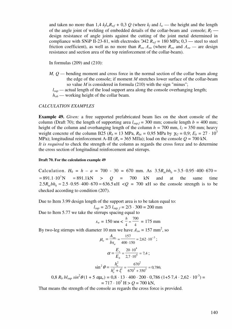
140
and taken no more than 1,4 kflwRwf + 0,3 Q (where kf and lw — the height and the length
of the angle joint of welding of embedded details of the collar-beam and console; Rf design resistance of angle joints against the cutting of the joint metal determined in compliance with SNiP II-23-81, with electrodes Э42 Rwf = 180 MPa; 0,3 — steel to steel friction coefficient), as well as no more than Rsw Аsw (where Rsw and Аsw — are design resistance and section area of the top reinforcement of the collar-beam). In formulas (209) and (210): M, Q — bending moment and cross force in the normal section of the collar beam along
the edge of the console; if moment М stretches lower surface of the collar-beam so value М is considered in formula (210) with the sign "minus";
lsup — actual length of the load support area along the console overhanging length; hob — working height of the collar beam.
CALCULATION EXAMPLES
Example 49. Given: a free supported prefabricated beam lies on the short console of the column (Draft 70); the length of supporting area lsup,f = 300 mm; console length b = 400 mm; height of the column and overhanging length of the column h = 700 mm, l1 = 350 mm; heavy
weight concrete of the column В25 (Rb = 13 MPа, Rbt = 0,95 MPа by γb2 = 0,9; Еb = 27 ⋅ 103 MPа); longitudinal reinforcement А-III (Rs = 365 МПа); load on the console Q = 700 kN. It is required to check the strength of the column as regards the cross force and to determine the cross section of longitudinal reinforcement and stirrups.
Draft 70. For the calculation example 49
Calculation. H0 = h – а = 700 - 30 = 670 mm. As =⋅⋅⋅= 67040095.05.35.3 0bhRbt 3101.891 ⋅= N 1.891= kN > Q = 700 kN and at the same time
5.63667040095.05.25.2 0 =⋅⋅⋅=bhRbt кН <Q = 700 кН so the console strength is to be
checked according to condition (207). Due to Item 3.99 design length of the support area is to be taken equal to:
lsup = 2/3 lsup, f = 2/3 ⋅ 300 = 200 mm Due to Item 5.77 we take the stirrups spacing equal to
sw = 150 мм < h
4
700
4= = 175 mm
By two-leg stirrups with diameter 10 mm we have Аsw = 157 mm2, so
µw
sw
w
A
bs= =
⋅= ⋅
−157
400 1502 62 10
3, ;
α = =⋅
⋅=
E
E
s
b
20 10
2 7 107 4
4
4,
, ;
sin , ;2
2
212
2
2 2
670
670 3500 786θ =
+=
+=
h
h l
o
o
0,8 Rb blsup sin2θ (1 + 5 αµw) = 0,8 ⋅ 13 ⋅ 400 ⋅ 200 · 0,786 (1+5⋅7,4 ⋅ 2,62 ⋅ 10-3) =
= 717 ⋅ 103 H > Q = 700 kN, That means the strength of the console as regards the cross force is provided.

141
Due to condition (208) let’s determine required section area of the console longitudinal reinforcement:
.23
1mm 1002
365670
35010700=
⋅
⋅⋅==
so
sRh
QlA
We take 3 ∅ 22 (As = 1140 mm2). Calculation of embedded elements and connection details
CALCULATION OF EMBEDDED ELEMENTS
- (3.44). Calculation of normal anchors welded to the flat details of steel embedded
elements as regards bending moments, normal and shearing force caused by static load located in one plane of symmetry of the embedded detail (Draft 71), must be made due to the following condition
A
NQ
Ran
an
an
s
=
+
11 2
2
,λδ
, (211)
where Aan — total area of the anchors cross section of the most stressed row;
Nan maximum stretching force in one row of anchors equal to:
NM
z
N
nan
an
= + ; (212)
Qan shearing force on one anchors row equal to:
QQ N
nan
an
an
=− ′0 3,
; (213)
N′an — maximum compression force in one row of anchors determined by formula
′ = −NM
z
N
nan
an
; (214)
In formulas (211) (214): М, N, Q — moment, normal and shearing forces acting on the embedded element; the
moment is determined relating to the axis located in the area of the external surface of the plate and going through the center of gravity of all;
z distance between the end rows of anchors; nan — number of anchors rows along the shearing force direction; if even transfer of
shearing force Q on all anchor rows is not provided, so by determination of shearing force Qan it is necessary to consider no more than four rows;
λ — coefficient determined for anchor rods with diameter 8 – 25 mm for heavy-weight and fine concrete В12,5 – В50 and light-weight concrete В12,5 – В30 by the following formula
λ β=+
4 75
1 015
3
1
,
( , ),
R
A R
b
an s
(215)
but taken no more than 0.7; for heavy-weight and fine concrete of class more
than В50 coefficient λ is taken as for class В50, and for light-weight concrete of class more than В30 — as for class В30. For heavy-weight concrete
coefficient λ can be determined by Table. 28.
In formula (215): Rb, Rs, – in MPа;
By determination of Rb coefficient γb2 (see Item 3.1) is taken equal to 1.0;

142
Aan1 – section area of the anchor rod of the most stressed row наиболее, cm2;
β – coefficient taken equal to: for heavy-weight concrete ................................ 1,0 for fine concrete of group: А ........................................................................ 0,8 Б and В ............................................................... 0,7
For light-weight concrete .................................. ρm/2300
(ρm average concrete density, kg/m3);
δ – coefficient determined by formula
δω
=+
1
1, (216)
but taken no less than 0,15;
here ω = 0,3 N
Q
an
an
by N′an > 0 (with pressure);
ω = 0,6 N
Q by N′an ≤ 0 (no pressure);
if there are no tension forces in anchors so coefficient в δ is taken equal to 1,0. Section area of anchors of other rows must be taken equal to the section area of anchors of the most stressed row. In formulas (212) and (214) normal force N is considered to be positive if it’s directed from the embedded element (see Draft 71), and negative — if it’s directed towards to it.
In case if normal forces Nan and N′an, as well as shearing force Qan during calculation by formulas (212) – (214) get negative value (211), (213) and (216) they are taken equal to
zero. Besides if Nan gets negative value so in formula (213) it’s taken N′an =N.
By location of the embedded element on the top surface of the detail (during concreting)
coefficient λ is decreased by 20 percent and value N′an in formula (213) is taken equal to zero.
Draft 71. Scheme of forces acting on the embedded element
- Calculation of normal anchors of embedded elements as regards bending moments and
shear forces located in two symmetry planes of the embedded elements as well as normal force and torsion moments is made in compliance with "Recommendations for design of steel embedded elements for reinforced concrete structures" (Moscow, Stroyizdat, 1984).
- (3.45). In the embedded element with anchors welded with overlapping at the angle from
15 to 30 degrees (see Item 5.111) inclined anchors located symmetrically relating to the plane of the shearing force is calculated as regards this shearing force (by Q > N, where
N break force) by formula
AQ N
Ran inc
an
s
,
,,=
− ′0 3 (217)
where Aan,inc total area of the cross section of inclined anchors;
Nan see Item 3.101. At the same time it is necessary to install normal anchors calculated by formula (211) by
δ = 1.0 and by values Qan, equal to 0.1 of shearing force determined by formula (213). It is possible to decrease the section area due to transfer of shearing force equal to
incans ARQ ,9.0− on normal anchors. In that case δ is determined by formula (216).
Таблица 28

143
Anchor Coefficient λ for calculation of normal anchors of embedded elements according to class of heavy-weight
concrete and reinforcement
diameter В15 B20 B25 B30 B40 ≥ B50
мм А-I A-II A-III А-I A-II A-III А-I A-II A-III А-I A-II A-III А-I A-II А-III А-I A-II A-III
8 0,60 0,48 0,66 0,53 0,70 0,57 0,70 0,60 0,70 0,66 0,70 0,70
10 0,58 0,52 0,45 0,64 0,57 0,50 0,69 0,62 0,54 0,70 0,65 0,57 0,70 0,70 0,63 0,70 0,70 0,66 12 0,55 0,50 0,43 0,61 0,55 0,48 0,66 0,59 0,52 0,70 0,62 0,55 0,70 0,69 0,60 0,70 0,70 0,63 14 0,53 0,47 0,41 0,58 0,52 0,46 0,63 0,56 0,49 0,66 0,59 0,52 0,70 0,65 0,57 0,70 0,69 0,60 16 0,50 0,45 0,39 0,55 0,49 0,43 0,59 0,53 0,47 0,63 0,56 0,49 0,69 0,62 0,54 0,70 0,65 0,57 18 0,47 0,42 0,37 0,52 0,46 0,41 0,56 0,50 0,44 0,59 0,53 0,46 0,65 0,58 0,51 0,68 0,61 0,54 20 0,44 0,39 0,34 0,49 0,44 0,38 0,52 0,47 0,41 0,55 0,50 0,43 0,61 0,54 0,48 0,64 0,58 0,50 22 0,41 0,37 0,32 0,46 0,41 0,36 0,49 0,44 0,39 0,52 0,46 0,41 0,57 0,51 0,45 0,60 0,54 0,47 25 0,37 0,33 0,29 0,41 0,37 0,32 0,44 0,40 0,35 0,47 0,42 0,37 0,51 0,46 0,40 0,54 0,49 0,43
Notes: 1. For concrete class В 12,5 coefficient λ is to be decreased by 0,02 in comparison with coefficient λ for concrete class В15.
2. Values of coefficient λ are given by γbi = 1,00.
- On welded to the plate supports made of strip steel or reinforcement lugs (see Item 5.114)
it is possible to transfer no more than 30 percent of shearing force acting on the detail by stresses equal to Rb in concrete under supports. At the same time values of shearing force transferred on the anchors of the embedded element is decreased.
- (3.46). The structure of welded embedded elements with welded to them details which
transfer the load on the embedded elements must provide including into work of anchor rods in compliance with the accepted design. External elements of the embedded details and their welded connections are calculated due to SNiP II-23-81. Durinf calculation of plates and corrugated steel as regards break force it is recommended to take that they have hinge connection with normal anchor rods. If the element which transfers the load is welded to the plate along the line of location of one of the anchor rows so during calculation it is recommended to decrease break force by value пaАan1Rs (where na — number of anchors in the present row).
Besides the thickness of plate t of design embedded element must be examined due to the condition
t ≥ 0,25 dR
Ran
s
sq
, (218)
where dan — diameter of the anchor rod required due to the calculation;
Rsq — Design resistance of rolled-steel against the shearing equal to 0.58 Ry (where Ry see SNiP II-23-81). For welded connections types which provide the larger zone of including the plate into work by pulling out of anchor rods out of it (see position 6 of Table 52) the correction of condition (218) is possible for decrease of the plate thickness. If shearing force Q acts on the embedded element with decreased plate thickness total section area (perpendicular to this force) of the section with welded to it elements in the location zone of anchor rods along the force Q is taken no less than the section area of the plate determined by formula (218).
- If the following condition is met
N′an ≤ 0, (219) -

144
-
Related Documents


![Adult Protective Services Toolkit[R.C. 5101.68]; [R.C. 5101.681 - .682] Petition [R.C. 5101.68] • Co. DJFS may petition court for an order authorizing provision of protective services](https://static.cupdf.com/doc/110x72/5e2f6ebd6e54e86940781141/adult-protective-services-toolkit-rc-510168-rc-5101681-682-petition.jpg)