1 Motion Imagery Standards Board Engineering Guideline UAV Datalink Local Metadata Set EG 0601 12 Jan 2006 1 Scope This MISB Engineering Guideline (EG) details the Unmanned Air Vehicle (UAV) Datalink Local Data Set (LDS) for UAV platforms. The UAV Datalink LDS is an extensible SMPTE (Society of Motion Picture Television Engineers) Key-Length-Value (KLV) Local Metadata Set designed for transmission through a wireless communications link (Datalink). This EG provides direction on the creation of a standard Local Data Set for a reliable, bandwidth-efficient exchange of metadata among digital motion imagery systems on UAV platforms. This EG also provides a mapping to Predator Exploitation Support Data (ESD) for continued support of existing metadata systems. The UAV Local Data Set metadata is intended to be produced locally within a UAV platform and included in an MPEG2 Transport Stream (or equivalent transport mechanism). The MPEG2 Transport Stream (or equivalent) also contains compressed motion imagery from sensors such as an Electro-Optical / Infrared (EO/IR) video capture device. Synchronization between the metadata and the appropriate video packet is also required for ensuring the validity of the metadata. The MPEG2 Transport Stream (or equivalent) embedded with UAV LDS metadata is then transmitted over a medium bandwidth (e.g. 1 to 5Mb/s) wireless Datalink and then disseminated. The scope of this document is to provide a framework for an extensible bandwidth efficient Local Data Set which enhances sensor captured imagery with relevant metadata. This EG also provides a mapping between UAV Datalink Local Data Set items, ESD items, and Universal Data Set (UDS) items defined in the latest SMPTE KLV dictionary (RP-210).

Welcome message from author
This document is posted to help you gain knowledge. Please leave a comment to let me know what you think about it! Share it to your friends and learn new things together.
Transcript

1
Motion Imagery Standards Board Engineering Guideline
UAV Datalink Local Metadata Set
EG 0601
12 Jan 2006
1 Scope
This MISB Engineering Guideline (EG) details the Unmanned Air Vehicle (UAV) Datalink
Local Data Set (LDS) for UAV platforms. The UAV Datalink LDS is an extensible SMPTE
(Society of Motion Picture Television Engineers) Key-Length-Value (KLV) Local Metadata Set
designed for transmission through a wireless communications link (Datalink).
This EG provides direction on the creation of a standard Local Data Set for a reliable,
bandwidth-efficient exchange of metadata among digital motion imagery systems on UAV
platforms. This EG also provides a mapping to Predator Exploitation Support Data (ESD) for
continued support of existing metadata systems.
The UAV Local Data Set metadata is intended to be produced locally within a UAV platform
and included in an MPEG2 Transport Stream (or equivalent transport mechanism). The MPEG2
Transport Stream (or equivalent) also contains compressed motion imagery from sensors such as
an Electro-Optical / Infrared (EO/IR) video capture device. Synchronization between the
metadata and the appropriate video packet is also required for ensuring the validity of the
metadata. The MPEG2 Transport Stream (or equivalent) embedded with UAV LDS metadata is
then transmitted over a medium bandwidth (e.g. 1 to 5Mb/s) wireless Datalink and then
disseminated.
The scope of this document is to provide a framework for an extensible bandwidth efficient
Local Data Set which enhances sensor captured imagery with relevant metadata. This EG also
provides a mapping between UAV Datalink Local Data Set items, ESD items, and Universal
Data Set (UDS) items defined in the latest SMPTE KLV dictionary (RP-210).
2
2 References
2.1 SMPTE 336M-2001, Data Encoding Protocol Using Key-Length-Value
2.2 SMPTE RP210.7-2003, Metadata Dictionary Core Video Metadata Profile, Version 1.0,
Video Working Group, 14 March 1997
2.3 MISB RP 0103.1, Timing Reconciliation Metadata Set for Digital Motion Imagery,
11 October 2001
2.4 MISB EG 0104.3, Predator UAV Basic Universal Metadata Set, 15 June 2004
2.5 MISB RP 0107, Bit and Byte Order for Metadata in Motion Imagery Files and Streams,
11 October, 2001
2.6 MIL-STD-2500B V2.1, National Imagery Transmission format Standard, 01 March 2001
2.7 ASI-00209 Rev D, Exploitation Support Data (ESD) External Interface Control Document,
04 December, 2002
2.8 ISO 1000:1992(E), SI units and recommendations for the use of their multiples and of
certain other units, 11 January, 1992
2.9 IEEE 1003.1, Information Technology---Portable Operating System Interface (POSIX),
2004

3
3 Introduction
A SMPTE 336M Universal Data Set (UDS) provides access to a range of KLV formatted
metadata items. Transmitting the 16-byte key, basic encoding rules (BER) formatted length, and
data value is appropriate for applications where bandwidth isn’t a concern. However,
transmitting the 16-byte universal key quickly uses up the available bandwidth in bandwidth-
challenged environments.
The Motion Imagery Standards Board (MISB) Engineering Guideline MISB EG 0104.3 entitled
“Predator UAV Basic Universal Metadata Set” shows a translation between basic ESD and
Universal Data Set (UDS) metadata items that exist in the most current version of the SMPTE
KLV dictionary. The UDS items in the MISB EG 0104.3 document are more appropriate for
higher bandwidth interfaces (e.g. > 10Mb/s) like for dissemination, whereas this document
targets low to medium bandwidth interfaces (e.g. 1 to 5Mb/s).
UAV platforms typically use a wireless communications channel that allots a limited amount of
bandwidth for metadata. Because of the bandwidth disadvantages of using a Universal Data Set,
it is more desirable to use a Local Data Set for transmission over a UAV Datalink. As discussed
in SMPTE 336M, a Local Data Set can use a 1, 2 or 4-byte key with a 1, 2, 4-byte, or BER
encoded length. This UAV Local Data Set uses a 1-byte key and BER encoded length to
minimize bandwidth requirements while still allowing the LDS ample room for growth (up to
255 metadata items).
This EG identifies a way to encode metadata locally in the airborne platform into a standard
KLV Local Data Set. This standardized method is intended to be extensible to include future
relevant metadata with mappings between new LDS, UDS, and ESD metadata items (where
appropriate). When a new metadata LDS item is added or required, action must be taken to add
an equivalent (i.e. identical in data format) Universal Data Set metadata item to the proper
metadata dictionary (public or private) if the UDS metadata item does not already exist.
This method also provides a mapping between Local Data Set items and currently implemented
Universal Data Set items defined in the SMPTE KLV dictionary (RP-210).
3.1 Local Data Set Changes and Updates
This document defines the UAV Datalink Local Metadata Set and is under configuration
management. Any changes to this document must be accompanied by a document revision and
date change and coordinated with the managing organization.
Software applications that implement this interface should allow for metadata items in the UAV
Local Data Set that are unknown so that they are forward compatible with future versions of the
interface.
NOTE: Universal Keys which correspond exactly in data content to the Local Data Set metadata
items defined here have not been secured at initial release. These “UDS Mirror” metadata keys
are represented with “TBD” in the LDS metadata table in section 5.

4
4 UAV Datalink Local Data Set This section defines the UAV Datalink Local Data Set (LDS). The keys that are supported in
this LDS are defined and mapped to metadata items in the SMPTE KLV Dictionary (RP-210) as
well as the Exploitation Support Data (ESD) specification where appropriate. The UAV
Datalink Local Metadata Set is SMPTE 336M KLV compliant.
The following section defines the metadata items contained in the LDS.
The subsections that follow discuss the topics listed below:
- 4.1: LDS Packet Structure
- 4.2: Data Collection and Dissemination
- 4.3: Timestamping
- 4.4: Error Detection
The 16-byte Universal Key for this UAV Local Data Set is to be defined by the MISB. A key
history is provided below as a way to track the keys used in engineering and development.
Key: 06 0E 2B 34 - 01 01 01 01 - 0F 00 00 00 - 00 00 00 00
Date Released: November 2005
Description: Experimental node key used in software development efforts at General Atomics
prior to the assignment of a defined key.
Key: 06 0E 2B 34 - 02 03 01 01 - 01 79 01 01 - 01 xx xx xx
Date Released: October 25, 2005
Description: This key was released as a placeholder within this document. Much development
has been based around draft versions of this document which has used this key in some software
implementations.

5
4.1 LDS Packet Structure
Key 8: Platform True Airspeed L = 1 0x00
Key 10: Platform Designation L = 10 “Predator B”
Universal KeyFor a
UAV Local Data Set
LengthOf Value
field
ValueUAV Metadata in Local Data Set Format
Key 2: Unix Time Stamp - Microseconds L = 8 0x00 11 22 33 44 55 66 77
Key 39: Outside Air Temperature L = 1 0x00
Key 38: Density Altitude L = 2 0x00 11
Key 24: Frame Center Longitude L = 4 0x00 11 22 33
Key 23: Frame Center Latitude L = 4 0x00 11 22 33
Key 1: Checksum L = 4 0x00 11 22 33
A timestamp
is mandatory
Arranging metadata elements in order is not
required.
All metadata elements need not be included in each Local Data Set packet.
A Checksum is optional
but recommended.
K: Local Keys are
1 byte Long
L: BER
Encoded Length
V: Variable
Length Payload
L: BER
Encoded Length
V: Variable
Length Data
K: 16-bytes
UAV LDS Packet Example
Figure 4-1: Example of a UAV Local Data Set Packet
Figure 4-1 shows the general format of how the LDS is configured. It is required that each LDS
packet contain a Unix-based timestamp that represents the time of birth of the metadata within
the LDS packet. Time stamping of metadata is discussed in section 4.2. A checksum metadata
item is also strongly recommended to be included in each LDS packet. Checksums are discussed
in section 4.3.
Any combination of metadata items can be included in a UAV Local Data Set packet. Also, to
be SMPTE 336M compliant, the items within the UAV LDS can be arranged in any order.
However, in practice the timestamp is often positioned at the beginning of an LDS packet.
Similarly, the checksum often appears as the last metadata item due to algorithms surrounding its
computation and creation.
4.1.1 Bit and Byte ordering
All metadata is represented using big-endian (Most Significant Byte (MSB) first) encoding.
Bytes are big-endian bit encoding (most significant bit (msb) first).

6
4.1.2 Length Field Encoding
The length field is encoded using basic encoding rules (BER) for either short or long form
encoding of octets. This length encoding method provides the greatest level of flexibility for
variable length data contained within a KLV packet.
In practice, the majority of metadata items in a LDS packet will use the short form of length
encoding which requires only a single byte to represent the length. The length of the entire LDS
packet, however, is often represented using the long form of length encoding since the majority
of packets have a payload larger than 127 bytes. The length of a single packet is represented by
2 bytes whenever the payload portion of the LDS packet is less than 256 bytes. Both short and
long form encoding is discussed in the subsections that follow.
See SMPTE 336M section 3.2 for further details.
4.1.2.1 BER Short Form Length Encoding
For UAV LDS packets and data elements shorter than 128 bytes, the length field is encoded
using the BER short form. Length fields using the short form are represented using a single byte
(8 bits). The most significant bit in this byte signals that the long form is being used. The last
seven bits depict the number of bytes that follow the BER encoded length. An example LDS
packet using a short form encoded length is shown below:
Figure 4-2: Example Short Form Length Encoding
4.1.2.2 BER Long form length encoding
For LDS packets and data elements longer than 127 bytes, the length field is encoded using the
BER long form. The long form encodes length fields using multiple bytes. The first byte
indicates long form encoding as well as the number of subsequent bytes that represent the length.
The bytes that follow the leading byte are the encoding of an unsigned binary integer which is
equal to the number of bytes in the payload portion of the packet. An example LDS packet using
a long form encoded length is shown below:
Figure 4-3: Example Long Form Length Encoding

7
4.2 Data Collection and Dissemination
Within the air vehicle, metadata is collected, processed, and then distributed by the flight
computer (or equivalent) through the most appropriate interface (RS-422, 1553, Ethernet,
Firewire, etc.). See the figure below:
Figure 4-4: System Architecture
Sensors and other metadata sources pass metadata to the flight computer.
The flight computer (or equivalent) places a timestamp in the UAV LDS packet prior to passing
it to the Video Encoder / Packet Multiplexer. See section 4.3 for more information about using
timestamps in the LDS metadata packet.
The flight computer merges all appropriate metadata items and a timestamp into a LDS packet
and transmits it with a checksum to the video encoder Packet Multiplexer. The encoder adds the
metadata to a transport stream mechanism which is passed through a communications link to a
remote client process that can decode and process the video and metadata contained within the
transport stream. The remote client process can then display and/or distribute the video and
metadata as appropriate.

8
4.3 Time Stamping
Every LDS KLV packet is required to include a Unix-based timestamp as a way to correspond
the metadata with a standardized time reference. Unix-time is useful to associate metadata with
frames, and for reviewing time-critical events at a later date. This section describes how to
include a timestamp within a UAV Local Data Set packet.
Metadata sources and the flight computer (or equivalent) are coordinated to operate on the same
coordinated time which is GPS derived. A source of metadata, or the flight computer, provides a
timestamp for inclusion in a LDS packet. The timestamp assists the accuracy of synchronizing
each frame to its corresponding metadata set.
The mandatory timestamp is named “Unix Timestamp”. The timestamp (key 2) is an 8 byte
unsigned integer that represents the number of microseconds that have elapsed since midnight
(00:00:00), January 1, 1970. This date is known as the Unix epoch and is discussed in the IEEE
POSIX standard IEEE 1003.1.
4.3.1 Packet Timestamp
An LDS Packet Timestamp is inserted at the beginning of the value portion of a UAV LDS
packet. One LDS metadata item is required to represent Unix Time and is recommended to be
inserted just after the BER encoded length field of the LDS packet, although this positioning is
not manditory.
The timestamp represented by Key 2 (Unix Timestamp) applies to all metadata in the LDS
packet. This timestamp corresponds to the time of birth of all the data within the LDS packet.
This time can be used to associate the metadata with a particular video frame and be displayed or
monitored appropriately.
An example LDS packet containing a timestamp is show below:
Figure 4-5: Packet Timestamp Example

9
4.4 Error Detection
To help prevent erroneous metadata from being presented with video, it is highly recommended
that a 16-bit checksum is included in every UAV Local Data Set packet. The checksum can be
located anywhere within the packet and is recommended to be placed at the end due to the
processes that compute the checksum. The checksum is a running 16-byte sum through the
entire LDS packet starting with the 16 byte Local Data Set key and ending with summing the
length field of the checksum data item. The figure below shows the data range that the
checksum is performed over:
Figure 4-6: Checksum Computation Range
An example algorithm for calculating the checksum is shown below:
unsigned short bcc_16 ( unsigned char * buff, // Pointer to the first byte in the 16-byte UAV LDS key. unsigned short len ) // Length from 16-byte UDS key up to 1-byte checksum length. { // Initialize Checksum and counter variables. unsigned short bcc = 0, i; // Sum each 16-bit chunk within the buffer into a checksum for ( i = 0 ; i < len; i++) bcc += buff[i] << (8 * ((i + 1) % 2)); return bcc; } // end of bcc_16 ()
If the calculated checksum of the received LDS packet does not match the checksum stored in
the packet, the user must discard this packet as being invalid. The lost LDS packet is of little
concern since another packet is available within reasonable proximity (in both data and time) to
this lost packet.

10
5 UAV Local Data Set Tables
This section defines the content of the UAV Local Data Set as well as translation between LDS & ESD, and LDS and PUDS data types.
5.1 UAV Local Data Set Items
Each UAV Local Data Set item is assigned an integer value for its key, a descriptive name, and also has fields indicating the units, range, format, and
length of the data item. More detailed information about the data item is included in the Notes column.
Notes:
- The columns labeled “Units”, “Range”, “Format”, “LEN” (for length) and “Notes” all apply to the Local Data Set ONLY and not ESD or
UDS data types.
- An “x” within a field below indicates that no data is available..
- The “UDS Mirror” column is the Universal Data Set metadata key reserved to represent the length and data format specified by the
corresponding LDS metadata item. The key is the only parameter which differs between UDS and LDS item.
- The “UDS Name” column is an existing metadata key which the UAV LDS is mapped to in some applications.
KEY LDS Name UDS Mirror ESD ESD Name UDS UDS Name Units Format Len Notes
1 Checksum TBD x x x x None uint16 2 Checksum used to detect errors within a UAV Local Data Set packet. Lower 16-bits of summation. Performed on entire LDS packet, including 16-byte UDS key and 1-byte checksum length.
2 UNIX Time Stamp TBD x x 06 0E 2B 34 01 01 01 04 07 02 01 01 01 05 00 00
User Defined Time Stamp - microseconds since 1970
Microseconds
uint64 8 Microseconds elapsed since midnight (00:00:00), January 1, 1970. Derived from the POSIX IEEE 1003.1 standard. Resolution: 1 microsecond.
3 Mission ID TBD Mn Mission Number 06 0E 2B 34 01 01 01 01 01 05 05 00 00 00 00 00
Episode Number String ISO7 V Descriptive Mission Identifier to distinguish event or sortie. Format of String TBD. Maximum 127 characters.
4 Platform Tail Number
TBD x x x x String ISO7 V Identifier of platform as posted. e.g.: "AF008", "BP101", etc. Maximum 127 characters.

11
KEY LDS Name UDS Mirror ESD ESD Name UDS UDS Name Units Format Len Notes
5 Platform Heading Angle
TBD Ih UAV Heading (INS)
06 0E 2B 34 01 01 01 07 07 01 10 01 06 00 00 00
Platform Heading Angle
Degrees uint16 2 Aircraft heading angle. Relative between fuselage chord line and True North. Map 0..(2^16-1) to 0..360. Resolution: ~5.5 milli degrees.
6 Platform Pitch Angle
TBD Ip UAV Pitch (INS) 06 0E 2B 34 01 01 01 07 07 01 10 01 05 00 00 00
Platform Pitch Angle
Degrees int16 2 Aircraft pitch angle. Relative between fuselage chord line and the horizon. Positive angles above horizon, negative below. Map -(2^15-1)..(2^15-1) to +/-20. Use -(2^15) as "out of range" indicator. -(2^15) = 0x8000. Resolution: ~610 micro degrees.
7 Platform Roll Angle
TBD Ir UAV Roll (INS) 06 0E 2B 34 01 01 01 07 07 01 10 01 04 00 00 00
Platform Roll Angle
Degrees int16 2 Aircraft roll angle. Relative between horizon and wing chord line. Wings level is 0 degrees. Positive angles for elevated left wing. Map (-2^15-1)..(2^15-1) to +/-50. Use -(2^15) as "out of range" indicator. -(2^15) = 0x8000. Res: ~1525 micro deg.
8 Platform True Airspeed
TBD As True Airspeed x x Meters / Second
uint8 1 True airspeed (TAS) of platform. Idicated Airspeed adjusted for temperature and altitude. 0..255 meters/sec. 1 m/s = 1.94384449 knots. Resolution: 1 meter/second.
9 Platform Indicated Airspeed
TBD Ai Indicated Airspeed
x x Meters / Second
uint8 1 Indicated airspeed (IAS) of platform. Derived from Pitot tube and static pressure sensors. 0..255 meters/sec. 1 m/s = 1.94384449 knots. Resolution: 1 meter/second.

12
KEY LDS Name UDS Mirror ESD ESD Name UDS UDS Name Units Format Len Notes
10 Platform Designation
TBD Pc Project ID Code 06 0E 2B 34 01 01 01 01 01 01 20 01 00 00 00 00
Device Designation
String ISO7 V Use "Project Id Code" from EG0104.3. e.g.: 'Predator', 'Predator B', 'Outrider', 'Pioneer', 'IgnatER', 'Warrior', etc. Maximum 127 characters.
11 Image Source Sensor
TBD Sn Sensor Name 06 0E 2B 34 01 01 01 01 04 20 01 02 01 01 00 00
Image Source Device
String ISO7 V String of image source sensor. e.g.: 'EO Nose', 'EO Zoom (DLTV)', 'EO Spotter', 'IR Mitsubishi PtSi Model 500', 'IR Mitsubishi PtSi Model 600', 'IR InSb Amber Model TBT', 'LYNX SAR Imagery', 'TESAR Imagery', etc. Maximum 127 characters.
12 Image Coordinate System
TBD Ic Image Coordinate System
06 0E 2B 34 01 01 01 01 07 01 01 01 00 00 00 00
Image Coordinate System
String ISO7 V String of the image coordinate system used. e.g.: 'Geodetic WGS84', 'Geocentric WGS84', 'UTM', 'None', etc. Maximum 127 characters.
13 Sensor Latitude TBD Sa Sensor Latitude 06 0E 2B 34 01 01 01 03 07 01 02 01 02 04 02 00
Device Latitude Degrees int32 4 Sensor Latitude. Based on WGS84 ellipsoid. Map -(2^31-1)..(2^31-1) to +/-90. Use -(2^31) as an "error" indicator. -(2^31) = 0x80000000. Resolution: ~42 nano degrees.
14 Sensor Longitude
TBD So Sensor Longitude
06 0E 2B 34 01 01 01 03 07 01 02 01 02 06 02 00
Device Longitude
Degrees int32 4 Sensor Longitude. Based on WGS84 ellipsoid. Map -(2^31-1)..(2^31-1) to +/-180. Use -(2^31) as an "error" indicator. -(2^31) = 0x80000000. Resolution: ~84 nano degrees.
15 Sensor True Altitude
TBD Sl Sensor Altitude 06 0E 2B 34 01 01 01 01 07 01 02 01 02 02 00 00
Device Altitude Meters uint16 2 Altitude of sensor as measured from Mean Sea Level (MSL). Map 0..(2^16-1) to -900..19000 meters. 1 meter = 3.2808399 feet. Resolution: ~0.3 meters.

13
KEY LDS Name UDS Mirror ESD ESD Name UDS UDS Name Units Format Len Notes
16 Sensor Horizontal Field of View
TBD Fv Field of View 06 0E 2B 34 01 01 01 02 04 20 02 01 01 08 00 00
Field of View (FOV-Horizontal)
Degrees uint16 2 Horizontal field of view of selected imaging sensor. Map 0..(2^16-1) to 0..180. Resolution: ~2.7 milli degrees.
17 Sensor Vertical Field of View
TBD x x x x Degrees uint16 2 Vertical field of view of selected imaging sensor. Map 0..(2^16-1) to 0..180. Resolution: ~2.7 milli degrees.
18 Sensor Relative Azimuth Angle
TBD x x x x Degrees uint32 4 Relative rotation angle of sensor to aircraft platform in azimuth. Rotation angle between aircraft fuselage chord and camera pointing direction as seen from above the platform. Map 0..(2^32-1) to 0..360. Resolution: ~84 nano degrees.
19 Sensor Relative Depression Angle
TBD x x x x Degrees int32 4 Relative Depression Angle of sensor to aircraft platform. Level flight with camera pointing forward is zero degrees. Negative angles down. Map -(2^31-1)..(2^31-1) to +/-180. Use -(2^31) as an "error" indicator. -(2^31) = 0x80000000. Res: ~84 ndeg.
20 Sensor Relative Roll Angle
TBD x x x x Degrees uint32 4 Relative roll angle of sensor to aircraft platform. Twisting angle of camera about lens axis. Top of image is zero degrees. Positive angles are clockwise when looking from behind camera. Map 0..(2^32-1) to 0..360. Resolution: ~84 nano degrees.
21 Slant Range TBD Sr Slant Range 06 0E 2B 34 01 01 01 01 07 01 08 01 01 00 00 00
Slant Range Meters uint32 4 Slant range in meters. Distance to target. Map 0..(2^32-1) to 0..5000000 meters. 1 nautical mile (knot) = 1852 meters. Resoluiton: ~1.2 milli meters.

14
KEY LDS Name UDS Mirror ESD ESD Name UDS UDS Name Units Format Len Notes
22 Target Width TBD Tw Target Width 06 0E 2B 34 01 01 01 01 07 01 09 02 01 00 00 00
Target Width Meters uint16 2 Target Width within sensor field of view. Map 0..(2^16-1) to 0..10000 meters. 1 meter = 3.2808399 feet. Resolution: ~.16 meters.
23 Frame Center Latitude
TBD Ta Target Latitude 06 0E 2B 34 01 01 01 01 07 01 02 01 03 02 00 00
Frame Center Latitude
Degrees int32 4 Terrain Latitude of frame center. Based on WGS84 ellipsoid. Map -(2^31-1)..(2^31-1) to +/-90. Use -(2^31) as an "error" indicator. -(2^31) = 0x80000000. Resolution: ~42 nano degrees.
24 Frame Center Longitude
TBD To Target Longitude
06 0E 2B 34 01 01 01 01 07 01 02 01 03 04 00 00
Frame Center Longitude
Degrees int32 4 Terrain Longitude of frame center. Based on WGS84 ellipsoid. Map -(2^31-1)..(2^31-1) to +/-180. Use -(2^31) as an "error" indicator. -(2^31) = 0x80000000. Resolution: ~84 nano degrees.
25 Frame Center Elevation
TBD x x 06 0E 2B 34 01 01 01 06 07 01 02 03 10 00 00 00
Frame Center Elevation
Meters uint16 2 Terrain elevation at frame center. Map 0..(2^16-1) to -900..19000 meters. Resolution: ~0.3 meters.
26 Corner Latitude Point 1
TBD Rg SAR Latitude 4 06 0E 2B 34 01 01 01 03 07 01 02 01 03 07 01 00
Corner Latitude Point 1 (Decimal Degrees)
Degrees int16 4 Frame Latitude, upper left corner. Based on WGS84 ellipsoid. Map -(2^15-1)..(2^15-1) to +/-90. Use -(2^15) as an "error" indicator. -(2^15) = 0x8000. Resolution: ~2.7 milli degrees.

15
KEY LDS Name UDS Mirror ESD ESD Name UDS UDS Name Units Format Len Notes
27 Corner Longitude Point 1
TBD Rh SAR Longitude 4 06 0E 2B 34 01 01 01 03 07 01 02 01 03 0B 01 00
Corner Longitude Point 1 (Decimal Degrees)
Degrees int16 4 Frame Longitude, upper left corner. Based on WGS84 ellipsoid. Map -(2^15-1)..(2^15-1) to +/-180. Use -(2^15) as an "error" indicator. -(2^15) = 0x8000. Resolution: ~5.5 milli degrees.
28 Corner Latitude Point 2
TBD Ra SAR Latitude 1 06 0E 2B 34 01 01 01 03 07 01 02 01 03 08 01 00
Corner Latitude Point 2 (Decimal Degrees)
Degrees int16 4 Frame Latitude, upper right corner. Based on WGS84 ellipsoid. Map -(2^15-1)..(2^15-1) to +/-90. Use -(2^15) as an "error" indicator. -(2^15) = 0x8000. Resolution: ~2.7 milli degrees.
29 Corner Longitude Point 2
TBD Rb SAR Longitude 1 06 0E 2B 34 01 01 01 03 07 01 02 01 03 0C 01 00
Corner Longitude Point 2 (Decimal Degrees)
Degrees int16 4 Frame Longitude, upper right corner. Based on WGS84 ellipsoid. Map -(2^15-1)..(2^15-1) to +/-180. Use -(2^15) as an "error" indicator. -(2^15) = 0x8000. Resolution: ~5.5 milli degrees.
30 Corner Latitude Point 3
TBD Rc SAR Latitude 2 06 0E 2B 34 01 01 01 03 07 01 02 01 03 09 01 00
Corner Latitude Point 3 (Decimal Degrees)
Degrees int16 4 Frame Latitude, lower right corner. Based on WGS84 ellipsoid. Map -(2^15-1)..(2^15-1) to +/-90. Use -(2^15) as an "error" indicator. -(2^15) = 0x8000. Resolution: ~2.7 milli degrees.
31 Corner Longitude Point 3
TBD Rd SAR Longitude 2 06 0E 2B 34 01 01 01 03 07 01 02 01 03 0D 01 00
Corner Longitude Point 3 (Decimal Degrees)
Degrees int16 4 Frame Longitude, lower right corner. Based on WGS84 ellipsoid. Map -(2^15-1)..(2^15-1) to +/-180. Use -(2^15) as an "error" indicator. -(2^15) = 0x8000. Resolution: ~5.5 milli degrees.

16
KEY LDS Name UDS Mirror ESD ESD Name UDS UDS Name Units Format Len Notes
32 Corner Latitude Point 4
TBD Re SAR Latitude 3 06 0E 2B 34 01 01 01 03 07 01 02 01 03 0A 01 00
Corner Latitude Point 4 (Decimal Degrees)
Degrees int16 4 Frame Latitude, lower left corner. Based on WGS84 ellipsoid. Map -(2^15-1)..(2^15-1) to +/-90. Use -(2^15) as an "error" indicator. -(2^15) = 0x8000. Resolution: ~2.7 milli degrees.
33 Corner Longitude Point 4
TBD Rf SAR Longitude 3 06 0E 2B 34 01 01 01 03 07 01 02 01 03 0E 01 00
Corner Longitude Point 4 (Decimal Degrees)
Degrees int16 4 Frame Longitude, lower left corner. Based on WGS84 ellipsoid. Map -(2^15-1)..(2^15-1) to +/-180. Use -(2^151) as an "error" indicator. -(2^15) = 0x8000. Resolution: ~5.5 milli degrees.
34 Icing Detected TBD Id Icing Detected Register x Icing Code
uint8 1 Flag for icing detected at aircraft location. 0: Detector off 1: No icing Detected 2: Icing Detected
35 Wind Direction TBD Wd Wind Direction x x Degrees uint16 2 Wind direction at aircraft location. Map 0..(2^16-1) to 0..360. Resolution: ~5.5 milli degrees.
36 Wind Speed TBD Ws Wind Speed x x Meters / Second
uint8 1 Wind speed at aircraft location. Map 0..255 to 0..100 meters/second. 1 m/s = 1.94384449 knots. Resolution: ~0.4 meters / second.
37 Static Pressure TBD Ps Static Pressure x x Millibar uint16 2 Static pressure at aircraft location. Map 0..(2^16-1) to 0..5000 mbar. 1 mbar = 0.0145037738 PSI. Resolution: ~0.08 Millibar
17
KEY LDS Name UDS Mirror ESD ESD Name UDS UDS Name Units Format Len Notes
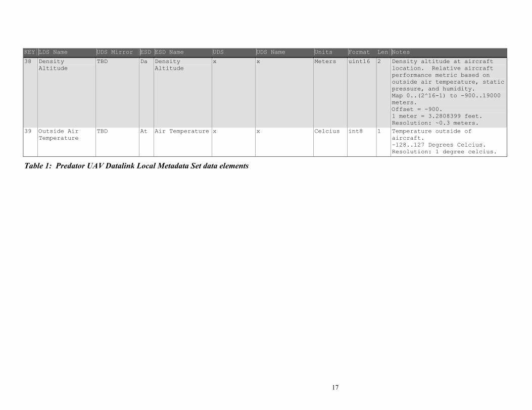
38 Density Altitude
TBD Da Density Altitude
x x Meters uint16 2 Density altitude at aircraft location. Relative aircraft performance metric based on outside air temperature, static pressure, and humidity. Map 0..(2^16-1) to -900..19000 meters. Offset = -900. 1 meter = 3.2808399 feet. Resolution: ~0.3 meters.
39 Outside Air Temperature
TBD At Air Temperature x x Celcius int8 1 Temperature outside of aircraft. -128..127 Degrees Celcius. Resolution: 1 degree celcius.
Table 1: Predator UAV Datalink Local Metadata Set data elements

18
5.2 Sensor Image Geoposition Corner Metadata
The Sensor Image Corner Latitude/Longitude metadata consists of the items shown in Figure 10.
Corner coordinates are numbered to conform to National Imagery Transmission Format (NITF)
Standard numbering convention for single image frame corner coordinates:
Figure 4-7 shows a detailed mapping between metadata items for each corner point.
ESD
ESD
ESD
ESD
LDS
ESD
UDS
ESD
ESD
ESD
LDS
LDS
LDS
LDS
LDS
LDS
LDS
UDS
UDS
UDS
UDS
UDS
UDS
UDS
Figure 5-1: Corner Point Mapping
See the NITF Standards document MIL-STD-2500B Version 2.1 for more information about
corner coordinates. Corners not corresponding to geographic locations, i.e., above the horizon,
are not to be included. This numbering scheme is different than the one used in the ESD
interface described in ASI-00209 Rev D “Exploitation Support Data (ESD) External Interface
Control Document”.
Each LDS Corner Point item assigned here maps to one UDS Corner Point entry in the SMPTE
RP210 dictionary. The LDS corner points use a 4-byte signed integer mapped between +/-90 for
Latitude entries, and +/-180 for Longitude entries whereas each Latitude and Longitude UDS
corner point has one 8-byte floating point value that corresponds to decimal degrees.

19
6 Conversions and Mappings Between Metadata Types
Metadata items that are common amongst PLDS, UDS, and ESD data formats each convey
identical information. However, since each metadata format represents the same metadata items
differently (e.g. mapped integer, float, string, etc.), the data resolution between format types is
different. This section provides conversions and mappings between PLDS, UDS, and ESD
metadata items.
6.1 Key 1: Checksum Conversion
LDS 1 LDS Name Checksum
UDS Mirror of LDS Item Units Range Format TBD None 0..(2^16-1) uint16
Notes
- Checksum used to detect errors within a UAV Local Data Set packet.
- Lower 16-bits of summation.
- Performed on entire LDS packet, including 16-byte UDS key and 1-byte checksum length.
x
UDS x ESD x
UDS Name x ESD Name x
Units Range Format Units Range Format x x x x x x
Notes Notes
- x - x
UDS Conversion ESD Cnversion x
To UDS:
- x
To LDS:
- x
x
To ESD:
- x
To LDS:
- x
6.1.1 Example 16-bit Checksum Code unsigned short bcc_16 ( unsigned char * buff, // Pointer to the first byte in the 16-byte PLDS key. unsigned short len ) // Length from 16-byte UDS key up to 1-byte checksum length. { unsigned short bcc = 0, i; // Initialize Checksum and counter variables. for ( i = 0 ; i < len; i++) bcc += buff[i] << (8 * ((i + 1) % 2)); return bcc; } // end of bcc_16 ()
6.1.2 Sample Checksum Data 64 bits to checksum: 060E 2B34 0200 81BB
060E + 2B34 3142 + 0200 3442 + 81BB B4FD <-- Final Checksum

20
6.2 Key 2: UNIX Time Stamp Conversion
LDS 2 LDS Name UNIX Time Stamp
UDS Mirror of LDS Item Units Range Format TBD Microseconds 0..(2^64-1) uint64
Notes
- Microseconds elapsed since midnight (00:00:00), January 1, 1970.
- Derived from the POSIX IEEE 1003.1 standard.
- Resolution: 1 microsecond.
UDS 06 0E 2B 34 01 01 01 04 07 02 01 01 01 05 00 00
ESD x
UDS Name User Defined Time Stamp - microseconds since 1970
ESD Name x
Units Range Format Units Range Format uSec uint64 uint64 x x x
Notes Notes
- Time Stamp application defined by user.
- 64 bit integer which represents the number of microseconds since Jan 1, 1970 UTC derived from the POSIX (IEEE 1003.1) standard.
- x
UDS Conversion ESD Cnversion x
To UDS:
- UDS = LDS
To LDS:
- LDS = UDS
x
To ESD:
- x
To LDS:
- x
6.2.1 UNIX Time Stamp
Unix time, or POSIX time, is a system use to discretely label a scale of time. This system is
widely used within systems of differing underlying architectures. Unix time is an encoding of
Coordinated Universal Time (UTC) and therefore accounts for the addition (or subtraction) of
leap seconds. Leap seconds are used to synchronize the UTC clock metric with the yearly
rotation period of the earth about the sun.

21
6.3 Key 3: Mission ID Conversion
LDS 3 LDS Name Mission ID
UDS Mirror of LDS Item Units Range Format TBD String 1..127 ISO7
Notes
- Descriptive Mission Identifier to distinguish event or sortie.
- Format of String TBD.
- Maximum 127 characters.
x
UDS 06 0E 2B 34 01 01 01 01 01 05 05 00 00 00 00 00
ESD Mn
UDS Name Episode Number ESD Name Mission Number
Units Range Format Units Range Format Number x Float Number x x
Notes Notes
- x - Number to distinguish different missions started on a given day.
UDS Conversion ESD Cnversion x
To UDS:
- TBD
To LDS:
- TBD
x
To ESD:
- TBD
To LDS:
- TBD
6.3.1 Example Mission ID
TBD

22
6.4 Key 4: Platform Tail Number Conversion
LDS 4 LDS Name Platform Tail Number
UDS Mirror of LDS Item Units Range Format TBD String 1..127 ISO7
Notes
- Identifier of platform as posted.
- e.g.: "AF008", "BP101", etc.
- Maximum 127 characters.
x
UDS x ESD x
UDS Name x ESD Name x
Units Range Format Units Range Format x x x x x x
Notes Notes
- x - x
UDS Conversion ESD Cnversion x
To UDS:
- x
To LDS:
- x
x
To ESD:
- x
To LDS:
- x
6.4.1 Example Platform Tail Number
TBD
23
6.5 Key 5: Platform Heading Angle Conversion
LDS 5 LDS Name Platform Heading Angle
UDS Mirror of LDS Item Units Range Format TBD Degrees 0..360 uint16
Notes
- Aircraft heading angle. Relative between fuselage chord line and True North.
- Map 0..(2^16-1) to 0..360.
- Resolution: ~5.5 milli degrees.
LDS_dec = ( )LDS_rangeuint_range * LDS_uint
UDS 06 0E 2B 34 01 01 01 07 07 01 10 01 06 00 00 00
ESD Ih
UDS Name Platform Heading Angle ESD Name UAV Heading (INS)
Units Range Format Units Range Format Degrees 0..360 Float Degrees 0..359.99 DDD.HH
Notes Notes
- Heading angle of platform expressed in degrees.
- The Heading of an airborne platform is the angle from True North of its longitudinal axis projected onto the horizontal plane.
- True heading of the aircraft.
UDS Conversion ESD Cnversion
UDS_dec = ( )36065535 * LDS_uint
To UDS:
- UDS = (float)(360/0xFFFF * LDS)
To LDS:
- LDS = (uint16)round((0xFFFF/360 * UDS))
ESD_dec = ( )36065535 * LDS_uint
To ESD:
- Convert LDS to decimal.
- Convert decimal to ASCII.
To LDS:
- Convert ASCII to decimal.
- Map decimal to uint16.
6.5.1 Example Platform Heading Angle
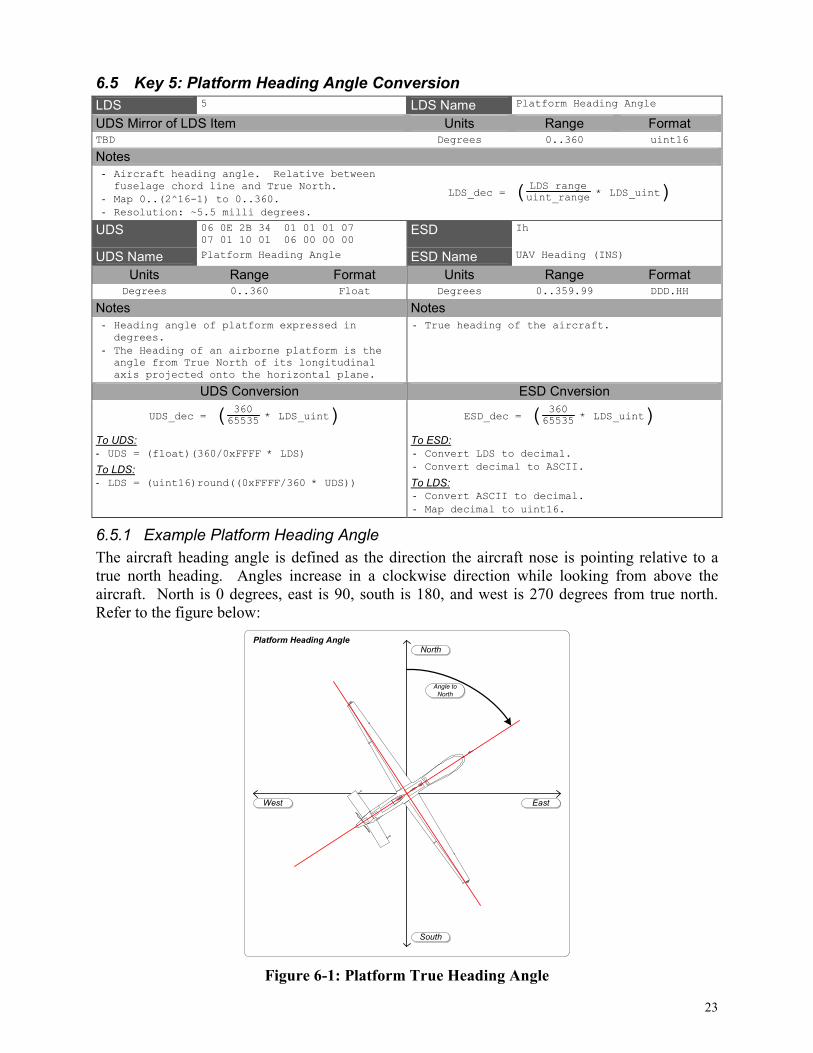
The aircraft heading angle is defined as the direction the aircraft nose is pointing relative to a
true north heading. Angles increase in a clockwise direction while looking from above the
aircraft. North is 0 degrees, east is 90, south is 180, and west is 270 degrees from true north.
Refer to the figure below:
South
North
EastWest
Angle to
North
Platform Heading Angle
Figure 6-1: Platform True Heading Angle

24
6.6 Key 6: Platform Pitch Angle Conversion
LDS 6 LDS Name Platform Pitch Angle
UDS Mirror of LDS Item Units Range Format TBD Degrees +/- 20 int16
Notes
- Aircraft pitch angle. Relative between fuselage chord line and the horizon.
- Positive angles above horizon, negative below.
- Map -(2^15-1)..(2^15-1) to +/-20.
- Use -(2^15) as "out of range" indicator.
- -(2^15) = 0x8000.
- Resolution: ~610 micro degrees.
LDS_dec = ( )LDS_rangeint_range * LDS_int
UDS 06 0E 2B 34 01 01 01 07 07 01 10 01 05 00 00 00
ESD Ip
UDS Name Platform Pitch Angle ESD Name UAV Pitch (INS)
Units Range Format Units Range Format Degrees +/- 90 Float Degrees +/- 20.0 PDD.HH
Notes Notes
- Pitch angle of platform expressed in degrees.
- The Pitch of an airborne platform describes the angle of its longitudinal (front-to-back) axis makes with the horizontal (i.e., equi-potential gravitational surface);
- Pitch angle of the aircraft.
UDS Conversion ESD Cnversion
UDS_dec = ( )4065534 * LDS_int
To UDS:
- UDS = (float)(40/0xFFFE * LDS)
To LDS:
- LDS = (int32)round((0xFFFE/40 * UDS))
ESD_dec = ( )4065534 * LDS_int
To ESD:
- Convert LDS to decimal.
- Convert decimal to ASCII.
To LDS:
- Convert ASCII to decimal.
- Map decimal to int16.
6.6.1 Example Platform Pitch Angle
The pitch angle of the aircraft in flight is the angle the fuselage chord makes with the plane of
level flight. This plane is parallel to the horizon. Positive angles represent flight operations
where the nose of the aircraft is above the horizon line.
Pitch angles are limited to +/- 20 degrees to increase metadata resolution within this range.
Should the aircraft experience flight maneuvers beyond this range, an “out of range” indication
shall be made within this metadata item. Refer to the figure below:
Figure 6-2: Platform Pitch Angle

25
6.7 Key 7: Platform Roll Angle Conversion
LDS 7 LDS Name Platform Roll Angle
UDS Mirror of LDS Item Units Range Format TBD Degrees +/- 50 int16
Notes
- Aircraft roll angle. Relative between horizon and wing chord line. Wings level is 0 degrees. Positive angles for elevated left wing.
- Map (-2^15-1)..(2^15-1) to +/-50.
- Use -(2^15) as "out of range" indicator.
- -(2^15) = 0x8000.
- Res: ~1525 micro deg.
LDS_dec = ( )LDS_rangeint_range * LDS_int
UDS 06 0E 2B 34 01 01 01 07 07 01 10 01 04 00 00 00
ESD Ir
UDS Name Platform Roll Angle ESD Name UAV Roll (INS)
Units Range Format Units Range Format Degrees +/- 90 Float Degrees +/- 50.0 PDD.HH
Notes Notes
- Roll angle of platform expressed in degrees.
- The Roll of an airborne platform is rotation about its longitudinal (front-to-back) axis;
- Wings level is zero degrees, positive (negative) angles describe a platform orientation with the right wing down(up).
- Roll angle of the aircraft.
UDS Conversion ESD Cnversion
UDS_dec = ( )10065534 * LDS_int
To UDS:
- UDS = (float)(100/0xFFFE * LDS)
To LDS:
- LDS = (int32)round((0xFFFE/100 * UDS))
ESD_dec = ( )10065534 * LDS_int
To ESD:
- Convert LDS to decimal.
- Convert decimal to ASCII.
To LDS:
- Convert ASCII to decimal.
- Map decimal to int16.
6.7.1 Example Platform Roll Angle
The roll angle of the aircraft is defined as the angle the wing chord makes relative to the
horizontal plane. Positive angles correspond to the left wing being raised above the horizon
plane.
Roll angles are limited to +/- 50 degrees to increase metadata resolution within this range.
Should the aircraft experience flight maneuvers beyond this range, an “out of range” indication
shall be made within this metadata item. Refer to the figure below:
Figure 6-3: Platform Roll Angle

26
6.8 Key 8: Platform True Airspeed Conversion
LDS 8 LDS Name Platform True Airspeed
UDS Mirror of LDS Item Units Range Format TBD Meters / Second 0..255 uint8
Notes
- True airspeed (TAS) of platform. Idicated Airspeed adjusted for temperature and altitude.
- 0..255 meters/sec.
- 1 m/s = 1.94384449 knots.
- Resolution: 1 meter/second.
LDS_dec = LDS_int
UDS x ESD As
UDS Name x ESD Name True Airspeed
Units Range Format Units Range Format x x x Knots 0..999 N
Notes Notes
- x - True airspeed of the aircraft.
UDS Conversion ESD Cnversion x
To UDS:
- x
To LDS:
- x
ESD_dec = ( )LDS_uint * 1.94384449 knots 1 meters/second
To ESD:
- Map LDS to integer.
- Convert integer value to ASCII.
To LDS:
- Convert ASCII to integer.
- Map integer to uint8.
6.8.1 Example Platform True Airspeed
True airspeed is the actual speed an aircraft is traveling relative through the air mass in which it
flies. Without a relative wind condition, the true airspeed is equal to the speed over the ground.
The true airspeed of the aircraft is calculated using the outside temperature, impact pressure
(pitot tube), and static pressure.

27
6.9 Key 9: Platform Indicated Airspeed Conversion
LDS 9 LDS Name Platform Indicated Airspeed
UDS Mirror of LDS Item Units Range Format TBD Meters / Second 0..255 uint8
Notes
- Indicated airspeed (IAS) of platform. Derived from Pitot tube and static pressure sensors.
- 0..255 meters/sec.
- 1 m/s = 1.94384449 knots.
- Resolution: 1 meter/second.
LDS_dec = LDS_int
UDS x ESD Ai
UDS Name x ESD Name Indicated Airspeed
Units Range Format Units Range Format x x x Knots 0..999 N
Notes Notes
- x - Indicated airspeed of the aircraft.
UDS Conversion ESD Cnversion x
To UDS:
- x
To LDS:
- x
ESD_dec = ( )LDS_uint * 1.94384449 knots 1 meters/second
To ESD:
- Map LDS to integer.
- Convert integer value to ASCII.
To LDS:
- Convert ASCII to integer.
- Map integer to uint8.
6.9.1 Example Platform Indicated Airspeed
The indicated airspeed of an aircraft is calculated from the difference between static pressure,
and impact pressure. Static pressure is measured by a sensor not directly in the air stream and
impact pressure is measured by a Pitot tube positioned strategically within the air stream. The
difference in pressure while moving provides a way to calculate the indicated platform airspeed.

28
6.10 Key 10: Platform Designation Conversion
LDS 10 LDS Name Platform Designation
UDS Mirror of LDS Item Units Range Format TBD String 0..127 ISO7
Notes
- Use "Project Id Code" from EG0104.3.
- e.g.: 'Predator', 'Predator B', 'Outrider', 'Pioneer', 'IgnatER', 'Warrior', etc.
- Maximum 127 characters.
x
UDS 06 0E 2B 34 01 01 01 01 01 01 20 01 00 00 00 00
ESD Pc
UDS Name Device Designation ESD Name Project ID Code
Units Range Format Units Range Format String 1..32 ISO7 Number 0..99 N
Notes Notes
- Identifies the "house name" of the device used in capturing or generating the essence.
- 32 characters maximum.
- ISO7 character set.
- The Project ID of the Collection Platform (e.g., Predator, Outrider, Pioneer, etc.)
UDS Conversion ESD Cnversion x
To UDS:
- No conversion necessary.
To LDS:
- No conversion necessary.
x
To ESD:
- Convert string to ID code.
To LDS:
- Convert ID code to string.
6.10.1 Example Platform Designation
The platform designation metadata item distinguishes which platform is carrying the motion
imagery generating payload equipment. Some current platforms are shown below:
Figure 6-4: Example Platforms

29
6.11 Key 11: Image Source Sensor Conversion
LDS 11 LDS Name Image Source Sensor
UDS Mirror of LDS Item Units Range Format TBD String 1..127 ISO7
Notes
- String of image source sensor.
- e.g.: 'EO Nose', 'EO Zoom (DLTV)', 'EO Spotter', 'IR Mitsubishi PtSi Model 500', 'IR Mitsubishi PtSi Model 600', 'IR InSb Amber Model TBT', 'LYNX SAR Imagery', 'TESAR Imagery', etc.
- Maximum 127 characters.
x
UDS 06 0E 2B 34 01 01 01 01 04 20 01 02 01 01 00 00
ESD Sn
UDS Name Image Source Device ESD Name Sensor Name
Units Range Format Units Range Format String 1..32 ISO7 Name Code 0..7 N
Notes Notes
- Indicates the type of the image source.
- 32 characters maximum.
- ISO7 character set.
- Identifies the source of the video image.
- 0: EO Nose
- 1: EO Zoom (DLTV)
- 2: EO Spotter
- 3: IR Mitsubishi PtSi Model 500
- 4: IR Mitsubishi PtSi Model 600
- 5: IR InSb Amber Model TBD
- 6: Lynx SAR Imagery
- 7: TESAR Imagery
UDS Conversion ESD Cnversion x
To UDS:
- No conversion necessary.
To LDS:
- No conversion necessary.
x
To ESD:
- Convert string to ID code.
To LDS:
- Convert ID code to string.
6.11.1 Example Image Source Sensor
A sample imaging source sensor is shown in the figure below:
Figure 6-5: Sample Imaging Sensor

30
6.12 Key 12: Image Coordinate System Conversion
LDS 12 LDS Name Image Coordinate System
UDS Mirror of LDS Item Units Range Format TBD String 1..127 ISO7
Notes
- String of the image coordinate system used.
- e.g.: 'Geodetic WGS84', 'Geocentric WGS84', 'UTM', 'None', etc.
- Maximum 127 characters.
x
UDS 06 0E 2B 34 01 01 01 01 07 01 01 01 00 00 00 00
ESD Ic
UDS Name Image Coordinate System ESD Name Image Coordinate System
Units Range Format Units Range Format String 1..4 ISO7 Code 0..3 N
Notes Notes
- Identifies the Digital Geographic Information Exchange Standard (DIGEST) geo-referenced coordinate system used at image capture.
- **** 4 characters maximum. ****
- ISO7 character set.
- Identifies the image coordinate system used.
- 0: Geodetic WGS84
- 1: Geocentric WGS 84
- 2: UTM
- 3: None
UDS Conversion ESD Cnversion x
To UDS:
- No conversion necessary.
To LDS:
- No conversion necessary.
x
To ESD:
- Convert string to ID code.
To LDS:
- Convert ID code to string.
6.12.1 World Geodetic System – 1984 (WGS 84)
The World Geodetic System of 1984 (WGS 84) is a 3-D, Earth-centered reference system
developed originally by the U.S. Defense Mapping Agency. This system is the official GPS
reference system.
6.12.2 Universal Transverse Mercator (UTM)
UTM is the projection of the earth onto a cylinder. The Mercator projection is a conformal
projection, meaning that angles and small shapes on the globe project as the same angles on the
map. This causes the scale between the center and outer-most portions of the conformal
projection to vary greatly.
Applications exist which convert between UTM and WGS84 coordinate systems and their
different datum references.

31
6.13 Key 13: Sensor Latitude Conversion
LDS 13 LDS Name Sensor Latitude
UDS Mirror of LDS Item Units Range Format TBD Degrees +/- 90 int32
Notes
- Sensor Latitude. Based on WGS84 ellipsoid.
- Map -(2^31-1)..(2^31-1) to +/-90.
- Use -(2^31) as an "error" indicator.
- -(2^31) = 0x80000000.
- Resolution: ~42 nano degrees.
LDS_dec = ( )LDS_rangeint_range * LDS_int
UDS 06 0E 2B 34 01 01 01 03 07 01 02 01 02 04 02 00
ESD Sa
UDS Name Device Latitude ESD Name Sensor Latitude
Units Range Format Units Range Format Degrees +/- 90 Double Degrees +/- 90.0 PDDMMSST
Notes Notes
- Specifies a sensor's geographic location in decimal degrees of latitude.
- Positive values indicate northern hemisphere.
- Negative values indicate southern hemisphere.
- Latitude of the aircraft. + Means North Latitude. All Latitude coordinates use WGS84.
UDS Conversion ESD Cnversion
UDS_dec = ( )1804294967294 * LDS_int
To UDS:
- UDS = (double)(180/0xFFFFFFFE * LDS)
To LDS:
- LDS = (int32)round((0xFFFFFFFE/180 * UDS))
ESD_dec = ( )1804294967294 * LDS_int
To ESD:
- Convert LDS to decimal.
- Convert decimal to ASCII.
To LDS:
- Convert ASCII to decimal.
- Map decimal to int32.
6.13.1 Sensor Latitude
Latitude is the angular distance north or south of the earth's equator, measured in degrees along a
meridian. Generated from GPS/INS information and based on the WGS84 coordinate system.

32
6.14 Key 14: Sensor Longitude Conversion
LDS 14 LDS Name Sensor Longitude
UDS Mirror of LDS Item Units Range Format TBD Degrees +/- 180 int32
Notes
- Sensor Longitude. Based on WGS84 ellipsoid.
- Map -(2^31-1)..(2^31-1) to +/-180.
- Use -(2^31) as an "error" indicator.
- -(2^31) = 0x80000000.
- Resolution: ~84 nano degrees.
LDS_dec = ( )LDS_rangeint_range * LDS_int
UDS 06 0E 2B 34 01 01 01 03 07 01 02 01 02 06 02 00
ESD So
UDS Name Device Longitude ESD Name Sensor Longitude
Units Range Format Units Range Format Degrees +/- 180 Double Degrees +/- 180.00 PDDDMMSST
Notes Notes
- Specifies a sensor's geographic location in decimal degrees of longitude.
- Positive values indicate eastern hemisphere.
- Negative values indicate western hemisphere.
- Longitude of the aircraft. + Means East Longitude. All Longitude coordinates use WGS84.
UDS Conversion ESD Cnversion
UDS_dec = ( )3604294967294 * LDS_int
To UDS:
- UDS = (double)(360/0xFFFFFFFE * LDS)
To LDS:
- LDS = (int32)round(0xFFFFFFFE/360 * UDS)
ESD_dec = ( )3604294967294 * LDS_int
To ESD:
- Convert LDS to decimal.
- Convert decimal to ASCII.
To LDS:
- Convert ASCII to decimal.
- Map decimal to int32.
6.14.1 Example Sensor Longitude
Longitude is the angular distance on the earth's surface, measured east or west from the prime
meridian at Greenwich, England, to the meridian passing through a position of interest.
Generated from GPS/INS information and based on the WGS84 coordinate system.

33
6.15 Key 15: Sensor True Altitude Conversion
LDS 15 LDS Name Sensor True Altitude
UDS Mirror of LDS Item Units Range Format TBD Meters -900..19000 uint16
Notes
- Altitude of sensor as measured from Mean Sea Level (MSL).
- Map 0..(2^16-1) to -900..19000 meters.
- 1 meter = 3.2808399 feet.
- Resolution: ~0.3 meters.
LDS_dec = ( )LDS_rangeuint_range * LDS_int - Offset
UDS 06 0E 2B 34 01 01 01 01 07 01 02 01 02 02 00 00
ESD Sl
UDS Name Device Altitude ESD Name Sensor Altitude
Units Range Format Units Range Format Meters Float Float Feet +/- 0..99,999 PN
Notes Notes
- Altitude of sensor as measured from Mean Sea Level (MSL), (default metres).
- Altitude of the aircraft (MSL).
UDS Conversion ESD Cnversion
UDS_dec = ( )1990065535 * LDS_uint - 900
To UDS:
- UDS = (float)((19900/0xFFFF) * LDS - 900)
To LDS:
- LDS = (uint16)round(0xFFFF/19900 * (UDS + 900))
ESD_dec = ( )1990065535*LDS_uint-900 *
3.2808399 ft1 m
To ESD:
- Convert LDS to decimal.
- Account for units.
- Convert decimal to ASCII.
To LDS:
- Convert ESD ASCII to decimal.
- Account for units.
- Map decimal to uint16.
6.15.1 Sensor True Altitude
True Altitude is the true vertical distance above mean sea level. Measurement is GPS derived.

34
6.16 Key 16: Sensor Horizontal Field of View Conversion
LDS 16 LDS Name Sensor Horizontal Field of View
UDS Mirror of LDS Item Units Range Format TBD Degrees 0..180 uint16
Notes
- Horizontal field of view of selected imaging sensor.
- Map 0..(2^16-1) to 0..180.
- Resolution: ~2.7 milli degrees.
LDS_dec = ( )LDS_rangeuint_range * LDS_uint
UDS 06 0E 2B 34 01 01 01 02 04 20 02 01 01 08 00 00
ESD Fv
UDS Name Field of View (FOV-Horizontal) ESD Name Field of View
Units Range Format Units Range Format Degrees 0..180 Float Degrees 0..180.00 DDD.HH
Notes Notes
- Sensor Horizontal field of view. - Angle of view of the lens on the selected camera. Horizontal, across baseline of image, projected onto the terrain (flat terrain model at DTED or other best available elevation data).
UDS Conversion ESD Cnversion
UDS_dec = ( )18065535 * LDS_uint
To UDS:
- UDS = (float)(180/0xFFFF * LDS)
To LDS:
- LDS = (uint16)round((0xFFFF/180 * UDS))
ESD_dec = ( )18065535 * LDS_uint
To ESD:
- Convert LDS to decimal.
- Convert decimal to ASCII.
To LDS:
- Convert ESD ASCII to decimal.
- Map decimal to uint16.
6.16.1 Sensor Horizontal Field of View
The field of view of a lens is defined as the angle over the focal plane where objects are recorded
on a film or electro-optical sensor. Field of view is dependent upon the focal length of the lens,
and the physical size of the sensor. Typical imaging devices have a square or rectangular
imaging sensor. The image (or sequence of images) is typically captured as a square or rectangle
and displayed to a user with image edges perpendicular to level sight.
The distance between left edge and right edge is represented as an angle in the horizontal field of
view metadata item. Refer to the figure below:
Nadir
Zenith
Horizon
Right Wing Left Wing
Horizontal Field of View
Earth
Horizontal
Field of View
Image Center
Figure 6-6: Horizontal Field of View

35
6.17 Key 17: Sensor Vertical Field of View Conversion
LDS 17 LDS Name Sensor Vertical Field of View
UDS Mirror of LDS Item Units Range Format TBD Degrees 0..180 uint16
Notes
- Vertical field of view of selected imaging sensor.
- Map 0..(2^16-1) to 0..180.
- Resolution: ~2.7 milli degrees.
LDS_dec = ( )LDS_rangeuint_range * LDS_uint
UDS x ESD x
UDS Name x ESD Name x
Units Range Format Units Range Format x x x x x x
Notes Notes
- x - x
UDS Conversion ESD Cnversion x
To UDS:
- x
To LDS:
- x
x
To ESD:
- x
To LDS:
- x
6.17.1 Sensor Vertical Field of View
The field of view of a lens is defined as the angle over the focal plane where objects are recorded
on a film or electro-optical sensor. Field of view is dependent upon the focal length of the lens,
and the physical size of the sensor. Typical imaging devices have a square or rectangular
imaging sensor. The image (or sequence of images) is typically captured as a square or rectangle
and displayed to a user with image edges perpendicular to level sight.
The distance between top edge and bottom edge is represented as an angle in the vertical field of
view metadata item. Refer to the figure below:
Figure 6-7: Vertical Field of View

36
6.18 Key 18: Sensor Relative Azimuth Angle Conversion
LDS 18 LDS Name Sensor Relative Azimuth Angle
UDS Mirror of LDS Item Units Range Format TBD Degrees 0..360 uint32
Notes
- Relative rotation angle of sensor to aircraft platform in azimuth. Rotation angle between aircraft fuselage chord and camera pointing direction as seen from above the platform.
- Map 0..(2^32-1) to 0..360.
- Resolution: ~84 nano degrees.
LDS_dec = ( )LDS_rangeuint_range * LDS_uint
UDS x ESD x
UDS Name x ESD Name x
Units Range Format Units Range Format x x x x x x
Notes Notes
- x - x
UDS Conversion ESD Cnversion x
To UDS:
- x
To LDS:
- x
x
To ESD:
- x
To LDS:
- x
6.18.1 Example Sensor Relative Azimuth Angle
The relative rotation angle of the sensor is the angle formed between the line made by the
fuselage and the sensor pointing direction in azimuth. Refer to the figure below:
South
North
EastWest
Angle to
North
Sensor Relative Rotation Angle
Image Center
Aircraft
heading
Sensor Relative
Rotation Angle
Figure 6-8: Relative Rotation Angle
37
6.19 Key 19: Sensor Relative Depression Angle Conversion
LDS 19 LDS Name Sensor Relative Depression Angle
UDS Mirror of LDS Item Units Range Format TBD Degrees +/- 180 int32
Notes
- Relative Depression Angle of sensor to aircraft platform. Level flight with camera pointing forward is zero degrees. Negative angles down.
- Map -(2^31-1)..(2^31-1) to +/-180.
- Use -(2^31) as an "error" indicator.
- -(2^31) = 0x80000000.
- Res: ~84 ndeg.
LDS_dec = ( )LDS_rangeint_range * LDS_int
UDS x ESD x
UDS Name x ESD Name x
Units Range Format Units Range Format x x x x x x
Notes Notes
- x - x
UDS Conversion ESD Cnversion x
To UDS:
- x
To LDS:
- x
x
To ESD:
- x
To LDS:
- x
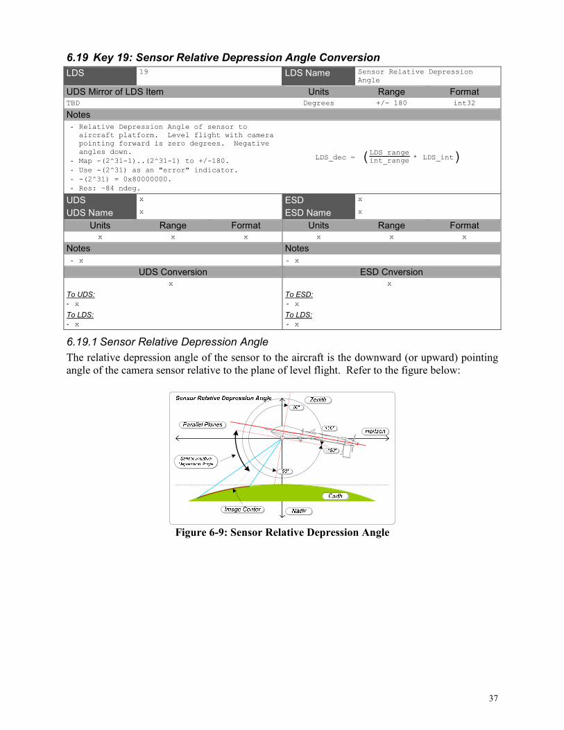
6.19.1 Sensor Relative Depression Angle
The relative depression angle of the sensor to the aircraft is the downward (or upward) pointing
angle of the camera sensor relative to the plane of level flight. Refer to the figure below:
Figure 6-9: Sensor Relative Depression Angle
38
6.20 Key 20: Sensor Relative Roll Angle Conversion
LDS 20 LDS Name Sensor Relative Roll Angle
UDS Mirror of LDS Item Units Range Format TBD Degrees 0..360 uint32
Notes
- Relative roll angle of sensor to aircraft platform. Twisting angle of camera about lens axis. Top of image is zero degrees. Positive angles are clockwise when looking from behind camera.
- Map 0..(2^32-1) to 0..360.
- Resolution: ~84 nano degrees.
LDS_dec = ( )LDS_rangeuint_range * LDS_uint
UDS x ESD x
UDS Name x ESD Name x
Units Range Format Units Range Format x x x x x x
Notes Notes
- x - x
UDS Conversion ESD Cnversion x
To UDS:
- x
To LDS:
- x
x
To ESD:
- x
To LDS:
- x
6.20.1 Example Sensor Relative Roll Angle
Sensors that are able to rotate their camera about the lens axis make use of this sensor relative
roll angle. A roll angle of zero degrees occurs when the top and bottom edges of the captured
image lie perpendicular to the plane created by the sensor relative depression angle axis.
Positive angles are clockwise when looking from behind the camera.

39
6.21 Key 21: Slant Range Conversion
LDS 21 LDS Name Slant Range
UDS Mirror of LDS Item Units Range Format TBD Meters 0..5,000,000 uint32
Notes
- Slant range in meters. Distance to target.
- Map 0..(2^32-1) to 0..5000000 meters.
- 1 nautical mile (knot) = 1852 meters.
- Resoluiton: ~1.2 milli meters.
LDS_dec = ( )LDS_rangeuint_range * LDS_uint
UDS 06 0E 2B 34 01 01 01 01 07 01 08 01 01 00 00 00
ESD Sr
UDS Name Slant Range ESD Name Slant Range
Units Range Format Units Range Format Meters Float Float Knot 0..18.00 II.HH
Notes Notes
- Distance from the sensor to the center point on ground of the framed subject (image) depicted in the captured essence, (default metres)
- Distance between the sensor and the target
UDS Conversion ESD Cnversion
UDS_dec = ( )50000004294967295 * LDS_uint
To UDS:
- UDS = (float)(5000000/0xFFFFFFFF * LDS)
To LDS:
- LDS = (uint32)round(0xFFFFFFFF/5000000 * UDS)
ESD_dec = ( )50000004294967295 * LDS_int *
1852 knot1 m
To ESD:
- Convert LDS to decimal.
- Account for units.
- Convert knots to ASCII.
To LDS:
- Convert ESD ASCII to decimal.
- Account for units.
- Convert feet to uint32.
6.21.1 Example Sensor Slant Range
The slant range is the distance between the sensor and image center. Refer to the figure below.
Figure 6-10: Sensor Slant Range

40
6.22 Key 22: Target Width Conversion
LDS 22 LDS Name Target Width
UDS Mirror of LDS Item Units Range Format TBD Meters 0..10000 uint16
Notes
- Target Width within sensor field of view.
- Map 0..(2^16-1) to 0..10000 meters.
- 1 meter = 3.2808399 feet.
- Resolution: ~.16 meters.
LDS_dec = LDS_uint
UDS 06 0E 2B 34 01 01 01 01 07 01 09 02 01 00 00 00
ESD Tw
UDS Name Target Width ESD Name Target Width
Units Range Format Units Range Format Meters Float Float Feet 0..99,999 N
Notes Notes
- Horizontal half width of the target frame image; used to compute the four corner points of the frame, (default metres)
- Width of the EO/IR Payloads field of view on the ground
UDS Conversion ESD Cnversion
UDS_dec = ( )1000065535 * LDS_uint
To UDS:
- UDS = (float)(10000/0xFFFF * LDS)
To LDS:
- LDS = (uint32)round(0xFFFF/10000 * UDS)
ESD_dec = ( )1000065535 * LDS_int *
3.2808399 ft1 m
To ESD:
- Convert LDS to decimal.
- Account for units.
- Convert feet to ASCII.
To LDS:
- Convert ESD ASCII to decimal.
- Account for units.
- Convert meters to uint32.
6.22.1 Example Sensor Target Width
The target width is the linear ground distance between the center of both sides of the captured
image. Refer to figure below.
Nadir
Zenith
Horizon
Right Wing Left Wing
Target Width
Earth
Image Center
Target Width
Figure 6-11: Target Width

41
6.23 Key 23: Frame Center Latitude Conversion
LDS 23 LDS Name Frame Center Latitude
UDS Mirror of LDS Item Units Range Format TBD Degrees +/- 90 int32
Notes
- Terrain Latitude of frame center. Based on WGS84 ellipsoid.
- Map -(2^31-1)..(2^31-1) to +/-90.
- Use -(2^31) as an "error" indicator.
- -(2^31) = 0x80000000.
- Resolution: ~42 nano degrees.
LDS_dec = ( )LDS_rangeint_range * LDS_int
UDS 06 0E 2B 34 01 01 01 01 07 01 02 01 03 02 00 00
ESD Ta
UDS Name Frame Center Latitude ESD Name Target Latitude
Units Range Format Units Range Format Degrees +/- 90 Double Degrees +/- 90.0 PDDMMSST
Notes Notes
- Specifies the video frame center point geographic location in decimal degrees of latitude.
- Positive values indicate northern hemisphere.
- Negative values indicate southern hemisphere.
- Latitude of the EO/IR payload's aimpoint on the ground. + Means North lattitude. All latitude coordinates use WGS84.
UDS Conversion ESD Cnversion
UDS_dec = ( )1804294967294 * LDS_int
To UDS:
- UDS = (double)(180/0xFFFFFFFE * LDS)
To LDS:
- LDS = (int32)round(0xFFFFFFFE/180 * UDS)
ESD_dec = ( )1804294967294 * LDS_int
To ESD:
- Convert LDS to decimal.
- Convert decimal to ASCII.
To LDS:
- Convert ASCII to decimal.
- Map decimal to int32.
6.23.1 Frame Center Latitude
The center of the captured image or image sequence has a real earth coordinate represented by a
latitude-longitude-altitude triplet. Frame centers that lie above the horizon do not correspond to
a point on the earth and should either not be reported, or be reported as an “error”.

42
6.24 Key 24: Frame Center Longitude Conversion
LDS 24 LDS Name Frame Center Longitude
UDS Mirror of LDS Item Units Range Format TBD Degrees +/- 180 int32
Notes
- Terrain Longitude of frame center. Based on WGS84 ellipsoid.
- Map -(2^31-1)..(2^31-1) to +/-180.
- Use -(2^31) as an "error" indicator.
- -(2^31) = 0x80000000.
- Resolution: ~84 nano degrees.
LDS_dec = ( )LDS_rangeint_range * LDS_int
UDS 06 0E 2B 34 01 01 01 01 07 01 02 01 03 04 00 00
ESD To
UDS Name Frame Center Longitude ESD Name Target Longitude
Units Range Format Units Range Format Degrees +/- 180 Double Degrees +/- 180.00 PDDDMMSST
Notes Notes
- Specifies the video frame center point geographic location in decimal degrees of longitude.
- Positive values indicate eastern hemisphere.
- Negative values indicate western hemisphere.
- Longitude of the EO/IR payload's aimpoint on the ground. + Means East longitude. All longitude coordinates use WGS84.
UDS Conversion ESD Cnversion
UDS_dec = ( )1804294967294 * LDS_int
To UDS:
- UDS = (double)(180/0xFFFFFFFE * LDS)
To LDS:
- LDS = (int32)round(0xFFFFFFFE/180 * UDS)
ESD_dec = ( )1804294967294 * LDS_int
To ESD:
- Convert LDS to decimal.
- Convert decimal to ASCII.
To LDS:
- Convert ASCII to decimal.
- Map decimal to int32.
6.24.1 Example Sensor Frame Center Longitude
The center of the captured image or image sequence has a real earth coordinate represented by a
latitude-longitude-altitude triplet. Frame centers that lie above the horizon do not correspond to
a point on the earth and should either not be reported, or be reported as an “error”.

43
6.25 Key 25: Frame Center Elevation Conversion
LDS 25 LDS Name Frame Center Elevation
UDS Mirror of LDS Item Units Range Format TBD Meters -900..19000 uint16
Notes
- Terrain elevation at frame center.
- Map 0..(2^16-1) to -900..19000 meters.
- Resolution: ~0.3 meters.
LDS_dec = ( )LDS_uint - Offset
UDS 06 0E 2B 34 01 01 01 06 07 01 02 03 10 00 00 00
ESD x
UDS Name Frame Center Elevation ESD Name x
Units Range Format Units Range Format x x x x x x
Notes Notes
- Check latest released dictionary. - x
UDS Conversion ESD Cnversion x
To UDS:
- x
To LDS:
- x
x
To ESD:
- x
To LDS:
- x
6.25.1 Example Frame Center Elevation
The center of the captured image or image sequence has a real earth coordinate represented by a
latitude-longitude-altitude triplet. Frame centers that lie above the horizon do not correspond to
a point on the earth and should either not be reported, or be reported as an “error”.

44
6.26 Key 26: Corner Latitude Point 1 Conversion
LDS 26 LDS Name Corner Latitude Point 1
UDS Mirror of LDS Item Units Range Format TBD Degrees +/- 90 int16
Notes
- Frame Latitude, upper left corner. Based on WGS84 ellipsoid.
- Map -(2^15-1)..(2^15-1) to +/-90.
- Use -(2^15) as an "error" indicator.
- -(2^15) = 0x8000.
- Resolution: ~2.7 milli degrees.
LDS_dec = ( )LDS_rangeint_range * LDS_int
UDS 06 0E 2B 34 01 01 01 03 07 01 02 01 03 07 01 00
ESD Rg
UDS Name Corner Latitude Point 1 (Decimal Degrees)
ESD Name SAR Latitude 4
Units Range Format Units Range Format Degrees +/- 90 Double Degrees +/- 90.0 PDDMMSST
Notes Notes
- Latitude coordinate of corner 1 of an image or bounding rectangle.
- Positive (+) is northern hemisphere.
- Negative (-) is southern hemisphere.
- The latitude of the upper left corner of the SAR image box.
UDS Conversion ESD Cnversion
UDS_dec = ( )18065534 * LDS_int
To UDS:
- UDS = (double)(180/0xFFFE * LDS)
To LDS:
- LDS = (int32)round(0xFFFE/180 * UDS)
ESD_dec = ( )18065534 * LDS_int
To ESD:
- Convert LDS to decimal.
- Convert decimal to ASCII.
To LDS:
- Convert ASCII to decimal.
- Map decimal to int16.
6.26.1 Corner Latitude Point 1
The corner points of the captured image or image sequence have a real earth coordinate
represented by a latitude-longitude pair. Corner points that lie above the horizon do not
correspond to a point on the earth and should either not be reported, or be reported as an “error”.
Corner point 1 is the upper left corner of the captured image.

45
6.27 Key 27: Corner Longitude Point 1 Conversion
LDS 27 LDS Name Corner Longitude Point 1
UDS Mirror of LDS Item Units Range Format TBD Degrees +/- 180 int16
Notes
- Frame Longitude, upper left corner. Based on WGS84 ellipsoid.
- Map -(2^15-1)..(2^15-1) to +/-180.
- Use -(2^15) as an "error" indicator.
- -(2^15) = 0x8000.
- Resolution: ~5.5 milli degrees.
LDS_dec = ( )LDS_rangeint_range * LDS_int
UDS 06 0E 2B 34 01 01 01 03 07 01 02 01 03 0B 01 00
ESD Rh
UDS Name Corner Longitude Point 1 (Decimal Degrees)
ESD Name SAR Longitude 4
Units Range Format Units Range Format Degrees +/- 180 Double Degrees +/- 180.0 PDDDMMSST
Notes Notes
- Longitude coordinate of corner 1 of an image or bounding rectangle.
- Positive (+) is eastern hemisphere.
- Negative (-) is western hemisphere.
- The longitude of the upper left corner of the SAR image box.
UDS Conversion ESD Cnversion
UDS_dec = ( )36065534 * LDS_int
To UDS:
- UDS = (double)(360/0xFFFE * LDS)
To LDS:
- LDS = (int32)round(0xFFFE/360 * UDS)
ESD_dec = ( )36065534 * LDS_int
To ESD:
- Convert LDS to decimal.
- Convert decimal to ASCII.
To LDS:
- Convert ASCII to decimal.
- Map decimal to int16.
6.27.1 Corner Longitude Point 1
The corner points of the captured image or image sequence have a real earth coordinate
represented by a latitude-longitude pair. Corner points that lie above the horizon do not
correspond to a point on the earth and should either not be reported, or be reported as an “error”.
Corner point 1 is the upper left corner of the captured image.

46
6.28 Key 28: Corner Latitude Point 2 Conversion
LDS 28 LDS Name Corner Latitude Point 2
UDS Mirror of LDS Item Units Range Format TBD Degrees +/- 90 int16
Notes
- Frame Latitude, upper right corner. Based on WGS84 ellipsoid.
- Map -(2^15-1)..(2^15-1) to +/-90.
- Use -(2^15) as an "error" indicator.
- -(2^15) = 0x8000.
- Resolution: ~2.7 milli degrees.
LDS_dec = ( )LDS_rangeint_range * LDS_int
UDS 06 0E 2B 34 01 01 01 03 07 01 02 01 03 08 01 00
ESD Ra
UDS Name Corner Latitude Point 2 (Decimal Degrees)
ESD Name SAR Latitude 1
Units Range Format Units Range Format Degrees +/- 90 Double Degrees +/- 90.0 PDDMMSST
Notes Notes
- Latitude coordinate of corner 2 of an image or bounding rectangle.
- Positive (+) is northern hemisphere.
- Negative (-) is southern hemisphere.
- The latitude of the upper right corner of the SAR image box.
UDS Conversion ESD Cnversion
UDS_dec = ( )18065534 * LDS_int
To UDS:
- UDS = (double)(180/0xFFFE * LDS)
To LDS:
- LDS = (int32)round(0xFFFE/180 * UDS)
ESD_dec = ( )18065534 * LDS_int
To ESD:
- Convert LDS to decimal.
- Convert decimal to ASCII.
To LDS:
- Convert ASCII to decimal.
- Map decimal to int16.
6.28.1 Corner Latitude Point 2
The corner points of the captured image or image sequence have a real earth coordinate
represented by a latitude-longitude pair. Corner points that lie above the horizon do not
correspond to a point on the earth and should either not be reported, or be reported as an “error”.
Corner point 2 is the upper right corner of the captured image.

47
6.29 Key 29: Corner Longitude Point 2 Conversion
LDS 29 LDS Name Corner Longitude Point 2
UDS Mirror of LDS Item Units Range Format TBD Degrees +/- 180 int16
Notes
- Frame Longitude, upper right corner. Based on WGS84 ellipsoid.
- Map -(2^15-1)..(2^15-1) to +/-180.
- Use -(2^15) as an "error" indicator.
- -(2^15) = 0x8000.
- Resolution: ~5.5 milli degrees.
LDS_dec = ( )LDS_rangeint_range * LDS_int
UDS 06 0E 2B 34 01 01 01 03 07 01 02 01 03 0C 01 00
ESD Rb
UDS Name Corner Longitude Point 2 (Decimal Degrees)
ESD Name SAR Longitude 1
Units Range Format Units Range Format Degrees +/- 180 Double Degrees +/- 180.0 PDDDMMSST
Notes Notes
- Longitude coordinate of corner 2 of an image or bounding rectangle.
- Positive (+) is eastern hemisphere.
- Negative (-) is western hemisphere.
- The longitude of the upper right corner of the SAR image box.
UDS Conversion ESD Cnversion
UDS_dec = ( )36065534 * LDS_int
To UDS:
- UDS = (double)(360/0xFFFE * LDS)
To LDS:
- LDS = (int32)round(0xFFFE/360 * UDS)
ESD_dec = ( )36065534 * LDS_int
To ESD:
- Convert LDS to decimal.
- Convert decimal to ASCII.
To LDS:
- Convert ASCII to decimal.
- Map decimal to int16.
6.29.1 Corner Longitude Point 2
The corner points of the captured image or image sequence have a real earth coordinate
represented by a latitude-longitude pair. Corner points that lie above the horizon do not
correspond to a point on the earth and should either not be reported, or be reported as an “error”.
Corner point 2 is the upper right corner of the captured image.
48
6.30 Key 30: Corner Latitude Point 3 Conversion
LDS 30 LDS Name Corner Latitude Point 3
UDS Mirror of LDS Item Units Range Format TBD Degrees +/- 90 int16
Notes
- Frame Latitude, lower right corner. Based on WGS84 ellipsoid.
- Map -(2^15-1)..(2^15-1) to +/-90.
- Use -(2^15) as an "error" indicator.
- -(2^15) = 0x8000.
- Resolution: ~2.7 milli degrees.
LDS_dec = ( )LDS_rangeint_range * LDS_int
UDS 06 0E 2B 34 01 01 01 03 07 01 02 01 03 09 01 00
ESD Rc
UDS Name Corner Latitude Point 3 (Decimal Degrees)
ESD Name SAR Latitude 2
Units Range Format Units Range Format Degrees +/- 90 Double Degrees +/- 90.0 PDDMMSST
Notes Notes
- Latitude coordinate of corner 3 of an image or bounding rectangle.
- Positive (+) is northern hemisphere.
- Negative (-) is southern hemisphere.
- The latitude of the lower right corner of the SAR image box.
UDS Conversion ESD Cnversion
UDS_dec = ( )18065534 * LDS_int
To UDS:
- UDS = (double)(180/0xFFFE * LDS)
To LDS:
- LDS = (int32)round(0xFFFE/180 * UDS)
ESD_dec = ( )18065534 * LDS_int
To ESD:
- Convert LDS to decimal.
- Convert decimal to ASCII.
To LDS:
- Convert ASCII to decimal.
- Map decimal to int16.
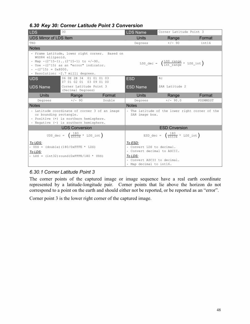
6.30.1 Corner Latitude Point 3
The corner points of the captured image or image sequence have a real earth coordinate
represented by a latitude-longitude pair. Corner points that lie above the horizon do not
correspond to a point on the earth and should either not be reported, or be reported as an “error”.
Corner point 3 is the lower right corner of the captured image.

49
6.31 Key 31: Corner Longitude Point 3 Conversion
LDS 31 LDS Name Corner Longitude Point 3
UDS Mirror of LDS Item Units Range Format TBD Degrees +/- 180 int16
Notes
- Frame Longitude, lower right corner. Based on WGS84 ellipsoid.
- Map -(2^15-1)..(2^15-1) to +/-180.
- Use -(2^15) as an "error" indicator.
- -(2^15) = 0x8000.
- Resolution: ~5.5 milli degrees.
LDS_dec = ( )LDS_rangeint_range * LDS_int
UDS 06 0E 2B 34 01 01 01 03 07 01 02 01 03 0D 01 00
ESD Rd
UDS Name Corner Longitude Point 3 (Decimal Degrees)
ESD Name SAR Longitude 2
Units Range Format Units Range Format Degrees +/- 180 Double Degrees +/- 180.0 PDDDMMSST
Notes Notes
- Longitude coordinate of corner 3 of an image or bounding rectangle.
- Positive (+) is eastern hemisphere.
- Negative (-) is western hemisphere.
- The longitude of the lower right corner of the SAR image box.
UDS Conversion ESD Cnversion
UDS_dec = ( )36065534 * LDS_int
To UDS:
- UDS = (double)(360/0xFFFE * LDS)
To LDS:
- LDS = (int32)round(0xFFFE/360 * UDS)
ESD_dec = ( )36065534 * LDS_int
To ESD:
- Convert LDS to decimal.
- Convert decimal to ASCII.
To LDS:
- Convert ASCII to decimal.
- Map decimal to int16.
6.31.1 Corner Longitude Point 3
The corner points of the captured image or image sequence have a real earth coordinate
represented by a latitude-longitude pair. Corner points that lie above the horizon do not
correspond to a point on the earth and should either not be reported, or be reported as an “error”.
Corner point 3 is the lower right corner of the captured image.

50
6.32 Key 32: Corner Latitude Point 4 Conversion
LDS 32 LDS Name Corner Latitude Point 4
UDS Mirror of LDS Item Units Range Format TBD Degrees +/- 90 int16
Notes
- Frame Latitude, lower left corner. Based on WGS84 ellipsoid.
- Map -(2^15-1)..(2^15-1) to +/-90.
- Use -(2^15) as an "error" indicator.
- -(2^15) = 0x8000.
- Resolution: ~2.7 milli degrees.
LDS_dec = ( )LDS_rangeint_range * LDS_int
UDS 06 0E 2B 34 01 01 01 03 07 01 02 01 03 0A 01 00
ESD Re
UDS Name Corner Latitude Point 4 (Decimal Degrees)
ESD Name SAR Latitude 3
Units Range Format Units Range Format Degrees +/- 90 Double Degrees +/- 90.0 PDDMMSST
Notes Notes
- Latitude coordinate of corner 4 of an image or bounding rectangle.
- Positive (+) is northern hemisphere.
- Negative (-) is southern hemisphere.
- The latitude of the lower left corner of the SAR image box.
UDS Conversion ESD Cnversion
UDS_dec = ( )18065534 * LDS_int
To UDS:
- UDS = (double)(180/0xFFFE * LDS)
To LDS:
- LDS = (int32)round(0xFFFE/180 * UDS)
ESD_dec = ( )18065534 * LDS_int
To ESD:
- Convert LDS to decimal.
- Convert decimal to ASCII.
To LDS:
- Convert ASCII to decimal.
- Map decimal to int16.
6.32.1 Corner Latitude Point 4
The corner points of the captured image or image sequence have a real earth coordinate
represented by a latitude-longitude pair. Corner points that lie above the horizon do not
correspond to a point on the earth and should either not be reported, or be reported as an “error”.
Corner point 4 is the lower left corner of the captured image.

51
6.33 Key 33: Corner Longitude Point 4 Conversion
LDS 33 LDS Name Corner Longitude Point 4
UDS Mirror of LDS Item Units Range Format TBD Degrees +/- 180 int16
Notes
- Frame Longitude, lower left corner. Based on WGS84 ellipsoid.
- Map -(2^15-1)..(2^15-1) to +/-180.
- Use -(2^151) as an "error" indicator.
- -(2^15) = 0x8000.
- Resolution: ~5.5 milli degrees.
LDS_dec = ( )LDS_rangeint_range * LDS_int
UDS 06 0E 2B 34 01 01 01 03 07 01 02 01 03 0E 01 00
ESD Rf
UDS Name Corner Longitude Point 4 (Decimal Degrees)
ESD Name SAR Longitude 3
Units Range Format Units Range Format Degrees +/- 180 Double Degrees +/- 180.0 PDDDMMSST
Notes Notes
- Longitude coordinate of corner 4 of an image or bounding rectangle.
- Positive (+) is eastern hemisphere.
- Negative (-) is western hemisphere.
- The longitude of the lower left corner of the SAR image box.
UDS Conversion ESD Cnversion
UDS_dec = ( )36065534 * LDS_int
To UDS:
- UDS = (double)(360/0xFFFE * LDS)
To LDS:
- LDS = (int32)round(0xFFFE/360 * UDS)
ESD_dec = ( )36065534 * LDS_int
To ESD:
- Convert LDS to decimal.
- Convert decimal to ASCII.
To LDS:
- Convert ASCII to decimal.
- Map decimal to int16.
6.33.1 Corner Longitude Point 4
The corner points of the captured image or image sequence have a real earth coordinate
represented by a latitude-longitude pair. Corner points that lie above the horizon do not
correspond to a point on the earth and should either not be reported, or be reported as an “error”.
Corner point 4 is the lower left corner of the captured image.

52
6.34 Key 34: Icing Detected Conversion
LDS 34 LDS Name Icing Detected
UDS Mirror of LDS Item Units Range Format TBD Icing Code 0..2 uint8
Notes
- Flag for icing detected at aircraft location.
- 0: Detector off
- 1: No icing Detected
- 2: Icing Detected
x
UDS Register ESD Id
UDS Name x ESD Name Icing Detected
Units Range Format Units Range Format x x x Icing Code 0..2 N
Notes Notes
- x - Output of the aircrafts icing detector
- 0: Detector off
- 1: No icing detected
- 2: Icing detected
UDS Conversion ESD Cnversion x
To UDS:
- x
To LDS:
- x
x
To ESD:
- Convert string to ID code.
To LDS:
- Convert ID code to string.
6.34.1 Icing Detected
This metadata item signals when the icing sensor detects water forming on its vibrating probe.

53
6.35 Key 35: Wind Direction Conversion
LDS 35 LDS Name Wind Direction
UDS Mirror of LDS Item Units Range Format TBD Degrees 0..360 uint16
Notes
- Wind direction at aircraft location.
- Map 0..(2^16-1) to 0..360.
- Resolution: ~5.5 milli degrees.
LDS_dec = ( )LDS_rangeuint_range * LDS_uint
UDS x ESD Wd
UDS Name x ESD Name Wind Direction
Units Range Format Units Range Format x x x Degrees 0..359 DDD
Notes Notes
- x - Direction (from North) from which the wind is blowing at the aircraft location
UDS Conversion ESD Cnversion x
To UDS:
- x
To LDS:
- x
ESD_dec = ( )36065534 * LDS_uint
To ESD:
- Convert LDS to decimal.
- Convert decimal to ASCII.
To LDS:
- Convert ESD ASCII to decimal.
- Map decimal to uint16.
6.35.1 Wind Direction
The direction the air body around the aircraft is traveling relative to true north.

54
6.36 Key 36: Wind Speed Conversion
LDS 36 LDS Name Wind Speed
UDS Mirror of LDS Item Units Range Format TBD Meters / Second 0..100 uint8
Notes
- Wind speed at aircraft location.
- Map 0..255 to 0..100 meters/second.
- 1 m/s = 1.94384449 knots.
- Resolution: ~0.4 meters / second.
LDS_dec = ( )LDS_rangeuint_range * LDS_uint
UDS x ESD Ws
UDS Name x ESD Name Wind Speed
Units Range Format Units Range Format x x x Knots 0..99 NN
Notes Notes
- x - Wind Speed (relative to the Earth) at the aircraft location.
UDS Conversion ESD Cnversion x
To UDS:
- x
To LDS:
- x
ESD_dec = ( )100255 * LDS_uint *
1.94384449knots 1m/s
To ESD:
- Convert LDS to decimal.
- Account for units.
- Convert knots to ASCII.
To LDS:
- Convert ESD ASCII to decimal.
- Account for units.
- Convert meters to uint8.
6.36.1 Wind Speed
The speed of the body of air that surrounds the aircraft relative to the ground is captured in this
wind speed metadata item.

55
6.37 Key 37: Static Pressure Conversion
LDS 37 LDS Name Static Pressure
UDS Mirror of LDS Item Units Range Format TBD Millibar 0..5000 uint16
Notes
- Static pressure at aircraft location.
- Map 0..(2^16-1) to 0..5000 mbar.
- 1 mbar = 0.0145037738 PSI.
- Resolution: ~0.08 Millibar
LDS_dec = ( )LDS_rangeuint_range * LDS_uint
UDS x ESD Ps
UDS Name x ESD Name Static Pressure
Units Range Format Units Range Format x x x PSI 0..99.99 DD.HH
Notes Notes
- x - Static Pressure
UDS Conversion ESD Cnversion x
To UDS:
- x
To LDS:
- x
ESD_dec = ( )500065535 * LDS_int *
0.0145037738 PSI1 mbar
To ESD:
- Convert LDS to decimal.
- Convert decimal to ASCII.
To LDS:
- Convert ESD ASCII to decimal.
- Map decimal to uint16.
6.37.1 Static Pressure
The static pressure is the pressure of the air that surrounds the aircraft. Static pressure is
measured by a sensor mounted out of the air stream on the side of the fuselage. This is used with
impact pressure to compute indicated airspeed, true airspeed, and density altitude.

56
6.38 Key 38: Density Altitude Conversion
LDS 38 LDS Name Density Altitude
UDS Mirror of LDS Item Units Range Format TBD Meters -900..19000 uint16
Notes
- Density altitude at aircraft location. Relative aircraft performance metric based on outside air temperature, static pressure, and humidity.
- Map 0..(2^16-1) to -900..19000 meters.
- Offset = -900.
- 1 meter = 3.2808399 feet.
- Resolution: ~0.3 meters.
LDS_dec = ( )LDS_rangeuint_range * LDS_int - Offset
UDS x ESD Da
UDS Name x ESD Name Density Altitude
Units Range Format Units Range Format x x x Feet +/- 99,999 PN
Notes Notes
- x - Density Altitude of the aircraft.
UDS Conversion ESD Cnversion x
To UDS:
- x
To LDS:
- x
ESD_dec = ( )1990065535*LDS_int-900 *
3.2808399 ft1 m
To ESD:
- Convert LDS to decimal.
- Account for units.
- Convert decimal to ASCII.
To LDS:
- Convert ESD ASCII to decimal.
- Account for units.
- Map decimal to uint16.
6.38.1 Density Altitude
Density altitude is the pressure altitude corrected for non-standard temperature variation.
Density altitude is a relative metric of the takeoff, climb, and other performance related
parameters of an aircraft.

57
6.39 Key 39: Outside Air Temperature Conversion
LDS 39 LDS Name Outside Air Temperature
UDS Mirror of LDS Item Units Range Format TBD Celcius -128..+127 int8
Notes
- Temperature outside of aircraft.
- -128..127 Degrees Celcius.
- Resolution: 1 degree celcius.
LDS_dec = LDS_int
UDS x ESD At
UDS Name x ESD Name Air Temperature
Units Range Format Units Range Format x x x Celcius +/- 99 PDD
Notes Notes
- x - Outside air temperature measured at the aircraft
UDS Conversion ESD Cnversion x
To UDS:
- x
To LDS:
- x
ESD_dec = LDS_int
To ESD:
- Convert int8 to string.
To LDS:
- Convert string to int8.
6.39.1 Outside Air Temperature
The measured temperature outside of the platform is captured in the outside air temperature
metadata item.
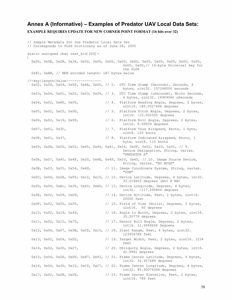
58
Annex A (Informative) – Examples of Predator UAV Local Data Sets:
EXAMPLE REQUIRES UPDATE FOR NEW CORNER POINT FORMAT (16 bits over 32)
// Sample Metadata for the Predator Local Data Set // Corresponds to PLDS Dictionary as of June 28, 2005 static unsigned char test_klv[205]= { 0x06, 0x0E, 0x2B, 0x34, 0x02, 0x00, 0x00, 0x00, 0x00, 0x00, 0x00, 0x00, 0x00, 0x00,
0x00, 0x00,// 16-byte Universal key for the PLDS
0x81, 0xBB, // BER encoded length: 187 bytes below //-key|length|Value----------------- 0x02, 0x04, 0x09, 0x5F, 0x6A, 0x00, // 2. UTC Time Stamp (Seconds), Seconds, 4
bytes, uint32. 157248000 seconds
0x03, 0x04, 0x01, 0x02, 0x03, 0x04, // 3. UTC Time Stamp (uSeconds), Micro Seconds, 4 bytes, uint32. 16909060 uSeconds
0x04, 0x02, 0x80, 0x00, // 4. Platform Heading Angle, Degrees, 2 bytes, uint16. 180.0027466 degrees
0x05, 0x02, 0xC0, 0x00, // 5. Platform Pitch Angle, Degrees, 2 bytes, int16. -10.000305 degrees
0x06, 0x02, 0x19, 0x99, // 6. Platform Roll Angle, Degrees, 2 bytes, int16. 9.99939 degrees
0x07, 0x01, 0x3C, // 7. Platform True Airspeed, Knots, 1 byte, uint8. 120 knots
0x08, 0x01, 0x37, // 8. Platform Indicated Airspeed, Knots, 1 byte, uint8. 110 knots
0x09, 0x0A, 0x50, 0x52, 0x45, 0x44, 0x41, 0x54, 0x4F, 0x52, 0x20, 0x41, // 9. Device Designation, String, varies. "PREDATOR A"
0x0A, 0x07, 0x45, 0x4F, 0x20, 0x4E, 0x4F, 0x53, 0x45, // 10. Image Source Device, String, varies. "EO NOSE"
0x0B, 0x03, 0x55, 0x54, 0x4D, // 11. Image Coordinate System, String, varies. "UTM"
0x0C, 0x04, 0x2E, 0xF6, 0x12, 0x10, // 12. Device Latitude, Degrees, 4 bytes, int32. 33.019603 degrees (ASI @ RB)
0x0D, 0x04, 0xAc, 0x35, 0x60, 0xA0, // 13. Device Longitude, Degrees, 4 bytes, int32. -117.095804 degrees
0x0E, 0x02, 0x59, 0xD9, // 14. Device Altitude, Feet, 2 bytes, uint16. 20000 feet
0x0F, 0x02, 0x55, 0x55, // 15. Field of View (Horiz), Degrees, 2 bytes, uint16. 60 degrees
0x10, 0x02, 0x19, 0x49, // 16. Angle to North, Degrees, 2 bytes, uint16. 35.55779 degrees
0x11, 0x02, 0x12, 0x7D, // 17. Sensor Roll Angle, Degrees, 2 bytes, int16. 12.9999694 Degrees
0x12, 0x04, 0x07, 0x5B, 0xCD, 0x15, // 18. Slant Range, Feet, 4 bytes, uint32. 123456789 feet
0x13, 0x02, 0x04, 0xD2, // 19. Target Width, Feet, 2 bytes, uint16. 1234 feet
0x14, 0x02, 0x3D, 0x27, // 20. Obliquity Angle, Degrees, 2 bytes, int16. 42.9991 degrees
0x15, 0x04, 0x2E, 0xDF, 0x87, 0x43, // 21. Frame Center Latitude, Degrees, 4 bytes, int32. 32.957689 degrees
0x16, 0x04, 0x3D, 0x15, 0xC0, 0xC7, // 22. Frame Center Longitude, Degrees, 4 bytes, int32. 85.90074304 degrees
0x17, 0x02, 0x0E, 0xCE, // 23. Frame Center Elevation, Feet, 2 bytes, uint16. 789 feet

59
0x18, 0x04, 0x2E, 0xDF, 0x87, 0x43, // 24. Corner Latitude Point 1, Degrees, 4 bytes, int32. 32.957689 degrees (ASI @ Saber Springs)
0x19, 0x04, 0xC2, 0xEA, 0x3F, 0x35, // 25. Corner Longitude Point 1, Degrees, 4 bytes, int32. -85.900743374 degrees
0x1A, 0x04, 0x2E, 0xDF, 0x87, 0x43, // 26. Corner Latitude Point 2, Degrees, 4 bytes, int32. 32.957689 degrees (ASI @ Saber Springs)
0x1B, 0x04, 0x53, 0x44, 0xA3, 0xFD, // 27. Corner Longitude Point 2, Degrees, 4 bytes, int32. 117.09580402 degrees
0x1C, 0x04, 0x2E, 0xDF, 0x87, 0x43, // 28. Corner Latitude Point 3, Degrees, 4 bytes, int32. 32.957689 degrees (ASI @ Saber Springs)
0x1D, 0x04, 0xAC, 0xBB, 0x9F, 0x60, // 29. Corner Longitude Point 3, Degrees, 4 bytes, int32. -117.09580402 degrees
0x1E, 0x04, 0x2E, 0xDF, 0x87, 0x43, // 30. Corner Latitude Point 4, Degrees, 4 bytes, int32. 32.957689 degrees (ASI @ Saber Springs)
0x1F, 0x04, 0xA8, 0x35, 0x60, 0xA0, // 31. Corner Longitude Point 4, Degrees, 4 bytes, int32. -123.456789 degrees
0x20, 0x01, 0x01, // 32. Icing Detected, Code, 1 byte, uint8. code 1: no icing detected
0x21, 0x02, 0x40, 0x00, // 33. Wind Direction, Degrees, 2 bytes, int16. 90.00137 degrees.
0x22, 0x01, 0x0F, // 34. Wind Speed, Knots, 1 byte, uint8. 15 Knots
0x23, 0x02, 0x19, 0x9A, // 35. Static Pressure, PSI, 2 bytes, uint16. 10.00076 PSI
0x24, 0x02, 0x59, 0xED, // 36. Density Altitude, Feet, 2 bytes, uint16. 20020 Feet
0x25, 0x01, 0xA3, // 37. Outside Air Temperature, Celcius, 1 byte, int8. -35 degrees
0x01, 0x02, 0x09, 0xB2 // 1. Checksum, binary, 2 bytes, uint16. 0x163F = 5695
};// end of test_klv
Related Documents