IMPROVED UAV DATALINK PERFORMANCE USING EMBEDDED ANTENNAS Kavindra Krishna & Amit Kumar Aligarh Muslim University Aligarh, INDIA ABSTRACT UAVs are generally an order of magnitude less expensive and smaller than piloted vehicles, but still must possess air vehicle essentials such as propulsion, flight control, and payload. Antennas used for communication, navigation and mission function present unique challenges because they generally cannot be reduced in size without degradation in electrical performance or increase in weight. Typical UAV telemetry systems operate at UHF or L-band frequencies and employ blade antennas that mount on the fuselage exterior and protrude many inches into the air stream. These parasitic antennas degrade aerodynamics, increase drag, increase weight, usually provide less than optimal antenna performance because of blockage by surrounding structure, and are prone to physical damage due to its obstructive locations. These problems can be largely eliminated by embedding antennas into existing composite structures on the UAV, such as wings or stabilizers. Such antennas have been embedded in UAV flight control structures and have demonstrated improved RF performance, lower weight and lower total cost compared to conventional blade antennas. This paper presents results of the antenna demonstration program, including details of the design, integration, manufacture, and electrical test results. KEY WORDS: Antenna, Radome, Unmanned Air Vehicle, Data Link 1. INTRODUCTION The UAV industry presents a rapidly emerging market as potential users continue to understand and realize the benefits of using unmanned vehicles for carrying out dull, dirty, or dangerous missions. The cost pressures and competitive landscape in the UAV community creates new demands for advanced composite structures, and specifically new opportunities for multi- functional composites. Multi-functional composites are assemblies that simultaneously serve multiple functions, such as structural and electrical (e.g., antennas and other sensors). The antennas described in this paper demonstrate that a UAV platform is an ideal application for incorporating multi-functional composites, specifically combining structure plus electrical radio frequency (RF) functions. 1.1 UAV CHALLENGES Developers of UAVs face a number of design challenges. First, the vehicle must have many features of conventional piloted aircraft, such as flight control, propulsion and payload; however, the vehicle must also be significantly less expensive than conventional aircraft. With the numerous competing platforms in development, cost is invariably a primary design consideration. 1

Welcome message from author
This document is posted to help you gain knowledge. Please leave a comment to let me know what you think about it! Share it to your friends and learn new things together.
Transcript
IMPROVED UAV DATALINK PERFORMANCE USING
EMBEDDED ANTENNAS
Kavindra Krishna & Amit Kumar Aligarh Muslim University
Aligarh, INDIA
ABSTRACT
UAVs are generally an order of magnitude less expensive and smaller than piloted vehicles, but
still must possess air vehicle essentials such as propulsion, flight control, and payload. Antennas
used for communication, navigation and mission function present unique challenges because
they generally cannot be reduced in size without degradation in electrical performance or
increase in weight. Typical UAV telemetry systems operate at UHF or L-band frequencies and
employ blade antennas that mount on the fuselage exterior and protrude many inches into the air
stream. These parasitic antennas degrade aerodynamics, increase drag, increase weight, usually
provide less than optimal antenna performance because of blockage by surrounding structure,
and are prone to physical damage due to its obstructive locations. These problems can be largely
eliminated by embedding antennas into existing composite structures on the UAV, such as wings
or stabilizers. Such antennas have been embedded in UAV flight control structures and have
demonstrated improved RF performance, lower weight and lower total cost compared to
conventional blade antennas. This paper presents results of the antenna demonstration program,
including details of the design, integration, manufacture, and electrical test results. KEY WORDS: Antenna, Radome, Unmanned Air Vehicle, Data Link
1. INTRODUCTION
The UAV industry presents a rapidly emerging market as potential users continue to understand
and realize the benefits of using unmanned vehicles for carrying out dull, dirty, or dangerous
missions. The cost pressures and competitive landscape in the UAV community creates new
demands for advanced composite structures, and specifically new opportunities for multi-
functional composites. Multi-functional composites are assemblies that simultaneously serve
multiple functions, such as structural and electrical (e.g., antennas and other sensors). The
antennas described in this paper demonstrate that a UAV platform is an ideal application for
incorporating multi-functional composites, specifically combining structure plus electrical radio
frequency (RF) functions. 1.1 UAV CHALLENGES Developers of UAVs face a number of design challenges. First, the
vehicle must have many features of conventional piloted aircraft, such as flight control,
propulsion and payload; however, the vehicle must also be significantly less expensive than
conventional aircraft. With the numerous competing platforms in development, cost is invariably
a primary design consideration.
1
Second, the UAV community has a background unlike piloted aircraft. Small UAV platforms
resemble an evolutionary product from radio-controlled hobby planes. As such, many UAV
developers have similar origins and are typically not RF or antenna experts. Antennas and
payloads are vehicle afterthoughts and not primary design considerations. Consequently,
antenna performance typically suffers due to interference with the airframe, non-optimum
antenna location or improper selection of components. Ultimately, data link efficiency and
mission success are less than optimal. Finally, UAVs must be both light weight and damage tolerant, which are typically conflicting
goals. The light duty propulsion system is only capable of carrying the essential payload
components and a minimally designed composite airframe. UAVs must also be highly damage
tolerant, as many of these vehicles are launched from trucks, trailers, runways, manually, and
other rugged environments and can land on rough terrain or even in water. For these lightweight
vehicles to sustain these operating environment loads, efforts must be made to reduce parasitic
components, such as antennas. With these challenges, UAV developers require an increased
level of component integration to satisfy their cost, weight, performance, and mission goals.
This need has created a new application for multi-functional composites. 1.2 MULTI-FUNCTIONAL COMPOSITES The notion of incorporating multiple functions
within a single composite structure has existed for many years. Piezo-electro materials, electro-
rheological fluids, load monitoring devices, and many other types of sensors have been
successfully embedded within composite structures. Applications have included structure health
monitoring, shape altering, dampening, stiffening, RF integration and others. For many reasons,
these embedded technologies have been slow to become qualified on production platforms and
programs. One reason for the slow acceptance of multi-functional composites on aircraft is perceived
technical risk. There is a technical uncertainty with disrupting the continuity of a composite
structure with an embedded device. Terminating composite plies, changing material properties
across a section, and adding electrical or thermal connectivity devices to a structure all create
new variables regarding structural performance and long term survivability. Significant costs
must be expended to understand, quantify, and address these issues. Prior to UAVs, there have
been few applications that provided sufficient justification to resolve these issues. Compared to
piloted vehicles, UAVs have less stringent qualification requirements and the composite
technology employed is more basic. UAV platforms are ideal applications to exploit
multifunctional composites. Development of multi-functional composites on UAVs is expected
to accelerate their acceptance on piloted vehicles and for other harsh environments.
2. CURRENT TECHNOLOGY
To fully appreciate the benefits of a multi-functional UAV composite structure with an
embedded antenna, a full assessment of the current technology is necessary. The current
technology is explained by first considering blade antennas that are routinely employed in data
link applications. Next, a detailed explanation of the composite construction of a typical UAV is
provided. The explanation pertains to flight control surfaces, such as wings and stabilizers, as
these are the components from which the embedded antenna demonstrator units were produced. 2
The specific processes and materials are presented with the mechanical integration
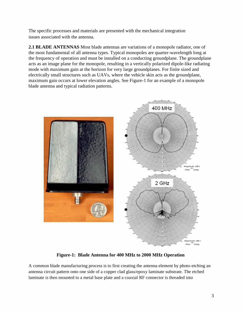
issues associated with the antenna. 2.1 BLADE ANTENNAS Most blade antennas are variations of a monopole radiator, one of
the most fundamental of all antenna types. Typical monopoles are quarter-wavelength long at
the frequency of operation and must be installed on a conducting groundplane. The groundplane
acts as an image plane for the monopole, resulting in a vertically polarized dipole-like radiating
mode with maximum gain at the horizon for very large groundplanes. For finite sized and
electrically small structures such as UAVs, where the vehicle skin acts as the groundplane,
maximum gain occurs at lower elevation angles. See Figure-1 for an example of a monopole
blade antenna and typical radiation patterns.
Figure-1: Blade Antenna for 400 MHz to 2000 MHz Operation
A common blade manufacturing process is to first creating the antenna element by photo-etching an
antenna circuit pattern onto one side of a copper clad glass/epoxy laminate substrate. The etched
laminate is then mounted to a metal base plate and a coaxial RF connector is threaded into 3
the base plate and soldered to the printed circuit board element. The element is covered with an
aerodynamically shaped composite radome. The base plate has mounting holes to secure the
antenna to the vehicle using nuts and bolts or other similar mechanical hardware. After
mounting, the connector passes through an opening in the aircraft skin and the radome protrudes
away from the vehicle and into air stream. 2.2 UAV FABRICATION AND MATERIALS The materials and processes used for typical
UAVs are consistent with the overall low cost vehicle design goal. Material composition is
generally foam or balsa core wrapped with composite skins. The skins are glass or carbon fiber
cloth impregnated with epoxy resin. In some designs, glass fiber is used for a majority of the
structure and carbon is used for local stiffening, such as for a wing spar. The skins are either
prepreg or dry cloth impregnated via a wet lay-up method. An alternative to using core as a light
density filler is using an assembled structure of composite spars and ribs. To produce the UAV flight control surfaces, the cavity filler can be either CNC machined or
prefabricated and assembled. For prepreg composite skins, the skins are pre-cured and
subsequently wrapped around the light density filler and bonded in place. Wet lay-up skins are
either pre-cured or laminated directly around the machined foam. The skins are generally 2-4
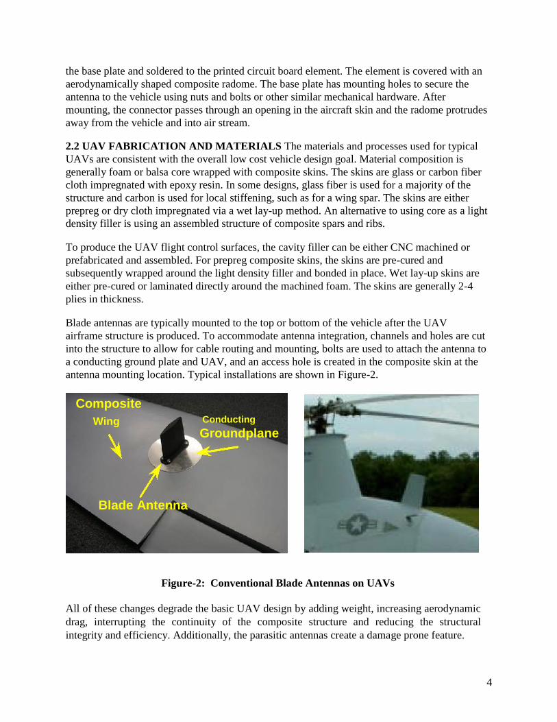
plies in thickness. Blade antennas are typically mounted to the top or bottom of the vehicle after the UAV
airframe structure is produced. To accommodate antenna integration, channels and holes are cut
into the structure to allow for cable routing and mounting, bolts are used to attach the antenna to
a conducting ground plate and UAV, and an access hole is created in the composite skin at the
antenna mounting location. Typical installations are shown in Figure-2.
Composite
Wing Conducting Groundplane
Blade Antenna
Figure-2: Conventional Blade Antennas on UAVs
All of these changes degrade the basic UAV design by adding weight, increasing aerodynamic
drag, interrupting the continuity of the composite structure and reducing the structural
integrity and efficiency. Additionally, the parasitic antennas create a damage prone feature.
4
Since blade antennas on UAVs are usually incorporated after the vehicle is produced, antenna
performance is generally less than optimal. Antenna gain and radiation pattern are degraded by
the air vehicle, particularly if carbon fiber is used on the UAV. The pattern orientation relative
to the target may not be optimal due to the location of the antenna on the vehicle. Considering
antenna location at the end of the design process limits the possible locations for the antenna,
which compromises RF system performance. All of these issues associated with current UAV antenna integration and technology suggest
that the antenna functions should be included as an initial design consideration and designed
into the composite structure. These issues are the motivating factors that lead to the
development of the two demonstration units described in the next sections.
3. MULTI-FUNCTIONAL UAV WING
The first multi-functional composite structure demonstrator presented consists of a UAV wing
with a slot antenna integrated into the wing underside. A UAV wing was modified by removing
the existing blade antenna, installing a flush mounted slot antenna in the same location, and then
testing the antenna for RF radiation pattern and gain performance. Descriptions of the antenna
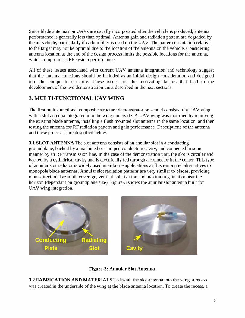
and these processes are described below. 3.1 SLOT ANTENNA The slot antenna consists of an annular slot in a conducting
groundplane, backed by a machined or stamped conducting cavity, and connected in some
manner by an RF transmission line. In the case of the demonstration unit, the slot is circular and
backed by a cylindrical cavity and is electrically fed through a connector in the center. This type
of annular slot radiator is widely used in airborne applications as flush-mounted alternatives to
monopole blade antennas. Annular slot radiation patterns are very similar to blades, providing
omni-directional azimuth coverage, vertical polarization and maximum gain at or near the
horizon (dependant on groundplane size). Figure-3 shows the annular slot antenna built for
UAV wing integration.
Conducting Radiating
Cavity
Plate Slot
Figure-3: Annular Slot Antenna
3.2 FABRICATION AND MATERIALS To install the slot antenna into the wing, a recess
was created in the underside of the wing at the blade antenna location. To create the recess, a
5
circular piece of the composite skin was first removed. The diameter of the removed section was
slightly larger than the antenna and the location was centered on the location of the existing
blade antenna. With the skin removed, a circular recess was machined into the foam core to
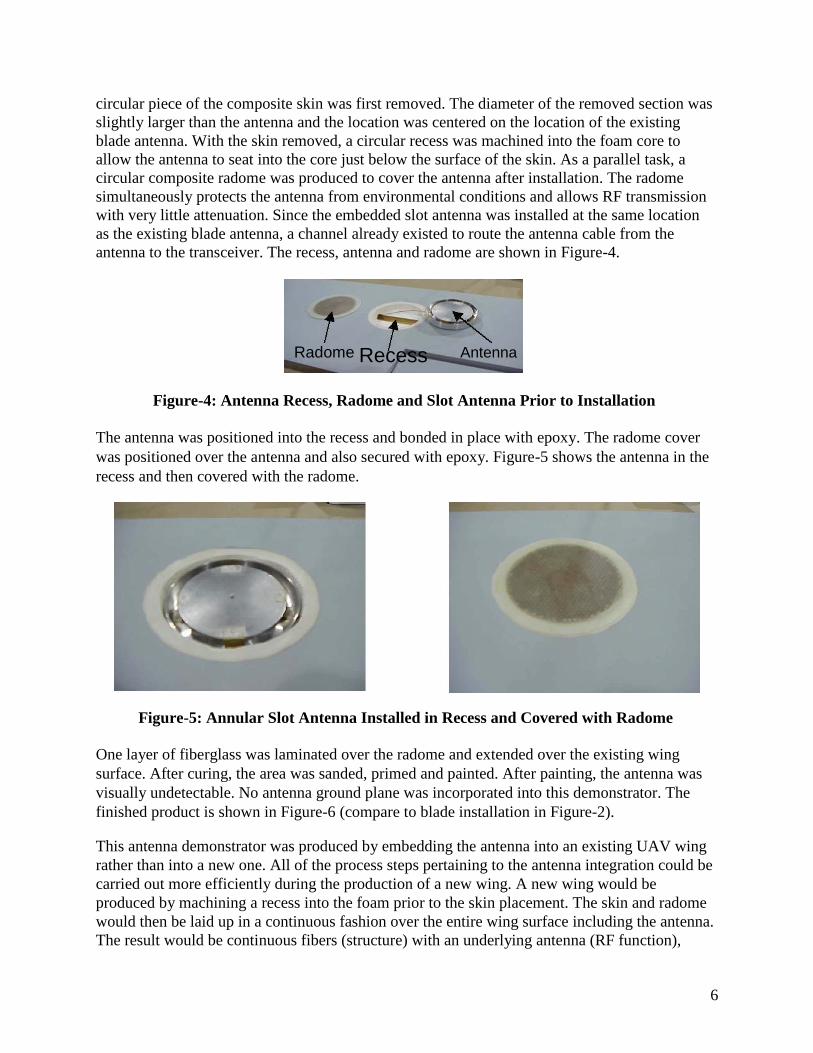
allow the antenna to seat into the core just below the surface of the skin. As a parallel task, a
circular composite radome was produced to cover the antenna after installation. The radome
simultaneously protects the antenna from environmental conditions and allows RF transmission
with very little attenuation. Since the embedded slot antenna was installed at the same location
as the existing blade antenna, a channel already existed to route the antenna cable from the
antenna to the transceiver. The recess, antenna and radome are shown in Figure-4.
Radome Recess Antenna
Figure-4: Antenna Recess, Radome and Slot Antenna Prior to Installation
The antenna was positioned into the recess and bonded in place with epoxy. The radome cover
was positioned over the antenna and also secured with epoxy. Figure-5 shows the antenna in the
recess and then covered with the radome.
Figure-5: Annular Slot Antenna Installed in Recess and Covered with Radome
One layer of fiberglass was laminated over the radome and extended over the existing wing
surface. After curing, the area was sanded, primed and painted. After painting, the antenna was
visually undetectable. No antenna ground plane was incorporated into this demonstrator. The
finished product is shown in Figure-6 (compare to blade installation in Figure-2). This antenna demonstrator was produced by embedding the antenna into an existing UAV wing
rather than into a new one. All of the process steps pertaining to the antenna integration could be
carried out more efficiently during the production of a new wing. A new wing would be
produced by machining a recess into the foam prior to the skin placement. The skin and radome
would then be laid up in a continuous fashion over the entire wing surface including the antenna.
The result would be continuous fibers (structure) with an underlying antenna (RF function),
6
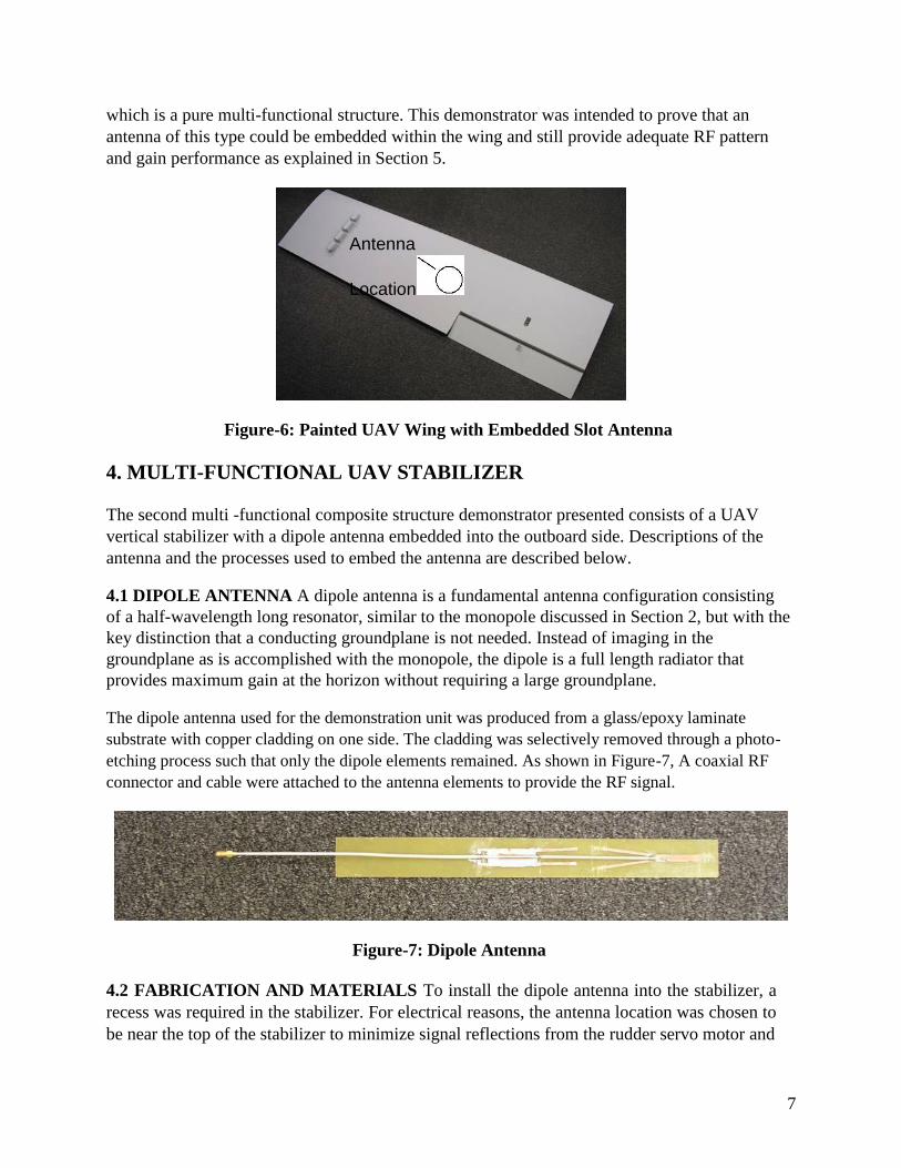
which is a pure multi-functional structure. This demonstrator was intended to prove that an
antenna of this type could be embedded within the wing and still provide adequate RF pattern
and gain performance as explained in Section 5.
Antenna
Location
Figure-6: Painted UAV Wing with Embedded Slot Antenna
4. MULTI-FUNCTIONAL UAV STABILIZER
The second multi -functional composite structure demonstrator presented consists of a UAV
vertical stabilizer with a dipole antenna embedded into the outboard side. Descriptions of the
antenna and the processes used to embed the antenna are described below. 4.1 DIPOLE ANTENNA A dipole antenna is a fundamental antenna configuration consisting
of a half-wavelength long resonator, similar to the monopole discussed in Section 2, but with the
key distinction that a conducting groundplane is not needed. Instead of imaging in the
groundplane as is accomplished with the monopole, the dipole is a full length radiator that
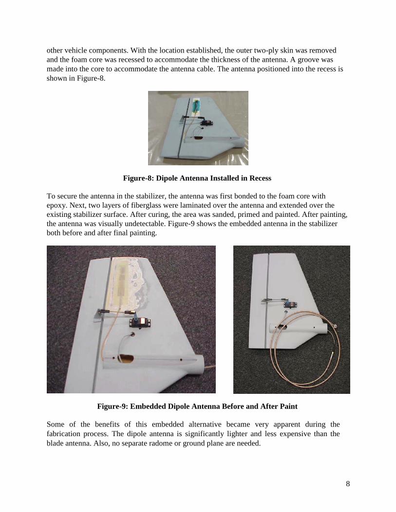
provides maximum gain at the horizon without requiring a large groundplane. The dipole antenna used for the demonstration unit was produced from a glass/epoxy laminate
substrate with copper cladding on one side. The cladding was selectively removed through a photo-
etching process such that only the dipole elements remained. As shown in Figure-7, A coaxial RF
connector and cable were attached to the antenna elements to provide the RF signal.
Figure-7: Dipole Antenna
4.2 FABRICATION AND MATERIALS To install the dipole antenna into the stabilizer, a
recess was required in the stabilizer. For electrical reasons, the antenna location was chosen to
be near the top of the stabilizer to minimize signal reflections from the rudder servo motor and 7
other vehicle components. With the location established, the outer two-ply skin was removed
and the foam core was recessed to accommodate the thickness of the antenna. A groove was
made into the core to accommodate the antenna cable. The antenna positioned into the recess is
shown in Figure-8.
Figure-8: Dipole Antenna Installed in Recess
To secure the antenna in the stabilizer, the antenna was first bonded to the foam core with
epoxy. Next, two layers of fiberglass were laminated over the antenna and extended over the
existing stabilizer surface. After curing, the area was sanded, primed and painted. After painting,
the antenna was visually undetectable. Figure-9 shows the embedded antenna in the stabilizer
both before and after final painting.
Figure-9: Embedded Dipole Antenna Before and After Paint
Some of the benefits of this embedded alternative became very apparent during the
fabrication process. The dipole antenna is significantly lighter and less expensive than the
blade antenna. Also, no separate radome or ground plane are needed.
8
This demonstrator was also produced by embedding the antenna into an existing UAV stabilizer
rather than into a new one. All of the process steps pertaining to the antenna integration could be
carried out more efficiently during the production of a new stabilizer. A new stabilizer would be
produced by machining a shallow recess into the foam prior to the skin placement. The skin and
antenna would then be laid up in a continuous fashion over the entire stabilizer surface including
the antenna. The lay-up process would include embedding the antenna between composite plies.
The result would be continuous fibers (structure) surrounding an embedded antenna (RF
function), which is a pure multi -functional structure. This demonstrator was intended to prove
that an antenna of this type can be embedded in the stabilizer and still provide adequate RF
pattern and gain performance as explained in Section 5.
5. ANTENNA PERFORMANCE
The primary goal of this project was to demonstrate that data link antennas can be embedded
within various UAV structures and that RF performance can be equal to or better than their
traditional blade antenna counterpart. After fabrication, the embedded antennas were tested for
pattern and gain and the results were compared to the blade antenna. The antenna testing and
results are described in the following sections. 5.1 ANTENNA TESTING
The antennas evaluated in this project were L-Band antennas designed to operate from 1700-
1900 MHz for Line-of-Sight (LOS) communications of voice or data. To support this, the
antenna radiation pattern must be omni-directional in the azimuth plane and provide
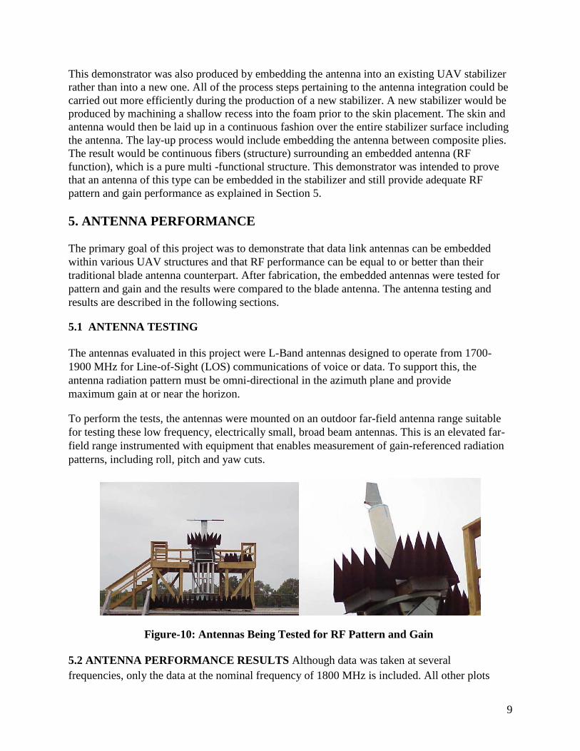
maximum gain at or near the horizon. To perform the tests, the antennas were mounted on an outdoor far-field antenna range suitable
for testing these low frequency, electrically small, broad beam antennas. This is an elevated far-
field range instrumented with equipment that enables measurement of gain-referenced radiation
patterns, including roll, pitch and yaw cuts.
Figure-10: Antennas Being Tested for RF Pattern and Gain
5.2 ANTENNA PERFORMANCE RESULTS Although data was taken at several
frequencies, only the data at the nominal frequency of 1800 MHz is included. All other plots 9
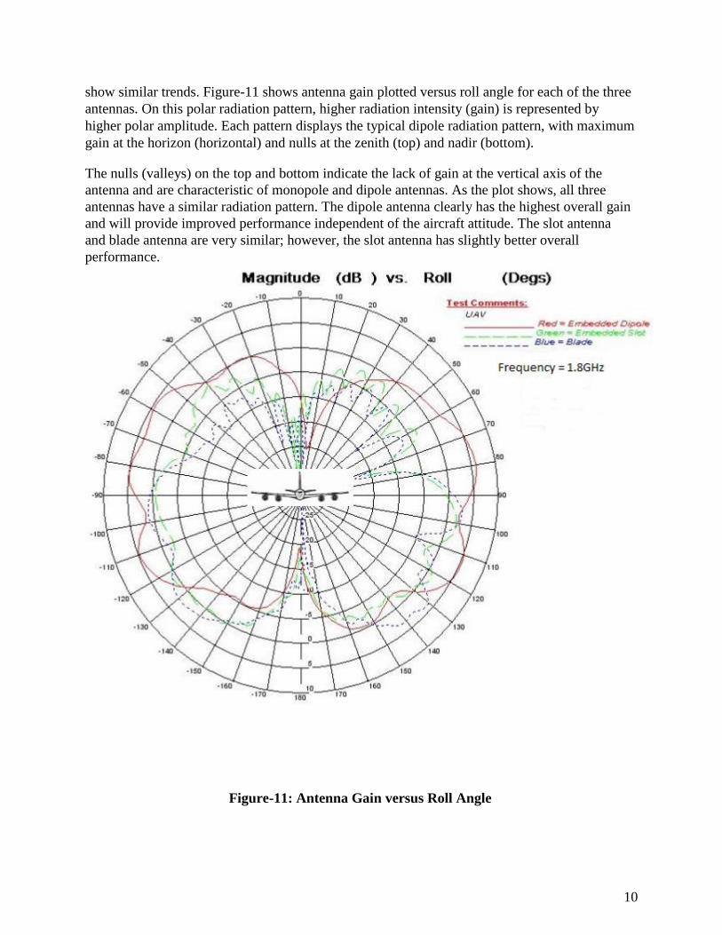
show similar trends. Figure-11 shows antenna gain plotted versus roll angle for each of the three
antennas. On this polar radiation pattern, higher radiation intensity (gain) is represented by
higher polar amplitude. Each pattern displays the typical dipole radiation pattern, with maximum
gain at the horizon (horizontal) and nulls at the zenith (top) and nadir (bottom). The nulls (valleys) on the top and bottom indicate the lack of gain at the vertical axis of the
antenna and are characteristic of monopole and dipole antennas. As the plot shows, all three
antennas have a similar radiation pattern. The dipole antenna clearly has the highest overall gain
and will provide improved performance independent of the aircraft attitude. The slot antenna
and blade antenna are very similar; however, the slot antenna has slightly better overall
performance.
Figure-11: Antenna Gain versus Roll Angle 10
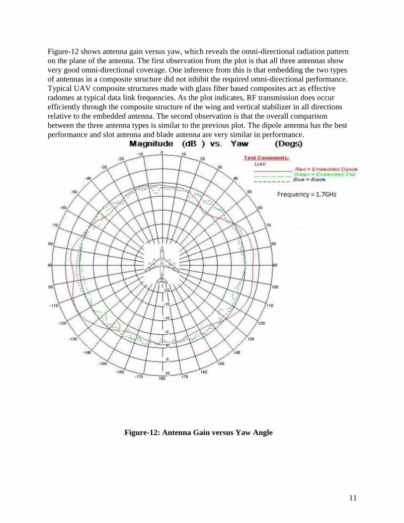
Figure-12 shows antenna gain versus yaw, which reveals the omni-directional radiation pattern
on the plane of the antenna. The first observation from the plot is that all three antennas show
very good omni-directional coverage. One inference from this is that embedding the two types
of antennas in a composite structure did not inhibit the required omni-directional performance.
Typical UAV composite structures made with glass fiber based composites act as effective
radomes at typical data link frequencies. As the plot indicates, RF transmission does occur
efficiently through the composite structure of the wing and vertical stabilizer in all directions
relative to the embedded antenna. The second observation is that the overall comparison
between the three antenna types is similar to the previous plot. The dipole antenna has the best
performance and slot antenna and blade antenna are very similar in performance.
Figure-12: Antenna Gain versus Yaw Angle
11
7. CONCLUSIONS
This paper describes the design, development and test of two demonstration units consisting of
multi-functional UAV composite structures containing embedded antennas. These demonstrators
were motivated by three factors. First, UAV developers face many technical and cost challenges
as the demands for their vehicles continue to accelerate. Second, multi-functional composites are
structures that are intuitively beneficial, but their application and potential has only begun to be
realized. Third, the current data link function on UAVs, as carried out by conventional blade
antennas, is less than optimal. The two demonstration units clearly show that there are data link antenna alternatives for UAV
developers as they continue their vehicle development and design new vehicles. The first
demonstrator was a UAV wing with an annular slot antenna embedded on the underside. The
second was a vertical stabilizer with a dipole antenna embedded in the outboard surface of the
stabilizer. The units were produced and tested. The test results were compared to the
performance of a conventional blade antenna. The antenna pattern and gain performance of the embedded antennas was equal to or better than
the current blade antenna. The dipole antenna was notably superior to the blade antenna and the
annular slot antenna was marginally better. The results of this paper should motivate UAV
developers to consider these alternatives as they continue to develop their vehicles. The results
should also help accelerate the acceptance and incorporation of multi-functional composite
structures into new applications.
12
Related Documents