© 2012 Alamo Group Inc. 1165 & 1465 Published 03/12 Part No. 4353C OPERATOR’S MANUAL 1020 S. Sangamon Ave. Gibson City, IL 60936 800-446-5158 E-mail: [email protected] TILLAGE This Operator's Manual is an integral part of the safe operation of this machine and must be maintained with the unit at all times. READ, UNDERSTAND, and FOLLOW the Safety and Operation Instructions contained in this manual before operating the equipment. C01- Cover $0.00

Welcome message from author
This document is posted to help you gain knowledge. Please leave a comment to let me know what you think about it! Share it to your friends and learn new things together.
Transcript
© 2012 Alamo Group Inc.
1165 & 1465
Published 03/12 Part No. 4353C
OPERATOR’S MANUAL
1020 S. Sangamon Ave.Gibson City, IL 60936800-446-5158E-mail: [email protected]
TILLAGE
This Operator's Manual is an integral part of the safe operation of this machine and mustbe maintained with the unit at all times. READ, UNDERSTAND, and FOLLOW the Safetyand Operation Instructions contained in this manual before operating the equipment. C01-Cover
$0.00

To the Owner/Operator/Dealer
All implements with moving parts are potentially hazardous. There is no substitute for a cautious, safe-mindedoperator who recognizes the potential hazards and follows reasonable safety practices. The manufacturer hasdesigned this implement to be used with all its safety equipment properly attached to minimize the chance ofaccidents.
BEFORE YOU START! Read the safety messages on the implement and shown in your manual. Observe the rulesof safety and common sense!
WARRANTY INFORMATION:
Read and understand the complete Warranty Statement found in this Manual. Fill out the Warranty RegistrationForm in full and return it to within 30 Days. Make certain the Serial Number of the Machine is recorded on theWarranty Card and on the Warranty Form that you retain.
TABLE OF CONTENTS
SAFETY SECTION ............................................................................................................... 1-1
General Safety Instructions and Practices..........................................................................................................1-2Operator Safety Instructions and Practices ........................................................................................................1-3Equipment Operation Safety Instructions and Practices.....................................................................................1-5Connecting or Disconnecting Implement Safety Instructions and Practices.......................................................1-8Maintenance and Service Safety Instructions and Practices ..............................................................................1-8Transporting Safety Instructions and Practices ................................................................................................1-10Concluding Safety Instructions and Practices...................................................................................................1-12Decal Location ..................................................................................................................................................1-13Decals ...............................................................................................................................................................1-15Federal Laws and Regulations .........................................................................................................................1-20
INTRODUCTION SECTION.................................................................................................. 2-1
ASSEMBLY SECTION ......................................................................................................... 3-1
TRACTOR PREPARATION................................................................................................................................3-2CONNECTING CHISEL BAR TO DISC..............................................................................................................3-3DISC DEPTH SETTING......................................................................................................................................3-3CHISEL DEPTH SETTING .................................................................................................................................3-4DISC FRAME SET-UP........................................................................................................................................3-4Safety Reflector Attachment .............................................................................................................................3-14
OPERATION SECTION........................................................................................................ 4-1
Standard Equipment and Specifications .............................................................................................................4-3OPERATOR REQUIREMENTS..........................................................................................................................4-4TRACTOR REQUIREMENTS.............................................................................................................................4-5ROPS and Seat Belt ...........................................................................................................................................4-5Tractor Safety Devices........................................................................................................................................4-5Tractor Horsepower ............................................................................................................................................4-53-Point Hitch .......................................................................................................................................................4-6Front End Weight ................................................................................................................................................4-6GETTING ON AND OFF THE TRACTOR ..........................................................................................................4-6Boarding the Tractor ...........................................................................................................................................4-7Dismounting the Tractor......................................................................................................................................4-7STARTING THE TRACTOR ...............................................................................................................................4-8CONNECTING THE IMPLEMENT TO THE TRACTOR .....................................................................................4-8Safety Tow Chain................................................................................................................................................4-9SETTING THE IMPLEMENT ............................................................................................................................4-10Disc Frame Leveling .........................................................................................................................................4-10Disc Gang Angle Setting...................................................................................................................................4-11Chisel Trip Shanks............................................................................................................................................4-11PRE-OPERATION INSPECTION AND SERVICE............................................................................................4-12Tractor Pre-Operation Inspection/Service.........................................................................................................4-13Implement Pre-Operation Inspection/Service ...................................................................................................4-13DRIVING THE TRACTOR AND IMPLEMENT..................................................................................................4-15OPERATING THE TRACTOR AND IMPLEMENT............................................................................................4-15Foreign Debris Hazards ....................................................................................................................................4-16Bystanders/Passersby Precautions ..................................................................................................................4-16Engaging the Power Take Off (PTO) ................................................................................................................4-17PTO RPM and Ground Speed ..........................................................................................................................4-17
Operating the Implement ..................................................................................................................................4-18Ball Valve Operation .........................................................................................................................................4-18Using Chisel Bar on Tractor 3-Point Hitch ........................................................................................................4-18Chisel Bar Gauge Wheels.................................................................................................................................4-19Chisel Bar Coulters ...........................................................................................................................................4-19Shutting Down the Implement ...........................................................................................................................4-19DISCONNECTING THE IMPLEMENT FROM THE TRACTOR........................................................................4-19IMPLEMENT STORAGE ..................................................................................................................................4-20TRANSPORTING THE TRACTOR AND IMPLEMENT ....................................................................................4-20DRIVING THE TRACTOR AND IMPLEMENT..................................................................................................4-21Transporting or Servicing..................................................................................................................................4-22Brake and Differential Lock Setting...................................................................................................................4-23Transporting on Public Roadways ....................................................................................................................4-24
MAINTENANCE SECTION................................................................................................... 5-1
GENERAL MAINTENANCE................................................................................................................................5-2PROPER TORQUE CHART FOR FASTENERS................................................................................................5-2TO THE OWNER/OPERATOR/DEALER............................................................................................................1-2

Safety Section 1-1
SAFETY SECTION

SAFETYS
AF
ET
Y
General Safety Instructions and PracticesA careful operator is the best operator. Safety is of primary importance to the manufacturer and should be tothe owner/operator. Most accidents can be avoided by being aware of your equipment, your surroundings, andobserving certain precautions. The first section of this manual includes a list of Safety Messages that, iffollowed, will help protect the operator and bystanders from injury or death. Read and understand these SafetyMessages before assembling, operating or servicing this Implement. This equipment should only be operatedby those persons who have read the manual, who are responsible and trained, and who know how to do soresponsibly.
The Safety Alert Symbol combined with a Signal Word, as seen below, is used throughout thismanual and on decals which are attached to the equipment. The Safety Alert Symbol means:“ATTENTION! BECOME ALERT! YOUR SAFETY IS INVOLVED!” The Symbol and Signal Wordare intended to warn the owner/operator of impending hazards and the degree of possible injuryfaced when operating this equipment.
Indicates an imminently hazardous situation that, if not avoided, WILL result in DEATH ORVERY SERIOUS INJURY.
Indicates an imminently hazardous situation that, if not avoided, COULD result in DEATHOR SERIOUS INJURY.
Indicates an imminently hazardous situation that, if not avoided, MAY result in MINORINJURY.
Identifies special instructions or procedures that, if not strictly observed, could result indamage to, or destruction of the machine, attachments or the environment.
NOTE: Identifies points of particular interest for more efficient and convenient operation or repair.(SG-1)
Practice all usual and customary safe working precautions and above all---remember safety isup to YOU. Only YOU can prevent serious injury or death from unsafe practices.
READ, UNDERSTAND, and FOLLOW the following Safety Messages. Serious injury ordeath may occur unless care is taken to follow the warnings and instructions stated in theSafety Messages. Always use good common sense to avoid hazards. (SG-2)
Si no lee ingles, pida ayuda a alguien que si lo lea para que le traduzca lasmedidas de seguridad. (SG-3)
1165/1465 03/12 Safety Section 1-2
© 2012 Alamo Group Inc.

SAFETYS
AF
ET
Y
Operator Safety Instructions and Practices
Engine Exhaust, some of its constituents, and certain vehicle components contain or emitchemicals known to the state of California to cause cancer and birth defects or otherreproductive harm. (SG-30)
Battery posts, terminals and related accessories contain lead and lead compounds,chemicals known to the state of California to cause cancer, birth defects or otherreproductive harm. (SG-31)
There are obvious and hidden potential hazards in the operation of this Implement as in allpower-driven or pulled equipment. REMEMBER! This machine is often operated in roughterrain conditions that include grass, weeds, gullies, holes, slopes, hidden obstructions andthe like. Serious injury or even death may occur unless care is taken to assure the safetyof the operator and bystanders in the area. Do not operate this machine with anyone inthe immediate area. Stop operating if anyone comes within 25 feet of the equipment. (STL-4)
Never operate the Tractor or Implement until you have read andcompletely understand this Manual, the Tractor Operator’s Manual, andeach of the Safety Messages found in the Manual or on the Tractor andImplement. Learn how to stop the tractor engine suddenly in anemergency. Never allow inexperienced or untrained personnel tooperate the Tractor or Implement without supervision. Make sure theoperator has fully read and understood the manuals prior to operation.(SG-4)
The operator and all support personnel should wear hard hats, safetyshoes, safety glasses, and proper hearing protection at all times forprotection from injury including injury from items that may be thrown bythe equipment. (SG-16)
PROLONGED EXPOSURE TO LOUD NOISE MAY CAUSEPERMANENT HEARING LOSS! Tractors with or without an Implementattached can often be noisy enough to cause permanent hearing loss.We recommend that you always wear hearing protection if the noise inthe Operator ’s position exceeds 80db. Noise over 85db over anextended period of time will cause severe hearing loss. Noise over 90dbadjacent to the Operator over an extended period of time will causepermanent or total hearing loss. NOTE: Hearing loss from loud noise[from tractors, chain saws, radios, and other such sources close to theear] is cumulative over a lifetime without hope of natural recovery. (SG-I7)
1165/1465 03/12 Safety Section 1-3
© 2012 Alamo Group Inc.
SAFETYS
AF
ET
Y
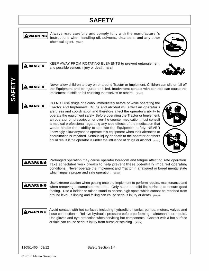
Always read carefully and comply fully with the manufacturer ’sinstructions when handling oil, solvents, cleansers, and any otherchemical agent. (SG-22)
KEEP AWAY FROM ROTATING ELEMENTS to prevent entanglementand possible serious injury or death. (SG-24)
Never allow children to play on or around Tractor or Implement. Children can slip or fall offthe Equipment and be injured or killed. Inadvertent contact with controls can cause theImplement to shift or fall crushing themselves or others. (SG-25)
DO NOT use drugs or alcohol immediately before or while operating theTractor and Implement. Drugs and alcohol will affect an operator’salertness and coordination and therefore affect the operator’s ability tooperate the equipment safely. Before operating the Tractor or Implement,an operator on prescription or over-the-counter medication must consulta medical professional regarding any side effects of the medication thatwould hinder their ability to operate the Equipment safely. NEVERknowingly allow anyone to operate this equipment when their alertness orcoordination is impaired. Serious injury or death to the operator or otherscould result if the operator is under the influence of drugs or alcohol. (SG-27)
Prolonged operation may cause operator boredom and fatigue affecting safe operation.Take scheduled work breaks to help prevent these potentially impaired operatingconditions. Never operate the Implement and Tractor in a fatigued or bored mental statewhich impairs proper and safe operation. (SG-32)
Use extreme caution when getting onto the Implement to perform repairs, maintenance andwhen removing accumulated material. Only stand on solid flat surfaces to ensure goodfooting. Use a ladder or raised stand to access high spots which cannot be reached fromground level. Slipping and falling can cause serious injury or death. (SG-33)
Avoid contact with hot surfaces including hydraulic oil tanks, pumps, motors, valves andhose connections. Relieve hydraulic pressure before performing maintenance or repairs.Use gloves and eye protection when servicing hot components. Contact with a hot surfaceor fluid can cause serious injury from burns or scalding. (SG-34)
1165/1465 03/12 Safety Section 1-4
© 2012 Alamo Group Inc.

SAFETYS
AF
ET
Y
Equipment Operation Safety Instructions and Practices
DO NOT operate this Implement on a Tractor that is not properly maintained. Should amechanical or Tractor control failure occur while operating, immediately shut down theTractor and perform repairs before resuming operation. Serious injury and possible deathcould occur from not maintaining this Implement and Tractor in good operating condition.(SG-36)
Avoid contact with hot surfaces of the engine or muffler. Use gloves and eye protectionwhen servicing hot components. Contact with a hot surface or fluid can cause serious injuryfrom burns or scalding. (SG-38)
Repeated or substantial breathing of hazardous dusts, includingcrystalline silica, could cause fatal or serious respiratory disease includingsilicosis. Concrete, masonry, many types of rock, and various othermaterials contain silica sand. California lists respirable crystalline silica asa substance known to cause cancer. Operation of this equipment undercertain conditions may generate airborne dust particles that could containcrystalline silica. In those conditions, personal protective equipmentincluding an appropriate respirator must be used. If excessive dust isgenerated, a dust collection or suppression system should also be usedduring operation. (SG-41)
Be sure you have adequate knowledge of the property you will be working on. Take time tomake yourself aware of any area underwater or underground lines or cables. Contact withburied lines or cable could result in serious injury or death. (STL-1)
In wet conditions where there is a likelihood of material collecting on the Implement, makecertain that this material is removed before traveling on public roadways. (STL-7)
Keep fingers clear of tongue lock pin holes. A sudden movement could cause injury oreven amputate fingers. KEEP CHILDREN AWAY WHEN CHANGING TONGUEPOSITION. (STL-18)
Operate this Implement only in conditions where you have clear visibility in daylight or withadequate artificial lighting. Never operate in darkness or foggy conditions where youcannot clearly see at least 100 yards in front and to the sides of the tractor and implement.Make sure that you can clearly see and identify passersby, steep slopes, ditches, drop-offs,overhead obstructions, power lines, debris and foreign objects. If you are unable to clearlysee this type of items discontinue operating this equipment.(S3PT-21)
1165/1465 03/12 Safety Section 1-5
© 2012 Alamo Group Inc.

SAFETYS
AF
ET
Y
Operate this Equipment only with a Tractor equipped with an approved roll-over-protective system (ROPS). Always wear seat belts. Serious injury oreven death could result from falling off the tractor--particularly during a turnoverwhen the operator could be pinned under the ROPS. (SG-7)
BEFORE leaving the tractor seat lower the implement, set the parkingbrake and/or set the tractor transmission in parking gear, disengage thePTO, stop the engine, remove the key, and wait for all moving parts tostop. Place the tractor shift lever into a low range or parking gear toprevent the tractor from rolling. Never dismount a Tractor that is movingor while the engine is running. Operate the Tractor controls from thetractor seat only. (SG-9)
Never allow children or other persons to ride on the Tractor or Implement.Falling off can result in serious injury or death. (SG-10)
Never allow children to operate, ride on, or come close to the Tractor orImplement. Usually, 16-17 year-old children who are mature andresponsible can operate the implement with adult supervision, if theyhave read and understand the Operator’s Manuals, been trained inproper operation of the tractor and Implement, and are physically largeenough to reach and operate the controls easily. (SG-11)
Do not mount or dismount the Tractor while the tractor is moving. Mountthe Tractor only when the Tractor and all moving parts are completelystopped. (SG-12)
Start tractor only when properly seated in the Tractor seat. Starting atractor in gear can result in injury or death. Read the Tractor operatorsmanual for proper starting instructions. (SG-13)
1165/1465 03/12 Safety Section 1-6
© 2012 Alamo Group Inc.

SAFETYS
AF
ET
Y
Do not operate this Equipment with hydraulic oil or fuel leaking. Oiland fuel are explosive and their presence could present a hazard. Donot check for leaks with your hand! High-pressure oil streams frombreaks in the line could penetrate the skin and cause tissue damageincluding gangrene. To check for a hose leak, SHUT the unit ENGINEOFF and remove all hydraulic pressure. Wear oil impenetrable gloves,safety glasses and use Cardboard to check for evidence of oil leaks. Ifyou suspect a leak, REMOVE the HOSE and have it tested at a Dealer.If oil does penetrate the skin, have the injury treated immediately by aphysician knowledgeable and skilled in this procedure. (SG-15)
Never run the Tractor engine in a closed building or without adequate ventilation. Theexhaust fumes can be hazardous to your health. (SG-23)
Operate the Tractor and/or Implement controls only while properly seated in the Tractor seatwith the seat belt securely fastened around you. Inadvertent movement of the Tractor orImplement may cause serious injury or death. (SG-29)
In case of mechanical difficulty during operation, place the transmission in the parkposition, set the parking brake, shut down all power, including the PTO and the engine andremove the key. Wait until all rotating motion has stopped before dismounting. (SG-39)
Do Not operate this equipment in areas where insects such as bees may attack you and/orcause you to lose control of the equipment. If you must enter in such areas, use a tractorwith an enclosed Cab and close the windows to prevent insects from entering. If a tractorcab is not available, wear suitable clothing including head, face, and hand protection toshield you from the insects. Attacking insects can cause you to lose control of the tractor,which can result in serious injury or death to you or bystanders. Never dismount a movingtractor. (SG-40)
DO NOT allow any person under a folded wing unless wing is securelylocked up or supported. DO NOT approach the Implement unless theTractor is turned off and all motion has ceased. Never work under theframe work, or any lifted component unless the implement is securelysupported or blocked up. A sudden or inadvertent fall by any of thesecomponents could cause serious injury or even death. (STI-03)
1165/1465 03/12 Safety Section 1-7
© 2012 Alamo Group Inc.
SAFETYS
AF
ET
Y
Connecting or Disconnecting Implement Safety Instructions and Practices
Maintenance and Service Safety Instructions and Practices
Extreme care should be taken when operating near loose objects such as gravel, rocks,wire, and other debris. Inspect the area before tilling. Foreign objects should be removedfrom the site to prevent machine damage and/or bodily injury or even death. Any objects
that cannot be removed must be clearly marked and carefully avoided by the operator. Stop operatingimmediately if blades strike a foreign object. Repair all damage and make certain rotor and blades are ingood condition before resuming operation. (STL-5)
Many varied objects, such as wire, cable, rope, or chains, can become entangled in therotating parts of the Implement. These objects could then swing outside the housing atgreater velocities than the blades. Such a situation is extremely hazardous and couldresult in serious injury or even death. Inspect the area for such objects before working inthe area. Remove any such objects from the site. Never allow the implement to contactsuch objects. (STL-6)
Do not operate the Implement when bystanders or animals are near (within 50 feet) theequipment. This Implement is capable of throwing objects for significant distances andcausing serious injury. Stop the Tractor and Implement immediately if a bystander oranimal comes near the equipment. (STL-13)
Never unhitch without using the Tongue Jack. The Tongue is very heavy. Attempting to liftthe Tongue without using the Tongue Jack could cause strains or other injury. Allowing thetongue to fall suddenly and unexpectedly could result in crushing injury. Use the TongueJack for lifting the Implement only. Overloading the Tongue Jack can cause failure withpossible serious bodily injury or even death. (STI-04)
Always disconnect the main PTO Driveline from the Tractor before performing service onthe Implement. Never work on the Implement with the tractor PTO driveline connected andrunning. Rotating Parts, Blades or Drivelines could turn without warning and causeimmediate entanglement, injury or death. (S3PT-11)
Always maintain the safety signs in good readable condition. If the safety signs are missing,damaged, or unreadable, obtain and install replacement safety signs immediately. (SG-5)
Do not modify or alter this Implement. Do not permit anyone to modify or alter thisImplement, any of its components or any Implement function. (SG-8)
1165/1465 03/12 Safety Section 1-8
© 2012 Alamo Group Inc.

SAFETYS
AF
ET
Y
Ensure any remote starting system is inoperative before servicing or cleaning the machine. Inadvertent engine start up could result in entanglement or runover causing serious injuries
or death. (SSB-17)
Never work under the Implement, the framework, or any liftedcomponent unless the Implement is securely supported or blocked upto prevent sudden or inadvertent falling which could cause seriousinjury or even death. (SG-14)
Never attempt to lubricate, adjust, or remove material from the Implement while it is inmotion or while tractor engine is running. (SG-20)
Periodically inspect all moving parts for wear and replace whennecessary with authorized service parts. Look for loose fasteners, wornor broken parts, and leaky or loose fittings. Make sure all pins havecotter pins and washers. Serious injury may occur from not maintainingthis machine in good working order. (SG-21)
Perform service, repairs and lubrication according to the maintenance section. Ensure theunit is properly lubricated as specified in the lubrication schedule and all bolts and nuts areproperly torqued. Failure to properly service, repair and maintain this Implement in goodoperating condition could cause component failure and possible serious injury or evendeath. (SG-35)
Use caution and wear protective gloves when handling sharp objects such as blades,knives, and other cutting edges. Be alert to worn component surfaces which have sharpedges. Sharp surfaces can inflict severe laceration injuries if proper hand protection is notworn. (SG-37)
PARTS INFORMATION
EarthMaster implements use matched system components for blades, hangers, rollers, and bearings. Theseparts are made and tested to EarthMaster specifications. Non-genuine "will fit" parts do not consistently meetthese specifications. The use of “will fit” parts may reduce the implements performance, void warranties, andpresent a safety hazard. Use genuine EarthMaster parts for economy and safety. (SPEM-1)
SEE YOUR EARTHMASTER DEALER
1165/1465 03/12 Safety Section 1-9
© 2012 Alamo Group Inc.
SAFETYS
AF
ET
Y
Use extreme care when climbing onto the Equipment to perform repairs, maintenance, and
cleaning. Use proper stands and ladders to access areas that cannot be reached from
ground level. Slipping and falling off the Equipment can cause serious injury or death. (SSB-
25)
Transporting Safety Instructions and Practices
Exercise care when handling the discs. Disc blades are SHARP and HEAVY. Wear glovesat all time to protect your hands. (STL-10)
Do not use your hands or feet to clean the disc gangs. The discs are sharp and seriousinjures could result from inadvertent contact with the discs. Never attempt to stand on thediscs, tires, or frame members of the implement. (STL-11)
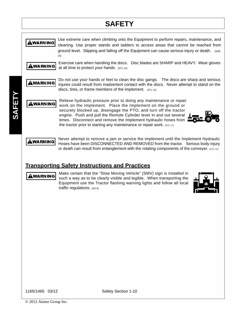
Relieve hydraulic pressure prior to doing any maintenance or repairwork on the Implement. Place the Implement on the ground orsecurely blocked up, disengage the PTO, and turn off the tractorengine. Push and pull the Remote Cylinder lever in and out severaltimes. Disconnect and remove the Implement hydraulic hoses fromthe tractor prior to starting any maintenance or repair work. (STL-17)
Never attempt to remove a jam or service the implement until the Implement HydraulicHoses have been DISCONNECTED AND REMOVED from the tractor. Serious body injuryor death can result from entanglement with the rotating components of the conveyer. (STL-25)
Make certain that the “Slow Moving Vehicle” (SMV) sign is installed insuch a way as to be clearly visible and legible. When transporting theEquipment use the Tractor flashing warning lights and follow all localtraffic regulations. (SG-6)
1165/1465 03/12 Safety Section 1-10
© 2012 Alamo Group Inc.

SAFETYS
AF
ET
Y
Transport only at speeds where you can maintain control of theequipment. Serious accidents and injuries can result from operating thisequipment at high speeds. Understand the Tractor and Implement and
how it handles before transporting on streets and highways. Make sure the Tractor steeringand brakes are in good condition and operate properly.
Before transporting the Tractor and Implement, determine the proper transport speeds foryou and the equipment. Make sure you abide by the following rules:
Test the tractor at a slow speed and increase the speed slowly. Apply the Brakes smoothlyto determine the stopping characteristics of the Tractor and Implement. As you increasethe speed of the Tractor the stopping distance increases. Determine the maximumtransport speed not to exceed 20 mph (30 kph) for transporting this equipment.
Test the equipment at a slow speed in turns. Increase the speed through the turn only afteryou determine that the equipment can be operated at a higher speed. Use extreme careand reduce your speed when turning sharply to prevent the tractor and implement fromturning over. Determine the maximum turning speed for you and this equipment beforeoperating on roads or uneven ground.
Only transport the Tractor and Implement at the speeds which allow you to properly controlthe equipment.
Be aware of the operating conditions. Do not operate the Tractor with weak or faulty brakesor worn tires. When operating down a hill or on wet or rain slick roads, the braking distanceincreases: use extreme care and reduce your speed. When operating in traffic always usethe Tractor’s flashing warning lights and reduce your speed. Be aware of traffic around youand watch out for the other guy. (SG-19)
Be particularly careful when transporting the Implement using the tractor. Turn curves orgo up or down hills only at a low speed and at a gradual steering angle. Make certain thatat least 20% of the tractor’s weight is on the front wheels to maintain safe steerage. Slowdown on rough or uneven surfaces. (STI-01)
Only tow the Implement behind a properly sized and equipped Tractorwhich exceeds the weight of the Implement by at least 20%. DO NOTtow the Implement behind a truck or other type of vehicle. Never tow theImplement and another Implement connected in tandem. Never tow theImplement at speeds over 20 MPH. (STI-06)
Secure the Implement for transport before traveling on public roads. For pull-typeImplements, secure the center axle using cylinder stops or transport pin and properly attacha safety chain between the Implement and Tractor. Secure wings in upright position onfolding Implements using wing transport locks. (STI-7)
1165/1465 03/12 Safety Section 1-11
© 2012 Alamo Group Inc.
SAFETYS
AF
ET
Y
Concluding Safety Instructions and Practices
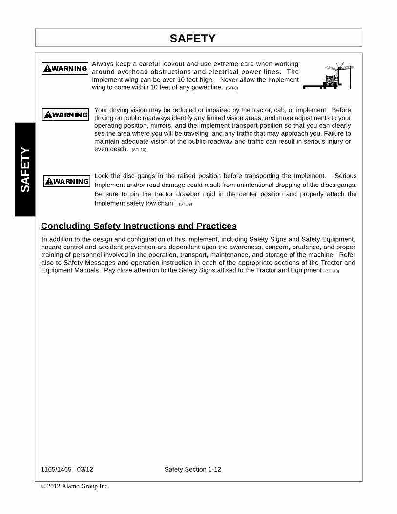
Always keep a careful lookout and use extreme care when workingaround overhead obstructions and electrical power lines. TheImplement wing can be over 10 feet high. Never allow the Implementwing to come within 10 feet of any power line. (STI-8)
Your driving vision may be reduced or impaired by the tractor, cab, or implement. Beforedriving on public roadways identify any limited vision areas, and make adjustments to youroperating position, mirrors, and the implement transport position so that you can clearlysee the area where you will be traveling, and any traffic that may approach you. Failure tomaintain adequate vision of the public roadway and traffic can result in serious injury oreven death. (STI-10)
Lock the disc gangs in the raised position before transporting the Implement. Serious
Implement and/or road damage could result from unintentional dropping of the discs gangs.
Be sure to pin the tractor drawbar rigid in the center position and properly attach the
Implement safety tow chain. (STL-9)
In addition to the design and configuration of this Implement, including Safety Signs and Safety Equipment,hazard control and accident prevention are dependent upon the awareness, concern, prudence, and propertraining of personnel involved in the operation, transport, maintenance, and storage of the machine. Referalso to Safety Messages and operation instruction in each of the appropriate sections of the Tractor andEquipment Manuals. Pay close attention to the Safety Signs affixed to the Tractor and Equipment. (SG-18)
1165/1465 03/12 Safety Section 1-12
© 2012 Alamo Group Inc.

SAFETYS
AF
ET
Y
Decal LocationNote: EarthMaster supplies safety decals on this product to promote safe operation. Damage to the decalsmay occur while in shipping, use or reconditioning. EarthMaster cares about the safety of its customers,operators, and bystanders, and will replace the safety decals on this product in the field, free of charge (Someshipping and handling charges may apply). Contact EarthMaster dealer to order replacement decals.
1165/1465 03/12 Safety Section 1-13
© 2012 Alamo Group Inc.

SAFETYS
AF
ET
Y
IITEM PART NO. QTY TYPE DESCRIPTION
1. D742 1 IMPORTANT Read Operators Manual2. 00771039 1 IMPORTANT Use EarthMaster Genuine Parts3. D605 1 WARNING Jack Stand Load4. D743 1 IMPORTANT Attach Safety Chain5. D604 1 DANGER Multi-Hazard6. D594 1 WARNING Multi-Hazards7. 00725746 1 PELIGRO Spanish - Get Translation8. 1458380 1 INFO Made in USA9. 2468310 1 INSTRUCT Lubrication Chart10. 00763977 1 IMPORTANT Notice to Owner11. 2468317 1 INFO Ripper Depth Setting12. 02962765 2 DANGER Crushing and Pinch Points13. 2468308 3 INSTRUCT Maintenance14. 2468309 3 WARNING Possible Crushing (Not Shown in Description)15. 02962764 20 WARNING Pinch Points16. 3668308 1 WARNING Transport17. 2438339 2 NAME Model 1165
2438340 1 NAME Model 146518. 4038309 2 LOGO EarthMaster19. 00776031 1 _________ Canister, Operator’s Manual20. 5004WC 1 _________ Operator’s Manual21. 10058000 3 _________ Bolt22. 00024100 3 _________ Flatwasher23. 02959924 3 _________ Locknut24. 03200347 * REFLECT SMV Sign25. 1458398 4 REFLCTR Orange Reflector (Not Shown)26. 1458393 8 REFLCTR Yellow Reflector27. 1458392 4 REFLCTR Red Reflector(Not Shown)
Note: EarthMaster supplies safety decals on this product to promote safe operation. Damage to the decalsmay occur while in shipping, use or reconditioning. EarthMaster cares about the safety of its customers,operators, and bystanders, and will replace the safety decals on this product in the field, free of charge (Someshipping and handling charges may apply). Contact EarthMaster dealer to order replacement decals.
1165/1465 03/12 Safety Section 1-14
© 2012 Alamo Group Inc.

SAFETYS
AF
ET
Y
Decals
1165/1465 03/12 Safety Section 1-15
© 2012 Alamo Group Inc.

SAFETYS
AF
ET
Y
1165/1465 03/12 Safety Section 1-16
© 2012 Alamo Group Inc.

SAFETYS
AF
ET
Y
1165/1465 03/12 Safety Section 1-17
© 2012 Alamo Group Inc.

SAFETYS
AF
ET
Y
1165/1465 03/12 Safety Section 1-18
© 2012 Alamo Group Inc.

SAFETYS
AF
ET
Y
1165/1465 03/12 Safety Section 1-19
© 2012 Alamo Group Inc.
SAFETYS
AF
ET
Y
Federal Laws and Regulations
This section is intended to explain in broad terms the concept and effect of federal laws and regulations concerningemployer and employee equipment operators. This section is not intended as a legal interpretation of the law andshould not be considered as such.
Employer-Employee Operator Regulations
U.S. Public Law 91-596 (The Williams-Steiger Occupational and Health Act of 1970) OSHA
This Act Seeks:
“...to assure so far as possible every working man and woman in the nation safe and healthful workingconditions and to preserve our human resources...”
DUTIESSec. 5 (a) Each employer-
(1) shall furnish to each of his employees employment and a place of employment which are free fromrecognized hazards that are causing or are likely to cause death or serious physical harm to his employees;
(2) shall comply with occupational safety and health standards promulgated under this Act.
(b) Each employee shall comply with occupational safety and health standards and all rules, regulations andorders issued pursuant to this Act which are applicable to his own actions and conduct.
OSHA Training Requirements
Title 29, Code of Federal Regulations Part 1928.57(a)(6). www.osha.gov
Operator instructions. At the time of initial assignment and at least annually thereafter, the employer shallinstruct every employee who operates an agricultural tractor and implements in the safe operating practicesand servicing of equipment with which they are or will be involved, and of any other practices dictated by thework environment.
Keep all guards in place when the machine is in operation;
Permit no riders on equipment
Stop engine, disconnect the power source, and wait for all machine movement to stop before servicing,adjusting, cleaning or unclogging the equipment, except where the machine must be running to be properlyserviced or maintained, in which case the employer shall instruct employees as to all steps and procedureswhich are necessary to safely service or maintain the equipment.
Make sure everyone is clear of machinery before starting the engine, engaging power, or operating themachine.
Employer Responsibilities:
To ensure employee safety during Tractor and Implement operation, it is the employer’s responsibility to:
1. Train the employee in the proper and safe operation of the Tractor and Implement.
2. Require that the employee read and fully understand the Tractor and Implement Operator’s manual.
3. Permit only qualified and properly trained employees to operate the Tractor and Implement.
4. Maintain the Tractor and Implement in a safe operational condition and maintain all shields and guards on theequipment.
5. Ensure the Tractor is equipped with a functional ROPS and seat belt and require that the employee operatorsecurely fasten the safety belt and operate with the ROPS in the raised position at all times.
6. Forbid the employee operator to carry additional riders on the Tractor or Implement.
7. Provide the required tools to maintain the Tractor and Implement in a good safe working condition and provide thenecessary support devices to secure the equipment safely while performing repairs and service.
8. Require that the employee operator stop operation if bystanders or passersby come within 300 feet.
Child Labor Under 16 Years of Age
Some regulations specify that no one under the age of 16 may operate power machinery. It is your responsibility toknow what these regulations are in your own area or situation. (Refer to U.S. Dept. of Labor, Employment StandardAdministration, Wage & Home Division, Child Labor Bulletin #102.)
1165/1465 03/12 Safety Section 1-20
© 2012 Alamo Group Inc.

Introduction Section 2-1
INTRODUCTION SECTION
INTRODUCTIONIN
TR
OD
UC
TIO
N
These tillers are designed with care and built with quality materials by skilled workers. Proper assembly,maintenance, and operating practices, as described in this manual, will help the owner/operator get years ofsatisfactory service from the machine.
The purpose of this manual is to familiarize, instruct, and train. The Assembly Section instructs the owner/operator in the correct assembly of the Implement using standard and optional equipment. The Parts Listingsection is designed to familiarize the owner/operator with replaceable parts on the Implement. This sectionprovides exploded assembly drawings of each mower component illustrating each piece and thecorresponding part number.
Careful use and timely service save extensive repairs and costly downtime losses. The Operation andMaintenance Sections of the manual train the owner/operator how to work the Implement correctly and attendto appropriate maintenance. The Trouble Shooting Guide helps diagnose difficulties with implement and offerssolution to the problems.
Safety is of primary importance to the owner/operator and to the manufacturer. The first section of this manualincludes a list of Safety Messages, that, if followed, will help protect the operator and bystanders from injury ordeath. Many of the Safety Messages will be repeated throughout the manual. The owner/operator/dealershould know these Safety Messages before assembly and be aware of the hazards of operating thisimplement during assembly, use, and maintenance. The Safety Alert Symbol combined with a Signal Word, asseen below, is intended to warn the owner/operator of impending hazards and the degree of possible injuryfaced when operating this machine.
Indicates an imminently hazardous situation that, if not avoided, WILL result in DEATH ORVERY SERIOUS INJURY.
Indicates an imminently hazardous situation that, if not avoided, COULD result in DEATHOR SERIOUS INJURY.
Indicates an imminently hazardous situation that, if not avoided, MAY result in MINORINJURY.
Identifies special instructions or procedures that, if not strictly observed, could result indamage to, or destruction of the machine, attachments or the environment.
The new Earthmaster is designed with two tillage tools, a tandem disc and a V-chisel connected together asone unit for one pass operation even in standing corn stalks. Also, the two tools can be separated from eachother to be used as a tandem disc only or a 3-point hitch mounted V-Chisel plow.
The heavy-duty tandem disc is designed to chop the residue and penetrate the soil up to 5” deep to incorporatethe crop residue with the top layer of soil. The depth of cutting and the angle of the disc gangs can be adjustedfor the desired amount of crop residue incorporated to protect the soil against wind and water erosion.
The V-Chisel bar design places the chisel shanks behind each other to allow crop residue to flow between andaround them. The 36” tall parabolic design chisel shank will penetrate the soil up to 15” deep to get under thehard plow sole - lifting, shattering and breaking it up with the least amount of power required. This allows thesurface water to penetrate the soil fast which allows your fertilizer to penetrate deeper into the soil, but most ofall it allows your crop roots to penetrate deeper into the soil to use the valuable moisture and fertilizer allseason long and even during a dry season.
1165/1465 03/12 Introduction Section 2-2
© 2012 Alamo Group Inc.

INTRODUCTIONIN
TR
OD
UC
TIO
N
Attention Owner/Operator
BEFORE OPERATING THIS MACHINE:
1. Carefully read the Operator’s Manual, completely understand the Safety Messages and instructions, andknow how to operate correctly both the tractor and implement.
2. Fill out the Warranty Card in full. Be sure to answer all questions, including the Serial Number of theImplement. Mail within 30 days of delivery date of this implement.
NOTE: Warranties are honored only if completed “Owner Registration and Warranty” forms are received byAlamo Group within thirty days of delivery of the implement.
3. Record the Implement Model and Serial Numbers on the Warranty page at the front of the Operator’sManual. Keep this as part of the permanent maintenance file for the Implement.
1165/1465 03/12 Introduction Section 2-3
© 2012 Alamo Group Inc.


Assembly Section 3-1
ASSEMBLY SECTION

ASSEMBLYA
SS
EM
BLY
TRACTOR PREPARATIONHave a tractor with sufficient horsepower and traction. Soil type, soil moisture, type of crop, depth of opera-tion,etc. will determine horsepower and traction requirements. Normally, 25 to 35 horsepower per shank isre-quired. Have your tractor adequately equipped to operate at speeds of 4-1/2 MPH to 6 MPH as this speedwillprovide the best results.
All personnel should wear hard hats, safety shoes, safety glasses, and proper hearing pro-tection at all times during the assembly process for protection from injury.
The components of this implement are very heavy. Securely lift the components usingappropriate and adequate lifting devices. Block all components up securely before workingor reaching under components.
Use extreme caution when getting onto the Implement to perform assembly procedures ormaintenance. Only stand on solid flat surfaces to ensure good footing. Use a ladder orraised stand to access high spots which cannot be reached from ground level. Slipping andfalling can cause serious injury or death.
Use genuine M&W parts and fasteners. These parts are made and tested to M&W specifica-tions. Non-genuine “will fit” parts do not consistently meet these specifications. The use of“will fit” parts may reduce the implements performance, void warranties, and present asafety hazard.
READ, UNDERSTAND, and FOLLOW the following Safety Messages. Serious injury ordeath may occur unless care is taken to follow the warnings and instructions stated in theSafety Messages. Always use good common sense to avoid hazards. (SG-2)
Always read carefully and comply fully with the manufacturer’s instruc-tions when handling oil, solvents, cleansers, and any other chemicalagent. (SG-22)
Never work under the Implement, the framework, or any lifted compo-nent unless the Implement is securely supported or blocked up to pre-vent sudden or inadvertent falling which could cause serious injury oreven death. (SG-14)
Use caution and wear protective gloves when handling sharp objects such as blades,knives, and other cutting edges. Be alert to worn component surfaces which have sharpedges. Sharp surfaces can inflict severe laceration injuries if proper hand protection is notworn. (SG-37)
1165/1465 03/12 Assembly Section 3-2
© 2012 Alamo Group Inc.

ASSEMBLYA
SS
EM
BLY
CONNECTING CHISEL BAR TO DISC1. Connect the toggle hitch bars of the disc unit in
the top holes of the outer hitch plates of thechisel bar.
2. Connect the adjusting screw link in the top holeof the center hitch plates of the chisel bar.
DISC DEPTH SETTING
1. Set the disc depth by removing the depthcontrol pins or by placing them in on thefollowing holes.
NOTE: There is one pin on each side. Both pinsmust be placed in the same hole location on bothsides.
PIN LOCATION DISC DEPTHHole No. 0”Hole No. 2 1”Hole No. 3 2”Hole No. 4 3”Hole No. 5 4”Pin Removed 5”
Note: All depths are approximate because of variations in tire compaction in different soils.
1165/1465 03/12 Assembly Section 3-3
© 2012 Alamo Group Inc.

ASSEMBLYA
SS
EM
BLY
CHISEL DEPTH SETTING1. Set the chisel depth by installing the stop pins
(one on each side of toggle hitch bar) in one ofthe following hole locations
Note: Hitch bar on both sides must be set at thesame position.
HOLE NO. CHISEL DEPTH 1 9” 2 10-1/2” 3 12” 4 13-1/2” 5 15”
Note: All dimensions are based on a disc setting of 5” depth. All dimensions are approximate because ofvariations in tire compaction in different soils.
2. To change the chisel bar to a deeper depth:-Lower the Earthmaster all the way with the chisel points setting on top of the ground. This will free the bottompins. Remove then and install then in a lower hole. Align the pin so the toggle hitch bar will rest on the pin’s flatsurface.
3. To change the chisel bar to a shallower depth:-Raise the Earthmaster all the way with the chisel points off the ground. This will free the top pins. Removethem and install then in a lower hole. Align the pin so the toggle hitch bar will rest on the pin’s flat surface.
-Lower the Earthmaster all the way with the chisel points setting on top of the ground. This will place the togglehitch bars resting on the top pins. Remove the bottom pins and install them in the hole at the bottom of thetoggle hitch bar.
DISC FRAME SET-UPThe Eathmaster may be partially assembledwhen recieved. If so it will be necessary tocomplete all steps shown in this manual. Performonly the steps necessary to complete assembly.
1. Install the wheel strut axel to the disc framepositioning the stop tubes of the wheel axleon the top side, using (2) 1-1/4” x 6-1/8” longpins, slotted nuts and 1/4” x 2” cotter pins.Position head of pin against the stop blockto keep pin from rotating and just tighten nutsnug. Grease the (2) fittings at these pins.Install the tire and wheel assemblies to thehubs.
1165/1465 03/12 Assembly Section 3-4
© 2012 Alamo Group Inc.

ASSEMBLYA
SS
EM
BLY
2. Install the (2) 1-5/8” OD x 1-1/4” ID hardbushings in the cylinder mount holes,postioning them with the split part of thebushing to the top side of a straight linebetween the two holes.
3. Install (1) 1/4” x 2” roll pin in each of the (2)1” diameter x 7” long stop pins. Install these(2) pins to the disc frame (one on each side)positioning them on the same hole location.Install (1) 1/4” klick pin
4. Install the (2) toggle hitch bars to the discframe (one on each side) using (1) 1-1/8”diameter x 3-9/16” long pin and (2) 1/4” x 1-3/4” cotter pins. Install (1) 1/4” x 2” roll pin ineach of the (4) 1-1/8” x 5 long stops pins.Install the stop pins to the disc frame (two oneach side), (1) on the top side and (1) on thebottom side of the toggle hitch bar,postioning them at the same hole location oneach side of the disc frame. Install (1) 1/4”klick pin in each of the stop pins.
1165/1465 03/12 Assembly Section 3-5
© 2012 Alamo Group Inc.

ASSEMBLYA
SS
EM
BLY
5. Install the screw link to the disc frame using(1) 1-1/8” diameter x 4” long pin and (2) 1/4”x 1-3/4” cotter pins. Install the handle rod inthe screw link. Install a 1/4” klick pin in thehole in the handle rod.
6. Install the tongue to the disc frame with thejack mount on left-hand side as shown using(2) 1-1/8” diameter x 4” long pins and (4) 5/16” x 2-1/2” roll pins. Install with 1/4”extending from top of pin and the remainderof the 5/16” roll pin estending into the hole toprevent the pin from rotating. Install the hitchclevis to the tongue using (1) 1-1/4” diameterx 8-1/8” long pin, 1 1/4-7 slotted nut and 1/4”x 2 cotter pin.
7. Install the transport lock tube on the tonguecylinder. Install the lock pin through the holein the tongue cylinder. Install a 1/4” klick pinin the hole in end of lock pin.
1165/1465 03/12 Assembly Section 3-6
© 2012 Alamo Group Inc.
ASSEMBLYA
SS
EM
BLY
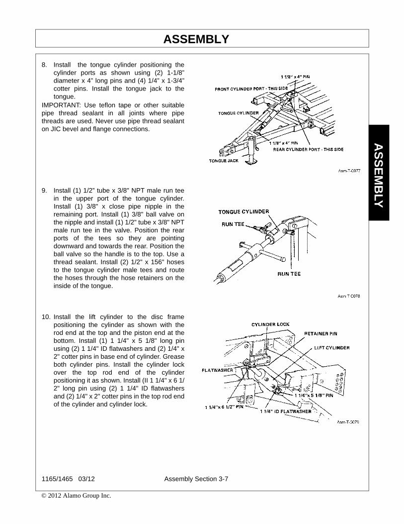
8. Install the tongue cylinder positioning thecylinder ports as shown using (2) 1-1/8”diameter x 4” long pins and (4) 1/4” x 1-3/4”cotter pins. Install the tongue jack to thetongue.
IMPORTANT: Use teflon tape or other suitablepipe thread sealant in all joints where pipethreads are used. Never use pipe thread sealanton JIC bevel and flange connections.
9. Install (1) 1/2” tube x 3/8" NPT male run teein the upper port of the tongue cylinder.Install (1) 3/8" x close pipe nipple in theremaining port. Install (1) 3/8" ball valve onthe nipple and install (1) 1/2" tube x 3/8" NPTmale run tee in the valve. Position the rearports of the tees so they are pointingdownward and towards the rear. Position theball valve so the handle is to the top. Use athread sealant. Install (2) 1/2" x 156" hosesto the tongue cylinder male tees and routethe hoses through the hose retainers on theinside of the tongue.
10. Install the lift cylinder to the disc framepositioning the cylinder as shown with therod end at the top and the piston end at thebottom. Install (1) 1 1/4" x 5 1/8" long pinusing (2) 1 1/4" ID flatwashers and (2) 1/4" x2" cotter pins in base end of cylinder. Greaseboth cylinder pins. Install the cylinder lockover the top rod end of the cylinderpositioning it as shown. Install (II 1 1/4" x 6 1/2" long pin using (2) 1 1/4" ID flatwashersand (2) 1/4" x 2" cotter pins in the top rod endof the cylinder and cylinder lock.
1165/1465 03/12 Assembly Section 3-7
© 2012 Alamo Group Inc.
ASSEMBLYA
SS
EM
BLY
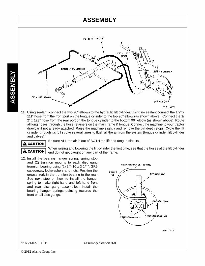
11. Using sealant, connect the two 90° elbows to the hydraulic lift cylinder. Using no sealant connect the 1/2" x111" hose from the front port on the tongue cylinder to the top 90° elbow (as shown above). Connect the 1/2" x 123" hose from the rear port on the tongue cylinder to the bottom 90° elbow (as shown above). Routeall long hoses through the hose retainers on the main frame & tongue. Connect the machine to your tractordrawbar if not already attached. Raise the machine slightly and remove the pin depth stops. Cycle the liftcylinder through it's full stroke several times to flush all the air from the system (tongue cylinder, lift cylinderand valves).
Be sure ALL the air is out of BOTH the lift and tongue circuits.
When raising and lowering the lift cylinder the first time, see that the hoses at the lift cylinderend do not get caught on any part of the frame.
12. Install the bearing hanger spring, spring stopand (2) trunnion mounts to each disc gangtrunnion bearing using (2) 3/4-10 x 3 1/4", GR5capscrews, lockwashers and nuts. Position thegrease zerk in the trunnion bearing to the rear.See next step on how to install the hangerspring to make right-hand and left-hand frontand rear disc gang assemblies. Install thebearing hanger springs pointing towards thefront on all disc gangs.
1165/1465 03/12 Assembly Section 3-8
© 2012 Alamo Group Inc.
ASSEMBLYA
SS
EM
BLY
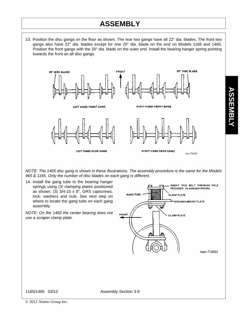
13. Position the disc gangs on the floor as shown. The rear two gangs have all 22" dia. blades. The front twogangs also have 22" dia. blades except for one 20" dia. blade on the end on Models 1166 and 1465.Position the front gangs with the 20" dia. blade on the outer end. Install the bearing hanger spring pointingtowards the front an all disc gangs.
NOTE: The 1465 disc gang is shown in these illustrations. The assembly procedure is the same for the Models965 & 1165. Only the number of disc blades on each gang is different.
14. Install the gang tube to the bearing hangersprings using (3! clamping plates positionedas shown, (3) 3/4-10 x 8", GRS capscrews,lock- washers and nuts. See next step onwhere to locate the gang tube on each gangassembly.
NOTE: On the 1465 the center bearing does notuse a scraper clamp plate.
1165/1465 03/12 Assembly Section 3-9
© 2012 Alamo Group Inc.

ASSEMBLYA
SS
EM
BLY
15. The front and rear gang tubes ira different lengths. The front tubes are shorter than the rear tubes. (1465tubes are shown here. The length of the tube is different on the 965 & 1165 and only two hangers are usedon each gang.) Position the gang tubes with the mounting plate on the top side. Position the front tubes 61/2" and the rear tubes 12 1/2" from center of mounting hole to the edge of the inside clamp plate. Looselysecure the hanger spring to the bottom of the gang tube with the bolts.
Tighten the bolts on the inside hanger spring first. (One elosest to the gang tube mounting hole.) Then, tightenthe bolts on the outer hanger springs, making sure the top of the hanger springs are flat with the bottom of thegang tube.
If the hanger springs do not fit flat when tightening the clamp bolts, the hanger springs willcreate a side load that will push or pull on it's bearing and the other bearings which willresult in early bearing failure, which will not be covered by warranty.
1165/1465 03/12 Assembly Section 3-10
© 2012 Alamo Group Inc.

ASSEMBLYA
SS
EM
BLY
16. Install the gangs under the disc frame using (1) 1" x 3" GR5 capserew, lockwasher and nut in the insidemounting hole. Position the gang at the center angle position and secure with the clamp plate, (2) 1" x 7"GR5 capscrews, lockwashers and nuts.
17. (4) U-bolts and (8) 3/4" nuts have been supplied for support while positioning disc gangs to the desiredangle. Locate the U-bolts against the bot-tom of the gang tube allowing 1/16" between the bottom of thegang tube, and support surface of the U-bolt. Tighten 3/4" nuts as shown in illus-tration. This 1/16" willallow you to loosen your png clamp plate, and reposition the disc gang without removal of gang.
1165/1465 03/12 Assembly Section 3-11
© 2012 Alamo Group Inc.

ASSEMBLYA
SS
EM
BLY
When removing the bolts securing the disc gangs to the outer frame rails, the gang must notbe allowed to drop down. Failure to support the gang with the supplied U-bolts will result in abent center bolt) Before removing the bolts securing the gang, make sure the U-bolts are setwith the required 1/16" space to allow movement of disc gang. If U-bolts are set to low,center bolt damage will occur. After desired angle has been set, reinstall bolts and clampplate.Tighten all fasteners before operation.
18. The Earthmaster may be equipped withmanual or automatic chisel shankassemblies. The Model 965 uses (1) centershank assembly and (1) each of right handand left hand assemblies or (2) right handassemblies and (2) left hand assemblies.The Model 1165 uses (1! center shankassembly and {2} right and left handassemblies. The Model 14SS uses (1) centershank assembly and (3) right and left handassemblies. Install the chisel shankassemblies on the chisel bar so they are 24"apart as shown. Do not measure parallel tothe bar, measure the distance at a rightangle to the shanks. Install the center shankon the holes provided in the canter tubeusing (4) 3/4" x 6" GR5 cap- screws,lockwashers and nuts.
1165/1465 03/12 Assembly Section 3-12
© 2012 Alamo Group Inc.

ASSEMBLYA
SS
EM
BLY
19. Install the hitch pins in the chisel bar as shown. Install a 1/4” x 2” roll pin in the 1/4” dia. hole and 1/4” klickpin in the 9/32” dia. hole in each hitch pin. See instruction manual for connecting chisel bar to the disc unitor the tractor 3-point hitch.
1165/1465 03/12 Assembly Section 3-13
© 2012 Alamo Group Inc.

Safety Reflector Attachment

Operation Section 4-1
OPERATION SECTION

OPERATIONO
PE
RA
TIO
N
EARTHMASTER 1165-1465OPERATION INSTRUCTIONS
The tillage implement is manufactured with quality material by skilled workers. This implement is ideal inhorticultural, agricultural, or commercial applications, especially for landscapers, rental yards, vineyards,vegetable farms, and nurseries. The implement is equipped with protective deflectors to prevent objects beingthrown from the implement by the blades, however, no shielding is 100% effective. All shields, guards, anddeflectors equipped on the unit must be maintained on the implement in good operational condition.
It is the operator’s responsibility to be knowledgeable of all potential operating hazards and to take everyreasonable precaution to ensure oneself, others, animals, and property are not injured or damaged by theimplement, tractor, or a thrown object. Do not operate the implement if passersby, pets, livestock, or propertyare directly in front or to the rear of the unit.
This section of the Operator’s Manual is designed to familiarize, instruct, and educate safe and properimplement use to the operator. Pictures contained in this section are intended to be used as a visual aid toassist in explaining the operation of a tillage implement. Some pictures may show shields removed forpurposes of clarity. NEVER OPERATE this implement without all shields in place and in good operationalcondition. The operator must be familiar with the implement and tractor operation and all associated safetypractices before operating the implement and tractor. Proper operation of implement, as detailed in thismanual, will help ensure years of safe and satisfactory use of the implement.
IMPORTANT: To avoid implement damage, retorque all bolts after the first 10 hours of operation. Refer to theTorque Chart at the end of the Maintenance Section to ensure bolts are properly tightened.
READ AND UNDERSTAND THE ENTIRE OPERATING INSTRUCTIONS AND SAFETY SECTION OF THISMANUAL AND THE TRACTOR MANUAL BEFORE ATTEMPTING TO USE THE TRACTOR ANDIMPLEMENT. If you do not understand any of the instructions, contact your nearest authorized dealer for afull explanation. Pay close attention to all safety signs and safety messages contained in this manual andthose affixed to the implement and tractor. OPS-U- 0001
READ, UNDERSTAND, and FOLLOW the following Safety Messages. Serious injury ordeath may occur unless care is taken to follow the warnings and instructions stated in theSafety Messages. Always use good common sense to avoid hazards. (SG-2)
Operation Section 4-2
© 2012 Alamo Group Inc.

OPERATIONO
PE
RA
TIO
N
1. Standard Equipment and Specifications
1165 1465
Disc Cutting Width (Max.) 11’1” 13’5”
Transport Width (Max.) 12”2”‘ 14’7”
Total Length 23 23
Height 5’8’
Lift Travel 24” 24”
Ground Clearance (Raised) 12” 12’
Disc Gang Bearings 4 Double-Tapered Roller 6 Double-Tapered Roller
Furrow Filler Blades N/A 2 Std.
Disc Blade Spacing 15” 15”
Shank Spacing Max. 7 on 24” Max. 7 on 24”
Wheels (2) 8” x 15” (2) 8” x 15”
Tires (2) 10-15, 8 Ply (2) 10-15, 8 Ply
Weight 5813 lbs. 7051 lbs.
*Ratings based on actual field performance.
Operating this implement in an application for which it is not designed and/or operating theimplement with the wrong size Tractor can cause implement component damage andequipment failure resulting in possible serious injury or death.
1165/1465 3/12 Operation Section 4-3
© 2012 Alamo Group Inc.

OPERATIONO
PE
RA
TIO
N
2. OPERATOR REQUIREMENTSSafe operation of the unit is the responsibility of a qualified operator. A qualified operator has read andunderstands the implement and tractor Operator’s Manuals and is experienced in implement and tractoroperation and all associated safety practices. In addition to the safety messages contained in this manual,safety signs are affixed to the implement and tractor. If any part of the operation and safe use of thisequipment is not completely understood, consult an authorized dealer for a complete explanation.
If the operator cannot read the manuals for themselves or does not completely understand the operation of theequipment, it is the responsibility of the supervisor to read and explain the manuals, safety practices, andoperating instructions to the operator.
Safe operation of equipment requires that the operator wear approved Personal Protective Equipment (PPE)for the job conditions when attaching, operating, servicing, and repairing the equipment. PPE is designed toprovide operator protection and includes the following safety wear:
PERSONAL PROTECTIVE EQUIPMENT (PPE)
• Always Wear Safety Glasses• Hard Hat• Steel Toe Safety Footwear• Gloves• Hearing Protection• Close Fitting Clothing• Respirator or Filter Mask (depends on
operating conditions) OPS-U- 0002
DO NOT use drugs or alcohol immediately before or while operating theTractor and Implement. Drugs and alcohol will affect an operator’salertness and coordination and therefore affect the operator’s ability tooperate the equipment safely. Before operating the Tractor or Implement,an operator on prescription or over-the-counter medication must consulta medical professional regarding any side effects of the medication thatwould hinder their ability to operate the Equipment safely. NEVERknowingly allow anyone to operate this equipment when their alertness orcoordination is impaired. Serious injury or death to the operator or otherscould result if the operator is under the influence of drugs or alcohol. (SG-27)
Operation Section 4-4
© 2012 Alamo Group Inc.

OPERATIONO
PE
RA
TIO
N
3. TRACTOR REQUIREMENTS
The tractor used to operate the implement must have the power capacity to lift, pull, and operate the PowerTake Off (PTO) at the implement’s rated speed while traveling at a ground speed between 4-1/2 to 6 MPH.Operating the implement with a tractor that does not meet the following requirements may cause tractor orimplement damage and be a potential danger to the operator and passersby.
Tractor Requirements and Capabilities• ASABE approved Roll-Over Protective Structure (ROPS) or ROPS cab and seat belt.• Slow Moving Vehicle (SMV) emblem, lighting, PTO master shield• Tractor Horsepower....................................... 25 HP• Hitch- Lifting Capacity ................................... 1165 - 5813 lbs., 1465 - 7051 lbs.• Hitch .............................................................. 3-Point, CAT II and CAT III• Front End Weight .......................................... As needed to maintain 20% weight on front axle• Power Take Off .............................................. 540 RPM 6-spline, 1-3/8” diameter output shaft
3.3 Tractor HorsepowerThe power required to operate an implement is determined by the tractor PTO horsepower. For most operatingconditions, implement requires a tractor with at least 25-35 HP per shank. Operating the implement with atractor that does not have adequate power may damage the tractor engine. Exceeding required HP may causeimplement damage by overpowering the unit in heavy cutting conditions.
3.1 ROPS and Seat BeltThe tractor must be equipped with a Roll-Over-Protective-Structure (ROPS) (tractor cab or roll-bar) and seatbelt to protect the operator from falling off the tractor, especially during a roll over where the driver could becrushed and killed. Only operate the tractor with the ROPS in the raised position and seat belt fastened.Tractor models not equipped with a ROPS and seat belt should have these life saving features installed by anauthorized dealer. OPS-U- 0003
Operate this Equipment only with a Tractor equipped with an approved roll-over-protective system (ROPS). Always wear seat belts. Serious injury oreven death could result from falling off the tractor--particularly during a turnoverwhen the operator could be pinned under the ROPS. (SG-7)
3.2 Tractor Safety DevicesIf transporting or operating the tractor and implement near a public roadway, the tractor must be equipped withproper warning lighting and a Slow Moving Vehicle (SMV) emblem which are clearly visible from the rear ofthe unit. Lights and a SMV emblem must be equipped directly on implements if the visibility of the tractorwarning signals are obscured.
Maintain all manufacturer equipped safety shields and guards. Always replace shields and guards that wereremoved for access to connect, service, or repair the tractor or implement. Never operate the tractor PTOwith the PTO master shield missing or in the raised position. OPS-U- 0004
1165/1465 3/12 Operation Section 4-5
© 2012 Alamo Group Inc.

OPERATIONO
PE
RA
TIO
N
3.4 3-Point HitchThe tractor 3-point hitch must be rated to lift at least 5813 lbs.
Implements are designed to be mounted on a tractor with a CAT II and CAT III 3-point hitch. Refer to the tractoroperator’s manual for the category of the tractor being used. If the hitch does not conform to ASABE CAT II orIII dimensions, the implement may not fit or raise properly. Consult an authorized dealer for possiblemodification procedures to mount non-conforming hitches.
Depending on the hitch category, certain size pins are used to attach the implement to the tractor. CAT IIhitches require 1-1/8” lower and 1” upper diameter hitch pins. CAT III hitches requires 1-7/16” lower and 1-1/4”upper diameter size pins.
CAT II Implement / Hitch Specification CAT III Implement / Hitch Specification
Width from outside to outside A-frame.........32-3/8” Width from outside to outside A-frame...............38”Quick hitch width inside lug to lug................33-5/8” Quick hitch width inside lug to lug................39-1/4”Height from bottom hitch pin to top pin .............. 19” Height from bottom hitch pin to top pin ..............22”Lower pin diameter ........................................1-1/8” Lower pin diameter ......................................1-7/16”Upper pin diameter .............................................. 1” Upper pin diameter ........................................1-1/4”Linch pin diameter ........................................ 15/32” Linch pin diameter.........................................15/32”
3.5 Front End WeightA minimum of 20% total tractor weight must be maintained on the tractor front end at all times. Front endweight is critical to maintain steering control and to prevent the tractor from rearing up while driving. If thefront end is too light, add weight until a minimum of 20% total weight is reached on the front tires. Frontweights and weight carriers can be purchased through an authorized tractor dealership. OPS-U- 0005
DO NOT use a PTO adapter to attach a non-matching Implement driveline to a TractorPTO. Use of an adapter can double the operating speed of the Implement resulting inexcessive vibration, thrown objects, and blade and implement failure. Adapter use will alsochange the working length of the driveline exposing unshielded driveline areas. Seriousbodily injury and/or equipment failure can result from using a PTO adapter. Consult anauthorized dealer for assistance if the Implement driveline does not match the Tractor PTO.(S3PT-14)
4. GETTING ON AND OFF THE TRACTORBefore getting onto the tractor, the operator must read and completely understand the implement and tractoroperator manuals. If any part of either manual is not completely understood, consult an authorized dealer fora complete explanation. OPS-U- 0007
Do not mount or dismount the Tractor while the tractor is moving. Mountthe Tractor only when the Tractor and all moving parts are completelystopped. (SG-12)
Operation Section 4-6
© 2012 Alamo Group Inc.

OPERATIONO
PE
RA
TIO
N
4.1 Boarding the TractorUse both hands and equipped handrails and steps for support when boarding the tractor. Never use controllevers for support when mounting the tractor. Seat yourself in the operator’s seat and secure the seat beltaround you.
Never allow passengers to ride on the tractor or attached equipment. Riders can easily fall off and beseriously injured or killed from falling off and being ran over. It is the operator’s responsibility to forbid all extrariders at all times. OPS-U- 0008
Never allow children to operate, ride on, or come close to the Tractor orImplement. Usually, 16-17 year-old children who are mature andresponsible can operate the implement with adult supervision, if theyhave read and understand the Operator’s Manuals, been trained inproper operation of the tractor and Implement, and are physically largeenough to reach and operate the controls easily. (SG-11)
Never allow children or other persons to ride on the Tractor or Implement.Falling off can result in serious injury or death. (SG-10)
4.2 Dismounting the TractorBefore dismounting, park the tractor and implement on a reasonably level surface, apply the parking brake,idle the engine down, disengage the PTO, and lower the implement to the ground. Shut down the tractorengine according to the operator’s manual, remove the key, and wait for all motion to completely stop. Neverleave the seat until the tractor, its engine and all moving parts have come to a complete stop.
Use hand rails and steps when exiting the tractor. Be careful of your step and use extra caution when mud,ice, snow or other matter has accumulated on the steps or hand rails. Use all handrails and steps for supportand never rush or jump off the tractor. OPS-U- 0009
BEFORE leaving the tractor seat lower the implement, set the parkingbrake and/or set the tractor transmission in parking gear, disengage thePTO, stop the engine, remove the key, and wait for all moving parts tostop. Place the tractor shift lever into a low range or parking gear toprevent the tractor from rolling. Never dismount a Tractor that is movingor while the engine is running. Operate the Tractor controls from thetractor seat only. (SG-9)
1165/1465 3/12 Operation Section 4-7
© 2012 Alamo Group Inc.
OPERATIONO
PE
RA
TIO
N
5. STARTING THE TRACTORThe operator must have a complete understanding of the placement, function, and operational use of alltractor controls before starting the tractor. Review the tractor operator’s manual and consult an authorizeddealer for tractor operation instructions if needed.
Essential Tractor Controls:• Locate the light control switch. • Locate the engine shut off control. • Locate the brake pedals and the clutch. • Locate the PTO control. • Locate the 3-point hitch control lever.• Locate the hydraulic remote control levers.Before starting the tractor ensure the following: • Conduct all pre-start operation inspection and service according to the tractor operator’s manual. • Make sure all guards, shields, and other safety devices are securely in place.• The parking brake is on. • The PTO control lever is disengaged. • The 3-point hitch control lever is in the lowered position.• The hydraulic remote control levers are in the neutral position.• The tractor transmission levers are in park or neutral. Refer to the tractor owner’s manual for tractor starting procedures. Only start the tractor while seated andbelted in the tractor operator’s seat. Never bypass the ignition switch by short circuiting the starter solenoid.
After the tractor engine is running, avoid accidental contact with the tractor transmission to prevent suddenand unexpected tractor movement. OPS-U-0028
Never run the Tractor engine in a closed building or without adequate ventilation. Theexhaust fumes can be hazardous to your health. (SG-23)
Start tractor only when properly seated in the Tractor seat. Starting atractor in gear can result in injury or death. Read the Tractor operatorsmanual for proper starting instructions. (SG-13)
6. CONNECTING THE IMPLEMENT TO THE TRACTORUse extreme caution when connecting the Implement to the tractor. The implement should be securelyresting at ground level or setting on blocks. Keep hands and feet from under the implement deck and clear ofpinch points between the tractor hitch arms and implement pins. OPS-T-0001
Always shut the Tractor completely down, place the transmission in park, and set theparking brake before you or anyone else attempts to connect or disconnect the Implementand Tractor hitches. (S3PT-15)
Operation Section 4-8
© 2012 Alamo Group Inc.

OPERATIONO
PE
RA
TIO
N
Connecting the Implement
1. .Make sure the tractor is equipped with thecorrect drawbar.
2. Block the unit wheels in place and use theattached parking jack to raise or lower thetongue clevis to the height of the tractordrawbar. The parking jack can be rotated 15degrees in each direction to obtain a nearvertical position. Note: Always place jack foot on firm surface orplace board under jack for support.
3. Board the tractor and start the engine. Back thetractor to the unit aligning the drawbar hitchhole with the unit hitch clevis. Turn off thetractor engine, set the parking brake, place thetractor in park, and dismount.
4. Securely attach unit safety chain to tractordrawbar or drawbar support frame.
5. Lower the jack until the tongue is completelysupported by the drawbar. Remove jack fromthe tongue and place on storage bracket of unitmain frame.
6. Finally, attach the hydraulic hoses.
6.1 Safety Tow ChainIf the mower is towed on a public roadway, a safety chain with tensile strength equal to or greater than thegross weight of the mower must be connected between the tractor and mower. This will help control theimplement in the event the tongue becomes disconnected from the drawbar. Make sure the chain is attachedto a secure location on the tractor and not to an intermediate support.
After connecting both ends of the safety chain, drive the tractor to the right and left to check for proper chainlength. Adjust length as necessary and allow only enough slack in the chain to make a maximum turn in bothdirections. When not in use, store the safety chain to protect it from mud or standing water by wrapping thechain around the tongue. Replace the safety chain if one or more links or end fittings are broken, stretched orotherwise damaged or deformed. OPS-U-0039
1165/1465 3/12 Operation Section 4-9
© 2012 Alamo Group Inc.
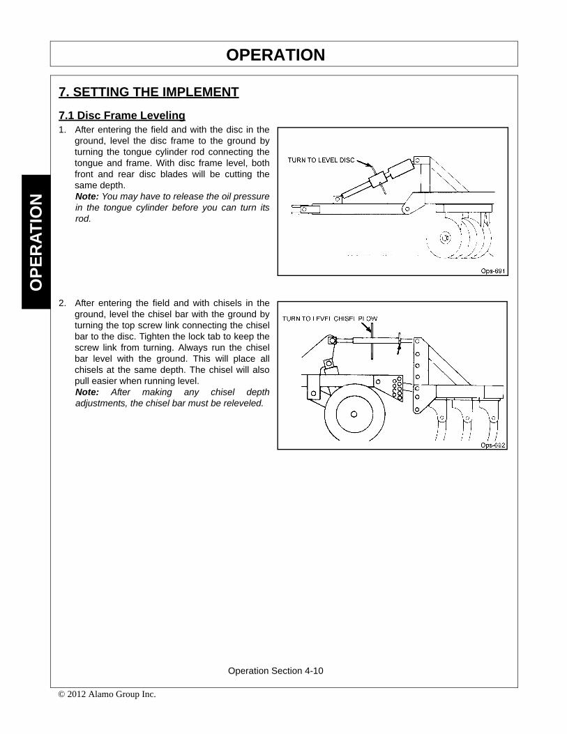
OPERATIONO
PE
RA
TIO
N
7. SETTING THE IMPLEMENT
7.1 Disc Frame Leveling1. After entering the field and with the disc in the
ground, level the disc frame to the ground byturning the tongue cylinder rod connecting thetongue and frame. With disc frame level, bothfront and rear disc blades will be cutting thesame depth.Note: You may have to release the oil pressurein the tongue cylinder before you can turn itsrod.
2. After entering the field and with chisels in theground, level the chisel bar with the ground byturning the top screw link connecting the chiselbar to the disc. Tighten the lock tab to keep thescrew link from turning. Always run the chiselbar level with the ground. This will place allchisels at the same depth. The chisel will alsopull easier when running level.Note: After making any chisel depthadjustments, the chisel bar must be releveled.
Operation Section 4-10
© 2012 Alamo Group Inc.
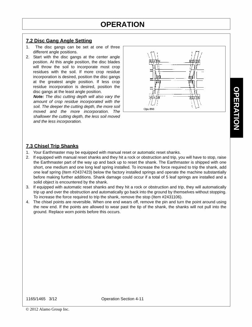
OPERATIONO
PE
RA
TIO
N
7.2 Disc Gang Angle Setting1. The disc gangs can be set at one of three
different angle positions.2. Start with the disc gangs at the center angle
position. At this angle position, the disc bladeswill throw the soil to incorporate most cropresidues with the soil. If more crop residueincorporation is desired, position the disc gangsat the greatest angle position. If less cropresidue incorporation is desired, position thedisc gangs at the least angle position.Note: The disc cutting depth will also vary theamount of crop residue incorporated with thesoil. The deeper the cutting depth, the more soilmoved and the more incorporation. Theshallower the cutting depth, the less soil movedand the less incorporation.
7.3 Chisel Trip Shanks1. Your Earthmaster may be equipped with manual reset or automatic reset shanks.2. If equipped with manual reset shanks and they hit a rock or obstruction and trip, you will have to stop, raise
the Earthmaster part of the way up and back up to reset the shank. The Earthmaster is shipped with oneshort, one medium and one long leaf spring installed. To increase the force required to trip the shank, addone leaf spring (Item #2437423) below the factory installed springs and operate the machine substantiallybefore making further additions. Shank damage could occur if a total of 5 leaf springs are installed and asolid object is encountered by the shank.
3. If equipped with automatic reset shanks and they hit a rock or obstruction and trip, they will automaticallytrip up and over the obstruction and automatically go back into the ground by themselves without stopping.To increase the force required to trip the shank, remove the stop (Item #2431106).
4. The chisel points are reversible. When one end wears off, remove the pin and turn the point around usingthe new end. If the points are allowed to wear past the tip of the shank, the shanks will not pull into theground. Replace worn points before this occurs.
1165/1465 3/12 Operation Section 4-11
© 2012 Alamo Group Inc.

OPERATIONO
PE
RA
TIO
N
8. PRE-OPERATION INSPECTION AND SERVICEBefore each use, a pre-operation inspection and service of the implement and tractor must be performed.This includes routine maintenance and scheduled lubrication, inspecting that all safety devices are equippedand functional, and performing needed repairs. DO NOT operate the unit if the pre-operation inspectionreveals any condition affecting safe operation. Perform repairs and replacement of damaged and missingparts as soon as noticed. By performing a thorough pre-operation inspection and service, valuable down timeand repair cost can be avoided. OPS-U-0029
Always disconnect the main PTO Driveline from the Tractor before performing service onthe Implement. Never work on the Implement with the tractor PTO driveline connected andrunning. Rotating Parts, Blades or Drivelines could turn without warning and causeimmediate entanglement, injury or death. (S3PT-11)
Periodically inspect all moving parts for wear and replace whennecessary with authorized service parts. Look for loose fasteners, wornor broken parts, and leaky or loose fittings. Make sure all pins havecotter pins and washers. Serious injury may occur from not maintainingthis machine in good working order. (SG-21)
Operation Section 4-12
© 2012 Alamo Group Inc.

OPERATIONO
PE
RA
TIO
N
8.1 Tractor Pre-Operation Inspection/ServiceRefer to the tractor operator’s manual to ensure acomplete pre-operation inspection and scheduledservice is performed according to themanufacturers recommendations. The followingare some of the items that require daily service andinspection:
• Tire condition/air pressure• Wheel lug bolts • Steering linkage• PTO shield • SMV sign is clean and visible• Tractor’s lights are clean and functional• Tractor Seat belt is in good condition • Tractor ROPS is in good condition• ROPS is in the raised position• No tractor oil leaks • Radiator free of debris • Engine oil level and condition• Engine coolant level and condition • Power brake fluid level • Power steering fluid level • Fuel condition and level • Sufficient lubrication at all lube points• Air filter condition OPS-U-0030
8.2 Implement Pre-Operation Inspection/ServiceBefore each implement use, a complete inspection and service is required to ensure the implement is in agood and safe working condition. Damaged and/or broken parts should be repaired and/or replacedimmediately. To ensure the implement is ready for operation, conduct the following. OPS-T-0002
The operator’s manual and safety signs affixed onthe unit contain important instructions on the safeand proper use of the equipment. Maintain theseimportant safety features on the implement in goodcondition to ensure the information is available tothe operator at all times.
• Ensure the manual canister is secured to theequipment with the operator’s manual inside.
• Ensure all safety signs are in place and legible.Replace missing, damaged, and illegibledecals. OPS-U- 0011
1165/1465 3/12 Operation Section 4-13
© 2012 Alamo Group Inc.

OPERATIONO
PE
RA
TIO
N
• Perform scheduled lubrication as detailed in themaintenance section.
• Ensure all decals are in place and legible.• Ensure that a properly rated safety tow chain is
equipped securing the implement to the tractor.OPS-T-0016
• Before operation check disc blades and spoolsforbreakage or cracking and replace if needed.
• Inspect Disc Gang and grease after every 8hour use.
• Check and Re-Adjust Disc Scraperswhenconditions change.
• Inspect all bolts and screws and tighten totherecommended torque. OPS-T-0017
• Inspect tire condition, wheel bearings, and lugnut torque.
• Inspect all bolts and screws and tighten to therecommended torque. OPS-T-0018
Operation Section 4-14
© 2012 Alamo Group Inc.

OPERATIONO
PE
RA
TIO
N
9. DRIVING THE TRACTOR AND IMPLEMENTSafe tractor transport requires the operator possess a thorough knowledge of the model being operated andprecautions to take while driving with an attached implement. Ensure the tractor has the capacity to handle theweight of the implement and the tractor operating controls are set for safe transport. To ensure safety whiledriving the tractor with an attached implement, review the following. OPS-U- 0012
10. OPERATING THE TRACTOR AND IMPLEMENTTHE OPERATOR MUST COMPLETELY UNDERSTAND HOW TO OPERATE THE TRACTOR ANDIMPLEMENT AND ALL CONTROLS BEFORE ATTEMPTING TO OPERATE. The operator must read andunderstand the Safety and Operation Sections of the implement and tractor operator’s manuals. Thesemanuals must be read and explained to any operator who cannot read. Never allow someone to operate theimplement and tractor without complete operating instructions.
Before starting any operation, the operator must become familiar with the area to be worked in and anyobstacles and hazards contained within to ensure safety to the operator, bystanders, and equipment. Specialattention should be paid to foreign debris, rough terrain, steep slopes, and passersby and animals in the area.OPS-U- 0015
Many varied objects, such as wire, cable, rope, or chains, can become entangled in therotating parts of the Implement. These objects could then swing outside the housing atgreater velocities than the blades. Such a situation is extremely hazardous and couldresult in serious injury or even death. Inspect the area for such objects before working inthe area. Remove any such objects from the site. Never allow the implement to contactsuch objects. (STL-6)
1165/1465 3/12 Operation Section 4-15
© 2012 Alamo Group Inc.

OPERATIONO
PE
RA
TIO
N
10.1 Foreign Debris HazardsBefore operating, inspect the area to make surethere are no foreign objects that the implementknives could hit or become entangled with.Remove all foreign objects and debris. If objectsare too big to remove, mark them clearly and besure to prevent the implement blades fromcontacting them.
If you hit a solid object or foreign debris, stop theimplement and tractor at once. Immediately idlethe engine speed and disengage the PTO. Wait forall implement rotating motion to stop, then raisethe implement and move the tractor andimplement off the object. Inspect the area andremove, or mark the location of the debris. Inspectthe condition of the implement and make anyneeded repairs immediately. Make sure the knivesare not damaged and the carrier is balancedbefore resuming operation.
Always wear your seat belt securely fastened andonly operate the tractor and implement with theROPS in the raised position. If the tractor or implement hits a tree stump, rock, or bump, a sudden movementcould throw you off of the seat and under the tractor and/or implement. The seat belt is your best protectionfrom falling off the tractor and the ROPS provides protection from being crushed during a tractor roll-over.OPS-T-0003
Extreme care should be taken when operating near loose objects such as gravel, rocks,wire, and other debris. Inspect the area before tilling. Foreign objects should be removedfrom the site to prevent machine damage and/or bodily injury or even death. Any objects
that cannot be removed must be clearly marked and carefully avoided by the operator. Stop operatingimmediately if blades strike a foreign object. Repair all damage and make certain rotor and blades are ingood condition before resuming operation. (STL-5)
10.2 Bystanders/Passersby PrecautionsIf a bystander comes within 300 feet of the tractor while the implement is being operated, stop the tractor atonce, idle the engine and disengage the PTO. Do not engage the PTO again until all bystanders are well pastthe 300 foot distance. OPS-T-0004
Operation Section 4-16
© 2012 Alamo Group Inc.

OPERATIONO
PE
RA
TIO
N
10.3 Engaging the Power Take Off (PTO)Before engaging the PTO, make certain that the area is clear of bystanders and passersby. The implementmust be completely lowered and the deck positioned at a safe operating height. NEVER engage the PTO withthe implement in the raised position.
Set the tractor engine speed at approximately 1,000 RPM before engaging the PTO. Shift the PTO control tothe on position, and slowly increase the engine speed until the PTO is operating at the rated speed. If youhear unusual noises or see or feel abnormal vibrations, disengage the PTO immediately. Inspect theimplement to determine the cause of the noise or vibration and repair the abnormality. OPS-U- 0027
Do not put hands or feet under Tiller deck. Blade Contact can result inserious injury or even death. Stay away until all motion has stoppedand the decks are securely blocked up. (STL-3)
10.4 PTO RPM and Ground SpeedGround speed for operating will depend upon the type of cultivation. Recommended speed for efficientimplement performance is between 2 and 5 mph. Operate the implement at its full rated PTO speed tomaintain knife speed for a clean operation. Refer to the tractor operator’s manual or the tractor instrumentpanel for the engine speed and gear to provide the required PTO and desired ground speed. Make sure thatthe implement is operating at its full rated speed before entering the area. If it becomes necessary totemporarily regulate engine speed, increase or decrease the throttle gradually.
Ground speed is achieved by transmission gear selection and not by the engine operating speed. Theoperator may be required to experiment with several gear range combinations to determine the best gear andrange which provides the most ideal performance from the implement and most efficient tractor operation. Asthe severity of operatin conditions increase, the ground speed should be decreased by selecting a lower gearto maintain the proper operating PTO speed. OPS-T-0006
Do not exceed the rated PTO speed for the Implement. Excessive PTO speeds can causeImplement driveline or blade failures resulting in serious injury or death. (SG-26)
1165/1465 3/12 Operation Section 4-17
© 2012 Alamo Group Inc.

OPERATIONO
PE
RA
TIO
N
10.6 Ball Valve OperationWhen the Earthmaster is lowered to the ground, the chisel shanks may start cutting before the disc gangs canbegin cutting stalks. This may result in uncut stalks wrapping around the shanks. This can be prevented bykeeping the tongue cylinder in the lowered position during field operation. A ball valve installed in the forwardport of the cylinder prevents the tongue cylinder from raising with the rear cylinder.
When the Earthmaster is in the field, move the cylinder lock, lower the machine so the tongue cylinder is in thelowered position and close the ball valve. The tongue cylinder will now stay in the lowered position at all times.
When the maximum ground clearance is required for road travel, lower the machine and open the ball valve.Now raise the machine and place the cylinder lock in the lock position and place the retainer pin in the top hole.Do not transport the Earthmaster with the tongue cylinder in the lowered position.
10.7 Using Chisel Bar on Tractor 3-Point Hitch
3-Point with Free-Link Hitch1. For Category II Hitch, use holes “C” and “E”.2. For Category II Hitch, use holes “B” and “E”.
3-Point with Quick Attaching Hitch1. For Category II Hitch, use holes “D” and “E”.2. For Category III Hitch, use holes “C” and “E”.
10.5 Operating the ImplementOnly operate the implement from the tractor operator’s seat with the seatbelt securely fastened. The tractormust be equipped with a ROPS in the raised position or a ROPS cab.
The implement is designed for horticultural, agricultural, or commercial applications cultivation. Maintainedknives will produce a better cultivation and require less power. Travel at a speed that allows the implementsufficient time to cultivate the ground and maintain the PTO operating speed to prevent overloading theimplement and tractor. Choose a driving pattern that provides the maximum pass length and minimizesturning.
Avoid operating in the reverse direction when possible. In situations where the implement must be backed toaccess areas, make sure there are no persons or other foreign debris behind the implement before operatingin reverse. When operating in reverse, operate the tractor and implement at a reduced ground speed toensure tractor and implement control is maintained. OPS-T-0005
Operation Section 4-18
© 2012 Alamo Group Inc.

OPERATIONO
PE
RA
TIO
N
10.8 Chisel Bar Gauge Wheels1. When optional gauge wheels are used, install
them between the two end shanks on bothsides as shown. (See Installation Instructions).
2. When using gauge wheels with chisel bar anddisc unit connected together, set the gaugewheels so that the disc wheels carry the weightand the gauge wheels keep the chisel bar fromrocking side-to-side.
3. When using the chisel bar connected to thetractor’s 3-Point Hitch, set the 3-Point hitchdepth control so the tractor tires carry theweight for traction and set the gauge wheels tokeep the chisel bar from rocking side-to-side.
10.9 Chisel Bar Coulters1. When optional coulters are used with chisel bar on tractor’s 3-point hitch, install one coulter in front of each
chisel shank as shown. (See Installation Instructions).2. Position the coulter cutting depth so that it will cut the crop residue in front of each chisel shank.
10.10 Shutting Down the ImplementTo shut down the implement, first bring the tractorto a complete stop. Then slow down the implementby reducing the engine speed before disengagingthe PTO. Wait for all motion to stop beforeproceeding to drive or shut down the tractor.
Park the tractor on a level surface, place thetransmission in park or neutral and apply theparking brake, lower the attached implement to theground, shut down the engine, remove the key, andwait for all motion to come to a complete stopbefore exiting the tractor. OPS-T-0007
11. DISCONNECTING THE IMPLEMENT FROM THE TRACTORBefore disconnecting the implement, the PTO must be disengaged and knife rotation at a complete stop.Move the implement to a level storage location and lower it to the ground. If the implement is not restingsecurely on the ground, block the implement up securely before attempting to disconnect it from the tractor.
Use extreme care to keep feet and hands from under the implement and clear of any pinch points caused bythe tractor hitch arms and implement pins. OPS-T-0008
1165/1465 3/12 Operation Section 4-19
© 2012 Alamo Group Inc.

OPERATIONO
PE
RA
TIO
N
Never stand or allow another person to stand between a running Tractor and the Implementwhen disconnecting the Implement from the Tractor 3-point hitch.
Always shut the Tractor completely down, place the transmission in park, and set theparking brake before you or anyone else attempts to connect or disconnect the Implementand Tractor hitches. (S3PT-15)
12. IMPLEMENT STORAGEProperly preparing and storing the implement at the end of the season is critical to maintaining its appearanceand to help ensure years of dependable service. The following are suggested storage procedures:
• Thoroughly clean all debris off the implement to prevent damage from rotting grass and standing water.• Lubricate all implement grease points and fill gearbox oil levels as detailed in the maintenance section.• Tighten all bolts and pins to the recommended torque.• Check the implement for worn and damaged parts. Perform repairs and make replacements immediately
so that the implement will be ready for use at the start of the next season.• Store the implement in a clean, dry place with the implement housing resting securely on blocks or at
ground level.• Keep the driveline yoke from sitting in water, dirt and other contaminants.• Use spray touch-up enamel where necessary to prevent rust and maintain the appearance of the
implement.
It is critical that driveline clutches slip when an obstacle or heavy load is encountered to avoid implement and/or tractor damage. If the implement sits outside for an extended period of time or is exposed to rain and/orhumid air, the clutch lining plates must be inspected to ensure they are not frozen together from rust orcorrosion. If the implement has been exposed to such conditions, at the start of each operating season, andany time it is suspected that the slip clutch plates may be frozen together, readjust the slip clutch as detailedin Seasonal Clutch Maintenance of the maintenance section in this manual. OPS-T-0010
Never allow children or other persons to ride on the Tractor or Implement.Falling off can result in serious injury or death. (SG-10)
13. TRANSPORTING THE TRACTOR AND IMPLEMENTInherent hazards of operating the tractor and implement and the possibility of accidents are not left behindwhen you finish working in an area. Therefore, the operator must employ good judgement and safe operationpractices when transporting the tractor and implement between locations. By using good judgement andfollowing safe transport procedures, the possibility of accidents while moving between locations can besubstantially minimized. OPS-U- 0017
Operation Section 4-20
© 2012 Alamo Group Inc.
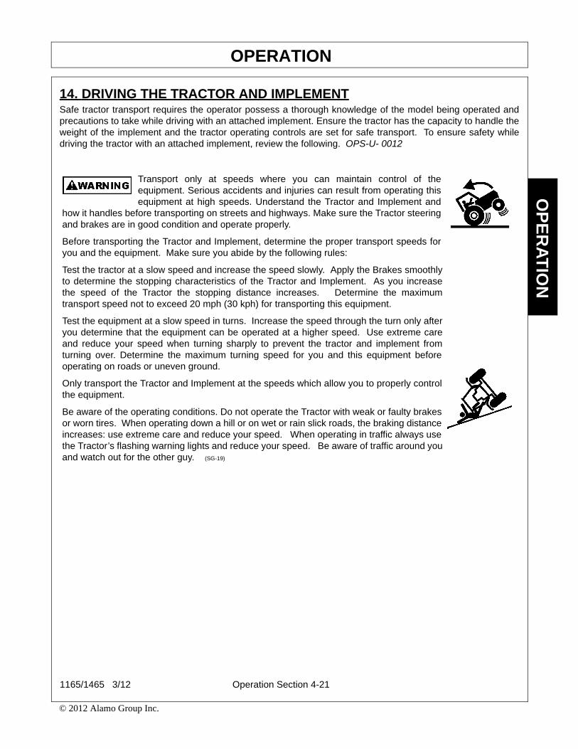
OPERATIONO
PE
RA
TIO
N
14. DRIVING THE TRACTOR AND IMPLEMENTSafe tractor transport requires the operator possess a thorough knowledge of the model being operated andprecautions to take while driving with an attached implement. Ensure the tractor has the capacity to handle theweight of the implement and the tractor operating controls are set for safe transport. To ensure safety whiledriving the tractor with an attached implement, review the following. OPS-U- 0012
Transport only at speeds where you can maintain control of theequipment. Serious accidents and injuries can result from operating thisequipment at high speeds. Understand the Tractor and Implement and
how it handles before transporting on streets and highways. Make sure the Tractor steeringand brakes are in good condition and operate properly.
Before transporting the Tractor and Implement, determine the proper transport speeds foryou and the equipment. Make sure you abide by the following rules:
Test the tractor at a slow speed and increase the speed slowly. Apply the Brakes smoothlyto determine the stopping characteristics of the Tractor and Implement. As you increasethe speed of the Tractor the stopping distance increases. Determine the maximumtransport speed not to exceed 20 mph (30 kph) for transporting this equipment.
Test the equipment at a slow speed in turns. Increase the speed through the turn only afteryou determine that the equipment can be operated at a higher speed. Use extreme careand reduce your speed when turning sharply to prevent the tractor and implement fromturning over. Determine the maximum turning speed for you and this equipment beforeoperating on roads or uneven ground.
Only transport the Tractor and Implement at the speeds which allow you to properly controlthe equipment.
Be aware of the operating conditions. Do not operate the Tractor with weak or faulty brakesor worn tires. When operating down a hill or on wet or rain slick roads, the braking distanceincreases: use extreme care and reduce your speed. When operating in traffic always usethe Tractor’s flashing warning lights and reduce your speed. Be aware of traffic around youand watch out for the other guy. (SG-19)
1165/1465 3/12 Operation Section 4-21
© 2012 Alamo Group Inc.

OPERATIONO
PE
RA
TIO
N
14.1 Transporting or ServicingWhen Earthmaster is in raised position for servicing or transporting, lock wheel struts andtongue cylinder to avoid injury. OPS-T-0020
• Lock the lift wheel strut in the raised positionby positioning the cylinder lock down overthe cylinder rod and secure it by placing theretainer pin in the bottom hole.
For field operation, raise the cylinder lock up offof the cylinder rod and secure it by placing theretainer pin in the top hole.
• Lock the tongue cylinder in the raisedposition by removing the pin handle and slidethe lock tube up against the cylinder andreinstall the pin handle in the bottom hole inthe lock tube. When the lock tube is not usedfor locking the cylinder, slide the lock tubedown away from the cylinder and install thepin handle in the opt hole of the lock tube.OPS-T-0021
Operation Section 4-22
© 2012 Alamo Group Inc.

OPERATIONO
PE
RA
TIO
N
Before transporting the tractor and implement, idlethe tractor engine, disengage the PTO and wait forall implement moving parts to come to a completestop. Once all implement parts are completelystopped, raise the implement to transport height.NOTE: When raising the implement, maintain 1”clearance between the driveline and implementdeck. If additional implement deck height isneeded for transport, disconnect the driveline fromthe tractor and secure its end to the implementdeck. The implement can then be raised to themaximum lift height. OPS-T-0011
14.2 Brake and Differential Lock SettingMake sure the tractor brakes are in good operatingcondition. Tractor brakes can be set to operateindependently allowing single rear wheel brakingaction or locked together to provide simultaneousrear wheel braking. FOR MOST DRIVING ANDOPERATING CONDITIONS, THE BRAKE PEDALSSHOULD BE LOCKED TOGETHER TO PROVIDETHE MOST EFFECTIVE BRAKING ACTION.
Always disengage the tractor differential lock whenturning. When engaged the differential lock willprevent or limit the tractor from turning. Duringnormal cutting conditions, locking the differentialprovides no benefit and should not be used. OPS-U- 0013
Be aware of the operating conditions. Do not operate the Tractor with weak or faulty brakes.When operating down a hill or on wet or rain slick roads, the braking distance increases; useextreme care and reduce your speed in these conditions. When operating in traffic, alwaysuse the Tractor’s flashing warning lights and reduce your speed. Be aware of traffic aroundyou and watch out for the other guy.
1165/1465 3/12 Operation Section 4-23
© 2012 Alamo Group Inc.
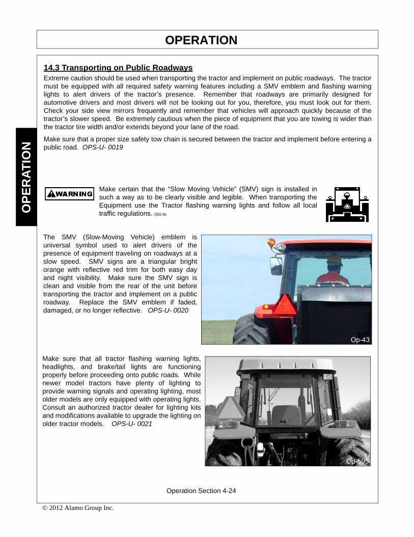
OPERATIONO
PE
RA
TIO
N
14.3 Transporting on Public RoadwaysExtreme caution should be used when transporting the tractor and implement on public roadways. The tractormust be equipped with all required safety warning features including a SMV emblem and flashing warninglights to alert drivers of the tractor’s presence. Remember that roadways are primarily designed forautomotive drivers and most drivers will not be looking out for you, therefore, you must look out for them.Check your side view mirrors frequently and remember that vehicles will approach quickly because of thetractor’s slower speed. Be extremely cautious when the piece of equipment that you are towing is wider thanthe tractor tire width and/or extends beyond your lane of the road.
Make sure that a proper size safety tow chain is secured between the tractor and implement before entering apublic road. OPS-U- 0019
Make certain that the “Slow Moving Vehicle” (SMV) sign is installed insuch a way as to be clearly visible and legible. When transporting theEquipment use the Tractor flashing warning lights and follow all localtraffic regulations. (SG-6)
The SMV (Slow-Moving Vehicle) emblem isuniversal symbol used to alert drivers of thepresence of equipment traveling on roadways at aslow speed. SMV signs are a triangular brightorange with reflective red trim for both easy dayand night visibility. Make sure the SMV sign isclean and visible from the rear of the unit beforetransporting the tractor and implement on a publicroadway. Replace the SMV emblem if faded,damaged, or no longer reflective. OPS-U- 0020
Make sure that all tractor flashing warning lights,headlights, and brake/tail lights are functioningproperly before proceeding onto public roads. Whilenewer model tractors have plenty of lighting toprovide warning signals and operating lighting, mostolder models are only equipped with operating lights.Consult an authorized tractor dealer for lighting kitsand modifications available to upgrade the lighting onolder tractor models. OPS-U- 0021
Operation Section 4-24
© 2012 Alamo Group Inc.

OPERATIONO
PE
RA
TIO
N
When operating on public roads, have consideration for other road users. Pull to the side of the roadoccasionally to allow all following traffic to pass. Do not exceed the legal speed limit set in your country foragricultural tractors. Always stay alert when transporting the tractor and implement on public roads. Usecaution and reduce speed if other vehicles or pedestrians are in the area. OPS-T-0013
Reduce speed before turning or applying the brakes.Ensure that both brake pedals are locked togetherwhen operating on public roads. OPS-U- 0023
1165/1465 3/12 Operation Section 4-25
© 2012 Alamo Group Inc.


Maintenance Section 5-1
MAINTENANCE SECTION

MAINTENANCEM
AIN
TE
NA
NC
E
GENERAL MAINTENANCE
1. Grease disc gang bearings daily.
2. Grease cylinder pins every 8 hours.
3. Grease lift wheels strut pivots every 8 hours.
4. Grease automatic reset shanks every 8 hours if Earthmaster is equipped with them.
5. Keep disc gang bolt tight. Torque to 800-850 ft./lbs. Check all bolts for tightness periodically.
6. Keep tire inflated to 45 PSI.
7. Check wheel lug bolts after first 4 hours of use and tighten if necessary. Check periodically.
8. Repack transport wheels, gauge wheels and coulter bearings yearly.
PROPER TORQUE CHART FOR FASTENERS
The chart lists the correct tightening torque for fasteners. When bolts are to be tightened or replaced, refer tothis chart to determine the grade of bolts and the proper torque except when specific torque values areassigned in manual text.
RECOMMENDED TORQUE IN FOOT POUNDS UNLESS OTHERWISE STATED IN THE MANUAL*
NOTE: These values apply to fasteners as received from supplier, dry or when lubricated with normal engineoil. They do not apply if special graphited or molydisulphide greases or other extreme pressure lubricants areused. This applies to both UNF fine and UNC coarse threads.
1165/1465 03/12 Maintenance Section 5-2
© 2012 Alamo Group Inc.

MAINTENANCEM
AIN
TE
NA
NC
E
1165/1465 03/12 Maintenance Section 5-3
© 2012 Alamo Group Inc.

EarthMasterLIMITED WARRANTY
1. LIMITED WARRANTIES
1.01. EarthMaster warrants for one year from the purchase date to the original non-commercial, governmental, or municipal purchaser(“Purchaser”) and warrants for six months to the original commercial or industrial purchaser (“Purchaser”) that the goodspurchased are free from defects in material or workmanship.
1.02. Manufacturer will replace for the Purchaser any part or parts found, upon examination at one of its factories, to be defective undernormal use and service due to defects in material or workmanship.
1.03. This limited warranty does not apply to any part of the goods which has been subjected to improper or abnormal use, negligence,alteration, modification, or accident, damaged due to lack of maintenance or use of wrong fuel, oil, or lubricants, or which hasserved its normal life. This limited warranty does not apply to any part of any internal combustion engine, or expendable itemssuch as blades, shields, guards, or pneumatic tires except as specifically found in your Operator’s Manual.
1.04. Except as provided herein, no employee, agent, Dealer, or other person is authorized to give any warranties of any nature onbehalf of Manufacturer.
2. REMEDIES AND PROCEDURES.
2.01. This limited warranty is not effective unless the Purchaser returns the Registration and Warranty Form to Manufacturer within 30days of purchase.
2.02. Purchaser claims must be made in writing to the Authorized Dealer (“Dealer”) from whom Purchaser purchased the goods or anapproved Authorized Dealer (“Dealer”) within 30 days after Purchaser learns of the facts on which the claim is based.
2.03. Purchaser is responsible for returning the goods in question to the Dealer.
2.04. If after examining the goods and/or parts in question, Manufacturer finds them to be defective under normal use and service due todefects in material or workmanship, Manufacturer will:
(a)Repair or replace the defective goods or part(s) or
(b)Reimburse Purchaser for the cost of the part(s) and reasonable labor charges (as determined by Manufacturer) if Purchaserpaid for the repair and/or replacement prior to the final determination of applicability of the warranty by Manufacturer.
The choice of remedy shall belong to Manufacturer.
2.05. Purchaser is responsible for any labor charges exceeding a reasonable amount as determined by Manufacturer and for returningthe goods to the Dealer, whether or not the claim is approved. Purchaser is responsible for the transportation cost for the goods orpart(s) from the Dealer to the designated factory.
3. LIMITATION OF LIABILITY.
3.01. MANUFACTURER DISCLAIMS ANY EXPRESS (EXCEPT AS SET FORTH HEREIN) AND IMPLIED WARRANTIES WITHRESPECT TO THE GOODS INCLUDING, BUT NOT LIMITED TO, MERCHANTABILITY AND FITNESS FOR APARTICULAR PURPOSE.
3.02. MANUFACTURER MAKES NO WARRANTY AS TO THE DESIGN, CAPABILITY, CAPACITY, OR SUITABILITY FOR USE OFTHE GOODS.
3.03. EXCEPT AS PROVIDED HEREIN, MANUFACTURER SHALL HAVE NO LIABILITY OR RESPONSIBILITY TO PURCHASER ORANY OTHER PERSON OR ENTITY WITH RESPECT TO ANY LIABILITY, LOSS, OR DAMAGE CAUSED OR ALLEGED TO BECAUSED DIRECTLY OR INDIRECTLY BY THE GOODS INCLUDING, BUT NOT LIMITED TO, ANY INDIRECT, SPECIAL,CONSEQUENTIAL, OR INCIDENTAL DAMAGES RESULTING FROM THE USE OR OPERATION OF THE GOODS OR ANYBREACH OF THIS WARRANTY. NOT WITHSTANDING THE ABOVE LIMITATIONS AND WARRANTIES, MANUFACTURER’SLIABILITY HEREUNDER FOR DAMAGES INCURRED BY PURCHASER OR OTHERS SHALL NOT EXCEED THE PRICE OFTHE GOODS.
3.04. NO ACTION ARISING OUT OF ANY CLAIMED BREACH OF THIS WARRANTY OR TRANSACTIONS UNDER THISWARRANTY MAY BE BROUGHT MORE THAN TWO (2) YEARS AFTER THE CAUSE OF ACTION HAS OCCURRED.
4. MISCELLANEOUS.
4.01. Proper Venue for any lawsuits arising from or related to this limited warranty shall be only in Guadalupe County, Texas.
4.02. Manufacturer may waive compliance with any of the terms of this limited warranty, but no waiver of any terms shall be deemed tobe a waiver of any other term.
4.03. If any provision of this limited warranty shall violate any applicable law and is held to be unenforceable, then the invalidity of suchprovision shall not invalidate any other provisions herein.
4.04. Applicable law may provide rights and benefits to purchaser in addition to those provided herein.
KEEP FOR YOUR RECORDS
ATTENTION: Purchaser should fill in the blanks below for his reference when buying repair parts and/or for proper machine identification whenapplying for warranty.
EarthMaster Implement Model ___________________________ Serial Number ________________________
Date Purchased ______________________________________ Dealer ______________________________
ATTENTION:
READ YOUR OPERATOR'S MANUAL
EarthMaster1020 S Sangamon Ave. Gibson City, IL 60936217-784-4261

TO THE OWNER/OPERATOR/DEALER
To keep your implement running efficiently and safely, read your manual thoroughly and follow these directionsand the Safety Messages in this Manual. The Table of Contents clearly identifies each section where you caneasily find the information you need.
The OCCUPATIONAL SAFETY AND HEALTH ACT (1928.51 Subpart C) makes these minimum safetyrequirements of tractor operators:
REQUIRED OF THE OWNER:1. Provide a Roll-Over-Protective Structure that meets the requirements of this Standard; and2. Provide Seat belts that meet the requirements of this paragraph of this Standard and SAE J4C; and3. Ensure that each employee uses such Seat belt while the tractor is moving; and4. Ensure that each employee tightens the Seat belt sufficiently to confine the employee to the protected area
provided by the ROPS5. Keep Children away from danger all day, everyday.
REQUIRED OF THE OPERATOR:1. Securely fasten seat belt if the tractor has a ROPS.2. Where possible, avoid operating the tractor near ditches, embankments, and holes.3. Reduce speed when turning, crossing slopes, and on rough, slick, or muddy surfaces.4. Stay off slopes too steep for safe operation.5. Watch where you are going - especially at row ends, on roads, and around trees.6. Do not permit others to ride.7. Operate the tractor smoothly - no jerky turns, starts, or stops.8. Hitch only to the drawbar and hitch points recommended by the tractor manufacturer.9. When the tractor is stopped, set brakes securely and use park lock, if available.

EM 1165-1465-SOM-03/12 P/N 4353CPrinted U.S.A
1165-1465TILLAGE
Related Documents