Terraprobe Consulting Geotechnical & Environmental Engineering Construction Materials Inspection & Testing Terraprobe Inc. Greater Toronto Hamilton – Niagara Central Ontario Northern Ontario 11 Indell Lane 903 Barton Street, Unit 22 220 Bayview Drive, Unit 25 1012 Kelly Lake Rd., Unit 1 Brampton, Ontario L6T 3Y3 Stoney Creek, Ontario L8E 5P5 Barrie, Ontario L4N 4Y8 Sudbury, Ontario P3E 5P4 (905) 796-2650 Fax: 796-2250 (905) 643-7560 Fax: 643-7559 (705) 739-8355 Fax: 739-8369 (705) 670-0460 Fax: 670-0558 [email protected] [email protected] [email protected] [email protected] www.terraprobe.ca GEOTECHNICAL REPORT DERRY ROAD AND ARGENTIA ROAD INTERSECTION IMPROVEMENTS REGION OF PEEL, ONTARIO PREPARED FOR: HDR Corporation 255 Adelaide Street West Toronto, Ontario M5H 1X9 Attention: Mr. Andrew O’Connor File No. 11-13-3148 February 03, 2015 © Terraprobe Inc. Distribution: 2 Copies - HDR Corporation 1 Copy - Terraprobe Inc., Brampton

Welcome message from author
This document is posted to help you gain knowledge. Please leave a comment to let me know what you think about it! Share it to your friends and learn new things together.
Transcript

TerraprobeConsulting Geotechnical & Environmental Engineering
Construction Materials Inspection & Testing
Terraprobe Inc. Greater Toronto Hamilton – Niagara Central Ontario Northern Ontario11 Indell Lane 903 Barton Street, Unit 22 220 Bayview Drive, Unit 25 1012 Kelly Lake Rd., Unit 1Brampton, Ontario L6T 3Y3 Stoney Creek, Ontario L8E 5P5 Barrie, Ontario L4N 4Y8 Sudbury, Ontario P3E 5P4(905) 796-2650 Fax: 796-2250 (905) 643-7560 Fax: 643-7559 (705) 739-8355 Fax: 739-8369 (705) 670-0460 Fax: [email protected] [email protected] [email protected] [email protected]
www.terraprobe.ca
GEOTECHNICAL REPORT
DERRY ROAD AND ARGENTIA ROAD INTERSECTION IMPROVEMENTS
REGION OF PEEL, ONTARIO
PREPARED FOR: HDR Corporation 255 Adelaide Street West Toronto, Ontario M5H 1X9 Attention: Mr. Andrew O’Connor
File No. 11-13-3148 February 03, 2015
© Terraprobe Inc. Distribution: 2 Copies - HDR Corporation 1 Copy - Terraprobe Inc., Brampton

HDR Corporation February 03, 2015 Intersection Improvements, Derry and Argentia Roads File No. 11-13-3148
Terraprobe Inc i
TABLE OF CONTENTS
1.0 INTRODUCTION ....................................................................................................................... 1
2.0 PROJECT AND SITE DESCRIPTION ...................................................................................... 1
3.0 SITE INVESTIGATION AND FIELD TESTING ......................................................................... 1
4.0 SUBSURFACE CONDITIONS .................................................................................................. 2
4.1 General ......................................................................................................................... 2 4.1.1 Pavement Structure ...................................................................................................... 3 4.1.2 Topsoil .......................................................................................................................... 4 4.1.3 Concrete ....................................................................................................................... 4 4.1.4 Fill – Sand and Gravel to Silty Sand ............................................................................. 4 4.1.5 Fill – Silty Clay .............................................................................................................. 4 4.1.6 Till - Silty Clay ............................................................................................................... 5 4.2 Ground Water Levels .................................................................................................... 6
5.0 DISCUSSION AND RECOMMENDATIONS ............................................................................. 7
5.1 General ......................................................................................................................... 7 5.2 Pavement Condition ..................................................................................................... 7 5.3 Traffic Data ................................................................................................................... 7 5.4 Pavement Designs ....................................................................................................... 8 5.4.1 Pavement Structures (New Construction – Widening) ................................................. 9 5.4.2 Existing Pavement Rehabilitation ................................................................................. 9
6.0 RECOMMENDATIONS AND COSTRUCTION FEATURES .................................................. 10
6.1 Pavement Structure and Material Types .................................................................... 10 6.2 Padding ....................................................................................................................... 10 6.3 Asphalt Cement Grade ............................................................................................... 10 6.4 Routing and Sealing & Tack Coat .............................................................................. 10 6.5 Key-in Detail ............................................................................................................... 10 6.6 Pavement Crossfall .................................................................................................... 11 6.7 Pavement Tapers ....................................................................................................... 11 6.8 Subdrains .................................................................................................................... 11 6.9 Compaction of Base & Sub-Base Materials ............................................................... 11 6.10 Reuse of Existing Granular Fill ................................................................................... 11 6.11 Excavations ................................................................................................................ 11 6.12 Stripping ...................................................................................................................... 12 6.13 Subgrade Preparation ................................................................................................ 12 6.14 Frost Protection .......................................................................................................... 12 6.15 Backfill ........................................................................................................................ 12
7.0 SOIL CHEMICAL ANALYSIS ................................................................................................. 13
8.0 LIMITATIONS AND RISK ....................................................................................................... 13
8.1 Procedures ................................................................................................................. 13 8.2 Changes in Site and Scope ........................................................................................ 14
9.0 CLOSURE ............................................................................................................................... 14

HDR Corporation February 03, 2015 Intersection Improvements, Derry and Argentia Roads File No. 11-13-3148
Terraprobe Inc ii
REFERENCES LIST OF FIGURES Figure 1 Site Location Plan Figures 2 and 3 Site Photographs Figure 4 Borehole Location Plan APPENDICES APPENDIX A Borehole Logs Abbreviations and Terminology Terraprobe Borehole and Core Logs SPL Borehole and Core Logs APPENDIX B Laboratory Test Results Figure B1 Grain Size Distribution – Granular Base/Subbase Figure B2 Grain Size Distribution – Silty Clay Till APPENDIX C Flexible Pavement Condition Evaluation Forms APPENDIX D Certificate of Chemical Analysis (Soil Chemistry)

HDR Corporation February 03, 2015 Intersection Improvements, Derry and Argentia Roads File No. 11-13-3148
Terraprobe Inc 1
1.0 INTRODUCTION
Terraprobe Inc. (Terraprobe) has been retained by HDR Corporation (HDR) to provide
geotechnical engineering services in support of the proposed intersection improvements at Derry
Road and Argentia Road in the Region of Peel, Ontario. A site location plan is provided as
Figure 1 and site photographs are presented in Figures 2 and 3.
The scope of work for the geotechnical engineering services is outlined in Terraprobe’s proposal
titled “Schedule ‘B’ Municipal Class EA for Derry Road and Argentia Road From 300m of All
Quadrants of the Intersection, RFP 2013-261P, City of Mississauga, The Regional Municipality of Peel” dated May 10, 2013.
The purpose of this investigation was to explore the subsurface conditions within the study area by
borehole drilling and pavement coring, in-situ testing and laboratory testing on soil samples. The
data obtained from this investigation was used to provide Borehole Location Plan, Borehole Logs,
laboratory test results, a description of the subsurface conditions and geotechnical design
recommendations.
A geotechnical investigation was carried out for a section of Derry Road within the current project
limits and selected data from this investigation is provided in this report. The following document is
referenced in the preparation of this report:
SPL Consultants Limited, “Geotechnical Investigation, Derry Road between Argentia &
Millcreek, City of Mississauga, Ontario” Project No. 592-1078, dated February 25, 2013.
2.0 PROJECT AND SITE DESCRIPTION
Derry Road is an east/west oriented arterial road that intersects Argentia Road. This intersection is
located in a full developed area with hotels at the northeast and southeast quadrants and
commercial enterprises at the remaining quadrants of the intersection. A Highway 401 overpass
and a railway bridge are located at the east and west limits of the study area respectively. Both
roadways currently conform to an urban cross-section.
The purpose of this study is to identify long term improvements on the intersection for the horizon
year of 2031 and, geotechnical consulting services are required to support the design.
3.0 SITE INVESTIGATION AND FIELD TESTING
The site investigation and field testing were carried out on June 6 and 9, 2014, and consisted of
drilling and sampling twenty eight boreholes to depths ranging from approximately 0.6 m to 1.8 m
below ground surface including asphalt pavement coring at four locations. The approximate
borehole and corehole locations are shown on Figure 4 with the approximate locations of SPL’s
Boreholes from the referenced report.
The borehole and corehole locations were marked in the field by Terraprobe’s field staff in relation
to existing features shown on the base plan provided by HDR. Utility clearances and permits were
obtained by Terraprobe prior to drilling.
On the existing roadways the boreholes were drilled with a CME 75 truck-mounted drill rig supplied
and operated by Strong Soil Search of Claremont, Ontario. These borings were extended through
the asphalt pavement and the overburden soils using solid stem augering techniques and soil

HDR Corporation February 03, 2015 Intersection Improvements, Derry and Argentia Roads File No. 11-13-3148
Terraprobe Inc 2
samples were obtained at selected intervals of depth using a 50 mm outer diameter (O.D.) split-
spoon sampler in conjunction with the Standard Penetration Test (SPT) procedures as specified in
ASTM Method D15861. Cores of the existing pavement were obtained with a 150 mm diameter
core barrel.
The boreholes in the boulevard areas were extended manually by advancing a split-spoon sampler
with portable hand operated vibratory equipment (Pionjar) supplied and operated by Sonic Soil
Sampling of Concord, Ontario. Ground water conditions in the open boreholes were observed
during and immediately following the drilling operations.
A member of Terraprobe’s technical staff observed and recorded the borehole drilling and the
sampling operations on a full-time basis. The soil samples were visually inspected in the field,
placed in labelled plastic containers and transferred to Terraprobe’s Brampton laboratory for further
examination and testing.
The recovered soil samples were subjected to Visual Identification (VI) and select soil samples
were subjected to a laboratory testing programme consisting of natural water content and grain
size distribution in accordance with MTO and/or ASTM Standards as appropriate. The results of
the soil testing program are presented on the Borehole Logs in Appendix A and on the figures in
Appendix B. Two soil samples were also submitted to Agat Laboratories for soil chemical testing to
assess soil disposal options for excess soils generated during construction. The results of the soil
chemical tests are provided in Appendix D.
A visual pavement condition survey of Derry Road and Argentia Road was completed in
August 2014. The survey was conducted in accordance with the procedures outlined in the
Ministry of Transportation of Ontario (MTO) Manual for Condition Rating of Flexible Pavements -
Distress Manifestations (SP-024). The Flexible Pavement Condition Evaluation Forms are
included in Appendix C.
4.0 SUBSURFACE CONDITIONS
4.1 General
Reference is made to the Borehole Logs and Core Logs in Appendix A. Details of the encountered
pavement structure and soil stratigraphy are provided in this appendix. An overall description of
the pavement structure and soil stratigraphy is given in the following paragraphs. However; the
factual data presented in the Borehole Logs and Core Logs governs any interpretation of the site
conditions. The subsurface conditions will vary between and beyond the borehole locations.
1 ASTM D1586 – Standard Test Method for Standard Penetration Tests and Split Barrel Sampling of Soils.

HDR Corporation February 03, 2015 Intersection Improvements, Derry and Argentia Roads File No. 11-13-3148
Terraprobe Inc 3
4.1.1 Pavement Structure
The average pavement structures of the roadways are summarized below.
Pavement Component
Derry Road East Leg
Derry Road West Leg
Argentia Road North Leg
Argentia Road South Leg
HMA (mm) 165 120* 145 170
Granular (mm) 630 * 525 585
Total (mm) 795 * 670 755
* The average asphalt thickness was derived from SPL Core Logs. Information on pavement granular thickness was not provided.
The granular material comprising the base/subbase courses of the roadways generally consists of
gravelly sand to sand and gravel fill material. The pavement boreholes extended through the south
leg of Argentia Road (Boreholes 16, 17, 22 and 23) encountered beneath the asphaltic concrete a
sand layer that ranges from 560 mm to 620 mm in thickness. The locations, fill thickness and the
range of SPT N-values and moisture contents are summarized below.
Gravelly Sand to Sand and Gravel Fill
Borehole No.
Fill Thickness(m)
Range of SPT N-values (blows/0.3m)
Range of Moisture Content (% by weight)
8 0.64 41 -
9 1.04 21 – 48 -
12 0.89 23 – 46 -
13 0.62 49 -
16 0.62 28 4
17 0.60 31 -
22 0.56 23 -
23 0.57 14 -
26 0.43 17 -
27 0.41 17 -
31 0.60 21 -
34 0.65 19 5
Two (2) samples of this gravelly sand to sand and gravel fill were subjected to grain size
distribution tests and the results are presented in Figure B1 in Appendix B. The results are
compared to the Ontario Provincial Standards (OPSS) Granular A and Granular B Type I
specifications. Based on the SPT N-values the relative density of the gravelly sand, to sand and
gravel fill is described as generally compact with occasional dense zones.
HDR Corporation February 03, 2015 Intersection Improvements, Derry and Argentia Roads File No. 11-13-3148
Terraprobe Inc 4
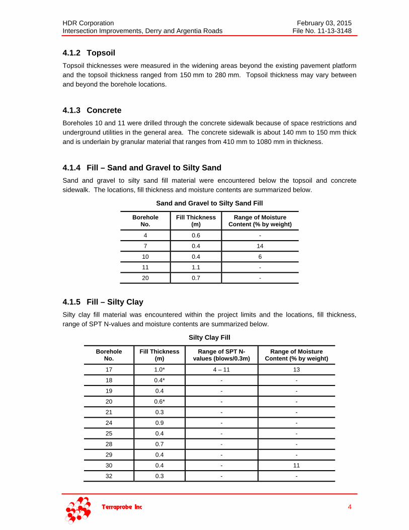
4.1.2 Topsoil
Topsoil thicknesses were measured in the widening areas beyond the existing pavement platform
and the topsoil thickness ranged from 150 mm to 280 mm. Topsoil thickness may vary between
and beyond the borehole locations.
4.1.3 Concrete
Boreholes 10 and 11 were drilled through the concrete sidewalk because of space restrictions and
underground utilities in the general area. The concrete sidewalk is about 140 mm to 150 mm thick
and is underlain by granular material that ranges from 410 mm to 1080 mm in thickness.
4.1.4 Fill – Sand and Gravel to Silty Sand
Sand and gravel to silty sand fill material were encountered below the topsoil and concrete
sidewalk. The locations, fill thickness and moisture contents are summarized below.
Sand and Gravel to Silty Sand Fill
Borehole No.
Fill Thickness(m)
Range of Moisture Content (% by weight)
4 0.6 -
7 0.4 14
10 0.4 6
11 1.1 -
20 0.7 -
4.1.5 Fill – Silty Clay
Silty clay fill material was encountered within the project limits and the locations, fill thickness,
range of SPT N-values and moisture contents are summarized below.
Silty Clay Fill
Borehole No.
Fill Thickness(m)
Range of SPT N-values (blows/0.3m)
Range of Moisture Content (% by weight)
17 1.0* 4 – 11 13
18 0.4* - -
19 0.4 - -
20 0.6* - -
21 0.3 - -
24 0.9 - -
25 0.4 - -
28 0.7 - -
29 0.4 - -
30 0.4 - 11
32 0.3 - -

HDR Corporation February 03, 2015 Intersection Improvements, Derry and Argentia Roads File No. 11-13-3148
Terraprobe Inc 5
Borehole No.
Fill Thickness(m)
Range of SPT N-values (blows/0.3m)
Range of Moisture Content (% by weight)
33 0.4 - -
34 0.4 10 -
*Borehole termination depth.
Based on the SPT N-values, the consistency of the silty clay fill is described as firm to stiff.
4.1.6 Till - Silty Clay
A silty clay till deposit was encountered across the site. Summarized below are the locations
where these soils were found, their explored depths, range of SPT N-values and moisture contents.
Silty Clay Till
Borehole No.
Depth of Deposit (m)
Range of SPT N-values (blows/0.3m)
Range of Moisture Content (% by weight)
4 1.8* - -
7 1.8* - 14
8 1.6* 23 – 72/22.5 cm -
9 1.8* 33 -
10 1.8* - 15
11 1.7* - -
12 1.8* 32 -
13 1.8* 13 – 26 -
15 0.9* - -
16 1.7* 12 – 74/27.5 cm 11 - 16
19 1.5* - -
21 1.8* - -
22 1.6* 10 – 99/22.5 cm -
23 1.8* 11 – 15 -
24 1.8* - -
25 1.1* - -
26 1.8* 65 – 77 -
27 1.8* 55 – 59 -
28 1.5* - -
29 1.1* - -
30 1.7* - 14
31 1.8* 22 – 45 -
32 1.1* - -
33 1.1* - -
34 1.8* 22 -
*Borehole termination depth.

HDR Corporation February 03, 2015 Intersection Improvements, Derry and Argentia Roads File No. 11-13-3148
Terraprobe Inc 6
Two samples of the silty clay till were subjected to grain size distribution tests and the results are
presented in Figure B2 in Appendix B. These results show a soil matrix consisting of 0 – 2 %
gravel, 17 – 22 % sand, 51 – 53 % silt and 25 – 30 % clay sized particles. Till soils can also be
expected to contain random cobble and boulder inclusions.
Based on the SPT N-values the consistency of the silty clay till is described as stiff to hard.
4.2 Ground Water Levels
No free water was encountered in any of the boreholes during drilling. The ground water level is
expected to fluctuate seasonally and will be influenced by major weather events and perched water
can be expected to occur where surficial layers of gravelly sands are underlain by relatively
impermeable silty clay soils.

HDR Corporation February 03, 2015 Intersection Improvements, Derry and Argentia Roads File No. 11-13-3148
Terraprobe Inc 7
5.0 DISCUSSION AND RECOMMENDATIONS
5.1 General
This section of the report presents an interpretation of the factual geotechnical data and provides
geotechnical design recommendations. These discussions and recommendations are based on
our understanding of the project, and our interpretation of the factual data obtained from the current
and previous subsurface investigations.
Where comments are made on construction, they are provided to highlight those aspects that could
affect the design of the project, and for which special provisions or operational constraints may be
required in the Contract Documents. Those requiring information on the aspects of construction
should make their own interpretation and assessment of the geotechnical information provided, as
such interpretation may affect equipment selection, proposed construction methods, scheduling
and the like.
HDR’s design drawings illustrate that the intersection is to be upgraded by providing additional
turning lanes on each leg of the intersection. The east and west legs of Derry Road will be
widened on the south sides to accommodate additional left turn lanes. The south leg of Argentia
Road will be widened on the east side to accommodate a new northbound through lane. The north
leg of Argentia Road will be widened on the west side to accommodate a right turn lane.
5.2 Pavement Condition
A visual pavement condition evaluation of Derry Road and Argentia Road was completed in
August 2014. The survey was conducted in accordance with the procedures outlined in the
Ministry of Transportation of Ontario (MTO) Manual for Condition Rating of Flexible Pavements -
Distress Manifestations (SP-024). The Pavement Condition Evaluation Forms are included in
Appendix C. Summarized below are the observed pavement distresses and the overall pavement
condition of the evaluated pavement sections.
Summarized Pavement Conditions
Section Overall Condition General Distresses
Derry Road Sta. 9+720 to Sta. 10+166
PCR = 70, RCR = 7Good
Intermittent slight raveling and coarse aggregate loss. Intermittent slight wheel track rutting. Intermittent slight single and multiple longitudinal wheel
track cracking. Intermittent slight transverse cracking.
Argentia Road Sta. 1+790 to Sta. 2+280
PCR = 70, RCR = 7Good
Frequent moderate raveling and coarse aggregate loss. Intermittent slight wheel track rutting. Intermittent slight single and multiple longitudinal wheel
track cracking. Intermittent moderate alligator pavement edge cracking. Intermittent slight transverse cracking.
5.3 Traffic Data
The AADT values, annual growth rates and percentage of commercial vehicles used for the
pavement design were provided by HDR. This traffic data and the derived Equivalent Single Axle
Loads (ESALs) are provided in the following table.

HDR Corporation February 03, 2015 Intersection Improvements, Derry and Argentia Roads File No. 11-13-3148
Terraprobe Inc 8
Traffic Data and ESAL’s
Parameters Derry Road Argentia Road
Projected AADT (2015) 40,730 15,520
Projected AADT (2021) 43,240 16,480
Projected AADT (2031) 47,730 18,180
Annual Growth Rate (2015 – 2031) 1% 1%
Percent Commercial Vehicles 5% 5%
Design ESALs (2021) 2,100,000 516,300
Design ESALs (2031) 5,050,000 1,450,000
5.4 Pavement Designs
The pavement structures were designed based on the traffic information provided by HDR and the
data obtained from the field investigations. Pavement designs were carried out for new
construction (widening) as well as rehabilitation of the existing roadway.
The following references and guidelines were used for the pavement designs.
MTO’s “Adaptation and Verification of AASHTO Pavement Design Guide for Ontario
Conditions, MI-183”, March 19, 2008; and
American Association of State Highway and Transportation Officials, “AASHTO Guide for
Design of Pavement Structures”, 1993.
The pavement design parameters are summarized in the following table.
AASHTO Pavement Design Parameters
Design Parameter Values
Initial/Terminal Serviceability Index Pi = 4.2 Pt = 2.2
Loss in Serviceability Index 2.0
Desired Reliability (R %) and Standard Deviation (SD) R = 85 SD = 0.45
Estimated Resilient Modulus of Subgrade Soil (MPa) 35
Layer Coefficients of Hot Mix Asphalt (HMA) New HMA = 0.42 Existing HMA = 0.25 to 0.30
Layer Coefficient of Granular Materials
Gran. A = 0.14 Gran. B Type I = 0.09 Existing Granular ‘A’ Material = 0.10 to 0.14
Existing Granular ‘B’ Material = 0.08
Drainage Coefficient of Granular Materials New Granular = 1.0 Existing Granular = 0.9 to 1.0

HDR Corporation February 03, 2015 Intersection Improvements, Derry and Argentia Roads File No. 11-13-3148
Terraprobe Inc 9
5.4.1 Pavement Structures (New Construction – Widening)
Based on our pavement condition survey both roads are in good condition and have performed well
over the years which likely indicates a structurally adequate pavement structure. Furthermore,
since the turning traffic volume is less than the traffic volume in the main lanes; a pavement
structure similar to the main lanes of the roadways will suffice. Existing and new pavement
structures of at least equal thicknesses are also required to provide positive lateral drainage across
the pavement platform.
The recommended pavement structure for new construction (widening) is:
Hot mix asphalt HL-1 Surface Course 50 mm (except Argentia Road south leg) DFC Surface Course 50 mm (Argentia Road south Leg only)
HL-8 Binder Course 100 mm Granular A Base Course 150 mm Granular B Type I Subbase 500 mm Total thickness 800 mm Granular Base Equivalency 783 mm
5.4.2 Existing Pavement Rehabilitation
The structural capacities of the existing east leg of Derry Road and the north and south legs of
Argentia Road were analyzed for the design traffic using AASHTO’s pavement overlay design
procedure. The structural capacities of the existing pavements are inadequate to support the
design loads and pavement strengthening is required.
Consideration was given to strengthening the existing pavement by partial depth milling and
repaving. The rehabilitation treatments for the existing pavements for service life extensions of
6 years and 16 years i.e. for horizon years 2021 and 2031 respectively are tabulated below:
Existing Pavement Rehabilitation
Rehabilitation Treatment Derry Rd East Leg
Derry Rd West Leg
Argentia Rd North Leg
Argentia Rd South Leg
Horizon Year 2021 2031 2021 2031 2021 2031 2021 2031
Mill existing pavement (mm) 50 90 * * 50 50 50 50
Overlay with HMA (mm) 50 100 * * 50 50 50 50
Structural Number Provided (mm) 106 123 * * 101 101 101 101
Design Structural Number (mm) 106 120 * * 86 100 86 100
* Derry Road west leg was recently repaved and the existing pavement structure of this section of the roadway was not available when this report was written.
Rehabilitation by milling the existing pavement a partial depth of 50 mm and repaving with a 50 mm
thick HMA overlay is adequate to sustain the design traffic loads for a service life extension to
Year 2021 on the east leg of Derry Road and service life extensions to Year 2021 and Year 2031
for the north and south legs of Argentia Road. If a service life extension to Year 2031 is required
on the east leg of Derry Road, we recommend milling the existing pavement a partial depth of
90 mm and repaving with a 50 mm thick HL-1 surface course and a 50 mm thick HL-8 binder
course. This recommended rehabilitation strategy will result in a grade raise of 10 mm.

HDR Corporation February 03, 2015 Intersection Improvements, Derry and Argentia Roads File No. 11-13-3148
Terraprobe Inc 10
The asphalt core sample extracted from the south leg of Argentia Road (Borehole 16) show a
surface course comprising of Dense Friction Course (DFC) asphalt. We believe that DFC was
used as a surface course because of the heavy traffic loads from busses arriving at and departing
from the GO Station facility on Argentia Road south of Derry Road. Therefore, for new construction
(widening) and rehabilitation of the south leg of Argentia Road, we recommend a 50 mm thick DFC
surface course.
6.0 RECOMMENDATIONS AND COSTRUCTION FEATURES
6.1 Pavement Structure and Material Types
The following mix types are considered suitable for this project.
HL-1 or Superpave 12.5 FC1 Surface Course (except Argentia Road south leg); DFC or Superpave 12.5 FC2 Surface Course (Argentia Road south Leg only); and HL-8 or Superpave 19 Binder Course.
Granular A material should be used as base material for all new roadways and Granular B Type I is
recommended as subbase material. Both the Granular A and the Granular B Type I materials
should meet the OPSS.MUNI 1010 specifications.
SP 12.5 FC1, SP 12.5 FC2 and SP 19 hot mix asphalt types should be designed for Traffic
Category C in accordance with OPSS MUNI 1151.
6.2 Padding
Superpave 9.5 (or alternatively HL 3HS for Marshall mixes) is recommended as padding. Padding
should be placed in lifts not exceeding 50 mm below binder courses.
6.3 Asphalt Cement Grade
Performance graded asphalt cement PG 64-28 conforming to OPSS MUNI 1101 requirements, is
recommended for the HMA binder and surface courses.
6.4 Routing and Sealing & Tack Coat
After milling, all cracks wider than 3 mm should be routed and sealed and a tack coat applied to the
milled surface prior to placing the overlay.
A tack coat (SS1) should be applied to all construction joints prior to placing hot mix asphalt to
create an adhesive bond. Prior to placing hot mix asphalt SS1 tack coat must also be applied to all
existing or milled surfaces and between all new lifts.
6.5 Key-in Detail
Asphalt joint between the existing pavement and new construction should be constructed in
accordance with applicable Region of Peel standards. Alternatively, a longitudinal key-in can be
considered between the existing pavement and new construction.

HDR Corporation February 03, 2015 Intersection Improvements, Derry and Argentia Roads File No. 11-13-3148
Terraprobe Inc 11
6.6 Pavement Crossfall
The finished pavement surface should be adequately sloped (normally 2%) towards the sides to
provide positive drainage. Continuity of drainage through the granular road base and subbase
layers should be maintained between the existing and new pavement structures. In this regard, the
granular thickness for any new pavement structure may have to be increased from the above
recommended thickness in some areas to match any thicker granular fill encountered under the
existing pavement.
6.7 Pavement Tapers
At the limits of construction, appropriate tapering of the pavement thickness to match the existing
pavement structure should be implemented in accordance with OPSS or applicable Region and
City’s standard.
6.8 Subdrains
Since the widened roadways will conform to an urban section, full-length subdrains placed beneath
the curb in accordance with OPSD 216.021 are required to provide pavement drainage. The
subdrains should be connected to a positive outlet.
6.9 Compaction of Base & Sub-Base Materials
All granular base and subbase materials should be placed in 150 mm lifts and compacted to 100%
of the material’s Standard Proctor Maximum Dry Density (SPMDD) at ±2% of its Optimum Moisture
Content (OMC). Asphalt concrete should be placed and compacted in accordance with the
appropriate OPSS or Region of Peel and City of Mississauga specifications.
6.10 Reuse of Existing Granular Fill
It is envisaged that some of the existing granular material below the roadways would be salvaged
during construction operations. The grain size analyses of two selected samples (Figure B1,
Appendix B) of the existing pavement base and sub-base granular material indicate that the
material does not meet the OPSS 1010 specifications for Granular ‘A’ and the fines content also
exceeds the allowable fines content for OPSS 1010 Granular B Type I material. Therefore, this
granular fill cannot be used as Granular ‘A’ or Granular ‘B’ for pavement construction. However,
the granular material can be used as fill elsewhere on this project provided it is free of topsoil,
organics and other deleterious material.
6.11 Excavations
All excavations must be carried out in accordance with the Occupational Health and Safety Act
(OHSA). For the purposes of the OHSA, the soils at this site may be classified as:
Fill material – Type 3 soil.
Silty Clay Till – Type 2 soil.

HDR Corporation February 03, 2015 Intersection Improvements, Derry and Argentia Roads File No. 11-13-3148
Terraprobe Inc 12
6.12 Stripping
For estimating purposes assume an average topsoil thickness of 200 mm in the widening areas.
6.13 Subgrade Preparation
All topsoil, organics, soft/loose and otherwise disturbed soils should be stripped from the subgrade
areas. The exposed subgrade is expected to consist of silty clay fill, sand and gravel to silty sand
fill and native silty clay till. The silty clay fill and native silty clay till soils are fine-grained soils and
will be weakened by construction traffic when wet; especially if site work is carried out during
periods of wet weather. During these weather conditions, an adequate granular working surface
would be required in order to minimize subgrade disturbance. Subgrade preparation and fill
construction should not be done in the winter.
Immediately prior to placing the granular base, the exposed subgrade should be compacted and
then proof-rolled with a heavy rubber tired vehicle (such as a loaded gravel truck). The subgrade
should be inspected for signs of rutting or displacement. Areas displaying signs of rutting or
displacement should be re-compacted and retested or, the material should be excavated and
replaced with well-compacted and clean fill.
The fill may consist of either granular material or local inorganic soils provided that its moisture
content is within ±2% of optimum. Fill should be placed and compacted in accordance with
OPSS 501 and the final 300 mm of the subgrade should be compacted to 98% of SPMDD. The
final subgrade surface should be sloped at least 3% to provide positive drainage.
6.14 Frost Protection
The grain size distribution results of the silty clay till indicate that the percentage of soil particles
between 5 µm and 75 µm ranges from about 36% to 40%. Based on MTO’s Pavement Design and
Rehabilitation Manual, SDO 90-01, these soils are categorized as low to moderate frost
susceptibility (LSFH to MSFH).
Based on the City of Mississauga Standard No. 2220.020 Standard Frost Suitability of Soils, these
soils are assigned a frost value of 11.
For design purposes assume a frost penetration depth of 1.2 m.
6.15 Backfill
The native soils, the earth fill and the existing granular fill will generally be suitable for use as
backfill materials provided they are free of topsoil, organics or other deleterious material.
To achieve the specified compaction, soils must neither be too wet nor too dry of their optimum
moisture content. Soils that are too wet cannot be used immediately because the material will
have to be dried to about ± 2 % of the optimum moisture content. If the construction operations are
time sensitive, the use of imported granular material may be considered. Soils that are dry of
optimum can be used immediately provided that the material is moisture conditioned (i.e. water
added) to achieve a moisture content of ± 2 % of optimum.
Topsoil encountered at the site may be stockpiled and reused for landscaping purposes.

HDR Corporation February 03, 2015 Intersection Improvements, Derry and Argentia Roads File No. 11-13-3148
Terraprobe Inc 13
7.0 SOIL CHEMICAL ANALYSIS
Two soil samples were submitted to Agat Laboratories for chemical characterization with respect to
general inorganic parameters including metals, pH, sodium adsorption ratio (SAR) and electrical
conductivity (EC) to assess options for reuse or disposal of excess soils that will be generated
during construction. Based on visual and/or olfactory screening of soil samples, these nominal
parameters are analysed when there are no indications of environmental impacts. However,
additional sampling/testing will likely be required during construction to confirm disposal or re-use
options. The Certificates of Analysis are included in Appendix D.
The analytical results were compared to Table 1 (Agricultural) of the MOE Soil, Ground Water and
Sediment Standards for Use under Part XV.1 of the Environmental Protection Act, April 15, 2011.
Comparison of the test results to the MOE Standard indicates that the SAR and electrical
conductivity of Sample SS2B from Borehole 17 retrieved at a depth of 0.8 m – 1.2 m, exceeded the
guideline values. The metal concentrations of both tested samples are below the remediation
concentrations stipulated in Table 1. Refer to the Guideline Violation table in Appendix D for
further details.
The conclusions herein are based on limited analytical data and the actual quality of the excavated
soils could vary during construction. Debris or stained/odorous soils, that are encountered during
excavation, should be segregated and re-evaluated for disposal or re-use as fill and may require
additional chemical analysis.
The testing carried out was intended to provide an overview of the soil quality and may not be
adequate for the design of a soil management plan for construction. The actual acceptance criteria
for surplus soil will vary with the receiving site and additional analyses may be needed to satisfy
site specific acceptance criteria.
8.0 LIMITATIONS AND RISK
8.1 Procedures
This investigation has been carried out using investigation techniques and engineering analysis
methods consistent with those ordinarily exercised by Terraprobe and other engineering
practitioners, working under similar conditions and subject to the time, financial and physical
constraints applicable to this project. The discussions and recommendations that have been
presented are based on the factual data obtained.
It must be recognized that there are special risks whenever engineering or related disciplines are
applied to identify subsurface conditions. Even a comprehensive sampling and testing programme
implemented in accordance with the most stringent level of care may fail to detect certain
conditions. Terraprobe has assumed for the purposes of providing design parameters and advice,
that the conditions that exist between sampling points are similar to those found at the sample
locations. The conditions that Terraprobe has interpreted to exist between sampling points can
differ from those that actually exist.
It may not be possible to drill a sufficient number of boreholes or sample and report them in a way
that would provide all the subsurface information that could affect construction costs, techniques,
equipment and scheduling.


HDR Corporation February 03, 2015 Intersection Improvements, Derry and Argentia Roads File No. 11-13-3148
Terraprobe Inc
REFERENCES
American Association of State Highway Officials, AASHTO Guide for Design of Pavement Structures, 1993.
ASTM D698-12, Standard Test Methods for Laboratory Compaction Characteristics of Soil Using Standard Effort, 2012.
ASTM D1586 - 08a, Standard Test Method for Standard Penetration Test (SPT) and Split-Barrel Sampling of Soils, 2008.
Ontario Regulation 213/91, Occupational Health and Safety Act (OHSA) and Regulations for Construction Projects, April 11, 2012.
Ministry of the Environment, April 15, 2011. Soil, Ground Water and Sediment Standards for Use under Part XV.1 of the Environmental Protection Act, PIBS # 7382e01.
Ministry of Transportation Ontario, Adaption and Verification of AASHTO Pavement Design Guide for Ontario Conditions (MI-183), 2008.
Ministry of Transportation Ontario. Pavement Design and Rehabilitation Manual (SDO 90-01), 1990.
Ministry of Transportation Ontario, Manual for Condition Rating of Flexible Pavements - Distress Manifestations (SP-024), August 1989.
Ontario Provincial Standard Specifications (OPSS)
OPSS 501 Construction Specification for Compacting.
OPSS 1010 Material Specification for Aggregates – Base, Subbase, Select Subgrade and Backfill Material.
OPSS.MUNI 1010 Material Specification for Aggregates Base, Subbase, Select Subgrade and Backfill Material.
OPSS.MUNI 1101 Material Specification for Performance Graded Asphalt Cement.
OPSS.MUNI 1151 Material Specification for Superpave and Stone Mastic Asphalt Mixtures.
Ontario Provincial Standard Drawings (OPSD)
OPSD 216.021 Subdrain Pipe and Outlet Details.
City of Mississauga T & W Standard Drawings
STANDARD No. 2220.010 Standard Pavement and Road Base Design Requirements.
STANDARD No. 2220.020 Standard Frost Suitability of Soils.

HDR Corporation February 03, 2015 Intersection Improvements, Derry and Argentia Roads File No. 11-13-3148
Terraprobe Inc
FIGURES


Photograph #1: Derry Road, Sta. 9+800 Approx., looking west
Photograph #2: Derry Road, Sta. 10+050 Approx., looking east
Derry and Argentia Roads Intersection Improvements
Terraprobe Inc File No. 11-13-3148 FIGURE 2

Photograph #3: Argentia Road, at South Limit, looking north
Photograph #4: Argentia Road, at North Limit, looking south
Derry and Argentia Roads Intersection Improvements
Terraprobe Inc File No. 11-13-3148 FIGURE 3


HDR Corporation February 03, 2015 Intersection Improvements, Derry and Argentia Roads File No. 11-13-3148
Terraprobe Inc
APPENDIX A

HDR Corporation February 03, 2015 Intersection Improvements, Derry and Argentia Roads File No. 11-13-3148
Terraprobe Inc
Terraprobe Borehole and Core Logs

Terraprobe ABBREVIATIONS AND TERMINOLOGY
SAMPLING METHODS AS Auger sample GS Grab sample SS Split spoon ST Shelby tube WS Wash sample RC Rock core SC Soil core
PENETRATION RESISTANCE Standard Penetration Test (SPT) N-value (penetration resistance) is defined as the number of blows required to advance a standard 50 mm (2 in.) diameter split spoon sampler for a distance of 0.3 m (12 in.) with a hammer weighing 63.5 kg (140 lb.) falling freely for a distance of 0.76 m (30 in.). Dynamic Cone Penetration Test (DCPT) resistance is defined as the number of blows required to advance a conical steel point 50 mm (2 in.) base diameter tapered 60° to the apex and attached to 'A' size drill rods for a distance of 0.3 m (12 in.), with a hammer weighing 63.5 kg (140 lb.) falling freely for a distance of 0.76 m (30 in.).
COHESIONLESS SOILS
Relative Density N-value
Blows/0.3m
Very loose < 5 Loose 5 – 10 Compact 10 – 30 Dense 30 – 50 Very dense > 50
COHESIVE SOILS
Consistency N-value
Blows/0.3m
Undrained Shear Strength
(kPa) Very soft < 2 < 12 Soft 2 – 4 12 – 25 Firm 4 – 8 25 – 50 Stiff 8 – 15 50 – 100 Very stiff 15 – 30 100 – 200 Hard > 30 > 200
MINOR SOIL CONSTITUENTS
Modifier (e.g) % by weight
trace (trace silt) < 10 some (some silt) 10 – 20 (ey) or (y) (sandy) 20 – 35 and (sand and silt) > 35
TESTS AND SYMBOLS
MH combined sieve and hydrometer analysis
w, water content
wL, liquid limit
wP, plastic limit
IP, plasticity index
k coefficient of permeability
γ soil unit weight, bulk
Gs specific gravity
Φ' effective angle of internal friction
c' effective cohesion
cu undrained shear strength (Φ = 0 analysis)
Unstabilized water level
1st water level measurement
2nd water level measurement
Most recent water level measurement
Undrained shear strength from field vane (with sensitivity)
Cc compression index (normally consolidated range)
Cr recompression index (overconsolidated range)
cv coefficient of consolidation
mv coefficient of compressibility (volume change)
e void ratio
FIELD MOISTURE DESCRIPTIONS Dry refers to a soil sample with a moisture content well below optimum (w < wopt), absence of moisture, dusty, dry to the
touch.
Moist refers to a soil sample with a moisture content at or near optimum (w ≈ wopt), no visible pore water.
Wet refers to a soil sample with a moisture content well above optimum (w > wopt), has visible pore water.

0.3
0.9
1.8
SS
SS
SS
1
2A
2B
3
250mm TOPSOIL
FILL, silty sand, trace gravel, brown,damp
...sand and gravel below
SILTY CLAY, sandy, trace gravel,brown, moist(GLACIAL TILL)
...containing shale fragments, reddishbrown below
END OF BOREHOLE
Borehole was dry and open uponcompletion of drilling.
ELEVDEPTH
(m)
GROUND SURFACE
SOIL PROFILE
SP
T 'N
' VA
LUE
SAMPLES
TY
PE
NU
MB
ER
ST
RA
T P
LOT
NATURALMOISTURECONTENT
PLASTICLIMIT
wLw
kN/m3
3 Numbers refer toSensitivity
STRAIN AT FAILURE3%, :3
ELE
VA
TIO
N S
CA
LE
WATER CONTENT (%)
10 20 30
UN
IT
WE
IGH
T
LAB VANE UNCONFINED QUICK TRIAXIAL
FIELD VANE
SHEAR STRENGTH (kPa)
20 40 60 80 100
LIQUIDLIMIT
GR
OU
ND
WA
TE
RC
ON
DIT
ION
S
DESCRIPTIONwP
GR SA SI CL
REMARKS&
GRAIN SIZEDISTRIBUTION
(%)
Project No.:
Date started :
Sheet No. :
Position : E: 600277, N: 4828231 (UTM 17T)
11-13-3148
June 9, 2014
1 of 1
Client :
Project :
Location :
Elevation Datum : N/A
LOG OF BOREHOLE 4
Rig type : PIONJAR
HDR Corporation
Derry / Argentia Intersection Improvements
Mississauga, Ontario
lib
rary
: lib
rary
- t
erra
prob
e gi
nt.g
lb
rep
ort
: m
to-t
erra
prob
e so
il (f
or n
on-m
to jo
bs)
fil
e: 1
1-13
-314
8 bh
logs
.gpj
Terraprobe
DYNAMIC CONE PENETRATIONRESISTANCE PLOT
20 40 60 80 100

0.2
0.6
1.8
SS
SS
SS
1
2
3
150mm TOPSOIL
FILL, gravelly sand, some silt, brown,damp...silty clay, moist below
SILTY CLAY, some sand, tracegravel, brown, moist(GLACIAL TILL)
END OF BOREHOLE
Borehole was dry and open uponcompletion of drilling.
ELEVDEPTH
(m)
GROUND SURFACE
SOIL PROFILE
SP
T 'N
' VA
LUE
SAMPLES
TY
PE
NU
MB
ER
ST
RA
T P
LOT
NATURALMOISTURECONTENT
PLASTICLIMIT
wLw
kN/m3
3 Numbers refer toSensitivity
STRAIN AT FAILURE3%, :3
ELE
VA
TIO
N S
CA
LE
WATER CONTENT (%)
10 20 30
UN
IT
WE
IGH
T
LAB VANE UNCONFINED QUICK TRIAXIAL
FIELD VANE
SHEAR STRENGTH (kPa)
20 40 60 80 100
LIQUIDLIMIT
GR
OU
ND
WA
TE
RC
ON
DIT
ION
S
DESCRIPTIONwP
GR SA SI CL
REMARKS&
GRAIN SIZEDISTRIBUTION
(%)
Project No.:
Date started :
Sheet No. :
Position : E: 600328, N: 4828300 (UTM 17T)
11-13-3148
June 9, 2014
1 of 1
Client :
Project :
Location :
Elevation Datum : N/A
LOG OF BOREHOLE 7
Rig type : PIONJAR
HDR Corporation
Derry / Argentia Intersection Improvements
Mississauga, Ontario
lib
rary
: lib
rary
- t
erra
prob
e gi
nt.g
lb
rep
ort
: m
to-t
erra
prob
e so
il (f
or n
on-m
to jo
bs)
fil
e: 1
1-13
-314
8 bh
logs
.gpj
Terraprobe
DYNAMIC CONE PENETRATIONRESISTANCE PLOT
20 40 60 80 100

0.2
0.8
1.6
41
23
72 /225mm
SS
SS
SS
1
2
3
200mm ASPHALTIC CONCRETE
640mm FILL-SAND AND GRAVEL,some silt, dense, brown, damp
SILTY CLAY, some sand, tracegravel, very stiff to hard, brown, moist(GLACIAL TILL)
END OF BOREHOLE
Borehole was dry and open uponcompletion of drilling.
...at 1.6m, sampler bouncing
ELEVDEPTH
(m)
GROUND SURFACE
SOIL PROFILE
SP
T 'N
' VA
LUE
SAMPLES
TY
PE
NU
MB
ER
ST
RA
T P
LOT
NATURALMOISTURECONTENT
PLASTICLIMIT
wLw
kN/m3
3 Numbers refer toSensitivity
STRAIN AT FAILURE3%, :3
ELE
VA
TIO
N S
CA
LE
WATER CONTENT (%)
10 20 30
UN
IT
WE
IGH
T
LAB VANE UNCONFINED QUICK TRIAXIAL
FIELD VANE
SHEAR STRENGTH (kPa)
20 40 60 80 100
LIQUIDLIMIT
GR
OU
ND
WA
TE
RC
ON
DIT
ION
S
DESCRIPTIONwP
GR SA SI CL
REMARKS&
GRAIN SIZEDISTRIBUTION
(%)
Project No.:
Date started :
Sheet No. :
Drilling Method : Solid stem augers
Position : E: 600355, N: 4828391 (UTM 17T)
11-13-3148
June 6, 2014
1 of 1
Client :
Project :
Location :
Elevation Datum : N/A
LOG OF BOREHOLE 8
Rig type : CME 75, truck-mounted
HDR Corporation
Derry / Argentia Intersection Improvements
Mississauga, Ontario
lib
rary
: lib
rary
- t
erra
prob
e gi
nt.g
lb
rep
ort
: m
to-t
erra
prob
e so
il (f
or n
on-m
to jo
bs)
fil
e: 1
1-13
-314
8 bh
logs
.gpj
Terraprobe
DYNAMIC CONE PENETRATIONRESISTANCE PLOT
20 40 60 80 100

0.2
1.2
1.8
48
21
33
SS
SS
SS
1
2
3
180mm ASPHALTIC CONCRETE
1040mm FILL-GRAVELLY SAND,some silt, compact to dense, brown,damp
SILTY CLAY, some sand, tracegravel, hard, brown, moist(GLACIAL TILL)
END OF BOREHOLE
Borehole was dry and open uponcompletion of drilling.
ELEVDEPTH
(m)
GROUND SURFACE
SOIL PROFILE
SP
T 'N
' VA
LUE
SAMPLES
TY
PE
NU
MB
ER
ST
RA
T P
LOT
NATURALMOISTURECONTENT
PLASTICLIMIT
wLw
kN/m3
3 Numbers refer toSensitivity
STRAIN AT FAILURE3%, :3
ELE
VA
TIO
N S
CA
LE
WATER CONTENT (%)
10 20 30
UN
IT
WE
IGH
T
LAB VANE UNCONFINED QUICK TRIAXIAL
FIELD VANE
SHEAR STRENGTH (kPa)
20 40 60 80 100
LIQUIDLIMIT
GR
OU
ND
WA
TE
RC
ON
DIT
ION
S
DESCRIPTIONwP
GR SA SI CL
REMARKS&
GRAIN SIZEDISTRIBUTION
(%)
Project No.:
Date started :
Sheet No. :
Drilling Method : Solid stem augers
Position : E: 600378, N: 4828376 (UTM 17T)
11-13-3148
June 6, 2014
1 of 1
Client :
Project :
Location :
Elevation Datum : N/A
LOG OF BOREHOLE 9
Rig type : CME 75, truck-mounted
HDR Corporation
Derry / Argentia Intersection Improvements
Mississauga, Ontario
lib
rary
: lib
rary
- t
erra
prob
e gi
nt.g
lb
rep
ort
: m
to-t
erra
prob
e so
il (f
or n
on-m
to jo
bs)
fil
e: 1
1-13
-314
8 bh
logs
.gpj
Terraprobe
DYNAMIC CONE PENETRATIONRESISTANCE PLOT
20 40 60 80 100

0.2
0.6
1.8
SS
SS
SS
1
2
3
150mm CONCRETE SIDEWALK
410mm FILL-SAND AND GRAVEL,some silt, brown, damp
SILTY CLAY, some sand, tracegravel, brown, moist(GLACIAL TILL)
END OF BOREHOLE
Borehole was dry and open uponcompletion of drilling.
2 17 51 30
ELEVDEPTH
(m)
GROUND SURFACE
SOIL PROFILE
SP
T 'N
' VA
LUE
SAMPLES
TY
PE
NU
MB
ER
ST
RA
T P
LOT
NATURALMOISTURECONTENT
PLASTICLIMIT
wLw
kN/m3
3 Numbers refer toSensitivity
STRAIN AT FAILURE3%, :3
ELE
VA
TIO
N S
CA
LE
WATER CONTENT (%)
10 20 30
UN
IT
WE
IGH
T
LAB VANE UNCONFINED QUICK TRIAXIAL
FIELD VANE
SHEAR STRENGTH (kPa)
20 40 60 80 100
LIQUIDLIMIT
GR
OU
ND
WA
TE
RC
ON
DIT
ION
S
DESCRIPTIONwP
GR SA SI CL
REMARKS&
GRAIN SIZEDISTRIBUTION
(%)
Project No.:
Date started :
Sheet No. :
Position : E: 600381, N: 4828373 (UTM 17T)
11-13-3148
June 9, 2014
1 of 1
Client :
Project :
Location :
Elevation Datum : N/A
LOG OF BOREHOLE 10
Rig type : PIONJAR
HDR Corporation
Derry / Argentia Intersection Improvements
Mississauga, Ontario
lib
rary
: lib
rary
- t
erra
prob
e gi
nt.g
lb
rep
ort
: m
to-t
erra
prob
e so
il (f
or n
on-m
to jo
bs)
fil
e: 1
1-13
-314
8 bh
logs
.gpj
Terraprobe
DYNAMIC CONE PENETRATIONRESISTANCE PLOT
20 40 60 80 100

1.2
1.7
SS
SS
SS
1
2
3
140mm CONCRETE SIDEWALK
1080mm FILL-GRAVELLY SAND,some silt, containing clay lumps,brown, moist
SILTY CLAY, some sand, tracegravel, brown, moist(GLACIAL TILL)
END OF BOREHOLE
Borehole was dry and open uponcompletion of drilling.
ELEVDEPTH
(m)
GROUND SURFACE
SOIL PROFILE
SP
T 'N
' VA
LUE
SAMPLES
TY
PE
NU
MB
ER
ST
RA
T P
LOT
NATURALMOISTURECONTENT
PLASTICLIMIT
wLw
kN/m3
3 Numbers refer toSensitivity
STRAIN AT FAILURE3%, :3
ELE
VA
TIO
N S
CA
LE
WATER CONTENT (%)
10 20 30
UN
IT
WE
IGH
T
LAB VANE UNCONFINED QUICK TRIAXIAL
FIELD VANE
SHEAR STRENGTH (kPa)
20 40 60 80 100
LIQUIDLIMIT
GR
OU
ND
WA
TE
RC
ON
DIT
ION
S
DESCRIPTIONwP
GR SA SI CL
REMARKS&
GRAIN SIZEDISTRIBUTION
(%)
Project No.:
Date started :
Sheet No. :
Position : E: 600410, N: 4828409 (UTM 17T)
11-13-3148
June 9, 2014
1 of 1
Client :
Project :
Location :
Elevation Datum : N/A
LOG OF BOREHOLE 11
Rig type : PIONJAR
HDR Corporation
Derry / Argentia Intersection Improvements
Mississauga, Ontario
lib
rary
: lib
rary
- t
erra
prob
e gi
nt.g
lb
rep
ort
: m
to-t
erra
prob
e so
il (f
or n
on-m
to jo
bs)
fil
e: 1
1-13
-314
8 bh
logs
.gpj
Terraprobe
DYNAMIC CONE PENETRATIONRESISTANCE PLOT
20 40 60 80 100

0.2
1.0
1.8
46
23
32
SS
SS
SS
1
2A
2B
3
155mm ASPHALTIC CONCRETE
890mm FILL-GRAVELLY SAND,some silt, compact to dense, brown,damp
SILTY CLAY, some sand, tracegravel, very stiff to hard, brown, moist(GLACIAL TILL)
END OF BOREHOLE
Borehole was dry and open uponcompletion of drilling.
ELEVDEPTH
(m)
GROUND SURFACE
SOIL PROFILE
SP
T 'N
' VA
LUE
SAMPLES
TY
PE
NU
MB
ER
ST
RA
T P
LOT
NATURALMOISTURECONTENT
PLASTICLIMIT
wLw
kN/m3
3 Numbers refer toSensitivity
STRAIN AT FAILURE3%, :3
ELE
VA
TIO
N S
CA
LE
WATER CONTENT (%)
10 20 30
UN
IT
WE
IGH
T
LAB VANE UNCONFINED QUICK TRIAXIAL
FIELD VANE
SHEAR STRENGTH (kPa)
20 40 60 80 100
LIQUIDLIMIT
GR
OU
ND
WA
TE
RC
ON
DIT
ION
S
DESCRIPTIONwP
GR SA SI CL
REMARKS&
GRAIN SIZEDISTRIBUTION
(%)
Project No.:
Date started :
Sheet No. :
Drilling Method : Solid stem augers
Position : E: 600411, N: 4828466 (UTM 17T)
11-13-3148
June 6, 2014
1 of 1
Client :
Project :
Location :
Elevation Datum : N/A
LOG OF BOREHOLE 12
Rig type : CME 75, truck-mounted
HDR Corporation
Derry / Argentia Intersection Improvements
Mississauga, Ontario
lib
rary
: lib
rary
- t
erra
prob
e gi
nt.g
lb
rep
ort
: m
to-t
erra
prob
e so
il (f
or n
on-m
to jo
bs)
fil
e: 1
1-13
-314
8 bh
logs
.gpj
Terraprobe
DYNAMIC CONE PENETRATIONRESISTANCE PLOT
20 40 60 80 100

0.2
0.8
1.8
49
13
26
SS
SS
SS
1
2A
2B
3
155mm ASPHALTIC CONCRETE
620mm FILL-GRAVELLY SAND,some silt, dense, brown, damp
SILTY CLAY, some sand, tracegravel, stiff to very stiff, brown, moist(GLACIAL TILL)
END OF BOREHOLE
Borehole was dry and open uponcompletion of drilling.
ELEVDEPTH
(m)
GROUND SURFACE
SOIL PROFILE
SP
T 'N
' VA
LUE
SAMPLES
TY
PE
NU
MB
ER
ST
RA
T P
LOT
NATURALMOISTURECONTENT
PLASTICLIMIT
wLw
kN/m3
3 Numbers refer toSensitivity
STRAIN AT FAILURE3%, :3
ELE
VA
TIO
N S
CA
LE
WATER CONTENT (%)
10 20 30
UN
IT
WE
IGH
T
LAB VANE UNCONFINED QUICK TRIAXIAL
FIELD VANE
SHEAR STRENGTH (kPa)
20 40 60 80 100
LIQUIDLIMIT
GR
OU
ND
WA
TE
RC
ON
DIT
ION
S
DESCRIPTIONwP
GR SA SI CL
REMARKS&
GRAIN SIZEDISTRIBUTION
(%)
Project No.:
Date started :
Sheet No. :
Drilling Method : Solid stem augers
Position : E: 600434, N: 4828457 (UTM 17T)
11-13-3148
June 6, 2014
1 of 1
Client :
Project :
Location :
Elevation Datum : N/A
LOG OF BOREHOLE 13
Rig type : CME 75, truck-mounted
HDR Corporation
Derry / Argentia Intersection Improvements
Mississauga, Ontario
lib
rary
: lib
rary
- t
erra
prob
e gi
nt.g
lb
rep
ort
: m
to-t
erra
prob
e so
il (f
or n
on-m
to jo
bs)
fil
e: 1
1-13
-314
8 bh
logs
.gpj
Terraprobe
DYNAMIC CONE PENETRATIONRESISTANCE PLOT
20 40 60 80 100

0.2
0.9
SS
SS
1
2
150mm TOPSOIL
SILTY CLAY, some sand, tracegravel, brown, moist(GLACIAL TILL)
END OF BOREHOLE
Unable to drill borehole deeper
Borehole was dry and open uponcompletion of drilling.
ELEVDEPTH
(m)
GROUND SURFACE
SOIL PROFILE
SP
T 'N
' VA
LUE
SAMPLES
TY
PE
NU
MB
ER
ST
RA
T P
LOT
NATURALMOISTURECONTENT
PLASTICLIMIT
wLw
kN/m3
3 Numbers refer toSensitivity
STRAIN AT FAILURE3%, :3
ELE
VA
TIO
N S
CA
LE
WATER CONTENT (%)
10 20 30
UN
IT
WE
IGH
T
LAB VANE UNCONFINED QUICK TRIAXIAL
FIELD VANE
SHEAR STRENGTH (kPa)
20 40 60 80 100
LIQUIDLIMIT
GR
OU
ND
WA
TE
RC
ON
DIT
ION
S
DESCRIPTIONwP
GR SA SI CL
REMARKS&
GRAIN SIZEDISTRIBUTION
(%)
Project No.:
Date started :
Sheet No. :
Position : E: 600503, N: 4828244 (UTM 17T)
11-13-3148
June 9, 2014
1 of 1
Client :
Project :
Location :
Elevation Datum : N/A
LOG OF BOREHOLE 15
Rig type : PIONJAR
HDR Corporation
Derry / Argentia Intersection Improvements
Mississauga, Ontario
lib
rary
: lib
rary
- t
erra
prob
e gi
nt.g
lb
rep
ort
: m
to-t
erra
prob
e so
il (f
or n
on-m
to jo
bs)
fil
e: 1
1-13
-314
8 bh
logs
.gpj
Terraprobe
DYNAMIC CONE PENETRATIONRESISTANCE PLOT
20 40 60 80 100

0.2
0.8
1.7
28
12
74 /275mm
SS
SS
SS
1
2
3
180mm ASPHALTIC CONCRETE
620mm FILL-SAND, some silt, traceclay, trace gravel, compact, grey,damp
SILTY CLAY, some sand, tracegravel, stiff to hard, brown, moist(GLACIAL TILL)
...reddish brown below
END OF BOREHOLE
Borehole was dry and open uponcompletion of drilling.
7 70 (23)
ELEVDEPTH
(m)
GROUND SURFACE
SOIL PROFILE
SP
T 'N
' VA
LUE
SAMPLES
TY
PE
NU
MB
ER
ST
RA
T P
LOT
NATURALMOISTURECONTENT
PLASTICLIMIT
wLw
kN/m3
3 Numbers refer toSensitivity
STRAIN AT FAILURE3%, :3
ELE
VA
TIO
N S
CA
LE
WATER CONTENT (%)
10 20 30
UN
IT
WE
IGH
T
LAB VANE UNCONFINED QUICK TRIAXIAL
FIELD VANE
SHEAR STRENGTH (kPa)
20 40 60 80 100
LIQUIDLIMIT
GR
OU
ND
WA
TE
RC
ON
DIT
ION
S
DESCRIPTIONwP
GR SA SI CL
REMARKS&
GRAIN SIZEDISTRIBUTION
(%)
Project No.:
Date started :
Sheet No. :
Drilling Method : Solid stem augers
Position : E: 600505, N: 4828254 (UTM 17T)
11-13-3148
June 6, 2014
1 of 1
Client :
Project :
Location :
Elevation Datum : N/A
LOG OF BOREHOLE 16
Rig type : CME 75, truck-mounted
HDR Corporation
Derry / Argentia Intersection Improvements
Mississauga, Ontario
lib
rary
: lib
rary
- t
erra
prob
e gi
nt.g
lb
rep
ort
: m
to-t
erra
prob
e so
il (f
or n
on-m
to jo
bs)
fil
e: 1
1-13
-314
8 bh
logs
.gpj
Terraprobe
DYNAMIC CONE PENETRATIONRESISTANCE PLOT
20 40 60 80 100

0.2
0.8
1.8
31
11
4
SS
SS
SS
1
2A
2B
3
180mm ASPHALTIC CONCRETE
600mm FILL-SAND, some silt, traceclay, trace gravel, dense, grey, damp
FILL, silty clay, some sand, tracegravel, containing shale fragments,firm to stiff, reddish brown, moist
END OF BOREHOLE
Borehole was dry and open uponcompletion of drilling.
ELEVDEPTH
(m)
GROUND SURFACE
SOIL PROFILE
SP
T 'N
' VA
LUE
SAMPLES
TY
PE
NU
MB
ER
ST
RA
T P
LOT
NATURALMOISTURECONTENT
PLASTICLIMIT
wLw
kN/m3
3 Numbers refer toSensitivity
STRAIN AT FAILURE3%, :3
ELE
VA
TIO
N S
CA
LE
WATER CONTENT (%)
10 20 30
UN
IT
WE
IGH
T
LAB VANE UNCONFINED QUICK TRIAXIAL
FIELD VANE
SHEAR STRENGTH (kPa)
20 40 60 80 100
LIQUIDLIMIT
GR
OU
ND
WA
TE
RC
ON
DIT
ION
S
DESCRIPTIONwP
GR SA SI CL
REMARKS&
GRAIN SIZEDISTRIBUTION
(%)
Project No.:
Date started :
Sheet No. :
Drilling Method : Solid stem augers
Position : E: 600511, N: 4828268 (UTM 17T)
11-13-3148
June 6, 2014
1 of 1
Client :
Project :
Location :
Elevation Datum : N/A
LOG OF BOREHOLE 17
Rig type : CME 75, truck-mounted
HDR Corporation
Derry / Argentia Intersection Improvements
Mississauga, Ontario
lib
rary
: lib
rary
- t
erra
prob
e gi
nt.g
lb
rep
ort
: m
to-t
erra
prob
e so
il (f
or n
on-m
to jo
bs)
fil
e: 1
1-13
-314
8 bh
logs
.gpj
Terraprobe
DYNAMIC CONE PENETRATIONRESISTANCE PLOT
20 40 60 80 100

0.2
0.6
SS1
200mm TOPSOIL
FILL, silty clay, some sand, tracegravel, trace rootlets, brown, moist
END OF BOREHOLE
Borehole encountered obstruction at0.6m and was moved within 2m radiusaround original location. Borehole wasterminated at 0.6m after 3 attempts.
Borehole was dry and open uponcompletion of drilling.
ELEVDEPTH
(m)
GROUND SURFACE
SOIL PROFILE
SP
T 'N
' VA
LUE
SAMPLES
TY
PE
NU
MB
ER
ST
RA
T P
LOT
NATURALMOISTURECONTENT
PLASTICLIMIT
wLw
kN/m3
3 Numbers refer toSensitivity
STRAIN AT FAILURE3%, :3
ELE
VA
TIO
N S
CA
LE
WATER CONTENT (%)
10 20 30
UN
IT
WE
IGH
T
LAB VANE UNCONFINED QUICK TRIAXIAL
FIELD VANE
SHEAR STRENGTH (kPa)
20 40 60 80 100
LIQUIDLIMIT
GR
OU
ND
WA
TE
RC
ON
DIT
ION
S
DESCRIPTIONwP
GR SA SI CL
REMARKS&
GRAIN SIZEDISTRIBUTION
(%)
Project No.:
Date started :
Sheet No. :
Position : E: 600507, N: 4828277 (UTM 17T)
11-13-3148
June 9, 2014
1 of 1
Client :
Project :
Location :
Elevation Datum : N/A
LOG OF BOREHOLE 18
Rig type : PIONJAR
HDR Corporation
Derry / Argentia Intersection Improvements
Mississauga, Ontario
lib
rary
: lib
rary
- t
erra
prob
e gi
nt.g
lb
rep
ort
: m
to-t
erra
prob
e so
il (f
or n
on-m
to jo
bs)
fil
e: 1
1-13
-314
8 bh
logs
.gpj
Terraprobe
DYNAMIC CONE PENETRATIONRESISTANCE PLOT
20 40 60 80 100

0.2
0.6
1.5
SS
SS
SS
1
2
3
150mm TOPSOIL
FILL, silty clay, some sand, tracegravel, brown, moist
SILTY CLAY, some sand, tracegravel, brown, moist(GLACIAL TILL)
...containing shale fragments, reddishbrown below
END OF BOREHOLE
Borehole was dry and open uponcompletion of drilling.
ELEVDEPTH
(m)
GROUND SURFACE
SOIL PROFILE
SP
T 'N
' VA
LUE
SAMPLES
TY
PE
NU
MB
ER
ST
RA
T P
LOT
NATURALMOISTURECONTENT
PLASTICLIMIT
wLw
kN/m3
3 Numbers refer toSensitivity
STRAIN AT FAILURE3%, :3
ELE
VA
TIO
N S
CA
LE
WATER CONTENT (%)
10 20 30
UN
IT
WE
IGH
T
LAB VANE UNCONFINED QUICK TRIAXIAL
FIELD VANE
SHEAR STRENGTH (kPa)
20 40 60 80 100
LIQUIDLIMIT
GR
OU
ND
WA
TE
RC
ON
DIT
ION
S
DESCRIPTIONwP
GR SA SI CL
REMARKS&
GRAIN SIZEDISTRIBUTION
(%)
Project No.:
Date started :
Sheet No. :
Position : E: 600438, N: 4828277 (UTM 17T)
11-13-3148
June 9, 2014
1 of 1
Client :
Project :
Location :
Elevation Datum : N/A
LOG OF BOREHOLE 19
Rig type : PIONJAR
HDR Corporation
Derry / Argentia Intersection Improvements
Mississauga, Ontario
lib
rary
: lib
rary
- t
erra
prob
e gi
nt.g
lb
rep
ort
: m
to-t
erra
prob
e so
il (f
or n
on-m
to jo
bs)
fil
e: 1
1-13
-314
8 bh
logs
.gpj
Terraprobe
DYNAMIC CONE PENETRATIONRESISTANCE PLOT
20 40 60 80 100

0.8
1.4
SS
SS
SS
1
2A
2B
3
130mm TOPSOIL
FILL, silty sand, trace gravel, brown,damp
FILL, silty clay, some sand, tracegravel, brown, damp
END OF BOREHOLE
Unable to drill borehole deeper
Borehole was dry and open uponcompletion of drilling.
no futher progress due toobstruction
ELEVDEPTH
(m)
GROUND SURFACE
SOIL PROFILE
SP
T 'N
' VA
LUE
SAMPLES
TY
PE
NU
MB
ER
ST
RA
T P
LOT
NATURALMOISTURECONTENT
PLASTICLIMIT
wLw
kN/m3
3 Numbers refer toSensitivity
STRAIN AT FAILURE3%, :3
ELE
VA
TIO
N S
CA
LE
WATER CONTENT (%)
10 20 30
UN
IT
WE
IGH
T
LAB VANE UNCONFINED QUICK TRIAXIAL
FIELD VANE
SHEAR STRENGTH (kPa)
20 40 60 80 100
LIQUIDLIMIT
GR
OU
ND
WA
TE
RC
ON
DIT
ION
S
DESCRIPTIONwP
GR SA SI CL
REMARKS&
GRAIN SIZEDISTRIBUTION
(%)
Project No.:
Date started :
Sheet No. :
Position : E: 600448, N: 4828306 (UTM 17T)
11-13-3148
June 9, 2014
1 of 1
Client :
Project :
Location :
Elevation Datum : N/A
LOG OF BOREHOLE 20
Rig type : PIONJAR
HDR Corporation
Derry / Argentia Intersection Improvements
Mississauga, Ontario
lib
rary
: lib
rary
- t
erra
prob
e gi
nt.g
lb
rep
ort
: m
to-t
erra
prob
e so
il (f
or n
on-m
to jo
bs)
fil
e: 1
1-13
-314
8 bh
logs
.gpj
Terraprobe
DYNAMIC CONE PENETRATIONRESISTANCE PLOT
20 40 60 80 100

0.3
0.6
1.8
SS
SS
SS
1
2
3
250mm TOPSOIL
FILL, silty clay, some sand, tracegravel, brown, moist
SILTY CLAY, some sand, tracegravel, brown, moist(GLACIAL TILL)
END OF BOREHOLE
Borehole was dry and open uponcompletion of drilling.
ELEVDEPTH
(m)
GROUND SURFACE
SOIL PROFILE
SP
T 'N
' VA
LUE
SAMPLES
TY
PE
NU
MB
ER
ST
RA
T P
LOT
NATURALMOISTURECONTENT
PLASTICLIMIT
wLw
kN/m3
3 Numbers refer toSensitivity
STRAIN AT FAILURE3%, :3
ELE
VA
TIO
N S
CA
LE
WATER CONTENT (%)
10 20 30
UN
IT
WE
IGH
T
LAB VANE UNCONFINED QUICK TRIAXIAL
FIELD VANE
SHEAR STRENGTH (kPa)
20 40 60 80 100
LIQUIDLIMIT
GR
OU
ND
WA
TE
RC
ON
DIT
ION
S
DESCRIPTIONwP
GR SA SI CL
REMARKS&
GRAIN SIZEDISTRIBUTION
(%)
Project No.:
Date started :
Sheet No. :
Position : E: 600383, N: 4828307 (UTM 17T)
11-13-3148
June 9, 2014
1 of 1
Client :
Project :
Location :
Elevation Datum : N/A
LOG OF BOREHOLE 21
Rig type : PIONJAR
HDR Corporation
Derry / Argentia Intersection Improvements
Mississauga, Ontario
lib
rary
: lib
rary
- t
erra
prob
e gi
nt.g
lb
rep
ort
: m
to-t
erra
prob
e so
il (f
or n
on-m
to jo
bs)
fil
e: 1
1-13
-314
8 bh
logs
.gpj
Terraprobe
DYNAMIC CONE PENETRATIONRESISTANCE PLOT
20 40 60 80 100

0.2
0.7
1.6
23
10
99 /225mm
SS
SS
SS
1
2
3
150mm ASPHALTIC CONCRETE
560mm FILL-SAND, some silt, traceclay, trace gravel, compact, grey,damp
SILTY CLAY, some sand, tracegravel, stiff, brown, moist(GLACIAL TILL)
...containing shale fragments, hard,reddish brown below
END OF BOREHOLE
Borehole was dry and open uponcompletion of drilling.
ELEVDEPTH
(m)
GROUND SURFACE
SOIL PROFILE
SP
T 'N
' VA
LUE
SAMPLES
TY
PE
NU
MB
ER
ST
RA
T P
LOT
NATURALMOISTURECONTENT
PLASTICLIMIT
wLw
kN/m3
3 Numbers refer toSensitivity
STRAIN AT FAILURE3%, :3
ELE
VA
TIO
N S
CA
LE
WATER CONTENT (%)
10 20 30
UN
IT
WE
IGH
T
LAB VANE UNCONFINED QUICK TRIAXIAL
FIELD VANE
SHEAR STRENGTH (kPa)
20 40 60 80 100
LIQUIDLIMIT
GR
OU
ND
WA
TE
RC
ON
DIT
ION
S
DESCRIPTIONwP
GR SA SI CL
REMARKS&
GRAIN SIZEDISTRIBUTION
(%)
Project No.:
Date started :
Sheet No. :
Drilling Method : Solid stem augers
Position : E: 600386, N: 4828314 (UTM 17T)
11-13-3148
June 6, 2014
1 of 1
Client :
Project :
Location :
Elevation Datum : N/A
LOG OF BOREHOLE 22
Rig type : CME 75, truck-mounted
HDR Corporation
Derry / Argentia Intersection Improvements
Mississauga, Ontario
lib
rary
: lib
rary
- t
erra
prob
e gi
nt.g
lb
rep
ort
: m
to-t
erra
prob
e so
il (f
or n
on-m
to jo
bs)
fil
e: 1
1-13
-314
8 bh
logs
.gpj
Terraprobe
DYNAMIC CONE PENETRATIONRESISTANCE PLOT
20 40 60 80 100

0.2
0.8
1.8
14
11
15
SS
SS
SS
1
2A
2B
3
180mm ASPHALTIC CONCRETE
570mm FILL-SAND, some silt, traceclay, trace gravel, compact, grey,damp
SILTY CLAY, some sand, tracegravel, stiff, brown, moist(GLACIAL TILL)
...containing shale fragments, reddishbrown below
END OF BOREHOLE
Borehole was dry and open uponcompletion of drilling.
ELEVDEPTH
(m)
GROUND SURFACE
SOIL PROFILE
SP
T 'N
' VA
LUE
SAMPLES
TY
PE
NU
MB
ER
ST
RA
T P
LOT
NATURALMOISTURECONTENT
PLASTICLIMIT
wLw
kN/m3
3 Numbers refer toSensitivity
STRAIN AT FAILURE3%, :3
ELE
VA
TIO
N S
CA
LE
WATER CONTENT (%)
10 20 30
UN
IT
WE
IGH
T
LAB VANE UNCONFINED QUICK TRIAXIAL
FIELD VANE
SHEAR STRENGTH (kPa)
20 40 60 80 100
LIQUIDLIMIT
GR
OU
ND
WA
TE
RC
ON
DIT
ION
S
DESCRIPTIONwP
GR SA SI CL
REMARKS&
GRAIN SIZEDISTRIBUTION
(%)
Project No.:
Date started :
Sheet No. :
Drilling Method : Solid stem augers
Position : E: 600393, N: 4828329 (UTM 17T)
11-13-3148
June 6, 2014
1 of 1
Client :
Project :
Location :
Elevation Datum : N/A
LOG OF BOREHOLE 23
Rig type : CME 75, truck-mounted
HDR Corporation
Derry / Argentia Intersection Improvements
Mississauga, Ontario
lib
rary
: lib
rary
- t
erra
prob
e gi
nt.g
lb
rep
ort
: m
to-t
erra
prob
e so
il (f
or n
on-m
to jo
bs)
fil
e: 1
1-13
-314
8 bh
logs
.gpj
Terraprobe
DYNAMIC CONE PENETRATIONRESISTANCE PLOT
20 40 60 80 100

0.2
1.1
1.8
SS
SS
SS
1
2A
2B
3
230mm TOPSOIL
FILL, silty clay, some sand, tracegravel, reddish brown, moist
...sand below
SILTY CLAY, some sand, tracegravel, brown, moist(GLACIAL TILL)
END OF BOREHOLE
Borehole was dry and open uponcompletion of drilling.
ELEVDEPTH
(m)
GROUND SURFACE
SOIL PROFILE
SP
T 'N
' VA
LUE
SAMPLES
TY
PE
NU
MB
ER
ST
RA
T P
LOT
NATURALMOISTURECONTENT
PLASTICLIMIT
wLw
kN/m3
3 Numbers refer toSensitivity
STRAIN AT FAILURE3%, :3
ELE
VA
TIO
N S
CA
LE
WATER CONTENT (%)
10 20 30
UN
IT
WE
IGH
T
LAB VANE UNCONFINED QUICK TRIAXIAL
FIELD VANE
SHEAR STRENGTH (kPa)
20 40 60 80 100
LIQUIDLIMIT
GR
OU
ND
WA
TE
RC
ON
DIT
ION
S
DESCRIPTIONwP
GR SA SI CL
REMARKS&
GRAIN SIZEDISTRIBUTION
(%)
Project No.:
Date started :
Sheet No. :
Position : E: 600398, N: 4828340 (UTM 17T)
11-13-3148
June 9, 2014
1 of 1
Client :
Project :
Location :
Elevation Datum : N/A
LOG OF BOREHOLE 24
Rig type : PIONJAR
HDR Corporation
Derry / Argentia Intersection Improvements
Mississauga, Ontario
lib
rary
: lib
rary
- t
erra
prob
e gi
nt.g
lb
rep
ort
: m
to-t
erra
prob
e so
il (f
or n
on-m
to jo
bs)
fil
e: 1
1-13
-314
8 bh
logs
.gpj
Terraprobe
DYNAMIC CONE PENETRATIONRESISTANCE PLOT
20 40 60 80 100

0.2
0.6
1.1
SS
SS
1
2
150mm TOPSOIL
FILL, silty clay, some sand, tracegravel, brown, moist
SILTY CLAY, some sand, tracegravel, brown, moist(GLACIAL TILL)
END OF BOREHOLE
Unable to drill borehole deeper
Borehole was dry and open uponcompletion of drilling.
ELEVDEPTH
(m)
GROUND SURFACE
SOIL PROFILE
SP
T 'N
' VA
LUE
SAMPLES
TY
PE
NU
MB
ER
ST
RA
T P
LOT
NATURALMOISTURECONTENT
PLASTICLIMIT
wLw
kN/m3
3 Numbers refer toSensitivity
STRAIN AT FAILURE3%, :3
ELE
VA
TIO
N S
CA
LE
WATER CONTENT (%)
10 20 30
UN
IT
WE
IGH
T
LAB VANE UNCONFINED QUICK TRIAXIAL
FIELD VANE
SHEAR STRENGTH (kPa)
20 40 60 80 100
LIQUIDLIMIT
GR
OU
ND
WA
TE
RC
ON
DIT
ION
S
DESCRIPTIONwP
GR SA SI CL
REMARKS&
GRAIN SIZEDISTRIBUTION
(%)
Project No.:
Date started :
Sheet No. :
Position : E: 600302, N: 4828354 (UTM 17T)
11-13-3148
June 9, 2014
1 of 1
Client :
Project :
Location :
Elevation Datum : N/A
LOG OF BOREHOLE 25
Rig type : PIONJAR
HDR Corporation
Derry / Argentia Intersection Improvements
Mississauga, Ontario
lib
rary
: lib
rary
- t
erra
prob
e gi
nt.g
lb
rep
ort
: m
to-t
erra
prob
e so
il (f
or n
on-m
to jo
bs)
fil
e: 1
1-13
-314
8 bh
logs
.gpj
Terraprobe
DYNAMIC CONE PENETRATIONRESISTANCE PLOT
20 40 60 80 100

0.2
0.6
1.8
17
77
65
SS
SS
SS
1
2
3
140mm ASPHALTIC CONCRETE
430mm FILL-GRAVELLY SAND,some silt, compact, brown, damp
SILTY CLAY, some sand, tracegravel, containing shale fragments,hard, reddish brown, moist(GLACIAL TILL)
END OF BOREHOLE
Borehole was dry and open uponcompletion of drilling.
ELEVDEPTH
(m)
GROUND SURFACE
SOIL PROFILE
SP
T 'N
' VA
LUE
SAMPLES
TY
PE
NU
MB
ER
ST
RA
T P
LOT
NATURALMOISTURECONTENT
PLASTICLIMIT
wLw
kN/m3
3 Numbers refer toSensitivity
STRAIN AT FAILURE3%, :3
ELE
VA
TIO
N S
CA
LE
WATER CONTENT (%)
10 20 30
UN
IT
WE
IGH
T
LAB VANE UNCONFINED QUICK TRIAXIAL
FIELD VANE
SHEAR STRENGTH (kPa)
20 40 60 80 100
LIQUIDLIMIT
GR
OU
ND
WA
TE
RC
ON
DIT
ION
S
DESCRIPTIONwP
GR SA SI CL
REMARKS&
GRAIN SIZEDISTRIBUTION
(%)
Project No.:
Date started :
Sheet No. :
Drilling Method : Solid stem augers
Position : E: 600286, N: 4828371 (UTM 17T)
11-13-3148
June 6, 2014
1 of 1
Client :
Project :
Location :
Elevation Datum : N/A
LOG OF BOREHOLE 26
Rig type : CME 75, truck-mounted
HDR Corporation
Derry / Argentia Intersection Improvements
Mississauga, Ontario
lib
rary
: lib
rary
- t
erra
prob
e gi
nt.g
lb
rep
ort
: m
to-t
erra
prob
e so
il (f
or n
on-m
to jo
bs)
fil
e: 1
1-13
-314
8 bh
logs
.gpj
Terraprobe
DYNAMIC CONE PENETRATIONRESISTANCE PLOT
20 40 60 80 100

0.2
0.5
1.8
17
55
59
SS
SS
SS
1A
1B
2
3
140mm ASPHALTIC CONCRETE
410mm FILL-GRAVELLY SAND,some silt, compact, brown, damp
SILTY CLAY, some sand, tracegravel, hard, brown, moist(GLACIAL TILL)
...containing shale fragments, reddishbrown below
END OF BOREHOLE
Borehole was dry and open uponcompletion of drilling.
ELEVDEPTH
(m)
GROUND SURFACE
SOIL PROFILE
SP
T 'N
' VA
LUE
SAMPLES
TY
PE
NU
MB
ER
ST
RA
T P
LOT
NATURALMOISTURECONTENT
PLASTICLIMIT
wLw
kN/m3
3 Numbers refer toSensitivity
STRAIN AT FAILURE3%, :3
ELE
VA
TIO
N S
CA
LE
WATER CONTENT (%)
10 20 30
UN
IT
WE
IGH
T
LAB VANE UNCONFINED QUICK TRIAXIAL
FIELD VANE
SHEAR STRENGTH (kPa)
20 40 60 80 100
LIQUIDLIMIT
GR
OU
ND
WA
TE
RC
ON
DIT
ION
S
DESCRIPTIONwP
GR SA SI CL
REMARKS&
GRAIN SIZEDISTRIBUTION
(%)
Project No.:
Date started :
Sheet No. :
Drilling Method : Solid stem augers
Position : E: 600295, N: 4828379 (UTM 17T)
11-13-3148
June 6, 2014
1 of 1
Client :
Project :
Location :
Elevation Datum : N/A
LOG OF BOREHOLE 27
Rig type : CME 75, truck-mounted
HDR Corporation
Derry / Argentia Intersection Improvements
Mississauga, Ontario
lib
rary
: lib
rary
- t
erra
prob
e gi
nt.g
lb
rep
ort
: m
to-t
erra
prob
e so
il (f
or n
on-m
to jo
bs)
fil
e: 1
1-13
-314
8 bh
logs
.gpj
Terraprobe
DYNAMIC CONE PENETRATIONRESISTANCE PLOT
20 40 60 80 100

0.2
0.9
1.5
SS
SS
SS
1
2A
2B
3
230mm TOPSOIL
FILL, silty clay, some sand, tracegravel, reddish brown, moist
SILTY CLAY, some sand, tracegravel, brown, moist(GLACIAL TILL)
...containing shale fragments, reddishbrown below
END OF BOREHOLE
Unable to drill borehole deeper
Borehole was dry and open uponcompletion of drilling.
ELEVDEPTH
(m)
GROUND SURFACE
SOIL PROFILE
SP
T 'N
' VA
LUE
SAMPLES
TY
PE
NU
MB
ER
ST
RA
T P
LOT
NATURALMOISTURECONTENT
PLASTICLIMIT
wLw
kN/m3
3 Numbers refer toSensitivity
STRAIN AT FAILURE3%, :3
ELE
VA
TIO
N S
CA
LE
WATER CONTENT (%)
10 20 30
UN
IT
WE
IGH
T
LAB VANE UNCONFINED QUICK TRIAXIAL
FIELD VANE
SHEAR STRENGTH (kPa)
20 40 60 80 100
LIQUIDLIMIT
GR
OU
ND
WA
TE
RC
ON
DIT
ION
S
DESCRIPTIONwP
GR SA SI CL
REMARKS&
GRAIN SIZEDISTRIBUTION
(%)
Project No.:
Date started :
Sheet No. :
Position : E: 600300, N: 4828382 (UTM 17T)
11-13-3148
June 9, 2014
1 of 1
Client :
Project :
Location :
Elevation Datum : N/A
LOG OF BOREHOLE 28
Rig type : PIONJAR
HDR Corporation
Derry / Argentia Intersection Improvements
Mississauga, Ontario
lib
rary
: lib
rary
- t
erra
prob
e gi
nt.g
lb
rep
ort
: m
to-t
erra
prob
e so
il (f
or n
on-m
to jo
bs)
fil
e: 1
1-13
-314
8 bh
logs
.gpj
Terraprobe
DYNAMIC CONE PENETRATIONRESISTANCE PLOT
20 40 60 80 100

0.2
0.6
1.1
SS
SS
1
2
150mm TOPSOIL
FILL, silty clay, some sand, tracegravel, trace rootlets, brown, moist
SILTY CLAY, some sand, tracegravel, brown, moist(GLACIAL TILL)
END OF BOREHOLE
Unable to drill borehole deeper
Borehole was dry and open uponcompletion of drilling.
ELEVDEPTH
(m)
GROUND SURFACE
SOIL PROFILE
SP
T 'N
' VA
LUE
SAMPLES
TY
PE
NU
MB
ER
ST
RA
T P
LOT
NATURALMOISTURECONTENT
PLASTICLIMIT
wLw
kN/m3
3 Numbers refer toSensitivity
STRAIN AT FAILURE3%, :3
ELE
VA
TIO
N S
CA
LE
WATER CONTENT (%)
10 20 30
UN
IT
WE
IGH
T
LAB VANE UNCONFINED QUICK TRIAXIAL
FIELD VANE
SHEAR STRENGTH (kPa)
20 40 60 80 100
LIQUIDLIMIT
GR
OU
ND
WA
TE
RC
ON
DIT
ION
S
DESCRIPTIONwP
GR SA SI CL
REMARKS&
GRAIN SIZEDISTRIBUTION
(%)
Project No.:
Date started :
Sheet No. :
Position : E: 600200, N: 4828421 (UTM 17T)
11-13-3148
June 9, 2014
1 of 1
Client :
Project :
Location :
Elevation Datum : N/A
LOG OF BOREHOLE 29
Rig type : PIONJAR
HDR Corporation
Derry / Argentia Intersection Improvements
Mississauga, Ontario
lib
rary
: lib
rary
- t
erra
prob
e gi
nt.g
lb
rep
ort
: m
to-t
erra
prob
e so
il (f
or n
on-m
to jo
bs)
fil
e: 1
1-13
-314
8 bh
logs
.gpj
Terraprobe
DYNAMIC CONE PENETRATIONRESISTANCE PLOT
20 40 60 80 100

0.2
0.6
1.7
SS
SS
SS
1
2
3
230mm TOPSOIL
FILL, silty clay, some sand, tracegravel, trace rootlets, brown, moist
SILTY CLAY, some sand to sandy,trace gravel, brown, moist(GLACIAL TILL)
END OF BOREHOLE
Borehole was dry and open uponcompletion of drilling.
0 22 53 25
ELEVDEPTH
(m)
GROUND SURFACE
SOIL PROFILE
SP
T 'N
' VA
LUE
SAMPLES
TY
PE
NU
MB
ER
ST
RA
T P
LOT
NATURALMOISTURECONTENT
PLASTICLIMIT
wLw
kN/m3
3 Numbers refer toSensitivity
STRAIN AT FAILURE3%, :3
ELE
VA
TIO
N S
CA
LE
WATER CONTENT (%)
10 20 30
UN
IT
WE
IGH
T
LAB VANE UNCONFINED QUICK TRIAXIAL
FIELD VANE
SHEAR STRENGTH (kPa)
20 40 60 80 100
LIQUIDLIMIT
GR
OU
ND
WA
TE
RC
ON
DIT
ION
S
DESCRIPTIONwP
GR SA SI CL
REMARKS&
GRAIN SIZEDISTRIBUTION
(%)
Project No.:
Date started :
Sheet No. :
Position : E: 600177, N: 4828399 (UTM 17T)
11-13-3148
June 9, 2014
1 of 1
Client :
Project :
Location :
Elevation Datum : N/A
LOG OF BOREHOLE 30
Rig type : PIONJAR
HDR Corporation
Derry / Argentia Intersection Improvements
Mississauga, Ontario
lib
rary
: lib
rary
- t
erra
prob
e gi
nt.g
lb
rep
ort
: m
to-t
erra
prob
e so
il (f
or n
on-m
to jo
bs)
fil
e: 1
1-13
-314
8 bh
logs
.gpj
Terraprobe
DYNAMIC CONE PENETRATIONRESISTANCE PLOT
20 40 60 80 100

0.7
1.8
21
22
45
SS
SS
SS
1
2
3
120mm ASPHALTIC CONCRETE
600mm FILL-GRAVELLY SAND,some silt, compact, brown, damp
SILTY CLAY, some sand, tracegravel, very stiff to hard, brown, moist(GLACIAL TILL)
END OF BOREHOLE
Borehole was dry and open uponcompletion of drilling.
31 56 (13)
ELEVDEPTH
(m)
GROUND SURFACE
SOIL PROFILE
SP
T 'N
' VA
LUE
SAMPLES
TY
PE
NU
MB
ER
ST
RA
T P
LOT
NATURALMOISTURECONTENT
PLASTICLIMIT
wLw
kN/m3
3 Numbers refer toSensitivity
STRAIN AT FAILURE3%, :3
ELE
VA
TIO
N S
CA
LE
WATER CONTENT (%)
10 20 30
UN
IT
WE
IGH
T
LAB VANE UNCONFINED QUICK TRIAXIAL
FIELD VANE
SHEAR STRENGTH (kPa)
20 40 60 80 100
LIQUIDLIMIT
GR
OU
ND
WA
TE
RC
ON
DIT
ION
S
DESCRIPTIONwP
GR SA SI CL
REMARKS&
GRAIN SIZEDISTRIBUTION
(%)
Project No.:
Date started :
Sheet No. :
Drilling Method : Solid stem augers
Position : E: 600127, N: 4828412 (UTM 17T)
11-13-3148
June 6, 2014
1 of 1
Client :
Project :
Location :
Elevation Datum : N/A
LOG OF BOREHOLE 31
Rig type : CME 75, truck-mounted
HDR Corporation
Derry / Argentia Intersection Improvements
Mississauga, Ontario
lib
rary
: lib
rary
- t
erra
prob
e gi
nt.g
lb
rep
ort
: m
to-t
erra
prob
e so
il (f
or n
on-m
to jo
bs)
fil
e: 1
1-13
-314
8 bh
logs
.gpj
Terraprobe
DYNAMIC CONE PENETRATIONRESISTANCE PLOT
20 40 60 80 100

0.3
0.6
1.1
SS
SS
1
2
280mm TOPSOIL
FILL, silty clay, some sand, tracegravel, trace rootlets, brown, moist
SILTY CLAY, some sand, tracegravel, brown, moist(GLACIAL TILL)
END OF BOREHOLE
Unable to drill borehole deeper
Borehole was dry and open uponcompletion of drilling.
ELEVDEPTH
(m)
GROUND SURFACE
SOIL PROFILE
SP
T 'N
' VA
LUE
SAMPLES
TY
PE
NU
MB
ER
ST
RA
T P
LOT
NATURALMOISTURECONTENT
PLASTICLIMIT
wLw
kN/m3
3 Numbers refer toSensitivity
STRAIN AT FAILURE3%, :3
ELE
VA
TIO
N S
CA
LE
WATER CONTENT (%)
10 20 30
UN
IT
WE
IGH
T
LAB VANE UNCONFINED QUICK TRIAXIAL
FIELD VANE
SHEAR STRENGTH (kPa)
20 40 60 80 100
LIQUIDLIMIT
GR
OU
ND
WA
TE
RC
ON
DIT
ION
S
DESCRIPTIONwP
GR SA SI CL
REMARKS&
GRAIN SIZEDISTRIBUTION
(%)
Project No.:
Date started :
Sheet No. :
Position : E: 600127, N: 4828417 (UTM 17T)
11-13-3148
June 9, 0204
1 of 1
Client :
Project :
Location :
Elevation Datum : N/A
LOG OF BOREHOLE 32
Rig type : PIONJAR
HDR Corporation
Derry / Argentia Intersection Improvements
Mississauga, Ontario
lib
rary
: lib
rary
- t
erra
prob
e gi
nt.g
lb
rep
ort
: m
to-t
erra
prob
e so
il (f
or n
on-m
to jo
bs)
fil
e: 1
1-13
-314
8 bh
logs
.gpj
Terraprobe
DYNAMIC CONE PENETRATIONRESISTANCE PLOT
20 40 60 80 100

0.2
0.6
1.1
SS
SS
1
2
230mm TOPSOIL
FILL, silty clay, some sand, tracegravel, trace rootlets, brown, moist
SILTY CLAY, some sand, tracegravel, brown, moist(GLACIAL TILL)
END OF BOREHOLE
Unable to drill borehole deeper
Borehole was dry and open uponcompletion of drilling.
ELEVDEPTH
(m)
GROUND SURFACE
SOIL PROFILE
SP
T 'N
' VA
LUE
SAMPLES
TY
PE
NU
MB
ER
ST
RA
T P
LOT
NATURALMOISTURECONTENT
PLASTICLIMIT
wLw
kN/m3
3 Numbers refer toSensitivity
STRAIN AT FAILURE3%, :3
ELE
VA
TIO
N S
CA
LE
WATER CONTENT (%)
10 20 30
UN
IT
WE
IGH
T
LAB VANE UNCONFINED QUICK TRIAXIAL
FIELD VANE
SHEAR STRENGTH (kPa)
20 40 60 80 100
LIQUIDLIMIT
GR
OU
ND
WA
TE
RC
ON
DIT
ION
S
DESCRIPTIONwP
GR SA SI CL
REMARKS&
GRAIN SIZEDISTRIBUTION
(%)
Project No.:
Date started :
Sheet No. :
Position : E: 600102, N: 4828392 (UTM 17T)
11-13-3148
June 9, 2014
1 of 1
Client :
Project :
Location :
Elevation Datum : N/A
LOG OF BOREHOLE 33
Rig type : PIONJAR
HDR Corporation
Derry / Argentia Intersection Improvements
Mississauga, Ontario
lib
rary
: lib
rary
- t
erra
prob
e gi
nt.g
lb
rep
ort
: m
to-t
erra
prob
e so
il (f
or n
on-m
to jo
bs)
fil
e: 1
1-13
-314
8 bh
logs
.gpj
Terraprobe
DYNAMIC CONE PENETRATIONRESISTANCE PLOT
20 40 60 80 100

0.2
0.8
1.2
1.8
19
10
22
SS
SS
SS
1
2A
2B
3
150mm ASPHALTIC CONCRETE
650mm FILL-SAND AND GRAVEL,some silt, brown, damp
FILL, silty clay, some sand, tracegravel, trace organics, stiff, brown,moist
SILTY CLAY, some sand, tracegravel, very stiff, brown, moist(GLACIAL TILL)
END OF BOREHOLE
Borehole was dry and open uponcompletion of drilling.
ELEVDEPTH
(m)
GROUND SURFACE
SOIL PROFILE
SP
T 'N
' VA
LUE
SAMPLES
TY
PE
NU
MB
ER
ST
RA
T P
LOT
NATURALMOISTURECONTENT
PLASTICLIMIT
wLw
kN/m3
3 Numbers refer toSensitivity
STRAIN AT FAILURE3%, :3
ELE
VA
TIO
N S
CA
LE
WATER CONTENT (%)
10 20 30
UN
IT
WE
IGH
T
LAB VANE UNCONFINED QUICK TRIAXIAL
FIELD VANE
SHEAR STRENGTH (kPa)
20 40 60 80 100
LIQUIDLIMIT
GR
OU
ND
WA
TE
RC
ON
DIT
ION
S
DESCRIPTIONwP
GR SA SI CL
REMARKS&
GRAIN SIZEDISTRIBUTION
(%)
Project No.:
Date started :
Sheet No. :
Drilling Method : Solid stem augers
Position : E: 600101, N: 4828401 (UTM 17T)
11-13-3148
June 6, 2014
1 of 1
Client :
Project :
Location :
Elevation Datum : N/A
LOG OF BOREHOLE 34
Rig type : CME 75, truck-mounted
HDR Corporation
Derry / Argentia Intersection Improvements
Mississauga, Ontario
lib
rary
: lib
rary
- t
erra
prob
e gi
nt.g
lb
rep
ort
: m
to-t
erra
prob
e so
il (f
or n
on-m
to jo
bs)
fil
e: 1
1-13
-314
8 bh
logs
.gpj
Terraprobe
DYNAMIC CONE PENETRATIONRESISTANCE PLOT
20 40 60 80 100

Terraprobe
Type Core (mm)HL3 85HL3 50HL8 65
Total 200
Type Core (mm)HL3 45HL8 60HL8 50
Total 155
Type Core (mm)DFC 65HL8 45
Total 11070mm of core lost during coring operation
Core Photographs
11-13-3148Derry / Argentia Intersection Improvements
Borehole #8
Borehole #13
Borehole #16

Terraprobe Core Photographs
11-13-3148Derry / Argentia Intersection Improvements
Type Core (mm)HL3 70HL8 50
Total 120
Borehole #31

HDR Corporation February 03, 2015 Intersection Improvements, Derry and Argentia Roads File No. 11-13-3148
Terraprobe Inc
SPL Borehole and Core Logs

2012
10
60
50/50mm
31
187.3
186.5
185.3
185.1
0.1
0.9
2.1
2.3
3 46
Topsoil: 75mmFILL: sandy clayey silt, mixed withtopsoil, trace rootlets, brown to darkbrown, moist, compact
CLAYEY SILT: reddish brown,moist, stiff to hard
SHALE: light grey
END OF BOREHOLENotes:1) Spoon refusal on bedrock at2.3m.2) Borehole dry and open uponcompletion.
SS
SS
SS
SS
1
2
3
4
REF. NO.: 592-1078
ENCL NO.: 2
PROJECT: Geotechnical Investigation - Derry Road and Millcreek Drive
CLIENT: ROP
PROJECT LOCATION: Mississauga
DATUM: Geodetic
BH LOCATION: See Borehole Location Plan
GR
SOIL PROFILE
wL
0.0
UNCONFINED
(m)
NATURALMOISTURECONTENT
3
SI
GRAPHNOTES
SA
LOG OF BOREHOLE BH11-1
(Mg/
m3)
NA
TU
RA
L U
NIT
WT
PO
CK
ET
PE
N.
DRILLING DATA
Method: Solid Stem Augers
Diameter: 115mm
Date: Jan/16/2012
(Cu)
(kP
a)
ELE
VA
TIO
N
ST
RA
TA
PLO
T
LAB VANE
GR
OU
ND
WA
TE
RC
ON
DIT
ION
S
"N"
B
LOW
S
0.3
m
DESCRIPTIONWATER CONTENT (%)
FIELD VANE& Sensitivity
ELEV
DYNAMIC CONE PENETRATIONRESISTANCE PLOT
Numbers referto Sensitivity
w
:
10 20 30
REMARKSAND
GRAIN SIZEDISTRIBUTION
(%)
Strain at Failure
LIQUIDLIMIT
NU
MB
ER
187
186
SAMPLES
wP
187.4
DEPTH
50 100 150 200 250
20 40 60 80 100
QUICK TRIAXIAL
SHEAR STRENGTH (kPa)
TY
PE
,3
CL
=3%
PLASTICLIMIT
GROUNDWATER ELEVATIONS
Shallow/ Single Installation Deep/Dual Installation
SP
L S
OIL
LO
G 5
92-1
078.
GP
J S
PL.
GD
T 1
9/3/
12

13
19
19
14
11
186.6
183.0
0.1
3.7
Topsoil: 75mmFILL: clayey silt to silty clay, tracerootlets, reddish brown, moist,compact
decayed wood pieces at 2.4m
organics at 3.5 m
END OF BOREHOLENotes:1) Borehole dry and open uponcompletion.
SS
SS
SS
SS
SS
1
2
3
4
5
REF. NO.: 592-1078
ENCL NO.: 3
PROJECT: Geotechnical Investigation - Derry Road and Millcreek Drive
CLIENT: ROP
PROJECT LOCATION: Mississauga
DATUM: Geodetic
BH LOCATION: See Borehole Location Plan
GR
SOIL PROFILE
wL
0.0
UNCONFINED
(m)
NATURALMOISTURECONTENT
3
SI
GRAPHNOTES
SA
LOG OF BOREHOLE BH11-2
(Mg/
m3)
NA
TU
RA
L U
NIT
WT
PO
CK
ET
PE
N.
DRILLING DATA
Method: Solid Stem Augers
Diameter: 115mm
Date: Jan/16/2012
(Cu)
(kP
a)
ELE
VA
TIO
N
ST
RA
TA
PLO
T
LAB VANE
GR
OU
ND
WA
TE
RC
ON
DIT
ION
S
"N"
B
LOW
S
0.3
m
DESCRIPTIONWATER CONTENT (%)
FIELD VANE& Sensitivity
ELEV
DYNAMIC CONE PENETRATIONRESISTANCE PLOT
Numbers referto Sensitivity
w
:
10 20 30
REMARKSAND
GRAIN SIZEDISTRIBUTION
(%)
Strain at Failure
LIQUIDLIMIT
NU
MB
ER
186
185
184
SAMPLES
wP
186.7
DEPTH
50 100 150 200 250
20 40 60 80 100
QUICK TRIAXIAL
SHEAR STRENGTH (kPa)
TY
PE
,3
CL
=3%
PLASTICLIMIT
GROUNDWATER ELEVATIONS
Shallow/ Single Installation Deep/Dual Installation
SP
L S
OIL
LO
G 5
92-1
078.
GP
J S
PL.
GD
T 1
9/3/
12

13
50/100mm
50/50mm
184.9
183.9183.8
0.3
1.31.4
FILL: sand and gravel over 50mmthick brick, brown, moist, compact
CLAYEY SILT: reddish brown,moist, stiff to hard
SHALE: light greyEND OF BOREHOLENotes:1) Spoon refusal on bedrock at1.4m.2) Borehole dry and open uponcompletion.
SS
SS
SS
1
2
3
REF. NO.: 592-1078
ENCL NO.: 4
PROJECT: Geotechnical Investigation - Derry Road and Millcreek Drive
CLIENT: ROP
PROJECT LOCATION: Mississauga
DATUM: Geodetic
BH LOCATION: See Borehole Location Plan
GR
SOIL PROFILE
wL
0.0
UNCONFINED
(m)
NATURALMOISTURECONTENT
3
SI
GRAPHNOTES
SA
LOG OF BOREHOLE BH11-3
(Mg/
m3)
NA
TU
RA
L U
NIT
WT
PO
CK
ET
PE
N.
DRILLING DATA
Method: Solid Stem Augers
Diameter: 115mm
Date: Jan/13/2012
(Cu)
(kP
a)
ELE
VA
TIO
N
ST
RA
TA
PLO
T
LAB VANE
GR
OU
ND
WA
TE
RC
ON
DIT
ION
S
"N"
B
LOW
S
0.3
m
DESCRIPTIONWATER CONTENT (%)
FIELD VANE& Sensitivity
ELEV
DYNAMIC CONE PENETRATIONRESISTANCE PLOT
Numbers referto Sensitivity
w
:
10 20 30
REMARKSAND
GRAIN SIZEDISTRIBUTION
(%)
Strain at Failure
LIQUIDLIMIT
NU
MB
ER
185
184
SAMPLES
wP
185.2
DEPTH
50 100 150 200 250
20 40 60 80 100
QUICK TRIAXIAL
SHEAR STRENGTH (kPa)
TY
PE
,3
CL
=3%
PLASTICLIMIT
GROUNDWATER ELEVATIONS
Shallow/ Single Installation Deep/Dual Installation
SP
L S
OIL
LO
G 5
92-1
078.
GP
J S
PL.
GD
T 1
9/3/
12

ASPHALT CORE PHOTOGRAPHS AND DESCRIPTIONS
Derry Rd & Millcreek Dr. Mississauga
SPL Consultants Limited
CORE NO.: 1
LOCATION:
DESCRIPTION:
Good bond between lift 1
and lift 2
LIFT THICKNESSES:
Lift 1: 30 mm
Lift 2: 89 mm
AVERAGE THICKNESS:
119 mm
CORE NO.: 2
LOCATION:
DESCRIPTION:
Good bond between lift 1
and lift 2
LIFT THICKNESSES:
Lift 1: 30 mm
Lift 2: 89 mm
AVERAGE THICKNESS:
119 mm
CH-1
CH-2

ASPHALT CORE PHOTOGRAPHS AND DESCRIPTIONS
Derry Rd & Millcreek Dr. Mississauga
SPL Consultants Limited
CORE NO.: 3
LOCATION:
DESCRIPTION:
Good bond between lift 1
and lift 2
LIFT THICKNESSES:
Lift 1: 25 mm
Lift 2: 100 mm
AVERAGE THICKNESS:
125 mm
CORE NO.: 4
LOCATION:
DESCRIPTION:
Good bond between lift 1
and lift 2
LIFT THICKNESSES:
Lift 1: 20 mm
Lift 2: 99 mm
AVERAGE THICKNESS:
119 mm
CH-3
CH-4

ASPHALT CORE PHOTOGRAPHS AND DESCRIPTIONS
Derry Rd & Millcreek Dr. Mississauga
SPL Consultants Limited
CORE NO.: 9
LOCATION:
DESCRIPTION:
Good bond between lift 1
and lift 2
LIFT THICKNESSES:
Lift 1: 30 mm
Lift 2: 76 mm
AVERAGE THICKNESS:
106 mm
CORE NO.: 10
LOCATION:
DESCRIPTION:
1 lift
LIFT THICKNESSES:
Lift 1: 75 mm
AVERAGE THICKNESS:
75 mm
CH-9
CH-10

ASPHALT CORE PHOTOGRAPHS AND DESCRIPTIONS
Derry Rd & Millcreek Dr. Mississauga
SPL Consultants Limited
CORE NO.: 11
LOCATION:
DESCRIPTION:
1 lift (Concrete)
LIFT THICKNESSES:
Lift 1: 138 mm
AVERAGE THICKNESS:
138 mm
CORE NO.: 12
LOCATION:
DESCRIPTION:
1 lift (Concrete)
LIFT THICKNESSES:
Lift 1: 150 mm
AVERAGE THICKNESS:
150 mm
CH-11
CH-12

HDR Corporation February 03, 2015 Intersection Improvements, Derry and Argentia Roads File No. 11-13-3148
Terraprobe Inc
APPENDIX B Laboratory Test Results

0
10
20
30
40
50
60
70
80
90
100
0.00010.0010.010.1110100
Percent R
etained (%
)
Grain Size (mm)
0
10
20
30
40
50
60
70
80
90
100
Depth (m) Elev. (m) Sand (%) Silt (%) Clay (%)SampleHole ID
GRANULAR Avs. GRANULAR B TYPE I
Per
cent
Pas
sing
(%
)
(Fines, %)Gravel (%)
16
31
SS1
SS1
0.4
0.4
7
31
70
56
(23)
(13)
Title:
11-13-3148File No.:11 Indell Lane, Brampton Ontario L6T 3Y3(905) 796-2650
DERRY / ARGENTIA INTERSECTION IMPROVEMENTS
FIGURE B1 W / GRANULAR B TYPE 1 SPEC VS GRANULAR A SPECTerraprobe
75µm425µm2mm4.75mm
GRAVEL SAND
19mm75mm
COARSE FINE COARSE MEDIUM FINECOBBLES CLAYSILT
2µm
MT
O

0
10
20
30
40
50
60
70
80
90
100
0.00010.0010.010.1110100
Percent R
etained (%
)
Grain Size (mm)
0
10
20
30
40
50
60
70
80
90
100
Depth (m) Elev. (m) Sand (%) Silt (%) Clay (%)SampleHole ID
Per
cent
Pas
sing
(%
)
(Fines, %)Gravel (%)
10
30
SS2
SS3
0.9
1.4
2
0
17
22
51
53
30
25
Title:
11-13-3148File No.:11 Indell Lane, Brampton Ontario L6T 3Y3(905) 796-2650
DERRY / ARGENTIA INTERSECTION IMPROVEMENTS
FIGURE B2 - SILTY CLAY TILLTerraprobe
75µm425µm2mm4.75mm
GRAVEL SAND
19mm75mm
COARSE FINE COARSE MEDIUM FINECOBBLES CLAYSILT
2µm
MT
O

HDR Corporation February 03, 2015 Intersection Improvements, Derry and Argentia Roads File No. 11-13-3148
Terraprobe Inc
APPENDIX C Flexible Pavement Condition Evaluation Forms

Flexible Pavement Condition Evaluation FormMinistry of Transportation
From:
C km 4 4 6 mbegins offset
1 4 0 8 PCR 7 0 RCR 7 C 0year month
- WP No.
1 2 3 4 5 1 2 3 4 5
1
2
3
4
5
6
7
8
9
10
11
12
13
14
15
To:
Evaluated by: Hussein Ahmed, P. Eng.
Distress Comments: (items not covered above)Chip Seal
Gravel
Derry Road West, Mississauga, Ontario
West Limit (Sta. 10+166)
SurfaceTreated
Dominant TypeF
requ
ent
Density of DistressExtent of Occurrence %
V
ery
Sev
ere
50
-80
<1
0
10
-20
LHRS
Other Comments: (e.g., subsections, additional contracts)
>8050-8020-5010-20<10
1 2
Primed
Paved Partial Distortion
√
Breakup/Separtion
Paved Full
Breakup/Separtion
S
light
Longitudinal Meander and Midlane
Density of DistressExtent of Occurrence, %
Section Length
Few
Inte
rmitt
ent
Left
Mod. Sev. 10-30
Alligator
CR
AC
KIN
G
Random / Map
Alligator
Single and Multiple
Alligator
Single and Multiple
Survey Date
PAVEMENT
Transverse
Single and Multiple
Alligator
Distortion
LongitudinalWheel Track
Centre Line
PavementEdge
Half, Full and Multiple
Rippling and Shoving
Wheel Track Rutting
V
ery
Slig
ht
Ext
ensi
ve
Thr
ough
out
Fair (uncomfortable)
Poor (v. rough/bumpy)
Very Poor, (dangerous, at 80 km/hr)
Mod
erat
e
20
-50
Severity of Distress
S
ever
e
80
-10
0
53
Cracking
Edge Break
Pavement Edge/Curb Separation
4
Manual Patching
EXTENT OF OCCURRENCE, %Maintenance
Treatment
Manual Patching
Machine Patching
Traffic Direction
BB - both directions; N - northbound; S - southbound;E - eastbound; W - westbound
Rout and Seal Cracks
2
A
1
Shoulders
Spray Patching
Shoulders
Right
Distress Mod. Sev.
Machine Patching
Chip Seal
Pavement
Rout and Seal Cracks
Facility
Location:
SurfaceDefects
Ravelling & C. Agg. Loss
Flushing
Contract No.
Excellent (smooth)
Good (comfortable)
Class
Ride Condition Rating (at 80 km/hr) 22
SurfaceDeformations
A - all lanes; C - collector; E - express; O - others (additional lanes)
District
1
F - freeway; A - arterial; C - collector; L - local; S - secondary
Right
>30 >30
Highway
2
A
1
Severity ofDistress
Left
1
East Limit (Sta. 9+720)
Derry Road west leg recently repaved and is in excellent condition.
10-30

Flexible Pavement Condition Evaluation FormMinistry of Transportation
From:
C km 4 9 0 mbegins offset
1 4 0 8 PCR 7 0 RCR 7 C 0year month
- WP No.
1 2 3 4 5 1 2 3 4 5
1
2
3
4
5
6
7
8
9
10
11
12
13
14
15
South Limit (Sta. 1+790)
10-30
C
1
Severity ofDistress
Left
1
Highway
2 1
F - freeway; A - arterial; C - collector; L - local; S - secondary
Right
>30 >30
Ride Condition Rating (at 80 km/hr) 22
SurfaceDeformations
A - all lanes; C - collector; E - express; O - others (additional lanes)
District
Facility
Location:
SurfaceDefects
Ravelling & C. Agg. Loss
Flushing
Contract No.
Excellent (smooth)
Good (comfortable)
Class
Rout and Seal CracksShoulders
Spray Patching
Shoulders
Right
Distress Mod. Sev.
Machine Patching
Chip Seal
Pavement
1
Traffic Direction
BB - both directions; N - northbound; S - southbound;E - eastbound; W - westbound
Rout and Seal Cracks
2
A
Manual Patching
EXTENT OF OCCURRENCE, %Maintenance
Treatment
Manual Patching
Machine Patching
Pavement Edge/Curb Separation
4
Severity of Distress
S
ever
e
80
-10
0
53
Rippling and Shoving
Wheel Track Rutting
V
ery
Slig
ht
Ext
ensi
ve
Thr
ough
out
Fair (uncomfortable)
Poor (v. rough/bumpy)
Very Poor, (dangerous, at 80 km/hr)
Mod
erat
e
20
-50
Survey Date
PAVEMENT
Transverse
Single and Multiple
Alligator
Distortion
LongitudinalWheel Track
Centre Line
PavementEdge
Half, Full and Multiple
Alligator
CR
AC
KIN
G
Random / Map
Alligator
Single and Multiple
Alligator
Single and Multiple
S
light
Longitudinal Meander and Midlane
Density of DistressExtent of Occurrence, %
Section Length
Few
Inte
rmitt
ent
Left
Mod. Sev. 10-30
Primed
Paved Partial Distortion
√
Breakup/Separtion
Paved Full
Breakup/Separtion
Cracking
Edge Break
LHRS
Other Comments: (e.g., subsections, additional contracts)
>8050-8020-5010-20<10
1 2
Argentia Road, Mississauga, Ontario
North Limit (Sta. 2+280)
SurfaceTreated
Dominant TypeF
requ
ent
Density of DistressExtent of Occurrence %
V
ery
Sev
ere
50
-80
<1
0
10
-20
To:
Evaluated by: Hussein Ahmed, P. Eng.
Distress Comments: (items not covered above)Chip Seal
Gravel

HDR Corporation February 03, 2015 Intersection Improvements, Derry and Argentia Roads File No. 11-13-3148
Terraprobe Inc
APPENDIX D Certificate of Chemical Analysis (Soil Chemistry)

CLIENT NAME: TERRAPROBE INC.11 INDELL LANEBRAMPTON, ON L6T3Y3 (905) 796-2650
5835 COOPERS AVENUEMISSISSAUGA, ONTARIO
CANADA L4Z 1Y2TEL (905)712-5100FAX (905)712-5122
http://www.agatlabs.com
Sofka Pehlyova, Senior AnalystSOIL ANALYSIS REVIEWED BY:
DATE REPORTED:
PAGES (INCLUDING COVER): 5
Jun 20, 2014
VERSION*: 1
Should you require any information regarding this analysis please contact your client services representative at (905) 712-5100
14T852410AGAT WORK ORDER:
ATTENTION TO: Hussein Ahmed
PROJECT: 11-13-3148
Laboratories (V1) Page 1 of 5
All samples will be disposed of within 30 days following analysis. Please contact the lab if you require additional sample storage time.
AGAT Laboratories is accredited to ISO/IEC 17025 by the Canadian Association for Laboratory Accreditation Inc. (CALA) and/or Standards Council of Canada (SCC) for specific tests listed on the scope of accreditation. AGAT Laboratories (Mississauga) is also accredited by the Canadian Association for Laboratory Accreditation Inc. (CALA) for specific drinking water tests. Accreditations are location and parameter specific. A complete listing of parameters for each location is available from www.cala.ca and/or www.scc.ca. The tests in this report may not necessarily be included in the scope of accreditation.
Association of Professional Engineers, Geologists and Geophysicists of Alberta (APEGGA)Western Enviro-Agricultural Laboratory Association (WEALA)Environmental Services Association of Alberta (ESAA)
Member of:
*NOTES
Results relate only to the items tested and to all the items tested

BH25/SS1BH17/SS2BSAMPLE DESCRIPTION:SoilSoilSAMPLE TYPE:
6/13/20146/13/2014DATE SAMPLED:5481141 5481159G / S RDLUnitParameter
<0.8 <0.8Antimony 0.81µg/g6 6Arsenic 111µg/g80 78Barium 2210µg/g0.6 0.7Beryllium 0.52.5µg/g14 9Boron 536µg/g
0.28 0.19Boron (Hot Water Soluble) 0.10NAµg/g<0.5 <0.5Cadmium 0.51µg/g21 19Chromium 267µg/g
12.0 10.6Cobalt 0.519µg/g20 23Copper 162µg/g10 10Lead 145µg/g0.8 <0.5Molybdenum 0.52µg/g26 23Nickel 137µg/g
<0.4 <0.4Selenium 0.41.2µg/g<0.2 <0.2Silver 0.20.5µg/g<0.4 <0.4Thallium 0.41µg/g0.5 <0.5Uranium 0.51.9µg/g27 26Vanadium 186µg/g60 58Zinc 5290µg/g
<0.2 <0.2Chromium VI 0.20.66µg/g<0.040 <0.040Cyanide 0.0400.051µg/g<0.10 <0.10Mercury 0.100.16µg/g2.35 0.146Electrical Conductivity (2:1) 0.0050.47mS/cm50.3 0.630Sodium Adsorption Ratio (2:1) NA1NA8.12 7.74pH, 2:1 CaCl2 Extraction pH Units
RDL - Reported Detection Limit; G / S - Guideline / Standard: Refers to T1(AG) - CurrentComments:5481141-5481159 EC & SAR were determined on the DI water extract obtained from the 2:1 leaching procedure (2 parts DI water:1 part soil). pH was determined on the 0.01M CaCl2 extract prepared at 2:1 ratio.
Results relate only to the items tested and to all the items tested
DATE RECEIVED: 2014-06-16
Certificate of Analysis
ATTENTION TO: Hussein AhmedCLIENT NAME: TERRAPROBE INC.
AGAT WORK ORDER: 14T852410
DATE REPORTED: 2014-06-20
PROJECT: 11-13-3148
O. Reg. 153(511) - Metals & Inorganics (Soil)
5835 COOPERS AVENUEMISSISSAUGA, ONTARIO
CANADA L4Z 1Y2TEL (905)712-5100FAX (905)712-5122
http://www.agatlabs.com
CERTIFICATE OF ANALYSIS (V1)
Certified By:Page 2 of 5

5481141 T1(AG) - Current O. Reg. 153(511) - Metals & Inorganics (Soil) Electrical Conductivity (2:1) 0.47 2.35BH17/SS2B5481141 T1(AG) - Current O. Reg. 153(511) - Metals & Inorganics (Soil) Sodium Adsorption Ratio (2:1) 1 50.3BH17/SS2B
Results relate only to the items tested and to all the items tested
Guideline Violation
ATTENTION TO: Hussein AhmedCLIENT NAME: TERRAPROBE INC.
AGAT WORK ORDER: 14T852410PROJECT: 11-13-3148
SAMPLEID GUIDELINE ANALYSIS PACKAGE PARAMETER GUIDEVALUE RESULTSAMPLE TITLE
5835 COOPERS AVENUEMISSISSAUGA, ONTARIO
CANADA L4Z 1Y2TEL (905)712-5100FAX (905)712-5122
http://www.agatlabs.com
GUIDELINE VIOLATION (V1) Page 3 of 5

O. Reg. 153(511) - Metals & Inorganics (Soil)Antimony 1 < 0.8 < 0.8 0.0% < 0.8 106% 70% 130% 98% 80% 120% 98% 70% 130%Arsenic 1 4 4 0.0% < 1 114% 70% 130% 101% 80% 120% 102% 70% 130%Barium 1 117 118 0.9% < 2 97% 70% 130% 87% 80% 120% 89% 70% 130%Beryllium 1 0.7 0.8 13.3% < 0.5 102% 70% 130% 104% 80% 120% 94% 70% 130%Boron
1 7 7 0.0% < 5 80% 70% 130% 106% 80% 120% 96% 70% 130%
Boron (Hot Water Soluble) 5481141 5481141 0.28 0.28 0.0% < 0.10 112% 60% 140% 103% 70% 130% 95% 60% 140%Cadmium 1 < 0.5 < 0.5 0.0% < 0.5 89% 70% 130% 104% 80% 120% 101% 70% 130%Chromium 1 22 22 0.0% < 2 94% 70% 130% 98% 80% 120% 101% 70% 130%Cobalt 1 10.6 10.6 0.0% < 0.5 95% 70% 130% 98% 80% 120% 93% 70% 130%Copper
1 18 17 5.7% < 1 103% 70% 130% 104% 80% 120% 93% 70% 130%
Lead 1 15 14 6.9% < 1 97% 70% 130% 96% 80% 120% 91% 70% 130%Molybdenum 1 0.5 0.5 0.0% < 0.5 114% 70% 130% 104% 80% 120% 108% 70% 130%Nickel 1 20 20 0.0% < 1 106% 70% 130% 104% 80% 120% 97% 70% 130%Selenium 1 0.4 0.5 22.2% < 0.4 99% 70% 130% 101% 80% 120% 101% 70% 130%Silver
1 < 0.2 < 0.2 0.0% < 0.2 107% 70% 130% 114% 80% 120% 111% 70% 130%
Thallium 1 < 0.4 < 0.4 0.0% < 0.4 105% 70% 130% 108% 80% 120% 99% 70% 130%Uranium 1 0.6 0.6 0.0% < 0.5 92% 70% 130% 98% 80% 120% 98% 70% 130%Vanadium 1 31 31 0.0% < 1 92% 70% 130% 96% 80% 120% 95% 70% 130%Zinc 1 71 70 1.4% < 5 98% 70% 130% 101% 80% 120% 91% 70% 130%Chromium VI
1 < 0.2 < 0.2 0.0% < 0.2 97% 70% 130% 94% 80% 120% 100% 70% 130%
Cyanide 1 < 0.040 < 0.040 0.0% < 0.040 100% 70% 130% 99% 80% 120% 109% 70% 130%Mercury 1 < 0.10 < 0.10 0.0% < 0.10 114% 70% 130% 97% 80% 120% 95% 70% 130%Electrical Conductivity (2:1) 1 0.137 0.139 1.4% < 0.005 101% 90% 110% NA NASodium Adsorption Ratio (2:1) 1 15.5 15.4 0.6% NA NA NA NApH, 2:1 CaCl2 Extraction
1 7.30 7.34 0.5% NA 100% 80% 120% NA NA
Comments: NA signifies Not Applicable.
Certified By:
Results relate only to the items tested and to all the items tested
AGAT WORK ORDER: 14T852410
Dup #1 RPD MeasuredValue Recovery Recovery
Quality Assurance
ATTENTION TO: Hussein AhmedCLIENT NAME: TERRAPROBE INC.PROJECT: 11-13-3148
Soil Analysis
UpperLower
AcceptableLimitsBatchPARAMETER Sample
Id Dup #2UpperLower
AcceptableLimits
UpperLower
AcceptableLimits
MATRIX SPIKEMETHOD BLANK SPIKEDUPLICATERPT Date: Jun 20, 2014 REFERENCE MATERIAL
MethodBlank
5835 COOPERS AVENUEMISSISSAUGA, ONTARIO
CANADA L4Z 1Y2TEL (905)712-5100FAX (905)712-5122
http://www.agatlabs.com
QUALITY ASSURANCE REPORT (V1) Page 4 of 5
AGAT Laboratories is accredited to ISO/IEC 17025 by the Canadian Association for Laboratory Accreditation Inc. (CALA) and/or Standards Council of Canada (SCC) for specific tests listed on the scope of accreditation. AGAT Laboratories (Mississauga) is also accredited by the Canadian Association for Laboratory Accreditation Inc. (CALA) for specific drinking water tests. Accreditations are location and parameter specific. A complete listing of parameters for each location is available from www.cala.ca and/or www.scc.ca. The tests in this report may not necessarily be included in the scope of accreditation.

Soil AnalysisAntimony MET-93-6103 EPA SW-846 3050B & 6020A ICP-MSArsenic MET-93-6103 EPA SW-846 3050B & 6020A ICP-MSBarium MET-93-6103 EPA SW-846 3050B & 6020A ICP-MSBeryllium MET-93-6103 EPA SW-846 3050B & 6020A ICP-MSBoron MET-93-6103 EPA SW-846 3050B & 6020A ICP-MS
Boron (Hot Water Soluble) MET-93-6104 EPA SW 846 6010C; MSA, Part 3, Ch.21 ICP/OES
Cadmium MET-93-6103 EPA SW-846 3050B & 6020A ICP-MSChromium MET-93-6103 EPA SW-846 3050B & 6020A ICP-MSCobalt MET-93-6103 EPA SW-846 3050B & 6020A ICP-MSCopper MET-93-6103 EPA SW-846 3050B & 6020A ICP-MSLead MET-93-6103 EPA SW-846 3050B & 6020A ICP-MSMolybdenum MET-93-6103 EPA SW-846 3050B & 6020A ICP-MSNickel MET-93-6103 EPA SW-846 3050B & 6020A ICP-MSSelenium MET-93-6103 EPA SW-846 3050B & 6020A ICP-MSSilver MET-93-6103 EPA SW-846 3050B & 6020A ICP-MSThallium MET-93-6103 EPA SW-846 3050B & 6020A ICP-MSUranium MET-93-6103 EPA SW-846 3050B & 6020A ICP-MSVanadium MET-93-6103 EPA SW-846 3050B & 6020A ICP-MSZinc MET-93-6103 EPA SW-846 3050B & 6020A ICP-MSChromium VI INOR-93-6029 SM 3500 B; MSA Part 3, Ch. 25 SPECTROPHOTOMETER
Cyanide INOR-93-6052 MOE CN-3015 & E 3009 A;SM 4500 CN TECHNICON AUTO ANALYZER
Mercury MET-93-6103 EPA SW-846 3050B & 6020A ICP-MSElectrical Conductivity (2:1) INOR-93-6036 McKeague 4.12, SM 2510 B EC METER
Sodium Adsorption Ratio (2:1) INOR-93-6007 McKeague 4.12 & 3.26 & EPA SW-846 6010B ICP/OES
pH, 2:1 CaCl2 Extraction INOR-93-6031 MSA part 3 & SM 4500-H+ B PH METER
Results relate only to the items tested and to all the items tested
AGAT WORK ORDER: 14T852410
Method Summary
ATTENTION TO: Hussein AhmedCLIENT NAME: TERRAPROBE INC.PROJECT: 11-13-3148
AGAT S.O.P ANALYTICAL TECHNIQUELITERATURE REFERENCEPARAMETER
5835 COOPERS AVENUEMISSISSAUGA, ONTARIO
CANADA L4Z 1Y2TEL (905)712-5100FAX (905)712-5122
http://www.agatlabs.com
METHOD SUMMARY (V1) Page 5 of 5
Related Documents


