TECHNICAL PRESENTATION TECHNICAL PRESENTATION CETHAR LIMITED

10.pdf
Nov 01, 2014
super critical steam generators
Welcome message from author
This document is posted to help you gain knowledge. Please leave a comment to let me know what you think about it! Share it to your friends and learn new things together.
Transcript

TECHNICAL PRESENTATIONTECHNICAL PRESENTATION
CETHAR LIMITED

Types of boilers
�Sub critical boilers� Drum type natural circulation boilers
� Drum type controlled circulation boilers
� Once through boilers
�Super critical boilers� Once through boilers
CETHAR LIMITED
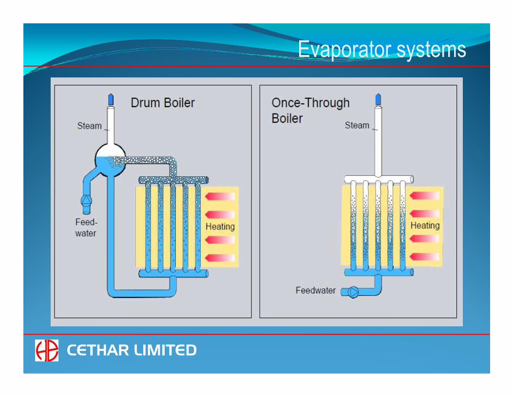
Evaporator systems
CETHAR LIMITED

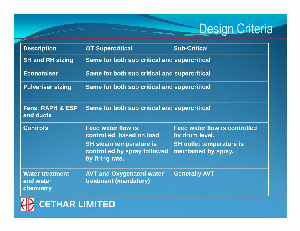
Design Criteria
Description OT Super critical Sub-Critical
Furnace sizing Decided by Fuel and Gas side parameters
Same
Evaporator Supercritical fluid;Variable evaporation end point; Superheated steam at evaporator outlet;
(Supported by BENSON
Water and Steam mixture;Fixed evaporation end point;Saturated steam at evaporator outlet
CETHAR LIMITED
Technology) Natural / controlled circulation
Drum Replaced by smaller Separators and collecting vessel. Required only during low loads (about 35-40%)
Required for water and steam separation at all loads
Start up and low load circulation system
Required.(Supported by BENSON Technology)
Not applicable
Design Criteria
Description OT Supercritical Sub-Critical
SH and RH sizing Same for both sub critical and sup ercritical
Economiser Same for both sub critical and supercriti cal
Pulveriser sizing Same for both sub critical and sup ercritical
Fans. RAPH & ESP and ducts
Same for both sub critical and supercritical
CETHAR LIMITED
and ducts
Controls Feed water flow is controlled based on loadSH steam temperature is controlled by spray followed by firing rate.
Feed water flow is controlled by drum level.SH outlet temperature is maintained by spray.
Water treatment and water chemistry
AVT and Oxygenated water treatment (mandatory)
Generally AVT

Furnace Design
FEGT = IDT - 50 K
FEGT = Furnace exit gas temperature
IDT = Initial deformation temperature of ash
CETHAR LIMITED
IDT = Initial deformation temperature of ash
Furnace design and size are decided by coal and ash quality

Evaporator wall design
� Heat absorption variation and resulting temperature difference at furnace wall outlet
Key Issues
� Boiling crisis like DNB and Dry out and associated wall temperatures
CETHAR LIMITED

Evaporator systems
CETHAR LIMITED

Steam temperature at furnace wall outlet
CETHAR LIMITED

Heat flux variation in furnace
CETHAR LIMITED

Sliding pressure operation
CETHAR LIMITED

Operating regimes
CETHAR LIMITED

Fluid Density
CETHAR LIMITED

Flow pattern
Flow pattern at different pressures:Supercritical Subcritical
Insignificant density differenceat Supercritical pressure results
CETHAR LIMITED
at Supercritical pressure resultsin single phase supercritical fluid. Consequently there is no DNB andDry Out which exist in sub-criticalpressure regime of operation.

Boiling Crisis
CETHAR LIMITED

Evaporator Designs
� High mass flux design (2000 to 2400 kg/ m2 s)
� Spiral wall arrangement with smooth tubes
� Medium mass flux design (1500 to 2000 kg/m2 s)
� Vertical wall arrangement with rifle tubes and orifices� Vertical wall arrangement with rifle tubes and orifices
� Low mass flux design (900 to 1000 kg/m2 s)
� Vertical wall arrangement with optimised multilead rifled tubes
CETHAR LIMITED

Furnace wall designs
CETHAR LIMITED

CETHAR’s 660 MW boiler
LTSH
HTSH HTRH
Screen Low mass flux design
Furnace with Vertical tubes
CETHAR LIMITED
Econ
LTRH
RSH
Optimised Multi Lead Rifled tubes for lower furnace (OMLR tubes)

Spiral wall arrangement
CETHAR LIMITED
Spiral wall construction reduces the number of eva porator wall tubes and thereby increases mass flux through the tubes.
This ensures a minimum water wall flow and protects water wall tubes.

Changes in mass flux
%16
12
8
4
.
.∆mmm ean
Change of mass flowin a tube with 25%increased heat input
%16
12
8
4
.
.∆mmm ean
Change of mass flowin a tube with 25%increased heat input
CETHAR LIMITED
600 800 1200 kg/m2s1000 1400 1800Mass flux (at full load)
4
0
-4
-8
-12
-16
Naturalcirculation
Once-through
600 800 1200 kg/m2s1000 1400 1800Mass flux (at full load)
4
0
-4
-8
-12
-16
Naturalcirculation
Once-through

Impact of flow characteristic on fluid temperatures
High mass fluxHigh mass flux Low mass fluxLow mass flux
100%
85%420°C
524°C100% 101%
420°C461°C
∆ = 104°C∆ = 41°C
High mass fluxHigh mass flux Low mass fluxLow mass flux
100%
85%420°C
524°C100% 101%
420°C461°C
∆ = 104°C∆ = 41°C
CETHAR LIMITED
Mass flux Mass fluxOutlettemperature
Outlettemperature
1308 // Tubesda 29.65 mm; di 16.65 mmMass flux 1805 kg/m²s
1298 // Tubesda 34.92 mm; di 21.91 mmMass flux 1050 kg/m²s
Mass flux Mass fluxOutlettemperature
Outlettemperature
1308 // Tubesda 29.65 mm; di 16.65 mmMass flux 1805 kg/m²s
1298 // Tubesda 34.92 mm; di 21.91 mmMass flux 1050 kg/m²s
Flow Features of a Water Wall Tube with 25% Excess Heat Input

Evaporator wall design
� Heat absorption variation and resulting temperature difference at furnace wall outlet
Key Issues
� Boiling crisis like DNB and Dry out and associated wall temperatures
CETHAR LIMITED

Rifle tube
CETHAR LIMITED

Smooth Vs Rifle tubes
CETHAR LIMITED

Optimised Multilead Rifled Tube
CETHAR LIMITED

Comparison of various designs
Parameter High mass flux
Spiral wall
Medium mass flux, vertical wall
Low mass flux
Vertical wall
Flow Characteristic
Once through characteristic Once through characteristic
Natural circulation flow characteristic
Mass flux High
(around 2000 kg/m2-s
at full load or above)
Medium to High (around 1500 to 2000 kg/m2-s at full load)
Low
(around 1000 kg/m2-s
at full load)
Furnace wall tube Smooth tubes Rifled tubes with orifices
Optimized Multi Lead Rifled Tubes (OMLR)
Pressure drop in
furnace wall
Higher Higher Lower
Good savings in BFP power consumption
Furnace wall attachments & buck stays
Complex
Typical increase in weight for a 660 MW boiler is approx. 400 t
Simple,
Self supporting
Simple
Self supporting
Manufacturing &
Construction
Difficult compared to vertical design Easier Easier
Maintenance Difficult due to presence of vertical supporting straps
Easier Easier
CETHAR LIMITED

Waterwall flow
WATER WALL FLOW
50
60
70
80
90
100
FLO
W %
CETHAR LIMITED
0
10
20
30
40
50
0 10 20 30 40 50 60 70 80 90 100
LOAD %
FLO
W %
WW FLOW

Start up and low load circulation system
CETHAR LIMITED

Materials
SectionSection Sub criticalSub critical Super criticalSuper critical
EconomiserEconomiser SA 210 Gr A1 / CSA 210 Gr A1 / C SA 210 Gr A1 / CSA 210 Gr A1 / C
Water wallWater wall SA 210 Gr CSA 210 Gr C SA 213 T11 / T12/T22 SA 213 T11 / T12/T22
SA 213 T11, T22, T91, SA 213 T11, T22, T91, T92, T92,
CETHAR LIMITED
Super heaters and Super heaters and re heaterre heater
SA 213 T11, T22,T91 and SA 213 T11, T22,T91 and TP 347 HTP 347 H
SA 213 T11, T22, T91, SA 213 T11, T22, T91, T92, T92, Super 304HSuper 304H, and TP 347 H, and TP 347 H
Headers and Headers and pipingpiping
SA 106 Gr B, Gr C, P11, SA 106 Gr B, Gr C, P11, P22 and P91P22 and P91
SA 106 SA 106 GrGr B, B, GrGr C, P11, C, P11, P22, P22, 302 302 GrGr C C and P91, and P91, P92P92

Control concepts specific to Once through boilers
� Feed water flow control:� Feed water flow is controlled by drum level in drum type boilers. In
once trough boiler, feed flow depends directly on the load.
� SH steam temperature control� In drum type boiler, SH outlet temperature is maintained by spray.
In once through boiler, SH steam temperature is controlled by spray followed by firing rate.
CETHAR LIMITED
� Water collecting vessel level control� Swell during start up is discharged by two quick acting control
valves into a flash tank.
� During low load operation, water level is maintained over a range by a flow control valve located downstream of circulating pump.

Water treatment
� Stringent water quality requirements. Water quality requirements are
to be strictly adhered to as there is no blow down from drum
� Oxygenated water treatment is used
� Oxygen is injected to reduce the formation of magnetite layer
(Fe3O4) and form more of hematite layer (Fe2O3) which will reduce
the deposits and the pressure drop
CETHAR LIMITED
the deposits and the pressure drop
� To achieve this, oxygen in feed water is to be maintained within 0.03
to 0.15 mg/L and the conductivity of feed water at 25 deg C
downstream of cation exchanger is to be maintained less than 0.15
micro Siemens/cm
� During Start up : All Volatile Treatment (AVT)
� During Normal Operation : Oxygenated water treatment

Benson experience
167 m
CETHAR LIMITED
Aghios Dimitrios Power Plant, Greece286 kg/s - lignite242 bar / 540°C / 540°C
Lippendorf Power Plant, Germany672 kg/s - lignite285 bar / 554°C / 583°C
Hekinan Power Plant, Japan639 kg/s - imported coal255 bar / 543°C / 569°C
Hemweg Power Plant, Netherlands530 kg/s - imported coal261 bar / 540°C / 540°C
NordjyllandsvaerketPower Plant, Denmark270 kg/s - imported coal310 bar / 582°C / 580°C
Ibbenbüren Power Plant, Germany600 kg/s - anthracite220 bar / 530°C / 530°C
Pressures are maximum allowable working pressures

Low mass flux design references
(PC fired boilers)
CETHAR LIMITED
Long view has been commissioned and has reached ful l load in June 2011.
No thermo hydraulic problem

Low mass flux reference
CFBC boilers
CETHAR LIMITED

Low mass flux references
Anthracite fired boilers
CETHAR LIMITED

Why CETHAR need to be qualified?Experience of Riley in the design, supply and commi ssioning of 1290 t/hr constant pressure supercritical boiler
Availability of long term collaboration agreement w ith Siemens for sliding pressure supercritical evaporator system at the han ds of Riley and CETHAR
Royalty payment obligations of CETHAR ensures the s upport of Collaborators for design review, support for Erecti on & Commissioning and trouble shooting.
CETHAR LIMITED
and trouble shooting.
Experience of Riley in the design, supply and commi ssioning of sub critical boilers in excess of 500 MW and with var ied fuels
Readily available manufacturing infrastructure for boilers with an annual capacity of 8000 MW
Availability of qualified and experienced world cla ss human resource

Why CETHAR need to be qualified?
25 years presence in boiler industry
CETHAR’s self belief on technology development
Role played by CETHAR in the introduction of fluid bed boilers
Computerisation and centralising the knowledge for consistent
CETHAR LIMITED
Computerisation and centralising the knowledge for consistent performance in design , manufacture and constructio n of power plants.
CETHAR’s willingness to offer high level transparen cy in project execution
Substantial reduction in boiler price & delivery ti me.

CETHAR’S Request
� Inclusion of yet another route for supercritical
steam generator bidders:
Indian Boiler manufacturer with already established manufacturing
facility for an annual capacity of at least 5000 MW and having
technology through a collaborator who has already d esigned and
CETHAR LIMITED
technology through a collaborator who has already d esigned and
commissioned at least one number of coal fired con stant pressure
supercritical steam generator which is in successfu l operation for a
period of not less than one (1) year as on the date of bid opening. The
collaborator should also have a valid collaboration for variable
pressure evaporator from a technology Owner and a 5 00 MW coal fired
sub critical steam generator in operation.

THANK YOU
CETHAR LIMITED
Related Documents