1 Physics 7B - AB Lecture 2 April 10 Recap + examples Steady-State Energy Density Model Applied to Fluid Circuit & Electrical Circuit Lecture slides available at http://physics.ucdavis.edu/phys ics7

1 Physics 7B - AB Lecture 2 April 10 Recap + examples Steady-State Energy Density Model Applied to Fluid Circuit & Electrical Circuit Lecture slides available.
Dec 16, 2015
Welcome message from author
This document is posted to help you gain knowledge. Please leave a comment to let me know what you think about it! Share it to your friends and learn new things together.
Transcript

1
Physics 7B - ABLecture 2
April 10Recap + examples
Steady-State Energy Density ModelApplied to
Fluid Circuit & Electrical Circuit
Lecture slides available athttp://physics.ucdavis.edu/physics7

2
Course Websitehttp://physics.ucdavis.edu/physics7
Click on Physics 7B-A/B
Next weekLecturer 3Dr. Kevin Klapstein
April 16
My office hr is cancelled.
Today Quiz 1!
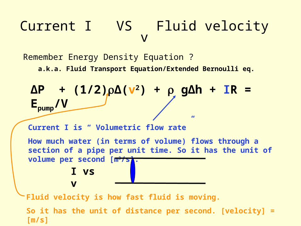
Current I VS Fluid velocity v
Remember Energy Density Equation ?a.k.a. Fluid Transport Equation/Extended Bernoulli eq.
∆P + (1/2)∆(v2) + g∆h + IR = Epump/V
Current I is “ Volumetric flow rate”
How much water (in terms of volume) flows through a section of a pipe per unit time. So it has the unit of volume per second [m3/s].
Fluid velocity is how fast fluid is moving.
So it has the unit of distance per second. [velocity] = [m/s]
I vs v
4
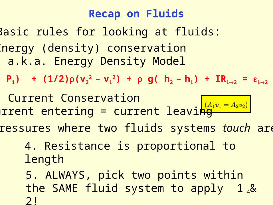
Recap on Fluids
Basic rules for looking at fluids:
1. Energy (density) conservation a.k.a. Energy Density Model
(P2– P1) + (1/2)(v22 – v1
2) + g( h2 – h1) + IR12 = 12
2. Current ConservationCurrent entering = current leaving
3. Pressures where two fluids systems touch are equal
4. Resistance is proportional to length
5. ALWAYS, pick two points within the SAME fluid system to apply 1 & 2!
5
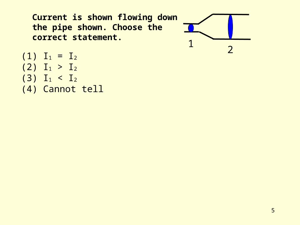
Current is shown flowing down the pipe shown. Choose the correct statement.
12
(1) I1 = I2(2) I1 > I2(3) I1 < I2(4) Cannot tell

6
Current is shown flowing down the pipe shown. Choose the correct statement.
12
(1) I1 = I2(2) I1 > I2(3) I1 < I2(4) Cannot tell

7
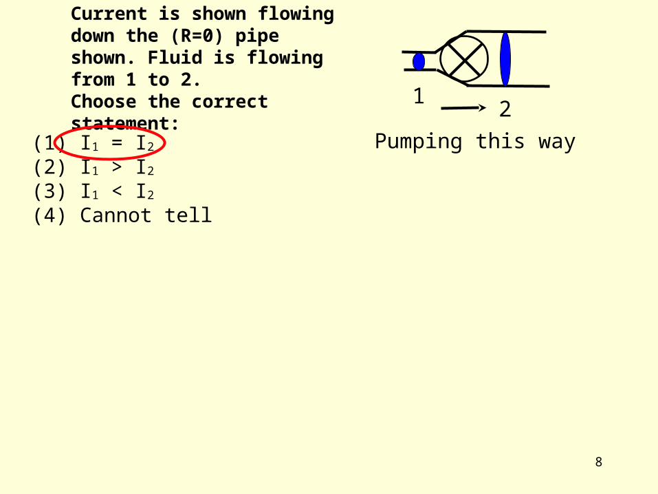
Current is shown flowing down the (R=0) pipe shown. Fluid is flowing from 1 to 2.Choose the correct statement: 1
2
(1) I1 = I2(2) I1 > I2(3) I1 < I2(4) Cannot tell
Pumping this way
8
Current is shown flowing down the (R=0) pipe shown. Fluid is flowing from 1 to 2.Choose the correct statement: 1
2
(1) I1 = I2(2) I1 > I2(3) I1 < I2(4) Cannot tell
Pumping this way

9
Current is shown flowing down the pipe shown. Choose the correct statement.
12(1) v1 = v2
(2) v1 > v2
(3) v1 < v2
(4) Cannot tell

10
Current is shown flowing down the pipe shown. Choose the correct statement.
12(1) v1 = v2
(2) v1 > v2
(3) v1 < v2
(4) Cannot tell
11
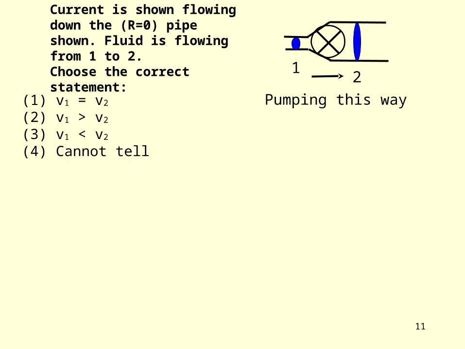
Current is shown flowing down the (R=0) pipe shown. Fluid is flowing from 1 to 2.Choose the correct statement: 1
2Pumping this way(1) v1 = v2
(2) v1 > v2
(3) v1 < v2
(4) Cannot tell
12
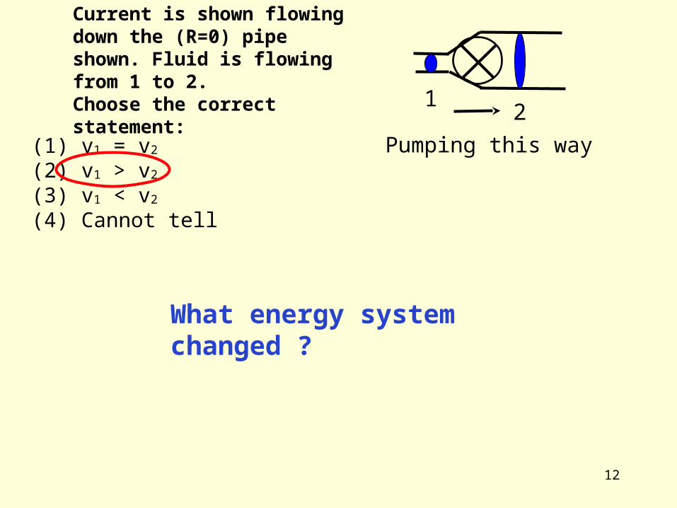
Current is shown flowing down the (R=0) pipe shown. Fluid is flowing from 1 to 2.Choose the correct statement: 1
2Pumping this way(1) v1 = v2
(2) v1 > v2
(3) v1 < v2
(4) Cannot tell
What energy system changed ?
13
The following shows a pipe without dissipation (R=0) with a pump attached. On which side is the pressure greater?
1 2(1) Side 1(2) Side 2(3) Not enough information
Pumping this way
14
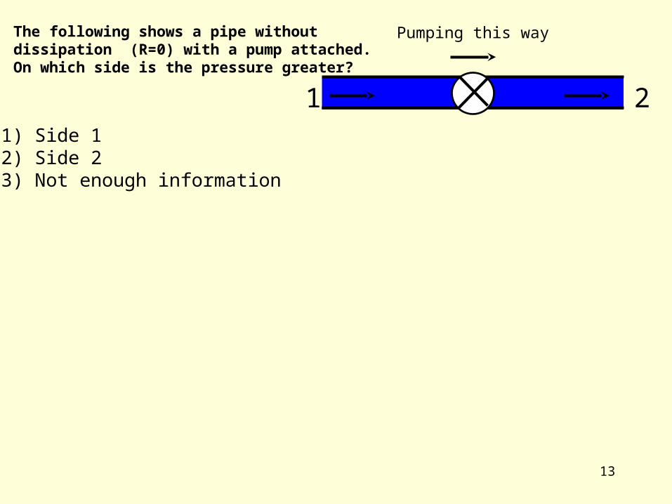
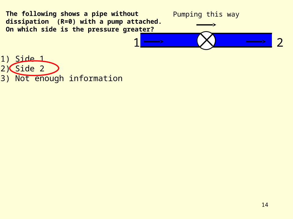
The following shows a pipe without dissipation (R=0) with a pump attached. On which side is the pressure greater?
1 2(1) Side 1(2) Side 2(3) Not enough information
Pumping this way
15
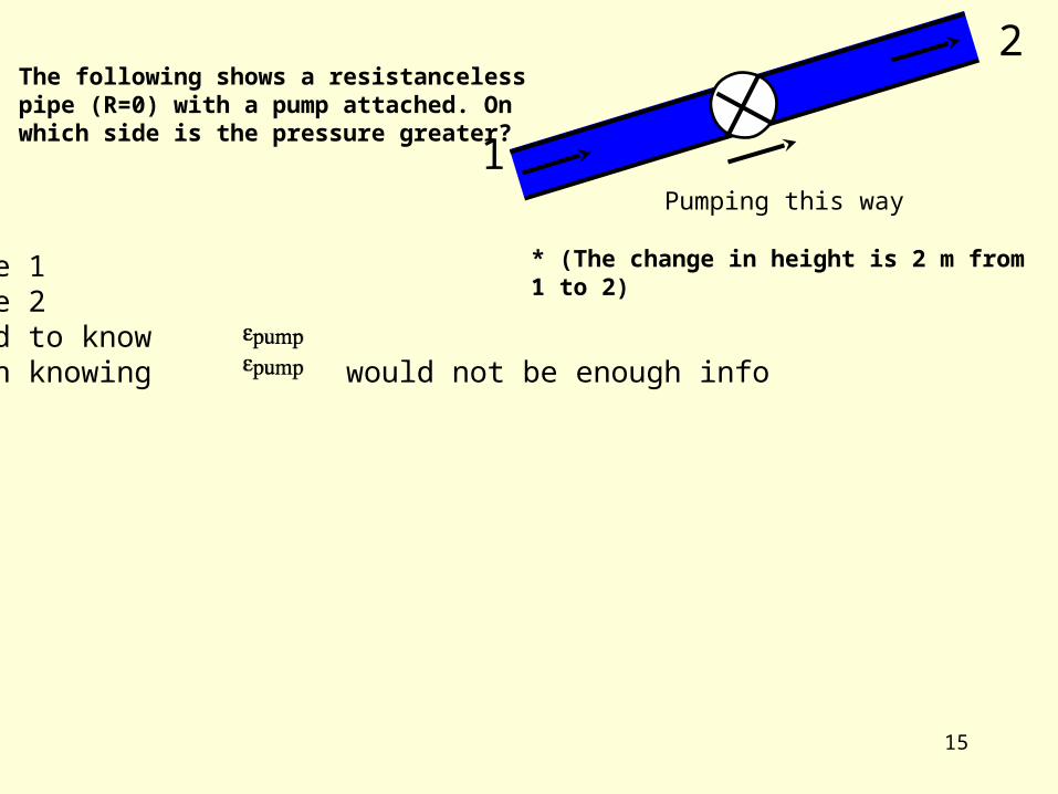
The following shows a resistanceless pipe (R=0) with a pump attached. On which side is the pressure greater?
1
2
(1) Side 1(2) Side 2(3) Need to know (4) Even knowing would not be enough info
Pumping this way
* (The change in height is 2 m from 1 to 2)

16
The following shows a resistanceless pipe (R=0) with a pump attached. On which side is the pressure greater?
1
2
(1) Side 1(2) Side 2(3) Need to know (4) Even knowing would not be enough info
Pumping this way
* (The change in height is 2 m from 1 to 2)

17
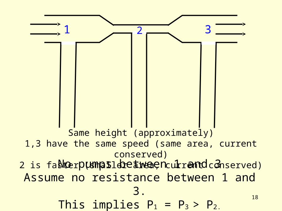
1 32
How does P1, P2 , P3
compare?
Assume no dissipation, i.e., R = 0.
18
Same height (approximately)1,3 have the same speed (same area, current conserved)
2 is faster (smaller area, current conserved)
1 32
No pumps between 1 and 3Assume no resistance between 1 and 3.
This implies P1 = P3 > P2.
19
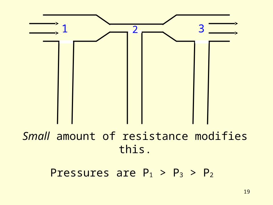
1 32
Small amount of resistance modifies this.
Pressures are P1 > P3 > P2

20
1 32
Large amount of resistance modifies this.
Pressures are P1 > P2 > P3
21
ElectricalElectrical circuits circuits
Recap and Examples on

22
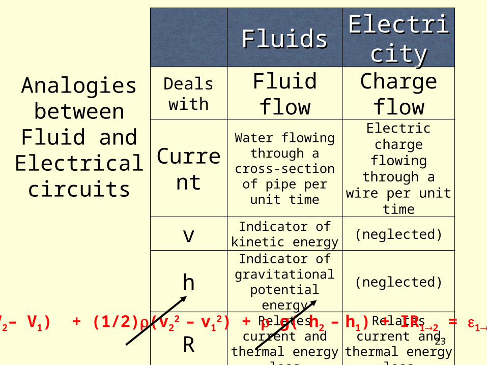
Analogies between Fluid and Electrical circuits
FluidsFluids ElectricityElectricityDeals with Fluid flow Charge flow
CurrentWater flowing
through a cross-section of pipe per
unit time
Electric charge flowing through a wire per unit time
v Indicator of kinetic energy
(neglected)
hIndicator of
gravitational potential energy
(neglected)
R Relates current and thermal energy loss
Relates current and thermal energy loss
Energy stored /unit volume
or chargePressure Voltage
(P2– P1) + (1/2)(v22 – v1
2) + g( h2 – h1) + IR12 = 12
23
Analogies between Fluid and Electrical circuits
FluidsFluids ElectricityElectricityDeals with Fluid flow Charge flow
CurrentWater flowing
through a cross-section of pipe per
unit time
Electric charge flowing through a wire per unit time
v Indicator of kinetic energy
(neglected)
hIndicator of
gravitational potential energy
(neglected)
R Relates current and thermal energy loss
Relates current and thermal energy loss
Energy stored /unit volume
or chargePressure Voltage
(V2– V1) + (1/2)(v22 – v1
2) + g( h2 – h1) + IR12 = 12

24
Analogies between Fluid and Electrical circuits
FluidsFluids ElectricityElectricityDeals with Fluid flow Charge flow
CurrentWater flowing
through a cross-section of pipe per
unit time
Electric charge flowing through a wire per unit time
v Indicator of kinetic energy
(neglected)
hIndicator of
gravitational potential energy
(neglected)
R Relates current and thermal energy loss
Relates current and thermal energy loss
Energy stored /unit volume
or chargePressure Voltage
Energy Density Equationa.k.a. transport equation
(V2– V1) + IR12 = 12
Or ∆V = – IR
25
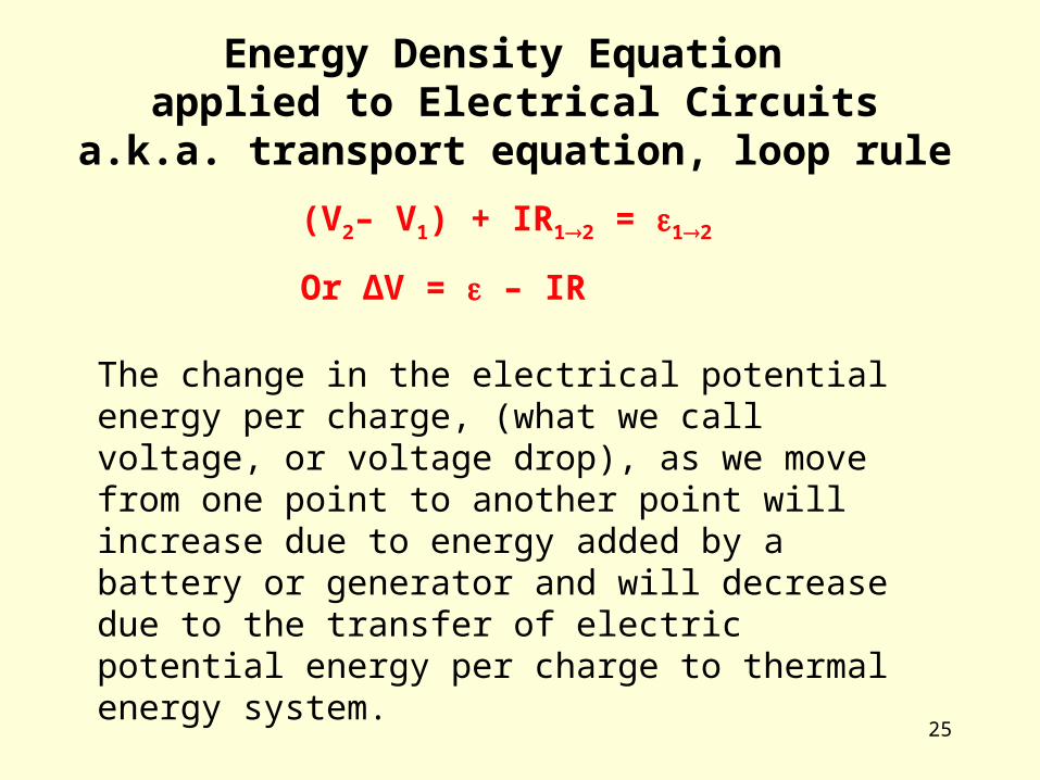
Energy Density Equation applied to Electrical Circuits
a.k.a. transport equation, loop rule
(V2– V1) + IR12 = 12
Or ∆V = – IR
The change in the electrical potential energy per charge, (what we call voltage, or voltage drop), as we move from one point to another point will increase due to energy added by a battery or generator and will decrease due to the transfer of electric potential energy per charge to thermal energy system.
26
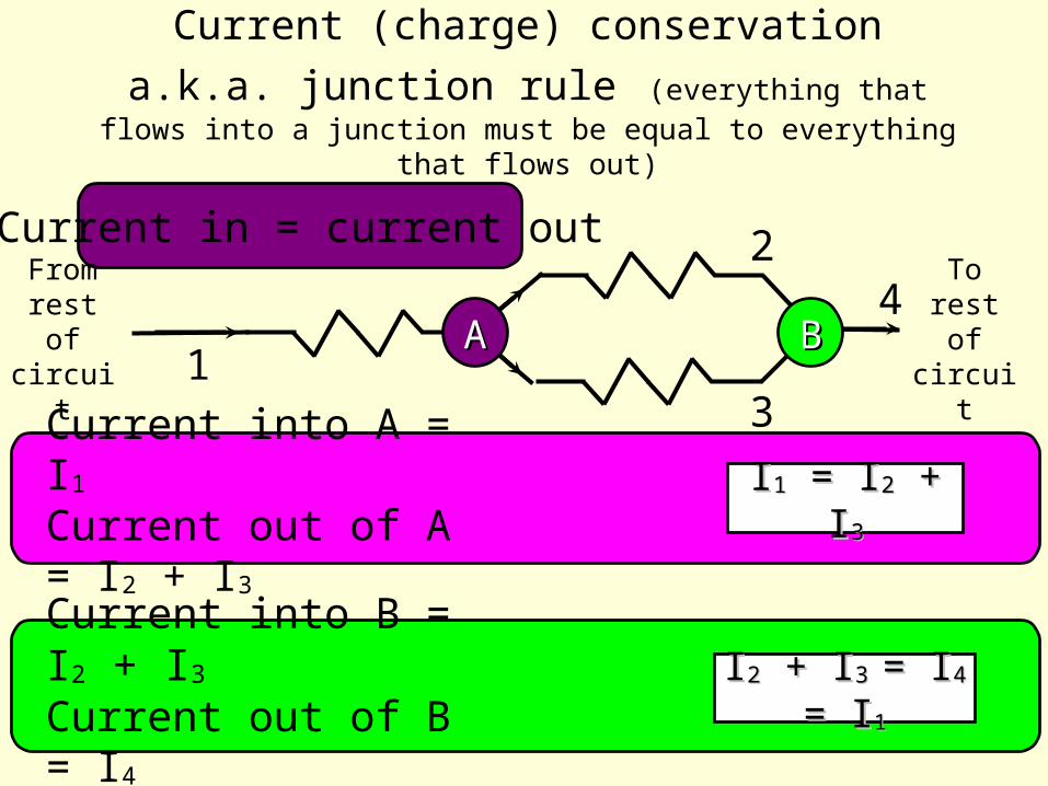
Current in = current out
From rest of circuit
To rest of
circuit1
2
3
4AA BB
Current into A = I1Current out of A = I2 + I3
Current into B = I2 + I3Current out of B = I4
II11 = I = I22 + I + I33
II22 + I + I3 3 = I= I44 = = II11
Current (charge) conservation
a.k.a. junction rule (everything that flows into a junction must be equal to everything that flows out)
27
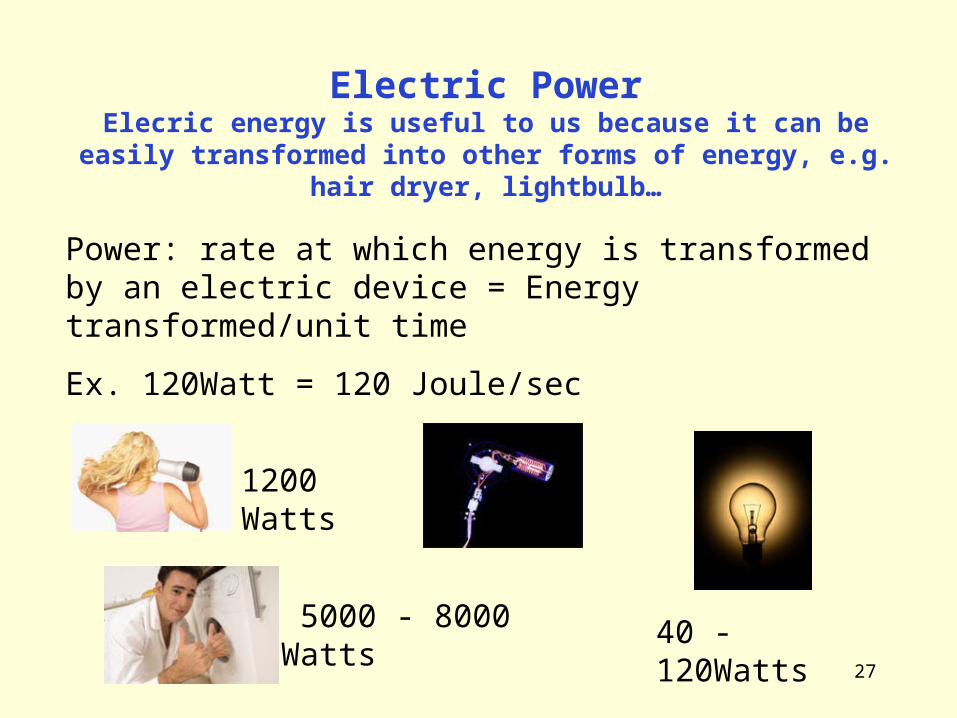
Electric PowerElecric energy is useful to us because it can be easily
transformed into other forms of energy, e.g. hair dryer, lightbulb…
Power: rate at which energy is transformed by an electric device = Energy transformed/unit time
Ex. 120Watt = 120 Joule/sec
1200 Watts
40 - 120Watts 5000 - 8000 Watts
28
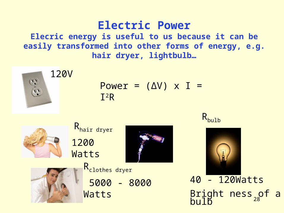
Electric PowerElecric energy is useful to us because it can be easily
transformed into other forms of energy, e.g. hair dryer, lightbulb…
Power = (∆V) x I = I2R
1200 Watts
40 - 120Watts
Bright ness of a bulb
5000 - 8000 Watts
Rhair dryer
Rclothes dryer
Rbulb
120V
29
1. Bulbs 1 and 2 are connected with a battery as shown to the right. The bulbs have different resistances (R 1 ? R2). Which
statement must ?be true
)A , The two bulbs have the same voltage difference? , V across them and that ? V is half the
battery voltage . B) The two bulbs are equally bright . )C The two bulbs and the battery all have the same
current through them . )D .All of the above must be true )E N one of the above must be true .
21
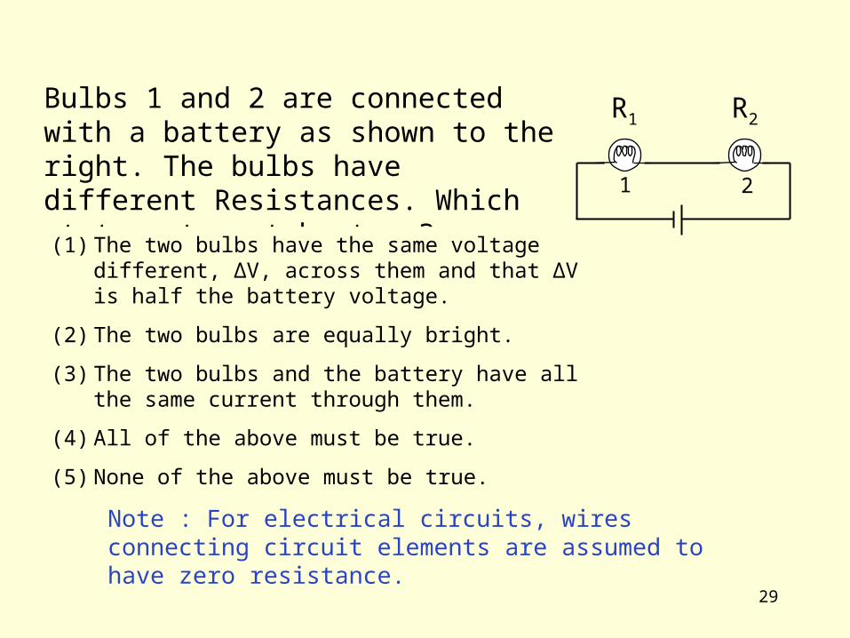
R1 R2Bulbs 1 and 2 are connected with a battery as shown to the right. The bulbs have different Resistances. Which statement must be true?
(1) The two bulbs have the same voltage different, ∆V, across them and that ∆V is half the battery voltage.
(2) The two bulbs are equally bright.
(3) The two bulbs and the battery have all the same current through them.
(4) All of the above must be true.
(5) None of the above must be true.
Note : For electrical circuits, wires connecting circuit elements are assumed to have zero resistance.
30
1. Bulbs 1 and 2 are connected with a battery as shown to the right. The bulbs have different resistances (R 1 ? R2). Which
statement must ?be true
)A , The two bulbs have the same voltage difference? , V across them and that ? V is half the
battery voltage . B) The two bulbs are equally bright . )C The two bulbs and the battery all have the same
current through them . )D .All of the above must be true )E N one of the above must be true .
21
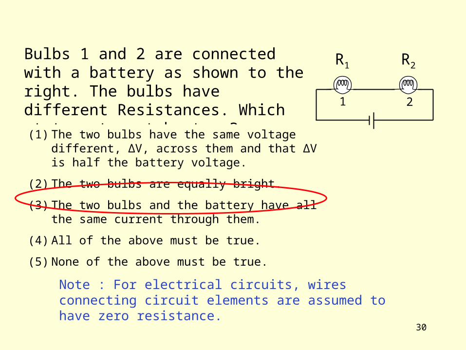
R1 R2Bulbs 1 and 2 are connected with a battery as shown to the right. The bulbs have different Resistances. Which statement must be true?
(1) The two bulbs have the same voltage different, ∆V, across them and that ∆V is half the battery voltage.
(2) The two bulbs are equally bright.
(3) The two bulbs and the battery have all the same current through them.
(4) All of the above must be true.
(5) None of the above must be true.
Note : For electrical circuits, wires connecting circuit elements are assumed to have zero resistance.
31
6. If the four light bulbs in the figure are identical and the batteries are identical, which circuit puts out more light? (Note: brightness depends on the power used so it is good enough to just determine which bulbs have the largest current?)
A) 1 emi ts more light. B) The two emit the same amount
of light. C) 2 emits more light. D) True E) False
1 2
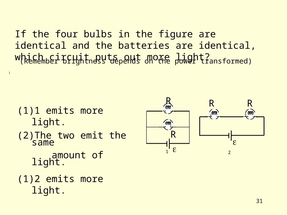
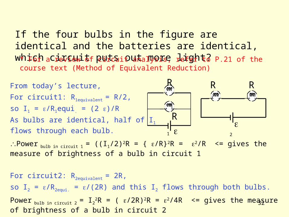
If the four bulbs in the figure are identical and the batteries are identical, which circuit puts out more light?
(Remember brightness depends on the power transformed)
(1) 1 emits more light.
(2) The two emit the same amount of light.
(1) 2 emits more light.
R
R
R R
32
6. If the four light bulbs in the figure are identical and the batteries are identical, which circuit puts out more light? (Note: brightness depends on the power used so it is good enough to just determine which bulbs have the largest current?)
A) 1 emi ts more light. B) The two emit the same amount
of light. C) 2 emits more light. D) True E) False
1 2
(Remember brightness depends on the power transformed)
From today’s lecture,
For circuit1: R1equivalent = R/2,
so I1 = /R1equi. = (2 )/R
As bulbs are identical, half of I1
flows through each bulb.
Power bulb in circuit 1 = ((I1/2)2R = { /R}2R = 2/R <= gives the measure of brightness of a bulb in circuit 1
For circuit2: R2equivalent = 2R,
so I2 = /R2equi. = /(2R) and this I2 flows through both bulbs.
Power bulb in circuit 2 = I22R = ( /2R)2R = 2/4R <= gives the measure of brightness of a bulb in circuit 2
If the four bulbs in the figure are identical and the batteries are identical, which circuit puts out more light?
R
R
R R
* For a review of circuit analysis, refer to P.21 of the course text (Method of Equivalent Reduction)

33
6. If the four light bulbs in the figure are identical and the batteries are identical, which circuit puts out more light? (Note: brightness depends on the power used so it is good enough to just determine which bulbs have the largest current?)
A) 1 emi ts more light. B) The two emit the same amount
of light. C) 2 emits more light. D) True E) False
1 2
If the four bulbs in the figure are identical and the batteries are identical, which circuit puts out more light?
(Remember brightness depends on the power transformed)
(1) 1 emits more light.
(2) The two emit the same amount of light.
(1) 2 emits more light.

34
6. If the four light bulbs in the figure are identical and the batteries are identical, which circuit puts out more light? (Note: brightness depends on the power used so it is good enough to just determine which bulbs have the largest current?)
A) 1 emi ts more light. B) The two emit the same amount
of light. C) 2 emits more light. D) True E) False
1 2
If the two bulbs in the circuit 1 are NOT identical,
which bulb puts out more light?
(1) Bulb A emits more light.
(2) The two emit the same amount of light.
(1) Bulb B emits more light.
RA
RB
(Remember brightness depends on the power transformed)
RA > RB
Example Solve this for = 6V, RA= 3 Ohm, RB= 1 Ohm

35
6. If the four light bulbs in the figure are identical and the batteries are identical, which circuit puts out more light? (Note: brightness depends on the power used so it is good enough to just determine which bulbs have the largest current?)
A) 1 emi ts more light. B) The two emit the same amount
of light. C) 2 emits more light. D) True E) False
1 2
If the two bulbs in the circuit 1 are NOT identical,
which bulb puts out more light?
(1) Bulb A emits more light.
(2) The two emit the same amount of light.
(1) Bulb B emits more light.
RA
RB
(Remember brightness depends on the power transformed)
RA > RB
Example Solve this for = 6V, RA= 3 Ohm, RB= 1 Ohm
You should find, IA = 2A, IB = 6A, and
PA = 12Watts, PB = 36Watts
36
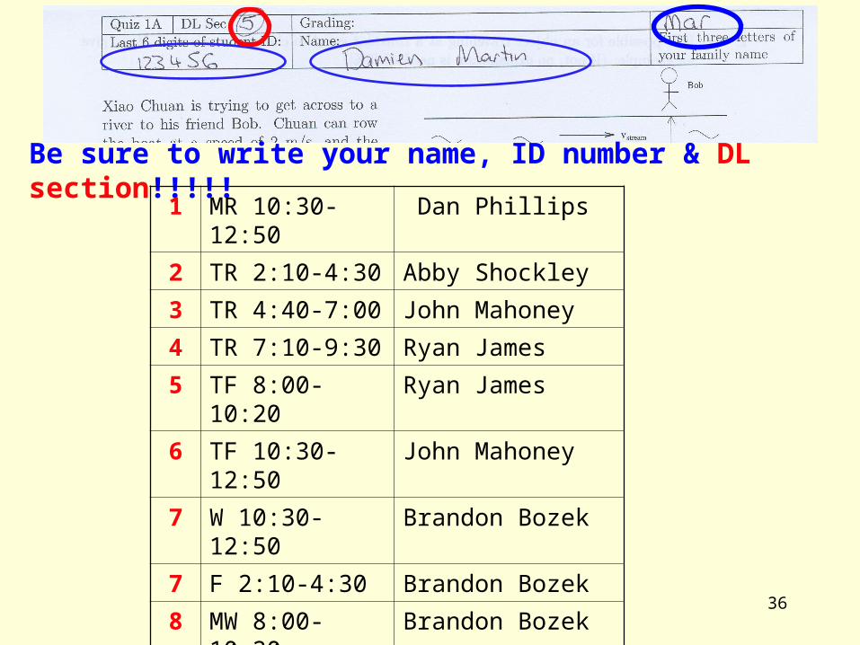
Be sure to write your name, ID number & DL section!!!!!1 MR 10:30-12:50 Dan Phillips
2 TR 2:10-4:30 Abby Shockley
3 TR 4:40-7:00 John Mahoney
4 TR 7:10-9:30 Ryan James
5 TF 8:00-10:20 Ryan James
6 TF 10:30-12:50 John Mahoney
7 W 10:30-12:50 Brandon Bozek
7 F 2:10-4:30 Brandon Bozek
8 MW 8:00-10:20 Brandon Bozek
9 MW 2:10-4:30 Chris Miller
10 MW 4:40-7:00 Marshall Van Zijll
11 MW 7:10-9:30 Marshall Van Zijll
Related Documents