1 Motion Sensors lacement, velocity and accelera

1 Motion Sensors Displacement, velocity and acceleration.
Jan 01, 2016
Welcome message from author
This document is posted to help you gain knowledge. Please leave a comment to let me know what you think about it! Share it to your friends and learn new things together.
Transcript

1
Motion SensorsDisplacement, velocity and acceleration

2
Dimensional measurement
• One complete revolution = 0.5 mm (usually)• With 50 divisions, each division movement
corresponds to 0.01 mm• If user can control every one-fifth of a
division, a resolution of 0.002 mm is possible
MicrometersVernier caliper
3
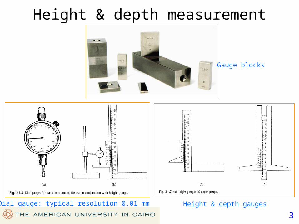
Height & depth measurement
Gauge blocks
Dial gauge: typical resolution 0.01 mm Height & depth gauges

4
Types: wire-wound, carbon-film and plastic-film (according to resistance element)
Linear potentiometer Rotary potentiometer (a) circular; (b) helical
Resistive potentiometer

5
Primary Secondary
Linear Variable Differential Transformer (LVDT)
• Inductive displacement sensor.• Transformer with 1 primary & 2 secondary coils, connected in series opposition• Output voltage (difference between induced voltages) is proportional to core
displacement• Zero reading when core is centered
Rotary differential transformer

6
Eddy current sensor• Inductive displacement sensor.• Coil is excited at high frequency (typically 1 MHz)• This induces eddy current in the target• Eddy current alters the inductance of the probe coil• This change can be translated into a voltage proportional to the air gap

7
Piezoelectric transducers
• A piezoelectric material generates charge when deformed• Induced charge leaks away with time• Piezoelectric transducers are not suitable for static or slowly-varying dispalcements
8
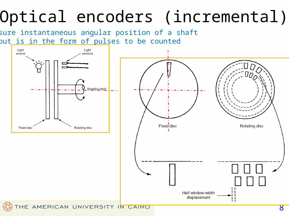
Optical encoders (incremental)• Measure instantaneous angular position of a shaft• Output is in the form of pulses to be counted
9
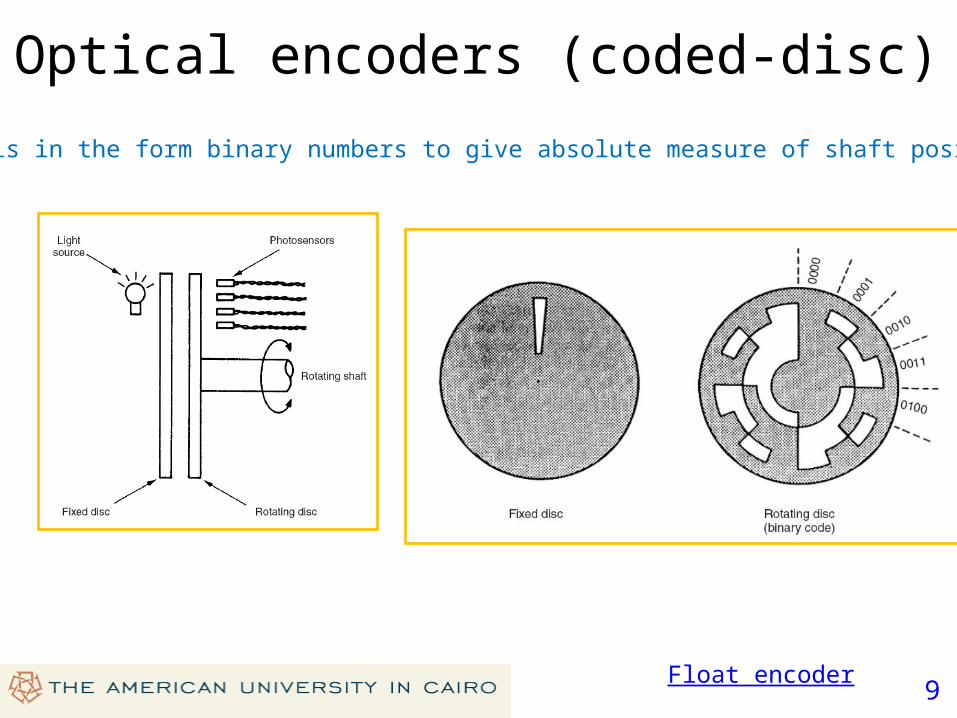
Optical encoders (coded-disc)
• Output is in the form binary numbers to give absolute measure of shaft position
Float encoder
10
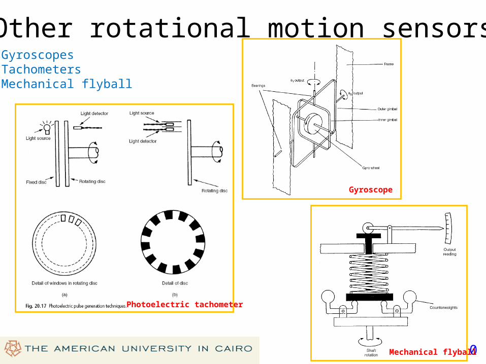
Other rotational motion sensors• Gyroscopes• Tachometers • Mechanical flyball
Gyroscope
Photoelectric tachometer
Mechanical flyball
11
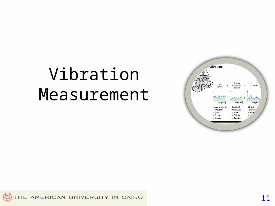
Vibration Measurement
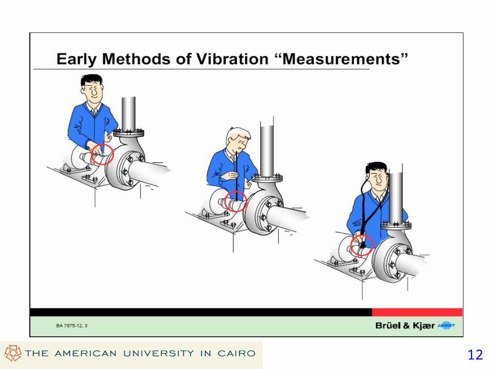
12

13

14
15

16
Energy Harvesting
Source: J.K. Ward and S. Behrens, “Adaptive learning algorithms for vibration energy harvesting”, Smart Materials & Structures 17 (2008) 035025 1-9.

17
Vibration-based Energy Harvesting
Source: B.P. Mann and N.D.Sims, “Energy harvesting from the nonlinear oscillations of magentic levitation”, Journal of Sound and Vibration (2008) in press.

18
19
Related Documents