1 Ch. 6 Displacement, Velocity and Acceleration Sensors

Welcome message from author
This document is posted to help you gain knowledge. Please leave a comment to let me know what you think about it! Share it to your friends and learn new things together.
Transcript
1
Ch. 6
Displacement, Velocity and Acceleration Sensors
2
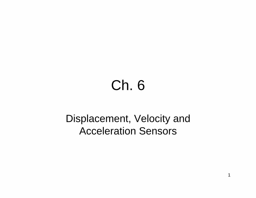
All types of Displacement Sensors
• Resistive Displacement Sensors• Inductive Displacement Sensors• Capacitive Sensors—Displacement• Piezoelectric Transducers and Sensors• Time-of-Flight Ultrasonic Displacement Sensors• Magnetic Displacement Sensors• Laser Interferometer Displacement Sensors• Optical Encoder Displacement Sensors

3
Resistive Displacement Sensors
• Commonly termed potentiometers or “pots”.

4
Resistive Displacement Sensors
• An electrically conductive wiper that slides against a fixed resistive element.
• To measure displacement, a potentiometer is typically wired in a “voltage divider” configuration.
• The circuit’s output, a function of the wiper’s position, is an analog voltage available for direct use or digitization.
5
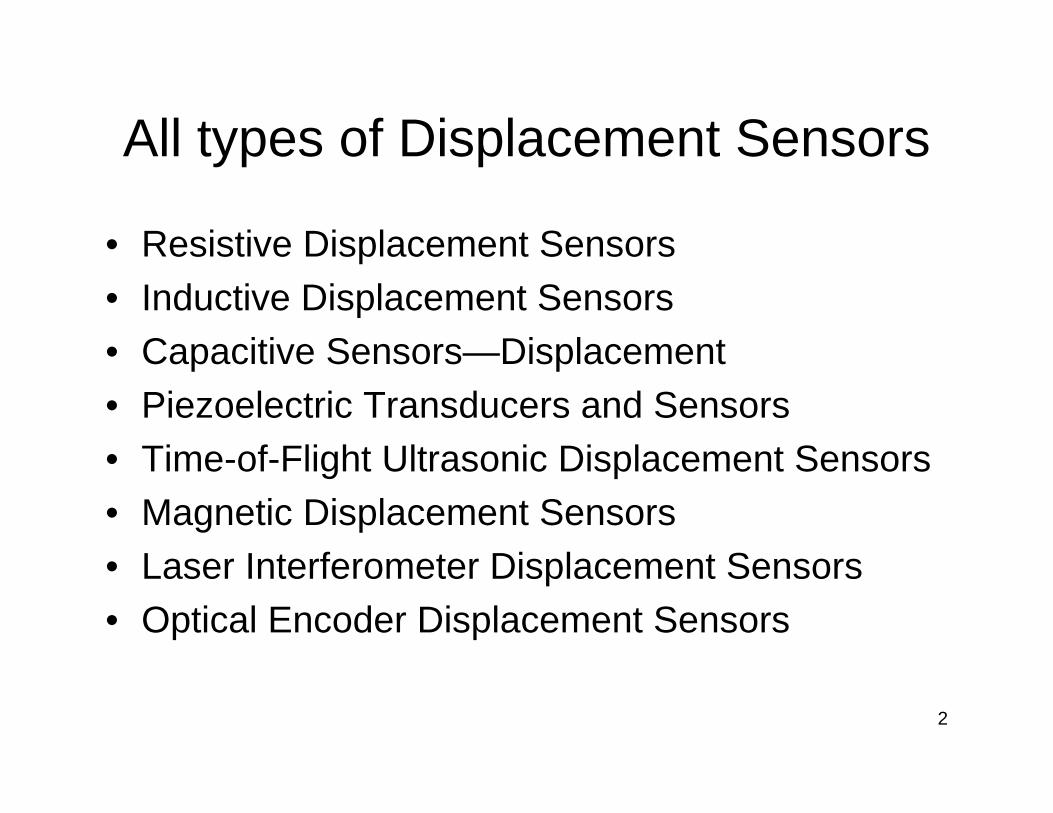
Resistive Displacement Sensors
• (a) A potentiometer is used as a variable voltage divider. RP is the total resistance of the potentiometer, RL is the load resistance, Vr is the reference or supply voltage, and V0 is the output voltage. (b) An ideal linear output function. xP is the maximum position of the wiper.

6
Resistive Displacement Sensors
Passive
WearProven technology
Inertial loadingHigh-amplitude output signal
Frictional loadingLow cost
Limited bandwidthEasy to use
DisadvantagesAdvantages
Fundamental Potentiometer Characteristics
7
Resistive Displacement Sensors
• Precision Potentiometers are available in rotary, linear-motion, and string potentiometer forms.
• Resistive element can be classified as either wirewound, or nonwirewound.
8
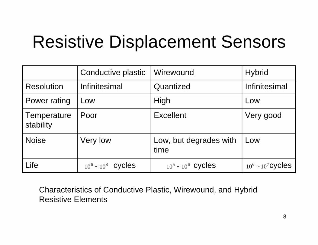
Resistive Displacement Sensors
cyclescyclescyclesLife
LowLow, but degrades with time
Very lowNoise
Very goodExcellentPoorTemperature stability
LowHighLowPower rating
InfinitesimalQuantizedInfinitesimalResolution
HybridWirewoundConductive plastic
86 10~10 65 10~10 76 10~10
Characteristics of Conductive Plastic, Wirewound, and Hybrid Resistive Elements
9
Resistive Displacement Sensors—Electrical Characteristics
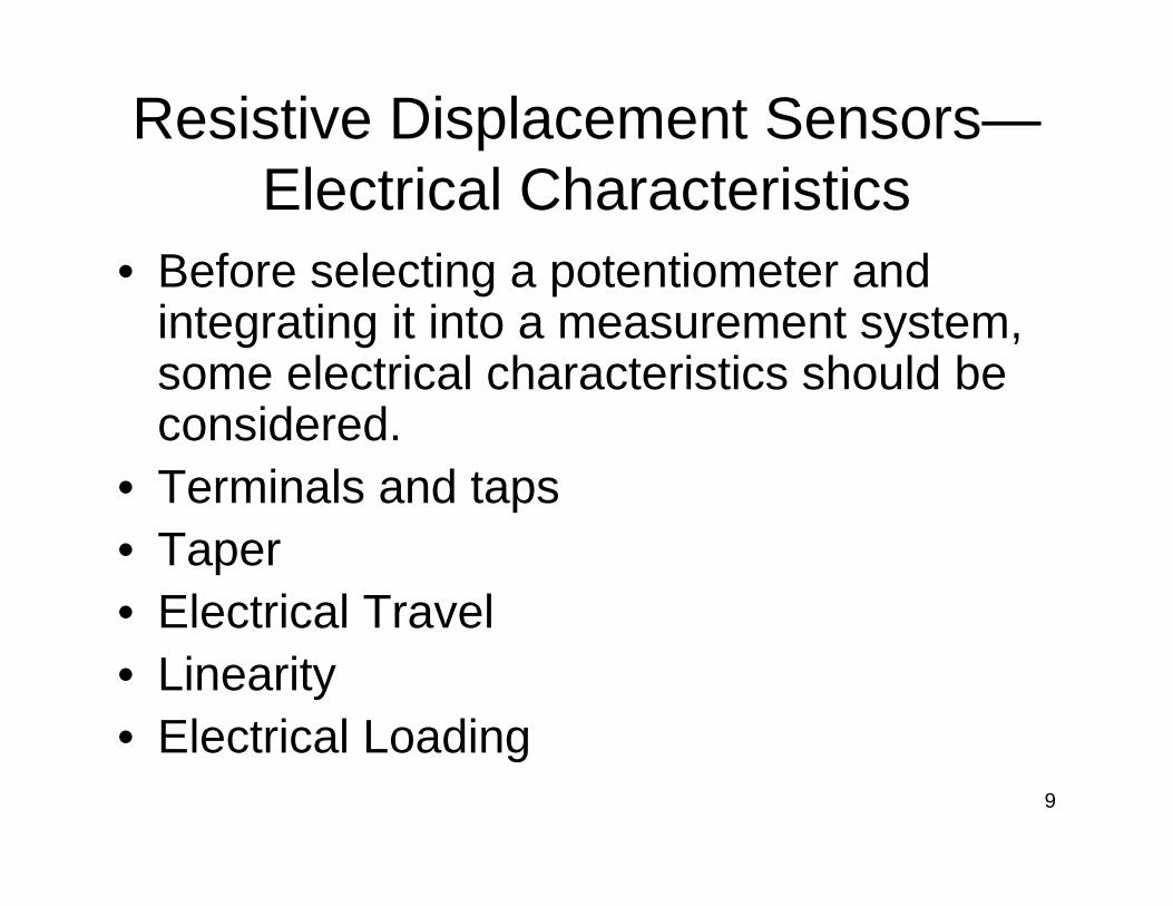
• Before selecting a potentiometer and integrating it into a measurement system, some electrical characteristics should be considered.
• Terminals and taps• Taper• Electrical Travel• Linearity• Electrical Loading

10
Resistive Displacement Sensors—Electrical Characteristics
• Independent linearity is the maximum amount by which the actual output function deviates from a line of best fit.

11
Resistive Displacement Sensors—Mechanical Characteristics
• Mechanical characteristics may also influence measurement quality and system reliability.
• Mechanical Loading• Mechanical Travel• Operating Temperature• Vibration, Shock, and Acceleration• Speed• Contamination and Seals• Misalignment• Lifetime of potentiometer
12
Resistive Displacement Sensors—Mechanical Mounting Methods
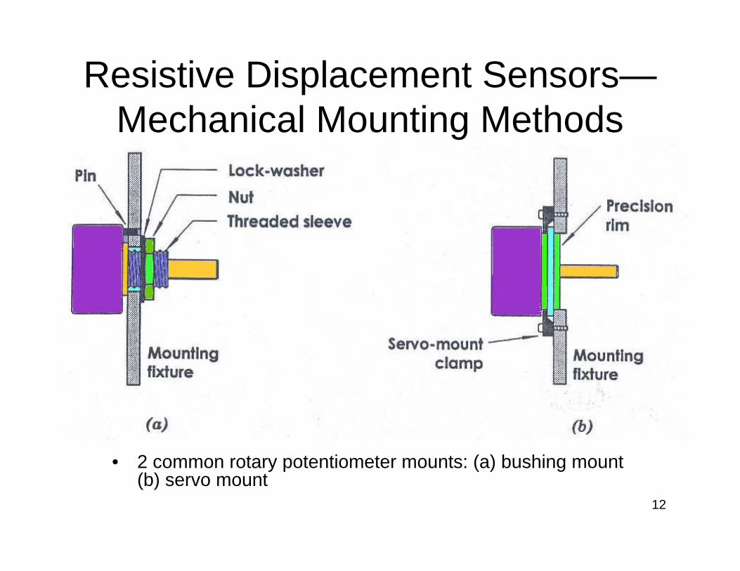
• 2 common rotary potentiometer mounts: (a) bushing mount (b) servo mount
13
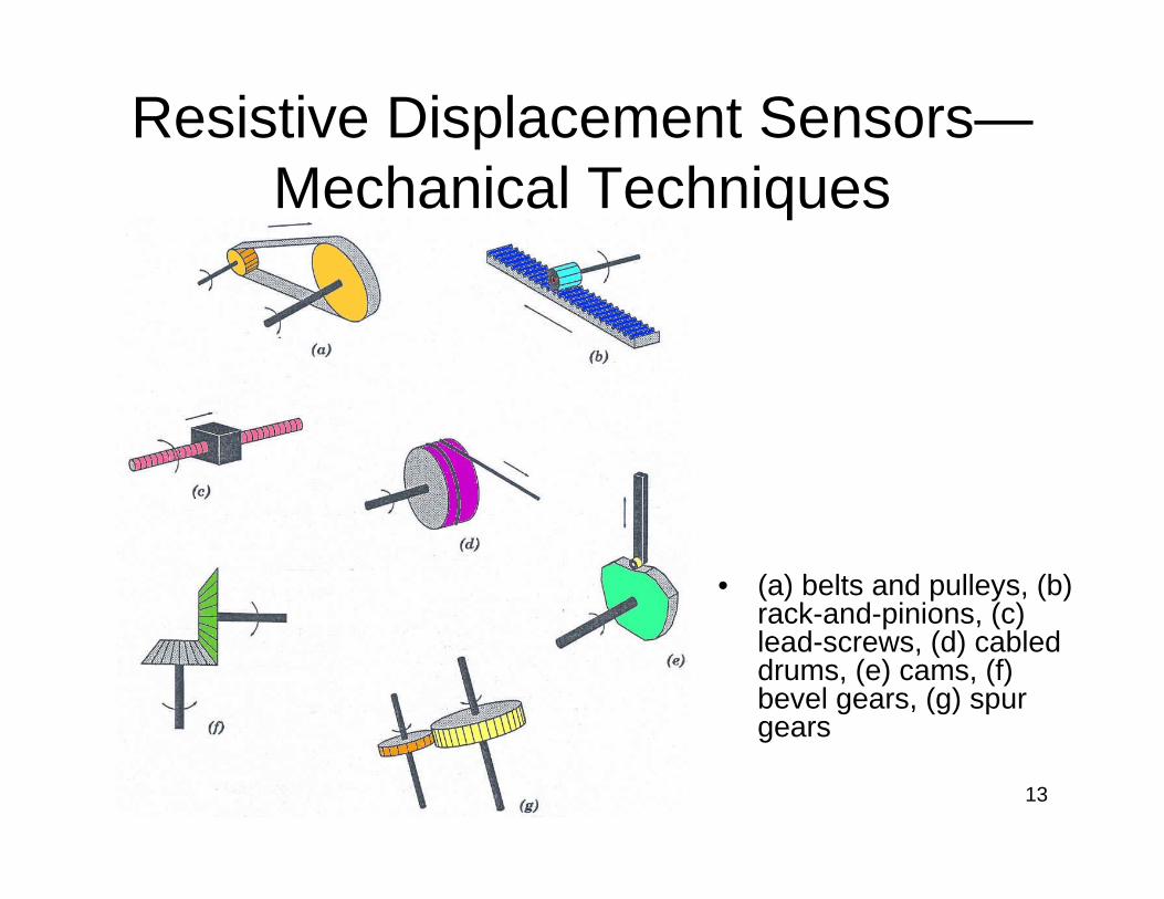
Resistive Displacement Sensors—Mechanical Techniques
• (a) belts and pulleys, (b) rack-and-pinions, (c) lead-screws, (d) cabled drums, (e) cams, (f) bevel gears, (g) spur gears
14
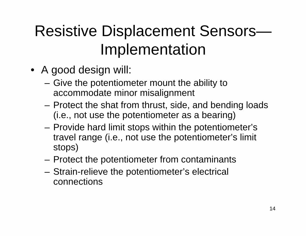
Resistive Displacement Sensors—Implementation
• A good design will:– Give the potentiometer mount the ability to
accommodate minor misalignment– Protect the shat from thrust, side, and bending loads
(i.e., not use the potentiometer as a bearing)– Provide hard limit stops within the potentiometer’s
travel range (i.e., not use the potentiometer’s limit stops)
– Protect the potentiometer from contaminants– Strain-relieve the potentiometer’s electrical
connections
15
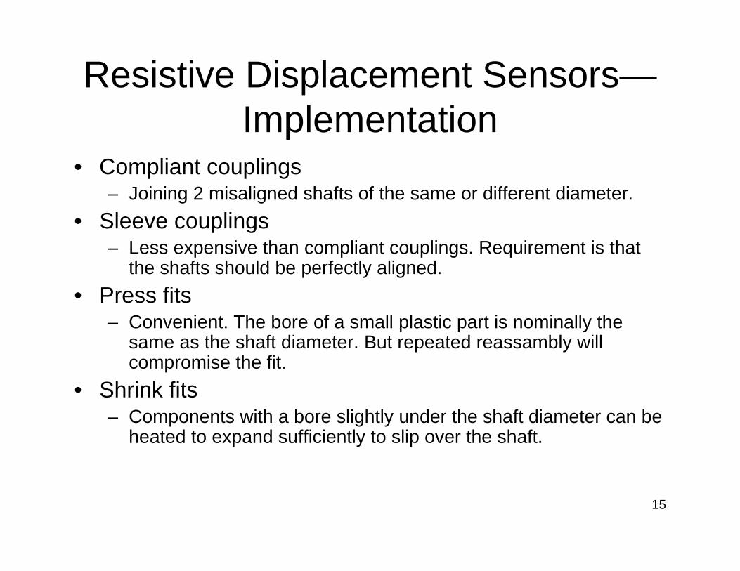
Resistive Displacement Sensors—Implementation
• Compliant couplings– Joining 2 misaligned shafts of the same or different diameter.
• Sleeve couplings– Less expensive than compliant couplings. Requirement is that
the shafts should be perfectly aligned.• Press fits
– Convenient. The bore of a small plastic part is nominally the same as the shaft diameter. But repeated reassambly will compromise the fit.
• Shrink fits– Components with a bore slightly under the shaft diameter can be
heated to expand sufficiently to slip over the shaft.
16
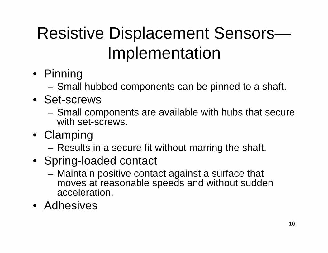
Resistive Displacement Sensors—Implementation
• Pinning– Small hubbed components can be pinned to a shaft.
• Set-screws– Small components are available with hubs that secure
with set-screws.• Clamping
– Results in a secure fit without marring the shaft.• Spring-loaded contact
– Maintain positive contact against a surface that moves at reasonable speeds and without sudden acceleration.
• Adhesives

17
Inductive Displacement Sensors
• Based on the principles of magnetic circuits.
• Classified as self-generating or passive.• Self-generating type
– When there is a relative motion between a conductor and a magnetic field, a voltage is induced in the conductor.
• Passive type– Requires an external source of power.

18
Inductive Displacement Sensors
• A basic inductive sensor consists of a magnetic circuit made from a ferromagnetic core with a coil wound on it. The coil acts as a source of magnetomotive force (mmf) that drives the flux through the magnetic circuit and the air gap. The presence of the air gap causes a large increase in circuit reluctance and a corresponding decrease in the flux. Hence, a small variation in the air gap results in a measurable change in inductance.
19
Inductive Displacement Sensors
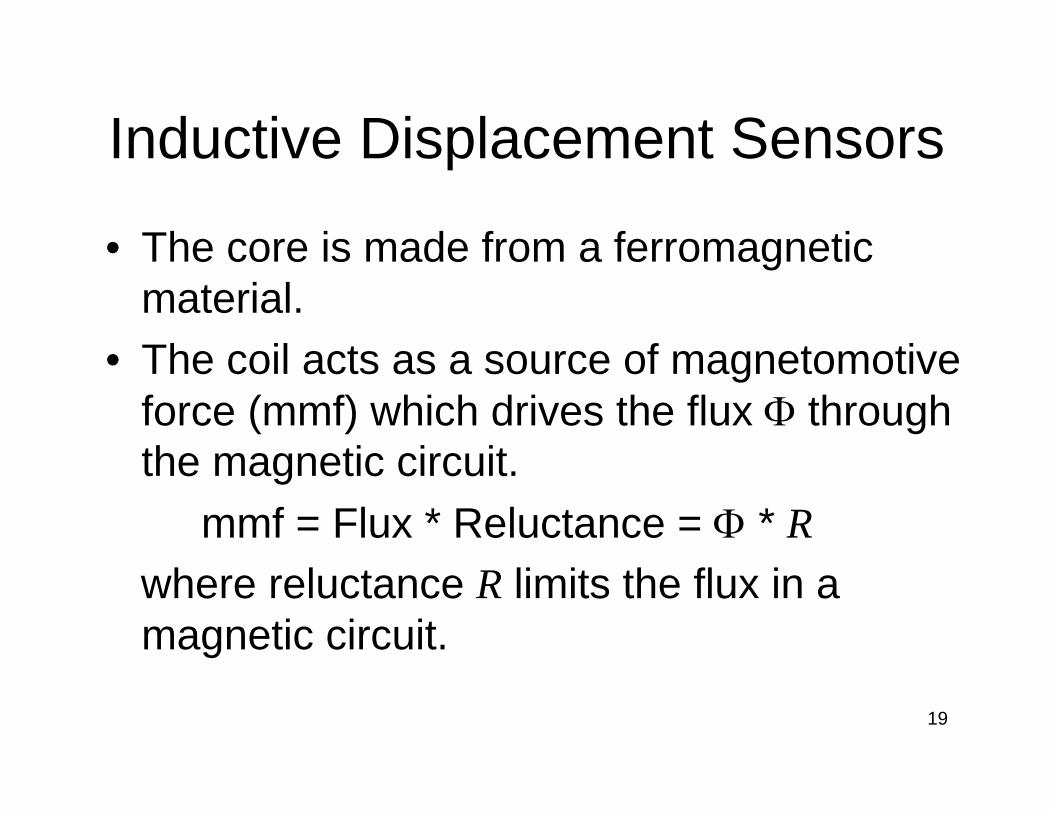
• The core is made from a ferromagnetic material.
• The coil acts as a source of magnetomotiveforce (mmf) which drives the flux Φ through the magnetic circuit.
mmf = Flux * Reluctance = Φ * Rwhere reluctance R limits the flux in a magnetic circuit.
20
Inductive Displacement Sensors
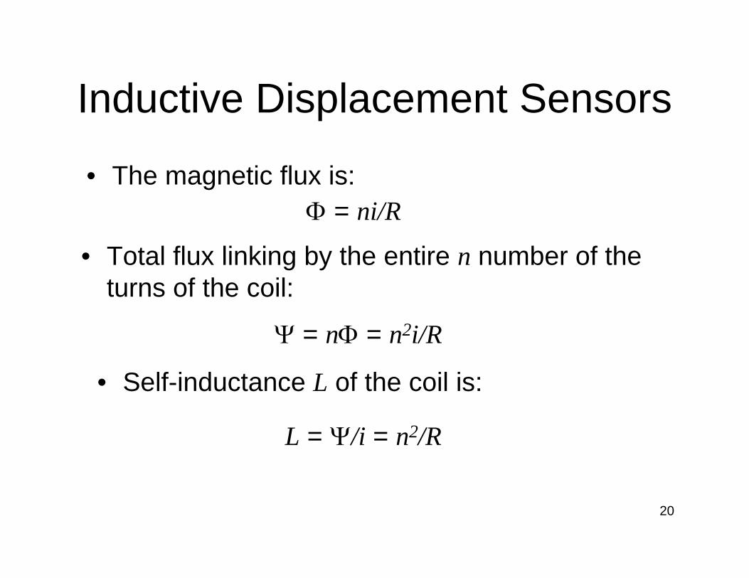
Φ = ni/R
• Total flux linking by the entire n number of the turns of the coil:
Ψ = nΦ = n2i/R
• The magnetic flux is:
• Self-inductance L of the coil is:
L = Ψ/i = n2/R
21
Inductive Displacement Sensors
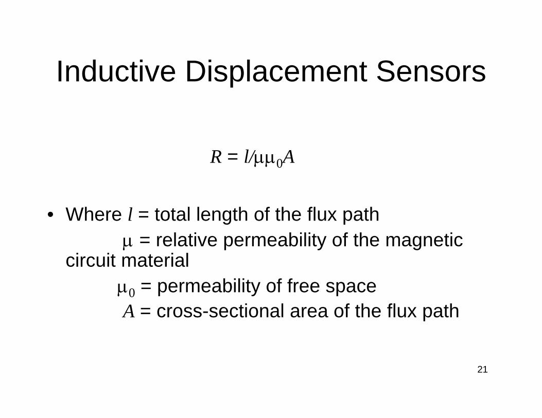
• Where l = total length of the flux pathµ = relative permeability of the magnetic
circuit materialµ0 = permeability of free spaceA = cross-sectional area of the flux path
R = l/µµ0A

22
Inductive Displacement Sensors—Linear and Rotary Variable-Reluctance Transducer
• Based on change in the reluctance of a magnetic flux path.
• Application—acceleration, displacement and velocity measurements.
23
Inductive Displacement Sensors—Single-Coil Linear Variable-Reluctance Sensor
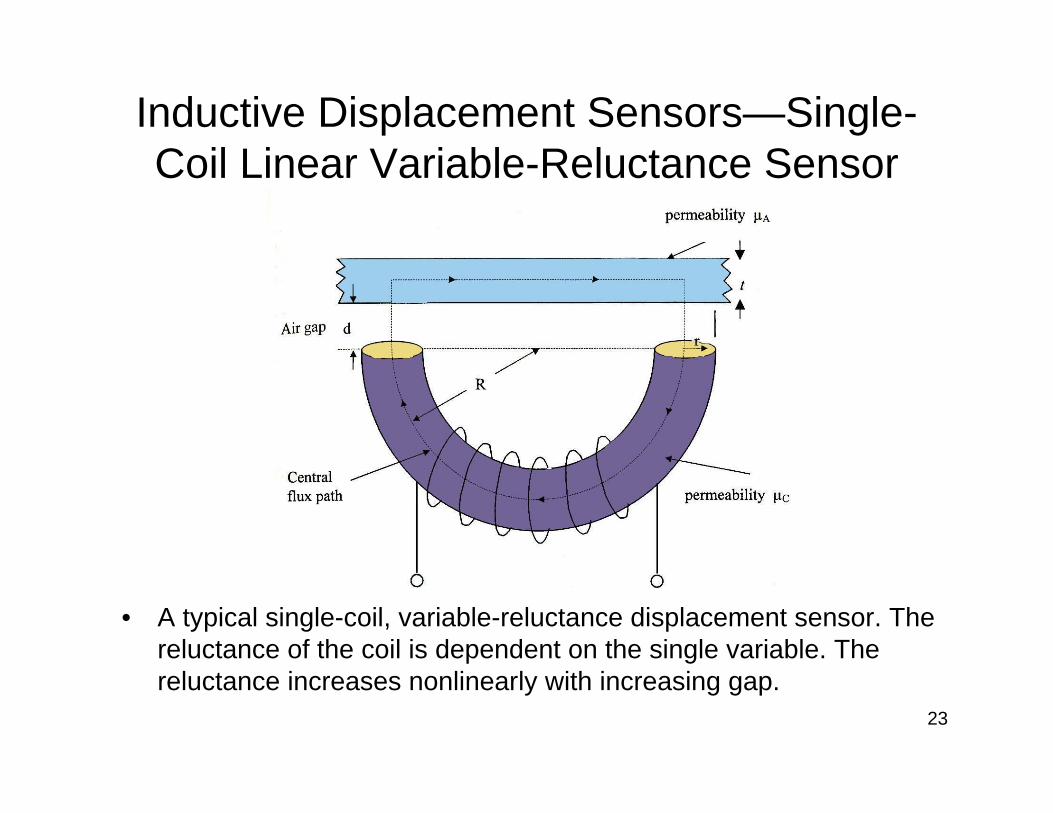
• A typical single-coil, variable-reluctance displacement sensor. The reluctance of the coil is dependent on the single variable. The reluctance increases nonlinearly with increasing gap.
24
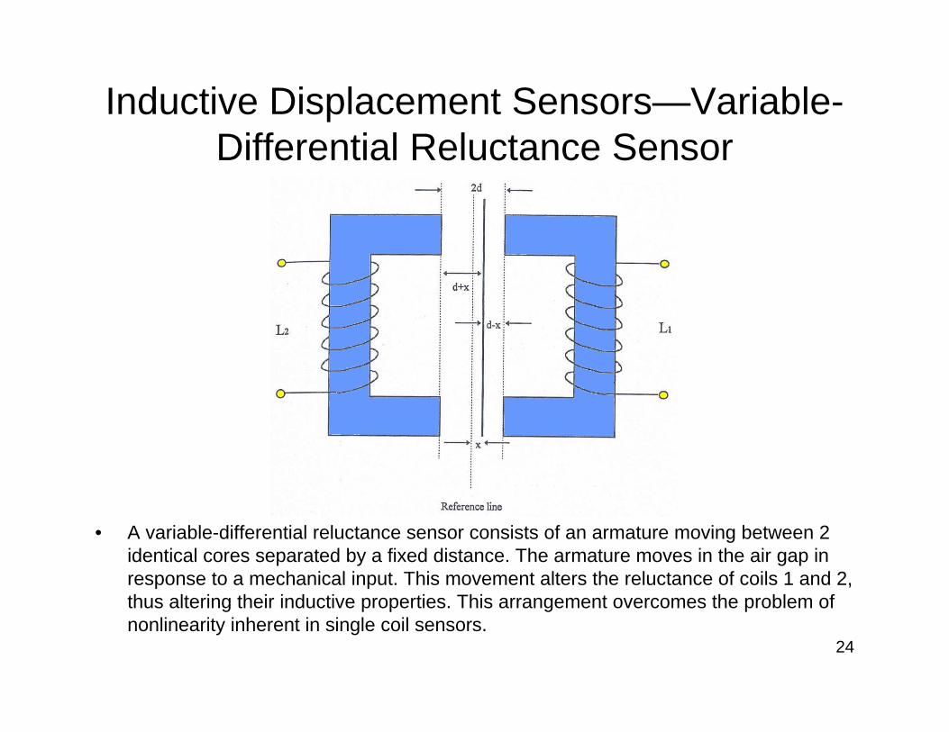
Inductive Displacement Sensors—Variable-Differential Reluctance Sensor
• A variable-differential reluctance sensor consists of an armature moving between 2 identical cores separated by a fixed distance. The armature moves in the air gap in response to a mechanical input. This movement alters the reluctance of coils 1 and 2, thus altering their inductive properties. This arrangement overcomes the problem of nonlinearity inherent in single coil sensors.
25
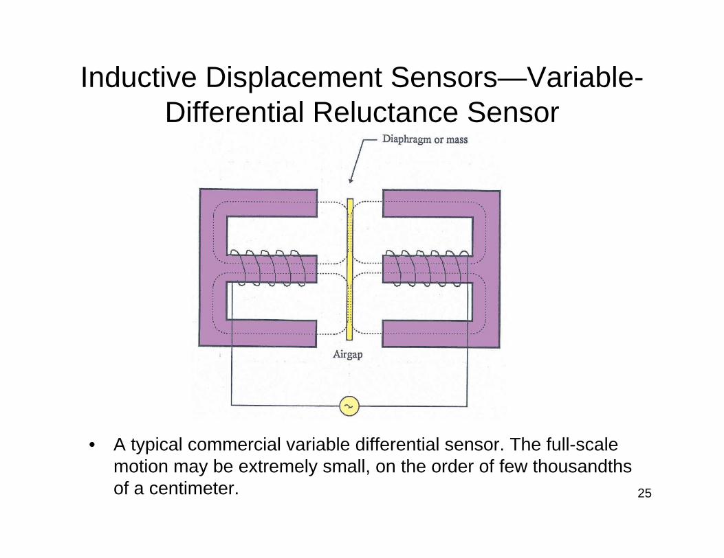
Inductive Displacement Sensors—Variable-Differential Reluctance Sensor
• A typical commercial variable differential sensor. The full-scale motion may be extremely small, on the order of few thousandths of a centimeter.

26
Inductive Displacement Sensors—Microsyn

27
Inductive Displacement Sensors—Variable-Coupling Transducers
• The core and both coils have the same length
28
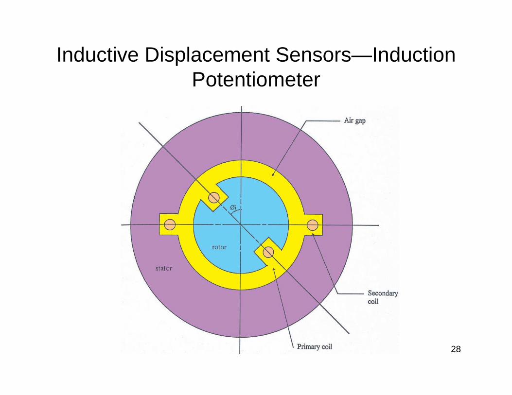
Inductive Displacement Sensors—Induction Potentiometer
29
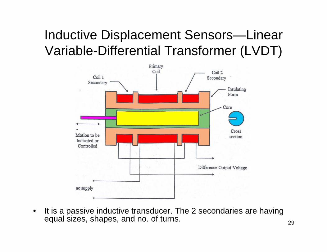
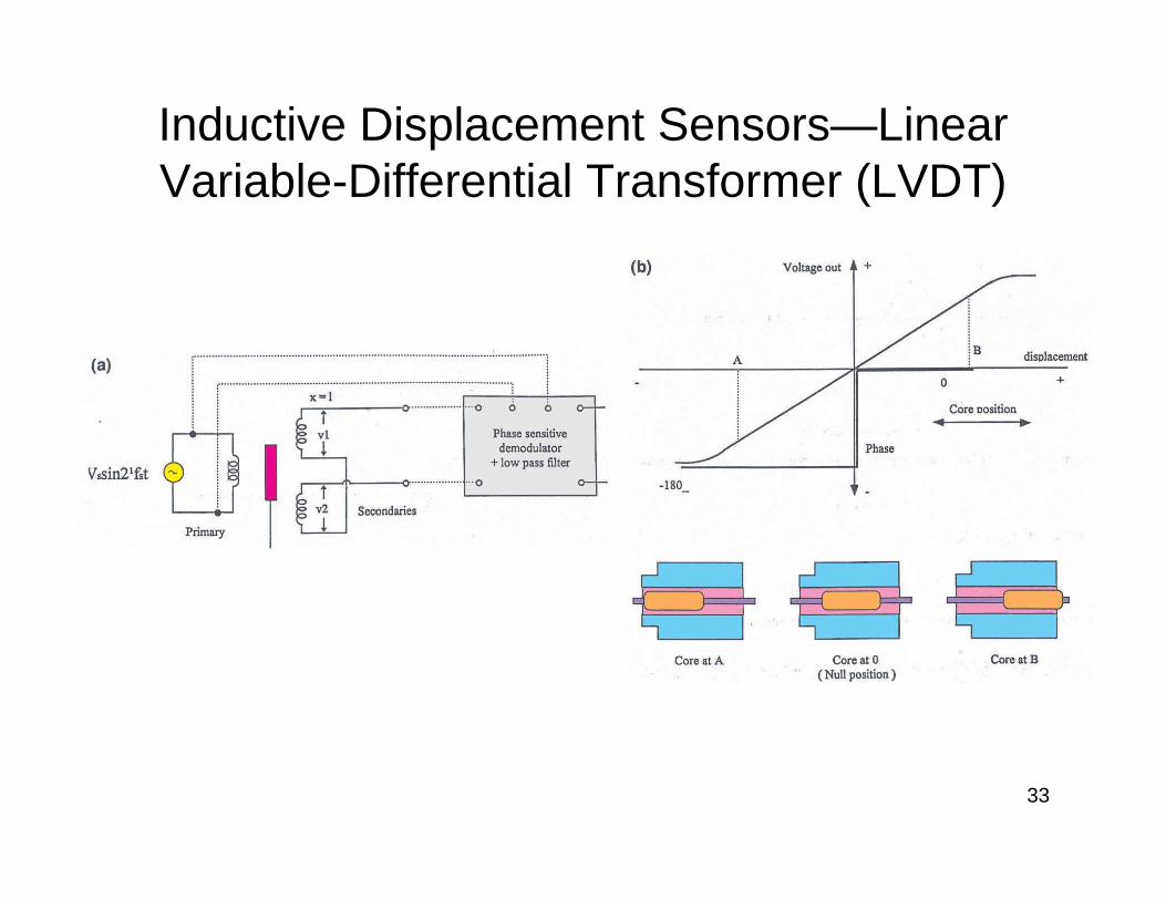
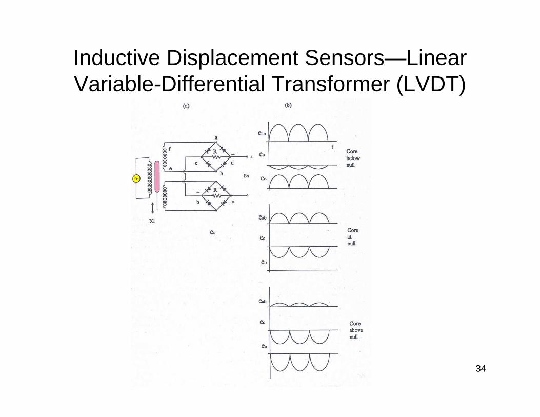
Inductive Displacement Sensors—Linear Variable-Differential Transformer (LVDT)
• It is a passive inductive transducer. The 2 secondaries are having equal sizes, shapes, and no. of turns.

30
Inductive Displacement Sensors—Linear Variable-Differential Transformer (LVDT)

31
Inductive Displacement Sensors—Linear Variable-Differential Transformer (LVDT)
• (b) The output voltages of individual secondaries v1 and v2 are at null position.
32
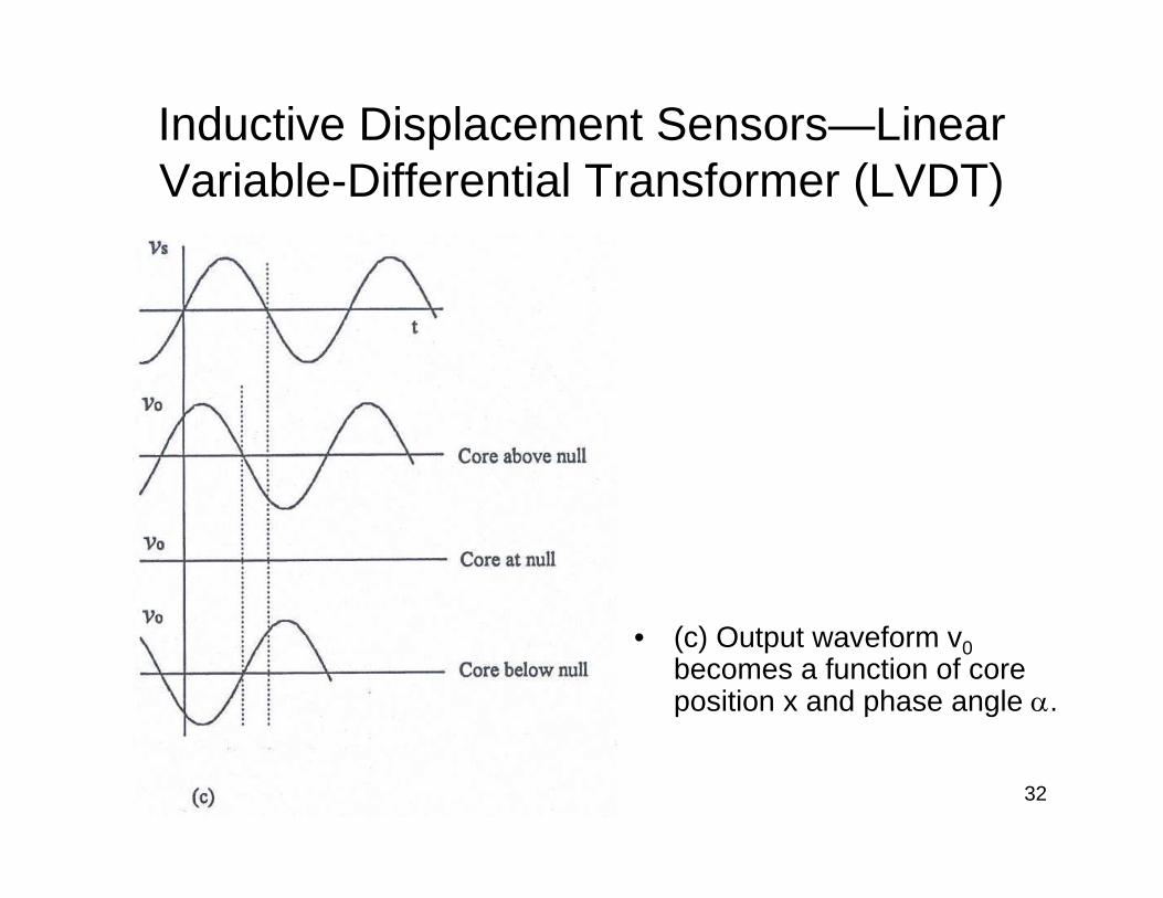
Inductive Displacement Sensors—Linear Variable-Differential Transformer (LVDT)
• (c) Output waveform v0becomes a function of core position x and phase angle α.
33
Inductive Displacement Sensors—Linear Variable-Differential Transformer (LVDT)
34
Inductive Displacement Sensors—Linear Variable-Differential Transformer (LVDT)

35
Inductive Displacement Sensors—Rotary Variable-Differential Transformer
36
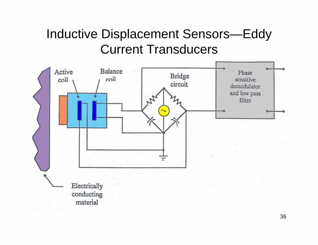
Inductive Displacement Sensors—Eddy Current Transducers
37
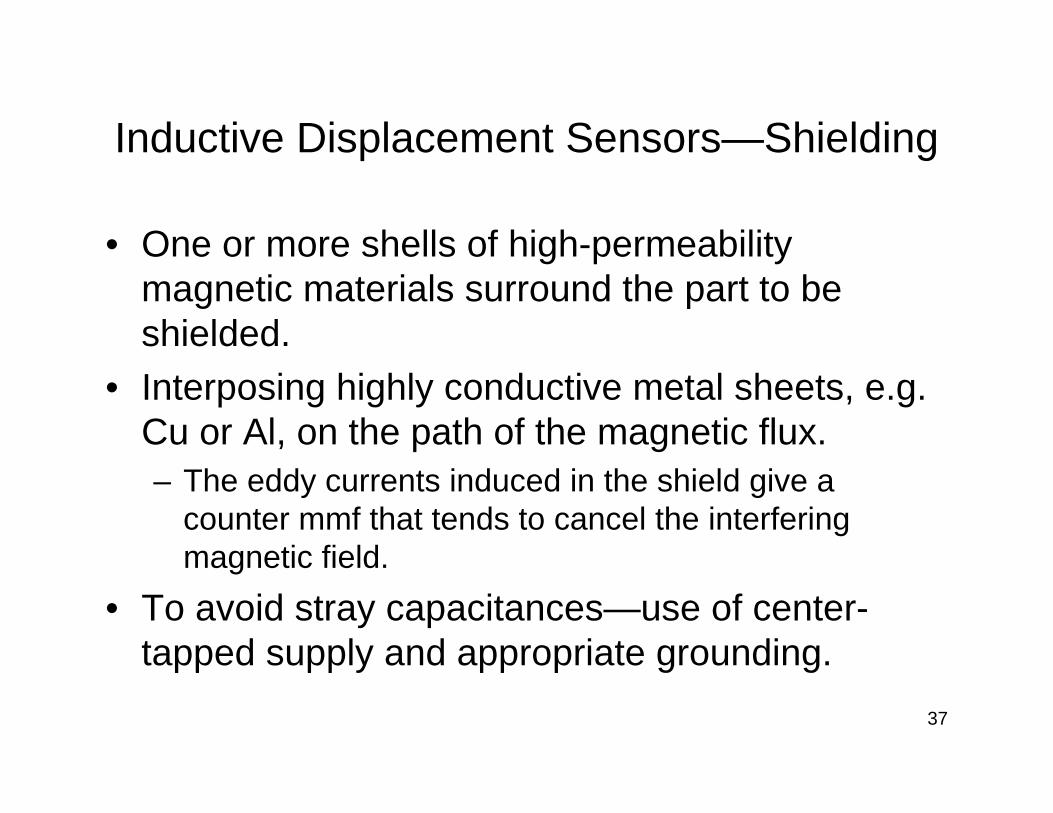
Inductive Displacement Sensors—Shielding
• One or more shells of high-permeability magnetic materials surround the part to be shielded.
• Interposing highly conductive metal sheets, e.g. Cu or Al, on the path of the magnetic flux.– The eddy currents induced in the shield give a
counter mmf that tends to cancel the interfering magnetic field.
• To avoid stray capacitances—use of center-tapped supply and appropriate grounding.
38
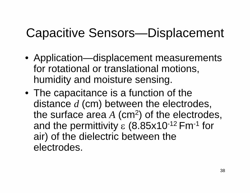
Capacitive Sensors—Displacement
• Application—displacement measurements for rotational or translational motions, humidity and moisture sensing.
• The capacitance is a function of the distance d (cm) between the electrodes, the surface area A (cm2) of the electrodes, and the permittivity ε (8.85x10⁻¹² Fm-1 for air) of the dielectric between the electrodes.

39
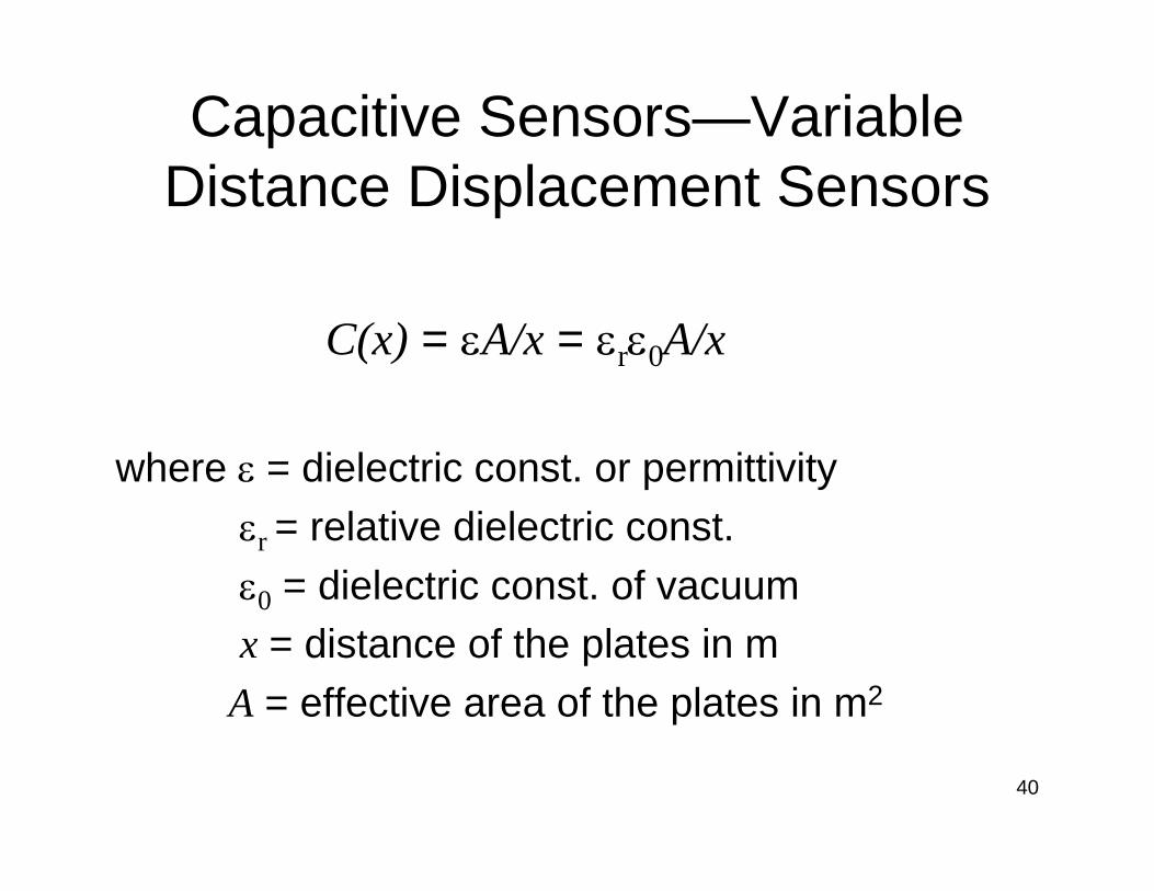
Capacitive Sensors—Variable Distance Displacement Sensors
40
Capacitive Sensors—Variable Distance Displacement Sensors
C(x) = εA/x = εrε0A/x
where ε = dielectric const. or permittivityεr = relative dielectric const.ε0 = dielectric const. of vacuumx = distance of the plates in m
A = effective area of the plates in m2
41
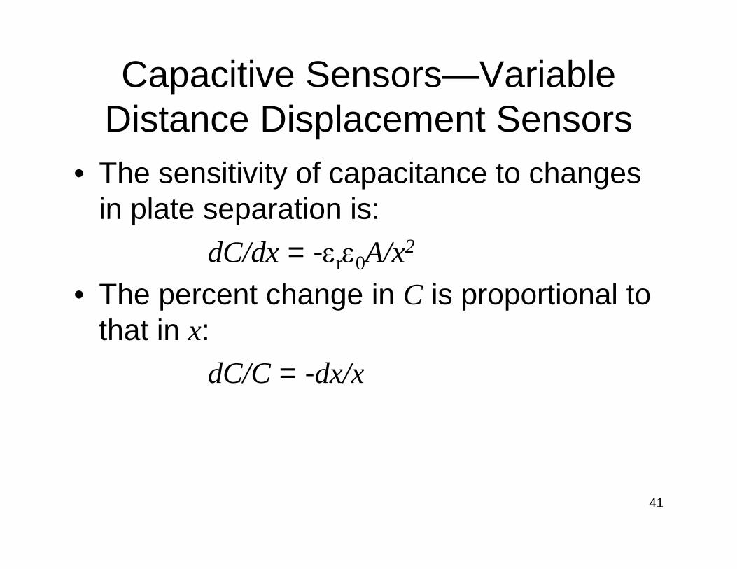
Capacitive Sensors—Variable Distance Displacement Sensors
• The sensitivity of capacitance to changes in plate separation is:
dC/dx = -εrε0A/x2
• The percent change in C is proportional to that in x:
dC/C = -dx/x

42
Capacitive Sensors—Variable Area Displacement Sensors
43
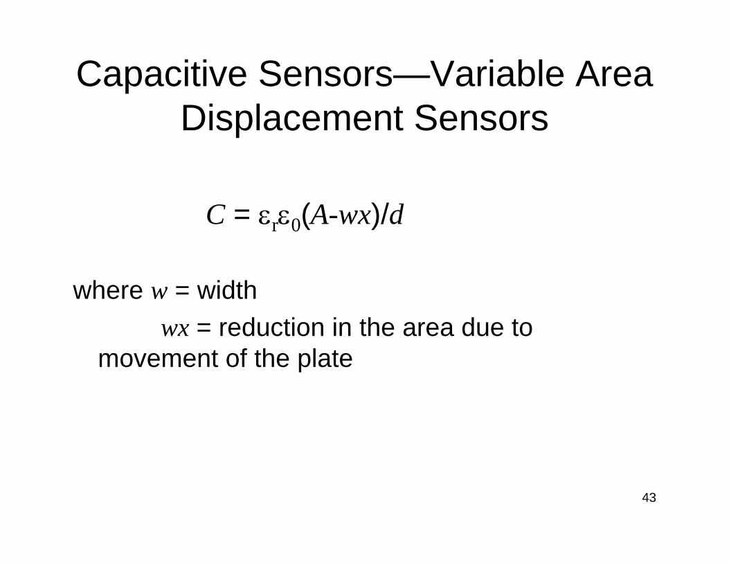
Capacitive Sensors—Variable Area Displacement Sensors
C = εrε0(A-wx)/d
where w = widthwx = reduction in the area due to
movement of the plate

44
Capacitive Sensors—Variable Dielectric Displacement Sensors
45
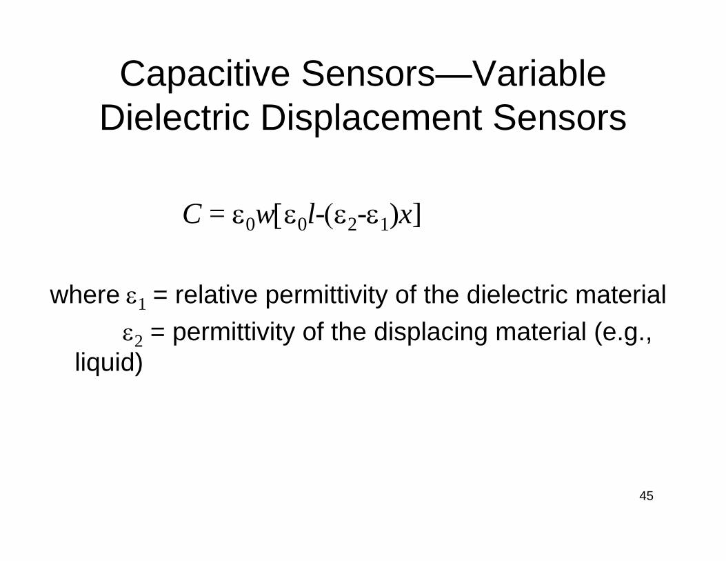
Capacitive Sensors—Variable Dielectric Displacement Sensors
C = ε0w[ε0l-(ε2-ε1)x]
where ε1 = relative permittivity of the dielectric materialε2 = permittivity of the displacing material (e.g.,
liquid)
46
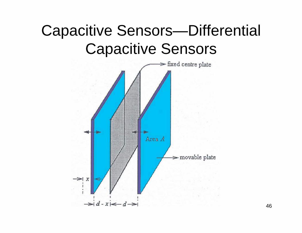
Capacitive Sensors—Differential Capacitive Sensors
47
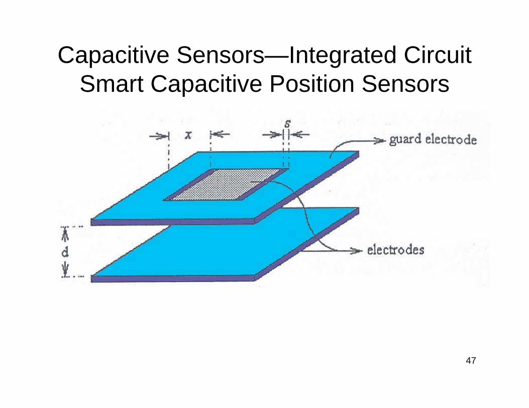
Capacitive Sensors—Integrated Circuit Smart Capacitive Position Sensors

48
Piezoelectric Transducers and Sensors
• Piezoelectricity—to describe the ability of certain materials to develop an electric charge that is proportional to a direct applied mechanical stress.
• The effect is reversible.• Piezoelectric materials will deform (strain)
proportionally to an applied electric field.• The effect is of the order of nanometers.• Applications - for example fine focusing of
optical assemblies, etc.

49
Piezoelectric Transducers and Sensors
• Ferroelectrics—an important class of piezoelectric materials.
• Closely related to the ferroelectric polarization that can be reversed by the application of sufficiently high E-field.
• To induce piezoelectric properties, polingprocedure is often required.
• Poling is analogous to the magnetizing of a permanent magnet.
50
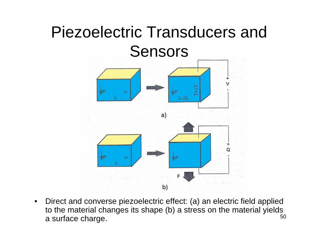
Piezoelectric Transducers and Sensors
• Direct and converse piezoelectric effect: (a) an electric field applied to the material changes its shape (b) a stress on the material yields a surface charge.

51
Piezoelectric Materials—Single Crystals
• Quartz (SiO2), Lithium Niobate (LiNbO3) and Lithium Tantalate (LiTaO3).
• Application—frequency-stabilized oscillators in watches and radars, and surface acoustic wave devices in TV filters and analog signal correlators.

52
Piezoelectric Materials—Piezoelectric Ceramics
• Polling process in piezoelectric ceramics: (a) in the absence ofan electric field (b) in the electric field.

53
Piezoelectric Materials—Piezoelectric Ceramics
• Applying a strong dc E-field at a temperature just below the Curie temperature, poling procedure is induced.
• Made up of mixed oxides containing corner-sharing octahedra of O2- ions, which is the Perovskite family.

54
Piezoelectric Materials—Perovskites
• General formula is ABO3.• E.g. BaTiO3.• It is stable, has a wide temperature range
of operation, and is easily manufacturable.
55
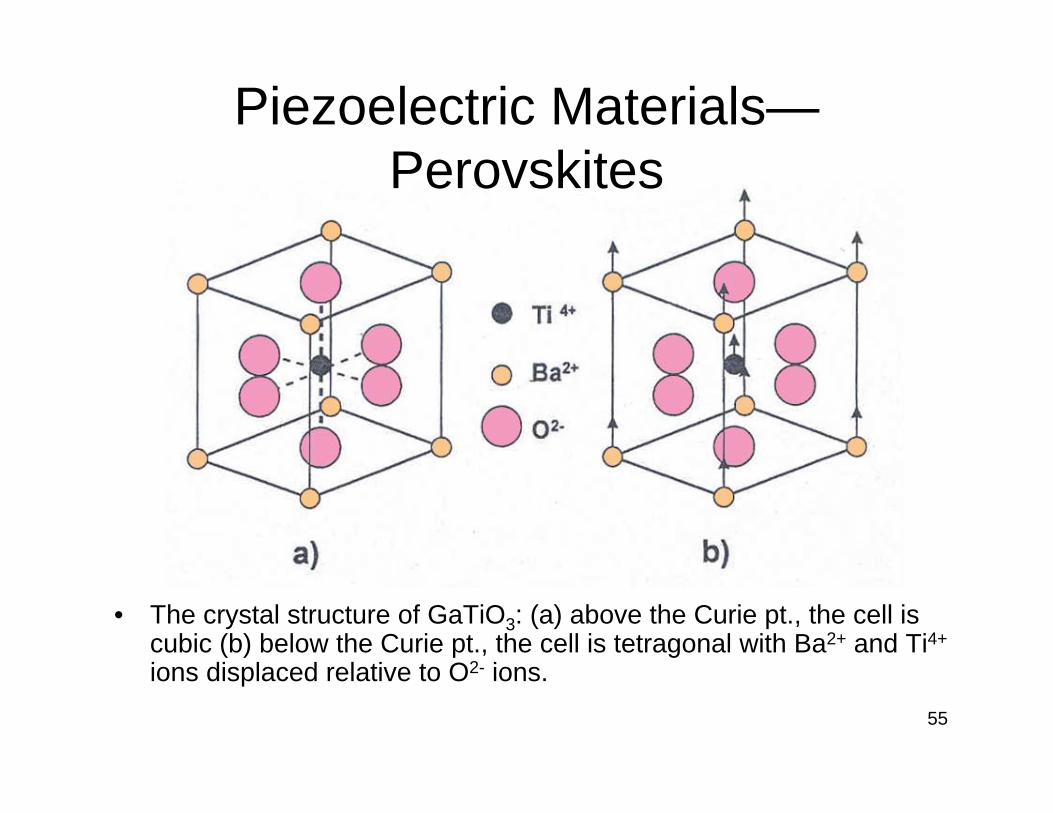
Piezoelectric Materials—Perovskites
• The crystal structure of GaTiO3: (a) above the Curie pt., the cell is cubic (b) below the Curie pt., the cell is tetragonal with Ba2+ and Ti4+
ions displaced relative to O2- ions.

56
Piezoelectric Materials—Piezoelectric Polymers
• When the polymer is drawn, or stretched, the regions become polar, and can be poled by applying a high E-field.
• The electromechanical properties of piezoelectric polymers are significantly lower than those of piezoelectric ceramics.
57
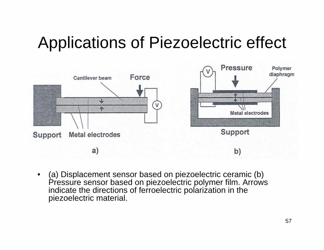
Applications of Piezoelectric effect
• (a) Displacement sensor based on piezoelectric ceramic (b) Pressure sensor based on piezoelectric polymer film. Arrows indicate the directions of ferroelectric polarization in the piezoelectric material.
58
Applications of Piezoelectric effect
• Convert electrical energy to mechanical energy, vice versa.
• Passive mode– The transducer only receives signals.– Obtain voltage from an external stress.– Applications: microphones, vibrational sensor.
• Active mode– The transducer changes its dimensions and sends an
acoustic signal into a medium.– Applications: ink jet printers, micropumps, medical
ultrasonic imaging.

59
Time-of-Flight Ultrasonic Displacement Sensors
• Principle of a pulse-echo ultrasound system for distance measurements.
60
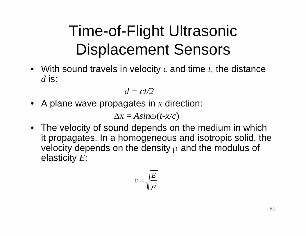
Time-of-Flight Ultrasonic Displacement Sensors
• With sound travels in velocity c and time t, the distance d is:
d = ct/2• A plane wave propagates in x direction:
∆x = Asinω(t-x/c)• The velocity of sound depends on the medium in which
it propagates. In a homogeneous and isotropic solid, the velocity depends on the density ρ and the modulus of elasticity E:
ρEc =

61
Ultrasound Transducers
• Convert electric energy to mechanical energy, vice versa.
• Common types of in-air transducers are:– Mechanical– Electromagnetic– Piezoelectric– Electrostatic– Magnetostrictive

62
Principles of Time-of-Flight Systems
• Pulse echo method• Phase angle method• Frequency modulation method• Correlation method

63
Principles of Time-of-Flight Systems
Make relatively high demands on hardware and/or computations
Very robust against disturbances
Correlation method
Measurements on long and short distances can give the same result (compare with phase angle method)
Robust against disturbances; multireflections detectable
Frequency modulation method
Cannot be used directly at distances longer than the wavelength of the ultrasound
Rather insensitive to disturbances
Phase angle method
Low signal-to-noise ratioSimplePulse echo method
DisadvantageAdvantageMethod
64
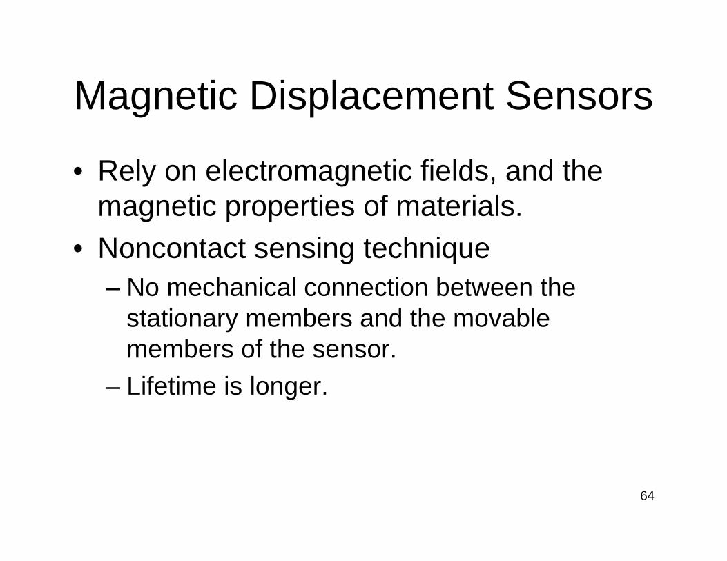
Magnetic Displacement Sensors
• Rely on electromagnetic fields, and the magnetic properties of materials.
• Noncontact sensing technique– No mechanical connection between the
stationary members and the movable members of the sensor.
– Lifetime is longer.

65
Magnetic Displacement Sensors
• Magnetic field intensity (H), or magnetizing force– The force that drives the generation of
magnetic flux in a material.– Unit: Am-1
• Magnetic flux density (B)– The amount of magnetic flux resulting from
the applied magnetizing force.– Unit: Teslas (T) or N/(A*m)
66
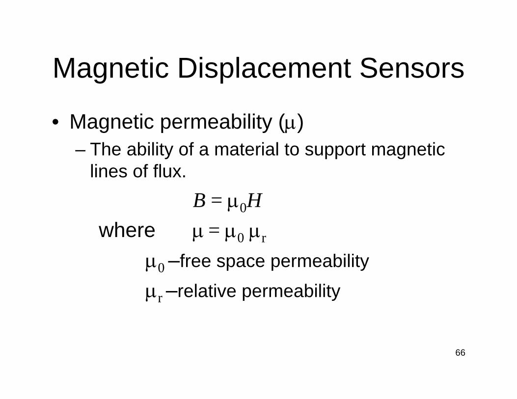
Magnetic Displacement Sensors
• Magnetic permeability (µ)– The ability of a material to support magnetic
lines of flux.B = µ0H
where µ = µ0 µr
µ0 –free space permeabilityµr –relative permeability

67
Magnetostrictive Sensors
68
Magnetostrictive Sensors
69
Magnetostrictive Sensors
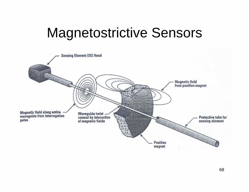
• Using a ferromagnetic element to detect the location of a position magnet that is displaced along its length.
70
Hall Effect (negative charge carriers)
(http://hyperphysics.phy-astr.gsu.edu/hbase/magnetic/hall.html)

71
Hall Effect
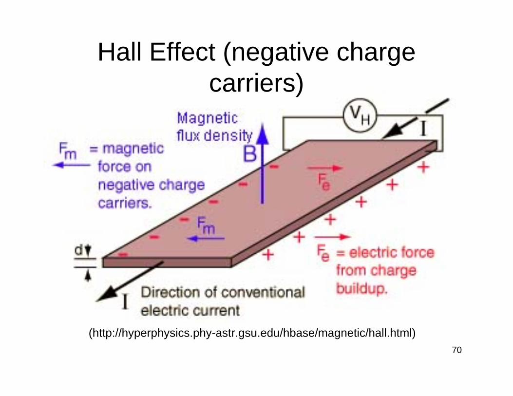
• If a current flows through a conductor in a magnetic field, the magnetic field will exert a lateral force on the moving charge carriers.
• A buildup of charge at the sides of the conductor will balance this magnetic influence, producing a measurable voltage between the two sides of the conductor. This measurable lateral voltage is called the Hall effect.
72
Hall Effect
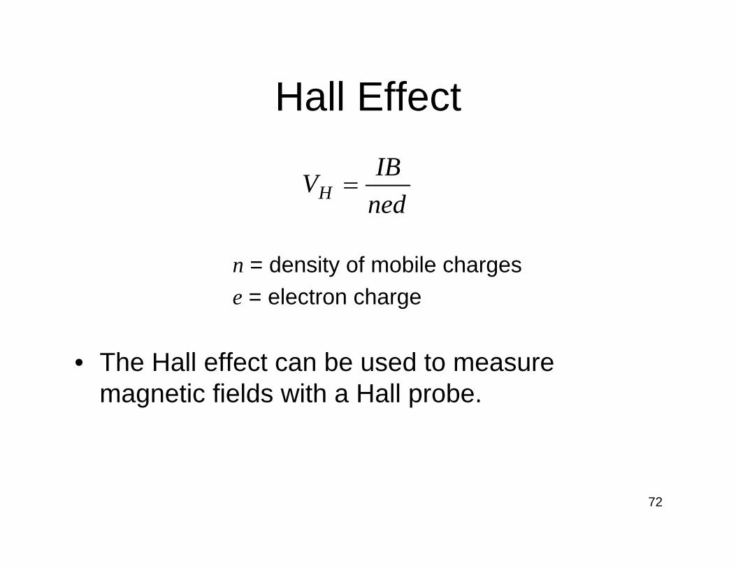
• The Hall effect can be used to measure magnetic fields with a Hall probe.
n = density of mobile chargese = electron charge
nedIBVH =
73
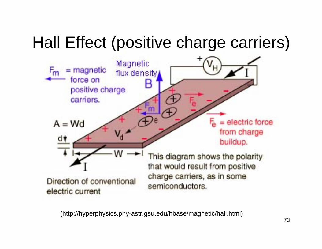
Hall Effect (positive charge carriers)
(http://hyperphysics.phy-astr.gsu.edu/hbase/magnetic/hall.html)
74
Hall Effect
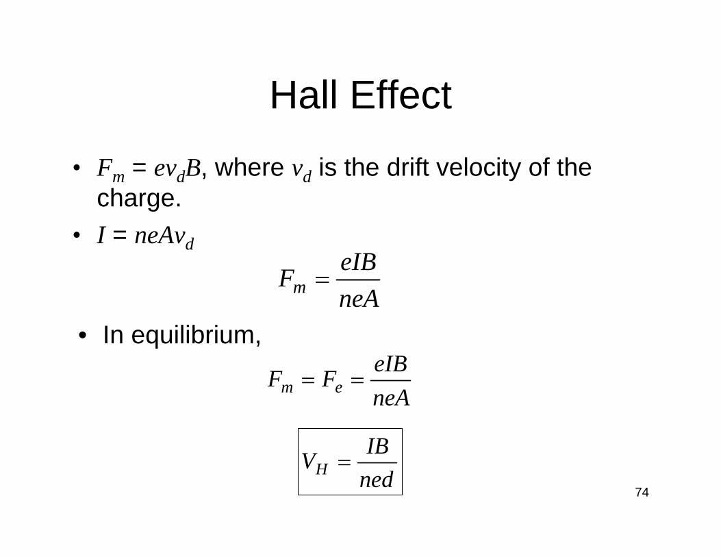
• Fm = evdB, where vd is the drift velocity of the charge.
• I = neAvd
neAeIBFm =
• In equilibrium,
neAeIBFF em ==
nedIBVH =

75
Hall Effect Sensors
• Two magnet hall sensor

76
Laser Interferometer Displacement Sensors
• Helium-neon laser

77
Michelson Interferometer
78
Optical Encoder Displacement Sensors
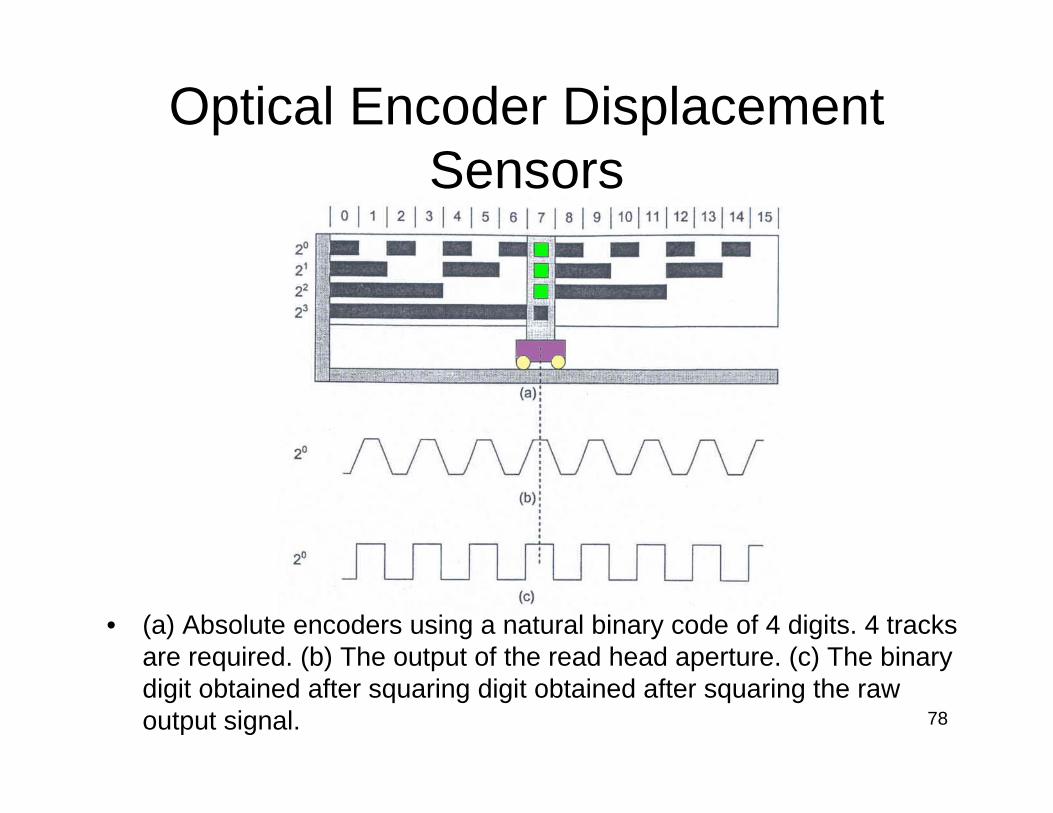
• (a) Absolute encoders using a natural binary code of 4 digits. 4 tracks are required. (b) The output of the read head aperture. (c) The binary digit obtained after squaring digit obtained after squaring the raw output signal.
79
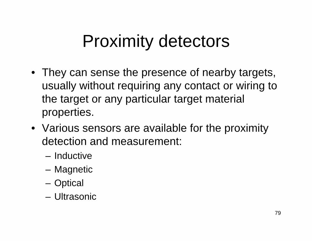
Proximity detectors
• They can sense the presence of nearby targets, usually without requiring any contact or wiring to the target or any particular target material properties.
• Various sensors are available for the proximity detection and measurement:– Inductive– Magnetic– Optical– Ultrasonic

80(http://www.clickautomation.com/products/index.php?func=list&cid=34)
Inductive Sensor Capacitive Sensor
Laser Sensor
Ultrasonic Sensor
81
Applications
• Motion detection– Detection of rotating
motion• Motion control
– Movement indication• Process control
– Automatic filling
• Sequence control– Verification and
counting• Liquid level detection
– Tube high-low liquid level
• Material level control– Low level limit
82
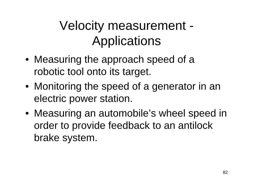
Velocity measurement -Applications
• Measuring the approach speed of a robotic tool onto its target.
• Monitoring the speed of a generator in an electric power station.
• Measuring an automobile’s wheel speed in order to provide feedback to an antilock brake system.

83
Measurement of Linear Velocity
84
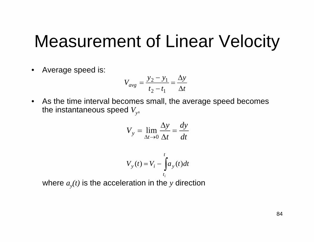
Measurement of Linear Velocity• Average speed is:
• As the time interval becomes small, the average speed becomes the instantaneous speed Vy,
where ay(t) is the acceleration in the y direction
ty
ttyyVavg ∆
∆=
−−
=12
12
dtdy
tyV
ty =∆∆
=→∆ 0
lim
dttaVtVt
tyiy
i
)()( ∫−=

85
Reference-Based Measurement
• Velocity = displacement / time taken.• To measure the displacement, there are 2
pickups by displacement sensors.• Measuring the time interval with an
electronic counter or displaying the output of the pickups from displacement sensors on an oscilloscope.

86
Doppler Shift
• When the source and observer are in motion relative to each other, there is Doppler Shift.
• It is applicable to waves, e.g. sound, light, microwaves, etc.
• Application: radar.

87
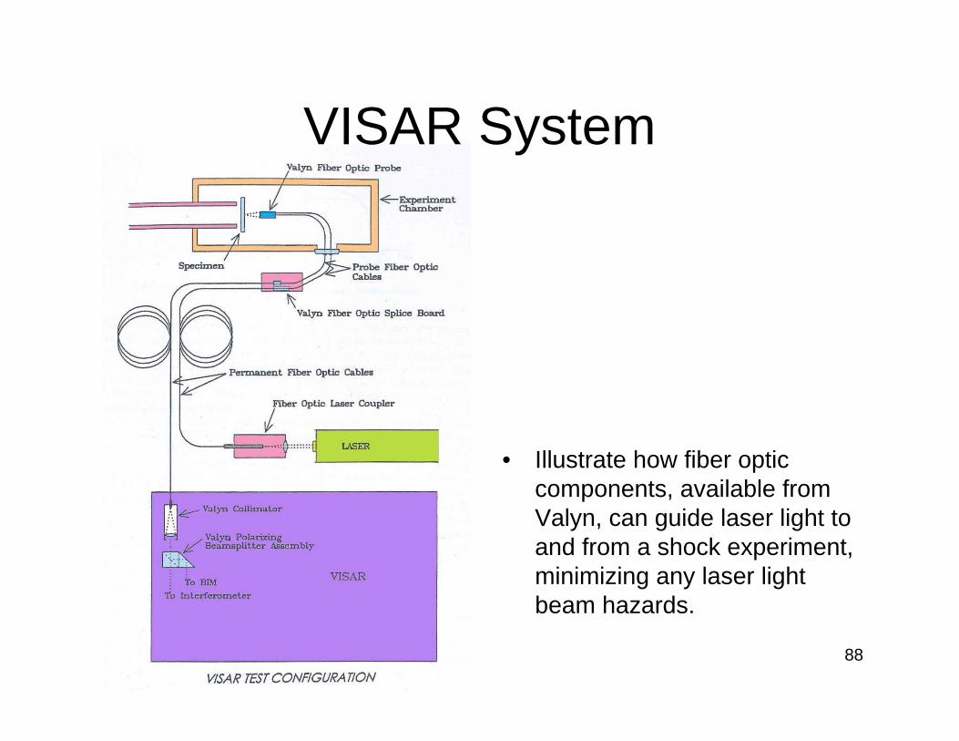
VISAR System
• Velocity Interference System for Any Reflector
• Can be used with either specularly or diffusely reflecting surfaces, and is quite insensitive to tilting of the target.
• It was developed for shock wave research work
• Useful for measurement of very high speeds.
88
VISAR System
• Illustrate how fiber optic components, available from Valyn, can guide laser light to and from a shock experiment, minimizing any laser light beam hazards.
89
Angular Velocity Measurement
• Often applied to rotating machinery such as pumps, engines, and generators.
• Most familiar unit: revolutions per minute (rpm)

90
Electrical (dc and ac) Tachometer Generator
• A rotating generator produces a voltage signal proportional to the rotational velocity of the input shaft.
• Permanent-magnet dc tach-generator

91
Counter Types• Rotating Magnet Sensors—passive speed sensors
convert mechanical motion to ac voltage without an external power source. These self-contained magnetic sensors produce a magnetic field that, when in the proximity of ferrous objects in motion, generates a voltage.
• Applications for these types of sensors:– Transmission speed– Engine rpm– Pump shaft speed– Computer peripheral speeds

92
Counter Types
• Magnetic speed sensor output voltage against speed
93
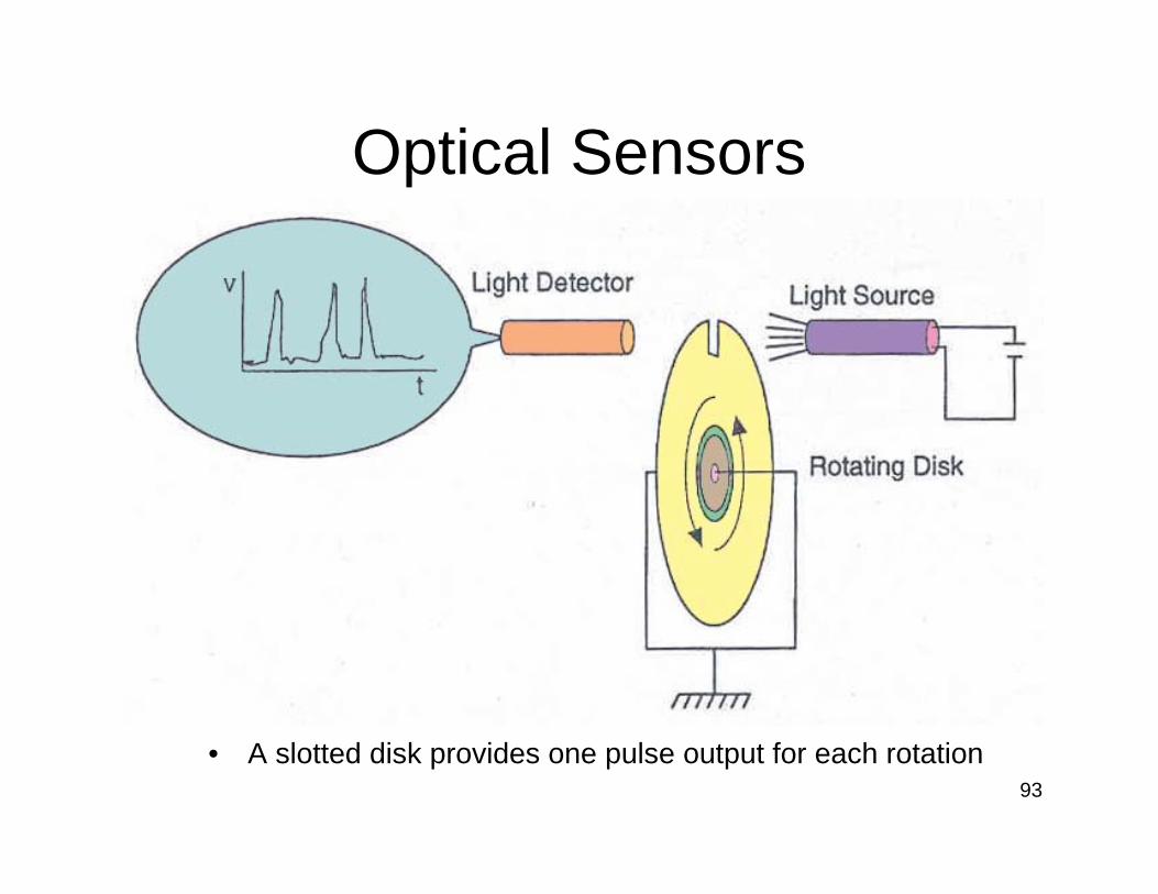
Optical Sensors
• A slotted disk provides one pulse output for each rotation

94
Stroboscope
• An oscillator produces a pulse wave of a known frequency. This is then used to drive a bright LED, which can cope with the fast rate of flashing.
• Note: a bulb cannot be used since when it is driven at a high frequency, the filament remains hot when the power goes off, and the light that is not flashing at all, but is permanently on.
(http://homepages.which.net/~paul.hills/Circuits/Stroboscope/Stroboscope.html)

95
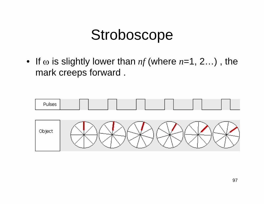
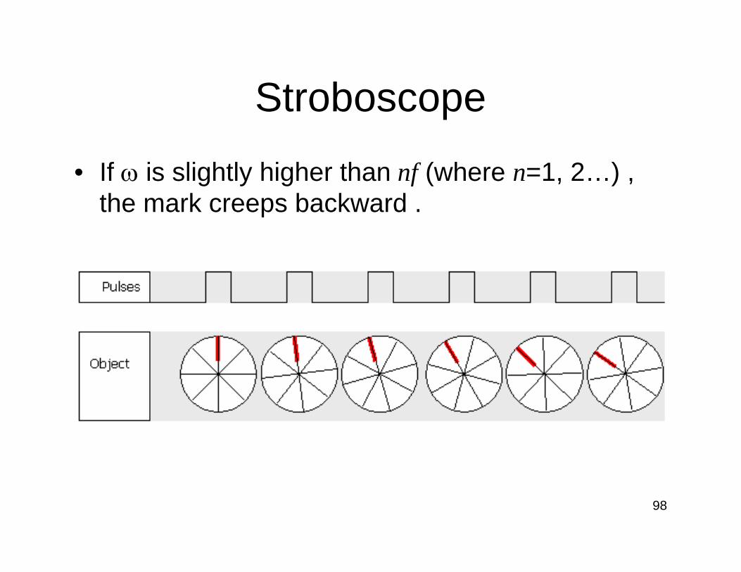
Stroboscope
• A mark is made on the object.• If the rotational velocity ω of the object is not
matched with the frequency f of the oscillator, random appearance of the mark is seen.

96
Stroboscope
• If ω = nf (where n=1, 2…) , the mark becomes stationary.
97
Stroboscope
• If ω is slightly lower than nf (where n=1, 2…) , the mark creeps forward .
98
Stroboscope
• If ω is slightly higher than nf (where n=1, 2…) , the mark creeps backward .
99
Wiegand Effect
• It employs unique magnetic properties of specially processed, small-diameter ferromagnetic wire.
• By causing the magnetic field of this wire to suddenly reverse, a sharp, uniform voltage pulse is generated.
• Wiegand pulse.

100
Wiegand Effect
• It is useful for proximity sensing, tachometry, rotary shaft encoding, and speed sensing.
• Application:– Electronic indexing for water, gas, and electric
meters.– Measuring shaft speed in engines.– Tachometers, speedometers, and other
rotational counting devices.
101
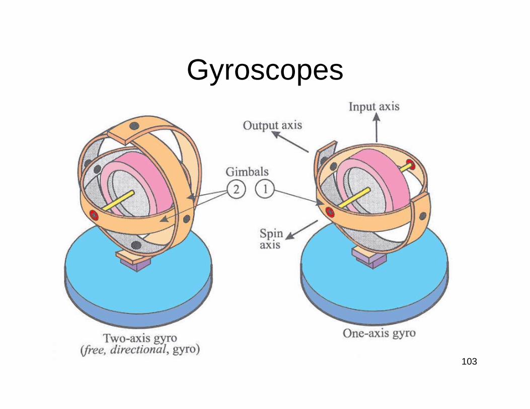
Angular Rate Sensors—Gyroscopes
• Many absolute angular rate-measuring devices fall under the designation of gyroscope.
• It consists of a spinning mass mounted on a base so that its axis can turn freely in one or more directions.
• Angular velocity gyros are used to measure motion and as signal inputs to stabilization systems.
• Rate-integrating gyros are used as the basis for highly accurate inertial navigation systems.
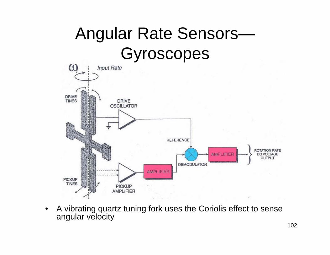
102
Angular Rate Sensors—Gyroscopes
• A vibrating quartz tuning fork uses the Coriolis effect to sense angular velocity
103
Gyroscopes
Related Documents