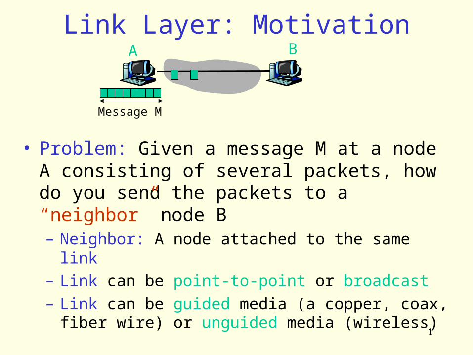
1 Link Layer: Motivation Message M A B • Problem: Given a message M at a node A consisting of several packets, how do you send the packets to a “neighbor” node B – Neighbor: A node attached to the same link – Link can be point-to-point or broadcast – Link can be guided media (a copper, coax, fiber wire) or unguided media (wireless)

1 Link Layer: Motivation Message M A B Problem: Given a message M at a node A consisting of several packets, how do you send the packets to a “neighbor”
Dec 19, 2015
Welcome message from author
This document is posted to help you gain knowledge. Please leave a comment to let me know what you think about it! Share it to your friends and learn new things together.
Transcript
1
Link Layer: Motivation
Message M
A B
• Problem: Given a message M at a node A consisting of several packets, how do you send the packets to a “neighbor” node B– Neighbor: A node attached to the same link – Link can be point-to-point or broadcast– Link can be guided media (a copper, coax, fiber
wire) or unguided media (wireless)

2
Link and Physical Layers
• This communication problem is handled by 2 protocols– A Link Layer (LL) that sits on top of the physical layer (PL)
and deals with• Packet Encapsulation, Mux/Demux• Framing – Detecting frame boundaries• Error Detection/Recovery – Detecting corrupt frames• Media Access Control (if the link is multi-access or broadcast)
• Reliable delivery, flow control? – Optional– A Physical Layer (PL)
• deals with encoding/decoding bits of a frame to/from the link
Message M
A Blink
physical
linkphysica
l

3
Network Interface Card (NIC)
• LL in part, PL in total are implemented in NIC– Ethernet card, 802.11 card, …– NIC is semi-autonomous
• Listens to the link independent of the CPU• Talks to CPU after reception of a new frame• CPU talks to the card to send a frame
– Has connectivity to both the I/O bus and the network link
CPU
cache
Memory
I/O Bus Link
Businterface
Linkinterface
NICI/O Bus Interface
PCILink
Interface
LinkInterface

4
Link Layer Service Interface• Every Link Layer must export a service
interface to the layers on top of it– Unreliable frame service
• Corrupt frames are not recovered, frame sending order may not be preserved
• OK when error rate is low so packet recovery is left to upper layers – Most wired links are of this type
– Reliable, unordered frame service• Corrupt frames are recovered, frame sending order
may not be preserved, also duplicate packets possible?• Good for links where the error rate is high such as
wireless links
– Reliable, ordered frame service• Corrupt frames are recovered, frames are delivered in
the order they were sent, no duplicate frames possible.• Very restrictive! X.25 links used this model
5
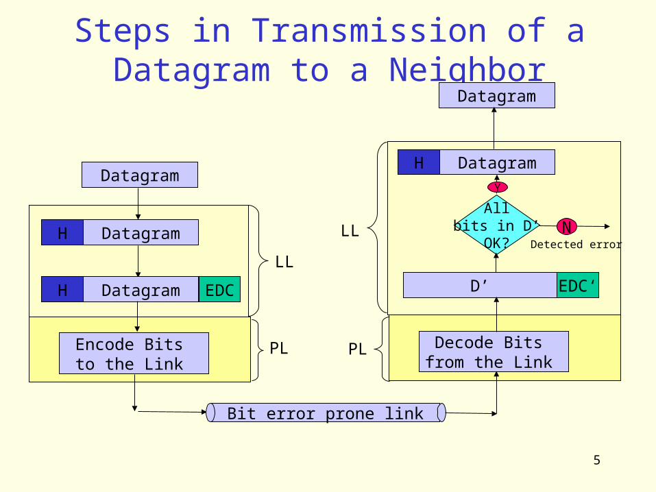
Steps in Transmission of a Datagram to a Neighbor
Datagram
DatagramH
DatagramH EDC
Bit error prone link
Datagram
DatagramH
D’ EDC‘
LL
Allbits in D’
OK?N
Detected error
Y
Encode Bits to the Link
LL
Decode Bits from the Link
PL PL
6
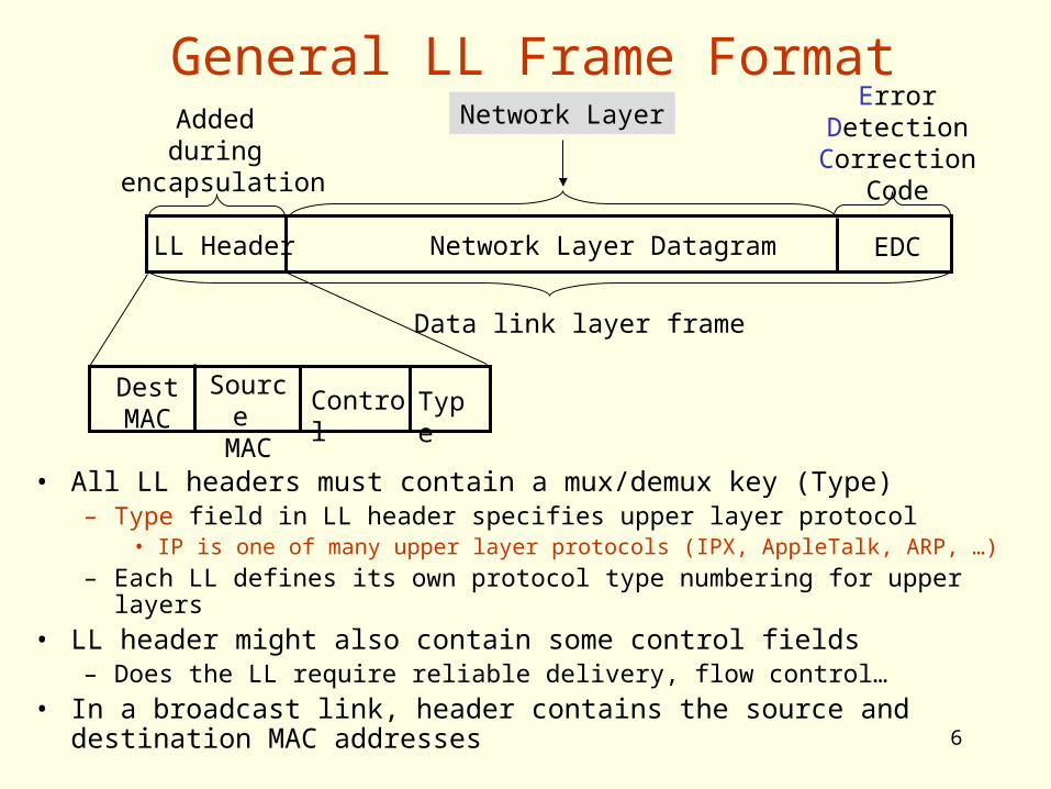
General LL Frame Format
LL Header Network Layer Datagram
Data link layer frame
Added during
encapsulation
Network Layer
EDC
ErrorDetectionCorrection
Code
Type
Dest MAC
Source
MAC
Control
• All LL headers must contain a mux/demux key (Type)– Type field in LL header specifies upper layer protocol
• IP is one of many upper layer protocols (IPX, AppleTalk, ARP, …)– Each LL defines its own protocol type numbering for upper layers
• LL header might also contain some control fields– Does the LL require reliable delivery, flow control…
• In a broadcast link, header contains the source and destination MAC addresses
7
Upper layer protocol numbersin Ethernet
• http://www.cavebear.com/CaveBear/Ethernet/type.html
• Some Ethernet protocol types– 0800 DOD Internet Protocol (IP) – 0806 Address Resolution Protocol (ARP)– 8037 IPX (Novell Netware) – 80D5 IBM SNA Services– 809B EtherTalk (AppleTalk over Ethernet)
8
Maximum Transfer Unit (MTU)
• Each LL has a limit on the max. LL frame size– This limit is called the “Maximum Transfer Unit”
MTU of the link– MTU is the maximum frame size including the LL
header, trailer etc.– If a higher layer protocol such as IP wants to
send a datagram bigger than the LL MTU, it has to break the datagram into smaller pieces (fragments), so that each fragment is smaller than the MTU
– This is called fragmentation (at the sender) and de-fragmentation (at the receiver)
9
Error Detection/Correction
• Errors caused by signal attenuation, electrical interference or thermal noise.
• Receiver detects presence of errors, take an action
• Possible actions– Correct bit errors if possible and continue– Signal sender for retransmission (X.25)– Drops frame: Most common (PPP, Ethernet,
…)
10
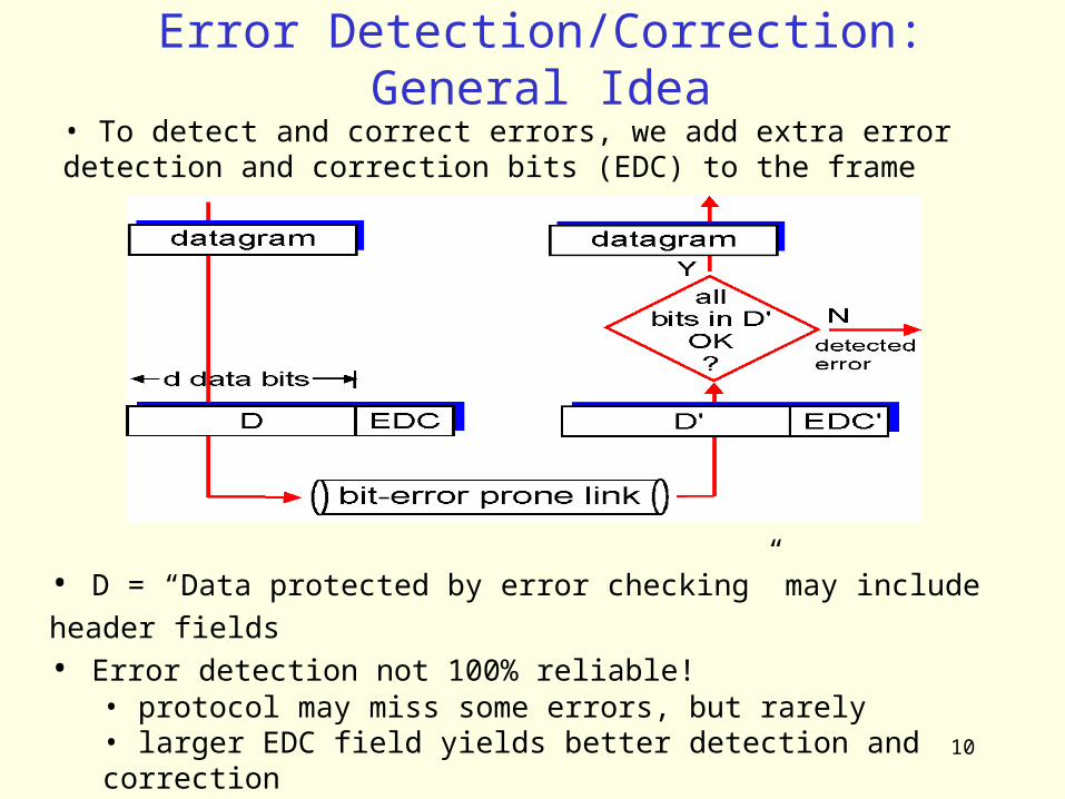
Error Detection/Correction: General Idea• To detect and correct errors, we add extra error detection and correction bits (EDC) to the frame
• D = “Data protected by error checking” may include header fields • Error detection not 100% reliable!
• protocol may miss some errors, but rarely• larger EDC field yields better detection and correction
11
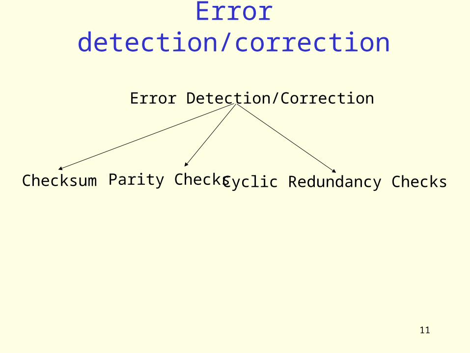
Error detection/correction
Error Detection/Correction
Parity Checks Cyclic Redundancy ChecksChecksum

12
ChecksumsSender:• treat segment
contents as sequence of 16-bit integers
• checksum: addition (1’s complement sum) of segment contents
Receiver:• compute checksum of
received segment• check if computed checksum
equals checksum field value:– NO: error detected– YES: no error detected.
But maybe errors nonetheless?
• Mis-ordered words
• Why use checksum?• simple to implement in software• Typically used by upper layer protocols: TCP, UDP, IP..• Found to be enough in ARPANET by experience
13
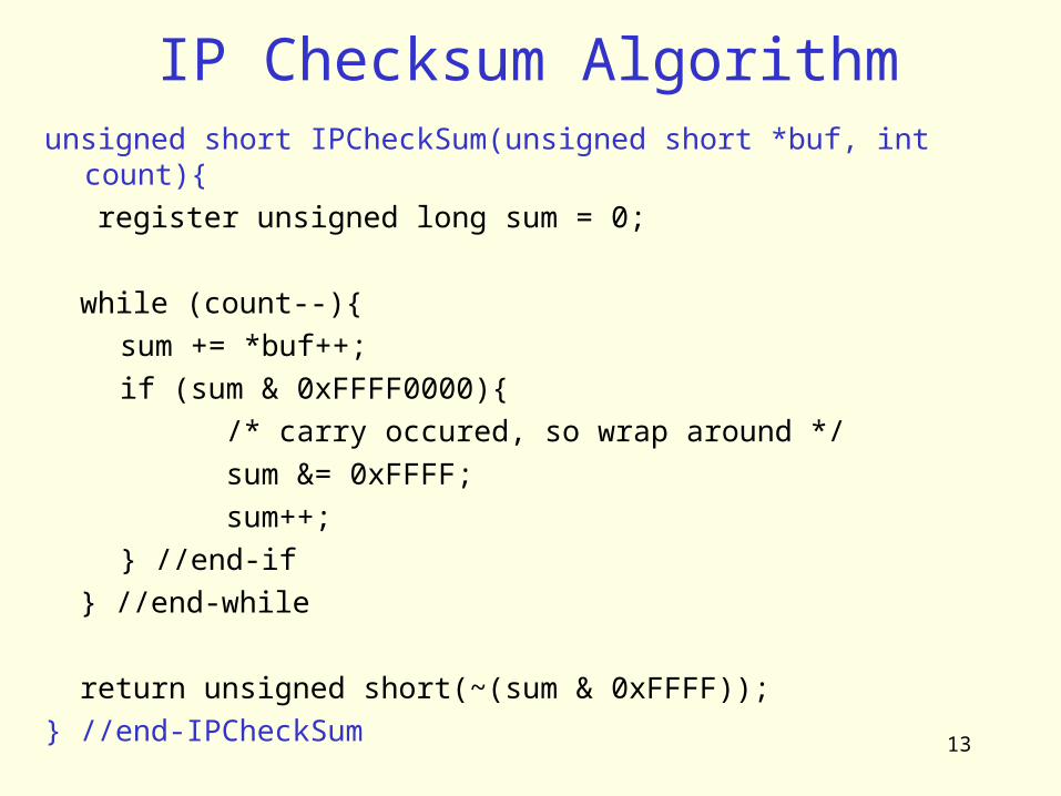
IP Checksum Algorithmunsigned short IPCheckSum(unsigned short *buf, int count){ register unsigned long sum = 0; while (count--){
sum += *buf++; if (sum & 0xFFFF0000){
/* carry occured, so wrap around */ sum &= 0xFFFF; sum++;
} //end-if } //end-while
return unsigned short(~(sum & 0xFFFF));} //end-IPCheckSum
14
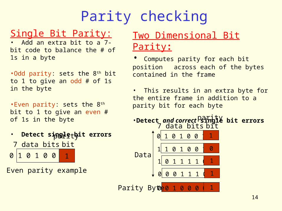
Parity checkingSingle Bit Parity:• Add an extra bit to a 7-bit code to balance the # of 1s in a byte
•Odd parity: sets the 8th bit to 1 to give an odd # of 1s in the byte
•Even parity: sets the 8th bit to 1 to give an even # of 1s in the byte
• Detect single bit errors
Two Dimensional Bit Parity:• Computes parity for each bit position across each of the bytes contained in the frame
• This results in an extra byte for the entire frame in addition to a parity bit for each byte
•Detect and correct single bit errors
0 1 0 1 0 0 1 1
7 data bitsparity
bit
Even parity example
0 1 0 1 0 0 1 1
7 data bitsparity
bit
1 1 0 1 0 0 1 0
1 0 1 1 1 1 0 1
0 0 0 1 1 1 0 1
0 0 1 0 0 0 0 1Parity Byte
Data

15
Two-Dimensional Parity Checking
O O
16
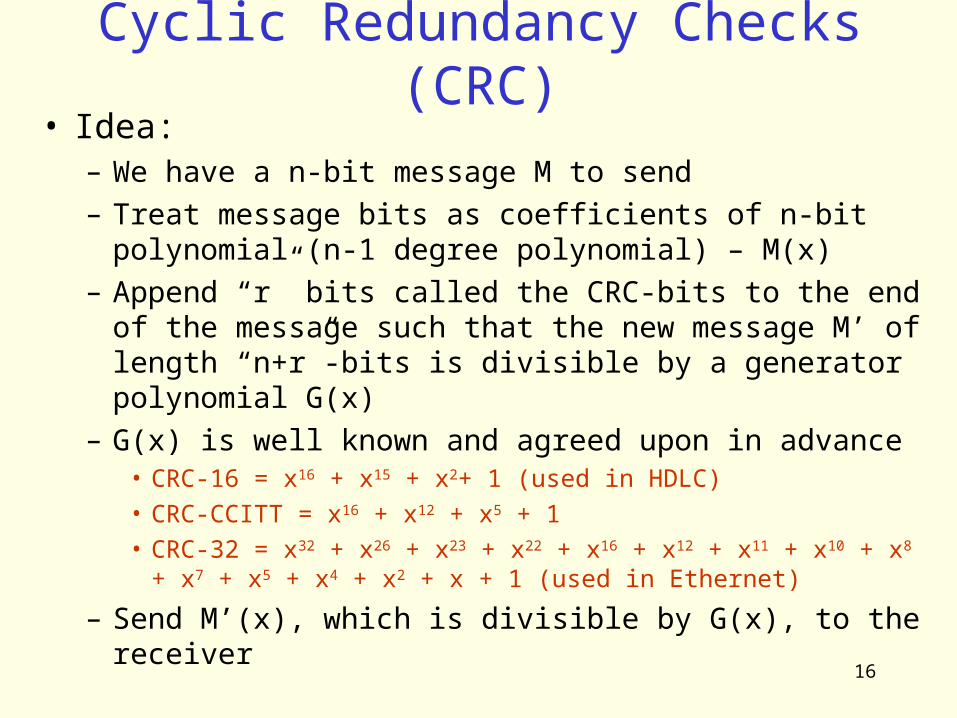
Cyclic Redundancy Checks (CRC)• Idea:
– We have a n-bit message M to send– Treat message bits as coefficients of n-bit
polynomial (n-1 degree polynomial) – M(x)– Append “r” bits called the CRC-bits to the end of
the message such that the new message M’ of length “n+r”-bits is divisible by a generator polynomial G(x)
– G(x) is well known and agreed upon in advance• CRC-16 = x16 + x15 + x2+ 1 (used in HDLC) • CRC-CCITT = x16 + x12 + x5 + 1 • CRC-32 = x32 + x26 + x23 + x22 + x16 + x12 + x11 + x10 + x8
+ x7 + x5 + x4 + x2 + x + 1 (used in Ethernet)
– Send M’(x), which is divisible by G(x), to the receiver
17
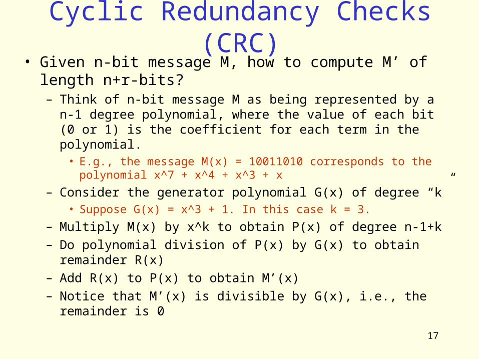
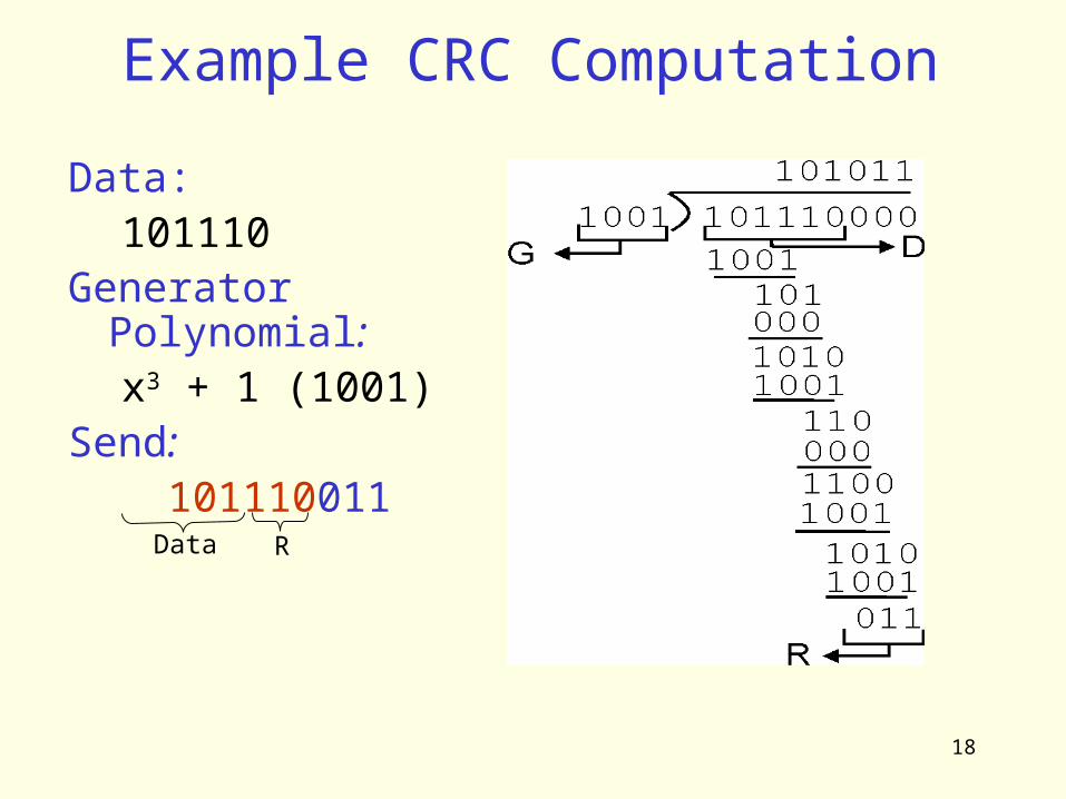
Cyclic Redundancy Checks (CRC)• Given n-bit message M, how to compute M’ of
length n+r-bits?– Think of n-bit message M as being represented by a n-1
degree polynomial, where the value of each bit (0 or 1) is the coefficient for each term in the polynomial.
• E.g., the message M(x) = 10011010 corresponds to the polynomial x^7 + x^4 + x^3 + x
– Consider the generator polynomial G(x) of degree “k”• Suppose G(x) = x^3 + 1. In this case k = 3.
– Multiply M(x) by x^k to obtain P(x) of degree n-1+k– Do polynomial division of P(x) by G(x) to obtain remainder
R(x)– Add R(x) to P(x) to obtain M’(x)– Notice that M’(x) is divisible by G(x), i.e., the remainder is
0
18
Example CRC Computation
Data:101110
Generator Polynomial:x3 + 1 (1001)
Send: 101110011
Data R
19
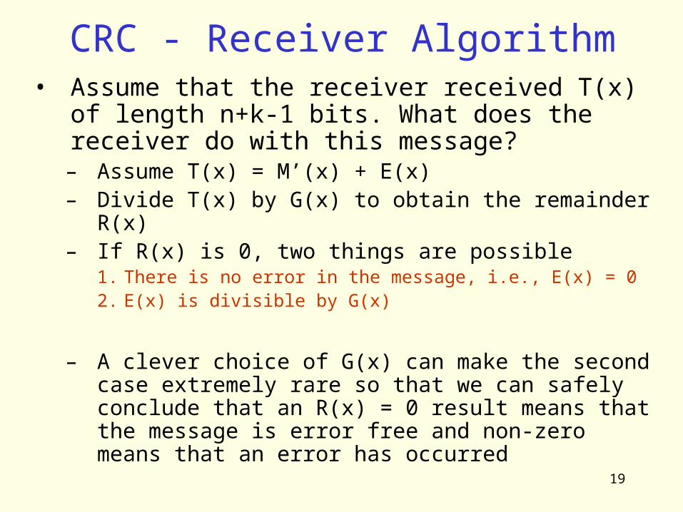
CRC - Receiver Algorithm• Assume that the receiver received T(x) of
length n+k-1 bits. What does the receiver do with this message?– Assume T(x) = M’(x) + E(x)– Divide T(x) by G(x) to obtain the remainder
R(x)– If R(x) is 0, two things are possible
1. There is no error in the message, i.e., E(x) = 02. E(x) is divisible by G(x)
– A clever choice of G(x) can make the second case extremely rare so that we can safely conclude that an R(x) = 0 result means that the message is error free and non-zero means that an error has occurred

20
Forward error correction• FEC
– Use error correcting codes to repair losses– Add redundant information which allows
receiver to correct bit errors– Requires knowledge at information and
coding theory and is out of the scope of this course

21
Framing• Up until now, we have added
LL header to the data and appended a EDC to the end to form a LL frame
• This frame will be transmitted to the destination (receiver)
• Problem: How would the receiver determine where the frame bits start and where they end as the adapter is receiving a sequence of bits from the link?– Called the framing problem– Idea: Add some extra framing
information before sending the frame
LL Frame
Datagram
DatagramH
DatagramH EDC
Add Framing Information
Encode Bits to the Link PL
LL
Link

22
Framing• Several solutions exist to solve the framing
problem. We will look at a few– Byte counting Approach – DDCMP
• Before sending the frame bits, send # of bytes in the frame first
– Sentinel Approach - BISYNC, IMP-IMP, HDLC, PPP• Denote the end (and maybe the beginning) of the frame
by a special char, called the sentinel char or flag• Q: What if the sentinel char appears in the data?
– Byte stuff the control chars– Bit stuff data sequence
– Physical Layer Coding Violations – Ethernet, 802 LANs
• Make use of physical layer. Use an encoding sequence that is not used for encoding data to mark the end of a frame
• Requires a dependence between LL & PL
23
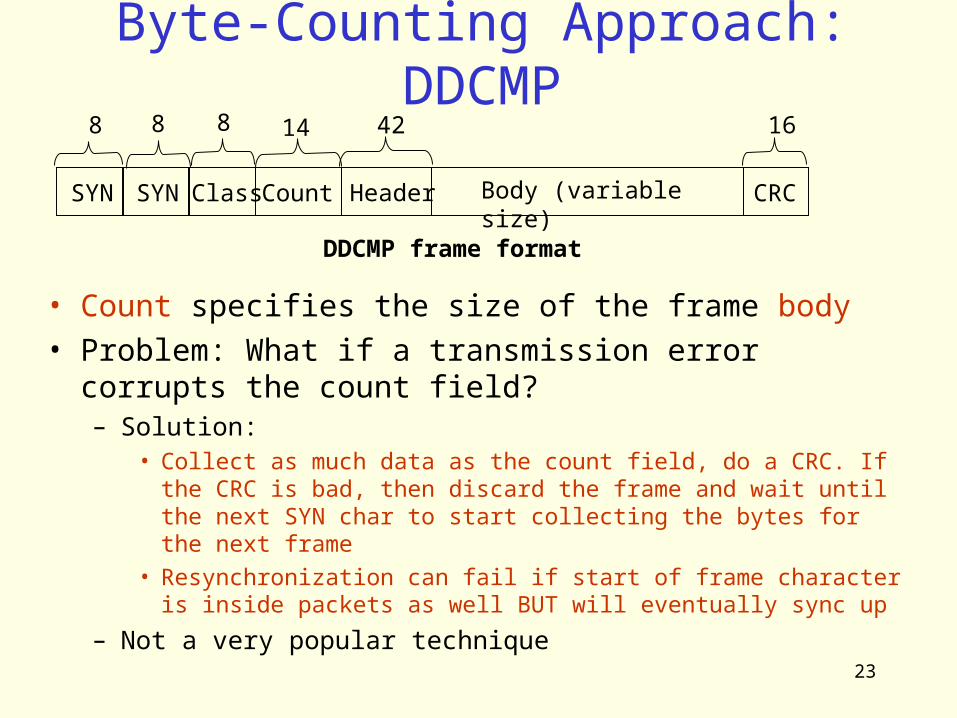
Byte-Counting Approach: DDCMP
SYN SYN ClassCount Header Body (variable size)
CRC
8 8 8 16
DDCMP frame format
• Count specifies the size of the frame body• Problem: What if a transmission error corrupts the
count field?– Solution:
• Collect as much data as the count field, do a CRC. If the CRC is bad, then discard the frame and wait until the next SYN char to start collecting the bytes for the next frame
• Resynchronization can fail if start of frame character is inside packets as well BUT will eventually sync up
– Not a very popular technique
4214
24
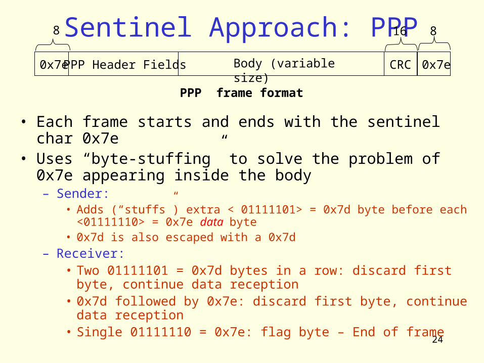
Sentinel Approach: PPP
• Each frame starts and ends with the sentinel char 0x7e
• Uses “byte-stuffing” to solve the problem of 0x7e appearing inside the body– Sender:
• Adds (“stuffs”) extra < 01111101> = 0x7d byte before each <01111110> = 0x7e data byte
• 0x7d is also escaped with a 0x7d– Receiver:
• Two 01111101 = 0x7d bytes in a row: discard first byte, continue data reception
• 0x7d followed by 0x7e: discard first byte, continue data reception
• Single 01111110 = 0x7e: flag byte – End of frame
0x7ePPP Header Fields Body (variable size)
0x7e
8 16 8
PPP frame format
CRC
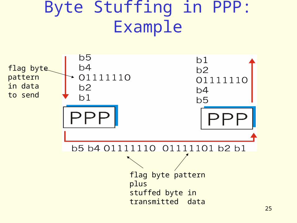
25
Byte Stuffing in PPP: Example
flag bytepatternin datato send
flag byte pattern plusstuffed byte in transmitted data
26
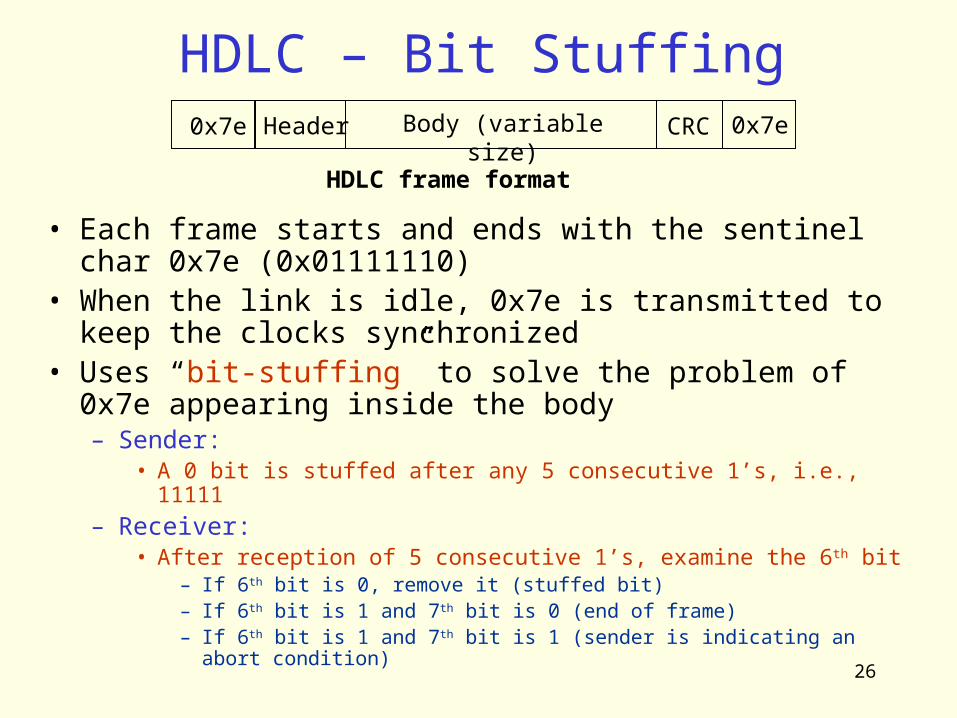
HDLC – Bit Stuffing0x7e Header Body (variable size) CRC
HDLC frame format
• Each frame starts and ends with the sentinel char 0x7e (0x01111110)
• When the link is idle, 0x7e is transmitted to keep the clocks synchronized
• Uses “bit-stuffing” to solve the problem of 0x7e appearing inside the body– Sender:
• A 0 bit is stuffed after any 5 consecutive 1’s, i.e., 11111– Receiver:
• After reception of 5 consecutive 1’s, examine the 6th bit– If 6th bit is 0, remove it (stuffed bit)– If 6th bit is 1 and 7th bit is 0 (end of frame)– If 6th bit is 1 and 7th bit is 1 (sender is indicating an abort
condition)
0x7e

27
Bit-Stuffing in HDLC:Example

28
Physical Layer Coding Violations• Make use of physical layer encoding scheme.
– Use an encoding sequence that is not used for encoding data to mark the end of a frame
• Only applicable to links in which the encoding on the physical medium contains some redundancy
• Used by Ethernet and IEEE 802 LANs
• No need for byte/bit stuffing (not even length field!)– More efficient use of link bandwidth
• But, requires a dependence between LL & PL– LL requires a specific PL to run.– That’s why Ethernet and IEEE LAN specs combine LL and
PL specs together
29
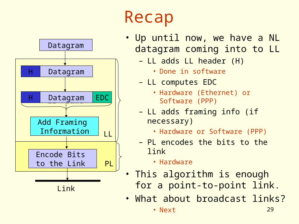
Recap• Up until now, we have a NL
datagram coming into to LL– LL adds LL header (H)
• Done in software
– LL computes EDC• Hardware (Ethernet) or Software
(PPP)
– LL adds framing info (if necessary)
• Hardware or Software (PPP)
– PL encodes the bits to the link• Hardware
• This algorithm is enough for a point-to-point link.
• What about broadcast links?• Next
LL Frame
Datagram
DatagramH
DatagramH EDC
Add Framing Information
Encode Bits to the Link PL
LL
Link
Related Documents