2 1. GENERAL PURPOSE CONTACTORS & STARTERS 1.1 Conformity to International Standards Series MS-N Mitsubishi magnetic motor starters and contactors are designed to conform to the relevant IEC recommendations and to the standards of as many countries as possible. Specifically, they conform to the following: VDE0660 NEMA-ICS IEC60947-4-1 EN60947-4-1 International Europe Germany U.S.A Table 1.1 DC Operated Contactor Overload Relay AC Operated Contactor Type (✽2) Canada U.K. France Korea Japan Lloyd’s Register of Shipping Korean Register of Shipping Bureau Veritas Nippon Kaiji Kyokai AC Operated Contactor Relay DC Operated Contactor Relay Auxiliary Contact Block U.S.A Canada U.S.A Listing Recognition Europe North America / UL TÜV CE Mark — — — — — ● (✽2) (✽2) ● (✽2) — — — ✩ — — — — — — — — — — — — — — Marine ( Mark) ( Mark) ( Mark) ( Mark) ( Mark) ( Mark) — (✽2) ✩ ( Mark) ( Mark) ( Mark) (✽2) Model Name SR-N4(CX) SRD-N4(CX) UN-AX2(CX) UN-AX4(CX) UN-AX11(CX) UN-AX80 UN-AX150 S-N10(CX) S-N11(CX)/N12(CX) S-N18(CX) S-N20(CX)/N21(CX) S-N25(CX) S-N35(CX) S-N28(CX) S-N38(CX) S-N48(CX) S-N50 S-N65 S-N80 S-N95 S-N125 S-N150 S-N180 S-N220 S-N300 S-N400 S-N600 S-N800 TH-N12(CX)KP TH-N18(CX)KP TH-N20(TA)(CX)KP TH-N60(TA)KP TH-N120(TA)KP TH-N220RHKP/HZKP TH-N400RHKP/HZKP SD-N11(CX)/N12(CX) SD-N21(CX) SD-N35(CX) SD-N50 SD-N65 SD-N80 SD-N95 SD-N125 SD-N150 SD-N220 SD-N300 SD-N400 SD-N600 SD-N800 China CCC certification — Notes:1. : CE Mark (Manufacturer’s Declaration) == Standard model applicable, marking on the product. UL, TÜV, CCC == Standard model applicable, marking on the product. NK == Standard model applicable, Certificate No. on the product. ● : Standard model applicable, no marking on the product. If marking required, order model name followed by suffix “DZ”. : Standard model applicable, no marking on the product. ✩ : Special model applicable, marking on the product. Order model name followed by suffix “UL”. ★ : China export applicable, no marking on the product. Ensure to add “CN” after the model name when placing an order. — : Not applicable to the Standard or not approved. 2. Finger protection type is certified according to DIN VDE 0106 part 100. For finger protection type, order model name followed by suffix “CX”. 3. For each certificate conditions, see next three pages. ★ ★ ★

Welcome message from author
This document is posted to help you gain knowledge. Please leave a comment to let me know what you think about it! Share it to your friends and learn new things together.
Transcript

2
1. GENERAL PURPOSE CONTACTORS & STARTERS1.1 Conformity to International Standards
Series MS-N
Mitsubishi magnetic motor starters and contactors are designed to conform to therelevant IEC recommendations and to the standards of as many countries aspossible. Specifically, they conform to the following:
VDE0660NEMA-ICS
IEC60947-4-1EN60947-4-1
InternationalEurope
GermanyU.S.A
Table 1.1
DCOperatedContactor
OverloadRelay
ACOperatedContactor
Type
(✽2)
Canada
U.K. France Korea Japan
Lloyd’sRegister ofShipping
KoreanRegister ofShipping
BureauVeritas
NipponKaiji
Kyokai
ACOperatedContactorRelayDCOperatedContactorRelay
AuxiliaryContactBlock
U.S.ACanadaU.S.A
Listing Recognition
Europe North America / UL
TÜVCE Mark
�
— — — — —
●
(✽2)
�
(✽2)
●
(✽2)
� — � ——
� �
� �
� �
✩
— —
� �
� �
� �
� �
— —
— —
— —
—
— —
—
�
——
�
Marine
( Mark)
( Mark)
( Mark)
( Mark)
( Mark)
( Mark)
—
�
(✽2)
✩
( Mark)
( Mark)
( Mark)
(✽2)
Model Name
SR-N4(CX)
SRD-N4(CX)
UN-AX2(CX)UN-AX4(CX)UN-AX11(CX)UN-AX80UN-AX150
S-N10(CX)S-N11(CX)/N12(CX)S-N18(CX)S-N20(CX)/N21(CX)S-N25(CX)S-N35(CX)S-N28(CX)S-N38(CX)S-N48(CX)S-N50S-N65S-N80S-N95S-N125S-N150S-N180S-N220S-N300S-N400S-N600S-N800TH-N12(CX)KPTH-N18(CX)KPTH-N20(TA)(CX)KPTH-N60(TA)KPTH-N120(TA)KPTH-N220RHKP/HZKPTH-N400RHKP/HZKPSD-N11(CX)/N12(CX)SD-N21(CX)SD-N35(CX)SD-N50SD-N65SD-N80SD-N95SD-N125SD-N150SD-N220SD-N300SD-N400SD-N600SD-N800
China
CCCcertification
—
Notes:1. : CE Mark (Manufacturer’s Declaration) == Standard model applicable, marking on the product.UL, TÜV, CCC == Standard model applicable, marking on the product.NK == Standard model applicable, Certificate No. on the product.
● : Standard model applicable, no marking on the product. If marking required, order model name followed by suffix “DZ”. � : Standard model applicable, no marking on the product. ✩ : Special model applicable, marking on the product. Order model name followed by suffix “UL”. ★ : China export applicable, no marking on the product. Ensure to add “CN” after the model name when placing an order. — : Not applicable to the Standard or not approved.2. Finger protection type is certified according to DIN VDE 0106 part 100. For finger protection type, order model name followed by suffix “CX”.3. For each certificate conditions, see next three pages.
★
★
★

3
Notes:1. Listed types are representatives and containes standard models.2. Applicable product standards
Contactors : EN60947-1, EN60947-4-1, EN60947-5-1Thermal overload relays : EN60947-1, EN60947-4-1, EN60947-5-1Aux. contact blocks : EN60947-1, EN60947-5-1Mechanical interlocks : EN60947-1, EN60947-4-1, EN60947-5-1
3. For mechanical interlocks, no marking on the product. Mechanical interlocks are applicable when used in reversing contactors.4. Necessary to connect a varistor etc., in order to provide compliance for CE marking for the US-N5/N8SS(TE)and US-N(H) 70/N(H)
80NS(TE) type.
1.1.1 List of Marked TypeStandard ContactorsNon-reversing
A.C. operated
D.C. operated
A.C. operated
D.C. operated
Additional Auxiliary Contact Blocks
Standard ContactorsReversing
Mechanical Interlocks3
S-N10, S-N11, S-N12, S-N18, S-N20, S-N21, S-N25, S-N28, S-N35, S-N38, S-N48, S-N50, S-N65, S-N80,S-N95, S-N125, S-N150, S-N180, S-N220, S-N300, S-N400, S-N600, S-N800
SD-N11, SD-N12, SD-N21, SD-N35, SD-N50, SD-N65, SD-N80, SD-N95, SD-N125, SD-N150, SD-N220,SD-N300, SD-N400, SD-N600, SD-N800
S-2XN10, S-2XN11, S-2XN20, S-2XN21, S-2XN25, S-2XN35, S-2XN50, S-2XN65, S-2XN80, S-2XN95,S-2XN125, S-2XN150, S-2XN180, S-2XN220, S-2XN300, S-2XN400, S-2XN600, S-2XN800
SD-2XN11, SD-2XN21, SD-2XN35, SD-2XN50, SD-2XN65, SD-2XN80, SD-2XN95, SD-2XN125, SD-2XN150,SD-2XN220, SD-2XN300, SD-2XN400, SD-2XN600, SD-2XN800
UN-AX2, UN-AX4, UN-AX11, UN-AX80, UN-AX150, UQ-AX2(KR)
UN-ML11, UN-ML21, UN-ML80, UN-ML150, UN-ML220
Thermal Overload Relays TH-N12KP, TH-N18KP, TH-N20KP, TH-N20TAKP, TH-N60KP, TH-N60TAKP, TH-N120KP, TH-N120TAKP,TH-N220RHKP, TH-N220HZKP, TH-N400RHKP, TH-N400HZKP, TH-N600KP
Contactor Relays A.C. operatedD.C. operated
D.C. Interface Contactors Non-reversingReversing
SR-N4SRD-N4SD-Q11, SD-Q12, SD-Q19SD-QR11, SD-QR12, SD-QR19
Table 1.1.1
Solid state Contactors (for motor/heater load)
Solid state Contactors (for heater load)
US-N5SS(TE), US-N8SS(TE), US-N20(TE), US-N30(TE), US-N40(TE), US-N50(TE), US-N70NS(TE), US-N80NS(TE),US-NH70NS(TE), US-NH80NS(TE), US-N20(TE)CX, US-N30(TE)CX, US-N40(TE)CX, US-N20(TE)RM
US-H20(DD), US-H30(DD), US-H40(DD), US-H50(DD), US-H20(DD)RM, US-H30(DD)RM
Notes:1. Standard models are applicable under following conditions.Main circuits : AC-3 rated current at 440V AC max.(Main contacts) and rated continuous current.Auxiliary contacts : AC-15 rated current at 550V AC max.
and rated continuous current.Operation coil : AC coil designation
N10~N12, N18~N48 and SR-N4 ; AC12V~AC440VN20~N35 ; AC12V~AC380VN50~N150 ; AC24V~AC500VN180~N400 ; AC48V~AC500VDC coil designation DC12V~DC220V
2. For contactors, standard models are with TÜV mark on the product.For other products, standard models are with no TÜV mark on the product.
3. Finger protection type is certified according to DIN VDE 0106 part 100. For finger protection type, order model name followed by suffix “CX”.4. Models with built-in surge absorber (model name followed by “SA”) are also certified.5. Mirror contact function compliance certification has been obtained from TÜV. This product is suitable for use in a machine tool's interlock circuit. The mirror
contact function refers to a function in which the auxiliary NC contact can withstand a 2500V impulse voltage without contacting even if the main contact melts.
1.1.2 TÜV Certified Type■ Contactor Table 1.1.2 (1)
S-N10(CX)(SA)S-N11(CX)(SA)S-N12(CX)(SA)S-N20(CX)(SA)S-N21(CX)(SA)S-N25(CX)(SA)S-N35(CX)(SA)S-N18(CX)(SA)S-N28(CX)(SA)S-N38(CX)(SA)S-N48(CX)(SA)S-N50/S-N65S-N80/S-N95S-N125S-N150S-N180/S-N220S-N300/S-N400SD-N11(CX)(SA)SD-N12(CX)(SA)SD-N21(CX)(SA)SD-N35(CX)(SA)SD-N50/SD-N65SD-N80/SD-N95SD-N125SD-N150SD-N220SD-N300/SD-N400
Model Name Certificate No.
EN60947-4-1 R9551340
Applicable standardMirror contact5
Internal auxiliary NC contactAuxiliary contact blockAuxiliary NC contact
EN60947-4-1
EN60947-4-1
EN60947-4-1EN60947-4-1EN60947-4-1EN60947-4-1EN60947-4-1EN60947-4-1
EN60947-4-1EN60947-4-1EN60947-4-1EN60947-4-1EN60947-4-1EN60947-4-1EN60947-4-1EN60947-4-1
EN60947-4-1
R9651190
R9651189
R9851170R9851138R9851169R9851167R9851164R9851171
R9551336R9651190R9851170R9851138R9851169R9851167R9851164R9851171
R9551340
�
—
�
�
�
�
�
�
—
—
�
(UN-AX2(CX), UN-AX4(CX))
� (UN-AX2(CX), UN-AX4(CX))
—
�
(UN-AX150)
�
(UN-AX2(CX), UN-AX4(CX))
�
(UN-AX150)
EN60947-4-1 R9551336
Solid state Contactors : EN60947-4-2, EN60947-4-3(for motor/heater load)Solid state Contactors : EN60947-4-3(for heater load)

4
Notes:1. Standard models are applicable under following conditions.Main circuits : AC-3 rated current at 440V AC max.(Main contacts) and rated continuous current.Auxiliary contacts : AC-15 rated current at 550V AC max. (SD-Q(R)11~Q(R)19 : 440V AC max.)
and rated continuous current.Operation coil : AC coil designation
SR-N4 ; AC12V~AC440VDC coil designation DC12V~DC220V (SD-Q(R)11~Q(R)19 : DC12V~DC24V)
2. For contactors, standard models are with TÜV mark on the product.For other products, standard models are with no TÜV mark on the product.For contactor relays, order model name followed by suffix “DZ” if TÜV mark on the product is required.
3. Finger protection type is certified according to DIN VDE 0106 part 100. For finger protection type, order model name followed bysuffix “CX”.
4. Models with built-in surge absorber (model name followed by “SA”) are also certified.5. Miller contact function compliance certification has been obtained from TÜV. This product is suitable for use in a machine tool's
interlock circuit. The miller contact function refers to a function in which the auxiliary NC contact can withstand a 2500V impulsevoltage without contacting even if the main contact melts.
6. If the SD-Q11 with 1NC is required, it must be so indicated when placing an order.
■ Thermal Overload Relay
TH-N12(CX)KP
TH-N18(CX)KP
TH-N20(TA)(CX)KP
TH-N60(TA)KP
TH-N120(TA)KP
TH-N220RHKP/HZKP
TH-N400RHKP/HZKP
Model Name Applicable standard Registration No.
EN60947-4-1
EN60947-4-1
EN60947-4-1
EN60947-4-1
EN60947-4-1
EN60947-4-1
EN60947-4-1
J9551338
J9551338
J9551341
J9851140
J9851168
J9851166
J9851172
Table 1.1.2 (3)■ DC Interface Contactor
SD-Q11
SD-Q12
SD-Q19
SD-QR11
SD-QR12
SD-QR19
Model Name Certificate No.Miller contact5
R2-50004919
R2-50004919
R2-50004918
R2-50004919
R2-50004919
R2-50004918
�
—
—
—
—
—
Table 1.1.2 (2)
Internal auxiliary NC contact Auxiliary contact blockAuxiliary NC contact
�
�
�
—
—
—
6 (UQ-AX2)
■ Contactor Relay
SR-N4(CX)(SA)
SRD-N4(CX)(SA)
Model Name Applicable standard Certificate No.
EN60947-5-1
EN60947-5-1
R9551339
R9551339
Table 1.1.2 (4) ■ Auxiliary Contact Block
UN-AX2(CX)
UN-AX4(CX)
UN-AX11(CX)
UN-AX80
UN-AX150
Model Name Applicable standard Registration No.
EN60947-5-1 J9551337
EN60947-5-1 R9851225
Table 1.1.2 (5)
■ Solid state contactor (for motor/heater lord) Table 1.1.2 (6)
Standard Finger protected Mounting on 35mm rail
Certificate No.
US-� US-�CX US-�RM
R50037627
R50037628
R50037629
R50037630
–
R50037628
–
–
R50037628
–
–
Model Name
US-N5SS(TE)
US-N8SS(TE)
US-N20(TE)
US-N30(TE)
US-N40(TE)
US-N50(TE)
US-N70NS(TE)
US-N80NS(TE)
US-NH70NS(TE)
US-NH80NS(TE)
Approval rating (A)
Heater (AC-51) Motor (AC-53)
AC100-240V AC200-440V AC200-240V AC400-440V
5
8
20
30
40
50(45)
70
80
–
–
3
4.8
12
18
24
30(27)
42
48
–
–
–
–
20
30
40
50(45)
–
–
65
75
–
–
12
18
24
30(27)
–
–
39
45
3.2
3.2
11.1
17.4
26
26
48
48
48
48
–
–
11.1
17.4
26
26
–
–
48
48
40C° 60C° 40C° 60C° 40C° 40C°
Applicable
standard
Motor:
EN60947-4-2
Heater:
EN60947-4-3
■ Solid state contactor (for heater lord) Table 1.1.2 (7)
Standard No cooling fin Mounting on 35mm rail
Certificate No.
US-� US-�HZ US-�RM
R50018958 R50018958
R50018958
–
Model Name
US-H20(DD)
US-H30(DD)
US-H40(DD)
US-H50(DD)
Approval rating (A)
Heater (AC-51)
AC24-480V
20
30
40
50
12
18
24
30
40C° 60C°
Applicable standard
Heater : EN60947-4-3
Notes: 1. The number in the type field indicates the certificate number, and hyphen “-” indicates that there are no compatible models.2. The value in the certified rating field in the bracket “( )” indicates the rating for US-N50TE.3. The frame field “(TE)” indicates 3-pole, 3-element type main circuit.4. Standard models are with TÜV mark on the product.
Notes: 1. The number in the type field indicates the certificate number, and hyphen “-” indicates that there are no compatible models.2. The frame field “(DD)” indicates 3-pole individual control.3. Standard models are with TÜV mark on the product.

5
S-N800UR2
910
——
250300600600
——
————
12004
–
S(D)-N11(CX)S(D)-N12(CX)
20
1/21-1/2
33
7-1/27-1/2
MSO-N11KP(CX)N12KP(CX)
33
7-1/27-1/2
30–
S-N10(CX)
13
1/21-1/2
3355
MSO-N10KP(CX)
3355
30–
A
120V HP240V HP
208V HP240V HP480V HP600V HP
208V HP240V HP480V HP600V HP
AA
Conta-ctor
(open)
Starter(open)
Max. rating of shortcircuit protection deviceFuse class K5Circuit breaker
S-N18(CX)
30
13
55
1010
MSO-N18KP(CX)
55
1010
70–
S-N20(CX)S(D)-N21(CX)
30
13
55
1010
MSO-N20KP(CX)N21KP(CX)
55
1010
70–
S-N25(CX)
35
23
7-1/27-1/2
1515
MSO-N25KP(CX)
7-1/27-1/2
1515
100100
S(D)-N35(CX)
40
25
10102020
MSO-N35KP(CX)
10102020
125125
S(D)-N50
80
37-1/2
15153030
MSO-N50KP
15153030
250—
S(D)-N65
95
310
15204040
MSO-N65KP
15204040
250—
S(D)-N80
100
515
20255050
MSO-N80KP
20255050
300300
S(D)-N1252
125
1020
40407575
MSO-N125KP 2
40407575
350350
S(D)-N952
100
7-1/215
25306060
MSO-N95KP 2
25306060
225225
S(D)-N1502
150
1525
4050100100
MSO-N150KP 2
4050100100
350350
S-N1802
220
1530
6060125125
MSO-N180KP 2
6060125125
500500
S(D)-N2202
220
1540
6075150150
MSO-N220KP 2
6075150150
500500
S(D)-N3002
300
——
100100200200
MSO-N300KP 2
100100200200
6003
600
S(D)-N4002
400
——
125150300300
MSO-N400KP 2
125150300300
5003
1000
S-N6002
680
——
150200400400
——
————
8004
–
Notes: 1. UL listed types for S-N600 and S-N800 require suffix letters “UL” (eg. S-N800UL).2. Types S-N95 to S-N800 and MSO-N95KP to N400KP with Ilsco lugs are also listed as type name with suffix letters “UL” (eg. S-N95UL)3. Time delay fuse4. Class L fuse
1.1.3 UL Approval for U.S.A. and Canada■ Contactor and Motor Starter
Model Name
Continuous current ratingopen
Horsepower ratingSingle phase
Three phase
Model Name
Horsepower ratingThree phase
Mark
Mark —
Table 1.1.3 (1)
Type Model Name MarkRatings
UN-AX2(CX)UN-AX4(CX)UN-AX11(CX)
UN-AX80UN-AX150
SR-N4SRD-N4
Contactor Relay
Auxiliary Contact Block
■ Contactor Relay and Auxiliary Contact Block Table 1.1.3 (3)
Rated Code;A600
AC600V max
Make 7200VA
Break 720VA
Rated Code;R300
DC250V max
Make 28VA
Break 28VA
■ Thermal Overload Relay Table 1.1.3 (2)
0.12A(0.1~0.16),0.17(0.14~0.22),0.24A(0.2~0.32),0.35A(0.28~0.42),0.5A(0.4~0.6),0.7A(0.55~0.85),0.9A(0.7~1.1),1.3A(1~1.6),1.7A(1.4~2),2.1A(1.7~2.5),2.5A(2~3),3.6A(2.8~4.4),5A(4~6),6.6A(5.2~8),9A(7~11),11A(9~13)
Model Name
TH-N12(CX)KP✩
TH-N12(CX)✩✽1TH-N12(CX)HZKP★✽2TH-N12(CX)HZ★✽1
TH-N18(CX)KP✩
TH-N18(CX)✩✽11.3A(1~1.6),1.7(1.4~2),2.1A(1.7~2.5),2.5A(2~3),3.6A(2.8~4.4),5A(4~6),6.6A(5.2~8),9A(7~11),11A(9~13),15A(12~18)
0.24A(0.2~0.32),0.35A(0.28~0.42),0.5A(0.4~0.6),0.7A(0.55~0.85),0.9A(0.7~1.1),1.3A(1~1.6),1.7A(1.4~2),2.1A(1.7~2.5),2.5A(2~3),3.6A(2.8~4.4),5A(4~6),6.6A(5.2~8),9A(7~11),11A(9~13),15A(12~18)
TH-N20(CX)KPTH-N20(CX)✽1TH-N20CXHZKP★
TH-N20CXHZ★✽1
TH-N20TAKP✩
TH-N20TA✩✽122A(18~26)29A(24~34)
TH-N60KP15A(12~18),22A(18~26),29A(24~34),35A(30~40),42A(34~50)54A(43~65)
TH-N60TAKP✩67A(54~80)82A(65~100)
TH-N120KP 42A(34~50),54A(43~65),67A(54~80),82A(65~100)105A(85~125)125A(100~150)82A(65~100),105A(85~125),125A(100~150),150A(120~180)180A(140~220)
TH-N220RHKP✩
TH-N220HZKP★
105A(85~125),125A(100~150),150A(120~180),180A(140~220),250A(200~300)330A(260~400)
TH-N400RHKP✩
TH-N400HZKP★
Heater designation (Rated current [A])Contactor tobe coupled
S-N10S-N11S-N12
S-N18
S-N20S-N21S-N25S-N35
S-N25,N35S-N35
S-N50,N65,N80,N95S-N65,N80,N95
S-N80,N95S-N95
S-N125,N150S-N125,N150
S-N150S-N180,N220
S-N220S-N300,N400
S-N400
Auxiliary Contact
RatedCode
Make
C600AC600Vmax
1800VA(15A max)
Break 180VA(1.5A max)
RatedCode
Make
B600AC600Vmax
3600VA(30A max)
Break 360VA(3A max)
/
/
TH-N120TAKP✩
Notes: 1. ✩ is to be coupled with contactor and can not be mounted separately from contactor. ★ is only for separate mounting.2. Suffix “KP” ; Overload and phase failure protection type with three heater elements.3. ✽1 ; TH-N12(CX), N12(CX)HZ, N18(CX), N20(CX), N20CXHZ and N20TA are recognized ( ) for single phase motors.4. ✽2 is to be coupled with TH-N12(CX)KP ( ) and UN-HZ12( ).

6
■ DC Interface ContactorTable 1.1.3 (4)
SD-Q11SD-Q12MSOD-Q11(KP)MSOD-Q12(KP)SD-Q19MSOD-Q19(KP)
Model Name Continuous
current rating [A]
Horsepower rating [HP]Single-phase (only non-reversing type) three-phase
Note: 1. MSOD-Q11, Q12 and Q19 are approved for single-phase circuits.
Non-reversing type Reversing typeSD-QR11SD-QR12MSOD-QR11KPMSOD-QR12KPSD-QR19MSOD-QR19KP
110 ~ 120V 220 ~ 240V 200 ~ 208V 220 ~ 240V 440 ~ 480V
20
13
3018
13
12
1 3 3 5
1 12
5 5 7 12
Model Name
US-N5SS
US-N8SS
US-N20(CX)(RM)
US-N30(CX)
US-N40(CX)
US-N50(CX)
US-N70NS
US-N80NS
US-NH70NS
US-NH80NS
US-N5SSTE
US-N8SSTE
US-N20TE(CX)(RM)
US-N30TE(CX)
US-N40TE(CX)
US-N50TE(CX)
US-N70NSTE
US-N80NSTE
US-NH70NSTE
US-NH80NSTE
1
2
2
3
3
3
3
15
15
15
15
3
53
3
3
–
–
5
10
20
20
–
–
30
30
5
8
20
30
40
50
70
80
70
80
100~120V 220~240V 220~240V 440~480V3-pole,2-element type 3-pole,3-element type
■ Solid state contactor (for motor/heater load) Table 1.1.3 (5)
Continuous current
rating [A]
110
110
12
1414
127
127
127
127
121
127
127
3434
Single-phase three-phase
Horsepower rating [HP]
US-H20(RM)(HZ)
US-H30(RM)
US-H40
US-H50
US-H20DD(RM)(HZ)
US-H30DD(RM)
US-H40DD
US-H50DD
20
30
40
50
■ Solid state contactor (for heater load) Table 1.1.3 (6)
Continuous current rating [A]
Model Name
Batch control Individual control
Notes: 1. “(HZ)” has no cooling fin. “(RM)” is available rail mounting.2. The US-H� (DD) HZ type is certified at the continuous current rating when combined with the fin used on the US-H� (DD) type.
3. The US-H� (DD) HZ type is UR certified.

7
1.1.4 CCC Certified ProductsMagnetic motor starters, etc., are designated as products targeted for China Compulsory Certification. CCC certification must be acquired before theproduct is exported to main land China from Domestic or marketed in China.The certified models are shown in Tables 1.1.4 (1-1) to 1.1.4 (8-2). The option units (UN-CV, ML, RR, SA, etc.) which are mounted on the magneticmotor starter and which do not have a load switching function are excluded from the CCC certification target.
Model Name
MSO-(2✕)N10✽✽
MSO(D)-(2✕)N11✽✽
MSO(D)-N12✽✽
MSO-(2✕)N18✽✽
MSO-(2✕)N20✽✽
MSO(D)-(2✕)N21✽✽
MSO-(2✕)N25✽✽
MSO(D)-(2✕)N35✽✽
MSO(D)-(2✕)N50KP✽✽
MSO(D)-(2✕)N65KP✽✽
MSO(D)-(2✕)N80KP✽✽
MSO(D)-(2✕)N95KP✽✽
MSO(D)-(2✕)N125KP✽✽
MSO(D)-(2✕)N150KP✽✽
MSO-(2✕)N180KP✽✽
MSO(D)-(2✕)N220KP✽✽
MSO(D)-(2✕)N300KP✽✽
MSO(D)-(2✕)N400KP✽✽
2.5/4
3.5/5.5
3.5/5.5
4.5/7.5
5.5/11
5.5/11
7.5/15
11/18.5
15/22
18.5/30
22/45
30/55
37/60
45/75
55/90
75/132
90/160
125/220
Approval rating AC-3 Class(200~240V/380~440V) Heater
designation
Coil designation
AC operated (MSO type)DC operated (MSOD type)Rated capacity (kW)
11/9
13/12
13/12
18/16
22/22
22/22
30/30
40/40
55/50
65/65
85/85
105/105
125/120
150/150
180/180
250/250
300/300
400/400
0.12-9A
0.12-11A
0.12-11A
0.12-15A
0.24-19A
0.24-19A
0.24-22A
0.24-35A
15-42A
15-54A
15-67A
15-95A
42-105A
42-125A
82-150A
82-210A
105-250A
105-330A
AC12V~AC500V
DC12V~DC220V
AC24V~AC500V
DC12V~DC220V
AC48V~AC500V
DC12V~DC220V
CX, KP, SA, SR
CX, SA
CX, KP, SA, SR
CX, SR
SR
Certificate No.Type ✽✽ application range
(combination possible)
Number of aux. contacts
Non-reversingStandard (special)
20020103 04093078
20020103 04093077
20020103 04093076
20020103 04093073
20020103 04093064
20020103 04093067
20020103 04093079
20020103 04093070
20020103 04093066
1NO(1NC)
1NO(1NC)
1NO1NC(2NO)
–
1NO1NC(2NO)
2NO2NC
2NO2NC
2NO2NC
2NO2NC
2NO2NC
2NO2NC
2NO2NC
2NO2NC
2NO2NC
2NO2NC
2NO2NC
2NO2NC
2NO2NC
Rated operational current (A)
MSO : AC operatedMSOD : DC operated2✕ : Reversing type
Table 1.1.4 (1-2)
Notes: 1. The MSO-(2×) N10KP, MSO(D)-(2×)N11KP or MSO(D)-N12KP type with heater designation 0.12A and 0.17A are not certified.2. MSO-(2×)N18KP type is not certified.
Model Name
MS-N10CN✽✽
MS-N11CN✽✽
MS-N12CN✽✽
MS-N20CN✽✽
MS-N21CN✽✽
MS-N25CN✽✽
MS-N35CN✽✽
MS-N50CNKP✽✽
MS-N65CNKP✽✽
MS-N80CNKP✽✽
MS-N95CNKP✽✽
MS-N125CNKP
MS-N150CNKP
MS-N180CNKP
MS-N220CNKP
MS-N300CNKP
MS-N400CNKP
2.5/4
3.5/5.5
3.5/5.5
5.5/11
5.5/11
7.5/15
11/18.5
15/22
18.5/30
22/45
30/55
37/60
45/75
55/90
75/132
90/160
125/220
Approval rating AC-3 Class(200~240V/380~440V)
Heaterdesignation
Coil designation
AC operatedRated capacity (kW)
11/9
13/12
13/12
22/22
22/22
30/30
40/40
55/50
65/65
85/85
105/105
125/120
150/150
180/180
250/250
300/300
400/400
0.12~9A
0.12~11A
0.12~11A
0.24~19A
0.24~19A
0.24~22A
0.24~35A
15~54A
15~54A
15~67A
15~95A
42~105A
42~125A
82~150A
82~210A
105~250A
105~330A
AC12V~AC500V
AC24V~AC500V
AC48V~AC500V
KP, SA, PM
KP, SA, PM
PM
–
Certificate No.Type ✽✽ application range
(combination possible)
Number of aux. contacts
Non-reversingStandard (special)
20030103 04093078
20030103 04093077
20030103 04093076
20030103 04093073
20030103 04093064
20030103 04093067
20030103 04093079
20030103 04093070
20030103 04093066
1NO
1NO
1NO1NC(2NO)
1NO1NC(2NO)
2NO2NC
2NO2NC
2NO2NC
2NO2NC
2NO2NC
2NO2NC
2NO2NC
2NO2NC
2NO2NC
2NO2NC
2NO2NC
2NO2NC
2NO2NC
Rated operational current (A)
■ Magnetic motor starter
MS : AC operated
Table 1.1.4 (1-1)• With Enclosure
• Without Enclosure
8
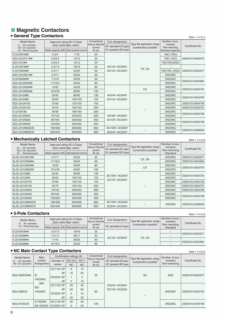
Model Name
S-(2✕)N10✽✽
S(D)-(2✕)N11✽✽
S(D)-N12✽✽
S-(2✕)N18✽✽
S-(2✕)N20✽✽
S(D)-(2✕)N21✽✽
S-(2✕)N25✽✽
S(D)-(2✕)N35✽✽
S(D)-(2✕)N50✽✽
S(D)-(2✕)N65✽✽
S(D)-(2✕)N80
S(D)-(2✕)N95
S(D)-(2✕)N125
S(D)-(2✕)N150 S-(2✕)N180
S(D)-(2✕)N220
S(D)-(2✕)N300
S(D)-(2✕)N400
S(D)-(2✕)N600CN
S(D)-(2✕)N800CN
2.5/4
3.5/5.5
3.5/5.5
4.5/7.5
5.5/11
5.5/11
7.5/15
11/18.5
15/22
18.5/30
22/45
30/55
37/60
45/75
55/90
75/132
90/160
125/220
190/330
220/440
Approval rating AC-3 Class(200~240V/380~440V)
Conventional free air thermal
currentIth (A)
Coil designation
AC operated (S type)DC operated (SD type)Rated capacity (kW)
11/9
13/12
13/12
18/16
22/22
22/22
30/30
40/40
55/50
65/65
85/85
105/105
125/120
150/150
180/180
250/250
300/300
400/400
630/630
800/800
20
20
20
25
32
32
50
60
80
100
135
150
150
200
260
260
350
450
660
800
AC12V~AC500V
DC12V~DC220V
AC24V~AC500V
DC12V~DC220V
AC48V~AC500V
DC12V~DC220V
AC100V~AC500V
DC24V~DC220V
CX, SA
CX
–
–
Certificate No.Type ✽✽ application range
(combination possible)
Number of aux. contacts
Non-reversingStandard (special)
20020103 04023375
20020103 04023377
20020103 04024684
20020103 04024704
20020103 04024705
20020103 04024706
20020103 04024707
20020103 04024708
20020103 04024709
20030103 04095569
1NO (1NC)
1NO (1NC)
1NO1NC(2NO)
–
1NO1NC (2NO)
2NO2NC
2NO2NC
2NO2NC
2NO2NC
2NO2NC
2NO2NC
2NO2NC
2NO2NC
2NO2NC
2NO2NC
2NO2NC
2NO2NC
2NO2NC
2NO2NC
2NO2NC
Rated operational current (A)
■ Magnetic Contactors
S : AC operatedSD : DC operated2✕ : Reversing type
Table 1.1.4 (2-1)
Table 1.1.4 (2-2)
Model Name
SL(D)-(2✕)N21✽✽
SL(D)-(2✕)N35✽✽
SL(D)-(2✕)N50✽✽
SL(D)-(2✕)N65✽✽
SL(D)-(2✕)N80
SL(D)-(2✕)N95
SL(D)-(2✕)N125
SL(D)-(2✕)N150
SL(D)-(2✕)N220
SL(D)-(2✕)N300
SL(D)-(2✕)N400
SL(D)-(2✕)N600CN
SL(D)-(2✕)N800CN
5.5/11
11/18.5
15/22
18.5/30
22/45
30/55
37/60
45/75
75/132
90/160
125/220
190/330
220/440
Approval rating AC-3 Class(200~240V/380~440V)
Conventional free air thermal
currentIth (A)
Coil designation
AC operated (SL type)DC operated (SLD type)Rated capacity (kW)
22/22
40/40
55/50
65/65
85/85
105/105
125/120
150/150
250/250
300/300
400/400
630/630
800/800
32
60
80
100
135
150
150
200
260
350
450
660
800
AC100V~AC500V
DC12V~DC200V
AC100V~AC500V
DC24V~DC200V
CX, SA
CX
–
–
Certificate No.Type ✽✽ application range
(combination possible)
Number of aux. contacts
Non-reversingStandard
20020103 04023377
20020103 04024684
20020103 04024704
20020103 04024705
20020103 04024706
20020103 04024707
20020103 04024708
20020103 04024709
20030103 04095569
2NO2NC
2NO2NC
2NO2NC
2NO2NC
2NO2NC
2NO2NC
2NO2NC
2NO2NC
2NO2NC
2NO2NC
2NO2NC
1NO2NC
Rated operational current (A)
SL : AC operatedSLD : DC operated2✕ : Reversing type
Table 1.1.4 (2-3)
Model Name
S-(2✕)N18✽✽
S-(2✕)N28✽✽
S-(2✕)N38✽✽
S-(2✕)N48✽✽
4.5/7.5
7.5/7.5
11/15
15/18.5
Approval rating AC-3 Class(200~240V/380~440V)
Conventional free air thermal
currentIth (A)
Coil designation
AC operated (S type)Rated capacity (kW)
18/16
26/17
39/32
50/40
25
30
60
80
AC12V~AC500V CX, SA
Certificate No.Type ✽✽ application range
(combination possible)
Number of aux. contacts
Non-reversingStandard
20020103 04023377
20020103 04024684
–
–
–
–
Rated operational current (A)
S : AC operated2✕ : Reversing type
Model Name
B(D)-N20CN✽✽
B(D)-N65CN
B(D)-N100CN
DC110V 2P
3P
DC220V 2P
3P
DC110V 2P
3P
DC220V 2P
3P
DC110V 2P
DC220V 2P
B:
1NO2NC,
3NC
BD:
1NO2NC
B:1NO2NC
BD:1NO2NC
Certification ratings (A)Maincontact
Arrangement
Conventional free air thermal
currentIth (A)
Coil designation
AC operated (B type)DC operated (BD type)
Number ofseries
8
15
1
5
20
50
3
20
30
3
25
80
120
AC24V~AC500V
DC12V~DC220V
SA
–
Number of aux. contacts
Non-reversing
20020103 04023377
20020103 04024705
20020103 04024706
2NO
2NO2NC
2NO2NC
NC
DC-3,5
15
20
5
10
30
65
10
30
40
20
NC
DC-1B : AC operatedBD : DC operated
Table 1.1.4 (2-4)
Certificate No.Type ✽✽ application range
(combination possible)
• General Type Contactors
• Mechanically Latched Contactors
• 3-Pole Contactors
• NC Main Contact Type Contactors

9
20020103 03024700
20020103 03024720
20020103 03024722
20020103 03024720
Model Name Certificate No.
UN-AX2CN✽✽
UN-AX4CN✽✽
UN-AX11CN✽✽
UN-AX80CN
UN-AX150CN
UN-AX600CN
UN-LL22CN✽✽
2NO, 1NO1NC
4NO, 3NO1NC, 2NO2NC
1NO1NC
1NO1NC
1NO1NC
2NO2NC
1NO1NC(low level), 1NO1NC(standard)
Available contact arrangements
CX
–
CX
S-N10~N65
S-N10, N11, N20~N65
S-N80~N125
S-N150~N400
S-N600, N800
S-N10~N65, SR-N4
Type ✽✽ application range(combination possible)
Applicable magnetic contactor
■ Auxiliary contact block Table 1.1.4 (4)
Note: 1. The TH-N12KP✽✽ type with heater designation 0.12A and 0.17A, and the TH-N18KP✽✽ type are not certified.Note: 2. Heater designation 210A are certified for S-N220 type.
20020103 09024710
20020103 09024712
20020103 09024714
20020103 09024724
20020103 09024719
20030103 04095454
Model Name Certificate No.
TH-N12KP✽✽
TH-N20KP✽✽
TH-N20TAKP✽✽
TH-N60KP✽✽
TH-N60TAKP✽✽
TH-N120KP✽✽
TH-N120TAKP✽✽
TH-N220RHKP✽✽
TH-N220HZKP✽✽
TH-N400RHKP✽✽
TH-N400HZKP✽✽
TH-N600KP✽✽
0.24A, 0.35A, 0.5A, 0.7A, 0.9A, 1.3A, 1.7A, 2.1A, 2.5A,
3.6A, 5A, 6.6A, 9A, 11A
0.24A, 0.35A, 0.5A, 0.7A, 0.9A, 1.3A, 1.7A, 2.1A, 2.5A,
3.6A, 5A, 6.6A, 9A, 11A, 15A
22A, 29A
15A, 22A, 29A, 35A, 42A, 54A
67A, 82A
42A, 54A, 67A, 82A
105A, 125A
82A, 105A, 125A, 150A, 180A, 210A2
105A, 125A, 150A, 180A, 250A, 330A
250A, 330A, 500A, 660A
Heater designation
CX, HZ
CX, HZ, SR
CX, SR
CX, SR
SR
HZ, SR
SR
SR
S-N10~N12
S-N20~N35
S-N25, N35
S-N50~N95
S-N80, N95
S-N125, N150
S-N180, N220
S-N300, N400
Type ✽✽ application range (combination possible)
Combination magnetic contactor
■ Thermal overload relay
Dedicated for independent mounting
Dedicated for independent mounting
Dedicated for independent mounting
Table 1.1.4 (3-1)• Three heater type with phase failure protection
Model Name
SD-Q11
SD-Q12
SD-Q19
SD-QR11
SD-QR12
SD-QR19
3/4
4.5/5.5
3/4
4.5/5.5
Approval rating AC-3 Class(200~240V/380~440V)
Conventional free air thermal
currentIth (A)
Coil designation
DC operationRated capacity (kW)
12/9
18/13
12/9
18/13
20
30
20
30
DC24V
DC24V
Certificate No.Number of aux. contacts
Standard (special)
20030103 04095567
20030103 04086213
20030103 04095567
20030103 04086213
1NO(1NC)
1NO1NC(2NO)
1NO1NC(2NO)
2NC
2NO2NC
2NO2NC
Rated operational current (A)
Q : Non-reversing typeQR : Reversing type
Table 1.1.4 (5-2)• Magnetic contactor
• Magnetic motor starter
Note: 1. Heater designation 0.12A and 0.17A are not certified for MSOD-Q11KP and Q12KP types.
Model Name
MSOD-Q11✽✽
MSOD-Q12✽✽
MSOD-Q19✽✽
MSOD-QR11✽✽
MSOD-QR12✽✽
MSOD-QR19✽✽
3/4
4.5/5.5
3/4
4.5/5.5
Approval rating AC-3 Class(200~240V/380~440V)
Heaterdesignation
Coil designation
DC operationRated capacity (kW)
12/9
18/13
12/9
18/13
0.12~11A
1.3~15A
0.12~11A
1.3~15A
DC24V
DC24V
CX, KP
CX
CX, KP
CX
Certificate No.Type ✽✽ application range
(combination possible)
Number of aux. contacts
Standard (special)
20030103 04093069
20030103 04093080
20030103 04093069
20030103 04093080
1NO(1NC)
1NO1NC(2NO)
1NO1NC(2NO)
2NC
2NO2NC
2NO2NC
Rated operational current (A)
■ DC interface contactor
Q : Non-reversing typeQR : Reversing type
Table 1.1.4 (5-1)
20020103 09024701
20020103 09024702
20020103 09024703
Model Name Certificate No.
TH-N12✽✽
TH-N18✽✽
TH-N20✽✽
TH-N20TA✽✽
0.12A, 0.17A, 0.24A, 0.35A, 0.5A, 0.7A, 0.9A, 1.3A, 1.7A, 2.1A, 2.5A, 3.6A, 5A, 6.6A, 9A, 11A
1.3A, 1.7A, 2.1A, 2.5A, 3.6A, 5A, 6.6A, 9A, 11A, 15A
0.24A, 0.35A, 0.5A, 0.7A, 0.9A, 1.3A, 1.7A, 2.1A, 2.5A, 3.6A, 5A, 6.6A, 9A, 11A, 15A
22A, 29A, 35A1
Heater designation
CX, HZ, SR
CX, DM
CX, HZ, SR
CX, SR
S-N10~N12
S-N18
S-N20~N35
S-N25, N35
Type ✽✽ application range (combination possible)
Combination magnetic contactor
Table 1.1.4 (3-2)• Two heater type
Note: 1. Heater designation 35A are certified for S-N35 type.
10
Model Name
SR-N4✽✽
SRD-N4✽✽
SRL-N4✽✽
SRLD-N4✽✽
Coil designation
AC operated (SR, SRL type)DC operated (SRD, SRLD type)
AC12V~AC440VDC12V~DC220VAC100V~AC440VDC12V~DC200V
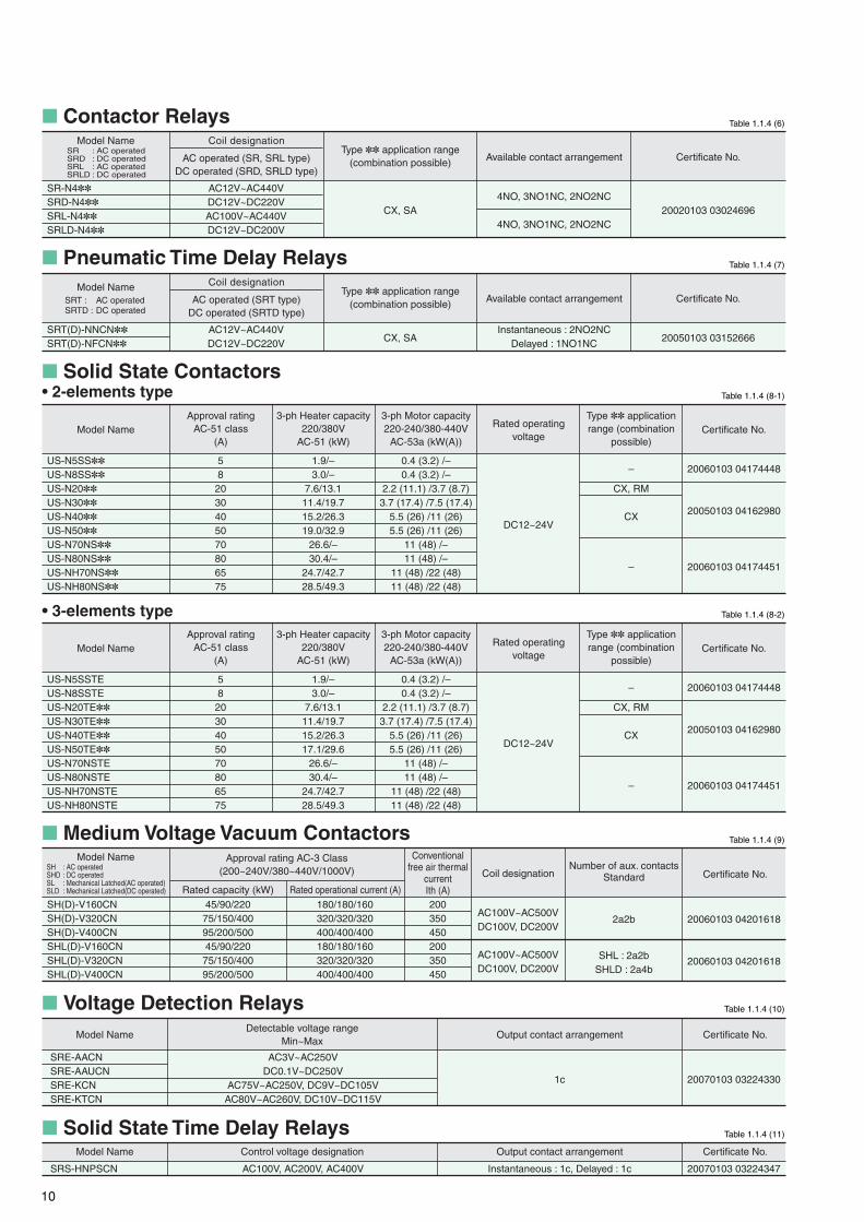
4NO, 3NO1NC, 2NO2NC
4NO, 3NO1NC, 2NO2NCCX, SA
Certificate No.Available contact arrangementType ✽✽ application range
(combination possible)
20020103 03024696
■ Contactor Relays
SR : AC operatedSRD : DC operatedSRL : AC operatedSRLD : DC operated
Table 1.1.4 (6)
SRT(D)-NNCN✽✽
SRT(D)-NFCN✽✽
Coil designation
AC operated (SRT type)DC operated (SRTD type)
AC12V~AC440VDC12V~DC220V
Instantaneous : 2NO2NCDelayed : 1NO1NCCX, SA
Certificate No.Available contact arrangementType ✽✽ application range
(combination possible)
20050103 03152666
■ Pneumatic Time Delay Relays Table 1.1.4 (7)
Model NameSRT : AC operatedSRTD : DC operated
■ Solid State ContactorsTable 1.1.4 (8-1)
US-N5SS✽✽
US-N8SS✽✽
US-N20✽✽
US-N30✽✽
US-N40✽✽
US-N50✽✽
US-N70NS✽✽
US-N80NS✽✽
US-NH70NS✽✽
US-NH80NS✽✽
582030405070806575
DC12~24V
0.4 (3.2) /–0.4 (3.2) /–
2.2 (11.1) /3.7 (8.7)3.7 (17.4) /7.5 (17.4)
5.5 (26) /11 (26)5.5 (26) /11 (26)
11 (48) /–11 (48) /–
11 (48) /22 (48)11 (48) /22 (48)
–
CX, RM
CX
–
Certificate No.Approval rating
AC-51 class(A)
1.9/–3.0/–
7.6/13.111.4/19.715.2/26.319.0/32.9
26.6/–30.4/–
24.7/42.728.5/49.3
3-ph Heater capacity220/380V
AC-51 (kW)
3-ph Motor capacity220-240/380-440V
AC-53a (kW(A))
Rated operatingvoltage
Type ✽✽ application range (combination
possible)
20060103 04174448
20050103 04162980
20060103 04174451
Model Name
• 2-elements type
Table 1.1.4 (8-2)
US-N5SSTEUS-N8SSTEUS-N20TE✽✽
US-N30TE✽✽
US-N40TE✽✽
US-N50TE✽✽
US-N70NSTEUS-N80NSTEUS-NH70NSTEUS-NH80NSTE
582030405070806575
DC12~24V
0.4 (3.2) /–0.4 (3.2) /–
2.2 (11.1) /3.7 (8.7)3.7 (17.4) /7.5 (17.4)
5.5 (26) /11 (26)5.5 (26) /11 (26)
11 (48) /–11 (48) /–
11 (48) /22 (48)11 (48) /22 (48)
–
CX, RM
CX
–
Certificate No.Approval rating
AC-51 class(A)
1.9/–3.0/–
7.6/13.111.4/19.715.2/26.317.1/29.6
26.6/–30.4/–
24.7/42.728.5/49.3
3-ph Heater capacity220/380V
AC-51 (kW)
3-ph Motor capacity220-240/380-440V
AC-53a (kW(A))
Rated operatingvoltage
Type ✽✽ application range (combination
possible)
20060103 04174448
20050103 04162980
20060103 04174451
Model Name
• 3-elements type
Model Name
SH(D)-V160CNSH(D)-V320CNSH(D)-V400CNSHL(D)-V160CNSHL(D)-V320CNSHL(D)-V400CN
SH : AC operatedSHD : DC operatedSL : Mechanical Latched(AC operated)SLD : Mechanical Latched(DC operated)
Conventional free air thermal
currentIth (A)200350450200350450
Coil designation
AC100V~AC500VDC100V, DC200V
AC100V~AC500VDC100V, DC200V
Certificate No.Number of aux. contacts
Standard
20060103 04201618
20060103 04201618
2a2b
SHL : 2a2bSHLD : 2a4b
45/90/22075/150/40095/200/50045/90/22075/150/40095/200/500
Approval rating AC-3 Class(200~240V/380~440V/1000V)
Rated capacity (kW)180/180/160320/320/320400/400/400180/180/160320/320/320400/400/400
Rated operational current (A)
■ Medium Voltage Vacuum Contactors
20070103 03224330
Model Name Certificate No.
SRE-AACNSRE-AAUCNSRE-KCNSRE-KTCN
AC3V~AC250VDC0.1V~DC250V
AC75V~AC250V, DC9V~DC105VAC80V~AC260V, DC10V~DC115V
Detectable voltage rangeMin~Max
1c
Output contact arrangement
■ Voltage Detection Relays
20070103 03224347
Model Name Certificate No.
SRS-HNPSCN AC100V, AC200V, AC400V
Control voltage designation
Instantaneous : 1c, Delayed : 1c
Output contact arrangement
■ Solid State Time Delay Relays
Table 1.1.4 (9)
Table 1.1.4 (10)
Table 1.1.4 (11)
11
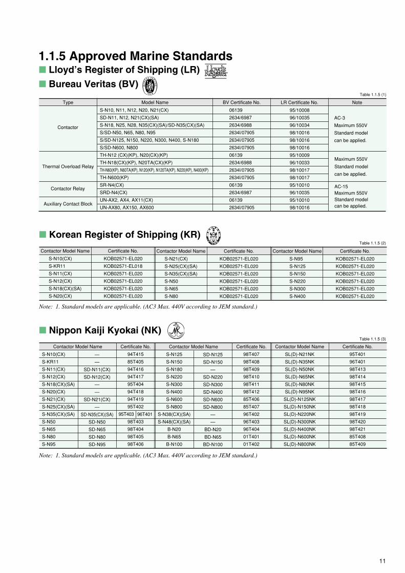
■ Lloyd’s Register of Shipping (LR)
■ Bureau Veritas (BV)
S-N10, N11, N12, N20, N21(CX)
SD-N11, N12, N21(CX)(SA)
S-N18, N25, N28, N35(CX)(SA)/SD-N35(CX)(SA)
S/SD-N50, N65, N80, N95
S/SD-N125, N150, N220, N300, N400, S-N180
S/SD-N600, N800
TH-N12 (CX)(KP), N20(CX)(KP)
TH-N18(CX)(KP), N20TA(CX)(KP)
TH-N60(KP), N60TA(KP), N120(KP), N120TA(KP), N220(KP), N400(KP)
TH-N600(KP)
SR-N4(CX)
SRD-N4(CX)
UN-AX2, AX4, AX11(CX)
UN-AX80, AX150, AX600
Type BV Certificate No.
06139
2634/6987
2634/6988
2634I/07905
2634I/07905
2634I/07905
06139
2634/6988
2634I/07905
2634I/07905
06139
2634/6987
06139
2634I/07905
Model Name
Contactor
Thermal Overload Relay
Contactor Relay
Auxiliary Contact Block
LR Certificate No.
95/10008
96/10035
96/10034
98/10016
98/10016
98/10016
95/10009
96/10033
98/10017
98/10017
95/10010
96/10035
95/10010
98/10016
Note
AC-3
Maximum 550V
Standard model
can be applied.
Maximum 550V
Standard model
can be applied.
AC-15Maximum 550VStandard modelcan be applied.
■ Korean Register of Shipping (KR)
KOB02571-EL020
KOB02571-EL018
KOB02571-EL020
KOB02571-EL020
KOB02571-EL020
KOB02571-EL020
Contactor Model Name Certificate No.
Note: 1. Standard models are applicable. (AC3 Max. 440V according to JEM standard.)
S-N10(CX)
S-KR11
S-N11(CX)
S-N12(CX)
S-N18(CX)(SA)
S-N20(CX)
KOB02571-EL020
KOB02571-EL020
KOB02571-EL020
KOB02571-EL020
KOB02571-EL020
KOB02571-EL020
Contactor Model Name Certificate No.
S-N21(CX)
S-N25(CX)(SA)
S-N35(CX)(SA)
S-N50
S-N65
S-N80
KOB02571-EL020
KOB02571-EL020
KOB02571-EL020
KOB02571-EL020
KOB02571-EL020
KOB02571-EL020
Contactor Model Name Certificate No.
S-N95
S-N125
S-N150
S-N220
S-N300
S-N400
■ Nippon Kaiji Kyokai (NK)
Contactor Model Name Certificate No.
Note: 1. Standard models are applicable. (AC3 Max. 440V according to JEM standard.)
S-N10(CX)
S-KR11
S-N11(CX)
S-N12(CX)
S-N18(CX)(SA)
S-N20(CX)
S-N21(CX)
S-N25(CX)(SA)
S-N35(CX)(SA)
S-N50
S-N65
S-N80
S-N95
—
—
SD-N11(CX)
SD-N12(CX)
—
—
SD-N21(CX)
—
SD-N35(CX)(SA)
SD-N50
SD-N65
SD-N80
SD-N95
94T415
85T405
94T416
94T417
95T404
94T418
94T419
95T402
98T403
98T404
98T405
98T406
95T403 96T401
Contactor Model Name Certificate No.
S-N125
S-N150
S-N180
S-N220
S-N300
S-N400
S-N600
S-N800
S-N38(CX)(SA)
S-N48(CX)(SA)
B-N20
B-N65
B-N100
SD-N125
SD-N150
—
SD-N220
SD-N300
SD-N400
SD-N600
SD-N800
—
—
BD-N20
BD-N65
BD-N100
98T407
98T408
98T409
98T410
98T411
98T412
85T406
85T407
96T402
96T403
96T404
01T401
01T402
Contactor Model Name Certificate No.
SL(D)-N21NK
SL(D)-N35NK
SL(D)-N50NK
SL(D)-N65NK
SL(D)-N80NK
SL(D)-N95NK
SL(D)-N125NK
SL(D)-N150NK
SL(D)-N220NK
SL(D)-N300NK
SL(D)-N400NK
SL(D)-N600NK
SL(D)-N800NK
95T401
96T401
98T413
98T414
98T415
98T416
98T417
98T418
98T419
98T420
98T421
85T408
85T409
1.1.5 Approved Marine Standards
Table 1.1.5 (1)
Table 1.1.5 (2)
Table 1.1.5 (3)

12
Three-phase motor
ratings IEC category
AC-3 kW(hp)
11(15)
18.5(25)
18.5(25)
15(20)
60
2NO+2NC
—
1
2
1
1
2.5(3-1/4)
4(5-1/2)
4(5-1/2)
4(5-1/2)
20
1NO
1NC
1
2
1
1
1.2 Selection Guide
220-240V
380-440V
500V
690V
1NO + 1NC (front)
1NO + 1NC (side)
2NO + 2NC (front)
Low level signal (front)
[1NO+1NC
(+Standard 1NO + 1NC)]
Conventional free air thermal current Ith A
Auxiliary contacts1 (standard)
(special)
3.5(4-1/2)
5.5(7-1/2)
5.5(7-1/2)
5.5(7-1/2)
20
1NO
1NC
1
2
1
1
3.5(4-1/2)
5.5(7-1/2)
5.5(7-1/2)
5.5(7-1/2)
20
1NO+1NC
2NO
1
—
1
1
4.5(6)
7.5(10)
7.5(10)
7.5(10)
25
–2
—
1
—
1
1
5.5(7-1/2)
11(15)
11(15)
7.5(10)
32
1NO+1NC
2NO
1
2
1
1
5.5(7-1/2)
11(15)
11(15)
7.5(10)
32
2NO+2NC
—
1
2
1
1
7.5(10)
15(20)
15(20)
11(15)
50
2NO+2NC
—
1
2
1
1
Notes: 1. Number of auxiliary contact shows that for non-reversing type. Twice of the auxiliary contacts are provided on reversing type.2. (2NO + 2NC) × 2 auxiliary contacts are provided on reversing type and no additional contact can be mounted.3. Front clip-on and side clip-on block should not be mounted both.
MS-N35
(KP)
MSO-N35
(KP)(CX)
S-N18(CX)
S-2xN18(CX)
—DC operated models
MS-N25
(KP)
MSO-N25
(KP)(CX)
S-N10(CX)
S-2xN10(CX)
—
Non-reversing
Reversing
S-N11(CX)
S-2xN11(CX)
SD-N11(CX)
S-N12(CX)
—
SD-N12(CX)
S-N20(CX)
S-2xN20(CX)
—
S-N21(CX)
S-2xN21(CX)
SD-N21(CX)
S-N25(CX)
S-2xN25(CX)
—
S-N35(CX)
S-2XxN35(CX)
SD-N35(CX)
AC operated models
MS-N10
(KP)
MSO-N10
(KP)(CX)
Enclosed type (IP20) MS-N11
(KP)
MSO-N11
(KP)(CX)
MS-N20
(KP)
MSO-N20
(KP)(CX)
MS-N21
(KP)
MSO-N21
(KP)(CX)Open type (IP00) MSO-N18
(KP)(CX)
—
Contactors
MS-N12
(KP)
MSO-N12
(KP)(CX)
Staters (AC operated)
Thermal Overload Relays1
0.2~0.32(0.24A)
0.28~0.42(0.35A)
0.4~0.6(0.5A)
0.55~0.85(0.7A)
0.7~1.1(0.9A)
1~1.6(1.3A)
1.4~2(1.7A)
1.7~2.5(2.1A)
1~1.6(1.3A)
1.4~2(1.7A)
1.7~2.5(2.1A)
2~3(2.5A)
2.8~4.4(3.6A)
4~6(5A)
5.2~8(6.6A)
7~11(9A)
9~13(11A)
12~18(15A)
Three heater type with
phase failure protection
Two heater type
Heater setting range A
(Ordering designation)
TH-N12(CX)
TH-N12KP(CX)
TH-N18(CX)
TH-N18KP(CX)
0.1~0.16(0.12A)
0.14~0.22(0.17A)
0.2~0.32(0.24A)
0.28~0.42(0.35A)
0.4~0.6(0.5A)
0.55~0.85(0.7A)
0.7~1.1(0.9A)
1~1.6(1.3A)
1.4~2(1.7A)
1.7~2.5(2.1A)
2~3(2.5A)
2.8~4.4(3.6A)
4~6(5A)
5.2~8(6.6A)
7~11(9A)
9~13(11A)2
2~3(2.5A)
2.8~4.4(3.6A)
4~6(5A)
5.2~8(6.6A)
7~11(9A)
9~13(11A)
12~18(15A)
16~22(19A)3
TH-N20(CX)
TH-N20KP(CX)
TH-N20TA(CX)
TH-N20TAKP(CX)
18~26(22A)
24~34(29A)
30~40(35A)4
Notes: 1. Saturable reactors for thermal overload relays are available as a kit or equipped with the relay. The suffix “SR” following the modelname of the relay indicates “with saturable reactor”. (ex. TH-N20KPSR*5A) (Except for type TH-N12KP, TH-N18 and TH-N18KP)
2. Except for size N10. 3. For size N20 & N21 only. 4. For size N35 only.
S-2xN11 MSO-N12 S-N21CX MSO-N35
Number of additional
auxiliary contact
block for 3
Note: 1.Products which model names are provided with suffix “CX” are provided with finger protection. (N10~N65)Especially N10~N35 with suffix “CX” are provided with CAN terminals.
S-N11CX

13
S-N800S-N400S-N65 S-N125Table 1.2.1
37(50)
60(80)
60(80)
60(80)
150
2NO+2NC
—
—
2
—
—
22(30)
45(60)
45(60)
45(60)
135
2NO+2NC
—
—
2
—
—
30(40)
55(75)
55(75)
55(75)
150
2NO+2NC
—
—
2
—
—
15(20)
22(30)
25(34)
22(30)
80
2NO+2NC
—
—
—
1
—
18.5(25)
30(40)
37(50)
30(40)
100
2NO+2NC
—
—
—
1
—
45(60)
75(100)
90(125)
90(125)
200
2NO+2NC
—
—
2
—
—
55(75)
90(125)
110(150)
110(150)
260
2NO+2NC
—
—
2
—
—
75(100)
132(180)
132(180)
132(180)
260
2NO+2NC
—
—
2
—
—
90(125)
160(210)
160(210)
200(270)
350
2NO+2NC
—
—
2
—
—
125(170)
220(300)
225(330)
250(330)
450
2NO+2NC
—
—
2
—
—
190(250)
330(450)
330(450)
330(450)
800
2NO+2NC
—
—
—
1
—
220(300)
440(600)
500(670)
500(670)
1000
2NO+2NC
—
—
—
1
—
S-N50(CX)
S-2×N50(CX)
SD-N50
S-N125
S-2×N125
SD-N125
S-N80
S-2×N80
SD-N80
S-N95
S-2×N95
SD-N95
S-N65(CX)
S-2×N65(CX)
SD-N65
S-N150
S-2×N150
SD-N150
S-N180
S-2×N180
—
S-N220
S-2×N220
SD-N220
S-N300
S-2×N300
SD-N300
S-N400
S-2×N400
SD-N400
S-N600
S-2×N600
SD-N600
S-N800
S-2×N800
SD-N800
MS-N50
(KP)
MSO-N50
(KP)(CX)
MS-N125
(KP)
MSO-N125
(KP)
MS-N80
(KP)
MSO-N80
(KP)
MS-N95
(KP)
MSO-N95
(KP)
MS-N65
(KP)
MSO-N65
(KP)(CX)
MS-N150
(KP)
MSO-N150
(KP)
MS-N180
(KP)
MSO-N180
(KP)
MS-N220
(KP)
MSO-N220
(KP)
MS-N300
(KP)
MSO-N300
(KP)
MS-N400
(KP)
MSO-N400
(KP)
—
—
—
—
12~18(15A)
18~26(22A)
24~34(29A)
30~40(35A)
34~50(42A)
43~65(54A)
54~80 (67A)
65~100(82A)
85~105(95A)5
TH-N60TAKP
TH-N60(CX) TH-N60TA
34~50 (42A)
43~65 (54A)
54~80 (67A)
65~100(82A)
TH-N120KP
TH-N120
85~125 (105A)
100~150(125A)6
TH-N120TAKP
TH-N120TA
65~100 (82A)
85~125 (105A)
100~150(125A)
120~180(150A)
140~220(180A)7
170~250(210A)7
TH-N220RHKP
TH-N220RH
85~125 (105A)
100~150(125A)
120~180(150A)
140~220(180A)
200~300(250A)
260~400(330A)8
TH-N400RHKP
TH-N400RH
200~300(250A)
260~400(330A)
400~600(500A)
520~800(660A)10
TH-N600KP9
TH-N6009
TH-N60KP(CX)
5. For size N95 only. 6. For size N150 only. 7. For size N220 only. 8. For size N400 only. 9. TH-N600(KP) must be used with the current transformers (to be supplied by the customer.) See Table 2.1.2.10. For size N800 only.
Table 1.2.1
14
N50
15
22
—
�
�
�
—
�
�
�
�
�
�
�
�
�
�
N65
18.5
30
—
�
�
�
—
�
�
�
�
�
�
�
�
�
�
N20
5.5
11
1NO1NC
2NO
�
—
�
—
—
�
—
�
�
�
�
�
�
�
N11
3.5
5.5
1NO
1NC
�
�
�
�
—
�
�
�
�
—
�
�
�
�
N18
4.5
7.5
—
—
—
�
—
�
—
—
�
—
�
—
—
—
—
—
—
N12
3.5
5.5
1NO1NC
2NO
—
�
�
�
�
—
�
�
�
�
—
�
�
—
�
N21
5.5
11
—
�
�
�
�
�
�
�
�
�
�
�
�
�
�
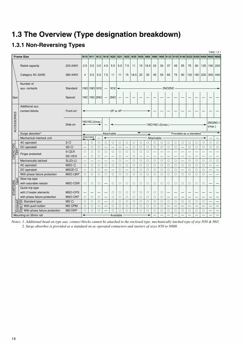
Mounting on 35mm rail
Notes: 1. Additional head-on type aux. contact blocks cannot be attached to the enclosed type, mechanically latched type of size N50 & N65.2. Surge absorber is provided as a standard on ac operated contactors and starters of sizes N50 to N800.
N300
90
160
—
—
�
�
—
—
�
�
�
�
�
—
—
�
—
�
—
1.3 The Overview (Type designation breakdown)
N10
2.5
4
1NO
1NC
�
—
�
—
—
�
—
�
�
—
�
�
�
�
N180
55
90
—
—
�
—
—
—
—
�
—
�
�
—
—
�
—
�
—
Provided as a standard
N125
37
60
—
—
�
�
—
—
�
�
�
�
�
—
—
�
—
�
—
N800
220
440
—
—
—
�
�
—
—
�
—
—
—
—
—
—
—
—
—
—
N600
190
330
—
—
—
�
�
—
—
�
—
—
—
—
—
—
—
—
—
—
N80
22
45
—
—
�
�
—
—
�
�
�
�
�
�
�
�
�
�
—
N150
45
75
—
—
�
�
—
—
�
�
�
�
�
—
—
�
—
�
—
2NO2NC
Attachable
Attachable
Available
N95
30
55
—
—
�
�
—
—
�
�
�
�
�
�
�
�
�
�
—
N220
75
132
—
—
�
�
—
—
�
�
�
�
�
—
—
�
—
�
—
N400
125
220
—
—
�
�
—
—
�
�
�
�
�
—
—
�
—
�
—
Frame Size
Rated capacity
Category AC-3(kW)
Number of
aux. contacts
Additional aux.
contact blocks
Surge absorber3
Mechanical interlock unit
AC operated
DC operated
Finger protected
Mechanically latched
AC operated
DC operated
With phase failure protection
Slow trip type
with saturable reactor
Quick-trip type
with 2 heater elements
with phase failure protection
Standard type
With push button
With phase failure protection
Spec
AC
CE
SS
OR
IES
Ope
nCO
NTAC
TORS
220-240V
380-440V
Standard
Special
Front-on1
Side-on
S-
SD-
S- CX
SD- CX
SL(D)-
MSO-
MSOD-
MSO- KP
MSO- SR
MSO- FS
MSO- KF
MS-
MS- PM
MS- KP
ST
AR
TE
RS
Ope
nE
nclo
sed
Cla
ss IP
20
1NO1NC×2(max.)
1.3.1 Non-Reversing Types
1NO1NC×2(max.) 2NO2NC×1(max.)
N25
7.5
15
—
�
—
�
—
—
�
—
�
�
�
�
�
�
�
Attachable
N35
11
18.5
—
�
�
�
�
�
�
�
�
�
�
�
�
�
�
2P or 4P
Table 1.3.1

15
Notes: 1. Additional head-on type aux. contact blocks cannot be attached to the enclosed type, mechanically latched type of size N50 & N65.2. Surge absorber is provided as a standard on ac operated contactors and starters of sizes 2xN50 to 2xN800.3. Remove a mounting plate for mounting on 35mm rail of sizes 2xN25 to 2xN65.
Mounting on 35mm rail
ST
AR
TE
RS
2x
N20
5.5
11
1NO1NC
×2
—
�
—
�
—
�
—
�
�
�
�
�
�
2x
N21
5.5
11
—
�
�
�
�
�
�
�
�
�
�
�
�
2x
N25
7.5
15
—
�
—
�
—
�
—
�
�
�
�
�
�
2x
N11
3.5
5.5
—
�
�
�
—
�
�
�
�
—
�
—
�
1.3.2 Reversing Type
2x
N180
55
90
—
—
�
—
—
—
�
—
�
�
—
—
�
�
—
Provided as a standard
2x
N400
125
220
—
—
�
�
—
�
�
�
�
�
—
—
�
—
—
2x
N18
4.5
7.5
2NO2NC
×2
—
—
—
�
—
�
—
�
—
�
—
—
—
�
—
Attachable
Available3
2x
N10
2.5
4
—
�
—
�
—
�
—
�
�
—
�
—
�
220-240V
380-440V
Standard
Special
Front-on1
Side-on
S-
SD-
S- CX
SL(D)-
MSO-
MSOD-
MSO- KP
MSO- SR
MSO- FS
MSO- KF
MS-
MS- KP
2x
N125
37
60
—
—
�
�
—
�
�
�
�
�
—
—
�
�
—
2x
N95
30
55
—
—
�
�
—
�
�
�
�
�
—
—
�
�
—
2x
N600
190
330
—
—
—
�
�
—
�
—
—
—
—
—
—
—
—
—
2x
N150
45
75
—
—
�
�
—
�
�
�
�
�
—
—
�
�
—
2x
N220
75
132
—
—
�
�
—
�
�
�
�
�
—
—
�
�
—
2x
N300
90
160
—
—
�
�
—
�
�
�
�
�
—
—
�
—
—
2x
N800
220
440
—
—
—
�
�
—
�
—
—
—
—
—
—
—
—
—
2x
N80
22
45
—
—
�
�
—
�
�
�
�
�
�
�
�
�
—
2x
N65
18.5
30
—
�
�
�
�
�
�
�
�
�
�
�
�
2x
N50
15
22
—
�
�
�
�
�
�
�
�
�
�
�
�
2x
N35
11
18.5
—
�
�
�
�
�
�
�
�
�
�
�
�
Rated capacity
Category AC-3(kW)
Number of
aux. contacts
Additional aux.
contact blocks
Surge absorber2
AC operated
DC operated
Finger protected
Mechanically latched
AC operated
DC operated
With phase failure protection
Slow trip type
with saturable reactor
Quick-trip type
with 2 heater elements
with phase failure protection
Standard type
With phase failure protection
2NO2NC×2
Spec
AC
CE
SS
-O
RIE
SO
pen
CONT
ACTO
RSE
nclo
sed(
IP20
)
1NO1NC×2
3NO3NC×2
Frame Size
4NO4NC
×21NO1NC×2
1NO1NC×2
4P×2 2P×2
4P×2 2P×2
Ope
n
Table 1.3.2

16
69032
12(32)20(32)25(32)30(32)
2222179
2.23.73.73.713
202020
20158
5.5101010
220/220220/220
1,8001,800600
15103312
9015499
10
1-61-6
1-2.5—
69020
7.5(20)7(11)7(8)7(6)
11975
0.751.11.11.16
1088
642
2.23.34
3.3
110/110100/721,8001,800600
1510——
457
2.4——
10
1-2.51-2.51-2.5
—
690100
35(100)65(100)85(100)
100(100)
65656038
7.511111147
656550
403515
20403540
650/620650/620
1,2001,200600
25535715
115202.21818
5
2-252-251-2.5
—
Rated insulation voltageConventional free air thermal currentRated capacity for resistive loads3-ph, Category AC-1
Rated operational current3-ph, Category AC-3
Rated capacity for jogging of AC motors3-ph, category AC-4Electrical life is ca.200,000 operations
Max. current for AC-4 duty at 440VRated current for DC non-inductive loadsCategory DC-1100 operations/hour max.500,000 operations
Rated Current for DC motorsCategory DC-2 & DC-4100 operations/hour max.500,000operations
Applicable standard: JEM-1038 (JAPAN)Rated capacity for 3-ph, capacitors4
120 operations/hour max.Electrical durability at maximum load:100,000 operations(ambient temperature 40°C)Making & breaking3-ph, cosΘ=0.35240V/440VSwitching frequency
Operating time (at rated coil voltage)AC operated
DC operated
Coil consumption (at rated coil voltage)AC operated
DC operated
Coil voltage toleranceMechanical endurance (make/break operations)Permissible ambient temperatureVibration (10-55 Hertz)Shock (10 ms half sine wave)
Main terminal (contactor)Main terminal (overload relay)
Control terminalBusbar width
1.4 Technical Data of Series S-N Contactors1.4.1 Ratings and Characteristics
TypeContactor
Notes: 1. 660A at ambient temperature 40-55°C. 2. 800A at ambient temperature 40-55°C.3. Conductor size in parentheses indicate compression terminal style not for bare clamping.4. The peak value of inrush current should be less than 2000% of the effective value for rated current of capacitors.
The selection is invalid for the circuit of parallel capacitors which are controlled individually.
VA
kW(A)kW(A)kW(A)kW(A)
AAAA
kWkWkWkWA
AAA
AAA
kvarkvarkvarkvar
AAoperations/houroperations/houroperations/hour
msmsmsms
VAVAWVAVA
million°Cm/s2
m/s2
mm2
mm2
mm2
mm
S-N1069020
7.5(20)8.5(13)9.5(11)
8(8)
131297
1.11.51.51.59
121212
1084
345
4.5
130/120120/100
1,8001,800600
15104510
457
2.477
10
1-2.51-2.51-2.5
—
S/SD-N11, N12
69025
9.5(25)13(20)13(16)11(10)
1816139
1.52.22.22.29
121212
1084
466
5.5
180/180180/130
1,8001,800600
1510——
60103——
10
1-61-6
1-2.5—
S-N18
0.85 to 1.1 times rated coil voltage
69032
12(32)20(32)25(32)30(32)
2222179
2.23.73.73.713
202020
20158
5.5101010
220/220220/220
1,8001,800600
1510——
90154——
10
1-61-6
1-2.5—
S-N20
–25 to +5519.649
S/SD-N21
69050
18(50)30(50)40(50)50(50)
30302412
35.55.55.517
252522
252010
8.5141414
300/300300/240
1,8001,800600
1510——
110134.3——
10
2-162-161-2.5
—
S-N2569060
20(60)35(60)50(60)60(60)
40403217
3.75.55.55.524
353530
302010
12202020
400/400400/320
1,8001,800600
15105013
110134.399
10
2-162-161-2.5
—
S/SD-N35
69080
30(80)50(80)65(80)80(80)
55503826
5.57.57.57.532
505040
353012
20403030
550/460550/460
1,2001,200600
25535715
115202.21818
5
2-252-251-2.5
—
S/SD-N50
S/SD-N65
Ith
220-240V380-440V
500V690V
220-240V380-440V
500V690V
220-240V380-440V
500V690V
48V110V220V
48V110V220V
220-240V380-440V
550V690V
Making currentBreaking currentCategory AC-1Category AC-3Category AC-4
ClosingOpeningClosingOpening
InrushSealedWattsInrushSealed
Conductor size

17
690260
95(260)170(260)220(260)260(260)
180180180120
22374550150
180180180
180150100
60120150150
1800/18001450/1450
1,2001,200300
30100——
440404.2——
5
(10-120)3
(10-120)3
1-2.525
690260
95(260)170(260)220(260)260(260)
250250200150
22455555180
220220220
220150100
60120150150
2500/25002000/2000
1,2001,200300
3010014540
440404.24141
5
(10-150)3
(10-150)3
1-2.525
A
A
A
A
A
A
A
A
A
A
Conventional free airthermal current
Rated operating current
Category 120VAC
AC-15 240VAC
500VAC
660VAC
Category 24VDC
48VDC
DC-13 110VDC
220VDC
69010002
300(800)530(800)700(800)900(800)
800800720630
75130150150630
800800800
630630630
190350350400
8000/80006400/6400
1,2001,200300
657510580
790901760072
5
(70-325)3
—1-435
S/SD-N600
S/SD-N400
6908001
250(660)430(660)570(660)660(660)
630630500420
65110130130400
630630630
630630630
190350350400
6500/65005040/5040
1,2001,200300
657510580
790901760072
5
(70-325)3
—1-435
690135
50(135)85(135)
110(135)135(135)
85857552
7.515151562
808060
605020
35604850
850/850800/750
1,2001,200600
27757518
210232.82424
5
2-602-501-2.5
15
S/SD-N80
690150
55(150)90(150)
120(150)150(150)
1051058565
1118.518.518.575
939370
908050
35606060
1050/1050930/9301,2001,200300
27757518
210 232.82424
5
(2-60)3
2-501-2.5
15
S/SD-N95
690150
55(150)90(150)
120(150)150(150)
1251209070
1522222290
12010080
908050
38656565
1250/12501000/1000
1,2001,200300
258512522
270242.93131
5
(6-70)3
(6-70)3
1-2.515
S/SD-N125
0.85 to 1.1 times rated coil voltage
690200
75(200)130(200)170(200)200(200)
150150140100
18.5303730110
150150150
13012080
50808080
1500/15001200/1200
1,2001,200300
278513537
270242.93131
5
(6-95)3
(6-95)3
1-2.520
S/SD-N150
–25 to +5519.649
S-N180
S/SD-N220
690350
130(350)230(350)300(350)350(350)
300300250220
37606075220
300300300
280200150
95150200200
3000/30002400/2400
1,2001,200300
3512017555
440506.15555
5
(25-240)3
(25-240)3
1-2.530
S/SD-N300
690450
170(450)290(450)380(450)450(450)
400400350300
45759090300
400400300
280200150
115200250200
4000/40003200/3200
1,2001,200300
3512017555
440506.15555
5
(25-240)3
(25-240)3
1-2.530
S/SD-N800
Table 1.4.1 (1)
Rated operating current ofauxiliary contacts
Table 1.4.1 (2)
16
6
5
3
1.5
5
3
0.6
0.81
0.2
Note: 1 UN-AX2(CX), UN-AX4(CX),UN-AX11(CX).

18
1.4.2 Performance of Series S-N Contactors
·
Electrical LifeThe electrical life of the main contacts of a contactor isdetermined mainly by the circuit-opening duty it will perform.The relationship between electrical life and rated current ofMitsubishi contactors under normal and jogging duties ofsquirrel-cage motors is shown in Fig. 1.4.2(1) and 1.4.2(2).In the case of a mixture of normal and jogging duties, theexpected contactor life can be determined as follows:
N = Nr/1 + (Nr/NI -1) ...................................... Eq.1.1
where N : Life in the case of α% jogging dutyNr : Life in the case of normal dutyNl : Life in the case of 100% jogging dutyα : Percentage of jogging duty
Electrical life versus rated operating current
Normal duty, 6le on, le off, on-load factor 40%,1200 operations/hour (AC3)Jogging duty, 6le on, 6le off, on-load factor 7%,600 operations/hour (AC4)-S-N10~S-N300300 operations/hour (AC4)-S-N400~S-N600150 operations/hour (AC4)-S-N800
1.4.3 Mounting Attitude of Starters and Contactors
To assure proper performance, Mitsubishi magnetic motorstarters and contactors should be mounted on a verticalsupporting surface with the line terminals upwards and theload terminals downwards. The supporting surface may havea maximum inclination of 30° from the vertical in any direction.
α100
30° 30° 30° 30°
Inclined installationRegular installation
Bottom
Top
220~240VAC Fig.1.4.2 (1)5
3
2
1.5
1
0.7
0.5
0.3
0.2
0.15
0.1
0.07
0.05
0.03
0.02
0.012 3 5 7 10 15 20 30 50
Rated operating current (A)
Ele
ctric
al li
fe (
mill
ion
of o
pera
tions
, ave
rage
)
70 100 150 200 300 500 800
S-N800S-N600
S-N400S-N300
S-N150S-N50 S-N80
S-N95
S-N125S-N25
S-N20,21
S-N11,12
S-N10
S-N18
S-N35
S-N65
S-N180
S-N220
380~440VAC Fig.1.4.2 (2)5
3
2
1.5
1
0.7
0.5
0.3
0.2
0.15
0.1
0.07
0.05
0.03
0.02
0.012 3 5 7 10 15 20 30 50
Rated operating current (A)
Ele
ctric
al li
fe (
mill
ion
of o
pera
tions
, ave
rage
)
70 100 150 200 300 500 800
S-N800S-N600
S-N400
S-N300
S-N220S-N150
S-N80
S-N95
S-N180S-N125
S-N20,21S-N11,N12S-N18S-N10
S-N25S-N50
S-N35S-N65

19
AC24V
AC48V
AC100V
AC120V
AC127V
AC200V
AC220V
AC230V
AC260V
AC380V
AC400V
AC440V
AC500V
1.5 When OrderingContactors, indicate the model name and the ordering designation of the coil.
Example: S-N20 ∗AC230V (∗ 2A) Code of arrangement, if special aux. contacts, ref. Table 1.5.4
Ordering designation of the coilModel name
Overload relays, indicate the model name and the ordering designation of the heater setting range.
Example: TH-N400RHKP∗250AOrdering designation of the heater setting rangeModel name
Motor starters, indicate the model name, heater setting range, main circuit voltage, coil designation.
Example: MSO-N11KP∗6.6A∗380V∗AC230VOrdering designation of the coil
Main circuit voltageOrdering designation of the heater setting range
Model name
Note: Mark ∗ indicates a blank space.
Coil Ratings and Ordering Designationsfor S-N10(CX), -N11(CX), -N12(CX), -N18(CX), -N20(CX),
-N21(CX), -N25(CX), -N35(CX) and SR-N(CX)Table 1.5.1
50Hz
24
48~50
100
110~120
125~127
200
208~220
220~240
240~260
346~380
380~415
415~440
500
60Hz
24
48~50
100~110
115~120
127
200~220
220
230~240
260~280
380
400~440
460~480
500~550
Rated voltage (VAC)Ordering designation
Ordering designation
DC24V
DC48V
DC100V
DC110V
DC125V
DC200V
DC220V
Rated voltage (VDC)
24
48
100
110
120~125
200
220
Table 1.5.3
for SD-N, SRD-N
Ordering designation
AC100V
AC200V
AC300V
AC400V
AC500V
Rated voltage (50/60Hz)
100~127V
200~240V
260~350V
380~440V
460~550V
Table 1.5.2
for S-N50(CX)~-N800
AC24V,AC48V are available for S-N50(CX)~-N150
Code
1B
2A
Arrangement
1NC
2NO
Table 1.5.4
Code of arrangement for sepcial aux. Contacts
A : Normally Open
B : Normally Closed

20
—
1
—
1
1
—
—
1
—
2
2
2
2
2
2
2
2
2
2
2
2
2
2
2
—
—
—
—
SD-N50
SD-N65
SD-N80
SD-N95
SD-N125
SD-N150
—
SD-N220
SD-N300
SD-N400
SD-N600
SD-N800
S-N80
S-N95
S-N125
S-N150
S-N180
S-N220
S-N300
S-N400
S-N600
S-N800
1
—
1
—
1
2
—
1
2
2
2
2
2
2
2
2
2
2
2
2
2
2
2
2
7.5
7.5
7.5
11
15
22
30
45
55
60
90
110
132
200
250
330
500
16
22
22
30
40
50
65
85
105
120
150
180
250
300
400
630
800
18
22
22
30
40
55
65
85
105
125
150
180
250
300
400
630
800
4.5
5.5
5.5
7.5
11
15
18.5
22
30
37
45
55
75
90
125
190
220
SD-N11SD-N11CX1
SD-N11(1B)SD-N11CX1(1B)SD-N12SD-N12CX1
SD-N12(2A)SD-N12CX1(2A)
1.6.1 Non-Reversing Contactors
Ordering Designation
Model name ................................................................................................. S-N10Coil designation (See page 13) ............................................................................... AC400VIf required special aux. contact (never specify for standard). ................................................. 1B
Complete type designation S-N10∗AC400V∗1B
Note: Mark∗indicatesa blank space.
Rated
operational
current AC-3
220
–240V
(A)
380
–440V
(A)
500V
(kW)
690V
(kW)
Rated motor capacity
3-phase AC-2 & AC-3
Model name
AC operated
220
–240V
(kW)
380
–440V
(kW)
DC operated
—
Standard
aux.
contacts
Finger
protection
terminal cover
Additional auxiliary contact block
NO NC
UN-
AX2(CX)
UN-
AX4(CX)–
Provided–
Provided–
Provided–
Provided–
Provided–
Provided–
Provided–
Provided–
Provided–
Provided–
Provided–
Provided–
Provided–
Provided
S-N10S-N10CX1
S-N10(1B)S-N10CX1(1B)S-N11S-N11CX1
S-N11(1B)S-N11CX1(1B)S-N12S-N12CX1
S-N12(2A)S-N12CX1(2A)S-N18S-N18CX1
S-N20S-N20CX1
S-N20(2A)S-N20CX1(2A)S-N21S-N21CX1
S-N25S-N25CX1
S-N35S-N35CX1
S-N50S-N50CX1
S-N65S-N65CX1
7.5
11
11
15
18.5
22
30
45
55
60
75
90
132
160
220
330
440
7.5
11
11
15
18.5
25
37
45
55
60
90
110
132
160
225
330
500
SD-N21SD-N21CX1
SD-N35SD-N35CX1
—
—
—
—
—
—
—
—
—
—
—
—
UN-
AX80
UN-
AX150
UN-
AX600
— —Max.
2
——Max.
2
— — 1
1.6 Selection Table of Contactors
Table 1.6.1
Type S-N , SD-N
2 — — —
1
—11 4 4 42.59
13
13
3.5
3.5
12
12
5.5
5.5
5.5
5.5
5.5
5.5
— — —
— — —
S-N10CX S-N21 SD-N65 S-N220 SD-N400 S-N800
—
2
UN-
AX11(CX)
Note:1 “CX” denotes with finger protection terminal covers.
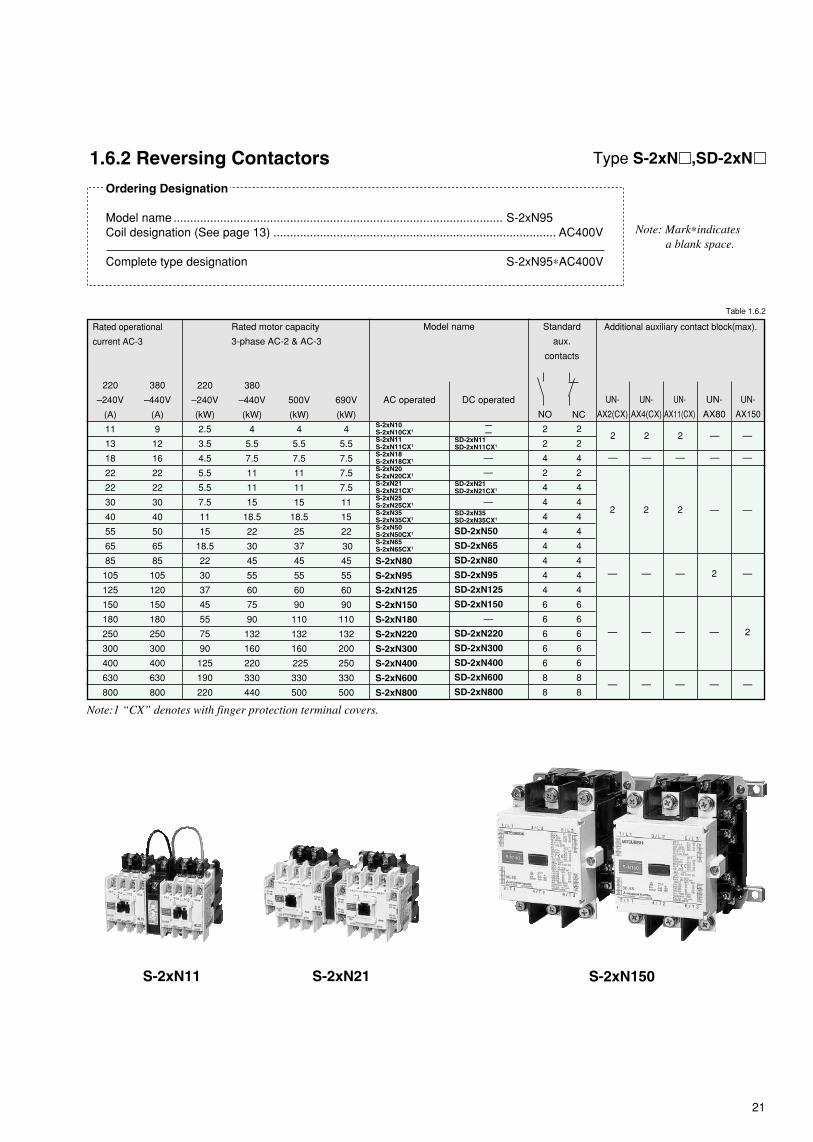
21
—
—
—
SD-2xN50
SD-2xN65
SD-2xN80
SD-2xN95
SD-2xN125
SD-2xN150
—
SD-2xN220
SD-2xN300
SD-2xN400
SD-2xN600
SD-2xN800
S-2xN150S-2xN21
2
2
4
2
4
4
4
4
4
4
4
4
6
6
6
6
6
8
8
DC operated
380
–440V
(kW)
1.6.2 Reversing Contactors
Ordering Designation
Model name ................................................................................................... S-2xN95Coil designation (See page 13) ..................................................................................... AC400V
Complete type designation S-2xN95∗AC400V
Note: Mark∗indicatesa blank space.
Rated operational
current AC-3
220
–240V
(A)
380
–440V
(A)
11
13
18
22
22
30
40
55
65
85
105
125
150
180
250
300
400
630
800
9
12
16
22
22
30
40
50
65
85
105
120
150
180
250
300
400
630
800
S-2xN11
Type S-2xN ,SD-2xN
500V
(kW)
690V
(kW)
Rated motor capacity
3-phase AC-2 & AC-3
220
–240V
(kW)
4
5.5
7.5
11
11
15
18.5
22
30
45
55
60
75
90
132
160
220
330
440
4
5.5
7.5
11
11
15
18.5
25
37
45
55
60
90
110
132
160
225
330
500
4
5.5
7.5
7.5
7.5
11
15
22
30
45
55
60
90
110
132
200
250
330
500
2.5
3.5
4.5
5.5
5.5
7.5
11
15
18.5
22
30
37
45
55
75
90
125
190
220
Model name
AC operated
Standard
aux.
contacts
NO
2
2
4
2
4
4
4
4
4
4
4
4
6
6
6
6
6
8
8
Additional auxiliary contact block(max).
S-2xN80
S-2xN95
S-2xN125
S-2xN150
S-2xN180
S-2xN220
S-2xN300
S-2xN400
S-2xN600
S-2xN800
S-2xN10S-2xN10CX1
S-2xN11S-2xN11CX1
S-2xN18S-2xN18CX1
S-2xN20S-2xN20CX1
S-2xN21S-2xN21CX1
S-2xN25S-2xN25CX1
S-2xN35S-2xN35CX1
S-2xN50S-2xN50CX1
S-2xN65S-2xN65CX1
NC
UN-
AX2(CX)
UN-
AX4(CX)
UN-
AX11(CX)
UN-
AX80
UN-
AX150
— — — — —
Table 1.6.2
2
—
—
2
—
—
2
—
—
—
2
—
—
—
2
2
—
2
—
2
—
—
—
—
—
——
SD-2xN11SD-2xN11CX1
SD-2xN21SD-2xN21CX1
SD-2xN35SD-2xN35CX1
Note:1 “CX” denotes with finger protection terminal covers.

22
—
—
—
Max.2
Max.2
—
—
— —
2
2
2
2
2
2
2
2
2
2
2
2
2
1.6.3 Non-Reversing Mechanically Latched Contactors
Ordering DesignationModel name ......................................................................... SL-N35Closing coil designation1 ......................................................................... AC200VTripping coil designation1 .............................................................................................. DC100V
Complete type designation SL-N35∗MC·AC200V∗MT·DC100V
Type SL-N , SLD-N
Note: Mark∗indicatesa blank space.1. See Table1.6.3 (2).
DC operated
(closing coil)
380
–440V
(kW)
Rated operational
current AC-3
220
–240V
(A)
380
–440V
(A)
22
40
55
65
85
105
125
150
250
300
400
630
800
22
40
50
65
85
105
120
150
250
300
400
630
800
500V
(kW)
690V
(kW)
Rated motor capacity
3-phase AC-2 & AC-3
220
–240V
(kW)
11
18.5
22
30
45
55
60
75
132
160
220
330
440
11
18.5
25
37
45
55
60
90
132
160
225
330
500
7.5
15
22
30
45
55
60
90
132
200
250
330
500
5.5
11
15
18.5
22
30
37
45
75
90
125
190
220
Model name
AC operated
(closing coil)
Standard
free aux.
contacts
Additional auxiliary contact block
UN-
AX11
UN-
AX150
UN-
AX600
UN-
AX80
SL-N21
SL-N35
SL-N50
SL-N65
SL-N80
SL-N95
SL-N125
SL-N150
SL-N220
SL-N300
SL-N400
SL-N600
SL-N800
SLD-N21
SLD-N35
SLD-N50
SLD-N65
SLD-N80
SLD-N95
SLD-N125
SLD-N150
SLD-N220
SLD-N300
SLD-N400
SLD-N600
SLD-N800
2
2
2
2
1
1
1
1
1
1
1
1
1
Table 1.6.3 (1)
—
Max.2
—
—
—
1
• Coil Ratings (Closing & Tripping)Table 1.6.3 (2)
Orderingdesignation
DC24VDC48V
DC100VDC125VDC200V
100-127VAC 50/60Hz200-240VAC 50/60Hz260-350VAC 50/60Hz380-440VAC 50/60Hz460-550VAC 50/60Hz
24VDC48VDC
100-110VDC120-125VDC200-220VDC
Applicable voltage
• Precautions• Minimum energising time, both for closing and tripping must
be set longer than the followings.SL(D)-N21 to N220 : 0.3 sec.SL(D)-N300 to N800 : 0.5 sec.
• Make sure never to over lap the energising time for closingand tripping.
SL-N35
AC100VAC200VAC300VAC400VAC500V
—
SL-N150

23
—
—
—
SLxS-N65
—
—
SLxS-N125
SLxS-N150
SLxS-N220
SLxS-N300
SLxS-N400
—
—
Max.2
—
1.6.4 Reversing Mechanically Latched Contactors (Components for Automatic Transfer Switches) Type SL-2xN , SLD-2xN , SLxS-N
Ordering Designation
• Mechanically latched & mechanically latched contactorModel name ......................................................... SL-2xN35Closing coil designation in normal left side1 ................................... AC200VTripping coil designation in normal left side1 ......................................................... DC100VClosing coil designation in standby right side1 .............................................................................. DC100VTripping coil designation in standby right side1 ..................................................................................................... AC200V
Complete type designation SL-2xN35∗MC1-AC200V∗MT1-DC100V∗MC2-DC100V∗MT2-AC200V
• Mechanically latched & normal contactorModel name ....................................................................................... SLxS-N150Closing coil designation in normal left side1 ................................................................... AC200VTripping coil designation in normal left side1 .......................................................................................... AC100VCoil designation in standby right side2 .................................................................................................................. AC100V
Complete type designation SLxS-N150∗MC1-AC200V∗MT1-AC100V∗AC100V
Notes: Mark∗indicates a blank space. 1. See Table 1.6.3(2) 2. See Table 1.5.2
DC operated
(closing coil)
380
–440V
(kW)
Rated operational
current AC-3
220
–240V
(A)
380
–440V
(A)
22
40
55
65
85
105
125
150
250
300
400
630
800
22
40
50
65
85
105
120
150
250
300
400
630
800
500V
(kW)
690V
(kW)
Rated motor capacity
3-phase AC-2 & AC-3
220
–240V
(kW)
11
18.5
22
30
45
55
60
75
132
160
220
330
440
11
18.5
25
37
45
55
60
90
132
160
225
330
500
7.5
15
22
30
45
55
60
90
132
200
250
330
500
5.5
11
15
18.5
22
30
37
45
75
90
125
190
220
Model name
mechanically latched
& mechaniclly latched
AC operated
(closing coil)
Additional auxiliary contact block
SL-2xN21
SL-2xN35
SL-2xN50
SL-2xN65
SL-2xN80
SL-2xN95
SL-2xN125
SL-2xN150
SL-2xN220
SL-2xN300
SL-2xN400
SL-2xN600
SL-2xN800
SLD-2xN21
SLD-2xN35
SLD-2xN50
SLD-2xN65
SLD-2xN80
SLD-2xN95
SLD-2xN125
SLD-2xN150
SLD-2xN220
SLD-2xN300
SLD-2xN400
SLD-2xN600
SLD-2xN800
Table 1.6.4
UN-AX11
—
—
UA-AX80
—
—
UA-AX150
AC operated
(closing coil)
Mechanically
latched & normal
• Precautions• Minimum energising time both for closing and tripping must be set
longer than the followings.SL(D)-2xN21 to N220, SLxS-N65 to N220 : 0.3 sec.SL(D)-2xN300 to N800, SLxS-N300 and N400 : 0.5 sec.
Make sure never to overlap the energising time for closing and tripping.
SL-2xN35
—— Max.2
Max.2 — —
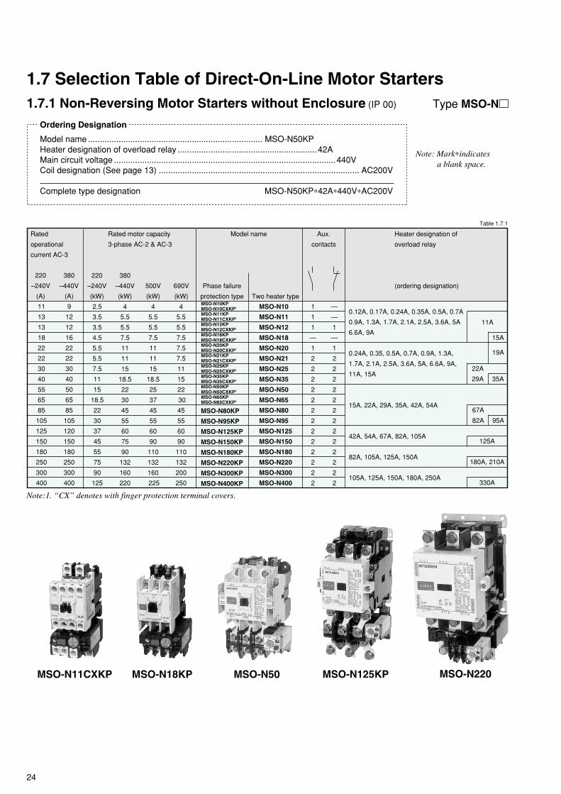
24
1.7.1 Non-Reversing Motor Starters without Enclosure (IP 00)
Ordering Designation
Model name .......................................................................... MSO-N50KPHeater designation of overload relay ...........................................................42AMain circuit voltage ..............................................................................................440VCoil designation (See page 13) ..................................................................................... AC200V
Complete type designation MSO-N50KP∗42A∗440V∗AC200V
Note: Mark∗indicatesa blank space.
Type MSO-N
1.7 Selection Table of Direct-On-Line Motor Starters
MSO-N10
MSO-N11
MSO-N12
MSO-N18
MSO-N20
MSO-N21
MSO-N25
MSO-N35
MSO-N50
MSO-N65
MSO-N80
MSO-N95
MSO-N125
MSO-N150
MSO-N180
MSO-N220
MSO-N300
MSO-N400
—
—
1
—
1
2
2
2
2
2
2
2
2
2
2
2
2
2
1
1
1
—
1
2
2
2
2
2
2
2
2
2
2
2
2
2
Rated
operational
current AC-3
220
–240V
(A)
Heater designation of
overload relay
(ordering designation)
11
13
13
18
22
22
30
40
55
65
85
105
125
150
180
250
300
400
Table 1.7.1
500V
(kW)
Rated motor capacity
3-phase AC-2 & AC-3
220
–240V
(kW)
380
–440V
(kW)
4
5.5
5.5
7.5
11
11
15
18.5
22
30
45
55
60
75
90
132
160
220
4
5.5
5.5
7.5
11
11
15
18.5
25
37
45
55
60
90
110
132
160
225
2.5
3.5
3.5
4.5
5.5
5.5
7.5
11
15
18.5
22
30
37
45
55
75
90
125
Model name
Phase failure
protection type Two heater type
690V
(kW)
4
5.5
5.5
7.5
7.5
7.5
11
15
22
30
45
55
60
90
110
132
200
250
380
–440V
(A)
9
12
12
16
22
22
30
40
50
65
85
105
120
150
180
250
300
400
MSO-N80KP
MSO-N95KP
MSO-N125KP
MSO-N150KP
MSO-N180KP
MSO-N220KP
MSO-N300KP
MSO-N400KP
Aux.
contacts
11A
35A
22A
29A
0.24A, 0.35, 0.5A, 0.7A, 0.9A, 1.3A,
1.7A, 2.1A, 2.5A, 3.6A, 5A, 6.6A, 9A,
11A, 15A
125A
67A
42A, 54A, 67A, 82A, 105A
180A, 210A82A, 105A, 125A, 150A
330A105A, 125A, 150A, 180A, 250A
Note:1. “CX” denotes with finger protection terminal covers.
15A, 22A, 29A, 35A, 42A, 54A
0.12A, 0.17A, 0.24A, 0.35A, 0.5A, 0.7A
0.9A, 1.3A, 1.7A, 2.1A, 2.5A, 3.6A, 5A
6.6A, 9A
19A
15A
MSO-N11CXKP MSO-N50MSO-N18KP MSO-N125KP MSO-N220
MSO-N10KPMSO-N10CXKP1
MSO-N11KPMSO-N11CXKP1
MSO-N12KPMSO-N12CXKP1
MSO-N18KPMSO-N18CXKP1
MSO-N20KPMSO-N20CXKP1
MSO-N21KPMSO-N21CXKP1
MSO-N25KPMSO-N25CXKP1
MSO-N35KPMSO-N35CXKP1
MSO-N50KPMSO-N50CXKP1
MSO-N65KPMSO-N65CXKP1
95A82A

25
1.7.2 Reversing Motor Starters without Enclosure (IP 00)
Ordering Designation
Model name ...................................................................... MSO-2xN35KPHeater designation of overload relay ...........................................................29AMain circuit voltage .............................................................................................. 440VCoil designation (See page 13) ..................................................................................... AC200V
Complete type designation MSO-2xN35KP∗29A∗440V∗AC200V
Note: Mark∗indicatesa blank space.
Type MSO-2xN
—
—
2
—
2
2
2
2
2
2
2
2
4
4
4
4
4
2
2
4
2
4
4
4
4
4
4
4
4
6
6
6
6
6
Rated
operational
current AC-3
220
–240V
(A)
Heater designation of
overload relay
(ordering designation)
11
13
18
22
22
30
40
55
65
85
105
125
150
180
250
300
400
500V
(kW)
Rated motor capacity
3-phase AC-2 & AC-3
220
–240V
(kW)
380
–440V
(kW)
4
5.5
7.5
11
11
15
18.5
22
30
45
55
60
75
90
132
160
220
4
5.5
7.5
11
11
15
18.5
25
37
45
55
60
90
110
132
160
225
2.5
3.5
4.5
5.5
5.5
7.5
11
15
18.5
22
30
37
45
55
75
90
125
Model name
Phase failure
protection typeMSO-2xN10KPMSO-2xN10CXKP1
MSO-2xN11KPMSO-2xN11CXKP1
MSO-2xN18KPMSO-2xN18CXKP1
MSO-2xN20KPMSO-2xN20CXKP1
MSO-2xN21KPMSO-2xN21CXKP1
MSO-2xN25KPMSO-2xN25CXKP1
MSO-2xN35KPMSO-2xN35CXKP1
MSO-2xN50KPMSO-2xN50CXKP1
MSO-2xN65KPMSO-2xN65CXKP1
Two heater type
690V
(kW)
4
5.5
7.5
7.5
7.5
11
15
22
30
45
55
60
90
110
132
200
250
380
–440V
(A)
9
12
16
22
22
30
40
50
65
85
105
120
150
180
250
300
400
Free aux.
contacts
19A
180A, 210A82A, 105A, 125A, 150A
330A105A, 125A, 150A, 180A, 250A
MSO-2xN80KP
MSO-2xN95KP
MSO-2xN125KP
MSO-2xN150KP
MSO-2xN180KP
MSO-2xN220KP
MSO-2xN300KP
MSO-2xN400KP
MSO-2xN10
MSO-2xN11
MSO-2xN18
MSO-2xN20
MSO-2xN21
MSO-2xN25
MSO-2xN35
MSO-2xN50
MSO-2xN65
MSO-2xN80
MSO-2xN95
MSO-2xN125
MSO-2xN150
MSO-2xN180
MSO-2xN220
MSO-2xN300
MSO-2xN400
Note:1. “CX” denotes with finger protection terminal covers.
125A
67A
0.12A, 0.17A, 0.24A, 0.35A, 0.5A, 0.7A
0.9A, 1.3A, 1.7A, 2.1A, 2.5A, 3.6A, 5A
6.6A, 9A, 11A
22A
35A29A
0.24A, 0.35A, 0.5A, 0.7A, 0.9A, 1.3A,
1.7A, 2.1A, 2.5A, 3.6A, 5A, 6.6A,
9A, 11A, 15A
15A, 22A, 29A, 35A, 42A, 54A
42A, 54A, 67A, 82A, 105A
15A
MSO-2xN35MSO-2xN11KP MSO-2xN18 MSO-2xN150KP
Table 1.7.2
95A82A
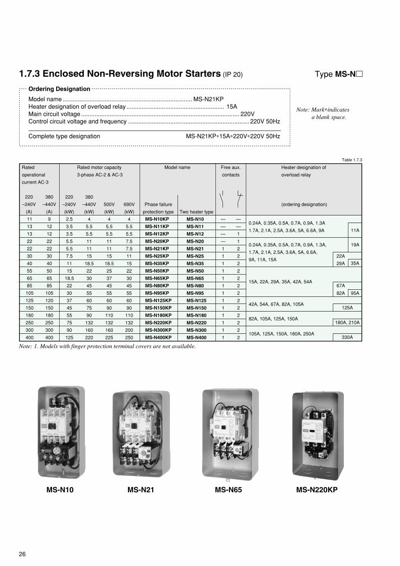
26
1.7.3 Enclosed Non-Reversing Motor Starters (IP 20)
Ordering Designation
Model name ............................................................................. MS-N21KPHeater designation of overload relay .......................................................... 15AMain circuit voltage .............................................................................................. 220VControl circuit voltage and frequency ........................................................................ 220V 50Hz
Complete type designation MS-N21KP∗15A∗220V∗220V 50Hz
Note: Mark∗indicatesa blank space.
Type MS-N
105A, 125A, 150A, 180A, 250A
MS-N10
MS-N11
MS-N12
MS-N20
MS-N21
MS-N25
MS-N35
MS-N50
MS-N65
MS-N80
MS-N95
MS-N125
MS-N150
MS-N180
MS-N220
MS-N300
MS-N400
—
—
1
1
2
2
2
2
2
2
2
2
2
2
2
2
2
—
—
—
—
1
1
1
1
1
1
1
1
1
1
1
1
1
Rated
operational
current AC-3
220
–240V
(A)
Heater designation of
overload relay
(ordering designation)
11
13
13
22
22
30
40
55
65
85
105
125
150
180
250
300
400
Table 1.7.3
500V
(kW)
Rated motor capacity
3-phase AC-2 & AC-3
220
–240V
(kW)
380
–440V
(kW)
4
5.5
5.5
11
11
15
18.5
22
30
45
55
60
75
90
132
160
220
4
5.5
5.5
11
11
15
18.5
25
37
45
55
60
90
110
132
160
225
2.5
3.5
3.5
5.5
5.5
7.5
11
15
18.5
22
30
37
45
55
75
90
125
Model name
Phase failure
protection type Two heater type
690V
(kW)
4
5.5
5.5
7.5
7.5
11
15
22
30
45
55
60
90
110
132
200
250
380
–440V
(A)
9
12
12
22
22
30
40
50
65
85
105
120
150
180
250
300
400
Free aux.
contacts
11A
19A
MS-N10KP
MS-N11KP
MS-N12KP
MS-N20KP
MS-N21KP
MS-N25KP
MS-N35KP
MS-N50KP
MS-N65KP
MS-N80KP
MS-N95KP
MS-N125KP
MS-N150KP
MS-N180KP
MS-N220KP
MS-N300KP
MS-N400KP
35A
22A
29A
0.24A, 0.35A, 0.5A, 0.7A, 0.9A, 1.3A
1.7A, 2.1A, 2.5A, 3.6A, 5A, 6.6A, 9A
0.24A, 0.35A, 0.5A, 0.7A, 0.9A, 1.3A,
1.7A, 2.1A, 2.5A, 3.6A, 5A, 6.6A,
9A, 11A, 15A
67A15A, 22A, 29A, 35A, 42A, 54A
125A
180A, 210A
330A
42A, 54A, 67A, 82A, 105A
82A, 105A, 125A, 150A
Note: 1. Models with finger protection terminal covers are not available.
MS-N10 MS-N21 MS-N65 MS-N220KP
95A82A

27
MS-N10PM
MS-N11PM
MS-N20PM
MS-N21PM
MS-N25PM
MS-N35PM
MS-N50PM
MS-N65PM
MS-N80PM
MS-N95PM
1.7.4 Enclosed Non-Reversing Motor Starters with Pushbutton Switch (IP 20)
Type MS-N PM
When the thermal overload relay is tripped, type MS-N PM enclosed direct-on-line motor starters can be easily reset by pushingthe OFF button on the enclosure (MS-N10 KPPM and -N11 KPPM can be reset by pushing the RESET button).
Ordering Designation
Model name ....................................................................... MS-N21KPPMHeater designation of overload relay ...........................................................15AMain circuit voltage .............................................................................................. 220VControl circuit voltage and frequency ........................................................................ 220V 50Hz
Complete type designation MS-N21KPPM∗15A∗220V∗220V 50Hz
Note: Mark∗indicatesa blank space.
—
—
1
2
2
2
2
2
2
2
1
1
—
1
1
1
1
1
1
1
Rated
operational
current AC-3
220
–240V
(A)
Heater designation of
overload relay
(ordering designation)
11
13
22
22
30
40
55
65
85
105
Table 1.7.4
500V
(kW)
Rated motor capacity
3-phase AC-2 & AC-3
220
–240V
(kW)
380
–440V
(kW)
4
5.5
11
11
15
18.5
22
30
45
55
4
5.5
11
11
15
18.5
25
37
45
55
2.5
3.5
5.5
5.5
7.5
11
15
18.5
22
30
Model name
Phase failure
protection type Two heater type
690V
(kW)
4
5.5
7.5
7.5
11
15
22
30
45
55
380
–440V
(A)
9
12
22
22
30
40
50
65
85
105
Free aux.
contacts
19A
67A
22A
35A29A
0.24A, 0.35A, 0.5A, 0.7A, 0.9A, 1.3A,
1.7A, 2.1A, 2.5A, 3.6A, 5A, 6.6A, 9A,
11A, 15A
15A, 22A, 29A, 35A, 42A, 54A
MS-N10KPPM
MS-N11KPPM
MS-N20KPPM
MS-N21KPPM
MS-N25KPPM
MS-N35KPPM
MS-N50KPPM
MS-N65KPPM
MS-N80KPPM
MS-N95KPPM
0.24A, 0.35A, 0.5A, 0.7A, 0.9A, 1.3A,
1.7A, 2.1A, 2.5A, 3.6A, 5A, 6.6A, 9A 11A
MS-N11PM MS-N80PMKP
95A82A

28
Mass(kg)
0.24
0.23
0.8
0.6
0.9
1.4
2.0
6.0
0.01
0.01
0.01
0.02
0.03
1.8.2 Replacement Contact Kits
1.8.1 Replacement Coils
Kits of main contacts for contactors Contactor Part number Mass(kg)
B799N300
Kit consists of 3 moving contactsand 6 stationary contacts (includesprings and spring supports also).
S-N10(CX)*, -N11(CX), -N12(CX)SD-N11(CX), -N12(CX)S-N18(CX)S-N20(CX), -N21(CX), SD-N21(CX)S-N25(CX)S-N35(CX)SD-N35(CX)S-N50(CX)SD-N50S-N65(CX)SD-N65S-N80SD-N80S-N95SD-N95S-N125SD-N125S(D)-N150S-N180S(D)-N220S(D)-N300S(D)-N400S(D)-N600S(D)-N800
PARTS BH719N300
PARTS BH729N300PARTS BH739N300PARTS BH749N300PARTS BH749N301PARTS BH749N303PARTS BH759N300PARTS BH759N302PARTS BH759N301PARTS BH759N303PARTS BH769N300PARTS BH769N302PARTS BH769N301PARTS BH769N303PARTS BH779N300PARTS BH779N301PARTS BH789N300PARTS BH799N300PARTS BH799N301PARTS BH609N300PARTS BH609N301PARTS BH619N300PARTS BH619N301
0.03
0.050.050.070.070.070.110.110.110.110.10.10.10.10.10.10.20.40.40.80.82.52.5
Kits of auxiliary contacts for contactors Contactor Part number Mass(kg)
Kit consists of 1 bifurcated movingcontact and 2 stationary contacts.
Kit consists of 2 bifurcated movingcontacts and 4 stationary contacts.
Kit consists of 4 bifurcated movingcontacts and 8 stationary contacts.
S-N12(CX), SD-N12(CX)
S-N20(CX)
S-N21(CX) to S-N35(CX),
SD-N21(CX) to SD-N35(CX),
S-N50(CX) to N95
SD-N50 to N95
S-N125, SD-N125
S-N150 to N800
SD-N150 to N800
S-N10(CX), N11(CX), SD-N11(CX)PARTS BH719N310
PARTS BH719N311
PARTS BH729N310
PARTS BH739N310
PARTS BH739N311
For arrangement
1NO
1NC
1NO+1NC
1NO+1NC
2NO+2NC
2NO+2NC
2NO+2NC
PARTS BH539N315 0.02
1.8 Optional Parts and Accessories for Contactors
AC operated coils
Contactor(s)
S-N10, S-N11, S-N12,
S-N18, SR-N4
S-N20, S-N21
S-N25, S-N35
S-N50, S-N65
S-N80, S-N95
S-N125, S-N150
S-N180, S-N220
S-N300, S-N400
S-N600, S-N800
Note: When ordering, please specify the operating voltage according to Table 1.5.1~3.
Part number*
S-N10-COIL AC V
SR-N4-COIL AC V
S-N21-COIL AC V
S-N35-COIL AC V
S-N50-COIL AC V
S-N80-COIL AC V
S-N125-COIL AC V
S-N180-COIL AC V
S-N300-COIL AC V
S-N600-COIL AC V
Mass(kg)
0.08
0.08
0.27
0.6
0.46
0.6
0.9
2.0
0.06
DC operated coils
0.23
Contactor(s)
SD-N11, SD-N12,
SRD-N4
SD-N21
SD-N35
SD-N50, SD-N65
SD-N80, SD-N95
SD-N125, SD-N150
SD-N220
SD-N300, SD-N400
SD-N600, SD-N800
Part number*
SD-N11-COIL DC V
SD-N21-COIL DC V
SD-N35-COIL DC V
SD-N50-COIL DC V
SD-N80-COIL DC V
SD-N125-COIL DC V
SD-N220-COIL DC V
SD-N300-COIL DC V
SD-N600-COIL DC V
PARTS BH739N300
BH769N300
PARTS BH729N310
Table 1.8.1
Table 1.8.2 (1)
Table 1.8.2 (2)
(Use auxilliary contact blocks, see1.8.3 “Auxilliary Contact Blocks.”)
PARTS BH579N312 0.02

29
UN-AX2(CX)2A
UN-AX2(CX)1A1B
UN-AX2(CX)2B
UN-AX4(CX)4A
UN-AX4(CX)3A1B
UN-AX4(CX)2A2B
UN-LL22(CX)
UN-AX11(CX)
UN-AX80
UN-AX150
UN-AX600
Part Number
S-N10(CX), -N11(CX), -N12(CX),
-N20(CX), -N21(CX), -N25(CX),
-N35(CX), -N18(CX), -N28(CX),
-N38(CX), -N48(CX), -N50(CX),
-N65(CX)
SD-N11(CX), -N12(CX), -N21(CX),
-N35(CX), -N50, -N65
SR-N4(CX)
SRD-N4(CX)
S-N10(CX), -N11(CX), -N20(CX),
-N21(CX), -N25(CX), -N35(CX)
-N50(CX), -N65(CX)
SD-N11(CX), -N21(CX), -N35(CX)
-N50, -N65
SR-N4(CX), SRD-N4(CX)
S(D)-N80, -N95, -N125
S(D)-N150, -N220, -N300, -N400, S-N180
S(D)-N600, -N800
Contactor/Relay
Front clip-on1,2
Side clip-on1,3
Side clip-on3
Mounting Contact arrangement
2NO
1NO+1NC
2NC
4NO
3NO+1NC
2NO+2NC
1NO+1NC (low level)
1NO+1NC (standard)
1NO+1NC
1NO+1NC
1NO+1NC
2NO+2NC
Type for
Standard
Standard
Low level signal(5Vdc 5mA)
1.8.3 Auxiliary Contact Blocks
Part Number
S-N10(CX), -N11(CX), SD-N11(CX)
S-N20(CX), -N21(CX), -N25(CX), -N35(CX),
-N18(CX), -N28(CX), -N38(CX), -N48(CX),
-N50(CX), -N65(CX)
SD-N21(CX), -N35(CX), -N50, -N65
S(D)-N80, -N95, -N125
S(D)-N150
S-N180, S(D)-N220, -N300, -N400
UN-ML11(CX)
UN-ML21
UN-ML80
UN-ML150
UN-ML220
Contactor
1.8.4 Mechanical Interlocks
Part Number
UN-SD10CXUN-SD18CXUN-SD18CXUN-SD21CXUN-SD21CXUN-SD35CXUN-SD35CXUN-SD50UN-SD80UN-SD125UN-SD150UN-SD220UN-SD300UN-SD600
For connecting reversing contactors Contactor
S-2×N10(CX), -2×N11(CX)S-2×N18S-2×N18CXS-2×N20, -2×N21S-2×N20CX, N2×N21CXS-2×N25, -2×N35S-2×N25CX, -2×N35CXS-2×N50(CX), -2×N65(CX)S-2×N80, -2×N95S-2×N125S-2×N150S-2×N180, -2×N220S-2×N300, -2×N400S-2×N600, -2×N800
1.8.5 Connecting Bar Kits
Kit consists of 3 connecting bars or wireseach for source and load side.
UN-AX11UN-AX4
UN-ML21
UN-SD50
UN-ML11
UN-AX150
Notes: 1 Front clip-on and side clip-on should not be mounted both. 2 Maximum 1 piece of aux. contact block can be mounted on a Contactor / Relay. 3 Maximum 2 pieces of aux. contact block can be mounted on a Contactor / Relay.
Table 1.8.3
Table 1.8.4
Table 1.8.5

30
1.8.6 Surge AbsorbersPart Number
UN-SA21 AC200V
UN-SA21 AC400V
UN-SA22 AC200V
UN-SA25 AC48V
UN-SA25 AC200V
UN-SA23 AC200V
UN-SA13 DC200V
Applicable control voltage
AC24-240V/DC24-250V
AC200-480V
AC50-240V
DC60-250V
AC24-50V
DC24-60V
AC100-240V
DC100-250V
AC24-240V
DC24-250V
Contactor/Relay
S-N10, -N11, -N12, -N18, -N20,
-N21, -N25, -N35, -N28, -N38, -N48
SD-N11, -N12, -N21, -N35, SR(D)-N4
S-N10, -N11, -N12, -N18, -N20,
-N21, -N25, -N35, -N28, -N38, -N48
SD-N11, -N12, -N21, -N35, SR(D)-N4
S-N10, -N11, -N18, -N20, -N21,
-N25, -N35, -N28, -N38, -N48
SD-N11, -N12, -N21, -N35
SR(D)-N4
S-N10, -N11, -N12, -N18, -N20, -N21,
-N25, -N35, -N28, -N38, -N48, SR-N4
SD-N11, -N12, -N21, -N35, SRD-N4
Varistor type
Varistor type with operatingindicator (LED)
Varistor and CR type
CR type
1.8.7 Terminal CoversFor contactors Contactor
S(D)-N50, -N653
S(D)-N80, -N95
S(D)-N125
S(D)-N150
S-N180, S(D)-N220
S(D)-N300, -N400
S(D)-2×N50, N65
S(D)-2×N80, N95
S(D)-2×N125
S(D)-2×N150
S-2×N180, S(D)-2×N220
S(D)-2×N300, N400
Part Number
UN-CZ5001
UN-CZ8001
UN-CZ12501
UN-CZ15001
UN-CZ22001
UN-CZ30001
UN-CZ502
UN-CZ802
UN-CZ1252
UN-CZ1502
UN-CZ2202
UN-CZ3002
For starters Starter (loadside)
MSO(D)-N50, -N653
MSO(D)-N80, -N95
MSO(D)-N125
MSO(D)-N150
MSO-N180, MSO(D)-N220
MSO(D)-N300, -N400
MSO(D)-2×N50, N65
MSO(D)-2×N80, N95
MSO(D)-2×N125
MSO(D)-2×N150
MSO-2×N180, MSO(D)-2×N220
MSO(D)-2×N300, N400
Part Number
UN-CZ5012
UN-CZ8012
UN-CZ12512
UN-CZ15012
UN-CZ22012
UN-CZ30012
UN-TR4AN(CX)S-N10(CX)
S-N11(CX)
S-N12(CX)
S-N18(CX)
SR-N4(CX)
SD-N11(CX)
SD-N12(CX)
SRD-N4(CX)
Contactor/Relay On delay
For detail see item 4.6.Note : UN-AX11(CX) (Table 1.8.3) can not be combined to a Contactor / Relay together with UN-TR4AN (CX).
UN-TR4AN
1.8.8 Pneumatic Time Delay Modules
UN-SY22(CX)
UN-SY32
UN-SY12
Solid stateContactor/Relay
S-N10(CX), -N11(CX), -N12(CX), -N18(CX), -N20(CX),
-N21(CX), -N25(CX), -N35(CX), -N28(CX), -N38(CX),
-N48(CX)
SR-N4(CX)
S-N50
S-N65
S-N80 to N400
Output
For detail see item 3.8.
Relay
UN-SY21(CX)
UN-SY31
UN-SY11
Direct mountingto contactor
Separatemounting
1.8.9 DC Interface Modules
UN-SA13
UN-SY21
Table 1.8.6
Table 1.8.7
Table 1.8.8
Table 1.8.9
(+CZ500)
(+CZ800)
(+CZ1250)
(+CZ1500)
(+CZ2200)
(+CZ3000)
Notes : 1. 2pcs are required for one contactor 2. For line side another cover (for contactor) is required.3. Terminal covers should not be mounted for type S-N50CX, S-N65CX, MSO-N50(KP)CX and MSO-N65(KP)CX.
S-N50 with 2pcs of
UN-CZ500
UN-CZ504
UN-CZ804
UN-CZ1254
UN-CZ1504
UN-CZ2204
UN-CZ3004

31
2/T1 4/T2 6/T3
5/L33/L21/L1A2 A1
6/T34/T22/T1 24
23A2 A1 5/L33/L21/L113
14
1.9 Connections and Contact Arrangement
1.9.1 S, SD-N
2/T1 4/T2 6/T3
A1A2 1/L1 3/L2 5/L3 13
14 2/T1 4/T2 6/T3
21
2214
13 1/L1 3/L2 5/L3A1A2
22
21
32
31
44
43
6/T34/T22/T1
5/L33/L21/L1A2 A1
14
13
S-N600, N800
6/T34/T22/T1
21
22
5/L33/L21/L1A2 A1
S-N10, N11(1NO)SD-N11(1NO)
S-N12, N20SD-N12
S-N12(2NO)S-N20(2NO)
S-N18 S-N21, N25, N35SD-N21, N35
A2/b
A1/a+
– 14(14)
13(13)
22(32)
21(31)
2/T1 4/T2 6/T3
5/L33/L21/L1
32(42)
31(41)
43(23)
44(24)
SD-N600, N800
S-N10, N11(INC)SD-N11(INC)
A1/
/
a
A2
b
22(32)
32(42)
44(24)
14(14)
21(31)
43(23)
31(41)
13(13)
6/T32/T1 4/T2
1/L1 3/L2 5/L3
A2/b
A1/a
2/T1 4/T2 6/T3
43(23)
44(24)
31(41)
32(42)
21(31)
22(32)
1/L1 3/L2 5/L3
14(14)
13(13)
S-N50~N400SD-N50~N400

32
1.9.2 S, SD-2xN
13
6/T34/T22/T1
A1A2A1A2 5/L33/L21/L1 5/L33/L21/L1
14
13
14
L01R01
R02 L02
REDBLACK
6/T34/T22/T1 6/T34/T22/T1
61 7153
8462 7254
83
62
61
54
53
84
83
72
71 5/L33/L21/L1A1
2/T1 4/T2 6/T3
A2 5/L33/L21/L1 A1A2
S-2xN10, N11SD-2xN11
S-2xN18
22
2113
22
21 5/L33/L21/L1
2/T1 4/T2 6/T3
A1A2
1414
13A1A2
6/T34/T22/T1
1/L1 3/L2 5/L3
2/T1 4/T2 6/T314
A2 A11/L1 3/L2 5/L3A2
6/T34/T22/T1
A1 1/L1 3/L2 5/L313
14
21
22
43
44
31
32
13 21
22
43
44
31
32
S-2xN20 S-2xN21~N35SD-2xN21, N35
2/T1 4/T2 6/T36/T34/T22/T12/T1 4/T2 6/T3 7284
7183
54 62
53 61 3143211331 5/L33/L21/L1A2A1
1432 22 44 326/T34/T22/T1
432113A2A1 5/L33/L21/L1
14 22 44
S-2xN50~N400SD-2xN50~N150, N220~N400
1/L1 3/L2 5/L3
6/T34/T22/T1 54 62 84 72
53 61 83 71 21 31 43 13
22 32 44 14
53
54 62
61
72
71
84
83
A2
b
A1
a
A1/
/
a
A2
b
22 32 44 14
21 43 31 13
6/T32/T1 4/T2
1/L1 3/L2 5/L3/
/
S-2xN600, N800
A1/a
A2/b
1/L1 3/L2 5/L3
6/T34/T22/T1 54 62 84 72
53 61 83 71 21 31 43 13
22 32 44 14
1/L1 3/L2 5/L3
6/T34/T22/T1 54 62 84 72
53 61 83 71 21 31 43 13
22 32 44 14A2/b
A1/a+
–
+
–
SD-2xN600, N800

33
1.9.3 SL, SLD-(2x)N
CLOSING
TR
IPP
ING
E2
E1
56
55
22
21
32
31
44
43
6/T34/T22/T1
5/L33/L21/L1A2 A1
14
13
TRIPPING
CLOSING
64 E256
55 63/E113
14
A2A1 1/L1 3/L2 5/L3
2/T1 4/T2 6/T3
43
44
31
32
21
22
SL(D)-N21, N35 SL(D)-N50, N65
CLOSING
TRIPPING
E2
22
21
32
31
44
43
6/T34/T22/T1
5/L33/L21/L1A1 A2
(14)
(13)13
55
SL(D)-N600, N800SL(D)-N80~N400
SL(D)-2xN600, N800
TRIPPINGTRIPPING
CLOSINGCLOSING
A2 1/L1 3/L2 5/L3
2/T1 4/T2 6/T3
43
44
31
32
21
22
A155E2E2 55 A1
22
21
32
31
44
43
6/T34/T22/T1
5/L33/L21/L1A2
(14)
(13)13
(14)
(13)13
SL(D)-2xN80~N400
TRIPPINGTRIPPING
CLOSING CLOSING
22
21
32
31
44
43
6/T34/T22/T1
5/L33/L21/L1A2
14
13
56 64
55A1A1 55
64 E256
63/E1 63/E113
14
A2 1/L1 3/L2 5/L3
2/T1 4/T2 6/T3
43
44
31
32
21
22 E2
SL(D)-2xN50, N65
TR
IPP
ING
TR
IPP
ING
CLOSINGCLOSING
13
14
A2 1/L1 3/L2 5/L3
2/T1 4/T2 6/T3
43
44
31
32
21
22 56
E1
E2
55A1A1 55
E2
E1
5622
21
32
31
44
43
6/T34/T22/T1
5/L33/L21/L1A2
14
13
SL(D)-2xN21, N35
CLOSING
TRIPPING
E2 3/L2 5/L31/L1A1
(14)
(13)13
55 21 3143
22 32 4/T22/T144 6/T3
TRIPPING
CLOSING
E2 55 A1
22
21
32
31
72
71
62
61
44
43
54
53
84
83
4/T2
3/L2
(14)
(13)13
6/T32/T1
5/L31/L1
TRIPPING
CLOSING
E2 55 A1
22
21
32
31
72
71
62
61
44
43
54
53
84
83
4/T2
3/L2
(14)
(13)13
6/T32/T1
5/L31/L1

34
14
A2 A11/L1 3/L2 5/L3A2
6/T34/T22/T1
A1 1/L1 3/L2 5/L313
14
21
22
43
44
31
32
13 21
22
43
44
31
32
97 95
98 96
1.9.4 MSO-(2x)N
A1 13
14
2/T1 4/T2 6/T3 9698
9597
A2 5/L33/L21/L1
14
13A2 A1 5/L33/L21/L1
22
21
32
31
44
43
97 95
98 966/T34/T22/T1
A1A2 1/L1 3/L2 5/L3
14
13 21
22
97 95
98 966/T34/T22/T1
MSO-N10, N11 MSO-N12, N20
A1A2 1/L1 3/L2 5/L3
9597
98 966/T34/T22/T1
MSO-N18 MSO-N21~N35
9698
9597
32
31
44
43
22
2113
32
31
44
43
22
21
14
13 5/L33/L21/L1A2
2/T1 4/T2 6/T3
A1 5/L33/L21/L1 A2A1
14
MSO-2xN50~N150 MSO-2xN180~N400
BLACK RED
L02R02
R01 L01
14
13
97 95
98 96
13
14
1/L1 3/L2
2/T1 4/T2 6/T3
5/L31/L1 3/L2 5/L3A2 A1 A2 A1
MSO-2xN10, N11
5/L33/L21/L1
14
A2A1 13
97 95
98 966/T34/T22/T1
22 3244
21 3143A2A1 13
14
5/L33/L21/L1
95
22
21
32
31
44
43
97
98 966/T34/T22/T1
MSO-N50~N150 MSO-N180~N400
2232
13
14
43
44 7284
7183
54 62
53 61
98 96
31432131 5/L33/L21/L1A2A1
9597
44 32
6/T34/T22/T1
2113A2A1 5/L33/L21/L1
14 22
MSO-2xN18
1313 A2A2
97 95
98 96
22142214
1/L1 3/L2
2/T1 4/T2 6/T3
21 215/L31/L1 3/L2 5/L3A1 A1
MSO-2xN20
617153
8462 7254
83
9698
9597
62
61
54
53
84
83
72
71 5/L33/L21/L1A1
2/T1 4/T2 6/T3
A2 5/L33/L21/L1 A1A2
MSO-2xN21~N35

35
CONT.CKTseparate control
ON OFF(RESET)
A1A2
14
13 21
22
1/L1 3/L2 5/L3
97 95
98 966/T34/T22/T1
MS-N20PM
common control
ON OFF(RESET)
A1A2
14
13 21
22
1/L1 3/L2 5/L3
97 95
98 966/T34/T22/T1
1.9.5 MS-N
MS-N10, N11
A1 13
14
2/T1 4/T2 6/T3 9698
9597
A2 5/L33/L21/L1
E
OFF
ON
MS-N12, N20
ON
OFF
E
A1A2
14
13 21
22
1/L1 3/L2 5/L3
97 95
98 966/T34/T22/T1
ON
OFF
E
22
21
32
31A2
14
A113
44
431/L1 3/L2 5/L3
97 95
98 966/T34/T22/T1
MS-N21, N35
MS-N50�N150
E
OFF
ON
2/T1 4/T2 6/T3 9698
9597
5/L33/L21/L1 43
44
13A2
14
A1 31
32
21
22
E
ON
OFF
97 95
98 966/T34/T22/T1
22 3214 44
21 31A1 A213 431/L1 3/L2 5/L3
Notes:1. This shows the state when the same power isused for the main circuit and control circuit.The section shown with a solid line is alreadywired. The sections shown with a dashed lineand a two points of chain line must be wired.(Use the wire enclosed with the product for thetwo points of chain line section.)
2. If the main circuit and control circuit powerdiffer, do not connect a wire between the dashedline 1/L1-OFF button and the wire between thetwo points of chain line 3/L2-TH95.Wire to the OFF button and TH95 terminal froma different control circuit's power supply.
MS-N180�N400
CONT.CKT
separate control
ON
OFF
RESET
1/L1 3/L2 5/L3A2
97 95
98 966/T34/T22/T1
14
13A1
1.9.6 MS-N PMcommon control
RESET
OFF
ON
A1 13
14
2/T1 4/T2 6/T3 9698
9597
A2 5/L33/L21/L1
common control
ON OFF(RESET)
22
21
32
31A2
14
A113
44
431/L1 3/L2 5/L3
97 95
98 966/T34/T22/T1
common control
OFF(RESET)
ON
2/T1 4/T2 6/T3 9698
9597
5/L33/L21/L1 43
44
13A2
14
A1 31
32
21
22
CONT.CKTseparate control
ON OFF(RESET)
22
21
32
31A2
14
A113
44
431/L1 3/L2 5/L3
97 95
98 966/T34/T22/T1
CONT.CKTseparate control
OFF(RESET)
ON
2/T1 4/T2 6/T3 9698
9597
5/L33/L21/L1 43
44
13A2
14
31
32
21
22
A1
MS-N10, N11PM
MS-N21�N35PM MS-N50�N95PM
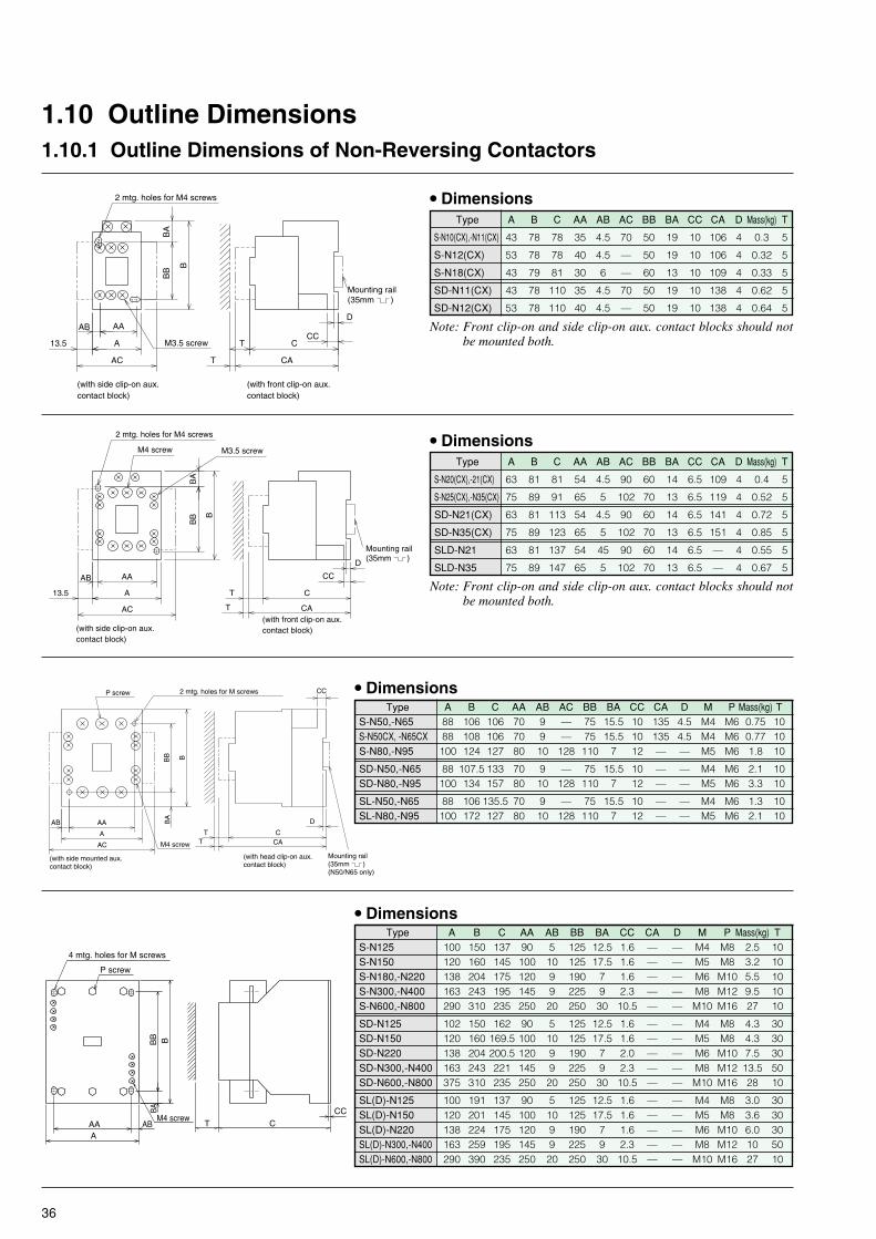
36
A B C AA AB AC BB BA CC CA D Mass(kg) T
S-N10(CX),-N11(CX) 43 78 78 35 4.5 70 50 19 10 106 4 0.3 5
S-N12(CX) 53 78 78 40 4.5 — 50 19 10 106 4 0.32 5
S-N18(CX) 43 79 81 30 6 — 60 13 10 109 4 0.33 5
SD-N11(CX) 43 78 110 35 4.5 70 50 19 10 138 4 0.62 5
SD-N12(CX) 53 78 110 40 4.5 — 50 19 10 138 4 0.64 5
1.10 Outline Dimensions1.10.1 Outline Dimensions of Non-Reversing Contactors
A B C AA AB AC BB BA CC CA D Mass(kg) T
S-N20(CX),-21(CX) 63 81 81 54 4.5 90 60 14 6.5 109 4 0.4 5
S-N25(CX),-N35(CX) 75 89 91 65 5 102 70 13 6.5 119 4 0.52 5
SD-N21(CX) 63 81 113 54 4.5 90 60 14 6.5 141 4 0.72 5
SD-N35(CX) 75 89 123 65 5 102 70 13 6.5 151 4 0.85 5
SLD-N21 63 81 137 54 45 90 60 14 6.5 — 4 0.55 5
SLD-N35 75 89 147 65 5 102 70 13 6.5 — 4 0.67 5
A B C AA AB AC BB BA CC CA D M P Mass(kg) TS-N50,-N65 88 106 106 70 9 — 75 15.5 10 135 4.5 M4 M6 0.75 10S-N50CX, -N65CX 88 108 106 70 9 — 75 15.5 10 135 4.5 M4 M6 0.77 10S-N80,-N95 100 124 127 80 10 128 110 7 12 — — M5 M6 1.8 10
SD-N50,-N65 88 107.5 133 70 9 — 75 15.5 10 — — M4 M6 2.1 10SD-N80,-N95 100 134 157 80 10 128 110 7 12 — — M5 M6 3.3 10
SL-N50,-N65 88 106 135.5 70 9 — 75 15.5 10 — — M4 M6 1.3 10SL-N80,-N95 100 172 127 80 10 128 110 7 12 — — M5 M6 2.1 10
• Dimensions
A B C AA AB BB BA CC CA D M P Mass(kg) TS-N125 100 150 137 90 5 125 12.5 1.6 — — M4 M8 2.5 10S-N150 120 160 145 100 10 125 17.5 1.6 — — M5 M8 3.2 10S-N180,-N220 138 204 175 120 9 190 7 1.6 — — M6 M10 5.5 10S-N300,-N400 163 243 195 145 9 225 9 2.3 — — M8 M12 9.5 10S-N600,-N800 290 310 235 250 20 250 30 10.5 — — M10 M16 27 10
SD-N125 102 150 162 90 5 125 12.5 1.6 — — M4 M8 4.3 30SD-N150 120 160 169.5 100 10 125 17.5 1.6 — — M5 M8 4.3 30SD-N220 138 204 200.5 120 9 190 7 2.0 — — M6 M10 7.5 30SD-N300,-N400 163 243 221 145 9 225 9 2.3 — — M8 M12 13.5 50SD-N600,-N800 375 310 235 250 20 250 30 10.5 — — M10 M16 28 10
SL(D)-N125 100 191 137 90 5 125 12.5 1.6 — — M4 M8 3.0 30SL(D)-N150 120 201 145 100 10 125 17.5 1.6 — — M5 M8 3.6 30SL(D)-N220 138 224 175 120 9 190 7 1.6 — — M6 M10 6.0 30SL(D)-N300,-N400 163 259 195 145 9 225 9 2.3 — — M8 M12 10 50SL(D)-N600,-N800 290 390 235 250 20 250 30 10.5 — — M10 M16 27 10
• Dimensions
P screw
4 mtg. holes for M screws
M4 screw
BA
T CCC
BB B
ABAAA
2 mtg. holes for M4 screws
M3.5 screw13.5
T CA
T
Mounting rail (35mm )
CC
D
AC
AB
A
AA
BA
BB
B
C
(with side clip-on aux.contact block)
(with front clip-on aux.contact block)
Note: Front clip-on and side clip-on aux. contact blocks should notbe mounted both.
Note: Front clip-on and side clip-on aux. contact blocks should notbe mounted both.
2 mtg. holes for M4 screws
M3.5 screwM4 screw
(with side clip-on aux.contact block)
(with front clip-on aux.contact block)
CA
D
CC
CT
BA
AC
13.5 A
AB AA
B
BB
T
Mounting rail (35mm )
P screw
M4 screw
2 mtg. holes for M screws
(with head clip-on aux.contact block)
CC
D
CT
BA
BB B
AB AA
AT CAAC
(with side mounted aux.contact block)
Mounting rail (35mm )(N50/N65 only)
• Dimensions
• Dimensions
Type
Type
Type
Type

37
1.10.2 Outline Dimensions of Reversing Contactors
TypeS-2xN10/N11S-2xN18S-2xN20/N21S-2xN25/N35S-2xN50/N65S-2xN80/N95S-2xN125S-2xN150S-2xN180/220S-2xN300/N400S-2xN600/N800
SD-2xN11SD-2xN21SD-2xN35SD-2xN50/N65SD-2xN80/N95SD-2xN125SD-2xN150SD-2xN220SD-2xN300/N400SD-2xN600/N800
Fig.aaabbbccccd
abbbbccccd
T5555
101030303050—
555
101030303050—
A9996136160216270276296370395660
99160160216270276296370395800
B787981
110115140150160215250—
78100113
116.5140150160215250—
C781098197112137148156189209—
110119129133167173
180.5214.5235—
AA353054150204247255275340365—
35150150204247255275340365—
AB4.53.54.5156
11.510.510.51515—
4.5556
11.510.510.51515—
AC212319————————
21—————————
BA506060100100100125125190225—
5090100100100125125190225—
BB19131488
3212.517.512.512.5—
19588
3212.517.512.512.5—
CC10106.51.62
101.61.61.62.3—
102
1.62
101.61.61.62.3—
N4443334444—
433334444—
MM4M4M4M4M5M6M6M6M8M8—
M4M4M4M5M6M6M6M8M8—
PM3.5M4M4M5M6M6M8M8
M10M12—
M3.5M4M5M6M6M8M8
M10M12—
QM3.5M3.5M3.5M3.5M4M4M4M4M4M4
M3.5M3.5M3.5M4M4M4M4M4M4
Mass(kg)0.640.750.81.32.64.35.77.212
20.554
1.31.72.04.56.49.210172964
• Dimensions
■ Latched Contactors(Reversing)
c)d) S(D)-2xN600/N800
b)
a)
a)
TypeSL(D)-2xN35SL(D)-2xN50/N65SL(D)-2xN80/N95SL(D)-2xN125SL(D)-2xN150SL(D)-2xN220SL(D)-2xN300/N400
Fig.aabbbbb
• DimensionsA
160216270276296370395
B113115184191201230263
C153
141.5137148156189209
AA150204247255275340365
AB56
11.510.510.51515
BA(BC)100100100125125190225
BB88
7453.558.52725
CC1.62
1011111414
N3334444
MM4M5M6M6M8M8M8
PM5M6M6M8M8
M10M12
QM3.5M4M4M4M4M4M4
Mass(kg)2.23.25.36.78.813
21.5
T5
101030303050
SL-2xN600/N800 (Mass: 60kg)
M4 screws
P screws
BB
BA B
ABAAA T C
CC
N-mtg holesfor M screws
b)
SL(D)-2xN21N mtg. holes for M screws
P screws
Q screws
CC
CT
B
BB
BA
A
AB AA
M16 screwsM4 screws
9023
0
370
620 10 2546 mtg holes for M10 screws
19
A
20
435
13.5
BB
B
N mtg. holes for M screws
P screwQ screw
CC
CT13.5 A
BA
AB AA
P screwQ screw N mtg. holes for M screws
CCCT
BB
BBA
AAABA
13.5AB
P screwQ screw
N mtg. holes for M screws
AA AC AAT
4
BB
BB
A
ACC
C
Mounting rail (35mm )
M3.5 screwM4 screw
4 mtg. holes for M4 screws
6.5419
136
8114
60
4.5
8 136.5
Mounting rail (35mm )
M16 screws M4 screwsM4 screws
2043
537
0
620 254
230
9030
10 19
175
6 mtg holes for M10 screws660
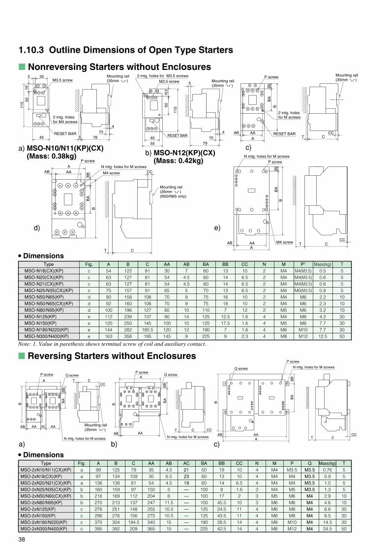
38
1.10.3 Outline Dimensions of Open Type Starters
■ Nonreversing Starters without Enclosures
a) MSO-N10/N11(KP)(CX)(Mass: 0.38kg)
c)
d) e)
b) MSO-N12(KP)(CX)(Mass: 0.42kg)
RESET BAR
2 mtg. holesfor M screws
P screw
AAT
B
AB CCCA
BBB
A
Mounting rail (35mm )M3.5 screw
2 mtg. holesfor M4 screws
10
1911
5
4
785
50
5 35
45RESET BAR
Mounting rail (35mm )
RESET BAR
M3.5 screw2 mtg. holes for M3.5 screws
5
104055
4
79
115
19.3
50
Mounting rail (35mm )
T5555
101030303050
TypeMSO-2xN10/N11(CX)(KP)MSO-2xN18(CX)(KP)MSO-2xN20/N21(CX)(KP)MSO-2xN25/N35(CX)(KP)MSO-2xN50/N60(CX)(KP)MSO-2xN80/N95(KP)MSO-2xN125(KP)MSO-2xN150(KP)MSO-2xN180/N220(KP)MSO-2xN300/N400(KP)
A9997
136160216270276296370395
B125134138159169213251276304392
C79
1098197
112137148156
194.5209
AA353054
150204247255275340365
AB4.56.54.556
11.510.510.51515
AC212319———————
BA506060
100100100125125190225
BB1913148
1745.524.543.528.542.5
CC10106.51.62
1011111414
N4443334444
MM4M4M4M4M5M6M6M6M8M8
PM3.5M4M4M5M6M6M8M8
M10M12
QM3.5M3.5M3.5M3.5M4M4M4M4M4M4
• DimensionsMass(kg)
0.760.91.01.32.94.66.68.514.524.5
Fig.aaabbbcccc
■ Reversing Starters without Enclosures
TypeMSO-N18(CX)(KP)MSO-N20(CX)(KP)MSO-N21(CX)(KP)MSO-N25/N35(CX)(KP)MSO-N50/N65(KP)MSO-N50/N65(CX)(KP)MSO-N80/N95(KP)MSO-N125(KP)MSO-N150(KP)MSO-N180/N220(KP)MSO-N300/N400(KP)
Note: 1. Value in parethesis shows terminal screw of coil and auxiliary contact.
• Dimensions
a) b) c)N mtg. holes for M screws
P screw Q screw
CC
AA AAAC
CTA
B
BB
BA
AB Mounting rail (35mm )
Q screwP screw
T C CCAB
BB
BA
AA
A
B
N mtg. holes for M screws
N mtg. holes for M screwsQ screw
P screw
ACC
T C
B
BB
BA
AB AA
N mtg. holes for M screws
M4 screw
P screw
CC
AAB AA
BBB
BA
T C
N mtg. holes for M screws
M4 screw
P screw
T
BB
BB
A
AAB AA
C
CC
Mounting rail (35mm )(N50/N65 only)
Fig.ccccdddeeee
A546363759092
100112120144163
B122127127157158160196239250282358
C81818191
106106127137145
180.5195
AA3054546570708090
100120145
AB7
4.54.5599
101410129
BA606060707575
110125125190225
BB1314141316187
12.517.5
79
CC106.56.56.51010121.61.61.62.3
N22222224444
MM4M4M4M4M4M4M5M4M5M6M8
P1
M4(M3.5)M4(M3.5)M4(M3.5)M5(M3.5)
M6M6M6M8M8
M10M12
Mass(kg)0.50.60.60.82.22.33.24.27.77.712.5
T5555
10101030303050

39
1.10.4 Outline Dimensions of Enclosed Motor Starters
■ Nonreversing Starters with Enclosures
• Dimensions
Type
MS-N10/K11(KP)
MS-N12(KP)
MS-N20(KP)/N21(KP)
MS-N25(KP)/N35(KP)
MS-N50(KP)
MS-N65(KP)
MS-N80/N95(KP)
MS-N125(KP)
MS-N150(KP)
MS-N180/N220(KP)
MS-N300/N400(KP)
A
76
76
104
135
160
160
190
230
270
270
440
• DimensionsAA
45
45
76
95
120
120
150
170
200
200
320
B
159
159
170
225
270
270
300
384
484
484
590
BA
120
120
140
165
220
220
260
330
400
400
480
BB
21
21
15
30
25
25
20
29
44
44
55
BC
6
6
6
6
12
12
12
12
12
12
12
C
97.5
97.5
110
126
145
145
163
190
209
209
220
CA
21.5
21.5
30
45
45
45
67
80
85
85
140/90*
M
4
5
6
6
6
6
7
9
9
9
11
N
22
22
22
28
22!35
22!35
22!35
44!50
44!50
44!50
62!78
Mass(kg)
0.8
0.9
1.1
2.0
3.2
3.2
4.0
8.0
12.8
16.2
28
AB
33
33
50
50
80
80
100
90
120
120
160
■ Enclosed Type Nonreversing Starters with Pushbuttons
* Left value is for power-supply side, right for load side.
MS-N10(KP)-N21(KP) MS-N25(KP)-N400(KP)
MS-N25PM(KP)-N95PM(KP)MS-N10PM(KP)-N21PM(KP)
BA
CA
CB
BC
AB
BB
2�2-fNknockout holes
4-fM mtg. holes
Earth terminal
AA
A
BBA
BB
BC
C
CA
AB2�2-fNknockout holes
4-fM mtg. holes
Earth terminal
AA
A
BC
A
CB
AB
AA
BA
BB
CA
2�2-f22knockout holes
3-fM mtg. holes
Earth terminal
3-fM mtg. holes
A
CB
BC
2�2-f22knockout holes Earth terminal
AA
AB
BA
CA
BB
104
Type
MS-N10/N11PM(KP)
MS-N20PM(KP)
MS-N21PM(KP)
MS-N25/N35PM(KP)
MS-N50/N65PM(KP)
MS-N80/N95PM(KP)
A
76
135
160
190
AA
45
95
120
150
76
BA
120
165
220
260
BB
21
30
25
20
BC
6
6
12
12
C
114
130
149
167
B
159
225
270
300
AB
33
50
80
100
CA
22
45
45
67
50 170 140 15 6 114
M
4
6
6
7
N
22
28
22!35
22!35
Mass(kg)
0.9
2.1
3.3
4.1
30 6 22 1.3
Related Documents